Embed Size (px)
Citation preview

*Research Support Instruments, Inc., 4325-B Forbes Boulevard, Lanham, MD 20706, USA. †[email protected]
Observation of monoenergetic protons from a near-critical gas target tailored by a hydrodynamic shock
Y.-H. Chen*†a, M. H. Hellea, A. Tinga, D. F. Gordona, M. N. Polyanskiyb, I. Pogorelskyb, M.
Babzienb, and Z. Najmudinc
aPlasma Physics Division, Naval Research Laboratory, Washington, DC 20375, USA
bAccelerator Test Facility, Brookhaven National Laboratory, Upton, New York 11973, USA cBlackett Laboratory, Imperial College London, London SW7 2AZ, UK
ABSTRACT We present our recent experimental results of monoenergetic protons accelerated from the interaction of an intense terawatt CO2 laser pulse with a near-critical hydrogen gas target, with its density profile tailored by a hydrodynamic shock. A 5-ns Nd:YAG laser pulse is focused onto a piece of stainless steel foil mounted at the front edge of the gas jet nozzle orifice. The ablation launches a spherical shock into the near-critical gas column, which creates a sharp density gradient at the front edge of the target, with ~ 6X local density enhancement up to several times of critical density within ~<100 microns. With such density profile, we have obtained monoenergetic proton beams with good shot-to-shot reproducibility and energies up to 1.2 MeV.
Keywords: laser acceleration of protons, ion acceleration, shock wave acceleration, laser hole boring, CO2 lasers, near-critical plasmas
1. INTRODUCTION Energetic ions can be produced via high intensity laser-plasma interactions, and several acceleration mechanisms, such as target normal sheath acceleration (TNSA),1 radiation pressure acceleration (RPA),2 break out afterburner (BOA),3 and magnetic vortex acceleration,4 have been identified. Compared with RF-based accelerators, the laser-based ion sources have many superior properties, such as high acceleration gradient, high brightness, and short bunch length. However for practical accelerator applications, a high-energy, monoenergetic beam with high repetition rate is generally required.
Using picosecond, terawatt CO2 lasers at Brookhaven National Laboratory and at UCLA with hydrogen gas targets, monoenergetic proton acceleration had been experimentally observed by Palmer et al.5,6 and by Haberberger el al.,7 respectively. Palmer et al. reported protons accelerated by laser “hole-boring” into the plasma with energy up to ~ 1 MeV.5 On the other hand, Haberberger et al. observed monoenergetic protons up to 21 MeV, and they suggested that the acceleration is contributed by a collisionless, electrostatic shock launched into the plasma.7 The combination of CO2 lasers with gas jet targets is advantageous because the plasma density produced by a supersonic gas jet nozzle is usually in the range of 1018 – 1020 cm−3, which is close to the critical density nc = 1019 cm−3 at CO2 laser wavelength ~10 µm, at which the hole-boring and shock wave acceleration are most efficient. Meanwhile the gas jet plasma is transparent at the wavelength of solid-state lasers, which enables optical probing of the plasma density profile. Moreover, the gas jet target does not produce solid contaminant and is immediately renewable after each laser shot, which is suitable for high rep rate applications.
It has been found that the shock wave and hole boring acceleration require a sharp target boundary, which is generally difficult to achieve with gas jet nozzles. This suggests that density tailoring on the gas target is necessary. In Ref. 7, Haberberger et al. reported that the ion acceleration relies on the intrinsic pulse train structure of UCLA’s CO2 laser system. Optimal acceleration occurs when the front edge of the plasma is steepened by the radiation pressure from the earlier, weaker pulses in the pulse train. Recently, Tresca et al. found that monoenergetic ions are produced when there is a low-energy prepulse 25 ns before the main pulse from BNL’s CO2 laser system.8 The prepulse ionizes and heats the gas near the focus, and then the expanding blast wave forms a hollow “bubble” surrounded by a sharp, high-density wall
Laser Acceleration of Electrons, Protons, and Ions III; and Medical Applications of Laser-Generated Beams of Particles III, edited by Kenneth W. D. Ledingham, Eric Esarey, Klaus Spohr, Carl B. Schroeder, Paul McKenna, Florian J. Grüner,
Paul R. Bolton, Proc. of SPIE Vol. 9514, 95140C · © 2015 SPIE · CCC code: 0277-786X/15/$18 · doi: 10.1117/12.2182094
Proc. of SPIE Vol. 9514 95140C-1
Downloaded From: http://proceedings.spiedigitallibrary.org/ on 05/26/2015 Terms of Use: http://spiedl.org/terms

before the main pulse arrives. Monoenergetic ions are observed at an optimal prepulse energy.8 However, for both UCLA and BNL laser systems, there is no independent control on the prepulse structure, timing, or energy, for shaping the target density profile consistently.
2. EXPERIMENT In this paper, we use a new method to tailor the gas target density profile for ion acceleration at the near-critical density. The experiment is carried out with the picosecond terawatt CO2 laser at Brookhaven National Laboratory,9 and the setup is shown in Fig. 1. A piece of stainless steel foil is mounted near the 1-mm-diameter orifice of the gas jet nozzle, and a 5-ns, 70-mJ, 1064 nm Nd:YAG laser pulse is focused on it after firing the gas jet. The laser-ablated material is ejected from the foil surface at supersonic velocity, launching a hydrodynamic shock into the hydrogen gas jet before the CO2 laser pulse arrives. This creates a sharp density spike across the shock front, followed by a depression region at the front edge of the target. This method has been previously used for generating near-critical targets for magnetic vortex acceleration of protons with a femtosecond Ti:Sapphire laser pulse at Naval Research Laboratory.10 The CO2 pulse is then focused at the shock front ~ 1 mm above the nozzle with a spot radius w0 = 60 µm and maximum a0 ~ 1. A low-energy, 10 ps, 532 nm Nd:YAG laser pulse is used to transversely probe the interaction region with an interferometer. The accelerated protons are detected by a Thomson parabola energy spectrometer ~ 15 cm after the interaction region.
H2 gas jet
shock 5ns, 70 mJ Nd:YAG laser
CO2 laser
steel foil
to ion detector
nozzle Figure 1. Experimental setup.
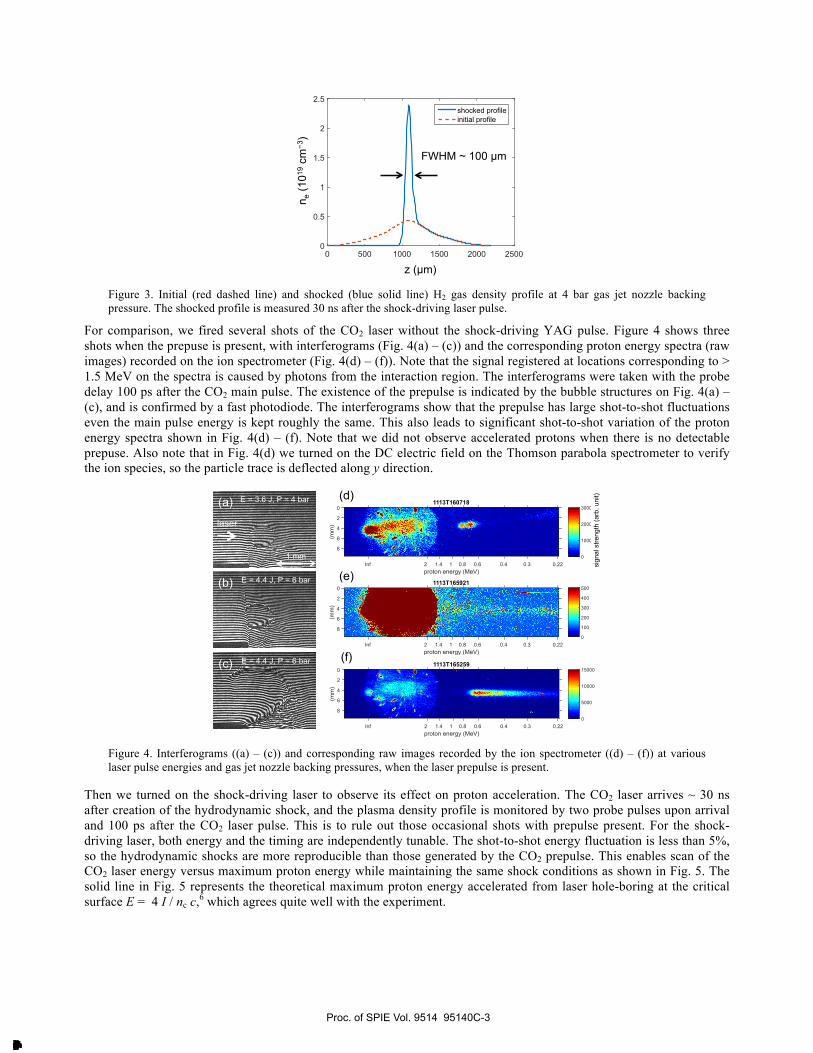
We first characterize the temporal evolution of the hydrodynamic shock launched into the hydrogen gas, which is shown as a series of interferograms at various probe delays in Fig. 2(a). The shock-driving Nd:YAG laser is focused onto the thin steel foil from the top right corner of the images, and the backing pressure of the gas jet nozzle is 12 bar. At earlier delays the fringe shift caused by laser ablation near the edge of the foil is clearly visible. Figure 2(b) shows the horizontal velocity of the shock front estimated from Fig. 2(a). Note that as the shock velocity decreases rapidly, the shock front still moves at a high Mach number at t = 40 ns, indicating that the shock compression is still strong enough. For optimal acceleration, we set the CO2 pulse delay 30 – 40 ns after the shock driving pulse and decrease the nozzle backing pressure to 4 bar. The initial and the shocked density profiles 2nH2 (corresponding to ne after ionization) obtained from the interferometry are shown in Fig 3. The peak density at the shocked region is 2.4 nc over a FWHM length of ~ 100 µm, which agrees with the local density increase factor in the strong shock regime (γ + 1) / (γ−1) = 6, where γ is the specific heat ratio of hydrogen.
Figure 2. (a) Temporal evolution of the hydrodynamic shock measured using interferometry. (b) Shock front horizontal velocity obtained from (a).
Proc. of SPIE Vol. 9514 95140C-2
Downloaded From: http://proceedings.spiedigitallibrary.org/ on 05/26/2015 Terms of Use: http://spiedl.org/terms
0 500 1000 1500 2000 25000
0.5
1
1.5
2
2.5
shocked profile
initial profile
z (µm)
n e (1
019 c
m−3
)
FWHM ~ 100 µm
Figure 3. Initial (red dashed line) and shocked (blue solid line) H2 gas density profile at 4 bar gas jet nozzle backing pressure. The shocked profile is measured 30 ns after the shock-driving laser pulse.
For comparison, we fired several shots of the CO2 laser without the shock-driving YAG pulse. Figure 4 shows three shots when the prepuse is present, with interferograms (Fig. 4(a) – (c)) and the corresponding proton energy spectra (raw images) recorded on the ion spectrometer (Fig. 4(d) – (f)). Note that the signal registered at locations corresponding to > 1.5 MeV on the spectra is caused by photons from the interaction region. The interferograms were taken with the probe delay 100 ps after the CO2 main pulse. The existence of the prepulse is indicated by the bubble structures on Fig. 4(a) – (c), and is confirmed by a fast photodiode. The interferograms show that the prepulse has large shot-to-shot fluctuations even the main pulse energy is kept roughly the same. This also leads to significant shot-to-shot variation of the proton energy spectra shown in Fig. 4(d) – (f). Note that we did not observe accelerated protons when there is no detectable prepuse. Also note that in Fig. 4(d) we turned on the DC electric field on the Thomson parabola spectrometer to verify the ion species, so the particle trace is deflected along y direction.
1113T165921
proton energy (MeV)Inf 2 1.4 1 0.8 0.6 0.4 0.3 0.22
(mm
)
0
2
4
6
8
0
100
200
300
400
500
1113T160718
proton energy (MeV)Inf 2 1.4 1 0.8 0.6 0.4 0.3 0.22
(mm
)
0
2
4
6
8
0
1000
2000
3000
1113T165259
proton energy (MeV)Inf 2 1.4 1 0.8 0.6 0.4 0.3 0.22
(mm
)
0
2
4
6
8
0
5000
10000
15000
(d)
(e)
(f)
sign
al s
treng
th (a
rb. u
nit) E = 3.6 J, P = 4 bar
E = 4.4 J, P = 6 bar
E = 4.4 J, P = 6 bar
laser
(a)
(b)
(c)
1 mm
Figure 4. Interferograms ((a) – (c)) and corresponding raw images recorded by the ion spectrometer ((d) – (f)) at various laser pulse energies and gas jet nozzle backing pressures, when the laser prepulse is present.
Then we turned on the shock-driving laser to observe its effect on proton acceleration. The CO2 laser arrives ~ 30 ns after creation of the hydrodynamic shock, and the plasma density profile is monitored by two probe pulses upon arrival and 100 ps after the CO2 laser pulse. This is to rule out those occasional shots with prepulse present. For the shock-driving laser, both energy and the timing are independently tunable. The shot-to-shot energy fluctuation is less than 5%, so the hydrodynamic shocks are more reproducible than those generated by the CO2 prepulse. This enables scan of the CO2 laser energy versus maximum proton energy while maintaining the same shock conditions as shown in Fig. 5. The solid line in Fig. 5 represents the theoretical maximum proton energy accelerated from laser hole-boring at the critical surface E = 4 I / nc c,6 which agrees quite well with the experiment.
Proc. of SPIE Vol. 9514 95140C-3
Downloaded From: http://proceedings.spiedigitallibrary.org/ on 05/26/2015 Terms of Use: http://spiedl.org/terms

0
0.5
1
1.5
0 1 2 3 4 5
max
imum
pro
ton
ener
gy (M
eV)
CO2 laser energy (J)
E = 4I/ncc
Figure 5. CO2 laser energy vs. measured maximum proton energy. The gas jet nozzle backing pressure is 4 bar. The solid line indicate the theoretical maximum proton energy accelerated by laser hole boring E = 4I / nc with n = nc.
3. SIMULATION Figure 6(a) shows a proton spectrum and its raw image recorded by the spectrometer, with 4.5 J CO2 laser energy and shock-driving YAG laser pulse. Quasi-monoenergetic features are observed at around 1.1 MeV and 0.7 MeV. Similar mono-energetic features can be observed for most of the shots with laser energy > 3 J. To better understand the acceleration mechanism, we carried out a 1-D PIC simulation using the code turboWAVE11 with the shocked plasma density profile and laser intensity a0 = 1, and the proton energy spectrum is shown in Fig. 6(b). The simulation also shows two peaks at ~1.2 MeV and ~ 0.7 MeV, which agrees well with the experiment. To determine the origin of these spectral peaks, we examine the temporal evolution of the longitudinal electric field Ez from the simulation as shown in Fig. 7(a). At t = 0, the rising edge of the laser pulse enters the simulation box at z = 75 µm. At t ~ 6 ps, 2 – 3 electrostatic shocks appear after the critical surface and propagate across the plasma at a near-constant velocity. The velocity of the first (fastest) shock front is vs = 5.9 × 10⁶ m/s, and the reflected protons can obtain a maximum energy (1/2) mp (2vs)2 = 0.7 MeV, which is the origin of the lower-energy spectral peak observed in Fig. 6(a). Finally, the proton momentum phase space diagrams at t = 5.5 ps (the laser pulse is interacting with the plasma) and t = 10.5 ps (the laser pulse is gone) are shown in Figs. 7(b) and 7(c), respectively. A portion of the protons in the laser-plasma interaction region are accelerated to ~ 1 MeV within the first 5.5 ps, as shown in Fig. 7(b). Beyond 5.5 ps, no more protons are accelerated to this energy. Therefore the observed 1.1 MeV proton spectral peak is contributed by the radiation pressure of the laser pulse imposed on the plasma. On the other hand, 3 electrostatic shocks start to form after ~ 6 ps, and can be seen in Fig. 7(c). The first shock front accelerates protons to ~ 0.7 – 0.8 MeV, which is consistent with the temporal evolution of Ez shown in Fig. 7(a). Some protons are accelerated at the second and the third shock front but they are subsequently reflected back by the previous one. These protons are thus trapped between the shock fronts, and the kinetic energy gradually dissipates away along with the shocks while moving in the plasma. Note that we recently preformed a 2-D simulation, and preliminary analysis shows that the results can also reproduce the spectral peaks from the experiment. Detailed analysis is ongoing and the results will be published in another journal paper.
energy (MeV)0.2 0.4 0.6 0.8 1 1.2 1.4
dN/d
E (a
rb. u
nit)
0
100
200
300
400
500
600
700
800E = 4.5J
T145247
proton energy (MeV)Inf 2 1.4 1 0.8 0.6 0.4 0.3 0.22
(mm
)
0
2
4
6
8
0
2000
4000
6000
8000
(a) (b) experiment simulation
Figure 6. (a) Measured proton spectrum and its raw image recorded by the spectrometer, with 4.5 J CO2 laser energy and shock-driving pulse; (b) proton spectrum obtained from 1-D PIC simulation using turboWAVE.
Proc. of SPIE Vol. 9514 95140C-4
Downloaded From: http://proceedings.spiedigitallibrary.org/ on 05/26/2015 Terms of Use: http://spiedl.org/terms

-50
0
50
100
150
1 MeV
0.7 MeV
p z/m
ec
z (µm) 160 280 200 240
t = 5.5 ps t = 10.5 ps
160 280 200 240 100 120 140 160-50
0
50
100
150
-5
-4.5
-4
-3.5
-3
-2.5
-2
-1.5
-1
-0.5
0
0
1
2
3
4
5
log
(ni)
(arb
. uni
t)
(a)
(b) (c)
t (ps
)
20
12
16
4
8
z (µm)
laser critical surface
200 100 150 250
Eze / mecω0 -1 1 0
75
Figure 7. (a) The temporal evolution of Ez, and the phase space of protons at (b) t = 5.5 ps and (c) t = 10.5 ps. The electrostatic shock fronts (3 – 4) between z = 220 – 240 µm and the protons reflected by them are visible in (c).
4. CONCLUSION In conclusion, we observed monoenergetic protons from the terawatt CO2 laser interactions with a H2 gas target, with its density profile steepened by a hydrodynamic shock. A Nd:YAG laser with moderate energy is used to generate the hydrodynamic shock via ablation of metal. Simulations suggest that both SWA and hole boring are the main acceleration mechanisms, while the highest energy spectral peak at ~ 1 MeV is contributed by laser hole boring.
ACKNOWLEDGEMENT This work is supported by U.S. Department of Energy.
REFERENCES
[1] R. A. Snavely, M. H. Key, S. P. Hatchett, T. E. Cowan, M. Roth, T. W. Phillips, M. A. Stoyer, E. A. Henry, T. C. Sangster, M. S. Singh, et al., “Intense High-Energy Proton Beams from Petawatt-Laser Irradiation of Solids,” Phys. Rev. Lett. 85, 2945 (2000).
Proc. of SPIE Vol. 9514 95140C-5
Downloaded From: http://proceedings.spiedigitallibrary.org/ on 05/26/2015 Terms of Use: http://spiedl.org/terms

[2] A. Macchi, F. Cattani, T. V. Liseykina, and F. Cornolti, “Laser Acceleration of Ion Bunches at the Front Surface of Overdense Plasmas,” Phys. Rev. Lett. 94, 165003 (2005).
[3] L. Yin, B. J. Albright, B. M. Hegelich, and J. C. Fernandez, “GeV laser ion acceleration from ultrathin targets: The laser break-out afterburner,” Laser Part. Beams 24, 291 (2006).
[4] S. V. Bulanov, D. V. Dylov, T. Z. Esirkepov, F. F. Kamenets, and D. V. Sokolov, “Ion acceleration in a dipole vortex in a laser plasma corona,” Plasma Phys. Rep. 31, 369 (2005).
[5] C. A. J. Palmer, N. P. Dover, I. Pogorelsky, M. Babzien, G. I. Dudnikova, M. Ispiriyan, M. N. Polyanskiy, J. Schreiber, P. Shkolnikov, V. Yakimenko, and Z. Najmudin, “Monoenergetic Proton Beams Accelerated by a Radiation Pressure Driven Shock,” Phys. Rev. Lett. 106, 014801 (2011).
[6] Z. Najmudin, C. A. J. Palmer, N. P. Dover, I. Pogorelsky, M. Babzien, A. E. Dangor, G. I. Dudnikova, P. S. Foster, J. S. Green, M. Ispiriyan, D. Neely, M. N. Polyanskiy, J. Schreiber, P. Shkolnikov, and V. Yakimenko, “Observation of impurity free monoenergetic proton beams from the interaction of a CO2 laser with a gaseous target,” Phys. Plasmas 18, 056705 (2011).
[7] D. Haberberger, S. Tochitsky, F. Fiuza, C. Gong, R. A. Fonseca, L. O. Silva, W. B. Mori, and C. Joshi, “Collisionless shocks in laser-produced plasma generate monoenergetic high-energy proton beams,” Nature Phys. 8, 95 (2012).
[8] O. Tresca, N. P. Dover, N. Cook, C. Maharjan, M. N. Polyanskiy, Z. Najmudin, P. Shkolnikov, and I. Pogorelsky, “Spectral modification of shock accelerated ions using hydrodynamically shaped gas target,” arXiv:1503.06180 (manuscript submitted to Phys. Rev. Lett).
[9] I. V. Pogorelsky, V. Yakimenko, M. Polyanskiy, P. Shkolnikov, M. Ispiryan, D. Neely, P. McKenna, D. Carroll, Z. Najmudin, and L. Willingale, “Ultrafast CO2 laser technology: Application in ion acceleration,” Nucl. Instrum Methods Phys. Res. A 620, 67 (2010).
[10] M. H. Helle, D. F. Gordon, D. Kaganovich, and A. Ting, "Laser Accelerated Ions from Near Critical Gaseous Targets," manuscript submitted to Advanced Accelerator Concepts Workshop 2014.
[11] D. F. Gordon, W. B. Mori, and T. M. Antonsen, Jr., “A Ponderomotive Guiding Center Particle-in-Cell Code for Efficient Modeling of Laser–Plasma Interactions,” IEEE Trans. Plasma Sci. 28, 1135 (2000).
Proc. of SPIE Vol. 9514 95140C-6
Downloaded From: http://proceedings.spiedigitallibrary.org/ on 05/26/2015 Terms of Use: http://spiedl.org/terms
All in-text references underlined in blue are linked to publications on ResearchGate, letting you access and read them immediately.