Embed Size (px)
Citation preview
Modular multistage pumps
SIHImulti
Type MSL, MSM
133.23301.57.01 E PUMP TECHNOLOGY SIHImulti MSL, MSM
02/2008
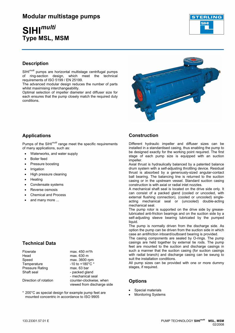
Description SIHImulti pumps are horizontal multistage centrifugal pumps of ring-section design, which meet the technical requirements of ISO 5199 / EN 25199. The advanced modular design reduces the number of parts whilst maximising interchangeability. Optimal selection of impeller diameter and diffuser size for each ensures that the pump closely match the required duty conditions.
Applications Pumps of the SIHImulti range meet the specific requirements of many applications, such as:
• Waterworks, and water supply • Boiler feed • Pressure boosting • Irrigation • High pressure cleaning • Heating • Condensate systems • Reverse osmosis • Chemical and Process • and many more ...
Technical Data Flowrate max. 450 m³/h Head max. 630 m Speed max. 3600 rpm Temperature -10 to +180°C * Pressure Rating max. 63 bar Shaft seal - packed gland - mechanical seal Direction of rotation counter-clockwise, when viewed from discharge side * 200°C as special design for example pump feet are mounted concentric in accordance to ISO 9905
Construction Different hydraulic impeller and diffuser sizes can be installed in a standardised casing, thus enabling the pump to be designed exactly for the working point required. The first stage of each pump size is equipped with an suction impeller. Axial thrust is hydraulically balanced by a patented balance drum system with a self-adjusting throttling device. Residual thrust is absorbed by a generously-sized angular-contact ball bearing. The balancing line is returned to the suction casing or in the upstream vessel. Standard suction casing construction is with axial or radial inlet nozzles. A mechanical shaft seal is located on the drive side only. It can consist of a packed gland (cooled or uncooled, with external flushing connection), (cooled or uncooled) single-acting mechanical seal or (uncooled) double-acting mechanical seal. The pump rotor is supported on the drive side by grease-lubricated anti-friction bearings and on the suction side by a self-adjusting sleeve bearing lubricated by the pumped liquid. The pump is normally driven from the discharge side. As option the pump can be driven from the suction side in which case an antifriction inboard/outboard bearing is provided. The casing components are sealed by O-rings. The pump casings are held together by external tie rods. The pump feet are mounted to the suction and discharge casings in such a manner that the suction casing (for suction casings with radial branch) and discharge casing can be swung to suit the installation conditions. All pump sizes can be provided with one or more dummy stages, if required. Options • Special materials • Monitoring Systems
SIHImulti
2
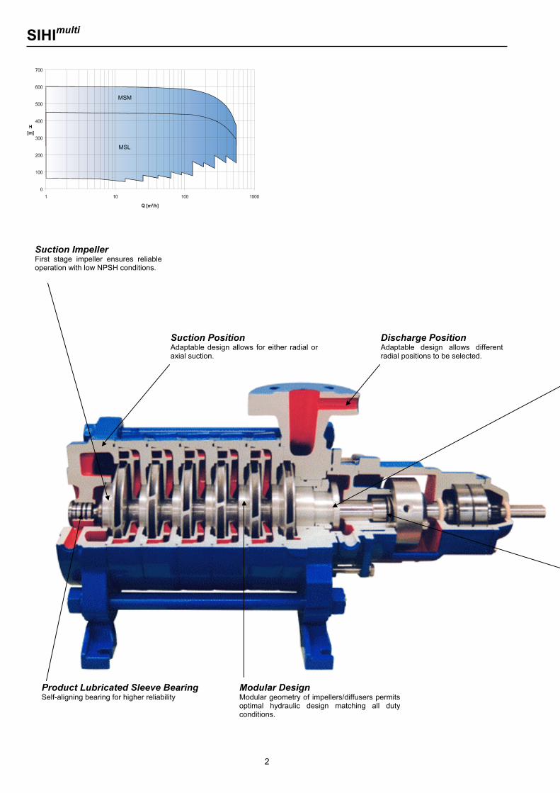
MSM
MSL
Suction Impeller First stage impeller ensures reliableoperation with low NPSH conditions.
Modular Design Modular geometry of impellers/diffusers permits optimal hydraulic design matching all duty conditions.
Discharge Position Adaptable design allows different radial positions to be selected.
Suction Position Adaptable design allows for either radial oraxial suction.
Product Lubricated Sleeve Bearing Self-aligning bearing for higher reliability
SIHImulti
3
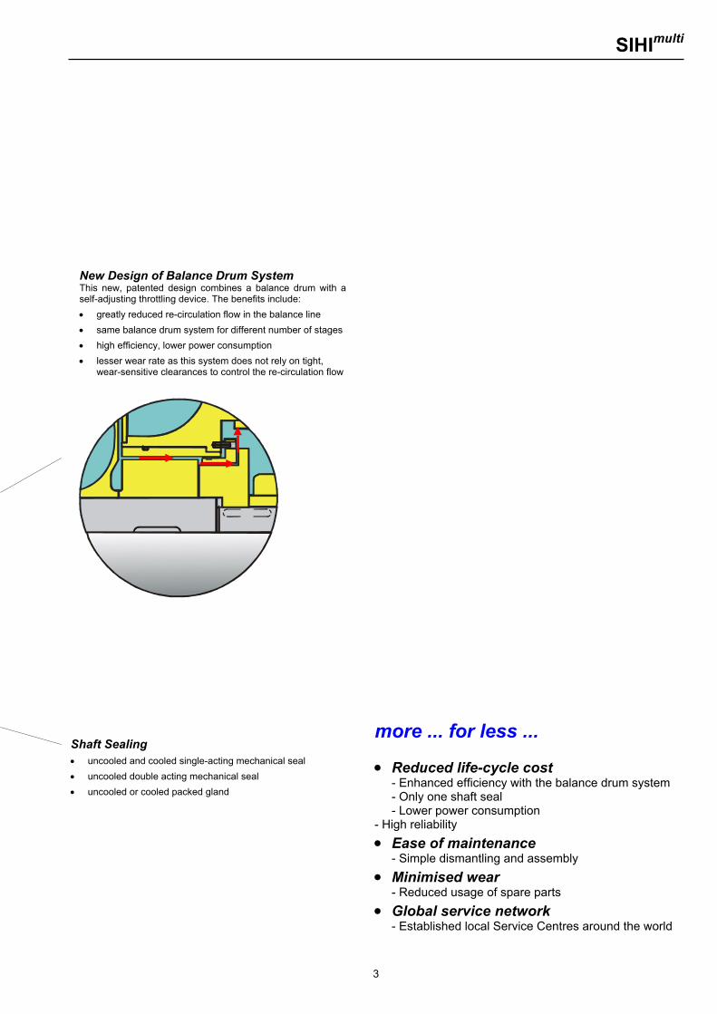
New Design of Balance Drum System This new, patented design combines a balance drum with aself-adjusting throttling device. The benefits include: • greatly reduced re-circulation flow in the balance line • same balance drum system for different number of stages• high efficiency, lower power consumption • lesser wear rate as this system does not rely on tight,
wear-sensitive clearances to control the re-circulation flow
Shaft Sealing • uncooled and cooled single-acting mechanical seal • uncooled double acting mechanical seal • uncooled or cooled packed gland
more ... for less ... • Reduced life-cycle cost
- Enhanced efficiency with the balance drum system - Only one shaft seal - Lower power consumption
- High reliability • Ease of maintenance
- Simple dismantling and assembly • Minimised wear
- Reduced usage of spare parts • Global service network
- Established local Service Centres around the world
SIHImulti
4
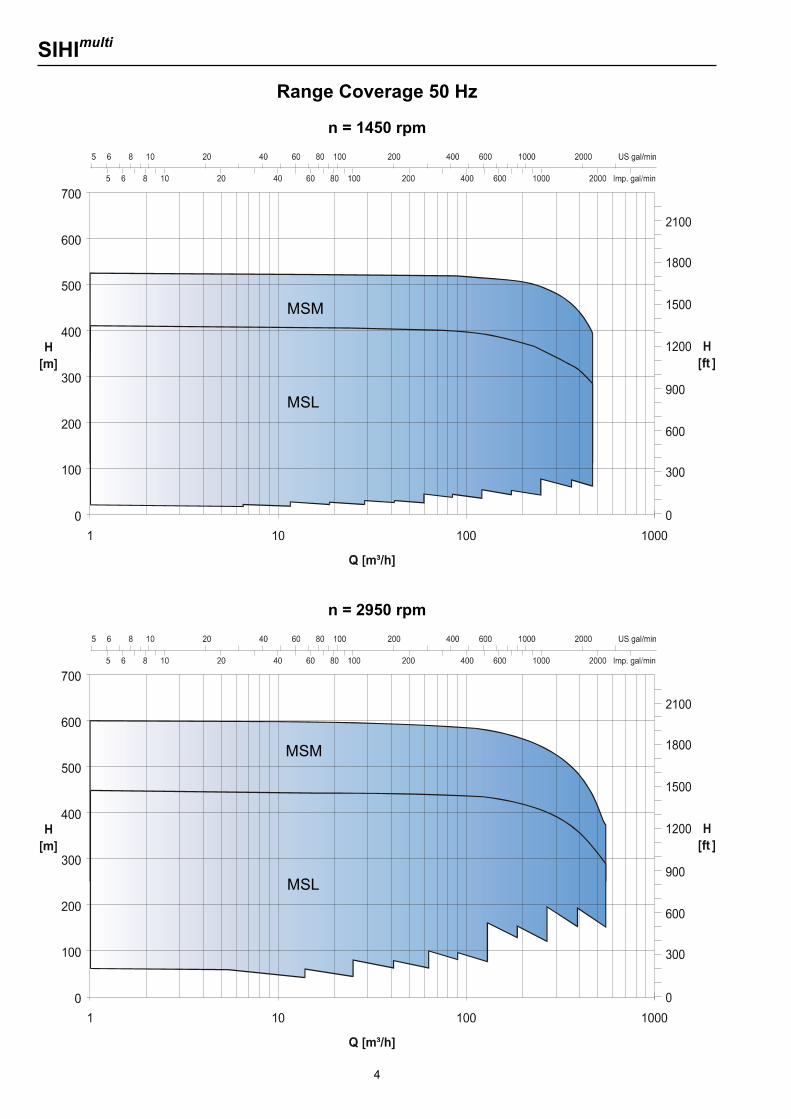
Range Coverage 50 Hz
n = 1450 rpm
MSM
MSL
n = 2950 rpm
MSM
MSL
SIHImulti
5
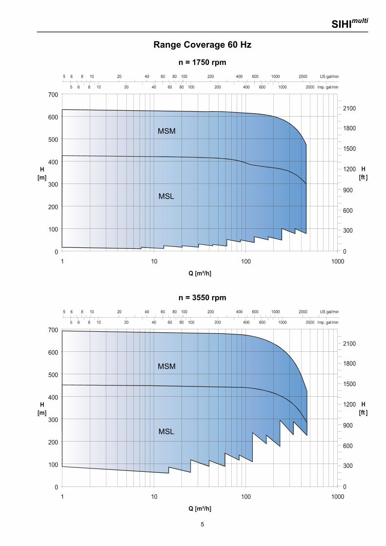
Range Coverage 60 Hz
n = 1750 rpm
MSM
MSL
n = 3550 rpm
MSM
MSL
SIHImulti
6
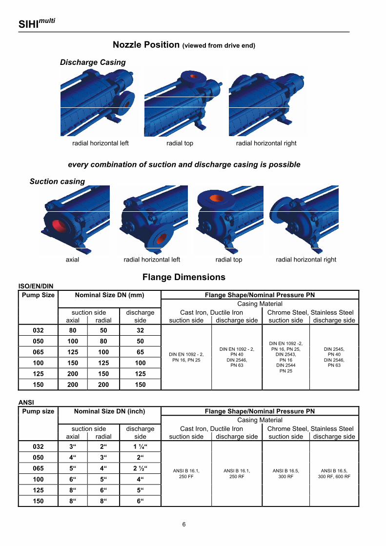
Nozzle Position (viewed from drive end)
Discharge Casing
every combination of suction and discharge casing is possible Suction casing
Flange Dimensions ISO/EN/DIN Pump Size Nominal Size DN (mm) Flange Shape/Nominal Pressure PN
Casing Material suction side discharge Cast Iron, Ductile Iron Chrome Steel, Stainless Steel axial radial side suction side discharge side suction side discharge side
032 80 50 32
050 100 80 50 DIN EN 1092 -2,
065 125 100 65 DIN EN 1092 - 2,
DIN EN 1092 - 2, PN 40
PN 16, PN 25, DIN 2543,
DIN 2545, PN 40
100 150 125 100 PN 16, PN 25 DIN 2546, PN 63
PN 16 DIN 2544
DIN 2546, PN 63
125 200 150 125 PN 25
150 200 200 150
ANSI
Pump size Nominal Size DN (inch) Flange Shape/Nominal Pressure PN Casing Material suction side discharge Cast Iron, Ductile Iron Chrome Steel, Stainless Steel axial radial side suction side discharge side suction side discharge side
032 3“ 2“ 1 ¼“
050 4“ 3“ 2“
065 5“ 4“ 2 ½“ ANSI B 16.1,
ANSI B 16.1,
ANSI B 16.5,
ANSI B 16.5,
100 6“ 5“ 4“ 250 FF 250 RF 300 RF 300 RF, 600 RF
125 8“ 6“ 5“
150 8“ 8“ 6“
radial horizontal left radial top radial horizontal right
radial horizontal left radial top radial horizontal right axial
SIHImulti
7
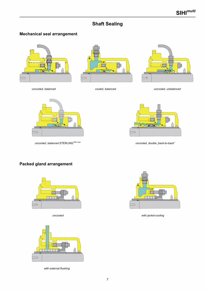
Shaft Sealing Mechanical seal arrangement
uncooled, balanced cooled, balanced uncooled, unbalanced
uncooled, balanced STERLINGGNZ seal uncooled, double „back-to-back“ Packed gland arrangement
uncooled with jacket-cooling
with external flushing
SIHImulti
8
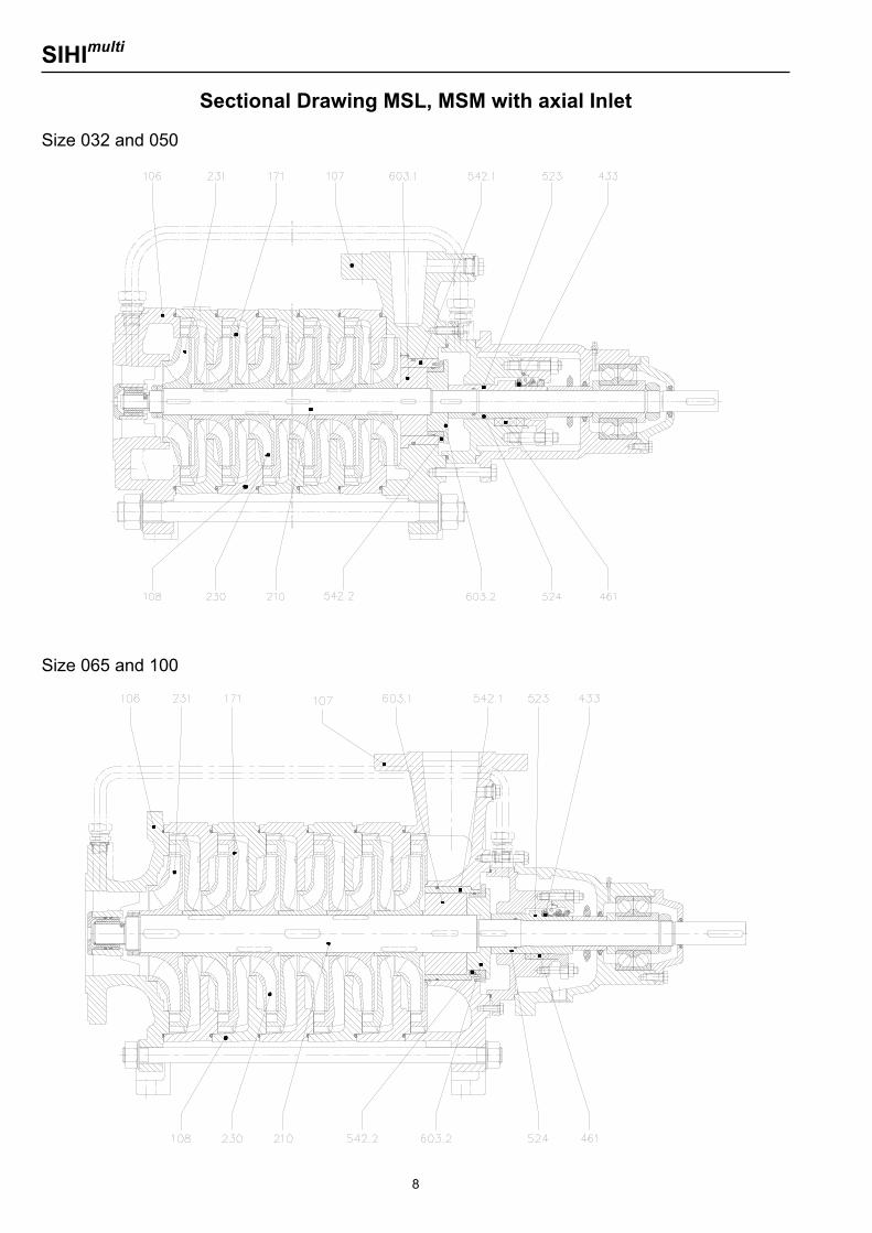
Sectional Drawing MSL, MSM with axial Inlet Size 032 and 050
Size 065 and 100
SIHImulti
9
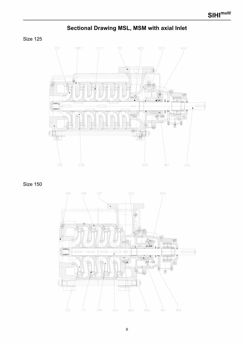
Sectional Drawing MSL, MSM with axial Inlet Size 125
Size 150
SIHImulti
10
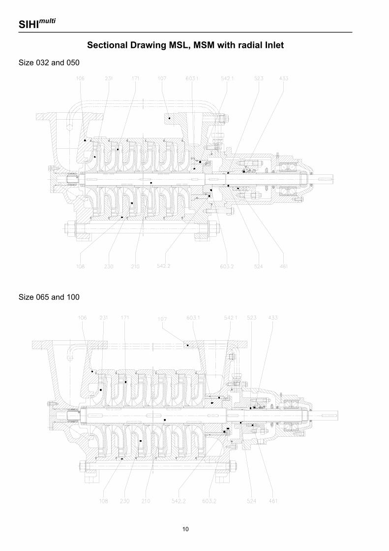
Sectional Drawing MSL, MSM with radial Inlet Size 032 and 050
Size 065 and 100
SIHImulti
11
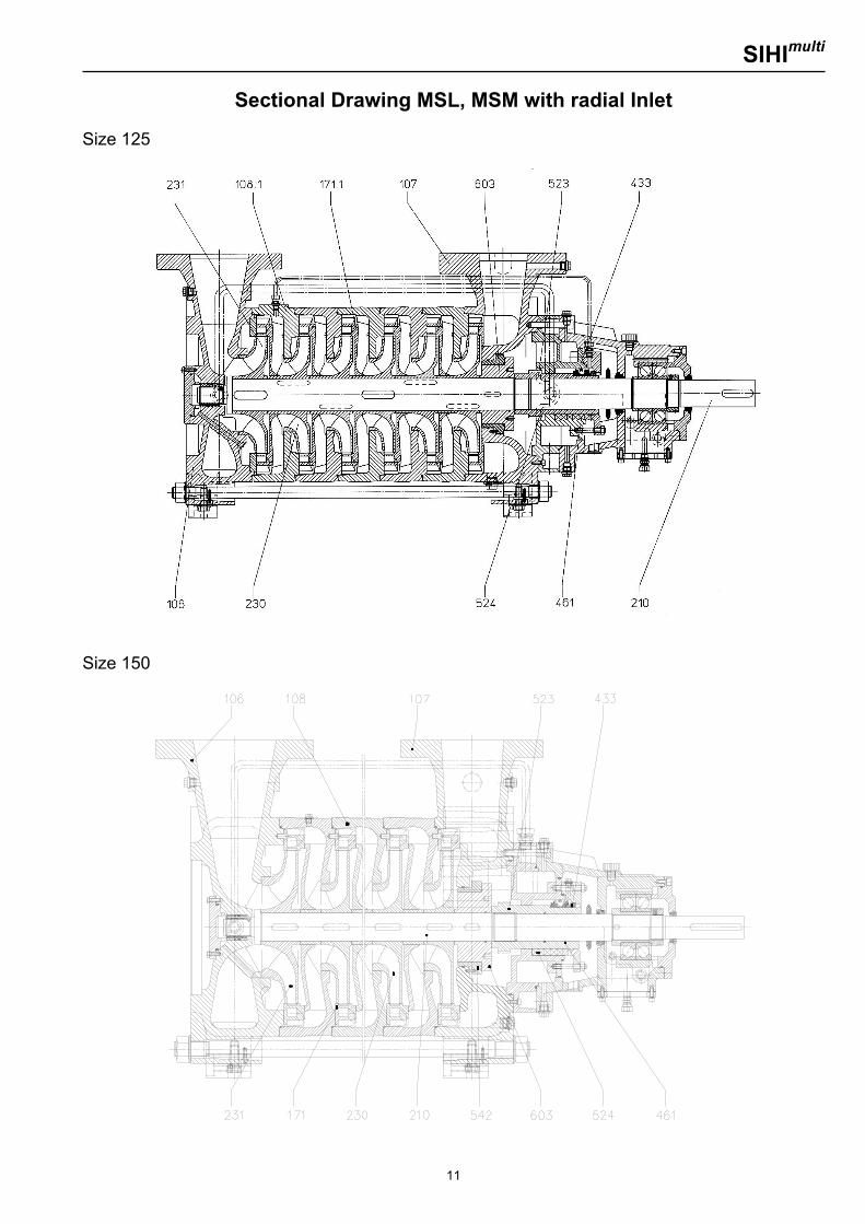
Sectional Drawing MSL, MSM with radial Inlet Size 125
Size 150
SIHImulti
12
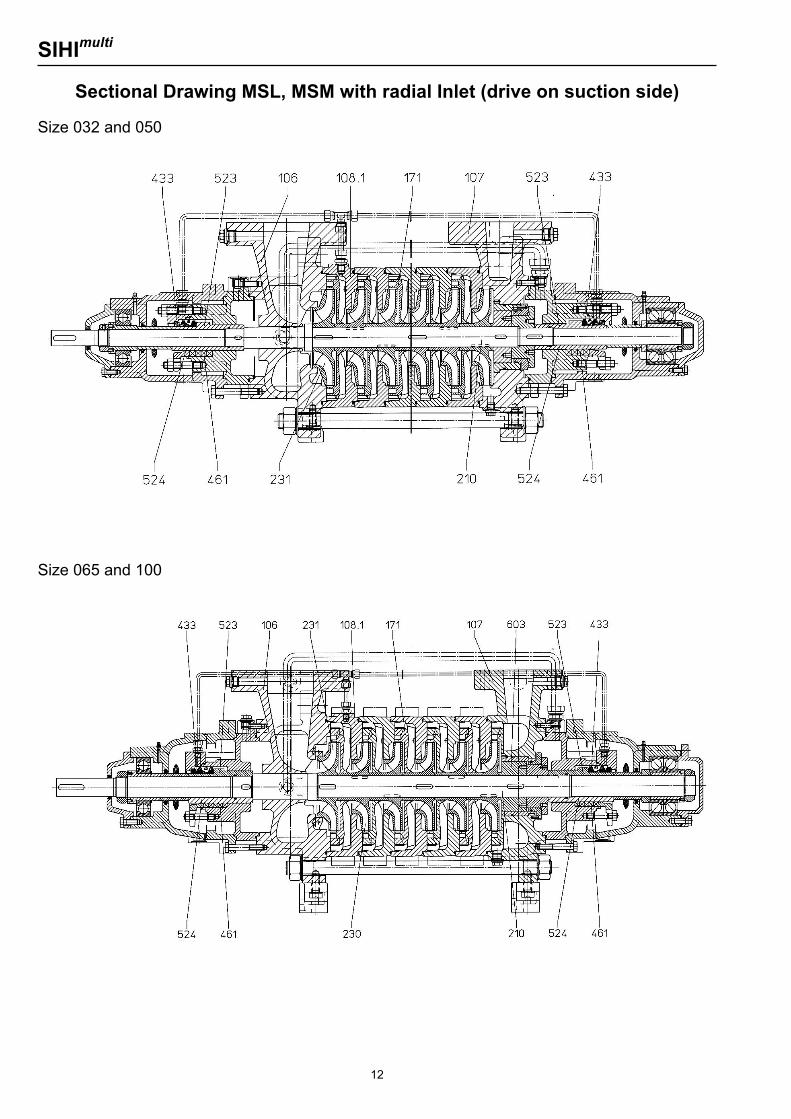
Sectional Drawing MSL, MSM with radial Inlet (drive on suction side) Size 032 and 050
Size 065 and 100
SIHImulti
13
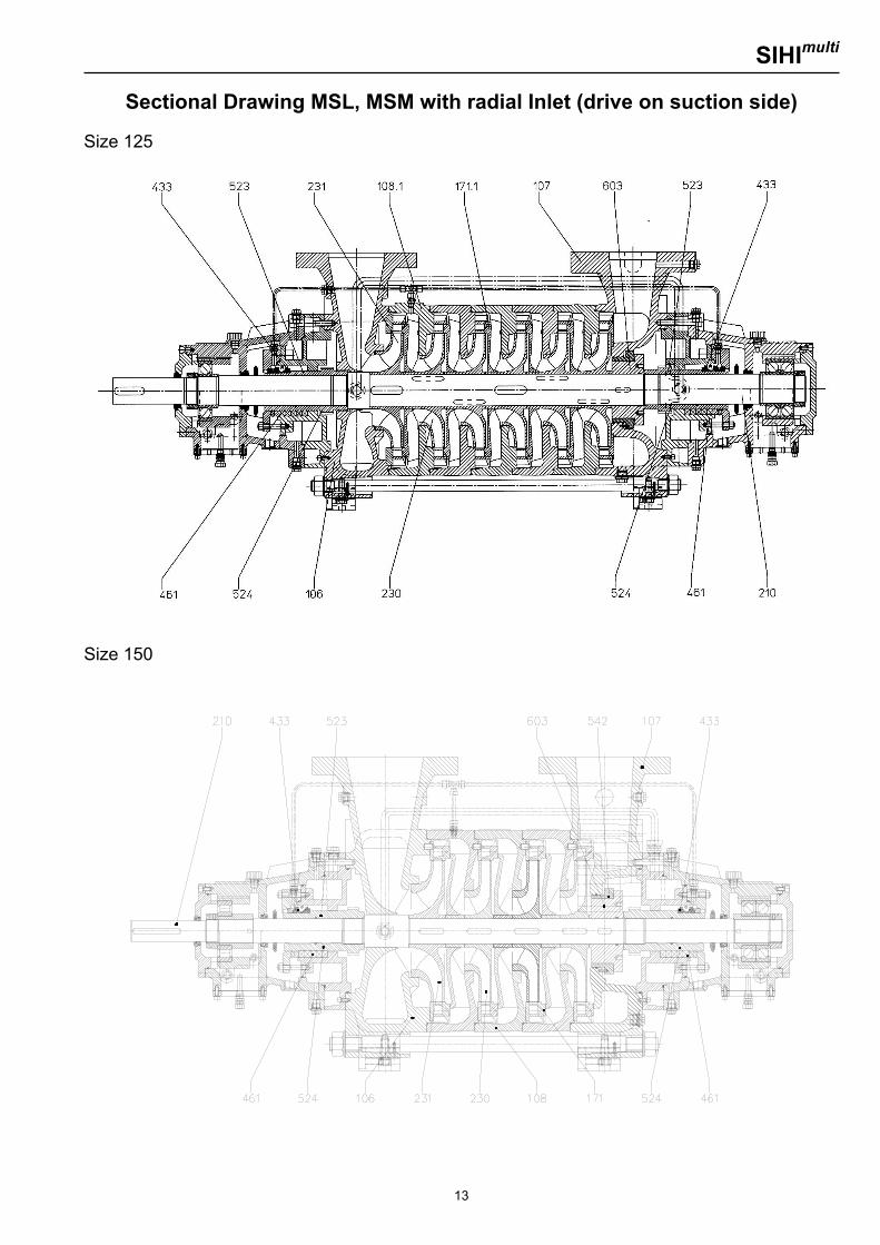
Sectional Drawing MSL, MSM with radial Inlet (drive on suction side) Size 125
Size 150
SIHImulti
14
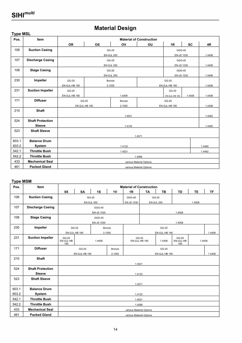
Material Design Type MSL
Pos. Item Material of Construction
OR OS OV OU 1R SC 4R 106 Suction Casing GG-25 GGG-40
EN-GJL 250 EN-JS 1030 1.4408
107 Discharge Casing GG-25 GGG-40
EN-GJL 250 EN-JS 1030 1.4408
108 Stage Casing GG-25 GGG-40
EN-GJL 250 EN-JS 1030 1.4408
230 Impeller GG-25 Bronze GG-25
EN-GJL-HB 195 2.1050 EN-GJL-HB 195 1.4408
231 Suction Impeller GG-25 GG-25
EN-GJL-HB 195 1.4409 EN-GJL-HB 195 1.4408 1.4408
171 Diffuser GG-25 Bronze GG-25
EN-GJL-HB 195 2.1050 EN-GJL-HB 195 1.4408
210 Shaft
1.4021 1.4462
524 Shaft Protection
Sleeve 1.4122 1.4460
523 Shaft Sleeve
1.4571
603.1 Balance Drum
603.2 System 1.4122 1.4460
542.1 Throttle Bush 1.4021 1.4462
542.2 Throttle Bush 1.4088
433 Mechanical Seal various Material Options
461 Packed Gland various Material Options
Type MSM Pos. Item Material of Construction
0X SA 1S 1V 1R TA TB TD TE TF 106 Suction Casing GG-25 GGG-40 GG-25
EN-GJL 250 EN-JS 1030 EN-GJL 250 1.4008
107 Discharge Casing GGG-40
EN-JS 1030 1.4008
108 Stage Casing GGG-40
EN-JS 1030 1.4008
230 Impeller GG-25 Bronze GG-25
EN-GJL-HB 195 2.1050 EN-GJL-HB 195 1.4409
231 Suction Impeller GG-25 GG-25 GG-25 EN-GJL-HB
195 1.4408 EN-GJL-HB 195 1.4408 EN-GJL-HB
195 1.4408
171 Diffuser GG-25 Bronze GG-25
EN-GJL-HB 195 2.1050 EN-GJL-HB 195 1.4408
210 Shaft
1.4021
524 Shaft Protection Sleeve
1.4122
523 Shaft Sleeve
1.4571
603.1 603.2
Balance Drum System
1.4122
542.1 Throttle Bush 1.4021
542.2 Throttle Bush 1.4088
433 Mechanical Seal various Material Options
461 Packed Gland various Material Options
SIHImulti
15
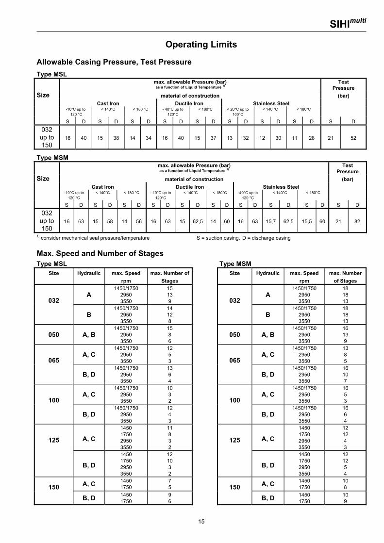
Operating Limits Allowable Casing Pressure, Test Pressure Type MSL max. allowable Pressure (bar)
as a function of Liquid Temperature 1) Test
Pressure Size material of construction (bar) Cast Iron Ductile Iron Stainless Steel
-10°C up to 120 °C
< 140°C
< 180 °C
- 40°C up to 120°C
< 180°C
< 20°C up to 100°C
< 140 °C
< 180°C
S D S D S D S D S D S D S D S D S D 032 up to 150
16 40 15 38 14 34 16 40 15 37 13 32 12 30 11 28 21 52
Type MSM max. allowable Pressure (bar)
as a function of Liquid Temperature 1) Test
Pressure Size material of construction (bar) Cast Iron Ductile Iron Stainless Steel -10°C up to
120 °C < 140°C
< 180 °C
- 10°C up to
120°C < 140°C
< 180°C
-40°C up to
120 °C < 140°C
< 180°C
S D S D S D S D S D S D S D S D S D S D 032 up to 150
16 63 15 58 14 56 16 63 15 62,5 14 60 16 63 15,7 62,5 15,5 60 21 82
1) consider mechanical seal pressure/temperature S = suction casing, D = discharge casing Max. Speed and Number of Stages Type MSL Type MSM
Size Hydraulic max. Speed rpm
max. Number of Stages
Size Hydraulic max. Speed rpm
max. Number of Stages
032 A
1450/1750 2950 3550
15 13 9
032 A
1450/1750 2950 3550
18 18 13
B
1450/1750 2950 3550
14 12 8
B
1450/1750 2950 3550
18 18 13
050 A, B 1450/1750
2950 3550
15 8 6
050 A, B
1450/1750 2950 3550
16 13 9
065 A, C
1450/1750 2950 3550
12 5 3
065 A, C
1450/1750 2950 3550
13 8 5
B, D
1450/1750 2950 3550
13 6 4
B, D
1450/1750 2950 3550
16 10 7
100 A, C
1450/1750 2950 3550
10 3 2
100 A, C
1450/1750 2950 3550
16 5 3
B, D
1450/1750 2950 3550
12 4 3
B, D
1450/1750 2950 3550
16 6 4
125 A, C
1450 1750 2950 3550
11 8 3 2
125 A, C
1450 1750 2950 3550
12 12 4 3
B, D
1450 1750 2950 3550
12 10 3 2
B, D
1450 1750 2950 3550
12 12 5 4
150 A, C 1450 1750
7 5
150 A, C 1450
1750 10 8
B, D 1450 1750
9 6
B, D 1450 1750
10 9
SIHImulti
16
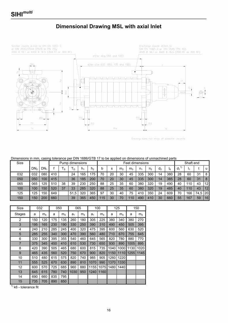
Dimensional Drawing MSL with axial Inlet
Dimensions in mm, casing tolerance per DIN 1686/GTB 17 to be applied on dimensions of unmachined parts
Size Pump dimensions Feet dimensions Shaft end DN2 DN1 f TS TD h1 h2 b s m2 m3 n1 n2 d2 l6 d1
1) l1 t u
032 032 080 410 24 165 175 70 20 30 45 335 300 14 380 28 60 31 8050 050 100 415 36 185 200 70 20 30 45 335 300 14 385 28 60 31 8065 065 125 510 38 39 230 250 88 25 35 60 380 320 19 490 40 110 43 12100 100 150 520 37 33 285 320 88 25 35 60 380 320 19 485 40 110 43 12125 125 150 649 51,5 320 365 97 30 40 75 410 350 24 609 70 166 74,5 20150 150 200 660 39 365 450 115 30 70 110 490 410 30 660 55 167 59 16
Size 032 050 065 100 125 150
Stages a m4 a m4 a1 m4 a1 m4 a m4 a m4
2 150 120 175 135 260 180 305 225 380 340 380 2703 195 165 230 190 330 250 390 310 490 450 505 3954 240 210 285 245 400 320 475 395 600 560 630 5205 285 255 340 300 470 390 560 480 710 670 755 6456 330 300 395 355 540 460 645 565 820 780 880 7707 375 345 450 410 610 530 730 650 930 890 1005 8958 420 390 505 465 680 600 815 735 1040 1000 1130 10209 465 435 560 520 750 670 900 820 1150 1110 1255 1145
10 510 480 615 575 820 740 985 905 1260 1220 11 555 525 670 630 890 810 1070 990 1370 1330 12 600 570 725 685 960 880 1155 1075 1480 1440 13 645 615 780 740 1030 950 1240 1160 14 690 660 835 795 15 735 705 890 850
1) k6 - tolerance fit
SIHImulti
17
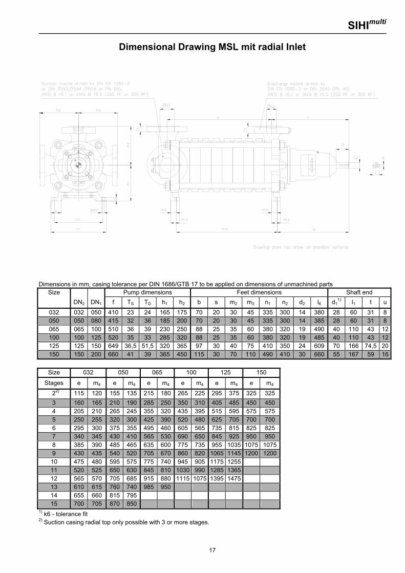
Dimensional Drawing MSL mit radial Inlet
Dimensions in mm, casing tolerance per DIN 1686/GTB 17 to be applied on dimensions of unmachined parts
Size Pump dimensions Feet dimensions Shaft end DN2 DN1 f TS TD h1 h2 b s m2 m3 n1 n2 d2 l6 d1
1) l1 t u
032 032 050 410 23 24 165 175 70 20 30 45 335 300 14 380 28 60 31 8 050 050 080 415 32 36 185 200 70 20 30 45 335 300 14 385 28 60 31 8 065 065 100 510 36 39 230 250 88 25 35 60 380 320 19 490 40 110 43 12100 100 125 520 35 33 285 320 88 25 35 60 380 320 19 485 40 110 43 12125 125 150 649 36,5 51,5 320 365 97 30 40 75 410 350 24 609 70 166 74,5 20150 150 200 660 41 39 365 450 115 30 70 110 490 410 30 660 55 167 59 16
Size 032 050 065 100 125 150
Stages e m4 e m4 e m4 e m4 e m4 e m4
22) 115 120 155 135 215 180 265 225 295 375 325 325 3 160 165 210 190 285 250 350 310 405 485 450 450 4 205 210 265 245 355 320 435 395 515 595 575 575 5 250 255 320 300 425 390 520 480 625 705 700 700 6 295 300 375 355 495 460 605 565 735 815 825 825 7 340 345 430 410 565 530 690 650 845 925 950 950 8 385 390 485 465 635 600 775 735 955 1035 1075 10759 430 435 540 520 705 670 860 820 1065 1145 1200 120010 475 480 595 575 775 740 945 905 1175 1255 11 520 525 650 630 845 810 1030 990 1285 1365 12 565 570 705 685 915 880 1115 1075 1395 1475 13 610 615 760 740 985 950 14 655 660 815 795 15 700 705 870 850
1) k6 - tolerance fit 2) Suction casing radial top only possible with 3 or more stages.
SIHImulti
18
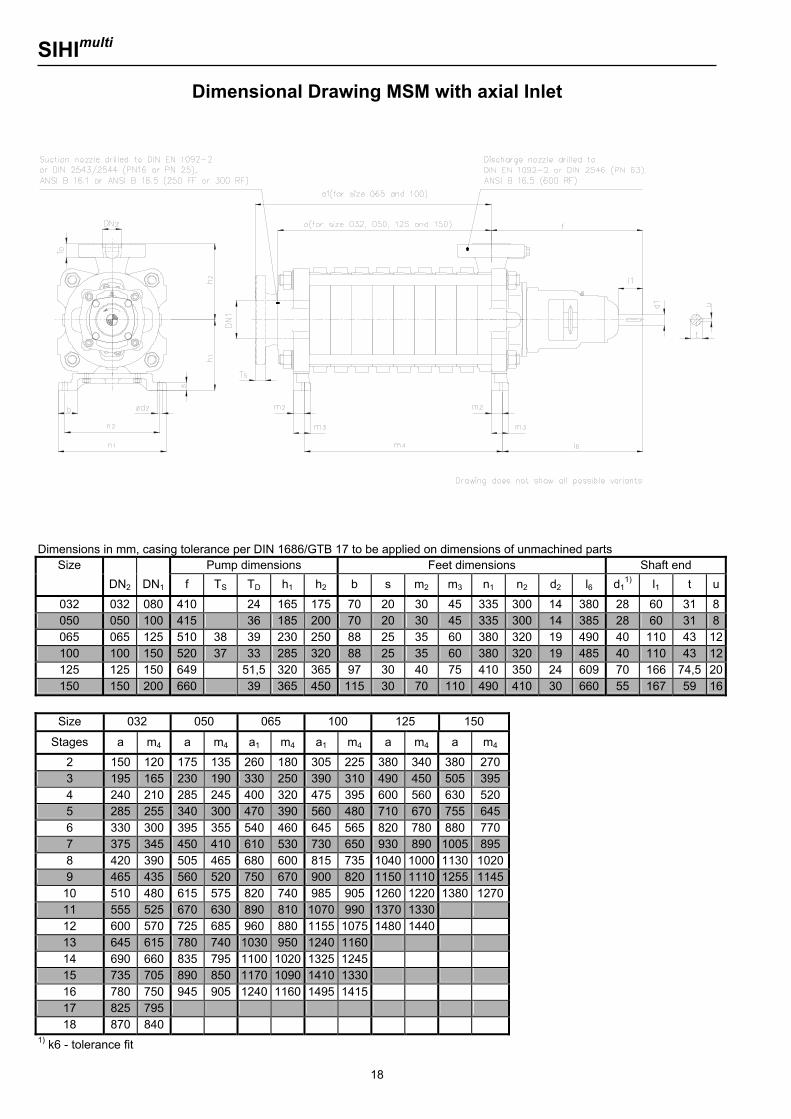
Dimensional Drawing MSM with axial Inlet
Dimensions in mm, casing tolerance per DIN 1686/GTB 17 to be applied on dimensions of unmachined parts
Size Pump dimensions Feet dimensions Shaft end DN2 DN1 f TS TD h1 h2 b s m2 m3 n1 n2 d2 l6 d1
1) l1 t u
032 032 080 410 24 165 175 70 20 30 45 335 300 14 380 28 60 31 8050 050 100 415 36 185 200 70 20 30 45 335 300 14 385 28 60 31 8065 065 125 510 38 39 230 250 88 25 35 60 380 320 19 490 40 110 43 12100 100 150 520 37 33 285 320 88 25 35 60 380 320 19 485 40 110 43 12125 125 150 649 51,5 320 365 97 30 40 75 410 350 24 609 70 166 74,5 20150 150 200 660 39 365 450 115 30 70 110 490 410 30 660 55 167 59 16
Size 032 050 065 100 125 150
Stages a m4 a m4 a1 m4 a1 m4 a m4 a m4
2 150 120 175 135 260 180 305 225 380 340 380 270 3 195 165 230 190 330 250 390 310 490 450 505 395 4 240 210 285 245 400 320 475 395 600 560 630 520 5 285 255 340 300 470 390 560 480 710 670 755 645 6 330 300 395 355 540 460 645 565 820 780 880 770 7 375 345 450 410 610 530 730 650 930 890 1005 895 8 420 390 505 465 680 600 815 735 1040 1000 1130 10209 465 435 560 520 750 670 900 820 1150 1110 1255 1145
10 510 480 615 575 820 740 985 905 1260 1220 1380 127011 555 525 670 630 890 810 1070 990 1370 1330 12 600 570 725 685 960 880 1155 1075 1480 1440 13 645 615 780 740 1030 950 1240 1160 14 690 660 835 795 1100 1020 1325 1245 15 735 705 890 850 1170 1090 1410 1330 16 780 750 945 905 1240 1160 1495 1415 17 825 795 18 870 840
1) k6 - tolerance fit

SIHImulti
19
Dimensional Drawing MSM with radial Inlet
Dimensions in mm, casing tolerance per DIN 1686/GTB 17 to be applied on dimensions of unmachined parts
Size Pump dimensions Feet dimensions Shaft end DN2 DN1 f TS TD h1 h2 b s m2 m3 n1 n2 d2 l6 d1
1) l1 t u
032 032 050 410 23 24 165 175 70 20 30 45 335 300 14 380 28 60 31 8 050 050 080 415 32 36 185 200 70 20 30 45 335 300 14 385 28 60 31 8 065 065 100 510 36 39 230 250 88 25 35 60 380 320 19 490 40 110 43 12100 100 125 520 35 33 285 320 88 25 35 60 380 320 19 485 40 110 43 12125 125 200 649 36,5 51,5 320 365 97 30 40 75 410 350 24 609 70 166 74,5 20150 150 200 660 41 39 365 450 115 30 70 110 490 410 30 660 55 167 59 16
Size 032 050 065 100 125 150
Stages e m4 e m4 e m4 e m4 e m4 e m4
22) 115 120 155 135 215 180 265 225 295 375 325 325 3 160 165 210 190 285 250 350 310 405 485 450 450 4 205 210 265 245 355 320 435 395 515 595 575 575 5 250 255 320 300 425 390 520 480 625 705 700 700 6 295 300 375 355 495 460 605 565 735 815 825 825 7 340 345 430 410 565 530 690 650 845 925 950 950 8 385 390 485 465 635 600 775 735 955 1035 1075 10759 430 435 540 520 705 670 860 820 1065 1145 1200 120010 475 480 595 575 775 740 945 905 1175 1255 1325 132511 520 525 650 630 845 810 1030 990 1285 1365 1450 145012 565 570 705 685 915 880 1115 1075 1395 1475 1575 157513 610 615 760 740 985 950 1200 1160 14 655 660 815 795 1055 1020 1285 1245 15 700 705 870 850 1125 1090 1370 1330 16 745 750 925 905 1195 1160 1455 1415 17 790 795 18 835 840
1) k6 - tolerance fit 2) Suction casing radial top only possible with 3 and more stages.
SIHImulti
20
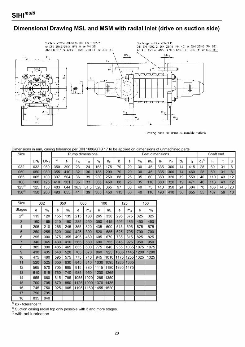
Dimensional Drawing MSL and MSM with radial Inlet (drive on suction side)
Dimensions in mm, casing tolerance per DIN 1686/GTB 17 to be applied on dimensions of unmachined parts
Size Pump dimensions Feet dimensions Shaft end
DN2 DN1 f f1 TS TD h1 h2 b s m2 m3 n1 n2 d2 l4 d11) l1 t u
032 032 050 350 390 23 24 165 175 70 20 30 45 335 300 14 415 28 60 31 8 050 050 080 355 410 32 36 185 200 70 20 30 45 335 300 14 460 28 60 31 8 065 065 100 397 504 36 39 230 250 88 25 35 60 380 320 19 559 40 110 43 12100 100 125 410 501 35 33 365 450 88 25 35 110 380 320 19 471 40 113 43 12
1253) 125 150 483 644 36,5 51,5 320 365 97 30 40 75 410 350 24 604 70 166 74,5 201503) 150 200 493 655 41 39 365 450 115 30 40 110 490 410 30 655 55 167 59 16
Size 032 050 065 100 125 150
Stages e m4 e m4 e m4 e m4 e m4 e m4
22) 115 120 155 135 215 180 265 330 295 375 325 325 3 160 165 210 190 285 250 350 415 405 485 450 450 4 205 210 265 245 355 320 435 500 515 595 575 575 5 250 255 320 300 425 390 520 585 625 705 700 700 6 295 300 375 355 495 460 605 670 735 815 825 825 7 340 345 430 410 565 530 690 755 845 925 950 950 8 385 390 485 465 635 600 775 840 955 1035 1075 10759 430 435 540 520 705 670 860 925 1065 1145 1200 120010 475 480 595 575 775 740 945 1010 1175 1255 1325 132511 520 525 650 630 845 810 1030 1095 1285 1365 12 565 570 705 685 915 880 1115 1180 1395 1475 13 610 615 760 740 985 950 1200 1265 14 655 660 815 795 1055 1020 1285 1350 15 700 705 870 850 1125 1090 1370 1435 16 745 750 925 905 1195 1160 1455 1520 17 790 795 18 835 840
1) k6 - tolerance fit 2) Suction casing radial top only possible with 3 and more stages. 3) with oel lubrication
SIHImulti
21
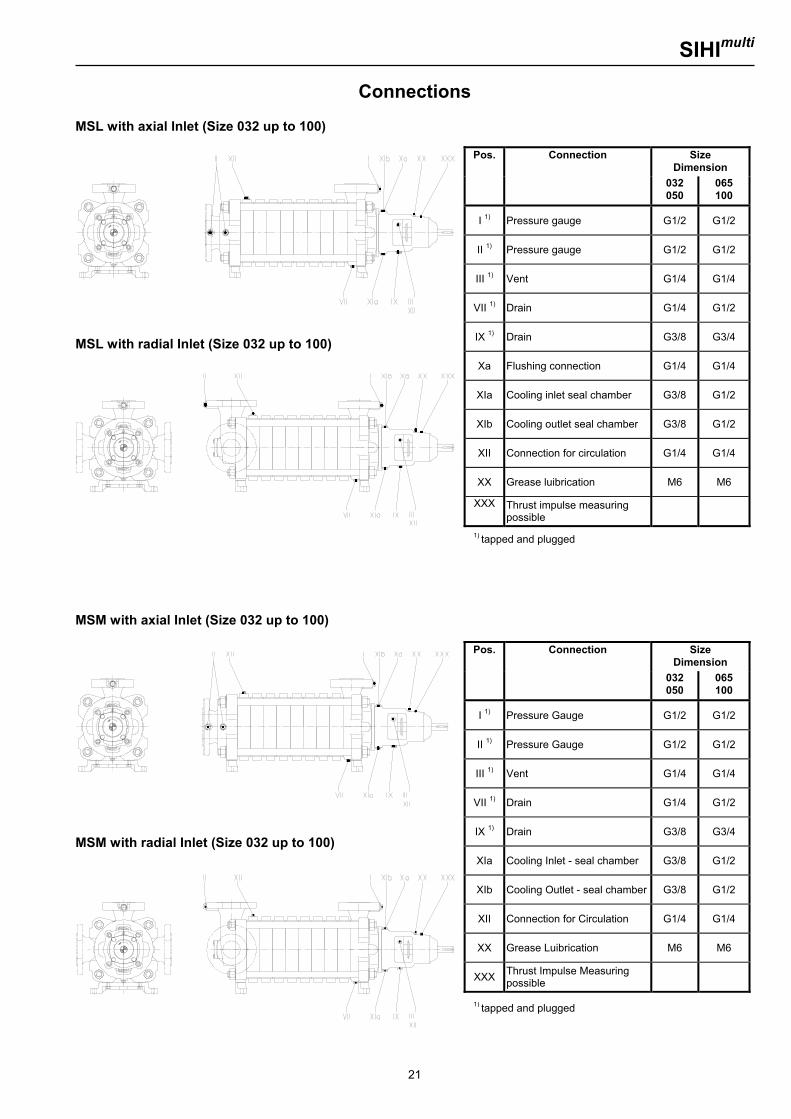
Connections MSL with axial Inlet (Size 032 up to 100)
MSL with radial Inlet (Size 032 up to 100)
MSM with axial Inlet (Size 032 up to 100)
MSM with radial Inlet (Size 032 up to 100)
Pos. Connection Size Dimension
032 050
065 100
I 1) Pressure gauge G1/2 G1/2
II 1) Pressure gauge G1/2 G1/2
III 1) Vent G1/4 G1/4
VII 1) Drain G1/4 G1/2
IX 1) Drain G3/8 G3/4
Xa Flushing connection G1/4 G1/4
XIa Cooling inlet seal chamber G3/8 G1/2
XIb Cooling outlet seal chamber G3/8 G1/2
XII Connection for circulation G1/4 G1/4
XX Grease luibrication M6 M6
XXX Thrust impulse measuring possible
Pos. Connection Size Dimension
032 050
065 100
I 1) Pressure Gauge G1/2 G1/2
II 1) Pressure Gauge G1/2 G1/2
III 1) Vent G1/4 G1/4
VII 1) Drain G1/4 G1/2
IX 1) Drain G3/8 G3/4
XIa Cooling Inlet - seal chamber G3/8 G1/2
XIb Cooling Outlet - seal chamber G3/8 G1/2
XII Connection for Circulation G1/4 G1/4
XX Grease Luibrication M6 M6
XXX Thrust Impulse Measuring possible
1) tapped and plugged
1) tapped and plugged
SIHImulti
22
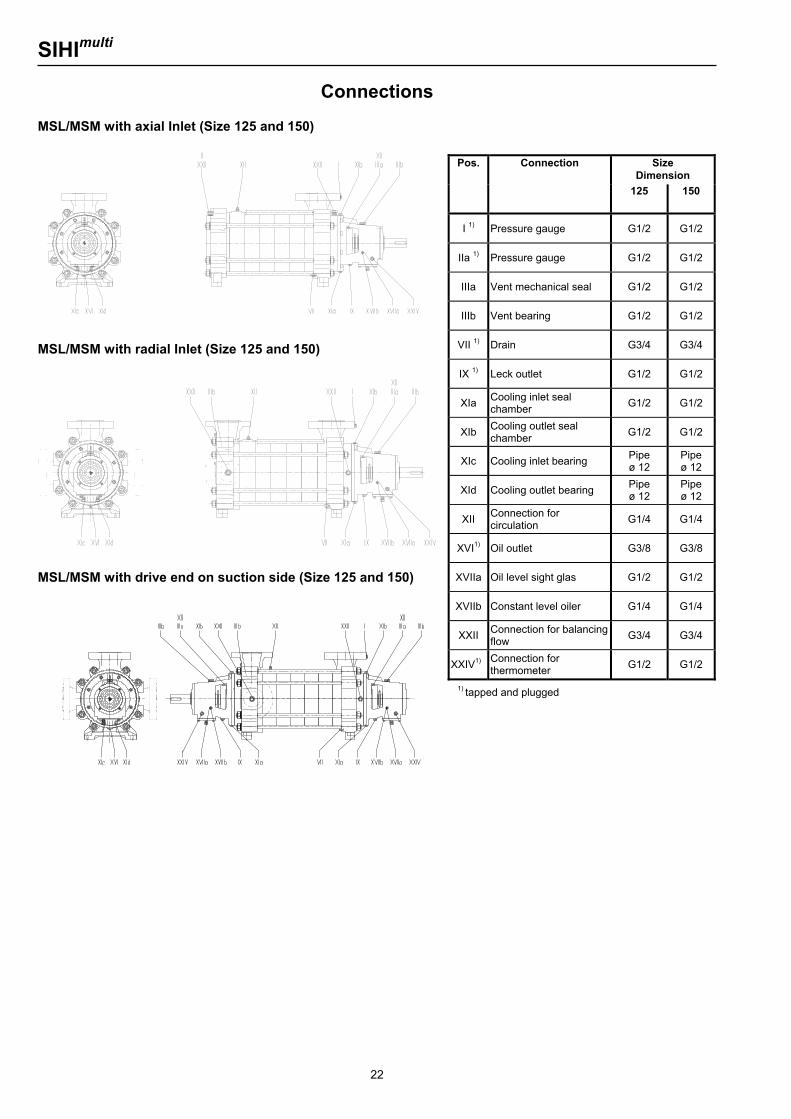
Connections MSL/MSM with axial Inlet (Size 125 and 150)
MSL/MSM with radial Inlet (Size 125 and 150)
MSL/MSM with drive end on suction side (Size 125 and 150)
Pos. Connection Size Dimension
125 150
I 1) Pressure gauge G1/2 G1/2
IIa 1) Pressure gauge G1/2 G1/2
IIIa Vent mechanical seal G1/2 G1/2
IIIb Vent bearing G1/2 G1/2
VII 1) Drain G3/4 G3/4
IX 1) Leck outlet G1/2 G1/2
XIa Cooling inlet seal chamber G1/2 G1/2
XIb Cooling outlet seal chamber G1/2 G1/2
XIc Cooling inlet bearing Pipe ø 12
Pipe ø 12
XId Cooling outlet bearing Pipe ø 12
Pipe ø 12
XII Connection for circulation G1/4 G1/4
XVI1) Oil outlet G3/8 G3/8
XVIIa Oil level sight glas G1/2 G1/2
XVIIb Constant level oiler G1/4 G1/4
XXII Connection for balancing flow G3/4 G3/4
XXIV1) Connection for thermometer G1/2 G1/2
1) tapped and plugged
SIHImulti
23
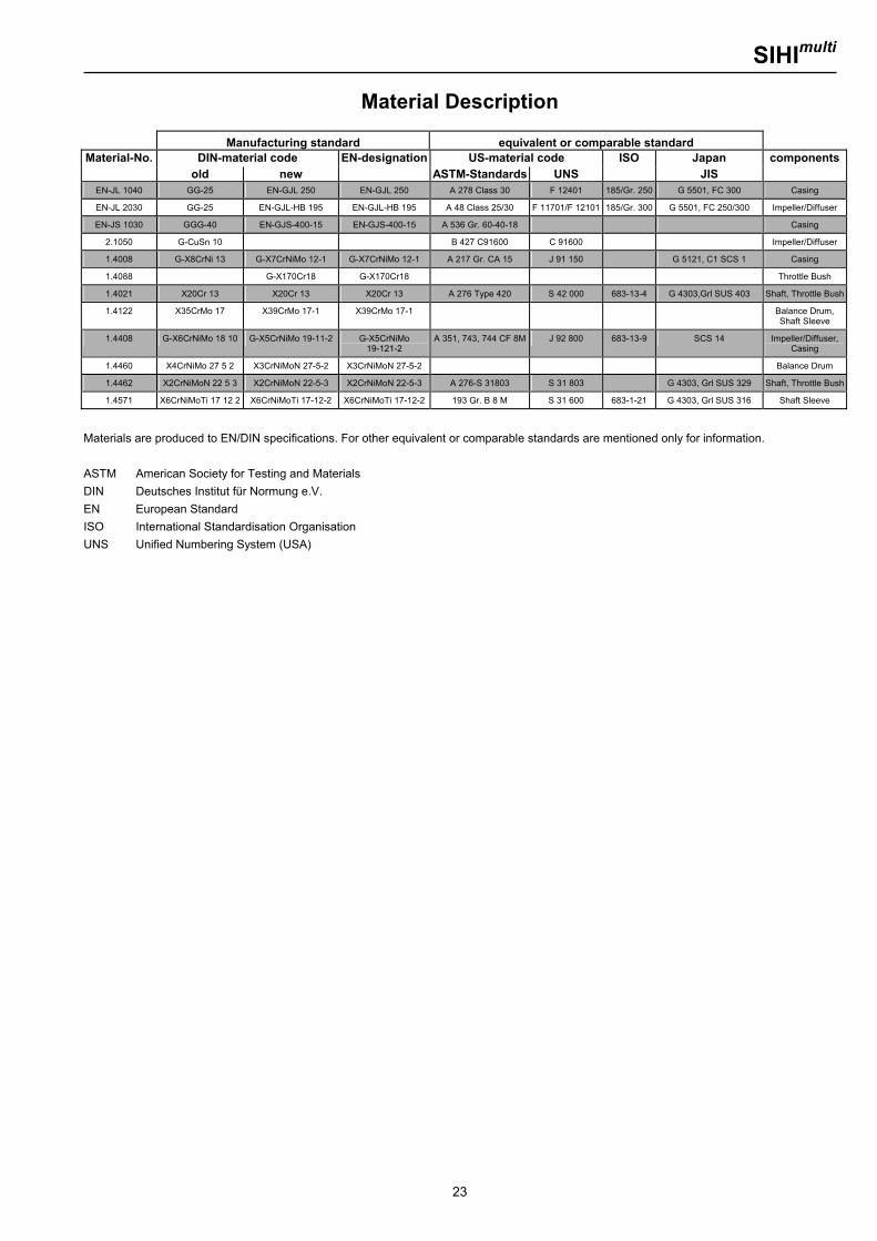
Material Description
Manufacturing standard equivalent or comparable standard Material-No. DIN-material code EN-designation US-material code ISO Japan components
old new ASTM-Standards UNS JIS EN-JL 1040 GG-25 EN-GJL 250 EN-GJL 250 A 278 Class 30 F 12401 185/Gr. 250 G 5501, FC 300 Casing
EN-JL 2030 GG-25 EN-GJL-HB 195 EN-GJL-HB 195 A 48 Class 25/30 F 11701/F 12101 185/Gr. 300 G 5501, FC 250/300 Impeller/Diffuser
EN-JS 1030 GGG-40 EN-GJS-400-15 EN-GJS-400-15 A 536 Gr. 60-40-18 Casing
2.1050 G-CuSn 10 B 427 C91600 C 91600 Impeller/Diffuser
1.4008 G-X8CrNi 13 G-X7CrNiMo 12-1 G-X7CrNiMo 12-1 A 217 Gr. CA 15 J 91 150 G 5121, C1 SCS 1 Casing
1.4088 G-X170Cr18 G-X170Cr18 Throttle Bush
1.4021 X20Cr 13 X20Cr 13 X20Cr 13 A 276 Type 420 S 42 000 683-13-4 G 4303,Grl SUS 403 Shaft, Throttle Bush
1.4122 X35CrMo 17 X39CrMo 17-1 X39CrMo 17-1 Balance Drum, Shaft Sleeve
1.4408 G-X6CrNiMo 18 10 G-X5CrNiMo 19-11-2 G-X5CrNiMo 19-121-2
A 351, 743, 744 CF 8M J 92 800 683-13-9 SCS 14 Impeller/Diffuser,Casing
1.4460 X4CrNiMo 27 5 2 X3CrNiMoN 27-5-2 X3CrNiMoN 27-5-2 Balance Drum
1.4462 X2CrNiMoN 22 5 3 X2CrNiMoN 22-5-3 X2CrNiMoN 22-5-3 A 276-S 31803 S 31 803 G 4303, Grl SUS 329 Shaft, Throttle Bush
1.4571 X6CrNiMoTi 17 12 2 X6CrNiMoTi 17-12-2 X6CrNiMoTi 17-12-2 193 Gr. B 8 M S 31 600 683-1-21 G 4303, Grl SUS 316 Shaft Sleeve
Materials are produced to EN/DIN specifications. For other equivalent or comparable standards are mentioned only for information. ASTM American Society for Testing and Materials DIN Deutsches Institut für Normung e.V. EN European Standard ISO International Standardisation Organisation UNS Unified Numbering System (USA)
SIHImulti
24
Sterling SIHI GmbH Werk Ludwigshafen Halbergstr. 1, D-67061 Ludwigshafen, Germany Telefon +49 (0)621 56 12 - 0 Telefax +49 (0)621 56 12 - 209