Embed Size (px)
Citation preview
Silk Protein as a Biomaterial for Tissue Engineering Application: Theoretical and
Experimental Study
A Thesis
Submitted to the Faculty
of
Drexel University
by
Milind Ramesh Gandhi
in Partial Fulfillment of the
Requirements for the Degree
of
Doctor of Philosophy
December 2006

ii
ACKNOWLEDGEMENTS
I will like to take few moments thanking everyone for helping me throughout. First of all
I thank my mother, Dr. Renuka Gandhi and my father, Dr. Ramesh Gandhi for believing
in me and supporting my decision to come to Drexel for Ph.D.
I would like to express my gratitude to my mentor, Prof. Frank K. Ko. Under his
supervision I was able to grow as an engineer. Being trained as a medical doctor I had
limited knowledge of engineering and biomaterials. Dr. Ko guided me throughout my
studies.
I would like to acknowledge the help of my committee members, Dr. Donald L.
McEachron, Dr. Peter I. Lelkes, Dr. Fred D. Allen and Dr. Andrzej Fertala. Special
thanks to the committee members from Biomedical Sciences, Engineering & Health
Systems Department, Dr. McEachron, Dr. Lelkes and Dr. Allen for pushing me to carry
out the cell-matrix interaction study on my scaffolds. I learnt a lot from that experience.
I am also grateful for the financial support provided by the funding agencies,
Pennsylvania Nanotechnoly Institute, Taiwan Textile Research Institute and Nexia
Biotechnologies.
I would also like to thank the present and past members of the Fibrous Materials
Laboratory, Heejae Yang, Donia El-Khamy , Dr. Hoa Lam, Dr. Jonathan Ayutsede, Nick
Titchenal, Dr. Jason Lyons, Sharaili Rao, David Heldt, Dr. Afaf El-Aufy, and Jennifer
Atchinson. Thank you all for all your suggestions and for being with me not only during
my good times but also bad ones. I am grateful to the visiting scholars, Dr. Sachiko
Sukigara and Dr. Xiong Jie for their help.

iii
I wish to thank my friends from Biomed, Dr. Michele Cox, Mai Bui, Nancy Robinson
and Dr. Amir Rezvan. I met you guys for the first time when I came to Drexel. You have
always supported me since then. I thank you all for being such loyal friends. Special
thanks to Michele’s mom, Mrs. Cynthia Cox for being a mom!
I am grateful to Dr. Sun from Mechanical Engineering for allowing me to use his lab for
cell culture work. Special thanks to Lauren Shor for helping me out with osteoblasts
culture.
I would like to extend my thanks to the ever helping staff of Materials and Biomed
departments, especially Judy Trachtman and Lisa Williams.
I am also thankful to all my other friends, Mary Sullivan, Amanda Hunt, Elaine Steinke,
Maria Pia Rossi, Jonathan Thomas and Jackie. I am grateful to all my family members in
United States as well as back in India for all the support and encouragement. Special
thanks to my brother, Sachin Gandhi and his wife Roma Bhansali.
Lastly, I will like to thank my ex-wife, Payal Nanavati for being a good friend. I thank
her family members for their emotional support and understanding.
iv
TABLE OF CONTENTS
LIST OF TABLES………………………………………………………………………ix
LIST OF FIGURES………………………………………………………………………x
ABSTRACT……………………………………………………………………………xvi
1. INTRODUCTION…………………………………………………………………….1
2. BACKGROUND AND LITERATURE REVIEW…………………………………...5
2.1. Types of Silk Protein……………………………………………………………..6
2.1.1. Silkworm Silk……………………………………………………………..6
2.1.2. Spider Silk…………………………………………………………………7
2.2. Structure and Properties of Silk…………………………………………………..8
2.2.1. Structure of Silk …………………………………………………………..8
2.2.2. Mechanical Properties……………………………………………………..9
2.2.3. Biological Properties……………………………………………………..10
2.3. Production of Silk Fibers………………………………………………………..12
2.3.1. Natural Silk Spinning Process…………………………………………...12
2.3.2. Artificial Fiber formation using Regenerated Silk………………………13
2.3.3. Electrospinning…………………………………………………………..16
2.4. Genetic Engineering…………………………………………………………….18
2.4.1. Recombinant Silkworm and Spider Silk…………………………………18
2.4.2. Hybrid Silk.………………………………………………………………21
2.4.3. Transgenic Spider Silk …………………………………………………..22
2.5. Biomedical Applications of Silk………………………………………………...23
v
2.5.1. Tissue Engineering……………………………………………………….23
2.5.2. Drug Delivery……………………………………………………………24
2.6. Bone Tissue Engineering………………………………………………………..25
2.6.1. Structure and Functions of Bone…………………………………………25
2.6.2. Bone Tissue Engineering Methods………………………………………27
3. RESEARCH DESIGN AND OBJECTIVES………………………………………...30
3.1. Structural Changes in Natural and Regenerated Silk…………………………...31
3.2. Nanofibrous Scaffolds from Silkworm Silk ……………………………………31
3.3. Modification of Mechanical Properties of Silkworm Silk Nanofibers …………32
3.3.1. Post Spinning Modifications……………………………………………..32
3.3.2. Co-electrospinning with Carbon Nanotubes……………………………..33
3.3.3. Co-electrospinning with Collagen and Polylactic-co-glycolic Acid ……34
3.4. Nanofibrous Scaffolds from Spider Silk and Carbon Nanotubes………………34
3.5. Cell-Scaffolds Interaction………………………………………………………34
4. STRUCTURAL CHANGES IN NATURAL AND REGENERATED SILK ……...35
4.1. Introduction……………………………………………………………………...35
4.2. Materials and Methods………………………………………………………….38
4.2.1. Molecular Dynamics Simulation of Natural Silk Spinning Process……..38
4.2.2. Molecular Dynamics Simulation of Regenerated Silk …………………..40
4.3. Results…………………………………………………………………………...41
4.3.1. Natural Silk Spinning Process…………………………………………...41
4.3.2. Regenerated Silk Process………………………………………………...46
4.4. Summary…………………………………………………...................................55
vi
5. NANOFIBROUS SCAFFOLDS FROM SILKWORM SILK………………………57
5.1. Introduction ……………………………………………………………..............57
5.2. Materials and Methods………………………………………………….............59
5.2.1. Regenerated Silk and Spinning Dope Preparation ………………………59
5.2.2. Electrospinning Process Optimization and Characterization ……………59
5.2.3. Cell-scaffolds Interaction………………………………………………...62
5.3. Results………………………………………………….......................................65
5.3.1. Fiber Diameter Distribution ……………………………..........................65
5.3.2. FT-IR Spectroscopy…………………………….......................................70
5.3.3. Raman Spectroscopy……………………………......................................71
5.3.4. Wide Angle X-ray Diffraction…………………………….......................73
5.3.5. Mechanical Properties……………………………....................................74
5.3.6. Cell Proliferation and Differentiation……………………………............77
5.4. Summary……………………………...................................................................82
6. MODIFICATION OF MECHANICAL PROPERTIES OF SILKWORM SILK
NANOFIBERS ……………………………………………………………………...84
6.1. Introduction ……………………………..............................................................84
6.2. Materials and Methods………………………………………………………….86
6.2.1. Post spinning treatment …………………………………………………86
6.2.2. Co-electrospinning Silkworm Silk and Carbon Nanotubes ……………..88
6.2.3. Co-electrospinning Silkworm Silk, Polylactic-co-glycolic Acid and
Collagen …………………………………………………………………90
6.2.4. Cell-scaffolds Interaction………………………………………………..90
vii
6.3. Results…………………………….......................................................................90
6.3.1. Effect of Methanol on the Structure of Silk Nanofibers………………....90
6.3.2. Effect of Carbon Nanotubes on the Structure of Silk Nanofibers……….94
6.3.3. Effect of Methanol on Mechanical Properties…………………………...97
6.3.4. Effect of Carbon Nanotubes on Mechanical Properties and Electrical
Conductivity…………………………………………………………….101
6.3.5. Effect of Collagen and Polylactic-co-glycolic Acid on Mechanical
Properties……………………………………………………………….105
6.3.6. Cell Proliferation and Differentiation…………………………………..107
6.4. Summary……………………………………………………………………….116
7. NANOFIBROUS SCAFFOLDS FROM SPIDER SILK AND CARBON
NANOTUBES ……………………………………………………………………..117
7.1. Introduction…………………………….............................................................117
7.2. Materials and Methods………………………………………………………...119
7.2.1. Process Optimization and Characterization…………………………….119
7.2.2. Co-electrospinning MaSp1 and Carbon Nanotubes…………………….120
7.2.3. Cell-scaffolds Interaction……………………………………………….120
7.3. Results………………………………………………………………………….121
7.3.1. Fiber Diameter Distribution ……………………………………………121
7.3.2. FT-IR Spectroscopy…………………………………………………….122
7.3.3. Raman Spectroscopy……………………………………………………125
7.3.4. Mechanical and Electrical Properties…………………………………...126
7.3.5. Cell Proliferation and Differentiation…………………………………..129
viii
7.4. Summary……………………………………………………………………….132
8. DISCUSSION AND CONCLUSION……………………………………………...133
9. FUTURE WORK AND SUGGESTIONS………………………………………….138
9.1. Silk Sponges …………………………………………………………………..138
9.2. Silk Microspheres……………………………………………………………...142
LIST OF REFERENCES……………………………………………………………….145
APPENDIX……………………………………………………………………………..156
VITA……………………………………………………………………………………159
ix
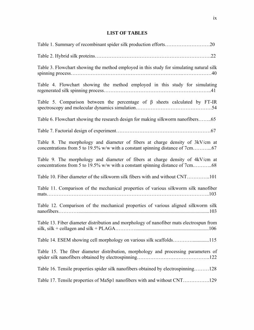
LIST OF TABLES Table 1. Summary of recombinant spider silk production efforts………………………20 Table 2. Hybrid silk proteins…………………………………………………………….22 Table 3. Flowchart showing the method employed in this study for simulating natural silk spinning process………………………………………………………….………………40 Table 4. Flowchart showing the method employed in this study for simulating regenerated silk spinning process………………………………………………………..41 Table 5. Comparison between the percentage of β sheets calculated by FT-IR spectroscopy and molecular dynamics simulation……………………………………….54 Table 6. Flowchart showing the research design for making silkworm nanofibers……..65 Table 7. Factorial design of experiment…………………………………………………67 Table 8. The morphology and diameter of fibers at charge density of 3kV/cm at concentrations from 5 to 19.5% w/w with a constant spinning distance of 7cm………...67 Table 9. The morphology and diameter of fibers at charge density of 4kV/cm at concentrations from 5 to 19.5% w/w with a constant spinning distance of 7cm.………..68 Table 10. Fiber diameter of the silkworm silk fibers with and without CNT…………..101 Table 11. Comparison of the mechanical properties of various silkworm silk nanofiber mats……………………………………………………………………………………..103 Table 12. Comparison of the mechanical properties of various aligned silkworm silk nanofibers………….........................................................................................................103 Table 13. Fiber diameter distribution and morphology of nanofiber mats electrospun from silk, silk + collagen and silk + PLAGA…………...........................................................106 Table 14. ESEM showing cell morphology on various silk scaffolds………….............115 Table 15. The fiber diameter distribution, morphology and processing parameters of spider silk nanofibers obtained by electrospinning……………………………………..122 Table 16. Tensile properties spider silk nanofibers obtained by electrospinning………128 Table 17. Tensile properties of MaSp1 nanofibers with and without CNT…………….129
x
LIST OF FIGURES
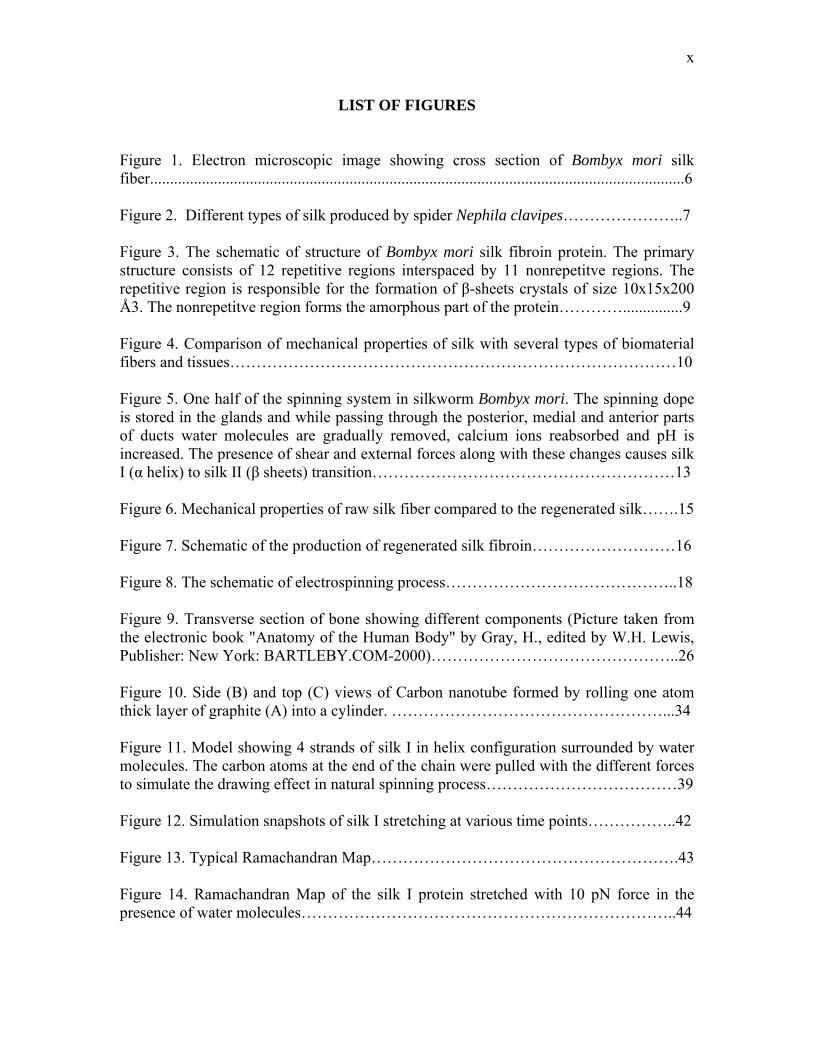
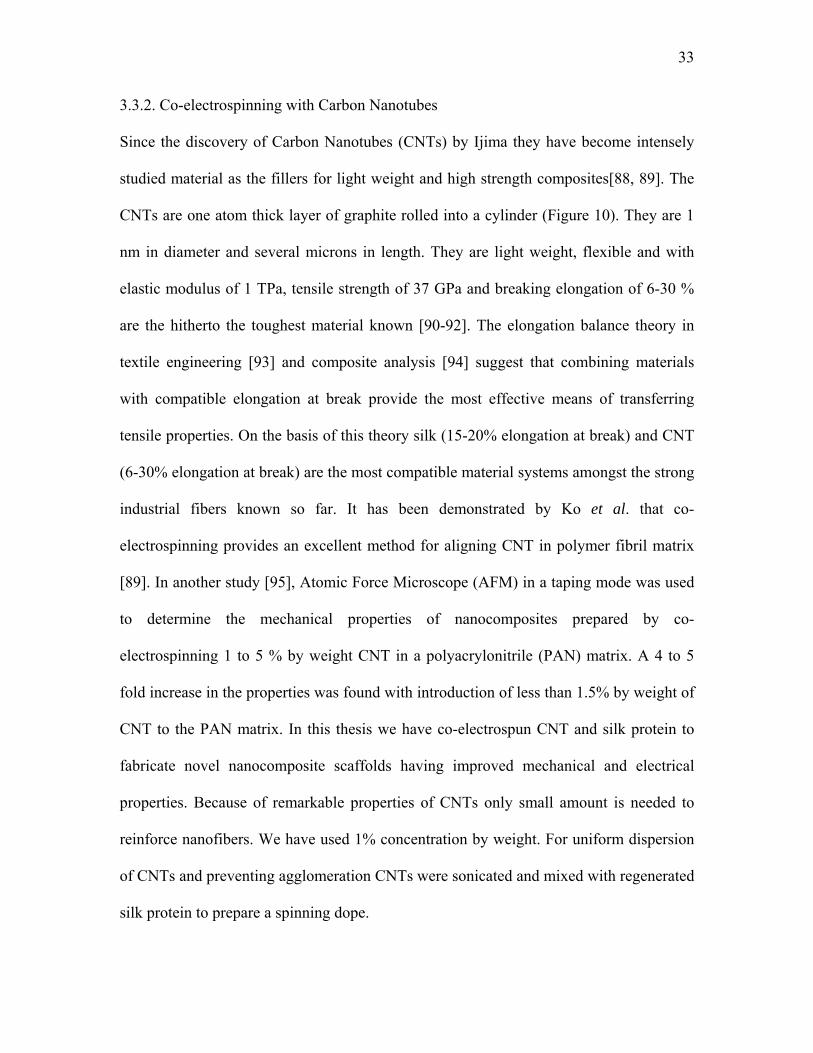
Figure 1. Electron microscopic image showing cross section of Bombyx mori silk fiber......................................................................................................................................6 Figure 2. Different types of silk produced by spider Nephila clavipes…………………..7 Figure 3. The schematic of structure of Bombyx mori silk fibroin protein. The primary structure consists of 12 repetitive regions interspaced by 11 nonrepetitve regions. The repetitive region is responsible for the formation of β-sheets crystals of size 10x15x200 Å3. The nonrepetitve region forms the amorphous part of the protein…………...............9 Figure 4. Comparison of mechanical properties of silk with several types of biomaterial fibers and tissues…………………………………………………………………………10 Figure 5. One half of the spinning system in silkworm Bombyx mori. The spinning dope is stored in the glands and while passing through the posterior, medial and anterior parts of ducts water molecules are gradually removed, calcium ions reabsorbed and pH is increased. The presence of shear and external forces along with these changes causes silk I (α helix) to silk II (β sheets) transition…………………………………………………13 Figure 6. Mechanical properties of raw silk fiber compared to the regenerated silk…….15 Figure 7. Schematic of the production of regenerated silk fibroin………………………16 Figure 8. The schematic of electrospinning process……………………………………..18 Figure 9. Transverse section of bone showing different components (Picture taken from the electronic book "Anatomy of the Human Body" by Gray, H., edited by W.H. Lewis, Publisher: New York: BARTLEBY.COM-2000)………………………………………..26 Figure 10. Side (B) and top (C) views of Carbon nanotube formed by rolling one atom thick layer of graphite (A) into a cylinder. ……………………………………………...34 Figure 11. Model showing 4 strands of silk I in helix configuration surrounded by water molecules. The carbon atoms at the end of the chain were pulled with the different forces to simulate the drawing effect in natural spinning process………………………………39 Figure 12. Simulation snapshots of silk I stretching at various time points……………..42 Figure 13. Typical Ramachandran Map………………………………………………….43 Figure 14. Ramachandran Map of the silk I protein stretched with 10 pN force in the presence of water molecules……………………………………………………………..44
xi
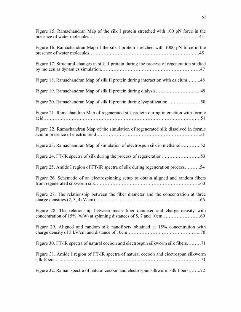
Figure 15. Ramachandran Map of the silk I protein stretched with 100 pN force in the presence of water molecules…………………………………………………………….44 Figure 16. Ramachandran Map of the silk I protein stretched with 1000 pN force in the presence of water molecules…………………………………………………………….45 Figure 17. Structural changes in silk II protein during the process of regeneration studied by molecular dynamics simulation………………………………………………………47 Figure 18. Ramachandran Map of silk II protein during interaction with calcium……...48 Figure 19. Ramachandran Map of silk II protein during dialysis………………………..49 Figure 20. Ramachandran Map of silk II protein during lyophilization…………………50 Figure 21. Ramachandran Map of regenerated silk protein during interaction with formic acid……………………………………………………………………………………….51 Figure 22. Ramachandran Map of the simulation of regenerated silk dissolved in formic acid in presence of electric field…………………………………………………………51 Figure 23. Ramachandran Map of simulation of electrospun silk in methanol………….52 Figure 24. FT-IR spectra of silk during the process of regeneration…………………….53 Figure 25. Amide I region of FT-IR spectra of silk during regeneration process……….54 Figure 26. Schematic of an electrospinning setup to obtain aligned and random fibers from regenerated silkworm silk………………………………………………………….60 Figure 27. The relationship between the fiber diameter and the concentration at three charge densities (2, 3, 4kV/cm) …………………………………………………………66 Figure 28. The relationship between mean fiber diameter and charge density with concentration of 15% (w/w) at spinning distances of 5, 7 and 10cm……………………69 Figure 29. Aligned and random silk nanofibers obtained at 15% concentration with charge density of 3 kV/cm and distance of 10cm………………………………………..70 Figure 30. FT-IR spectra of natural cocoon and electrospun silkworm silk fibers………71 Figure 31. Amide I region of FT-IR spectra of natural cocoon and electrospun silkworm silk fibers…………………………………………………………………………………71 Figure 32. Raman spectra of natural cocoon and electrospun silkworm silk fibers……..72
xii
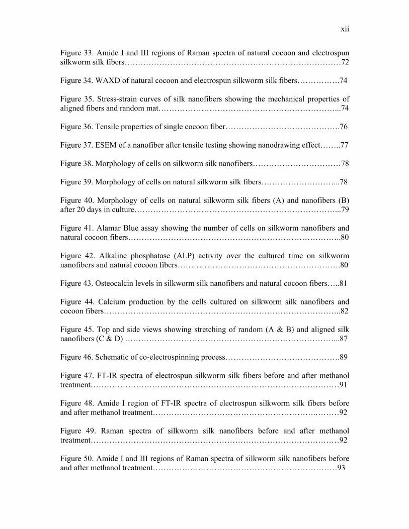
Figure 33. Amide I and III regions of Raman spectra of natural cocoon and electrospun silkworm silk fibers………………………………………………………………………72 Figure 34. WAXD of natural cocoon and electrospun silkworm silk fibers…………….74 Figure 35. Stress-strain curves of silk nanofibers showing the mechanical properties of aligned fibers and random mat…………………………………………………………...74 Figure 36. Tensile properties of single cocoon fiber…………………………………….76 Figure 37. ESEM of a nanofiber after tensile testing showing nanodrawing effect……..77 Figure 38. Morphology of cells on silkworm silk nanofibers……………………………78 Figure 39. Morphology of cells on natural silkworm silk fibers………………………...78 Figure 40. Morphology of cells on natural silkworm silk fibers (A) and nanofibers (B) after 20 days in culture…………………………………………………………………...79 Figure 41. Alamar Blue assay showing the number of cells on silkworm nanofibers and natural cocoon fibers……………………………………………………………………..80 Figure 42. Alkaline phosphatase (ALP) activity over the cultured time on silkworm nanofibers and natural cocoon fibers…………………………………………………….80 Figure 43. Osteocalcin levels in silkworm silk nanofibers and natural cocoon fibers…..81 Figure 44. Calcium production by the cells cultured on silkworm silk nanofibers and cocoon fibers……………………………………………………………………………..82 Figure 45. Top and side views showing stretching of random (A & B) and aligned silk nanofibers (C & D) ……………………………………………………………………...87 Figure 46. Schematic of co-electrospinning process…………………………………….89 Figure 47. FT-IR spectra of electrospun silkworm silk fibers before and after methanol treatment…………………………………………………………………………………91 Figure 48. Amide I region of FT-IR spectra of electrospun silkworm silk fibers before and after methanol treatment…………………………………………………….………92 Figure 49. Raman spectra of silkworm silk nanofibers before and after methanol treatment…………………………………………………………………………………92 Figure 50. Amide I and III regions of Raman spectra of silkworm silk nanofibers before and after methanol treatment……………………………………………………………93
xiii
Figure 51. WAXD of silkworm silk nanofibers before and after methanol treatment…..94 Figure 52. FT-IR spectra of electrospun silkworm silk fibers with and without CNT…..95 Figure 53. Amide I region of FT-IR spectra of electrospun silkworm silk fibers with and without CNT……………………………………………………………………………..95 Figure 54. Raman spectra of silkworm silk nanofibers with and without CNT. The pure CNT spectrum has the characteristic peaks which are observed in the CNT reinforced silk fibers as well……………………………………………………………………………..96 Figure 55. WAXD of silkworm silk nanofibers with and without CNT………………...97 Figure 56. Morphology and diameters of silkworm silk aligned and random nanofibers before and after methanol treatment and stretching……………………………………...98 Figure 57. Effect of methanol and stretching on the tensile properties of silkworm silk nanofiber mat…………………………………………………………………………...100 Figure 58. Effect of methanol and stretching on the tensile properties of silkworm silk aligned nanofiber……………………………………………………………………….100 Figure 59. Effect of CNT on the tensile properties of silkworm silk nanofiber mat…...102 Figure 60. Effect of CNT on the tensile properties of aligned silkworm silk nanofiber………………………………………………………………………………..103 Figure 61. I-V Curves of the natural cocoon fibers, silkworm nanofibers and nanofibers with CNT…………………………………………………………………………………......104 Figure 62. Tensile properties of nanofiber mats electrospun from silk, silk + collagen and silk + PLAGA using HFIP as solvent…………………………………………………..107 Figure 63. Morphology of cells on silkworm silk nanofibers…………………………..108 Figure 64. Morphology of cells on silkworm silk nanofibers with CNT……………….108 Figure 65. Alamar Blue assay showing the number of cells on silkworm nanofibers with and without CNT………………………………………………………………………..109 Figure 66. Alkaline phosphatase (ALP) levels produced by the cells cultured on silkworm nanofibers with and without CNT………………………………………………………110
xiv
Figure 67. Osteocalcin produced by osteoblasts cultured over silkworm silk nanofibers with and without CNT………………………………………………………………….110 Figure 68. Calcium produced by osteoblasts cultured over silkworm silk nanofibers with and without CNT………………………………………………………………………..111 Figure 69. Alamar Blue assay showing number of cells over cultured time on various silk scaffolds………………………………………………………………………………...113 Figure 70. Alkaline phosphatase (ALP) levels produced by cells over various silk scaffolds………………………………………………………………………………...113 Figure 71. Osteocalcin levels over various silk scaffolds………………………………114 Figure 72. Calcium levels over various silk scaffolds………………………………….114 Figure 73. FT-IR spectra of MaSp1 powder and electrospun fibers……………………123 Figure 74. FT-IR spectra of MaSp2 powder and electrospun fibers……………………123 Figure 75. Amide I region of FT-IR of MaSp1 powder and electrospun MaSp1……....124 Figure 76. Amide I region of FT-IR of MaSp2 powder and electrospun MaSp2………125 Figure 77. Raman Spectroscopy of MaSp1 nanofibers with and without CNT………..126 Figure 78. Comparison of the mechanical properties of various spider silk aligned nanofibers………………………………………………………………………………127 Figure 79. Effect of CNT on the tensile properties of aligned MaSp1 nanofiber………128 Figure 80. Morphology of cells on MaSp1 nanofibers…………………………….…...130 Figure 81. Morphology of cells on MaSp1 nanofibers with CNT……………..……….130 Figure 82. Alamar Blue assay showing the number of cells on MaSp1 nanofibers with and without CNT…………………………………………………………………...…...131 Figure 83. Alkaline phosphatase (ALP) levels by cells cultured on MaSp1 with and without CNT ……………..……………..……………..……………..……………..….131 Figure 84. Calcium produced by cells over MaSp1 with and without CNT……………132 Figure 85. Macroscopic examination of silk sponges fabricated from regenerated silk at various concentration in NaOH……………..……………..……………..…………….138
xv
Figure 86. ESEM showing the morphology of sponges fabricated at various concentration……………………………………………………………………………139 Figure 87. Alamar Blue assay showing osteoblasts proliferation on silk sponges……..140 Figure 88. Alkaline phosphatase (ALP) activity by osteoblasts cultured on silk sponges………………..……………..……………..……………..……………..……...140 Figure 89. Osteocalcin levels produced by osteoblasts cultured on silk sponges………141 Figure 90. Calcium produced by osteoblasts on silk sponges………………………….141 Figure 91. ESEM showing the morphology of silk microspheres at various concentrations…………………………………………………………………………..142 Figure 92. Diameter of microspheres at various concentrations……………..…………143
xvi
ABSTRACT
Silk Protein as a Biomaterial for Tissue Engineering Application: Theoretical and Experimental Study
Milind Ramesh Gandhi Advisor: Dr. Frank K Ko
Biocompatible and biodegradable polymeric biomaterials are used to develop biological
matrix or scaffolds not only for Tissue Engineering but also for various biomedical
applications including, wound dressings, membrane filters and drug delivery. Natural
materials are of considerable interest due to their structural properties and superior
biocompatibility. In the world of natural fibers, silk has long been recognized as the
wonder fiber for its unique combination of high strength and rupture elongation. Of
particular interests are the silk fibers from silkworm Bombyx mori and spider Nephila
clavipes. This research deals with fabrication of tissue scaffolds from silk protein. In
particular, we fabricated and characterized silk nanofibers for bone Tissue Engineering
application. Two types of silk protein viz., natural cocoon fibers from silkworm Bombyx
mori and transgenic spider silk from Nephila clavipes were evaluated for the feasibility of
generating nanofibers using electrospinning procedure. The mechanical properties of silk
nanofibers were tailored using various post-spinning methods. Nanocomposite nanofibers
made up of silk and carbon nanotube (CNT) were fabricated with the intension of
improving mechanical and electrical properties of the scaffolds. The biocompatibility of
silk nanofiber scaffolds was compared with the nanofibrous scaffolds made up of Type I
collagen and poly lactic-co-glycolic acid (PLAGA). The structural changes in silk protein
in silkworm’s glands during natural spinning process and the electrospinning process
were studied using molecular dynamics simulation. Cell-scaffolds interaction study was
carried out on various scaffolds using primary fetal bovine osteoblasts.
1
CHAPTER 1: INTRODUCTION
Damaged tissues resulting from trauma, pathological conditions, or congenital
deformities are often treated by reconstructive surgery wherein defective tissues are
replaced by viable functioning alternatives. In U.S. alone 863,200 bone grafting
procedures are performed each year. For cartilage replacement, there are over 1,000,000
procedures of various types performed every year and for ligament repairs, there are
approximately 90,000 procedures performed per year [1]. Currently, autograft [2, 3]
(tissue taken from the patient) and allograft [4-6] (tissue taken from a cadaver) are the
most common replacement sources for the reconstructive surgery. Unfortunately, these
procedures do have certain disadvantages. For any type of autogenous tissue, the key
limitations are donor site morbidity. The use of allograft attempts to alleviate these
problems. However, this type of graft is often rejected by the host body due to an
immune response to the tissue. Allografts are also capable of transmitting disease.
Although a thorough screening process eliminates most of the disease carrying tissue, this
method is not 100% effective [5]. As a result of the limitations with conventional
reconstructive graft materials, surgeons have looked to the field of Tissue Engineering for
synthetic alternatives [1, 6-12]. Tissue Engineering was identified by the National
Science Foundation (NSF) as an emerging area of national importance. They established
the following definition: [1]
"Tissue Engineering is the application of principles and methods of engineering and the
life sciences towards the fundamental understanding of structure/function relationships in
2
normal and pathological mammalian tissues and the development of biological substitutes
to restore maintain or improve functions"
The key challenges in Tissue Engineering are the synthesis of new cell adhesion-specific
materials and development of fabrication methods to produce three-dimensional synthetic
or natural biodegradable polymer scaffolds with tailored properties [13]. These properties
include porosity, pore size distribution, mechanical properties and rate of degradation.
Scientists around the globe have tried to address these issues by fabricating a three
dimensional surface having the properties equivalent to the replacing tissue. These
artificial 3-D matrices, called scaffolds, provide the structural integrity similar to the
natural extracellular matrix (ECM) in the body. The scaffold is then seeded with the cells
taken from the patient’s normal tissue or from the donor. The biochemical and/or
mechanical signals are then provided for the differentiation of the cells into tissues.
Ideally, the tissue will form and the scaffolds will degrade leaving behind the regenerated
tissue. Thus, the classic 'triad' of Tissue Engineering is based on the three basic tissue
components: a scaffold on which cells are incorporated and signals provided to build and
differentiate the tissue. It is necessary to build the scaffolds that mimic the mechanical
properties of the native tissue as they provide the basic 3-dimensional, mechanical
framework for the cells to attach and proliferate before they can differentiate into a tissue.
Not only the mechanical properties but also the geometry of the tissue plays a major role
in engineering the design for scaffolds.
3
Nanoscale fibrous materials are the fundamental building blocks of living systems and
are predominantly found in the ECM of tissues and organs. Nanofibers of organic
polymers with diameters as small as 3 nm have been fabricated using an electrospinning
process [14]. The nano scale fibrous structures are known for high surface area to volume
ratio with morphology similar to natural tissues and a wide range of pore size
distribution, and high porosity. Cells seeded on these structures tend to proliferate and
spread under the guidance of fiber orientation. Thus electrospun nanofibrous structures
provide an attractive biomaterial platform for tissue regeneration [15]. Among the natural
materials; protein material from silkworm silk and spider silk have generated lots of
interest because of their unique mechanical properties of combined strength and
toughness [16]. The most extensively researched silks are those from silkworm silk;
Bombyx mori and spider silk; Nephila clavipes. Silk is considered as an advanced
biomaterial that can be utilized for various applications. It is biocompatible and
biodegradable if properly treated. It has much superior mechanical properties than the
traditional synthetic polymeric materials used for Tissue Engineering applications.
A major goal of this thesis was the fabrication of novel nanofibrous Tissue Engineering
scaffolds from silk protein. The natural silk spinning process is the result of billions of
years of evolution. The natural spinning process in silkworms consists of structural
change in the protein from alpha helix (silk I) in the glands to beta sheets (silk II) in the
fibers. Silk I is surrounded by water in the glands and while passing through the ducts
and coming out of the spinnerets it is subjected to external forces. This causes the
transition to silk II. The spinning dope for nanofibrous scaffolds was fabricated by
4
mimicking the natural spinning process in silkworms and spiders. The scaffolds were
characterized and cell-scaffolds interaction study was carried out using primary fetal
bovine osteoblasts cells. The mechanical properties of the scaffolds were modified by
various methods including post-spinning treatment, incorporation of carbon nanotubes
(CNT), incorporation of natural ECM protein, collagen and incorporation of synthetic
polymer polylactic-co-glycolic acid (PLAGA). Molecular dynamics simulation methods
were employed to simulate the structural changes in the natural spinning and
electrospinning process.
5
CHAPTER 2: BACKGROUND AND LITERATURE REVIEW
Silks are generally defined as protein polymers that are spun into fibers by Lepidoptera
larvae such as silkworms, spiders, scorpions, mites and flies [16]. Silk was discovered in
China in around 2700 B.C. Silk is traditionally manufactured by sericulture. This ancient
art was practiced in China, Korea and Japan since fourth century and in sixth century this
technique reached Europe via the Silk Road [17]. Silk is now produced across Asia and
Europe, although the main sources are Japan, China and India. Silk has been of interest
for over 5000 years not only for its textile properties of texture, tenacity and dyeing but
also its use in cosmetics creams, lotions, makeup, powders, bath preparations and
pharmaceuticals [18]. Silk has also been extensively used as biomedical sutures over the
decades. There is a renewed interest in silk to utilize it as Tissue Engineering scaffolds.
The strength of a biomaterial is very important for the design of scaffolds. They should
mimic the mechanical properties of the replacing tissue [15, 19, 20]. The biological
tissues are viscoelastic and it is observed in synthetic polymers that increasing strength
compromises the toughness of biomaterial. Silk is an ideal candidate for biomedical
applications because of combined strength and toughness, which is mainly due to its anti-
parallel β pleated structure. The most extensively used silk for various applications are
those from silkworm silk; Bombyx mori and spider silk; Nephila clavipes. Bombyx mori
silk is available in abundant amount from the cocoon fibers but it is not equitable to grow
spiders in the farm because of their predatory nature. The advances in genetic engineering
and biotechnology have allowed the scientists to produce recombinant spider silk protein
6
in variety of host organisms. This chapter deals with the synthesis, properties, structure,
genetic engineering and application of silk.
2.1 Types of Silk Protein
2.1.1. Silkworm Silk
Silkworm silk is commonly produced from the cocoons of domestic moths, Bombyx mori.
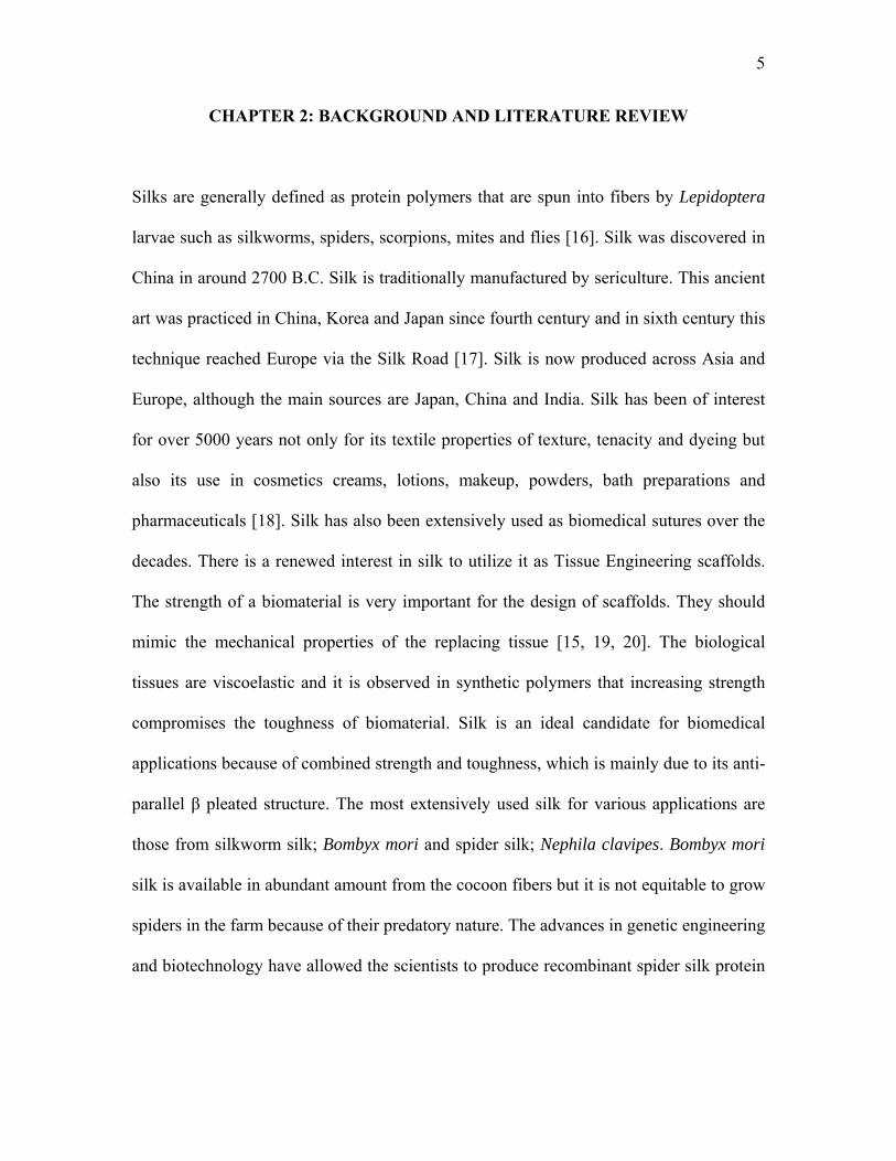
Silk fibers are 10-20 µm in diameter. Each fiber consists of core protein covered by a
coating protein (sericin) that glues core fibers together [21]. The fibers are not circular in
cross section but appear triangular as shown in Figure 1. The core protein consists of
three chains: heavy chain, light chain and a glycoprotein, P25 [22]. Heavy and light
chains are connected by disulphide bonds. Light chain is necessary for the secretion of
protein from the silk glands. P25 is connected to both heavy and light chains by non-
covalent interactions. P25 is necessary for the assembly of heavy and light chains [22].
Heavy chain is fiber forming protein and its structure determines properties of silk fiber.
Heavy chain is commonly referred as fibroin protein. Electrophoretic analyses of silk
cocoons have revealed presence of several minor proteins of unknown function. These
low molecular weight proteins are classified as non-structural silk proteins. [23].
Figure 1. Electron microscopic image showing cross section of Bombyx mori silk fiber.
7
2.1.2. Spider Silk
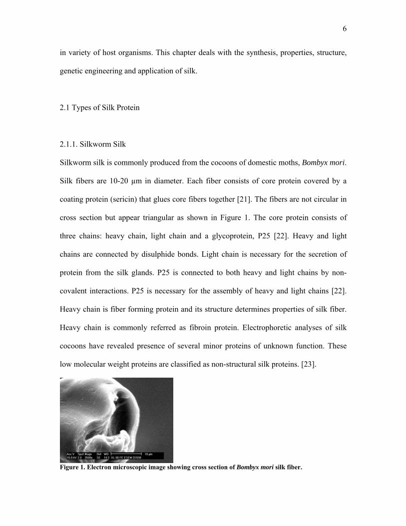
Nephila clavipes can produce seven types of silk from seven different silk glands as
shown in Figure 2 depending on needs and environmental conditions. Spiders use silk for
variety of functions including reproduction as cocoon capsular structures, lines for prey
capture, lifeline support (dragline), web construction and adhesion. Flaggifrom silk is
elastic in nature. The dragline silk is known for its combine strength and toughness.
Dragline silk from major ampullate glands of Nephila clavipes has crystalline regions of
anti-parallel β-sheet interspersed with elastic amorphous segments. These two segments
are represented by two different proteins, MaSp1 (Major Ampullate Spidroin 1) and
MaSp2 (Major Ampullate Spidroin 2) coded by different genes [24, 25]. The fibers are
much smaller (4 µm) than Bombyx mori and they are circular in cross section.
Figure 2. Different types of silk produced by spider Nephila clavipes.
8
2.2. Structure and Properties of Silk
2.2.1. Structure of Silk
The gene for the fibroin protein (H-fib gene) is located on 25th chromosome of Bombyx
mori silkworm and consists of two exons and one intron. The full sequence of the gene
was completed by shotgun sequencing strategy and physical map-based sequencing [26,
27]. Fibroin protein consists of 5263 residues having molecular weight of 391,367
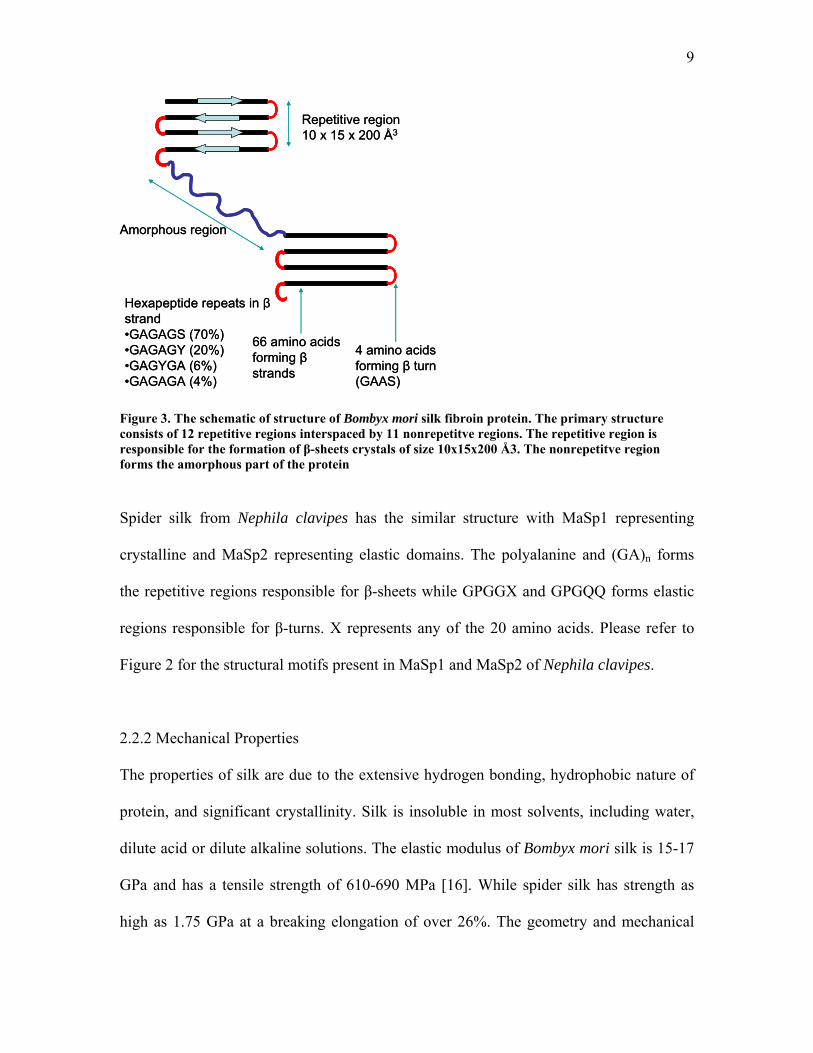
daltons. The primary structure of Bombyx mori silk consists of 12 repetitive regions
called crystalline regions and 11 non repetitive interspaced regions called amorphous
regions[27]. The composition of various amino acids in fibroin is 45.9% glycine, 30.3%
alanine, 12.1% serine, 5.3% tyrosine, 1.8% valine and 4.7% other remaining amino acids.
The crystalline regions make up 94% of the sequence and each repetitive region is an
average 413 residues in length. The majority of the repetitive region is made up of
hexapeptides repeats [27]. These are GAGAGS, GAGAGY, GAGAGA and GAGYGA.
The repeat GAGAGS is the most frequently (70%) occurring hexapeptide repeat
sequence. Please refer to the appendix A1 for the amino acids abbreviation used in this
thesis. The crystalline repetitive region is responsible for the secondary structure (anti-
parallel β pleated sheets) of the protein. Each crystal is on an average made up of 4
individual β strands each 11 amino acids long. The β strands are connected to one another
by β turn made up of GAAS amino acids. The amorphous regions consist of 42-43
residues and are linkers between repetitive domains. The primary sequence of heavy
chain also contains header (151-residue) and C Terminal (58-residue) sequences[27].
Figure 3 shows the structure of silk fibroin.
9
Amorphous region
66 amino acids forming βstrands
4 amino acids forming β turn (GAAS)
Repetitive region10 x 15 x 200 Å3
Hexapeptide repeats in βstrand •GAGAGS (70%)•GAGAGY (20%)•GAGYGA (6%)•GAGAGA (4%)
Amorphous region
66 amino acids forming βstrands
4 amino acids forming β turn (GAAS)
Repetitive region10 x 15 x 200 Å3
Hexapeptide repeats in βstrand •GAGAGS (70%)•GAGAGY (20%)•GAGYGA (6%)•GAGAGA (4%)
Figure 3. The schematic of structure of Bombyx mori silk fibroin protein. The primary structure consists of 12 repetitive regions interspaced by 11 nonrepetitve regions. The repetitive region is responsible for the formation of β-sheets crystals of size 10x15x200 Å3. The nonrepetitve region forms the amorphous part of the protein
Spider silk from Nephila clavipes has the similar structure with MaSp1 representing
crystalline and MaSp2 representing elastic domains. The polyalanine and (GA)n forms
the repetitive regions responsible for β-sheets while GPGGX and GPGQQ forms elastic
regions responsible for β-turns. X represents any of the 20 amino acids. Please refer to
Figure 2 for the structural motifs present in MaSp1 and MaSp2 of Nephila clavipes.
2.2.2 Mechanical Properties
The properties of silk are due to the extensive hydrogen bonding, hydrophobic nature of
protein, and significant crystallinity. Silk is insoluble in most solvents, including water,
dilute acid or dilute alkaline solutions. The elastic modulus of Bombyx mori silk is 15-17
GPa and has a tensile strength of 610-690 MPa [16]. While spider silk has strength as
high as 1.75 GPa at a breaking elongation of over 26%. The geometry and mechanical
10
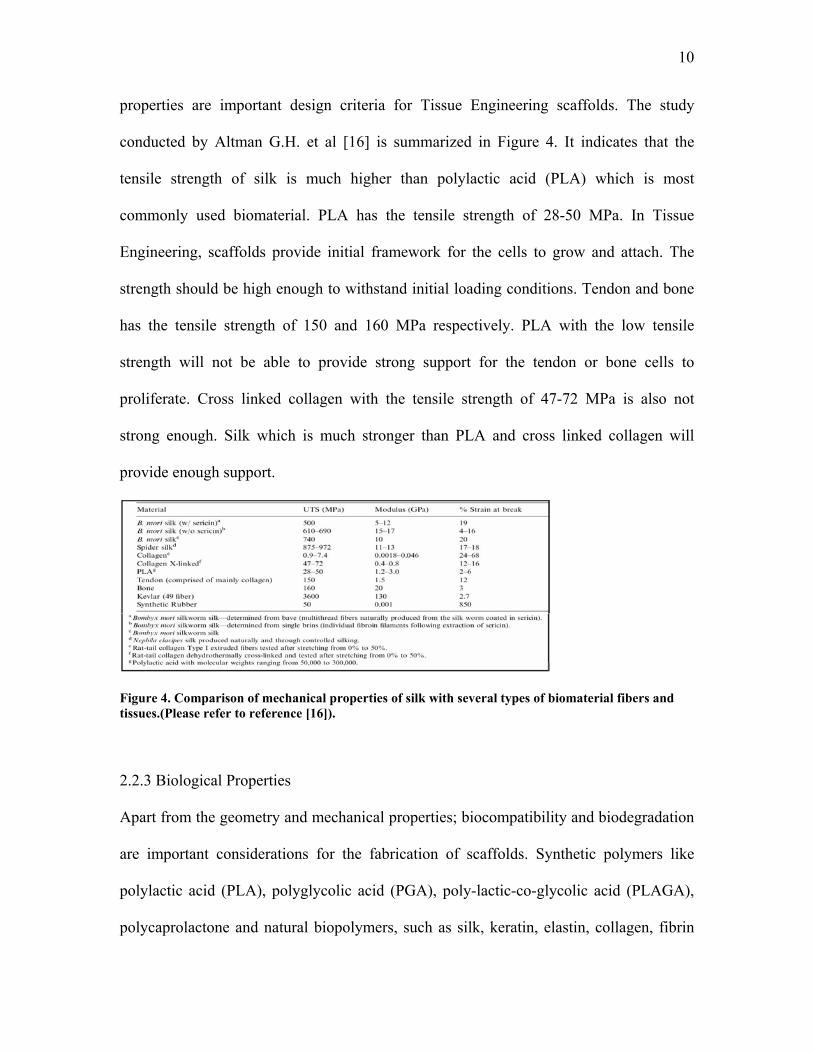
properties are important design criteria for Tissue Engineering scaffolds. The study
conducted by Altman G.H. et al [16] is summarized in Figure 4. It indicates that the
tensile strength of silk is much higher than polylactic acid (PLA) which is most
commonly used biomaterial. PLA has the tensile strength of 28-50 MPa. In Tissue
Engineering, scaffolds provide initial framework for the cells to grow and attach. The
strength should be high enough to withstand initial loading conditions. Tendon and bone
has the tensile strength of 150 and 160 MPa respectively. PLA with the low tensile
strength will not be able to provide strong support for the tendon or bone cells to
proliferate. Cross linked collagen with the tensile strength of 47-72 MPa is also not
strong enough. Silk which is much stronger than PLA and cross linked collagen will
provide enough support.
Figure 4. Comparison of mechanical properties of silk with several types of biomaterial fibers and tissues.(Please refer to reference [16]).
2.2.3 Biological Properties
Apart from the geometry and mechanical properties; biocompatibility and biodegradation
are important considerations for the fabrication of scaffolds. Synthetic polymers like
polylactic acid (PLA), polyglycolic acid (PGA), poly-lactic-co-glycolic acid (PLAGA),
polycaprolactone and natural biopolymers, such as silk, keratin, elastin, collagen, fibrin
11
clot ...etc. are extensively used because of their properties. The natural materials are of
considerable interest due to their structural properties and superior biocompatibility.
However there were several concerns regarding the biocompatibility of silk from Bombyx
mori. It was considered as an agent inducing Type I allergic response. Silk was known to
cause complications including asthma and specific up regulation of Immunoglobulin E
(IgE) levels [16]. Silk sutures were withdrawn from the market for this reason. But it was
observed that sericin was responsible for this sensitization [16, 21]. When sericin was
removed and replaced by wax or silicone coating in commercial sutures, the allergic
response was not observed. Thus virgin silk (fibroin containing sericin gum) is potential
allergen but degummed silk in which sericin is removed is biocompatible. Spider silk
from Nephila clavipes does not have sericin. In vitro evaluation of degummed fibroin
demonstrates that the interactions of fibroin with the humoral components of the
inflammatory system are comparable with those of polystyrene and poly (2-hydroxyethyl
methacrylate), the two materials used extensively for biomedical applications [28]. Silk is
susceptible to proteolytic degradation, usually mediated by a foreign body response in
vivo. In general, silk fibers lose the majority of their tensile strength within 1 year in vivo,
and fail to be recognized at the site within 2 years. Within blood, silk is thrombogenic.
However, the response is moderate and subsides with time [16].
12
2.3 Production of Silk Fibers
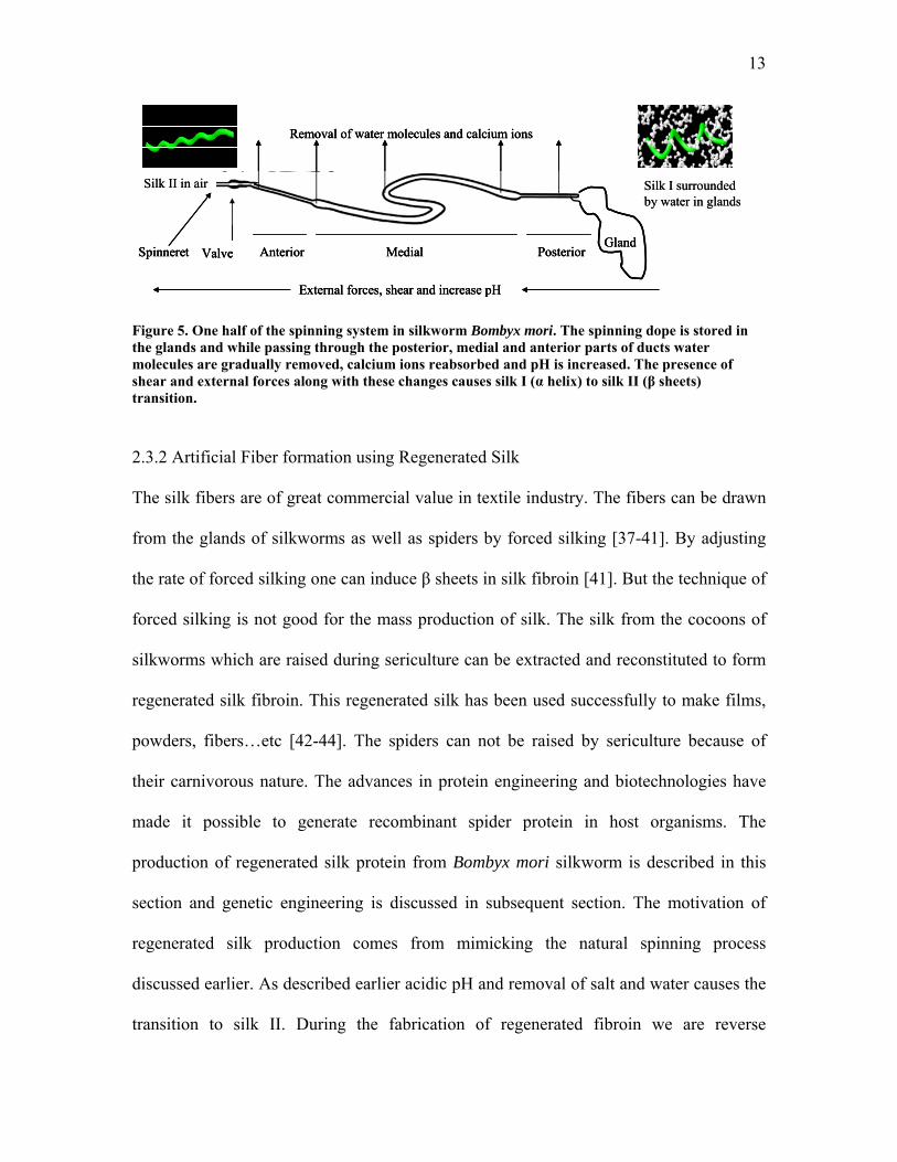
2.3.1 Natural Silk Spinning Process
The ease with which silkworms and spiders spin silk at ambient conditions has been a
topic of curiosity and research since existence [22, 29-36] but the factors controlling the
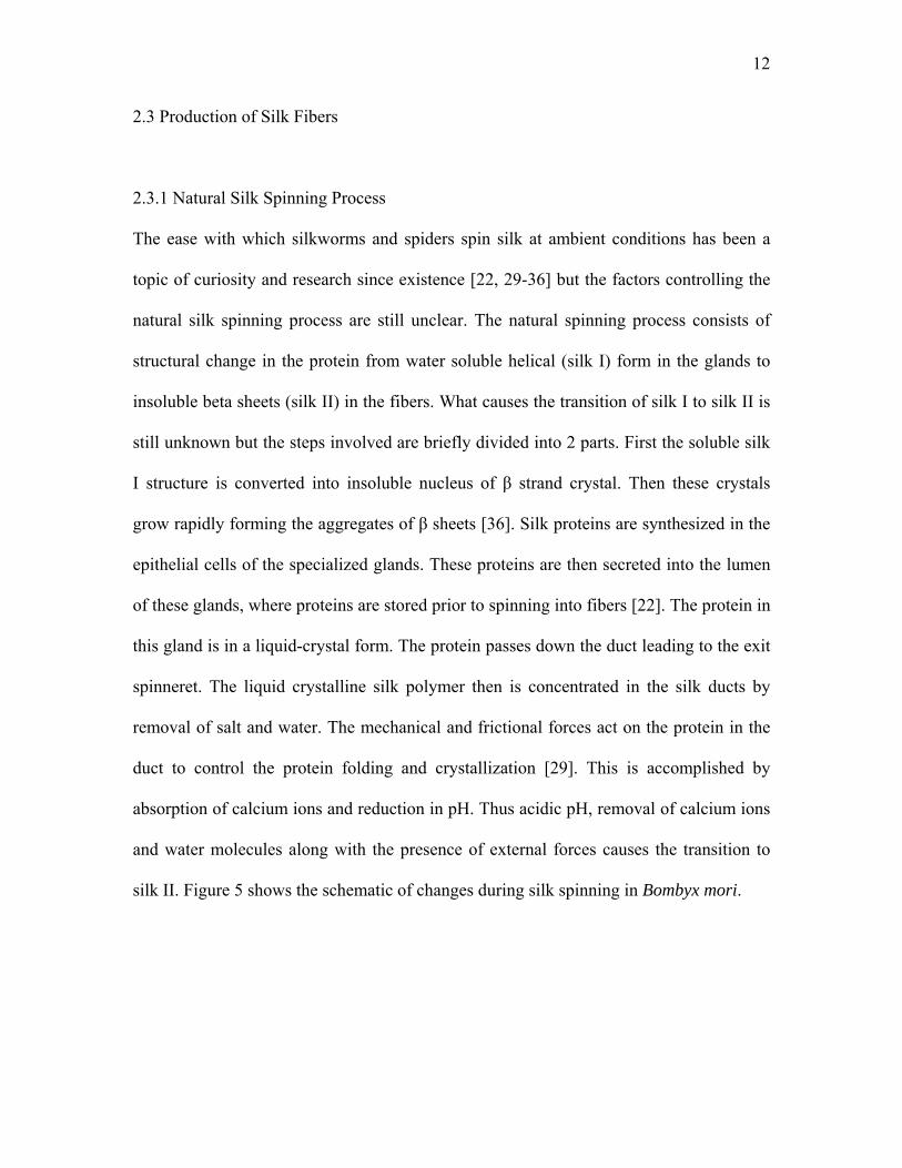
natural silk spinning process are still unclear. The natural spinning process consists of
structural change in the protein from water soluble helical (silk I) form in the glands to
insoluble beta sheets (silk II) in the fibers. What causes the transition of silk I to silk II is
still unknown but the steps involved are briefly divided into 2 parts. First the soluble silk
I structure is converted into insoluble nucleus of β strand crystal. Then these crystals
grow rapidly forming the aggregates of β sheets [36]. Silk proteins are synthesized in the
epithelial cells of the specialized glands. These proteins are then secreted into the lumen
of these glands, where proteins are stored prior to spinning into fibers [22]. The protein in
this gland is in a liquid-crystal form. The protein passes down the duct leading to the exit
spinneret. The liquid crystalline silk polymer then is concentrated in the silk ducts by
removal of salt and water. The mechanical and frictional forces act on the protein in the
duct to control the protein folding and crystallization [29]. This is accomplished by
absorption of calcium ions and reduction in pH. Thus acidic pH, removal of calcium ions
and water molecules along with the presence of external forces causes the transition to
silk II. Figure 5 shows the schematic of changes during silk spinning in Bombyx mori.
13
PosteriorMedialAnteriorValveSpinneretGland
Removal of water molecules and calcium ions
External forces, shear and increase pH
Silk I surrounded by water in glands
Silk II in air
PosteriorMedialAnteriorValveSpinneretGland
Removal of water molecules and calcium ions
External forces, shear and increase pH
PosteriorMedialAnteriorValveSpinneretGland
Removal of water molecules and calcium ions
External forces, shear and increase pH
Silk I surrounded by water in glands
Silk II in air
Figure 5. One half of the spinning system in silkworm Bombyx mori. The spinning dope is stored in the glands and while passing through the posterior, medial and anterior parts of ducts water molecules are gradually removed, calcium ions reabsorbed and pH is increased. The presence of shear and external forces along with these changes causes silk I (α helix) to silk II (β sheets) transition.
2.3.2 Artificial Fiber formation using Regenerated Silk
The silk fibers are of great commercial value in textile industry. The fibers can be drawn
from the glands of silkworms as well as spiders by forced silking [37-41]. By adjusting
the rate of forced silking one can induce β sheets in silk fibroin [41]. But the technique of
forced silking is not good for the mass production of silk. The silk from the cocoons of
silkworms which are raised during sericulture can be extracted and reconstituted to form
regenerated silk fibroin. This regenerated silk has been used successfully to make films,
powders, fibers…etc [42-44]. The spiders can not be raised by sericulture because of
their carnivorous nature. The advances in protein engineering and biotechnologies have
made it possible to generate recombinant spider protein in host organisms. The
production of regenerated silk protein from Bombyx mori silkworm is described in this
section and genetic engineering is discussed in subsequent section. The motivation of
regenerated silk production comes from mimicking the natural spinning process
discussed earlier. As described earlier acidic pH and removal of salt and water causes the
transition to silk II. During the fabrication of regenerated fibroin we are reverse
14
processing the natural spinning conditions to generate spinnable silk protein. Silk cocoon
fibers having silk II structure is first dissolved in concentrated salt solution. Then salt is
removed by dialysis against water. Finally water is removed by lyophilization or air-
drying or casting to from regenerated silk protein. The regenerated silk protein has a
heterogeneous structure mainly made up of random coils. This is slightly different than
the helical silk I structure found in the glands. The regenerated silk protein then can be
dissolved in an appropriate solvent and wet spun into a fiber or cast into a film. The films
or fibers fabricated from regenerated silk protein are treated with methanol which is a
known coagulant of silk protein [43]. It induces crystallization in silk fibroin by forming
β sheets. This gives us back the structure similar to silk II. The regenerated silk protein
does not have structure similar to natural silk. This affects the mechanical properties of
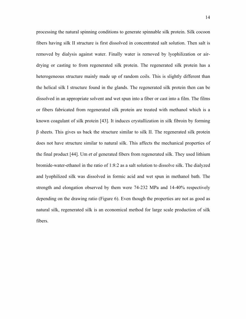
the final product [44]. Um et al generated fibers from regenerated silk. They used lithium
bromide-water-ethanol in the ratio of 1:8:2 as a salt solution to dissolve silk. The dialyzed
and lyophilized silk was dissolved in formic acid and wet spun in methanol bath. The
strength and elongation observed by them were 74-232 MPa and 14-40% respectively
depending on the drawing ratio (Figure 6). Even though the properties are not as good as
natural silk, regenerated silk is an economical method for large scale production of silk
fibers.
15
Figure 6. Mechanical properties of raw silk fiber compared to the regenerated silk.
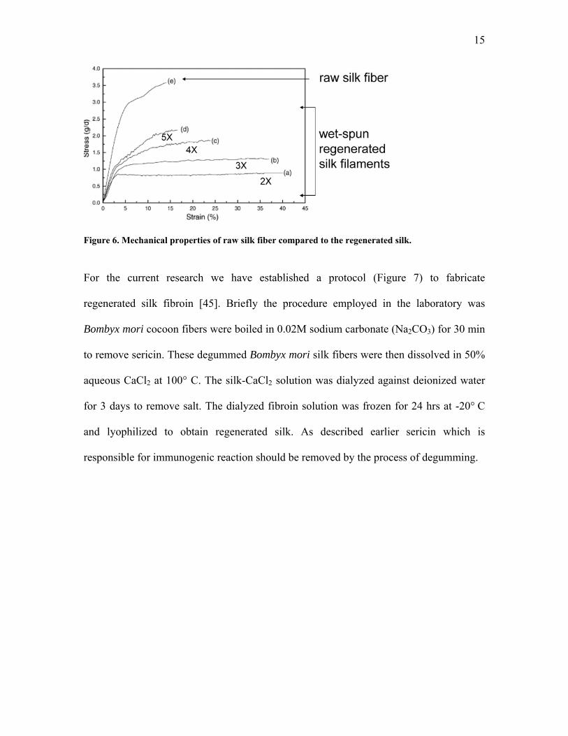
For the current research we have established a protocol (Figure 7) to fabricate
regenerated silk fibroin [45]. Briefly the procedure employed in the laboratory was
Bombyx mori cocoon fibers were boiled in 0.02M sodium carbonate (Na2CO3) for 30 min
to remove sericin. These degummed Bombyx mori silk fibers were then dissolved in 50%
aqueous CaCl2 at 100° C. The silk-CaCl2 solution was dialyzed against deionized water
for 3 days to remove salt. The dialyzed fibroin solution was frozen for 24 hrs at -20° C
and lyophilized to obtain regenerated silk. As described earlier sericin which is
responsible for immunogenic reaction should be removed by the process of degumming.
16
Figure 7. Schematic of the production of regenerated silk fibroin.
2.3.3 Electrospinning
It is well known that biological tissues consist of well organized hierarchical fibrous
structures [46] which are nano scale. The successful regeneration of biological tissue and
organs calls for the development of fibrous structures with fiber architectures conducive
to cell attachment and proliferation before they can differentiate into a tissue. Of
particular interest in Tissue Engineering is the creation of reproducible and biocompatible
3-dimensional scaffold for cell ingrowth resulting in bio-matrix composites for various
tissues repair and replacement. In the natural tissues the cells are embedded in the
extracellular matrix (ECM) mainly made up of collagen and elastin. The scaffolds for the
Tissue Engineering application should mimic the mechanical properties and hierarchical
organization of the ECM. The scaffolds replacing a tissue should be fibrous as well as
17
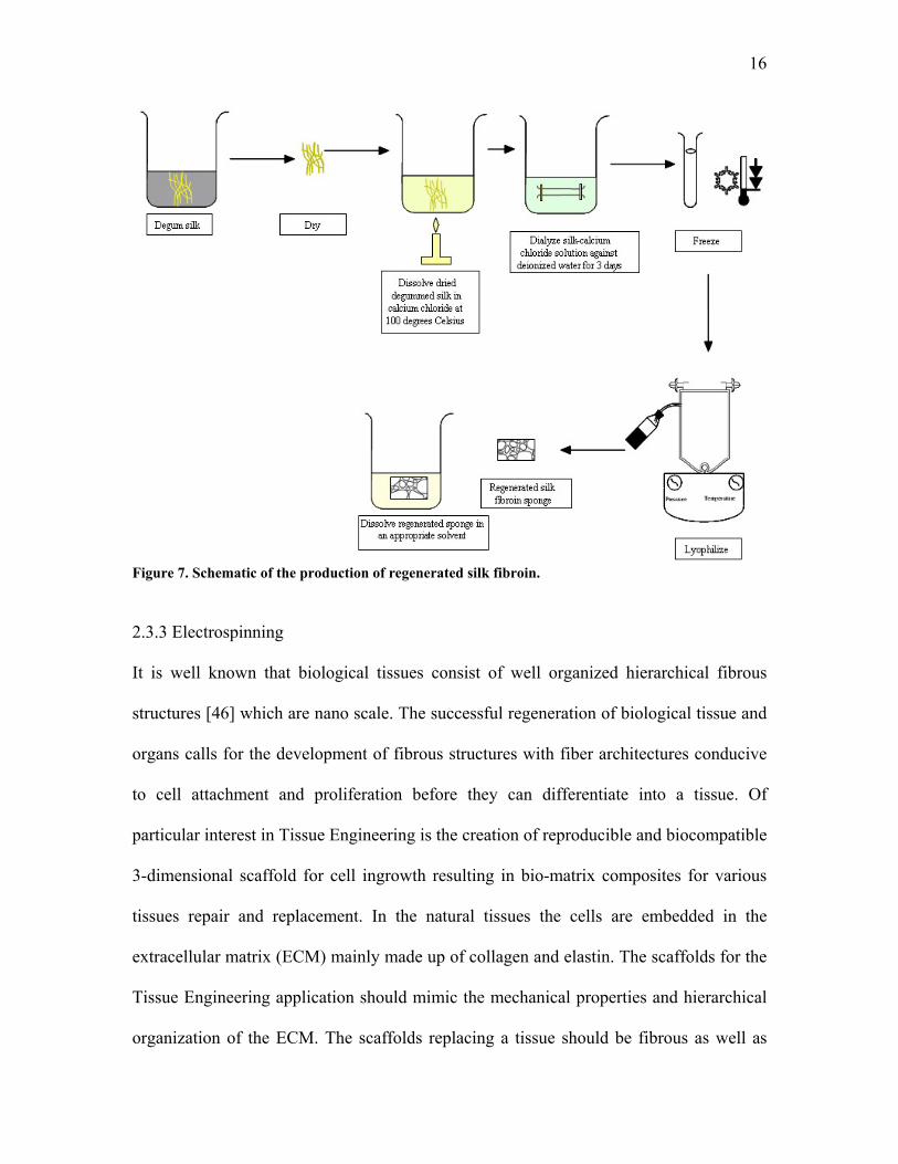
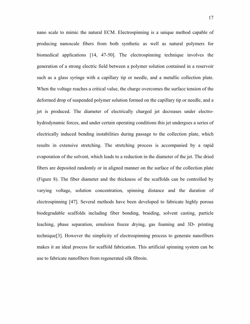
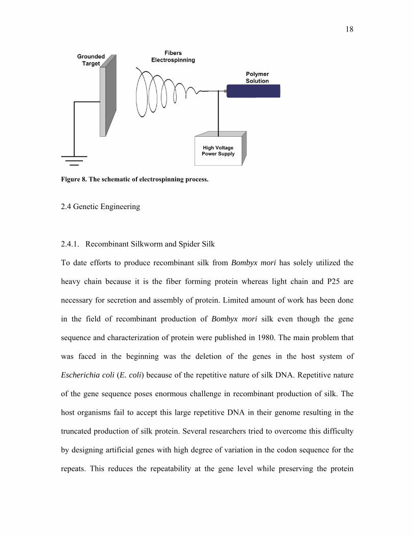
nano scale to mimic the natural ECM. Electrospinning is a unique method capable of
producing nanoscale fibers from both synthetic as well as natural polymers for
biomedical applications [14, 47-50]. The electrospinning technique involves the
generation of a strong electric field between a polymer solution contained in a reservoir
such as a glass syringe with a capillary tip or needle, and a metallic collection plate.
When the voltage reaches a critical value, the charge overcomes the surface tension of the
deformed drop of suspended polymer solution formed on the capillary tip or needle, and a
jet is produced. The diameter of electrically charged jet decreases under electro-
hydrodynamic forces, and under certain operating conditions this jet undergoes a series of
electrically induced bending instabilities during passage to the collection plate, which
results in extensive stretching. The stretching process is accompanied by a rapid
evaporation of the solvent, which leads to a reduction in the diameter of the jet. The dried
fibers are deposited randomly or in aligned manner on the surface of the collection plate
(Figure 8). The fiber diameter and the thickness of the scaffolds can be controlled by
varying voltage, solution concentration, spinning distance and the duration of
electrospinning [47]. Several methods have been developed to fabricate highly porous
biodegradable scaffolds including fiber bonding, braiding, solvent casting, particle
leaching, phase separation, emulsion freeze drying, gas foaming and 3D- printing
technique[3]. However the simplicity of electrospinning process to generate nanofibers
makes it an ideal process for scaffold fabrication. This artificial spinning system can be
use to fabricate nanofibers from regenerated silk fibroin.
18
Figure 8. The schematic of electrospinning process.
2.4 Genetic Engineering
2.4.1. Recombinant Silkworm and Spider Silk
To date efforts to produce recombinant silk from Bombyx mori has solely utilized the
heavy chain because it is the fiber forming protein whereas light chain and P25 are
necessary for secretion and assembly of protein. Limited amount of work has been done
in the field of recombinant production of Bombyx mori silk even though the gene
sequence and characterization of protein were published in 1980. The main problem that
was faced in the beginning was the deletion of the genes in the host system of
Escherichia coli (E. coli) because of the repetitive nature of silk DNA. Repetitive nature
of the gene sequence poses enormous challenge in recombinant production of silk. The
host organisms fail to accept this large repetitive DNA in their genome resulting in the
truncated production of silk protein. Several researchers tried to overcome this difficulty
by designing artificial genes with high degree of variation in the codon sequence for the
repeats. This reduces the repeatability at the gene level while preserving the protein
19
sequence. Unfortunately this was met with the limited success [51]. The cloning of the
fibroin gene in E. coli was first reported by Ohshima and Suzuki [52]. The whole or a
part of DNA extracted from the posterior silk glands of Bombyx mori (16 kilobases long)
was cloned into bacterial expression system. They obtained 13 E. coli clones by ligation
of plasmid expressed in E. coli. But the expression of the protein showed deletions in
repetitive region because of ribosome termination errors thus resulting into truncated
synthesis of silk protein. This kind of truncated synthesis was observed in yeast Pichia
pastoris (P. pastoris) as well [51].
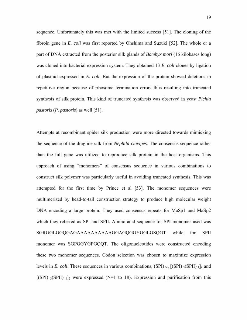
Attempts at recombinant spider silk production were more directed towards mimicking
the sequence of the dragline silk from Nephila clavipes. The consensus sequence rather
than the full gene was utilized to reproduce silk protein in the host organisms. This
approach of using “monomers” of consensus sequence in various combinations to
construct silk polymer was particularly useful in avoiding truncated synthesis. This was
attempted for the first time by Prince et al [53]. The monomer sequences were
multimerized by head-to-tail construction strategy to produce high molecular weight
DNA encoding a large protein. They used consensus repeats for MaSp1 and MaSp2
which they referred as SPI and SPII. Amino acid sequence for SPI monomer used was
SGRGGLGGQGAGAAAAAAAAAAGGAGQGGYGGLGSQGT while for SPII
monomer was SGPGGYGPGQQT. The oligonucleotides were constructed encoding
these two monomer sequences. Codon selection was chosen to maximize expression
levels in E. coli. These sequences in various combinations, (SPI) N, [(SPI) 3(SPII) 1]4 and
[(SPI) 5(SPII) 1]2 were expressed (N=1 to 18). Expression and purification from this
20
system yielded 15-2 mg/l of spider silk protein. Circular dichroism measurements
indicated that these synthetic spider silks have substantial β -sheet structure. Later, Lewis
et al constructed 84 and 59 base oligonucleotides encoding the amino acid consensus
repeats from the major ampullate spider silk protein and expressed in E. coli using similar
strategy [24]. Fahnestock et al expressed the dragline silk analog proteins in the
expression systems of E. coli as well as P. pastoris [54, 55]. Lazaris et al investigated the
expression of recombinant spider silk proteins in mammalian cells using spider dragline
silk partial cDNAs [56]. Two cell lines, bovine mammary epithelial alveolar cells and
baby hamster kidney cells were used to express the protein. They went further and
demonstrated the wet spinning of spider silk monofilaments. Although the mechanical
properties were not similar to the native spider silk but this was the first study
demonstrating the production and spinning of recombinant spider silk. For the large scale
manufacturing of silk protein transgenic animal and plants are also been tried [57, 58].
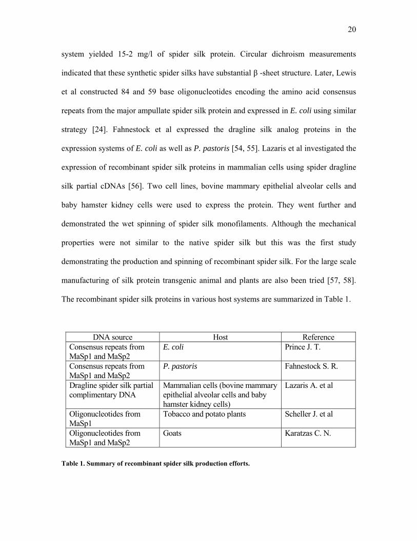
The recombinant spider silk proteins in various host systems are summarized in Table 1.
DNA source Host Reference Consensus repeats from MaSp1 and MaSp2
E. coli Prince J. T.
Consensus repeats from MaSp1 and MaSp2
P. pastoris Fahnestock S. R.
Dragline spider silk partial complimentary DNA
Mammalian cells (bovine mammary epithelial alveolar cells and baby hamster kidney cells)
Lazaris A. et al
Oligonucleotides from MaSp1
Tobacco and potato plants Scheller J. et al
Oligonucleotides from MaSp1 and MaSp2
Goats Karatzas C. N.
Table 1. Summary of recombinant spider silk production efforts.
21
2.4.2 Hybrid Silk
It is apparent from the discussion so far that the truncated synthesis has been the limiting
factor in expressing silks where the repetitive nature of the silk gene makes its expression
in the host organisms, particularly E. coli and P. pastoris difficult. But this property of
the fibrous protein was used as an advantage by many. The repeats from the silk protein
can be expressed as a monomer and can be multimerized to form a polymer with high
molecular weight. This protein obviously will not be same as silk but it is hoped it will
retain most of the structural and mechanical properties of native silk. The repeats from
the silk can be combined with the repeats from other fibrous protein like elastin or
collagen to create novel protein polymers with unique properties [59-62]. Collagen and
elastin are the main components of natural ECM of the tissues so these hybrid proteins
are good candidates for fabrication of scaffolds for Tissue Engineering and drug delivery.
Megeed Z. et al synthesized the high molecular silk-like protein polymers using the
GAGAGS repeat from Bombyx mori and incorporated repetitive motif GVGVP from
elastin to construct the protein having combined property from silk as well as elastin [63].
The silk repeats were used for their mechanical property of combined strength and
toughness. The elastin repeats were used for gaining more control over the
biodegradability. They also incorporated various cell attachment domains to increase the
biocompatibility of these “hybrid” proteins. They also constructed a collagen-like protein
using the repetitive motif from type I collagen found commonly in skin, bones, tendons,
cartilage, blood vessels and teeth. This pioneering work towards the production of hybrid
silk with tailor-made properties has been duplicated by many scientists [59, 62]. Artificial
protein polymers produced by Megeed Z. et al. are summarized in Table 2. It is important
22
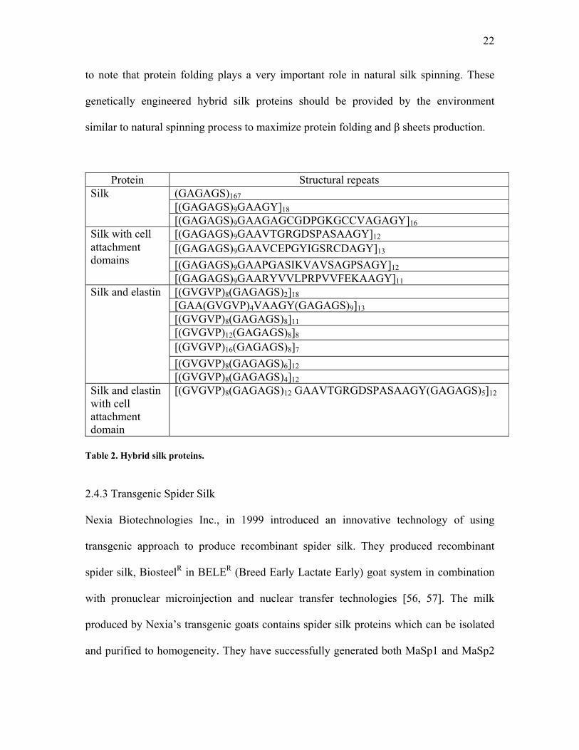
to note that protein folding plays a very important role in natural silk spinning. These
genetically engineered hybrid silk proteins should be provided by the environment
similar to natural spinning process to maximize protein folding and β sheets production.
Protein Structural repeats (GAGAGS)167 [(GAGAGS)9GAAGY]18
Silk
[(GAGAGS)9GAAGAGCGDPGKGCCVAGAGY]16 [(GAGAGS)9GAAVTGRGDSPASAAGY]12 [(GAGAGS)9GAAVCEPGYIGSRCDAGY]13 [(GAGAGS)9GAAPGASIKVAVSAGPSAGY]12
Silk with cell attachment domains
[(GAGAGS)9GAARYVVLPRPVVFEKAAGY]11 [(GVGVP)8(GAGAGS)2]18 [GAA(GVGVP)4VAAGY(GAGAGS)9]13 [(GVGVP)8(GAGAGS)8]11 [(GVGVP)12(GAGAGS)8]8 [(GVGVP)16(GAGAGS)8]7 [(GVGVP)8(GAGAGS)6]12
Silk and elastin
[(GVGVP)8(GAGAGS)4]12 Silk and elastin with cell attachment domain
[(GVGVP)8(GAGAGS)12 GAAVTGRGDSPASAAGY(GAGAGS)5]12
Table 2. Hybrid silk proteins.
2.4.3 Transgenic Spider Silk
Nexia Biotechnologies Inc., in 1999 introduced an innovative technology of using
transgenic approach to produce recombinant spider silk. They produced recombinant
spider silk, BiosteelR in BELER (Breed Early Lactate Early) goat system in combination
with pronuclear microinjection and nuclear transfer technologies [56, 57]. The milk
produced by Nexia’s transgenic goats contains spider silk proteins which can be isolated
and purified to homogeneity. They have successfully generated both MaSp1 and MaSp2
23
in their goat system. Scheller et al generated transgenic tobacco and potato plants that
express recombinant Nephila clavipes dragline silk proteins [58]. Synthetic spider silk
genes were cloned into an expression vector in transgenic plants under the control of the
cauliflower mosaic virus promoter. The proteins were retained in the endoplasmic
reticulum of leaves of tobacco and potato and potato tubers. The ethical issues concerning
the use of animals and plants for this purpose need to be addressed. But the research has
proved that animals and variety of crop plants could serve as inexpensive bioreactors for
the large-scale production of spider silk proteins.
2.5 Biomedical Applications of Silk
2.5.1 Tissue Engineering
Tissue engineering works on the principle of replacement of dead or diseased tissue with
living tissues. This restores the structure and function of the native tissue. Much of the
work in tissue engineering to date has been focused on using a biocompatible scaffold
(degradable or non-degradable) since it offers the ability to form and shape tissues in
vitro relatively rapidly and with the properties representative of host tissues. Silk, which
has been used as suture material provides the basic mechanical properties and unique
features like high strength, resistance to compressive forces, and flexibility for building
such scaffolds. It can be manipulated easily into different shapes so it is been studied as a
material for tissue engineering scaffolds. Altman G.H. et al [64] designed silk fiber
matrix for anterior cruciate ligaments (ACL). To mimic the mechanical and geometrical
properties of ACL, silk fiber wire rope for multi-fiber matrix was designed that reduces
24
the high linear stiffness associated with single fiber. The ultimate tensile stress, stiffness,
yielding point and elongation of silk multi-fiber scaffolds were found to be similar to
natural ACL. This protein matrix supported the attachment, expansion and differentiation
of adult human progenitor bone marrow stromal cells based on findings from scanning
electron microscopy, cell proliferation assay by DNA quantitation and the expression of
collagen types I and III and tenascin-C markers. Sofia S. et al [65] used functionalized
silk-based biomaterial for bone formation. They used silk films which were covalently
bonded to integrin recognizing RGD sequence and parathyroid hormone known for its
osteoinductive (bone formation) properties. The results suggested significant increase in
osteoblasts cells attached to these films compared to plastic. Thus, unique mechanical
properties of the silk provide numerous opportunities for fabrication of biomaterial
scaffolds constructed from these proteins and their variants.
2.5.2 Drug Delivery
Drug delivery is a rapidly developing field in biomedical research. It is interdisciplinary
and requires expertise in biotechnology, pharmacology, microbiology, biochemistry,
polymer chemistry and materials engineering. Controlled drug delivery has attracted the
attention of many researchers as it allows the site specific release of the drug with
precision. This eliminates adverse effects like over dosage and toxicity of the drug.
Environmentally responsive systems release drug in response to stimuli like temperature,
pH or enzymes. Advantages of using such systems include maintenance of drug levels
within desired range, fewer administrations, optimal use of the drug, and better patient
compliance. Biocompatible and biodegradable polymers are used as carriers for delivery
25
of drugs or active agents. The material used for drug delivery should be biocompatible,
chemically inert, easily processable and physically and mechanically stable. Biopolymers
are of great interest for this kind of application. Silk and silk-like variants are used by
some scientists as carriers for drug delivery. Their biocompatibility and ability to form
hydrogels in situ makes them attractive candidates for the localized, controlled delivery
of therapeutic agents. Their ability to incorporate drugs at room temperature, by simple
mixing, and without the use of toxic or denaturing solvents makes them attractive for the
delivery of protein or DNA-based therapies. Megeed et al [63, 66] created a novel silk-
elastin like protein polymer for controlled drug delivery. They suggested that silk repeats
(GAGAGS) and elastin repeats (GVGVP) in various combinations can produce protein
polymers of different molecular weights. It is easy to control gel-formation, stimuli-
sensitivity, biodegradation, and biorecognition of these genetically synthesized
biopolymers. They demonstrated the release of recombinant protein mitotoxin (Pantarin)
as well as DNA (genes) using these matrices.
2.6. Bone Tissue Engineering
2.6.1 Structure and Functions of Bone
Bone is one of the hardest tissues of the body. It is tough and has considerable elasticity.
It is made up of 2 types of tissue, an external, compact tissue and internal cancellous
tissue. The main difference between two is the amount of solid matter in them. Compact
tissue is made up of large cavities with abundant solid matter, while cancellous tissue has
26
larges spaces and the solid matter is in smaller quantity. Bone is covered by a layer of
fibrous tissue called periosteum which is in turn made up of an outer connective tissue
and inner elastic layer. The blood vessels, nerves and lymphatic vessels enter bone
through periosteum. The interior of bone is filled with marrow, areolar connective tissue
and blood vessels. Depending on the location bone marrow is either yellow or red in
color. The yellow marrow is mainly made up of fat cells whereas red marrow consists of
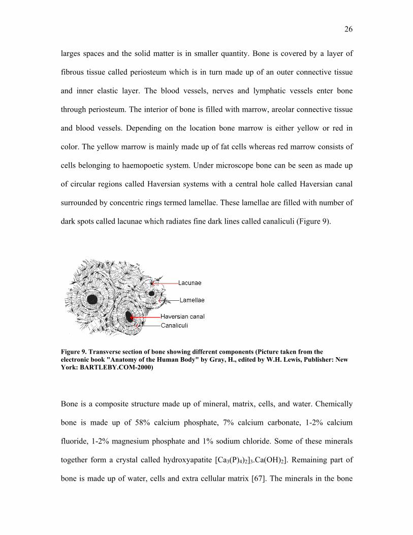
cells belonging to haemopoetic system. Under microscope bone can be seen as made up
of circular regions called Haversian systems with a central hole called Haversian canal
surrounded by concentric rings termed lamellae. These lamellae are filled with number of
dark spots called lacunae which radiates fine dark lines called canaliculi (Figure 9).
Figure 9. Transverse section of bone showing different components (Picture taken from the electronic book "Anatomy of the Human Body" by Gray, H., edited by W.H. Lewis, Publisher: New York: BARTLEBY.COM-2000)
Bone is a composite structure made up of mineral, matrix, cells, and water. Chemically
bone is made up of 58% calcium phosphate, 7% calcium carbonate, 1-2% calcium
fluoride, 1-2% magnesium phosphate and 1% sodium chloride. Some of these minerals
together form a crystal called hydroxyapatite [Ca3(P)4)2]3.Ca(OH)2]. Remaining part of
bone is made up of water, cells and extra cellular matrix [67]. The minerals in the bone
27
are responsible for hardness and rigidity while the biological components like cells and
matrix are responsible for its tenacity. Bone cells are present in the lacunae. Bone has 3
main types of cells, osteoblasts, osteocytes and osteoclasts. Osteoblasts are bone forming
cells and are derived from mesenchymal stem cells [68]. They synthesize bone matrix.
Osteocytes are matured osteoblasts surrounded by bone matrix. They provide nutrition to
bone. Osteoclasts are multi nucleated giant cells derived from macrophage and they help
in bone resorption and remodeling. Collagen, primarily Type I collagen forms 90% of the
bone matrix. Collagen forms a fibrous network providing structural support to the cells.
Non-collagenous matrix proteins like proteoglycans and glycoproteins make up
remaining 10% of bone matrix. The functions of the bone includes mineral and ion
homeostasis, protection to internal organs and source of calcium, magnesium and
phosphate ions [68].
2.6.2. Bone Tissue Engineering Methods
Approximately 863,200 bone grafting procedures are performed each year in United
States alone [1] due to variety of reasons including fractures, deformities, problems with
corresponding joints and to alleviate pain [69]. Because of the problems like graft
rejection, donor site morbidity and disease transmission, Tissue Engineering of bone is
increasingly becoming the treatment of choice among surgeons. Cells, scaffolds and
factors are 3 basic components for any kind of Tissue Engineering. The materials used
for fabrication of scaffolds should be osteoconductive (favorable for the growth of cells)
and the signals should be osteoinductive (encourage bone differentiation). There is a
growing interest in using stem cells for bone Tissue Engineering. Stem cells have ability
28
to self replicate for longer period and can maintain their differentiation throughout the
life [70]. One such cell type is bone marrow stromal cells (BMSC). They are multi potent
in nature. They can differentiate into osteoblasts, chondrocytes, myocytes, neuronal cells,
and adipocytes if provided with the right signals [71]. They can be easily isolated from
the patient’s or donor’s bone marrow and cultured in vitro for the larger expansion. The
growth factors like fibroblast growth factor 2 (FGF-2) and dexamethasone are known to
induce osteogenic differentiation in BMSC [71, 72]. Osteoblasts which are normally
present in the bones are another type of cells extensively researched on for bone Tissue
Engineering. The cells from the periosteum of the bone can be used as well. The
periosteal cells are known to be osteogenic in the presence of high oxygen tension [73].
Apart from using the right kind of cells bioactive growth factors that induce osteogenesis
are important as well. The growth factors known for their osteogenic potential are FGF-2,
Bone morphogenic protein (BMP-2 &7), transforming growth factor-β 3 (TGF-β 3),
platelet derived growth factor (PDGF), insulin like growth factor (IGF), epidermal
growth factor (EGF), vascular endothelial growth factor (VEGF), dexamethasone,
ascorbic acid…etc [69, 70, 72, 74, 75]. The scaffolds material and design criteria to
fabricate a scaffold are another important and rapidly expanding field or research in bone
engineering [76]. Various absorbable or non absorbable ceramics, polymers and
composite materials are been used for the fabrication of scaffolds. There is renewed
interest in using natural protein based materials because of their superior
biocompatibility. Demineralized bone matrix, silk, collagen, fibrin, calcium phosphate,
PLA, PLAGA, polyethylene glycol, polyanhydrides, hydroxyapatite, dental plaster, and
titanium are some of the materials studied by various researchers for this purpose [4, 5,
29
10, 77-86]. The geometry of scaffolds is also important. Nanofibers, sintered
microspheres, foams are some examples.
It is apparent from this chapter that modern interest in silk is growing rapidly because of
their unique mechanical properties of combined strength and toughness. Silkworm silk
can be converted into regenerated silk which in turn can be used to make fibers, films,
powders…etc. Genetic engineering has opened new doors for scientists to construct
spider silk in transgenic plants and animal. Regenerated silkworm silk and transgenic
spider silk from Nexia Biotechnologies were used in the present study to fabricate
nanofibrous scaffolds for bone Tissue Engineering application. The research design and
objectives of this thesis is discussed in next chapter.
30
CHAPTER 3: RESEARCH DESIGN AND OBJECTIVES
Bombyx mori and Nephila clavipes are the most extensively used silk proteins for
biomedical applications. Bombyx mori silk is available in abundant amount from the
cocoon fibers of silkworm raised by sericulture but spiders are carnivorous in nature so it
is not equitable to grow them in farms. The advances in protein engineering and
biotechnologies have made it possible to generate recombinant spider protein in host
organisms. Nexia Biotechnologies Inc. has produced recombinant MaSp1 and MaSp2 silk
proteins from Nephila clavipes by transgenic technique. We have utilized the process of
electrospinning to fabricate nanofibrous scaffolds from natural silkworm cocoon fibers
and transgenic spider silk. The first step in electrospinning is to prepare a spinning dope
by dissolving silk protein in an appropriate solvent. Transgenic spider silk, MaSp1 and
MaSp2 from Nephila clavipes are in powder form and it can be dissolved easily in a
solvent. Bombyx mori silk which is in a fiber form is insoluble in most solvents. By
mimicking the natural spinning process a protocol has been established to make a
spinnable dope from Bombyx mori cocoon fibers. Unfortunately bio-mimicking the
process is not enough. The regenerated silk protein has lower mechanical properties than
raw silk fibers. The main focus of this thesis is to narrow this gap. It is necessary to learn
the changes happening in a structure of Bombyx mori protein during the process of
natural spinning and electrospinning dope preparation. This was carried out by molecular
dynamics simulations. Various methods including post spinning treatment with methanol
and stretching, incorporation of CNT and collagen were employed to improve the
properties and biocompatibility of scaffolds. The scaffolds were characterized for their
31
mechanical, electrical and structural properties. Cell-scaffolds interaction study was
carried out using bovine osteoblasts cells. Individual components of transgenic spider silk
Nephila clavipes, MaSp1 and MaSp2 were also electrospun to fabricate nanofibers.
MaSp1 was reinforced with CNT and these scaffolds were characterized and studied for
cell-scaffolds interaction as well.
The research objectives for this thesis are…
3.1 Structural Changes in Natural and Regenerated Silk
During the fabrication of regenerated fibroin we are reverse processing the natural
spinning conditions to generate spinnable silk protein. We studied the structural changes
in natural and regenerated silk protein by molecular dynamics simulation. It is known that
10 mg of calcium ions per gm of fibroin and pH of 5.2 is optimum for silk I to silk II
transition [87]. We calculated the compressive and tensile forces required for the
transition. The simulation studying the changes in silk structure at various stages of
fabrication of regenerated silk fibroin which involves dissolution in CaCl2, dialysis and
lyophilization was carried out as well. The simulation results were verified
experimentally by Raman Spectroscopy, Fourier Transform Infrared Spectroscopy (FT-
IR) and X-ray diffraction (XRD) studies.
3.2. Nanofibrous Scaffolds from Silkworm Silk
An investigation into the feasibility of producing nanofibers from regenerated Bombyx
mori silk fibers using the electrospinning process was carried. The processing parameters
32
like voltage, solution concentration, spinning distance and the duration of electrospinning
were optimized to generated continuous nanoscale fibers. The structural and physical
properties of the scaffolds were characterized by Environmental Scanning Electron
Microscopy (ESEM), Raman Spectroscopy, FT-IR and XRD studies. The mechanical
properties of were measured by Kawabata microtensile tester.
3.3. Modification of Mechanical Properties of Silkworm Silk Nanofibers
Various methods were utilized to change the mechanical properties of the electrospun
nanofibers. The methods employed were post-spinning treatments, co-electrospinning
regenerated silkworm silk with CNT, collagen and PLAGA. The structural, physical and
mechanical properties were evaluated and compared with the non-modified silkworm
nanofibers.
3.3.1. Post Spinning Modifications
Methanol acts as a coagulant for silk. It induces crystallization in silk fibroin by forming
β sheets [33, 43]. We tested the effect of methanol on regenerated silk nanofibers. It is
well known in Textile fibers that physical annealing helps aligning the polymer crystals
in the direction of stretching. We stretched the silk nanofibers to align β sheets in the
direction of pull. Electrospinning normally produce random mat of nanofibers. We
developed the procedure wherein one can fabricate aligned nanofibers. The post spinning
modifications were applied to both random and aligned nanofibers. The mechanical
properties of modified nanofibers were measured using Kawabata microtensile tester.
33
3.3.2. Co-electrospinning with Carbon Nanotubes
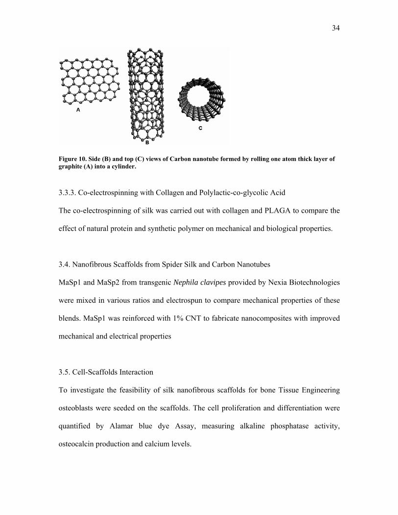
Since the discovery of Carbon Nanotubes (CNTs) by Ijima they have become intensely
studied material as the fillers for light weight and high strength composites[88, 89]. The
CNTs are one atom thick layer of graphite rolled into a cylinder (Figure 10). They are 1
nm in diameter and several microns in length. They are light weight, flexible and with
elastic modulus of 1 TPa, tensile strength of 37 GPa and breaking elongation of 6-30 %
are the hitherto the toughest material known [90-92]. The elongation balance theory in
textile engineering [93] and composite analysis [94] suggest that combining materials
with compatible elongation at break provide the most effective means of transferring
tensile properties. On the basis of this theory silk (15-20% elongation at break) and CNT
(6-30% elongation at break) are the most compatible material systems amongst the strong
industrial fibers known so far. It has been demonstrated by Ko et al. that co-
electrospinning provides an excellent method for aligning CNT in polymer fibril matrix
[89]. In another study [95], Atomic Force Microscope (AFM) in a taping mode was used
to determine the mechanical properties of nanocomposites prepared by co-
electrospinning 1 to 5 % by weight CNT in a polyacrylonitrile (PAN) matrix. A 4 to 5
fold increase in the properties was found with introduction of less than 1.5% by weight of
CNT to the PAN matrix. In this thesis we have co-electrospun CNT and silk protein to
fabricate novel nanocomposite scaffolds having improved mechanical and electrical
properties. Because of remarkable properties of CNTs only small amount is needed to
reinforce nanofibers. We have used 1% concentration by weight. For uniform dispersion
of CNTs and preventing agglomeration CNTs were sonicated and mixed with regenerated
silk protein to prepare a spinning dope.
34
Figure 10. Side (B) and top (C) views of Carbon nanotube formed by rolling one atom thick layer of graphite (A) into a cylinder.
3.3.3. Co-electrospinning with Collagen and Polylactic-co-glycolic Acid
The co-electrospinning of silk was carried out with collagen and PLAGA to compare the
effect of natural protein and synthetic polymer on mechanical and biological properties.
3.4. Nanofibrous Scaffolds from Spider Silk and Carbon Nanotubes
MaSp1 and MaSp2 from transgenic Nephila clavipes provided by Nexia Biotechnologies
were mixed in various ratios and electrospun to compare mechanical properties of these
blends. MaSp1 was reinforced with 1% CNT to fabricate nanocomposites with improved
mechanical and electrical properties
3.5. Cell-Scaffolds Interaction
To investigate the feasibility of silk nanofibrous scaffolds for bone Tissue Engineering
osteoblasts were seeded on the scaffolds. The cell proliferation and differentiation were
quantified by Alamar blue dye Assay, measuring alkaline phosphatase activity,
osteocalcin production and calcium levels.
35
CHAPTER 4: STRUCTURAL CHANGES IN NATURAL AND REGENERATED
SILK
4.1. Introduction
There is a growing interest in silk protein not only because of its textile applications but
also as a biomaterial. Silk is an ideal candidate for biomedical applications because of
combined strength and toughness, which is mainly due to its anti-parallel β pleated
structure. There is a renewed interest in silk to utilize it as Tissue Engineering scaffolds.
The natural silk spinning process in Bombyx mori silkworms consists of structural change
in the protein from water soluble helical (silk I) form in the glands to insoluble beta
sheets (silk II) in the fibers [33]. Many factors are involved in the transition of silk I to
silk II. Acidic pH, removal of calcium ions and water molecules from the ducts along
with the presence of external forces cause this transition [22, 29, 36]. However, the most
important one is the external forces acting on the protein while it is getting transported
from glands to ducts to spinneret during spinning process. The silk fibers are of great
commercial value. It is important to know the structural changes happening in the silk
protein during its spinning so that an artificial spinning system can be developed to
mimic these conditions. Efforts are made in converting natural cocoon silk fibers to
regenerated silk protein so that it can be transformed to meaningful geometries like films,
powders, fibers…etc [42-44] for Tissue Engineering applications. During the fabrication
of regenerated fibroin we are reverse processing the natural spinning conditions to
generate spinnable silk protein. Silk cocoon fibers having silk II structure is first
36
dissolved in concentrated salt solution. Then salt is removed by dialysis against water.
Finally water is removed by lyophilization or air-drying or casting to from regenerated
silk protein.
We have developed a protocol to fabricate regenerated silk protein which can be used to
prepare a spinning dope for electrospinning process. Electrospinning is a unique method
capable of producing nanoscale fibers from both synthetic as well as natural polymers for
biomedical applications [14, 47-50]. The nanofibers from regenerated silk protein can be
utilized for fabrication of Tissue Engineering scaffolds. The procedure employed in our
laboratory includes boiling Bombyx mori cocoon fibers in 0.02M sodium carbonate
(Na2CO3) for 30 min to remove sericin. These degummed Bombyx mori silk fibers are
then dissolved in 50% aqueous CaCl2 at 100° C. The silk-CaCl2 solution is then dialyzed
against deionized water for 3 days to remove salt. The dialyzed fibroin solution is frozen
for 24 hrs at -20° C and lyophilized to obtain regenerated silk. Sericin which is
responsible for immunogenic reaction should be removed by the process of degumming.
Regenerated silk is then dissolved in formic acid for electrospinning to generate
nanofibers [45, 96, 97]. The nanofibers are then treated with methanol which is known to
induce formation of β sheets [43]. It is important to study the structural changes taking
place in the formation of regenerated silk protein. We studied the structural changes in
natural and regenerated silk protein by molecular dynamics simulation. The simulation
results were verified experimentally by Fourier Transform Infrared Spectroscopy (FT-
IR). The FTIR spectroscopy is a characterization technique widely used in many
disciplines. The infrared spectrum is formed because of the absorption of electromagnetic
37
radiation at particular frequencies specific to chemical bonds in a molecule. The
frequency of amide bands in FT-IR can be used to calculate the conformational transition
of proteins [98]. The FT-IR spectra consist of 3 types of amide bands, Amide I (because
of C=O stretching), Amide II (N-H deformation) and Amide III (C-N bending). Structure
of a protein can be determined from these bands. Amide I band appear between the
frequencies of 1630 and 1650, Amide II between 1520 and 1540 and Amide III between
1230 and 1270. Random coils show strong absorption bands at 1650 (Amide I), 1540
(Amide II), and 1230 cm-1 (Amide III) and the β–sheets show absorption bands at 1630
(Amide I), 1530 (Amide II) and 1270 cm-1 (Amide III). The ratios of area under the peaks
in Amide I region gives the indication of amount of beta sheets in the protein.
The primary structure of Bombyx mori silk consists of 12 repetitive regions called
crystalline regions and 11 non repetitive interspaced regions called amorphous regions
[27]. The majority of the repetitive region is made up of hexapeptides repeats. The repeat
GAGAGS makes up about 70% of the crystalline region. Attempts were made to use
these structural motifs in simulation study. Yamane, T. et al [99, 100] carried out the
molecular dynamics simulation of dipeptides consisting either of glycine, alanine or
serine followed by (AG)8 and (AGS) peptide. They further calculated the external forces
required to change silk I to Silk II structure using (AG)15 as a model peptide. They
concluded that forces in the magnitude of 1 GPa is required for the transition to take
place. Yang M. et al [101] used AGGAGG(A)12GGAGAG as a model peptide for Samia
cynthia ricini silk fibroin to study the conformational transition of alanine residues
induced by stretching in that particular silk protein. The conformation of Bombyx mori
38
silk in formic acid was studied by Yao J. et al [102] using simulation of octapeptide
(three peptide chains of (AG)4 and one peptide chain of AGAGSGAG). In this study we
have use the model consisting of 4 strands of (GAGAGS) 11 for molecular dynamics
simulation. We calculated the compressive and tensile forces required for the transition of
silk I to silk II during natural spinning process. The simulation studying the changes in
silk II structure at various stages of fabrication of regenerated silk fibroin was carried out
as well.
4.2. Materials and Methods
4.2.1. Molecular Dynamics Simulation of Natural Silk Spinning Process
The in silico models of silk protein were constructed using the softwares Visual
Molecular Dynamics (VMD) [103] and DeepView-Swiss-PdbViewer (SPDBV) [104].
These models were studied by molecular dynamics simulation followed by energy
minimization algorithm using the software NAMD-Molecular Dynamics Simulator [105].
The GAGAGS hexapeptide constructed on a computer were repeated 11 times to
represent one strand of the crystalline region of Bombyx mori. 4 strands of model
(GAGAGS)11 were assigned α helical configuration and the structure was minimized for
1 nanoseconds simulation run to represent silk I crystal structure. This model was
solvated with water molecules to represent protein in the silkworm’s glands. The
simulation studies were carried out on silk I model by applying 10, 100 and 1000 pN of
force to 4 carbon atoms at one end of chain to simulate the drawing effect during natural
spinning conditions ( Figure 11).
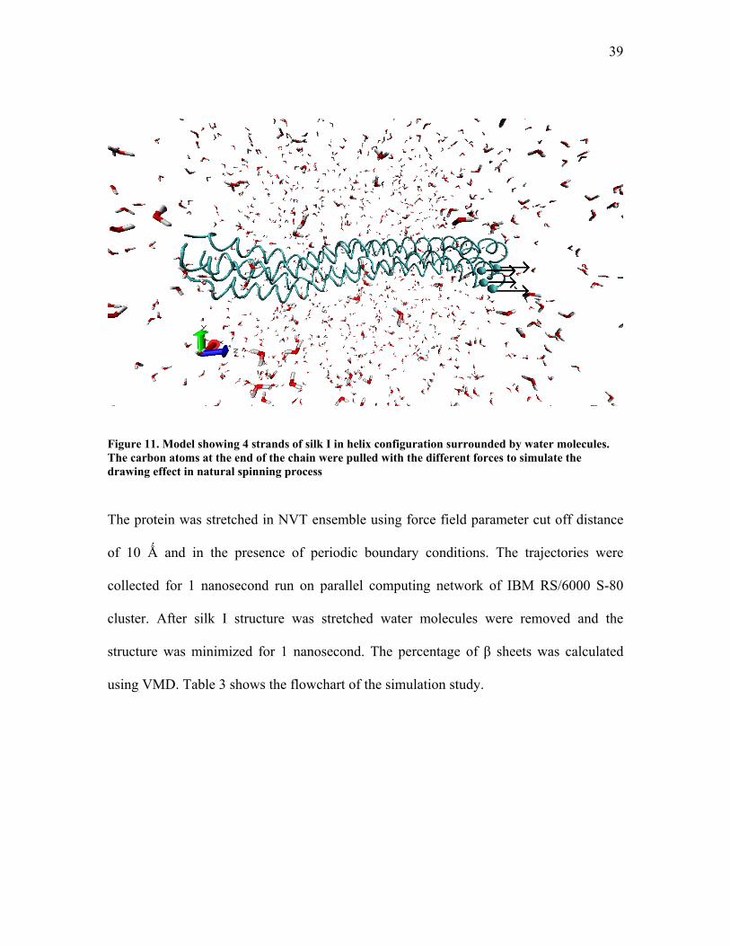
39
Figure 11. Model showing 4 strands of silk I in helix configuration surrounded by water molecules. The carbon atoms at the end of the chain were pulled with the different forces to simulate the drawing effect in natural spinning process
The protein was stretched in NVT ensemble using force field parameter cut off distance
of 10 Ǻ and in the presence of periodic boundary conditions. The trajectories were
collected for 1 nanosecond run on parallel computing network of IBM RS/6000 S-80
cluster. After silk I structure was stretched water molecules were removed and the
structure was minimized for 1 nanosecond. The percentage of β sheets was calculated
using VMD. Table 3 shows the flowchart of the simulation study.
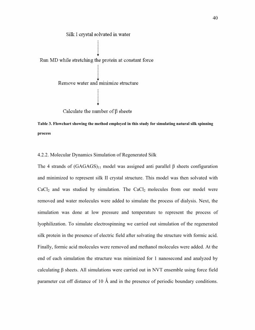
40
Table 3. Flowchart showing the method employed in this study for simulating natural silk spinning
process
4.2.2. Molecular Dynamics Simulation of Regenerated Silk
The 4 strands of (GAGAGS)11 model was assigned anti parallel β sheets configuration
and minimized to represent silk II crystal structure. This model was then solvated with
CaCl2 and was studied by simulation. The CaCl2 molecules from our model were
removed and water molecules were added to simulate the process of dialysis. Next, the
simulation was done at low pressure and temperature to represent the process of
lyophilization. To simulate electrospinning we carried out simulation of the regenerated
silk protein in the presence of electric field after solvating the structure with formic acid.
Finally, formic acid molecules were removed and methanol molecules were added. At the
end of each simulation the structure was minimized for 1 nanosecond and analyzed by
calculating β sheets. All simulations were carried out in NVT ensemble using force field
parameter cut off distance of 10 Ǻ and in the presence of periodic boundary conditions.
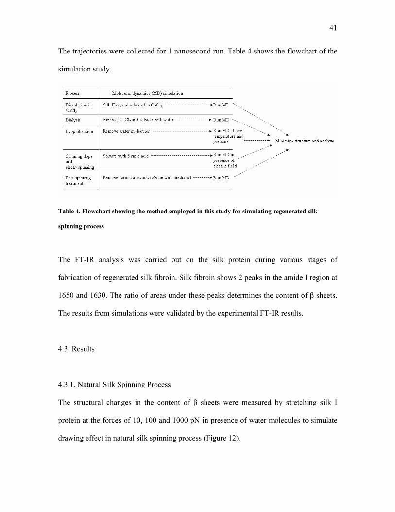
41
The trajectories were collected for 1 nanosecond run. Table 4 shows the flowchart of the
simulation study.
Table 4. Flowchart showing the method employed in this study for simulating regenerated silk
spinning process
The FT-IR analysis was carried out on the silk protein during various stages of
fabrication of regenerated silk fibroin. Silk fibroin shows 2 peaks in the amide I region at
1650 and 1630. The ratio of areas under these peaks determines the content of β sheets.
The results from simulations were validated by the experimental FT-IR results.
4.3. Results
4.3.1. Natural Silk Spinning Process
The structural changes in the content of β sheets were measured by stretching silk I
protein at the forces of 10, 100 and 1000 pN in presence of water molecules to simulate
drawing effect in natural silk spinning process (Figure 12).
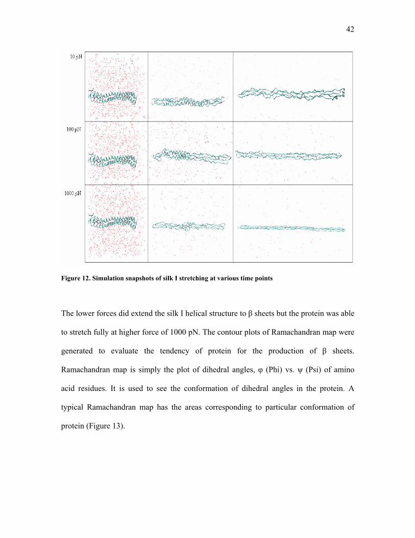
42
Figure 12. Simulation snapshots of silk I stretching at various time points
The lower forces did extend the silk I helical structure to β sheets but the protein was able
to stretch fully at higher force of 1000 pN. The contour plots of Ramachandran map were
generated to evaluate the tendency of protein for the production of β sheets.
Ramachandran map is simply the plot of dihedral angles, φ (Phi) vs. ψ (Psi) of amino
acid residues. It is used to see the conformation of dihedral angles in the protein. A
typical Ramachandran map has the areas corresponding to particular conformation of
protein (Figure 13).
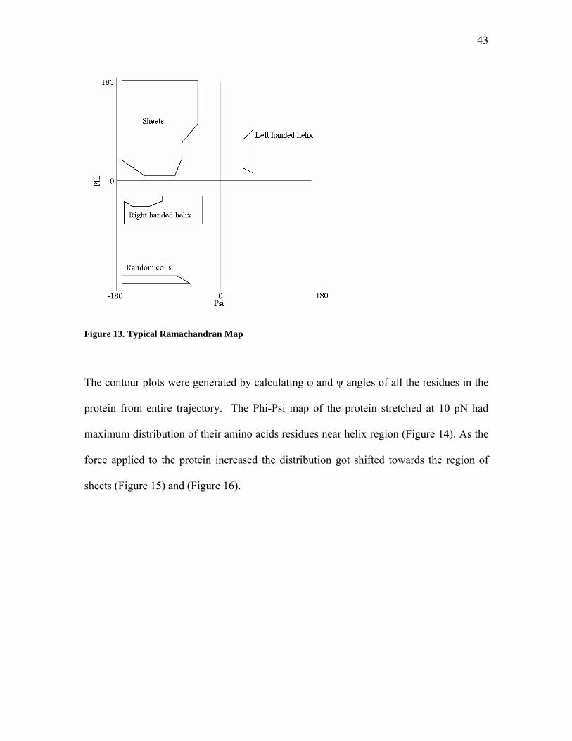
43
Figure 13. Typical Ramachandran Map
The contour plots were generated by calculating φ and ψ angles of all the residues in the
protein from entire trajectory. The Phi-Psi map of the protein stretched at 10 pN had
maximum distribution of their amino acids residues near helix region (Figure 14). As the
force applied to the protein increased the distribution got shifted towards the region of
sheets (Figure 15) and (Figure 16).
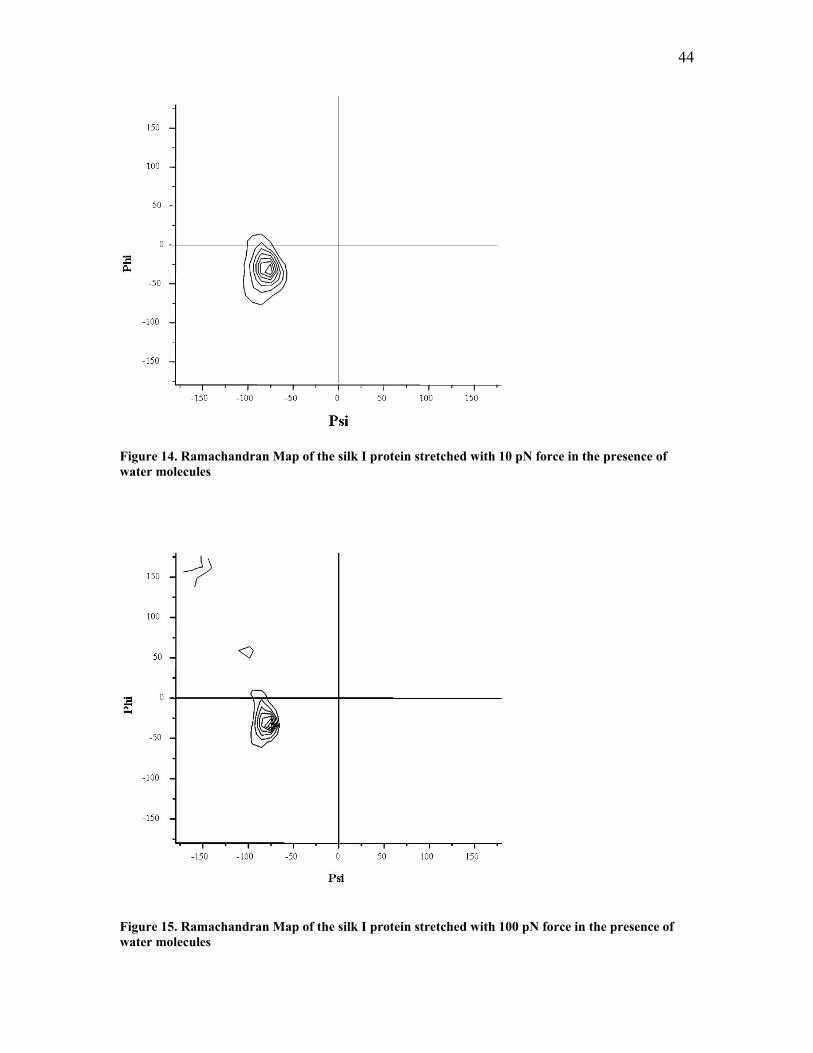
44
Figure 14. Ramachandran Map of the silk I protein stretched with 10 pN force in the presence of water molecules
Figure 15. Ramachandran Map of the silk I protein stretched with 100 pN force in the presence of water molecules
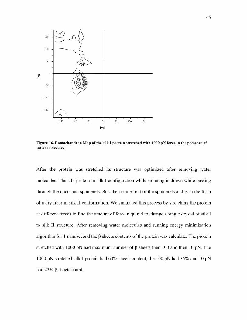
45
Figure 16. Ramachandran Map of the silk I protein stretched with 1000 pN force in the presence of water molecules
After the protein was stretched its structure was optimized after removing water
molecules. The silk protein in silk I configuration while spinning is drawn while passing
through the ducts and spinnerets. Silk then comes out of the spinnerets and is in the form
of a dry fiber in silk II conformation. We simulated this process by stretching the protein
at different forces to find the amount of force required to change a single crystal of silk I
to silk II structure. After removing water molecules and running energy minimization
algorithm for 1 nanosecond the β sheets contents of the protein was calculate. The protein
stretched with 1000 pN had maximum number of β sheets then 100 and then 10 pN. The
1000 pN stretched silk I protein had 60% sheets content, the 100 pN had 35% and 10 pN
had 23% β sheets count.
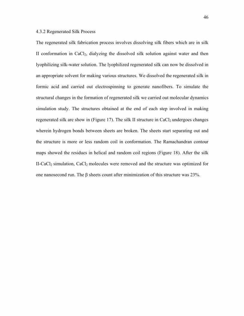
46
4.3.2 Regenerated Silk Process
The regenerated silk fabrication process involves dissolving silk fibers which are in silk
II conformation in CaCl2, dialyzing the dissolved silk solution against water and then
lyophilizing silk-water solution. The lyophilized regenerated silk can now be dissolved in
an appropriate solvent for making various structures. We dissolved the regenerated silk in
formic acid and carried out electrospinning to generate nanofibers. To simulate the
structural changes in the formation of regenerated silk we carried out molecular dynamics
simulation study. The structures obtained at the end of each step involved in making
regenerated silk are show in (Figure 17). The silk II structure in CaCl2 undergoes changes
wherein hydrogen bonds between sheets are broken. The sheets start separating out and
the structure is more or less random coil in conformation. The Ramachandran contour
maps showed the residues in helical and random coil regions (Figure 18). After the silk
II-CaCl2 simulation, CaCl2 molecules were removed and the structure was optimized for
one nanosecond run. The β sheets count after minimization of this structure was 23%.
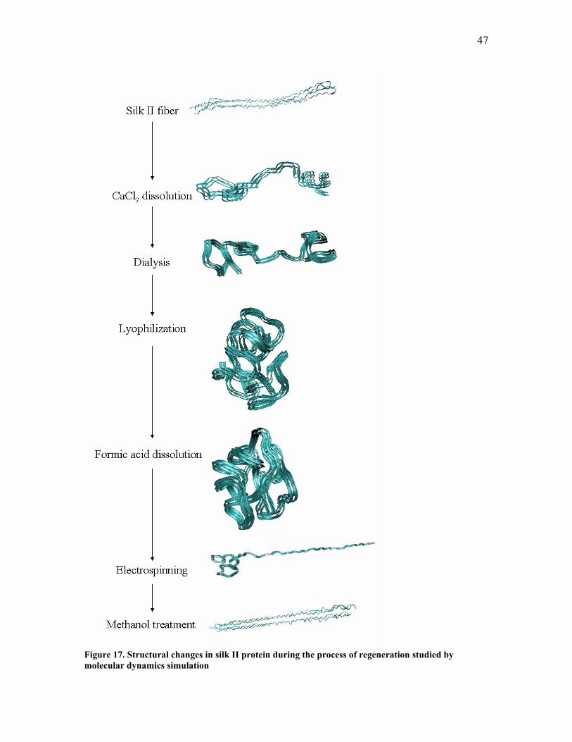
47
Figure 17. Structural changes in silk II protein during the process of regeneration studied by molecular dynamics simulation
48
Figure 18. Ramachandran Map of silk II protein during interaction with calcium
Next, the structure obtained during previous simulation was solvated with water
molecules to simulate the dialysis process wherein CaCl2 goes out and water comes in
through the dialysis tube. The hydrogen bonds start forming back again but the structure
is still more random in nature as can be seen from Ramachandran contour plot (Figure
19).
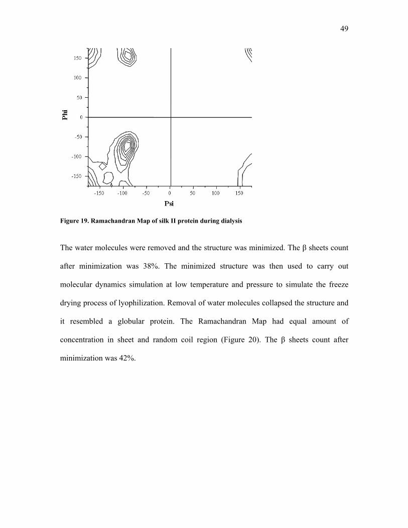
49
Figure 19. Ramachandran Map of silk II protein during dialysis The water molecules were removed and the structure was minimized. The β sheets count
after minimization was 38%. The minimized structure was then used to carry out
molecular dynamics simulation at low temperature and pressure to simulate the freeze
drying process of lyophilization. Removal of water molecules collapsed the structure and
it resembled a globular protein. The Ramachandran Map had equal amount of
concentration in sheet and random coil region (Figure 20). The β sheets count after
minimization was 42%.
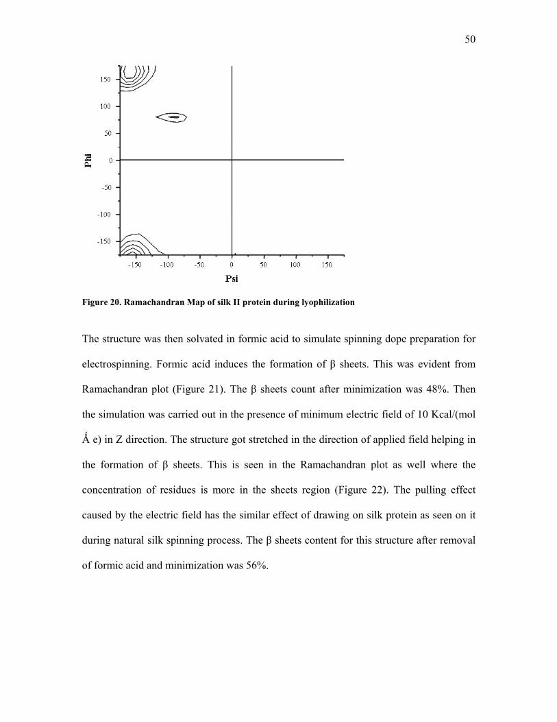
50
Figure 20. Ramachandran Map of silk II protein during lyophilization
The structure was then solvated in formic acid to simulate spinning dope preparation for
electrospinning. Formic acid induces the formation of β sheets. This was evident from
Ramachandran plot (Figure 21). The β sheets count after minimization was 48%. Then
the simulation was carried out in the presence of minimum electric field of 10 Kcal/(mol
Ǻ e) in Z direction. The structure got stretched in the direction of applied field helping in
the formation of β sheets. This is seen in the Ramachandran plot as well where the
concentration of residues is more in the sheets region (Figure 22). The pulling effect
caused by the electric field has the similar effect of drawing on silk protein as seen on it
during natural silk spinning process. The β sheets content for this structure after removal
of formic acid and minimization was 56%.
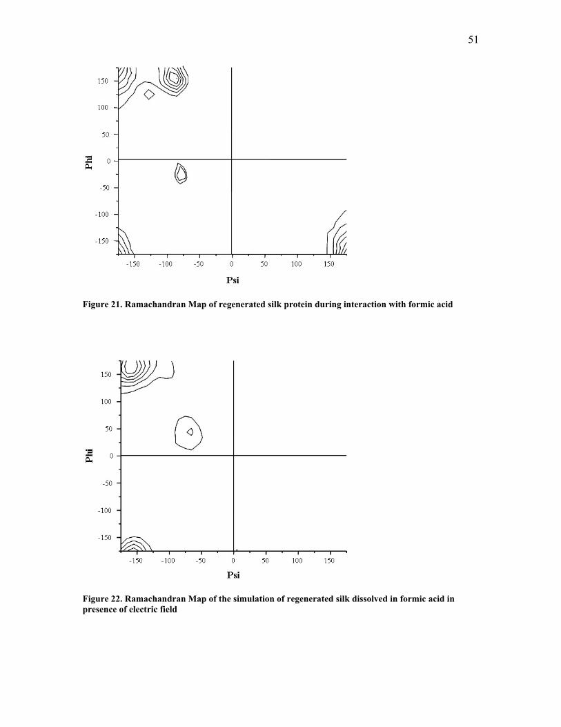
51
Figure 21. Ramachandran Map of regenerated silk protein during interaction with formic acid
Figure 22. Ramachandran Map of the simulation of regenerated silk dissolved in formic acid in presence of electric field
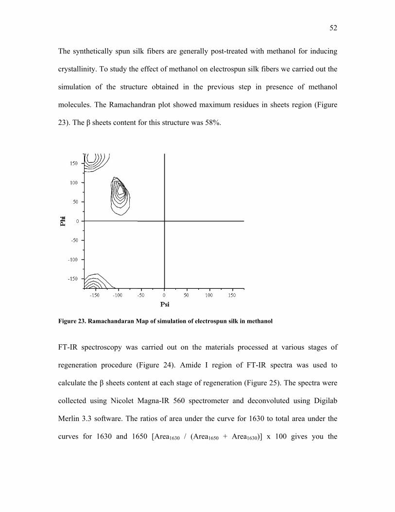
52
The synthetically spun silk fibers are generally post-treated with methanol for inducing
crystallinity. To study the effect of methanol on electrospun silk fibers we carried out the
simulation of the structure obtained in the previous step in presence of methanol
molecules. The Ramachandran plot showed maximum residues in sheets region (Figure
23). The β sheets content for this structure was 58%.
Figure 23. Ramachandaran Map of simulation of electrospun silk in methanol
FT-IR spectroscopy was carried out on the materials processed at various stages of
regeneration procedure (Figure 24). Amide I region of FT-IR spectra was used to
calculate the β sheets content at each stage of regeneration (Figure 25). The spectra were
collected using Nicolet Magna-IR 560 spectrometer and deconvoluted using Digilab
Merlin 3.3 software. The ratios of area under the curve for 1630 to total area under the
curves for 1630 and 1650 [Area1630 / (Area1650 + Area1630)] x 100 gives you the
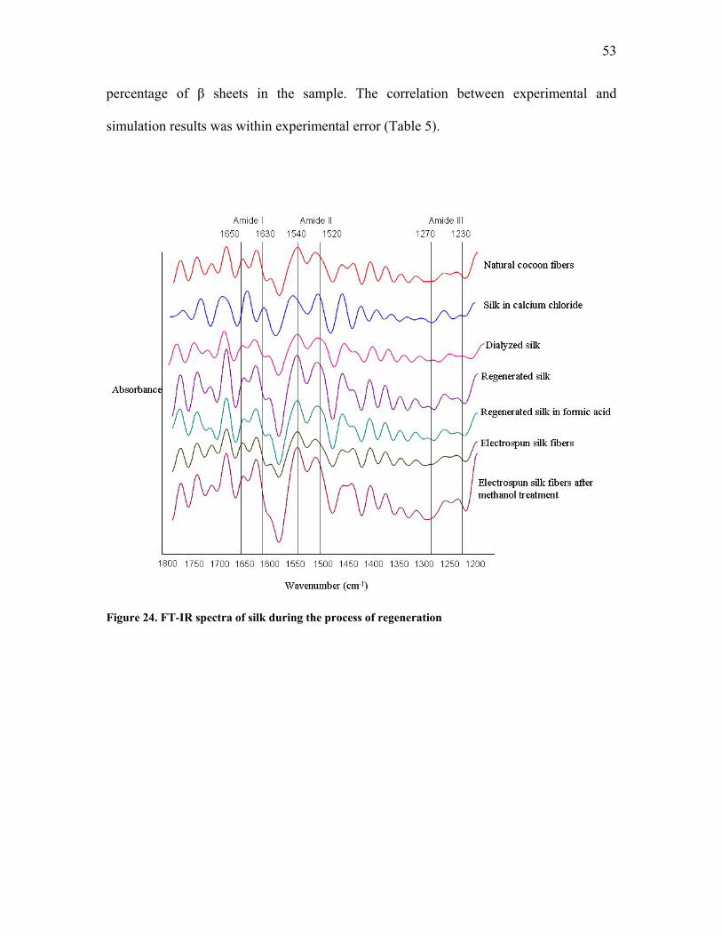
53
percentage of β sheets in the sample. The correlation between experimental and
simulation results was within experimental error (Table 5).
Figure 24. FT-IR spectra of silk during the process of regeneration
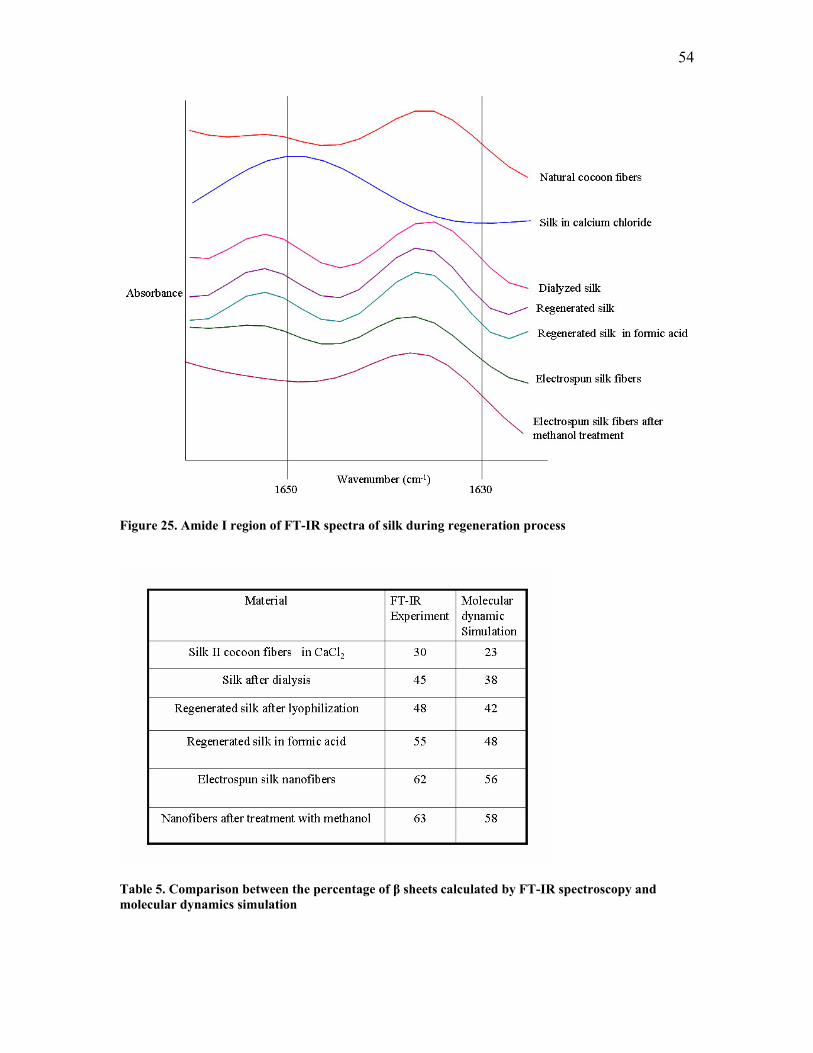
54
Figure 25. Amide I region of FT-IR spectra of silk during regeneration process
Table 5. Comparison between the percentage of β sheets calculated by FT-IR spectroscopy and molecular dynamics simulation
55
4.4. Summary
Structural changes in silk protein during natural spinning and electrospinning process
were studied by molecular dynamics simulation. The silk protein exists in 2 forms, silk I
and silk II. Silk I is the helical protein present in the silk glands prior to spinning. It is
water soluble and undergoes a structural change to water insoluble silk II protein which is
a fiber in β sheets form. The transition from silk I to silk II is known to occur because of
the drawing effect on the silk produced by external forces. We carried out the simulation
of silk I in the presence of pulling forces of 10, 100 and 1000 pN. The higher force of
1000 pN is required for the 65% conversion of silk I to silk II. The water insoluble silk II
fibers are converted to regenerated silk protein in order to utilize them for various
applications. The simulation was carried out on silk II protein going through each step of
regeneration process in order to study structural changes in these synthetically
manufactured fibers. Our simulation results suggested that silk II is converted to random
structure after dissolution in CaCl2. The β sheets content increases steadily thereafter in
the process of regeneration. We have used regenerated silk to fabricate nanofibers using
electrospinning. The regenerated silk was first dissolved is formic acid and then
electrospun in the presence of electric field. The nanofibers were then treated with
methanol. The simulation for electrospinning process was carried out as well. Based on
our results we concluded that formic acid helps in the formation of β sheets in the
spinning dope. Electrospinning induces the drawing effect on the silk protein because of
the electric field. Methanol induces β sheets formation in the electrospun nanofibers. The
results of the simulation were compared with experimental FT-IR results. They were
found to be in good agreement with each other. Electrospun silk fibers do not have

56
structure exactly similar to the natural cocoon fibers but it is a fast and economic way of
producing silk fibers. The detail optimization of electrospinning process, characterization
of nanofibers and their use as Tissue Engineering scaffolds for bone are discussed in next
chapter.
57
CHAPTER 5: NANOFIBROUS SCAFFOLDS FROM SILKWORM SILK
5.1. Introduction
Biocompatible and biodegradable synthetic polymeric materials are used to develop
biological scaffolds [9, 12, 80, 83, 106-110]. However, many of these scaffolding
materials have insufficient mechanical integrity and often induce an inflammatory
response [111-114]. The superior mechanical properties of silk fibers and possibility of
enhanced biocompatibility, makes it an ideal candidate for scaffolds fabrication [16, 28,
42, 115]. The natural living systems are made up of fibrils at nanoscale levels and
organized in a hierarchical manner. The scaffolds for the Tissue Engineering application
should mimic the natural extracellular matrix and should be fibrous as well as nano scale
with fiber architectures conducive to cell deposition and cell proliferation.
Electrospinning is a unique method capable of producing nanoscale fibers from both
synthetic as well as natural polymers for biomedical applications [14, 15, 116, 117]. The
use of electrospinning in the fabrication of various nonwoven materials was first reported
in 1934 [118] but it was not until recently that it became a popular method for scaffolds
fabrication [14]. The scientific understanding of the materials at nanoscale levels allows
us to control the basic properties of materials without changing their chemical
composition. Utilization of this technology presents the opportunity to develop new
families of products for biomedical and biotechnology applications. Nanofibers have
unique properties which include high surface area to volume ratio, superior strength,
surface energy, as well as thermal and electrical conductivity. Silkworm silk is
58
abundantly available from the cocoons of Bombyx mori raised by sericulture. Silk fibers
can be regenerated and converted to various forms including films, powders and
filaments [43, 44, 119] to create new geometric and functional properties which are
unavailable in the natural silk fiber. This regenerated silk protein can be transformed to
nanofibers using electrospinning technique. Attempts were made by Zarkoob et al [120]
to electrospin natural cocoon fibers. Silk fibers with diameters in the range of 6.5–200 nm
were produced with crystallographic order equivalent to that of the original natural fibers
but it took 5 months to dissolve natural fibers in Hexafluoro isopropanol (HFIP). The use
of regenerated silk protein alleviates this problem. The process of regeneration involves
dissolving silk fibers in a concentrated salt solution then dialyzing to remove salt. Jin et al
[117] made various blends of dialyzed silk and polyethylene oxide (PEO) to make a
spinnable solution for electrospinning. The uniform fibers (700±50 nm) were obtained
but this technique involves the use of PEO which has to be removed from nanofiber mats
before cell-scaffolds interaction study. We lyophilized the dialyzed silk solution to make
a regenerated silk sponge which can be dissolved in an appropriate solvent to carry out
electrospinning. Thus electrospun nanofibers consisting of pure silk were fabricated. This
chapter of the thesis deals with the fabrication, process optimization and characterization
of nanofibrous scaffolds from regenerated silkworm silk. The spinning dope was
prepared by dissolving regenerated silk in formic acid and the electrospinning process
was optimized varying electric field, spinning distance and concentration to fabricate
continuous uniform fibers of 100 nm in diameter. The fibers were characterized for the
morphology and diameter distribution using Phillips XL-30 field emission environmental
scanning electron microscope (ESEM). Statistical analysis was carried out using SPSS 14
59
software package. The structural characterization was carried out by Nicolet Magna-IR
560 Fourier transform infra red spectroscopy (FT-IR), Raman spectroscopy (Renishaw
1000 using 780 nm diode laser) and Siemens D500 Wide angle x-ray diffraction
(WAXD) studies. The mechanical properties were determined by KES-G1 Kawabata
microtensile tester and cell-scaffolds interaction study was done using bovine osteoblasts
cells.
5.2. Materials and Methods
5.2.1. Regenerated Silk and Spinning Dope Preparation
Silk fibers were purchased from Taiwan Textile Research Institute (TTRI). The fibers
were boiled in aqueous 0.02 M Na2CO3 at 100 ºC for 30 min and rinsed with water to
extract sericin. These degummed fibers were dissolved in 50% aqueous CaCl2 at 100 ºC,
to obtain 6% silk solution. All concentration measurements were done in weight by
weight (w/w).The solution was poured into regenerated cellulose dialysis tubing (Fisher
Scientific: T3 membrane, pore size 25 Ǻ) to carry out dialysis against 1 liter of deionized
water for 48 h at 23 ºC. The regenerated silk fibroin sponge was obtained by
lyophilization (Labconco 2.5 FreezonePlus lyophilizer). The spinning dope was prepared
by dissolving regenerated silk sponge in formic acid.
5.2.2. Electrospinning Process Optimization and Characterization
The silk-formic acid spinning dope was transferred to 3 ml syringe with 18-G needle and
electrospun at a 45° spinning angle. The tip-to-collection plate (covered with aluminum
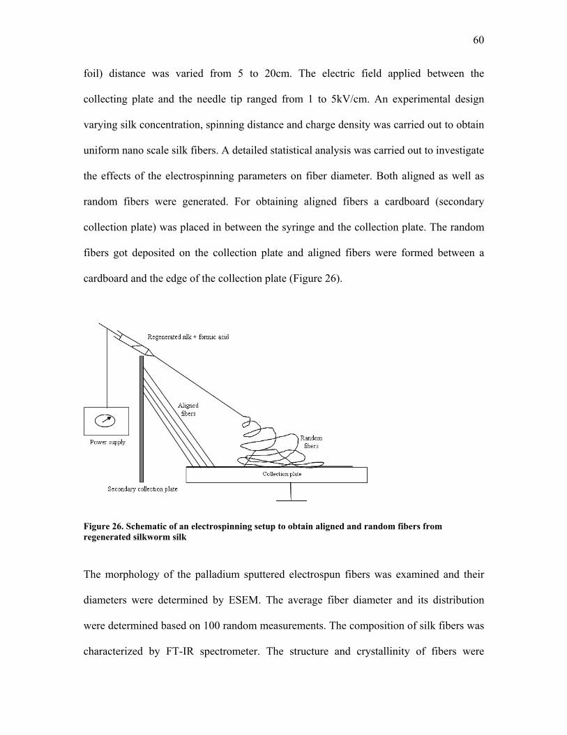
60
foil) distance was varied from 5 to 20cm. The electric field applied between the
collecting plate and the needle tip ranged from 1 to 5kV/cm. An experimental design
varying silk concentration, spinning distance and charge density was carried out to obtain
uniform nano scale silk fibers. A detailed statistical analysis was carried out to investigate
the effects of the electrospinning parameters on fiber diameter. Both aligned as well as
random fibers were generated. For obtaining aligned fibers a cardboard (secondary
collection plate) was placed in between the syringe and the collection plate. The random
fibers got deposited on the collection plate and aligned fibers were formed between a
cardboard and the edge of the collection plate (Figure 26).
Figure 26. Schematic of an electrospinning setup to obtain aligned and random fibers from regenerated silkworm silk
The morphology of the palladium sputtered electrospun fibers was examined and their
diameters were determined by ESEM. The average fiber diameter and its distribution
were determined based on 100 random measurements. The composition of silk fibers was
characterized by FT-IR spectrometer. The structure and crystallinity of fibers were
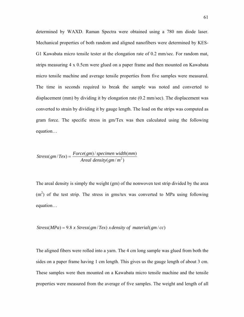
61
determined by WAXD. Raman Spectra were obtained using a 780 nm diode laser.
Mechanical properties of both random and aligned nanofibers were determined by KES-
G1 Kawabata micro tensile tester at the elongation rate of 0.2 mm/sec. For random mat,
strips measuring 4 x 0.5cm were glued on a paper frame and then mounted on Kawabata
micro tensile machine and average tensile properties from five samples were measured.
The time in seconds required to break the sample was noted and converted to
displacement (mm) by dividing it by elongation rate (0.2 mm/sec). The displacement was
converted to strain by dividing it by gauge length. The load on the strips was computed as
gram force. The specific stress in gm/Tex was then calculated using the following
equation…
)/()(/)()/( 2mgmdensityAreal
mmwidthspecimengmForceTexgmStress =
The areal density is simply the weight (gm) of the nonwoven test strip divided by the area
(m2) of the test strip. The stress in gms/tex was converted to MPa using following
equation…
)/()/(8.9)( ccgmmaterialofdensityxTexgmStressxMPaStress =
The aligned fibers were rolled into a yarn. The 4 cm long sample was glued from both the
sides on a paper frame having 1 cm length. This gives us the gauge length of about 3 cm.
These samples were then mounted on a Kawabata micro tensile machine and the tensile
properties were measured from the average of five samples. The weight and length of all
62
the yarns were measured prior to mounting them on a paper frame. The linear density of
the yarn expressed in the unit of denier (gm /9000 meter) was determined for each yarn.
The load on the yarn was normalized by the linear density to obtain the specific stress
expressed in gram force/denier. Knowing the density of the silk at 1.25 g/cc one can
determine the engineering stress in MPa.
5.2.3. Cell-scaffolds Interaction
All reagents were purchased from Sigma Aldrich unless otherwise mentioned. The
primary fetal bovine osteoblasts were maintained in culture using Dulbecco's Modified
Eagle's Medium (DMEM) supplemented with 10 % fetal bovine serum (FBS), 2 mM L-
glutamine, 10000 IU Penicillin, 10000 µg/ml Streptomycin and 25 µg/ml Amphotericin-
B. Approximately 1cm2 discs were punched out from the random nanofiber mats. The
natural cocoon silk fibers were used as well for comparison. For cell seeding on
scaffolds, cells from the tissue culture flasks were trypsinized for 5 minutes at 37°C,
neutralized with medium, centrifuged for 5 minutes at 1200 rpm and resuspended in
medium. Approximately 350000 cells were seeded per scaffold. The cells were
maintained in culture over the scaffolds for 4 weeks using the above mentioned cocktail
of medium in presence of 50 µg/ml ascorbic acid. The cell morphology, proliferation and
differentiation were observed at day 10, 20 and 30. Cell morphology was observed by
ESEM. The cell-scaffolds constructs were removed from the culture media on desired
days and were washed twice with 1x phosphate buffered saline (PBS) and then subjected
to a gradient of ethanol (20%, 50%, 70%, 90%, 100%), each for 10 minutes. They were
refrigerated overnight at 4°C. The scaffolds were then coated with palladium and
63
observed under ESEM. For cell proliferation Alamar Blue dye assay was carried out. The
assay is based on the principle that the growth of cells results into metabolic activities
which results into chemical reduction of Alamar Blue dye. The reduction in the dye leads
to the change in the color which can be read fluorometrically. The cell-scaffolds
constructs on the desired days were transferred to new culture plates. The Alamar Blue
(Invitrogen) dye (10% of culture medium) was added to the constructs and they were fed
with fresh media. They were then allowed to incubate for 4 hours. After the incubation
the fluorescence of the dye was read by Tecan GENios fluorescence cell counter. The
number of cells on the scaffolds was determined from the fluorescence of the dye using a
standard curve. Cell differentiation was studied by measuring alkaline phosphatase,
osteocalcin and calcium levels in cell-scaffolds constructs on 10, 20 and 30 days. For
measuring alkaline phosphatase activity, cell-scaffolds constructs were removed and were
washed with PBS. The cells from the scaffolds were extracted by 1% Triton X-100
(Fisher Scientific) for 60 mins. They were then centrifuged and the supernatant was used
to calculate alkaline phosphatase (ALP) activity by p-nitro phenyl phosphate (p-NPP)
method. Alkaline phosphatase catalyzes the cleavage of p-NPP to give p-Nitrophenol and
orthophosphate which develops a yellow color in the presence of a base. 0.5 ml of
supernatant and 0.5 ml of diluted p-NPP (100µl of p-NPP concentrate per 2 ml of 100
mM sodium bicarbonate/carbonate buffer, pH 10) were mixed and incubated for 45 mins.
The absorbance of this mixture was read at 405nm. The units of alkaline phosphatase per
liter were calculated using the following equation where 18.8 is the absorbance
coefficient of p-NPP.
)(8.181000)(min/)/(
mlvolumeSampleXXmlvolumeAssayXAbsorbanceLUephosphatasAlkaline =
64
The alkaline phosphatase activity was normalized with the number of cells determined
using Alamar Blue dye assay. Osteocalcin activity was measured by an Enzyme linked
immunoassay kit (Biomedical Technologies) following manufacturer’s protocols. The
assay is a sandwich immunoassay which employs two monoclonal antibodies directed
towards the amino and the carboxy terminal regions of the osteocalcin. Briefly, 25µl of
medium from the cell-scaffolds construct was added to the strip plates coated with the
primary antibodies. 100µl of secondary antibody was then added and incubated for 2.5
hours. They were then aspirated and washed thrice with a buffer. 100µl of streptavidin-
avidin horse radish peroxidase was then added to the plates and incubated again for 30
mins. Finally 100µl of substrate was added after washing the plates thrice with a buffer
and then were allowed to develop color in dark for 10 mins. After 10 mins 100µl of stop
solution was added and the absorbance was read at 450nm. The amount of osteocalcin
was calculated from the absorbance using a standard curve. For measuring calcium levels
in the cell-scaffolds constructs Calcium Test Kit (Stanbio Laboratories) was used and the
manufacturer’s protocols were followed. The cell lysate was prepared using 0.5ml Triton
X-100 and 0.5ml Trichloroacetic Acid. The assay is based on o-cresolphthalin
compexone method which develops a purple color in presence of calcium. The amount of
calcium was calculated from the standard curve. They were incubated for 60 mins and
centrifuged. The supernatant was used to calculate the calcium levels. 0.01 ml of
supernatant, 0.5 ml color reagent (o-cresolphthalin compexone) and 0.5 ml base reagent
(2-amino, 2-methyl, 1-propanol) were mixed and incubated for 10 mins. The absorbance
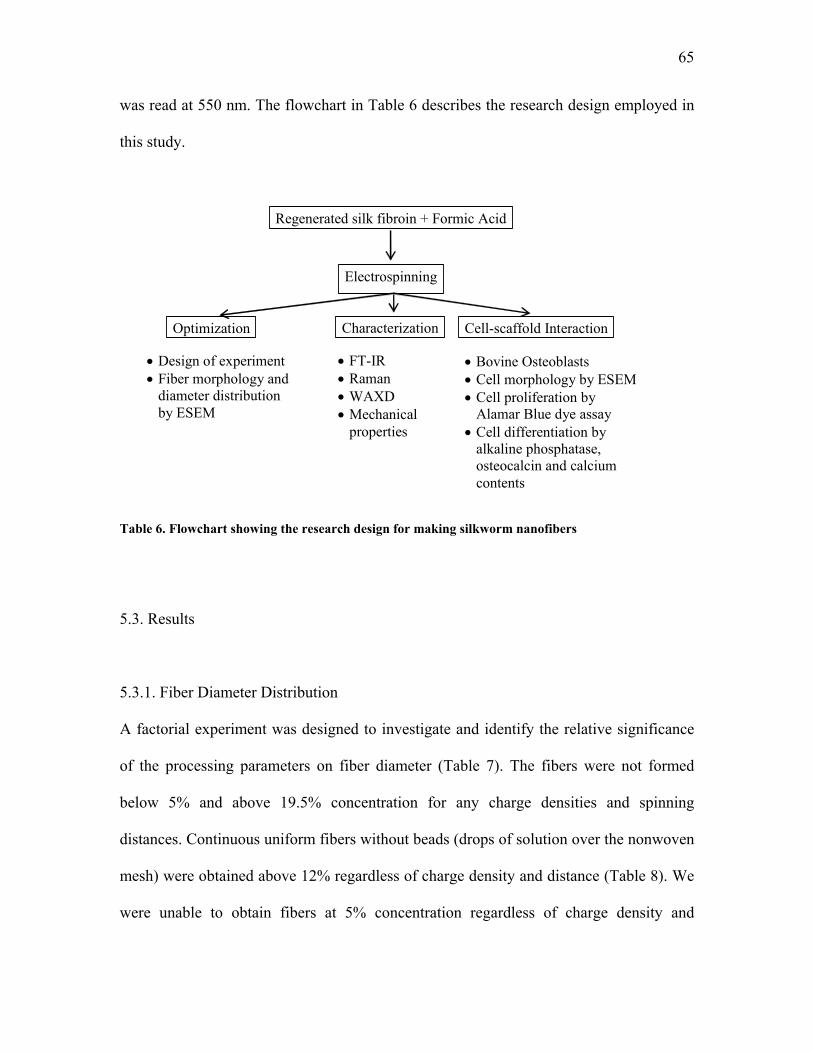
65
was read at 550 nm. The flowchart in Table 6 describes the research design employed in
this study.
• Design of experiment • Fiber morphology and
diameter distribution by ESEM
Regenerated silk fibroin + Formic Acid
Electrospinning
Cell-scaffold Interaction CharacterizationOptimization
• FT-IR • Raman • WAXD • Mechanical
properties
• Bovine Osteoblasts • Cell morphology by ESEM • Cell proliferation by
Alamar Blue dye assay • Cell differentiation by
alkaline phosphatase, osteocalcin and calcium contents
Table 6. Flowchart showing the research design for making silkworm nanofibers
5.3. Results
5.3.1. Fiber Diameter Distribution
A factorial experiment was designed to investigate and identify the relative significance
of the processing parameters on fiber diameter (Table 7). The fibers were not formed
below 5% and above 19.5% concentration for any charge densities and spinning
distances. Continuous uniform fibers without beads (drops of solution over the nonwoven
mesh) were obtained above 12% regardless of charge density and distance (Table 8). We
were unable to obtain fibers at 5% concentration regardless of charge density and
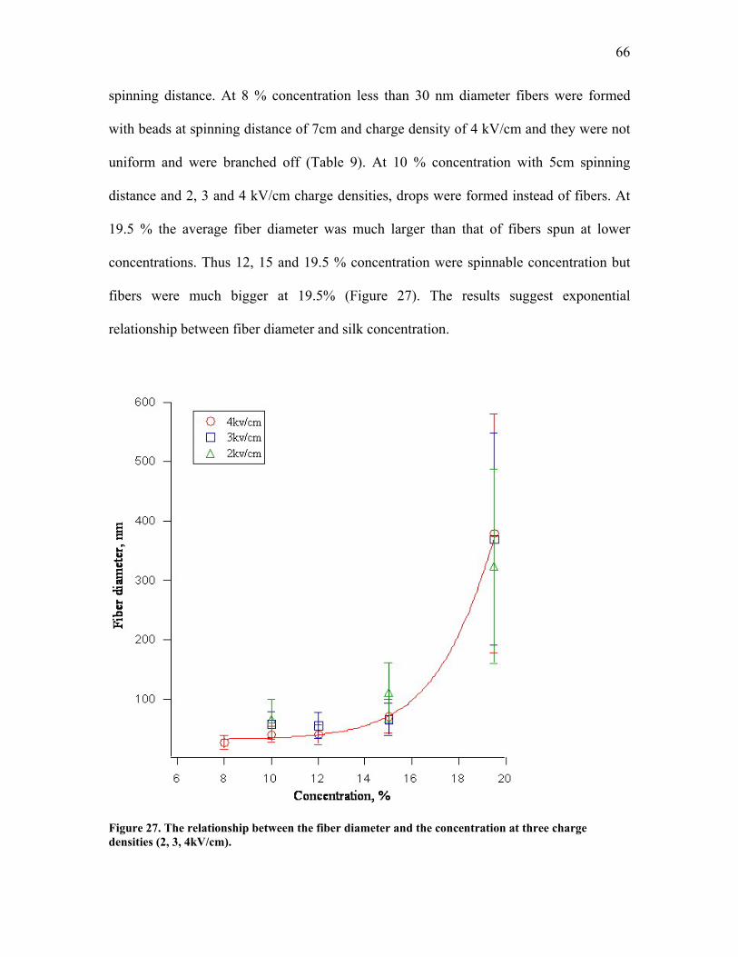
66
spinning distance. At 8 % concentration less than 30 nm diameter fibers were formed
with beads at spinning distance of 7cm and charge density of 4 kV/cm and they were not
uniform and were branched off (Table 9). At 10 % concentration with 5cm spinning
distance and 2, 3 and 4 kV/cm charge densities, drops were formed instead of fibers. At
19.5 % the average fiber diameter was much larger than that of fibers spun at lower
concentrations. Thus 12, 15 and 19.5 % concentration were spinnable concentration but
fibers were much bigger at 19.5% (Figure 27). The results suggest exponential
relationship between fiber diameter and silk concentration.
Figure 27. The relationship between the fiber diameter and the concentration at three charge densities (2, 3, 4kV/cm).
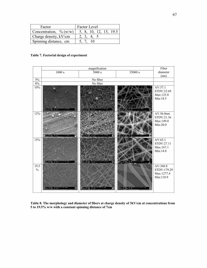
67
Factor Factor Level Concentration, % (w/w) 5, 8, 10, 12, 15, 19.5Charge density, kV/cm 2, 3, 4, 5 Spinning distance, cm 5, 7, 10
Table 7. Factorial design of experiment
magnification 1000 x 5000 x 35000 x
Fiber diameter
(nm) 5% No fiber 8% No fiber
10%
AV:57.1 STDV:22.69 Max:125.8 Min:18.5
12%
AV.56.0nm STDV:21.36 Max:149.0 Min:20.0
15%
AV:65.1 STDV:27.11 Max:167.1 Min:14.8
19.5 %
AV:368.8 STDV:179.29Max:1277.4 Min:110.9
Table 8. The morphology and diameter of fibers at charge density of 3kV/cm at concentrations from 5 to 19.5% w/w with a constant spinning distance of 7cm
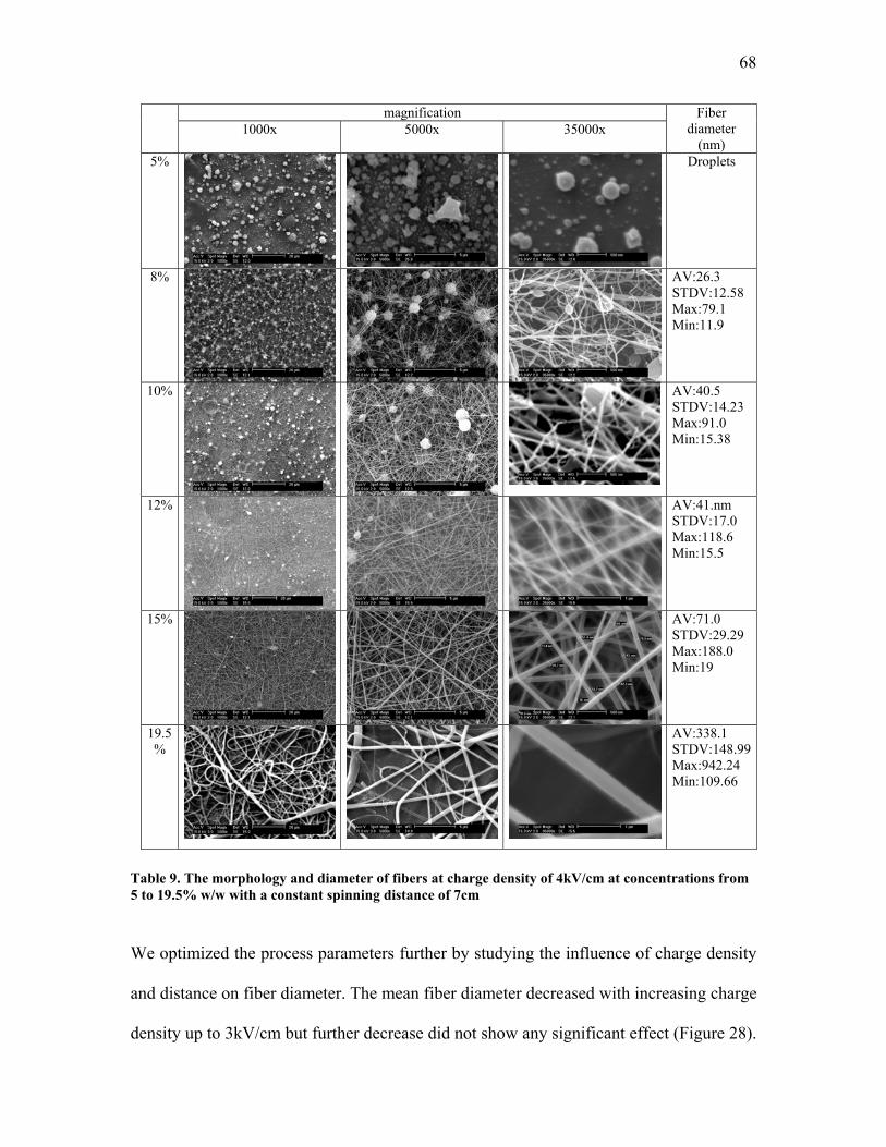
68
magnification 1000x 5000x 35000x
Fiber diameter
(nm) 5%
Droplets
8%
AV:26.3 STDV:12.58 Max:79.1 Min:11.9
10%
AV:40.5 STDV:14.23 Max:91.0 Min:15.38
12%
AV:41.nm STDV:17.0 Max:118.6 Min:15.5
15%
AV:71.0 STDV:29.29 Max:188.0 Min:19
19.5 %
AV:338.1 STDV:148.99Max:942.24 Min:109.66
Table 9. The morphology and diameter of fibers at charge density of 4kV/cm at concentrations from 5 to 19.5% w/w with a constant spinning distance of 7cm
We optimized the process parameters further by studying the influence of charge density
and distance on fiber diameter. The mean fiber diameter decreased with increasing charge
density up to 3kV/cm but further decrease did not show any significant effect (Figure 28).
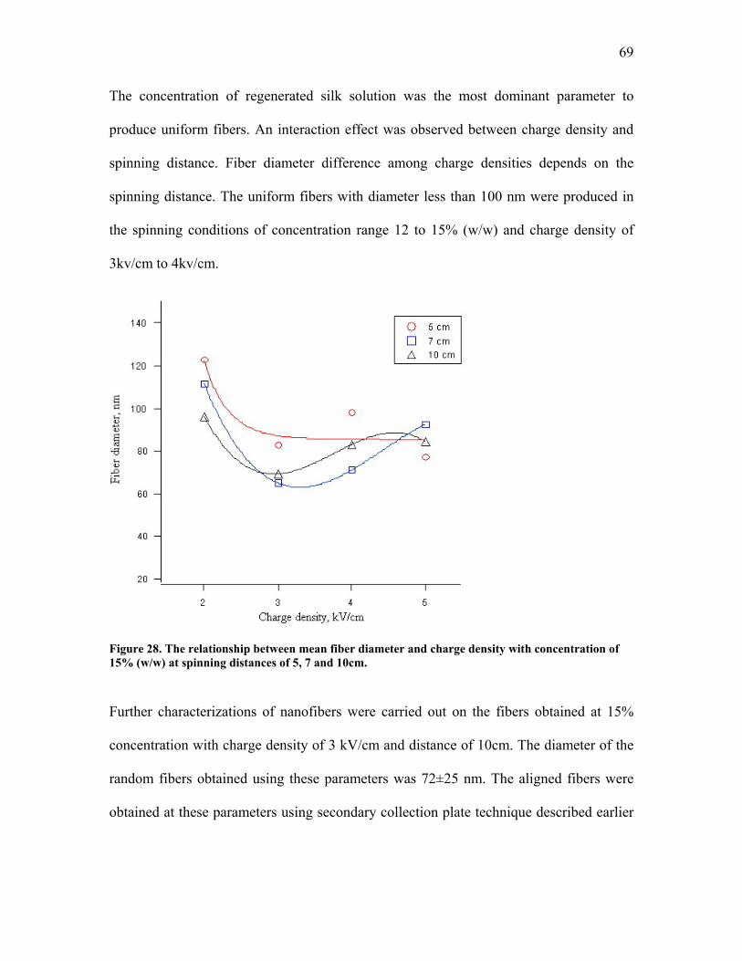
69
The concentration of regenerated silk solution was the most dominant parameter to
produce uniform fibers. An interaction effect was observed between charge density and
spinning distance. Fiber diameter difference among charge densities depends on the
spinning distance. The uniform fibers with diameter less than 100 nm were produced in
the spinning conditions of concentration range 12 to 15% (w/w) and charge density of
3kv/cm to 4kv/cm.
Figure 28. The relationship between mean fiber diameter and charge density with concentration of 15% (w/w) at spinning distances of 5, 7 and 10cm.
Further characterizations of nanofibers were carried out on the fibers obtained at 15%
concentration with charge density of 3 kV/cm and distance of 10cm. The diameter of the
random fibers obtained using these parameters was 72±25 nm. The aligned fibers were
obtained at these parameters using secondary collection plate technique described earlier
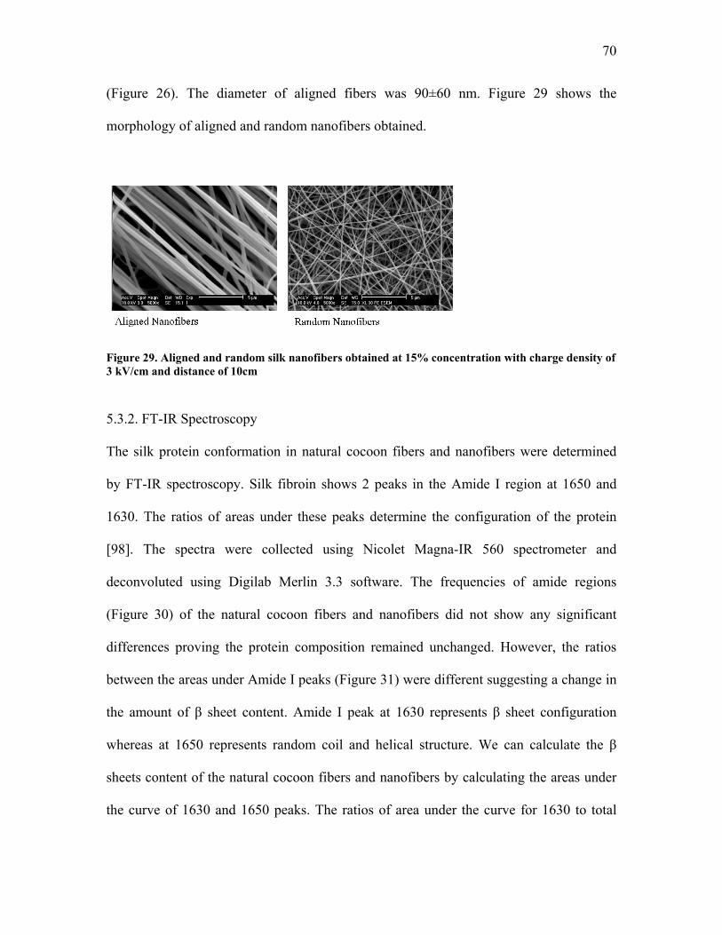
70
(Figure 26). The diameter of aligned fibers was 90±60 nm. Figure 29 shows the
morphology of aligned and random nanofibers obtained.
Figure 29. Aligned and random silk nanofibers obtained at 15% concentration with charge density of 3 kV/cm and distance of 10cm 5.3.2. FT-IR Spectroscopy
The silk protein conformation in natural cocoon fibers and nanofibers were determined
by FT-IR spectroscopy. Silk fibroin shows 2 peaks in the Amide I region at 1650 and
1630. The ratios of areas under these peaks determine the configuration of the protein
[98]. The spectra were collected using Nicolet Magna-IR 560 spectrometer and
deconvoluted using Digilab Merlin 3.3 software. The frequencies of amide regions
(Figure 30) of the natural cocoon fibers and nanofibers did not show any significant
differences proving the protein composition remained unchanged. However, the ratios
between the areas under Amide I peaks (Figure 31) were different suggesting a change in
the amount of β sheet content. Amide I peak at 1630 represents β sheet configuration
whereas at 1650 represents random coil and helical structure. We can calculate the β
sheets content of the natural cocoon fibers and nanofibers by calculating the areas under
the curve of 1630 and 1650 peaks. The ratios of area under the curve for 1630 to total
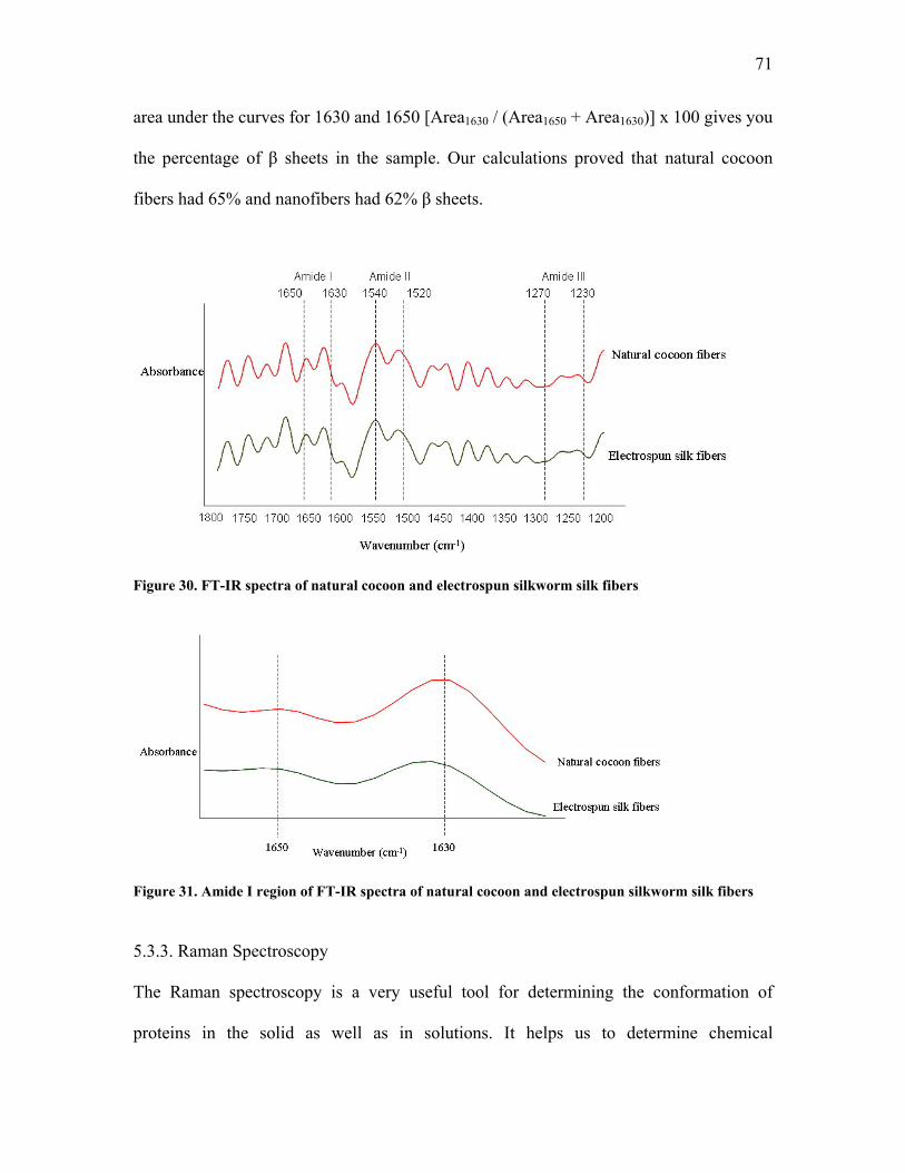
71
area under the curves for 1630 and 1650 [Area1630 / (Area1650 + Area1630)] x 100 gives you
the percentage of β sheets in the sample. Our calculations proved that natural cocoon
fibers had 65% and nanofibers had 62% β sheets.
Figure 30. FT-IR spectra of natural cocoon and electrospun silkworm silk fibers
Figure 31. Amide I region of FT-IR spectra of natural cocoon and electrospun silkworm silk fibers
5.3.3. Raman Spectroscopy
The Raman spectroscopy is a very useful tool for determining the conformation of
proteins in the solid as well as in solutions. It helps us to determine chemical
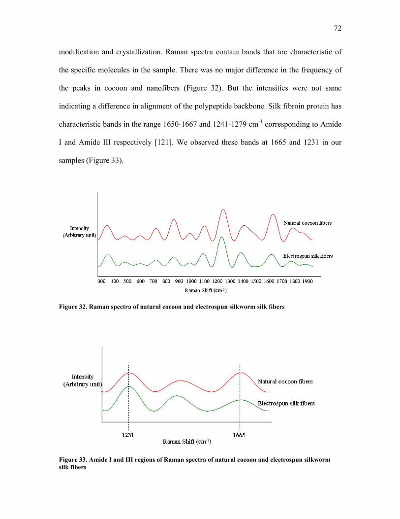
72
modification and crystallization. Raman spectra contain bands that are characteristic of
the specific molecules in the sample. There was no major difference in the frequency of
the peaks in cocoon and nanofibers (Figure 32). But the intensities were not same
indicating a difference in alignment of the polypeptide backbone. Silk fibroin protein has
characteristic bands in the range 1650-1667 and 1241-1279 cm-1 corresponding to Amide
I and Amide III respectively [121]. We observed these bands at 1665 and 1231 in our
samples (Figure 33).
Figure 32. Raman spectra of natural cocoon and electrospun silkworm silk fibers
Figure 33. Amide I and III regions of Raman spectra of natural cocoon and electrospun silkworm silk fibers
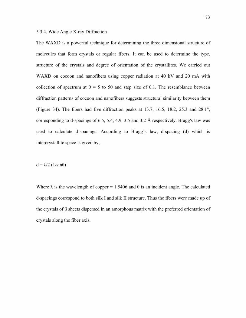
73
5.3.4. Wide Angle X-ray Diffraction
The WAXD is a powerful technique for determining the three dimensional structure of
molecules that form crystals or regular fibers. It can be used to determine the type,
structure of the crystals and degree of orientation of the crystallites. We carried out
WAXD on cocoon and nanofibers using copper radiation at 40 kV and 20 mA with
collection of spectrum at θ = 5 to 50 and step size of 0.1. The resemblance between
diffraction patterns of cocoon and nanofibers suggests structural similarity between them
(Figure 34). The fibers had five diffraction peaks at 13.7, 16.5, 18.2, 25.3 and 28.1°,
corresponding to d-spacings of 6.5, 5.4, 4.9, 3.5 and 3.2 Å respectively. Bragg's law was
used to calculate d-spacings. According to Bragg’s law, d-spacing (d) which is
intercrystallite space is given by,
d = λ/2 (1/sinθ)
Where λ is the wavelength of copper = 1.5406 and θ is an incident angle. The calculated
d-spacings correspond to both silk I and silk II structure. Thus the fibers were made up of
the crystals of β sheets dispersed in an amorphous matrix with the preferred orientation of
crystals along the fiber axis.
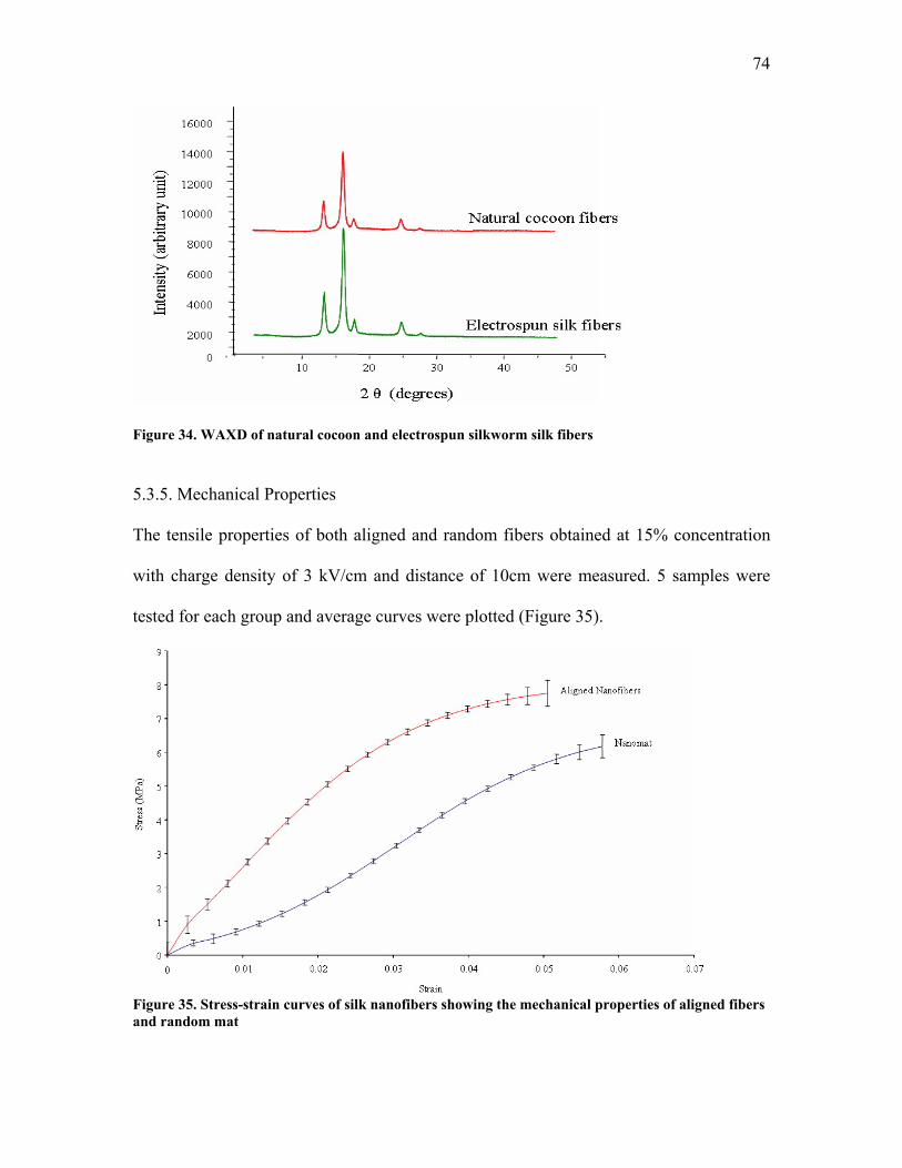
74
Figure 34. WAXD of natural cocoon and electrospun silkworm silk fibers
5.3.5. Mechanical Properties
The tensile properties of both aligned and random fibers obtained at 15% concentration
with charge density of 3 kV/cm and distance of 10cm were measured. 5 samples were
tested for each group and average curves were plotted (Figure 35).
Figure 35. Stress-strain curves of silk nanofibers showing the mechanical properties of aligned fibers and random mat
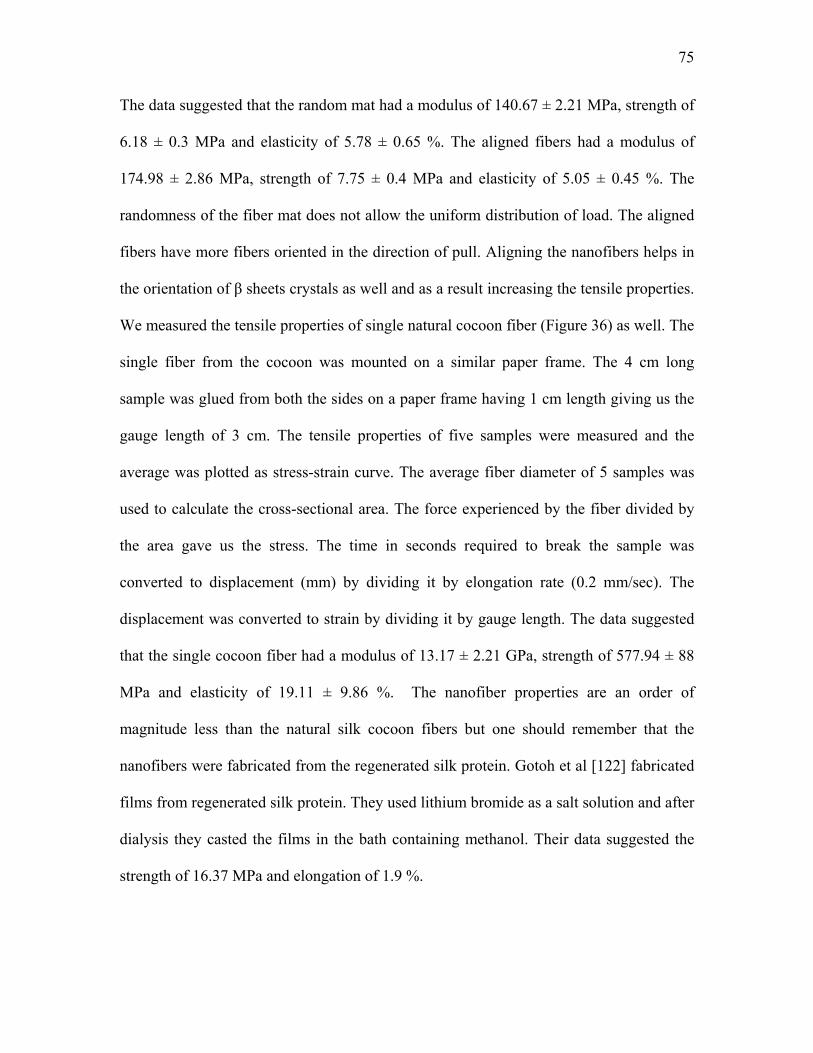
75
The data suggested that the random mat had a modulus of 140.67 ± 2.21 MPa, strength of
6.18 ± 0.3 MPa and elasticity of 5.78 ± 0.65 %. The aligned fibers had a modulus of
174.98 ± 2.86 MPa, strength of 7.75 ± 0.4 MPa and elasticity of 5.05 ± 0.45 %. The
randomness of the fiber mat does not allow the uniform distribution of load. The aligned
fibers have more fibers oriented in the direction of pull. Aligning the nanofibers helps in
the orientation of β sheets crystals as well and as a result increasing the tensile properties.
We measured the tensile properties of single natural cocoon fiber (Figure 36) as well. The
single fiber from the cocoon was mounted on a similar paper frame. The 4 cm long
sample was glued from both the sides on a paper frame having 1 cm length giving us the
gauge length of 3 cm. The tensile properties of five samples were measured and the
average was plotted as stress-strain curve. The average fiber diameter of 5 samples was
used to calculate the cross-sectional area. The force experienced by the fiber divided by
the area gave us the stress. The time in seconds required to break the sample was
converted to displacement (mm) by dividing it by elongation rate (0.2 mm/sec). The
displacement was converted to strain by dividing it by gauge length. The data suggested
that the single cocoon fiber had a modulus of 13.17 ± 2.21 GPa, strength of 577.94 ± 88
MPa and elasticity of 19.11 ± 9.86 %. The nanofiber properties are an order of
magnitude less than the natural silk cocoon fibers but one should remember that the
nanofibers were fabricated from the regenerated silk protein. Gotoh et al [122] fabricated
films from regenerated silk protein. They used lithium bromide as a salt solution and after
dialysis they casted the films in the bath containing methanol. Their data suggested the
strength of 16.37 MPa and elongation of 1.9 %.
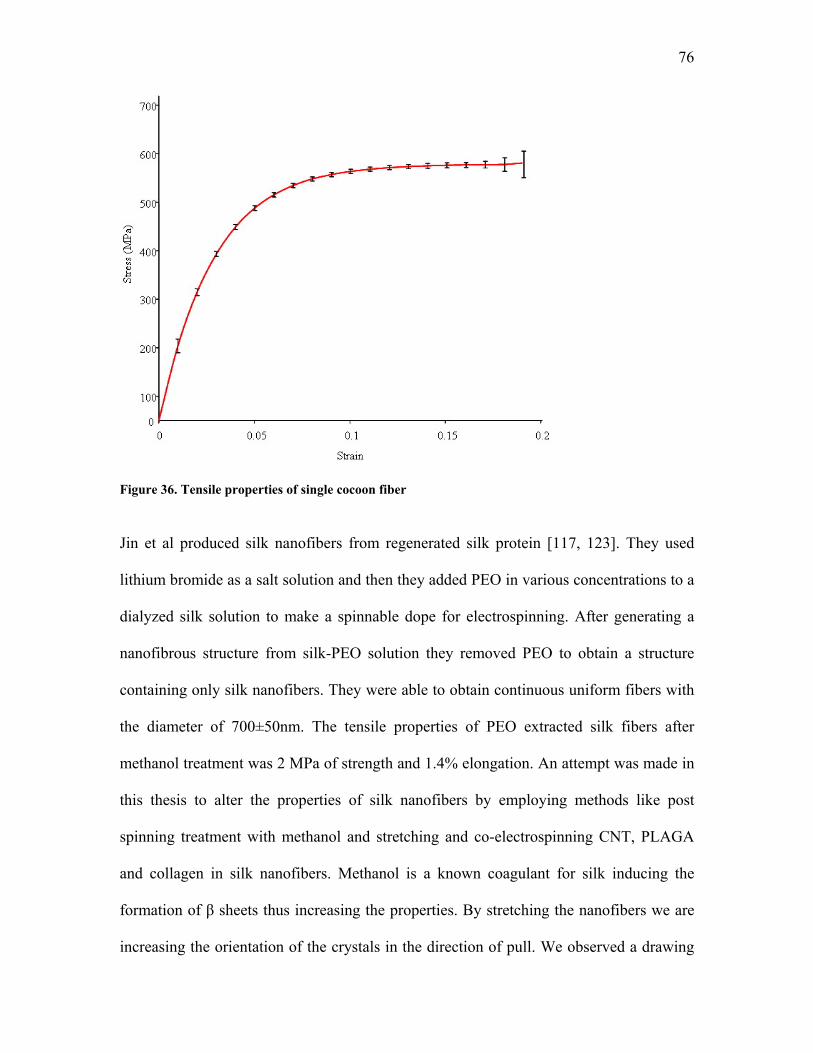
76
Figure 36. Tensile properties of single cocoon fiber
Jin et al produced silk nanofibers from regenerated silk protein [117, 123]. They used
lithium bromide as a salt solution and then they added PEO in various concentrations to a
dialyzed silk solution to make a spinnable dope for electrospinning. After generating a
nanofibrous structure from silk-PEO solution they removed PEO to obtain a structure
containing only silk nanofibers. They were able to obtain continuous uniform fibers with
the diameter of 700±50nm. The tensile properties of PEO extracted silk fibers after
methanol treatment was 2 MPa of strength and 1.4% elongation. An attempt was made in
this thesis to alter the properties of silk nanofibers by employing methods like post
spinning treatment with methanol and stretching and co-electrospinning CNT, PLAGA
and collagen in silk nanofibers. Methanol is a known coagulant for silk inducing the
formation of β sheets thus increasing the properties. By stretching the nanofibers we are
increasing the orientation of the crystals in the direction of pull. We observed a drawing
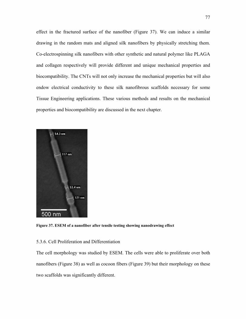
77
effect in the fractured surface of the nanofiber (Figure 37). We can induce a similar
drawing in the random mats and aligned silk nanofibers by physically stretching them.
Co-electrospinning silk nanofibers with other synthetic and natural polymer like PLAGA
and collagen respectively will provide different and unique mechanical properties and
biocompatibility. The CNTs will not only increase the mechanical properties but will also
endow electrical conductivity to these silk nanofibrous scaffolds necessary for some
Tissue Engineering applications. These various methods and results on the mechanical
properties and biocompatibility are discussed in the next chapter.
Figure 37. ESEM of a nanofiber after tensile testing showing nanodrawing effect
5.3.6. Cell Proliferation and Differentiation
The cell morphology was studied by ESEM. The cells were able to proliferate over both
nanofibers (Figure 38) as well as cocoon fibers (Figure 39) but their morphology on these
two scaffolds was significantly different.
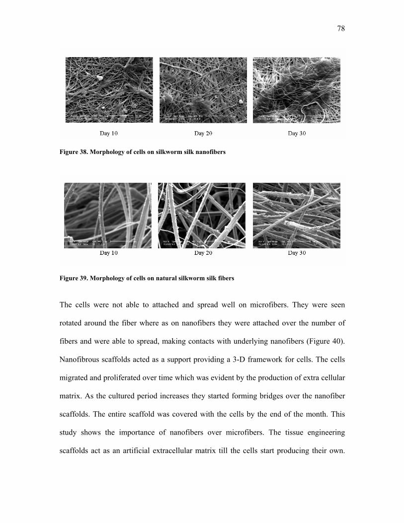
78
Figure 38. Morphology of cells on silkworm silk nanofibers
Figure 39. Morphology of cells on natural silkworm silk fibers
The cells were not able to attached and spread well on microfibers. They were seen
rotated around the fiber where as on nanofibers they were attached over the number of
fibers and were able to spread, making contacts with underlying nanofibers (Figure 40).
Nanofibrous scaffolds acted as a support providing a 3-D framework for cells. The cells
migrated and proliferated over time which was evident by the production of extra cellular
matrix. As the cultured period increases they started forming bridges over the nanofiber
scaffolds. The entire scaffold was covered with the cells by the end of the month. This
study shows the importance of nanofibers over microfibers. The tissue engineering
scaffolds act as an artificial extracellular matrix till the cells start producing their own.
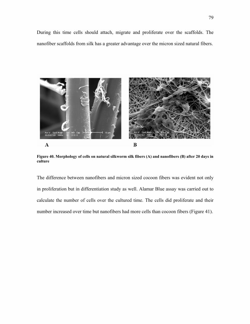
79
During this time cells should attach, migrate and proliferate over the scaffolds. The
nanofiber scaffolds from silk has a greater advantage over the micron sized natural fibers.
Figure 40. Morphology of cells on natural silkworm silk fibers (A) and nanofibers (B) after 20 days in culture
The difference between nanofibers and micron sized cocoon fibers was evident not only
in proliferation but in differentiation study as well. Alamar Blue assay was carried out to
calculate the number of cells over the cultured time. The cells did proliferate and their
number increased over time but nanofibers had more cells than cocoon fibers (Figure 41).
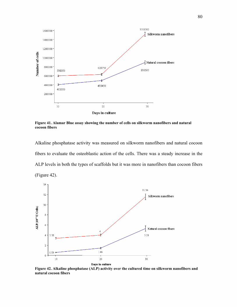
80
Figure 41. Alamar Blue assay showing the number of cells on silkworm nanofibers and natural cocoon fibers
Alkaline phosphatase activity was measured on silkworm nanofibers and natural cocoon
fibers to evaluate the osteoblastic action of the cells. There was a steady increase in the
ALP levels in both the types of scaffolds but it was more in nanofibers than cocoon fibers
(Figure 42).
Figure 42. Alkaline phosphatase (ALP) activity over the cultured time on silkworm nanofibers and natural cocoon fibers
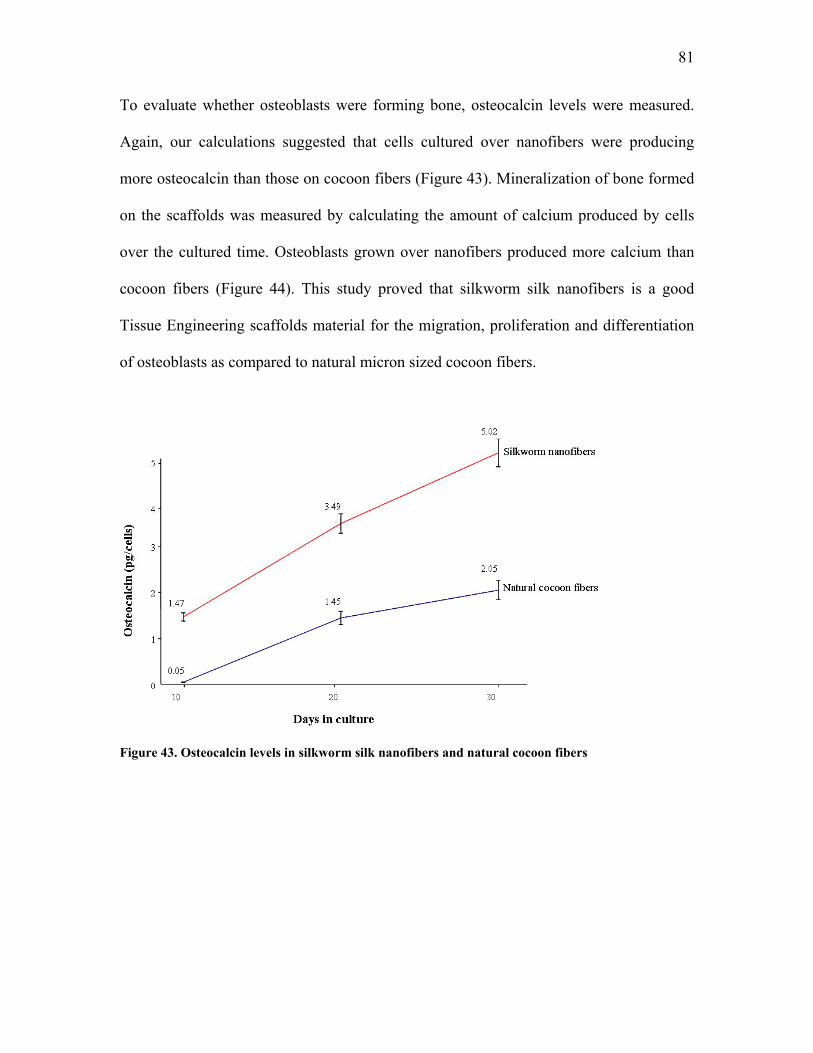
81
To evaluate whether osteoblasts were forming bone, osteocalcin levels were measured.
Again, our calculations suggested that cells cultured over nanofibers were producing
more osteocalcin than those on cocoon fibers (Figure 43). Mineralization of bone formed
on the scaffolds was measured by calculating the amount of calcium produced by cells
over the cultured time. Osteoblasts grown over nanofibers produced more calcium than
cocoon fibers (Figure 44). This study proved that silkworm silk nanofibers is a good
Tissue Engineering scaffolds material for the migration, proliferation and differentiation
of osteoblasts as compared to natural micron sized cocoon fibers.
Figure 43. Osteocalcin levels in silkworm silk nanofibers and natural cocoon fibers
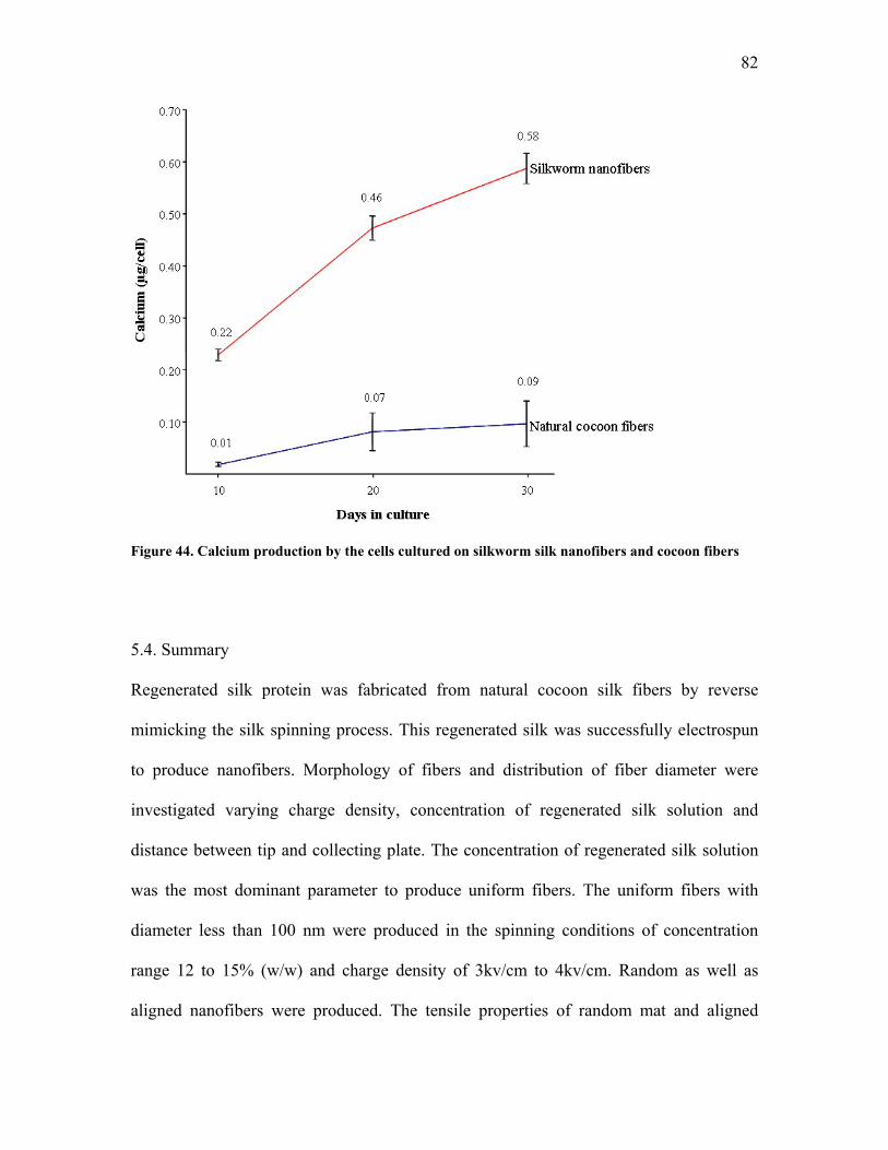
82
Figure 44. Calcium production by the cells cultured on silkworm silk nanofibers and cocoon fibers
5.4. Summary
Regenerated silk protein was fabricated from natural cocoon silk fibers by reverse
mimicking the silk spinning process. This regenerated silk was successfully electrospun
to produce nanofibers. Morphology of fibers and distribution of fiber diameter were
investigated varying charge density, concentration of regenerated silk solution and
distance between tip and collecting plate. The concentration of regenerated silk solution
was the most dominant parameter to produce uniform fibers. The uniform fibers with
diameter less than 100 nm were produced in the spinning conditions of concentration
range 12 to 15% (w/w) and charge density of 3kv/cm to 4kv/cm. Random as well as
aligned nanofibers were produced. The tensile properties of random mat and aligned
83
fibers were comparable to the other forms of regenerated silk produced by other
researchers. Cell-matrix interaction study using primary fetal bovine osteoblasts proved
that nanofibers allowed better proliferation and differentiation of osteoblasts as compared
to natural micron sized cocoon fibers. Alteration in the properties of silk nanofibers by
employing methods like post spinning treatment with methanol and stretching and co-
electrospinning CNT, PLAGA and collagen in silk nanofibers is described in next
chapter.
84
CHAPTER 6: MODIFICATION OF MECHANICAL PROPERTIES OF
SILKWORM SILK NANOFIBERS
6.1. Introduction
The nanofibers produced from the regenerated Bombyx mori silk are the ideal candidate
for Tissue Engineering scaffolds because of the advantage of having high surface area to
volume ratio. As described earlier, to fabricate a regenerated silk protein the natural
cocoon silk fibers are dissolved in a concentrated salt solution, then dialyzed to remove
salt and finally lyophilized to remove water. This regenerated silk is dissolved in an
appropriate solvent and electrospun to produce nanofibers. As suggested in Chapter 5 the
silk nanofibers random mat had a modulus of 140.67 ± 2.21 MPa, strength of 6.18 ± 0.3
MPa and elasticity of 5.78 ± 0.65 %. The aligned fibers had a modulus of 174.98 ± 2.86
MPa, strength of 7.75 ± 0.4 MPa and elasticity of 5.05 ± 0.45 %. These properties of
nanofibers from regenerated silk are an order of magnitude less than the natural cocoon
fibers. The regenerated silk is known to have lower properties than the natural cocoon
fibers [117, 122, 123] mainly because of the structural changes happening in the process
of regeneration. The silk produced by regeneration method has lower β sheets contents
resulting in a lower crystallinity and hence lower properties. An attempt was made in this
thesis to narrow the gap by altering the properties of silk nanofibers using post spinning
treatment and co-electrospinning method. Methanol is known to induce crystallization in
silk fibroin by forming β sheets [33, 43]. It is well known in Textile fibers that physical
annealing helps in the orientation of the crystals in the direction of pull. We hypothesize
85
that post spinning treatment of the random as well as aligned silk nanofibers with
methanol along with stretching will improve the mechanical properties of nanofibers.
Another method for improving the properties is dispersing the particles in the fibers. The
elongation balance theory [93, 94] suggest that combining materials with similar
elongation at break provide the most effective means of transferring tensile properties.
On the basis of this theory, silk (15-20% elongation at break) and CNT (6-30%
elongation at break) are the most compatible material systems. It has been demonstrated
by Ko et al. that co-electrospinning provides an excellent method for aligning CNT in
polymer fibril matrix [89]. Mechanical properties of nanocomposites prepared by co-
electrospinning 1 to 5 % CNT (w/w) in a polyacrylonitrile nanofiber matrix suggested a
4 to 5 fold increase in the properties [95]. We hypothesize that CNTs will improve the
mechanical properties as well as provide electrical conductivity to the silk nanofibrous
scaffolds. Preparing the blends of silk with other synthetic and natural polymer like
PLAGA and collagen was also employed in this study. This can not only modify the
properties but also improve the biocompatibility silk nanofibrous scaffolds. The
regenerated silk was prepared as describes in section 5.2.1 of Chapter 5. Briefly, the
degummed cocoon fibers were dissolved in aqueous CaCl2, then dialyzed against
deionized water and finally lyophilized to obtain a regenerated silk fibroin sponge. For
post spinning treatment regenerated silk was electrospun in formic acid at 15%
concentration with charge density of 3 kV/cm and distance of 10cm. Both random and
aligned silk fibers were obtained. The aligned fibers were obtained using secondary
collection plate technique described earlier in section 5.2.2. The post spinning treatment
with methanol and stretching was carried out on these fibers. The spinning dope for co-
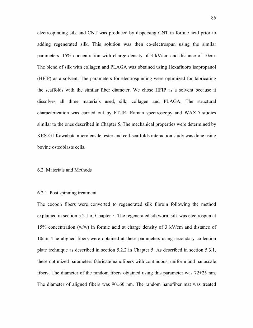
86
electrospinning silk and CNT was produced by dispersing CNT in formic acid prior to
adding regenerated silk. This solution was then co-electrospun using the similar
parameters, 15% concentration with charge density of 3 kV/cm and distance of 10cm.
The blend of silk with collagen and PLAGA was obtained using Hexafluoro isopropanol
(HFIP) as a solvent. The parameters for electrospinning were optimized for fabricating
the scaffolds with the similar fiber diameter. We chose HFIP as a solvent because it
dissolves all three materials used, silk, collagen and PLAGA. The structural
characterization was carried out by FT-IR, Raman spectroscopy and WAXD studies
similar to the ones described in Chapter 5. The mechanical properties were determined by
KES-G1 Kawabata microtensile tester and cell-scaffolds interaction study was done using
bovine osteoblasts cells.
6.2. Materials and Methods
6.2.1. Post spinning treatment
The cocoon fibers were converted to regenerated silk fibroin following the method
explained in section 5.2.1 of Chapter 5. The regenerated silkworm silk was electrospun at
15% concentration (w/w) in formic acid at charge density of 3 kV/cm and distance of
10cm. The aligned fibers were obtained at these parameters using secondary collection
plate technique as described in section 5.2.2 in Chapter 5. As described in section 5.3.1,
these optimized parameters fabricate nanofibers with continuous, uniform and nanoscale
fibers. The diameter of the random fibers obtained using this parameter was 72±25 nm.
The diameter of aligned fibers was 90±60 nm. The random nanofiber mat was treated
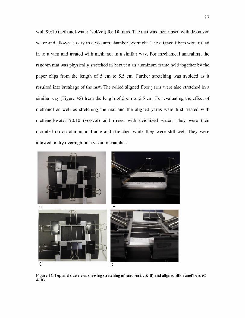
87
with 90:10 methanol-water (vol/vol) for 10 mins. The mat was then rinsed with deionized
water and allowed to dry in a vacuum chamber overnight. The aligned fibers were rolled
in to a yarn and treated with methanol in a similar way. For mechanical annealing, the
random mat was physically stretched in between an aluminum frame held together by the
paper clips from the length of 5 cm to 5.5 cm. Further stretching was avoided as it
resulted into breakage of the mat. The rolled aligned fiber yarns were also stretched in a
similar way (Figure 45) from the length of 5 cm to 5.5 cm. For evaluating the effect of
methanol as well as stretching the mat and the aligned yarns were first treated with
methanol-water 90:10 (vol/vol) and rinsed with deionized water. They were then
mounted on an aluminum frame and stretched while they were still wet. They were
allowed to dry overnight in a vacuum chamber.
Figure 45. Top and side views showing stretching of random (A & B) and aligned silk nanofibers (C & D).
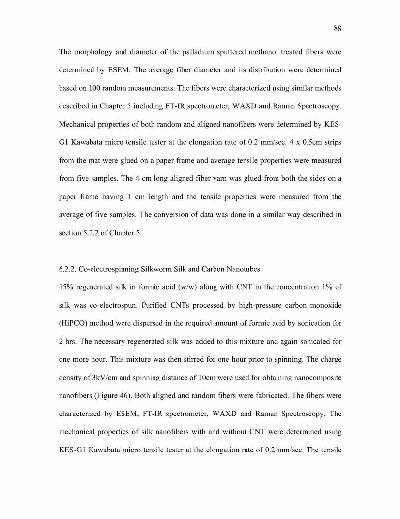
88
The morphology and diameter of the palladium sputtered methanol treated fibers were
determined by ESEM. The average fiber diameter and its distribution were determined
based on 100 random measurements. The fibers were characterized using similar methods
described in Chapter 5 including FT-IR spectrometer, WAXD and Raman Spectroscopy.
Mechanical properties of both random and aligned nanofibers were determined by KES-
G1 Kawabata micro tensile tester at the elongation rate of 0.2 mm/sec. 4 x 0.5cm strips
from the mat were glued on a paper frame and average tensile properties were measured
from five samples. The 4 cm long aligned fiber yarn was glued from both the sides on a
paper frame having 1 cm length and the tensile properties were measured from the
average of five samples. The conversion of data was done in a similar way described in
section 5.2.2 of Chapter 5.
6.2.2. Co-electrospinning Silkworm Silk and Carbon Nanotubes
15% regenerated silk in formic acid (w/w) along with CNT in the concentration 1% of
silk was co-electrospun. Purified CNTs processed by high-pressure carbon monoxide
(HiPCO) method were dispersed in the required amount of formic acid by sonication for
2 hrs. The necessary regenerated silk was added to this mixture and again sonicated for
one more hour. This mixture was then stirred for one hour prior to spinning. The charge
density of 3kV/cm and spinning distance of 10cm were used for obtaining nanocomposite
nanofibers (Figure 46). Both aligned and random fibers were fabricated. The fibers were
characterized by ESEM, FT-IR spectrometer, WAXD and Raman Spectroscopy. The
mechanical properties of silk nanofibers with and without CNT were determined using
KES-G1 Kawabata micro tensile tester at the elongation rate of 0.2 mm/sec. The tensile
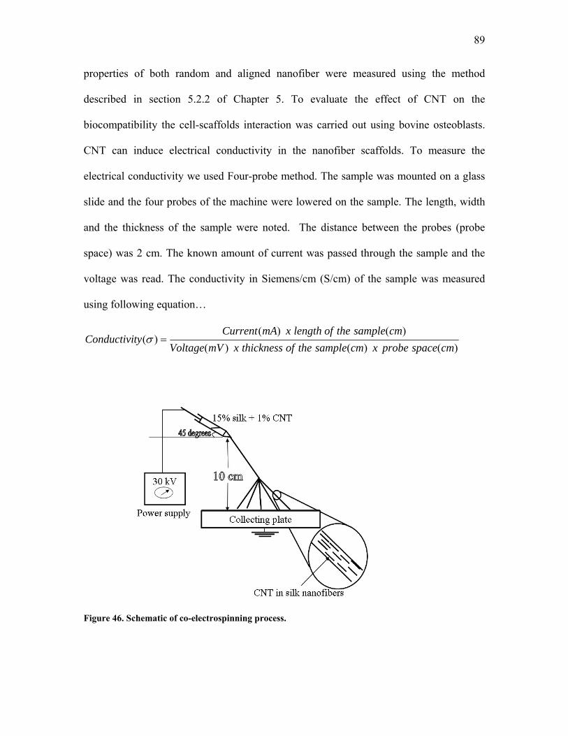
89
properties of both random and aligned nanofiber were measured using the method
described in section 5.2.2 of Chapter 5. To evaluate the effect of CNT on the
biocompatibility the cell-scaffolds interaction was carried out using bovine osteoblasts.
CNT can induce electrical conductivity in the nanofiber scaffolds. To measure the
electrical conductivity we used Four-probe method. The sample was mounted on a glass
slide and the four probes of the machine were lowered on the sample. The length, width
and the thickness of the sample were noted. The distance between the probes (probe
space) was 2 cm. The known amount of current was passed through the sample and the
voltage was read. The conductivity in Siemens/cm (S/cm) of the sample was measured
using following equation…
)()()()()(
)(cmspaceprobexcmsampletheofthicknessxmVVoltage
cmsampletheoflengthxmACurrenttyConductivi =σ
Figure 46. Schematic of co-electrospinning process.
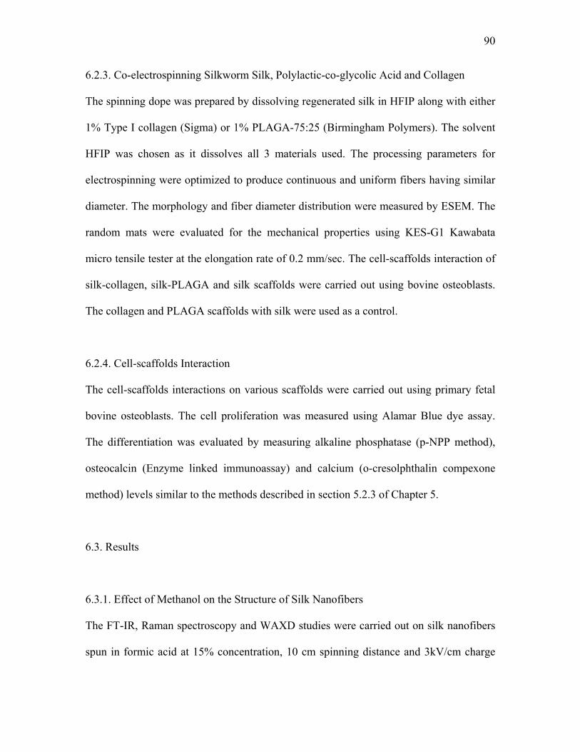
90
6.2.3. Co-electrospinning Silkworm Silk, Polylactic-co-glycolic Acid and Collagen
The spinning dope was prepared by dissolving regenerated silk in HFIP along with either
1% Type I collagen (Sigma) or 1% PLAGA-75:25 (Birmingham Polymers). The solvent
HFIP was chosen as it dissolves all 3 materials used. The processing parameters for
electrospinning were optimized to produce continuous and uniform fibers having similar
diameter. The morphology and fiber diameter distribution were measured by ESEM. The
random mats were evaluated for the mechanical properties using KES-G1 Kawabata
micro tensile tester at the elongation rate of 0.2 mm/sec. The cell-scaffolds interaction of
silk-collagen, silk-PLAGA and silk scaffolds were carried out using bovine osteoblasts.
The collagen and PLAGA scaffolds with silk were used as a control.
6.2.4. Cell-scaffolds Interaction
The cell-scaffolds interactions on various scaffolds were carried out using primary fetal
bovine osteoblasts. The cell proliferation was measured using Alamar Blue dye assay.
The differentiation was evaluated by measuring alkaline phosphatase (p-NPP method),
osteocalcin (Enzyme linked immunoassay) and calcium (o-cresolphthalin compexone
method) levels similar to the methods described in section 5.2.3 of Chapter 5.
6.3. Results
6.3.1. Effect of Methanol on the Structure of Silk Nanofibers
The FT-IR, Raman spectroscopy and WAXD studies were carried out on silk nanofibers
spun in formic acid at 15% concentration, 10 cm spinning distance and 3kV/cm charge
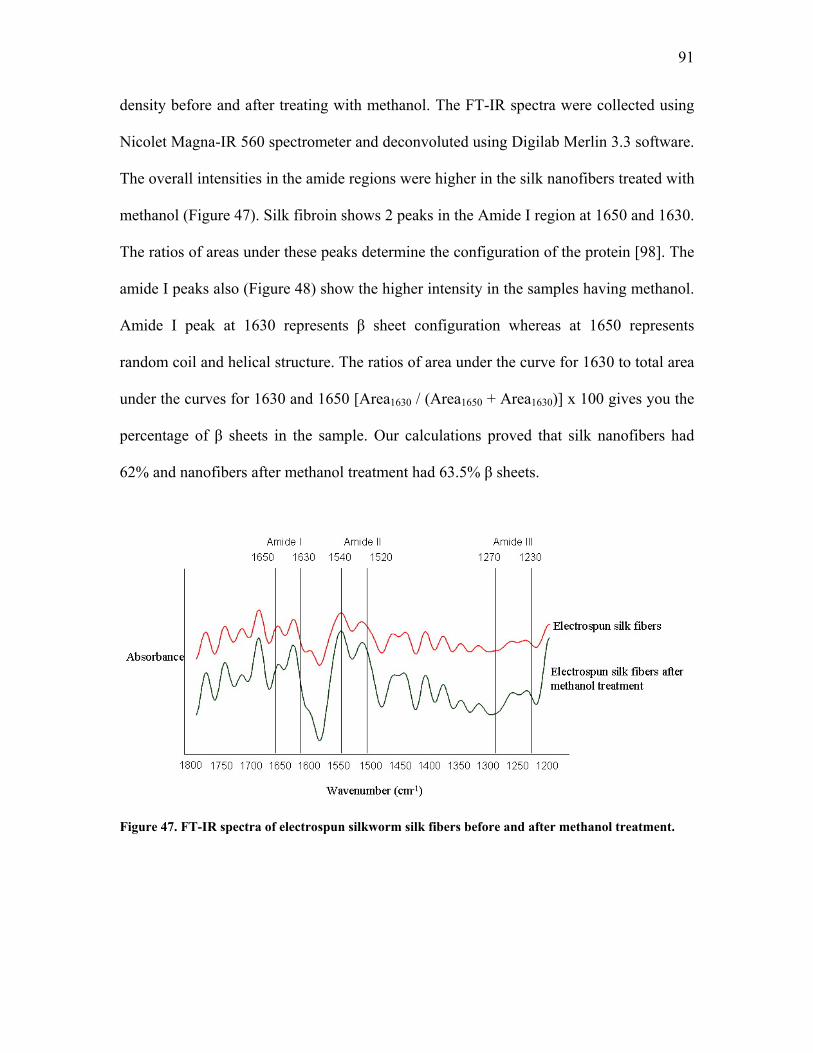
91
density before and after treating with methanol. The FT-IR spectra were collected using
Nicolet Magna-IR 560 spectrometer and deconvoluted using Digilab Merlin 3.3 software.
The overall intensities in the amide regions were higher in the silk nanofibers treated with
methanol (Figure 47). Silk fibroin shows 2 peaks in the Amide I region at 1650 and 1630.
The ratios of areas under these peaks determine the configuration of the protein [98]. The
amide I peaks also (Figure 48) show the higher intensity in the samples having methanol.
Amide I peak at 1630 represents β sheet configuration whereas at 1650 represents
random coil and helical structure. The ratios of area under the curve for 1630 to total area
under the curves for 1630 and 1650 [Area1630 / (Area1650 + Area1630)] x 100 gives you the
percentage of β sheets in the sample. Our calculations proved that silk nanofibers had
62% and nanofibers after methanol treatment had 63.5% β sheets.
Figure 47. FT-IR spectra of electrospun silkworm silk fibers before and after methanol treatment.
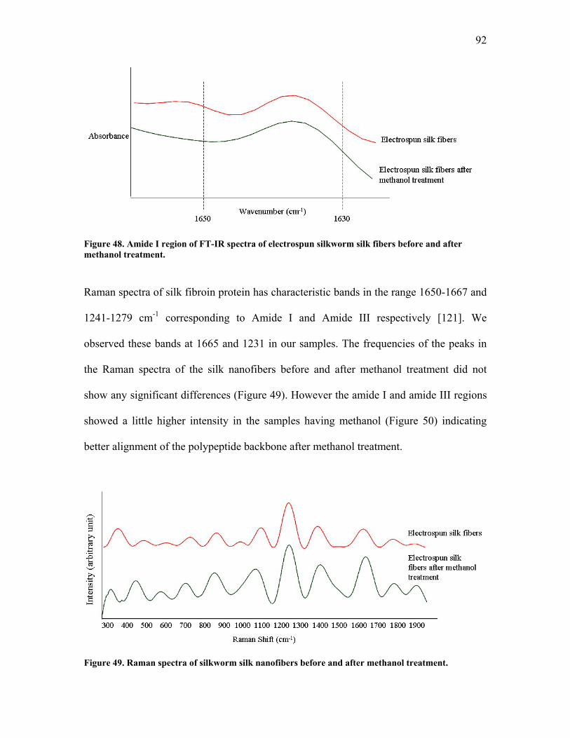
92
Figure 48. Amide I region of FT-IR spectra of electrospun silkworm silk fibers before and after methanol treatment.
Raman spectra of silk fibroin protein has characteristic bands in the range 1650-1667 and
1241-1279 cm-1 corresponding to Amide I and Amide III respectively [121]. We
observed these bands at 1665 and 1231 in our samples. The frequencies of the peaks in
the Raman spectra of the silk nanofibers before and after methanol treatment did not
show any significant differences (Figure 49). However the amide I and amide III regions
showed a little higher intensity in the samples having methanol (Figure 50) indicating
better alignment of the polypeptide backbone after methanol treatment.
Figure 49. Raman spectra of silkworm silk nanofibers before and after methanol treatment.
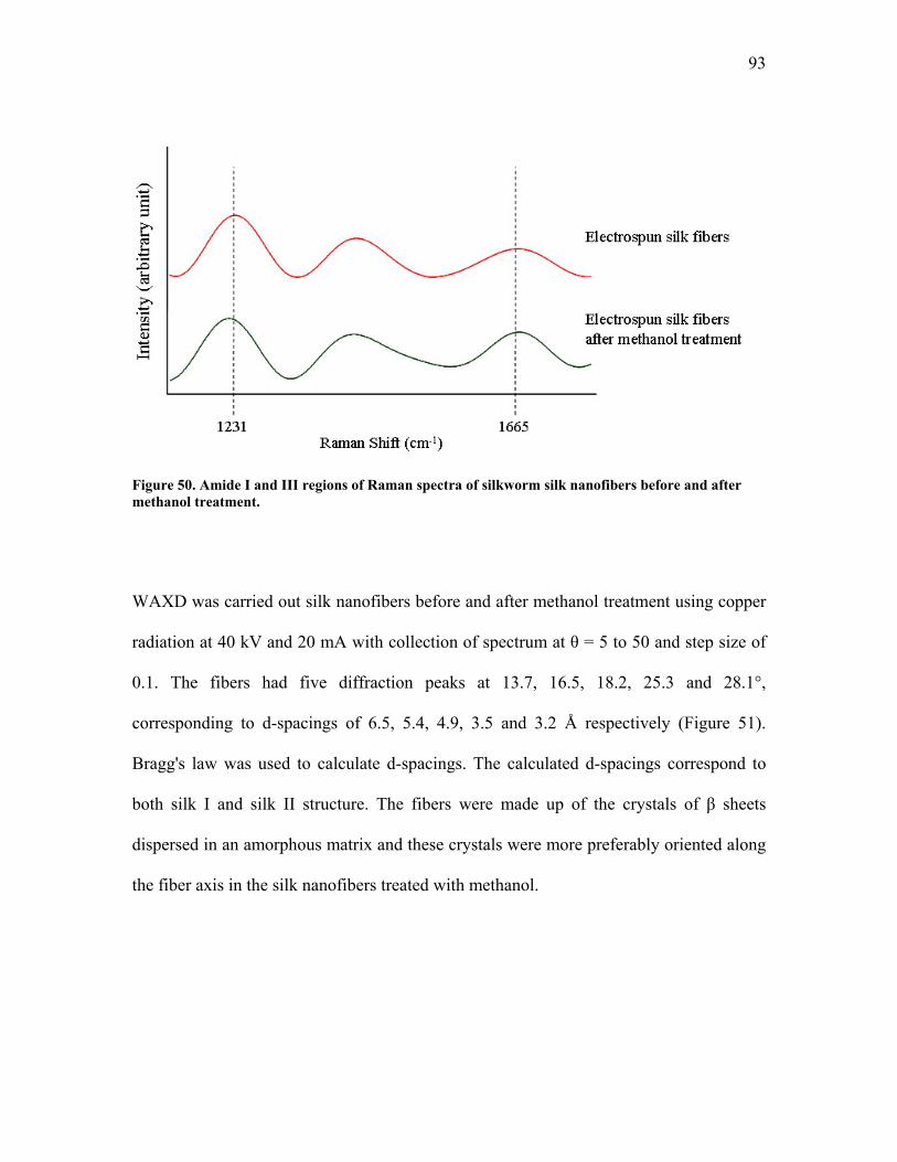
93
Figure 50. Amide I and III regions of Raman spectra of silkworm silk nanofibers before and after methanol treatment.
WAXD was carried out silk nanofibers before and after methanol treatment using copper
radiation at 40 kV and 20 mA with collection of spectrum at θ = 5 to 50 and step size of
0.1. The fibers had five diffraction peaks at 13.7, 16.5, 18.2, 25.3 and 28.1°,
corresponding to d-spacings of 6.5, 5.4, 4.9, 3.5 and 3.2 Å respectively (Figure 51).
Bragg's law was used to calculate d-spacings. The calculated d-spacings correspond to
both silk I and silk II structure. The fibers were made up of the crystals of β sheets
dispersed in an amorphous matrix and these crystals were more preferably oriented along
the fiber axis in the silk nanofibers treated with methanol.
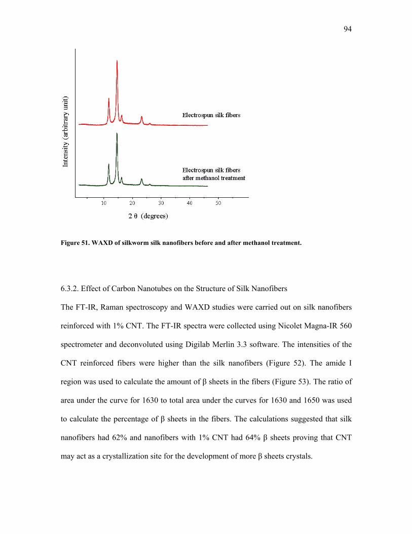
94
Figure 51. WAXD of silkworm silk nanofibers before and after methanol treatment.
6.3.2. Effect of Carbon Nanotubes on the Structure of Silk Nanofibers
The FT-IR, Raman spectroscopy and WAXD studies were carried out on silk nanofibers
reinforced with 1% CNT. The FT-IR spectra were collected using Nicolet Magna-IR 560
spectrometer and deconvoluted using Digilab Merlin 3.3 software. The intensities of the
CNT reinforced fibers were higher than the silk nanofibers (Figure 52). The amide I
region was used to calculate the amount of β sheets in the fibers (Figure 53). The ratio of
area under the curve for 1630 to total area under the curves for 1630 and 1650 was used
to calculate the percentage of β sheets in the fibers. The calculations suggested that silk
nanofibers had 62% and nanofibers with 1% CNT had 64% β sheets proving that CNT
may act as a crystallization site for the development of more β sheets crystals.
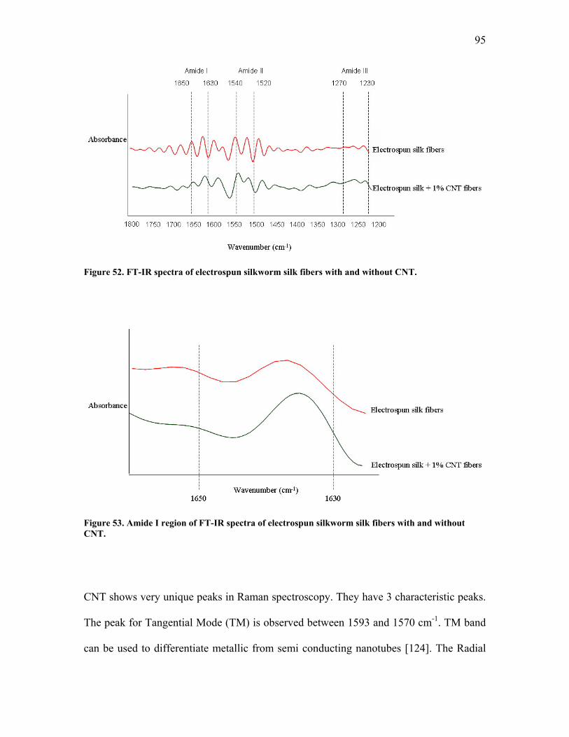
95
Figure 52. FT-IR spectra of electrospun silkworm silk fibers with and without CNT.
Figure 53. Amide I region of FT-IR spectra of electrospun silkworm silk fibers with and without CNT.
CNT shows very unique peaks in Raman spectroscopy. They have 3 characteristic peaks.
The peak for Tangential Mode (TM) is observed between 1593 and 1570 cm-1. TM band
can be used to differentiate metallic from semi conducting nanotubes [124]. The Radial
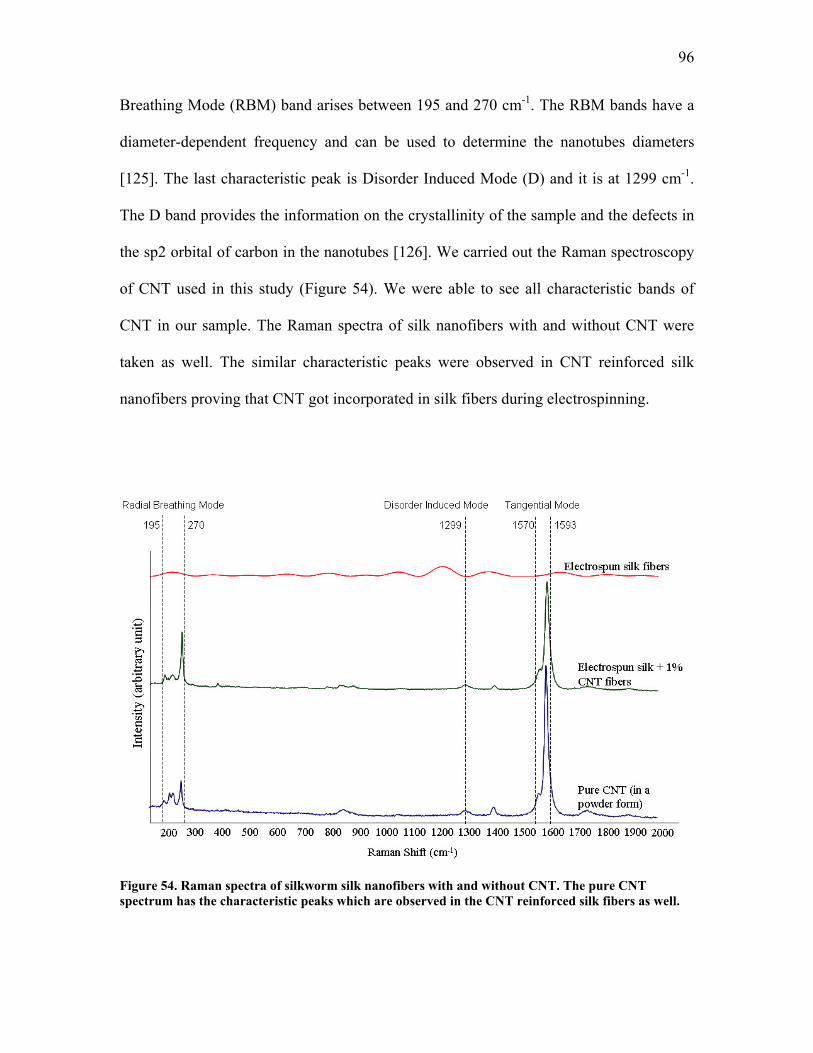
96
Breathing Mode (RBM) band arises between 195 and 270 cm-1. The RBM bands have a
diameter-dependent frequency and can be used to determine the nanotubes diameters
[125]. The last characteristic peak is Disorder Induced Mode (D) and it is at 1299 cm-1.
The D band provides the information on the crystallinity of the sample and the defects in
the sp2 orbital of carbon in the nanotubes [126]. We carried out the Raman spectroscopy
of CNT used in this study (Figure 54). We were able to see all characteristic bands of
CNT in our sample. The Raman spectra of silk nanofibers with and without CNT were
taken as well. The similar characteristic peaks were observed in CNT reinforced silk
nanofibers proving that CNT got incorporated in silk fibers during electrospinning.
Figure 54. Raman spectra of silkworm silk nanofibers with and without CNT. The pure CNT spectrum has the characteristic peaks which are observed in the CNT reinforced silk fibers as well.
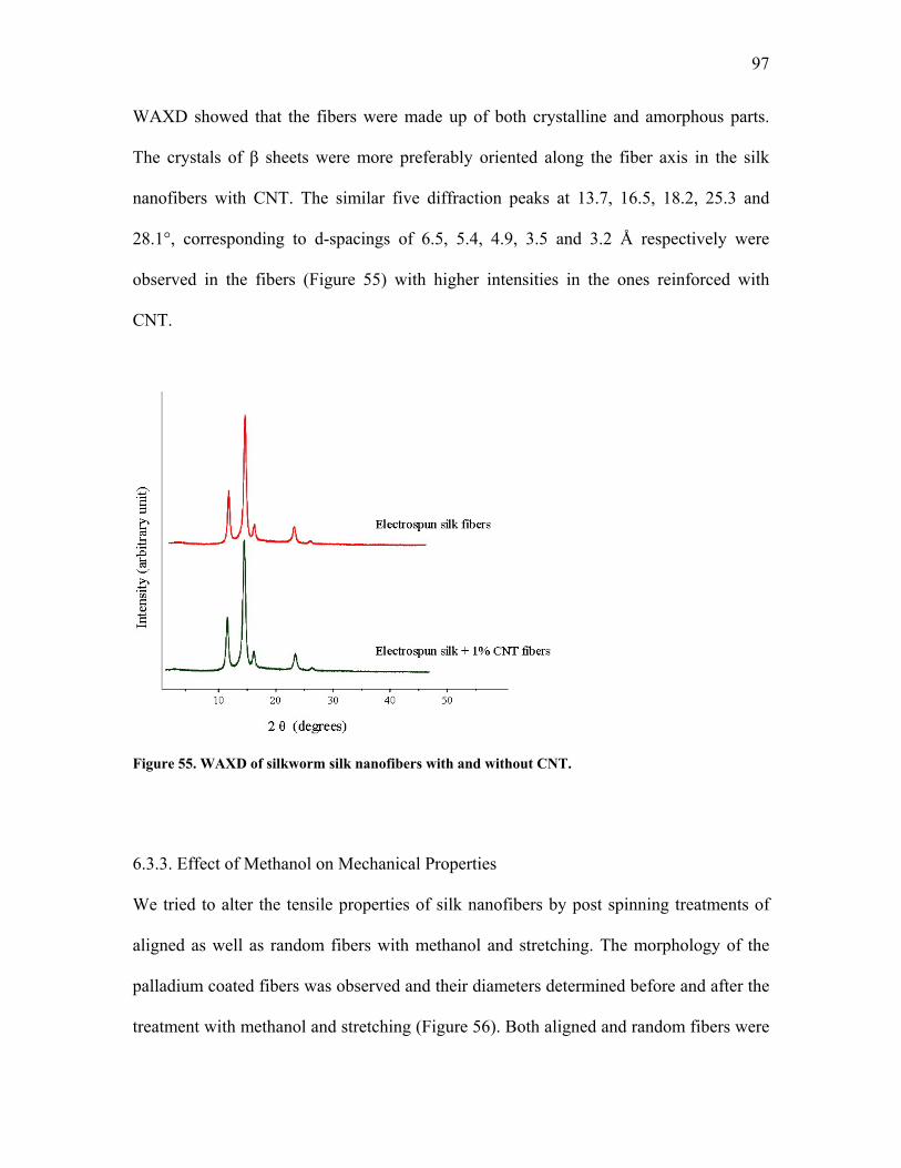
97
WAXD showed that the fibers were made up of both crystalline and amorphous parts.
The crystals of β sheets were more preferably oriented along the fiber axis in the silk
nanofibers with CNT. The similar five diffraction peaks at 13.7, 16.5, 18.2, 25.3 and
28.1°, corresponding to d-spacings of 6.5, 5.4, 4.9, 3.5 and 3.2 Å respectively were
observed in the fibers (Figure 55) with higher intensities in the ones reinforced with
CNT.
Figure 55. WAXD of silkworm silk nanofibers with and without CNT.
6.3.3. Effect of Methanol on Mechanical Properties
We tried to alter the tensile properties of silk nanofibers by post spinning treatments of
aligned as well as random fibers with methanol and stretching. The morphology of the
palladium coated fibers was observed and their diameters determined before and after the
treatment with methanol and stretching (Figure 56). Both aligned and random fibers were
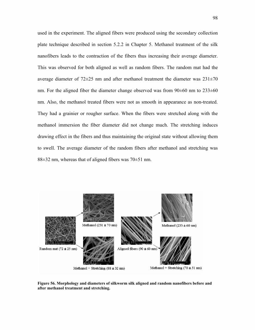
98
used in the experiment. The aligned fibers were produced using the secondary collection
plate technique described in section 5.2.2 in Chapter 5. Methanol treatment of the silk
nanofibers leads to the contraction of the fibers thus increasing their average diameter.
This was observed for both aligned as well as random fibers. The random mat had the
average diameter of 72±25 nm and after methanol treatment the diameter was 231±70
nm. For the aligned fiber the diameter change observed was from 90±60 nm to 233±60
nm. Also, the methanol treated fibers were not as smooth in appearance as non-treated.
They had a grainier or rougher surface. When the fibers were stretched along with the
methanol immersion the fiber diameter did not change much. The stretching induces
drawing effect in the fibers and thus maintaining the original state without allowing them
to swell. The average diameter of the random fibers after methanol and stretching was
88±32 nm, whereas that of aligned fibers was 70±51 nm.
Figure 56. Morphology and diameters of silkworm silk aligned and random nanofibers before and after methanol treatment and stretching.
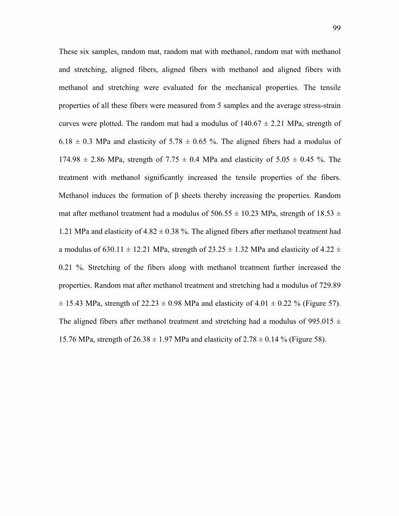
99
These six samples, random mat, random mat with methanol, random mat with methanol
and stretching, aligned fibers, aligned fibers with methanol and aligned fibers with
methanol and stretching were evaluated for the mechanical properties. The tensile
properties of all these fibers were measured from 5 samples and the average stress-strain
curves were plotted. The random mat had a modulus of 140.67 ± 2.21 MPa, strength of
6.18 ± 0.3 MPa and elasticity of 5.78 ± 0.65 %. The aligned fibers had a modulus of
174.98 ± 2.86 MPa, strength of 7.75 ± 0.4 MPa and elasticity of 5.05 ± 0.45 %. The
treatment with methanol significantly increased the tensile properties of the fibers.
Methanol induces the formation of β sheets thereby increasing the properties. Random
mat after methanol treatment had a modulus of 506.55 ± 10.23 MPa, strength of 18.53 ±
1.21 MPa and elasticity of 4.82 ± 0.38 %. The aligned fibers after methanol treatment had
a modulus of 630.11 ± 12.21 MPa, strength of 23.25 ± 1.32 MPa and elasticity of 4.22 ±
0.21 %. Stretching of the fibers along with methanol treatment further increased the
properties. Random mat after methanol treatment and stretching had a modulus of 729.89
± 15.43 MPa, strength of 22.23 ± 0.98 MPa and elasticity of 4.01 ± 0.22 % (Figure 57).
The aligned fibers after methanol treatment and stretching had a modulus of 995.015 ±
15.76 MPa, strength of 26.38 ± 1.97 MPa and elasticity of 2.78 ± 0.14 % (Figure 58).
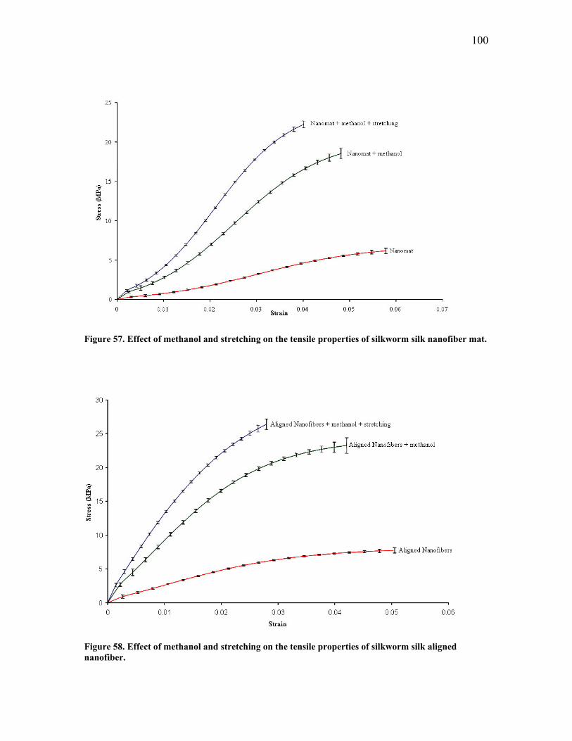
100
Figure 57. Effect of methanol and stretching on the tensile properties of silkworm silk nanofiber mat.
Figure 58. Effect of methanol and stretching on the tensile properties of silkworm silk aligned nanofiber.
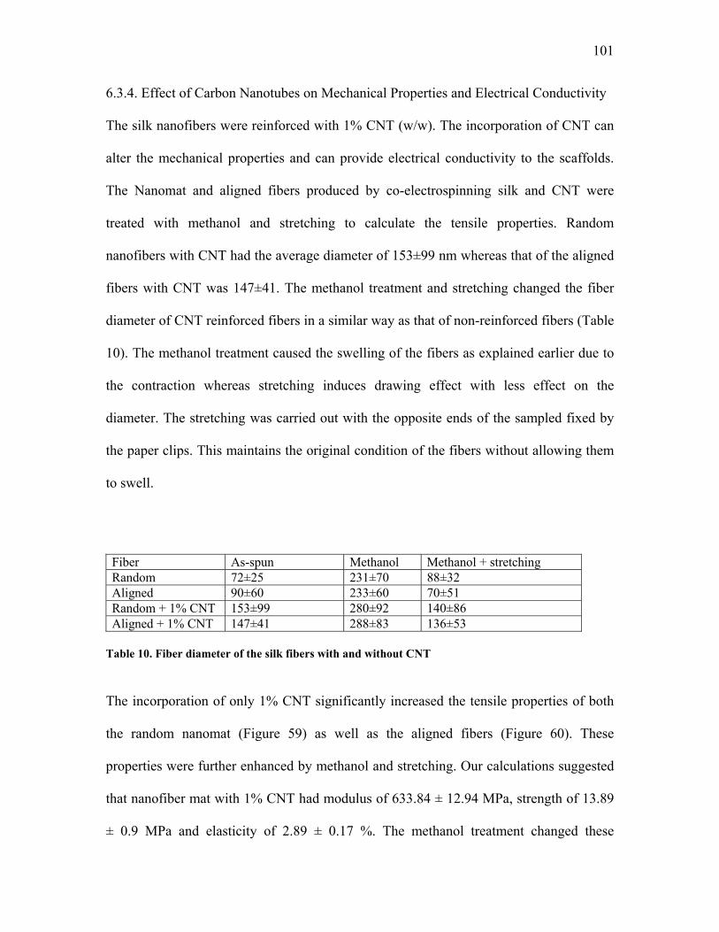
101
6.3.4. Effect of Carbon Nanotubes on Mechanical Properties and Electrical Conductivity
The silk nanofibers were reinforced with 1% CNT (w/w). The incorporation of CNT can
alter the mechanical properties and can provide electrical conductivity to the scaffolds.
The Nanomat and aligned fibers produced by co-electrospinning silk and CNT were
treated with methanol and stretching to calculate the tensile properties. Random
nanofibers with CNT had the average diameter of 153±99 nm whereas that of the aligned
fibers with CNT was 147±41. The methanol treatment and stretching changed the fiber
diameter of CNT reinforced fibers in a similar way as that of non-reinforced fibers (Table
10). The methanol treatment caused the swelling of the fibers as explained earlier due to
the contraction whereas stretching induces drawing effect with less effect on the
diameter. The stretching was carried out with the opposite ends of the sampled fixed by
the paper clips. This maintains the original condition of the fibers without allowing them
to swell.
Fiber As-spun Methanol Methanol + stretching Random 72±25 231±70 88±32 Aligned 90±60 233±60 70±51 Random + 1% CNT 153±99 280±92 140±86 Aligned + 1% CNT 147±41 288±83 136±53
Table 10. Fiber diameter of the silk fibers with and without CNT
The incorporation of only 1% CNT significantly increased the tensile properties of both
the random nanomat (Figure 59) as well as the aligned fibers (Figure 60). These
properties were further enhanced by methanol and stretching. Our calculations suggested
that nanofiber mat with 1% CNT had modulus of 633.84 ± 12.94 MPa, strength of 13.89
± 0.9 MPa and elasticity of 2.89 ± 0.17 %. The methanol treatment changed these
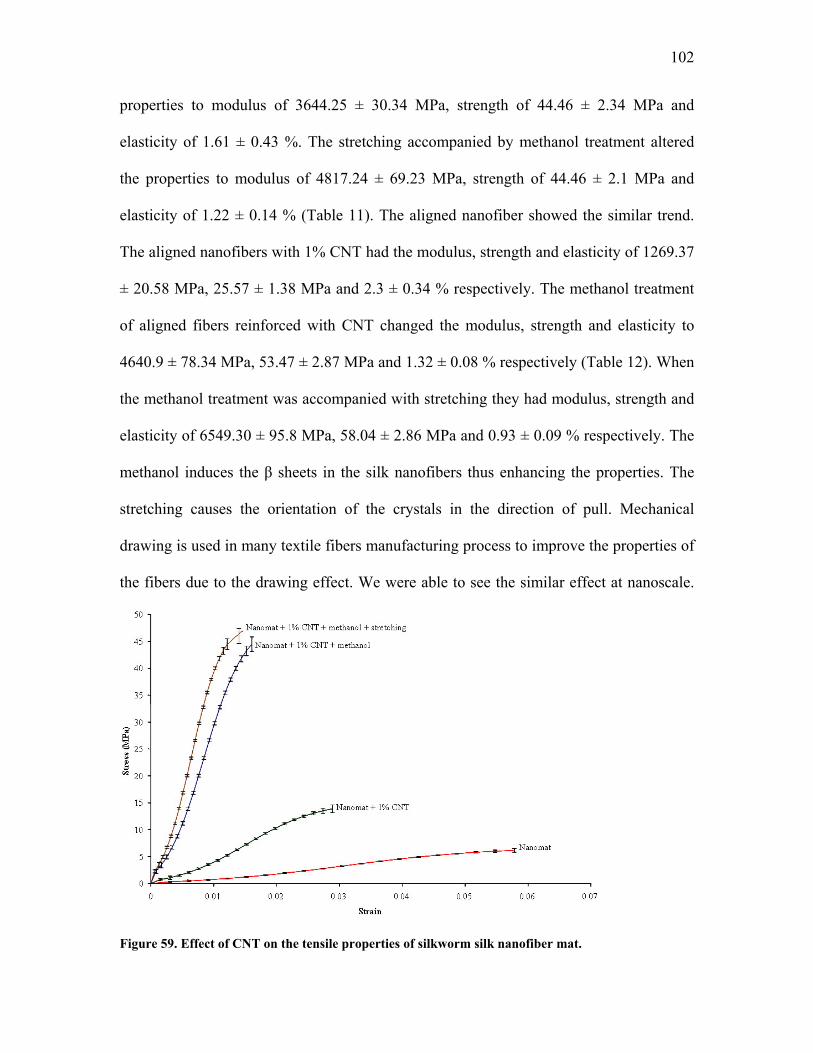
102
properties to modulus of 3644.25 ± 30.34 MPa, strength of 44.46 ± 2.34 MPa and
elasticity of 1.61 ± 0.43 %. The stretching accompanied by methanol treatment altered
the properties to modulus of 4817.24 ± 69.23 MPa, strength of 44.46 ± 2.1 MPa and
elasticity of 1.22 ± 0.14 % (Table 11). The aligned nanofiber showed the similar trend.
The aligned nanofibers with 1% CNT had the modulus, strength and elasticity of 1269.37
± 20.58 MPa, 25.57 ± 1.38 MPa and 2.3 ± 0.34 % respectively. The methanol treatment
of aligned fibers reinforced with CNT changed the modulus, strength and elasticity to
4640.9 ± 78.34 MPa, 53.47 ± 2.87 MPa and 1.32 ± 0.08 % respectively (Table 12). When
the methanol treatment was accompanied with stretching they had modulus, strength and
elasticity of 6549.30 ± 95.8 MPa, 58.04 ± 2.86 MPa and 0.93 ± 0.09 % respectively. The
methanol induces the β sheets in the silk nanofibers thus enhancing the properties. The
stretching causes the orientation of the crystals in the direction of pull. Mechanical
drawing is used in many textile fibers manufacturing process to improve the properties of
the fibers due to the drawing effect. We were able to see the similar effect at nanoscale.
Figure 59. Effect of CNT on the tensile properties of silkworm silk nanofiber mat.
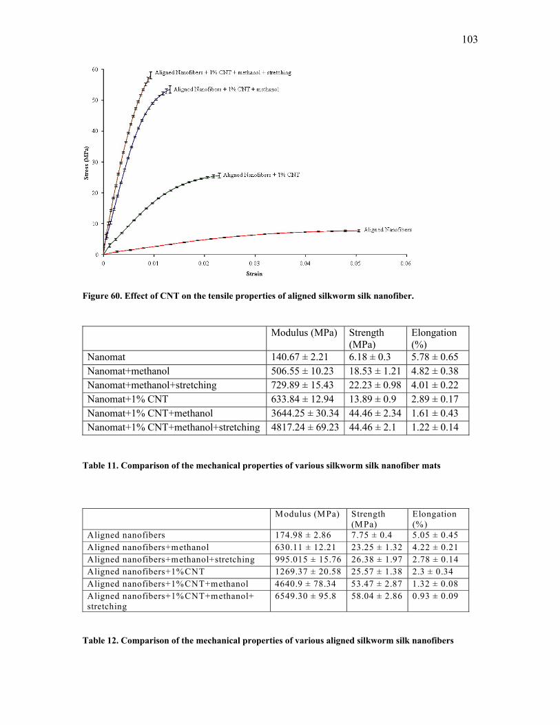
103
Figure 60. Effect of CNT on the tensile properties of aligned silkworm silk nanofiber. Modulus (MPa) Strength
(MPa) Elongation (%)
Nanomat 140.67 ± 2.21 6.18 ± 0.3 5.78 ± 0.65 Nanomat+methanol 506.55 ± 10.23 18.53 ± 1.21 4.82 ± 0.38 Nanomat+methanol+stretching 729.89 ± 15.43 22.23 ± 0.98 4.01 ± 0.22 Nanomat+1% CNT 633.84 ± 12.94 13.89 ± 0.9 2.89 ± 0.17 Nanomat+1% CNT+methanol 3644.25 ± 30.34 44.46 ± 2.34 1.61 ± 0.43 Nanomat+1% CNT+methanol+stretching 4817.24 ± 69.23 44.46 ± 2.1 1.22 ± 0.14
Table 11. Comparison of the mechanical properties of various silkworm silk nanofiber mats
Modulus (MPa) Strength (MPa)
Elongation (%)
Aligned nanofibers 174.98 ± 2.86 7.75 ± 0.4 5.05 ± 0.45 Aligned nanofibers+methanol 630.11 ± 12.21 23.25 ± 1.32 4.22 ± 0.21 Aligned nanofibers+methanol+stretching 995.015 ± 15.76 26.38 ± 1.97 2.78 ± 0.14 Aligned nanofibers+1%CNT 1269.37 ± 20.58 25.57 ± 1.38 2.3 ± 0.34 Aligned nanofibers+1%CNT+methanol 4640.9 ± 78.34 53.47 ± 2.87 1.32 ± 0.08 Aligned nanofibers+1%CNT+methanol+ stretching
6549.30 ± 95.8 58.04 ± 2.86 0.93 ± 0.09
Table 12. Comparison of the mechanical properties of various aligned silkworm silk nanofibers
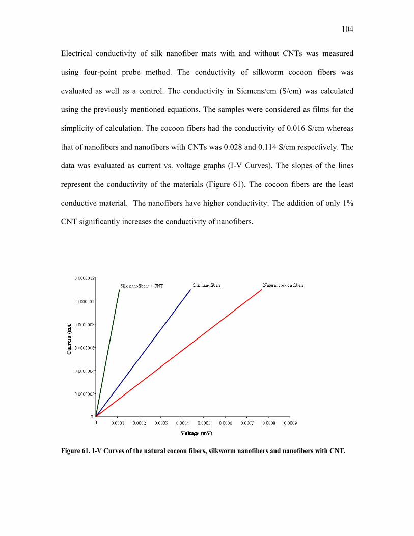
104
Electrical conductivity of silk nanofiber mats with and without CNTs was measured
using four-point probe method. The conductivity of silkworm cocoon fibers was
evaluated as well as a control. The conductivity in Siemens/cm (S/cm) was calculated
using the previously mentioned equations. The samples were considered as films for the
simplicity of calculation. The cocoon fibers had the conductivity of 0.016 S/cm whereas
that of nanofibers and nanofibers with CNTs was 0.028 and 0.114 S/cm respectively. The
data was evaluated as current vs. voltage graphs (I-V Curves). The slopes of the lines
represent the conductivity of the materials (Figure 61). The cocoon fibers are the least
conductive material. The nanofibers have higher conductivity. The addition of only 1%
CNT significantly increases the conductivity of nanofibers.
Figure 61. I-V Curves of the natural cocoon fibers, silkworm nanofibers and nanofibers with CNT.
105
6.3.5. Effect of Collagen and Polylactic-co-glycolic Acid on Mechanical Properties
Collagen is the natural protein abundantly present in the extra cellular matrix of many
tissues in our body. An attempt was made to electrospin a nonwoven mat consisting of
regenerated silk and Type I collagen. 1% (w/w) collagen was dissolved along with silk in
HFIP to make a spinning dope solution. PLAGA in the ratio of 75:25 was also
electrospun with silk. PLAGA is a synthetic polymer used in various biomedical
applications including Tissue Engineering. Again, 1% (w/w) PLAGA was dissolved with
regenerated silk in HFIP to generate the spinning dope. The optimization was carried out
varying the processing parameters of electrospinning. We found that 6% silk (w/w) in
HFIP at 3kV/cm and spinning distance of 10 cm produce continuous fibers with the
diameter of 417±240 nm. These fibers were reinforced with collagen and PLAGA and
electrospun at the similar conditions. The reinforcement concentration used was 1% by
weight of silk. The silk-collagen fibers had the diameter of 440±258 nm and silk-PLAGA
had 487±183 nm (Table 13).
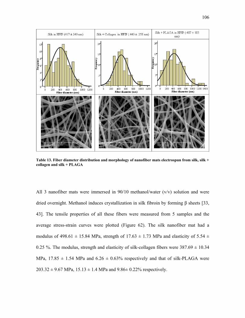
106
Table 13. Fiber diameter distribution and morphology of nanofiber mats electrospun from silk, silk + collagen and silk + PLAGA
All 3 nanofiber mats were immersed in 90/10 methanol/water (v/v) solution and were
dried overnight. Methanol induces crystallization in silk fibroin by forming β sheets [33,
43]. The tensile properties of all these fibers were measured from 5 samples and the
average stress-strain curves were plotted (Figure 62). The silk nanofiber mat had a
modulus of 498.61 ± 15.84 MPa, strength of 17.63 ± 1.73 MPa and elasticity of 5.54 ±
0.25 %. The modulus, strength and elasticity of silk-collagen fibers were 387.69 ± 10.34
MPa, 17.85 ± 1.54 MPa and 6.26 ± 0.63% respectively and that of silk-PLAGA were
203.32 ± 9.67 MPa, 15.13 ± 1.4 MPa and 9.86± 0.22% respectively.
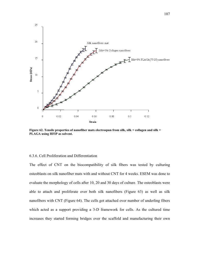
107
Figure 62. Tensile properties of nanofiber mats electrospun from silk, silk + collagen and silk + PLAGA using HFIP as solvent.
6.3.6. Cell Proliferation and Differentiation
The effect of CNT on the biocompatibility of silk fibers was tested by culturing
osteoblasts on silk nanofiber mats with and without CNT for 4 weeks. ESEM was done to
evaluate the morphology of cells after 10, 20 and 30 days of culture. The osteoblasts were
able to attach and proliferate over both silk nanofibers (Figure 63) as well as silk
nanofibers with CNT (Figure 64). The cells got attached over number of underling fibers
which acted as a support providing a 3-D framework for cells. As the cultured time
increases they started forming bridges over the scaffold and manufacturing their own
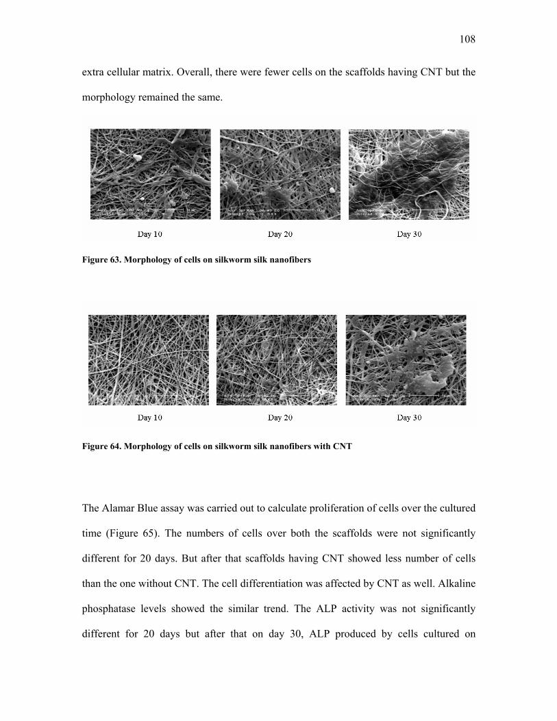
108
extra cellular matrix. Overall, there were fewer cells on the scaffolds having CNT but the
morphology remained the same.
Figure 63. Morphology of cells on silkworm silk nanofibers
Figure 64. Morphology of cells on silkworm silk nanofibers with CNT
The Alamar Blue assay was carried out to calculate proliferation of cells over the cultured
time (Figure 65). The numbers of cells over both the scaffolds were not significantly
different for 20 days. But after that scaffolds having CNT showed less number of cells
than the one without CNT. The cell differentiation was affected by CNT as well. Alkaline
phosphatase levels showed the similar trend. The ALP activity was not significantly
different for 20 days but after that on day 30, ALP produced by cells cultured on
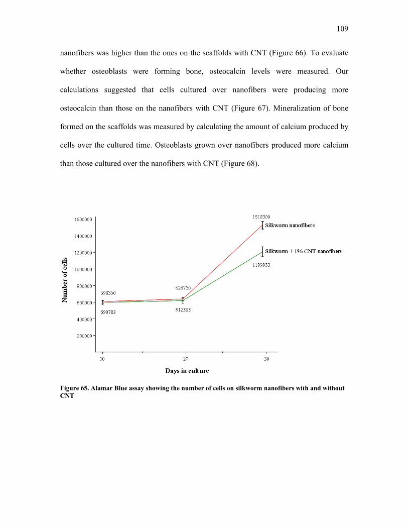
109
nanofibers was higher than the ones on the scaffolds with CNT (Figure 66). To evaluate
whether osteoblasts were forming bone, osteocalcin levels were measured. Our
calculations suggested that cells cultured over nanofibers were producing more
osteocalcin than those on the nanofibers with CNT (Figure 67). Mineralization of bone
formed on the scaffolds was measured by calculating the amount of calcium produced by
cells over the cultured time. Osteoblasts grown over nanofibers produced more calcium
than those cultured over the nanofibers with CNT (Figure 68).
Figure 65. Alamar Blue assay showing the number of cells on silkworm nanofibers with and without CNT
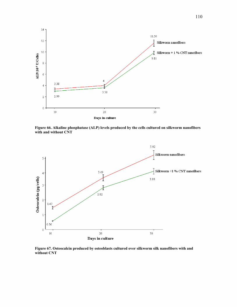
110
Figure 66. Alkaline phosphatase (ALP) levels produced by the cells cultured on silkworm nanofibers with and without CNT
Figure 67. Osteocalcin produced by osteoblasts cultured over silkworm silk nanofibers with and without CNT
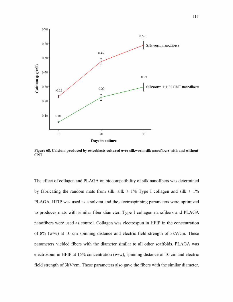
111
Figure 68. Calcium produced by osteoblasts cultured over silkworm silk nanofibers with and without CNT
The effect of collagen and PLAGA on biocompatibility of silk nanofibers was determined
by fabricating the random mats from silk, silk + 1% Type I collagen and silk + 1%
PLAGA. HFIP was used as a solvent and the electrospinning parameters were optimized
to produces mats with similar fiber diameter. Type I collagen nanofibers and PLAGA
nanofibers were used as control. Collagen was electrospun in HFIP in the concentration
of 8% (w/w) at 10 cm spinning distance and electric field strength of 3kV/cm. These
parameters yielded fibers with the diameter similar to all other scaffolds. PLAGA was
electrospun in HFIP at 15% concentration (w/w), spinning distance of 10 cm and electric
field strength of 3kV/cm. These parameters also gave the fibers with the similar diameter.
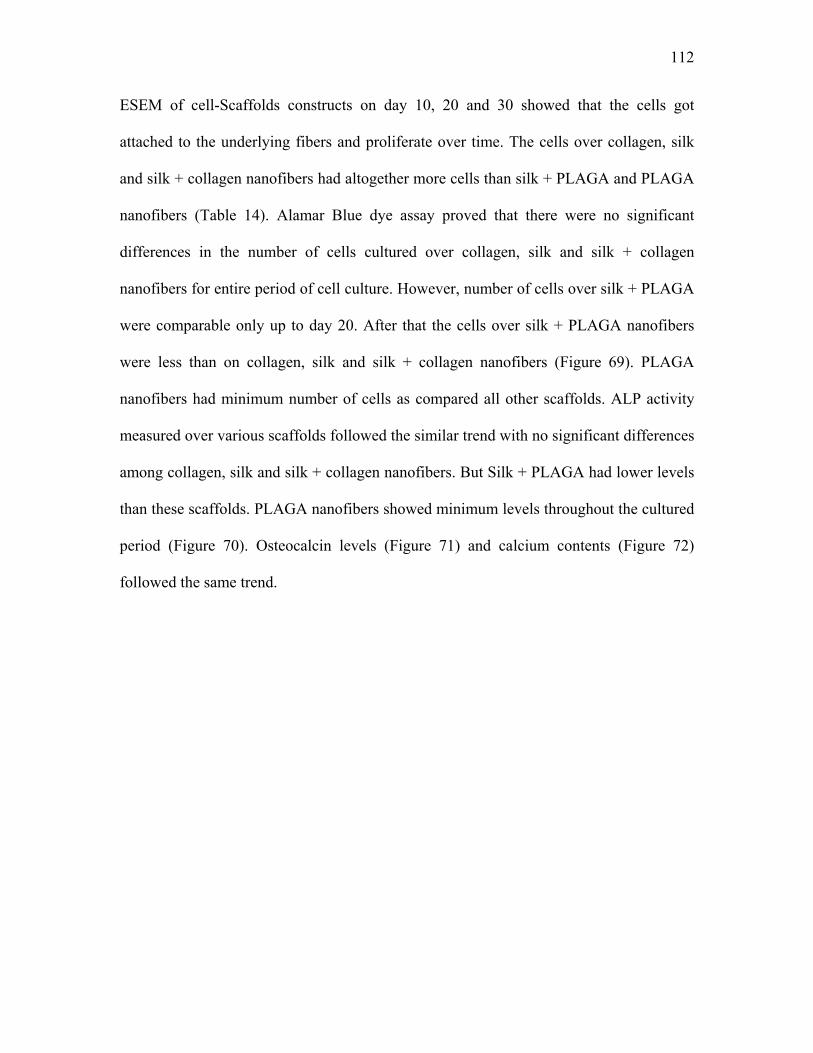
112
ESEM of cell-Scaffolds constructs on day 10, 20 and 30 showed that the cells got
attached to the underlying fibers and proliferate over time. The cells over collagen, silk
and silk + collagen nanofibers had altogether more cells than silk + PLAGA and PLAGA
nanofibers (Table 14). Alamar Blue dye assay proved that there were no significant
differences in the number of cells cultured over collagen, silk and silk + collagen
nanofibers for entire period of cell culture. However, number of cells over silk + PLAGA
were comparable only up to day 20. After that the cells over silk + PLAGA nanofibers
were less than on collagen, silk and silk + collagen nanofibers (Figure 69). PLAGA
nanofibers had minimum number of cells as compared all other scaffolds. ALP activity
measured over various scaffolds followed the similar trend with no significant differences
among collagen, silk and silk + collagen nanofibers. But Silk + PLAGA had lower levels
than these scaffolds. PLAGA nanofibers showed minimum levels throughout the cultured
period (Figure 70). Osteocalcin levels (Figure 71) and calcium contents (Figure 72)
followed the same trend.

113
Figure 69. Alamar Blue assay showing number of cells over cultured time on various silk scaffolds
Figure 70. Alkaline phosphatase (ALP) levels produced by cells over various silk scaffolds
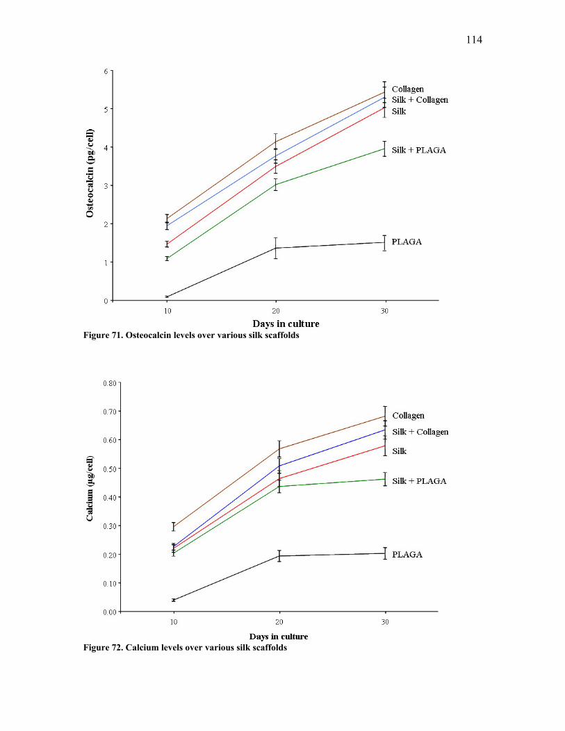
114
Figure 71. Osteocalcin levels over various silk scaffolds
Figure 72. Calcium levels over various silk scaffolds
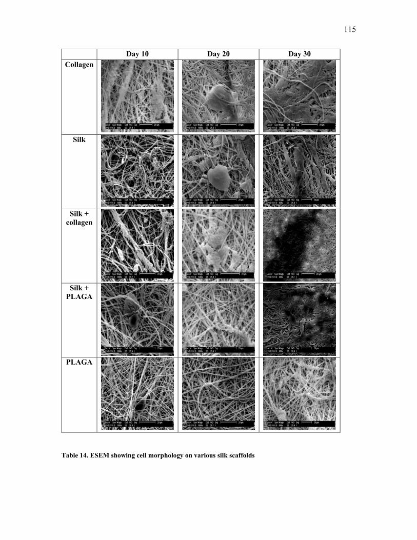
115
Day 10 Day 20 Day 30 Collagen
Silk
Silk +
collagen
Silk +
PLAGA
PLAGA
Table 14. ESEM showing cell morphology on various silk scaffolds
116
6.4. Summary
Various post spinning treatments were carried out to alter the tensile properties of
regenerated silk nanofibers. Methanol causes structural changes in silk protein inducing
formation of β sheets thereby increasing tensile properties. Stretching the nanofibers
cause alignment of fibers in the direction of pull and thus increasing the strength of
fibers. CNT were co-electrospun with silk protein to fabricate nanocomposite nanofibers.
Addition of just 1% CNT increased the strength and toughness of silk fibers significantly.
Raman spectroscopy proved that CNTs were incorporated in the silk fibers. FT-IR
spectroscopy and WAXD studies showed that silk-CNT nanofibers had more crystallinity
compared to silk nanofibers without CNT. This may be because CNT acts as a nucleating
agent increasing the formation of crystals in silk protein. Not only mechanical properties
but electrical conductivity was increased as well with CNT. Blends of silk-collagen and
silk-PLAGA were electrospun to fabricate hybrid protein nanofibers. Elasticity of silk
nanofibers was increased with the incorporation of collagen and PLAGA. Nanofibers-
cells interaction was carried out by culturing primary fetal bovine osteoblasts over the
scaffolds for 4 weeks. Silk-CNT nanofibers had few cells and differentiated little less
than the cells cultured on silk nanofibers without CNT but the cell morphology was
similar. Silk nanofibers had comparable biocompatibility to collagen nanofibers. This
proves that silk can be used instead of collagen in fabricating Tissue Engineering
scaffolds. PLAGA’s biocompatibility increased significantly by incorporating silk in the
nanofibers.
117
CHAPTER 7: NANOFIBROUS SCAFFOLDS FROM SPIDER SILK AND
CARBON NANOTUBES
7.1. Introduction
Silk is an ideal candidate for biomedical applications because of its unique mechanical
properties. The most extensively used silk for various applications are those from
silkworm silk; Bombyx mori and spider silk; Nephila clavipes. Strength and toughness are
usually considered concomitant properties for materials. In the world of natural and
synthetic fibers, spider silk has long been recognized as the model fiber for its unique
combination of high strength and breaking elongation. The spider silk is three times
tougher than aramid fibers and five times stronger than steel [29, 127]. Bombyx mori silk
is available in abundant amount by sericulture but it is not equitable to grow spiders in
the farm due to the cannibalistic nature of spiders. The advances in genetic engineering
and biotechnology have allowed the scientists to produce recombinant spider silk protein
in variety of host organisms. The scientists can now introduce the fiber forming genes
from spider into variety of bacterial (Escherichia coli), fungal (Pichia pastoris), plants
and animal cells to produce recombinant silk [24, 51, 53, 56, 128-130]. Novel silk based
proteins have been engineered by combining silk repeats with similar structural repeats
such as elastin, collagen and cell attachment domain of fibronectin [59-63]. Dragline silk
from Nephila clavipes is made up of two segments, MaSp1 (Major Ampullate Spidroin 1)
and MaSp2 (Major Ampullate Spidroin 2) coded by different genes [24, 25]. Nexia
Biotechnologies Inc., in 1999 introduced an innovative technology of using transgenic
118
approach to produce recombinant spider silk. They introduced spider silk DNA in to goat
to produce recombinant spider silk, BiosteelR [56, 57]. The milk produced by Nexia’s
transgenic goats contains spider silk proteins which can be isolated and purified to
homogeneity. They have successfully generated both MaSp1 and MaSp2 in their goat
system. While the biotechnology pathway to large scale manufacturing of spider silk is
promising, the strength of the synthetic silks produced from these feed stocks is far from
satisfactory in spite of its high level of elongation at break [56]. To address the issue of
low strength of the regenerated transgenic spider silk we propose a hybrid nanocomposite
approach. With a Young’s modulus of 1 TPa and strength of 30-60 GPa at breaking
elongation ranging from 6-30%, CNT is an ideal reinforcing material to strengthen the
regenerated spider silk [90, 92, 131, 132]. By taking advantage of the superior properties
of CNT and ductile silk polymer matrix a new hybrid molecular structure may be
produced. To maximize the reinforcement effect of CNT we decided to use
electrospinning process which is known to be an effective means to align CNT in a
polymer fibril matrix [133]. Nanofibrous structures fabricated by the electrospinning
process are characterized by ultrahigh surface area to volume ratio with morphology
similar to natural extracellular matrices, a wide range of pore size distribution, and a high
porosity. These structures are the ideal candidate for Tissue Engineering scaffolds. The
transgenic spider silk reinforced with CNT will not only have superior mechanical
properties but will also be endowed with electrical conductivity necessary for the growth
of certain cells on scaffolds. MaSp1 and MaSp2 in different ratios were electrospun using
formic acid as a solvent to obtain nanofibers. The process optimization was carried out to
obtain continuous and uniform nanofibers without droplets or beads. Both random and
119
aligned fibers were fabricated. The aligned fibers were obtained using secondary
collection plate technique described earlier in section 5.2.2. The aligned fibers were used
to calculate mechanical properties. MaSp1 fibers were reinforced with CNT and their
mechanical properties were evaluated. The morphology and fiber diameter distribution of
various samples were examined by ESEM. The structure and composition of nanofibers
were characterized by FTIR and the presence of CNT in MaSp1 was determined by
Raman spectroscopy. To explore the feasibility of the spider silk as tissue engineering
scaffolds bovine osteoblasts were cultured on the nanofiber mats of MaSp1 with and
without CNT.
7.2. Materials and Methods
7.2.1. Process Optimization and Characterization
MaSp1 and MaSp2 proteins obtained from Nexia Biotechnologies were dissolved in
various ratios (1:0, 1:1, 1:3, 3:1, 0:1) in 98-100% formic acid (Sigma Aldrich) to prepare
the spinning dope for electrospinning. The spider silk-formic acid solution was
transferred to 3 ml syringe with 18-G needle and electrospun at a 45° spinning angle. The
processing parameters like concentration, spinning distance and charge density were
varied to obtain uniform nano scale silk fibers. The morphology of the palladium
sputtered electrospun fibers was examined and their diameters were determined by
ESEM. The average fiber diameter and its distribution were determined based on 100
random measurements. The composition of silk fibers was characterized by FT-IR
spectrometer. The aligned fibers obtained by secondary collection plate technique were
120
used to calculate tensile properties. The 4 cm long aligned fiber yarn was glued from both
the sides on a paper frame having 1 cm length. These samples were then mounted on a
KES-G1 Kawabata micro tensile tester and the tensile properties were measured from the
average of five samples. The conversion of data was done in a similar way described in
section 5.2.2 of Chapter 5.
7.2.2. Co-electrospinning MaSp1 and Carbon Nanotubes
The CNTs were added only to MaSp1. Purified CNTs processed by high-pressure carbon
monoxide (HiPCO) method were dispersed in formic acid by sonication for 2 hrs. MaSp1
was added to this mixture and again sonicated for one more hour. This mixture was then
stirred for one hour prior to spinning. The morphology and fiber diameter were calculated
by ESEM. Raman Spectroscopy was used to determine the incorporation of CNT in
MaSp1. The mechanical properties of aligned fiber yarn made up of MaSp1 with and
without CNT were measured to evaluate the effect of CNT on mechanical properties.
Electrical conductivity of nanofiber mats from MaSp1 with and without CNT was
calculated by Four-probe method explained in section 6.2.2 of Chapter 6.
7.2.3. Cell-scaffolds Interaction
To evaluate the effect of CNT on the biocompatibility the cell-scaffolds interaction was
carried out using bovine osteoblasts on MaSp1 nanofiber mats with and without CNT.
The cell proliferation was measured using Alamar Blue dye assay. The differentiation
was evaluated by measuring alkaline phosphatase (p-NPP method), osteocalcin (Enzyme
121
linked immunoassay) and calcium (o-cresolphthalin compexone method) levels similar to
the methods described in section 5.2.3 of Chapter 5.
7.3. Results
7.3.1. Fiber Diameter Distribution
We found that 10 cm spinning distance and electric field of 3kV/cm were ideal conditions
for electrospinning MaSp1 and MaSp2. However, concentration was found to be a
dominant factor determining not only the spinability of fibers but also their diameter
(Table 15). 12% concentration of MaSp1 at these conditions produced continuous
uniform fibers with diameter 100.7± 36.43 nm. A stable Taylor cone was formed at the
tip of the spinneret. Formic acid evaporated while the jet was attracted towards the
grounded target making solid nanofibers. MaSp2 by itself was not spinnable at any
conditions producing droplets instead of fibers. When higher concentration of MaSp2
was used at 10 cm spinning distance and electric field of 3kV/cm beads were produced
which were interconnected with fibers. At 12% it produced beads with the fiber diameter
of 28.7± 17.48 nm. The 3:1 ratio of MaSp1 to MaSp2 was spinnable at 12% but for 1:1
and 1:3, viscosity was too high and had to reduce the concentration to 10% and 6%
respectively to obtain continuous and uniform fibers. Deitzel et al. [47] demonstrated the
importance of viscosity, concentrations, spinning distance and the range of other
processing parameters from which continuous nanofibers can be obtained in
electrospinning. Our results were consistent with the previous reported studies. 3:1 ratio
at 12% concentration, 10 cm spinning distance and charge density of 3kV/cm produced
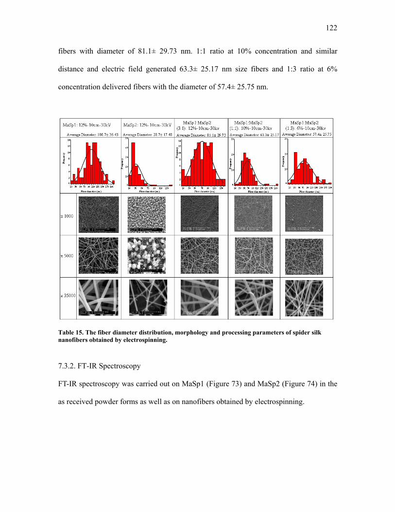
122
fibers with diameter of 81.1± 29.73 nm. 1:1 ratio at 10% concentration and similar
distance and electric field generated 63.3± 25.17 nm size fibers and 1:3 ratio at 6%
concentration delivered fibers with the diameter of 57.4± 25.75 nm.
Table 15. The fiber diameter distribution, morphology and processing parameters of spider silk nanofibers obtained by electrospinning.
7.3.2. FT-IR Spectroscopy
FT-IR spectroscopy was carried out on MaSp1 (Figure 73) and MaSp2 (Figure 74) in the
as received powder forms as well as on nanofibers obtained by electrospinning.
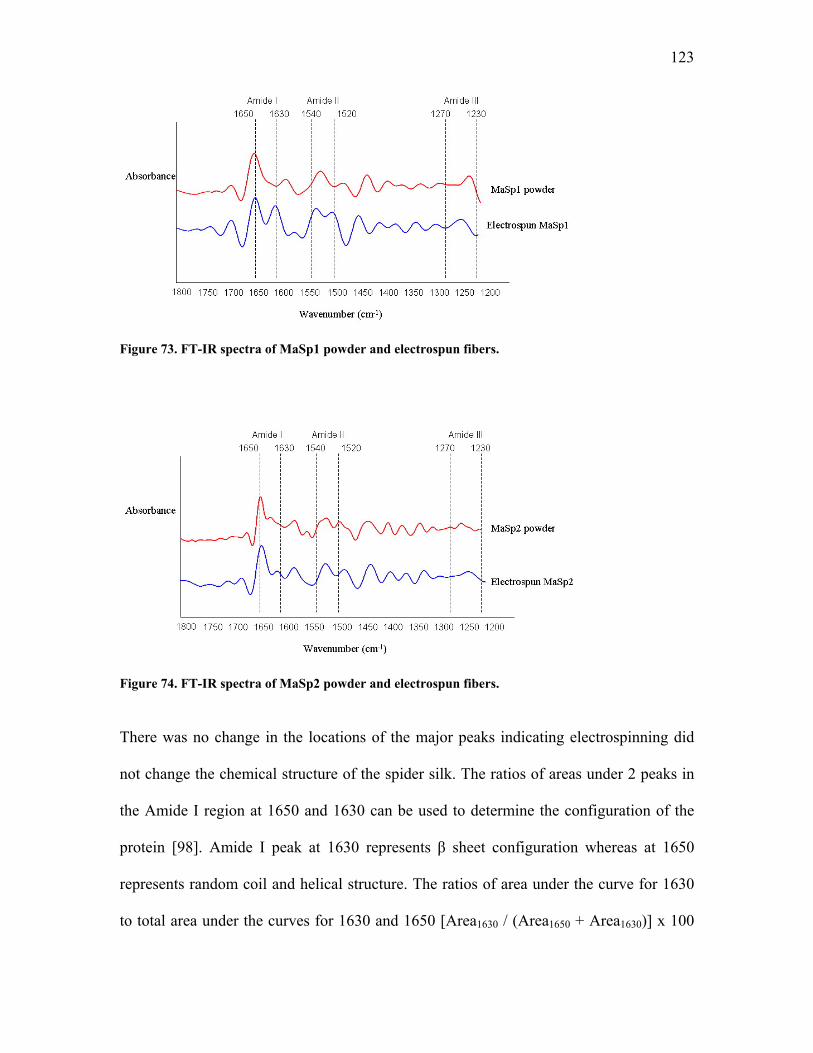
123
Figure 73. FT-IR spectra of MaSp1 powder and electrospun fibers.
Figure 74. FT-IR spectra of MaSp2 powder and electrospun fibers.
There was no change in the locations of the major peaks indicating electrospinning did
not change the chemical structure of the spider silk. The ratios of areas under 2 peaks in
the Amide I region at 1650 and 1630 can be used to determine the configuration of the
protein [98]. Amide I peak at 1630 represents β sheet configuration whereas at 1650
represents random coil and helical structure. The ratios of area under the curve for 1630
to total area under the curves for 1630 and 1650 [Area1630 / (Area1650 + Area1630)] x 100
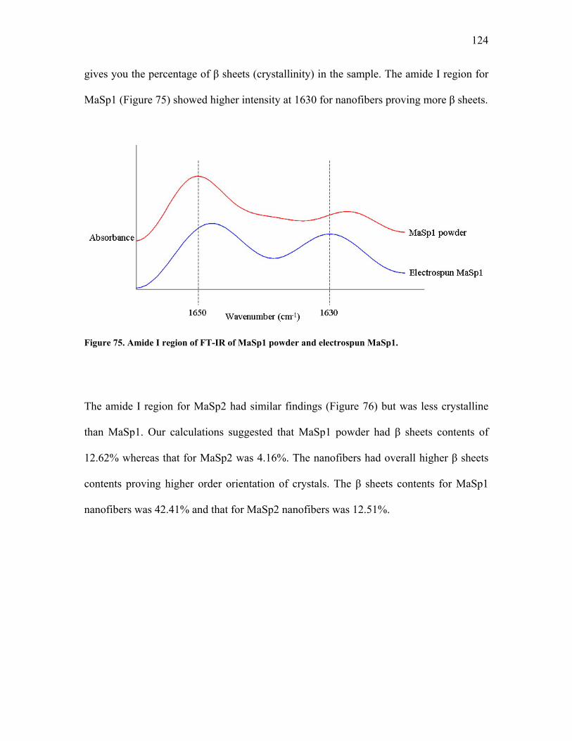
124
gives you the percentage of β sheets (crystallinity) in the sample. The amide I region for
MaSp1 (Figure 75) showed higher intensity at 1630 for nanofibers proving more β sheets.
Figure 75. Amide I region of FT-IR of MaSp1 powder and electrospun MaSp1.
The amide I region for MaSp2 had similar findings (Figure 76) but was less crystalline
than MaSp1. Our calculations suggested that MaSp1 powder had β sheets contents of
12.62% whereas that for MaSp2 was 4.16%. The nanofibers had overall higher β sheets
contents proving higher order orientation of crystals. The β sheets contents for MaSp1
nanofibers was 42.41% and that for MaSp2 nanofibers was 12.51%.
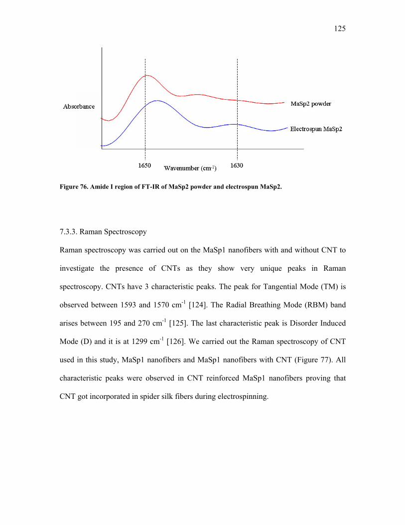
125
Figure 76. Amide I region of FT-IR of MaSp2 powder and electrospun MaSp2.
7.3.3. Raman Spectroscopy
Raman spectroscopy was carried out on the MaSp1 nanofibers with and without CNT to
investigate the presence of CNTs as they show very unique peaks in Raman
spectroscopy. CNTs have 3 characteristic peaks. The peak for Tangential Mode (TM) is
observed between 1593 and 1570 cm-1 [124]. The Radial Breathing Mode (RBM) band
arises between 195 and 270 cm-1 [125]. The last characteristic peak is Disorder Induced
Mode (D) and it is at 1299 cm-1 [126]. We carried out the Raman spectroscopy of CNT
used in this study, MaSp1 nanofibers and MaSp1 nanofibers with CNT (Figure 77). All
characteristic peaks were observed in CNT reinforced MaSp1 nanofibers proving that
CNT got incorporated in spider silk fibers during electrospinning.
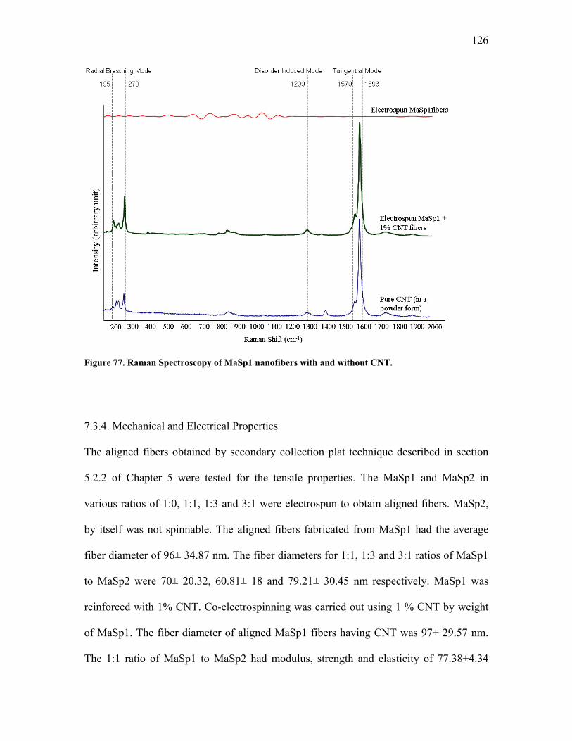
126
Figure 77. Raman Spectroscopy of MaSp1 nanofibers with and without CNT.
7.3.4. Mechanical and Electrical Properties
The aligned fibers obtained by secondary collection plat technique described in section
5.2.2 of Chapter 5 were tested for the tensile properties. The MaSp1 and MaSp2 in
various ratios of 1:0, 1:1, 1:3 and 3:1 were electrospun to obtain aligned fibers. MaSp2,
by itself was not spinnable. The aligned fibers fabricated from MaSp1 had the average
fiber diameter of 96± 34.87 nm. The fiber diameters for 1:1, 1:3 and 3:1 ratios of MaSp1
to MaSp2 were 70± 20.32, 60.81± 18 and 79.21± 30.45 nm respectively. MaSp1 was
reinforced with 1% CNT. Co-electrospinning was carried out using 1 % CNT by weight
of MaSp1. The fiber diameter of aligned MaSp1 fibers having CNT was 97± 29.57 nm.
The 1:1 ratio of MaSp1 to MaSp2 had modulus, strength and elasticity of 77.38±4.34
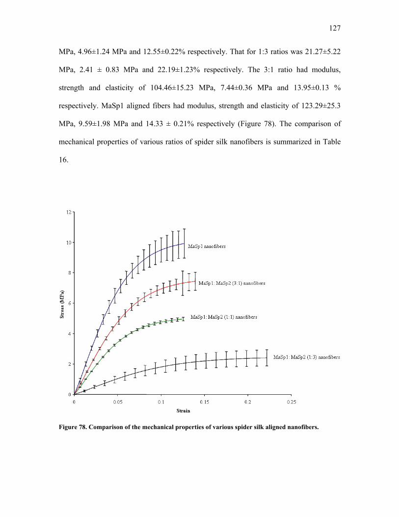
127
MPa, 4.96±1.24 MPa and 12.55±0.22% respectively. That for 1:3 ratios was 21.27±5.22
MPa, 2.41 ± 0.83 MPa and 22.19±1.23% respectively. The 3:1 ratio had modulus,
strength and elasticity of 104.46±15.23 MPa, 7.44±0.36 MPa and 13.95±0.13 %
respectively. MaSp1 aligned fibers had modulus, strength and elasticity of 123.29±25.3
MPa, 9.59±1.98 MPa and 14.33 ± 0.21% respectively (Figure 78). The comparison of
mechanical properties of various ratios of spider silk nanofibers is summarized in Table
16.
Figure 78. Comparison of the mechanical properties of various spider silk aligned nanofibers.
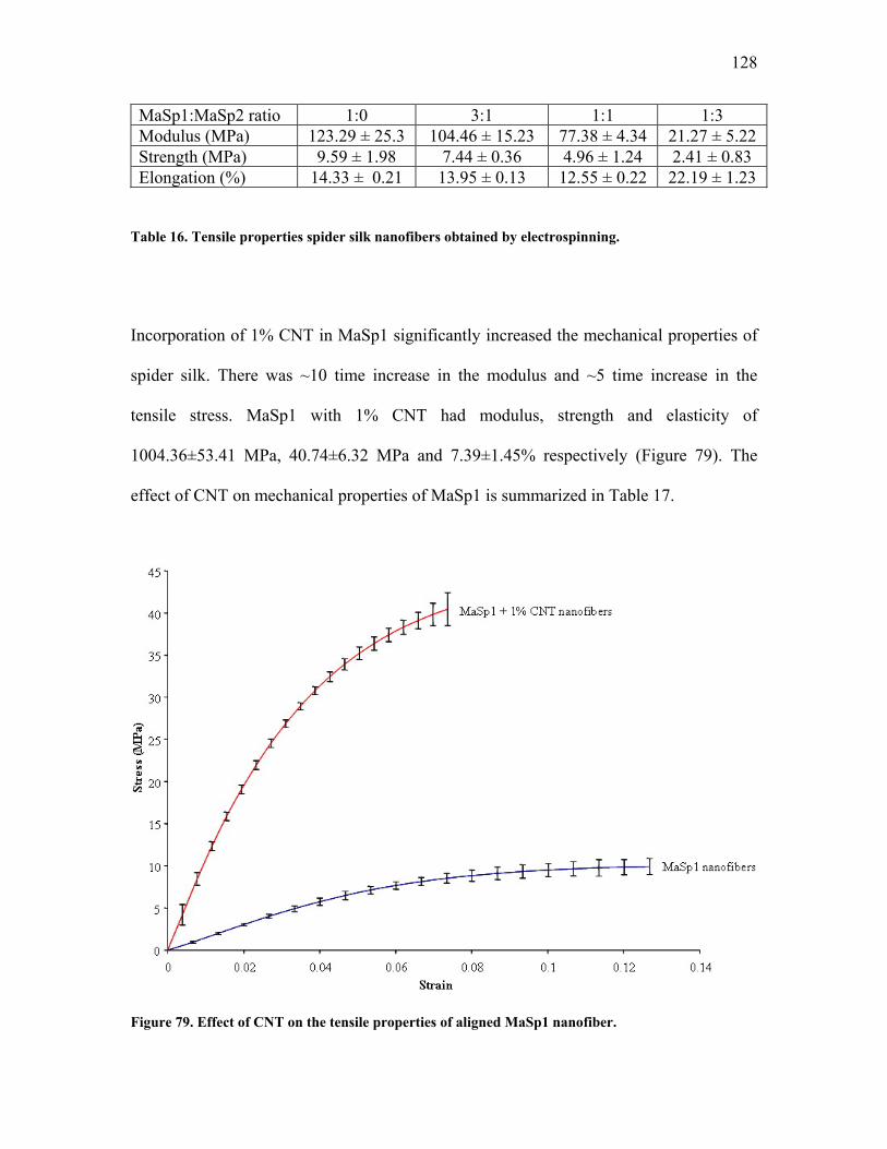
128
MaSp1:MaSp2 ratio 1:0 3:1 1:1 1:3 Modulus (MPa) 123.29 ± 25.3 104.46 ± 15.23 77.38 ± 4.34 21.27 ± 5.22 Strength (MPa) 9.59 ± 1.98 7.44 ± 0.36 4.96 ± 1.24 2.41 ± 0.83 Elongation (%) 14.33 ± 0.21 13.95 ± 0.13 12.55 ± 0.22 22.19 ± 1.23
Table 16. Tensile properties spider silk nanofibers obtained by electrospinning.
Incorporation of 1% CNT in MaSp1 significantly increased the mechanical properties of
spider silk. There was ~10 time increase in the modulus and ~5 time increase in the
tensile stress. MaSp1 with 1% CNT had modulus, strength and elasticity of
1004.36±53.41 MPa, 40.74±6.32 MPa and 7.39±1.45% respectively (Figure 79). The
effect of CNT on mechanical properties of MaSp1 is summarized in Table 17.
Figure 79. Effect of CNT on the tensile properties of aligned MaSp1 nanofiber.
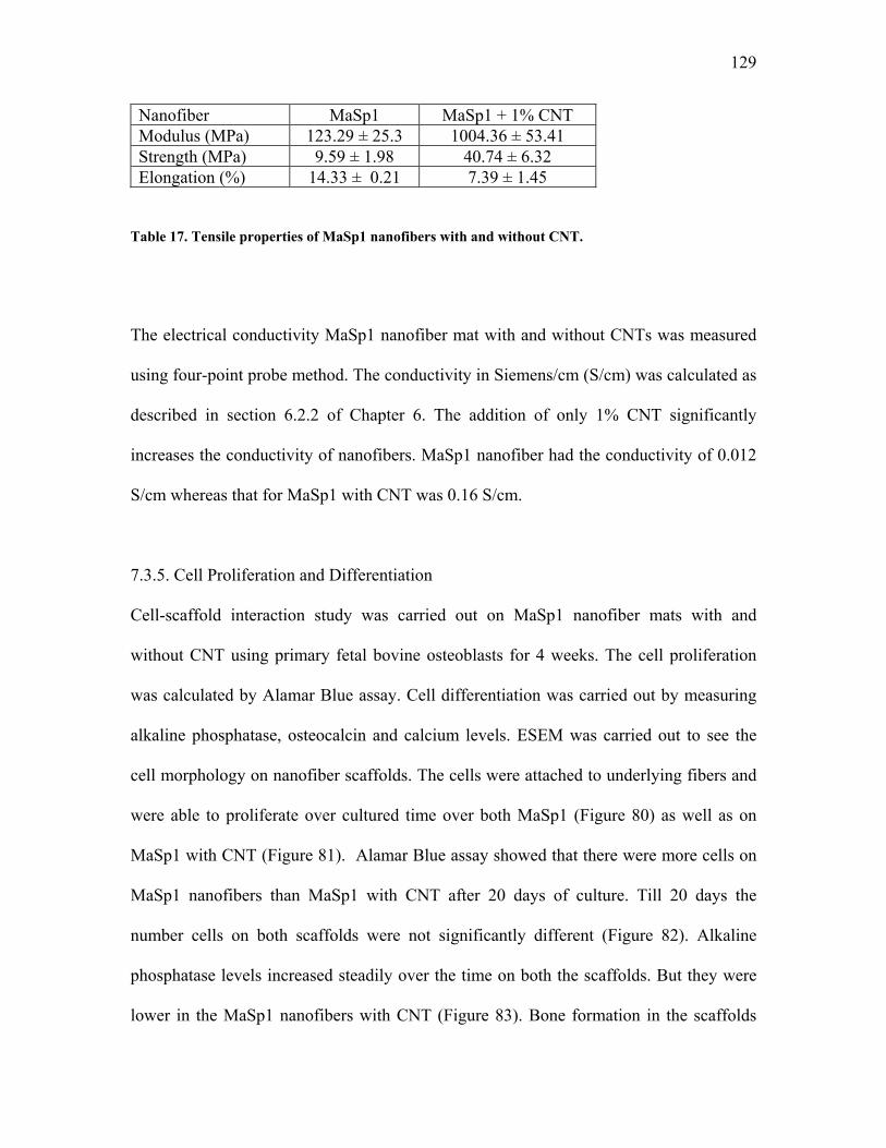
129
Nanofiber MaSp1 MaSp1 + 1% CNT Modulus (MPa) 123.29 ± 25.3 1004.36 ± 53.41 Strength (MPa) 9.59 ± 1.98 40.74 ± 6.32 Elongation (%) 14.33 ± 0.21 7.39 ± 1.45
Table 17. Tensile properties of MaSp1 nanofibers with and without CNT.
The electrical conductivity MaSp1 nanofiber mat with and without CNTs was measured
using four-point probe method. The conductivity in Siemens/cm (S/cm) was calculated as
described in section 6.2.2 of Chapter 6. The addition of only 1% CNT significantly
increases the conductivity of nanofibers. MaSp1 nanofiber had the conductivity of 0.012
S/cm whereas that for MaSp1 with CNT was 0.16 S/cm.
7.3.5. Cell Proliferation and Differentiation
Cell-scaffold interaction study was carried out on MaSp1 nanofiber mats with and
without CNT using primary fetal bovine osteoblasts for 4 weeks. The cell proliferation
was calculated by Alamar Blue assay. Cell differentiation was carried out by measuring
alkaline phosphatase, osteocalcin and calcium levels. ESEM was carried out to see the
cell morphology on nanofiber scaffolds. The cells were attached to underlying fibers and
were able to proliferate over cultured time over both MaSp1 (Figure 80) as well as on
MaSp1 with CNT (Figure 81). Alamar Blue assay showed that there were more cells on
MaSp1 nanofibers than MaSp1 with CNT after 20 days of culture. Till 20 days the
number cells on both scaffolds were not significantly different (Figure 82). Alkaline
phosphatase levels increased steadily over the time on both the scaffolds. But they were
lower in the MaSp1 nanofibers with CNT (Figure 83). Bone formation in the scaffolds
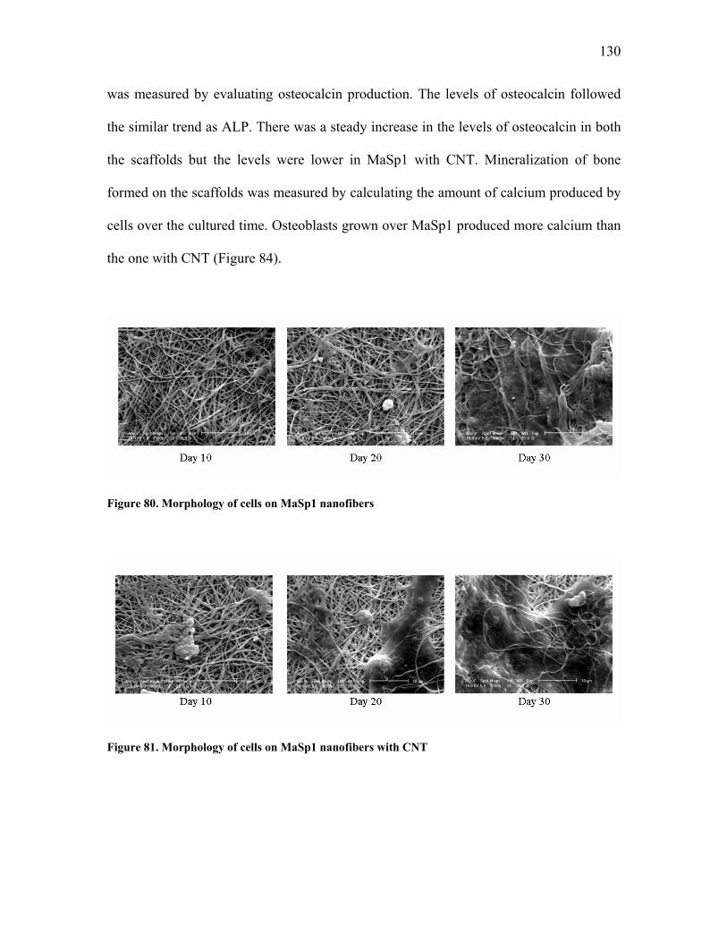
130
was measured by evaluating osteocalcin production. The levels of osteocalcin followed
the similar trend as ALP. There was a steady increase in the levels of osteocalcin in both
the scaffolds but the levels were lower in MaSp1 with CNT. Mineralization of bone
formed on the scaffolds was measured by calculating the amount of calcium produced by
cells over the cultured time. Osteoblasts grown over MaSp1 produced more calcium than
the one with CNT (Figure 84).
Figure 80. Morphology of cells on MaSp1 nanofibers
Figure 81. Morphology of cells on MaSp1 nanofibers with CNT
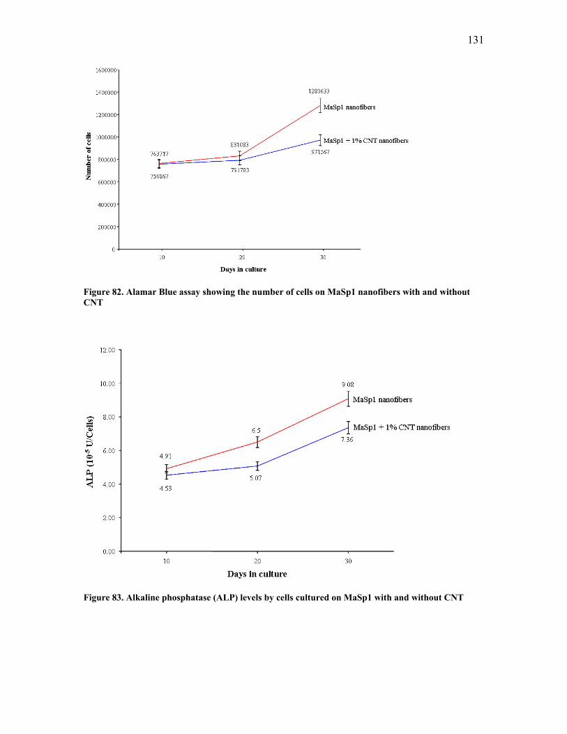
131
Figure 82. Alamar Blue assay showing the number of cells on MaSp1 nanofibers with and without CNT
Figure 83. Alkaline phosphatase (ALP) levels by cells cultured on MaSp1 with and without CNT
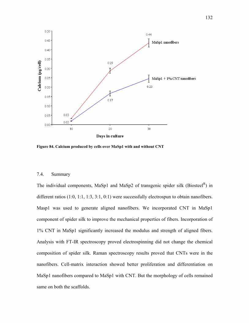
132
Figure 84. Calcium produced by cells over MaSp1 with and without CNT
7.4. Summary
The individual components, MaSp1 and MaSp2 of transgenic spider silk (BiosteelR) in
different ratios (1:0, 1:1, 1:3, 3:1, 0:1) were successfully electrospun to obtain nanofibers.
Masp1 was used to generate aligned nanofibers. We incorporated CNT in MaSp1
component of spider silk to improve the mechanical properties of fibers. Incorporation of
1% CNT in MaSp1 significantly increased the modulus and strength of aligned fibers.
Analysis with FT-IR spectroscopy proved electrospinning did not change the chemical
composition of spider silk. Raman spectroscopy results proved that CNTs were in the
nanofibers. Cell-matrix interaction showed better proliferation and differentiation on
MaSp1 nanofibers compared to MaSp1 with CNT. But the morphology of cells remained
same on both the scaffolds.
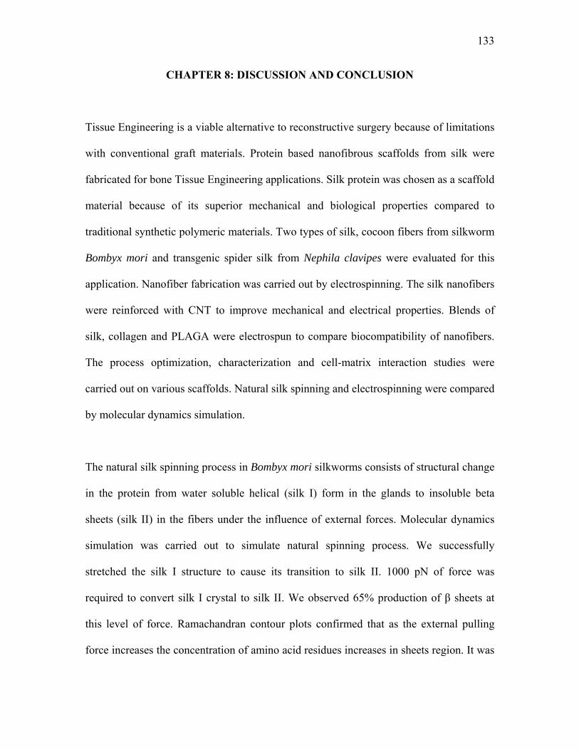
133
CHAPTER 8: DISCUSSION AND CONCLUSION
Tissue Engineering is a viable alternative to reconstructive surgery because of limitations
with conventional graft materials. Protein based nanofibrous scaffolds from silk were
fabricated for bone Tissue Engineering applications. Silk protein was chosen as a scaffold
material because of its superior mechanical and biological properties compared to
traditional synthetic polymeric materials. Two types of silk, cocoon fibers from silkworm
Bombyx mori and transgenic spider silk from Nephila clavipes were evaluated for this
application. Nanofiber fabrication was carried out by electrospinning. The silk nanofibers
were reinforced with CNT to improve mechanical and electrical properties. Blends of
silk, collagen and PLAGA were electrospun to compare biocompatibility of nanofibers.
The process optimization, characterization and cell-matrix interaction studies were
carried out on various scaffolds. Natural silk spinning and electrospinning were compared
by molecular dynamics simulation.
The natural silk spinning process in Bombyx mori silkworms consists of structural change
in the protein from water soluble helical (silk I) form in the glands to insoluble beta
sheets (silk II) in the fibers under the influence of external forces. Molecular dynamics
simulation was carried out to simulate natural spinning process. We successfully
stretched the silk I structure to cause its transition to silk II. 1000 pN of force was
required to convert silk I crystal to silk II. We observed 65% production of β sheets at
this level of force. Ramachandran contour plots confirmed that as the external pulling
force increases the concentration of amino acid residues increases in sheets region. It was
134
not possible to apply more than 1000 pN of force as the force was too high for the model
peptide system to tolerate causing the simulation to become unstable. Natural silk
spinning process is results of billions of years of evolution. This topic has remained a
subject of curiosity for decades. Silkworms and spiders spin fibers at ambient conditions
and can produce fibers with remarkable combination of strength and toughness. Industrial
fibers with comparable mechanical properties require use of harsh chemicals for their
production. Knowledge on the structural changes during natural silk spinning helps in the
development of an artificial spinning system that can mimic these conditions. Silk protein
has to be converted to regenerated silk in order to make it soluble in an appropriate
solvent. By mimicking the natural spinning process a protocol was established to make a
spinnable dope from Bombyx mori cocoon fibers. The steps required to prepare
regenerated silk were simulated using molecular dynamics process. The fabrication of
regenerated silk involves dissolving cocoon fibers in CaCl2, dialyzing the silk-CaCl2
solution against water and then freeze drying the silk-water solution. The natural silk
cocoon fibers which are predominantly in β sheets configuration on coming in contact
with CaCl2 starts to relax. The intra and inter molecular hydrogen bonds are broken and β
sheets are converted into random coils. During the process of dialysis CaCl2 is replaced
by water molecules. During this process some of the hydrogen bonds are reformed. When
water is removed by lyophilization more hydrogen bonds are formed. This structure of
regenerated silk protein is less packed and they have free groups on amino acids to react
with the solvent molecules. Because of this it is easier to dissolve regenerated silk in
formic acid whereas natural cocoon fibers are insoluble in it. Our simulation showed a
minimum β sheets content in silk fibers dissolved in CaCl2. This was then followed by a
135
steady increase at various stages of fabrication of regenerated silk protein. After
electrospinning and methanol treatment β sheets content was nearly similar to natural
fibers. We believe that the electric field applied during the process of electrospinning has
similar drawing effect on silk protein as in natural spinning process. Even though the
structure of silk nanofibers is not exactly similar to cocoon fibers it is an economic way
of generating artificial fibers from silk.
The regenerated silk was successfully electrospun in formic acid to generate nanofibers.
A detailed investigation on process optimization was carried out. The concentration of
regenerated silk solution was the most dominant parameter to produce nanofibers.
Uniform fibers with diameter less than 100 nm were produced in the spinning conditions
of concentration range 12 to 15% (w/w) and charge density of 3kv/cm to 4kv/cm.
Secondary collection plate technique was found to be an effective way of fabricating
aligned nanofibers. Post spinning treatment with methanol and stretching increased the
mechanical properties significantly. These treatments improved the crystallinity of fibers
as well which was investigated by FT-IR and WAXD studies. Methanol induces the
formation of β sheets in nanofibers. Stretching helps in aligning the fibers to the direction
of pull. We were successfully able to incorporate CNT in nanofibers as evident from
Raman spectroscopy. FT-IR spectroscopy and WAXD studies showed that silk-CNT
nanofibers had more crystallinity compared to silk nanofibers without CNT. We believe
that CNT acts as nucleating site for the growth of β sheets crystals. The strength and
toughness of silk fibers were significantly increased upon addition of just 1% CNT.
Electrical conductivity was improved as well with CNT. We were successful in
136
electrospinning blends of silk-collagen and silk-PLAGA. The elasticity of fibers was
increased with collagen and PLAGA. These results can be useful in generating scaffolds
for specific tissues. Various combinations of CNT, PLAGA and collagen can be
evaluated to fabricate scaffolds having properties similar to the replacing tissue. Cell-
matrix interaction study using primary fetal bovine osteoblasts proved that silk nanofibers
are osteoconductive material allowing the proliferation and differentiation of cells
cultured on them. Nanofibers had more cell growth as well as differentiation as compared
to micron sized cocoon fibers. This was tested by Alamar Blue dye assay and measuring
the levels of alkaline phosphatase, osteocalcin and calcium. The morphology of cells on
nanofibers was significantly different than microfibers. Nanofibers have high surface area
to volume ratio and are endowed with higher porosity than micron sized fibers. They
have the architecture similar to the natural extra cellular matrix. Osteoblasts on
nanofibers with CNT had few cells and differentiated little less than the cells cultured on
silk nanofibers without CNT. But they had comparable morphology. The cell growth and
differentiation was more on nanofibers with CNT as well compared to natural cocoon
fibers. The biocompatibility of silk nanofibers was found to be similar to collagen
nanofibers and significantly higher than PLAGA nanofibers. Protein based materials have
favorable cell interaction and non toxic degradation products thus are much superior to
synthetic polymer.
Our study not only proved that it is possible to fabricate nanofibers from regenerated
silkworm silk but also from transgenic spider silk. Individual components MaSp1 and
MaSp2 of spider silk were successfully electrospun in formic acid to fabricate nanofibers.
137
MaSp1 was found to be more crystalline in nature than MaSp2 based on our findings
from FT-IR. This was reflected in the mechanical properties of various blends of MaSp1
and MaSp2. Increase in the amount of MaSp1 resulted in stronger fibers where as fibers
with higher MaSp2 content were more elastic. A suitable combination of these 2 proteins
can lead to tissue specific fabrication of scaffolds. We were able to incorporate CNT
successfully in MaSp1 nanofibers. Mechanical and electrical properties of MaSp1 silk
polymer was significantly increased upon addition of 1% CNT. Cell-matrix interaction
showed better proliferation and differentiation on MaSp1 nanofibers compared to MaSp1
with CNT. But the morphology of cells remained same on both the scaffolds.
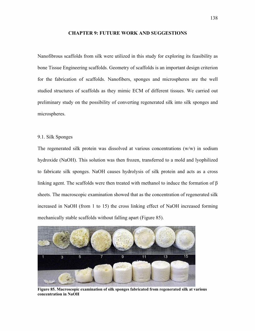
138
CHAPTER 9: FUTURE WORK AND SUGGESTIONS
Nanofibrous scaffolds from silk were utilized in this study for exploring its feasibility as
bone Tissue Engineering scaffolds. Geometry of scaffolds is an important design criterion
for the fabrication of scaffolds. Nanofibers, sponges and microspheres are the well
studied structures of scaffolds as they mimic ECM of different tissues. We carried out
preliminary study on the possibility of converting regenerated silk into silk sponges and
microspheres.
9.1. Silk Sponges
The regenerated silk protein was dissolved at various concentrations (w/w) in sodium
hydroxide (NaOH). This solution was then frozen, transferred to a mold and lyophilized
to fabricate silk sponges. NaOH causes hydrolysis of silk protein and acts as a cross
linking agent. The scaffolds were then treated with methanol to induce the formation of β
sheets. The macroscopic examination showed that as the concentration of regenerated silk
increased in NaOH (from 1 to 15) the cross linking effect of NaOH increased forming
mechanically stable scaffolds without falling apart (Figure 85).
Figure 85. Macroscopic examination of silk sponges fabricated from regenerated silk at various concentration in NaOH
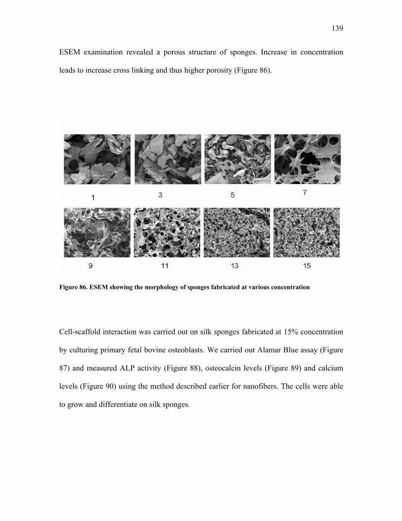
139
ESEM examination revealed a porous structure of sponges. Increase in concentration
leads to increase cross linking and thus higher porosity (Figure 86).
Figure 86. ESEM showing the morphology of sponges fabricated at various concentration
Cell-scaffold interaction was carried out on silk sponges fabricated at 15% concentration
by culturing primary fetal bovine osteoblasts. We carried out Alamar Blue assay (Figure
87) and measured ALP activity (Figure 88), osteocalcin levels (Figure 89) and calcium
levels (Figure 90) using the method described earlier for nanofibers. The cells were able
to grow and differentiate on silk sponges.
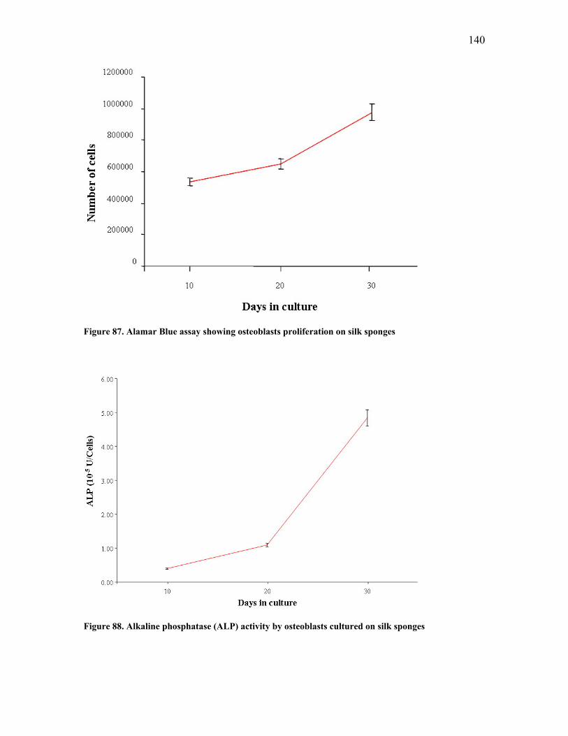
140
Figure 87. Alamar Blue assay showing osteoblasts proliferation on silk sponges
Figure 88. Alkaline phosphatase (ALP) activity by osteoblasts cultured on silk sponges
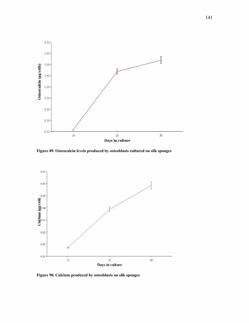
141
Figure 89. Osteocalcin levels produced by osteoblasts cultured on silk sponges
Figure 90. Calcium produced by osteoblasts on silk sponges
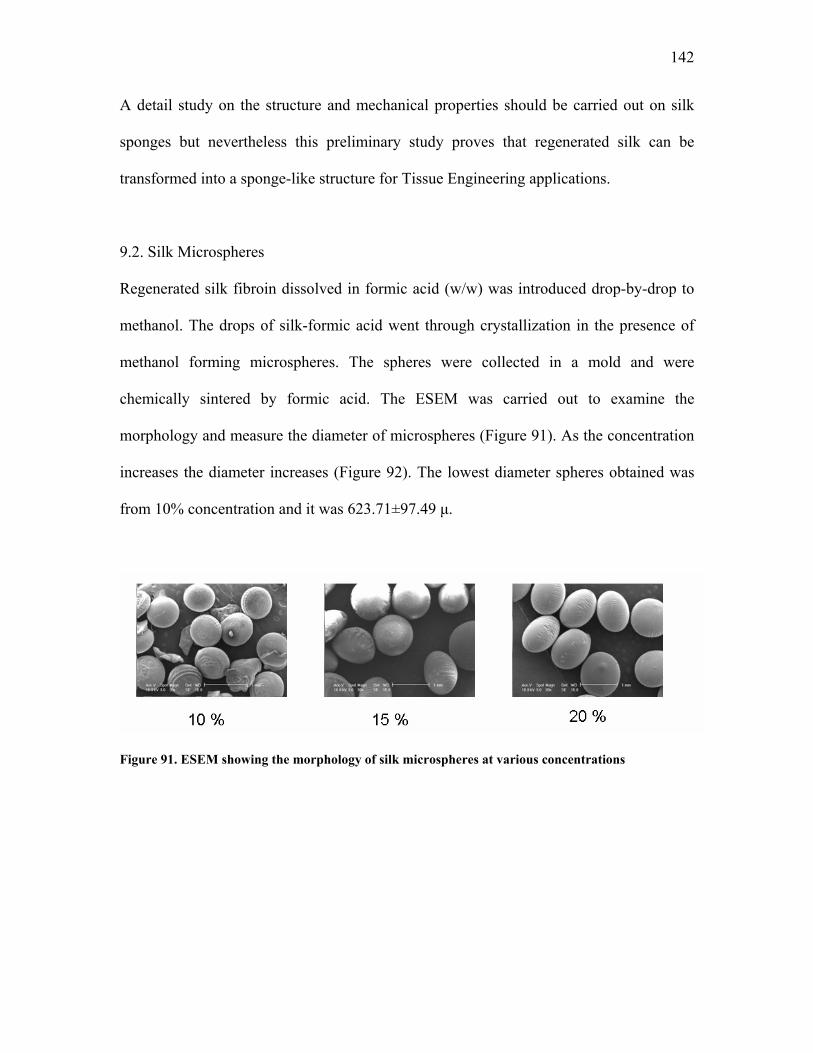
142
A detail study on the structure and mechanical properties should be carried out on silk
sponges but nevertheless this preliminary study proves that regenerated silk can be
transformed into a sponge-like structure for Tissue Engineering applications.
9.2. Silk Microspheres
Regenerated silk fibroin dissolved in formic acid (w/w) was introduced drop-by-drop to
methanol. The drops of silk-formic acid went through crystallization in the presence of
methanol forming microspheres. The spheres were collected in a mold and were
chemically sintered by formic acid. The ESEM was carried out to examine the
morphology and measure the diameter of microspheres (Figure 91). As the concentration
increases the diameter increases (Figure 92). The lowest diameter spheres obtained was
from 10% concentration and it was 623.71±97.49 μ.
Figure 91. ESEM showing the morphology of silk microspheres at various concentrations
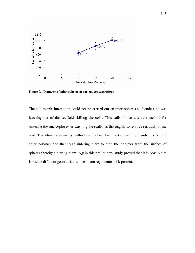
143
Figure 92. Diameter of microspheres at various concentrations The cell-matrix interaction could not be carried out on microspheres as formic acid was
leaching out of the scaffolds killing the cells. This calls for an alternate method for
sintering the microspheres or washing the scaffolds thoroughly to remove residual formic
acid. The alternate sintering method can be heat treatment or making blends of silk with
other polymer and then heat sintering them to melt the polymer from the surface of
spheres thereby sintering them. Again this preliminary study proved that it is possible to
fabricate different geometrical shapes from regenerated silk protein.
144
Other suggestions recommended by us are…
Molecular dynamics simulation
• Using higher force to pull silk model peptide and evaluating the formation of β
sheets.
• Utilizing other repetitive models as silk crystal
Mechanical properties and CNT Reinforcement
• Better dispersion of CNT for maximum translation of CNT properties to silk
matrix
• Determining the methods for quantification of dispersion of CNT
• Using atomic force microscopy, nanoindentation or nanomanipulator devices to
determine single nanofiber properties
Tissue Engineering
• Large scale manufacturing of nanofibers
• Functionalizing nanotubes to improve biocompatibility
• Cell-matrix interaction study using silk-CNT scaffolds in the presence of electric
stimulation
• Developing in vivo models for bone Tissue Engineering using silk scaffolds
• Exploring the use of scaffolds for other tissues
145
LIST OF REFERENCES
1. Skalak, R., C.F. Fox, and Y.C. Fung. Proceedings of NSF workshop on Tissue Engineering in Tissue Engineering. February 26-29, 1988. Granlibakken, Lake Tahoe, California.
2. Friedman, M.J., O.H. Sherman, J.M. Fox, et al., Autogeneic anterior cruciate
ligament (ACL) anterior reconstruction of the knee. A review. Clin Orthop Relat Res, 1985(196): p. 9-14.
3. Langer, R. and J.P. Vacanti, Tissue engineering. Science, 1993. 260(5110): p.
920-6. 4. Gazdag, A.R., J.M. Lane, D. Glaser, et al., Alternatives to Autogenous Bone
Graft: Efficacy and Indications. J Am Acad Orthop Surg, 1995. 3(1): p. 1-8. 5. Jackson, D.W., G.E. Windler, and T.M. Simon, Intraarticular reaction associated
with the use of freeze-dried, ethylene oxide-sterilized bone-patella tendon-bone allografts in the reconstruction of the anterior cruciate ligament. Am J Sports Med, 1990. 18(1): p. 1-10; discussion 10-1.
6. Shino, K., M. Inoue, S. Horibe, et al., Maturation of allograft tendons transplanted
into the knee. An arthroscopic and histological study. J Bone Joint Surg Br, 1988. 70(4): p. 556-60.
7. Attawia, M.A., J.E. Devin, and C.T. Laurencin, Immunofluorescence and
confocal laser scanning microscopy studies of osteoblast growth and phenotypic expression in three-dimensional degradable synthetic matrices. J Biomed Mater Res, 1995. 29(7): p. 843-8.
8. Carrier, R.L., M. Papadaki, M. Rupnick, et al., Cardiac tissue engineering: cell
seeding, cultivation parameters, and tissue construct characterization. Biotechnol Bioeng, 1999. 64(5): p. 580-9.
9. Elisseeff, J., W. McIntosh, K. Fu, et al., Controlled-release of IGF-I and TGF-
beta1 in a photopolymerizing hydrogel for cartilage tissue engineering. J Orthop Res, 2001. 19(6): p. 1098-104.
10. Fleming, J.E., Jr., C.N. Cornell, and G.F. Muschler, Bone cells and matrices in
orthopedic tissue engineering. Orthop Clin North Am, 2000. 31(3): p. 357-74. 11. Jackson, D.W., J.T. Heinrich, and T.M. Simon, Biologic and synthetic implants to
replace the anterior cruciate ligament. Arthroscopy, 1994. 10(4): p. 442-52.
146
12. Shum-Tim, D., U. Stock, J. Hrkach, et al., Tissue engineering of autologous aorta using a new biodegradable polymer. Ann Thorac Surg, 1999. 68(6): p. 2298-304; discussion 2305.
13. Vacanti, J.P. and R. Langer, Tissue engineering: the design and fabrication of
living replacement devices for surgical reconstruction and transplantation. Lancet, 1999. 354(Suppl 1): p. SI32-4.
14. Doshi, J. and D.H. Reneker, Electrospinning process and applications of
electrospun fibers. Journal of Electrostatics, 1995. 35(2-3): p. 151. 15. Li, W.J., C.T. Laurencin, E.J. Caterson, et al., Electrospun nanofibrous structure:
a novel scaffold for tissue engineering. J Biomed Mater Res, 2002. 60(4): p. 613-21.
16. Altman, G.H., F. Diaz, C. Jakuba, et al., Silk-based biomaterials. Biomaterials,
2003. 24(3): p. 401-16. 17. Hyde, N., Silk, the Queen of Textiles. National Geographic Magazine, Jan 1984:
p. 2-49. 18. Brooks, G., Silk Proteins in Cosmetics. Drug and cosmetic industry, 1989. 145(4):
p. 32-36. 19. Ko, F.K. and C.T. Laurencin. Three Dimensional Fibrous Scaffolds for Tissue
Engineering. in Proceedings, NATO Workshop. June 23, 1999. Poznan, Poland. 20. Ko, F.K., C.T. Laurencin, M.D. Borden, et al. The Dynamics of Cell-Fiber
Architecture Interaction. in Proceedings, Annual Meeting, Biomaterials Research Society. April, 1998. San Diego.
21. Sinohara, H., Glycopeptides isolated from sericin of the silkworm, Bombyx mori.
Comparative biochemistry and physiology, 1979. 63B: p. 87-91. 22. Inoue, S., K. Tanaka, F. Arisaka, et al., Silk fibroin of Bombyx mori is secreted,
assembling a high molecular mass elementary unit consisting of H-chain, L-chain, and P25, with a 6:6:1 molar ratio. J Biol Chem, 2000. 275(51): p. 40517-28.
23. Kodrik, D., Small protein components of the cocoons in Galleria mellonella
(Lepidoptera, Pyralidae) and Bombyx mori (Lepidoptera, Bombycidae). Acta Entomol. Bohemoslov., 1992(89): p. 269-273.
24. Lewis, R.V., M. Hinman, S. Kothakota, et al., Expression and purification of a
spider silk protein: a new strategy for producing repetitive proteins. Protein Expr Purif, 1996. 7(4): p. 400-6.
147
25. Xu, M. and R.V. Lewis, Structure of a protein superfiber: spider dragline silk. Proc Natl Acad Sci U S A, 1990. 87(18): p. 7120-4.
26. Zhou, C.Z., F. Confalonieri, N. Medina, et al., Fine organization of Bombyx mori
fibroin heavy chain gene. Nucleic Acids Res, 2000. 28(12): p. 2413-9. 27. Zhou, C.Z., F. Confalonieri, M. Jacquet, et al., Silk fibroin: structural implications
of a remarkable amino acid sequence. Proteins, 2001. 44(2): p. 119-22. 28. Santin, M., A. Motta, G. Freddi, et al., In vitro evaluation of the inflammatory
potential of the silk fibroin. J Biomed Mater Res, 1999. 46(3): p. 382-9. 29. Vollrath, F. and D.P. Knight, Liquid crystalline spinning of spider silk. Nature,
2001. 410(6828): p. 541-8. 30. Vollrath, F., B. Madsen, and Z. Shao, The effect of spinning conditions on the
mechanics of a spider's dragline silk. Proc R Soc Lond B Biol Sci, 2001. 268(1483): p. 2339-46.
31. Vollrath, F., Biology of spider silk. Int J Biol Macromol, 1999. 24(2-3): p. 81-8. 32. Valluzzi, R., S. Winkler, D. Wilson, et al., Silk: molecular organization and
control of assembly. Philos Trans R Soc Lond B Biol Sci, 2002. 357(1418): p. 165-7.
33. Wilson, D., R. Valluzzi, and D. Kaplan, Conformational transitions in model silk
peptides. Biophys J, 2000. 78(5): p. 2690-701. 34. Yao, J., Y. Nakazawa, and T. Asakura, Structures of Bombyx mori and Samia
cynthia ricini silk fibroins studied with solid-state NMR. Biomacromolecules, 2004. 5(3): p. 680-8.
35. Pauling, L. and R.B. Corey, Two Rippled-Sheet Configurations of Polypeptide
Chains, and a Note about the Pleated Sheets. Proc. Natl. Acad. Sci. USA, 1953. 39(4): p. 253-6.
36. Guiyang, L., Z. Ping, S. Zhengzhong, et al., The natural silk spinning process-A
nucleation-dependent aggregation mechanism? Eur. J. Biochem. , 2001(268): p. 6600–6606.
37. Guinea, G.V., M. Elices, J.I. Real, et al., Reproducibility of the tensile properties
of spider (Argiope trifasciata) silk obtained by forced silking. J Exp Zoolog A Comp Exp Biol, 2005. 303(1): p. 37-44.
38. Ortlepp, C.S. and J.M. Gosline, Consequences of forced silking.
Biomacromolecules, 2004. 5(3): p. 727-31.
148
39. Riekel, C. and F. Vollrath, Spider silk fibre extrusion: combined wide- and small-
angle X-ray microdiffraction experiments. Int J Biol Macromol, 2001. 29(3): p. 203-10.
40. Seidel, A., O. Liivak, and L.W. Jelinski, Artificial spinning of spider silk.
Macromolecules, 1998(31): p. 6733-6736. 41. Trabbic, K.A. and P. Yager, Comparative structural characterization of naturally
and synthetically spun fibers of Bombyx mori fibroin. Macromolecules, 1998(31): p. 462-471.
42. Meinel, L., S. Hofmann, V. Karageorgiou, et al., The inflammatory responses to
silk films in vitro and in vivo. Biomaterials, 2005. 26(2): p. 147-55. 43. Um, I.C., H. Kweon, K.G. Lee, et al., Wet spinning of silk polymer. I. Effect of
coagulation conditions on the morphological feature of filament. Int J Biol Macromol, 2004. 34(1-2): p. 89-105.
44. Um, I.C., C.S. Ki, H. Kweon, et al., Wet spinning of silk polymer: II. Effect of
drawing on the structural characteristics and properties of filament. International Journal of Biological Macromolecules, 2004. 34(1-2): p. 107-119.
45. Sukigara, S., M. Gandhi, J. Ayutsede, et al., Regeneration of Bombyx mori silk by
electrospinning-Part 1: processing parameters and geometric properties. Polymer, 2003. 44(19): p. 5721-5727.
46. Kastelic, J., A. Galeski, and E. Baer, Structure and function of mammalian
tendon. Journal of Connective Tissue Research, 1978(6): p. 11-23. 47. Deitzel, J.M., J. Kleinmeyer, D. Harris, et al., The effect of processing variables
on the morphology of electrospun nanofibers and textiles. Polymer, 2001. 42(1): p. 261.
48. L. Larrondo, R.S.J.M., Electrostatic fiber spinning from polymer melts. I.
Experimental observations on fiber formation and properties. Journal of Polymer Science: Polymer Physics Edition, 1981. 19(6): p. 909-920.
49. Shin, Y.M., M.M. Hohman, M.P. Brenner, et al., Electrospinning: A whipping
fluid jet generates submicron polymer fibers. Applied Physics Letters, 2001. 78(8): p. 1149-1151.
50. Shin, Y.M., M.M. Hohman, M.P. Brenner, et al., Experimental characterization of
electrospinning: the electrically forced jet and instabilities. Polymer, 2001. 42(25): p. 09955.
149
51. Fahnestock, S.R., Z. Yao, and L.A. Bedzyk, Microbial production of spider silk proteins. J Biotechnol, 2000. 74(2): p. 105-19.
52. Ohshima, Y. and Y. Suzuki, Cloning of silk fibroin gene and its flanking
sequences. Proc. Natl. Acad. Sci. USA 1977(74): p. 5363-5367. 53. Prince, J.T., K.P. McGrath, C.M. DiGirolamo, et al., Construction, cloning, and
expression of synthetic genes encoding spider dragline silk. Biochemistry, 1995. 34(34): p. 10879-85.
54. Fahnestock, S.R. and L.A. Bedzyk, Production of synthetic spider dragline silk
protein in Pichia pastoris. Appl Microbiol Biotechnol, 1997. 47(1): p. 33-9. 55. Fahnestock, S.R. and S.L. Irwin, Synthetic spider dragline silk proteins and their
production in Escherichia coli. Appl Microbiol Biotechnol, 1997. 47(1): p. 23-32. 56. Lazaris, A., S. Arcidiacono, Y. Huang, et al., Spider silk fibers spun from soluble
recombinant silk produced in mammalian cells. Science, 2002. 295(5554): p. 472-6.
57. Karatzas, C.N., Production of recombinant spider silk (BiosteelTM) in the milk of
transgenic animals. Transgenic Research, 1999. 8(6): p. 463 - 498. 58. Scheller, J., K.H. Guhrs, F. Grosse, et al., Production of spider silk proteins in
tobacco and potato. Nat Biotechnol, 2001. 19(6): p. 573-7. 59. Yao, J. and T. Asakura, Synthesis and structural characterization of silk-like
materials incorporated with an elastic motif. J Biochem (Tokyo), 2003. 133(1): p. 147-54.
60. Cappello, J., J. Crissman, M. Dorman, et al., Genetic engineering of structural
protein polymers. Biotechnol Prog, 1990. 6(3): p. 198-202. 61. Ghandehari, H. and J. Cappello, Genetic engineering of protein-based polymers:
potential in controlled drug delivery. Pharm Res, 1998. 15(6): p. 813-5. 62. Asakura, T., K. Nitta, M. Yang, et al., Synthesis and characterization of chimeric
silkworm silk. Biomacromolecules, 2003. 4(3): p. 815-20. 63. Megeed, Z., J. Cappello, and H. Ghandehari, Genetically engineered silk-
elastinlike protein polymers for controlled drug delivery. Adv Drug Deliv Rev, 2002. 54(8): p. 1075-91.
64. Altman, G.H., R.L. Horan, H.H. Lu, et al., Silk matrix for tissue engineered
anterior cruciate ligaments. Biomaterials, 2002. 23(20): p. 4131-41.
150
65. Sofia, S., Functionalized silk-based biomaterials for bone formation. J. Biomed. Mater. Res., 2001(54): p. 139-148.
66. Megeed, Z., J. Cappello, and H. Ghandehari, Controlled release of plasmid DNA
from a genetically engineered silk-elastinlike hydrogel. Pharm Res, 2002. 19(7): p. 954-9.
67. Gray, H., Anatomy of the Human Body, W.H. Lewis, Editor. 2000, New York:
BARTLEBY.COM. 68. Lodish, H., A. Berk, L.S. Zipursky, et al., Molecular Cell Biology. 4th ed. 2000:
W. H. Freeman and Company. 69. Muschler, G.F. and R.J. Midura, Connective tissue progenitors: practical concepts
for clinical applications. Clin Orthop Relat Res, 2002(395): p. 66-80. 70. Cancedda, R., G. Bianchi, A. Derubeis, et al., Cell therapy for bone disease: a
review of current status. Stem Cells, 2003. 21(5): p. 610-9. 71. Friedenstein, A.J., S. Piatetzky, II, and K.V. Petrakova, Osteogenesis in
transplants of bone marrow cells. J Embryol Exp Morphol, 1966. 16(3): p. 381-90.
72. Boden, S.D., Bioactive factors for bone tissue engineering. Clin Orthop Relat Res,
1999(367 Suppl): p. S84-94. 73. Hutmacher, D.W. and M. Sittinger, Periosteal cells in bone tissue engineering.
Tissue Eng, 2003. 9 Suppl 1: p. S45-64. 74. McCarthy, T.L., C. Ji, and M. Centrella, Links among growth factors, hormones,
and nuclear factors with essential roles in bone formation. Crit Rev Oral Biol Med, 2000. 11(4): p. 409-22.
75. Madry, H., R. Padera, J. Seidel, et al., Gene transfer of a human insulin-like
growth factor I cDNA enhances tissue engineering of cartilage. Hum Gene Ther, 2002. 13(13): p. 1621-30.
76. Burg, K.J., S. Porter, and J.F. Kellam, Biomaterial developments for bone tissue
engineering. Biomaterials, 2000. 21(23): p. 2347-59. 77. Meinel, L., V. Karageorgiou, S. Hofmann, et al., Engineering bone-like tissue in
vitro using human bone marrow stem cells and silk scaffolds. J Biomed Mater Res A, 2004. 71(1): p. 25-34.
151
78. Meinel, L., V. Karageorgiou, R. Fajardo, et al., Bone tissue engineering using human mesenchymal stem cells: effects of scaffold material and medium flow. Ann Biomed Eng, 2004. 32(1): p. 112-22.
79. Meinel, L., S. Hofmann, V. Karageorgiou, et al., Engineering cartilage-like tissue
using human mesenchymal stem cells and silk protein scaffolds. Biotechnol Bioeng, 2004. 88(3): p. 379-91.
80. Borden, M., M. Attawia, and C.T. Laurencin, The sintered microsphere matrix for
bone tissue engineering: in vitro osteoconductivity studies. J Biomed Mater Res, 2002. 61(3): p. 421-9.
81. Attawia, M.A., K.M. Herbert, K.E. Uhrich, et al., Proliferation, morphology, and
protein expression by osteoblasts cultured on poly(anhydride-co-imides). J Biomed Mater Res, 1999. 48(3): p. 322-7.
82. Ibim, S.E., K.E. Uhrich, M. Attawia, et al., Preliminary in vivo report on the
osteocompatibility of poly(anhydride-co-imides) evaluated in a tibial model. J Biomed Mater Res, 1998. 43(4): p. 374-9.
83. Laurencin, C.T., S.F. El-Amin, S.E. Ibim, et al., A highly porous 3-dimensional
polyphosphazene polymer matrix for skeletal tissue regeneration. J Biomed Mater Res, 1996. 30(2): p. 133-8.
84. Attawia, M.A., K.E. Uhrich, E. Botchwey, et al., Cytotoxicity testing of
poly(anhydride-co-imides) for orthopedic applications. J Biomed Mater Res, 1995. 29(10): p. 1233-40.
85. Li, W.J., R. Tuli, C. Okafor, et al., A three-dimensional nanofibrous scaffold for
cartilage tissue engineering using human mesenchymal stem cells. Biomaterials, 2005. 26(6): p. 599-609.
86. Borden, M., S.F. El-Amin, M. Attawia, et al., Structural and human cellular
assessment of a novel microsphere-based tissue engineered scaffold for bone repair. Biomaterials, 2003. 24(4): p. 597-609.
87. Ping, Z., X. Xun, D.P. Knight, et al., Effects of pH and calcium ions on the
conformational transitions in silk fibroin using 2D Raman Correlation Spectroscopy and 13C Solid-State NMR. Biochemistry 2004(43): p. 11302-11311.
88. Bhattacharyya, A.R., T.V. Sreekumar, T. Liu, et al., Crystallization and
orientation studies in polypropylene/single wall carbon nanotube composite. Polymer, 2003. 44(8): p. 2373.
89. Ko, F.K., S. Khan, A. Ali, et al., Structure and Properties of Carbon Nanotube
Reinforced Nanocomposites in 43rd American institute of aeronautics and
152
astronautics: AIAA/ASME/ASCE/AHS/ASC Structures, Structural Dynamics, and Materials Conference. 2002 Denver, Colorado.
90. Lu, J.P., Elastic Properties of Carbon Nanotubes and Nanoropes. Phys. Rev. Lett.,
1997. 79(7): p. 1297-1300. 91. Meyyappan, M., Carbon nanotubes : science and applications. 2005, Boca Raton:
CRC Press. xiii, 289 p. 92. Wong, E.W., P.E. Sheehan, and C.M. Lieber, Nanobeam mechanics: Elasticity,
strength, and toughness of nanorods and nanotubes. Science, 1997. 277(5334): p. 1971-1975.
93. Ko, F.K., K. Krauland, and F. Scardino. Weft Insertion Warp Knit for Hybrid
Composites, Progress in Science and Engineering of Composites. in ICCM-4 Proceedings, Fourth International Conference on Composites. 1982. Tokyo, Japan: Japan Scociety for Composite Materials.
94. Averston, J., G. Cooper, and A. Kelly. Properties of Fiber Composites. in
National Physical Laboratory. November 4th , 1971: IPC Science and Technology Press Ltd , Guildford, UK.
95. Ko, F.K., Y. Gogotsi, A. Ali, et al., Electrospinning of Continuous Carbon
Nanotube-Filled Nanofiber Yarns. Advanced Materials, 2003. 15(14): p. 1161-1165.
96. Ayutsede, J., M. Gandhi, S. Sukigara, et al., Regeneration of Bombyx mori silk by
electrospinning. Part 3: characterization of electrospun nonwoven mat. Polymer, 2005. 46(5): p. 1625-1634.
97. Sukigara, S., M. Gandhi, J. Ayutsede, et al., Regeneration of Bombyx mori silk by
electrospinning. Part 2. Process optimization and empirical modeling using response surface methodology. Polymer, 2004. 45(11): p. 3701-3708.
98. Miyazawa, T. and E.R. Blout, The Infrared Spectra of Polypeptides in Various
Conformations: Amide I and II Bands. Journal of the American Chemical Society, 1961. 83: p. 712-719.
99. Yamane, T., K. Umemura, and T. Asakura, The Structural Characteristics of
Bombyx mori Silk Fibroin before Spinning As Studied with Molecular Dynamics Simulation. 2002. 35(23): p. 8831-8838.
100. Yamane, T., K. Umemura, Y. Nakazawa, et al., Molecular Dynamics Simulation
of Conformational Change of Poly(Ala-Gly) from Silk I to Silk II in Relation to Fiber Formation Mechanism of Bombyx mori Silk Fibroin. 2003. 36(18): p. 6766-6772.
153
101. Yang, M., J. Yao, M. Sonoyama, et al., Spectroscopic Characterization of
Heterogeneous Structure of Samia cynthia ricini Silk Fibroin Induced by Stretching and Molecular Dynamics Simulation. 2004. 37(9): p. 3497-3504.
102. Yao, J., K. Ohgo, R. Sugino, et al., Structural Analysis of Bombyx mori Silk
Fibroin Peptides with Formic Acid Treatment Using High-Resolution Solid-State 13C NMR Spectroscopy. 2004. 5(5): p. 1763-1769.
103. Humphrey, W., A. Dalke, and K. Schulten, VMD: visual molecular dynamics. J
Mol Graph, 1996. 14(1): p. 33-8, 27-8. 104. Guex, N. and M.C. Peitsch, SWISS-MODEL and the Swiss-PdbViewer: an
environment for comparative protein modeling. Electrophoresis, 1997. 18(15): p. 2714-23.
105. Phillips, J.C., R. Braun, W. Wang, et al., Scalable molecular dynamics with
NAMD. J Comput Chem, 2005. 26(16): p. 1781-802. 106. Cima, L.G., J.P. Vacanti, C. Vacanti, et al., Tissue engineering by cell
transplantation using degradable polymer substrates. J Biomech Eng, 1991. 113(2): p. 143-51.
107. Cohen, S., M.C. Bano, L.G. Cima, et al., Design of synthetic polymeric structures
for cell transplantation and tissue engineering. Clin Mater, 1993. 13(1-4): p. 3-10. 108. Freed, L.E., G. Vunjak-Novakovic, R.J. Biron, et al., Biodegradable polymer
scaffolds for tissue engineering. Biotechnology (N Y), 1994. 12(7): p. 689-93. 109. Mooney, D.J., C.L. Mazzoni, C. Breuer, et al., Stabilized polyglycolic acid fibre-
based tubes for tissue engineering. Biomaterials, 1996. 17(2): p. 115-24. 110. Mahmood, T.A., V.P. Shastri, C.A. van Blitterswijk, et al., Tissue engineering of
bovine articular cartilage within porous poly(ether ester) copolymer scaffolds with different structures. Tissue Eng, 2005. 11(7-8): p. 1244-53.
111. Langer, R., Tissue engineering: a new field and its challenges. Pharm Res, 1997.
14(7): p. 840-1. 112. Langer, R., Tissue engineering. Mol Ther, 2000. 1(1): p. 12-5. 113. Lavik, E. and R. Langer, Tissue engineering: current state and perspectives. Appl
Microbiol Biotechnol, 2004. 65(1): p. 1-8. 114. Levenberg, S. and R. Langer, Advances in tissue engineering. Curr Top Dev Biol,
2004. 61: p. 113-34.
154
115. Huang, J.K. and M. Li, Silk protein fiber biomaterials and tissue engineering.
Zhongguo Xiu Fu Chong Jian Wai Ke Za Zhi, 2004. 18(2): p. 127-30. 116. Zong, X., S. Li, E. Chen, et al., Prevention of postsurgery-induced abdominal
adhesions by electrospun bioabsorbable nanofibrous poly(lactide-co-glycolide)-based membranes. Ann Surg, 2004. 240(5): p. 910-5.
117. Jin, H.J., S.V. Fridrikh, G.C. Rutledge, et al., Electrospinning Bombyx mori silk
with poly(ethylene oxide). Biomacromolecules, 2002. 3(6): p. 1233-9. 118. Formhals, A., Process and apparatus for preparing artificial threads (U. S. Patent
1,975,504) U.S.P.a.T. Office, Editor. 1934, Gastell, R.S. p. 7. 119. Jin, H.J., J. Park, R. Valluzzi, et al., Biomaterial films of Bombyx mori silk
fibroin with poly(ethylene oxide). Biomacromolecules, 2004. 5(3): p. 711-7. 120. Zarkoob, S., R.K. Eby, D.H. Reneker, et al., Structure and morphology of
electrospun silk nanofibers. Polymer, 2004. 45(11): p. 3973-3977. 121. Rousseau, M.E., T. Lefevre, L. Beaulieu, et al., Study of protein conformation and
orientation in silkworm and spider silk fibers using Raman microspectroscopy. Biomacromolecules, 2004. 5(6): p. 2247-57.
122. Gotoh, Y., M. Tsukada, T. Baba, et al., Physical properties and structure of
poly(ethylene glycol)-silk fibroin conjugate films. Polymer, 1997. 38(2): p. 487-490.
123. Jin, H.J., J. Chen, V. Karageorgiou, et al., Human bone marrow stromal cell
responses on electrospun silk fibroin mats. Biomaterials, 2004. 25(6): p. 1039-47. 124. Filho, A.G.S., A. Jorio, G.G. Samsonidze, et al., Raman spectroscopy for probing
chemically/physically induced phenomena in carbon nanotubes. Nanotechnology, 2003. 14,(10): p. 1130-1139.
125. Dresselhaus, M.S., G. Dresselhaus, M.A. Pimenta, et al., Raman Scattering in
Carbon Materials, in Analytical Applications of Raman Spectroscopy, M.J. Pelletier, Editor. 1999, Blackwell Science, London. p. 367-426.
126. Tan, P., S. Dimovski, and Y. Gogotsi, Raman scattering of non-planar graphite:
arched edges, polyhedral crystals, whiskers and cones. Philos Transact A Math Phys Eng Sci, 2004. 362(1824): p. 2289-310.
127. Gosline, J.M., M.E. DeMont, and M.W. Denny, The structure and properties of
spider silk. Endeavor 1986. 10: p. 37-43.
155
128. Hinman, M.B., J.A. Jones, and R.V. Lewis, Synthetic spider silk: a modular fiber. Trends Biotechnol, 2000. 18(9): p. 374-9.
129. Hayashi, C.Y. and R.V. Lewis, Spider flagelliform silk: lessons in protein design,
gene structure, and molecular evolution. Bioessays, 2001. 23(8): p. 750-6. 130. Wong Po Foo, C. and D.L. Kaplan, Genetic engineering of fibrous proteins:
spider dragline silk and collagen. Adv Drug Deliv Rev, 2002. 54(8): p. 1131-43. 131. Dresselhaus, M.S., G. Dresselhaus, and P. Avouris, Carbon Nanotubes: Synthesis,
Structure, Properties, and Applications. Topics in Applied Physics, ed. C.E. Ascheron and H.J. Koelsch. 2001: Springer.
132. Krishnan, A., E. Dujardin, T.W. Ebbesen, et al., Young's modulus of single-
walled nanotubes. Phys. Rev. B 1998. 58(20): p. 14013–14019 133. Ko, F.K., S. Khan, A. Ali, et al., Structure and Properties of Carbon Nanotube
Reinforced Nanocomposites in 43rd AIAA/ASME/ASCE/AHS/ASC Structures, Structural Dynamics, and Materials Conference. 2002 Denver, Colorado.
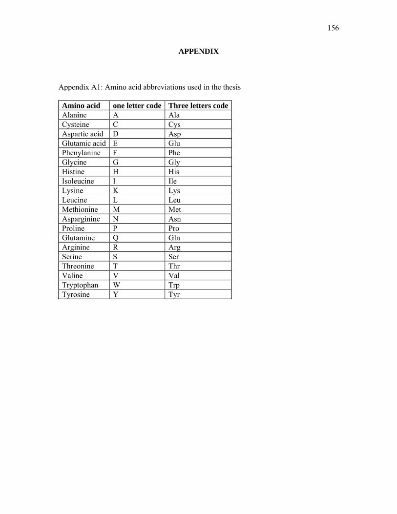
156
APPENDIX
Appendix A1: Amino acid abbreviations used in the thesis
Amino acid one letter code Three letters code Alanine A Ala Cysteine C Cys Aspartic acid D Asp Glutamic acid E Glu Phenylanine F Phe Glycine G Gly Histine H His Isoleucine I Ile Lysine K Lys Leucine L Leu Methionine M Met Asparginine N Asn Proline P Pro Glutamine Q Gln Arginine R Arg Serine S Ser Threonine T Thr Valine V Val Tryptophan W Trp Tyrosine Y Tyr
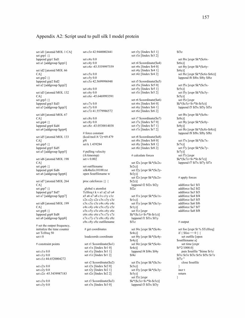
157
Appendix A2: Script used to pull silk I model protein
set id1 [atomid MOL 1 CA] set grp1 {} lappend grp1 $id1 set a1 [addgroup $grp1] set id2 [atomid MOL 66 CA] set grp2 {} lappend grp2 $id2 set a2 [addgroup $grp2] set id3 [atomid MOL 132 CA] set grp3 {} lappend grp3 $id3 set a3 [addgroup $grp3] set id4 [atomid MOL 67 CA] set grp4 {} lappend grp4 $id4 set a4 [addgroup $grp4] set id5 [atomid MOL 133 CA] set grp5 {} lappend grp5 $id5 set a5 [addgroup $grp5] set id6 [atomid MOL 198 CA] set grp6 {} lappend grp6 $id6 set a6 [addgroup $grp6] set id7 [atomid MOL 264 CA] set grp7 {} lappend grp7 $id7 set a7 [addgroup $grp7] set id8 [atomid MOL 199 CA] set grp8 {} lappend grp8 $id8 set a8 [addgroup $grp8] # set the output frequency, initialize the time counter set Tclfreq 50 set t 0 # constraint points set c1x 0.0 set c1y 0.0 set c1z 44.6520004272 set c2x 0.0 set c2y 0.0 set c2z -45.5439987183 set c3x 0.0 set c3y 0.0
set c3z 42.9440002441 set c4x 0.0 set c4y 0.0 set c4z -43.5559997559 set c5x 0.0 set c5y 0.0 set c5z 42.5699996948 set c6x 0.0 set c6y 0.0 set c6z -45.6469993591 set c7x 0.0 set c7y 0.0 set c7z 41.5579986572 set c8x 0.0 set c8y 0.0 set c8z -43.0530014038 # force constant (kcal/mol/A^2)=69.479 pN set k 1.439284 # pulling velocity (A/timestep) set v 0.002 set outfilename silk4helix10100.txt open $outfilename w proc calcforces {} { global x atomlist Tclfreq t k v a1 a2 a3 a4 a5 a6 a7 a8 c1x c1y c1z c2x c2y c2z c3x c3y c3z c3x c3y c3z c4x c4y c4z c4x c4y c4z c5x c5y c5z c5x c5y c5z c6x c6y c6z c6x c6y c6z c7x c7y c7z c7x c7y c7z c8x c8y c8z c8x c8y c8z outfilename # get coordinates loadcoords coordinate set r1 $coordinate($a1) set r1x [lindex $r1 0] set r1y [lindex $r1 1] set r1z [lindex $r1 2] set r2 $coordinate($a2) set r2x [lindex $r2 0] set r2y [lindex $r2 1] set r2z [lindex $r2 2] set r3 $coordinate($a3) set r3x [lindex $r3 0]
set r3y [lindex $r3 1] set r3z [lindex $r3 2] set r4 $coordinate($a4) set r4x [lindex $r4 0] set r4y [lindex $r4 1] set r4z [lindex $r4 2] set r5 $coordinate($a5) set r5x [lindex $r5 0] set r5y [lindex $r5 1] set r5z [lindex $r5 2] set r6 $coordinate($a6) set r6x [lindex $r6 0] set r6y [lindex $r6 1] set r6z [lindex $r6 2] set r7 $coordinate($a7) set r7x [lindex $r7 0] set r7y [lindex $r7 1] set r7z [lindex $r7 2] set r8 $coordinate($a8) set r8x [lindex $r8 0] set r8y [lindex $r8 1] set r8z [lindex $r8 2] # calculate forces set f2x [expr $k*($c2x-$r2x)] set f2y [expr $k*($c2y-$r2y)] set f2z [expr $k*($c2z-$r2z)] lappend f2 $f2x $f2y $f2z set f1x [expr $k*($c1x-$r1x)] set f1y [expr $k*($c1y-$r1y)] set f1z [expr $k*($c1z+$v*$t-$r1z)] lappend f1 $f1x $f1y $f1z set f4x [expr $k*($c4x-$r4x)] set f4y [expr $k*($c4y-$r4y)] set f4z [expr $k*($c4z-$r4z)] lappend f4 $f4x $f4y $f4z set f3x [expr $k*($c3x-$r3x)] set f3y [expr $k*($c3y-$r3y)] set f3z [expr $k*($c3z+$v*$t-$r3z)] lappend f3 $f3x $f3y
$f3z set f6x [expr $k*($c6x-$r6x)] set f6y [expr $k*($c6y-$r6y)] set f6z [expr $k*($c6z-$r6z)] lappend f6 $f6x $f6y $f6z set f5x [expr $k*($c5x-$r5x)] set f5y [expr $k*($c5y-$r5y)] set f5z [expr $k*($c5z+$v*$t-$r5z)] lappend f5 $f5x $f5y $f5z set f8x [expr $k*($c8x-$r8x)] set f8y [expr $k*($c8y-$r8y)] set f8z [expr $k*($c8z-$r8z)] lappend f8 $f8x $f8y $f8z set f7x [expr $k*($c7x-$r7x)] set f7y [expr $k*($c7y-$r7y)] set f7z [expr $k*($c7z+$v*$t-$r7z)] lappend f7 $f7x $f7y $f7z # apply forces addforce $a1 $f1 addforce $a2 $f2 addforce $a3 $f3 addforce $a4 $f4 addforce $a5 $f5 addforce $a6 $f6 addforce $a7 $f7 addforce $a8 $f8 # output set foo [expr $t % $Tclfreq] if { $foo == 0 } { set outfile [open $outfilename a] set time [expr $t*2/1000.0] puts $outfile "$time $r1z $f1z $r3z $f3z $r5z $f5z $r7z $f7z " close $outfile } incr t return }
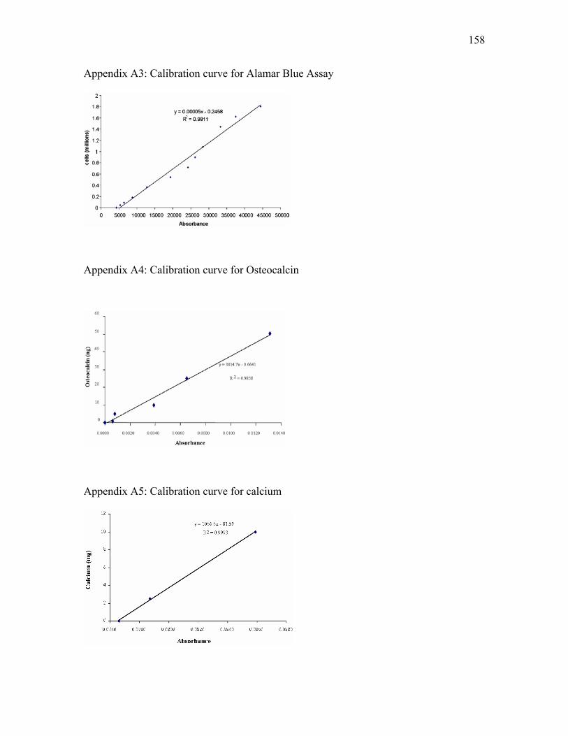
158
Appendix A3: Calibration curve for Alamar Blue Assay
Appendix A4: Calibration curve for Osteocalcin
Appendix A5: Calibration curve for calcium
159
VITA
Name Milind Ramesh Gandhi Education Ph.D.: Biomedical Engineering, Sciences and Health System Drexel University, Philadelphia, PA 19104, USA: December 2006 M.B.B.S. (Bachelor of Medicine and Bachelor of Surgery): General Physician (Medical doctor) Maharashtra Institute of Medical Sciences and Research, Latur, India: Jan 1998 Publications Book chapter: Ko, F. and Gandhi, M., Nanofibrous structures for tissue engineering scaffolds in Handbook of nanofiber and nanotechnology in textiles edited by Brown, P. and Stevens, K. Woodhead Publishing Limited, Abington Hall, Abington, Cambridge, CB1 6AH, UK (Under review) Patent pending: Ko, F.; Sukigara, S.; Gandhi, M.; Ayutsede, J., Electrospun carbon nanotube reinforced silk fibers. PCT/US2004/037076. Journal Articles:
1. Ayutsede, J.; Gandhi, M.; Sukigara, S.; Ye, H.; Hsu, C. M.; Gogotsi, Y.; Ko, F., Carbon Nanotube Reinforced Bombyx mori Silk Nanofibers by the Electrospinning Process. Biomacromolecules 2006, 7, (1), 208-214.
2. Li, M.; Mondrinos, M. J.; Gandhi, M. ; Ko, F. K.; Weiss, A. S.; Lelkes, P. I., Electrospun protein fibers as matrices for tissue engineering. Biomaterials 2005, 26, (30), 5999-6008.
3. Ayutsede, J.; Gandhi, M.; Sukigara, S.; Micklus, M.; Chen, H.-E.; Ko, F., Regeneration of Bombyx mori silk by electrospinning. Part 3: characterization of electrospun nonwoven mat. Polymer 2005, 46, (5), 1625-1634.
4. Sukigara, S.; Gandhi, M.; Ayutsede, J.; Micklus, M.; Ko, F., Regeneration of Bombyx mori silk by electrospinning. Part 2. Process optimization and empirical modeling using response surface methodology. Polymer 2004, 45, (11), 3701-3708.
5. Steplewski, A.; Ito, H.; Rucker, E.; Brittingham, R. J.; Alabyeva, T.; Gandhi, M.; Ko, F. K.; Birk, D. E.; Jimenez, S. A.; Fertala, A., Position of single amino acid substitutions in the collagen triple helix determines their effect on structure of collagen fibrils. Journal of Structural Biology 2004, 148, (3), 326-337.
6. Sukigara, S.; Gandhi, M.; Ayutsede, J.; Micklus, M.; Ko, F., Regeneration of Bombyx mori silk by electrospinning. Part 1: processing parameters and geometric properties. Polymer 2003, 44, (19), 5721-5727.


![Biomaterial Substrate-Mediated ... - download.xuebalib.comdownload.xuebalib.com/xuebalib.com.45057.pdf · and tissue engineering.[8–10] In this review, we will provide an overview](https://img.pdfslide.net/doc/110x75/603b249d392d225245386ffe/biomaterial-substrate-mediated-and-tissue-engineering8a10-in-this-review.jpg)