Embed Size (px)
Citation preview
Preface, Contents
Organization Blocks 1Common Parameters for SFCs 2Copy and Block Functions 3SFCs for Controlling Program Execution 4SFCs for Handling the System Clock 5SFCs for Handling Run-Time Meters 6SFCs for Transferring Data Records 7DPV1 SFBs According to PNO AK 1131 8SFCs for Handling Time-of-Day Interrupts 9SFCs for Handling Time-Delay Interrupts 10SFCs for Handling Synchronous Errors 11SFCs for Handling Interrupts andAsynchronous Errors 12SFCs for Diagnostics 13SFCs and SFBs for Updating the ProcessImage and Processing Bit Fields 14System Functions for Addressing Modules 15SFCs for Distributed I/Os 16SFCs for Global Data Communication 17Overview over the S7 Communication and theS7 Basic Communication 18S7 Communication 19Communication SFCs for Non-ConfiguredS7 Connections 20Generating Block-Related Messages 21IEC Timers and IEC Counters 22IEC Functions 23SFBs for Integrated Control 24SFBs for Compact CPUs 25SFCs for H CPUs 26Integrated Functions (for CPUs withIntegrated I/Os) 27Plastics Techology 28Diagnostic Data 29System Status Lists (SSL) 30
SIMATIC
System Softwarefor S7-300/400 Systemand Standard Functions
Reference Manual
This manual is part of the documentationpackage with the order number:6ES7810-4CA06-8BR0
Events 31Edition 12/2002A5E00171234-01
List of SFCs, and SFBs 32Bibliography, Glossary, Index
Copyright © Siemens AG 2002 All rights reserved
The reproduction, transmission or use of this document or itscontents is not permitted without express written authority.Offenders will be liable for damages. All rights, including rightscreated by patent grant or registration of a utility model or design,are reserved.
Siemens AGBereich Automatisierungs- und AntriebstechnikGeschaeftsgebiet Industrie-AutomatisierungssystemePostfach 4848, D- 90327 Nuernberg
Disclaimer of Liability
We have checked the contents of this manual for agreement withthe hardware and software described. Since deviations cannot beprecluded entirely, we cannot guarantee full agreement. However,the data in this manual are reviewed regularly and any necessarycorrections included in subsequent editions. Suggestions forimprovement are welcomed.
©Siemens AG 2002Technical data subject to change.
Siemens Aktiengesellschaft A5E00171234-01
Safety Guidelines
This manual contains notices intended to ensure personal safety, as well as to protect the products and
connected equipment against damage. These notices are highlighted by the symbols shown below and
graded according to severity by the following texts:
! Dangerindicates that death, severe personal injury or substantial property damage will result if properprecautions are not taken.
! Warningindicates that death, severe personal injury or substantial property damage can result if properprecautions are not taken.
! Cautionindicates that minor personal injury can result if proper precautions are not taken.
Cautionindicates that property damage can result if proper precautions are not taken.
Noticedraws your attention to particularly important information on the product, handling the product, or to aparticular part of the documentation.
Qualified Personnel
Only qualified personnel should be allowed to install and work on this equipment. Qualified persons are
defined as persons who are authorized to commission, to ground and to tag circuits, equipment, and
systems in accordance with established safety practices and standards.
Correct Usage
Note the following:
! WarningThis device and its components may only be used for the applications described in the catalog or the
technical description, and only in connection with devices or components from other manufacturers
which have been approved or recommended by Siemens.
This product can only function correctly and safely if it is transported, stored, set up, and installedcorrectly, and operated and maintained as recommended.
Trademarks
SIMATIC®, SIMATIC HMI® and SIMATIC NET® are registered trademarks of SIEMENS AG.
Third parties using for their own purposes any other names in this document which refer to trademarks might
infringe upon the rights of the trademark owners.
System Software for S7-300/400 System and Standard FunctionsA5E00171234-01 iii
Preface
Purpose
This manual provides you with a comprehensive overview of the organizationblocks (OB), system functions (SFC), system and standard function blocks (SFC),and IEC functions contained in the operating systems of the CPUs of the S7-300and S7-400. The appendix describes the diagnostic data, system status lists (SZL),and events.
Note
Refer to the reference section of the "S7-300 Programmable Controller, Hardwareand Installation" manual /70/ or the "S7-400/M7-400 Programmable ControllersModule Specifications" reference manual /101/ or the Instruction List: S7-400Programmable Controller /102/ (whichever version applies to your CPU) fordetails of which of these functions and blocks are available on which CPU. Theproperties of the CFBs and the S7 signaling functions for specific CPUs aredescribed in /70/ and /101/.
For information about the CPU operating systems, program design, and thecommunications and diagnostic capabilities of the CPUs, refer to the "ConfiguringHardware and Communication Connections STEP 7 V5.2" manual /234/ How tocall functions and function blocks in your program is explained in the languagedescriptions.
You program and assign parameters for all these functions using the STEP 7standard software. How to use this software is described in the "Programming withSTEP 7 V5.2" manual /231/ and in the STEP 7 online help.
Audience
This manual is intended for programmers and engineers who are familiar withcontrolling processes and are responsible for writing programs for programmablelogic controllers.
Preface
System Software for S7-300/400 System and Standard Functionsiv A5E00171234-01
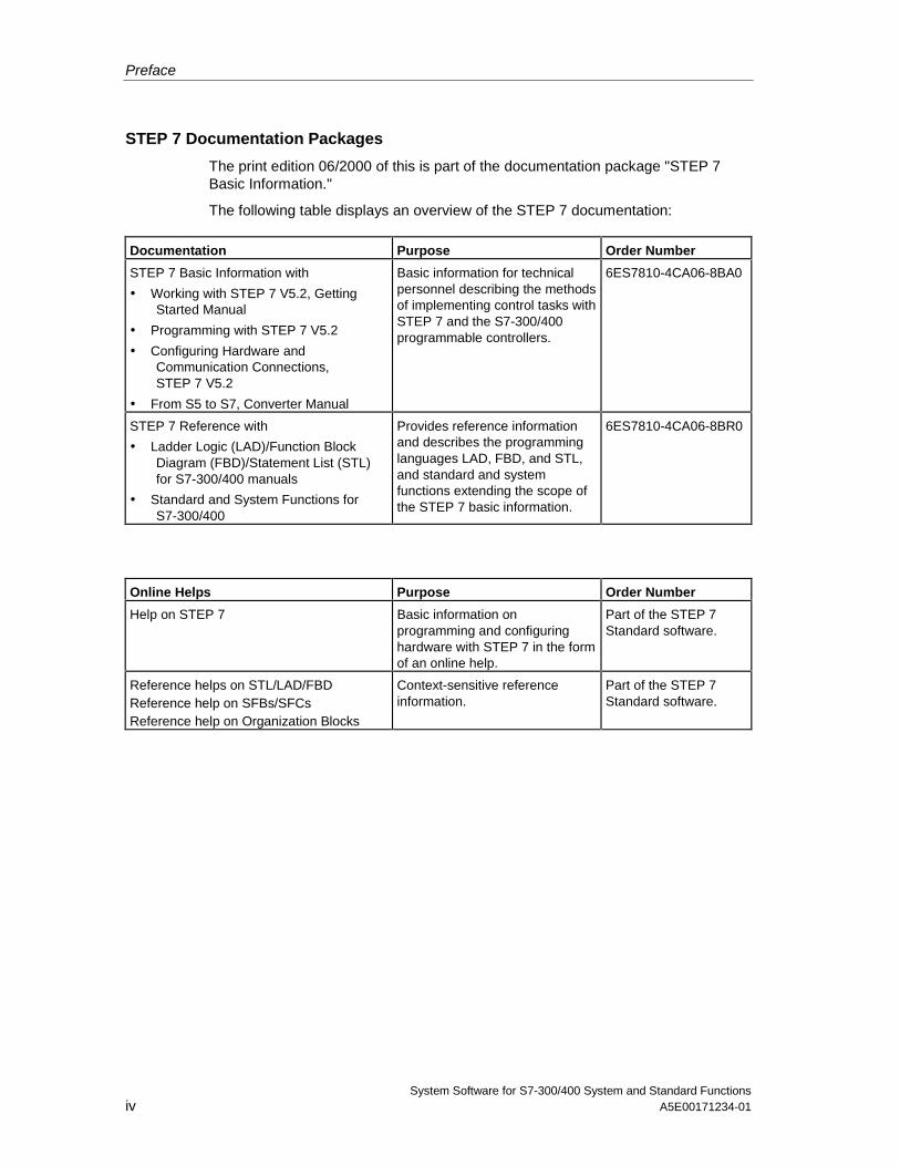
STEP 7 Documentation Packages
The print edition 06/2000 of this is part of the documentation package "STEP 7Basic Information."
The following table displays an overview of the STEP 7 documentation:
Documentation Purpose Order Number
STEP 7 Basic Information with
• Working with STEP 7 V5.2, GettingStarted Manual
• Programming with STEP 7 V5.2
• Configuring Hardware andCommunication Connections,STEP 7 V5.2
• From S5 to S7, Converter Manual
Basic information for technicalpersonnel describing the methodsof implementing control tasks withSTEP 7 and the S7-300/400programmable controllers.
6ES7810-4CA06-8BA0
STEP 7 Reference with
• Ladder Logic (LAD)/Function BlockDiagram (FBD)/Statement List (STL)for S7-300/400 manuals
• Standard and System Functions forS7-300/400
Provides reference informationand describes the programminglanguages LAD, FBD, and STL,and standard and systemfunctions extending the scope ofthe STEP 7 basic information.
6ES7810-4CA06-8BR0
Online Helps Purpose Order Number
Help on STEP 7 Basic information onprogramming and configuringhardware with STEP 7 in the formof an online help.
Part of the STEP 7Standard software.
Reference helps on STL/LAD/FBDReference help on SFBs/SFCsReference help on Organization Blocks
Context-sensitive referenceinformation.
Part of the STEP 7Standard software.
Preface
System Software for S7-300/400 System and Standard FunctionsA5E00171234-01 v
Online HelpThe manual is complemented by an online help which is integrated in the software.This online help is intended to provide you with detailed support when using thesoftware.
The help system is integrated in the software via a number of interfaces:
• There are several menu commands which you can select in the Help menu:The Contents command opens the index for the Help on STEP 7.
• Using Help provides detailed instructions on using the online help.
• The context-sensitive help offers information on the current context, forexample, an open dialog box or an active window. You can open the context-sensitive help by clicking the "Help" button or by pressing F1.
• The status bar offers another form of context-sensitive help. It displays a shortexplanation for each menu command when the mouse pointer is positioned onthe menu command.
• A brief explanation is also displayed for each icon in the toolbar when themouse pointer is positioned on the icon for a short time.
If you prefer to read the information from the online help in printed format, you canprint out individual help topics, books, or the entire online help.
This manual is an extract from the HTML-based Help on STEP 7. As the manualand the online help share an almost identical structure, it is easy to switch betweenthe manual and the online help.
Feedback on DocumentationTo help us to provide the best possible documentation for you and future STEP 7users, we need your support. If you have any comments or suggestions relating tothis manual or the online help, please complete the questionnaire at the end of themanual and send it to the address shown. Please include your own personal ratingof the documentation.
Other ManualsThe various S7-300 and S7-400 CPUs and the S7-300 and S7-400 modules aredescribed in the following manuals:
• For the S7-300 programmable logic controller, refer to the manuals:"S7 300 Programmable Controller, Hardware and Installation" /70/, "S7-300,M7-300 Programmable Controllers Module Specifications" /71/ and in theInstruction List /72/.
• For the S7-400 programmable logic controller, refer to the manual:"S7-400/M7-400 Programmable Controllers Module Specifications" /101/ and inthe Instruction List /102/.
Preface
System Software for S7-300/400 System and Standard Functionsvi A5E00171234-01
How to Use this Manual
This manual covers the following topics:
• Chapter 1 explains the functions of all the organization blocks.
• Chapter 2 describes the common parameters RET_VAL, REQ and BUSY.
• Chapters 3 to 28 describe the SFCs, SFBs and IEC-FCs.
• The Chapters sections 29 to 32 contain a description of the structure of thediagnostic data, an overview of the SZL-IDs, the possible events, lists of theSFCs, SFBs and FCs described in this manual, an overview of the SDBs.
• The bibliography contains a list of further manuals.
• The Glossary explains important terminology.
• The Index helps you to locate sections of text and topics quickly.
Conventions
References to other manuals and documentation are indicated by numbers inslashes /.../. These numbers refer to the titles of manuals listed in the bibliography.
Special Note
The system functions can be interrupted. If there are any restrictions that apply tocertain SFCs or situations, these are explained in the description of the particularSFC.
Documentation Reply FormIf you have comments about this manual or the online help, please fill out thequestionnaire at the end of this manual and send it the address shown. Please takethe time to add your own evaluation grade.
http://www.ad.siemens.de/partner
Training CentersSiemens offers a number of training courses to familiarize you with the SIMATICS7 automation system. Please contact your regional training center or our centraltraining center in D 90327 Nuremberg, Germany for details:Telephone: +49 (911) 895-3200.
http://www.sitrain.com/
Preface
System Software for S7-300/400 System and Standard FunctionsA5E00171234-01 vii
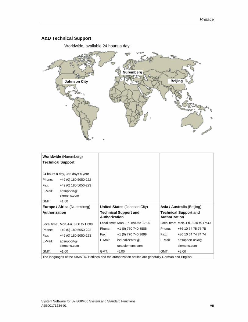
A&D Technical Support
Worldwide, available 24 hours a day:
Beijing
Nuremberg
Johnson City
Worldwide (Nuremberg)
Technical Support
24 hours a day, 365 days a year
Phone: +49 (0) 180 5050-222
Fax: +49 (0) 180 5050-223
E-Mail: [email protected]
GMT: +1:00
Europe / Africa (Nuremberg)
Authorization
Local time: Mon.-Fri. 8:00 to 17:00
Phone: +49 (0) 180 5050-222
Fax: +49 (0) 180 5050-223
E-Mail: [email protected]
GMT: +1:00
United States (Johnson City)
Technical Support andAuthorization
Local time: Mon.-Fri. 8:00 to 17:00
Phone: +1 (0) 770 740 3505
Fax: +1 (0) 770 740 3699
E-Mail: isd-callcenter@
sea.siemens.com
GMT: -5:00
Asia / Australia (Beijing)
Technical Support andAuthorization
Local time: Mon.-Fri. 8:30 to 17:30
Phone: +86 10 64 75 75 75
Fax: +86 10 64 74 74 74
E-Mail: adsupport.asia@
siemens.com
GMT: +8:00
The languages of the SIMATIC Hotlines and the authorization hotline are generally German and English.
Preface
System Software for S7-300/400 System and Standard Functionsviii A5E00171234-01
Service & Support on the InternetIn addition to our documentation, we offer our Know-how online on the internet at:
http://www.siemens.com/automation/service&support
where you will find the following:
• The newsletter, which constantly provides you with up-to-date information onyour products.
• The right documents via our Search function in Service & Support.
• A forum, where users and experts from all over the world exchange theirexperiences.
• Your local representative for Automation & Drives via our representativesdatabase.
• Information on field service, repairs, spare parts and more under "Services".
System Software for S7-300/400 System and Standard FunctionsA5E00171234-01 ix
Contents
1 Organization Blocks.......................................................................................................1-1
1.1 Overview of the Organization Blocks (OBs)......................................................1-11.2 Program Cycle Organization Block (OB1) ........................................................1-41.3 Time-of-Day Interrupt Organization Blocks (OB10 to OB17)...........................1-61.4 Time-Delay Interrupt Organization Blocks (OB20 to OB23) ..........................1-101.5 Cyclic Interrupt Organization Blocks (OB30 to OB38) ....................................1-121.6 Hardware Interrupt Organization Blocks (OB40 to OB47) ..............................1-141.7 Status Interrupt OB (OB 55)............................................................................1-161.8 Update Interrupt OB (OB 56) ..........................................................................1-171.9 Manufacturer Specific Interrupt OB (OB57) ....................................................1-181.10 Multicomputing Interrupt Organization Block (OB60) .....................................1-191.11 Synchronous Cycle Interrupt OBs (OB 61 to OB 64)......................................1-211.12 I/O Redundancy Error OB (OB70) ..................................................................1-221.13 CPU Redundancy Error OB (OB72) ...............................................................1-241.14 Communication Redundancy Error OB (OB73) ..............................................1-271.15 Time Error Organization Block (OB80) ...........................................................1-281.16 Power Supply Error Organization Block (OB81) .............................................1-311.17 Diagnostic Interrupt Organization Block (OB82) .............................................1-331.18 Insert / Remove Module Interrupt Organization Block (OB83) .......................1-351.19 CPU Hardware Fault Organization Block (OB84) ...........................................1-381.20 Priority Class Error Organization Block (OB85) ..............................................1-391.21 Rack Failure Organization Block (OB86) ........................................................1-431.22 Communication Error Organization Block (OB87) ..........................................1-471.23 Processing Interrupt OB (OB 88) ....................................................................1-491.24 Background Organization Block (OB90) .........................................................1-501.25 Startup Organization Blocks (OB100, OB101 and OB102) ............................1-521.26 Programming Error Organization Block (OB121)............................................1-571.27 I/O Access Error Organization Block (OB122)................................................1-60
2 Common Parameters for SFCs .....................................................................................2-1
2.1 Evaluating Errors with Output Parameter RET_VAL ........................................2-12.2 Meaning of the Parameters REQ, RET_VAL and BUSY
with Asynchronous SFCs ..................................................................................2-6
Contents
System Software for S7-300/400 System and Standard Functionsx A5E00171234-01
3 Copy and Block Functions ............................................................................................3-1
3.1 Copying Variables with SFC 20 "BLKMOV"......................................................3-13.2 Uninterruptible Copying of Variables with SFC 81 "UBLKMOV" ......................3-33.3 Initializing a Memory Area with SFC 21 "FILL" .................................................3-53.4 Creating a Data Block with SFC 22 "CREAT_DB"............................................3-73.5 Deleting a Data Block with SFC 23 "DEL_DB" .................................................3-93.6 Testing a Data Block with SFC 24 "TEST_DB" ..............................................3-113.7 Compressing the User Memory with SFC 25 "COMPRESS" .........................3-123.8 Transferring a Substitute Value to Accumulator 1
with SFC 44 "REPL_VAL"...............................................................................3-143.9 Generating Data Blocks in Load Memory with SFC 82 "CREA_DBL"............3-153.10 Reading from a Data Block In Load Memory with SFC 83 "READ_DBL".......3-183.11 Writing a Data Block in Load Memory with SFC 84 "WRIT_DBL" ..................3-20
4 SFCs for Controlling Program Execution ....................................................................4-1
4.1 Re-triggering Cycle Time Monitoring with SFC 43 "RE_TRIGR"......................4-14.2 Changing the CPU to STOP with SFC 46 "STP" ..............................................4-14.3 Delaying Execution of the User Program with SFC 47 "WAIT" ........................4-24.4 Triggering a Multicomputing Interrupt with SFC 35 "MP_ALM" ........................4-34.5 Controlling CiR with SFC 104 "CiR"..................................................................4-4
5 SFCs for Handling the System Clock ...........................................................................5-1
5.1 Setting the TOD with SFC 0 "SET_CLK" ..........................................................5-15.2 Reading the Time with SFC 1 "READ_CLK" ....................................................5-25.3 Synchronizing Slave Clocks with SFC 48 "SNC_RTCB"..................................5-35.4 Setting the Time-of-Day and the TOD Status with SFC 100 "SET_CLKS" ......5-4
6 SFCs for Handling Run-Time Meters............................................................................6-1
6.1 Runtime Meters .................................................................................................6-16.2 Handling Runtime meters with SFC 101 "RTM" ...............................................6-26.3 Setting the Runtime Meter with SFC 2 "SET_RTM" .........................................6-46.4 Starting and Stopping a Run-time Meter with SFC 3 "CTRL_RTM" .................6-56.5 Reading a Runtime Meter with SFC 4 "READ_RTM" .......................................6-66.6 Reading the System Time with SFC 64 "TIME_TCK".......................................6-7
7 SFCs for Transferring Data Records ............................................................................7-1
7.1 Writing and Reading Data Records...................................................................7-17.2 Reading Defined Parameters with SFC 54 "RD_DPARM" ...............................7-37.3 Reading Predefined Parameters with SFC 102 "RD_DPARA".........................7-47.4 Writing Dynamic Parameters with SFC 55 "WR_PARM"..................................7-57.5 Writing Default Parameters with SFC 56 "WR_DPARM"..................................7-77.6 Assigning Parameters to a Module with SFC 57 "PARM_MOD"......................7-87.7 Writing a Data Record with SFC 58 "WR_REC".............................................7-117.8 Reading a Data Record with SFC 59 "RD_REC" ...........................................7-127.9 Further Error Information for SFCs 55 to 59 ...................................................7-17
8 DPV1 SFBs According to PNO AK 1131.......................................................................8-1
8.1 Reading a Data Record from a DP Slave with SFB 52 "RDREC" ....................8-18.2 Writing a Data Record in a DP Slave with SFB53 "WRREC" ...........................8-38.3 Receiving an Interrupt from a DP Slave with SFB 54 "RALRM".......................8-58.4 Sending an Interrupt to the DP Master with SFB 75 "SALRM".......................8-14
Contents
System Software for S7-300/400 System and Standard FunctionsA5E00171234-01 xi
9 SFCs for Handling Time-of-Day Interrupts ..................................................................9-1
9.1 Handling Time-of-Day Interrupts .......................................................................9-19.2 Characteristics of SFCs 28 to 31 ......................................................................9-29.3 Setting a Time-of-Day Interrupt with SFC 28 "SET_TINT" ...............................9-49.4 Canceling a Time-of-Day Interrupt with SFC 29 "CAN_TINT"..........................9-59.5 Activating a Time-of-Day Interrupt with SFC 30 "ACT_TINT"...........................9-69.6 Querying a Time-of-Day Interrupt with SFC 31 "QRY_TINT" ...........................9-7
10 SFCs for Handling Time-Delay Interrupts ..................................................................10-1
10.1 Handling Time-Delay Interrupts ......................................................................10-110.2 Starting a Time-Delay Interrupt with SFC 32 "SRT_DINT".............................10-310.3 Querying a Time-Delay Interrupt with SFC 34 "QRY_DINT" ..........................10-410.4 Canceling a Time-Delay Interrupt with SFC 33 "CAN_DINT".........................10-5
11 SFCs for Handling Synchronous Errors ....................................................................11-1
11.1 Masking Synchronous Errors ..........................................................................11-111.2 Masking Synchronous Errors with SFC 36 "MSK_FLT" .................................11-911.3 Unmasking Synchronous Errors with SFC 37 "DMSK_FLT" ........................11-1011.4 Reading the Error Register with SFC 38 "READ_ERR" ...............................11-11
12 SFCs for Handling Interrupts and Asynchronous Errors.........................................12-1
12.1 Delaying and Disabling Interrupt and Asynchronous Errors ...........................12-112.2 Disabling the Processing of New Interrupts and
Asynchronous Errors with SFC 39 "DIS_IRT" ................................................12-312.3 Enabling the Processing of New Interrupts and
Asynchronous Errors with SFC 40 "EN_IRT" .................................................12-512.4 Delaying the Processing of Higher Priority Interrupts and
Asynchronous Errors with SFC 41 "DIS_AIRT" ..............................................12-612.5 Enabling the Processing of Higher Priority Interrupts and
Asynchronous Errors with SFC 42 "EN_AIRT" ...............................................12-7
13 SFCs for Diagnostics ...................................................................................................13-1
13.1 System Diagnostics.........................................................................................13-113.2 Reading OB Start Information with SFC 6 "RD_SINFO" ................................13-113.3 Reading a System Status List or Partial List with SFC 51 "RDSYSST" .........13-413.4 Writing a User-Defined Diagnostic Event to the Diagnostic Buffer
with SFC 52 "WR_USMSG"..........................................................................13-1013.5 Determining the OB Program Runtime with SFC 78 "OB_RT".....................13-1413.6 Diagnosis of the Current Connection Status with SFC 87 "C_DIAG"...........13-1713.7 Identifying the Bus Topology of a DP Master System with SFC 103
"DP_TOPOL".................................................................................................13-22
14 SFCs and SFBs for Updating the Process Image and Processing Bit Fields ........14-1
14.1 Updating the Process Image Input Table with SFC 26 "UPDAT_PI"..............14-114.2 Updating the Process Image Output Table with SFC 27 "UPDAT_PO".........14-314.3 Updating the Process Image Partition Input Table in a
Synchronous Cycle with SFC 126 "SYNC_PI" ...............................................14-414.4 Updating the Process Image Partition Output Table in a
Synchronous Cycle with SFC 127 "SYNC_PO"..............................................14-614.5 Setting a Bit Field in the I/O Area with SFC 79 "SET" ....................................14-814.6 Resetting a Bit Field in the I/O Area with SFC 80 "RSET"..............................14-914.7 Implementing a Sequencer with SFB 32 "DRUM" ........................................14-10
Contents
System Software for S7-300/400 System and Standard Functionsxii A5E00171234-01
15 System Functions for Addressing Modules ..............................................................15-1
15.1 Querying the Logical Base Address of a Modulewith SFC 5 "GADR_LGC" ...............................................................................15-1
15.2 Querying the Module Slot Belonging to a Logical Addresswith SFC 49 "LGC_GADR" .............................................................................15-2
15.3 Querying all Logical Addresses of a Module with SFC 50 "RD_LGADR".......15-4
16 SFCs for Distributed I/Os.............................................................................................16-1
16.1 Triggering a Hardware Interrupt on the DP Master with SFC 7 "DP_PRAL" ..16-116.2 Synchronizing Groups of DP Slaves with SFC 11 "DPSYC_FR" ...................16-316.3 Deactivating and Activating DP Slaves with SFC 12 "D_ACT_DP"..............16-1016.4 Reading Diagnostic Data of a DP Slave with SFC 13 "DPNRM_DG"
(Slave Diagnostics) .......................................................................................16-1516.5 Reading Consistent Data of a DP Standard Slave
with SFC 14 "DPRD_DAT"............................................................................16-1916.6 Writing Consistent Data to a DP Standard Slave
with SFC 15 "DPWR_DAT"...........................................................................16-21
17 SFCs for Global Data Communication .......................................................................17-1
17.1 Sending a GD Packet with SFC 60 "GD_SND" ..............................................17-117.2 Programmed Acceptance of a Received GD Packet
with SFC 61 "GD_RCV" ..................................................................................17-3
18 Overview over the S7 Communication and the S7 Basic Communication.............18-1
18.1 Differences between the Blocks of the S7 Communication and theS7 Basic Communication ................................................................................18-1
18.2 Data Consistency ............................................................................................18-318.3 Overview of the S7 Communication Blocks ....................................................18-518.4 Overview of the Blocks for the S7 Basic Communication...............................18-8
19 S7 Communication .......................................................................................................19-1
19.1 Common Parameters of the SFBs/FBs and SFCs/FCsfor S7 Communication.....................................................................................19-1
19.2 Startup Routine of SFBs for Configured S7 Connections...............................19-519.3 How SFBs React to Problems.........................................................................19-719.4 Uncoordinated Sending of Data with SFB 8/FB 8 "USEND"...........................19-919.5 Uncoordinated Receiving of Data with SFB/FB 9 "URCV" ...........................19-1219.6 Sending Segmented Data with SFB/FB 12 "BSEND"...................................19-1519.7 Receiving Segmented Data with SFB/FB 13 "BRCV"...................................19-1819.8 Writing Data to a Remote CPU with SFB/FB 15 "PUT" ................................19-2219.9 Read Data from a Remote CPU with SFB/FB 14 "GET" ..............................19-2519.10 Sending Data to a Printer with SFB 16 "PRINT"...........................................19-2819.11 Initiating a Warm or Cold Restart on a Remote Device
with SFB 19 "START" ...................................................................................19-3419.12 Changing a Remote Device to the STOP State with SFB 20 "STOP"..........19-3619.13 Initiating a Hot Restart on a Remote Device with SFB 21 "RESUME" .........19-3819.14 Querying the Status of a Remote Partner with SFB 22 "STATUS" ..............19-4019.15 Receiving the Status of a Remote Device with SFB 23 "USTATUS" ...........19-4219.16 Querying the Status of the Connection Belonging to an SFB Instance
with SFC 62 "CONTROL" .............................................................................19-4519.17 Querying the Connection Status with FC 62 "C_CNTRL".............................19-4719.18 Work Memory Requirements of the S7 Communication SFBs/FBs .............19-48
Contents
System Software for S7-300/400 System and Standard FunctionsA5E00171234-01 xiii
20 Communication SFCs for Non-Configured S7 Connections ...................................20-1
20.1 Common Parameters of the Communication SFCs........................................20-120.2 Error Information of the Communication SFCs for Non-Configured
S7 Connections...............................................................................................20-320.3 Sending Data to a Communication Partner outside the Local S7 Station
with SFC 65 "X_SEND"...................................................................................20-720.4 Receiving Data from a Communication Partner outside the
Local S7 Station with SFC 66 "X_RCV"..........................................................20-920.5 Writing Data to a Communication Partner outside the Local S7 Station
with SFC 68 "X_PUT" ...................................................................................20-1320.6 Reading Data from a Communication Partner outside the
Local S7 Station with SFC 67 "X_GET"........................................................20-1520.7 Aborting an Existing Connection to a Communication Partner outside the
Local S7 Station with SFC 69 "X_ABORT"...................................................20-1720.8 Writing Data to a Communication Partner within the Local S7 Station
with SFC 73 "I_PUT".....................................................................................20-1820.9 Reading Data from a Communication Partner within the Local S7 Station
with SFC 72 "I_GET".....................................................................................20-2020.10 Aborting an Existing Connection to a Communication Partner
within the Local S7 Station with SFC 74 "I_ABORT"....................................20-22
21 Generating Block-Related Messages .........................................................................21-1
21.1 Introduction to Generating Block-Related Messages with SFBs ....................21-121.2 Generating Block-Related Messages without Acknowledgment
with SFB 36 "NOTIFY" ....................................................................................21-521.3 Generating Block Related Messages without Acknowledgement Display
with SFB 31 "NOTIFY_8P"..............................................................................21-721.4 Generating Block-Related Messages with Acknowledgment
with SFB 33 "ALARM"...................................................................................21-1021.5 Generating Block-Related Messages with Associated Values
for Eight Signals with SFB 35 "ALARM_8P" .................................................21-1321.6 Generating Block-Related Messages without Associated Values
for Eight Signals with SFB 34 "ALARM_8" ...................................................21-1621.7 Sending Archive Data with SFB 37 "AR_SEND" ..........................................21-1821.8 Disabling Block-Related, Symbol-Related and Group Status Messages
with SFC 10 "DIS_MSG"...............................................................................21-2021.9 Enabling Block-Related, Symbol-Related, and Group Status Messages
with SFC 9 "EN_MSG"..................................................................................21-2221.10 Startup Behavior of the SFBs for Generating Block-Related Messages ......21-2421.11 How the SFBs for Generating Block-Related Messages React
to Problems ...................................................................................................21-2421.12 Introduction to Generating Block-Related Messages with SFCs..................21-2521.13 Generating Acknowledgeable Block-Related Messages with SFC 17
"ALARM_SQ" and Permanently Acknowledged Block-Related Messageswith SFC 18 "ALARM_S" ..............................................................................21-28
21.14 Querying the Acknowledgment Status of the Last ALARM_SQ/ALARM_DQEntering Event Message with SFC 19 "ALARM_SC" ...................................21-31
21.15 Generating Acknowledgeable and Permanently Acknowledged Block RelatedMessages with SFCs 107 "ALARM_DQ" and 108 "ALARM_D" ...................21-32
21.16 Reading Dynamic System Resources with SFC 105 "READ_SI".................21-3421.17 Reading Dynamic System Resources with SFC 106 "DEL_SI"....................21-37
Contents
System Software for S7-300/400 System and Standard Functionsxiv A5E00171234-01
22 IEC Timers and IEC Counters......................................................................................22-1
22.1 Generating a Pulse with SFB 3 "TP"...............................................................22-122.2 Generating an On Delay with SFB 4 "TON"....................................................22-322.3 Generating an Off Delay with SFB 5 "TOF" ....................................................22-522.4 Counting Up with SFB 0 "CTU".......................................................................22-722.5 Counting Down with SFB 1 "CTD" ..................................................................22-822.6 Up / Down Count with SFB 2 "CTUD".............................................................22-9
23 IEC Functions................................................................................................................23-1
23.1 Overview .........................................................................................................23-123.2 Technical Data of the IEC Functions...............................................................23-323.3 Date and Time as Complex Data Types .........................................................23-523.4 Time-of-Day Functions....................................................................................23-623.5 Comparing DATE_AND_TIME Variables......................................................23-1023.6 Comparing STRING Variables ......................................................................23-1323.7 Editing Number Values .................................................................................23-1623.8 Example in STL.............................................................................................23-1723.9 Example in STL.............................................................................................23-1823.10 Editing STRING Variables.............................................................................23-1923.11 Converting Data Type Formats .....................................................................23-24
24 SFBs for Integrated Control ........................................................................................24-1
24.1 Continuous Control with SFB 41/FB 41 "CONT_C"........................................24-124.2 Step Control with SFB 42/FB 42 "CONT_S"...................................................24-924.3 Pulse Generation with SFB 43/FB 43 "PULSEGEN" ....................................24-1524.4 Example of the PULSEGEN Block................................................................24-25
25 SFBs for Compact CPUs..............................................................................................25-1
25.1 Positioning With Analog Output Using SFB 44 "Analog" ................................25-125.2 Positioning with Digital Output Using SFB 46 "DIGITAL" .............................25-1325.3 Controlling the Counter with SFB 47 "COUNT" ............................................25-2425.4 Controlling the Frequency Measurement with SFB 48 "FREQUENC" .........25-2925.5 Controlling Pulse Width Modulation with SFB 49 "PULSE" ..........................25-3325.6 Sending Data (ASCII, 3964(R)) with SFB 60 "SEND_PTP" .........................25-3625.7 Receiving Data (ASCII, 3964(R)) with SFB 61 "RCV_PTP" .........................25-3925.8 Deleting the Receive Buffer (ASCII, 3964(R)) with SFB 62 "RES_RCVB"...25-4225.9 Sending Data (512(R)) with SFB 63 "SEND_RK".........................................25-4425.10 Fetching Data (RK 512) with SFB 64 "FETCH RK" ......................................25-4825.11 Receiving and Providing Data (RK 512) with SFB 65 "SERVE_RK"............25-5325.12 Additional Error Information of the SFBs 60 to 65 ........................................25-58
26 SFCs for H CPUs...........................................................................................................26-1
26.1 Controlling Operation in H Systems with SFC 90 "H_CTRL"..........................26-1
27 Integrated Functions (for CPUs with integrated I/Os)...............................................27-1
27.1 SFB 29 (HS_COUNT) .....................................................................................27-127.2 SFB 30 (FREQ_MES) .....................................................................................27-227.3 SFB 38 (HSC_A_B) ........................................................................................27-327.4 SFB 39 (POS) .................................................................................................27-4
28 Plastics Techology .......................................................................................................28-1
28.1 SFC 63 (AB_CALL) .........................................................................................28-1
Contents
System Software for S7-300/400 System and Standard FunctionsA5E00171234-01 xv
29 Diagnostic Data.............................................................................................................29-1
29.1 Overview of the Structure of Diagnostic Data .................................................29-129.2 Diagnostic Data...............................................................................................29-229.3 Structure of Channel-Specific Diagnostic Data...............................................29-4
30 System Status Lists (SSL) ...........................................................................................30-1
30.1 Overview of the System Status Lists (SSL) ....................................................30-130.2 Structure of a Partial SSL List .........................................................................30-330.3 SSL-ID.............................................................................................................30-430.4 Possible Partial System Status Lists...............................................................30-530.5 SSL-ID W#16#xy11 - Module Identification ....................................................30-630.6 SSL-ID W#16#xy12 - CPU Characteristics.....................................................30-730.7 SSL-ID W#16#xy13 - Memory Areas............................................................30-1030.8 SSL-ID W#16#xy14 - System Areas.............................................................30-1130.9 SSL-ID W#16#xy15 - Block Types................................................................30-1330.10 SSL-ID W#16#xy19 - Status of the Module LEDs ........................................30-1430.11 SSL-ID W#16#xy1C - Component Identification...........................................30-1630.12 SSL-ID W#16#xy22 - Interrupt Status...........................................................30-1930.13 SSL ID W#16#xy25 - Assigning Process Images Partitions to the OBs.......30-2130.14 SSL-ID W#16#xy32 - Communication Status Data ......................................30-2430.15 Data Record of the Partial List Extract with SSL-ID W#16#0132
Index W#16#0005 .........................................................................................30-2530.16 Data Record of the Partial List Extract with SSL-ID W#16#0132
Index W#16#0008 .........................................................................................30-2630.17 Data Record of the Partial List Extract with SSL-ID W#16#0132
Index W#16#000B.........................................................................................30-2830.18 Data Record of the Partial List Extract with SSL-ID W#16#0132
Index W#16#000C ........................................................................................30-2930.19 Data Record of the Partial List Extract with SSL-ID W#16#0232
Index W#16#0004 .........................................................................................30-3030.20 SSL-ID W#16#xy71 - H CPU Group Information ..........................................30-3130.21 SSL-ID W#16#xy74 - Status of the Module LEDs ........................................30-3430.22 SSL-ID W#16#xy75 - Switched DP Slaves in the H System ........................30-3630.23 SSL-ID W#16#xy90 - DP Master System Information ..................................30-3830.24 SSL-ID W#16#xy91 - Module Status Information .........................................30-4030.25 SSL-ID W#16#xy92 - Rack / Station Status Information ..............................30-4430.26 SSL-ID W#16#xy95 - Extended DP Master System Information..................30-4830.27 SSL-ID W#16#xyA0 - Diagnostic Buffer .......................................................30-5030.28 SSL-ID W#16#00B1 - Module Diagnostic Information..................................30-5130.29 SSL-ID W#16#00B2 - Diagnostic Data Record 1 with Physical Address .....30-5330.30 SSL-ID W#16#00B3 - Module Diagnostic Data with Logical Base Address.30-5430.31 SSL-ID W#16#00B4 - Diagnostic Data of a DP Slave..................................30-55
Contents
System Software for S7-300/400 System and Standard Functionsxvi A5E00171234-01
31 Events ............................................................................................................................31-1
31.1 Events and Event ID .......................................................................................31-131.2 Event Class 1 - Standard OB Events ..............................................................31-231.3 Event Class 2 - Synchronous Errors ...............................................................31-331.4 Event Class 3 - Asynchronous Errors .............................................................31-431.5 Event Class 4 - Stop Events and Other Mode Changes.................................31-631.6 Event Class 5 - Mode Run-time Events ..........................................................31-931.7 Event Class 6 - Communication Events........................................................31-1031.8 Event Class 7 - H/F Events ...........................................................................31-1131.9 Event Class 8 - Diagnostic Events for Modules ............................................31-1331.10 Event Class 9 - Standard User Events .........................................................31-1531.11 Event Classes A and B - Free User Events ..................................................31-1731.12 Reserved Event Classes...............................................................................31-17
32 List of SFCs, and SFBs ................................................................................................32-1
32.1 List of SFCs, Sorted Numerically ....................................................................32-132.2 List of SFCs, Sorted Alphabetically.................................................................32-432.3 List of SFBs, Sorted Numerically ....................................................................32-732.4 List of SFBs, Sorted Alphabetically.................................................................32-9
Bibliography
Glossary
Index
System Software for S7-300/400 System and Standard FunctionsA5E00171234-01 1-1
1 Organization Blocks
1.1 Overview of the Organization Blocks (OBs)
What Are Organization Blocks?
Organization Blocks (OBs) are the interface between the operating system of theCPU and the user program. OBs are used to execute specific program sections:
• At the startup of the CPU
• In a cyclic or clocked execution
• Whenever errors occur
• Whenever hardware interrupts occur.
Organization blocks are executed according to the priority they are allocated.
Which OBs Are Available?
Not all CPUs can process all of the OBs available in STEP 7. Refer to Operationslists /72/ and /102/ to determine which OBs are included with your CPU.
Organization Blocks
System Software for S7-300/400 System and Standard Functions1-2 A5E00171234-01
Where to Find More Information?
Refer to the online help and the following manuals for more information:
• /70/: this manual contains the technical data that describe the capabilities ofthe different S7-300 CPUs.
• /101/: this manual contains the technical data that describe the capabilities ofthe different S7-400 CPUs.
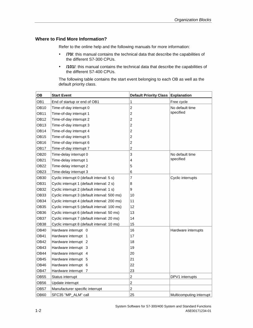
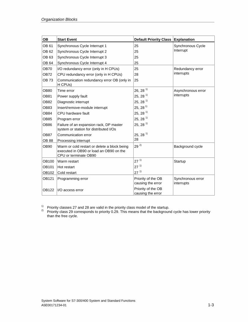
The following table contains the start event belonging to each OB as well as thedefault priority class.
OB Start Event Default Priority Class Explanation
OB1 End of startup or end of OB1 1 Free cycle
OB10
OB11
OB12
OB13
OB14
OB15
OB16
OB17
Time-of-day interrupt 0
Time-of-day interrupt 1
Time-of-day interrupt 2
Time-of-day interrupt 3
Time-of-day interrupt 4
Time-of-day interrupt 5
Time-of-day interrupt 6
Time-of-day interrupt 7
2
2
2
2
2
2
2
2
No default timespecified
OB20
OB21
OB22
OB23
Time-delay interrupt 0
Time-delay interrupt 1
Time-delay interrupt 2
Time-delay interrupt 3
3
4
5
6
No default timespecified
OB30
OB31
OB32
OB33
OB34
OB35
OB36
OB37
OB38
Cyclic interrupt 0 (default interval: 5 s)
Cyclic interrupt 1 (default interval: 2 s)
Cyclic interrupt 2 (default interval: 1 s)
Cyclic interrupt 3 (default interval: 500 ms)
Cyclic interrupt 4 (default interval: 200 ms)
Cyclic interrupt 5 (default interval: 100 ms)
Cyclic interrupt 6 (default interval: 50 ms)
Cyclic interrupt 7 (default interval: 20 ms)
Cyclic interrupt 8 (default interval: 10 ms)
7
8
9
10
11
12
13
14
15
Cyclic interrupts
OB40
OB41
OB42
OB43
OB44
OB45
OB46
OB47
Hardware interrupt 0
Hardware interrupt 1
Hardware interrupt 2
Hardware interrupt 3
Hardware interrupt 4
Hardware interrupt 5
Hardware interrupt 6
Hardware interrupt 7
16
17
18
19
20
21
22
23
Hardware interrupts
OB55 Status interrupt 2 DPV1 interrupts
OB56 Update interrupt 2
OB57 Manufacturer specific interrupt 2
OB60 SFC35 "MP_ALM" call 25 Multicomputing interrupt
Organization Blocks
System Software for S7-300/400 System and Standard FunctionsA5E00171234-01 1-3
OB Start Event Default Priority Class Explanation
OB 61
OB 62
OB 63
OB 64
Synchronous Cycle Interrupt 1
Synchronous Cycle Interrupt 2
Synchronous Cycle Interrupt 3
Synchronous Cycle Interrupt 4
25
25
25
25
Synchronous CycleInterrupt
OB70
OB72
OB 73
I/O redundancy error (only in H CPUs)
CPU redundancy error (only in H CPUs)
Communication redundancy error OB (only inH CPUs)
25
28
25
Redundancy errorinterrupts
OB80
OB81
OB82
OB83
OB84
OB85
OB86
OB87
OB 88
Time error
Power supply fault
Diagnostic interrupt
Insert/remove-module interrupt
CPU hardware fault
Program error
Failure of an expansion rack, DP mastersystem or station for distributed I/Os
Communication error
Processing interrupt
26, 28 1)
25, 28 1)
25, 28 1)
25, 28 1)
25, 28 1)
25, 28 1)
25, 28 1)
25, 28 1)
28
Asynchronous errorinterrupts
OB90 Warm or cold restart or delete a block beingexecuted in OB90 or load an OB90 on theCPU or terminate OB90
29 2) Background cycle
OB100
OB101
OB102
Warm restart
Hot restart
Cold restart
27 1)
27 1)
27 1)
Startup
OB121
OB122
Programming error
I/O access error
Priority of the OBcausing the error
Priority of the OBcausing the error
Synchronous errorinterrupts
1) Priority classes 27 and 28 are valid in the priority class model of the startup.2) Priority class 29 corresponds to priority 0.29. This means that the background cycle has lower priority
than the free cycle.
Organization Blocks
System Software for S7-300/400 System and Standard Functions1-4 A5E00171234-01
1.2 Program Cycle Organization Block (OB1)
Description
The operating system of the S7 CPU executes OB1 periodically. When OB1 hasbeen executed, the operating system starts it again. Cyclic execution of OB1 isstarted after the startup has been completed. You can call other function blocks(FBs, SFBs) or functions (FCs, SFCs) in OB1.
Understanding the Operation of OB1
OB1 has the lowest priority of all of the OBs whose run-times are monitored, inother words, all of the other OBs except OB90 can interrupt the execution of OB1.The following events cause the operating system to call OB1:
• The startup is completed.
• The execution of OB1 (the previous cycle) has finished.
When OB1 has been executed, the operating system sends global data. Beforerestarting OB1, the operating system writes the process-image output table to theoutput modules, updates the process-image input table and receives any globaldata for the CPU.
S7 monitors the maximum scan time, ensuring a maximum response time. Thevalue for the maximum scan time is preset to 150 ms. You can set a new value oryou can restart the time monitoring anywhere within your program with SFC43"RE_TRIGR." If your program exceeds the maximum cycle time for OB1, theoperating system calls OB80 (time error OB); if OB80 is not programmed, the CPUchanges to the STOP mode.
Apart from monitoring the maximum scan time, it is also possible to guarantee aminimum scan time. The operating system will delay the start of a new cycle(writing of the process image output table to the output modules) until the minimumscan time has been reached.
Refer to the manuals /70/ and /101/ for the ranges of the parameters "maximum"and "minimum" scan time. You change parameter settings using STEP 7.
Organization Blocks
System Software for S7-300/400 System and Standard FunctionsA5E00171234-01 1-5
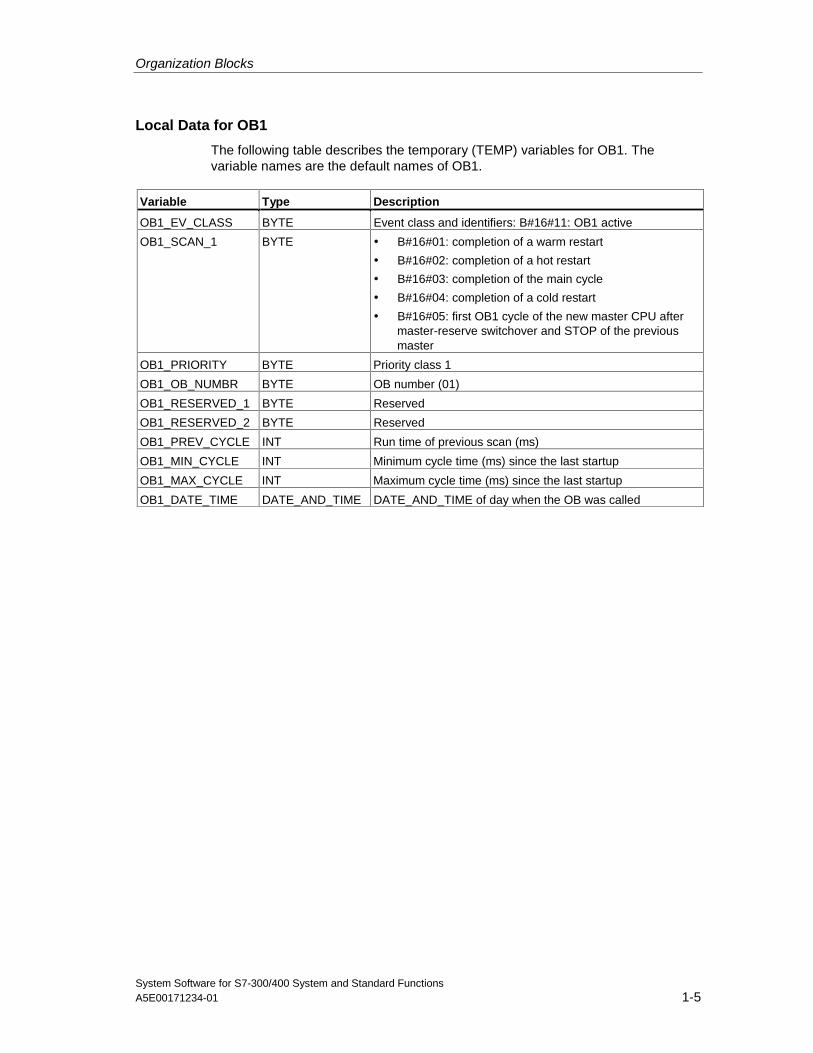
Local Data for OB1
The following table describes the temporary (TEMP) variables for OB1. Thevariable names are the default names of OB1.
Variable Type Description
OB1_EV_CLASS BYTE Event class and identifiers: B#16#11: OB1 active
OB1_SCAN_1 BYTE • B#16#01: completion of a warm restart
• B#16#02: completion of a hot restart
• B#16#03: completion of the main cycle
• B#16#04: completion of a cold restart
• B#16#05: first OB1 cycle of the new master CPU aftermaster-reserve switchover and STOP of the previousmaster
OB1_PRIORITY BYTE Priority class 1
OB1_OB_NUMBR BYTE OB number (01)
OB1_RESERVED_1 BYTE Reserved
OB1_RESERVED_2 BYTE Reserved
OB1_PREV_CYCLE INT Run time of previous scan (ms)
OB1_MIN_CYCLE INT Minimum cycle time (ms) since the last startup
OB1_MAX_CYCLE INT Maximum cycle time (ms) since the last startup
OB1_DATE_TIME DATE_AND_TIME DATE_AND_TIME of day when the OB was called
Organization Blocks
System Software for S7-300/400 System and Standard Functions1-6 A5E00171234-01
1.3 Time-of-Day Interrupt Organization Blocks(OB10 to OB17)
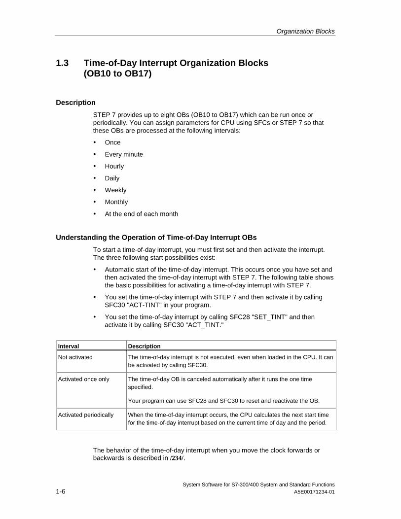
Description
STEP 7 provides up to eight OBs (OB10 to OB17) which can be run once orperiodically. You can assign parameters for CPU using SFCs or STEP 7 so thatthese OBs are processed at the following intervals:
• Once
• Every minute
• Hourly
• Daily
• Weekly
• Monthly
• At the end of each month
Understanding the Operation of Time-of-Day Interrupt OBs
To start a time-of-day interrupt, you must first set and then activate the interrupt.The three following start possibilities exist:
• Automatic start of the time-of-day interrupt. This occurs once you have set andthen activated the time-of-day interrupt with STEP 7. The following table showsthe basic possibilities for activating a time-of-day interrupt with STEP 7.
• You set the time-of-day interrupt with STEP 7 and then activate it by callingSFC30 "ACT-TINT" in your program.
• You set the time-of-day interrupt by calling SFC28 "SET_TINT" and thenactivate it by calling SFC30 "ACT_TINT."
Interval Description
Not activated The time-of-day interrupt is not executed, even when loaded in the CPU. It canbe activated by calling SFC30.
Activated once only The time-of-day OB is canceled automatically after it runs the one timespecified.
Your program can use SFC28 and SFC30 to reset and reactivate the OB.
Activated periodically When the time-of-day interrupt occurs, the CPU calculates the next start timefor the time-of-day interrupt based on the current time of day and the period.
The behavior of the time-of-day interrupt when you move the clock forwards orbackwards is described in /234/.
Organization Blocks
System Software for S7-300/400 System and Standard FunctionsA5E00171234-01 1-7
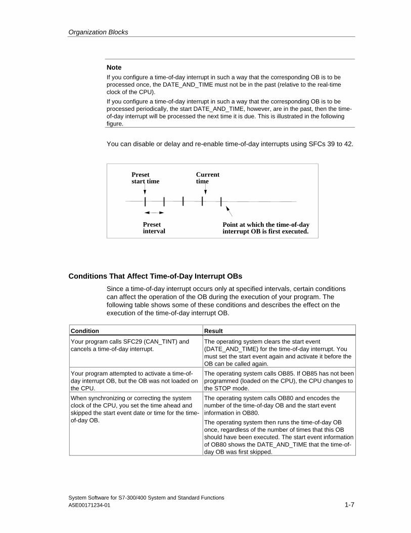
NoteIf you configure a time-of-day interrupt in such a way that the corresponding OB is to beprocessed once, the DATE_AND_TIME must not be in the past (relative to the real-timeclock of the CPU).
If you configure a time-of-day interrupt in such a way that the corresponding OB is to beprocessed periodically, the start DATE_AND_TIME, however, are in the past, then the time-of-day interrupt will be processed the next time it is due. This is illustrated in the followingfigure.
You can disable or delay and re-enable time-of-day interrupts using SFCs 39 to 42.
Presetstart time
Currenttime
Presetinterval
Point at which the time-of-dayinterrupt OB is first executed.
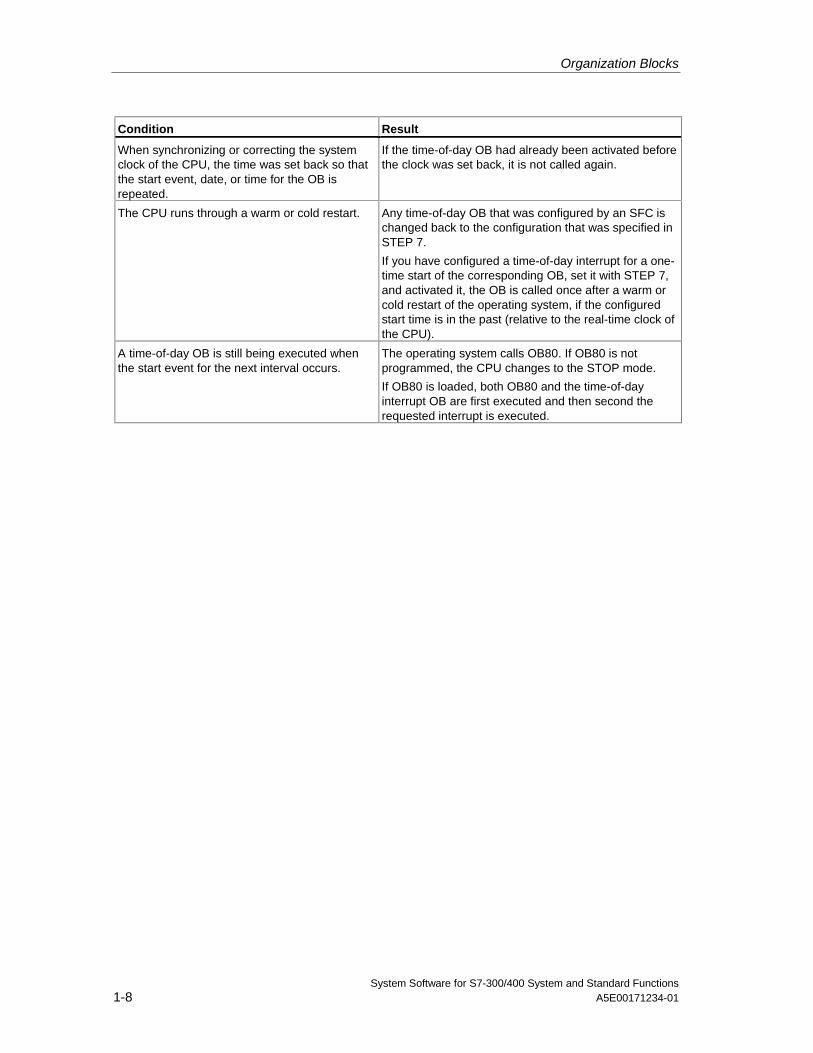
Conditions That Affect Time-of-Day Interrupt OBs
Since a time-of-day interrupt occurs only at specified intervals, certain conditionscan affect the operation of the OB during the execution of your program. Thefollowing table shows some of these conditions and describes the effect on theexecution of the time-of-day interrupt OB.
Condition Result
Your program calls SFC29 (CAN_TINT) andcancels a time-of-day interrupt.
The operating system clears the start event(DATE_AND_TIME) for the time-of-day interrupt. Youmust set the start event again and activate it before theOB can be called again.
Your program attempted to activate a time-of-day interrupt OB, but the OB was not loaded onthe CPU.
The operating system calls OB85. If OB85 has not beenprogrammed (loaded on the CPU), the CPU changes tothe STOP mode.
When synchronizing or correcting the systemclock of the CPU, you set the time ahead andskipped the start event date or time for the time-of-day OB.
The operating system calls OB80 and encodes thenumber of the time-of-day OB and the start eventinformation in OB80.
The operating system then runs the time-of-day OBonce, regardless of the number of times that this OBshould have been executed. The start event informationof OB80 shows the DATE_AND_TIME that the time-of-day OB was first skipped.
Organization Blocks
System Software for S7-300/400 System and Standard Functions1-8 A5E00171234-01
Condition Result
When synchronizing or correcting the systemclock of the CPU, the time was set back so thatthe start event, date, or time for the OB isrepeated.
If the time-of-day OB had already been activated beforethe clock was set back, it is not called again.
The CPU runs through a warm or cold restart. Any time-of-day OB that was configured by an SFC ischanged back to the configuration that was specified inSTEP 7.
If you have configured a time-of-day interrupt for a one-time start of the corresponding OB, set it with STEP 7,and activated it, the OB is called once after a warm orcold restart of the operating system, if the configuredstart time is in the past (relative to the real-time clock ofthe CPU).
A time-of-day OB is still being executed whenthe start event for the next interval occurs.
The operating system calls OB80. If OB80 is notprogrammed, the CPU changes to the STOP mode.
If OB80 is loaded, both OB80 and the time-of-dayinterrupt OB are first executed and then second therequested interrupt is executed.
Organization Blocks
System Software for S7-300/400 System and Standard FunctionsA5E00171234-01 1-9
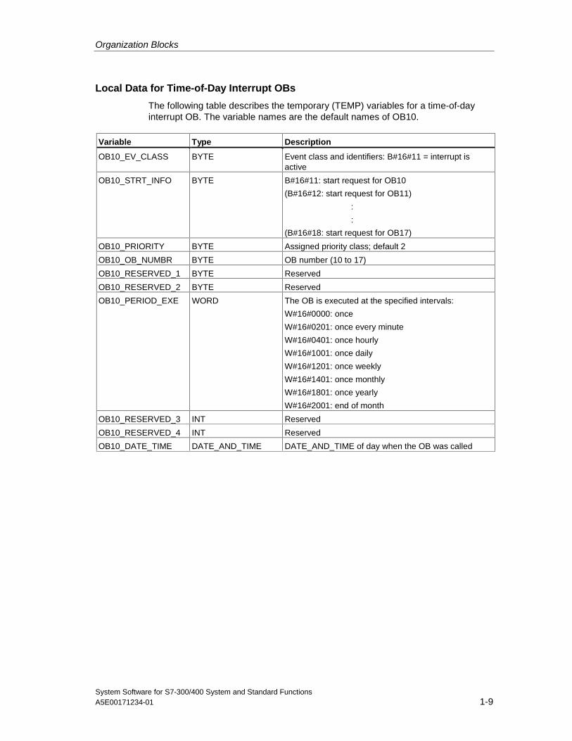
Local Data for Time-of-Day Interrupt OBs
The following table describes the temporary (TEMP) variables for a time-of-dayinterrupt OB. The variable names are the default names of OB10.
Variable Type Description
OB10_EV_CLASS BYTE Event class and identifiers: B#16#11 = interrupt isactive
OB10_STRT_INFO BYTE B#16#11: start request for OB10
(B#16#12: start request for OB11)
:
:
(B#16#18: start request for OB17)
OB10_PRIORITY BYTE Assigned priority class; default 2
OB10_OB_NUMBR BYTE OB number (10 to 17)
OB10_RESERVED_1 BYTE Reserved
OB10_RESERVED_2 BYTE Reserved
OB10_PERIOD_EXE WORD The OB is executed at the specified intervals:
W#16#0000: once
W#16#0201: once every minute
W#16#0401: once hourly
W#16#1001: once daily
W#16#1201: once weekly
W#16#1401: once monthly
W#16#1801: once yearly
W#16#2001: end of month
OB10_RESERVED_3 INT Reserved
OB10_RESERVED_4 INT Reserved
OB10_DATE_TIME DATE_AND_TIME DATE_AND_TIME of day when the OB was called
Organization Blocks
System Software for S7-300/400 System and Standard Functions1-10 A5E00171234-01
1.4 Time-Delay Interrupt Organization Blocks(OB20 to OB23)
Description
S7 provides up to four OBs (OB20 to OB23) which are executed after a specifieddelay. Every time-delay OB is started by calling SFC32 (SRT_DINT). The delaytime is an input parameter of the SFC.
When your program calls SFC32 (SRT_DINT), you provide the OB number, thedelay time, and a user-specific identifier. After the specified delay, the OB starts.You can also cancel the execution of a time-delay interrupt that has not yet started.
Understanding the Operation of Time-Delay Interrupt OBs
After the delay time has expired (value in milliseconds transferred to SFC32together with an OB number), the operating system starts the corresponding OB.
To use the time-delay interrupts, you must perform the following tasks:
• You must call SFC32 (SRT_DINT).
• You must download the time-delay interrupt OB to the CPU as part of yourprogram.
Time-delay OBs are executed only when the CPU is in the RUN mode. A warm ora cold restart clears any start events for the time-delay OBs. If a time-delayinterrupt has not started, you can use SFC33 (CAN_DINT) to cancel its execution.
The delay time has a resolution of 1 ms. A delay time that has expired can bestarted again immediately. You can query the status of a delay-time interrupt usingSFC34 (QRY_DINT).
The operating system calls an asynchronous error OB if one of the following eventsoccur:
• If the operating system attempts to start an OB that is not loaded and youspecified its number when calling SFC32 "SRT_DINT."
• If the next start event for a time-delay interrupt occurs before the time-delayOB has been completely executed.
You can disable or delay and re-enable delay interrupts using SFCs 39 to 42.
Organization Blocks
System Software for S7-300/400 System and Standard FunctionsA5E00171234-01 1-11
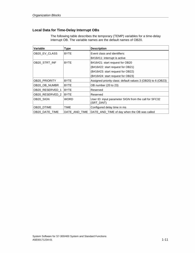
Local Data for Time-Delay Interrupt OBs
The following table describes the temporary (TEMP) variables for a time-delayinterrupt OB. The variable names are the default names of OB20.
Variable Type Description
OB20_EV_CLASS BYTE Event class and identifiers:
B#16#11: interrupt is active
OB20_STRT_INF BYTE B#16#21: start request for OB20
(B#16#22: start request for OB21)
(B#16#23: start request for OB22)
(B#16#24: start request for OB23)
OB20_PRIORITY BYTE Assigned priority class: default values 3 (OB20) to 6 (OB23)
OB20_OB_NUMBR BYTE OB number (20 to 23)
OB20_RESERVED_1 BYTE Reserved
OB20_RESERVED_2 BYTE Reserved
OB20_SIGN WORD User ID: input parameter SIGN from the call for SFC32(SRT_DINT)
OB20_DTIME TIME Configured delay time in ms
OB20_DATE_TIME DATE_AND_TIME DATE_AND_TIME of day when the OB was called
Organization Blocks
System Software for S7-300/400 System and Standard Functions1-12 A5E00171234-01
1.5 Cyclic Interrupt Organization Blocks (OB30 to OB38)
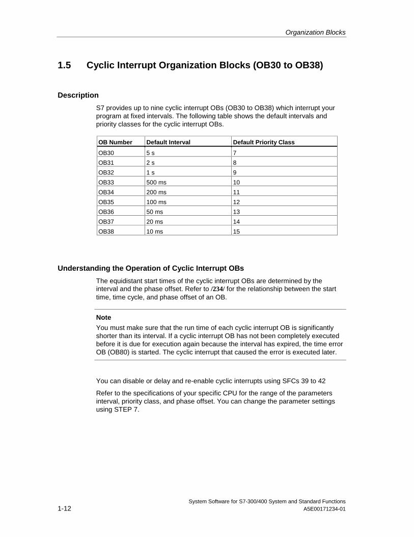
Description
S7 provides up to nine cyclic interrupt OBs (OB30 to OB38) which interrupt yourprogram at fixed intervals. The following table shows the default intervals andpriority classes for the cyclic interrupt OBs.
OB Number Default Interval Default Priority Class
OB30 5 s 7
OB31 2 s 8
OB32 1 s 9
OB33 500 ms 10
OB34 200 ms 11
OB35 100 ms 12
OB36 50 ms 13
OB37 20 ms 14
OB38 10 ms 15
Understanding the Operation of Cyclic Interrupt OBs
The equidistant start times of the cyclic interrupt OBs are determined by theinterval and the phase offset. Refer to /234/ for the relationship between the starttime, time cycle, and phase offset of an OB.
Note
You must make sure that the run time of each cyclic interrupt OB is significantlyshorter than its interval. If a cyclic interrupt OB has not been completely executedbefore it is due for execution again because the interval has expired, the time errorOB (OB80) is started. The cyclic interrupt that caused the error is executed later.
You can disable or delay and re-enable cyclic interrupts using SFCs 39 to 42
Refer to the specifications of your specific CPU for the range of the parametersinterval, priority class, and phase offset. You can change the parameter settingsusing STEP 7.
Organization Blocks
System Software for S7-300/400 System and Standard FunctionsA5E00171234-01 1-13
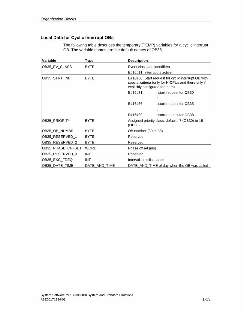
Local Data for Cyclic Interrupt OBs
The following table describes the temporary (TEMP) variables for a cyclic interruptOB. The variable names are the default names of OB35.
Variable Type Description
OB35_EV_CLASS BYTE Event class and identifiers
B#16#11: interrupt is active
OB35_STRT_INF BYTE B#16#30: Start request for cyclic interrupt OB withspecial criteria (only for H-CPUs and there only ifexplicitly configured for them)
B#16#31 : start request for OB30
:
B#16#36 : start request for OB35
:
B#16#39 : start request for OB38
OB35_PRIORITY BYTE Assigned priority class: defaults 7 (OB30) to 15(OB38)
OB35_OB_NUMBR BYTE OB number (30 to 38)
OB35_RESERVED_1 BYTE Reserved
OB35_RESERVED_2 BYTE Reserved
OB35_PHASE_OFFSET WORD Phase offset [ms]
OB35_RESERVED_3 INT Reserved
OB35_EXC_FREQ INT Interval in milliseconds
OB35_DATE_TIME DATE_AND_TIME DATE_AND_TIME of day when the OB was called
Organization Blocks
System Software for S7-300/400 System and Standard Functions1-14 A5E00171234-01
1.6 Hardware Interrupt Organization Blocks (OB40 to OB47)
Description
S7 provides up to eight independent hardware interrupts each with its own OB.
By assigning parameters with STEP 7, you specify the following for each signalmodule that will trigger hardware interrupts:
• Which channels trigger a hardware interrupt under what conditions.
• Which hardware interrupt OB is assigned to the individual groups of channels(as default, all hardware interrupts are processed by OB40).
With CPs and FMs, you assign these parameters using their own software.
You select the priority classes for the individual hardware interrupt OBs usingSTEP 7.
Understanding the Operation of Hardware Interrupt OBs
After a hardware interrupt has been triggered by the module, the operating systemidentifies the slot and the corresponding hardware interrupt OB. If this OB has ahigher priority than the currently active priority class, it will be started. The channel-specific acknowledgement is sent after this hardware interrupt OB has beenexecuted.
If another event that triggers a hardware interrupt occurs on the same moduleduring the time between identification and acknowledgement of a hardwareinterrupt, the following applies:
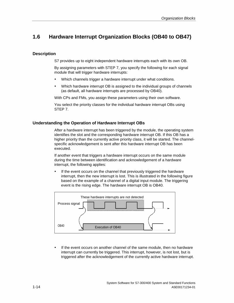
• If the event occurs on the channel that previously triggered the hardwareinterrupt, then the new interrupt is lost. This is illustrated in the following figurebased on the example of a channel of a digital input module. The triggeringevent is the rising edge. The hardware interrupt OB is OB40.
Process signal
OB40 Execution of OB40
These hardware interrupts are not detected
• If the event occurs on another channel of the same module, then no hardwareinterrupt can currently be triggered. This interrupt, however, is not lost, but istriggered after the acknowledgement of the currently active hardware interrupt.
Organization Blocks
System Software for S7-300/400 System and Standard FunctionsA5E00171234-01 1-15
If a hardware interrupt is triggered and its OB is currently active due to a hardwareinterrupt from another module, the new request is recorded and the OB processedwhen it is free.
You can disable or delay and re-enable hardware interrupts using SFCs 39 to 42.
You can assign parameters for the hardware interrupts of a module not only withSTEP 7 but also with SFCs 55 to 57.
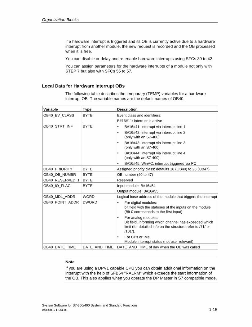
Local Data for Hardware Interrupt OBs
The following table describes the temporary (TEMP) variables for a hardwareinterrupt OB. The variable names are the default names of OB40.
Variable Type Description
OB40_EV_CLASS BYTE Event class and identifiers:
B#16#11: interrupt is active
OB40_STRT_INF BYTE • B#16#41: interrupt via interrupt line 1
• B#16#42: interrupt via interrupt line 2(only with an S7-400)
• B#16#43: interrupt via interrupt line 3(only with an S7-400)
• B#16#44: interrupt via interrupt line 4(only with an S7-400)
• B#16#45: WinAC: interrupt triggered via PC
OB40_PRIORITY BYTE Assigned priority class: defaults 16 (OB40) to 23 (OB47)
OB40_OB_NUMBR BYTE OB number (40 to 47)
OB40_RESERVED_1 BYTE Reserved
OB40_IO_FLAG BYTE Input module: B#16#54
Output module: B#16#55
OB40_MDL_ADDR WORD Logical base address of the module that triggers the interrupt
OB40_POINT_ADDR DWORD • For digital modules:bit field with the statuses of the inputs on the module(Bit 0 corresponds to the first input)
• For analog modules:Bit field, informing which channel has exceeded whichlimit (for detailed info on the structure refer to /71/ or/101/).
• For CPs or IMs:Module interrupt status (not user relevant)
OB40_DATE_TIME DATE_AND_TIME DATE_AND_TIME of day when the OB was called
Note
If you are using a DPV1 capable CPU you can obtain additional information on theinterrupt with the help of SFB54 "RALRM" which exceeds the start information ofthe OB. This also applies when you operate the DP Master in S7 compatible mode.
Organization Blocks
System Software for S7-300/400 System and Standard Functions1-16 A5E00171234-01
1.7 Status Interrupt OB (OB 55)
Note
A status interrupt OB (OB 55) is only available for DPV1 capable CPUs.
Description
The CPU operating system calls OB55 if a status interrupt was triggered via theslot of a DPV1 slave. This might be the case if a component (module or rack) of aDPV1 slaves changes its operating mode, for example from RUN to STOP. Forprecise information on events that trigger a status interrupt, refer to thedocumentation of the DPV1 slave‘s manufacturer.
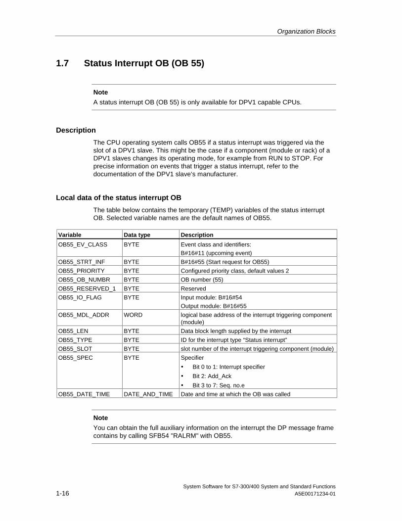
Local data of the status interrupt OB
The table below contains the temporary (TEMP) variables of the status interruptOB. Selected variable names are the default names of OB55.
Variable Data type Description
OB55_EV_CLASS BYTE Event class and identifiers:B#16#11 (upcoming event)
OB55_STRT_INF BYTE B#16#55 (Start request for OB55)
OB55_PRIORITY BYTE Configured priority class, default values 2
OB55_OB_NUMBR BYTE OB number (55)
OB55_RESERVED_1 BYTE Reserved
OB55_IO_FLAG BYTE Input module: B#16#54
Output module: B#16#55
OB55_MDL_ADDR WORD logical base address of the interrupt triggering component(module)
OB55_LEN BYTE Data block length supplied by the interrupt
OB55_TYPE BYTE ID for the interrupt type “Status interrupt”
OB55_SLOT BYTE slot number of the interrupt triggering component (module)
OB55_SPEC BYTE Specifier
• Bit 0 to 1: Interrupt specifier
• Bit 2: Add_Ack
• Bit 3 to 7: Seq. no.e
OB55_DATE_TIME DATE_AND_TIME Date and time at which the OB was called
Note
You can obtain the full auxiliary information on the interrupt the DP message framecontains by calling SFB54 "RALRM" with OB55.
Organization Blocks
System Software for S7-300/400 System and Standard FunctionsA5E00171234-01 1-17
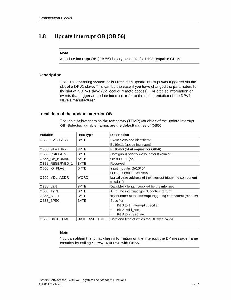
1.8 Update Interrupt OB (OB 56)
Note
A update interrupt OB (OB 56) is only available for DPV1 capable CPUs.
Description
The CPU operating system calls OB56 if an update interrupt was triggered via theslot of a DPV1 slave. This can be the case if you have changed the parameters forthe slot of a DPV1 slave (via local or remote access). For precise information onevents that trigger an update interrupt, refer to the documentation of the DPV1slave‘s manufacturer.
Local data of the update interrupt OB
The table below contains the temporary (TEMP) variables of the update interruptOB. Selected variable names are the default names of OB56.
Variable Data type Description
OB56_EV_CLASS BYTE Event class and identifiers:B#16#11 (upcoming event)
OB56_STRT_INF BYTE B#16#56 (Start request for OB56)OB56_PRIORITY BYTE Configured priority class, default values 2OB56_OB_NUMBR BYTE OB number (56)OB56_RESERVED_1 BYTE ReservedOB56_IO_FLAG BYTE Input module: B#16#54
Output module: B#16#55OB56_MDL_ADDR WORD logical base address of the interrupt triggering component
(module)OB56_LEN BYTE Data block length supplied by the interruptOB56_TYPE BYTE ID for the interrupt type “Update interrupt”OB56_SLOT BYTE slot number of the interrupt triggering component (module)OB56_SPEC BYTE Specifier
• Bit 0 to 1: Interrupt specifier• Bit 2: Add_Ack• Bit 3 to 7: Seq. no.
OB56_DATE_TIME DATE_AND_TIME Date and time at which the OB was called
Note
You can obtain the full auxiliary information on the interrupt the DP message framecontains by calling SFB54 "RALRM" with OB55.
Organization Blocks
System Software for S7-300/400 System and Standard Functions1-18 A5E00171234-01
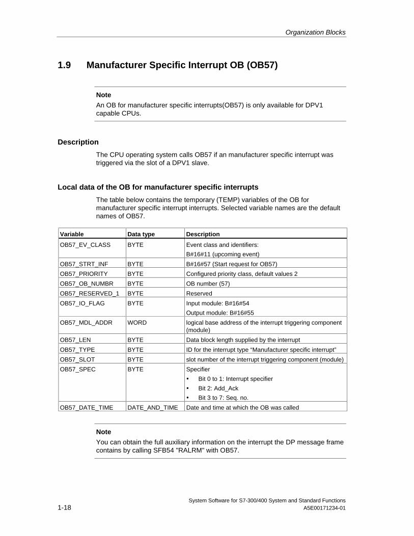
1.9 Manufacturer Specific Interrupt OB (OB57)
Note
An OB for manufacturer specific interrupts(OB57) is only available for DPV1capable CPUs.
Description
The CPU operating system calls OB57 if an manufacturer specific interrupt wastriggered via the slot of a DPV1 slave.
Local data of the OB for manufacturer specific interrupts
The table below contains the temporary (TEMP) variables of the OB formanufacturer specific interrupt interrupts. Selected variable names are the defaultnames of OB57.
Variable Data type Description
OB57_EV_CLASS BYTE Event class and identifiers:
B#16#11 (upcoming event)
OB57_STRT_INF BYTE B#16#57 (Start request for OB57)
OB57_PRIORITY BYTE Configured priority class, default values 2
OB57_OB_NUMBR BYTE OB number (57)
OB57_RESERVED_1 BYTE Reserved
OB57_IO_FLAG BYTE Input module: B#16#54
Output module: B#16#55
OB57_MDL_ADDR WORD logical base address of the interrupt triggering component(module)
OB57_LEN BYTE Data block length supplied by the interrupt
OB57_TYPE BYTE ID for the interrupt type “Manufacturer specific interrupt”
OB57_SLOT BYTE slot number of the interrupt triggering component (module)
OB57_SPEC BYTE Specifier
• Bit 0 to 1: Interrupt specifier
• Bit 2: Add_Ack
• Bit 3 to 7: Seq. no.
OB57_DATE_TIME DATE_AND_TIME Date and time at which the OB was called
Note
You can obtain the full auxiliary information on the interrupt the DP message framecontains by calling SFB54 "RALRM" with OB57.
Organization Blocks
System Software for S7-300/400 System and Standard FunctionsA5E00171234-01 1-19
1.10 Multicomputing Interrupt Organization Block (OB60)
Description
Using the multicomputing interrupt, you can make sure that the reaction of theCPUs is synchronized to an event during multicomputing. In contrast to hardwareinterrupts triggered by signal modules, the multicomputing interrupt can only beoutput by CPUs.
Understanding the Operation of Multicomputing Interrupt OBs
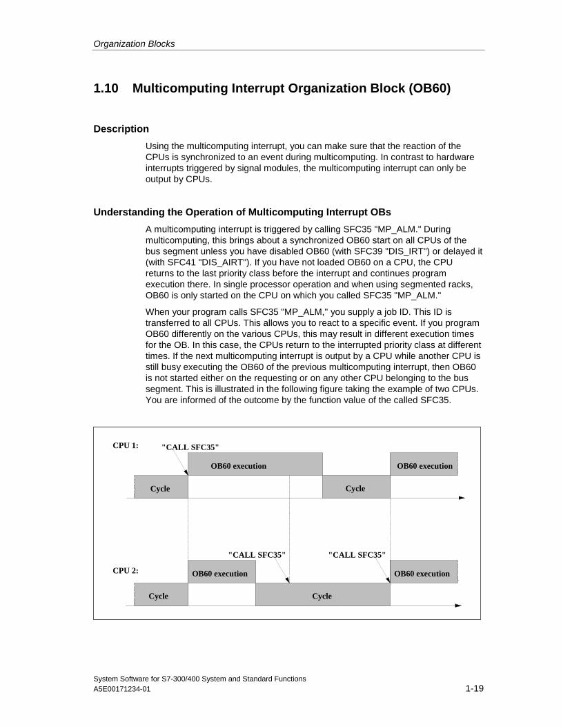
A multicomputing interrupt is triggered by calling SFC35 "MP_ALM." Duringmulticomputing, this brings about a synchronized OB60 start on all CPUs of thebus segment unless you have disabled OB60 (with SFC39 "DIS_IRT") or delayed it(with SFC41 "DIS_AIRT"). If you have not loaded OB60 on a CPU, the CPUreturns to the last priority class before the interrupt and continues programexecution there. In single processor operation and when using segmented racks,OB60 is only started on the CPU on which you called SFC35 "MP_ALM."
When your program calls SFC35 "MP_ALM," you supply a job ID. This ID istransferred to all CPUs. This allows you to react to a specific event. If you programOB60 differently on the various CPUs, this may result in different execution timesfor the OB. In this case, the CPUs return to the interrupted priority class at differenttimes. If the next multicomputing interrupt is output by a CPU while another CPU isstill busy executing the OB60 of the previous multicomputing interrupt, then OB60is not started either on the requesting or on any other CPU belonging to the bussegment. This is illustrated in the following figure taking the example of two CPUs.You are informed of the outcome by the function value of the called SFC35.
CPU 1:
CPU 2:
Cycle
OB60 execution
OB60 execution OB60 execution
Cycle
OB60 execution
Cycle
Cycle
"CALL SFC35"
"CALL SFC35" "CALL SFC35"
Organization Blocks
System Software for S7-300/400 System and Standard Functions1-20 A5E00171234-01
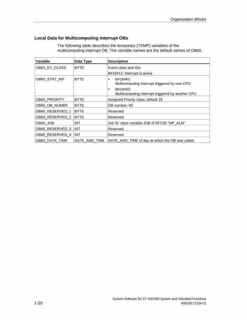
Local Data for Multicomputing Interrupt OBs
The following table describes the temporary (TEMP) variables of themulticomputing interrupt OB. The variable names are the default names of OB60.
Variable Data Type Description
OB60_EV_CLASS BYTE Event class and IDs:
B#16#11: Interrupt is active
OB60_STRT_INF BYTE • B#16#61:Multicomputing interrupt triggered by own CPU
• B#16#62:Multicomputing interrupt triggered by another CPU
OB60_PRIORITY BYTE Assigned Priority class: default 25
OB60_OB_NUMBR BYTE OB number: 60
OB60_RESERVED_1 BYTE Reserved
OB60_RESERVED_2 BYTE Reserved
OB60_JOB INT Job ID: input variable JOB of SFC35 "MP_ALM"
OB60_RESERVED_3 INT Reserved
OB60_RESERVED_4 INT Reserved
OB60_DATE_TIME DATE_AND_TIME DATE_AND_TIME of day at which the OB was called.
Organization Blocks
System Software for S7-300/400 System and Standard FunctionsA5E00171234-01 1-21
1.11 Synchronous Cycle Interrupt OBs (OB 61 to OB 64)
Description
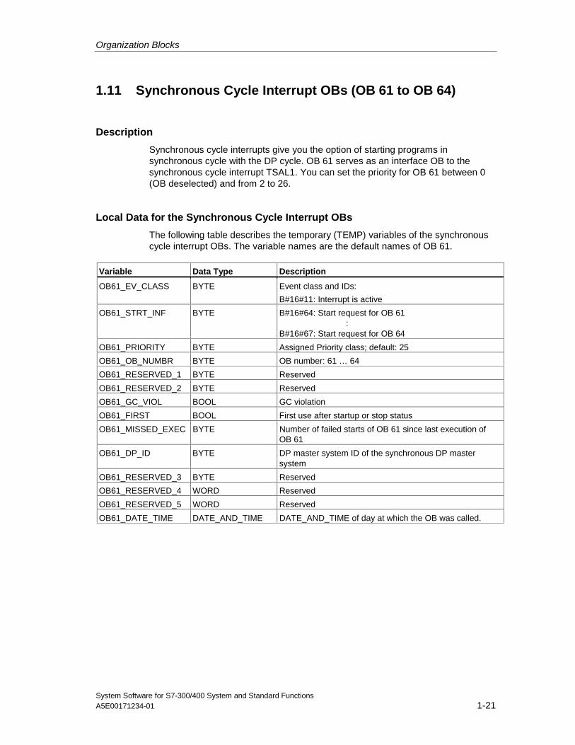
Synchronous cycle interrupts give you the option of starting programs insynchronous cycle with the DP cycle. OB 61 serves as an interface OB to thesynchronous cycle interrupt TSAL1. You can set the priority for OB 61 between 0(OB deselected) and from 2 to 26.
Local Data for the Synchronous Cycle Interrupt OBs
The following table describes the temporary (TEMP) variables of the synchronouscycle interrupt OBs. The variable names are the default names of OB 61.
Variable Data Type Description
OB61_EV_CLASS BYTE Event class and IDs:
B#16#11: Interrupt is active
OB61_STRT_INF BYTE B#16#64: Start request for OB 61:
B#16#67: Start request for OB 64
OB61_PRIORITY BYTE Assigned Priority class; default: 25
OB61_OB_NUMBR BYTE OB number: 61 … 64
OB61_RESERVED_1 BYTE Reserved
OB61_RESERVED_2 BYTE Reserved
OB61_GC_VIOL BOOL GC violation
OB61_FIRST BOOL First use after startup or stop status
OB61_MISSED_EXEC BYTE Number of failed starts of OB 61 since last execution ofOB 61
OB61_DP_ID BYTE DP master system ID of the synchronous DP mastersystem
OB61_RESERVED_3 BYTE Reserved
OB61_RESERVED_4 WORD Reserved
OB61_RESERVED_5 WORD Reserved
OB61_DATE_TIME DATE_AND_TIME DATE_AND_TIME of day at which the OB was called.
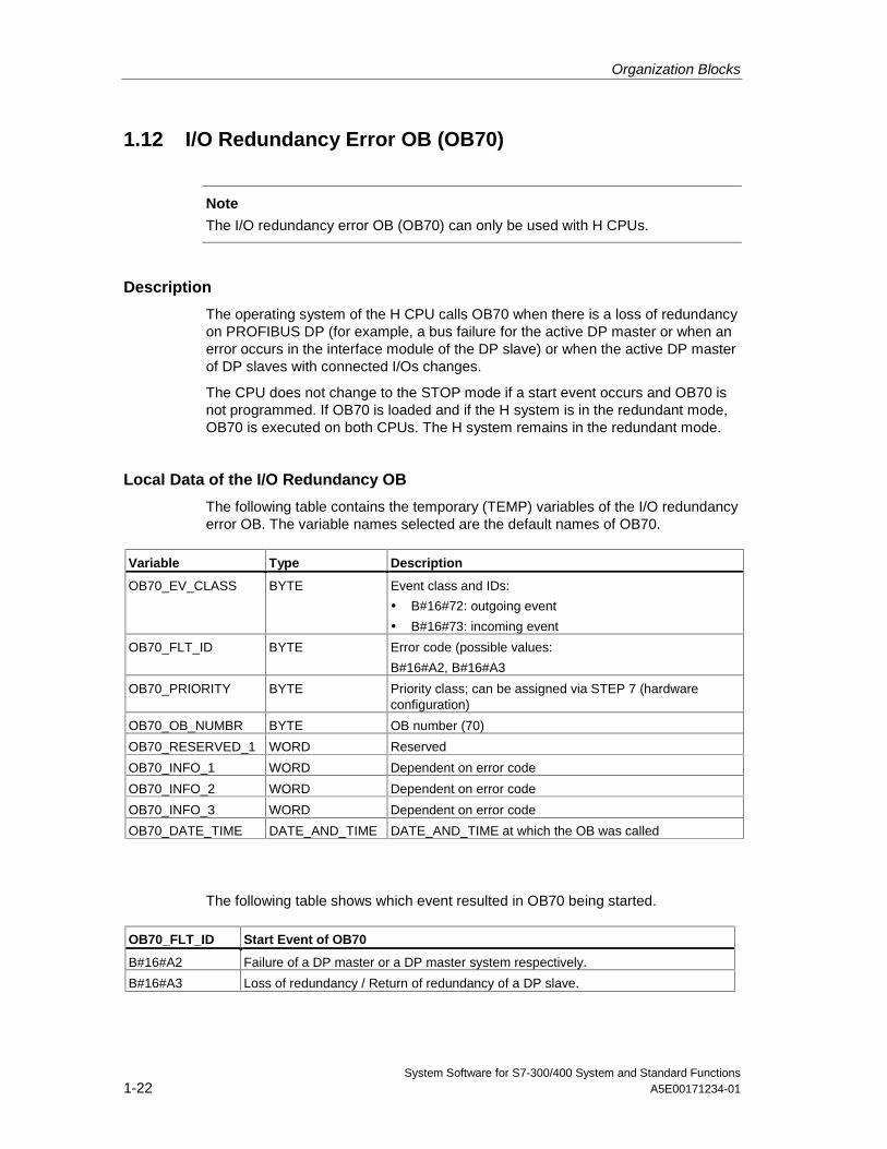
Organization Blocks
System Software for S7-300/400 System and Standard Functions1-22 A5E00171234-01
1.12 I/O Redundancy Error OB (OB70)
Note
The I/O redundancy error OB (OB70) can only be used with H CPUs.
Description
The operating system of the H CPU calls OB70 when there is a loss of redundancyon PROFIBUS DP (for example, a bus failure for the active DP master or when anerror occurs in the interface module of the DP slave) or when the active DP masterof DP slaves with connected I/Os changes.
The CPU does not change to the STOP mode if a start event occurs and OB70 isnot programmed. If OB70 is loaded and if the H system is in the redundant mode,OB70 is executed on both CPUs. The H system remains in the redundant mode.
Local Data of the I/O Redundancy OB
The following table contains the temporary (TEMP) variables of the I/O redundancyerror OB. The variable names selected are the default names of OB70.
Variable Type Description
OB70_EV_CLASS BYTE Event class and IDs:
• B#16#72: outgoing event
• B#16#73: incoming event
OB70_FLT_ID BYTE Error code (possible values:
B#16#A2, B#16#A3
OB70_PRIORITY BYTE Priority class; can be assigned via STEP 7 (hardwareconfiguration)
OB70_OB_NUMBR BYTE OB number (70)
OB70_RESERVED_1 WORD Reserved
OB70_INFO_1 WORD Dependent on error code
OB70_INFO_2 WORD Dependent on error code
OB70_INFO_3 WORD Dependent on error code
OB70_DATE_TIME DATE_AND_TIME DATE_AND_TIME at which the OB was called
The following table shows which event resulted in OB70 being started.
OB70_FLT_ID Start Event of OB70
B#16#A2 Failure of a DP master or a DP master system respectively.
B#16#A3 Loss of redundancy / Return of redundancy of a DP slave.
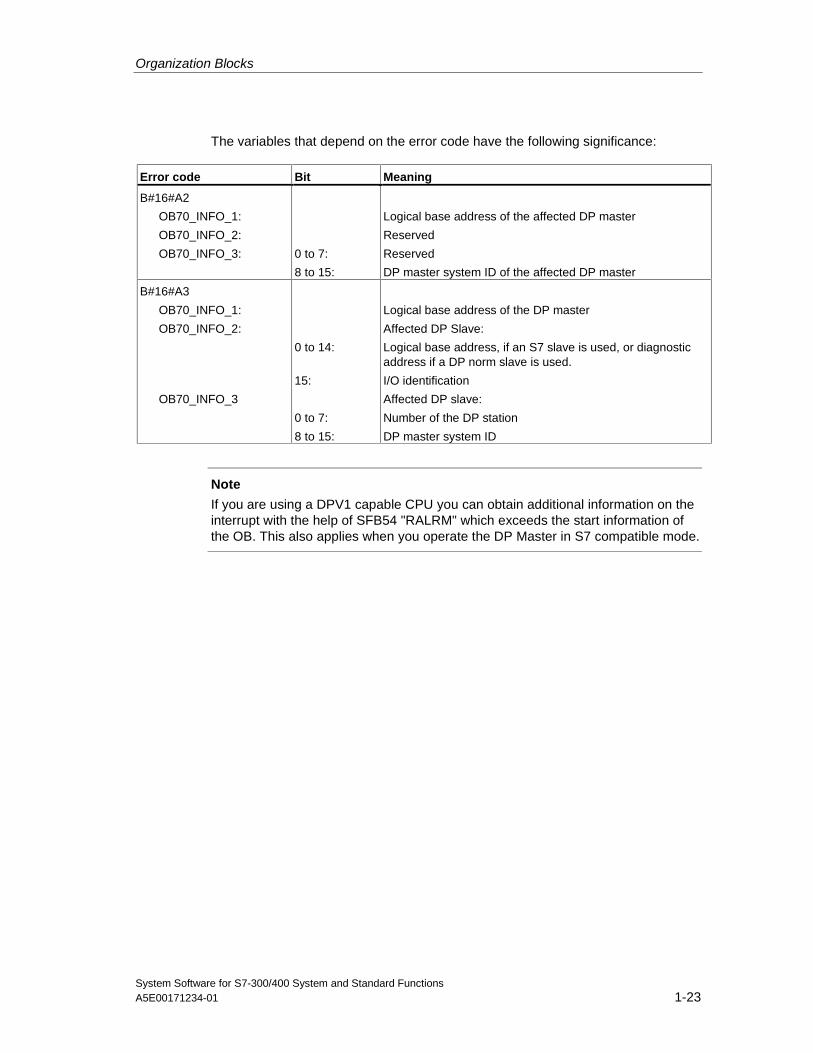
Organization Blocks
System Software for S7-300/400 System and Standard FunctionsA5E00171234-01 1-23
The variables that depend on the error code have the following significance:
Error code Bit Meaning
B#16#A2
OB70_INFO_1:
OB70_INFO_2:
OB70_INFO_3: 0 to 7:
8 to 15:
Logical base address of the affected DP master
Reserved
Reserved
DP master system ID of the affected DP master
B#16#A3
OB70_INFO_1:
OB70_INFO_2:
OB70_INFO_3
0 to 14:
15:
0 to 7:
8 to 15:
Logical base address of the DP master
Affected DP Slave:
Logical base address, if an S7 slave is used, or diagnosticaddress if a DP norm slave is used.
I/O identification
Affected DP slave:
Number of the DP station
DP master system ID
Note
If you are using a DPV1 capable CPU you can obtain additional information on theinterrupt with the help of SFB54 "RALRM" which exceeds the start information ofthe OB. This also applies when you operate the DP Master in S7 compatible mode.
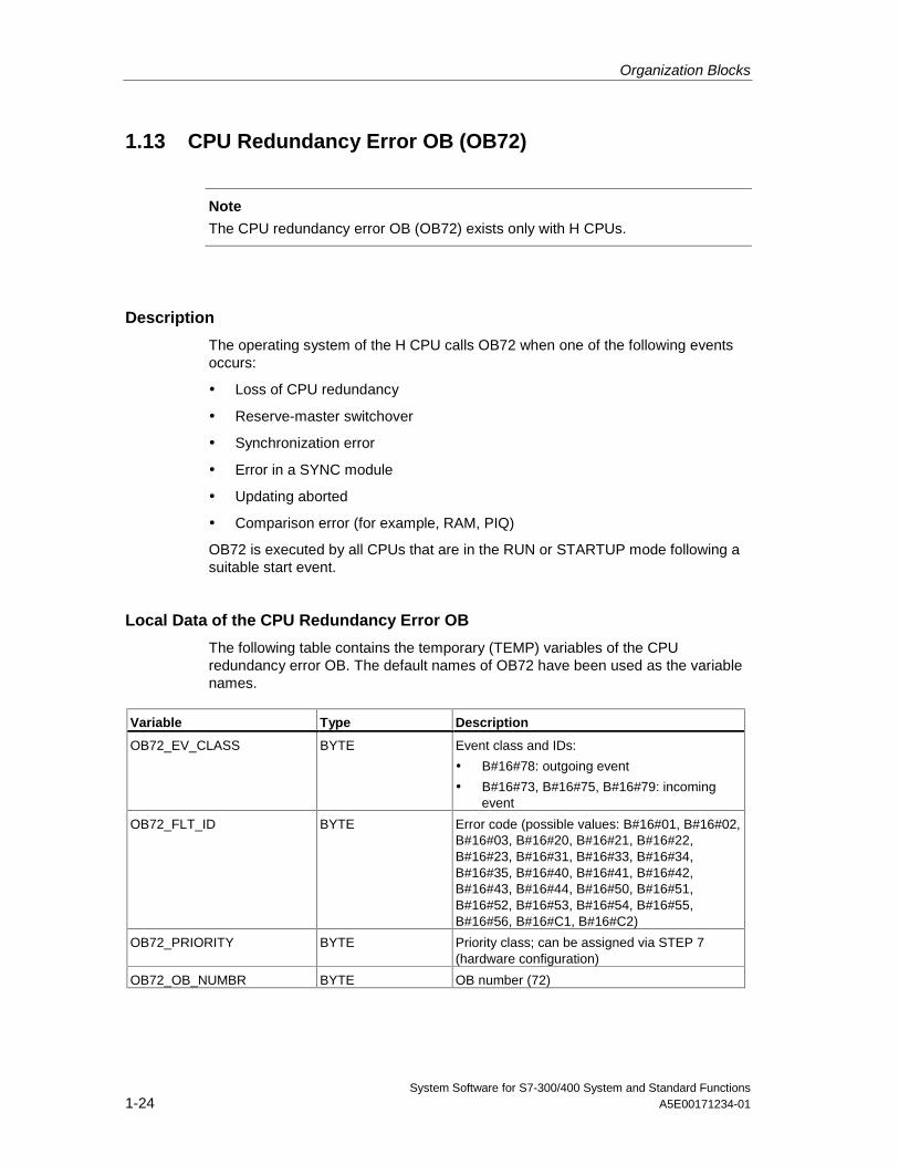
Organization Blocks
System Software for S7-300/400 System and Standard Functions1-24 A5E00171234-01
1.13 CPU Redundancy Error OB (OB72)
Note
The CPU redundancy error OB (OB72) exists only with H CPUs.
Description
The operating system of the H CPU calls OB72 when one of the following eventsoccurs:
• Loss of CPU redundancy
• Reserve-master switchover
• Synchronization error
• Error in a SYNC module
• Updating aborted
• Comparison error (for example, RAM, PIQ)
OB72 is executed by all CPUs that are in the RUN or STARTUP mode following asuitable start event.
Local Data of the CPU Redundancy Error OB
The following table contains the temporary (TEMP) variables of the CPUredundancy error OB. The default names of OB72 have been used as the variablenames.
Variable Type Description
OB72_EV_CLASS BYTE Event class and IDs:
• B#16#78: outgoing event
• B#16#73, B#16#75, B#16#79: incomingevent
OB72_FLT_ID BYTE Error code (possible values: B#16#01, B#16#02,B#16#03, B#16#20, B#16#21, B#16#22,B#16#23, B#16#31, B#16#33, B#16#34,B#16#35, B#16#40, B#16#41, B#16#42,B#16#43, B#16#44, B#16#50, B#16#51,B#16#52, B#16#53, B#16#54, B#16#55,B#16#56, B#16#C1, B#16#C2)
OB72_PRIORITY BYTE Priority class; can be assigned via STEP 7(hardware configuration)
OB72_OB_NUMBR BYTE OB number (72)
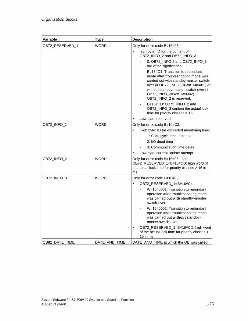
Organization Blocks
System Software for S7-300/400 System and Standard FunctionsA5E00171234-01 1-25
Variable Type Description
OB72_RESERVED_1 WORD Only for error code B#16#03:
• high byte: ID for the content ofOB72_INFO_2 and OB72_INFO_3
- 0: OB72_INFO-2 and OB72_INFO_3are of no significance
- B#16#C4: Transition to redundantmode after troubleshooting mode wascarried out with standby-master switch-over (if OB72_INFO_3=W#16#0001) orwithout standby-master switch-over (ifOB72_INFO_3=W#16#0002).OB72_INFO_2 is reserved.
- B#16#CD: OB72_INFO_2 andOB72_INFO_3 contain the actual locktime for priority classes > 15
• Low byte: reserved
OB72_INFO_1 WORD Only for error code B#16#C2:
• High byte: ID for exceeded monitoring time:
- 1: Scan cycle time increase
- 2: I/O dead time
- 3: Communication time delay
• Low byte: current update attempt
OB72_INFO_2 WORD Only for error code B#16#03 andOB72_RESERVED_1=B#16#CD: high word ofthe actual lock time for priority classes > 15 inms
OB72_INFO_3 WORD Only for error code B#16#03:
• OB72_RESERVED_1=B#16#C4:
- W#16#0001: Transition to redundantoperation after troubleshooting modewas carried out with standby-masterswitch-over
- W#16#0002: Transition to redundantoperation after troubleshooting modewas carried out without standby-master switch-over
• OB72_RESERVED_1=B#16#CD: high wordof the actual lock time for priority classes >15 in ms
OB82_DATE_TIME DATE_AND_TIME DATE_AND_TIME at which the OB was called
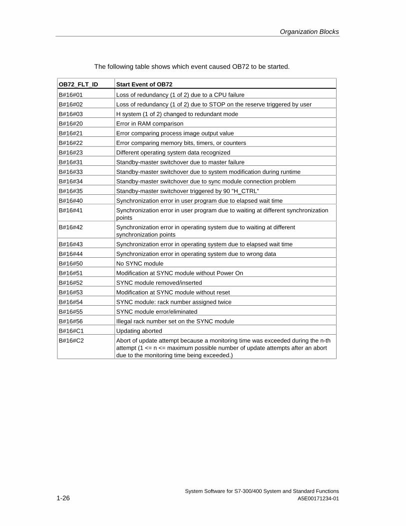
Organization Blocks
System Software for S7-300/400 System and Standard Functions1-26 A5E00171234-01
The following table shows which event caused OB72 to be started.
OB72_FLT_ID Start Event of OB72
B#16#01 Loss of redundancy (1 of 2) due to a CPU failure
B#16#02 Loss of redundancy (1 of 2) due to STOP on the reserve triggered by user
B#16#03 H system (1 of 2) changed to redundant mode
B#16#20 Error in RAM comparison
B#16#21 Error comparing process image output value
B#16#22 Error comparing memory bits, timers, or counters
B#16#23 Different operating system data recognized
B#16#31 Standby-master switchover due to master failure
B#16#33 Standby-master switchover due to system modification during runtime
B#16#34 Standby-master switchover due to sync module connection problem
B#16#35 Standby-master switchover triggered by 90 "H_CTRL"
B#16#40 Synchronization error in user program due to elapsed wait time
B#16#41 Synchronization error in user program due to waiting at different synchronizationpoints
B#16#42 Synchronization error in operating system due to waiting at differentsynchronization points
B#16#43 Synchronization error in operating system due to elapsed wait time
B#16#44 Synchronization error in operating system due to wrong data
B#16#50 No SYNC module
B#16#51 Modification at SYNC module without Power On
B#16#52 SYNC module removed/inserted
B#16#53 Modification at SYNC module without reset
B#16#54 SYNC module: rack number assigned twice
B#16#55 SYNC module error/eliminated
B#16#56 Illegal rack number set on the SYNC module
B#16#C1 Updating aborted
B#16#C2 Abort of update attempt because a monitoring time was exceeded during the n-thattempt (1 <= n <= maximum possible number of update attempts after an abortdue to the monitoring time being exceeded.)
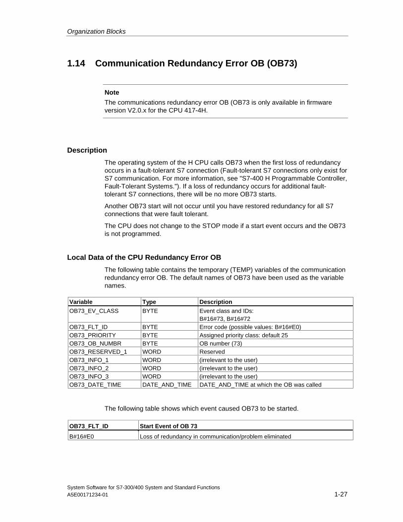
Organization Blocks
System Software for S7-300/400 System and Standard FunctionsA5E00171234-01 1-27
1.14 Communication Redundancy Error OB (OB73)
Note
The communications redundancy error OB (OB73 is only available in firmwareversion V2.0.x for the CPU 417-4H.
Description
The operating system of the H CPU calls OB73 when the first loss of redundancyoccurs in a fault-tolerant S7 connection (Fault-tolerant S7 connections only exist forS7 communication. For more information, see "S7-400 H Programmable Controller,Fault-Tolerant Systems."). If a loss of redundancy occurs for additional fault-tolerant S7 connections, there will be no more OB73 starts.
Another OB73 start will not occur until you have restored redundancy for all S7connections that were fault tolerant.
The CPU does not change to the STOP mode if a start event occurs and the OB73is not programmed.
Local Data of the CPU Redundancy Error OB
The following table contains the temporary (TEMP) variables of the communicationredundancy error OB. The default names of OB73 have been used as the variablenames.
Variable Type Description
OB73_EV_CLASS BYTE Event class and IDs:B#16#73, B#16#72
OB73_FLT_ID BYTE Error code (possible values: B#16#E0)OB73_PRIORITY BYTE Assigned priority class: default 25OB73_OB_NUMBR BYTE OB number (73)OB73_RESERVED_1 WORD ReservedOB73_INFO_1 WORD (irrelevant to the user)OB73_INFO_2 WORD (irrelevant to the user)OB73_INFO_3 WORD (irrelevant to the user)OB73_DATE_TIME DATE_AND_TIME DATE_AND_TIME at which the OB was called
The following table shows which event caused OB73 to be started.
OB73_FLT_ID Start Event of OB 73
B#16#E0 Loss of redundancy in communication/problem eliminated
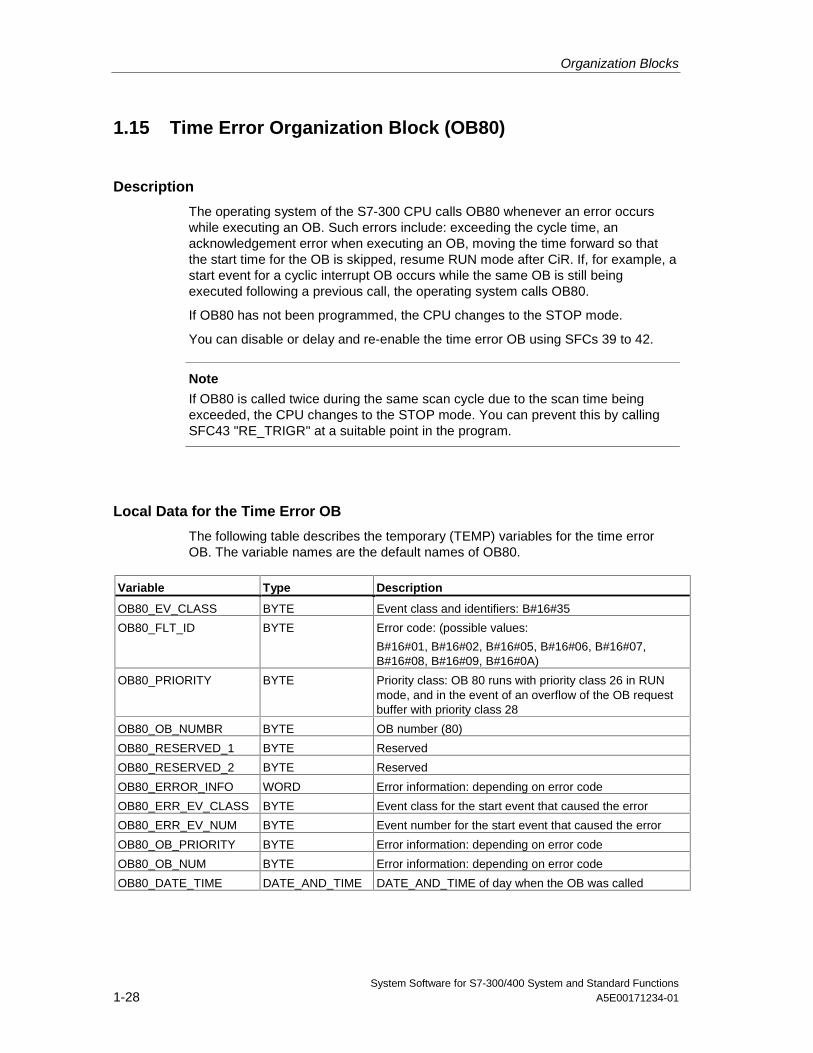
Organization Blocks
System Software for S7-300/400 System and Standard Functions1-28 A5E00171234-01
1.15 Time Error Organization Block (OB80)
Description
The operating system of the S7-300 CPU calls OB80 whenever an error occurswhile executing an OB. Such errors include: exceeding the cycle time, anacknowledgement error when executing an OB, moving the time forward so thatthe start time for the OB is skipped, resume RUN mode after CiR. If, for example, astart event for a cyclic interrupt OB occurs while the same OB is still beingexecuted following a previous call, the operating system calls OB80.
If OB80 has not been programmed, the CPU changes to the STOP mode.
You can disable or delay and re-enable the time error OB using SFCs 39 to 42.
Note
If OB80 is called twice during the same scan cycle due to the scan time beingexceeded, the CPU changes to the STOP mode. You can prevent this by callingSFC43 "RE_TRIGR" at a suitable point in the program.
Local Data for the Time Error OB
The following table describes the temporary (TEMP) variables for the time errorOB. The variable names are the default names of OB80.
Variable Type Description
OB80_EV_CLASS BYTE Event class and identifiers: B#16#35
OB80_FLT_ID BYTE Error code: (possible values:
B#16#01, B#16#02, B#16#05, B#16#06, B#16#07,B#16#08, B#16#09, B#16#0A)
OB80_PRIORITY BYTE Priority class: OB 80 runs with priority class 26 in RUNmode, and in the event of an overflow of the OB requestbuffer with priority class 28
OB80_OB_NUMBR BYTE OB number (80)
OB80_RESERVED_1 BYTE Reserved
OB80_RESERVED_2 BYTE Reserved
OB80_ERROR_INFO WORD Error information: depending on error code
OB80_ERR_EV_CLASS BYTE Event class for the start event that caused the error
OB80_ERR_EV_NUM BYTE Event number for the start event that caused the error
OB80_OB_PRIORITY BYTE Error information: depending on error code
OB80_OB_NUM BYTE Error information: depending on error code
OB80_DATE_TIME DATE_AND_TIME DATE_AND_TIME of day when the OB was called
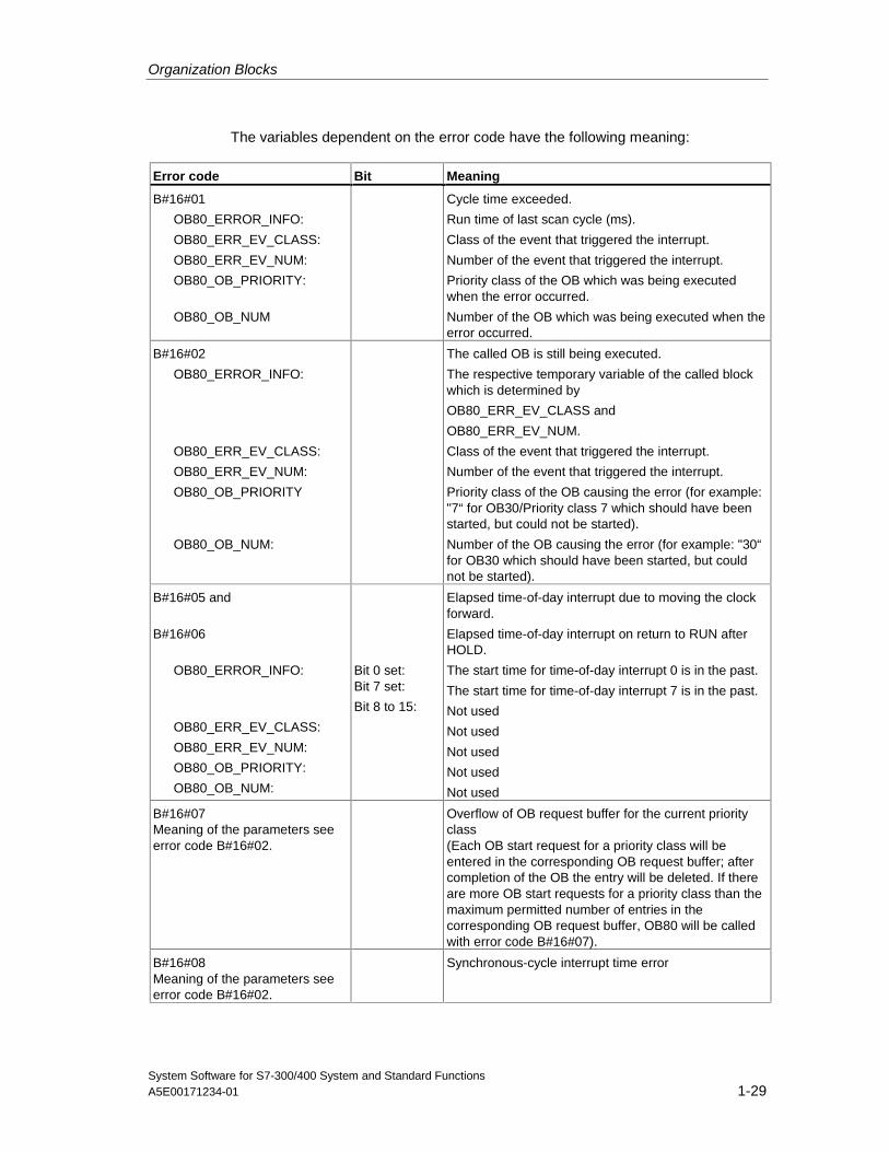
Organization Blocks
System Software for S7-300/400 System and Standard FunctionsA5E00171234-01 1-29
The variables dependent on the error code have the following meaning:
Error code Bit Meaning
B#16#01
OB80_ERROR_INFO:
OB80_ERR_EV_CLASS:
OB80_ERR_EV_NUM:
OB80_OB_PRIORITY:
OB80_OB_NUM
Cycle time exceeded.
Run time of last scan cycle (ms).
Class of the event that triggered the interrupt.
Number of the event that triggered the interrupt.
Priority class of the OB which was being executedwhen the error occurred.
Number of the OB which was being executed when theerror occurred.
B#16#02
OB80_ERROR_INFO:
OB80_ERR_EV_CLASS:
OB80_ERR_EV_NUM:
OB80_OB_PRIORITY
OB80_OB_NUM:
The called OB is still being executed.
The respective temporary variable of the called blockwhich is determined by
OB80_ERR_EV_CLASS and
OB80_ERR_EV_NUM.
Class of the event that triggered the interrupt.
Number of the event that triggered the interrupt.
Priority class of the OB causing the error (for example:"7“ for OB30/Priority class 7 which should have beenstarted, but could not be started).
Number of the OB causing the error (for example: "30“for OB30 which should have been started, but couldnot be started).
B#16#05 and
B#16#06
OB80_ERROR_INFO:
OB80_ERR_EV_CLASS:
OB80_ERR_EV_NUM:
OB80_OB_PRIORITY:
OB80_OB_NUM:
Bit 0 set:Bit 7 set:
Bit 8 to 15:
Elapsed time-of-day interrupt due to moving the clockforward.
Elapsed time-of-day interrupt on return to RUN afterHOLD.
The start time for time-of-day interrupt 0 is in the past.
The start time for time-of-day interrupt 7 is in the past.
Not used
Not used
Not used
Not used
Not used
B#16#07Meaning of the parameters seeerror code B#16#02.
Overflow of OB request buffer for the current priorityclass(Each OB start request for a priority class will beentered in the corresponding OB request buffer; aftercompletion of the OB the entry will be deleted. If thereare more OB start requests for a priority class than themaximum permitted number of entries in thecorresponding OB request buffer, OB80 will be calledwith error code B#16#07).
B#16#08Meaning of the parameters seeerror code B#16#02.
Synchronous-cycle interrupt time error
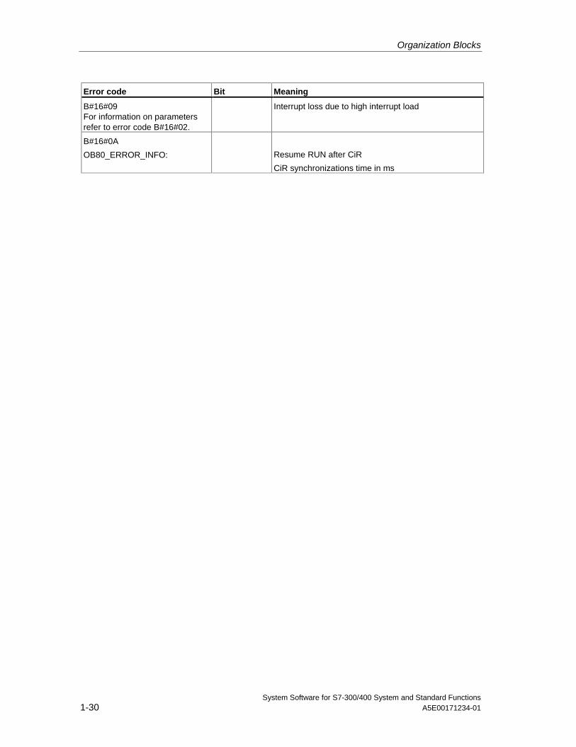
Organization Blocks
System Software for S7-300/400 System and Standard Functions1-30 A5E00171234-01
Error code Bit Meaning
B#16#09For information on parametersrefer to error code B#16#02.
Interrupt loss due to high interrupt load
B#16#0A
OB80_ERROR_INFO: Resume RUN after CiR
CiR synchronizations time in ms
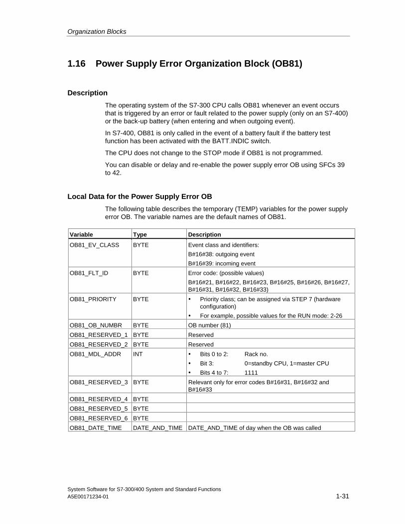
Organization Blocks
System Software for S7-300/400 System and Standard FunctionsA5E00171234-01 1-31
1.16 Power Supply Error Organization Block (OB81)
Description
The operating system of the S7-300 CPU calls OB81 whenever an event occursthat is triggered by an error or fault related to the power supply (only on an S7-400)or the back-up battery (when entering and when outgoing event).
In S7-400, OB81 is only called in the event of a battery fault if the battery testfunction has been activated with the BATT.INDIC switch.
The CPU does not change to the STOP mode if OB81 is not programmed.
You can disable or delay and re-enable the power supply error OB using SFCs 39to 42.
Local Data for the Power Supply Error OB
The following table describes the temporary (TEMP) variables for the power supplyerror OB. The variable names are the default names of OB81.
Variable Type Description
OB81_EV_CLASS BYTE Event class and identifiers:
B#16#38: outgoing event
B#16#39: incoming event
OB81_FLT_ID BYTE Error code: (possible values)
B#16#21, B#16#22, B#16#23, B#16#25, B#16#26, B#16#27,B#16#31, B#16#32, B#16#33)
OB81_PRIORITY BYTE • Priority class; can be assigned via STEP 7 (hardwareconfiguration)
• For example, possible values for the RUN mode: 2-26
OB81_OB_NUMBR BYTE OB number (81)
OB81_RESERVED_1 BYTE Reserved
OB81_RESERVED_2 BYTE Reserved
OB81_MDL_ADDR INT • Bits 0 to 2: Rack no.
• Bit 3: 0=standby CPU, 1=master CPU
• Bits 4 to 7: 1111
OB81_RESERVED_3 BYTE Relevant only for error codes B#16#31, B#16#32 andB#16#33
OB81_RESERVED_4 BYTE
OB81_RESERVED_5 BYTE
OB81_RESERVED_6 BYTE
OB81_DATE_TIME DATE_AND_TIME DATE_AND_TIME of day when the OB was called
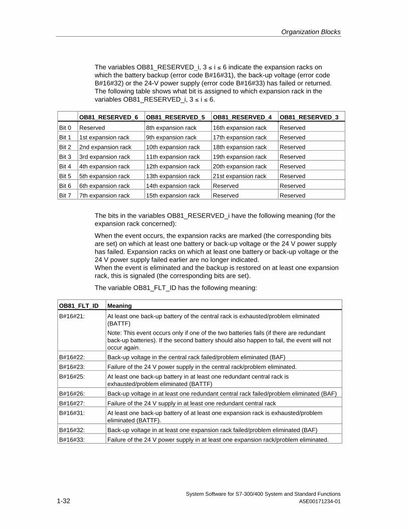
Organization Blocks
System Software for S7-300/400 System and Standard Functions1-32 A5E00171234-01
The variables OB81_RESERVED_i, 3 ≤ i ≤ 6 indicate the expansion racks onwhich the battery backup (error code B#16#31), the back-up voltage (error codeB#16#32) or the 24-V power supply (error code B#16#33) has failed or returned.The following table shows what bit is assigned to which expansion rack in thevariables OB81_RESERVED_i, 3 ≤ i ≤ 6.
OB81_RESERVED_6 OB81_RESERVED_5 OB81_RESERVED_4 OB81_RESERVED_3
Bit 0 Reserved 8th expansion rack 16th expansion rack Reserved
Bit 1 1st expansion rack 9th expansion rack 17th expansion rack Reserved
Bit 2 2nd expansion rack 10th expansion rack 18th expansion rack Reserved
Bit 3 3rd expansion rack 11th expansion rack 19th expansion rack Reserved
Bit 4 4th expansion rack 12th expansion rack 20th expansion rack Reserved
Bit 5 5th expansion rack 13th expansion rack 21st expansion rack Reserved
Bit 6 6th expansion rack 14th expansion rack Reserved Reserved
Bit 7 7th expansion rack 15th expansion rack Reserved Reserved
The bits in the variables OB81_RESERVED_i have the following meaning (for theexpansion rack concerned):
When the event occurs, the expansion racks are marked (the corresponding bitsare set) on which at least one battery or back-up voltage or the 24 V power supplyhas failed. Expansion racks on which at least one battery or back-up voltage or the24 V power supply failed earlier are no longer indicated.When the event is eliminated and the backup is restored on at least one expansionrack, this is signaled (the corresponding bits are set).
The variable OB81_FLT_ID has the following meaning:
OB81_FLT_ID Meaning
B#16#21: At least one back-up battery of the central rack is exhausted/problem eliminated(BATTF)
Note: This event occurs only if one of the two batteries fails (if there are redundantback-up batteries). If the second battery should also happen to fail, the event will notoccur again.
B#16#22: Back-up voltage in the central rack failed/problem eliminated (BAF)
B#16#23: Failure of the 24 V power supply in the central rack/problem eliminated.
B#16#25: At least one back-up battery in at least one redundant central rack isexhausted/problem eliminated (BATTF)
B#16#26: Back-up voltage in at least one redundant central rack failed/problem eliminated (BAF)
B#16#27: Failure of the 24 V supply in at least one redundant central rack
B#16#31: At least one back-up battery of at least one expansion rack is exhausted/problemeliminated (BATTF).
B#16#32: Back-up voltage in at least one expansion rack failed/problem eliminated (BAF)
B#16#33: Failure of the 24 V power supply in at least one expansion rack/problem eliminated.
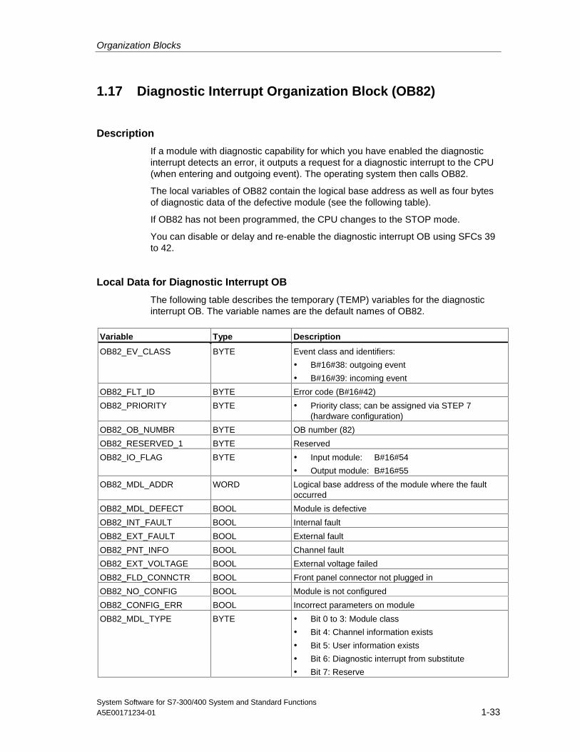
Organization Blocks
System Software for S7-300/400 System and Standard FunctionsA5E00171234-01 1-33
1.17 Diagnostic Interrupt Organization Block (OB82)
Description
If a module with diagnostic capability for which you have enabled the diagnosticinterrupt detects an error, it outputs a request for a diagnostic interrupt to the CPU(when entering and outgoing event). The operating system then calls OB82.
The local variables of OB82 contain the logical base address as well as four bytesof diagnostic data of the defective module (see the following table).
If OB82 has not been programmed, the CPU changes to the STOP mode.
You can disable or delay and re-enable the diagnostic interrupt OB using SFCs 39to 42.
Local Data for Diagnostic Interrupt OB
The following table describes the temporary (TEMP) variables for the diagnosticinterrupt OB. The variable names are the default names of OB82.
Variable Type Description
OB82_EV_CLASS BYTE Event class and identifiers:
• B#16#38: outgoing event
• B#16#39: incoming event
OB82_FLT_ID BYTE Error code (B#16#42)
OB82_PRIORITY BYTE • Priority class; can be assigned via STEP 7(hardware configuration)
OB82_OB_NUMBR BYTE OB number (82)
OB82_RESERVED_1 BYTE Reserved
OB82_IO_FLAG BYTE • Input module: B#16#54
• Output module: B#16#55
OB82_MDL_ADDR WORD Logical base address of the module where the faultoccurred
OB82_MDL_DEFECT BOOL Module is defective
OB82_INT_FAULT BOOL Internal fault
OB82_EXT_FAULT BOOL External fault
OB82_PNT_INFO BOOL Channel fault
OB82_EXT_VOLTAGE BOOL External voltage failed
OB82_FLD_CONNCTR BOOL Front panel connector not plugged in
OB82_NO_CONFIG BOOL Module is not configured
OB82_CONFIG_ERR BOOL Incorrect parameters on module
OB82_MDL_TYPE BYTE • Bit 0 to 3: Module class
• Bit 4: Channel information exists
• Bit 5: User information exists
• Bit 6: Diagnostic interrupt from substitute
• Bit 7: Reserve
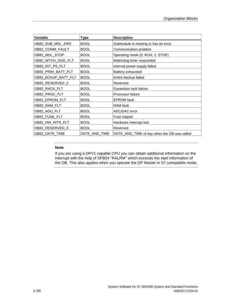
Organization Blocks
System Software for S7-300/400 System and Standard Functions1-34 A5E00171234-01
Variable Type Description
OB82_SUB_MDL_ERR BOOL Submodule is missing or has an error
OB82_COMM_FAULT BOOL Communication problem
OB82_MDL_STOP BOOL Operating mode (0: RUN, 1: STOP)
OB82_WTCH_DOG_FLT BOOL Watchdog timer responded
OB82_INT_PS_FLT BOOL Internal power supply failed
OB82_PRIM_BATT_FLT BOOL Battery exhausted
OB82_BCKUP_BATT_FLT BOOL Entire backup failed
OB82_RESERVED_2 BOOL Reserved
OB82_RACK_FLT BOOL Expansion rack failure
OB82_PROC_FLT BOOL Processor failure
OB82_EPROM_FLT BOOL EPROM fault
OB82_RAM_FLT BOOL RAM fault
OB82_ADU_FLT BOOL ADC/DAC error
OB82_FUSE_FLT BOOL Fuse tripped
OB82_HW_INTR_FLT BOOL Hardware interrupt lost
OB82_RESERVED_3 BOOL Reserved
OB82_DATE_TIME DATE_AND_TIME DATE_AND_TIME of day when the OB was called
Note
If you are using a DPV1 capable CPU you can obtain additional information on theinterrupt with the help of SFB54 "RALRM" which exceeds the start information ofthe OB. This also applies when you operate the DP Master in S7 compatible mode.
Organization Blocks
System Software for S7-300/400 System and Standard FunctionsA5E00171234-01 1-35
1.18 Insert / Remove Module Interrupt Organization Block(OB83)
Description
The CPU operating system calls OB 83 in following situations:
• after insertion / removal of a configured module
• after modifications of module parameters under STEP 7 and download ofchanges to the CPU during RUN
You can disable/delay/enable the insert/remove interrupt OB with the help of SFCs39 to 42.
Module insertion and removal
Each time a configured module is removed or inserted during the RUN, STOP, andSTARTUP modes, an insert/remove interrupt is generated (power supply modules,CPUs, adapter modules and IMs must not be removed in these modes). Thisinterrupt causes an entry in the diagnostic buffer and in the system status list forthe CPU involved. The insert/remove OB is also started if the CPU is in the RUNmode. If this OB has not been programmed, the CPU changes to the STOP mode.
Then system polls S7-400 modules in seconds intervals to detect insertion orremoval. To enable the CPU to detect the removal and insertion of an S7-400module, a minimum time interval of two seconds must expire between removal andinsertion. This minimum time is slightly higher for other modules.
If you remove a configured module in the RUN mode, OB83 is started. Since theexistence of modules is only monitored at intervals of one second, an access errormay be detected first if the module is accessed directly or when the process imageis updated.
If you insert a module in a configured slot in the RUN mode, the operating systemchecks whether the type of the module inserted corresponds to the recordedconfiguration. OB83 is then started and parameters are assigned if the moduletypes match.
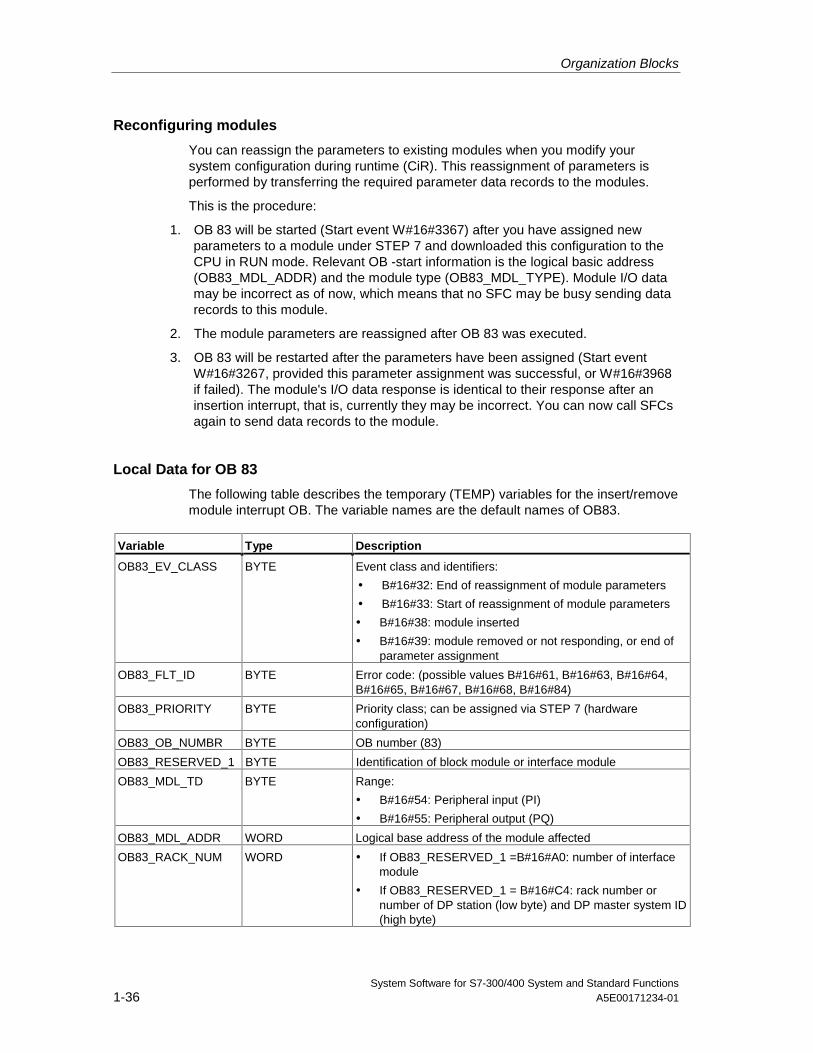
Organization Blocks
System Software for S7-300/400 System and Standard Functions1-36 A5E00171234-01
Reconfiguring modules
You can reassign the parameters to existing modules when you modify yoursystem configuration during runtime (CiR). This reassignment of parameters isperformed by transferring the required parameter data records to the modules.
This is the procedure:
1. OB 83 will be started (Start event W#16#3367) after you have assigned newparameters to a module under STEP 7 and downloaded this configuration to theCPU in RUN mode. Relevant OB -start information is the logical basic address(OB83_MDL_ADDR) and the module type (OB83_MDL_TYPE). Module I/O datamay be incorrect as of now, which means that no SFC may be busy sending datarecords to this module.
2. The module parameters are reassigned after OB 83 was executed.
3. OB 83 will be restarted after the parameters have been assigned (Start eventW#16#3267, provided this parameter assignment was successful, or W#16#3968if failed). The module's I/O data response is identical to their response after aninsertion interrupt, that is, currently they may be incorrect. You can now call SFCsagain to send data records to the module.
Local Data for OB 83
The following table describes the temporary (TEMP) variables for the insert/removemodule interrupt OB. The variable names are the default names of OB83.
Variable Type Description
OB83_EV_CLASS BYTE Event class and identifiers:
• B#16#32: End of reassignment of module parameters
• B#16#33: Start of reassignment of module parameters
• B#16#38: module inserted
• B#16#39: module removed or not responding, or end ofparameter assignment
OB83_FLT_ID BYTE Error code: (possible values B#16#61, B#16#63, B#16#64,B#16#65, B#16#67, B#16#68, B#16#84)
OB83_PRIORITY BYTE Priority class; can be assigned via STEP 7 (hardwareconfiguration)
OB83_OB_NUMBR BYTE OB number (83)
OB83_RESERVED_1 BYTE Identification of block module or interface module
OB83_MDL_TD BYTE Range:
• B#16#54: Peripheral input (PI)
• B#16#55: Peripheral output (PQ)
OB83_MDL_ADDR WORD Logical base address of the module affected
OB83_RACK_NUM WORD • If OB83_RESERVED_1 =B#16#A0: number of interfacemodule
• If OB83_RESERVED_1 = B#16#C4: rack number ornumber of DP station (low byte) and DP master system ID(high byte)
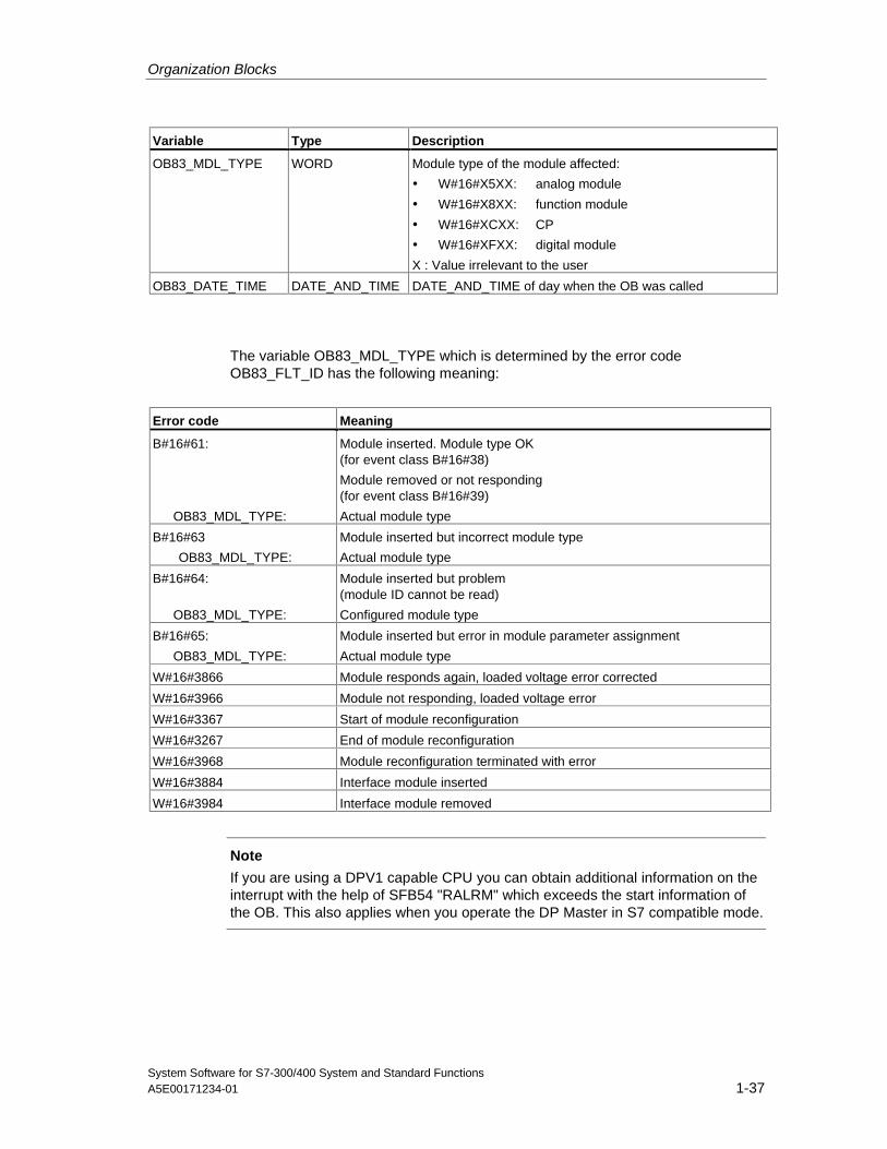
Organization Blocks
System Software for S7-300/400 System and Standard FunctionsA5E00171234-01 1-37
Variable Type Description
OB83_MDL_TYPE WORD Module type of the module affected:
• W#16#X5XX: analog module
• W#16#X8XX: function module
• W#16#XCXX: CP
• W#16#XFXX: digital module
X : Value irrelevant to the user
OB83_DATE_TIME DATE_AND_TIME DATE_AND_TIME of day when the OB was called
The variable OB83_MDL_TYPE which is determined by the error codeOB83_FLT_ID has the following meaning:
Error code Meaning
B#16#61:
OB83_MDL_TYPE:
Module inserted. Module type OK(for event class B#16#38)
Module removed or not responding(for event class B#16#39)
Actual module type
B#16#63
OB83_MDL_TYPE:
Module inserted but incorrect module type
Actual module type
B#16#64:
OB83_MDL_TYPE:
Module inserted but problem(module ID cannot be read)
Configured module type
B#16#65:
OB83_MDL_TYPE:
Module inserted but error in module parameter assignment
Actual module type
W#16#3866 Module responds again, loaded voltage error corrected
W#16#3966 Module not responding, loaded voltage error
W#16#3367 Start of module reconfiguration
W#16#3267 End of module reconfiguration
W#16#3968 Module reconfiguration terminated with error
W#16#3884 Interface module inserted
W#16#3984 Interface module removed
Note
If you are using a DPV1 capable CPU you can obtain additional information on theinterrupt with the help of SFB54 "RALRM" which exceeds the start information ofthe OB. This also applies when you operate the DP Master in S7 compatible mode.
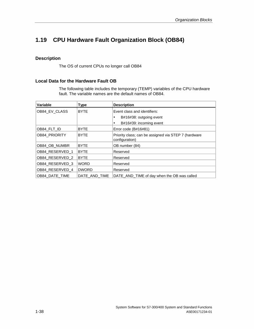
Organization Blocks
System Software for S7-300/400 System and Standard Functions1-38 A5E00171234-01
1.19 CPU Hardware Fault Organization Block (OB84)
Description
The OS of current CPUs no longer call OB84
Local Data for the Hardware Fault OB
The following table includes the temporary (TEMP) variables of the CPU hardwarefault. The variable names are the default names of OB84.
Variable Type Description
OB84_EV_CLASS BYTE Event class and identifiers:
• B#16#38: outgoing event
• B#16#39: incoming event
OB84_FLT_ID BYTE Error code (B#16#81)
OB84_PRIORITY BYTE Priority class; can be assigned via STEP 7 (hardwareconfiguration)
OB84_OB_NUMBR BYTE OB number (84)
OB84_RESERVED_1 BYTE Reserved
OB84_RESERVED_2 BYTE Reserved
OB84_RESERVED_3 WORD Reserved
OB84_RESERVED_4 DWORD Reserved
OB84_DATE_TIME DATE_AND_TIME DATE_AND_TIME of day when the OB was called
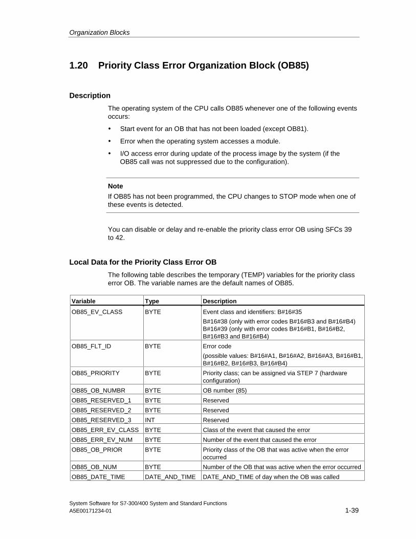
Organization Blocks
System Software for S7-300/400 System and Standard FunctionsA5E00171234-01 1-39
1.20 Priority Class Error Organization Block (OB85)
Description
The operating system of the CPU calls OB85 whenever one of the following eventsoccurs:
• Start event for an OB that has not been loaded (except OB81).
• Error when the operating system accesses a module.
• I/O access error during update of the process image by the system (if theOB85 call was not suppressed due to the configuration).
Note
If OB85 has not been programmed, the CPU changes to STOP mode when one ofthese events is detected.
You can disable or delay and re-enable the priority class error OB using SFCs 39to 42.
Local Data for the Priority Class Error OB
The following table describes the temporary (TEMP) variables for the priority classerror OB. The variable names are the default names of OB85.
Variable Type Description
OB85_EV_CLASS BYTE Event class and identifiers: B#16#35
B#16#38 (only with error codes B#16#B3 and B#16#B4)B#16#39 (only with error codes B#16#B1, B#16#B2,B#16#B3 and B#16#B4)
OB85_FLT_ID BYTE Error code
(possible values: B#16#A1, B#16#A2, B#16#A3, B#16#B1,B#16#B2, B#16#B3, B#16#B4)
OB85_PRIORITY BYTE Priority class; can be assigned via STEP 7 (hardwareconfiguration)
OB85_OB_NUMBR BYTE OB number (85)
OB85_RESERVED_1 BYTE Reserved
OB85_RESERVED_2 BYTE Reserved
OB85_RESERVED_3 INT Reserved
OB85_ERR_EV_CLASS BYTE Class of the event that caused the error
OB85_ERR_EV_NUM BYTE Number of the event that caused the error
OB85_OB_PRIOR BYTE Priority class of the OB that was active when the erroroccurred
OB85_OB_NUM BYTE Number of the OB that was active when the error occurred
OB85_DATE_TIME DATE_AND_TIME DATE_AND_TIME of day when the OB was called
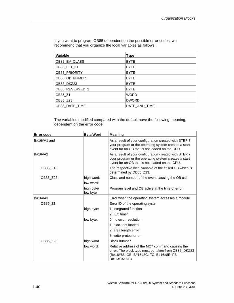
Organization Blocks
System Software for S7-300/400 System and Standard Functions1-40 A5E00171234-01
If you want to program OB85 dependent on the possible error codes, werecommend that you organize the local variables as follows:
Variable Type
OB85_EV_CLASS BYTE
OB85_FLT_ID BYTE
OB85_PRIORITY BYTE
OB85_OB_NUMBR BYTE
OB85_DKZ23 BYTE
OB85_RESERVED_2 BYTE
OB85_Z1 WORD
OB85_Z23 DWORD
OB85_DATE_TIME DATE_AND_TIME
The variables modified compared with the default have the following meaning,dependent on the error code:
Error code Byte/Word Meaning
B#16#A1 and
B#16#A2
OB85_Z1:
OB85_Z23: high word:
low word:
high byte/low byte
As a result of your configuration created with STEP 7,your program or the operating system creates a startevent for an OB that is not loaded on the CPU.
As a result of your configuration created with STEP 7,your program or the operating system creates a startevent for an OB that is not loaded on the CPU.
The respective local variable of the called OB which isdetermined by OB85_Z23.
Class and number of the event causing the OB call
Program level and OB active at the time of error
B#16#A3
OB85_Z1:
OB85_Z23
high byte:
low byte:
high word
low word:
Error when the operating system accesses a module
Error ID of the operating system
1: integrated function
2: IEC timer
0: no error resolution
1: block not loaded
2: area length error
3: write-protect error
Block number
Relative address of the MC7 command causing theerror. The block type must be taken from OB85_DKZ23(B#16#88: OB, B#16#8C: FC, B#16#8E: FB,B#16#8A: DB).
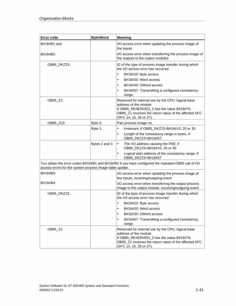
Organization Blocks
System Software for S7-300/400 System and Standard FunctionsA5E00171234-01 1-41
Error code Byte/Word Meaning
B#16#B1 and
B#16#B2:
I/O access error when updating the process image ofthe inputs
I/O access error when transferring the process image ofthe outputs to the output modules
OB85_DKZ23: ID of the type of process image transfer during whichthe I/O access error has occurred
• B#16#10: Byte access
• B#16#20: Word access
• B#16#30: DWord access
• B#16#57: Transmitting a configured consistencyrange
OB85_Z1: Reserved for internal use by the CPU: logical baseaddress of the moduleIf OB85_RESERVED_2 has the value B#16#76,OB85_Z1 receives the return value of the affected SFC(SFC 14, 15, 26 or 27).
OB85_Z23: Byte 0: Part process image no.
Byte 1: • Irrelevant, if OB85_DKZ23=B#16#10, 20 or 30
• Length of the consistency range in bytes, ifOB85_DKZ23=B#16#57
Bytes 2 and 3 • The I/O address causing the PAE, ifOB85_DKZ23=B#16#10, 20 or 30
• Logical start address of the consistency range, ifOB85_DKZ23=B#16#57
You obtain the error codes B#16#B1 and B#16#B2 if you have configured the repeated OB85 call of I/Oaccess errors for the system process image table update.
B#16#B3:
B#16#B4:
I/O access error when updating the process image ofthe inputs, incoming/outgoing event
I/O access error when transferring the output processimage to the output module, incoming/outgoing event
OB85_DKZ23: ID of the type of process image transfer during whichthe I/O access error has occurred
• B#16#10: Byte access
• B#16#20: Word access
• B#16#30: DWord access
• B#16#57: Transmitting a configured consistencyrange
OB85_Z1: Reserved for internal use by the CPU: logical baseaddress of the moduleIf OB85_RESERVED_2 has the value B#16#76,OB85_Z1 receives the return value of the affected SFC(SFC 14, 15, 26 or 27).
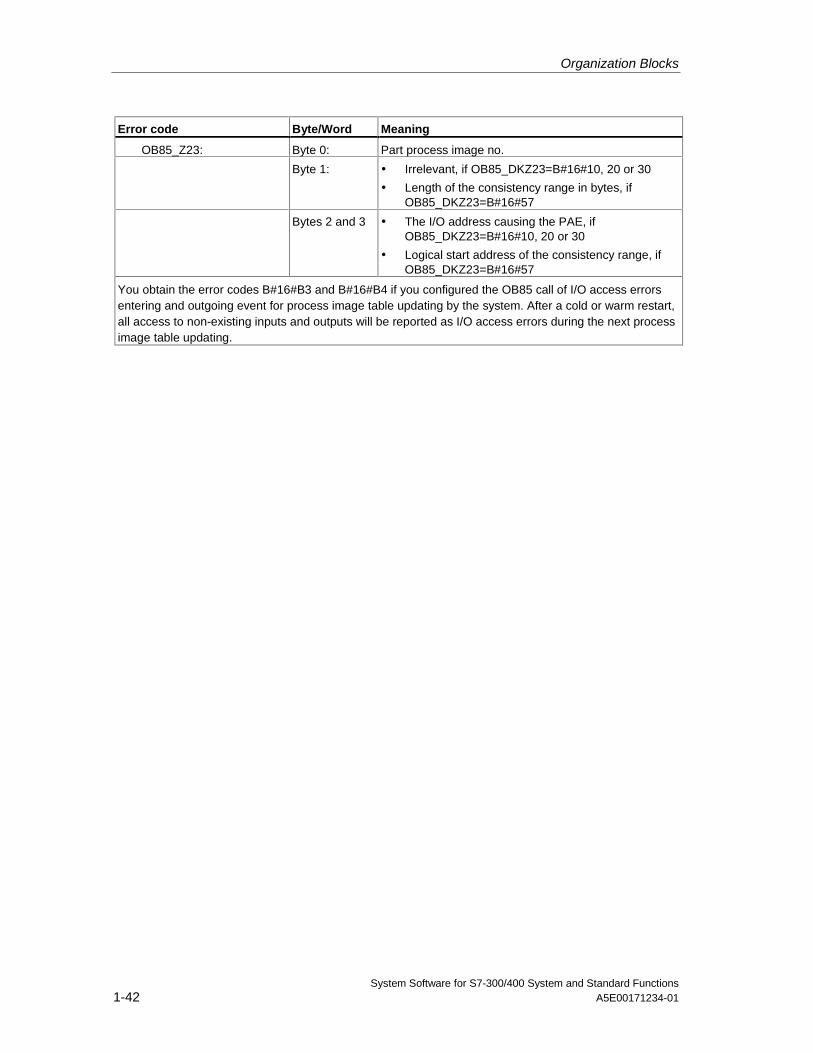
Organization Blocks
System Software for S7-300/400 System and Standard Functions1-42 A5E00171234-01
Error code Byte/Word Meaning
OB85_Z23: Byte 0: Part process image no.
Byte 1: • Irrelevant, if OB85_DKZ23=B#16#10, 20 or 30
• Length of the consistency range in bytes, ifOB85_DKZ23=B#16#57
Bytes 2 and 3 • The I/O address causing the PAE, ifOB85_DKZ23=B#16#10, 20 or 30
• Logical start address of the consistency range, ifOB85_DKZ23=B#16#57
You obtain the error codes B#16#B3 and B#16#B4 if you configured the OB85 call of I/O access errorsentering and outgoing event for process image table updating by the system. After a cold or warm restart,all access to non-existing inputs and outputs will be reported as I/O access errors during the next processimage table updating.
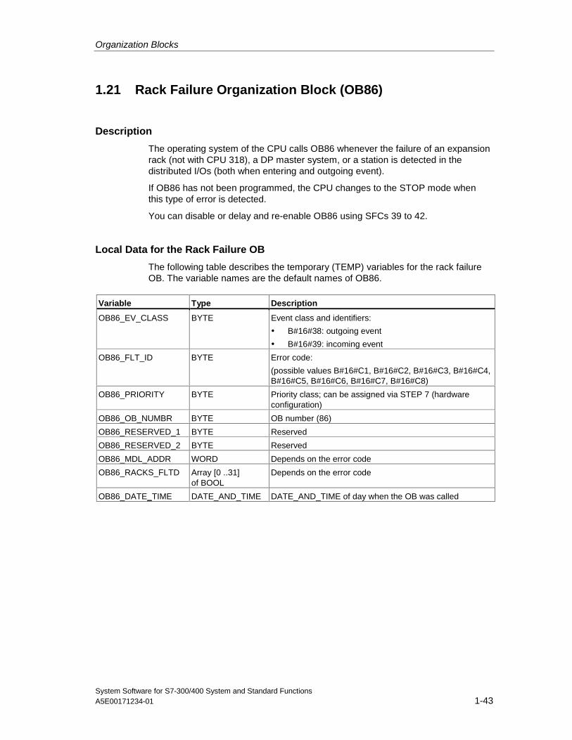
Organization Blocks
System Software for S7-300/400 System and Standard FunctionsA5E00171234-01 1-43
1.21 Rack Failure Organization Block (OB86)
Description
The operating system of the CPU calls OB86 whenever the failure of an expansionrack (not with CPU 318), a DP master system, or a station is detected in thedistributed I/Os (both when entering and outgoing event).
If OB86 has not been programmed, the CPU changes to the STOP mode whenthis type of error is detected.
You can disable or delay and re-enable OB86 using SFCs 39 to 42.
Local Data for the Rack Failure OB
The following table describes the temporary (TEMP) variables for the rack failureOB. The variable names are the default names of OB86.
Variable Type Description
OB86_EV_CLASS BYTE Event class and identifiers:
• B#16#38: outgoing event
• B#16#39: incoming event
OB86_FLT_ID BYTE Error code:
(possible values B#16#C1, B#16#C2, B#16#C3, B#16#C4,B#16#C5, B#16#C6, B#16#C7, B#16#C8)
OB86_PRIORITY BYTE Priority class; can be assigned via STEP 7 (hardwareconfiguration)
OB86_OB_NUMBR BYTE OB number (86)
OB86_RESERVED_1 BYTE Reserved
OB86_RESERVED_2 BYTE Reserved
OB86_MDL_ADDR WORD Depends on the error code
OB86_RACKS_FLTD Array [0 ..31]of BOOL
Depends on the error code
OB86_DATE_TIME DATE_AND_TIME DATE_AND_TIME of day when the OB was called
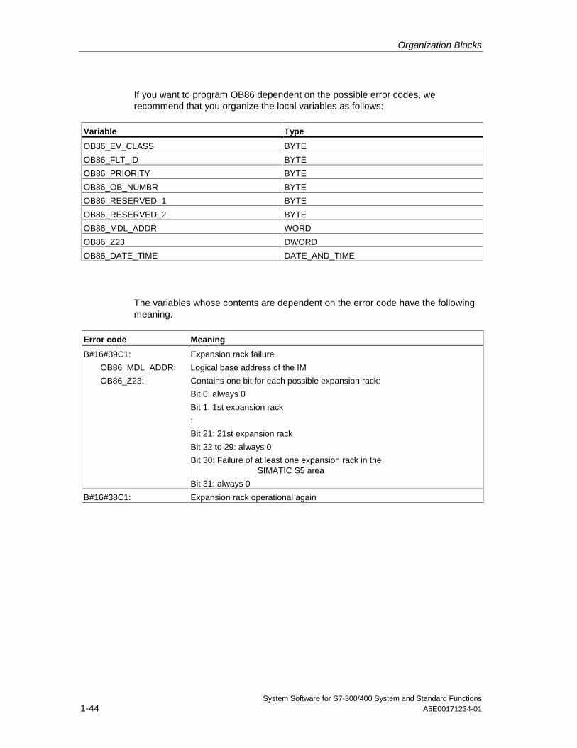
Organization Blocks
System Software for S7-300/400 System and Standard Functions1-44 A5E00171234-01
If you want to program OB86 dependent on the possible error codes, werecommend that you organize the local variables as follows:
Variable Type
OB86_EV_CLASS BYTE
OB86_FLT_ID BYTE
OB86_PRIORITY BYTE
OB86_OB_NUMBR BYTE
OB86_RESERVED_1 BYTE
OB86_RESERVED_2 BYTE
OB86_MDL_ADDR WORD
OB86_Z23 DWORD
OB86_DATE_TIME DATE_AND_TIME
The variables whose contents are dependent on the error code have the followingmeaning:
Error code Meaning
B#16#39C1:
OB86_MDL_ADDR:
OB86_Z23:
Expansion rack failure
Logical base address of the IM
Contains one bit for each possible expansion rack:
Bit 0: always 0
Bit 1: 1st expansion rack
:
Bit 21: 21st expansion rack
Bit 22 to 29: always 0
Bit 30: Failure of at least one expansion rack in theSIMATIC S5 area
Bit 31: always 0
B#16#38C1: Expansion rack operational again
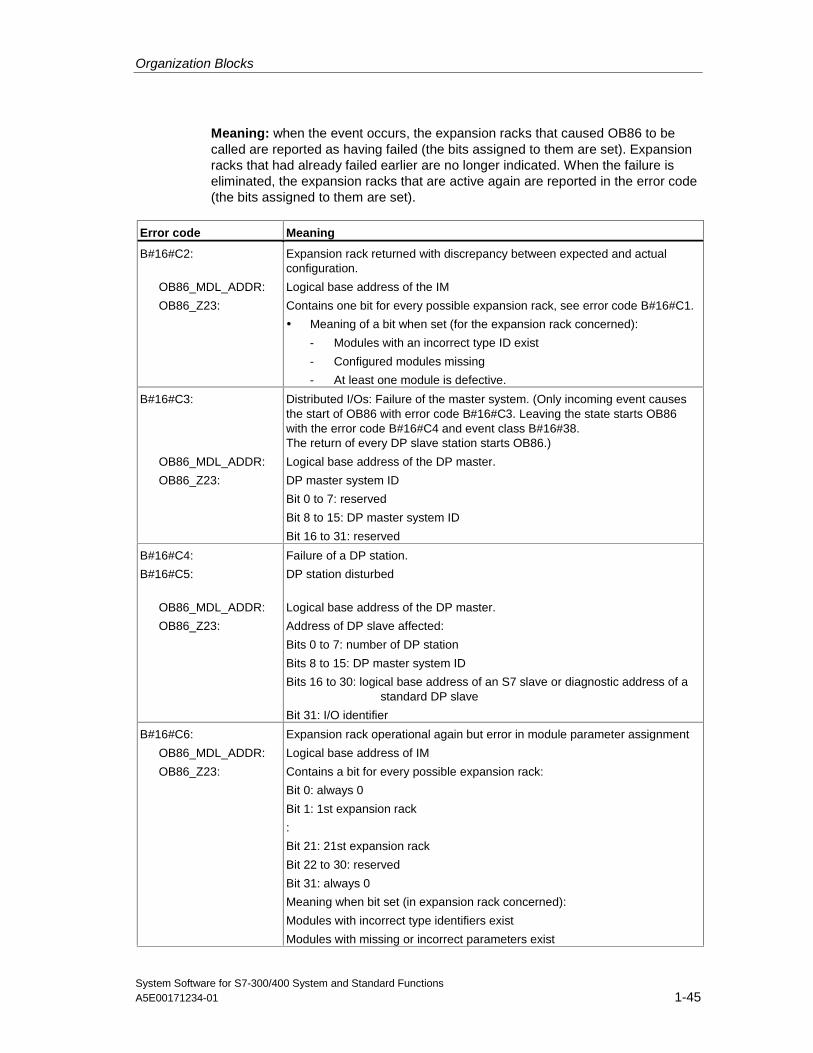
Organization Blocks
System Software for S7-300/400 System and Standard FunctionsA5E00171234-01 1-45
Meaning: when the event occurs, the expansion racks that caused OB86 to becalled are reported as having failed (the bits assigned to them are set). Expansionracks that had already failed earlier are no longer indicated. When the failure iseliminated, the expansion racks that are active again are reported in the error code(the bits assigned to them are set).
Error code Meaning
B#16#C2:
OB86_MDL_ADDR:
OB86_Z23:
Expansion rack returned with discrepancy between expected and actualconfiguration.
Logical base address of the IM
Contains one bit for every possible expansion rack, see error code B#16#C1.
• Meaning of a bit when set (for the expansion rack concerned):
- Modules with an incorrect type ID exist
- Configured modules missing
- At least one module is defective.
B#16#C3:
OB86_MDL_ADDR:
OB86_Z23:
Distributed I/Os: Failure of the master system. (Only incoming event causesthe start of OB86 with error code B#16#C3. Leaving the state starts OB86with the error code B#16#C4 and event class B#16#38.The return of every DP slave station starts OB86.)
Logical base address of the DP master.
DP master system ID
Bit 0 to 7: reserved
Bit 8 to 15: DP master system ID
Bit 16 to 31: reserved
B#16#C4:
B#16#C5:
OB86_MDL_ADDR:
OB86_Z23:
Failure of a DP station.
DP station disturbed
Logical base address of the DP master.
Address of DP slave affected:
Bits 0 to 7: number of DP station
Bits 8 to 15: DP master system ID
Bits 16 to 30: logical base address of an S7 slave or diagnostic address of a standard DP slave
Bit 31: I/O identifier
B#16#C6:
OB86_MDL_ADDR:
OB86_Z23:
Expansion rack operational again but error in module parameter assignment
Logical base address of IM
Contains a bit for every possible expansion rack:
Bit 0: always 0
Bit 1: 1st expansion rack
:
Bit 21: 21st expansion rack
Bit 22 to 30: reserved
Bit 31: always 0
Meaning when bit set (in expansion rack concerned):
Modules with incorrect type identifiers exist
Modules with missing or incorrect parameters exist
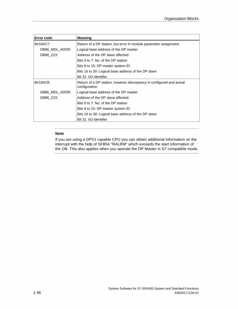
Organization Blocks
System Software for S7-300/400 System and Standard Functions1-46 A5E00171234-01
Error code Meaning
B#16#C7:
OB86_MDL_ADDR:
OB86_Z23:
Return of a DP station, but error in module parameter assignment
Logical base address of the DP master
Address of the DP slave affected:
Bits 0 to 7: No. of the DP station
Bits 8 to 15: DP master system ID
Bits 16 to 30: Logical base address of the DP slave
Bit 31: I/O identifier
B#16#C8:
OB86_MDL_ADDR:
OB86_Z23:
Return of a DP station, however discrepancy in configured and actualconfiguration
Logical base address of the DP master
Address of the DP slave affected:
Bits 0 to 7: No. of the DP station
Bits 8 to 15: DP master system ID
Bits 16 to 30: Logical base address of the DP slave
Bit 31: I/O identifier
Note
If you are using a DPV1 capable CPU you can obtain additional information on theinterrupt with the help of SFB54 "RALRM" which exceeds the start information ofthe OB. This also applies when you operate the DP Master in S7 compatible mode.
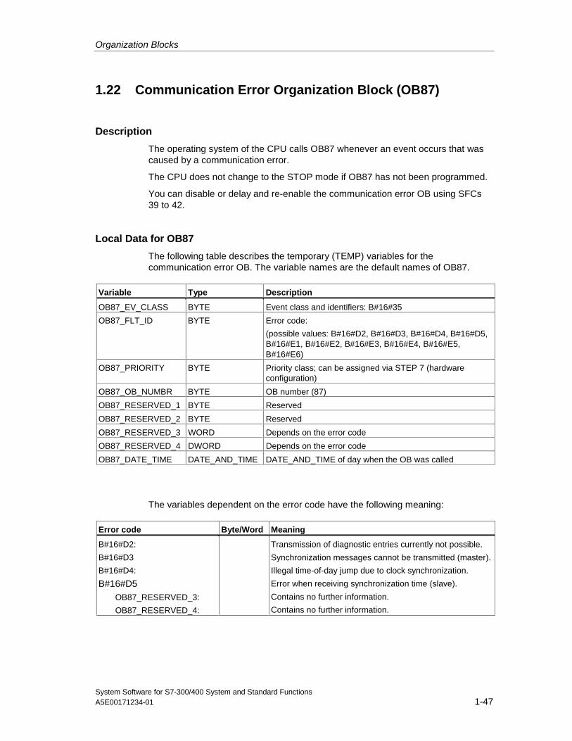
Organization Blocks
System Software for S7-300/400 System and Standard FunctionsA5E00171234-01 1-47
1.22 Communication Error Organization Block (OB87)
Description
The operating system of the CPU calls OB87 whenever an event occurs that wascaused by a communication error.
The CPU does not change to the STOP mode if OB87 has not been programmed.
You can disable or delay and re-enable the communication error OB using SFCs39 to 42.
Local Data for OB87
The following table describes the temporary (TEMP) variables for thecommunication error OB. The variable names are the default names of OB87.
Variable Type Description
OB87_EV_CLASS BYTE Event class and identifiers: B#16#35
OB87_FLT_ID BYTE Error code:
(possible values: B#16#D2, B#16#D3, B#16#D4, B#16#D5,B#16#E1, B#16#E2, B#16#E3, B#16#E4, B#16#E5,B#16#E6)
OB87_PRIORITY BYTE Priority class; can be assigned via STEP 7 (hardwareconfiguration)
OB87_OB_NUMBR BYTE OB number (87)
OB87_RESERVED_1 BYTE Reserved
OB87_RESERVED_2 BYTE Reserved
OB87_RESERVED_3 WORD Depends on the error code
OB87_RESERVED_4 DWORD Depends on the error code
OB87_DATE_TIME DATE_AND_TIME DATE_AND_TIME of day when the OB was called
The variables dependent on the error code have the following meaning:
Error code Byte/Word Meaning
B#16#D2:
B#16#D3
B#16#D4:
B#16#D5OB87_RESERVED_3:
OB87_RESERVED_4:
Transmission of diagnostic entries currently not possible.
Synchronization messages cannot be transmitted (master).
Illegal time-of-day jump due to clock synchronization.
Error when receiving synchronization time (slave).
Contains no further information.
Contains no further information.
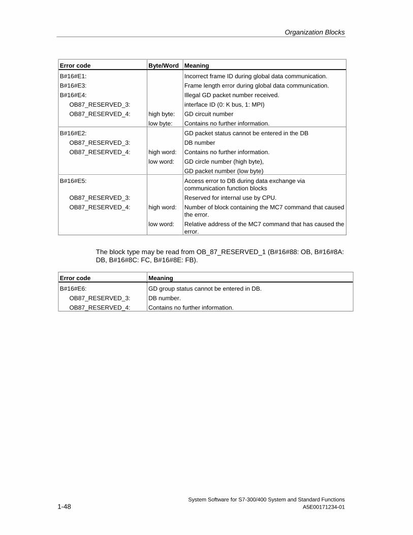
Organization Blocks
System Software for S7-300/400 System and Standard Functions1-48 A5E00171234-01
Error code Byte/Word Meaning
B#16#E1:
B#16#E3:
B#16#E4:
OB87_RESERVED_3:
OB87_RESERVED_4: high byte:
low byte:
Incorrect frame ID during global data communication.
Frame length error during global data communication.
Illegal GD packet number received.
interface ID (0: K bus, 1: MPI)
GD circuit number
Contains no further information.
B#16#E2:
OB87_RESERVED_3:
OB87_RESERVED_4: high word:
low word:
GD packet status cannot be entered in the DB
DB number
Contains no further information.
GD circle number (high byte),
GD packet number (low byte)
B#16#E5:
OB87_RESERVED_3:
OB87_RESERVED_4: high word:
low word:
Access error to DB during data exchange viacommunication function blocks
Reserved for internal use by CPU.
Number of block containing the MC7 command that causedthe error.
Relative address of the MC7 command that has caused theerror.
The block type may be read from OB_87_RESERVED_1 (B#16#88: OB, B#16#8A:DB, B#16#8C: FC, B#16#8E: FB).
Error code Meaning
B#16#E6:
OB87_RESERVED_3:
OB87_RESERVED_4:
GD group status cannot be entered in DB.
DB number.
Contains no further information.
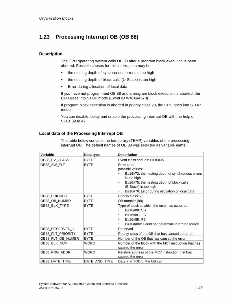
Organization Blocks
System Software for S7-300/400 System and Standard FunctionsA5E00171234-01 1-49
1.23 Processing Interrupt OB (OB 88)
Description
The CPU operating system calls OB 88 after a program block execution is beenaborted. Possible causes for this interruption may be:
• the nesting depth of synchronous errors is too high
• the nesting depth of block calls (U-Stack) is too high
• Error during allocation of local data
If you have not programmed OB 88 and a program block execution is aborted, theCPU goes into STOP mode (Event ID W#16#4570).
If program block execution is aborted in priority class 28, the CPU goes into STOPmode.
You can disable, delay and enable the processing interrupt OB with the help ofSFCs 39 to 42.
Local data of the Processing Interrupt OB
The table below contains the temporary (TEMP) variables of the processinginterrupt OB. The default names of OB 88 was selected as variable name.
Variable Data type Description
OB88_EV_CLASS BYTE Event class and Ids: B#16#35OB88_SW_FLT BYTE Error code
possible values:• B#16#73: the nesting depth of synchronous errors
is too high• B#16#75: the nesting depth of block calls
(B-Stack) is too high• B#16#76: Error during allocation of local data
OB88_PRIORITY BYTE Priority class: 28OB88_OB_NUMBR BYTE OB number (88)OB88_BLK_TYPE BYTE Type of block at which the error has occurred:
• B#16#88: OB• B#16#8C: FC• B#16#8E: FB• B#16##00: Could not determine interrupt source
OB88_RESERVED_1 BYTE ReservedOB88_FLT_PRIORITY BYTE Priority class of the OB that has caused the errorOB88_FLT_OB_NUMBR BYTE Number of the OB that has caused the errorOB88_BLK_NUM WORD Number of the block with the MC7 instruction that has
caused the errorOB88_PRG_ADDR WORD Relative address of the MC7 instruction that has
caused the errorOB88_DATE_TIME DATE_AND_TIME Date and TOD of the OB call
Organization Blocks
System Software for S7-300/400 System and Standard Functions1-50 A5E00171234-01
1.24 Background Organization Block (OB90)
Description
With STEP 7, you can monitor a maximum scan cycle time and can guarantee aminimum scan cycle time. If the execution time of OB1 including all the nestedinterrupts and system activities is less than the minimum scan cycle time that youhave specified, the operating system reacts as follows:
• It calls the background OB (providing it exists on the CPU).
• It delays the next OB1 start (if OB90 does not exist on the CPU).
Understanding the Operation of OB90
OB90 has the lowest priority of all OBs. It is interrupted by any system activity andany interrupt (even by OB1 after the minimum cycle time has elapsed) and is onlyresumed if the selected minimum scan cycle time has not yet been reached. Theone exception to this is the execution of SFCs and SFBs that are started in OB90.These are executed with the priority of OB1 and are therefore not interrupted byOB1. There is no time monitoring of OB90.
The user program in OB90 is processed starting with the first instruction in thefollowing situations:
• Following a warm, cold, or hot restart
• After deleting a block being executed in OB90 (with STEP 7)
• After loading OB90 on the CPU in the RUN mode
• After terminating the background cycle
Note
With configurations in which there is no great difference between the minimumscan cycle time and the cycle monitoring time, SFC and SFB calls in thebackground OB can lead to the cycle time being exceeded unexpectedly.
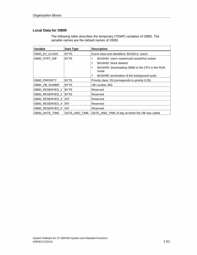
Organization Blocks
System Software for S7-300/400 System and Standard FunctionsA5E00171234-01 1-51
Local Data for OB90
The following table describes the temporary (TEMP) variables of OB90. Thevariable names are the default names of OB90.
Variable Data Type Description
OB90_EV_CLASS BYTE Event class and identifiers: B#16#11: active
OB90_STRT_INF BYTE • B#16#91: warm restart/cold restart/hot restart
• B#16#92: block deleted
• B#16#93: downloading OB90 to the CPU in the RUNmode
• B#16#95: termination of the background cycle
OB90_PRIORITY BYTE Priority class: 29 (corresponds to priority 0.29)
OB90_OB_NUMBR BYTE OB number (90)
OB90_RESERVED_1 BYTE Reserved
OB90_RESERVED_2 BYTE Reserved
OB90_RESERVED_3 INT Reserved
OB90_RESERVED_4 INT Reserved
OB90_RESERVED_5 INT Reserved
OB90_DATE_TIME DATE_AND_TIME DATE_AND_TIME of day at which the OB was called
Organization Blocks
System Software for S7-300/400 System and Standard Functions1-52 A5E00171234-01
1.25 Startup Organization Blocks (OB100, OB101 and OB102)
Types of Startup
A distinction is made between the following types of startup
• Hot restart (not with the S7-300 and the S7-400H)
• Warm restart
• Cold restart
In the following table, you can see which OB is called by the operating systemduring startup.
Type of Startup Corresponding OB
Hot restart OB101
Warm restart OB100
Cold restart OB102
For more detailed information on the types of startup, refer to the manuals"Programming with STEP 7" "Configuring hardware and connections withSTEP7" and "S7-400H PLC."
Startup Events
The CPU executes a startup as follows:
• After POWER ON
• Whenever you switch the mode selector from STOP to RUN-P
• After a request using a communication function (menu command from theprogramming device or by calling the communication function blocks 19"START" or 21 "RESUME" on a different CPU).
• Synchronization in multicomputing
• In an H system after link-up (only on the standby CPU)
Depending on the start event, the particular CPU, and its parameters, theappropriate startup OB (OB100, OB101, or OB102) is called. With suitableprogramming, you can make certain settings for your cyclic program (exception: inan H system, when the standby CPU is linked-up, there is a startup on the standbyCPU but no startup OB is called).
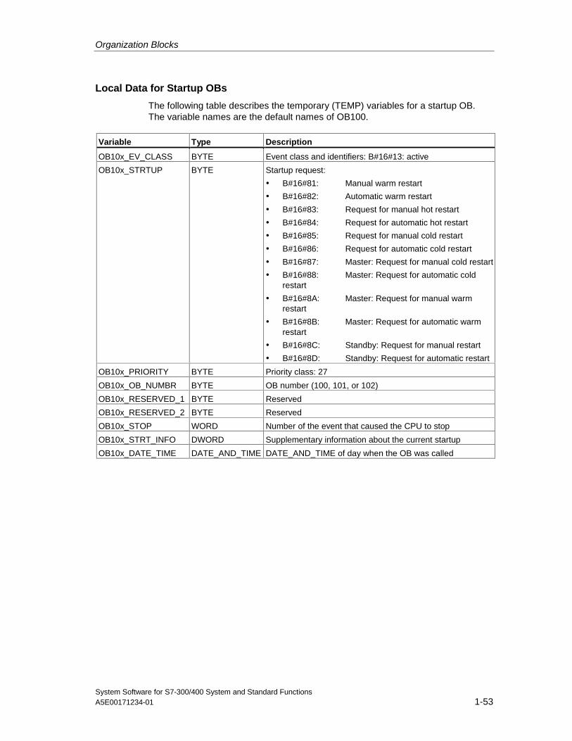
Organization Blocks
System Software for S7-300/400 System and Standard FunctionsA5E00171234-01 1-53
Local Data for Startup OBs
The following table describes the temporary (TEMP) variables for a startup OB.The variable names are the default names of OB100.
Variable Type Description
OB10x_EV_CLASS BYTE Event class and identifiers: B#16#13: active
OB10x_STRTUP BYTE Startup request:
• B#16#81: Manual warm restart
• B#16#82: Automatic warm restart
• B#16#83: Request for manual hot restart
• B#16#84: Request for automatic hot restart
• B#16#85: Request for manual cold restart
• B#16#86: Request for automatic cold restart
• B#16#87: Master: Request for manual cold restart
• B#16#88: Master: Request for automatic coldrestart
• B#16#8A: Master: Request for manual warmrestart
• B#16#8B: Master: Request for automatic warmrestart
• B#16#8C: Standby: Request for manual restart
• B#16#8D: Standby: Request for automatic restart
OB10x_PRIORITY BYTE Priority class: 27
OB10x_OB_NUMBR BYTE OB number (100, 101, or 102)
OB10x_RESERVED_1 BYTE Reserved
OB10x_RESERVED_2 BYTE Reserved
OB10x_STOP WORD Number of the event that caused the CPU to stop
OB10x_STRT_INFO DWORD Supplementary information about the current startup
OB10x_DATE_TIME DATE_AND_TIME DATE_AND_TIME of day when the OB was called
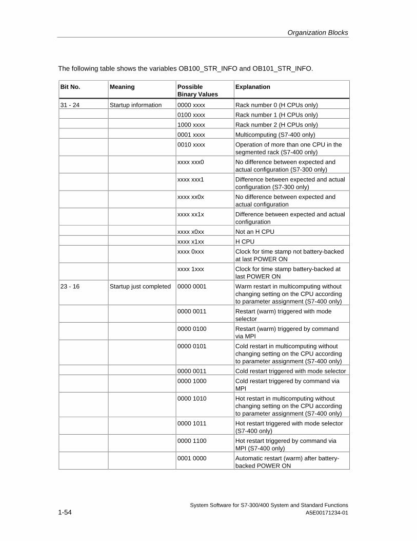
Organization Blocks
System Software for S7-300/400 System and Standard Functions1-54 A5E00171234-01
The following table shows the variables OB100_STR_INFO and OB101_STR_INFO.
Bit No. Meaning PossibleBinary Values
Explanation
31 - 24 Startup information 0000 xxxx Rack number 0 (H CPUs only)
0100 xxxx Rack number 1 (H CPUs only)
1000 xxxx Rack number 2 (H CPUs only)
0001 xxxx Multicomputing (S7-400 only)
0010 xxxx Operation of more than one CPU in thesegmented rack (S7-400 only)
xxxx xxx0 No difference between expected andactual configuration (S7-300 only)
xxxx xxx1 Difference between expected and actualconfiguration (S7-300 only)
xxxx xx0x No difference between expected andactual configuration
xxxx xx1x Difference between expected and actualconfiguration
xxxx x0xx Not an H CPU
xxxx x1xx H CPU
xxxx 0xxx Clock for time stamp not battery-backedat last POWER ON
xxxx 1xxx Clock for time stamp battery-backed atlast POWER ON
23 - 16 Startup just completed 0000 0001 Warm restart in multicomputing withoutchanging setting on the CPU accordingto parameter assignment (S7-400 only)
0000 0011 Restart (warm) triggered with modeselector
0000 0100 Restart (warm) triggered by commandvia MPI
0000 0101 Cold restart in multicomputing withoutchanging setting on the CPU accordingto parameter assignment (S7-400 only)
0000 0011 Cold restart triggered with mode selector
0000 1000 Cold restart triggered by command viaMPI
0000 1010 Hot restart in multicomputing withoutchanging setting on the CPU accordingto parameter assignment (S7-400 only)
0000 1011 Hot restart triggered with mode selector(S7-400 only)
0000 1100 Hot restart triggered by command viaMPI (S7-400 only)
0001 0000 Automatic restart (warm) after battery-backed POWER ON
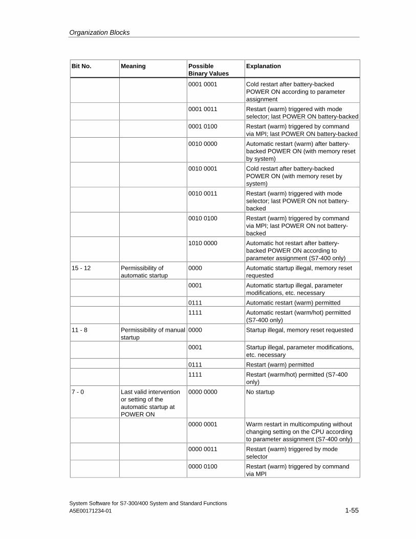
Organization Blocks
System Software for S7-300/400 System and Standard FunctionsA5E00171234-01 1-55
Bit No. Meaning PossibleBinary Values
Explanation
0001 0001 Cold restart after battery-backedPOWER ON according to parameterassignment
0001 0011 Restart (warm) triggered with modeselector; last POWER ON battery-backed
0001 0100 Restart (warm) triggered by commandvia MPI; last POWER ON battery-backed
0010 0000 Automatic restart (warm) after battery-backed POWER ON (with memory resetby system)
0010 0001 Cold restart after battery-backedPOWER ON (with memory reset bysystem)
0010 0011 Restart (warm) triggered with modeselector; last POWER ON not battery-backed
0010 0100 Restart (warm) triggered by commandvia MPI; last POWER ON not battery-backed
1010 0000 Automatic hot restart after battery-backed POWER ON according toparameter assignment (S7-400 only)
15 - 12 Permissibility ofautomatic startup
0000 Automatic startup illegal, memory resetrequested
0001 Automatic startup illegal, parametermodifications, etc. necessary
0111 Automatic restart (warm) permitted
1111 Automatic restart (warm/hot) permitted(S7-400 only)
11 - 8 Permissibility of manualstartup
0000 Startup illegal, memory reset requested
0001 Startup illegal, parameter modifications,etc. necessary
0111 Restart (warm) permitted
1111 Restart (warm/hot) permitted (S7-400only)
7 - 0 Last valid interventionor setting of theautomatic startup atPOWER ON
0000 0000 No startup
0000 0001 Warm restart in multicomputing withoutchanging setting on the CPU accordingto parameter assignment (S7-400 only)
0000 0011 Restart (warm) triggered by modeselector
0000 0100 Restart (warm) triggered by commandvia MPI
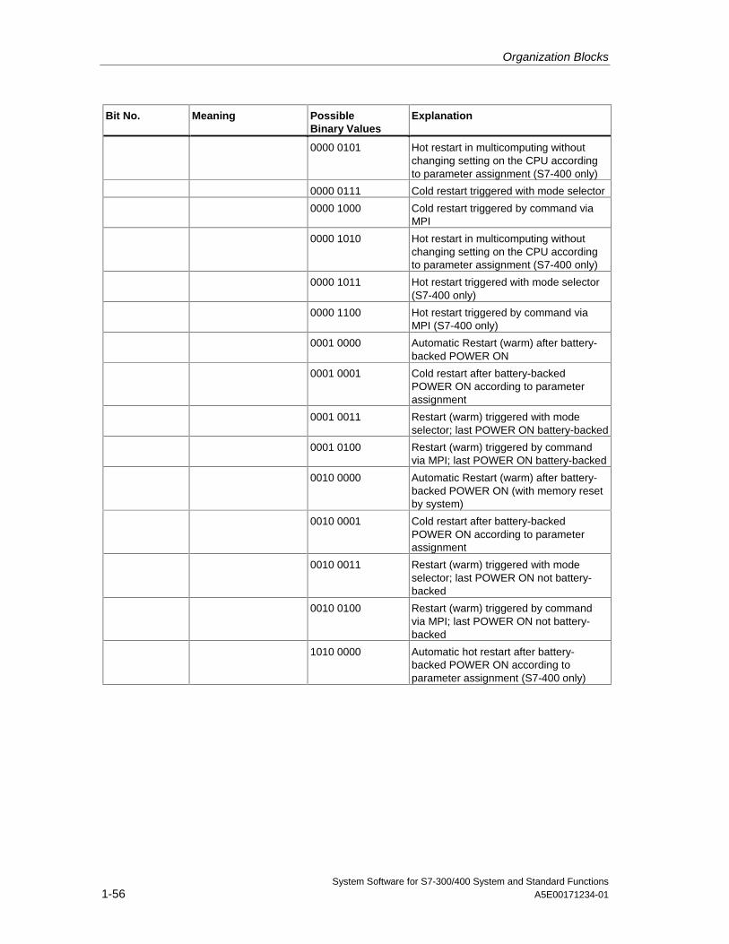
Organization Blocks
System Software for S7-300/400 System and Standard Functions1-56 A5E00171234-01
Bit No. Meaning PossibleBinary Values
Explanation
0000 0101 Hot restart in multicomputing withoutchanging setting on the CPU accordingto parameter assignment (S7-400 only)
0000 0111 Cold restart triggered with mode selector
0000 1000 Cold restart triggered by command viaMPI
0000 1010 Hot restart in multicomputing withoutchanging setting on the CPU accordingto parameter assignment (S7-400 only)
0000 1011 Hot restart triggered with mode selector(S7-400 only)
0000 1100 Hot restart triggered by command viaMPI (S7-400 only)
0001 0000 Automatic Restart (warm) after battery-backed POWER ON
0001 0001 Cold restart after battery-backedPOWER ON according to parameterassignment
0001 0011 Restart (warm) triggered with modeselector; last POWER ON battery-backed
0001 0100 Restart (warm) triggered by commandvia MPI; last POWER ON battery-backed
0010 0000 Automatic Restart (warm) after battery-backed POWER ON (with memory resetby system)
0010 0001 Cold restart after battery-backedPOWER ON according to parameterassignment
0010 0011 Restart (warm) triggered with modeselector; last POWER ON not battery-backed
0010 0100 Restart (warm) triggered by commandvia MPI; last POWER ON not battery-backed
1010 0000 Automatic hot restart after battery-backed POWER ON according toparameter assignment (S7-400 only)
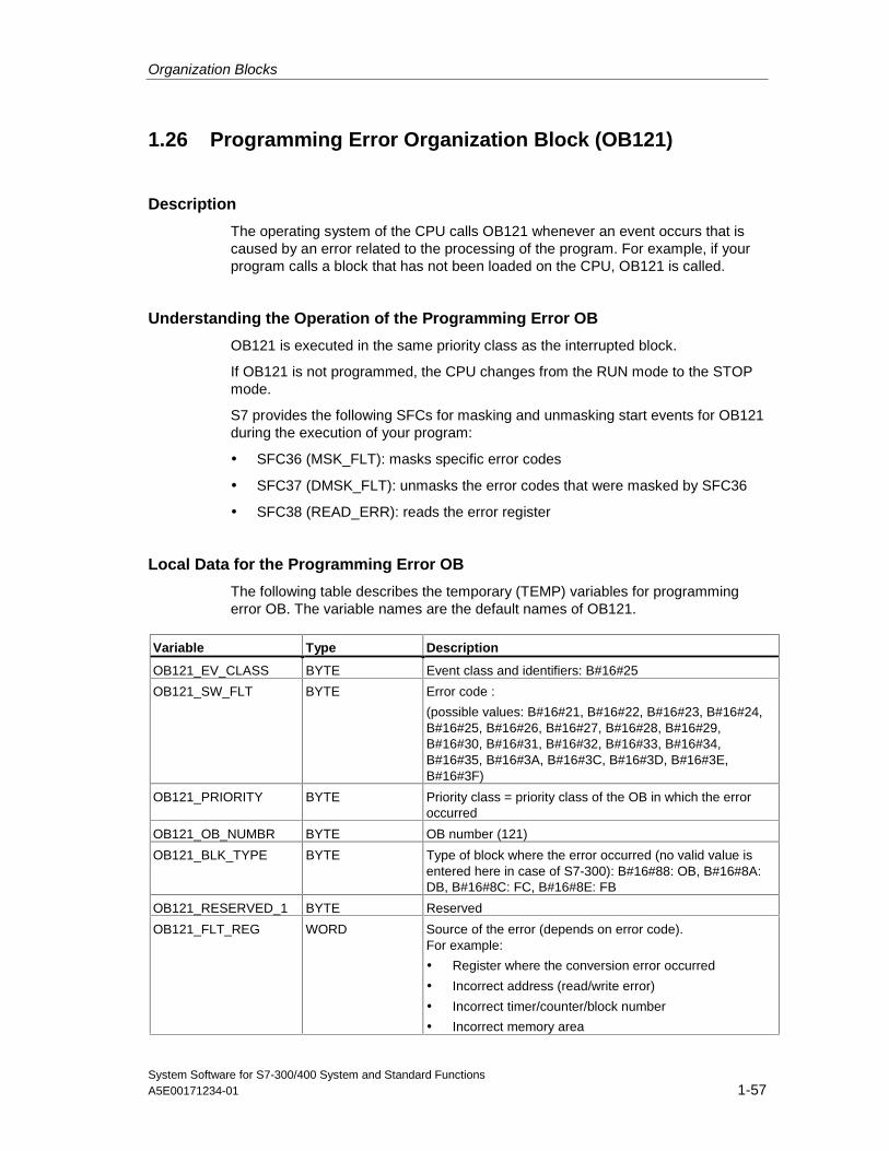
Organization Blocks
System Software for S7-300/400 System and Standard FunctionsA5E00171234-01 1-57
1.26 Programming Error Organization Block (OB121)
Description
The operating system of the CPU calls OB121 whenever an event occurs that iscaused by an error related to the processing of the program. For example, if yourprogram calls a block that has not been loaded on the CPU, OB121 is called.
Understanding the Operation of the Programming Error OB
OB121 is executed in the same priority class as the interrupted block.
If OB121 is not programmed, the CPU changes from the RUN mode to the STOPmode.
S7 provides the following SFCs for masking and unmasking start events for OB121during the execution of your program:
• SFC36 (MSK_FLT): masks specific error codes
• SFC37 (DMSK_FLT): unmasks the error codes that were masked by SFC36
• SFC38 (READ_ERR): reads the error register
Local Data for the Programming Error OB
The following table describes the temporary (TEMP) variables for programmingerror OB. The variable names are the default names of OB121.
Variable Type Description
OB121_EV_CLASS BYTE Event class and identifiers: B#16#25
OB121_SW_FLT BYTE Error code :
(possible values: B#16#21, B#16#22, B#16#23, B#16#24,B#16#25, B#16#26, B#16#27, B#16#28, B#16#29,B#16#30, B#16#31, B#16#32, B#16#33, B#16#34,B#16#35, B#16#3A, B#16#3C, B#16#3D, B#16#3E,B#16#3F)
OB121_PRIORITY BYTE Priority class = priority class of the OB in which the erroroccurred
OB121_OB_NUMBR BYTE OB number (121)
OB121_BLK_TYPE BYTE Type of block where the error occurred (no valid value isentered here in case of S7-300): B#16#88: OB, B#16#8A:DB, B#16#8C: FC, B#16#8E: FB
OB121_RESERVED_1 BYTE Reserved
OB121_FLT_REG WORD Source of the error (depends on error code).For example:
• Register where the conversion error occurred
• Incorrect address (read/write error)
• Incorrect timer/counter/block number
• Incorrect memory area
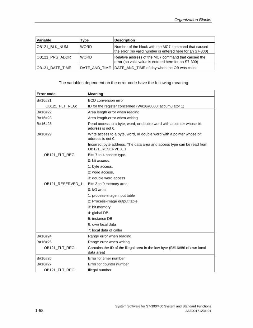
Organization Blocks
System Software for S7-300/400 System and Standard Functions1-58 A5E00171234-01
Variable Type Description
OB121_BLK_NUM WORD Number of the block with the MC7 command that causedthe error (no valid number is entered here for an S7-300)
OB121_PRG_ADDR WORD Relative address of the MC7 command that caused theerror (no valid value is entered here for an S7-300)
OB121_DATE_TIME DATE_AND_TIME DATE_AND_TIME of day when the OB was called
The variables dependent on the error code have the following meaning:
Error code Meaning
B#16#21:
OB121_FLT_REG:
BCD conversion error
ID for the register concerned (W#16#0000: accumulator 1)
B#16#22:
B#16#23:
B#16#28:
B#16#29:
OB121_FLT_REG:
OB121_RESERVED_1:
Area length error when reading
Area length error when writing
Read access to a byte, word, or double word with a pointer whose bitaddress is not 0.
Write access to a byte, word, or double word with a pointer whose bitaddress is not 0.
Incorrect byte address. The data area and access type can be read fromOB121_RESERVED_1.
Bits 7 to 4 access type.
0: bit access,
1: byte access,
2: word access,
3: double word access
Bits 3 to 0 memory area:
0: I/O area
1: process-image input table
2: Process-image output table
3: bit memory
4: global DB
5: instance DB
6: own local data
7: local data of caller
B#16#24:
B#16#25:
OB121_FLT_REG:
Range error when reading
Range error when writing
Contains the ID of the illegal area in the low byte (B#16#86 of own localdata area)
B#16#26:
B#16#27:
OB121_FLT_REG:
Error for timer number
Error for counter number
Illegal number
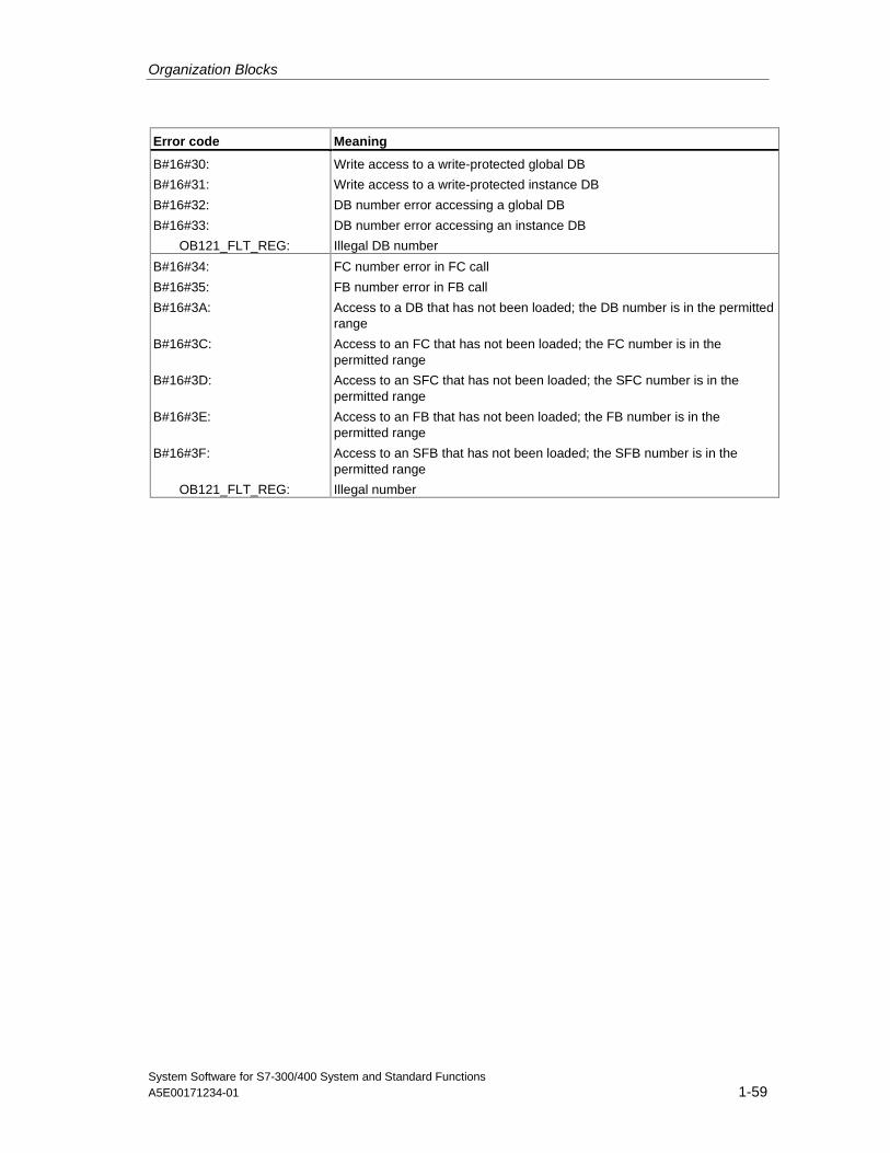
Organization Blocks
System Software for S7-300/400 System and Standard FunctionsA5E00171234-01 1-59
Error code Meaning
B#16#30:
B#16#31:
B#16#32:
B#16#33:
OB121_FLT_REG:
Write access to a write-protected global DB
Write access to a write-protected instance DB
DB number error accessing a global DB
DB number error accessing an instance DB
Illegal DB number
B#16#34:
B#16#35:
B#16#3A:
B#16#3C:
B#16#3D:
B#16#3E:
B#16#3F:
OB121_FLT_REG:
FC number error in FC call
FB number error in FB call
Access to a DB that has not been loaded; the DB number is in the permittedrange
Access to an FC that has not been loaded; the FC number is in thepermitted range
Access to an SFC that has not been loaded; the SFC number is in thepermitted range
Access to an FB that has not been loaded; the FB number is in thepermitted range
Access to an SFB that has not been loaded; the SFB number is in thepermitted range
Illegal number
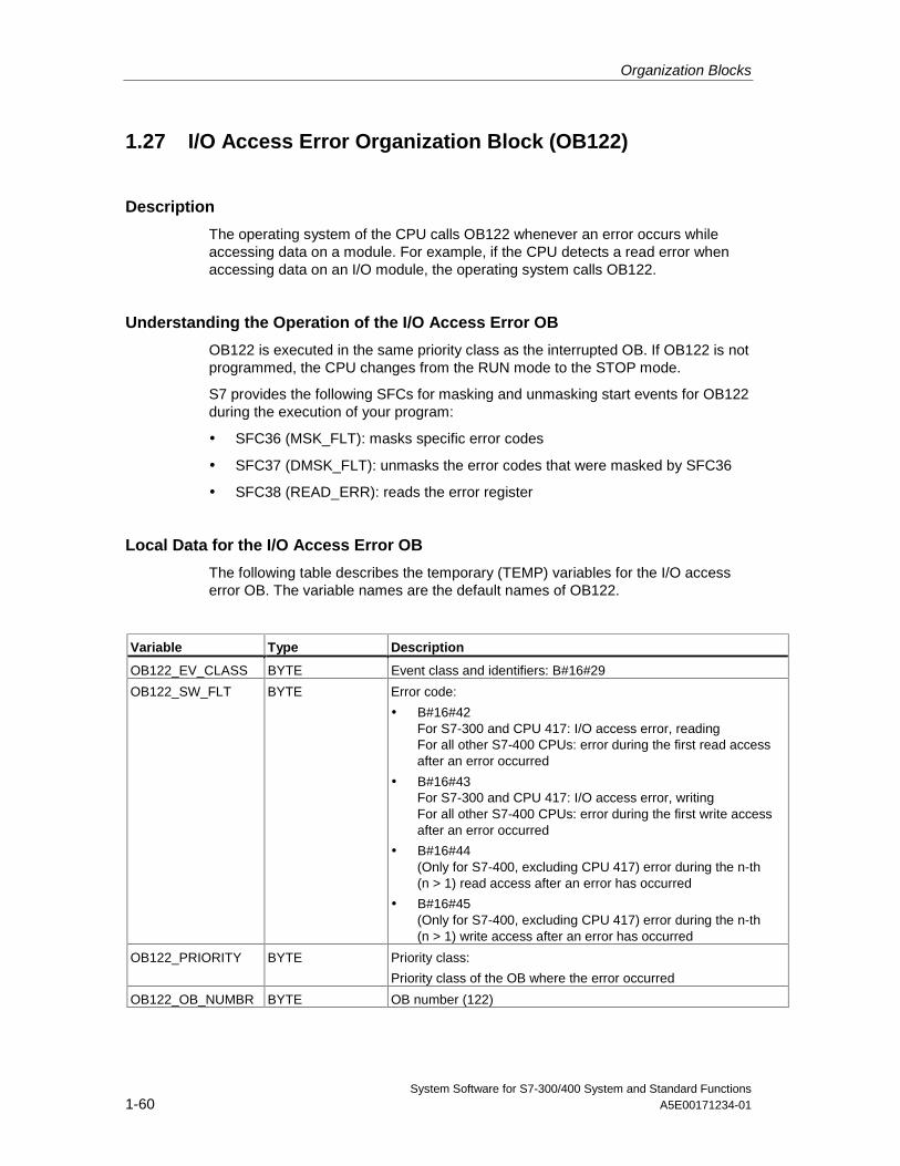
Organization Blocks
System Software for S7-300/400 System and Standard Functions1-60 A5E00171234-01
1.27 I/O Access Error Organization Block (OB122)
Description
The operating system of the CPU calls OB122 whenever an error occurs whileaccessing data on a module. For example, if the CPU detects a read error whenaccessing data on an I/O module, the operating system calls OB122.
Understanding the Operation of the I/O Access Error OB
OB122 is executed in the same priority class as the interrupted OB. If OB122 is notprogrammed, the CPU changes from the RUN mode to the STOP mode.
S7 provides the following SFCs for masking and unmasking start events for OB122during the execution of your program:
• SFC36 (MSK_FLT): masks specific error codes
• SFC37 (DMSK_FLT): unmasks the error codes that were masked by SFC36
• SFC38 (READ_ERR): reads the error register
Local Data for the I/O Access Error OB
The following table describes the temporary (TEMP) variables for the I/O accesserror OB. The variable names are the default names of OB122.
Variable Type Description
OB122_EV_CLASS BYTE Event class and identifiers: B#16#29
OB122_SW_FLT BYTE Error code:
• B#16#42For S7-300 and CPU 417: I/O access error, readingFor all other S7-400 CPUs: error during the first read accessafter an error occurred
• B#16#43For S7-300 and CPU 417: I/O access error, writingFor all other S7-400 CPUs: error during the first write accessafter an error occurred
• B#16#44(Only for S7-400, excluding CPU 417) error during the n-th(n > 1) read access after an error has occurred
• B#16#45(Only for S7-400, excluding CPU 417) error during the n-th(n > 1) write access after an error has occurred
OB122_PRIORITY BYTE Priority class:
Priority class of the OB where the error occurred
OB122_OB_NUMBR BYTE OB number (122)
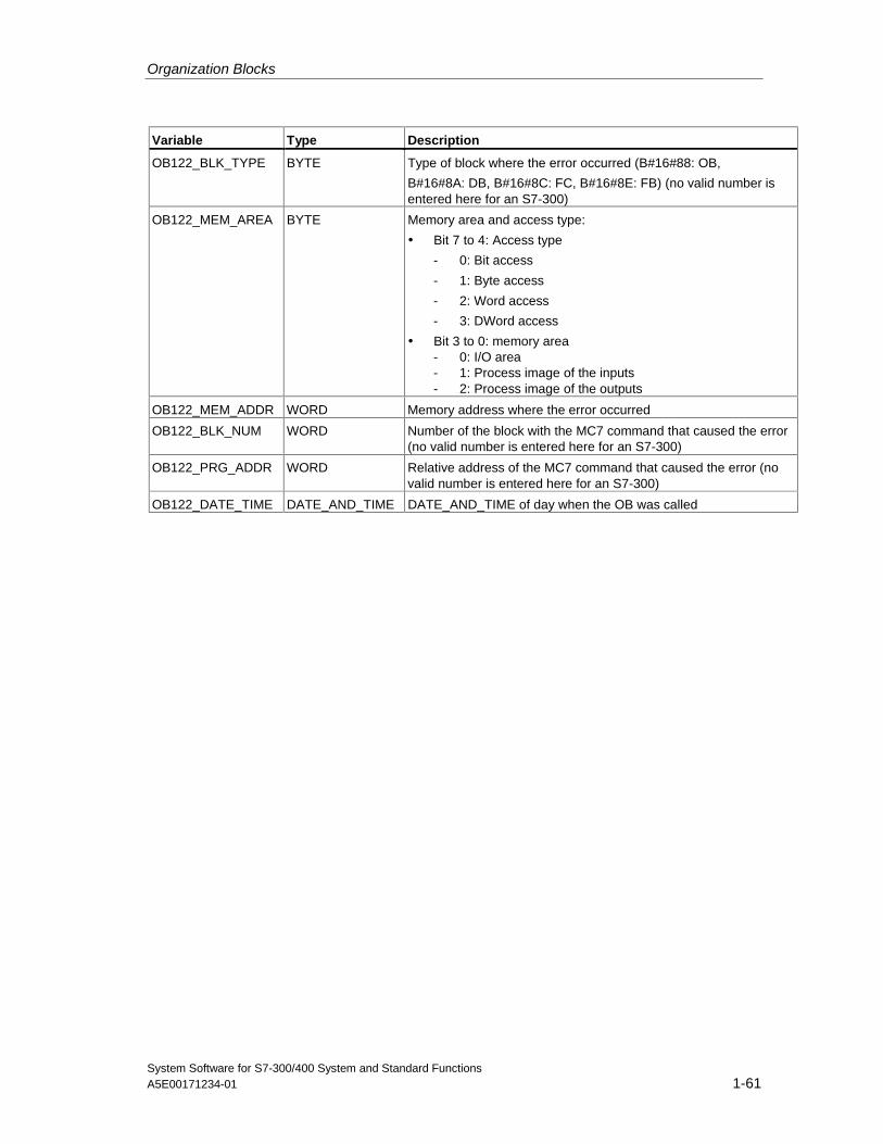
Organization Blocks
System Software for S7-300/400 System and Standard FunctionsA5E00171234-01 1-61
Variable Type Description
OB122_BLK_TYPE BYTE Type of block where the error occurred (B#16#88: OB,
B#16#8A: DB, B#16#8C: FC, B#16#8E: FB) (no valid number isentered here for an S7-300)
OB122_MEM_AREA BYTE Memory area and access type:
• Bit 7 to 4: Access type
- 0: Bit access
- 1: Byte access
- 2: Word access
- 3: DWord access
• Bit 3 to 0: memory area- 0: I/O area- 1: Process image of the inputs- 2: Process image of the outputs
OB122_MEM_ADDR WORD Memory address where the error occurred
OB122_BLK_NUM WORD Number of the block with the MC7 command that caused the error(no valid number is entered here for an S7-300)
OB122_PRG_ADDR WORD Relative address of the MC7 command that caused the error (novalid number is entered here for an S7-300)
OB122_DATE_TIME DATE_AND_TIME DATE_AND_TIME of day when the OB was called

System Software for S7-300/400 System and Standard FunctionsA5E00171234-01 2-1
2 Common Parameters for SFCs
2.1 Evaluating Errors with Output Parameter RET_VAL
Types of Error Information
A system function (SFC) executed in your user program indicates whether or notthe CPU was able to execute the function of the SFC successfully.You can obtain information about any errors that occurred in two ways:
• In the BR bit of the status word
• In the output parameter RET_VAL (return value)
Note
Before evaluating the output parameters specific to an SFC, you should alwaysfollow the steps below:
• First, evaluate the BR bit of the status word.
• Then check the output parameter RET_VAL.
If the BR bit indicates that an error has occurred or if RET_VAL contains a generalerror code, you must not evaluate the SFC output parameter!
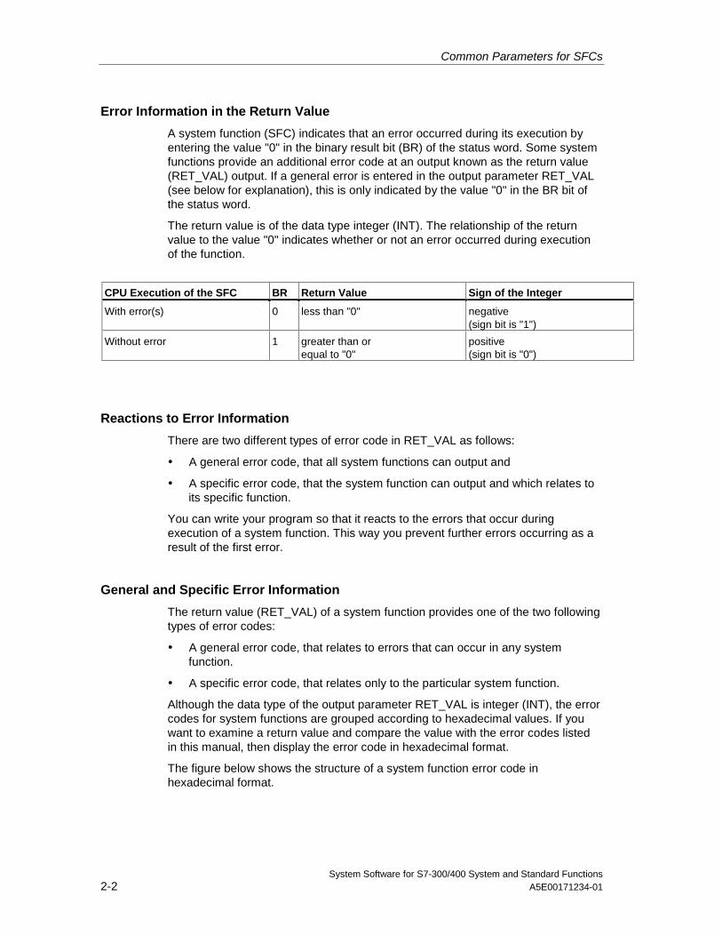
Common Parameters for SFCs
System Software for S7-300/400 System and Standard Functions2-2 A5E00171234-01
Error Information in the Return Value
A system function (SFC) indicates that an error occurred during its execution byentering the value "0" in the binary result bit (BR) of the status word. Some systemfunctions provide an additional error code at an output known as the return value(RET_VAL) output. If a general error is entered in the output parameter RET_VAL(see below for explanation), this is only indicated by the value "0" in the BR bit ofthe status word.
The return value is of the data type integer (INT). The relationship of the returnvalue to the value "0" indicates whether or not an error occurred during executionof the function.
CPU Execution of the SFC BR Return Value Sign of the Integer
With error(s) 0 less than "0" negative(sign bit is "1")
Without error 1 greater than orequal to "0"
positive(sign bit is "0")
Reactions to Error Information
There are two different types of error code in RET_VAL as follows:
• A general error code, that all system functions can output and
• A specific error code, that the system function can output and which relates toits specific function.
You can write your program so that it reacts to the errors that occur duringexecution of a system function. This way you prevent further errors occurring as aresult of the first error.
General and Specific Error Information
The return value (RET_VAL) of a system function provides one of the two followingtypes of error codes:
• A general error code, that relates to errors that can occur in any systemfunction.
• A specific error code, that relates only to the particular system function.
Although the data type of the output parameter RET_VAL is integer (INT), the errorcodes for system functions are grouped according to hexadecimal values. If youwant to examine a return value and compare the value with the error codes listedin this manual, then display the error code in hexadecimal format.
The figure below shows the structure of a system function error code inhexadecimal format.
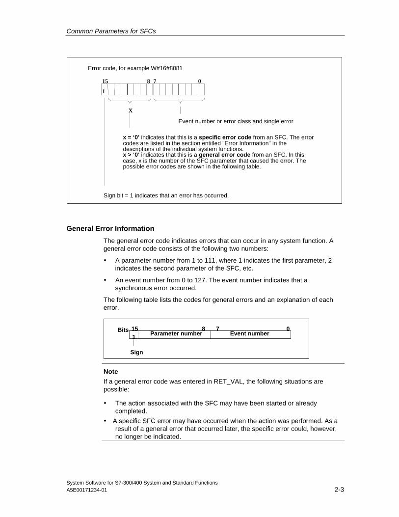
Common Parameters for SFCs
System Software for S7-300/400 System and Standard FunctionsA5E00171234-01 2-3
Error code, for example W#16#8081
Sign bit = 1 indicates that an error has occurred.
15 8 7 0
1
X
Event number or error class and single error
x = ‘0’ indicates that this is a specific error code from an SFC. The errorcodes are listed in the section entitled "Error Information" in thedescriptions of the individual system functions.x > ‘0’ indicates that this is a general error code from an SFC. In thiscase, x is the number of the SFC parameter that caused the error. Thepossible error codes are shown in the following table.
General Error Information
The general error code indicates errors that can occur in any system function. Ageneral error code consists of the following two numbers:
• A parameter number from 1 to 111, where 1 indicates the first parameter, 2indicates the second parameter of the SFC, etc.
• An event number from 0 to 127. The event number indicates that asynchronous error occurred.
The following table lists the codes for general errors and an explanation of eacherror.
07815Bits
Sign
Event numberParameter number1
Note
If a general error code was entered in RET_VAL, the following situations arepossible:
• The action associated with the SFC may have been started or alreadycompleted.
• A specific SFC error may have occurred when the action was performed. As aresult of a general error that occurred later, the specific error could, however,no longer be indicated.
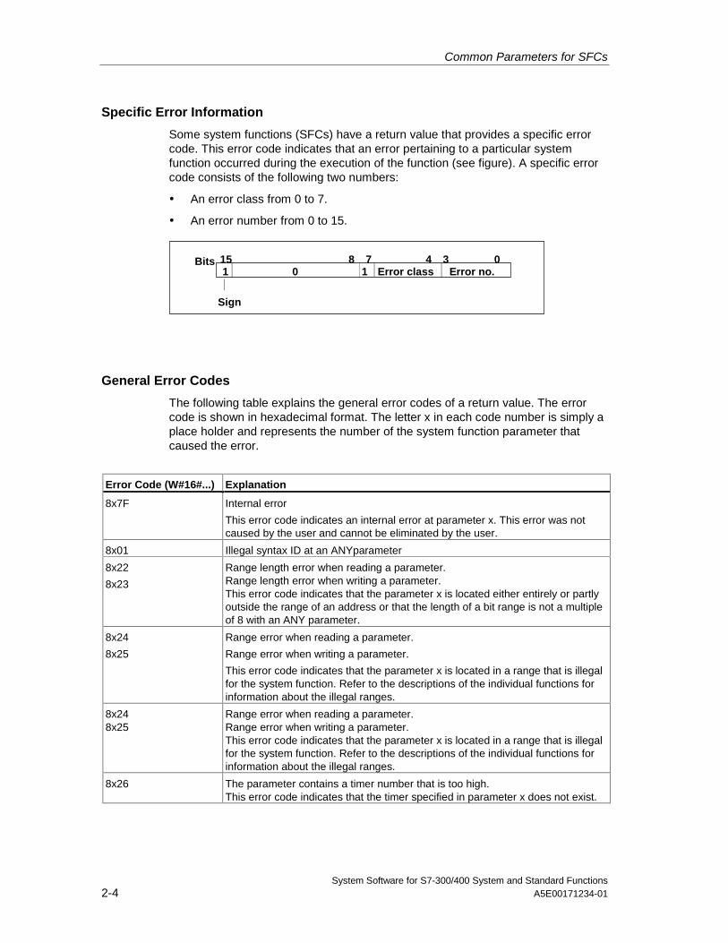
Common Parameters for SFCs
System Software for S7-300/400 System and Standard Functions2-4 A5E00171234-01
Specific Error Information
Some system functions (SFCs) have a return value that provides a specific errorcode. This error code indicates that an error pertaining to a particular systemfunction occurred during the execution of the function (see figure). A specific errorcode consists of the following two numbers:
• An error class from 0 to 7.
• An error number from 0 to 15.
07815Bits
Sign
Error no.Error class134
0 1
General Error Codes
The following table explains the general error codes of a return value. The errorcode is shown in hexadecimal format. The letter x in each code number is simply aplace holder and represents the number of the system function parameter thatcaused the error.
Error Code (W#16#...) Explanation
8x7F Internal error
This error code indicates an internal error at parameter x. This error was notcaused by the user and cannot be eliminated by the user.
8x01 Illegal syntax ID at an ANYparameter
8x22
8x23
Range length error when reading a parameter.Range length error when writing a parameter.This error code indicates that the parameter x is located either entirely or partlyoutside the range of an address or that the length of a bit range is not a multipleof 8 with an ANY parameter.
8x24
8x25
Range error when reading a parameter.
Range error when writing a parameter.
This error code indicates that the parameter x is located in a range that is illegalfor the system function. Refer to the descriptions of the individual functions forinformation about the illegal ranges.
8x248x25
Range error when reading a parameter.Range error when writing a parameter.This error code indicates that the parameter x is located in a range that is illegalfor the system function. Refer to the descriptions of the individual functions forinformation about the illegal ranges.
8x26 The parameter contains a timer number that is too high.This error code indicates that the timer specified in parameter x does not exist.
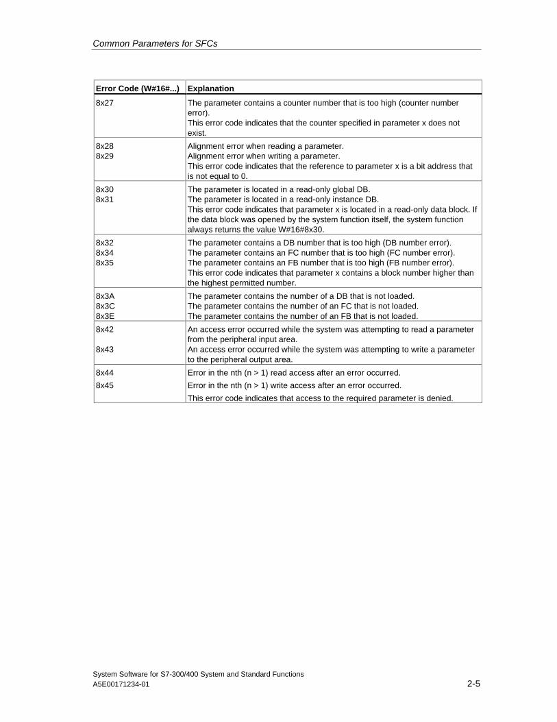
Common Parameters for SFCs
System Software for S7-300/400 System and Standard FunctionsA5E00171234-01 2-5
Error Code (W#16#...) Explanation
8x27 The parameter contains a counter number that is too high (counter numbererror).This error code indicates that the counter specified in parameter x does notexist.
8x288x29
Alignment error when reading a parameter.Alignment error when writing a parameter.This error code indicates that the reference to parameter x is a bit address thatis not equal to 0.
8x308x31
The parameter is located in a read-only global DB.The parameter is located in a read-only instance DB.This error code indicates that parameter x is located in a read-only data block. Ifthe data block was opened by the system function itself, the system functionalways returns the value W#16#8x30.
8x328x348x35
The parameter contains a DB number that is too high (DB number error).The parameter contains an FC number that is too high (FC number error).The parameter contains an FB number that is too high (FB number error).This error code indicates that parameter x contains a block number higher thanthe highest permitted number.
8x3A8x3C8x3E
The parameter contains the number of a DB that is not loaded.The parameter contains the number of an FC that is not loaded.The parameter contains the number of an FB that is not loaded.
8x42
8x43
An access error occurred while the system was attempting to read a parameterfrom the peripheral input area.An access error occurred while the system was attempting to write a parameterto the peripheral output area.
8x44
8x45
Error in the nth (n > 1) read access after an error occurred.
Error in the nth (n > 1) write access after an error occurred.
This error code indicates that access to the required parameter is denied.
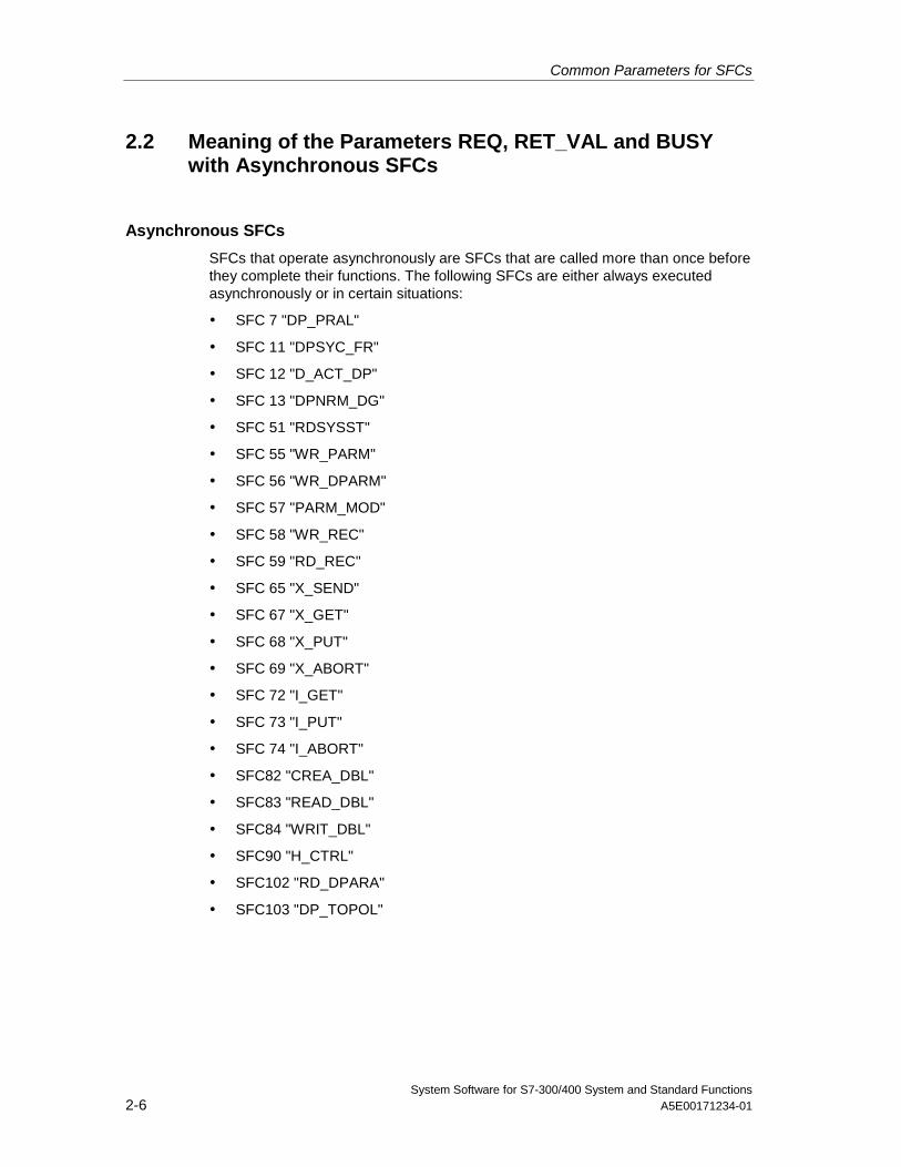
Common Parameters for SFCs
System Software for S7-300/400 System and Standard Functions2-6 A5E00171234-01
2.2 Meaning of the Parameters REQ, RET_VAL and BUSYwith Asynchronous SFCs
Asynchronous SFCs
SFCs that operate asynchronously are SFCs that are called more than once beforethey complete their functions. The following SFCs are either always executedasynchronously or in certain situations:
• SFC 7 "DP_PRAL"
• SFC 11 "DPSYC_FR"
• SFC 12 "D_ACT_DP"
• SFC 13 "DPNRM_DG"
• SFC 51 "RDSYSST"
• SFC 55 "WR_PARM"
• SFC 56 "WR_DPARM"
• SFC 57 "PARM_MOD"
• SFC 58 "WR_REC"
• SFC 59 "RD_REC"
• SFC 65 "X_SEND"
• SFC 67 "X_GET"
• SFC 68 "X_PUT"
• SFC 69 "X_ABORT"
• SFC 72 "I_GET"
• SFC 73 "I_PUT"
• SFC 74 "I_ABORT"
• SFC82 "CREA_DBL"
• SFC83 "READ_DBL"
• SFC84 "WRIT_DBL"
• SFC90 "H_CTRL"
• SFC102 "RD_DPARA"
• SFC103 "DP_TOPOL"
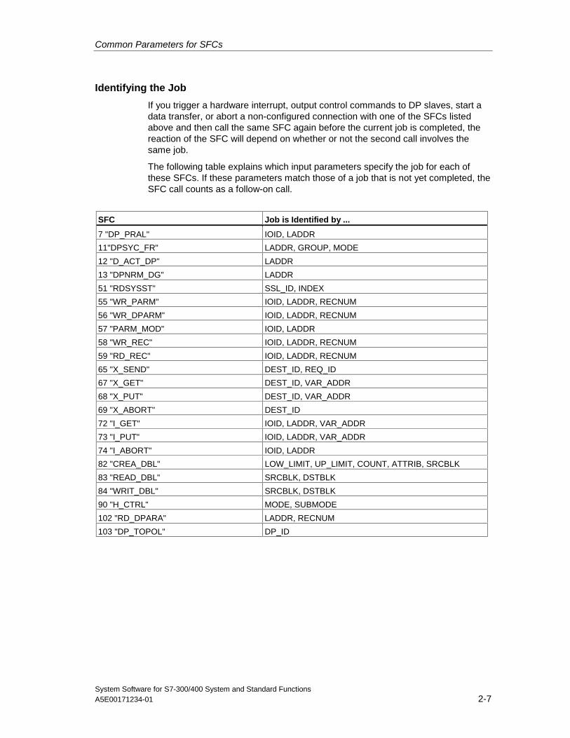
Common Parameters for SFCs
System Software for S7-300/400 System and Standard FunctionsA5E00171234-01 2-7
Identifying the Job
If you trigger a hardware interrupt, output control commands to DP slaves, start adata transfer, or abort a non-configured connection with one of the SFCs listedabove and then call the same SFC again before the current job is completed, thereaction of the SFC will depend on whether or not the second call involves thesame job.
The following table explains which input parameters specify the job for each ofthese SFCs. If these parameters match those of a job that is not yet completed, theSFC call counts as a follow-on call.
SFC Job is Identified by ...
7 "DP_PRAL" IOID, LADDR
11"DPSYC_FR" LADDR, GROUP, MODE
12 "D_ACT_DP" LADDR
13 "DPNRM_DG" LADDR
51 "RDSYSST" SSL_ID, INDEX
55 "WR_PARM" IOID, LADDR, RECNUM
56 "WR_DPARM" IOID, LADDR, RECNUM
57 "PARM_MOD" IOID, LADDR
58 "WR_REC" IOID, LADDR, RECNUM
59 "RD_REC" IOID, LADDR, RECNUM
65 "X_SEND" DEST_ID, REQ_ID
67 "X_GET" DEST_ID, VAR_ADDR
68 "X_PUT" DEST_ID, VAR_ADDR
69 "X_ABORT" DEST_ID
72 "I_GET" IOID, LADDR, VAR_ADDR
73 "I_PUT" IOID, LADDR, VAR_ADDR
74 "I_ABORT" IOID, LADDR
82 "CREA_DBL" LOW_LIMIT, UP_LIMIT, COUNT, ATTRIB, SRCBLK
83 "READ_DBL" SRCBLK, DSTBLK
84 "WRIT_DBL" SRCBLK, DSTBLK
90 "H_CTRL" MODE, SUBMODE
102 "RD_DPARA" LADDR, RECNUM
103 "DP_TOPOL" DP_ID
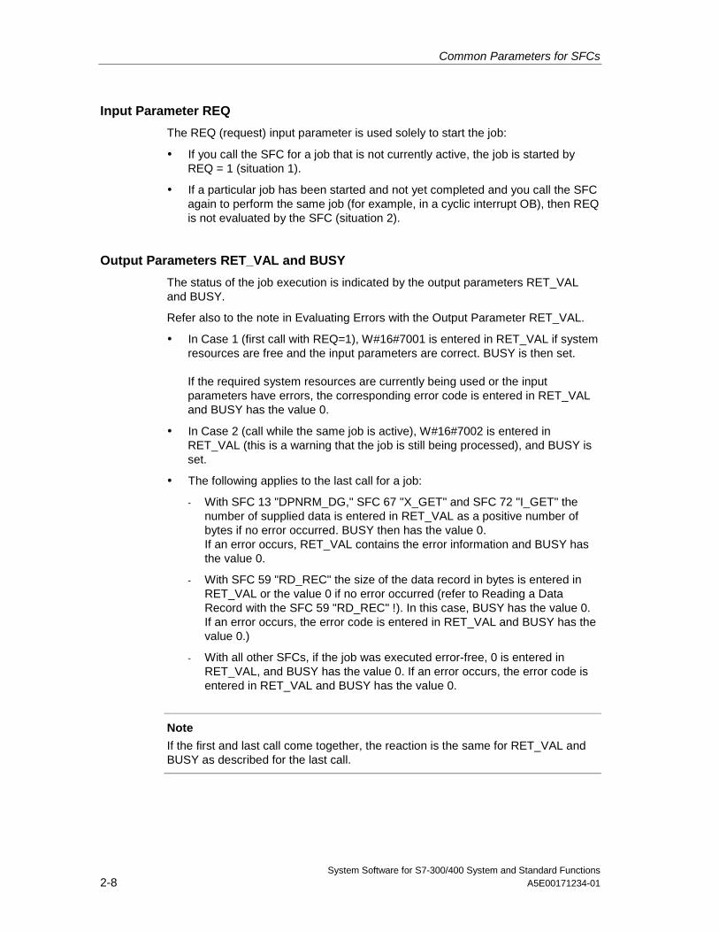
Common Parameters for SFCs
System Software for S7-300/400 System and Standard Functions2-8 A5E00171234-01
Input Parameter REQ
The REQ (request) input parameter is used solely to start the job:
• If you call the SFC for a job that is not currently active, the job is started byREQ = 1 (situation 1).
• If a particular job has been started and not yet completed and you call the SFCagain to perform the same job (for example, in a cyclic interrupt OB), then REQis not evaluated by the SFC (situation 2).
Output Parameters RET_VAL and BUSY
The status of the job execution is indicated by the output parameters RET_VALand BUSY.
Refer also to the note in Evaluating Errors with the Output Parameter RET_VAL.
• In Case 1 (first call with REQ=1), W#16#7001 is entered in RET_VAL if systemresources are free and the input parameters are correct. BUSY is then set.
If the required system resources are currently being used or the inputparameters have errors, the corresponding error code is entered in RET_VALand BUSY has the value 0.
• In Case 2 (call while the same job is active), W#16#7002 is entered inRET_VAL (this is a warning that the job is still being processed), and BUSY isset.
• The following applies to the last call for a job:
- With SFC 13 "DPNRM_DG," SFC 67 "X_GET" and SFC 72 "I_GET" thenumber of supplied data is entered in RET_VAL as a positive number ofbytes if no error occurred. BUSY then has the value 0.If an error occurs, RET_VAL contains the error information and BUSY hasthe value 0.
- With SFC 59 "RD_REC" the size of the data record in bytes is entered inRET_VAL or the value 0 if no error occurred (refer to Reading a DataRecord with the SFC 59 "RD_REC" !). In this case, BUSY has the value 0.If an error occurs, the error code is entered in RET_VAL and BUSY has thevalue 0.)
- With all other SFCs, if the job was executed error-free, 0 is entered inRET_VAL, and BUSY has the value 0. If an error occurs, the error code isentered in RET_VAL and BUSY has the value 0.
Note
If the first and last call come together, the reaction is the same for RET_VAL andBUSY as described for the last call.
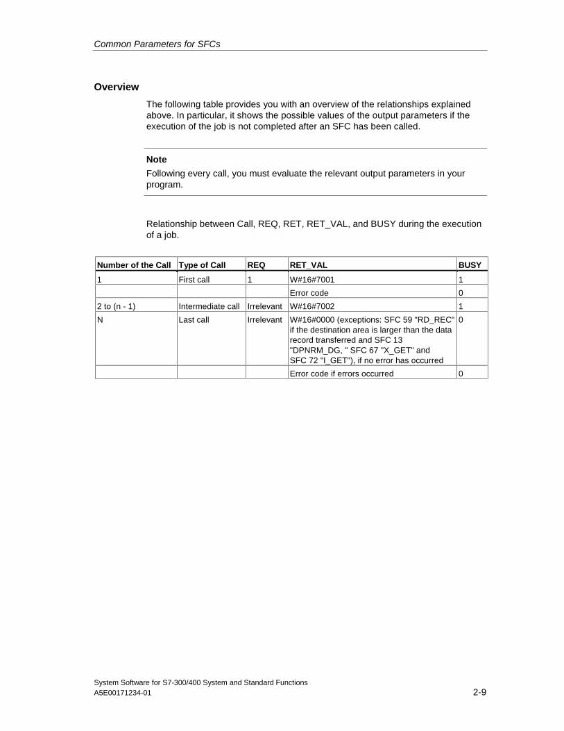
Common Parameters for SFCs
System Software for S7-300/400 System and Standard FunctionsA5E00171234-01 2-9
Overview
The following table provides you with an overview of the relationships explainedabove. In particular, it shows the possible values of the output parameters if theexecution of the job is not completed after an SFC has been called.
Note
Following every call, you must evaluate the relevant output parameters in yourprogram.
Relationship between Call, REQ, RET, RET_VAL, and BUSY during the executionof a job.
Number of the Call Type of Call REQ RET_VAL BUSY
1 First call 1 W#16#7001 1
Error code 0
2 to (n - 1) Intermediate call Irrelevant W#16#7002 1
N Last call Irrelevant W#16#0000 (exceptions: SFC 59 "RD_REC"if the destination area is larger than the datarecord transferred and SFC 13"DPNRM_DG, " SFC 67 "X_GET" andSFC 72 "I_GET"), if no error has occurred
0
Error code if errors occurred 0

Common Parameters for SFCs
System Software for S7-300/400 System and Standard Functions2-10 A5E00171234-01
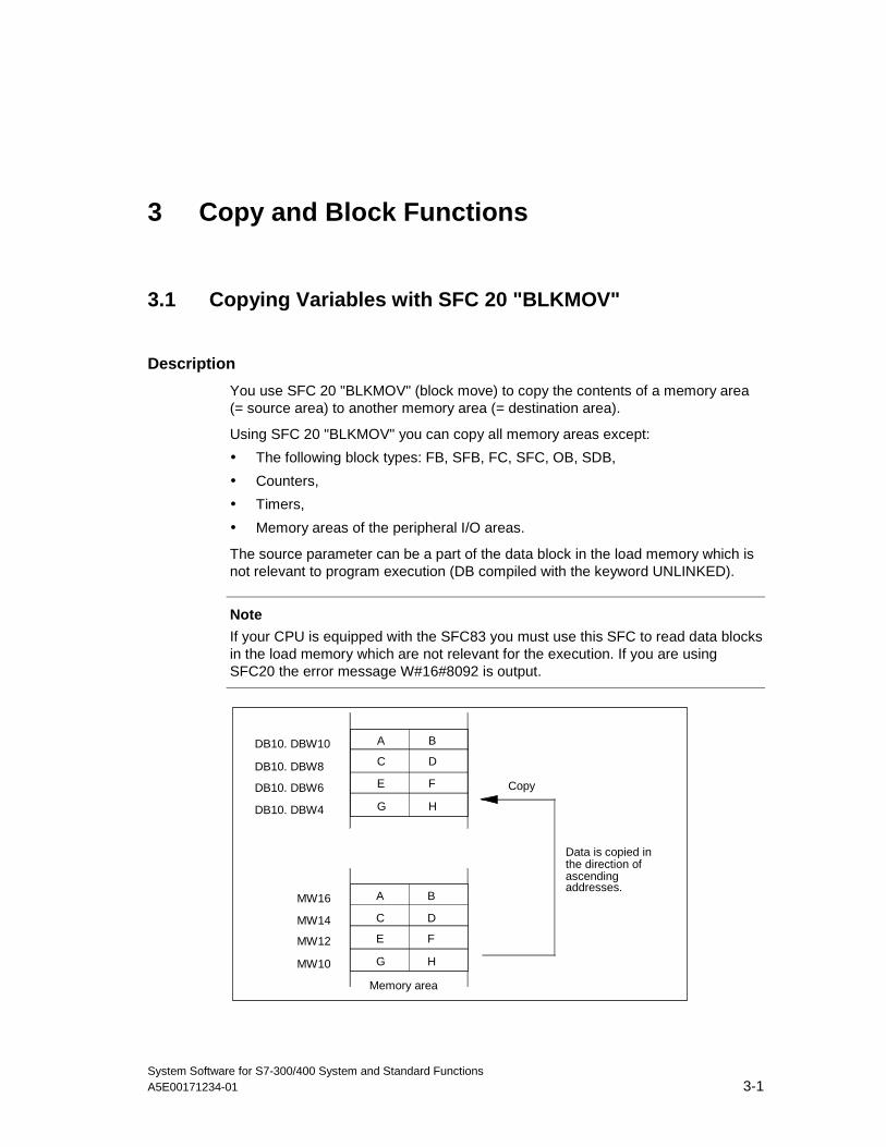
System Software for S7-300/400 System and Standard FunctionsA5E00171234-01 3-1
3 Copy and Block Functions
3.1 Copying Variables with SFC 20 "BLKMOV"
Description
You use SFC 20 "BLKMOV" (block move) to copy the contents of a memory area(= source area) to another memory area (= destination area).
Using SFC 20 "BLKMOV" you can copy all memory areas except:
• The following block types: FB, SFB, FC, SFC, OB, SDB,
• Counters,
• Timers,
• Memory areas of the peripheral I/O areas.
The source parameter can be a part of the data block in the load memory which isnot relevant to program execution (DB compiled with the keyword UNLINKED).
Note
If your CPU is equipped with the SFC83 you must use this SFC to read data blocksin the load memory which are not relevant for the execution. If you are usingSFC20 the error message W#16#8092 is output.
A B
C D
E F
G H
A B
C D
E F
G H
DB10. DBW10
DB10. DBW8
DB10. DBW6
DB10. DBW4
MW16
MW14
MW12
MW10
Data is copied inthe direction ofascendingaddresses.
Memory area
Copy
Copy and Block Functions
System Software for S7-300/400 System and Standard Functions3-2 A5E00171234-01
Interrupt ability
As long as the source area is not part of a data block that only exists in the loadmemory, there is no limit to the nesting depth.
If, however, SFC 20 is interrupted while copying from a DB that is not relevant toprogram execution, the execution of SFC 20 can no longer be nested.
Parameter Declaration Data Type MemoryArea
Description
SRCBLK INPUT ANY I, Q, M, D, L Specifies the memory area to be copied (sourcearea). Arrays of the data type STRING are notpermitted.
RET_VAL OUTPUT INT I, Q, M, D, L If an error occurs when the function is beingexecuted, the return value contains an error code.
DSTBLK OUTPUT ANY I, Q, M, D, L Specifies the memory area to which the data willbe copied (destination area). Arrays of the datatype STRING are not permitted.
Note
The source and destination areas must not overlap. If the specified destinationarea is larger than the source area, the function only copies as much data to thedestination area as is contained in the source area.
If the specified destination area is smaller than the source area, the function onlycopies as much data as can be written to the destination area.
If the ANY pointer (source or destination) is of the type BOOL, the length specifiedmust be divisible by 8; otherwise the SFC will not be executed.
Source or destination parameters (or both) should also be STRING data types. Ifthe source is a string, only the current characters in the string will be copied. If thedestination is a string, the current length of the number of copied characters will bewritten. No ARRAY OF STRING can be copied. This means that only "STRING 1"is permissible.
Special feature: If an unlinked data block is copied to the RAM with SFC 20BLKMOV and loaded at the same time, for example, through the programmingdevice, the SFC can be delayed up to several milliseconds. This results in a longerOB cycle and may alert the cycle monitoring. Avoid loading the block during thetime in which the CPU is copying this block with SFC 20.
Error Information
Error Code(W#16#...)
Explanation
0000 No error
8091 Nesting depth exceeded.
The source area does not lie in the execution-relevant data block.
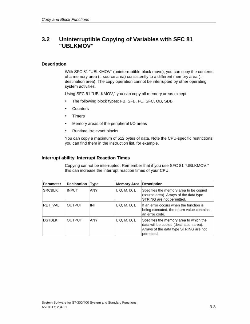
Copy and Block Functions
System Software for S7-300/400 System and Standard FunctionsA5E00171234-01 3-3
3.2 Uninterruptible Copying of Variables with SFC 81"UBLKMOV"
Description
With SFC 81 "UBLKMOV" (uninterruptible block move), you can copy the contentsof a memory area (= source area) consistently to a different memory area (=destination area). The copy operation cannot be interrupted by other operatingsystem activities.
Using SFC 81 "UBLKMOV," you can copy all memory areas except:
• The following block types: FB, SFB, FC, SFC, OB, SDB
• Counters
• Timers
• Memory areas of the peripheral I/O areas
• Runtime irrelevant blocks
You can copy a maximum of 512 bytes of data. Note the CPU-specific restrictions;you can find them in the instruction list, for example.
Interrupt ability, Interrupt Reaction Times
Copying cannot be interrupted. Remember that if you use SFC 81 "UBLKMOV,"this can increase the interrupt reaction times of your CPU.
Parameter Declaration Type Memory Area Description
SRCBLK INPUT ANY I, Q, M, D, L Specifies the memory area to be copied(source area). Arrays of the data typeSTRING are not permitted.
RET_VAL OUTPUT INT I, Q, M, D, L If an error occurs when the function isbeing executed, the return value containsan error code.
DSTBLK OUTPUT ANY I, Q, M, D, L Specifies the memory area to which thedata will be copied (destination area).Arrays of the data type STRING are notpermitted.
Copy and Block Functions
System Software for S7-300/400 System and Standard Functions3-4 A5E00171234-01
Note
The source and destination areas must not overlap. If the specified destinationarea is larger than the source area, the function only copies as much data to thedestination area as is contained in the source area.
If the specified destination area is smaller than the source area, the function onlycopies as much data as can be written to the destination area.
If the ANY pointer (source or destination) is of the type BOOL, the length specifiedmust be divisible by 8; otherwise the SFC will not be executed.
If the ANY pointer is of the type STRING, the length specified must be 1.
Error Information
Error Code (W#16#...) Description
0000 No error
8091 The source area is in an unlinked data block.
8092 The "Copy Variable " operation cannot be carried out because of access to adata block that is not executable. Here, use the SFC83.
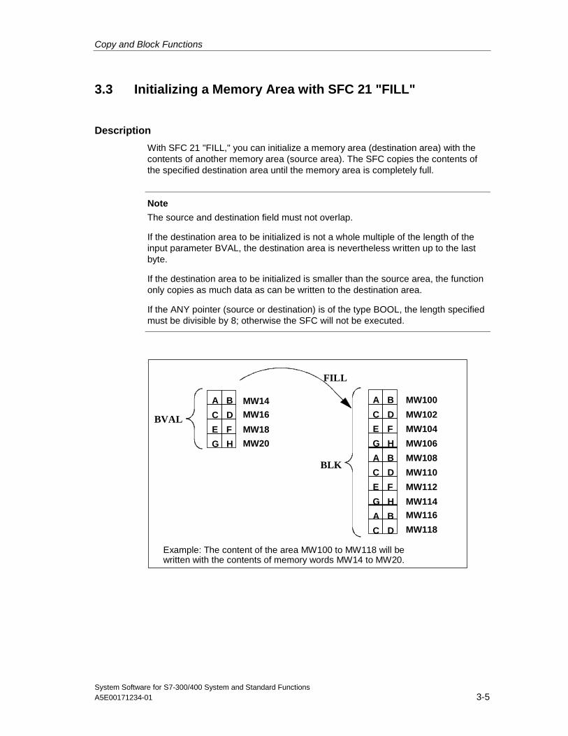
Copy and Block Functions
System Software for S7-300/400 System and Standard FunctionsA5E00171234-01 3-5
3.3 Initializing a Memory Area with SFC 21 "FILL"
Description
With SFC 21 "FILL," you can initialize a memory area (destination area) with thecontents of another memory area (source area). The SFC copies the contents ofthe specified destination area until the memory area is completely full.
Note
The source and destination field must not overlap.
If the destination area to be initialized is not a whole multiple of the length of theinput parameter BVAL, the destination area is nevertheless written up to the lastbyte.
If the destination area to be initialized is smaller than the source area, the functiononly copies as much data as can be written to the destination area.
If the ANY pointer (source or destination) is of the type BOOL, the length specifiedmust be divisible by 8; otherwise the SFC will not be executed.
A B
C D
E F
G H
A B
C D
E F
G H
A B
C D
E F
G H
A B
C D
MW14
MW16
MW18
MW20
MW100
MW102
MW104
MW106
MW108
MW110
MW112
MW114MW116
MW118
BVAL
BLK
FILL
Example: The content of the area MW100 to MW118 will bewritten with the contents of memory words MW14 to MW20.
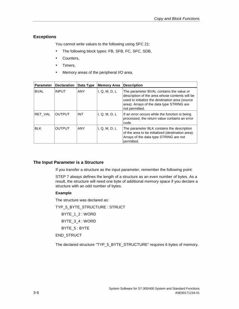
Copy and Block Functions
System Software for S7-300/400 System and Standard Functions3-6 A5E00171234-01
Exceptions
You cannot write values to the following using SFC 21:
• The following block types: FB, SFB, FC, SFC, SDB,
• Counters,
• Timers,
• Memory areas of the peripheral I/O area.
Parameter Declaration Data Type Memory Area Description
BVAL INPUT ANY I, Q, M, D, L The parameter BVAL contains the value ordescription of the area whose contents will beused to initialize the destination area (sourcearea). Arrays of the data type STRING arenot permitted.
RET_VAL OUTPUT INT I, Q, M, D, L If an error occurs while the function is beingprocessed, the return value contains an errorcode.
BLK OUTPUT ANY I, Q, M, D, L The parameter BLK contains the descriptionof the area to be initialized (destination area).Arrays of the data type STRING are notpermitted.
The Input Parameter is a Structure
If you transfer a structure as the input parameter, remember the following point:
STEP 7 always defines the length of a structure as an even number of bytes. As aresult, the structure will need one byte of additional memory space if you declare astructure with an odd number of bytes.
Example
The structure was declared as:
TYP_5_BYTE_STRUCTURE : STRUCT
BYTE_1_2 : WORD
BYTE_3_4 : WORD
BYTE_5 : BYTE
END_STRUCT
The declared structure "TYP_5_BYTE_STRUCTURE" requires 6 bytes of memory.
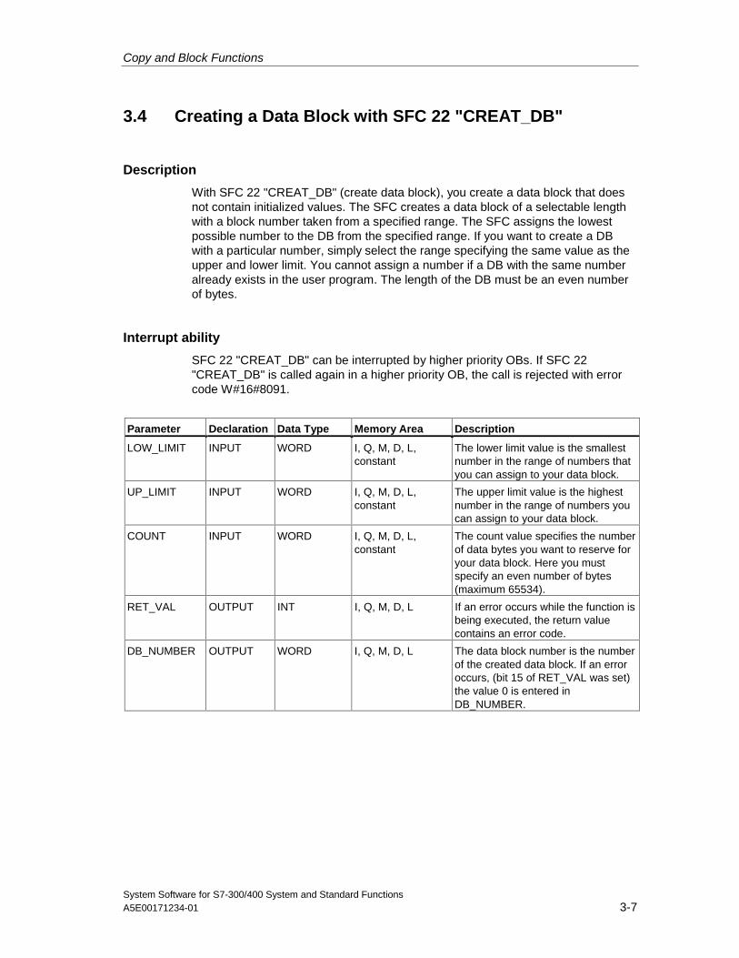
Copy and Block Functions
System Software for S7-300/400 System and Standard FunctionsA5E00171234-01 3-7
3.4 Creating a Data Block with SFC 22 "CREAT_DB"
Description
With SFC 22 "CREAT_DB" (create data block), you create a data block that doesnot contain initialized values. The SFC creates a data block of a selectable lengthwith a block number taken from a specified range. The SFC assigns the lowestpossible number to the DB from the specified range. If you want to create a DBwith a particular number, simply select the range specifying the same value as theupper and lower limit. You cannot assign a number if a DB with the same numberalready exists in the user program. The length of the DB must be an even numberof bytes.
Interrupt ability
SFC 22 "CREAT_DB" can be interrupted by higher priority OBs. If SFC 22"CREAT_DB" is called again in a higher priority OB, the call is rejected with errorcode W#16#8091.
Parameter Declaration Data Type Memory Area Description
LOW_LIMIT INPUT WORD I, Q, M, D, L,constant
The lower limit value is the smallestnumber in the range of numbers thatyou can assign to your data block.
UP_LIMIT INPUT WORD I, Q, M, D, L,constant
The upper limit value is the highestnumber in the range of numbers youcan assign to your data block.
COUNT INPUT WORD I, Q, M, D, L,constant
The count value specifies the numberof data bytes you want to reserve foryour data block. Here you mustspecify an even number of bytes(maximum 65534).
RET_VAL OUTPUT INT I, Q, M, D, L If an error occurs while the function isbeing executed, the return valuecontains an error code.
DB_NUMBER OUTPUT WORD I, Q, M, D, L The data block number is the numberof the created data block. If an erroroccurs, (bit 15 of RET_VAL was set)the value 0 is entered inDB_NUMBER.
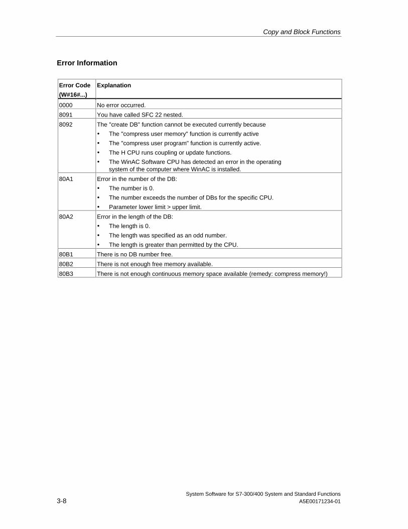
Copy and Block Functions
System Software for S7-300/400 System and Standard Functions3-8 A5E00171234-01
Error Information
Error Code
(W#16#...)
Explanation
0000 No error occurred.
8091 You have called SFC 22 nested.
8092 The "create DB" function cannot be executed currently because
• The "compress user memory" function is currently active
• The "compress user program" function is currently active.
• The H CPU runs coupling or update functions.
• The WinAC Software CPU has detected an error in the operatingsystem of the computer where WinAC is installed.
80A1 Error in the number of the DB:
• The number is 0.
• The number exceeds the number of DBs for the specific CPU.
• Parameter lower limit > upper limit.
80A2 Error in the length of the DB:
• The length is 0.
• The length was specified as an odd number.
• The length is greater than permitted by the CPU.
80B1 There is no DB number free.
80B2 There is not enough free memory available.
80B3 There is not enough continuous memory space available (remedy: compress memory!)
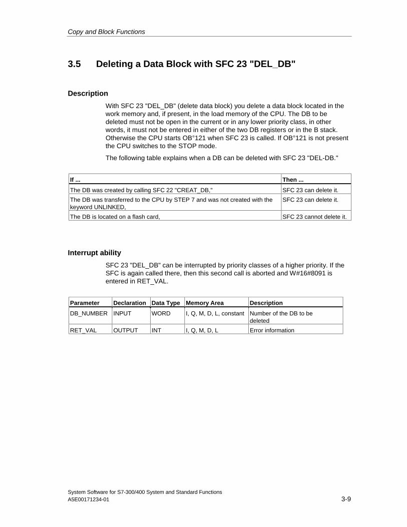
Copy and Block Functions
System Software for S7-300/400 System and Standard FunctionsA5E00171234-01 3-9
3.5 Deleting a Data Block with SFC 23 "DEL_DB"
Description
With SFC 23 "DEL_DB" (delete data block) you delete a data block located in thework memory and, if present, in the load memory of the CPU. The DB to bedeleted must not be open in the current or in any lower priority class, in otherwords, it must not be entered in either of the two DB registers or in the B stack.Otherwise the CPU starts OB°121 when SFC 23 is called. If OB°121 is not presentthe CPU switches to the STOP mode.
The following table explains when a DB can be deleted with SFC 23 "DEL-DB."
If ... Then ...
The DB was created by calling SFC 22 "CREAT_DB," SFC 23 can delete it.
The DB was transferred to the CPU by STEP 7 and was not created with thekeyword UNLINKED,
SFC 23 can delete it.
The DB is located on a flash card, SFC 23 cannot delete it.
Interrupt ability
SFC 23 "DEL_DB" can be interrupted by priority classes of a higher priority. If theSFC is again called there, then this second call is aborted and W#16#8091 isentered in RET_VAL.
Parameter Declaration Data Type Memory Area Description
DB_NUMBER INPUT WORD I, Q, M, D, L, constant Number of the DB to bedeleted
RET_VAL OUTPUT INT I, Q, M, D, L Error information
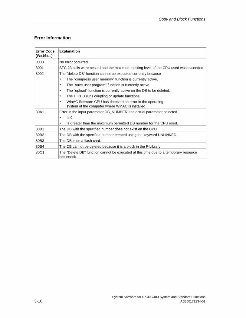
Copy and Block Functions
System Software for S7-300/400 System and Standard Functions3-10 A5E00171234-01
Error Information
Error Code(W#16#...)
Explanation
0000 No error occurred.
8091 SFC 23 calls were nested and the maximum nesting level of the CPU used was exceeded.
8092 The "delete DB" function cannot be executed currently because
• The "compress user memory" function is currently active.
• The "save user program" function is currently active.
• The "upload" function is currently active on the DB to be deleted.
• The H CPU runs coupling or update functions.
• WinAC Software CPU has detected an error in the operatingsystem of the computer where WinAC is installed
80A1 Error in the input parameter DB_NUMBER: the actual parameter selected
• Is 0.
• Is greater than the maximum permitted DB number for the CPU used.
80B1 The DB with the specified number does not exist on the CPU.
80B2 The DB with the specified number created using the keyword UNLINKED.
80B3 The DB is on a flash card.
80B4 The DB cannot be deleted because it is a block in the F-Library
80C1 The "Delete DB" function cannot be executed at this time due to a temporary resourcebottleneck.
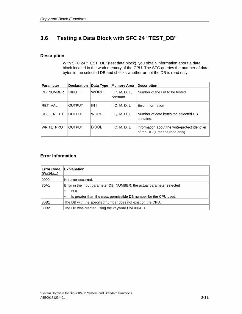
Copy and Block Functions
System Software for S7-300/400 System and Standard FunctionsA5E00171234-01 3-11
3.6 Testing a Data Block with SFC 24 "TEST_DB"
Description
With SFC 24 "TEST_DB" (test data block), you obtain information about a datablock located in the work memory of the CPU. The SFC queries the number of databytes in the selected DB and checks whether or not the DB is read only.
Parameter Declaration Data Type Memory Area Description
DB_NUMBER INPUT WORD I, Q, M, D, L,constant
Number of the DB to be tested
RET_VAL OUTPUT INT I, Q, M, D, L Error information
DB_LENGTH OUTPUT WORD I, Q, M, D, L Number of data bytes the selected DBcontains.
WRITE_PROT OUTPUT BOOL I, Q, M, D, L Information about the write-protect identifierof the DB (1 means read only).
Error Information
Error Code(W#16#...)
Explanation
0000 No error occurred.
80A1 Error in the input parameter DB_NUMBER: the actual parameter selected
• Is 0
• Is greater than the max. permissible DB number for the CPU used.
80B1 The DB with the specified number does not exist on the CPU.
80B2 The DB was created using the keyword UNLINKED.
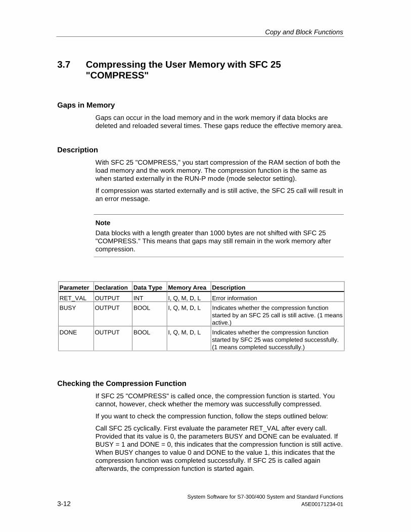
Copy and Block Functions
System Software for S7-300/400 System and Standard Functions3-12 A5E00171234-01
3.7 Compressing the User Memory with SFC 25"COMPRESS"
Gaps in Memory
Gaps can occur in the load memory and in the work memory if data blocks aredeleted and reloaded several times. These gaps reduce the effective memory area.
Description
With SFC 25 "COMPRESS," you start compression of the RAM section of both theload memory and the work memory. The compression function is the same aswhen started externally in the RUN-P mode (mode selector setting).
If compression was started externally and is still active, the SFC 25 call will result inan error message.
Note
Data blocks with a length greater than 1000 bytes are not shifted with SFC 25"COMPRESS." This means that gaps may still remain in the work memory aftercompression.
Parameter Declaration Data Type Memory Area Description
RET_VAL OUTPUT INT I, Q, M, D, L Error information
BUSY OUTPUT BOOL I, Q, M, D, L Indicates whether the compression functionstarted by an SFC 25 call is still active. (1 meansactive.)
DONE OUTPUT BOOL I, Q, M, D, L Indicates whether the compression functionstarted by SFC 25 was completed successfully.(1 means completed successfully.)
Checking the Compression Function
If SFC 25 "COMPRESS" is called once, the compression function is started. Youcannot, however, check whether the memory was successfully compressed.
If you want to check the compression function, follow the steps outlined below:
Call SFC 25 cyclically. First evaluate the parameter RET_VAL after every call.Provided that its value is 0, the parameters BUSY and DONE can be evaluated. IfBUSY = 1 and DONE = 0, this indicates that the compression function is still active.When BUSY changes to value 0 and DONE to the value 1, this indicates that thecompression function was completed successfully. If SFC 25 is called againafterwards, the compression function is started again.
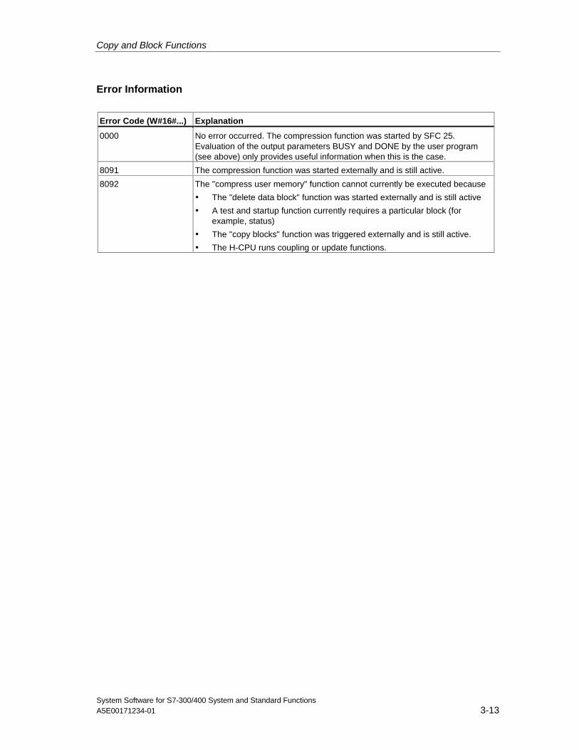
Copy and Block Functions
System Software for S7-300/400 System and Standard FunctionsA5E00171234-01 3-13
Error Information
Error Code (W#16#...) Explanation
0000 No error occurred. The compression function was started by SFC 25.Evaluation of the output parameters BUSY and DONE by the user program(see above) only provides useful information when this is the case.
8091 The compression function was started externally and is still active.
8092 The "compress user memory" function cannot currently be executed because
• The "delete data block" function was started externally and is still active
• A test and startup function currently requires a particular block (forexample, status)
• The "copy blocks" function was triggered externally and is still active.
• The H-CPU runs coupling or update functions.
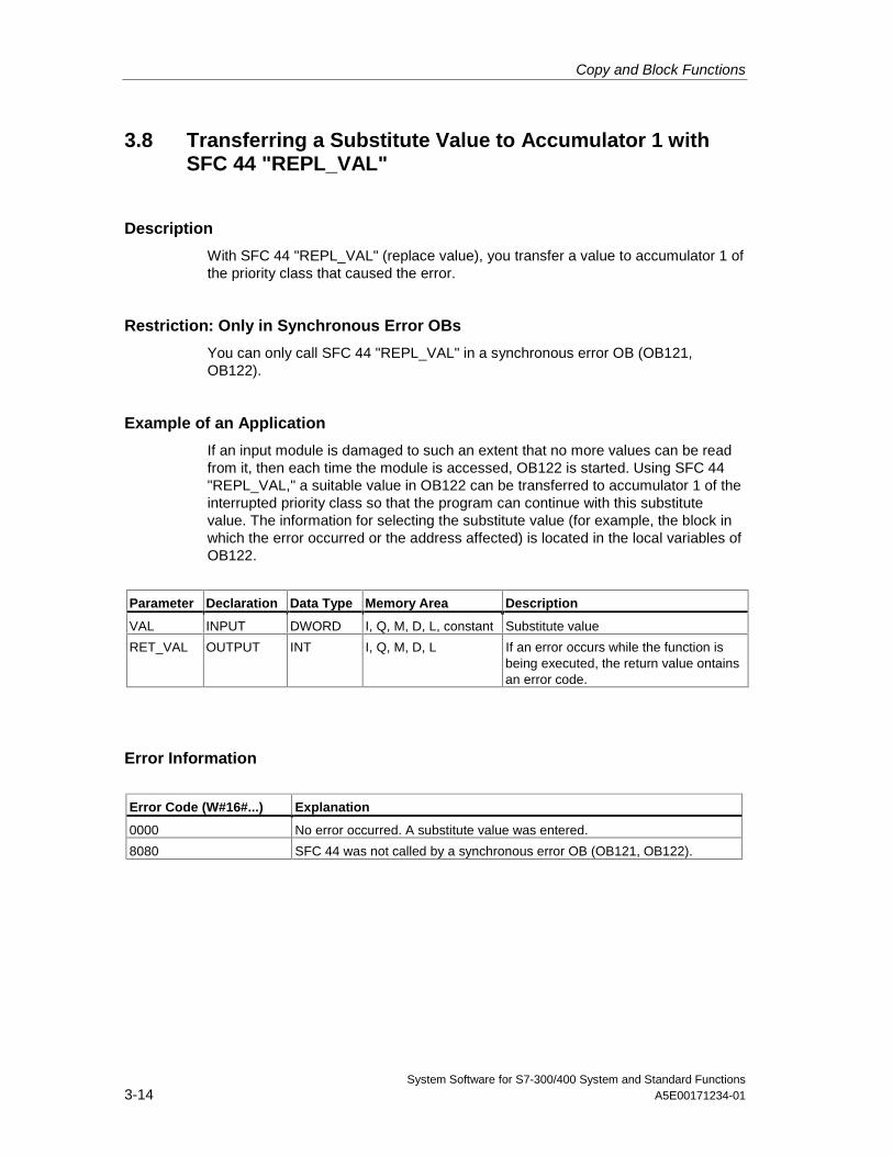
Copy and Block Functions
System Software for S7-300/400 System and Standard Functions3-14 A5E00171234-01
3.8 Transferring a Substitute Value to Accumulator 1 withSFC 44 "REPL_VAL"
Description
With SFC 44 "REPL_VAL" (replace value), you transfer a value to accumulator 1 ofthe priority class that caused the error.
Restriction: Only in Synchronous Error OBs
You can only call SFC 44 "REPL_VAL" in a synchronous error OB (OB121,OB122).
Example of an Application
If an input module is damaged to such an extent that no more values can be readfrom it, then each time the module is accessed, OB122 is started. Using SFC 44"REPL_VAL," a suitable value in OB122 can be transferred to accumulator 1 of theinterrupted priority class so that the program can continue with this substitutevalue. The information for selecting the substitute value (for example, the block inwhich the error occurred or the address affected) is located in the local variables ofOB122.
Parameter Declaration Data Type Memory Area Description
VAL INPUT DWORD I, Q, M, D, L, constant Substitute value
RET_VAL OUTPUT INT I, Q, M, D, L If an error occurs while the function isbeing executed, the return value ontainsan error code.
Error Information
Error Code (W#16#...) Explanation
0000 No error occurred. A substitute value was entered.
8080 SFC 44 was not called by a synchronous error OB (OB121, OB122).
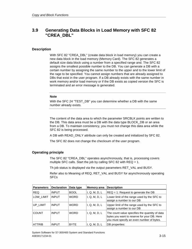
Copy and Block Functions
System Software for S7-300/400 System and Standard FunctionsA5E00171234-01 3-15
3.9 Generating Data Blocks in Load Memory with SFC 82"CREA_DBL"
Description
With SFC 82 "CREA_DBL" (create data block in load memory) you can create anew data block in the load memory (Memory Card). The SFC 82 generates adefault size data block using a number from a specified range and. The SFC 82assigns the smallest possible number to the DB. You can generate a DB with acertain number by assigning the same number to the upper and to the lower limit ofthe rage to be specified. You cannot assign numbers that are already assigned toDBs that exist in the user program. If a DB already exists with the same number inwork memory and/or load memory or if the DB exists as copied version the SFC isterminated and an error message is generated.
Note
With the SFC 24 "TEST_DB" you can determine whether a DB with the samenumber already exists.
The content of the data area to which the parameter SRCBLK points are written tothe DB. This data area must be a DB with the data type BLOCK_DB or an areafrom a DB. To maintain consistency, you must not change this data area while theSFC 82 is being processed.
A DB with READ_ONLY attribute can only be created and initialized by SFC 82.
The SFC 82 does not change the checksum of the user program.
Operating principle
The SFC 82 "CREA_DBL" operates asynchronously, that is, processing coversmultiple SFC calls. Start the job by calling SFC 82 with REQ = 1.
Th job status is displayed via the output parameters RET_VAL and BUSY.
Refer also to Meaning of REQ, RET_VAL and BUSY for asynchronously operatingSFCs
Parameters Declaration Data type Memory area Description
REQ INPUT BOOL I, Q, M, D, L REQ = 1: Request to generate the DB
LOW_LIMIT INPUT WORD I, Q, M, D, L Lower limit of the range used by the SFC toassign a number to our DB
UP_LIMIT INPUT WORD I, Q, M, D, L Upper limit of the range used by the SFC toassign a number to our DB
COUNT INPUT WORD I, Q, M, D, L The count value specifies the quantity of databytes you want to reserve for your DB. Hereyou must specify an even number of bytes.
ATTRIB INPUT BYTE I, Q, M, D, L DB properties:
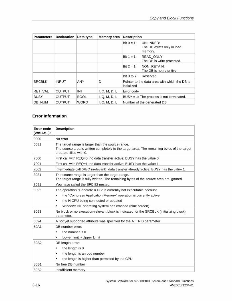
Copy and Block Functions
System Software for S7-300/400 System and Standard Functions3-16 A5E00171234-01
Parameters Declaration Data type Memory area Description
Bit 0 = 1: UNLINKED:The DB exists only in loadmemory.
Bit 1 = 1: READ_ONLY:The DB is write protected.
Bit 2 = 1: NON_RETAIN:The DB is not retentive.
Bit 3 to 7: Reserved
SRCBLK INPUT ANY D Pointer to the data area with which the DB isinitialized
RET_VAL OUTPUT INT I, Q, M, D, L Error code
BUSY OUTPUT BOOL I, Q, M, D, L BUSY = 1: The process is not terminated.
DB_NUM OUTPUT WORD I, Q, M, D, L Number of the generated DB
Error Information
Error code(W#16#...):
Description
0000 No error
0081 The target range is larger than the source range.The source area is written completely to the target area. The remaining bytes of the targetarea are filled with 0.
7000 First call with REQ=0: no data transfer active; BUSY has the value 0.
7001 First call with REQ=1: no data transfer active; BUSY has the value 1.
7002 Intermediate call (REQ irrelevant): data transfer already active; BUSY has the value 1.
8081 The source range is larger than the target range.The target range is fully written. The remaining bytes of the source area are ignored.
8091 You have called the SFC 82 nested.
8092 The operation "Generate a DB" is currently not executable because
• the "Compress Application Memory" operation is currently active
• the H CPU being connected or updated
• Windows NT operating system has crashed (blue screen)
8093 No block or no execution-relevant block is indicated for the SRCBLK (initializing block)parameter.
8094 A not yet supported attribute was specified for the ATTRIB parameter
80A1 DB number error:
• the number is 0
• Lower limit > Upper Limit
80A2 DB length error:
• the length is 0
• the length is an odd number
• the length is higher than permitted by the CPU
80B1 No free DB number
80B2 Insufficient memory
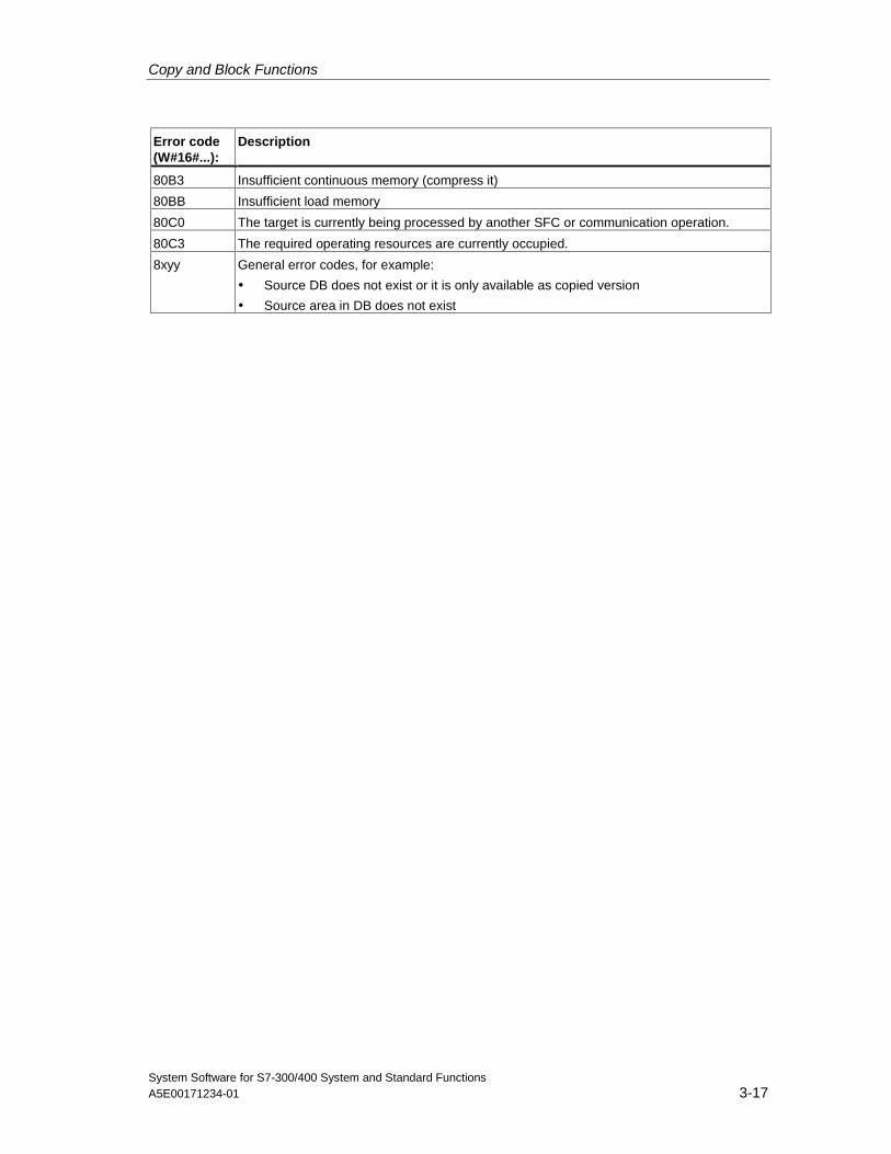
Copy and Block Functions
System Software for S7-300/400 System and Standard FunctionsA5E00171234-01 3-17
Error code(W#16#...):
Description
80B3 Insufficient continuous memory (compress it)
80BB Insufficient load memory
80C0 The target is currently being processed by another SFC or communication operation.
80C3 The required operating resources are currently occupied.
8xyy General error codes, for example:
• Source DB does not exist or it is only available as copied version
• Source area in DB does not exist
Copy and Block Functions
System Software for S7-300/400 System and Standard Functions3-18 A5E00171234-01
3.10 Reading from a Data Block In Load Memory with SFC 83"READ_DBL"
Description
Use SFC 83 "READ_DBL" (read data block in load memory) to fetch a DB of thedata type BLOCK_DB or an area from a DB in load memory (Memory Card) to thedata area of a target DB. The target DB must be relevant for execution (keywordUNLINKED = 0). The source area to be read does not need to be relevant toexecution (keyword UNLINKED = 1). The content of the load memory is notchanged during the read process.
To maintain consistency, you must not change the target area while the SFC83 isbeing processed.
The following restrictions apply to the parameters SRCBLK and DSTBLK:
• For an ANY pointer of the type BOOLEAN the length must be divisible by 8.
• For an ANY pointer of the type BOOLEAN the length must be divisible by 1.
If required, you can determine the length of the source area with SFC24"TEST_DB".
Note
The SFC 83 is processed asynchronously. Therefore, it is not suitable for frequentreading of variables from load memory.
Note
Once started, a job is always completed, even if the same resource is requestedby a job with higher priority. If error code 80C3 is displayed at the high-priority runlevel, it does not make sense to restart the high-priority job right away. Instead, youshould wait until the blocking job is completed.
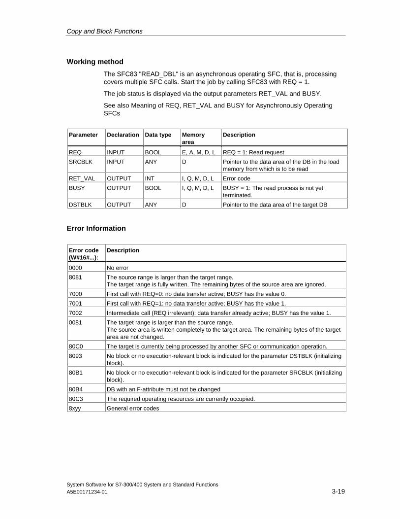
Copy and Block Functions
System Software for S7-300/400 System and Standard FunctionsA5E00171234-01 3-19
Working method
The SFC83 "READ_DBL" is an asynchronous operating SFC, that is, processingcovers multiple SFC calls. Start the job by calling SFC83 with REQ = 1.
The job status is displayed via the output parameters RET_VAL and BUSY.
See also Meaning of REQ, RET_VAL and BUSY for Asynchronously OperatingSFCs
Parameter Declaration Data type Memoryarea
Description
REQ INPUT BOOL E, A, M, D, L REQ = 1: Read request
SRCBLK INPUT ANY D Pointer to the data area of the DB in the loadmemory from which is to be read
RET_VAL OUTPUT INT I, Q, M, D, L Error code
BUSY OUTPUT BOOL I, Q, M, D, L BUSY = 1: The read process is not yetterminated.
DSTBLK OUTPUT ANY D Pointer to the data area of the target DB
Error Information
Error code(W#16#...):
Description
0000 No error
8081 The source range is larger than the target range.The target range is fully written. The remaining bytes of the source area are ignored.
7000 First call with REQ=0: no data transfer active; BUSY has the value 0.
7001 First call with REQ=1: no data transfer active; BUSY has the value 1.
7002 Intermediate call (REQ irrelevant): data transfer already active; BUSY has the value 1.
0081 The target range is larger than the source range.The source area is written completely to the target area. The remaining bytes of the targetarea are not changed.
80C0 The target is currently being processed by another SFC or communication operation.
8093 No block or no execution-relevant block is indicated for the parameter DSTBLK (initializingblock).
80B1 No block or no execution-relevant block is indicated for the parameter SRCBLK (initializingblock).
80B4 DB with an F-attribute must not be changed
80C3 The required operating resources are currently occupied.
8xyy General error codes
Copy and Block Functions
System Software for S7-300/400 System and Standard Functions3-20 A5E00171234-01
3.11 Writing a Data Block in Load Memory with SFC 84"WRIT_DBL"
Description
With the SFC84 "WRIT_DBL" (write data block in load memory) you can write asource DB in a DB of the data type BLOCK DB or into an area of a DB in loadmemory (Memory Card). The DB in load memory to which the parameter DSTBLKrefers can be relevant or not relevant for processing. The source area to which theparameter SRCBLK refers can be of data type BLOCK_DB or a DB(-content) in thework memory. The source DB to which the parameter SRCBLK refers musttherefore be process relevant (keyword UNLINKED = 0). The source DB can alsobe generate with SFC22 "CREAT_DB".
To maintain consistency, you must not change the source area while the SFC 83 isbeing processed.
The following restrictions apply to the parameters SRCBLK and DSTBLK:
• For an ANY pointer of the type BOOLEAN the length must be divisible by 8.
• For an ANY pointer of the type STRING the length must be equal to 1.
If required, you can determine the length of the target DB with SFC24 "TEST_DB".
SFC82 does not change the checksum of the user program if you describe a DBthat was generated via SFC. When writing a loaded DB the first entry in this DBchanges the checksum of the user program.
Note
SFC 84 is processed asynchronously and is therefore not suitable for writingvariables to the load memory frequently. Please note that write access to a MicroMemory Card is limited for technological reasons.
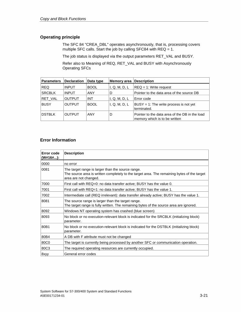
Copy and Block Functions
System Software for S7-300/400 System and Standard FunctionsA5E00171234-01 3-21
Operating principle
The SFC 84 "CREA_DBL" operates asynchronously, that is, processing coversmultiple SFC calls. Start the job by calling SFC84 with REQ = 1.
The job status is displayed via the output parameters RET_VAL and BUSY.
Refer also to Meaning of REQ, RET_VAL and BUSY with AsynchronouslyOperating SFCs
Parameters Declaration Data type Memory area Description
REQ INPUT BOOL I, Q, M, D, L REQ = 1: Write request
SRCBLK INPUT ANY D Pointer to the data area of the source DB
RET_VAL OUTPUT INT I, Q, M, D, L Error code
BUSY OUTPUT BOOL I, Q, M, D, L BUSY = 1: The write process is not yetterminated.
DSTBLK OUTPUT ANY D Pointer to the data area of the DB in the loadmemory which is to be written
Error Information
Error code(W#16#...):
Description
0000 no error
0081 The target range is larger than the source range.The source area is written completely to the target area. The remaining bytes of the targetarea are not changed.
7000 First call with REQ=0: no data transfer active; BUSY has the value 0.
7001 First call with REQ=1: no data transfer active; BUSY has the value 1.
7002 Intermediate call (REQ irrelevant): data transfer already active; BUSY has the value 1.
8081 The source range is larger than the target range.The target range is fully written. The remaining bytes of the source area are ignored.
8092 Windows NT operating system has crashed (blue screen)
8093 No block or no execution-relevant block is indicated for the SRCBLK (initializing block)parameter.
80B1 No block or no execution-relevant block is indicated for the DSTBLK (initializing block)parameter.
80B4 A DB with F attribute must not be changed
80C0 The target is currently being processed by another SFC or communication operation.
80C3 The required operating resources are currently occupied.
8xyy General error codes

Copy and Block Functions
System Software for S7-300/400 System and Standard Functions3-22 A5E00171234-01
System Software for S7-300/400 System and Standard FunctionsA5E00171234-01 4-1
4 SFCs for Controlling Program Execution
4.1 Re-triggering Cycle Time Monitoring with SFC 43"RE_TRIGR"
Description
With SFC 43 "RE_TRIGR" (re-trigger watchdog), you can re-trigger the cycle timemonitoring.
Parameters
SFC 43 "RE_TRIGR" has no parameters.
Error Information
SFC 43 "RE_TRIGR" does not provide any error information.
4.2 Changing the CPU to STOP with SFC 46 "STP"
Description
With SFC 46 "STP" (stop), you change the CPU to the STOP mode.
Parameters
SFC 46 "STP" does not have any parameters.
Error Information
SFC 46 "STP" does not provide any error information.
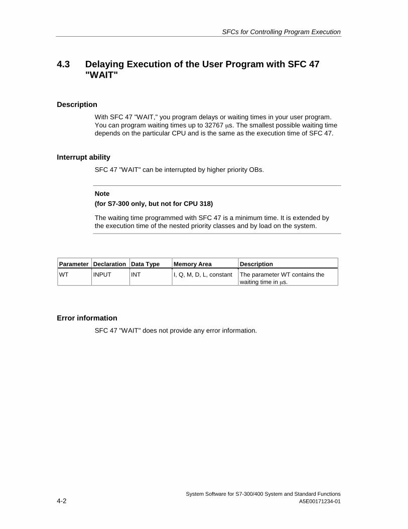
SFCs for Controlling Program Execution
System Software for S7-300/400 System and Standard Functions4-2 A5E00171234-01
4.3 Delaying Execution of the User Program with SFC 47"WAIT"
Description
With SFC 47 "WAIT," you program delays or waiting times in your user program.You can program waiting times up to 32767 µs. The smallest possible waiting timedepends on the particular CPU and is the same as the execution time of SFC 47.
Interrupt ability
SFC 47 "WAIT" can be interrupted by higher priority OBs.
Note
(for S7-300 only, but not for CPU 318)
The waiting time programmed with SFC 47 is a minimum time. It is extended bythe execution time of the nested priority classes and by load on the system.
Parameter Declaration Data Type Memory Area Description
WT INPUT INT I, Q, M, D, L, constant The parameter WT contains thewaiting time in µs.
Error information
SFC 47 "WAIT" does not provide any error information.
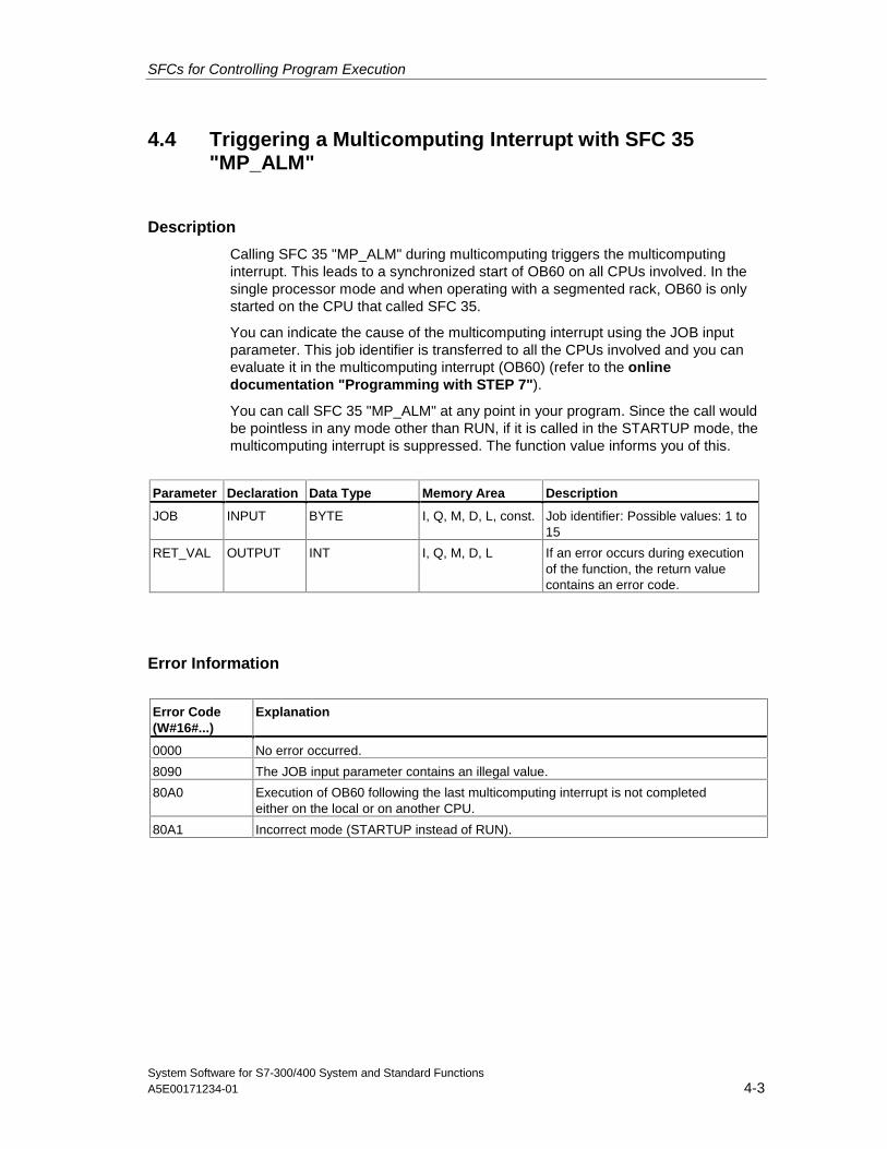
SFCs for Controlling Program Execution
System Software for S7-300/400 System and Standard FunctionsA5E00171234-01 4-3
4.4 Triggering a Multicomputing Interrupt with SFC 35"MP_ALM"
Description
Calling SFC 35 "MP_ALM" during multicomputing triggers the multicomputinginterrupt. This leads to a synchronized start of OB60 on all CPUs involved. In thesingle processor mode and when operating with a segmented rack, OB60 is onlystarted on the CPU that called SFC 35.
You can indicate the cause of the multicomputing interrupt using the JOB inputparameter. This job identifier is transferred to all the CPUs involved and you canevaluate it in the multicomputing interrupt (OB60) (refer to the onlinedocumentation "Programming with STEP 7").
You can call SFC 35 "MP_ALM" at any point in your program. Since the call wouldbe pointless in any mode other than RUN, if it is called in the STARTUP mode, themulticomputing interrupt is suppressed. The function value informs you of this.
Parameter Declaration Data Type Memory Area Description
JOB INPUT BYTE I, Q, M, D, L, const. Job identifier: Possible values: 1 to15
RET_VAL OUTPUT INT I, Q, M, D, L If an error occurs during executionof the function, the return valuecontains an error code.
Error Information
Error Code(W#16#...)
Explanation
0000 No error occurred.
8090 The JOB input parameter contains an illegal value.
80A0 Execution of OB60 following the last multicomputing interrupt is not completedeither on the local or on another CPU.
80A1 Incorrect mode (STARTUP instead of RUN).
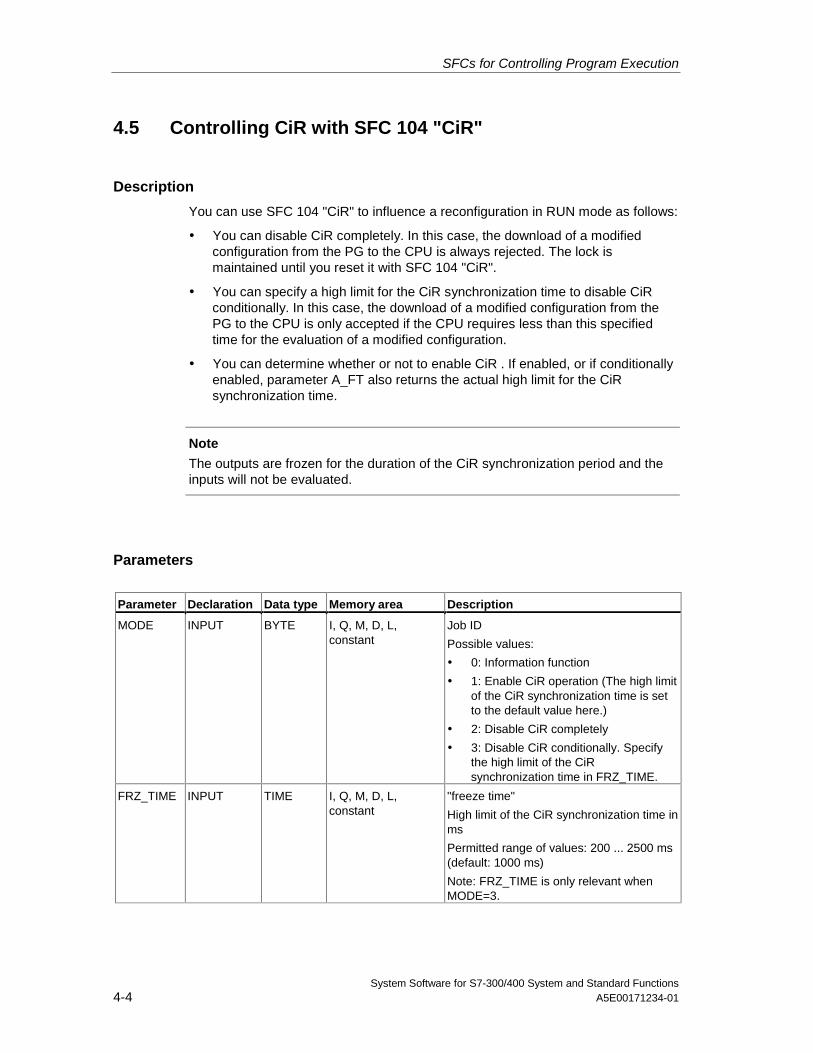
SFCs for Controlling Program Execution
System Software for S7-300/400 System and Standard Functions4-4 A5E00171234-01
4.5 Controlling CiR with SFC 104 "CiR"
Description
You can use SFC 104 "CiR" to influence a reconfiguration in RUN mode as follows:
• You can disable CiR completely. In this case, the download of a modifiedconfiguration from the PG to the CPU is always rejected. The lock ismaintained until you reset it with SFC 104 "CiR".
• You can specify a high limit for the CiR synchronization time to disable CiRconditionally. In this case, the download of a modified configuration from thePG to the CPU is only accepted if the CPU requires less than this specifiedtime for the evaluation of a modified configuration.
• You can determine whether or not to enable CiR . If enabled, or if conditionallyenabled, parameter A_FT also returns the actual high limit for the CiRsynchronization time.
Note
The outputs are frozen for the duration of the CiR synchronization period and theinputs will not be evaluated.
Parameters
Parameter Declaration Data type Memory area Description
MODE INPUT BYTE I, Q, M, D, L,constant
Job ID
Possible values:
• 0: Information function
• 1: Enable CiR operation (The high limitof the CiR synchronization time is setto the default value here.)
• 2: Disable CiR completely
• 3: Disable CiR conditionally. Specifythe high limit of the CiRsynchronization time in FRZ_TIME.
FRZ_TIME INPUT TIME I, Q, M, D, L,constant
"freeze time"
High limit of the CiR synchronization time inms
Permitted range of values: 200 ... 2500 ms(default: 1000 ms)
Note: FRZ_TIME is only relevant whenMODE=3.
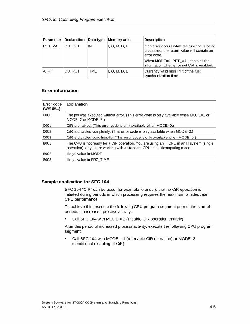
SFCs for Controlling Program Execution
System Software for S7-300/400 System and Standard FunctionsA5E00171234-01 4-5
Parameter Declaration Data type Memory area Description
RET_VAL OUTPUT INT I, Q, M, D, L If an error occurs while the function is beingprocessed, the return value will contain anerror code.
When MODE=0, RET_VAL contains theinformation whether or not CiR is enabled.
A_FT OUTPUT TIME I, Q, M, D, L Currently valid high limit of the CiRsynchronization time
Error information
Error code(W#16#...)
Explanation
0000 The job was executed without error. (This error code is only available when MODE=1 orMODE=2 or MODE=3.)
0001 CiR is enabled. (This error code is only available when MODE=0.)
0002 CiR is disabled completely. (This error code is only available when MODE=0.)
0003 CiR is disabled conditionally. (This error code is only available when MODE=0.)
8001 The CPU is not ready for a CiR operation. You are using an H CPU in an H system (singleoperation), or you are working with a standard CPU in multicomputing mode.
8002 Illegal value in MODE
8003 Illegal value in FRZ_TIME
Sample application for SFC 104
SFC 104 "CIR" can be used, for example to ensure that no CiR operation isinitiated during periods in which processing requires the maximum or adequateCPU performance.
To achieve this, execute the following CPU program segment prior to the start ofperiods of increased process activity:
• Call SFC 104 with MODE = 2 (Disable CiR operation entirely)
After this period of increased process activity, execute the following CPU programsegment:
• Call SFC 104 with MODE = 1 (re-enable CiR operation) or MODE=3(conditional disabling of CiR)

SFCs for Controlling Program Execution
System Software for S7-300/400 System and Standard Functions4-6 A5E00171234-01
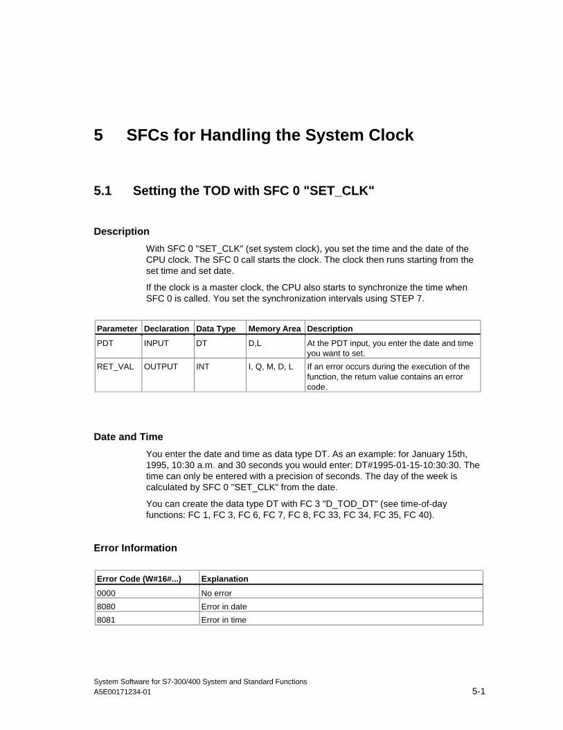
System Software for S7-300/400 System and Standard FunctionsA5E00171234-01 5-1
5 SFCs for Handling the System Clock
5.1 Setting the TOD with SFC 0 "SET_CLK"
Description
With SFC 0 "SET_CLK" (set system clock), you set the time and the date of theCPU clock. The SFC 0 call starts the clock. The clock then runs starting from theset time and set date.
If the clock is a master clock, the CPU also starts to synchronize the time whenSFC 0 is called. You set the synchronization intervals using STEP 7.
Parameter Declaration Data Type Memory Area Description
PDT INPUT DT D,L At the PDT input, you enter the date and timeyou want to set.
RET_VAL OUTPUT INT I, Q, M, D, L If an error occurs during the execution of thefunction, the return value contains an errorcode.
Date and Time
You enter the date and time as data type DT. As an example: for January 15th,1995, 10:30 a.m. and 30 seconds you would enter: DT#1995-01-15-10:30:30. Thetime can only be entered with a precision of seconds. The day of the week iscalculated by SFC 0 "SET_CLK" from the date.
You can create the data type DT with FC 3 "D_TOD_DT" (see time-of-dayfunctions: FC 1, FC 3, FC 6, FC 7, FC 8, FC 33, FC 34, FC 35, FC 40).
Error Information
Error Code (W#16#...) Explanation
0000 No error
8080 Error in date
8081 Error in time
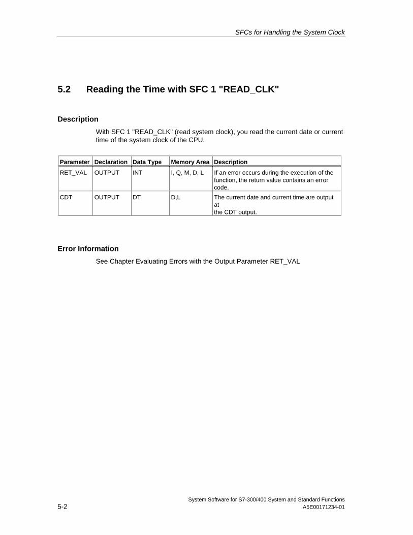
SFCs for Handling the System Clock
System Software for S7-300/400 System and Standard Functions5-2 A5E00171234-01
5.2 Reading the Time with SFC 1 "READ_CLK"
Description
With SFC 1 "READ_CLK" (read system clock), you read the current date or currenttime of the system clock of the CPU.
Parameter Declaration Data Type Memory Area Description
RET_VAL OUTPUT INT I, Q, M, D, L If an error occurs during the execution of thefunction, the return value contains an errorcode.
CDT OUTPUT DT D,L The current date and current time are outputatthe CDT output.
Error Information
See Chapter Evaluating Errors with the Output Parameter RET_VAL
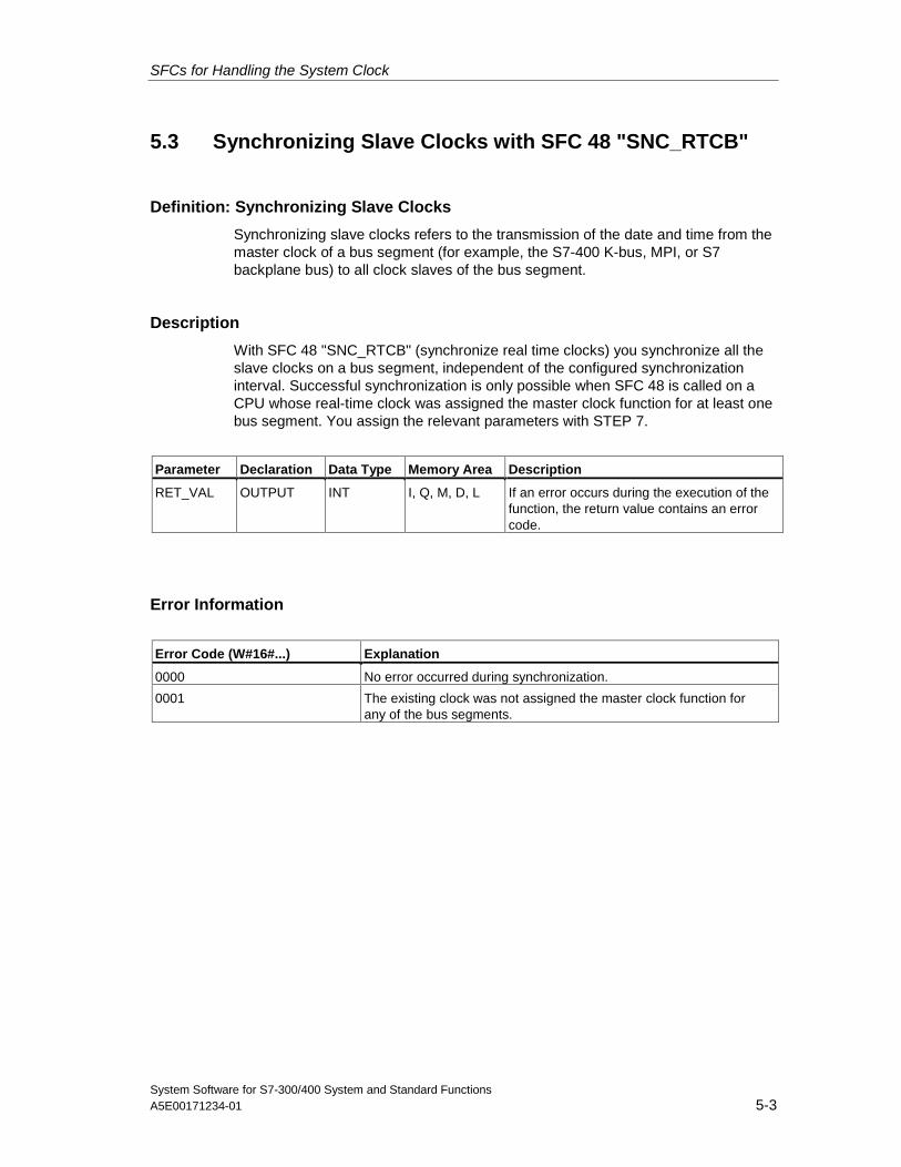
SFCs for Handling the System Clock
System Software for S7-300/400 System and Standard FunctionsA5E00171234-01 5-3
5.3 Synchronizing Slave Clocks with SFC 48 "SNC_RTCB"
Definition: Synchronizing Slave Clocks
Synchronizing slave clocks refers to the transmission of the date and time from themaster clock of a bus segment (for example, the S7-400 K-bus, MPI, or S7backplane bus) to all clock slaves of the bus segment.
Description
With SFC 48 "SNC_RTCB" (synchronize real time clocks) you synchronize all theslave clocks on a bus segment, independent of the configured synchronizationinterval. Successful synchronization is only possible when SFC 48 is called on aCPU whose real-time clock was assigned the master clock function for at least onebus segment. You assign the relevant parameters with STEP 7.
Parameter Declaration Data Type Memory Area Description
RET_VAL OUTPUT INT I, Q, M, D, L If an error occurs during the execution of thefunction, the return value contains an errorcode.
Error Information
Error Code (W#16#...) Explanation
0000 No error occurred during synchronization.
0001 The existing clock was not assigned the master clock function forany of the bus segments.
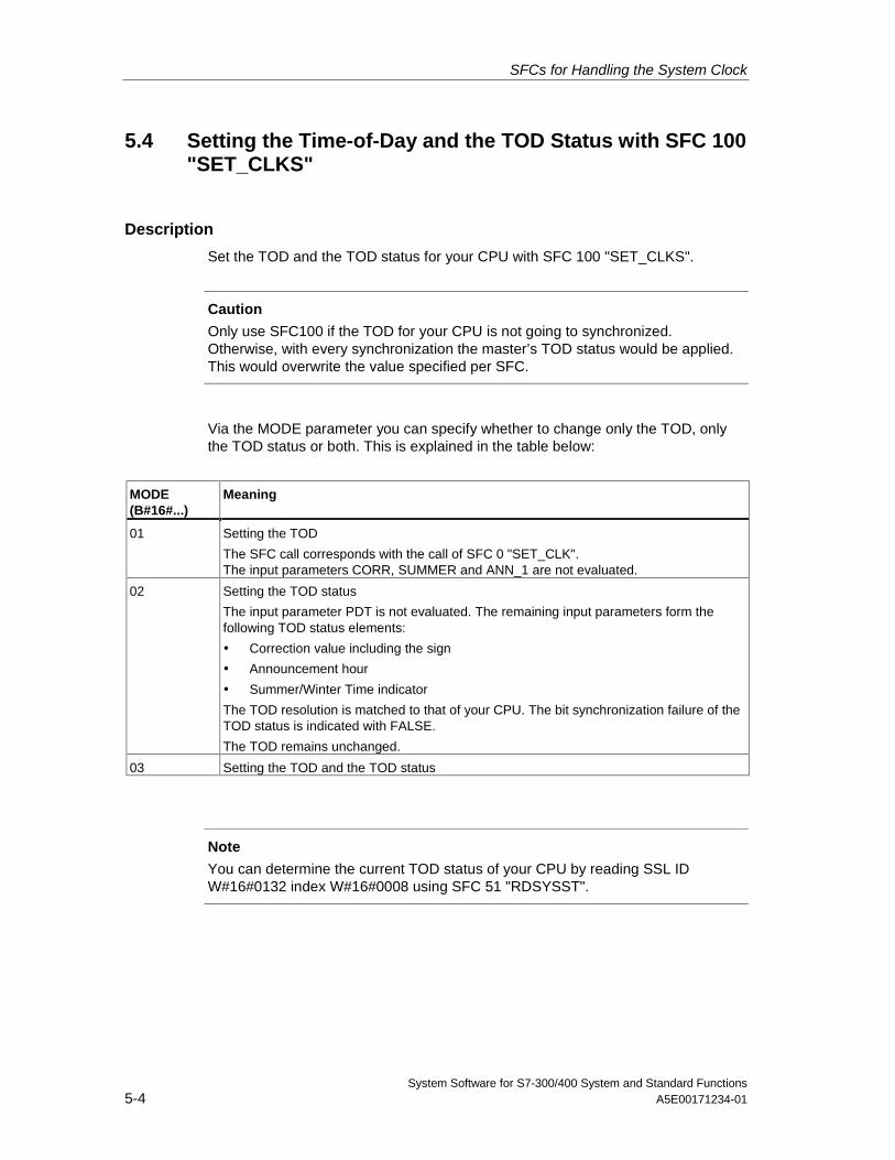
SFCs for Handling the System Clock
System Software for S7-300/400 System and Standard Functions5-4 A5E00171234-01
5.4 Setting the Time-of-Day and the TOD Status with SFC 100"SET_CLKS"
Description
Set the TOD and the TOD status for your CPU with SFC 100 "SET_CLKS".
Caution
Only use SFC100 if the TOD for your CPU is not going to synchronized.Otherwise, with every synchronization the master’s TOD status would be applied.This would overwrite the value specified per SFC.
Via the MODE parameter you can specify whether to change only the TOD, onlythe TOD status or both. This is explained in the table below:
MODE(B#16#...)
Meaning
01 Setting the TOD
The SFC call corresponds with the call of SFC 0 "SET_CLK".The input parameters CORR, SUMMER and ANN_1 are not evaluated.
02 Setting the TOD status
The input parameter PDT is not evaluated. The remaining input parameters form thefollowing TOD status elements:
• Correction value including the sign
• Announcement hour
• Summer/Winter Time indicator
The TOD resolution is matched to that of your CPU. The bit synchronization failure of theTOD status is indicated with FALSE.
The TOD remains unchanged.
03 Setting the TOD and the TOD status
Note
You can determine the current TOD status of your CPU by reading SSL IDW#16#0132 index W#16#0008 using SFC 51 "RDSYSST".
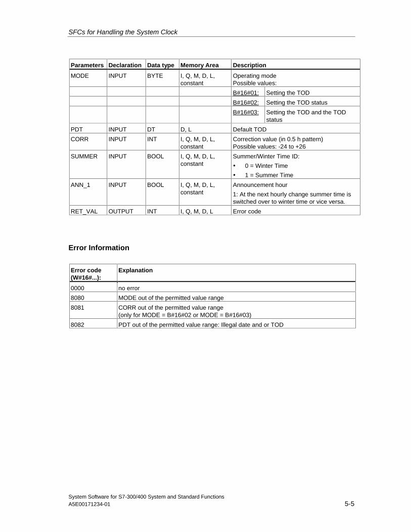
SFCs for Handling the System Clock
System Software for S7-300/400 System and Standard FunctionsA5E00171234-01 5-5
Parameters Declaration Data type Memory Area Description
MODE INPUT BYTE I, Q, M, D, L,constant
Operating modePossible values:
B#16#01: Setting the TOD
B#16#02: Setting the TOD status
B#16#03: Setting the TOD and the TODstatus
PDT INPUT DT D, L Default TOD
CORR INPUT INT I, Q, M, D, L,constant
Correction value (in 0.5 h pattern)Possible values: -24 to +26
SUMMER INPUT BOOL I, Q, M, D, L,constant
Summer/Winter Time ID:
• 0 = Winter Time
• 1 = Summer Time
ANN_1 INPUT BOOL I, Q, M, D, L,constant
Announcement hour
1: At the next hourly change summer time isswitched over to winter time or vice versa.
RET_VAL OUTPUT INT I, Q, M, D, L Error code
Error Information
Error code(W#16#...):
Explanation
0000 no error
8080 MODE out of the permitted value range
8081 CORR out of the permitted value range(only for MODE = B#16#02 or MODE = B#16#03)
8082 PDT out of the permitted value range: Illegal date and or TOD

SFCs for Handling the System Clock
System Software for S7-300/400 System and Standard Functions5-6 A5E00171234-01
System Software for S7-300/400 System and Standard FunctionsA5E00171234-01 6-1
6 SFCs for Handling Run-Time Meters
6.1 Runtime Meters
Introduction
The CPUs have a number of runtime meters (refer to the data sheets of yourCPUs).
• If your CPU is equipped with 16-bit runtime meters, you can set, start, stop orread them with the SFCs 2, 3 and 4.
• If your CPU is equipped with 32-bit runtime meters, you can set, start, stop orread them with SFC 101 "RTM".
Note
SFCs 2, 3 and 4 can also be used for 32-bit runtime meters. In this case however,the runtime meters operate in a 16-bit mode (Range of values: 0 to 32767 hours).See also: Data Record of Partial List Extract with SSL ID W#16#0132 IndexW#16#000B.
Application
You can use a runtime meter for a variety of applications:
• For measuring the runtime of the CPU
• For measuring the runtime of controlled equipment or connected devices.
Characteristics of the Runtime Meter
When it is started, the runtime meter begins to count starting at the last recordedvalue. If you want it to start at a different initial value, you must explicitly specifythis value (SFC 2 or SFC 101 with MODE=4).. If the CPU changes to the STOPmode, or you stop the runtime meter, the CPU records the current value of theruntime meter. When a warm restart or a cold restart of the CPU is executed, theruntime meter must be restarted (SFC 3 or SFC 101 with MODE=1).
Range of Values
• CPU with 16-bit runtime meters: 0 to 32 767 hours
• CPU with 32-bit runtime meters: 0 to (2E31) -1 hours = 2.147.483.647 hours
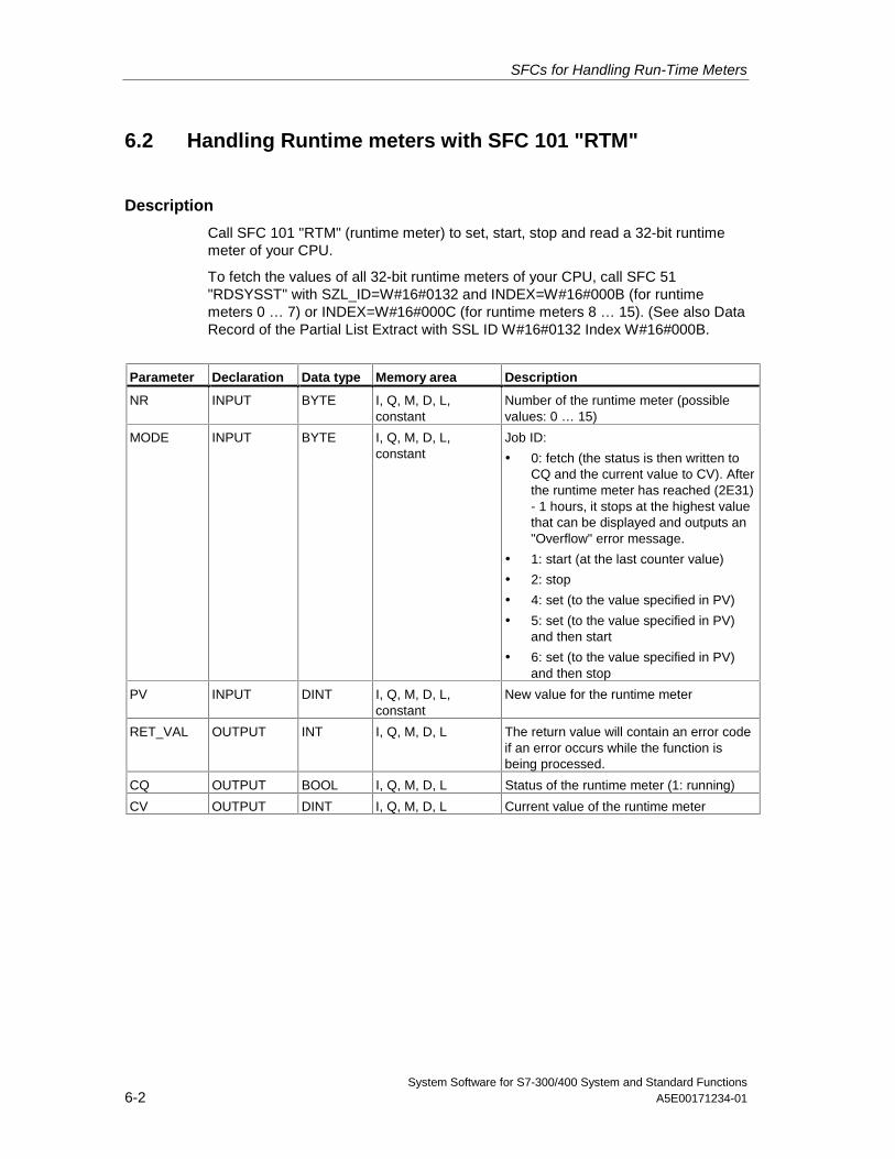
SFCs for Handling Run-Time Meters
System Software for S7-300/400 System and Standard Functions6-2 A5E00171234-01
6.2 Handling Runtime meters with SFC 101 "RTM"
Description
Call SFC 101 "RTM" (runtime meter) to set, start, stop and read a 32-bit runtimemeter of your CPU.
To fetch the values of all 32-bit runtime meters of your CPU, call SFC 51"RDSYSST" with SZL_ID=W#16#0132 and INDEX=W#16#000B (for runtimemeters 0 … 7) or INDEX=W#16#000C (for runtime meters 8 … 15). (See also DataRecord of the Partial List Extract with SSL ID W#16#0132 Index W#16#000B.
Parameter Declaration Data type Memory area Description
NR INPUT BYTE I, Q, M, D, L,constant
Number of the runtime meter (possiblevalues: 0 … 15)
MODE INPUT BYTE I, Q, M, D, L,constant
Job ID:
• 0: fetch (the status is then written toCQ and the current value to CV). Afterthe runtime meter has reached (2E31)- 1 hours, it stops at the highest valuethat can be displayed and outputs an"Overflow" error message.
• 1: start (at the last counter value)
• 2: stop
• 4: set (to the value specified in PV)
• 5: set (to the value specified in PV)and then start
• 6: set (to the value specified in PV)and then stop
PV INPUT DINT I, Q, M, D, L,constant
New value for the runtime meter
RET_VAL OUTPUT INT I, Q, M, D, L The return value will contain an error codeif an error occurs while the function isbeing processed.
CQ OUTPUT BOOL I, Q, M, D, L Status of the runtime meter (1: running)
CV OUTPUT DINT I, Q, M, D, L Current value of the runtime meter
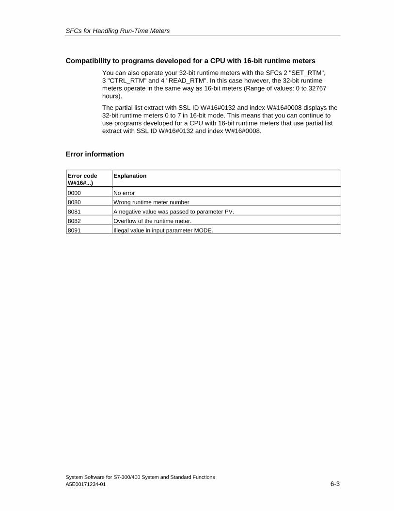
SFCs for Handling Run-Time Meters
System Software for S7-300/400 System and Standard FunctionsA5E00171234-01 6-3
Compatibility to programs developed for a CPU with 16-bit runtime meters
You can also operate your 32-bit runtime meters with the SFCs 2 "SET_RTM",3 "CTRL_RTM" and 4 "READ_RTM". In this case however, the 32-bit runtimemeters operate in the same way as 16-bit meters (Range of values: 0 to 32767hours).
The partial list extract with SSL ID W#16#0132 and index W#16#0008 displays the32-bit runtime meters 0 to 7 in 16-bit mode. This means that you can continue touse programs developed for a CPU with 16-bit runtime meters that use partial listextract with SSL ID W#16#0132 and index W#16#0008.
Error information
Error codeW#16#...)
Explanation
0000 No error
8080 Wrong runtime meter number
8081 A negative value was passed to parameter PV.
8082 Overflow of the runtime meter.
8091 Illegal value in input parameter MODE.
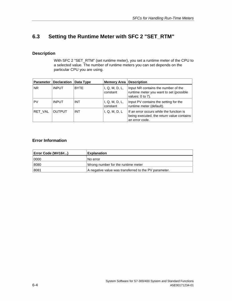
SFCs for Handling Run-Time Meters
System Software for S7-300/400 System and Standard Functions6-4 A5E00171234-01
6.3 Setting the Runtime Meter with SFC 2 "SET_RTM"
Description
With SFC 2 "SET_RTM" (set runtime meter), you set a runtime meter of the CPU toa selected value. The number of runtime meters you can set depends on theparticular CPU you are using.
Parameter Declaration Data Type Memory Area Description
NR INPUT BYTE I, Q, M, D, L,constant
Input NR contains the number of theruntime meter you want to set (possiblevalues: 0 to 7).
PV INPUT INT I, Q, M, D, L,constant
Input PV contains the setting for theruntime meter (default).
RET_VAL OUTPUT INT I, Q, M, D, L If an error occurs while the function isbeing executed, the return value containsan error code.
Error Information
Error Code (W#16#...) Explanation
0000 No error
8080 Wrong number for the runtime meter
8081 A negative value was transferred to the PV parameter.
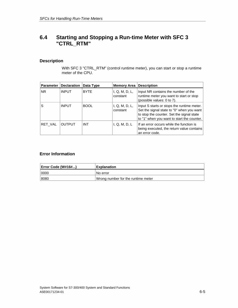
SFCs for Handling Run-Time Meters
System Software for S7-300/400 System and Standard FunctionsA5E00171234-01 6-5
6.4 Starting and Stopping a Run-time Meter with SFC 3"CTRL_RTM"
Description
With SFC 3 "CTRL_RTM" (control runtime meter), you can start or stop a runtimemeter of the CPU.
Parameter Declaration Data Type Memory Area Description
NR INPUT BYTE I, Q, M, D, L,constant
Input NR contains the number of theruntime meter you want to start or stop(possible values: 0 to 7).
S INPUT BOOL I, Q, M, D, L,constant
Input S starts or stops the runtime meter.Set the signal state to "0" when you wantto stop the counter. Set the signal stateto "1" when you want to start the counter.
RET_VAL OUTPUT INT I, Q, M, D, L If an error occurs while the function isbeing executed, the return value containsan error code.
Error Information
Error Code (W#16#...) Explanation
0000 No error
8080 Wrong number for the runtime meter
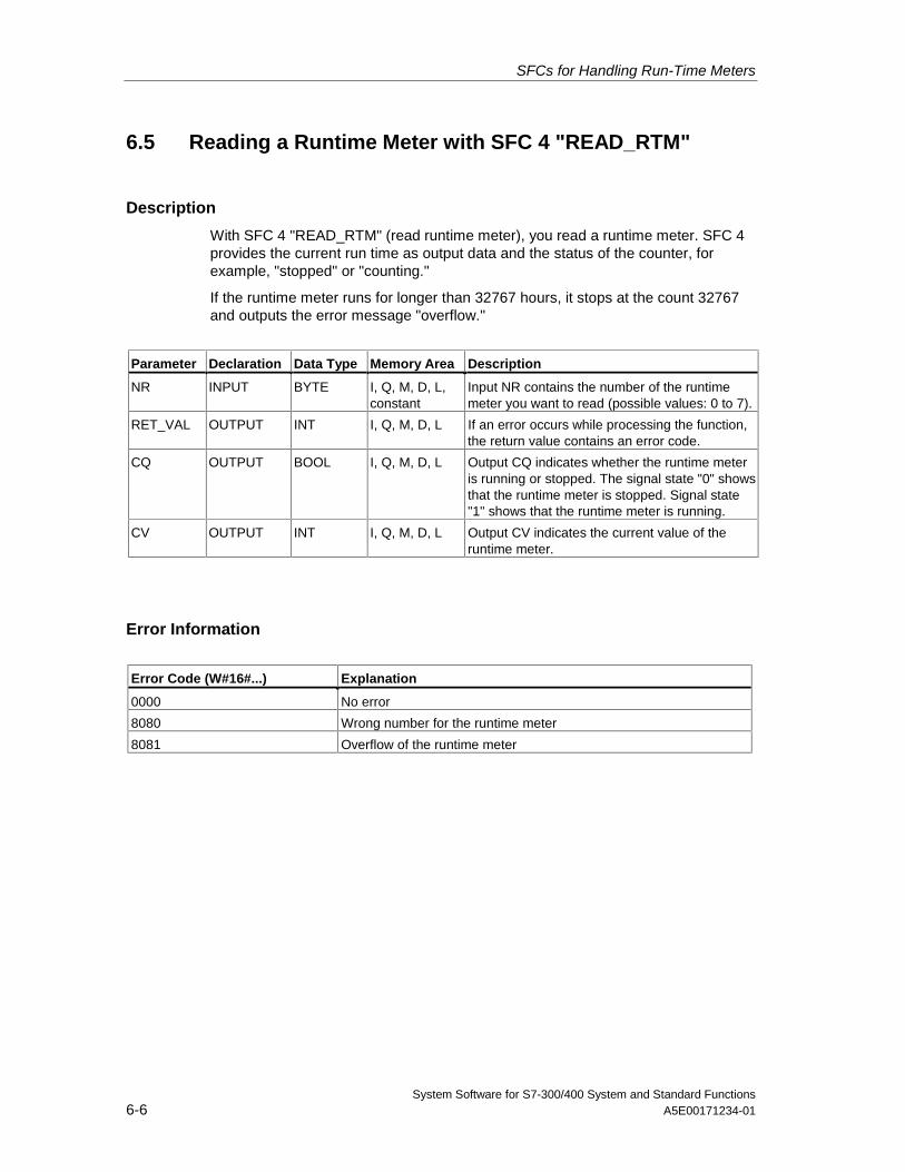
SFCs for Handling Run-Time Meters
System Software for S7-300/400 System and Standard Functions6-6 A5E00171234-01
6.5 Reading a Runtime Meter with SFC 4 "READ_RTM"
Description
With SFC 4 "READ_RTM" (read runtime meter), you read a runtime meter. SFC 4provides the current run time as output data and the status of the counter, forexample, "stopped" or "counting."
If the runtime meter runs for longer than 32767 hours, it stops at the count 32767and outputs the error message "overflow."
Parameter Declaration Data Type Memory Area Description
NR INPUT BYTE I, Q, M, D, L,constant
Input NR contains the number of the runtimemeter you want to read (possible values: 0 to 7).
RET_VAL OUTPUT INT I, Q, M, D, L If an error occurs while processing the function,the return value contains an error code.
CQ OUTPUT BOOL I, Q, M, D, L Output CQ indicates whether the runtime meteris running or stopped. The signal state "0" showsthat the runtime meter is stopped. Signal state"1" shows that the runtime meter is running.
CV OUTPUT INT I, Q, M, D, L Output CV indicates the current value of theruntime meter.
Error Information
Error Code (W#16#...) Explanation
0000 No error
8080 Wrong number for the runtime meter
8081 Overflow of the runtime meter
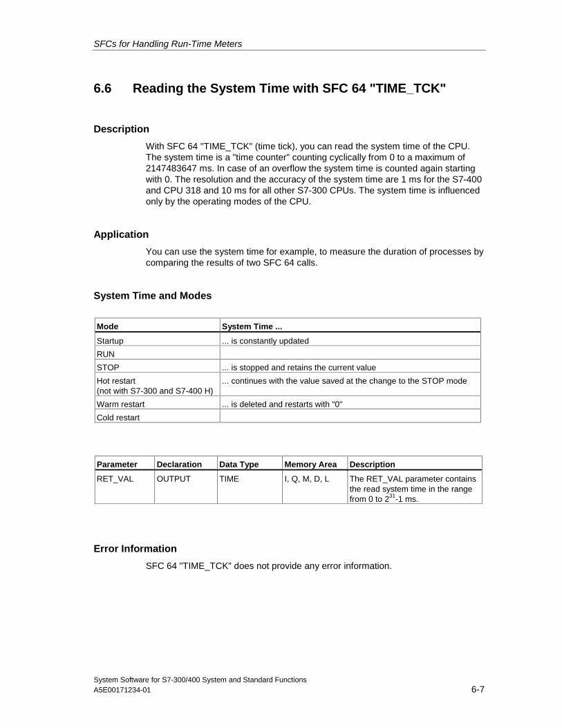
SFCs for Handling Run-Time Meters
System Software for S7-300/400 System and Standard FunctionsA5E00171234-01 6-7
6.6 Reading the System Time with SFC 64 "TIME_TCK"
Description
With SFC 64 "TIME_TCK" (time tick), you can read the system time of the CPU.The system time is a "time counter" counting cyclically from 0 to a maximum of2147483647 ms. In case of an overflow the system time is counted again startingwith 0. The resolution and the accuracy of the system time are 1 ms for the S7-400and CPU 318 and 10 ms for all other S7-300 CPUs. The system time is influencedonly by the operating modes of the CPU.
Application
You can use the system time for example, to measure the duration of processes bycomparing the results of two SFC 64 calls.
System Time and Modes
Mode System Time ...
Startup ... is constantly updated
RUN
STOP ... is stopped and retains the current value
Hot restart(not with S7-300 and S7-400 H)
... continues with the value saved at the change to the STOP mode
Warm restart ... is deleted and restarts with "0"
Cold restart
Parameter Declaration Data Type Memory Area Description
RET_VAL OUTPUT TIME I, Q, M, D, L The RET_VAL parameter containsthe read system time in the rangefrom 0 to 231-1 ms.
Error Information
SFC 64 "TIME_TCK" does not provide any error information.

SFCs for Handling Run-Time Meters
System Software for S7-300/400 System and Standard Functions6-8 A5E00171234-01
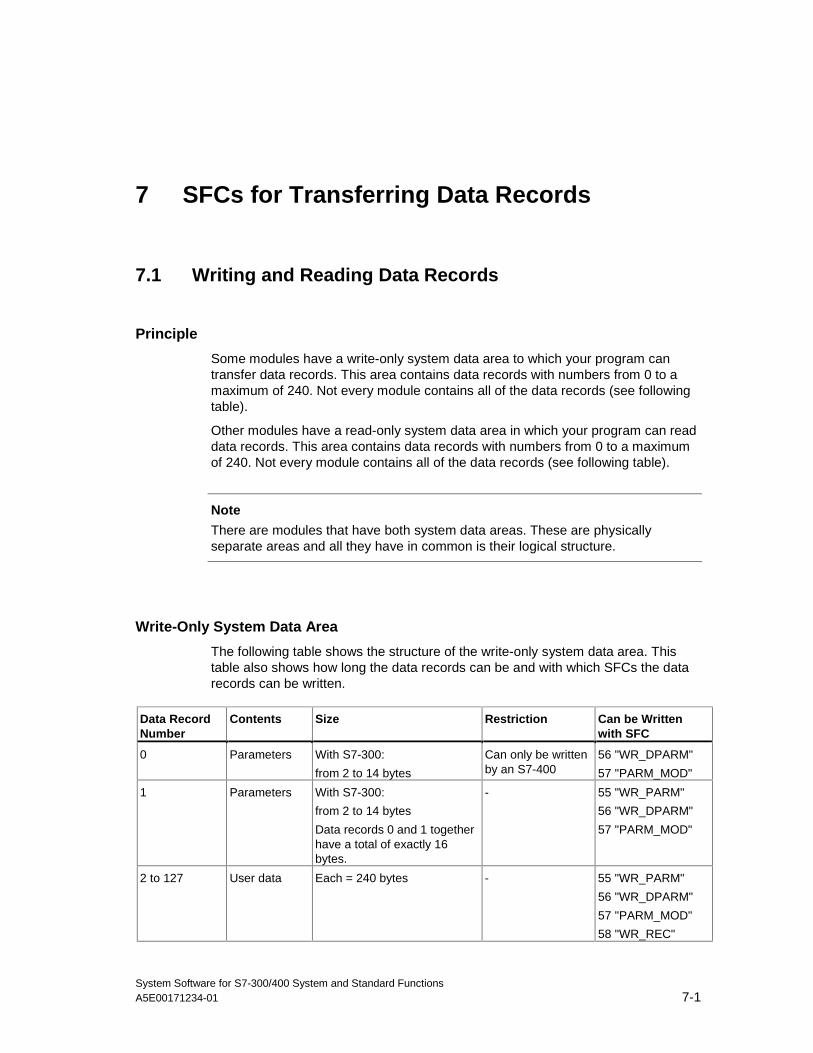
System Software for S7-300/400 System and Standard FunctionsA5E00171234-01 7-1
7 SFCs for Transferring Data Records
7.1 Writing and Reading Data Records
Principle
Some modules have a write-only system data area to which your program cantransfer data records. This area contains data records with numbers from 0 to amaximum of 240. Not every module contains all of the data records (see followingtable).
Other modules have a read-only system data area in which your program can readdata records. This area contains data records with numbers from 0 to a maximumof 240. Not every module contains all of the data records (see following table).
Note
There are modules that have both system data areas. These are physicallyseparate areas and all they have in common is their logical structure.
Write-Only System Data Area
The following table shows the structure of the write-only system data area. Thistable also shows how long the data records can be and with which SFCs the datarecords can be written.
Data RecordNumber
Contents Size Restriction Can be Writtenwith SFC
0 Parameters With S7-300:
from 2 to 14 bytes
Can only be writtenby an S7-400
56 "WR_DPARM"
57 "PARM_MOD"
1 Parameters With S7-300:
from 2 to 14 bytes
Data records 0 and 1 togetherhave a total of exactly 16bytes.
- 55 "WR_PARM"
56 "WR_DPARM"
57 "PARM_MOD"
2 to 127 User data Each = 240 bytes - 55 "WR_PARM"
56 "WR_DPARM"
57 "PARM_MOD"
58 "WR_REC"
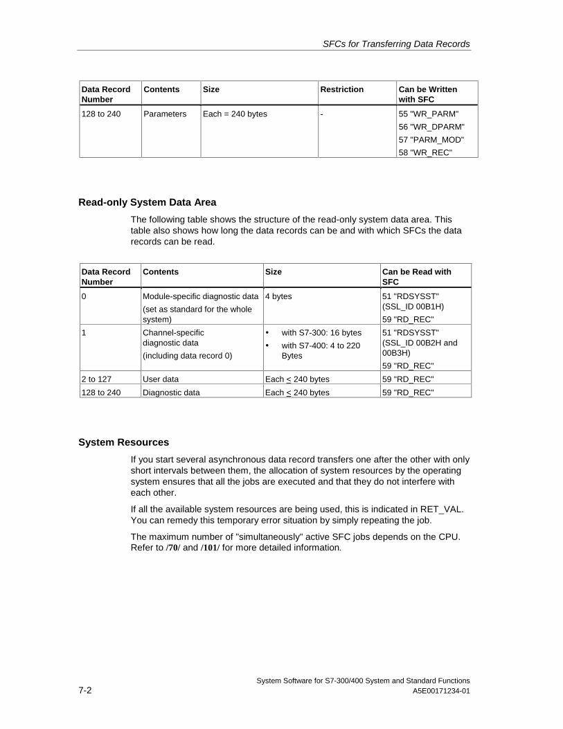
SFCs for Transferring Data Records
System Software for S7-300/400 System and Standard Functions7-2 A5E00171234-01
Data RecordNumber
Contents Size Restriction Can be Writtenwith SFC
128 to 240 Parameters Each = 240 bytes - 55 "WR_PARM"
56 "WR_DPARM"
57 "PARM_MOD"
58 "WR_REC"
Read-only System Data Area
The following table shows the structure of the read-only system data area. Thistable also shows how long the data records can be and with which SFCs the datarecords can be read.
Data RecordNumber
Contents Size Can be Read withSFC
0 Module-specific diagnostic data
(set as standard for the wholesystem)
4 bytes 51 "RDSYSST"(SSL_ID 00B1H)
59 "RD_REC"
1 Channel-specificdiagnostic data
(including data record 0)
• with S7-300: 16 bytes
• with S7-400: 4 to 220Bytes
51 "RDSYSST"(SSL_ID 00B2H and00B3H)
59 "RD_REC"
2 to 127 User data Each < 240 bytes 59 "RD_REC"
128 to 240 Diagnostic data Each < 240 bytes 59 "RD_REC"
System Resources
If you start several asynchronous data record transfers one after the other with onlyshort intervals between them, the allocation of system resources by the operatingsystem ensures that all the jobs are executed and that they do not interfere witheach other.
If all the available system resources are being used, this is indicated in RET_VAL.You can remedy this temporary error situation by simply repeating the job.
The maximum number of "simultaneously" active SFC jobs depends on the CPU.Refer to /70/ and /101/ for more detailed information.
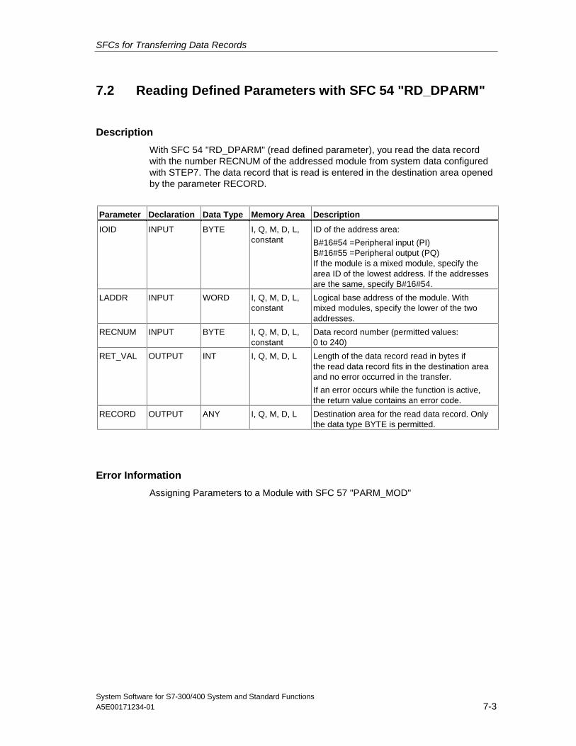
SFCs for Transferring Data Records
System Software for S7-300/400 System and Standard FunctionsA5E00171234-01 7-3
7.2 Reading Defined Parameters with SFC 54 "RD_DPARM"
Description
With SFC 54 "RD_DPARM" (read defined parameter), you read the data recordwith the number RECNUM of the addressed module from system data configuredwith STEP7. The data record that is read is entered in the destination area openedby the parameter RECORD.
Parameter Declaration Data Type Memory Area Description
IOID INPUT BYTE I, Q, M, D, L,constant
ID of the address area:
B#16#54 =Peripheral input (PI)B#16#55 =Peripheral output (PQ)If the module is a mixed module, specify thearea ID of the lowest address. If the addressesare the same, specify B#16#54.
LADDR INPUT WORD I, Q, M, D, L,constant
Logical base address of the module. Withmixed modules, specify the lower of the twoaddresses.
RECNUM INPUT BYTE I, Q, M, D, L,constant
Data record number (permitted values:0 to 240)
RET_VAL OUTPUT INT I, Q, M, D, L Length of the data record read in bytes ifthe read data record fits in the destination areaand no error occurred in the transfer.
If an error occurs while the function is active,the return value contains an error code.
RECORD OUTPUT ANY I, Q, M, D, L Destination area for the read data record. Onlythe data type BYTE is permitted.
Error Information
Assigning Parameters to a Module with SFC 57 "PARM_MOD"
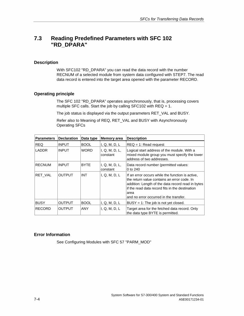
SFCs for Transferring Data Records
System Software for S7-300/400 System and Standard Functions7-4 A5E00171234-01
7.3 Reading Predefined Parameters with SFC 102"RD_DPARA"
Description
With SFC102 "RD_DPARA" you can read the data record with the numberRECNUM of a selected module from system data configured with STEP7. The readdata record is entered into the target area opened with the parameter RECORD.
Operating principle
The SFC 102 "RD_DPARA" operates asynchronously, that is, processing coversmultiple SFC calls. Start the job by calling SFC102 with REQ = 1.
The job status is displayed via the output parameters RET_VAL and BUSY.
Refer also to Meaning of REQ, RET_VAL and BUSY with AsynchronouslyOperating SFCs
Parameters Declaration Data type Memory area Description
REQ INPUT BOOL I, Q, M, D, L REQ = 1: Read request
LADDR INPUT WORD I, Q, M, D, L,constant
Logical start address of the module. With amixed module group you must specify the loweraddress of two addresses.
RECNUM INPUT BYTE I, Q, M, D, L,constant
Data record number (permitted values:0 to 240
RET_VAL OUTPUT INT I, Q, M, D, L If an error occurs while the function is active,the return value contains an error code. Inaddition: Length of the data record read in bytesif the read data record fits in the destinationareaand no error occurred in the transfer.
BUSY OUTPUT BOOL I, Q, M, D, L BUSY = 1: The job is not yet closed.
RECORD OUTPUT ANY I, Q, M, D, L Target area for the fetched data record. Onlythe data type BYTE is permitted.
Error Information
See Configuring Modules with SFC 57 "PARM_MOD"
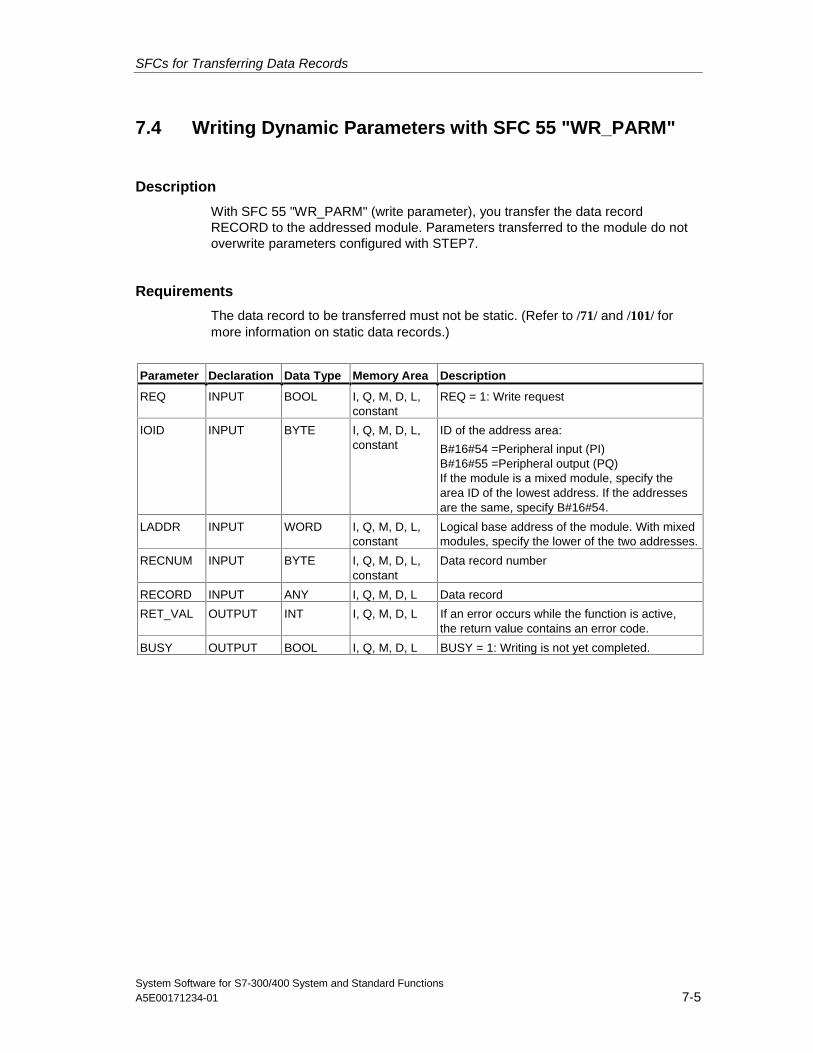
SFCs for Transferring Data Records
System Software for S7-300/400 System and Standard FunctionsA5E00171234-01 7-5
7.4 Writing Dynamic Parameters with SFC 55 "WR_PARM"
Description
With SFC 55 "WR_PARM" (write parameter), you transfer the data recordRECORD to the addressed module. Parameters transferred to the module do notoverwrite parameters configured with STEP7.
Requirements
The data record to be transferred must not be static. (Refer to /71/ and /101/ formore information on static data records.)
Parameter Declaration Data Type Memory Area Description
REQ INPUT BOOL I, Q, M, D, L,constant
REQ = 1: Write request
IOID INPUT BYTE I, Q, M, D, L,constant
ID of the address area:
B#16#54 =Peripheral input (PI)B#16#55 =Peripheral output (PQ)If the module is a mixed module, specify thearea ID of the lowest address. If the addressesare the same, specify B#16#54.
LADDR INPUT WORD I, Q, M, D, L,constant
Logical base address of the module. With mixedmodules, specify the lower of the two addresses.
RECNUM INPUT BYTE I, Q, M, D, L,constant
Data record number
RECORD INPUT ANY I, Q, M, D, L Data record
RET_VAL OUTPUT INT I, Q, M, D, L If an error occurs while the function is active,the return value contains an error code.
BUSY OUTPUT BOOL I, Q, M, D, L BUSY = 1: Writing is not yet completed.
SFCs for Transferring Data Records
System Software for S7-300/400 System and Standard Functions7-6 A5E00171234-01
Input Parameter RECORD
The data to be transferred are read from the parameter RECORD during the firstSFC call. If the transfer of the data record takes longer than the duration of a call,the contents of the parameter RECORD are no longer relevant for the subsequentSFC calls (for the same job).
Error Information
Assigning Parameters to a Module with SFC 57 "PARM_MOD"
Note(S7-400 only)
If the general error W#16#8544 occurs, this only indicates that access to at leastone byte of the I/O memory area containing the data record was denied. The datatransfer was continued.
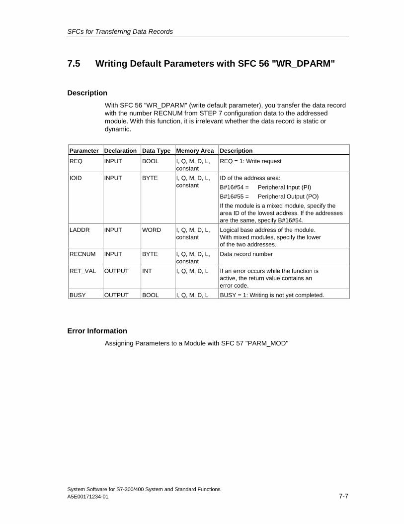
SFCs for Transferring Data Records
System Software for S7-300/400 System and Standard FunctionsA5E00171234-01 7-7
7.5 Writing Default Parameters with SFC 56 "WR_DPARM"
Description
With SFC 56 "WR_DPARM" (write default parameter), you transfer the data recordwith the number RECNUM from STEP 7 configuration data to the addressedmodule. With this function, it is irrelevant whether the data record is static ordynamic.
Parameter Declaration Data Type Memory Area Description
REQ INPUT BOOL I, Q, M, D, L,constant
REQ = 1: Write request
IOID INPUT BYTE I, Q, M, D, L,constant
ID of the address area:
B#16#54 = Peripheral Input (PI)
B#16#55 = Peripheral Output (PO)
If the module is a mixed module, specify thearea ID of the lowest address. If the addressesare the same, specify B#16#54.
LADDR INPUT WORD I, Q, M, D, L,constant
Logical base address of the module.With mixed modules, specify the lowerof the two addresses.
RECNUM INPUT BYTE I, Q, M, D, L,constant
Data record number
RET_VAL OUTPUT INT I, Q, M, D, L If an error occurs while the function isactive, the return value contains anerror code.
BUSY OUTPUT BOOL I, Q, M, D, L BUSY = 1: Writing is not yet completed.
Error Information
Assigning Parameters to a Module with SFC 57 "PARM_MOD"
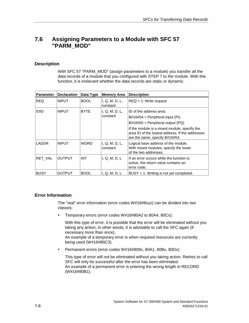
SFCs for Transferring Data Records
System Software for S7-300/400 System and Standard Functions7-8 A5E00171234-01
7.6 Assigning Parameters to a Module with SFC 57"PARM_MOD"
Description
With SFC 57 "PARM_MOD" (assign parameters to a module) you transfer all thedata records of a module that you configured with STEP 7 to the module. With thisfunction, it is irrelevant whether the data records are static or dynamic.
Parameter Declaration Data Type Memory Area Description
REQ INPUT BOOL I, Q, M, D, L,constant
REQ = 1: Write request
IOID INPUT BYTE I, Q, M, D, L,constant
ID of the address area:
B#16#54 = Peripheral input (PI)
B#16#55 = Peripheral output (PQ)
If the module is a mixed module, specify thearea ID of the lowest address. If the addressesare the same, specify B#16#54.
LADDR INPUT WORD I, Q, M, D, L,constant
Logical base address of the module.With mixed modules, specify the lowerof the two addresses.
RET_VAL OUTPUT INT I, Q, M, D, L If an error occurs while the function isactive, the return value contains anerror code.
BUSY OUTPUT BOOL I, Q, M, D, L BUSY = 1: Writing is not yet completed.
Error Information
The "real" error information (error codes W#16#8xyz) can be divided into twoclasses:
• Temporary errors (error codes W#16#80A2 to 80A4, 80Cx):
With this type of error, it is possible that the error will be eliminated without youtaking any action, in other words, it is advisable to call the SFC again (ifnecessary more than once).An example of a temporary error is when required resources are currentlybeing used (W#16#80C3).
• Permanent errors (error codes W#16#809x, 80A1, 80Bx, 80Dx):
This type of error will not be eliminated without you taking action. Retries to callSFC will only be successful after the error has been eliminated.An example of a permanent error is entering the wrong length in RECORD(W#16#80B1).
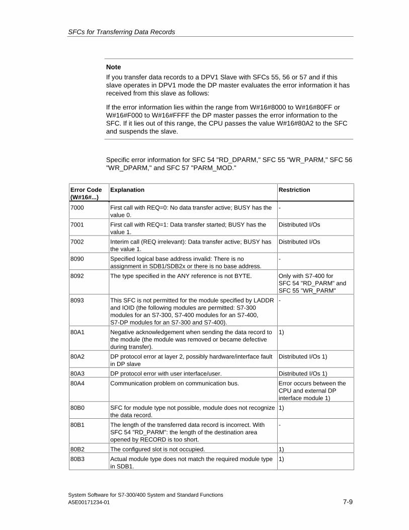
SFCs for Transferring Data Records
System Software for S7-300/400 System and Standard FunctionsA5E00171234-01 7-9
Note
If you transfer data records to a DPV1 Slave with SFCs 55, 56 or 57 and if thisslave operates in DPV1 mode the DP master evaluates the error information it hasreceived from this slave as follows:
If the error information lies within the range from W#16#8000 to W#16#80FF orW#16#F000 to W#16#FFFF the DP master passes the error information to theSFC. If it lies out of this range, the CPU passes the value W#16#80A2 to the SFCand suspends the slave.
Specific error information for SFC 54 "RD_DPARM," SFC 55 "WR_PARM," SFC 56"WR_DPARM," and SFC 57 "PARM_MOD."
Error Code(W#16#...)
Explanation Restriction
7000 First call with REQ=0: No data transfer active; BUSY has thevalue 0.
-
7001 First call with REQ=1: Data transfer started; BUSY has thevalue 1.
Distributed I/Os
7002 Interim call (REQ irrelevant): Data transfer active; BUSY hasthe value 1.
Distributed I/Os
8090 Specified logical base address invalid: There is noassignment in SDB1/SDB2x or there is no base address.
-
8092 The type specified in the ANY reference is not BYTE. Only with S7-400 forSFC 54 "RD_PARM" andSFC 55 "WR_PARM"
8093 This SFC is not permitted for the module specified by LADDRand IOID (the following modules are permitted: S7-300modules for an S7-300, S7-400 modules for an S7-400,S7-DP modules for an S7-300 and S7-400).
-
80A1 Negative acknowledgement when sending the data record tothe module (the module was removed or became defectiveduring transfer).
1)
80A2 DP protocol error at layer 2, possibly hardware/interface faultin DP slave
Distributed I/Os 1)
80A3 DP protocol error with user interface/user. Distributed I/Os 1)
80A4 Communication problem on communication bus. Error occurs between theCPU and external DPinterface module 1)
80B0 SFC for module type not possible, module does not recognizethe data record.
1)
80B1 The length of the transferred data record is incorrect. WithSFC 54 "RD_PARM": the length of the destination areaopened by RECORD is too short.
-
80B2 The configured slot is not occupied. 1)
80B3 Actual module type does not match the required module typein SDB1.
1)

SFCs for Transferring Data Records
System Software for S7-300/400 System and Standard Functions7-10 A5E00171234-01
Error Code(W#16#...)
Explanation Restriction
80C1 The data of the previous write job for the same data record onthe module have not yet been processed by the module.
1)
80C2 The module is currently processing the maximum possiblenumber of jobs for a CPU.
1)
80C3 The required resources (memory, etc.) are currently occupied. 1)
80C4 Internal temporary error. The job could not be processed.
• Repeat the job. If this error occurs frequently check yoursystem for electrical disturbance sources.
1)
80C5 Distributed I/Os not available. Distributed I/Os 1)
80C6 Data record transfer was stopped due to a priority class abort(hot restart or background)
Distributed I/Os 1)
80D0 There is no entry for the module in the corresponding SDB. -
80D1 The data record number is not configured in thecorresponding SDB for the module (data record numbers =241 are rejected by STEP 7).
-
80D2 The module cannot be assigned parameters according to itstype identifier.
-
80D3 The SDB cannot be accessed since it does not exist. -
80D4 SDB structure error: The SDB internal pointer points to avalue outside the SDB.
only with S7-300
80D5 The data record is static. only with SFC 55"WR_PARM"
1) Does not occur in SFC 54 "RD_DPARM"
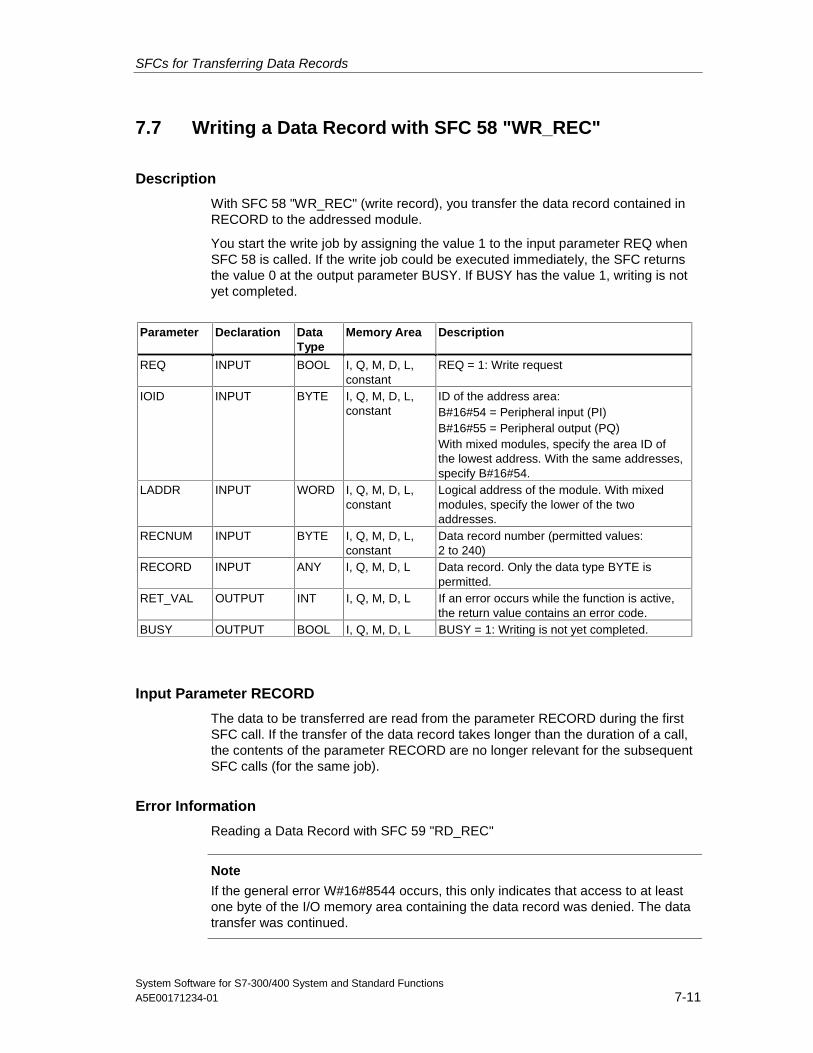
SFCs for Transferring Data Records
System Software for S7-300/400 System and Standard FunctionsA5E00171234-01 7-11
7.7 Writing a Data Record with SFC 58 "WR_REC"
Description
With SFC 58 "WR_REC" (write record), you transfer the data record contained inRECORD to the addressed module.
You start the write job by assigning the value 1 to the input parameter REQ whenSFC 58 is called. If the write job could be executed immediately, the SFC returnsthe value 0 at the output parameter BUSY. If BUSY has the value 1, writing is notyet completed.
Parameter Declaration DataType
Memory Area Description
REQ INPUT BOOL I, Q, M, D, L,constant
REQ = 1: Write request
IOID INPUT BYTE I, Q, M, D, L,constant
ID of the address area:B#16#54 = Peripheral input (PI)B#16#55 = Peripheral output (PQ)With mixed modules, specify the area ID ofthe lowest address. With the same addresses,specify B#16#54.
LADDR INPUT WORD I, Q, M, D, L,constant
Logical address of the module. With mixedmodules, specify the lower of the twoaddresses.
RECNUM INPUT BYTE I, Q, M, D, L,constant
Data record number (permitted values:2 to 240)
RECORD INPUT ANY I, Q, M, D, L Data record. Only the data type BYTE ispermitted.
RET_VAL OUTPUT INT I, Q, M, D, L If an error occurs while the function is active,the return value contains an error code.
BUSY OUTPUT BOOL I, Q, M, D, L BUSY = 1: Writing is not yet completed.
Input Parameter RECORD
The data to be transferred are read from the parameter RECORD during the firstSFC call. If the transfer of the data record takes longer than the duration of a call,the contents of the parameter RECORD are no longer relevant for the subsequentSFC calls (for the same job).
Error Information
Reading a Data Record with SFC 59 "RD_REC"
Note
If the general error W#16#8544 occurs, this only indicates that access to at leastone byte of the I/O memory area containing the data record was denied. The datatransfer was continued.
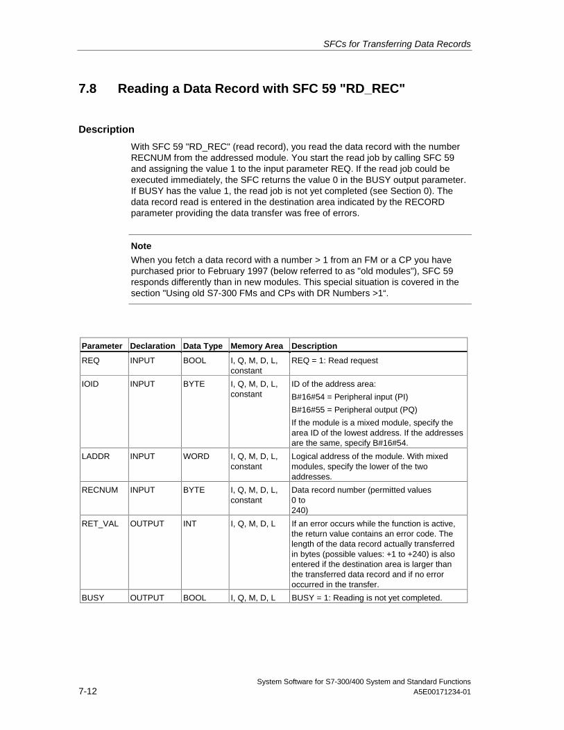
SFCs for Transferring Data Records
System Software for S7-300/400 System and Standard Functions7-12 A5E00171234-01
7.8 Reading a Data Record with SFC 59 "RD_REC"
Description
With SFC 59 "RD_REC" (read record), you read the data record with the numberRECNUM from the addressed module. You start the read job by calling SFC 59and assigning the value 1 to the input parameter REQ. If the read job could beexecuted immediately, the SFC returns the value 0 in the BUSY output parameter.If BUSY has the value 1, the read job is not yet completed (see Section 0). Thedata record read is entered in the destination area indicated by the RECORDparameter providing the data transfer was free of errors.
Note
When you fetch a data record with a number > 1 from an FM or a CP you havepurchased prior to February 1997 (below referred to as "old modules"), SFC 59responds differently than in new modules. This special situation is covered in thesection "Using old S7-300 FMs and CPs with DR Numbers >1“.
Parameter Declaration Data Type Memory Area Description
REQ INPUT BOOL I, Q, M, D, L,constant
REQ = 1: Read request
IOID INPUT BYTE I, Q, M, D, L,constant
ID of the address area:
B#16#54 = Peripheral input (PI)
B#16#55 = Peripheral output (PQ)
If the module is a mixed module, specify thearea ID of the lowest address. If the addressesare the same, specify B#16#54.
LADDR INPUT WORD I, Q, M, D, L,constant
Logical address of the module. With mixedmodules, specify the lower of the twoaddresses.
RECNUM INPUT BYTE I, Q, M, D, L,constant
Data record number (permitted values0 to240)
RET_VAL OUTPUT INT I, Q, M, D, L If an error occurs while the function is active,the return value contains an error code. Thelength of the data record actually transferredin bytes (possible values: +1 to +240) is alsoentered if the destination area is larger thanthe transferred data record and if no erroroccurred in the transfer.
BUSY OUTPUT BOOL I, Q, M, D, L BUSY = 1: Reading is not yet completed.
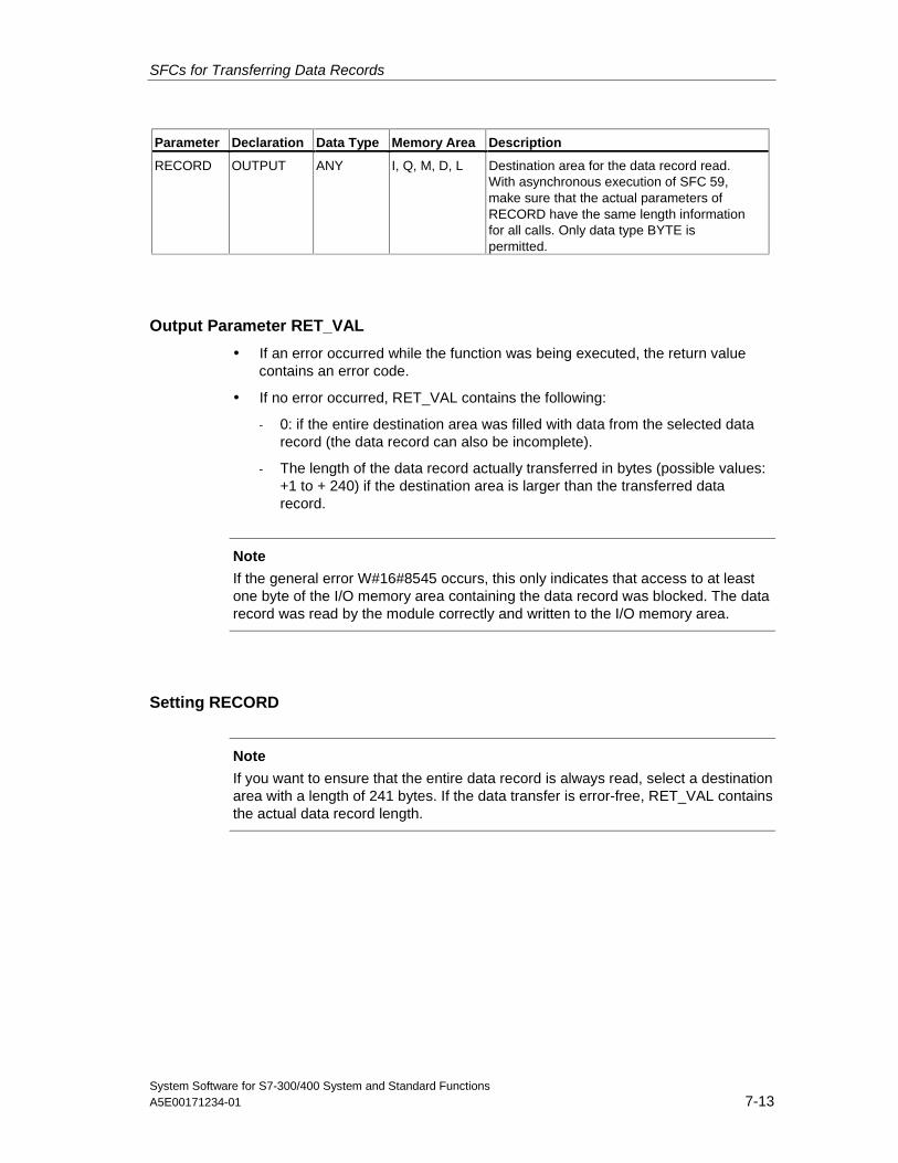
SFCs for Transferring Data Records
System Software for S7-300/400 System and Standard FunctionsA5E00171234-01 7-13
Parameter Declaration Data Type Memory Area Description
RECORD OUTPUT ANY I, Q, M, D, L Destination area for the data record read.With asynchronous execution of SFC 59,make sure that the actual parameters ofRECORD have the same length informationfor all calls. Only data type BYTE ispermitted.
Output Parameter RET_VAL
• If an error occurred while the function was being executed, the return valuecontains an error code.
• If no error occurred, RET_VAL contains the following:
- 0: if the entire destination area was filled with data from the selected datarecord (the data record can also be incomplete).
- The length of the data record actually transferred in bytes (possible values:+1 to + 240) if the destination area is larger than the transferred datarecord.
Note
If the general error W#16#8545 occurs, this only indicates that access to at leastone byte of the I/O memory area containing the data record was blocked. The datarecord was read by the module correctly and written to the I/O memory area.
Setting RECORD
Note
If you want to ensure that the entire data record is always read, select a destinationarea with a length of 241 bytes. If the data transfer is error-free, RET_VAL containsthe actual data record length.
SFCs for Transferring Data Records
System Software for S7-300/400 System and Standard Functions7-14 A5E00171234-01
Using Old S7-300 FMs and CPs with Data Record Numbers > 1
If you want to read out a data record with a number higher than 1 from an oldS7-300 FM or old S7-300 CP using SFC 59 "RD_REC," remember the followingpoints:
• If the destination area is larger than the actual length of the required datarecord, no data are entered in RECORD.RET_VAL has the value W#16#80B1.
• If the destination area is smaller than the actual length of the required datarecord, the CPU reads as many bytes beginning at the start of the record asare specified in the length information of RECORD and enters this number ofbytes in RECORD.RET_VAL has the value 0.
• If the length specified in RECORD is the same as the actual length of therequired data record, the CPU reads the data record and enters it in RECORD.RET_VAL has the value 0.
Error Information
The "real" error information (error codes W#16#8xyz) in the following table can bedivided into two classes:
• Temporary errors (error codes W#16#80A2 to 80A4, 80Cx):With this type of error, it is possible that the error will be eliminated without youtaking any action, in other words, it is advisable to call the SFC again (ifnecessary, more than once).An example of a temporary error is when required resources are currentlybeing used (W#16#80C3).
• Permanent errors (error codes W#16#809x, 80A1, 80Bx, 80Dx):This type of error will not be eliminated without you taking action. Calling theSFC again will only be successful after the error has been eliminated. Anexample of a permanent error is entering the wrong length in RECORD(W#16#80B1).
Note
If you transfer data records to a DPV1 slave with SFC58 "WR_REC" or if you fetchdata records from a DPV1 slave with SFC59 "RD_REC" and if this DPV1 slaveoperates in DPV1 mode, the DP Master evaluates the error information it receivedfrom the Slave as follows:
If the error information lies within the range from W#16#8000 to W#16#80FF orW#16#F000 to W#16#FFFF the DP master passes the error information to theSFC. If it lies out of this range, the CPU passes the value W#16#80A2 to the SFCand suspends the slave.
For a description of the error information received from DPV1-Slaves, seeReceiving an Interrupt from a DP-Slave with SFB 54 "RALRM" STATUS[3].
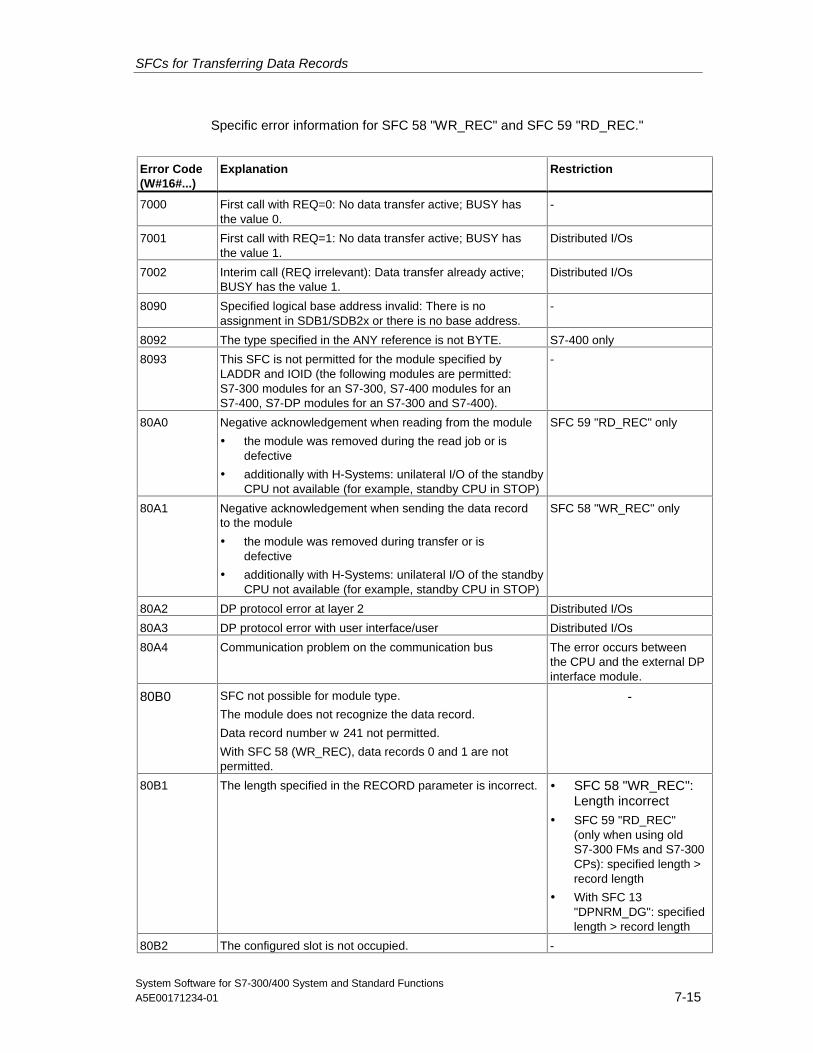
SFCs for Transferring Data Records
System Software for S7-300/400 System and Standard FunctionsA5E00171234-01 7-15
Specific error information for SFC 58 "WR_REC" and SFC 59 "RD_REC."
Error Code(W#16#...)
Explanation Restriction
7000 First call with REQ=0: No data transfer active; BUSY hasthe value 0.
-
7001 First call with REQ=1: No data transfer active; BUSY hasthe value 1.
Distributed I/Os
7002 Interim call (REQ irrelevant): Data transfer already active;BUSY has the value 1.
Distributed I/Os
8090 Specified logical base address invalid: There is noassignment in SDB1/SDB2x or there is no base address.
-
8092 The type specified in the ANY reference is not BYTE. S7-400 only
8093 This SFC is not permitted for the module specified byLADDR and IOID (the following modules are permitted:S7-300 modules for an S7-300, S7-400 modules for anS7-400, S7-DP modules for an S7-300 and S7-400).
-
80A0 Negative acknowledgement when reading from the module
• the module was removed during the read job or isdefective
• additionally with H-Systems: unilateral I/O of the standbyCPU not available (for example, standby CPU in STOP)
SFC 59 "RD_REC" only
80A1 Negative acknowledgement when sending the data recordto the module
• the module was removed during transfer or isdefective
• additionally with H-Systems: unilateral I/O of the standbyCPU not available (for example, standby CPU in STOP)
SFC 58 "WR_REC" only
80A2 DP protocol error at layer 2 Distributed I/Os
80A3 DP protocol error with user interface/user Distributed I/Os
80A4 Communication problem on the communication bus The error occurs betweenthe CPU and the external DPinterface module.
80B0 SFC not possible for module type.
The module does not recognize the data record.
Data record number w 241 not permitted.
With SFC 58 (WR_REC), data records 0 and 1 are notpermitted.
-
80B1 The length specified in the RECORD parameter is incorrect. • SFC 58 "WR_REC":Length incorrect
• SFC 59 "RD_REC"(only when using oldS7-300 FMs and S7-300CPs): specified length >record length
• With SFC 13"DPNRM_DG": specifiedlength > record length
80B2 The configured slot is not occupied. -
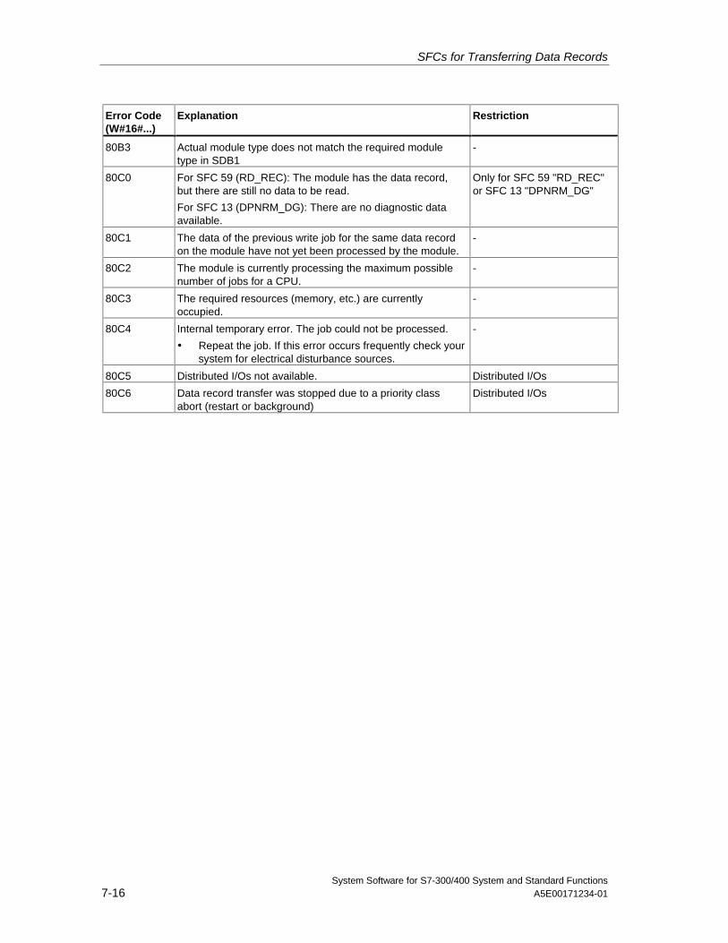
SFCs for Transferring Data Records
System Software for S7-300/400 System and Standard Functions7-16 A5E00171234-01
Error Code(W#16#...)
Explanation Restriction
80B3 Actual module type does not match the required moduletype in SDB1
-
80C0 For SFC 59 (RD_REC): The module has the data record,but there are still no data to be read.
For SFC 13 (DPNRM_DG): There are no diagnostic dataavailable.
Only for SFC 59 "RD_REC"or SFC 13 "DPNRM_DG"
80C1 The data of the previous write job for the same data recordon the module have not yet been processed by the module.
-
80C2 The module is currently processing the maximum possiblenumber of jobs for a CPU.
-
80C3 The required resources (memory, etc.) are currentlyoccupied.
-
80C4 Internal temporary error. The job could not be processed.
• Repeat the job. If this error occurs frequently check yoursystem for electrical disturbance sources.
-
80C5 Distributed I/Os not available. Distributed I/Os
80C6 Data record transfer was stopped due to a priority classabort (restart or background)
Distributed I/Os
SFCs for Transferring Data Records
System Software for S7-300/400 System and Standard FunctionsA5E00171234-01 7-17
7.9 Further Error Information for SFCs 55 to 59
S7-400 only
With the S7-400, the SFCs 55 to 59 can also return the error informationW#16#80Fx. In this case an error occurred that could not be localized. Pleasecontact the maintenance department in this case.

SFCs for Transferring Data Records
System Software for S7-300/400 System and Standard Functions7-18 A5E00171234-01
System Software for S7-300/400 System and Standard FunctionsA5E00171234-01 8-1
8 DPV1 SFBs According to PNO AK 1131
8.1 Reading a Data Record from a DP Slave with SFB 52"RDREC"
Note
The SFB52 "RDREC" interface is identical to the FB "RDREC" defined in thestandard "PROFIBUS Guideline PROFIBUS Communication and Proxy FunctionBlocks according to IEC 61131-3".
Description
With the SFB52 "RDREC" (read record) you read a data record with the numberINDEX from a DP Slave component (module or modules) that has been addressedvia ID.
Specify the maximum number of bytes you want to read in MLEN. The selectedlength of the target area RECORD should have at least the length of MLEN bytes.
TRUE on output parameter VALID verifies that the data record has beensuccessfully transferred into the target area RECORD. In this case, the outputparameter LEN contains the length of the fetched data in bytes.
The output parameter ERROR indicates whether a data record transmission errorhas occurred. In this case, the output parameter STATUS contains the errorinformation.
Operating principle
The SFC 52 "RDREC" operates asynchronously, that is, processing coversmultiple SFC calls. Start the job by calling SFC52 with REQ = 1.
The job status is displayed via the output parameter BUSY and bytes 2 and 3 ofoutput parameter STATUS. Here, the STATUS bytes 2 and 3 correspond with theoutput parameter RET_VAL of the asynchronously operating SFCs (see alsoMeaning of REQ, RET_VAL and BUSY with Asynchronously Operating SFCs).
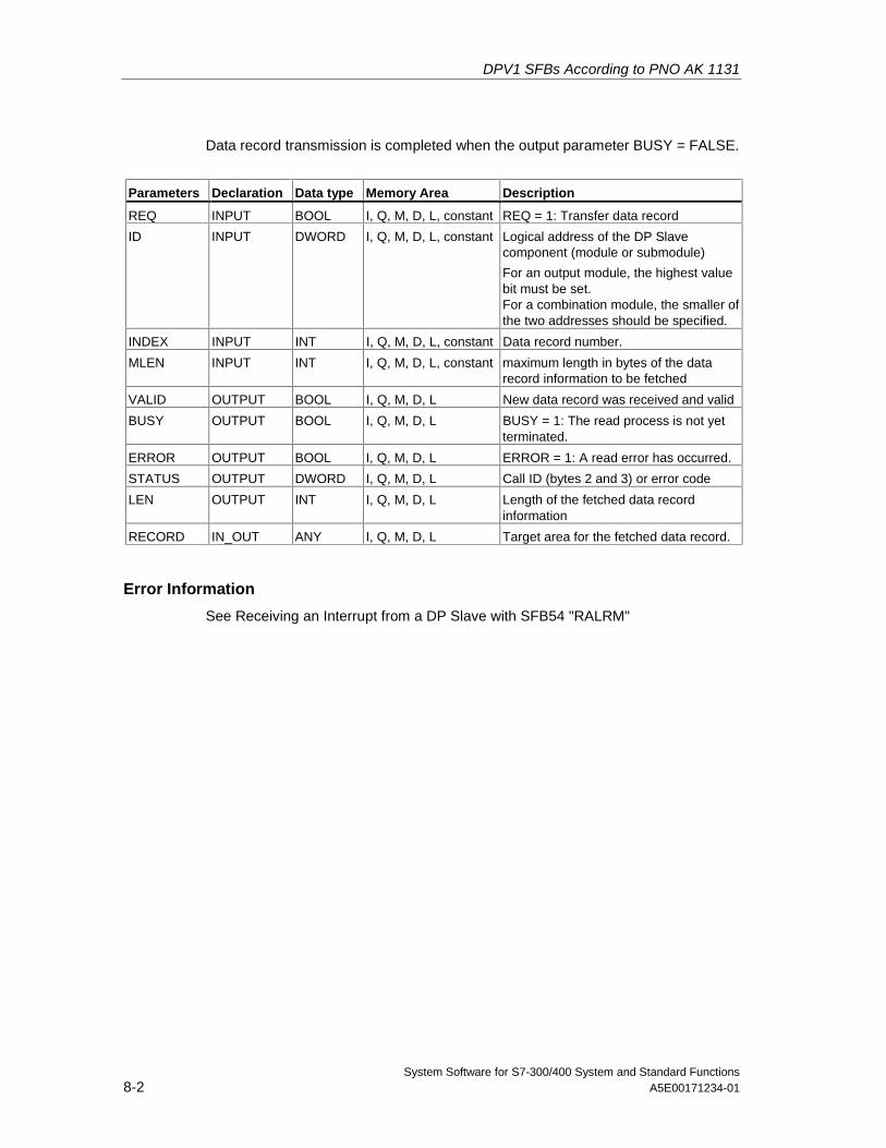
DPV1 SFBs According to PNO AK 1131
System Software for S7-300/400 System and Standard Functions8-2 A5E00171234-01
Data record transmission is completed when the output parameter BUSY = FALSE.
Parameters Declaration Data type Memory Area Description
REQ INPUT BOOL I, Q, M, D, L, constant REQ = 1: Transfer data record
ID INPUT DWORD I, Q, M, D, L, constant Logical address of the DP Slavecomponent (module or submodule)
For an output module, the highest valuebit must be set.For a combination module, the smaller ofthe two addresses should be specified.
INDEX INPUT INT I, Q, M, D, L, constant Data record number.
MLEN INPUT INT I, Q, M, D, L, constant maximum length in bytes of the datarecord information to be fetched
VALID OUTPUT BOOL I, Q, M, D, L New data record was received and valid
BUSY OUTPUT BOOL I, Q, M, D, L BUSY = 1: The read process is not yetterminated.
ERROR OUTPUT BOOL I, Q, M, D, L ERROR = 1: A read error has occurred.
STATUS OUTPUT DWORD I, Q, M, D, L Call ID (bytes 2 and 3) or error code
LEN OUTPUT INT I, Q, M, D, L Length of the fetched data recordinformation
RECORD IN_OUT ANY I, Q, M, D, L Target area for the fetched data record.
Error Information
See Receiving an Interrupt from a DP Slave with SFB54 "RALRM"
DPV1 SFBs According to PNO AK 1131
System Software for S7-300/400 System and Standard FunctionsA5E00171234-01 8-3
8.2 Writing a Data Record in a DP Slave with SFB53"WRREC"
Note
The SFB52 "WRREC" interface is identical to the FB "WRREC" defined in thestandard "PROFIBUS Guideline PROFIBUS Communication and Proxy FunctionBlocks according to IEC 61131-3"
Description
With the SFB52 "WRREC" (write record) you transfer a data record with thenumber INDEX to a DP Slave component (module) that has been addressed viaID.
Specify the byte length of the data record to be transmitted. The selected length ofthe source area RECORD should, therefore, have at least the length of LEN bytes.
TRUE on output parameter DONE verifies that the data record has beensuccessfully transferred to the DP Slave.
The output parameter ERROR indicates whether a data record transmission errorhas occurred. In this case, the output parameter STATUS contains the errorinformation.
Operating principle
The SFC 53 "WRREC" operates asynchronously, that is, processing coversmultiple SFC calls. Start the job by calling SFC53 with REQ = 1.
The job status is displayed via the output parameter BUSY and bytes 2 and 3 ofoutput parameter STATUS. Here, the STATUS bytes 2 and 3 correspond with theoutput parameter RET_VAL of the asynchronously operating SFCs (see alsoMeaning of REQ, RET_VAL and BUSY with Asynchronously Operating SFCs).
Please note that you must assign the same value to the actual parameter ofRECORD for all SFB53 calls that belong to one and the same job. The sameapplies to the LEN parameters.
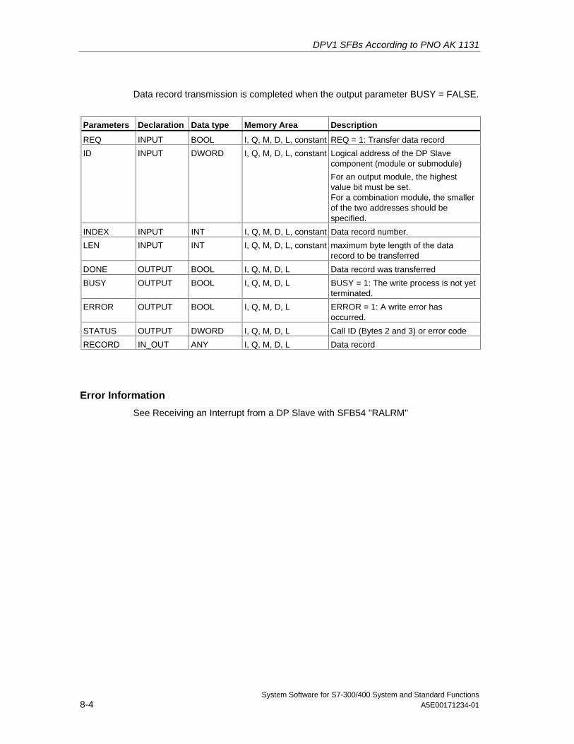
DPV1 SFBs According to PNO AK 1131
System Software for S7-300/400 System and Standard Functions8-4 A5E00171234-01
Data record transmission is completed when the output parameter BUSY = FALSE.
Parameters Declaration Data type Memory Area Description
REQ INPUT BOOL I, Q, M, D, L, constant REQ = 1: Transfer data record
ID INPUT DWORD I, Q, M, D, L, constant Logical address of the DP Slavecomponent (module or submodule)
For an output module, the highestvalue bit must be set.For a combination module, the smallerof the two addresses should bespecified.
INDEX INPUT INT I, Q, M, D, L, constant Data record number.
LEN INPUT INT I, Q, M, D, L, constant maximum byte length of the datarecord to be transferred
DONE OUTPUT BOOL I, Q, M, D, L Data record was transferred
BUSY OUTPUT BOOL I, Q, M, D, L BUSY = 1: The write process is not yetterminated.
ERROR OUTPUT BOOL I, Q, M, D, L ERROR = 1: A write error hasoccurred.
STATUS OUTPUT DWORD I, Q, M, D, L Call ID (Bytes 2 and 3) or error code
RECORD IN_OUT ANY I, Q, M, D, L Data record
Error Information
See Receiving an Interrupt from a DP Slave with SFB54 "RALRM"
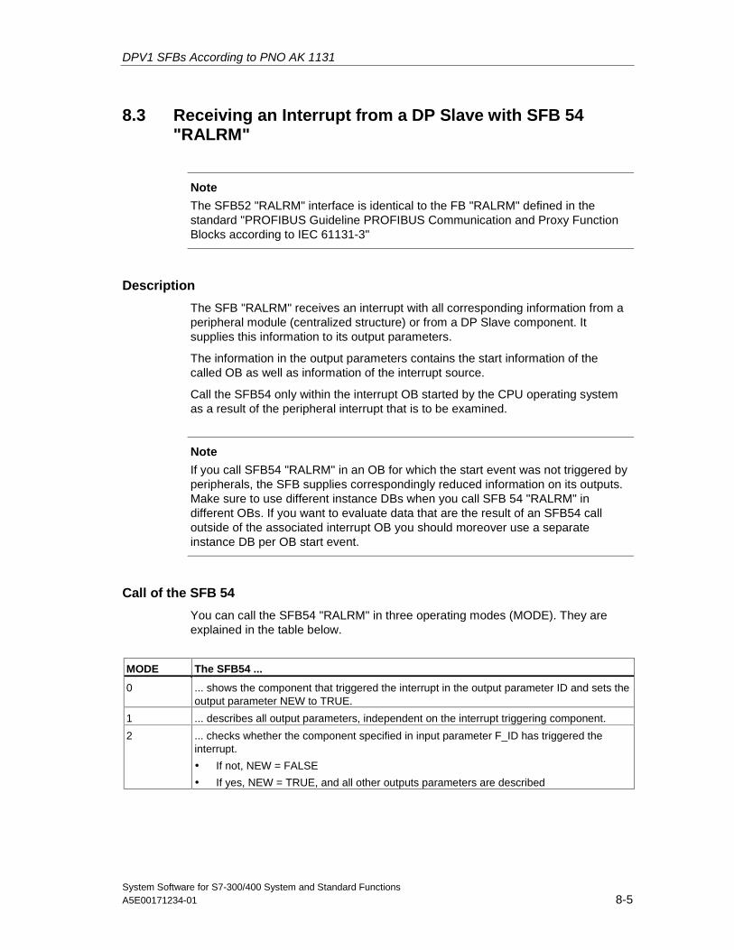
DPV1 SFBs According to PNO AK 1131
System Software for S7-300/400 System and Standard FunctionsA5E00171234-01 8-5
8.3 Receiving an Interrupt from a DP Slave with SFB 54"RALRM"
Note
The SFB52 "RALRM" interface is identical to the FB "RALRM" defined in thestandard "PROFIBUS Guideline PROFIBUS Communication and Proxy FunctionBlocks according to IEC 61131-3"
Description
The SFB "RALRM" receives an interrupt with all corresponding information from aperipheral module (centralized structure) or from a DP Slave component. Itsupplies this information to its output parameters.
The information in the output parameters contains the start information of thecalled OB as well as information of the interrupt source.
Call the SFB54 only within the interrupt OB started by the CPU operating systemas a result of the peripheral interrupt that is to be examined.
Note
If you call SFB54 "RALRM" in an OB for which the start event was not triggered byperipherals, the SFB supplies correspondingly reduced information on its outputs.Make sure to use different instance DBs when you call SFB 54 "RALRM" indifferent OBs. If you want to evaluate data that are the result of an SFB54 calloutside of the associated interrupt OB you should moreover use a separateinstance DB per OB start event.
Call of the SFB 54
You can call the SFB54 "RALRM" in three operating modes (MODE). They areexplained in the table below.
MODE The SFB54 ...
0 ... shows the component that triggered the interrupt in the output parameter ID and sets theoutput parameter NEW to TRUE.
1 ... describes all output parameters, independent on the interrupt triggering component.
2 ... checks whether the component specified in input parameter F_ID has triggered theinterrupt.
• If not, NEW = FALSE
• If yes, NEW = TRUE, and all other outputs parameters are described
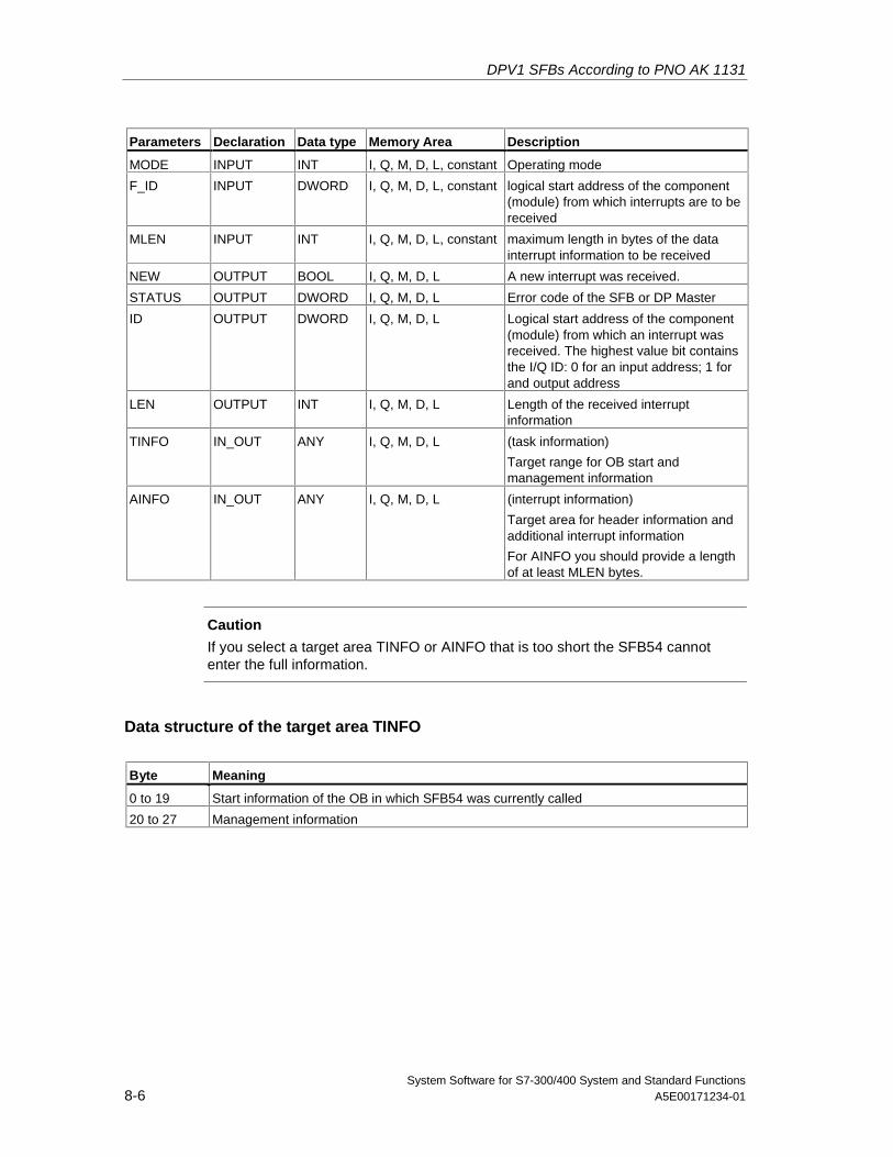
DPV1 SFBs According to PNO AK 1131
System Software for S7-300/400 System and Standard Functions8-6 A5E00171234-01
Parameters Declaration Data type Memory Area Description
MODE INPUT INT I, Q, M, D, L, constant Operating mode
F_ID INPUT DWORD I, Q, M, D, L, constant logical start address of the component(module) from which interrupts are to bereceived
MLEN INPUT INT I, Q, M, D, L, constant maximum length in bytes of the datainterrupt information to be received
NEW OUTPUT BOOL I, Q, M, D, L A new interrupt was received.
STATUS OUTPUT DWORD I, Q, M, D, L Error code of the SFB or DP Master
ID OUTPUT DWORD I, Q, M, D, L Logical start address of the component(module) from which an interrupt wasreceived. The highest value bit containsthe I/Q ID: 0 for an input address; 1 forand output address
LEN OUTPUT INT I, Q, M, D, L Length of the received interruptinformation
TINFO IN_OUT ANY I, Q, M, D, L (task information)
Target range for OB start andmanagement information
AINFO IN_OUT ANY I, Q, M, D, L (interrupt information)
Target area for header information andadditional interrupt information
For AINFO you should provide a lengthof at least MLEN bytes.
Caution
If you select a target area TINFO or AINFO that is too short the SFB54 cannotenter the full information.
Data structure of the target area TINFO
Byte Meaning
0 to 19 Start information of the OB in which SFB54 was currently called
20 to 27 Management information
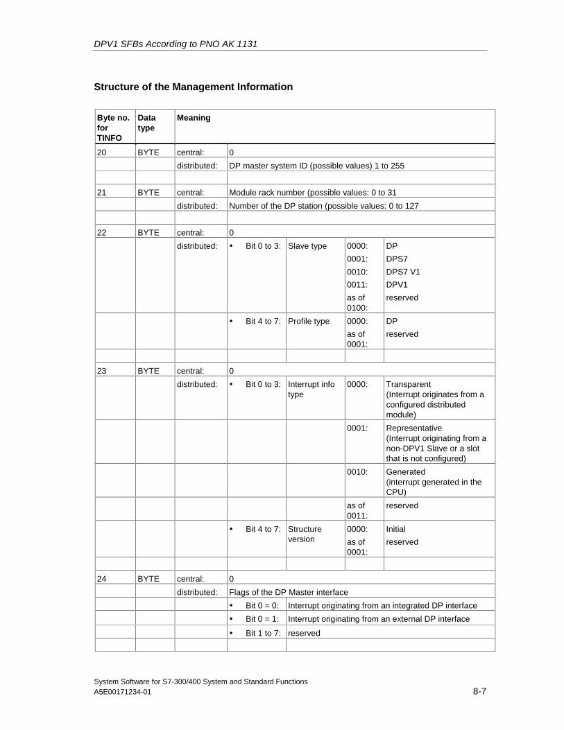
DPV1 SFBs According to PNO AK 1131
System Software for S7-300/400 System and Standard FunctionsA5E00171234-01 8-7
Structure of the Management Information
Byte no.forTINFO
Datatype
Meaning
20 BYTE central: 0
distributed: DP master system ID (possible values) 1 to 255
21 BYTE central: Module rack number (possible values: 0 to 31
distributed: Number of the DP station (possible values: 0 to 127
22 BYTE central: 0
distributed: • Bit 0 to 3: Slave type 0000:
0001:
0010:
0011:
as of0100:
DP
DPS7
DPS7 V1
DPV1
reserved
• Bit 4 to 7: Profile type 0000:
as of0001:
DP
reserved
23 BYTE central: 0
distributed: • Bit 0 to 3: Interrupt infotype
0000: Transparent(Interrupt originates from aconfigured distributedmodule)
0001: Representative(Interrupt originating from anon-DPV1 Slave or a slotthat is not configured)
0010: Generated(interrupt generated in theCPU)
as of0011:
reserved
• Bit 4 to 7: Structureversion
0000:
as of0001:
Initial
reserved
24 BYTE central: 0
distributed: Flags of the DP Master interface
• Bit 0 = 0: Interrupt originating from an integrated DP interface
• Bit 0 = 1: Interrupt originating from an external DP interface
• Bit 1 to 7: reserved
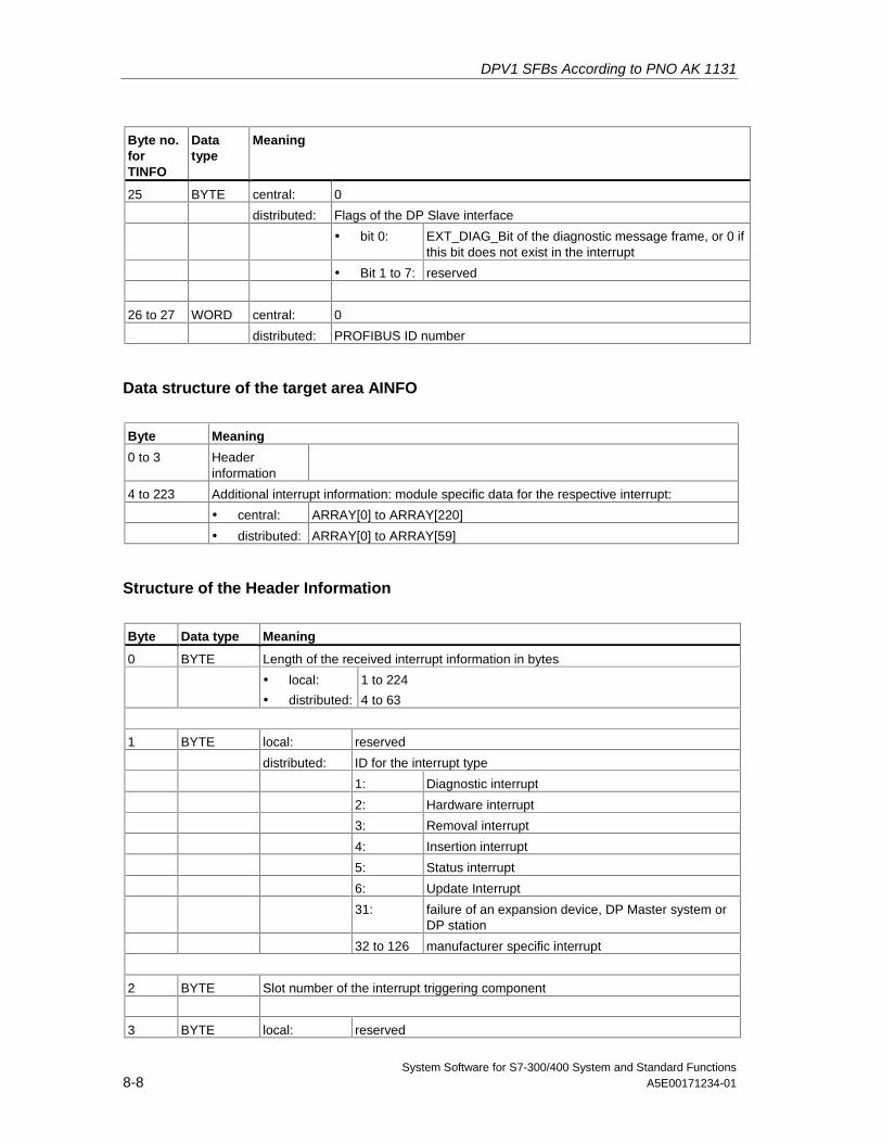
DPV1 SFBs According to PNO AK 1131
System Software for S7-300/400 System and Standard Functions8-8 A5E00171234-01
Byte no.forTINFO
Datatype
Meaning
25 BYTE central: 0
distributed: Flags of the DP Slave interface
• bit 0: EXT_DIAG_Bit of the diagnostic message frame, or 0 ifthis bit does not exist in the interrupt
• Bit 1 to 7: reserved
26 to 27 WORD central: 0
distributed: PROFIBUS ID number
Data structure of the target area AINFO
Byte Meaning
0 to 3 Headerinformation
4 to 223 Additional interrupt information: module specific data for the respective interrupt:
• central: ARRAY[0] to ARRAY[220]
• distributed: ARRAY[0] to ARRAY[59]
Structure of the Header Information
Byte Data type Meaning
0 BYTE Length of the received interrupt information in bytes
• local:
• distributed:
1 to 224
4 to 63
1 BYTE local: reserved
distributed: ID for the interrupt type
1: Diagnostic interrupt
2: Hardware interrupt
3: Removal interrupt
4: Insertion interrupt
5: Status interrupt
6: Update Interrupt
31: failure of an expansion device, DP Master system orDP station
32 to 126 manufacturer specific interrupt
2 BYTE Slot number of the interrupt triggering component
3 BYTE local: reserved
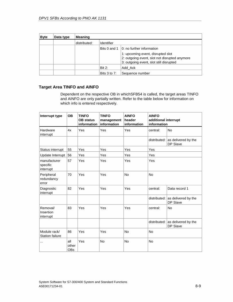
DPV1 SFBs According to PNO AK 1131
System Software for S7-300/400 System and Standard FunctionsA5E00171234-01 8-9
Byte Data type Meaning
distributed: Identifier
Bits 0 and 1 0: no further information
1: upcoming event, disrupted slot2: outgoing event, slot not disrupted anymore3: outgoing event, slot still disrupted
Bit 2: Add_Ack
Bits 3 to 7: Sequence number
Target Area TINFO and AINFO
Dependent on the respective OB in whichSFB54 is called, the target areas TINFOand AINFO are only partially written. Refer to the table below for information onwhich info is entered respectively.
Interrupt type OB TINFOOB statusinformation
TINFOmanagementinformation
AINFOheaderinformation
AINFOadditional interruptinformation
Hardwareinterrupt
4x Yes Yes Yes central: No
distributed: as delivered by theDP Slave
Status interrupt 55 Yes Yes Yes Yes
Update Interrupt 56 Yes Yes Yes Yes
manufacturerspecificinterrupt
57 Yes Yes Yes Yes
Peripheralredundancyerror
70 Yes Yes No No
Diagnosticinterrupt
82 Yes Yes Yes central: Data record 1
distributed: as delivered by theDP Slave
Removal/Insertioninterrupt
83 Yes Yes Yes central: No
distributed: as delivered by theDP Slave
Module rack/Station failure
86 Yes Yes No No
... allotherOBs
Yes No No No
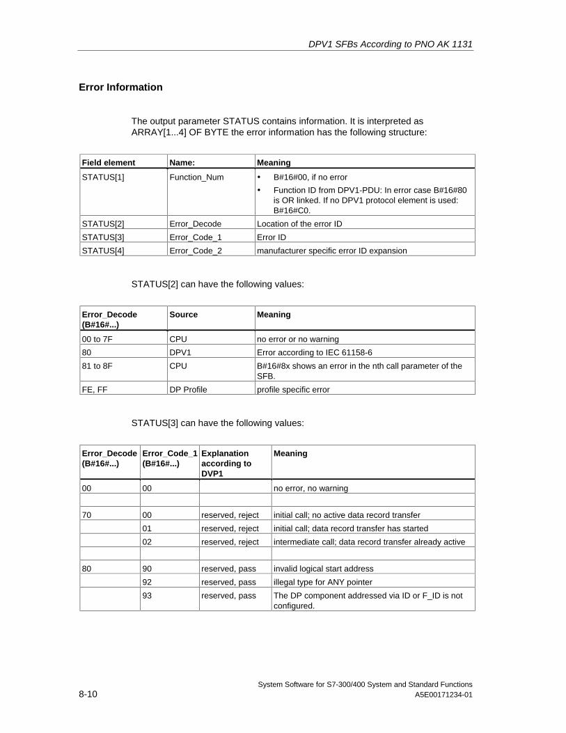
DPV1 SFBs According to PNO AK 1131
System Software for S7-300/400 System and Standard Functions8-10 A5E00171234-01
Error Information
The output parameter STATUS contains information. It is interpreted asARRAY[1...4] OF BYTE the error information has the following structure:
Field element Name: Meaning
STATUS[1] Function_Num • B#16#00, if no error
• Function ID from DPV1-PDU: In error case B#16#80is OR linked. If no DPV1 protocol element is used:B#16#C0.
STATUS[2] Error_Decode Location of the error ID
STATUS[3] Error_Code_1 Error ID
STATUS[4] Error_Code_2 manufacturer specific error ID expansion
STATUS[2] can have the following values:
Error_Decode(B#16#...)
Source Meaning
00 to 7F CPU no error or no warning
80 DPV1 Error according to IEC 61158-6
81 to 8F CPU B#16#8x shows an error in the nth call parameter of theSFB.
FE, FF DP Profile profile specific error
STATUS[3] can have the following values:
Error_Decode(B#16#...)
Error_Code_1(B#16#...)
Explanationaccording toDVP1
Meaning
00 00 no error, no warning
70 00 reserved, reject initial call; no active data record transfer
01 reserved, reject initial call; data record transfer has started
02 reserved, reject intermediate call; data record transfer already active
80 90 reserved, pass invalid logical start address
92 reserved, pass illegal type for ANY pointer
93 reserved, pass The DP component addressed via ID or F_ID is notconfigured.
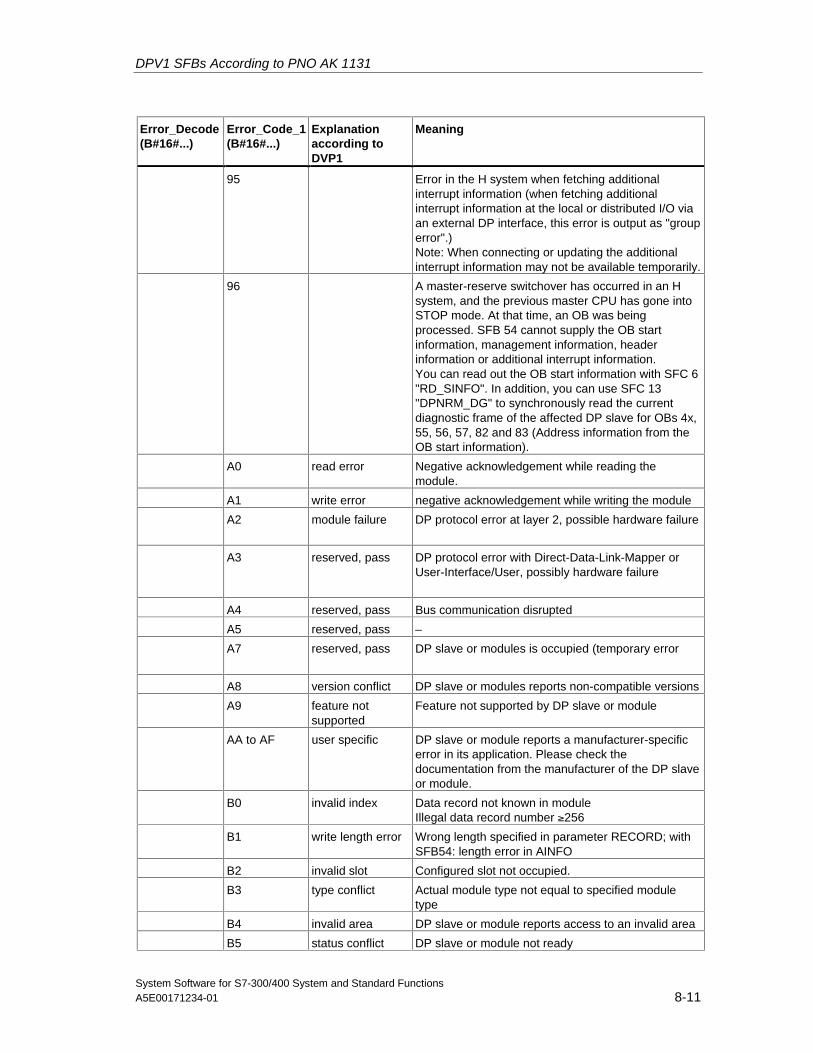
DPV1 SFBs According to PNO AK 1131
System Software for S7-300/400 System and Standard FunctionsA5E00171234-01 8-11
Error_Decode(B#16#...)
Error_Code_1(B#16#...)
Explanationaccording toDVP1
Meaning
95 Error in the H system when fetching additionalinterrupt information (when fetching additionalinterrupt information at the local or distributed I/O viaan external DP interface, this error is output as "grouperror".)Note: When connecting or updating the additionalinterrupt information may not be available temporarily.
96 A master-reserve switchover has occurred in an Hsystem, and the previous master CPU has gone intoSTOP mode. At that time, an OB was beingprocessed. SFB 54 cannot supply the OB startinformation, management information, headerinformation or additional interrupt information.You can read out the OB start information with SFC 6"RD_SINFO". In addition, you can use SFC 13"DPNRM_DG" to synchronously read the currentdiagnostic frame of the affected DP slave for OBs 4x,55, 56, 57, 82 and 83 (Address information from theOB start information).
A0 read error Negative acknowledgement while reading themodule.
A1 write error negative acknowledgement while writing the module
A2 module failure DP protocol error at layer 2, possible hardware failure
A3 reserved, pass DP protocol error with Direct-Data-Link-Mapper orUser-Interface/User, possibly hardware failure
A4 reserved, pass Bus communication disrupted
A5 reserved, pass –
A7 reserved, pass DP slave or modules is occupied (temporary error
A8 version conflict DP slave or modules reports non-compatible versions
A9 feature notsupported
Feature not supported by DP slave or module
AA to AF user specific DP slave or module reports a manufacturer-specificerror in its application. Please check thedocumentation from the manufacturer of the DP slaveor module.
B0 invalid index Data record not known in moduleIllegal data record number ≥256
B1 write length error Wrong length specified in parameter RECORD; withSFB54: length error in AINFO
B2 invalid slot Configured slot not occupied.
B3 type conflict Actual module type not equal to specified moduletype
B4 invalid area DP slave or module reports access to an invalid area
B5 status conflict DP slave or module not ready
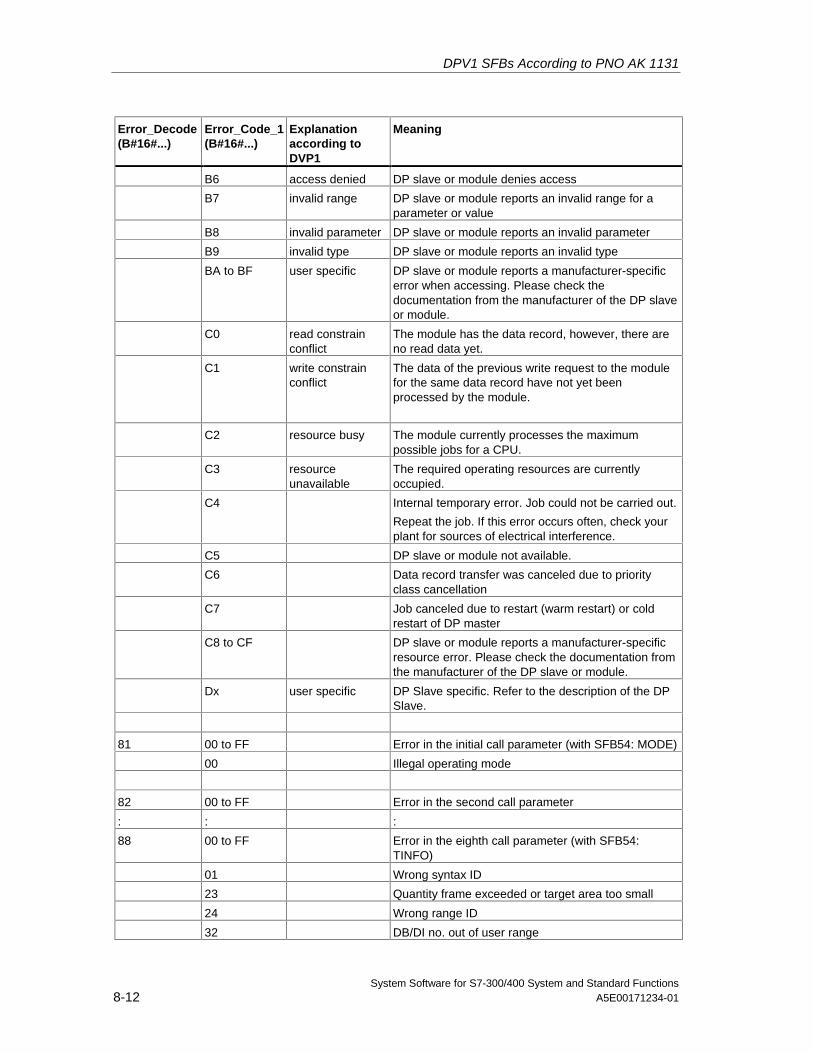
DPV1 SFBs According to PNO AK 1131
System Software for S7-300/400 System and Standard Functions8-12 A5E00171234-01
Error_Decode(B#16#...)
Error_Code_1(B#16#...)
Explanationaccording toDVP1
Meaning
B6 access denied DP slave or module denies access
B7 invalid range DP slave or module reports an invalid range for aparameter or value
B8 invalid parameter DP slave or module reports an invalid parameter
B9 invalid type DP slave or module reports an invalid type
BA to BF user specific DP slave or module reports a manufacturer-specificerror when accessing. Please check thedocumentation from the manufacturer of the DP slaveor module.
C0 read constrainconflict
The module has the data record, however, there areno read data yet.
C1 write constrainconflict
The data of the previous write request to the modulefor the same data record have not yet beenprocessed by the module.
C2 resource busy The module currently processes the maximumpossible jobs for a CPU.
C3 resourceunavailable
The required operating resources are currentlyoccupied.
C4 Internal temporary error. Job could not be carried out.
Repeat the job. If this error occurs often, check yourplant for sources of electrical interference.
C5 DP slave or module not available.
C6 Data record transfer was canceled due to priorityclass cancellation
C7 Job canceled due to restart (warm restart) or coldrestart of DP master
C8 to CF DP slave or module reports a manufacturer-specificresource error. Please check the documentation fromthe manufacturer of the DP slave or module.
Dx user specific DP Slave specific. Refer to the description of the DPSlave.
81 00 to FF Error in the initial call parameter (with SFB54: MODE)
00 Illegal operating mode
82 00 to FF Error in the second call parameter
: : :
88 00 to FF Error in the eighth call parameter (with SFB54:TINFO)
01 Wrong syntax ID
23 Quantity frame exceeded or target area too small
24 Wrong range ID
32 DB/DI no. out of user range
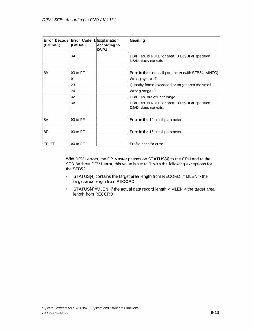
DPV1 SFBs According to PNO AK 1131
System Software for S7-300/400 System and Standard FunctionsA5E00171234-01 8-13
Error_Decode(B#16#...)
Error_Code_1(B#16#...)
Explanationaccording toDVP1
Meaning
3A DB/DI no. is NULL for area ID DB/DI or specifiedDB/DI does not exist
89 00 to FF Error in the ninth call parameter (with SFB54: AINFO)
01 Wrong syntax ID
23 Quantity frame exceeded or target area too small
24 Wrong range ID
32 DB/DI no. out of user range
3A DB/DI no. is NULL for area ID DB/DI or specifiedDB/DI does not exist
8A 00 to FF Error in the 10th call parameter
: : :
8F 00 to FF Error in the 15th call parameter
FE, FF 00 to FF Profile-specific error
With DPV1 errors, the DP Master passes on STATUS[4] to the CPU and to theSFB. Without DPV1 error, this value is set to 0, with the following exceptions forthe SFB52:
• STATUS[4] contains the target area length from RECORD, if MLEN > thetarget area length from RECORD
• STATUS[4]=MLEN, if the actual data record length < MLEN < the target arealength from RECORD
DPV1 SFBs According to PNO AK 1131
System Software for S7-300/400 System and Standard Functions8-14 A5E00171234-01
8.4 Sending an Interrupt to the DP Master with SFB 75"SALRM"
Note
The SFB 75 "SALRM" interface is identical to the FB "SALRM" defined in thestandard "PROFIBUS Guideline PROFIBUS Communication and Proxy FunctionBlocks according to IEC 61131-3"
Description
SFB 75 "SALRM" sends an interrupt for a slot from the user program of anintelligent slave to the associated DP master, which accesses it in the transitionalarea (virtual slot). This starts the associated OB at the DP master.
You can send additional interrupt-specific information along with the interrupt. Atthe DP master, you can use SFB 54 "RALRM" to read all the additional information.
SFB 75 can only be used in S7-compatible mode.
• DP: The master uses a GSD file to integrate the I-slave.
• S7-compatible: The I-slave is linked to a master in STEP 7 via HW Config.
Operating principle
SFB 75 "SALRM" is an is an asynchronous SFB, which means that its processingextends over several SFB calls. Call SFB 75 with REQ = 1 to start the transfer ofthe interrupt.
The send procedure remains active until interrupt processing is eitheracknowledged or canceled by the DP master.
Output parameter BUSY and bytes 2 and 3 of the output parameter STATUSindicate the job status, whereby STATUS bytes 2 and 3 correspond to theRET_VAL output parameter of the asynchronously operating SFCs (see alsoMeaning of the Parameters REQ, RET_VAL and BUSY with Asynchronous SFCs
The transfer of the interrupt is concluded when the output parameter BUSY =FALSE.
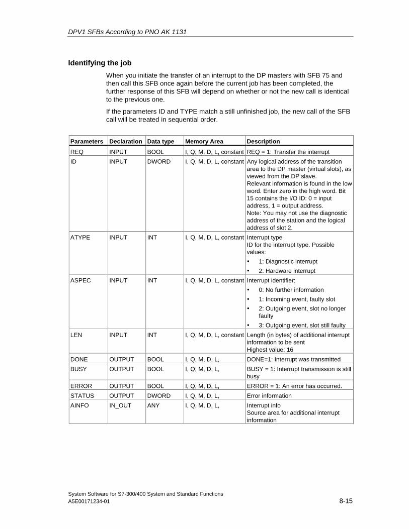
DPV1 SFBs According to PNO AK 1131
System Software for S7-300/400 System and Standard FunctionsA5E00171234-01 8-15
Identifying the job
When you initiate the transfer of an interrupt to the DP masters with SFB 75 andthen call this SFB once again before the current job has been completed, thefurther response of this SFB will depend on whether or not the new call is identicalto the previous one.
If the parameters ID and TYPE match a still unfinished job, the new call of the SFBcall will be treated in sequential order.
Parameters Declaration Data type Memory Area Description
REQ INPUT BOOL I, Q, M, D, L, constant REQ = 1: Transfer the interrupt
ID INPUT DWORD I, Q, M, D, L, constant Any logical address of the transitionarea to the DP master (virtual slots), asviewed from the DP slave.Relevant information is found in the lowword. Enter zero in the high word. Bit15 contains the I/O ID: 0 = inputaddress, 1 = output address.Note: You may not use the diagnosticaddress of the station and the logicaladdress of slot 2.
ATYPE INPUT INT I, Q, M, D, L, constant Interrupt typeID for the interrupt type. Possiblevalues:
• 1: Diagnostic interrupt
• 2: Hardware interrupt
ASPEC INPUT INT I, Q, M, D, L, constant Interrupt identifier:
• 0: No further information
• 1: Incoming event, faulty slot
• 2: Outgoing event, slot no longer faulty
• 3: Outgoing event, slot still faulty
LEN INPUT INT I, Q, M, D, L, constant Length (in bytes) of additional interruptinformation to be sentHighest value: 16
DONE OUTPUT BOOL I, Q, M, D, L, DONE=1: Interrupt was transmitted
BUSY OUTPUT BOOL I, Q, M, D, L, BUSY = 1: Interrupt transmission is stillbusy
ERROR OUTPUT BOOL I, Q, M, D, L, ERROR = 1: An error has occurred.
STATUS OUTPUT DWORD I, Q, M, D, L, Error information
AINFO IN_OUT ANY I, Q, M, D, L, Interrupt infoSource area for additional interruptinformation
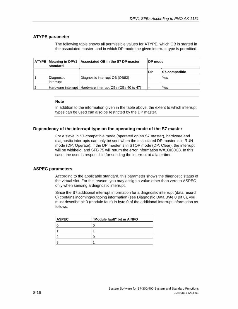
DPV1 SFBs According to PNO AK 1131
System Software for S7-300/400 System and Standard Functions8-16 A5E00171234-01
ATYPE parameter
The following table shows all permissible values for ATYPE, which OB is started inthe associated master, and in which DP mode the given interrupt type is permitted.
ATYPE Meaning in DPV1standard
Associated OB in the S7 DP master DP mode
DP S7-compatible
1 Diagnosticinterrupt
Diagnostic interrupt OB (OB82) – Yes
2 Hardware interrupt Hardware interrupt OBs (OBs 40 to 47) – Yes
Note
In addition to the information given in the table above, the extent to which interrupttypes can be used can also be restricted by the DP master.
Dependency of the interrupt type on the operating mode of the S7 master
For a slave in S7-compatible mode (operated on an S7 master), hardware anddiagnostic interrupts can only be sent when the associated DP master is in RUNmode (DP: Operate). If the DP master is in STOP mode (DP: Clear), the interruptwill be withheld, and SFB 75 will return the error information W#16#80C8. In thiscase, the user is responsible for sending the interrupt at a later time.
ASPEC parameters
According to the applicable standard, this parameter shows the diagnostic status ofthe virtual slot. For this reason, you may assign a value other than zero to ASPEConly when sending a diagnostic interrupt.
Since the S7 additional interrupt information for a diagnostic interrupt (data record0) contains incoming/outgoing information (see Diagnostic Data Byte 0 Bit 0), youmust describe bit 0 (module fault) in byte 0 of the additional interrupt information asfollows:
ASPEC "Module fault" bit in AINFO
0 0
1 1
2 0
3 1
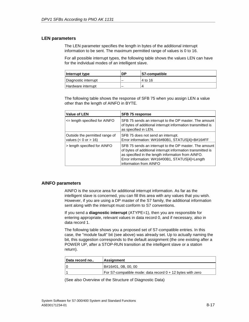
DPV1 SFBs According to PNO AK 1131
System Software for S7-300/400 System and Standard FunctionsA5E00171234-01 8-17
LEN parameters
The LEN parameter specifies the length in bytes of the additional interruptinformation to be sent. The maximum permitted range of values is 0 to 16.
For all possible interrupt types, the following table shows the values LEN can havefor the individual modes of an intelligent slave.
Interrupt type DP S7-compatible
Diagnostic interrupt – 4 to 16
Hardware interrupt – 4
The following table shows the response of SFB 75 when you assign LEN a valueother than the length of AINFO in BYTE.
Value of LEN SFB 75 response
<= length specified for AINFO SFB 75 sends an interrupt to the DP master. The amountof bytes of additional interrupt information transmitted isas specified in LEN.
Outside the permitted range ofvalues (< 0 or > 16)
SFB 75 does not send an interrupt.Error information: W#16#80B1, STATUS[4]=B#16#FF
> length specified for AINFO SFB 75 sends an interrupt to the DP master. The amountof bytes of additional interrupt information transmitted isas specified in the length information from AINFO.Error information: W#16#00B1, STATUS[4]=Lengthinformation from AINFO
AINFO parameters
AINFO is the source area for additional interrupt information. As far as theintelligent slave is concerned, you can fill this area with any values that you wish.However, if you are using a DP master of the S7 family, the additional informationsent along with the interrupt must conform to S7 conventions.
If you send a diagnostic interrupt (ATYPE=1), then you are responsible forentering appropriate, relevant values in data record 0, and if necessary, also indata record 1.
The following table shows you a proposed set of S7-compatible entries. In thiscase, the "module fault" bit (see above) was already set. Up to actually naming thebit, this suggestion corresponds to the default assignment (the one existing after aPOWER UP, after a STOP-RUN transition at the intelligent slave or a stationreturn).
Data record no.. Assignment
0 B#16#01, 0B, 00, 00
1 For S7-compatible mode: data record 0 + 12 bytes with zero
(See also Overview of the Structure of Diagnostic Data)
DPV1 SFBs According to PNO AK 1131
System Software for S7-300/400 System and Standard Functions8-18 A5E00171234-01
Effect of the SFB75 call on the module status information and the group errorLED (SF)
As for any CPU, the slot properties for an intelligent slave are stored in the modulestatus information (see SSL-ID W#16#xy91 - Module Status Information)
When you use SFB 75 to send a diagnostic interrupt, the operating system at theintelligent slave influences the slave-local module status information and the SFLED based on bit 0 in byte 0 in AINFO (this bit is added to the status information as"module fault"). However, there is no diagnostic buffer entry made at the I slave,and no diagnostic interrupt OB is started.
Consistency of module status information between DP master and I slave
The following section presents different scenarios and discusses their effects onmodule status information:
• Station return (results in start of OB 86 at DP master and at I slave)This has an effect on the module status information at the I slave and at the S7master ("Module fault" is reset.). If, after a station return, there are faults at theI slave from the point of view of the user, these must be reported to the DPmaster by means of an SFB 75 call.
• STOP-RUN operating mode transition at the DP master (results in start of OB82 at I slave)The module status information at the I slave remains unchanged. The DPmaster resets the "module fault" bit in the relevant module status information.
To ensure consistency of the module status information between the DPmaster and the I slave in S7- compatible mode, you must react at the I slave asfollows:
- For each error-free virtual slot, use SFB 75 to send an outgoing diagnosticinterrupt to the DP master.
- For each faulty virtual slot, use SFB 75 to send an incoming diagnosticinterrupt to the DP master.
• STOP-RUN operating mode transition at the I slave (results in start of OB 82 atDP master)The module status information at the DP master remains unchanged; theinformation at the I slave is reset ("Module fault" is reset.).To ensure consistency of the module status information between the DPmaster and the I slave in S7- compatible mode, you must react at the I slave asfollows:
- For each error-free virtual slot, use SFB 75 to send an outgoing diagnosticinterrupt to the DP master.
- For each faulty virtual slot, use SFB 75 to send an incoming diagnosticinterrupt to the DP master.
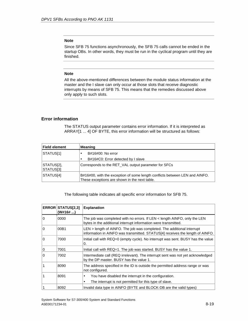
DPV1 SFBs According to PNO AK 1131
System Software for S7-300/400 System and Standard FunctionsA5E00171234-01 8-19
Note
Since SFB 75 functions asynchronously, the SFB 75 calls cannot be ended in thestartup OBs. In other words, they must be run in the cyclical program until they arefinished.
Note
All the above-mentioned differences between the module status information at themaster and the I slave can only occur at those slots that receive diagnosticinterrupts by means of SFB 75. This means that the remedies discussed aboveonly apply to such slots.
Error information
The STATUS output parameter contains error information. If it is interpreted asARRAY[1 ... 4] OF BYTE, this error information will be structured as follows:
Field element Meaning
STATUS[1] • B#16#00: No error
• B#16#C0: Error detected by I slave
STATUS[2],STATUS[3]
Corresponds to the RET_VAL output parameter for SFCs
STATUS[4] B#16#00, with the exception of some length conflicts between LEN and AINFO.These exceptions are shown in the next table.
The following table indicates all specific error information for SFB 75.
ERROR STATUS[2,3](W#16# ...)
Explanation
0 0000 The job was completed with no errors. If LEN < length AINFO, only the LENbytes in the additional interrupt information were transmitted.
0 00B1 LEN > length of AINFO. The job was completed. The additional interruptinformation in AINFO was transmitted. STATUS[4] receives the length of AINFO.
0 7000 Initial call with REQ=0 (empty cycle). No interrupt was sent. BUSY has the value0.
0 7001 Initial call with REQ=1. The job was started. BUSY has the value 1.
0 7002 Intermediate call (REQ irrelevant). The interrupt sent was not yet acknowledgedby the DP master. BUSY has the value 1.
1 8090 The address specified in the ID is outside the permitted address range or wasnot configured.
1 8091 • You have disabled the interrupt in the configuration.
• The interrupt is not permitted for this type of slave.
1 8092 Invalid data type in AINFO (BYTE and BLOCK-DB are the valid types)
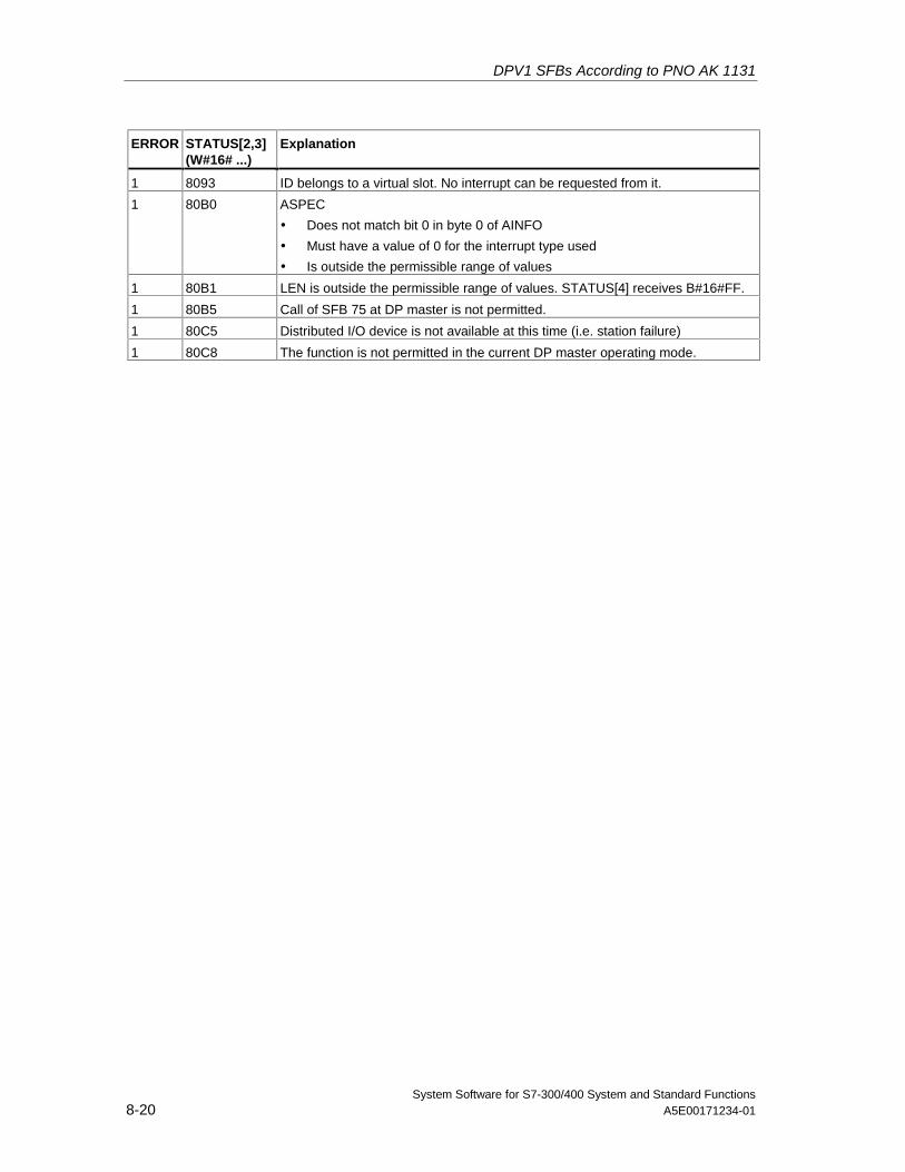
DPV1 SFBs According to PNO AK 1131
System Software for S7-300/400 System and Standard Functions8-20 A5E00171234-01
ERROR STATUS[2,3](W#16# ...)
Explanation
1 8093 ID belongs to a virtual slot. No interrupt can be requested from it.
1 80B0 ASPEC
• Does not match bit 0 in byte 0 of AINFO
• Must have a value of 0 for the interrupt type used
• Is outside the permissible range of values
1 80B1 LEN is outside the permissible range of values. STATUS[4] receives B#16#FF.
1 80B5 Call of SFB 75 at DP master is not permitted.
1 80C5 Distributed I/O device is not available at this time (i.e. station failure)
1 80C8 The function is not permitted in the current DP master operating mode.
System Software for S7-300/400 System and Standard FunctionsA5E00171234-01 9-1
9 SFCs for Handling Time-of-Day Interrupts
9.1 Handling Time-of-Day Interrupts
Definition
A time-of-day interrupt results in one of the time-of-day interrupt OBs (OB10 toOB17) being called.
Conditions for the Call
Before a time-of-day interrupt OB can be called by the operating system, thefollowing conditions must be met:
• The time-of-day interrupt OB must have parameters assigned to it (start dateand time, execution) using either
- STEP 7 or
- SFC 28 "SET_TINT" in the user program.
• The time-of-day interrupt OB must be activated using
- STEP 7 or
- SFC 30 "ACT_TINT" in the user program.
• The time-of-day interrupt OB must not be deselected with STEP 7.
• The time-of-day interrupt OB must exist in the CPU.
• If you set the interrupt with SFC 30 "ACT_TINT" and if you have specified theexecution of the OB as once only, the start date and time must not yet havepassed. If you have selected periodic execution, the time-of-day interrupt OBwill be called when the next period is completed (start time + multiple of thespecified period).
Hint
You can assign parameters to the time-of-day interrupt using STEP 7 and thenactivate the interrupt in your user program (SFC 30 "ACT_TINT").
Purpose of SFC 28 to SFC 31
The system functions SFC 28 to SFC 31 described in the following sections areused as follows:
• To set time-of-day interrupts (SFC 28 "SET_TINT")
• To cancel time-of-day interrupts (SFC 29 "CAN_TINT")
• To activate time-of-day interrupts (SFC 30 "ACT_TINT")
• To query time-of-day interrupts (SFC 31 "QRY_TINT")
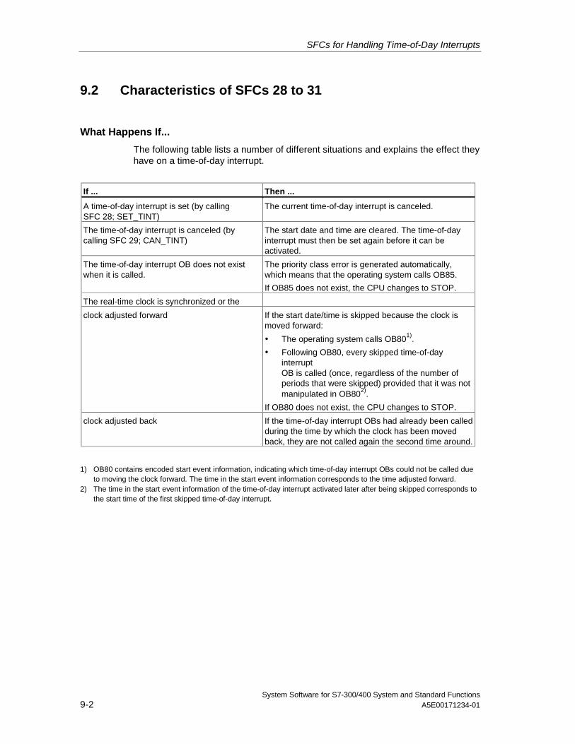
SFCs for Handling Time-of-Day Interrupts
System Software for S7-300/400 System and Standard Functions9-2 A5E00171234-01
9.2 Characteristics of SFCs 28 to 31
What Happens If...
The following table lists a number of different situations and explains the effect theyhave on a time-of-day interrupt.
If ... Then ...
A time-of-day interrupt is set (by callingSFC 28; SET_TINT)
The current time-of-day interrupt is canceled.
The time-of-day interrupt is canceled (bycalling SFC 29; CAN_TINT)
The start date and time are cleared. The time-of-dayinterrupt must then be set again before it can beactivated.
The time-of-day interrupt OB does not existwhen it is called.
The priority class error is generated automatically,which means that the operating system calls OB85.
If OB85 does not exist, the CPU changes to STOP.
The real-time clock is synchronized or the
clock adjusted forward If the start date/time is skipped because the clock ismoved forward:
• The operating system calls OB801).
• Following OB80, every skipped time-of-dayinterruptOB is called (once, regardless of the number ofperiods that were skipped) provided that it was notmanipulated in OB802).
If OB80 does not exist, the CPU changes to STOP.
clock adjusted back If the time-of-day interrupt OBs had already been calledduring the time by which the clock has been movedback, they are not called again the second time around.
1) OB80 contains encoded start event information, indicating which time-of-day interrupt OBs could not be called dueto moving the clock forward. The time in the start event information corresponds to the time adjusted forward.
2) The time in the start event information of the time-of-day interrupt activated later after being skipped corresponds tothe start time of the first skipped time-of-day interrupt.
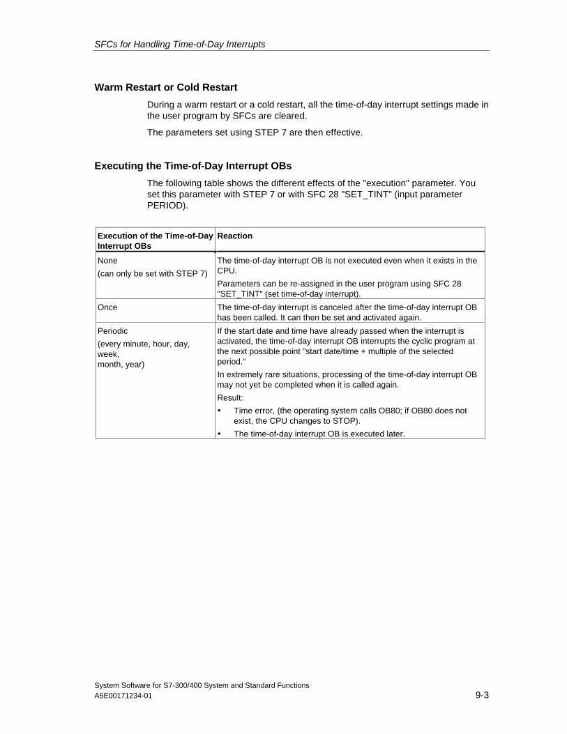
SFCs for Handling Time-of-Day Interrupts
System Software for S7-300/400 System and Standard FunctionsA5E00171234-01 9-3
Warm Restart or Cold Restart
During a warm restart or a cold restart, all the time-of-day interrupt settings made inthe user program by SFCs are cleared.
The parameters set using STEP 7 are then effective.
Executing the Time-of-Day Interrupt OBs
The following table shows the different effects of the "execution" parameter. Youset this parameter with STEP 7 or with SFC 28 "SET_TINT" (input parameterPERIOD).
Execution of the Time-of-DayInterrupt OBs
Reaction
None
(can only be set with STEP 7)
The time-of-day interrupt OB is not executed even when it exists in theCPU.
Parameters can be re-assigned in the user program using SFC 28"SET_TINT" (set time-of-day interrupt).
Once The time-of-day interrupt is canceled after the time-of-day interrupt OBhas been called. It can then be set and activated again.
Periodic
(every minute, hour, day,week,month, year)
If the start date and time have already passed when the interrupt isactivated, the time-of-day interrupt OB interrupts the cyclic program atthe next possible point "start date/time + multiple of the selectedperiod."
In extremely rare situations, processing of the time-of-day interrupt OBmay not yet be completed when it is called again.
Result:
• Time error, (the operating system calls OB80; if OB80 does notexist, the CPU changes to STOP).
• The time-of-day interrupt OB is executed later.
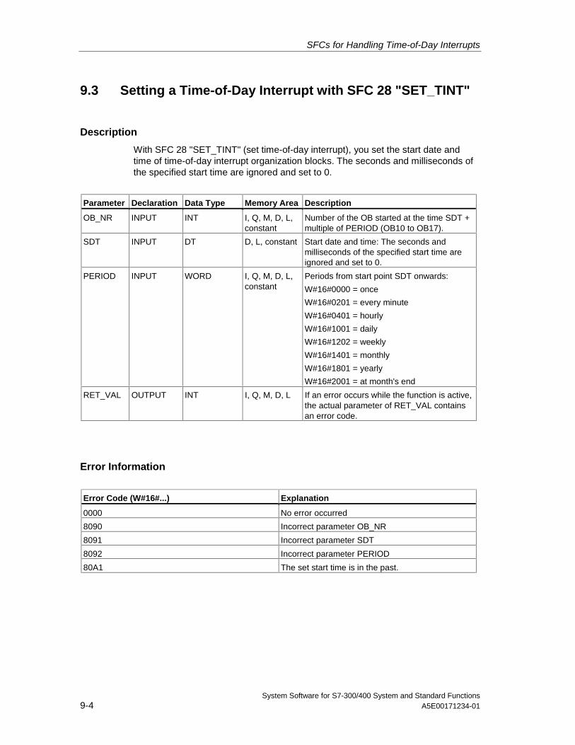
SFCs for Handling Time-of-Day Interrupts
System Software for S7-300/400 System and Standard Functions9-4 A5E00171234-01
9.3 Setting a Time-of-Day Interrupt with SFC 28 "SET_TINT"
Description
With SFC 28 "SET_TINT" (set time-of-day interrupt), you set the start date andtime of time-of-day interrupt organization blocks. The seconds and milliseconds ofthe specified start time are ignored and set to 0.
Parameter Declaration Data Type Memory Area Description
OB_NR INPUT INT I, Q, M, D, L,constant
Number of the OB started at the time SDT +multiple of PERIOD (OB10 to OB17).
SDT INPUT DT D, L, constant Start date and time: The seconds andmilliseconds of the specified start time areignored and set to 0.
PERIOD INPUT WORD I, Q, M, D, L,constant
Periods from start point SDT onwards:
W#16#0000 = once
W#16#0201 = every minute
W#16#0401 = hourly
W#16#1001 = daily
W#16#1202 = weekly
W#16#1401 = monthly
W#16#1801 = yearly
W#16#2001 = at month's end
RET_VAL OUTPUT INT I, Q, M, D, L If an error occurs while the function is active,the actual parameter of RET_VAL containsan error code.
Error Information
Error Code (W#16#...) Explanation
0000 No error occurred
8090 Incorrect parameter OB_NR
8091 Incorrect parameter SDT
8092 Incorrect parameter PERIOD
80A1 The set start time is in the past.
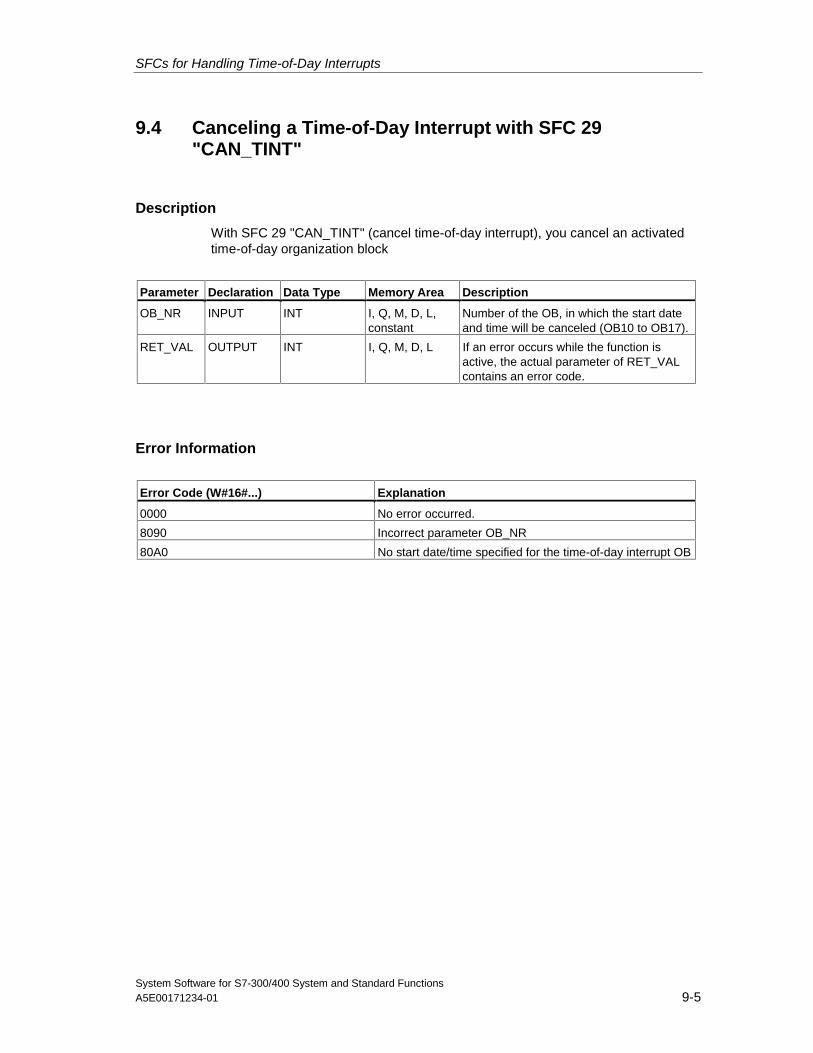
SFCs for Handling Time-of-Day Interrupts
System Software for S7-300/400 System and Standard FunctionsA5E00171234-01 9-5
9.4 Canceling a Time-of-Day Interrupt with SFC 29"CAN_TINT"
Description
With SFC 29 "CAN_TINT" (cancel time-of-day interrupt), you cancel an activatedtime-of-day organization block
Parameter Declaration Data Type Memory Area Description
OB_NR INPUT INT I, Q, M, D, L,constant
Number of the OB, in which the start dateand time will be canceled (OB10 to OB17).
RET_VAL OUTPUT INT I, Q, M, D, L If an error occurs while the function isactive, the actual parameter of RET_VALcontains an error code.
Error Information
Error Code (W#16#...) Explanation
0000 No error occurred.
8090 Incorrect parameter OB_NR
80A0 No start date/time specified for the time-of-day interrupt OB
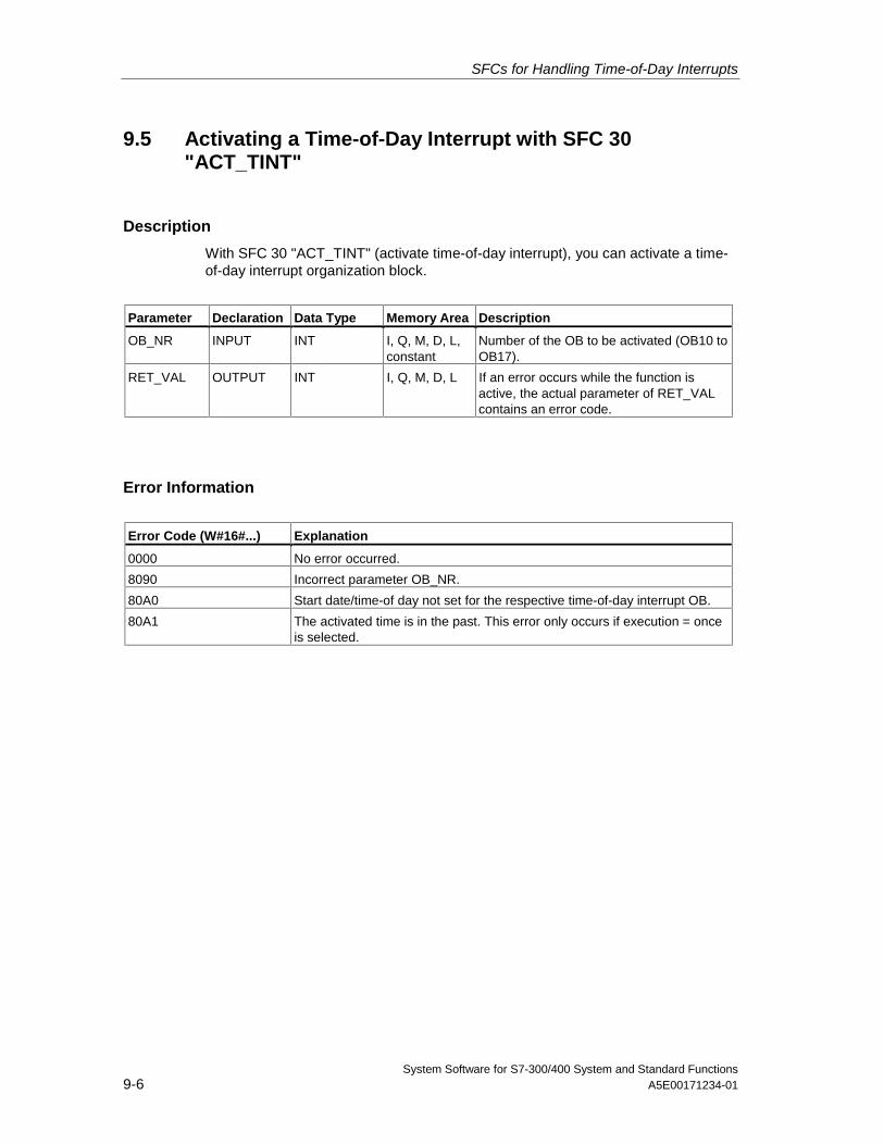
SFCs for Handling Time-of-Day Interrupts
System Software for S7-300/400 System and Standard Functions9-6 A5E00171234-01
9.5 Activating a Time-of-Day Interrupt with SFC 30"ACT_TINT"
Description
With SFC 30 "ACT_TINT" (activate time-of-day interrupt), you can activate a time-of-day interrupt organization block.
Parameter Declaration Data Type Memory Area Description
OB_NR INPUT INT I, Q, M, D, L,constant
Number of the OB to be activated (OB10 toOB17).
RET_VAL OUTPUT INT I, Q, M, D, L If an error occurs while the function isactive, the actual parameter of RET_VALcontains an error code.
Error Information
Error Code (W#16#...) Explanation
0000 No error occurred.
8090 Incorrect parameter OB_NR.
80A0 Start date/time-of day not set for the respective time-of-day interrupt OB.
80A1 The activated time is in the past. This error only occurs if execution = onceis selected.
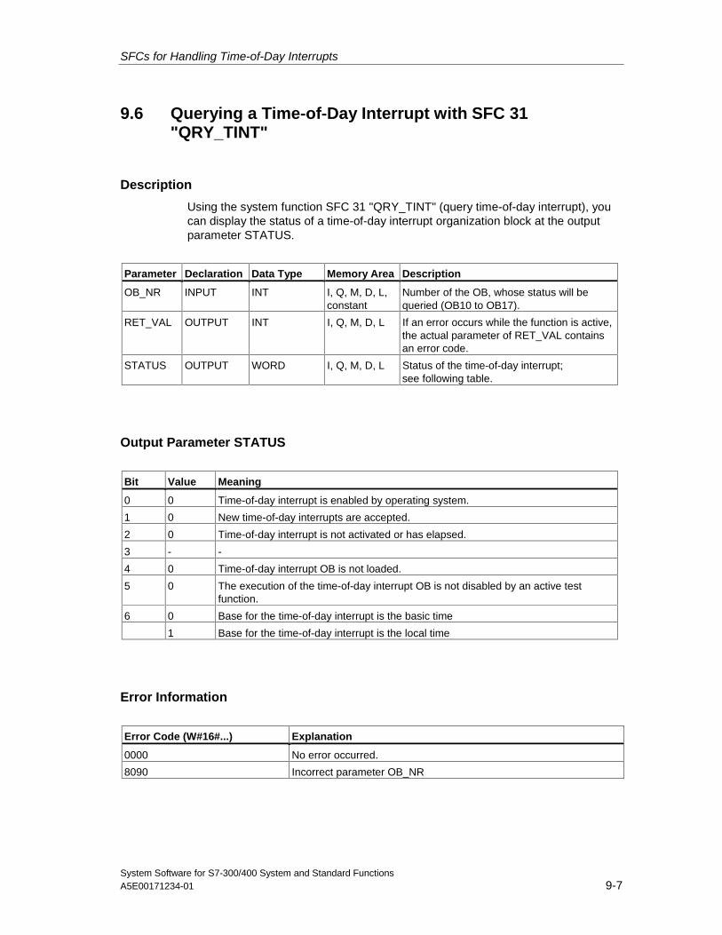
SFCs for Handling Time-of-Day Interrupts
System Software for S7-300/400 System and Standard FunctionsA5E00171234-01 9-7
9.6 Querying a Time-of-Day Interrupt with SFC 31"QRY_TINT"
Description
Using the system function SFC 31 "QRY_TINT" (query time-of-day interrupt), youcan display the status of a time-of-day interrupt organization block at the outputparameter STATUS.
Parameter Declaration Data Type Memory Area Description
OB_NR INPUT INT I, Q, M, D, L,constant
Number of the OB, whose status will bequeried (OB10 to OB17).
RET_VAL OUTPUT INT I, Q, M, D, L If an error occurs while the function is active,the actual parameter of RET_VAL containsan error code.
STATUS OUTPUT WORD I, Q, M, D, L Status of the time-of-day interrupt;see following table.
Output Parameter STATUS
Bit Value Meaning
0 0 Time-of-day interrupt is enabled by operating system.
1 0 New time-of-day interrupts are accepted.
2 0 Time-of-day interrupt is not activated or has elapsed.
3 - -
4 0 Time-of-day interrupt OB is not loaded.
5 0 The execution of the time-of-day interrupt OB is not disabled by an active testfunction.
6 0 Base for the time-of-day interrupt is the basic time
1 Base for the time-of-day interrupt is the local time
Error Information
Error Code (W#16#...) Explanation
0000 No error occurred.
8090 Incorrect parameter OB_NR

SFCs for Handling Time-of-Day Interrupts
System Software for S7-300/400 System and Standard Functions9-8 A5E00171234-01
System Software for S7-300/400 System and Standard FunctionsA5E00171234-01 10-1
10 SFCs for Handling Time-Delay Interrupts
10.1 Handling Time-Delay Interrupts
Definition
After you have called SFC 32 "SRT_DINT," the operating system generates aninterrupt after the specified delay time has elapsed, in other words, the selectedtime-delay interrupt OB is called. This interrupt is known as a time-delay interrupt.
Conditions for the Call
Before a time-delay interrupt OB can be called by the operating system, thefollowing conditions must be met:
• The time-delay interrupt OB must be started by SFC 32 "SRT_DINT."
• The time-delay interrupt OB must not be deselected with STEP 7.
• The time-delay interrupt OB must exist in the CPU.
Purpose of SFC 32 to SFC 34
The system functions SFC 32 to SFC 34 described in the following sections areused as follows:
• To start time-delay interrupts (SFC 32 "SRT_DINT")
• To cancel time-delay interrupts (SFC 33 "CAN_DINT")
• To query time-delay interrupts (SFC 34 "QRY_DINT").
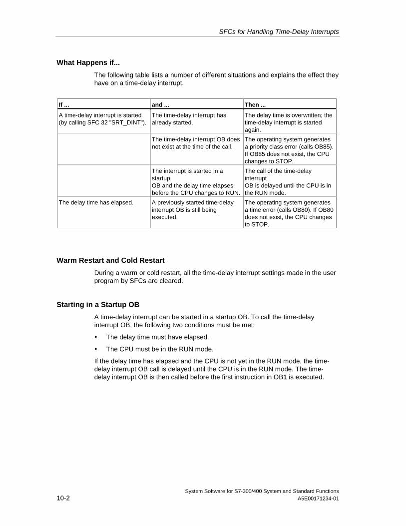
SFCs for Handling Time-Delay Interrupts
System Software for S7-300/400 System and Standard Functions10-2 A5E00171234-01
What Happens if...
The following table lists a number of different situations and explains the effect theyhave on a time-delay interrupt.
If ... and ... Then ...
A time-delay interrupt is started(by calling SFC 32 "SRT_DINT").
The time-delay interrupt hasalready started.
The delay time is overwritten; thetime-delay interrupt is startedagain.
The time-delay interrupt OB doesnot exist at the time of the call.
The operating system generatesa priority class error (calls OB85).If OB85 does not exist, the CPUchanges to STOP.
The interrupt is started in astartupOB and the delay time elapsesbefore the CPU changes to RUN.
The call of the time-delayinterruptOB is delayed until the CPU is inthe RUN mode.
The delay time has elapsed. A previously started time-delayinterrupt OB is still beingexecuted.
The operating system generatesa time error (calls OB80). If OB80does not exist, the CPU changesto STOP.
Warm Restart and Cold Restart
During a warm or cold restart, all the time-delay interrupt settings made in the userprogram by SFCs are cleared.
Starting in a Startup OB
A time-delay interrupt can be started in a startup OB. To call the time-delayinterrupt OB, the following two conditions must be met:
• The delay time must have elapsed.
• The CPU must be in the RUN mode.
If the delay time has elapsed and the CPU is not yet in the RUN mode, the time-delay interrupt OB call is delayed until the CPU is in the RUN mode. The time-delay interrupt OB is then called before the first instruction in OB1 is executed.
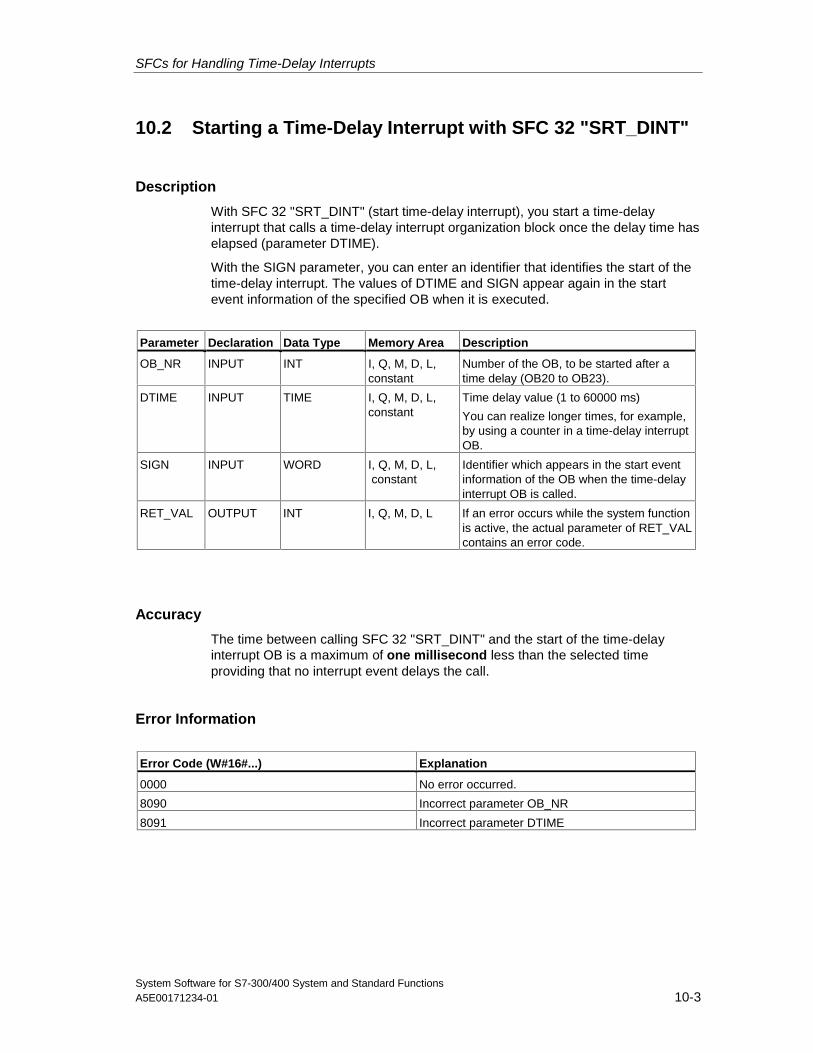
SFCs for Handling Time-Delay Interrupts
System Software for S7-300/400 System and Standard FunctionsA5E00171234-01 10-3
10.2 Starting a Time-Delay Interrupt with SFC 32 "SRT_DINT"
Description
With SFC 32 "SRT_DINT" (start time-delay interrupt), you start a time-delayinterrupt that calls a time-delay interrupt organization block once the delay time haselapsed (parameter DTIME).
With the SIGN parameter, you can enter an identifier that identifies the start of thetime-delay interrupt. The values of DTIME and SIGN appear again in the startevent information of the specified OB when it is executed.
Parameter Declaration Data Type Memory Area Description
OB_NR INPUT INT I, Q, M, D, L,constant
Number of the OB, to be started after atime delay (OB20 to OB23).
DTIME INPUT TIME I, Q, M, D, L,constant
Time delay value (1 to 60000 ms)
You can realize longer times, for example,by using a counter in a time-delay interruptOB.
SIGN INPUT WORD I, Q, M, D, L, constant
Identifier which appears in the start eventinformation of the OB when the time-delayinterrupt OB is called.
RET_VAL OUTPUT INT I, Q, M, D, L If an error occurs while the system functionis active, the actual parameter of RET_VALcontains an error code.
Accuracy
The time between calling SFC 32 "SRT_DINT" and the start of the time-delayinterrupt OB is a maximum of one millisecond less than the selected timeproviding that no interrupt event delays the call.
Error Information
Error Code (W#16#...) Explanation
0000 No error occurred.
8090 Incorrect parameter OB_NR
8091 Incorrect parameter DTIME
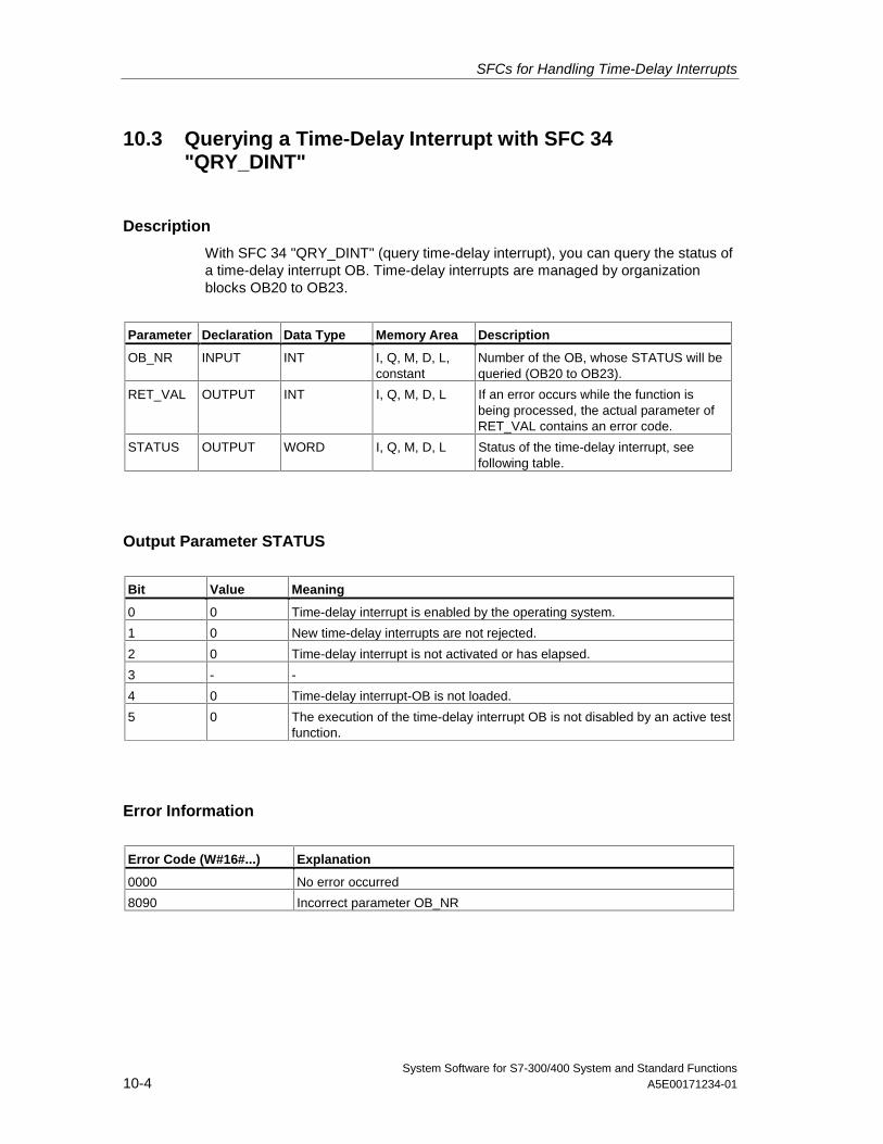
SFCs for Handling Time-Delay Interrupts
System Software for S7-300/400 System and Standard Functions10-4 A5E00171234-01
10.3 Querying a Time-Delay Interrupt with SFC 34"QRY_DINT"
Description
With SFC 34 "QRY_DINT" (query time-delay interrupt), you can query the status ofa time-delay interrupt OB. Time-delay interrupts are managed by organizationblocks OB20 to OB23.
Parameter Declaration Data Type Memory Area Description
OB_NR INPUT INT I, Q, M, D, L,constant
Number of the OB, whose STATUS will bequeried (OB20 to OB23).
RET_VAL OUTPUT INT I, Q, M, D, L If an error occurs while the function isbeing processed, the actual parameter ofRET_VAL contains an error code.
STATUS OUTPUT WORD I, Q, M, D, L Status of the time-delay interrupt, seefollowing table.
Output Parameter STATUS
Bit Value Meaning
0 0 Time-delay interrupt is enabled by the operating system.
1 0 New time-delay interrupts are not rejected.
2 0 Time-delay interrupt is not activated or has elapsed.
3 - -
4 0 Time-delay interrupt-OB is not loaded.
5 0 The execution of the time-delay interrupt OB is not disabled by an active testfunction.
Error Information
Error Code (W#16#...) Explanation
0000 No error occurred
8090 Incorrect parameter OB_NR
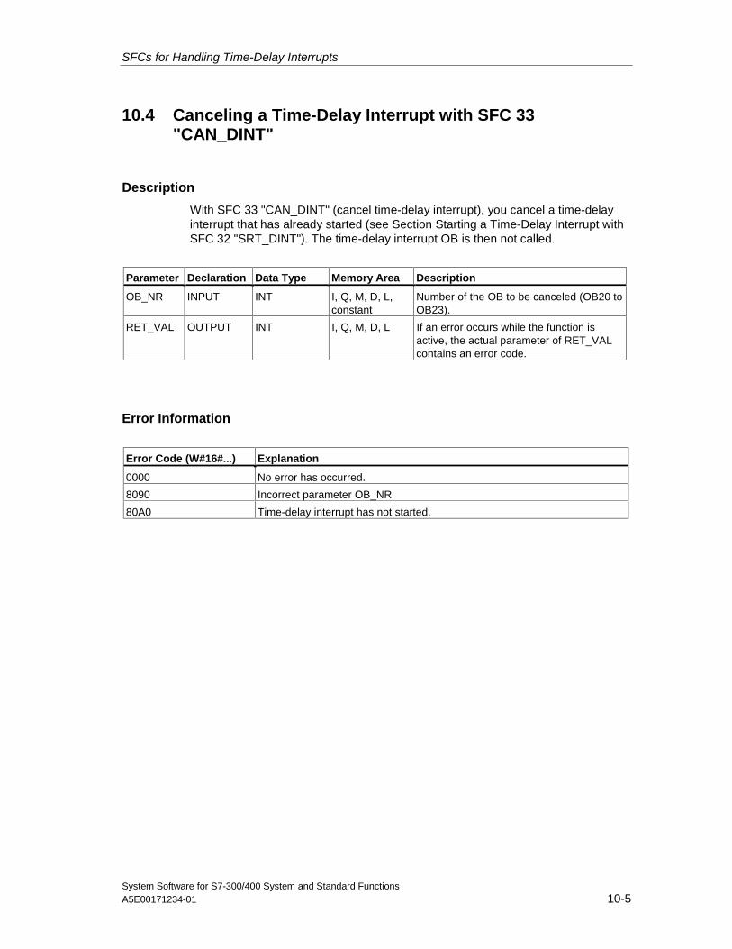
SFCs for Handling Time-Delay Interrupts
System Software for S7-300/400 System and Standard FunctionsA5E00171234-01 10-5
10.4 Canceling a Time-Delay Interrupt with SFC 33"CAN_DINT"
Description
With SFC 33 "CAN_DINT" (cancel time-delay interrupt), you cancel a time-delayinterrupt that has already started (see Section Starting a Time-Delay Interrupt withSFC 32 "SRT_DINT"). The time-delay interrupt OB is then not called.
Parameter Declaration Data Type Memory Area Description
OB_NR INPUT INT I, Q, M, D, L,constant
Number of the OB to be canceled (OB20 toOB23).
RET_VAL OUTPUT INT I, Q, M, D, L If an error occurs while the function isactive, the actual parameter of RET_VALcontains an error code.
Error Information
Error Code (W#16#...) Explanation
0000 No error has occurred.
8090 Incorrect parameter OB_NR
80A0 Time-delay interrupt has not started.

SFCs for Handling Time-Delay Interrupts
System Software for S7-300/400 System and Standard Functions10-6 A5E00171234-01
System Software for S7-300/400 System and Standard FunctionsA5E00171234-01 11-1
11 SFCs for Handling Synchronous Errors
11.1 Masking Synchronous Errors
Introduction
Synchronous errors are programming and access errors. Such errors occur as aresult of programming with incorrect address areas, numbers, or incorrectaddresses. Masking these synchronous errors means the following:
• Masked synchronous errors do not trigger an error OB call and do not lead to aprogrammed alternative reaction.
• The CPU "records" the masked errors that have occurred in an error register.
Masking is carried out by calling the SFC 36 "MSK_FLT".
Unmasking errors means canceling a previously set mask and clearing thecorresponding bit in the event status register of the current priority class. Maskingis canceled as follows:
• By calling SFC 37 "DMSK_FLT"
• When the current priority class has been completed.
If an error occurs after it has been unmasked, the operating system starts thecorresponding error OB. You can program OB121 for a reaction to programmingerrors and OB122 for a reaction to access errors.
You can use SFC 38 "READ_ERR" to read out the masked errors that haveoccurred.
Note: With the S7-300 (except CPU 318), regardless of whether an error is maskedor unmasked, the error is entered in the diagnostic buffer and the group error LEDof the CPU is lit.
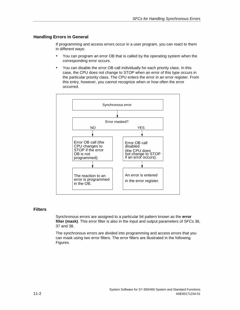
SFCs for Handling Synchronous Errors
System Software for S7-300/400 System and Standard Functions11-2 A5E00171234-01
Handling Errors in General
If programming and access errors occur in a user program, you can react to themin different ways:
• You can program an error OB that is called by the operating system when thecorresponding error occurs.
• You can disable the error OB call individually for each priority class. In thiscase, the CPU does not change to STOP when an error of this type occurs inthe particular priority class. The CPU enters the error in an error register. Fromthis entry, however, you cannot recognize when or how often the erroroccurred.
Error masked?
Synchronous error
NO YES
The reaction to anerror is programmedin the OB.
An error is entered
in the error register.
Error OB call (theCPU changes toSTOP if the errorOB is notprogrammed).
Error OB call
(the CPU doesnot change to STOPif an error occurs).
disabled
Filters
Synchronous errors are assigned to a particular bit pattern known as the errorfilter (mask). This error filter is also in the input and output parameters of SFCs 36,37 and 38.
The synchronous errors are divided into programming and access errors that youcan mask using two error filters. The error filters are illustrated in the followingFigures.
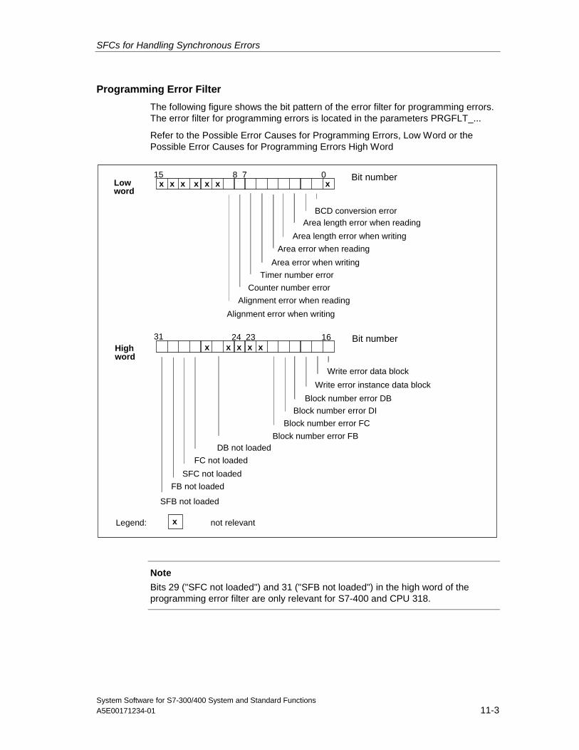
SFCs for Handling Synchronous Errors
System Software for S7-300/400 System and Standard FunctionsA5E00171234-01 11-3
Programming Error Filter
The following figure shows the bit pattern of the error filter for programming errors.The error filter for programming errors is located in the parameters PRGFLT_...
Refer to the Possible Error Causes for Programming Errors, Low Word or thePossible Error Causes for Programming Errors High Word
7 0x
15 8xxxxxx
23 16
DB not loaded
x31 24
FC not loaded
FB not loaded
xxx x
x
SFC not loaded
SFB not loaded
Lowword
Highword
Legend: not relevant
Bit number
BCD conversion error
Area length error when writing
Area length error when reading
Area error when reading
Timer number error
Counter number error
Area error when writing
Alignment error when reading
Alignment error when writing
Bit number
Write error data block
Block number error DB
Write error instance data block
Block number error DI
Block number error FB
Block number error FC
Note
Bits 29 ("SFC not loaded") and 31 ("SFB not loaded") in the high word of theprogramming error filter are only relevant for S7-400 and CPU 318.
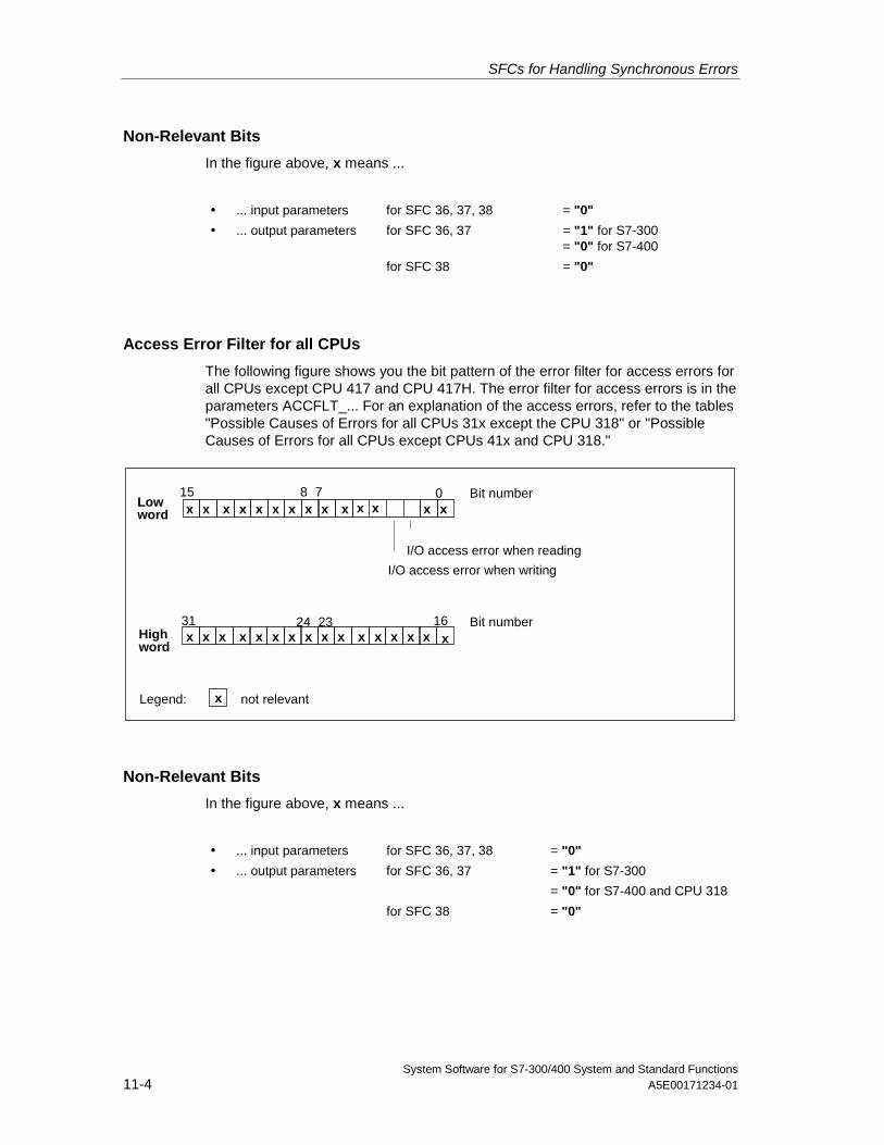
SFCs for Handling Synchronous Errors
System Software for S7-300/400 System and Standard Functions11-4 A5E00171234-01
Non-Relevant Bits
In the figure above, x means ...
• ... input parameters for SFC 36, 37, 38 = "0"
• ... output parameters for SFC 36, 37 = "1" for S7-300= "0" for S7-400
for SFC 38 = "0"
Access Error Filter for all CPUs
The following figure shows you the bit pattern of the error filter for access errors forall CPUs except CPU 417 and CPU 417H. The error filter for access errors is in theparameters ACCFLT_... For an explanation of the access errors, refer to the tables"Possible Causes of Errors for all CPUs 31x except the CPU 318" or "PossibleCauses of Errors for all CPUs except CPUs 41x and CPU 318."
x
7 015 8
23 16xxxxxx xx
31 24x
x
xxx xx x
xxxxxxx xx x x x
I/O access error when reading
I/O access error when writing
Lowword
Highword
Legend: not relevant
Bit number
Bit number
x x
Non-Relevant Bits
In the figure above, x means ...
• ... input parameters for SFC 36, 37, 38 = "0"
• ... output parameters for SFC 36, 37 = "1" for S7-300
= "0" for S7-400 and CPU 318
for SFC 38 = "0"
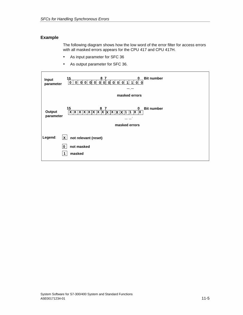
SFCs for Handling Synchronous Errors
System Software for S7-300/400 System and Standard FunctionsA5E00171234-01 11-5
Example
The following diagram shows how the low word of the error filter for access errorswith all masked errors appears for the CPU 417 and CPU 417H.
• As input parameter for SFC 36
• As output parameter for SFC 36.
Inputparameter
7 0 Bit number
masked errors
015 8
000000
Outputparameter
7 0 Bit number15 8
00000
XXXXX XX X X X X11X XX
0 0 1 1
masked errors
Legend: X
not masked
masked
0
1
not relevant (reset)
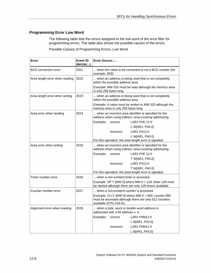
SFCs for Handling Synchronous Errors
System Software for S7-300/400 System and Standard Functions11-6 A5E00171234-01
Programming Error Low Word
The following table lists the errors assigned to the low word of the error filter forprogramming errors. The table also shows the possible causes of the errors.
Possible Causes of Programming Errors, Low Word
Error Event ID(W#16#...)
Error Occurs ...
BCD conversion error 2521 ... when the value to be converted is not a BCD number (forexample, 5E8)
Area length error when reading 2522 ... when an address is being used that is not completelywithin the possible address area.
Example: MW 320 must be read although the memory areais only 256 bytes long.
Area length error when writing 2523 ... when an address is being used that is not completelywithin the possible address area.
Example: A value must be written to MW 320 although thememory area is only 256 bytes long.
Area error when reading 2524 ... when an incorrect area identifier is specified for theaddress when using indirect, area-crossing addressing.
Example: correct: LAR1 P#E 12.0
L W[AR1, P#0.0]
incorrect: LAR1 P#12.0
L W[AR1, P#0.0]For this operation, the area length error is signaled.
Area error when writing 2525 ... when an incorrect area identifier is specified for theaddress when using indirect, area-crossing addressing.
Example: correct: LAR1 P#E 12.0
T W[AR1, P#0.0]
incorrect: LAR1 P#12.0
T W[AR1, P#0.0]For this operation, the area length error is signaled.
Timer number error 2526 ... when a non-existent timer is accessed.
Example: SP T [MW 0] where MW 0 = 129; timer 129 mustbe started although there are only 128 timers available.
Counter number error 2527 ... when a non-existent counter is accessed.
Example: CU C [MW 0] where MW 0 = 600; counter 600must be accessed although there are only 512 countersavailable (CPU 416-D).
Alignment error when reading 2528 ... when a byte, word or double word address isaddressed with a bit address ≠ 0.
Example: correct: LAR1 P#M12.0
L B[AR1, P#0.0]
incorrect: LAR1 P#M12.4
L B[AR1, P#0.0]
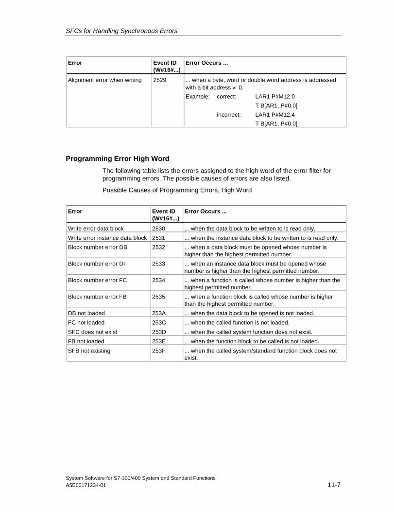
SFCs for Handling Synchronous Errors
System Software for S7-300/400 System and Standard FunctionsA5E00171234-01 11-7
Error Event ID(W#16#...)
Error Occurs ...
Alignment error when writing 2529 ... when a byte, word or double word address is addressedwith a bit address ≠ 0.
Example: correct: LAR1 P#M12.0
T B[AR1, P#0.0]
incorrect: LAR1 P#M12.4
T B[AR1, P#0.0]
Programming Error High Word
The following table lists the errors assigned to the high word of the error filter forprogramming errors. The possible causes of errors are also listed.
Possible Causes of Programming Errors, High Word
Error Event ID(W#16#...)
Error Occurs ...
Write error data block 2530 ... when the data block to be written to is read only.
Write error instance data block 2531 ... when the instance data block to be written to is read only.
Block number error DB 2532 ... when a data block must be opened whose number ishigher than the highest permitted number.
Block number error DI 2533 ... when an instance data block must be opened whosenumber is higher than the highest permitted number.
Block number error FC 2534 ... when a function is called whose number is higher than thehighest permitted number.
Block number error FB 2535 ... when a function block is called whose number is higherthan the highest permitted number.
DB not loaded 253A ... when the data block to be opened is not loaded.
FC not loaded 253C ... when the called function is not loaded.
SFC does not exist 253D ... when the called system function does not exist.
FB not loaded 253E ... when the function block to be called is not loaded.
SFB not existing 253F ... when the called system/standard function block does notexist.
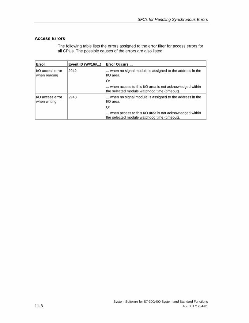
SFCs for Handling Synchronous Errors
System Software for S7-300/400 System and Standard Functions11-8 A5E00171234-01
Access Errors
The following table lists the errors assigned to the error filter for access errors forall CPUs. The possible causes of the errors are also listed.
Error Event ID (W#16#...) Error Occurs ...
I/O access errorwhen reading
2942 ... when no signal module is assigned to the address in theI/O area.
Or
... when access to this I/O area is not acknowledged withinthe selected module watchdog time (timeout).
I/O access errorwhen writing
2943 ... when no signal module is assigned to the address in theI/O area.
Or
... when access to this I/O area is not acknowledged withinthe selected module watchdog time (timeout).
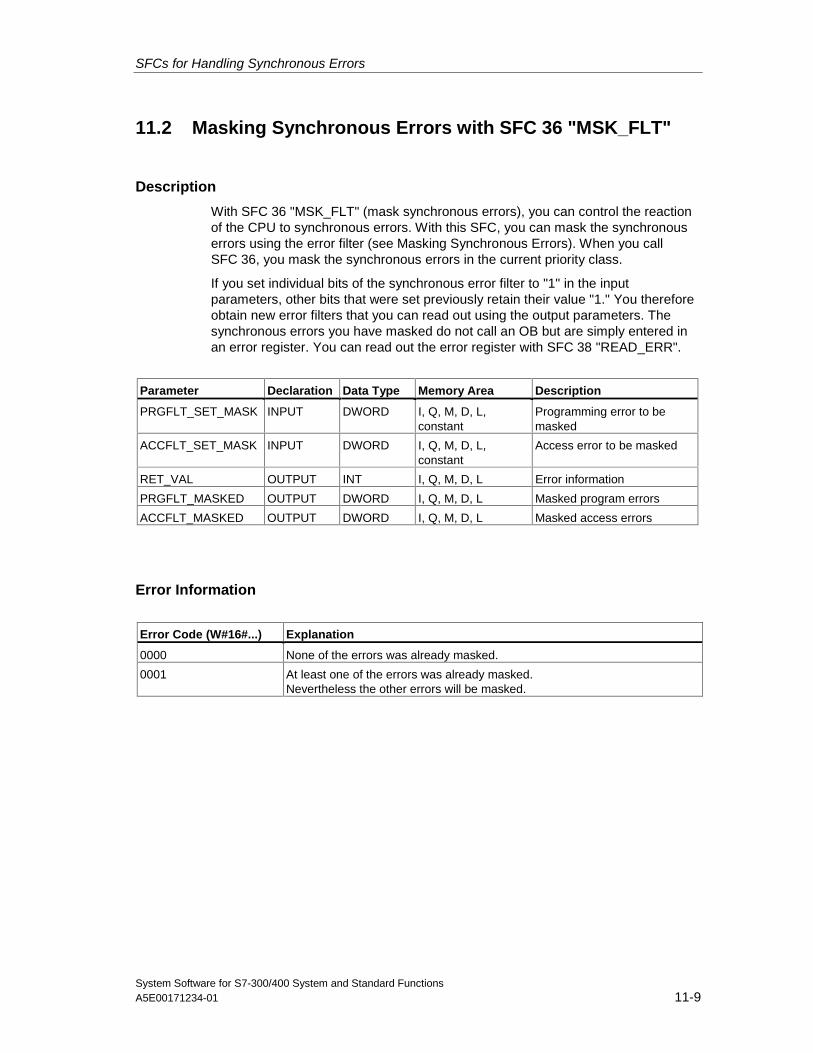
SFCs for Handling Synchronous Errors
System Software for S7-300/400 System and Standard FunctionsA5E00171234-01 11-9
11.2 Masking Synchronous Errors with SFC 36 "MSK_FLT"
Description
With SFC 36 "MSK_FLT" (mask synchronous errors), you can control the reactionof the CPU to synchronous errors. With this SFC, you can mask the synchronouserrors using the error filter (see Masking Synchronous Errors). When you callSFC 36, you mask the synchronous errors in the current priority class.
If you set individual bits of the synchronous error filter to "1" in the inputparameters, other bits that were set previously retain their value "1." You thereforeobtain new error filters that you can read out using the output parameters. Thesynchronous errors you have masked do not call an OB but are simply entered inan error register. You can read out the error register with SFC 38 "READ_ERR".
Parameter Declaration Data Type Memory Area Description
PRGFLT_SET_MASK INPUT DWORD I, Q, M, D, L,constant
Programming error to bemasked
ACCFLT_SET_MASK INPUT DWORD I, Q, M, D, L,constant
Access error to be masked
RET_VAL OUTPUT INT I, Q, M, D, L Error information
PRGFLT_MASKED OUTPUT DWORD I, Q, M, D, L Masked program errors
ACCFLT_MASKED OUTPUT DWORD I, Q, M, D, L Masked access errors
Error Information
Error Code (W#16#...) Explanation
0000 None of the errors was already masked.
0001 At least one of the errors was already masked.Nevertheless the other errors will be masked.
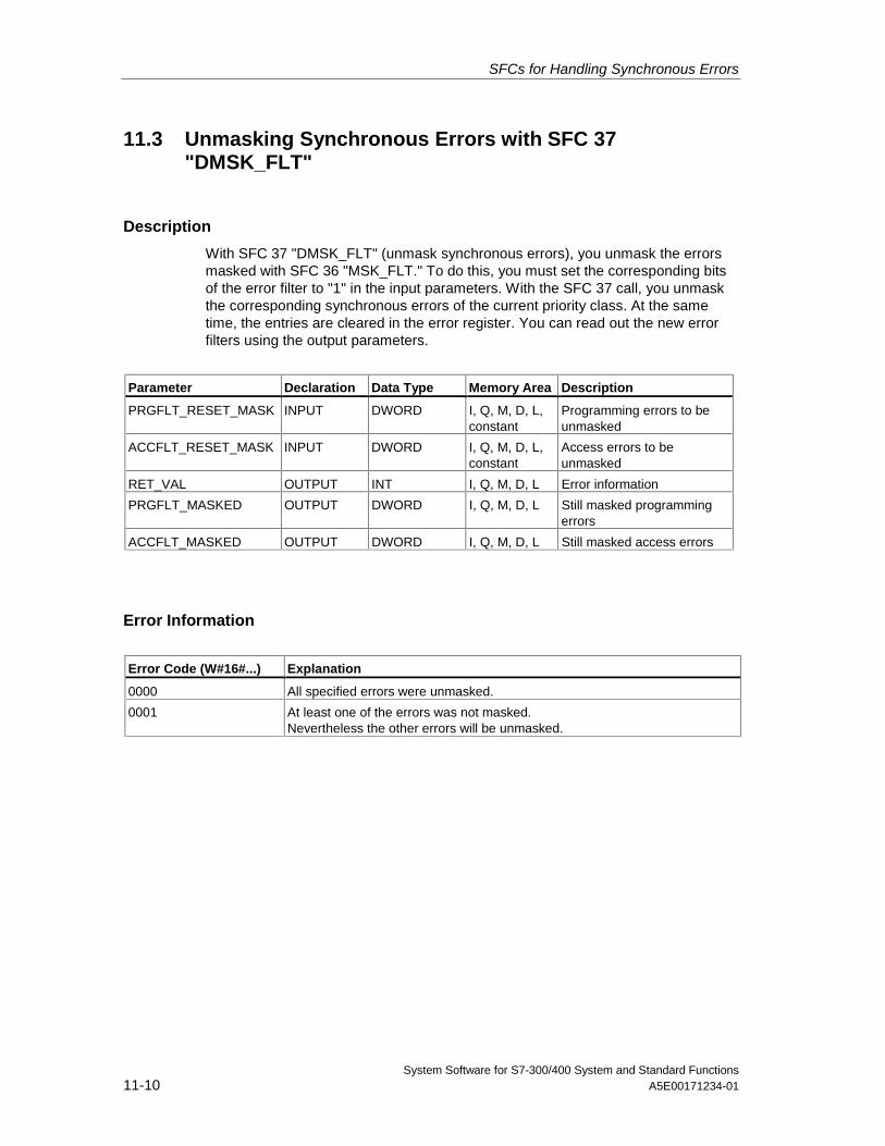
SFCs for Handling Synchronous Errors
System Software for S7-300/400 System and Standard Functions11-10 A5E00171234-01
11.3 Unmasking Synchronous Errors with SFC 37"DMSK_FLT"
Description
With SFC 37 "DMSK_FLT" (unmask synchronous errors), you unmask the errorsmasked with SFC 36 "MSK_FLT." To do this, you must set the corresponding bitsof the error filter to "1" in the input parameters. With the SFC 37 call, you unmaskthe corresponding synchronous errors of the current priority class. At the sametime, the entries are cleared in the error register. You can read out the new errorfilters using the output parameters.
Parameter Declaration Data Type Memory Area Description
PRGFLT_RESET_MASK INPUT DWORD I, Q, M, D, L,constant
Programming errors to beunmasked
ACCFLT_RESET_MASK INPUT DWORD I, Q, M, D, L,constant
Access errors to beunmasked
RET_VAL OUTPUT INT I, Q, M, D, L Error information
PRGFLT_MASKED OUTPUT DWORD I, Q, M, D, L Still masked programmingerrors
ACCFLT_MASKED OUTPUT DWORD I, Q, M, D, L Still masked access errors
Error Information
Error Code (W#16#...) Explanation
0000 All specified errors were unmasked.
0001 At least one of the errors was not masked.Nevertheless the other errors will be unmasked.
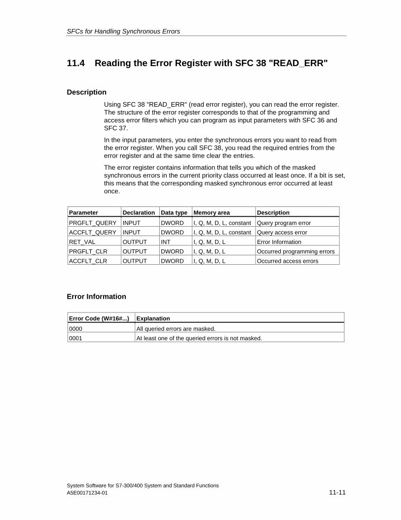
SFCs for Handling Synchronous Errors
System Software for S7-300/400 System and Standard FunctionsA5E00171234-01 11-11
11.4 Reading the Error Register with SFC 38 "READ_ERR"
Description
Using SFC 38 "READ_ERR" (read error register), you can read the error register.The structure of the error register corresponds to that of the programming andaccess error filters which you can program as input parameters with SFC 36 andSFC 37.
In the input parameters, you enter the synchronous errors you want to read fromthe error register. When you call SFC 38, you read the required entries from theerror register and at the same time clear the entries.
The error register contains information that tells you which of the maskedsynchronous errors in the current priority class occurred at least once. If a bit is set,this means that the corresponding masked synchronous error occurred at leastonce.
Parameter Declaration Data type Memory area Description
PRGFLT_QUERY INPUT DWORD I, Q, M, D, L, constant Query program error
ACCFLT_QUERY INPUT DWORD I, Q, M, D, L, constant Query access error
RET_VAL OUTPUT INT I, Q, M, D, L Error Information
PRGFLT_CLR OUTPUT DWORD I, Q, M, D, L Occurred programming errors
ACCFLT_CLR OUTPUT DWORD I, Q, M, D, L Occurred access errors
Error Information
Error Code (W#16#...) Explanation
0000 All queried errors are masked.
0001 At least one of the queried errors is not masked.

SFCs for Handling Synchronous Errors
System Software for S7-300/400 System and Standard Functions11-12 A5E00171234-01
System Software for S7-300/400 System and Standard FunctionsA5E00171234-01 12-1
12 SFCs for Handling Interrupts andAsynchronous Errors
12.1 Delaying and Disabling Interrupt and AsynchronousErrors
Purpose of SFC 39 to SFC 42
With these SFCs, you can achieve the following:
• Disable interrupts and asynchronous errors with SFC 39 "DIS_IRT" for allsubsequent CPU cycles.
• Delay higher priority classes with SFC 41 "DIS_AIRT" until the end of the OB.
• Enable interrupts and asynchronous errors with SFC 40 "EN_IRT" or SFC 42"EN_AIRT."
You program the handling of interrupts and asynchronous errors in the userprogram. You must also program the corresponding OBs.
Advantage of SFC 41 and SFC 42
Delaying higher priority interrupts and asynchronous errors by disabling them withSFC 41 "DIS_AIRT" and then enabling them again with SFC 42 "EN_AIRT" has thefollowing advantages:
The number of interrupts delayed is counted by the CPU. If you have delayedinterrupts and asynchronous errors, the delay cannot be canceled by standard FCcalls if the interrupts and asynchronous errors are also disabled and then enabledagain in the standard FCs themselves.
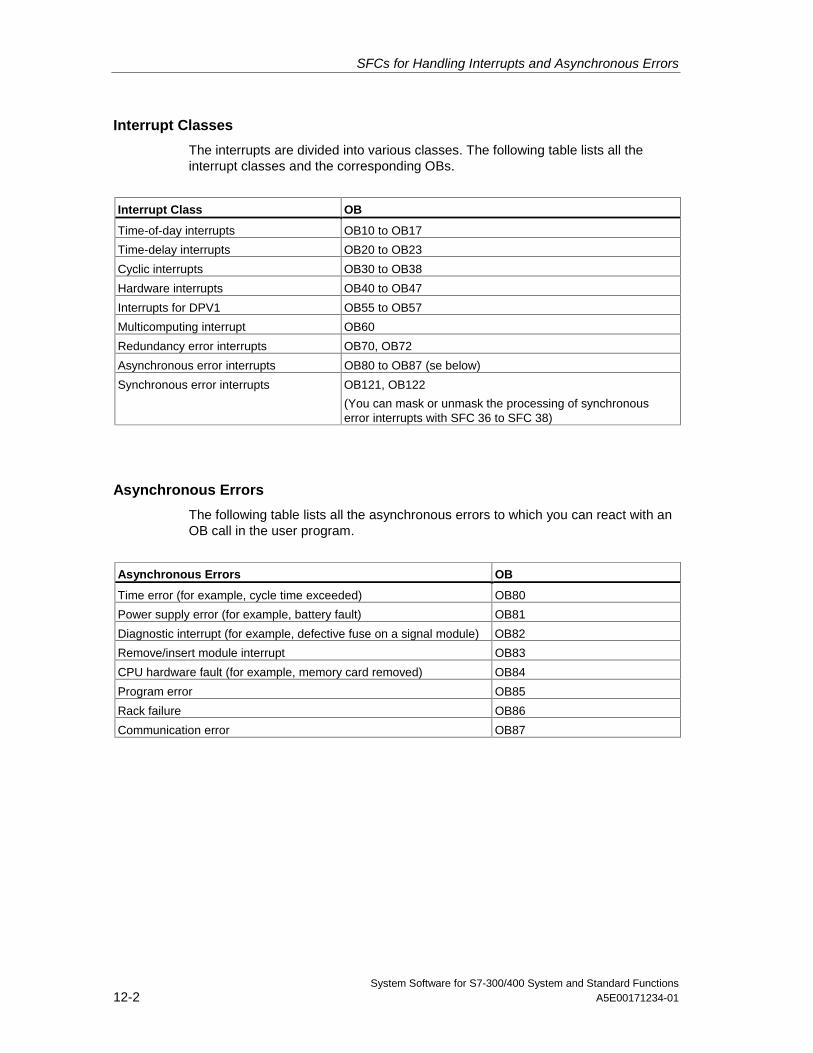
SFCs for Handling Interrupts and Asynchronous Errors
System Software for S7-300/400 System and Standard Functions12-2 A5E00171234-01
Interrupt Classes
The interrupts are divided into various classes. The following table lists all theinterrupt classes and the corresponding OBs.
Interrupt Class OB
Time-of-day interrupts OB10 to OB17
Time-delay interrupts OB20 to OB23
Cyclic interrupts OB30 to OB38
Hardware interrupts OB40 to OB47
Interrupts for DPV1 OB55 to OB57
Multicomputing interrupt OB60
Redundancy error interrupts OB70, OB72
Asynchronous error interrupts OB80 to OB87 (se below)
Synchronous error interrupts OB121, OB122
(You can mask or unmask the processing of synchronouserror interrupts with SFC 36 to SFC 38)
Asynchronous Errors
The following table lists all the asynchronous errors to which you can react with anOB call in the user program.
Asynchronous Errors OB
Time error (for example, cycle time exceeded) OB80
Power supply error (for example, battery fault) OB81
Diagnostic interrupt (for example, defective fuse on a signal module) OB82
Remove/insert module interrupt OB83
CPU hardware fault (for example, memory card removed) OB84
Program error OB85
Rack failure OB86
Communication error OB87
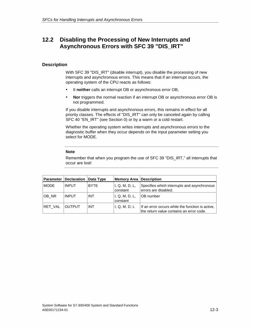
SFCs for Handling Interrupts and Asynchronous Errors
System Software for S7-300/400 System and Standard FunctionsA5E00171234-01 12-3
12.2 Disabling the Processing of New Interrupts andAsynchronous Errors with SFC 39 "DIS_IRT"
Description
With SFC 39 "DIS_IRT" (disable interrupt), you disable the processing of newinterrupts and asynchronous errors. This means that if an interrupt occurs, theoperating system of the CPU reacts as follows:
• It neither calls an interrupt OB or asynchronous error OB,
• Nor triggers the normal reaction if an interrupt OB or asynchronous error OB isnot programmed.
If you disable interrupts and asynchronous errors, this remains in effect for allpriority classes. The effects of "DIS_IRT" can only be canceled again by callingSFC 40 "EN_IRT" (see Section 0) or by a warm or a cold restart.
Whether the operating system writes interrupts and asynchronous errors to thediagnostic buffer when they occur depends on the input parameter setting youselect for MODE.
Note
Remember that when you program the use of SFC 39 "DIS_IRT," all interrupts thatoccur are lost!
Parameter Declaration Data Type Memory Area Description
MODE INPUT BYTE I, Q, M, D, L,constant
Specifies which interrupts and asynchronouserrors are disabled.
OB_NR INPUT INT I, Q, M, D, L,constant
OB number
RET_VAL OUTPUT INT I, Q, M, D, L If an error occurs while the function is active,the return value contains an error code.
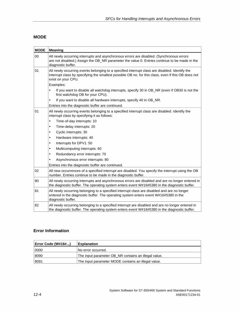
SFCs for Handling Interrupts and Asynchronous Errors
System Software for S7-300/400 System and Standard Functions12-4 A5E00171234-01
MODE
MODE Meaning
00 All newly occurring interrupts and asynchronous errors are disabled. (Synchronous errorsare not disabled.) Assign the OB_NR parameter the value 0. Entries continue to be made in thediagnostic buffer.
01 All newly occurring events belonging to a specified interrupt class are disabled. Identify theinterrupt class by specifying the smallest possible OB no. for this class, even if this OB does notexist on your CPU.
Examples:
• If you want to disable all watchdog interrupts, specify 30 in OB_NR (even if OB30 is not thefirst watchdog OB for your CPU).
• If you want to disable all hardware interrupts, specify 40 in OB_NR.
Entries into the diagnostic buffer are continued.
01 All newly occurring events belonging to a specified interrupt class are disabled. Identify theinterrupt class by specifying it as follows:
• Time-of-day interrupts: 10
• Time-delay interrupts: 20
• Cyclic interrupts: 30
• Hardware interrupts: 40
• Interrupts for DPV1: 50
• Multicomputing interrupts: 60
• Redundancy error interrupts: 70
• Asynchronous error interrupts: 80
Entries into the diagnostic buffer are continued.
02 All new occurrences of a specified interrupt are disabled. You specify the interrupt using the OBnumber. Entries continue to be made in the diagnostic buffer.
80 All newly occurring interrupts and asynchronous errors are disabled and are no longer entered inthe diagnostic buffer. The operating system enters event W#16#5380 in the diagnostic buffer.
81 All newly occurring belonging to a specified interrupt class are disabled and are no longerentered in the diagnostic buffer. The operating system enters event W#16#5380 in thediagnostic buffer.
82 All newly occurring belonging to a specified interrupt are disabled and are no longer entered inthe diagnostic buffer. The operating system enters event W#16#5380 in the diagnostic buffer.
Error Information
Error Code (W#16#...) Explanation
0000 No error occurred.
8090 The input parameter OB_NR contains an illegal value.
8091 The input parameter MODE contains an illegal value.
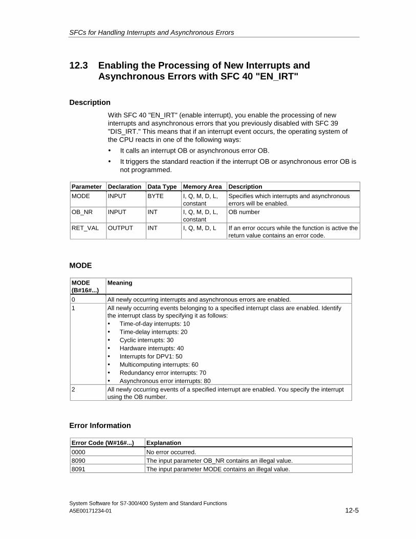
SFCs for Handling Interrupts and Asynchronous Errors
System Software for S7-300/400 System and Standard FunctionsA5E00171234-01 12-5
12.3 Enabling the Processing of New Interrupts andAsynchronous Errors with SFC 40 "EN_IRT"
Description
With SFC 40 "EN_IRT" (enable interrupt), you enable the processing of newinterrupts and asynchronous errors that you previously disabled with SFC 39"DIS_IRT." This means that if an interrupt event occurs, the operating system ofthe CPU reacts in one of the following ways:
• It calls an interrupt OB or asynchronous error OB.
• It triggers the standard reaction if the interrupt OB or asynchronous error OB isnot programmed.
Parameter Declaration Data Type Memory Area Description
MODE INPUT BYTE I, Q, M, D, L,constant
Specifies which interrupts and asynchronouserrors will be enabled.
OB_NR INPUT INT I, Q, M, D, L,constant
OB number
RET_VAL OUTPUT INT I, Q, M, D, L If an error occurs while the function is active thereturn value contains an error code.
MODE
MODE(B#16#...)
Meaning
0 All newly occurring interrupts and asynchronous errors are enabled.1 All newly occurring events belonging to a specified interrupt class are enabled. Identify
the interrupt class by specifying it as follows:• Time-of-day interrupts: 10• Time-delay interrupts: 20• Cyclic interrupts: 30• Hardware interrupts: 40• Interrupts for DPV1: 50• Multicomputing interrupts: 60• Redundancy error interrupts: 70• Asynchronous error interrupts: 80
2 All newly occurring events of a specified interrupt are enabled. You specify the interruptusing the OB number.
Error Information
Error Code (W#16#...) Explanation
0000 No error occurred.8090 The input parameter OB_NR contains an illegal value.8091 The input parameter MODE contains an illegal value.
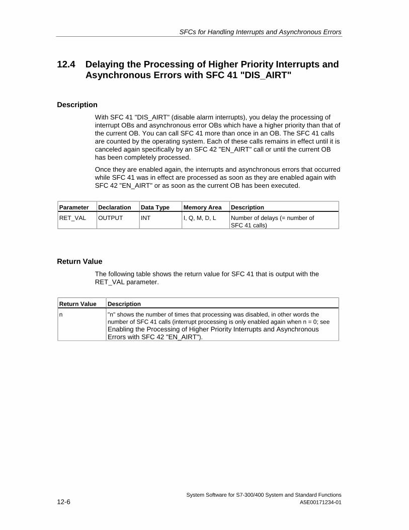
SFCs for Handling Interrupts and Asynchronous Errors
System Software for S7-300/400 System and Standard Functions12-6 A5E00171234-01
12.4 Delaying the Processing of Higher Priority Interrupts andAsynchronous Errors with SFC 41 "DIS_AIRT"
Description
With SFC 41 "DIS_AIRT" (disable alarm interrupts), you delay the processing ofinterrupt OBs and asynchronous error OBs which have a higher priority than that ofthe current OB. You can call SFC 41 more than once in an OB. The SFC 41 callsare counted by the operating system. Each of these calls remains in effect until it iscanceled again specifically by an SFC 42 "EN_AIRT" call or until the current OBhas been completely processed.
Once they are enabled again, the interrupts and asynchronous errors that occurredwhile SFC 41 was in effect are processed as soon as they are enabled again withSFC 42 "EN_AIRT" or as soon as the current OB has been executed.
Parameter Declaration Data Type Memory Area Description
RET_VAL OUTPUT INT I, Q, M, D, L Number of delays (= number ofSFC 41 calls)
Return Value
The following table shows the return value for SFC 41 that is output with theRET_VAL parameter.
Return Value Description
n "n" shows the number of times that processing was disabled, in other words thenumber of SFC 41 calls (interrupt processing is only enabled again when n = 0; seeEnabling the Processing of Higher Priority Interrupts and AsynchronousErrors with SFC 42 "EN_AIRT").
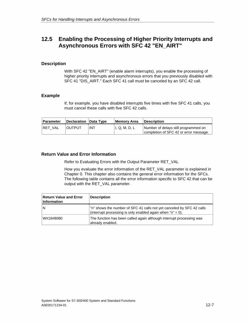
SFCs for Handling Interrupts and Asynchronous Errors
System Software for S7-300/400 System and Standard FunctionsA5E00171234-01 12-7
12.5 Enabling the Processing of Higher Priority Interrupts andAsynchronous Errors with SFC 42 "EN_AIRT"
Description
With SFC 42 "EN_AIRT" (enable alarm interrupts), you enable the processing ofhigher priority interrupts and asynchronous errors that you previously disabled withSFC 41 "DIS_AIRT." Each SFC 41 call must be canceled by an SFC 42 call.
Example
If, for example, you have disabled interrupts five times with five SFC 41 calls, youmust cancel these calls with five SFC 42 calls.
Parameter Declaration Data Type Memory Area Description
RET_VAL OUTPUT INT I, Q, M, D, L Number of delays still programmed oncompletion of SFC 42 or error message.
Return Value and Error Information
Refer to Evaluating Errors with the Output Parameter RET_VAL
How you evaluate the error information of the RET_VAL parameter is explained inChapter 0. This chapter also contains the general error information for the SFCs.The following table contains all the error information specific to SFC 42 that can beoutput with the RET_VAL parameter.
Return Value and ErrorInformation
Description
N "n" shows the number of SFC 41 calls not yet canceled by SFC 42 calls(interrupt processing is only enabled again when "n" = 0).
W#16#8080 The function has been called again although interrupt processing wasalready enabled.

SFCs for Handling Interrupts and Asynchronous Errors
System Software for S7-300/400 System and Standard Functions12-8 A5E00171234-01
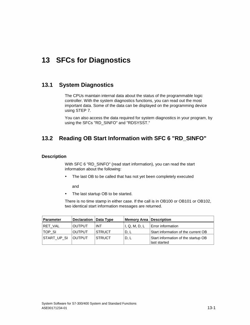
System Software for S7-300/400 System and Standard FunctionsA5E00171234-01 13-1
13 SFCs for Diagnostics
13.1 System Diagnostics
The CPUs maintain internal data about the status of the programmable logiccontroller. With the system diagnostics functions, you can read out the mostimportant data. Some of the data can be displayed on the programming deviceusing STEP 7.
You can also access the data required for system diagnostics in your program, byusing the SFCs "RD_SINFO" and "RDSYSST."
13.2 Reading OB Start Information with SFC 6 "RD_SINFO"
Description
With SFC 6 "RD_SINFO" (read start information), you can read the startinformation about the following:
• The last OB to be called that has not yet been completely executed
and
• The last startup OB to be started.
There is no time stamp in either case. If the call is in OB100 or OB101 or OB102,two identical start information messages are returned.
Parameter Declaration Data Type Memory Area Description
RET_VAL OUTPUT INT I, Q, M, D, L Error information
TOP_SI OUTPUT STRUCT D, L Start information of the current OB
START_UP_SI OUTPUT STRUCT D, L Start information of the startup OBlast started
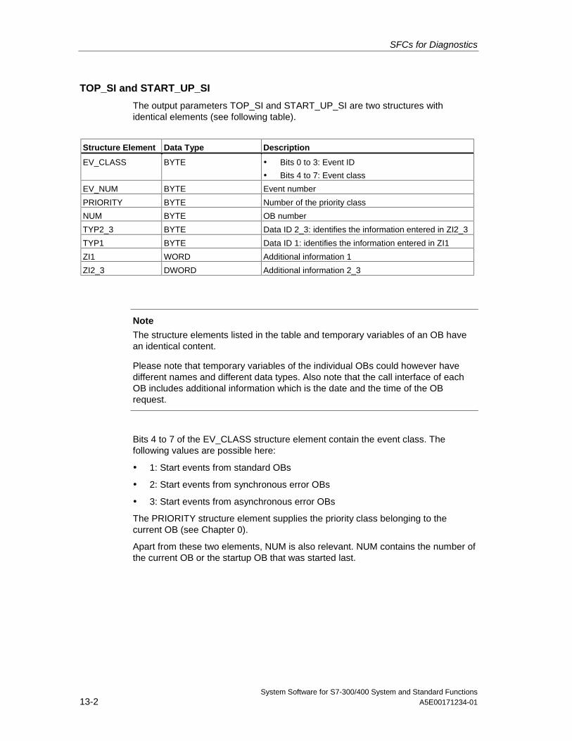
SFCs for Diagnostics
System Software for S7-300/400 System and Standard Functions13-2 A5E00171234-01
TOP_SI and START_UP_SI
The output parameters TOP_SI and START_UP_SI are two structures withidentical elements (see following table).
Structure Element Data Type Description
EV_CLASS BYTE • Bits 0 to 3: Event ID
• Bits 4 to 7: Event class
EV_NUM BYTE Event number
PRIORITY BYTE Number of the priority class
NUM BYTE OB number
TYP2_3 BYTE Data ID 2_3: identifies the information entered in ZI2_3
TYP1 BYTE Data ID 1: identifies the information entered in ZI1
ZI1 WORD Additional information 1
ZI2_3 DWORD Additional information 2_3
Note
The structure elements listed in the table and temporary variables of an OB havean identical content.
Please note that temporary variables of the individual OBs could however havedifferent names and different data types. Also note that the call interface of eachOB includes additional information which is the date and the time of the OBrequest.
Bits 4 to 7 of the EV_CLASS structure element contain the event class. Thefollowing values are possible here:
• 1: Start events from standard OBs
• 2: Start events from synchronous error OBs
• 3: Start events from asynchronous error OBs
The PRIORITY structure element supplies the priority class belonging to thecurrent OB (see Chapter 0).
Apart from these two elements, NUM is also relevant. NUM contains the number ofthe current OB or the startup OB that was started last.
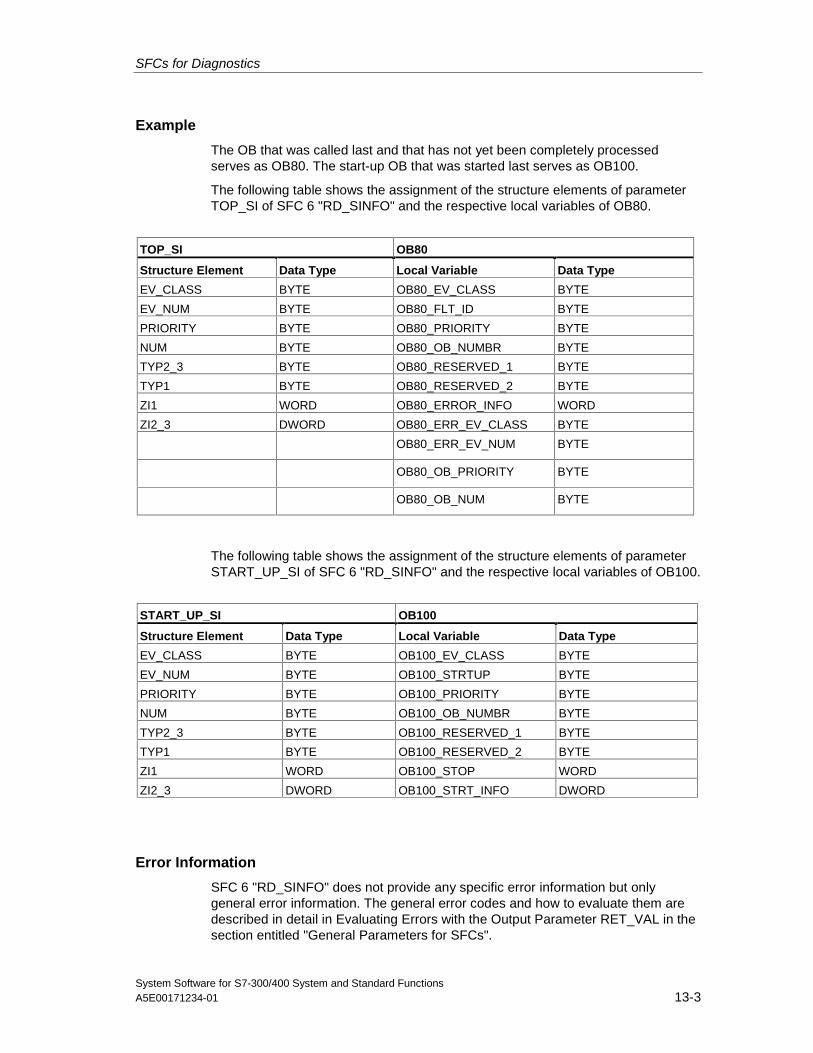
SFCs for Diagnostics
System Software for S7-300/400 System and Standard FunctionsA5E00171234-01 13-3
Example
The OB that was called last and that has not yet been completely processedserves as OB80. The start-up OB that was started last serves as OB100.
The following table shows the assignment of the structure elements of parameterTOP_SI of SFC 6 "RD_SINFO" and the respective local variables of OB80.
TOP_SI OB80
Structure Element Data Type Local Variable Data Type
EV_CLASS BYTE OB80_EV_CLASS BYTE
EV_NUM BYTE OB80_FLT_ID BYTE
PRIORITY BYTE OB80_PRIORITY BYTE
NUM BYTE OB80_OB_NUMBR BYTE
TYP2_3 BYTE OB80_RESERVED_1 BYTE
TYP1 BYTE OB80_RESERVED_2 BYTE
ZI1 WORD OB80_ERROR_INFO WORD
ZI2_3 DWORD OB80_ERR_EV_CLASS BYTE
OB80_ERR_EV_NUM BYTE
OB80_OB_PRIORITY BYTE
OB80_OB_NUM BYTE
The following table shows the assignment of the structure elements of parameterSTART_UP_SI of SFC 6 "RD_SINFO" and the respective local variables of OB100.
START_UP_SI OB100
Structure Element Data Type Local Variable Data Type
EV_CLASS BYTE OB100_EV_CLASS BYTE
EV_NUM BYTE OB100_STRTUP BYTE
PRIORITY BYTE OB100_PRIORITY BYTE
NUM BYTE OB100_OB_NUMBR BYTE
TYP2_3 BYTE OB100_RESERVED_1 BYTE
TYP1 BYTE OB100_RESERVED_2 BYTE
ZI1 WORD OB100_STOP WORD
ZI2_3 DWORD OB100_STRT_INFO DWORD
Error Information
SFC 6 "RD_SINFO" does not provide any specific error information but onlygeneral error information. The general error codes and how to evaluate them aredescribed in detail in Evaluating Errors with the Output Parameter RET_VAL in thesection entitled "General Parameters for SFCs".
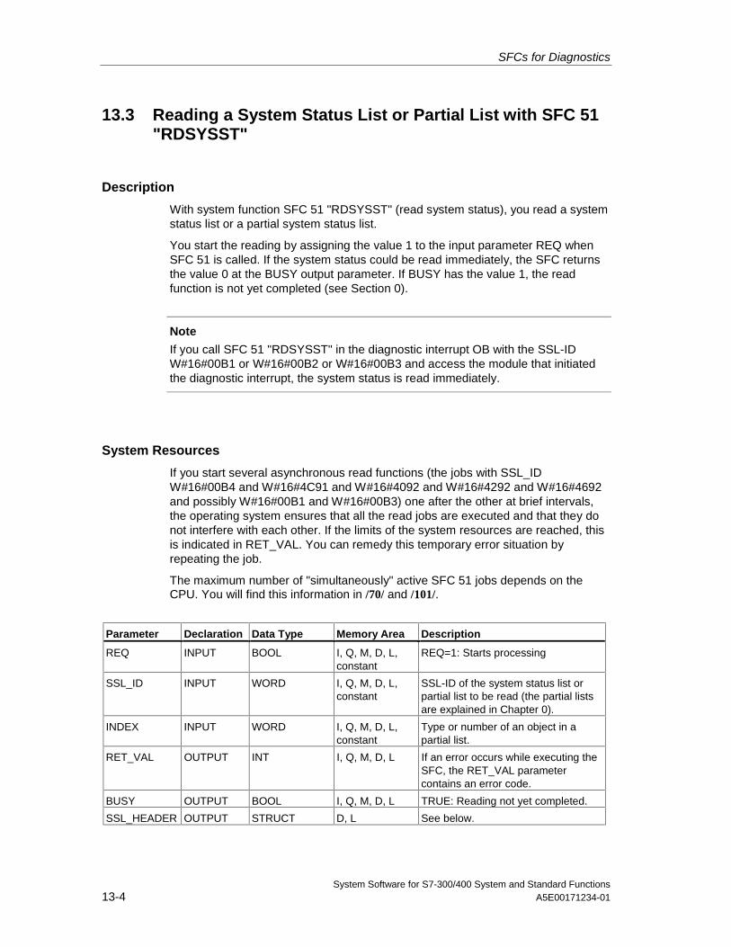
SFCs for Diagnostics
System Software for S7-300/400 System and Standard Functions13-4 A5E00171234-01
13.3 Reading a System Status List or Partial List with SFC 51"RDSYSST"
Description
With system function SFC 51 "RDSYSST" (read system status), you read a systemstatus list or a partial system status list.
You start the reading by assigning the value 1 to the input parameter REQ whenSFC 51 is called. If the system status could be read immediately, the SFC returnsthe value 0 at the BUSY output parameter. If BUSY has the value 1, the readfunction is not yet completed (see Section 0).
Note
If you call SFC 51 "RDSYSST" in the diagnostic interrupt OB with the SSL-IDW#16#00B1 or W#16#00B2 or W#16#00B3 and access the module that initiatedthe diagnostic interrupt, the system status is read immediately.
System Resources
If you start several asynchronous read functions (the jobs with SSL_IDW#16#00B4 and W#16#4C91 and W#16#4092 and W#16#4292 and W#16#4692and possibly W#16#00B1 and W#16#00B3) one after the other at brief intervals,the operating system ensures that all the read jobs are executed and that they donot interfere with each other. If the limits of the system resources are reached, thisis indicated in RET_VAL. You can remedy this temporary error situation byrepeating the job.
The maximum number of "simultaneously" active SFC 51 jobs depends on theCPU. You will find this information in /70/ and /101/.
Parameter Declaration Data Type Memory Area Description
REQ INPUT BOOL I, Q, M, D, L,constant
REQ=1: Starts processing
SSL_ID INPUT WORD I, Q, M, D, L,constant
SSL-ID of the system status list orpartial list to be read (the partial listsare explained in Chapter 0).
INDEX INPUT WORD I, Q, M, D, L,constant
Type or number of an object in apartial list.
RET_VAL OUTPUT INT I, Q, M, D, L If an error occurs while executing theSFC, the RET_VAL parametercontains an error code.
BUSY OUTPUT BOOL I, Q, M, D, L TRUE: Reading not yet completed.
SSL_HEADER OUTPUT STRUCT D, L See below.
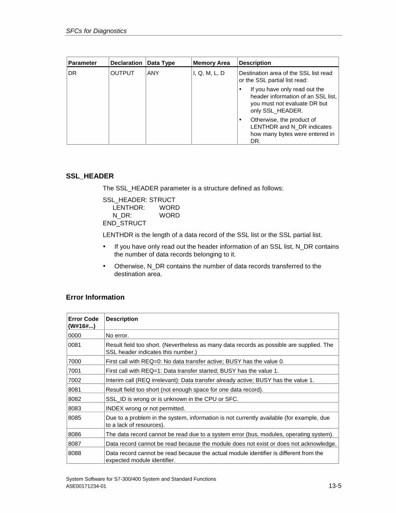
SFCs for Diagnostics
System Software for S7-300/400 System and Standard FunctionsA5E00171234-01 13-5
Parameter Declaration Data Type Memory Area Description
DR OUTPUT ANY I, Q, M, L, D Destination area of the SSL list reador the SSL partial list read:
• If you have only read out theheader information of an SSL list,you must not evaluate DR butonly SSL_HEADER.
• Otherwise, the product ofLENTHDR and N_DR indicateshow many bytes were entered inDR.
SSL_HEADER
The SSL_HEADER parameter is a structure defined as follows:
SSL_HEADER: STRUCTLENTHDR: WORDN_DR: WORD
END_STRUCT
LENTHDR is the length of a data record of the SSL list or the SSL partial list.
• If you have only read out the header information of an SSL list, N_DR containsthe number of data records belonging to it.
• Otherwise, N_DR contains the number of data records transferred to thedestination area.
Error Information
Error Code(W#16#...)
Description
0000 No error.
0081 Result field too short. (Nevertheless as many data records as possible are supplied. TheSSL header indicates this number.)
7000 First call with REQ=0: No data transfer active; BUSY has the value 0.
7001 First call with REQ=1: Data transfer started; BUSY has the value 1.
7002 Interim call (REQ irrelevant): Data transfer already active; BUSY has the value 1.
8081 Result field too short (not enough space for one data record).
8082 SSL_ID is wrong or is unknown in the CPU or SFC.
8083 INDEX wrong or not permitted.
8085 Due to a problem in the system, information is not currently available (for example, dueto a lack of resources).
8086 The data record cannot be read due to a system error (bus, modules, operating system).
8087 Data record cannot be read because the module does not exist or does not acknowledge.
8088 Data record cannot be read because the actual module identifier is different from theexpected module identifier.
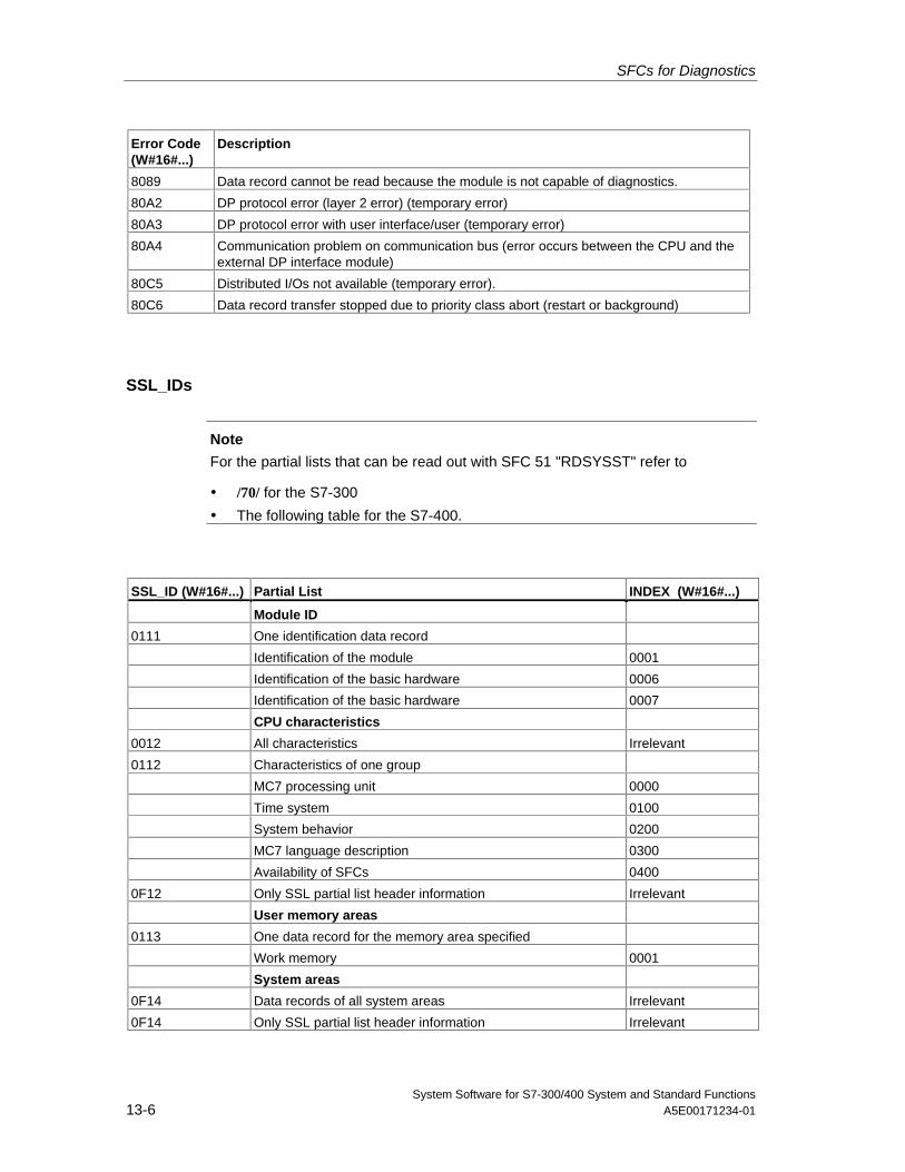
SFCs for Diagnostics
System Software for S7-300/400 System and Standard Functions13-6 A5E00171234-01
Error Code(W#16#...)
Description
8089 Data record cannot be read because the module is not capable of diagnostics.
80A2 DP protocol error (layer 2 error) (temporary error)
80A3 DP protocol error with user interface/user (temporary error)
80A4 Communication problem on communication bus (error occurs between the CPU and theexternal DP interface module)
80C5 Distributed I/Os not available (temporary error).
80C6 Data record transfer stopped due to priority class abort (restart or background)
SSL_IDs
Note
For the partial lists that can be read out with SFC 51 "RDSYSST" refer to
• /70/ for the S7-300
• The following table for the S7-400.
SSL_ID (W#16#...) Partial List INDEX (W#16#...)
Module ID
0111 One identification data record
Identification of the module 0001
Identification of the basic hardware 0006
Identification of the basic hardware 0007
CPU characteristics
0012 All characteristics Irrelevant
0112 Characteristics of one group
MC7 processing unit 0000
Time system 0100
System behavior 0200
MC7 language description 0300
Availability of SFCs 0400
0F12 Only SSL partial list header information Irrelevant
User memory areas
0113 One data record for the memory area specified
Work memory 0001
System areas
0F14 Data records of all system areas Irrelevant
0F14 Only SSL partial list header information Irrelevant
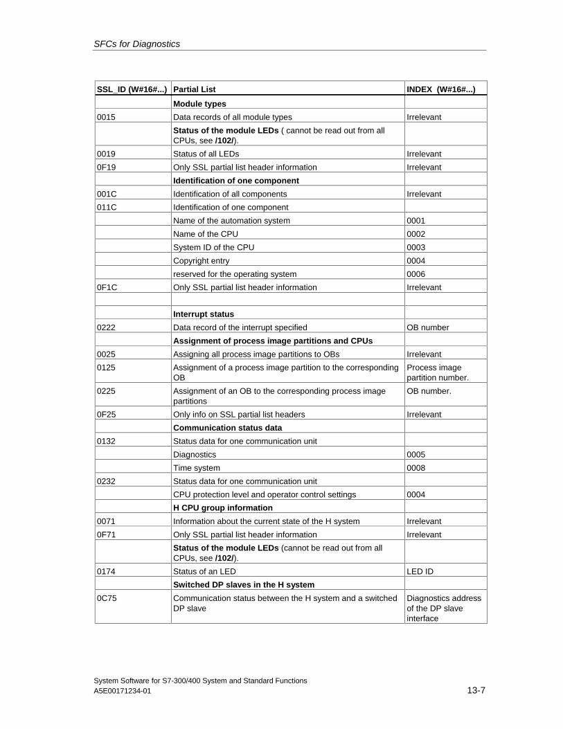
SFCs for Diagnostics
System Software for S7-300/400 System and Standard FunctionsA5E00171234-01 13-7
SSL_ID (W#16#...) Partial List INDEX (W#16#...)
Module types
0015 Data records of all module types Irrelevant
Status of the module LEDs ( cannot be read out from allCPUs, see /102/).
0019 Status of all LEDs Irrelevant
0F19 Only SSL partial list header information Irrelevant
Identification of one component
001C Identification of all components Irrelevant
011C Identification of one component
Name of the automation system 0001
Name of the CPU 0002
System ID of the CPU 0003
Copyright entry 0004
reserved for the operating system 0006
0F1C Only SSL partial list header information Irrelevant
Interrupt status
0222 Data record of the interrupt specified OB number
Assignment of process image partitions and CPUs
0025 Assigning all process image partitions to OBs Irrelevant
0125 Assignment of a process image partition to the correspondingOB
Process imagepartition number.
0225 Assignment of an OB to the corresponding process imagepartitions
OB number.
0F25 Only info on SSL partial list headers Irrelevant
Communication status data
0132 Status data for one communication unit
Diagnostics 0005
Time system 0008
0232 Status data for one communication unit
CPU protection level and operator control settings 0004
H CPU group information
0071 Information about the current state of the H system Irrelevant
0F71 Only SSL partial list header information Irrelevant
Status of the module LEDs (cannot be read out from allCPUs, see /102/).
0174 Status of an LED LED ID
Switched DP slaves in the H system
0C75 Communication status between the H system and a switchedDP slave
Diagnostics addressof the DP slaveinterface
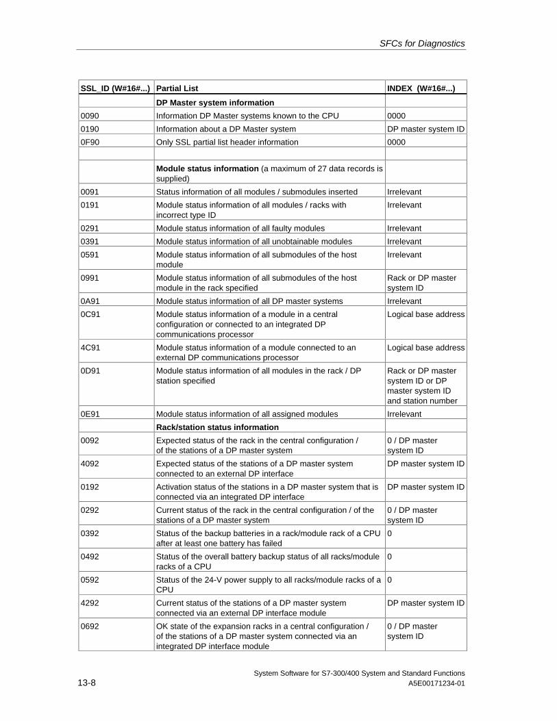
SFCs for Diagnostics
System Software for S7-300/400 System and Standard Functions13-8 A5E00171234-01
SSL_ID (W#16#...) Partial List INDEX (W#16#...)
DP Master system information
0090 Information DP Master systems known to the CPU 0000
0190 Information about a DP Master system DP master system ID
0F90 Only SSL partial list header information 0000
Module status information (a maximum of 27 data records issupplied)
0091 Status information of all modules / submodules inserted Irrelevant
0191 Module status information of all modules / racks withincorrect type ID
Irrelevant
0291 Module status information of all faulty modules Irrelevant
0391 Module status information of all unobtainable modules Irrelevant
0591 Module status information of all submodules of the hostmodule
Irrelevant
0991 Module status information of all submodules of the hostmodule in the rack specified
Rack or DP mastersystem ID
0A91 Module status information of all DP master systems Irrelevant
0C91 Module status information of a module in a centralconfiguration or connected to an integrated DPcommunications processor
Logical base address
4C91 Module status information of a module connected to anexternal DP communications processor
Logical base address
0D91 Module status information of all modules in the rack / DPstation specified
Rack or DP mastersystem ID or DPmaster system IDand station number
0E91 Module status information of all assigned modules Irrelevant
Rack/station status information
0092 Expected status of the rack in the central configuration /of the stations of a DP master system
0 / DP mastersystem ID
4092 Expected status of the stations of a DP master systemconnected to an external DP interface
DP master system ID
0192 Activation status of the stations in a DP master system that isconnected via an integrated DP interface
DP master system ID
0292 Current status of the rack in the central configuration / of thestations of a DP master system
0 / DP mastersystem ID
0392 Status of the backup batteries in a rack/module rack of a CPUafter at least one battery has failed
0
0492 Status of the overall battery backup status of all racks/moduleracks of a CPU
0
0592 Status of the 24-V power supply to all racks/module racks of aCPU
0
4292 Current status of the stations of a DP master systemconnected via an external DP interface module
DP master system ID
0692 OK state of the expansion racks in a central configuration /of the stations of a DP master system connected via anintegrated DP interface module
0 / DP mastersystem ID
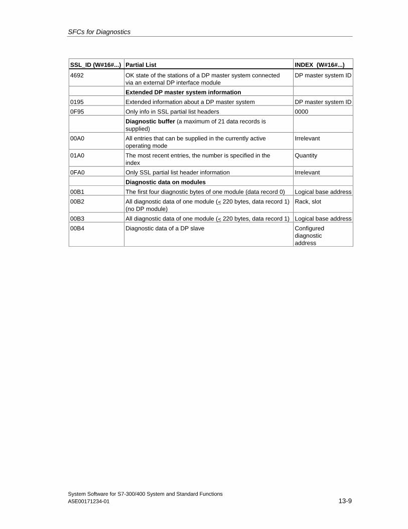
SFCs for Diagnostics
System Software for S7-300/400 System and Standard FunctionsA5E00171234-01 13-9
SSL_ID (W#16#...) Partial List INDEX (W#16#...)
4692 OK state of the stations of a DP master system connectedvia an external DP interface module
DP master system ID
Extended DP master system information
0195 Extended information about a DP master system DP master system ID
0F95 Only info in SSL partial list headers 0000
Diagnostic buffer (a maximum of 21 data records issupplied)
00A0 All entries that can be supplied in the currently activeoperating mode
Irrelevant
01A0 The most recent entries, the number is specified in theindex
Quantity
0FA0 Only SSL partial list header information Irrelevant
Diagnostic data on modules
00B1 The first four diagnostic bytes of one module (data record 0) Logical base address
00B2 All diagnostic data of one module (< 220 bytes, data record 1)(no DP module)
Rack, slot
00B3 All diagnostic data of one module (< 220 bytes, data record 1) Logical base address
00B4 Diagnostic data of a DP slave Configureddiagnosticaddress
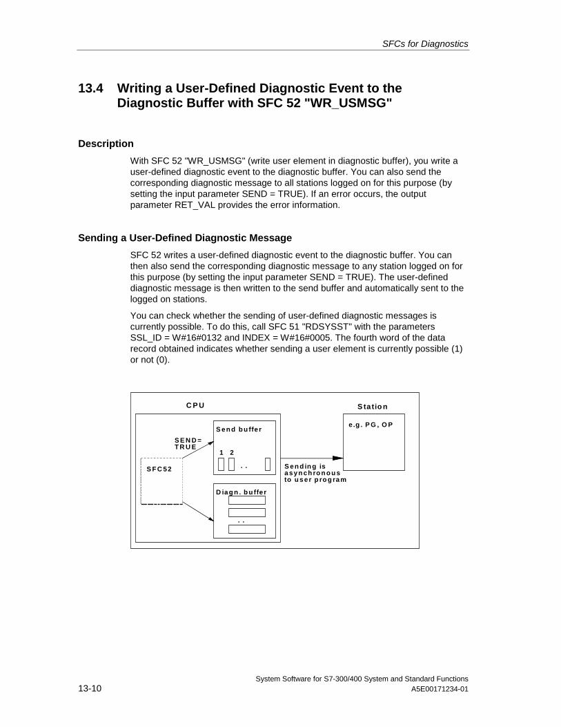
SFCs for Diagnostics
System Software for S7-300/400 System and Standard Functions13-10 A5E00171234-01
13.4 Writing a User-Defined Diagnostic Event to theDiagnostic Buffer with SFC 52 "WR_USMSG"
Description
With SFC 52 "WR_USMSG" (write user element in diagnostic buffer), you write auser-defined diagnostic event to the diagnostic buffer. You can also send thecorresponding diagnostic message to all stations logged on for this purpose (bysetting the input parameter SEND = TRUE). If an error occurs, the outputparameter RET_VAL provides the error information.
Sending a User-Defined Diagnostic Message
SFC 52 writes a user-defined diagnostic event to the diagnostic buffer. You canthen also send the corresponding diagnostic message to any station logged on forthis purpose (by setting the input parameter SEND = TRUE). The user-defineddiagnostic message is then written to the send buffer and automatically sent to thelogged on stations.
You can check whether the sending of user-defined diagnostic messages iscurrently possible. To do this, call SFC 51 "RDSYSST" with the parametersSSL_ID = W#16#0132 and INDEX = W#16#0005. The fourth word of the datarecord obtained indicates whether sending a user element is currently possible (1)or not (0).
C P U
S en d b u ffe r
D iag n . b u ffe r
1 2
. .
. .
S F C 52
S E N D =T R U E
S ta tio n
e.g . P G , O P
S en d in g isasyn ch ro n o u sto u ser p ro g ram
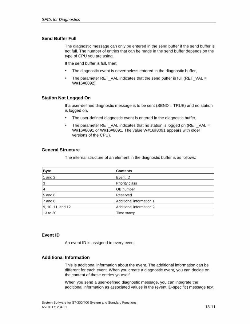
SFCs for Diagnostics
System Software for S7-300/400 System and Standard FunctionsA5E00171234-01 13-11
Send Buffer Full
The diagnostic message can only be entered in the send buffer if the send buffer isnot full. The number of entries that can be made in the send buffer depends on thetype of CPU you are using.
If the send buffer is full, then:
• The diagnostic event is nevertheless entered in the diagnostic buffer,
• The parameter RET_VAL indicates that the send buffer is full (RET_VAL =W#16#8092).
Station Not Logged On
If a user-defined diagnostic message is to be sent (SEND = TRUE) and no stationis logged on,
• The user-defined diagnostic event is entered in the diagnostic buffer,
• The parameter RET_VAL indicates that no station is logged on (RET_VAL =W#16#8091 or W#16#8091. The value W#16#8091 appears with olderversions of the CPU).
General Structure
The internal structure of an element in the diagnostic buffer is as follows:
Byte Contents
1 and 2 Event ID
3 Priority class
4 OB number
5 and 6 Reserved
7 and 8 Additional information 1
9, 10, 11, and 12 Additional information 2
13 to 20 Time stamp
Event ID
An event ID is assigned to every event.
Additional Information
This is additional information about the event. The additional information can bedifferent for each event. When you create a diagnostic event, you can decide onthe content of these entries yourself.
When you send a user-defined diagnostic message, you can integrate theadditional information as associated values in the (event ID-specific) message text.
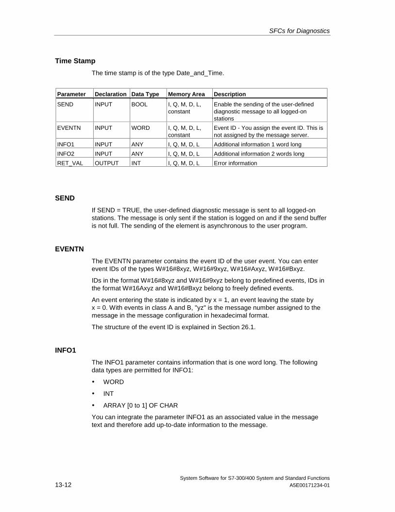
SFCs for Diagnostics
System Software for S7-300/400 System and Standard Functions13-12 A5E00171234-01
Time Stamp
The time stamp is of the type Date_and_Time.
Parameter Declaration Data Type Memory Area Description
SEND INPUT BOOL I, Q, M, D, L,constant
Enable the sending of the user-defineddiagnostic message to all logged-onstations
EVENTN INPUT WORD I, Q, M, D, L,constant
Event ID - You assign the event ID. This isnot assigned by the message server.
INFO1 INPUT ANY I, Q, M, D, L Additional information 1 word long
INFO2 INPUT ANY I, Q, M, D, L Additional information 2 words long
RET_VAL OUTPUT INT I, Q, M, D, L Error information
SEND
If SEND = TRUE, the user-defined diagnostic message is sent to all logged-onstations. The message is only sent if the station is logged on and if the send bufferis not full. The sending of the element is asynchronous to the user program.
EVENTN
The EVENTN parameter contains the event ID of the user event. You can enterevent IDs of the types W#16#8xyz, W#16#9xyz, W#16#Axyz, W#16#Bxyz.
IDs in the format W#16#8xyz and W#16#9xyz belong to predefined events, IDs inthe format W#16Axyz and W#16#Bxyz belong to freely defined events.
An event entering the state is indicated by x = 1, an event leaving the state byx = 0. With events in class A and B, "yz" is the message number assigned to themessage in the message configuration in hexadecimal format.
The structure of the event ID is explained in Section 26.1.
INFO1
The INFO1 parameter contains information that is one word long. The followingdata types are permitted for INFO1:
• WORD
• INT
• ARRAY [0 to 1] OF CHAR
You can integrate the parameter INFO1 as an associated value in the messagetext and therefore add up-to-date information to the message.
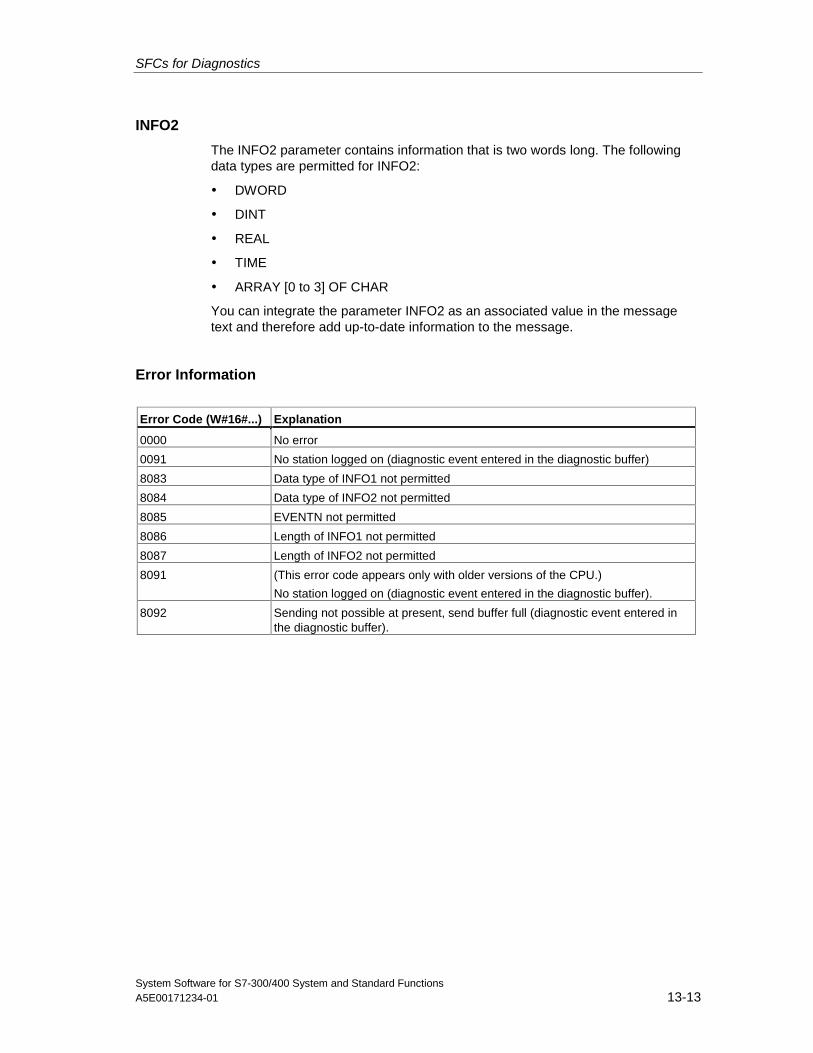
SFCs for Diagnostics
System Software for S7-300/400 System and Standard FunctionsA5E00171234-01 13-13
INFO2
The INFO2 parameter contains information that is two words long. The followingdata types are permitted for INFO2:
• DWORD
• DINT
• REAL
• TIME
• ARRAY [0 to 3] OF CHAR
You can integrate the parameter INFO2 as an associated value in the messagetext and therefore add up-to-date information to the message.
Error Information
Error Code (W#16#...) Explanation
0000 No error
0091 No station logged on (diagnostic event entered in the diagnostic buffer)
8083 Data type of INFO1 not permitted
8084 Data type of INFO2 not permitted
8085 EVENTN not permitted
8086 Length of INFO1 not permitted
8087 Length of INFO2 not permitted
8091 (This error code appears only with older versions of the CPU.)
No station logged on (diagnostic event entered in the diagnostic buffer).
8092 Sending not possible at present, send buffer full (diagnostic event entered inthe diagnostic buffer).
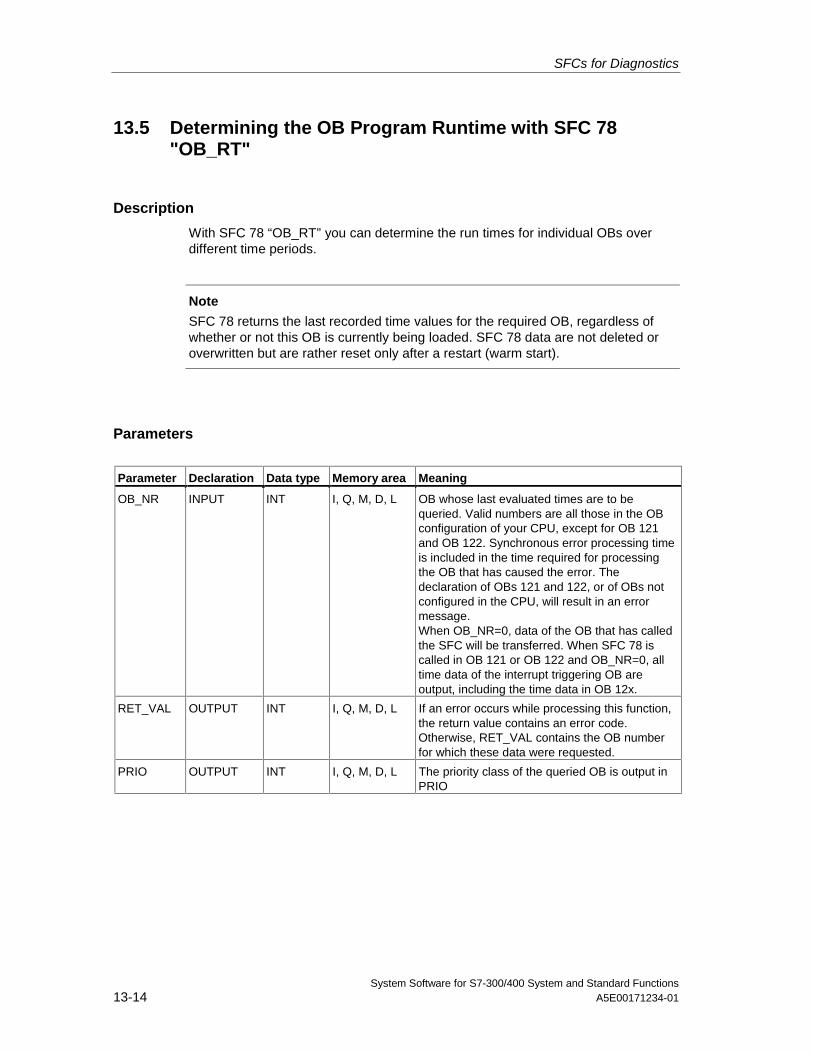
SFCs for Diagnostics
System Software for S7-300/400 System and Standard Functions13-14 A5E00171234-01
13.5 Determining the OB Program Runtime with SFC 78"OB_RT"
Description
With SFC 78 “OB_RT” you can determine the run times for individual OBs overdifferent time periods.
Note
SFC 78 returns the last recorded time values for the required OB, regardless ofwhether or not this OB is currently being loaded. SFC 78 data are not deleted oroverwritten but are rather reset only after a restart (warm start).
Parameters
Parameter Declaration Data type Memory area Meaning
OB_NR INPUT INT I, Q, M, D, L OB whose last evaluated times are to bequeried. Valid numbers are all those in the OBconfiguration of your CPU, except for OB 121and OB 122. Synchronous error processing timeis included in the time required for processingthe OB that has caused the error. Thedeclaration of OBs 121 and 122, or of OBs notconfigured in the CPU, will result in an errormessage.When OB_NR=0, data of the OB that has calledthe SFC will be transferred. When SFC 78 iscalled in OB 121 or OB 122 and OB_NR=0, alltime data of the interrupt triggering OB areoutput, including the time data in OB 12x.
RET_VAL OUTPUT INT I, Q, M, D, L If an error occurs while processing this function,the return value contains an error code.Otherwise, RET_VAL contains the OB numberfor which these data were requested.
PRIO OUTPUT INT I, Q, M, D, L The priority class of the queried OB is output inPRIO
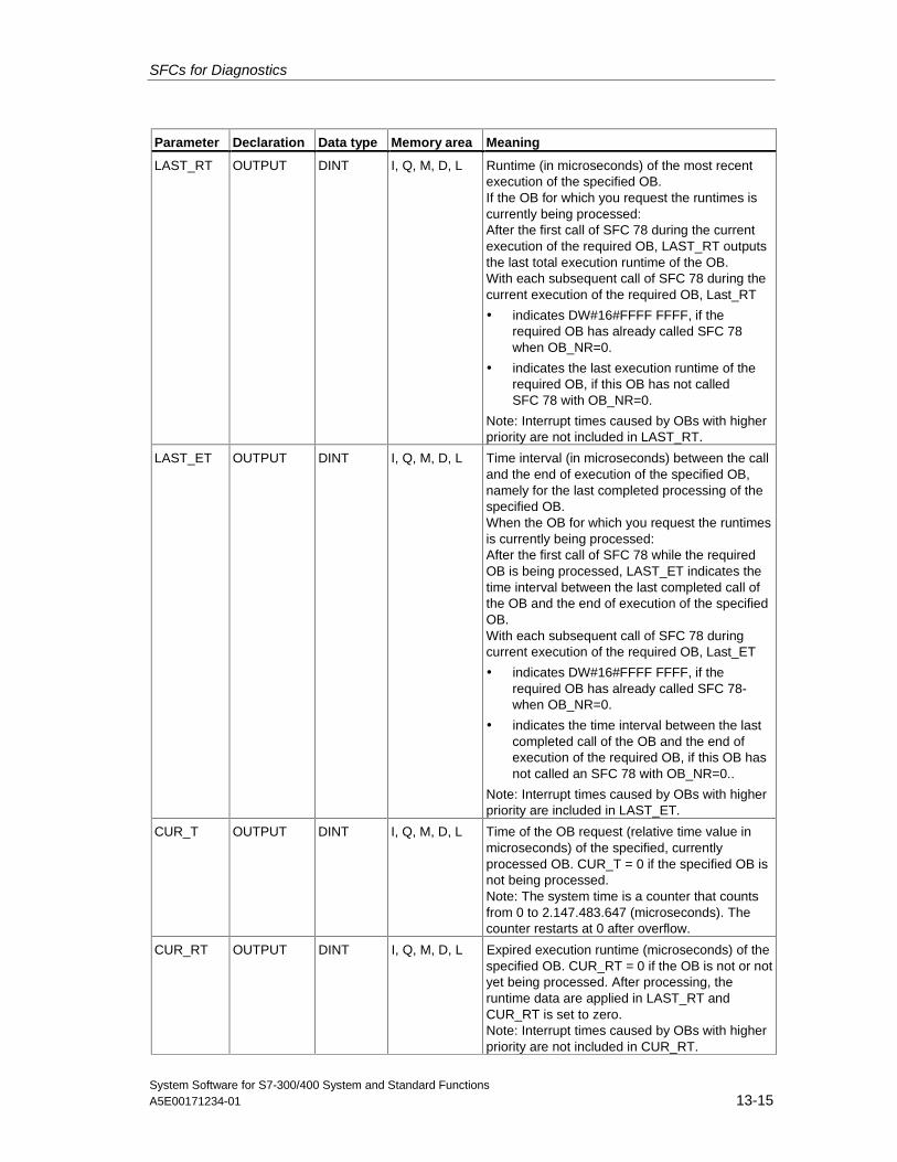
SFCs for Diagnostics
System Software for S7-300/400 System and Standard FunctionsA5E00171234-01 13-15
Parameter Declaration Data type Memory area Meaning
LAST_RT OUTPUT DINT I, Q, M, D, L Runtime (in microseconds) of the most recentexecution of the specified OB.If the OB for which you request the runtimes iscurrently being processed:After the first call of SFC 78 during the currentexecution of the required OB, LAST_RT outputsthe last total execution runtime of the OB.With each subsequent call of SFC 78 during thecurrent execution of the required OB, Last_RT
• indicates DW#16#FFFF FFFF, if therequired OB has already called SFC 78when OB_NR=0.
• indicates the last execution runtime of therequired OB, if this OB has not calledSFC 78 with OB_NR=0.
Note: Interrupt times caused by OBs with higherpriority are not included in LAST_RT.
LAST_ET OUTPUT DINT I, Q, M, D, L Time interval (in microseconds) between the calland the end of execution of the specified OB,namely for the last completed processing of thespecified OB.When the OB for which you request the runtimesis currently being processed:After the first call of SFC 78 while the requiredOB is being processed, LAST_ET indicates thetime interval between the last completed call ofthe OB and the end of execution of the specifiedOB.With each subsequent call of SFC 78 duringcurrent execution of the required OB, Last_ET
• indicates DW#16#FFFF FFFF, if therequired OB has already called SFC 78-when OB_NR=0.
• indicates the time interval between the lastcompleted call of the OB and the end ofexecution of the required OB, if this OB hasnot called an SFC 78 with OB_NR=0..
Note: Interrupt times caused by OBs with higherpriority are included in LAST_ET.
CUR_T OUTPUT DINT I, Q, M, D, L Time of the OB request (relative time value inmicroseconds) of the specified, currentlyprocessed OB. CUR_T = 0 if the specified OB isnot being processed.Note: The system time is a counter that countsfrom 0 to 2.147.483.647 (microseconds). Thecounter restarts at 0 after overflow.
CUR_RT OUTPUT DINT I, Q, M, D, L Expired execution runtime (microseconds) of thespecified OB. CUR_RT = 0 if the OB is not or notyet being processed. After processing, theruntime data are applied in LAST_RT andCUR_RT is set to zero.Note: Interrupt times caused by OBs with higherpriority are not included in CUR_RT.
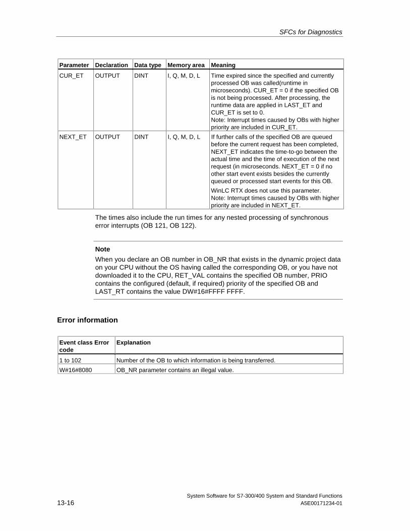
SFCs for Diagnostics
System Software for S7-300/400 System and Standard Functions13-16 A5E00171234-01
Parameter Declaration Data type Memory area Meaning
CUR_ET OUTPUT DINT I, Q, M, D, L Time expired since the specified and currentlyprocessed OB was called(runtime inmicroseconds). CUR_ET = 0 if the specified OBis not being processed. After processing, theruntime data are applied in LAST_ET andCUR_ET is set to 0.Note: Interrupt times caused by OBs with higherpriority are included in CUR_ET.
NEXT_ET OUTPUT DINT I, Q, M, D, L If further calls of the specified OB are queuedbefore the current request has been completed,NEXT_ET indicates the time-to-go between theactual time and the time of execution of the nextrequest (in microseconds. NEXT_ET = 0 if noother start event exists besides the currentlyqueued or processed start events for this OB.
WinLC RTX does not use this parameter.Note: Interrupt times caused by OBs with higherpriority are included in NEXT_ET.
The times also include the run times for any nested processing of synchronouserror interrupts (OB 121, OB 122).
Note
When you declare an OB number in OB_NR that exists in the dynamic project dataon your CPU without the OS having called the corresponding OB, or you have notdownloaded it to the CPU, RET_VAL contains the specified OB number, PRIOcontains the configured (default, if required) priority of the specified OB andLAST_RT contains the value DW#16#FFFF FFFF.
Error information
Event class Errorcode
Explanation
1 to 102 Number of the OB to which information is being transferred.
W#16#8080 OB_NR parameter contains an illegal value.
SFCs for Diagnostics
System Software for S7-300/400 System and Standard FunctionsA5E00171234-01 13-17
13.6 Diagnosis of the Current Connection Status with SFC 87"C_DIAG"
Description
You can use SFC 87 "C_DIAG" to determine the current status of all S7connections and of all fault-tolerant S7 connections (or their partial connection).
Suitable evaluation of these connection data lets you recognize failures of S7connections as well as of fault-tolerant S7 connections and report these, should theoccasion arise, to an operating and visualization system. Monitored connectionscan be a connection between automation systems as well as the connection of anautomation system to an operating and visualization system.
Note
A change in the operating state of the CPU: RUN -> STOP ->RUN, does not affectthe state of the configured connections. Exception: When an H station changesfrom the Redundant system state to the Stop system state, the partial connectionsof all fault-tolerant connections to the standby CPU will be disconnected.
After a power failure, on the other hand, all configured connections will bereestablished and this changes the connection status.
The first time SFC 87 is called during or after startup, the connection informationwill differ, depending on whether the last operating mode of the CPU was STOP orPOWER OFF
Operating Mode
The SFC 87 "C_DIAG" is an asynchronous SFC operation, that is to say,processing can be extended over multiple SFC calls.
You start the job by calling the SFC 87 with REQ=1.
If it was possible to execute the job immediately, the SFC returns the value 0 in theoutput parameter BUSY. If BUSY is 1 the job is still active.
When Do You Call the SFC 87?
To recognize the failure of S7 connections and fault-tolerant S7 connections, callthe SFC87 in a cyclic interrupt OB that is started, for example, every 10 secondsby the operating system.
Since the status of a connection normally does not change, it is appropriate to copythe connection data to the user program with these cyclic calls only if they havechanged since their last call (call with MODE=B#16#02, see below).
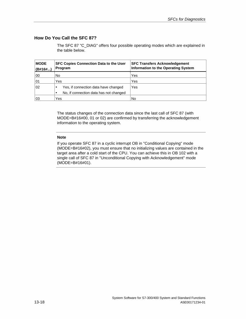
SFCs for Diagnostics
System Software for S7-300/400 System and Standard Functions13-18 A5E00171234-01
How Do You Call the SFC 87?
The SFC 87 "C_DIAG" offers four possible operating modes which are explained inthe table below.
MODE
(B#16#...)
SFC Copies Connection Data to the UserProgram
SFC Transfers AcknowledgementInformation to the Operating System
00 No Yes
01 Yes Yes
02 • Yes, if connection data have changed
• No, if connection data has not changed
Yes
03 Yes No
The status changes of the connection data since the last call of SFC 87 (withMODE=B#16#00, 01 or 02) are confirmed by transferring the acknowledgementinformation to the operating system.
Note
If you operate SFC 87 in a cyclic interrupt OB in "Conditional Copying" mode(MODE=B#16#02), you must ensure that no initializing values are contained in thetarget area after a cold start of the CPU. You can achieve this in OB 102 with asingle call of SFC 87 in "Unconditional Copying with Acknowledgement" mode(MODE=B#16#01).
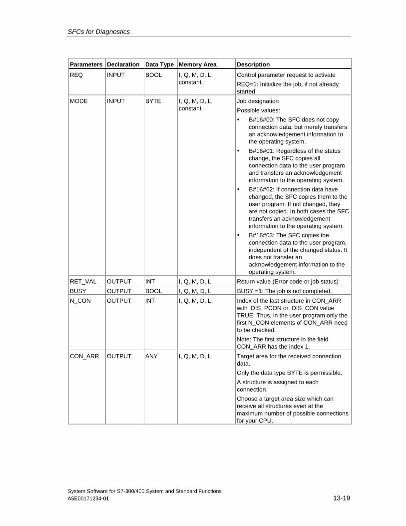
SFCs for Diagnostics
System Software for S7-300/400 System and Standard FunctionsA5E00171234-01 13-19
Parameters Declaration Data Type Memory Area Description
REQ INPUT BOOL I, Q, M, D, L,constant.
Control parameter request to activate
REQ=1: Initialize the job, if not alreadystarted
MODE INPUT BYTE I, Q, M, D, L,constant.
Job designation
Possible values:
• B#16#00: The SFC does not copyconnection data, but merely transfersan acknowledgement information tothe operating system.
• B#16#01: Regardless of the statuschange, the SFC copies allconnection data to the user programand transfers an acknowledgementinformation to the operating system.
• B#16#02: If connection data havechanged, the SFC copies them to theuser program. If not changed, theyare not copied. In both cases the SFCtransfers an acknowledgementinformation to the operating system.
• B#16#03: The SFC copies theconnection data to the user program,independent of the changed status. Itdoes not transfer anacknowledgement information to theoperating system.
RET_VAL OUTPUT INT I, Q, M, D, L Return value (Error code or job status)
BUSY OUTPUT BOOL I, Q, M, D, L BUSY =1: The job is not completed.
N_CON OUTPUT INT I, Q, M, D, L Index of the last structure in CON_ARRwith .DIS_PCON or .DIS_CON valueTRUE. Thus, in the user program only thefirst N_CON elements of CON_ARR needto be checked.
Note: The first structure in the fieldCON_ARR has the index 1.
CON_ARR OUTPUT ANY I, Q, M, D, L Target area for the received connectiondata.
Only the data type BYTE is permissible.
A structure is assigned to eachconnection.
Choose a target area size which canreceive all structures even at themaximum number of possible connectionsfor your CPU.
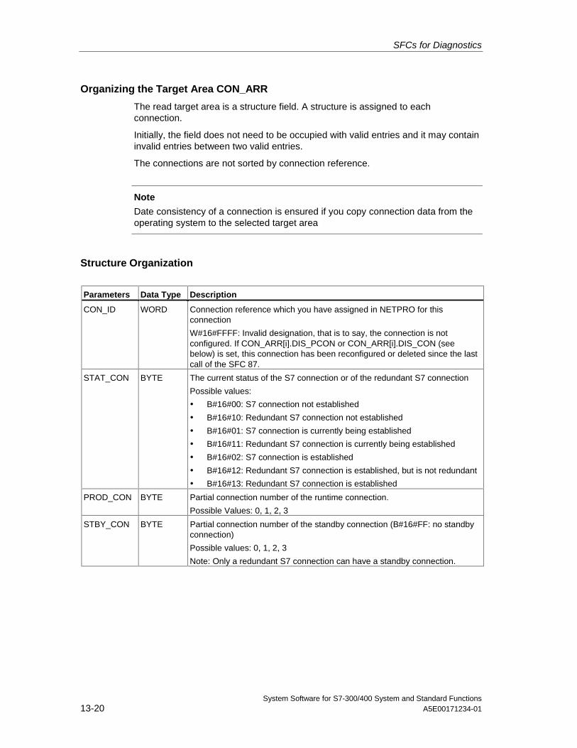
SFCs for Diagnostics
System Software for S7-300/400 System and Standard Functions13-20 A5E00171234-01
Organizing the Target Area CON_ARR
The read target area is a structure field. A structure is assigned to eachconnection.
Initially, the field does not need to be occupied with valid entries and it may containinvalid entries between two valid entries.
The connections are not sorted by connection reference.
Note
Date consistency of a connection is ensured if you copy connection data from theoperating system to the selected target area
Structure Organization
Parameters Data Type Description
CON_ID WORD Connection reference which you have assigned in NETPRO for thisconnection
W#16#FFFF: Invalid designation, that is to say, the connection is notconfigured. If CON_ARR[i].DIS_PCON or CON_ARR[i].DIS_CON (seebelow) is set, this connection has been reconfigured or deleted since the lastcall of the SFC 87.
STAT_CON BYTE The current status of the S7 connection or of the redundant S7 connection
Possible values:
• B#16#00: S7 connection not established
• B#16#10: Redundant S7 connection not established
• B#16#01: S7 connection is currently being established
• B#16#11: Redundant S7 connection is currently being established
• B#16#02: S7 connection is established
• B#16#12: Redundant S7 connection is established, but is not redundant
• B#16#13: Redundant S7 connection is established
PROD_CON BYTE Partial connection number of the runtime connection.
Possible Values: 0, 1, 2, 3
STBY_CON BYTE Partial connection number of the standby connection (B#16#FF: no standbyconnection)
Possible values: 0, 1, 2, 3
Note: Only a redundant S7 connection can have a standby connection.
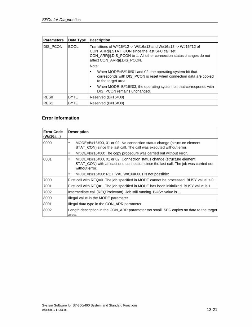
SFCs for Diagnostics
System Software for S7-300/400 System and Standard FunctionsA5E00171234-01 13-21
Parameters Data Type Description
DIS_PCON BOOL Transitions of W#16#12 -> W#16#13 and W#16#13 -> W#16#12 ofCON_ARR[i].STAT_CON since the last SFC call setCON_ARR[i].DIS_PCON to 1. All other connection status changes do notaffect CON_ARR[i].DIS_PCON.
Note:
• When MODE=B#16#01 and 02, the operating system bit thatcorresponds with DIS_PCON is reset when connection data are copiedto the target area.
• When MODE=B#16#03, the operating system bit that corresponds withDIS_PCON remains unchanged.
RES0 BYTE Reserved (B#16#00)
RES1 BYTE Reserved (B#16#00)
Error Information
Error Code(W#16#...)
Description
0000 • MODE=B#16#00, 01 or 02: No connection status change (structure elementSTAT_CON) since the last call. The call was executed without error.
• MODE=B#16#03: The copy procedure was carried out without error.
0001 • MODE=B#16#00, 01 or 02: Connection status change (structure elementSTAT_CON) with at least one connection since the last call. The job was carried outwithout error.
• MODE=B#16#03: RET_VAL W#16#0001 is not possible:
7000 First call with REQ=0. The job specified in MODE cannot be processed. BUSY value is 0.
7001 First call with REQ=1. The job specified in MODE has been initialized. BUSY value is 1
7002 Intermediate call (REQ irrelevant). Job still running. BUSY value is 1.
8000 Illegal value in the MODE parameter .
8001 Illegal data type in the CON_ARR parameter .
8002 Length description in the CON_ARR parameter too small. SFC copies no data to the targetarea.
SFCs for Diagnostics
System Software for S7-300/400 System and Standard Functions13-22 A5E00171234-01
13.7 Identifying the Bus Topology of a DP Master System withSFC 103 "DP_TOPOL"
DescriptionCall SFC 103 "DP_TOPOL" with its diagnostics repeaters to initiate theidentification of the bus topology of a selected a DP master system. All diagnosticsrepeaters connected to a DP master system are addressed when SFC 103 iscalled.
Note
The topology of only one DP master system can be identified at a given time.
The identification of the topology is a prerequisite for a detailed display of the errorlocation in the event of a line error. After the installation or any changes to thephysical structure of a DP master system, once again identify the topology withSFC 103.
Changes to the physical structure includes:
• Change in cable lengths
• Addition or removal of nodes or of components with repeater function
• Change in node addresses
Each diagnostic repeater enters the result (PROFIBUS address of all nodes andtheir absolute distance to the diagnostic repeater) in a topology table. You can readthese values under STEP 7.
We recommend to call SFC 103 in OB1 or in a watchdog interrupt OB. An S7-300does not allow this call in one of the startup OBs.
The SFC writes error messages returned by the diagnostic repeater to the outputsDPR and DPRI. If more than one diagnostic repeater in the selected DP mastersystem reports an error, the SFC enters in DPR and DPRI only information relevantto the diagnostic repeater that has first generated an error message. Call SFC 13"DPNRM_DG" or STEP 7 to read the complete diagnostic information. The value ofoutputs DPR and DPRI is NULL if no error is reported by a diagnostic repeater.
Operating methodSFC 103 "DP_TOPOL" operates asynchronously, that is, its execution requiresseveral SFC calls. Call SFC 103 with REQ = 1 to initiate identification of the DPbus topology and call SFC 103 with R=1 to abort the process.
The job status is indicated at the output parameters RET_VAL and BUSY, see alsoMeaning of REQ, RET_VAL and BUSY with asynchronously operating SFCs.
Note
It may take several minutes to identify the topology.
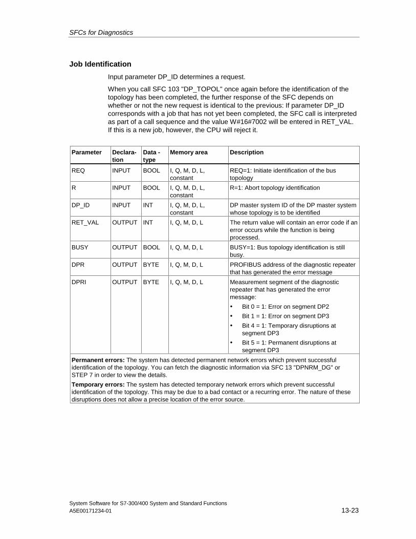
SFCs for Diagnostics
System Software for S7-300/400 System and Standard FunctionsA5E00171234-01 13-23
Job Identification
Input parameter DP_ID determines a request.
When you call SFC 103 "DP_TOPOL" once again before the identification of thetopology has been completed, the further response of the SFC depends onwhether or not the new request is identical to the previous: If parameter DP_IDcorresponds with a job that has not yet been completed, the SFC call is interpretedas part of a call sequence and the value W#16#7002 will be entered in RET_VAL.If this is a new job, however, the CPU will reject it.
Parameter Declara-tion
Data -type
Memory area Description
REQ INPUT BOOL I, Q, M, D, L,constant
REQ=1: Initiate identification of the bustopology
R INPUT BOOL I, Q, M, D, L,constant
R=1: Abort topology identification
DP_ID INPUT INT I, Q, M, D, L,constant
DP master system ID of the DP master systemwhose topology is to be identified
RET_VAL OUTPUT INT I, Q, M, D, L The return value will contain an error code if anerror occurs while the function is beingprocessed.
BUSY OUTPUT BOOL I, Q, M, D, L BUSY=1: Bus topology identification is stillbusy.
DPR OUTPUT BYTE I, Q, M, D, L PROFIBUS address of the diagnostic repeaterthat has generated the error message
DPRI OUTPUT BYTE I, Q, M, D, L Measurement segment of the diagnosticrepeater that has generated the errormessage:
• Bit 0 = 1: Error on segment DP2
• Bit 1 = 1: Error on segment DP3
• Bit 4 = 1: Temporary disruptions atsegment DP3
• Bit 5 = 1: Permanent disruptions atsegment DP3
Permanent errors: The system has detected permanent network errors which prevent successfulidentification of the topology. You can fetch the diagnostic information via SFC 13 "DPNRM_DG" orSTEP 7 in order to view the details.
Temporary errors: The system has detected temporary network errors which prevent successfulidentification of the topology. This may be due to a bad contact or a recurring error. The nature of thesedisruptions does not allow a precise location of the error source.
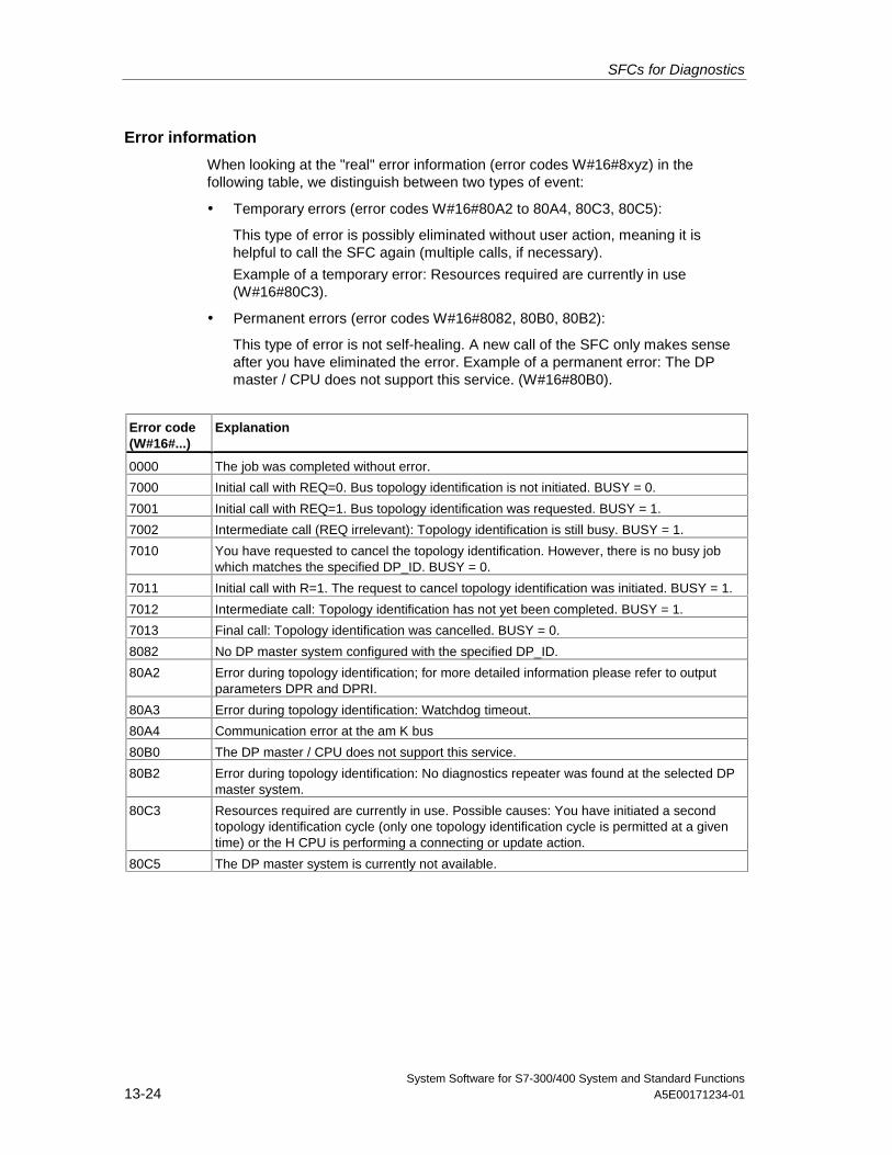
SFCs for Diagnostics
System Software for S7-300/400 System and Standard Functions13-24 A5E00171234-01
Error information
When looking at the "real" error information (error codes W#16#8xyz) in thefollowing table, we distinguish between two types of event:
• Temporary errors (error codes W#16#80A2 to 80A4, 80C3, 80C5):
This type of error is possibly eliminated without user action, meaning it ishelpful to call the SFC again (multiple calls, if necessary).
Example of a temporary error: Resources required are currently in use(W#16#80C3).
• Permanent errors (error codes W#16#8082, 80B0, 80B2):
This type of error is not self-healing. A new call of the SFC only makes senseafter you have eliminated the error. Example of a permanent error: The DPmaster / CPU does not support this service. (W#16#80B0).
Error code(W#16#...)
Explanation
0000 The job was completed without error.
7000 Initial call with REQ=0. Bus topology identification is not initiated. BUSY = 0.
7001 Initial call with REQ=1. Bus topology identification was requested. BUSY = 1.
7002 Intermediate call (REQ irrelevant): Topology identification is still busy. BUSY = 1.
7010 You have requested to cancel the topology identification. However, there is no busy jobwhich matches the specified DP_ID. BUSY = 0.
7011 Initial call with R=1. The request to cancel topology identification was initiated. BUSY = 1.
7012 Intermediate call: Topology identification has not yet been completed. BUSY = 1.
7013 Final call: Topology identification was cancelled. BUSY = 0.
8082 No DP master system configured with the specified DP_ID.
80A2 Error during topology identification; for more detailed information please refer to outputparameters DPR and DPRI.
80A3 Error during topology identification: Watchdog timeout.
80A4 Communication error at the am K bus
80B0 The DP master / CPU does not support this service.
80B2 Error during topology identification: No diagnostics repeater was found at the selected DPmaster system.
80C3 Resources required are currently in use. Possible causes: You have initiated a secondtopology identification cycle (only one topology identification cycle is permitted at a giventime) or the H CPU is performing a connecting or update action.
80C5 The DP master system is currently not available.
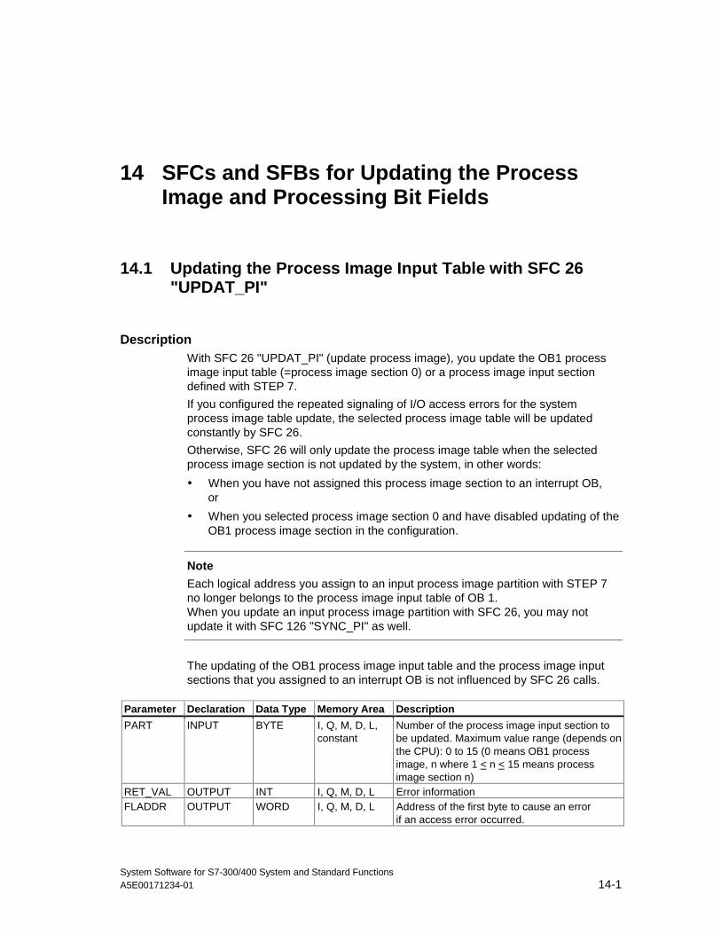
System Software for S7-300/400 System and Standard FunctionsA5E00171234-01 14-1
14 SFCs and SFBs for Updating the ProcessImage and Processing Bit Fields
14.1 Updating the Process Image Input Table with SFC 26"UPDAT_PI"
DescriptionWith SFC 26 "UPDAT_PI" (update process image), you update the OB1 processimage input table (=process image section 0) or a process image input sectiondefined with STEP 7.
If you configured the repeated signaling of I/O access errors for the systemprocess image table update, the selected process image table will be updatedconstantly by SFC 26.
Otherwise, SFC 26 will only update the process image table when the selectedprocess image section is not updated by the system, in other words:
• When you have not assigned this process image section to an interrupt OB,or
• When you selected process image section 0 and have disabled updating of theOB1 process image section in the configuration.
Note
Each logical address you assign to an input process image partition with STEP 7no longer belongs to the process image input table of OB 1.When you update an input process image partition with SFC 26, you may notupdate it with SFC 126 "SYNC_PI" as well.
The updating of the OB1 process image input table and the process image inputsections that you assigned to an interrupt OB is not influenced by SFC 26 calls.
Parameter Declaration Data Type Memory Area Description
PART INPUT BYTE I, Q, M, D, L,constant
Number of the process image input section tobe updated. Maximum value range (depends onthe CPU): 0 to 15 (0 means OB1 processimage, n where 1 < n < 15 means process image section n)
RET_VAL OUTPUT INT I, Q, M, D, L Error informationFLADDR OUTPUT WORD I, Q, M, D, L Address of the first byte to cause an error
if an access error occurred.
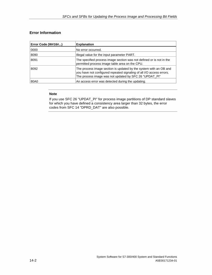
SFCs and SFBs for Updating the Process Image and Processing Bit Fields
System Software for S7-300/400 System and Standard Functions14-2 A5E00171234-01
Error Information
Error Code (W#16#...) Explanation
0000 No error occurred.
8090 Illegal value for the input parameter PART.
8091 The specified process image section was not defined or is not in thepermitted process image table area on the CPU.
8092 The process image section is updated by the system with an OB andyou have not configured repeated signaling of all I/O access errors.The process image was not updated by SFC 26 "UPDAT_PI"
80A0 An access error was detected during the updating.
Note
If you use SFC 26 "UPDAT_PI" for process image partitions of DP standard slavesfor which you have defined a consistency area larger than 32 bytes, the errorcodes from SFC 14 "DPRD_DAT" are also possible.
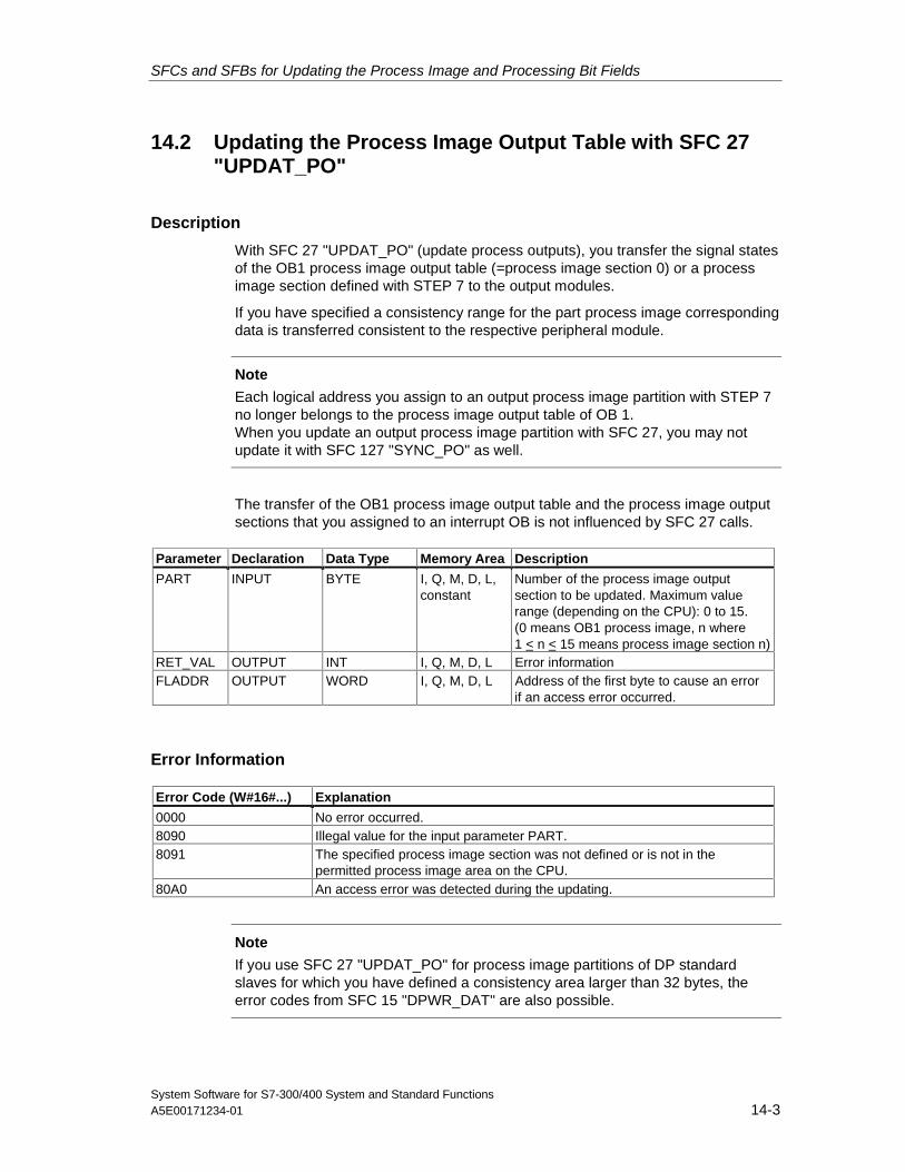
SFCs and SFBs for Updating the Process Image and Processing Bit Fields
System Software for S7-300/400 System and Standard FunctionsA5E00171234-01 14-3
14.2 Updating the Process Image Output Table with SFC 27"UPDAT_PO"
Description
With SFC 27 "UPDAT_PO" (update process outputs), you transfer the signal statesof the OB1 process image output table (=process image section 0) or a processimage section defined with STEP 7 to the output modules.
If you have specified a consistency range for the part process image correspondingdata is transferred consistent to the respective peripheral module.
Note
Each logical address you assign to an output process image partition with STEP 7no longer belongs to the process image output table of OB 1.When you update an output process image partition with SFC 27, you may notupdate it with SFC 127 "SYNC_PO" as well.
The transfer of the OB1 process image output table and the process image outputsections that you assigned to an interrupt OB is not influenced by SFC 27 calls.
Parameter Declaration Data Type Memory Area Description
PART INPUT BYTE I, Q, M, D, L,constant
Number of the process image outputsection to be updated. Maximum valuerange (depending on the CPU): 0 to 15.(0 means OB1 process image, n where1 < n < 15 means process image section n)
RET_VAL OUTPUT INT I, Q, M, D, L Error informationFLADDR OUTPUT WORD I, Q, M, D, L Address of the first byte to cause an error
if an access error occurred.
Error Information
Error Code (W#16#...) Explanation
0000 No error occurred.8090 Illegal value for the input parameter PART.8091 The specified process image section was not defined or is not in the
permitted process image area on the CPU.80A0 An access error was detected during the updating.
Note
If you use SFC 27 "UPDAT_PO" for process image partitions of DP standardslaves for which you have defined a consistency area larger than 32 bytes, theerror codes from SFC 15 "DPWR_DAT" are also possible.
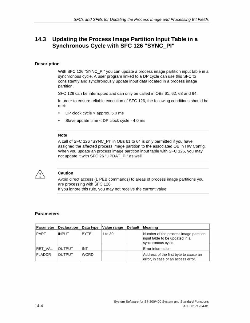
SFCs and SFBs for Updating the Process Image and Processing Bit Fields
System Software for S7-300/400 System and Standard Functions14-4 A5E00171234-01
14.3 Updating the Process Image Partition Input Table in aSynchronous Cycle with SFC 126 "SYNC_PI"
Description
With SFC 126 "SYNC_PI“ you can update a process image partition input table in asynchronous cycle. A user program linked to a DP cycle can use this SFC toconsistently and synchronously update input data located in a process imagepartition.
SFC 126 can be interrupted and can only be called in OBs 61, 62, 63 and 64.
In order to ensure reliable execution of SFC 126, the following conditions should bemet:
• DP clock cycle > approx. 5.0 ms
• Slave update time < DP clock cycle - 4.0 ms
Note
A call of SFC 126 "SYNC_PI" in OBs 61 to 64 is only permitted if you haveassigned the affected process image partition to the associated OB in HW Config.When you update an process image partition input table with SFC 126, you maynot update it with SFC 26 "UPDAT_PI" as well.
! Caution
Avoid direct access (L PEB commands) to areas of process image partitions youare processing with SFC 126.If you ignore this rule, you may not receive the current value.
Parameters
Parameter Declaration Data type Value range Default Meaning
PART INPUT BYTE 1 to 30 Number of the process image partitioninput table to be updated in asynchronous cycle.
RET_VAL OUTPUT INT Error information
FLADDR OUTPUT WORD Address of the first byte to cause anerror, in case of an access error.
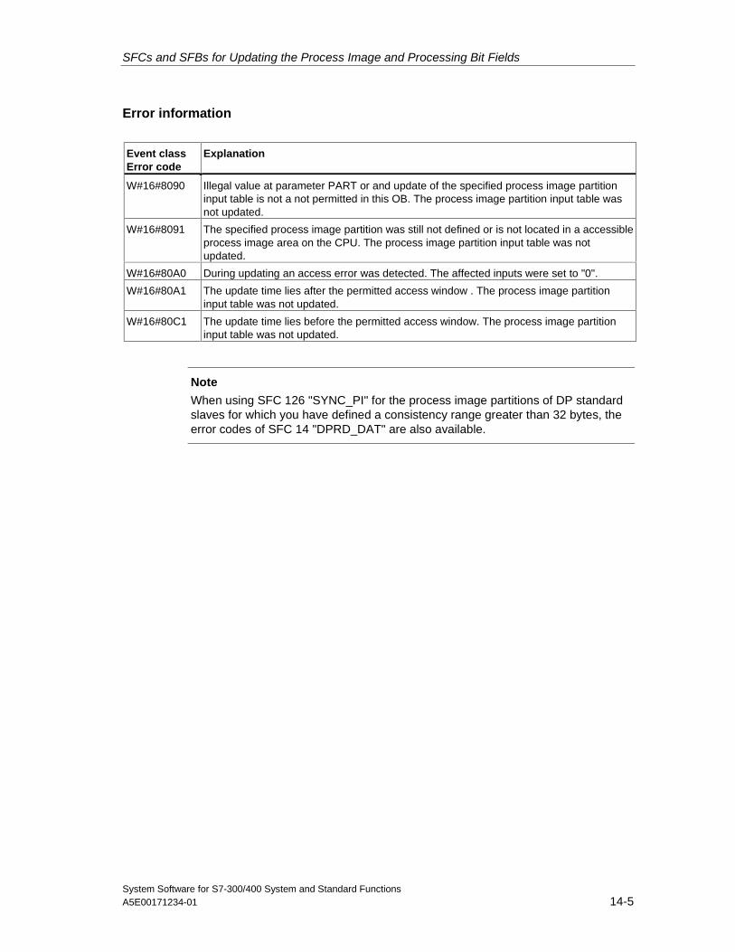
SFCs and SFBs for Updating the Process Image and Processing Bit Fields
System Software for S7-300/400 System and Standard FunctionsA5E00171234-01 14-5
Error information
Event classError code
Explanation
W#16#8090 Illegal value at parameter PART or and update of the specified process image partitioninput table is not a not permitted in this OB. The process image partition input table wasnot updated.
W#16#8091 The specified process image partition was still not defined or is not located in a accessibleprocess image area on the CPU. The process image partition input table was notupdated.
W#16#80A0 During updating an access error was detected. The affected inputs were set to "0".
W#16#80A1 The update time lies after the permitted access window . The process image partitioninput table was not updated.
W#16#80C1 The update time lies before the permitted access window. The process image partitioninput table was not updated.
Note
When using SFC 126 "SYNC_PI" for the process image partitions of DP standardslaves for which you have defined a consistency range greater than 32 bytes, theerror codes of SFC 14 "DPRD_DAT" are also available.
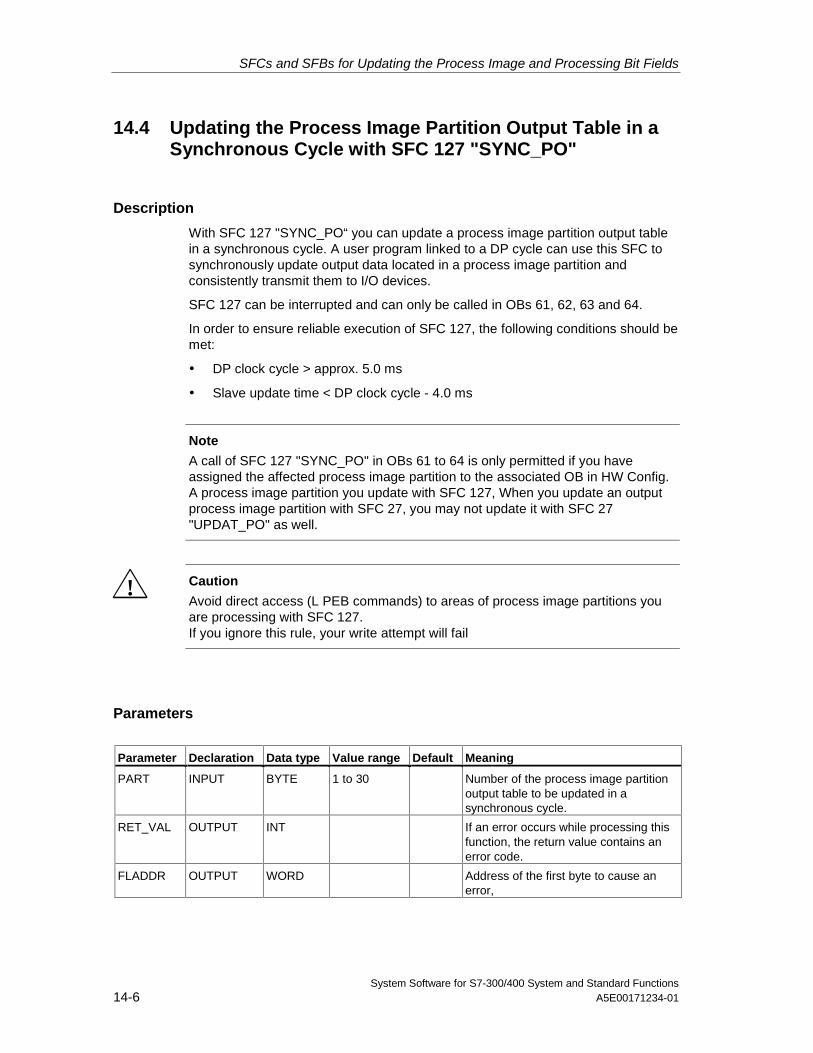
SFCs and SFBs for Updating the Process Image and Processing Bit Fields
System Software for S7-300/400 System and Standard Functions14-6 A5E00171234-01
14.4 Updating the Process Image Partition Output Table in aSynchronous Cycle with SFC 127 "SYNC_PO"
Description
With SFC 127 "SYNC_PO“ you can update a process image partition output tablein a synchronous cycle. A user program linked to a DP cycle can use this SFC tosynchronously update output data located in a process image partition andconsistently transmit them to I/O devices.
SFC 127 can be interrupted and can only be called in OBs 61, 62, 63 and 64.
In order to ensure reliable execution of SFC 127, the following conditions should bemet:
• DP clock cycle > approx. 5.0 ms
• Slave update time < DP clock cycle - 4.0 ms
Note
A call of SFC 127 "SYNC_PO" in OBs 61 to 64 is only permitted if you haveassigned the affected process image partition to the associated OB in HW Config.A process image partition you update with SFC 127, When you update an outputprocess image partition with SFC 27, you may not update it with SFC 27"UPDAT_PO" as well.
! Caution
Avoid direct access (L PEB commands) to areas of process image partitions youare processing with SFC 127.If you ignore this rule, your write attempt will fail
Parameters
Parameter Declaration Data type Value range Default Meaning
PART INPUT BYTE 1 to 30 Number of the process image partitionoutput table to be updated in asynchronous cycle.
RET_VAL OUTPUT INT If an error occurs while processing thisfunction, the return value contains anerror code.
FLADDR OUTPUT WORD Address of the first byte to cause anerror,
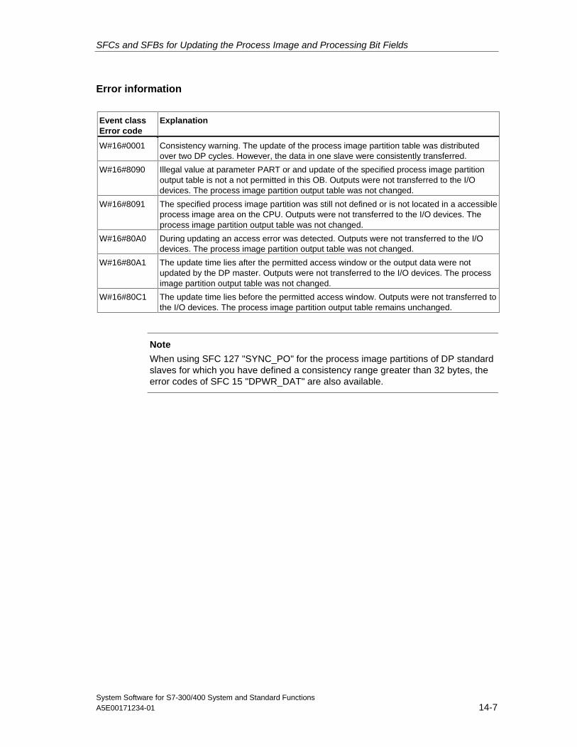
SFCs and SFBs for Updating the Process Image and Processing Bit Fields
System Software for S7-300/400 System and Standard FunctionsA5E00171234-01 14-7
Error information
Event classError code
Explanation
W#16#0001 Consistency warning. The update of the process image partition table was distributedover two DP cycles. However, the data in one slave were consistently transferred.
W#16#8090 Illegal value at parameter PART or and update of the specified process image partitionoutput table is not a not permitted in this OB. Outputs were not transferred to the I/Odevices. The process image partition output table was not changed.
W#16#8091 The specified process image partition was still not defined or is not located in a accessibleprocess image area on the CPU. Outputs were not transferred to the I/O devices. Theprocess image partition output table was not changed.
W#16#80A0 During updating an access error was detected. Outputs were not transferred to the I/Odevices. The process image partition output table was not changed.
W#16#80A1 The update time lies after the permitted access window or the output data were notupdated by the DP master. Outputs were not transferred to the I/O devices. The processimage partition output table was not changed.
W#16#80C1 The update time lies before the permitted access window. Outputs were not transferred tothe I/O devices. The process image partition output table remains unchanged.
Note
When using SFC 127 "SYNC_PO" for the process image partitions of DP standardslaves for which you have defined a consistency range greater than 32 bytes, theerror codes of SFC 15 "DPWR_DAT" are also available.
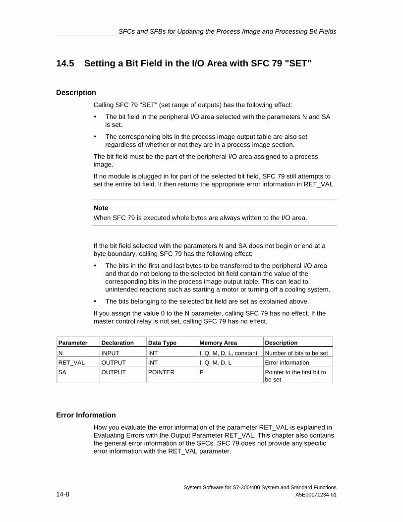
SFCs and SFBs for Updating the Process Image and Processing Bit Fields
System Software for S7-300/400 System and Standard Functions14-8 A5E00171234-01
14.5 Setting a Bit Field in the I/O Area with SFC 79 "SET"
Description
Calling SFC 79 "SET" (set range of outputs) has the following effect:
• The bit field in the peripheral I/O area selected with the parameters N and SAis set.
• The corresponding bits in the process image output table are also setregardless of whether or not they are in a process image section.
The bit field must be the part of the peripheral I/O area assigned to a processimage.
If no module is plugged in for part of the selected bit field, SFC 79 still attempts toset the entire bit field. It then returns the appropriate error information in RET_VAL.
Note
When SFC 79 is executed whole bytes are always written to the I/O area.
If the bit field selected with the parameters N and SA does not begin or end at abyte boundary, calling SFC 79 has the following effect:
• The bits in the first and last bytes to be transferred to the peripheral I/O areaand that do not belong to the selected bit field contain the value of thecorresponding bits in the process image output table. This can lead tounintended reactions such as starting a motor or turning off a cooling system.
• The bits belonging to the selected bit field are set as explained above.
If you assign the value 0 to the N parameter, calling SFC 79 has no effect. If themaster control relay is not set, calling SFC 79 has no effect.
Parameter Declaration Data Type Memory Area Description
N INPUT INT I, Q, M, D, L, constant Number of bits to be set
RET_VAL OUTPUT INT I, Q, M, D, L Error information
SA OUTPUT POINTER P Pointer to the first bit tobe set
Error Information
How you evaluate the error information of the parameter RET_VAL is explained inEvaluating Errors with the Output Parameter RET_VAL. This chapter also containsthe general error information of the SFCs. SFC 79 does not provide any specificerror information with the RET_VAL parameter.
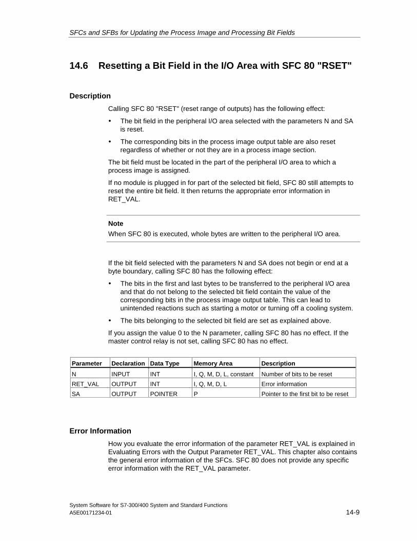
SFCs and SFBs for Updating the Process Image and Processing Bit Fields
System Software for S7-300/400 System and Standard FunctionsA5E00171234-01 14-9
14.6 Resetting a Bit Field in the I/O Area with SFC 80 "RSET"
Description
Calling SFC 80 "RSET" (reset range of outputs) has the following effect:
• The bit field in the peripheral I/O area selected with the parameters N and SAis reset.
• The corresponding bits in the process image output table are also resetregardless of whether or not they are in a process image section.
The bit field must be located in the part of the peripheral I/O area to which aprocess image is assigned.
If no module is plugged in for part of the selected bit field, SFC 80 still attempts toreset the entire bit field. It then returns the appropriate error information inRET_VAL.
Note
When SFC 80 is executed, whole bytes are written to the peripheral I/O area.
If the bit field selected with the parameters N and SA does not begin or end at abyte boundary, calling SFC 80 has the following effect:
• The bits in the first and last bytes to be transferred to the peripheral I/O areaand that do not belong to the selected bit field contain the value of thecorresponding bits in the process image output table. This can lead tounintended reactions such as starting a motor or turning off a cooling system.
• The bits belonging to the selected bit field are set as explained above.
If you assign the value 0 to the N parameter, calling SFC 80 has no effect. If themaster control relay is not set, calling SFC 80 has no effect.
Parameter Declaration Data Type Memory Area Description
N INPUT INT I, Q, M, D, L, constant Number of bits to be reset
RET_VAL OUTPUT INT I, Q, M, D, L Error information
SA OUTPUT POINTER P Pointer to the first bit to be reset
Error Information
How you evaluate the error information of the parameter RET_VAL is explained inEvaluating Errors with the Output Parameter RET_VAL. This chapter also containsthe general error information of the SFCs. SFC 80 does not provide any specificerror information with the RET_VAL parameter.
SFCs and SFBs for Updating the Process Image and Processing Bit Fields
System Software for S7-300/400 System and Standard Functions14-10 A5E00171234-01
14.7 Implementing a Sequencer with SFB 32 "DRUM"
Description
SFB 32 "DRUM" implements a sequencer with a maximum of 16 steps. Youspecify the number of the first step with the DSP parameter and the number of thelast step with the LST_STEP parameter.
During each step, all 16 output bits OUT0 to OUT15 and the output parameterOUT_WORD (in which the output bits are collected together) are written. An outputbit is assigned either the corresponding bit of the OUT_VAL array that you specifyor the output bit is assigned the value of the corresponding output bit of theprevious step. Which value is assigned depends on how you set the mask bits inthe S_MASK parameter (see following table).
SFB 32 "DRUM" switches to the next step when there is a rising edge at the JOGinput compared with the previous SFB call. If the SFB has already reached the laststep, a rising edge at JOG sets the variables Q and EOD; DCC has the value 0;and the SFB remains in the last step until 1 is set at the RESET input.
You can also assign parameters so that switching to the next step is timedependent. To do this, you must set the DRUM_EN parameter to 1. The sequencerthen switches to the next step when:
• The event bit EVENT is set for the current step and
• The time programmed for the current step has expired.
This time is the product of the DTBP time base and the time factor valid for thecurrent step (from the S_PRESET array)
Note
The execution time remaining in the current step (DCC) is only reduced when thecorresponding event bit EVENT is set.
If a 1 is set at the RESET input when the SFB is called, the sequencer goes to thestep you assigned to the DSP input.
Note
If you set a 1 for DRUM_EN, you can achieve the following special situation:
• Purely time-dependent enabling of the steps by selecting EVENT = 1 whereDSP < i < LST_STEP.
• Purely event-dependent enabling of the steps using the event bits EVENT bysetting 0 at DTBP.
You can also move on to the next step in the sequencer at any time (even ifDRUM_EN=1) via the JOG input.
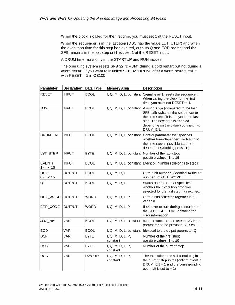
SFCs and SFBs for Updating the Process Image and Processing Bit Fields
System Software for S7-300/400 System and Standard FunctionsA5E00171234-01 14-11
When the block is called for the first time, you must set 1 at the RESET input.
When the sequencer is in the last step (DSC has the value LST_STEP) and whenthe execution time for this step has expired, outputs Q and EOD are set and theSFB remains in the last step until you set 1 at the RESET input.
A DRUM timer runs only in the STARTUP and RUN modes.
The operating system resets SFB 32 "DRUM" during a cold restart but not during awarm restart. If you want to initialize SFB 32 "DRUM" after a warm restart, call itwith RESET = 1 in OB100.
Parameter Declaration Data Type Memory Area Description
RESET INPUT BOOL I, Q, M, D, L, constant Signal level 1 resets the sequencer.When calling the block for the firsttime, you must set RESET to 1.
JOG INPUT BOOL I, Q, M, D, L, constant A rising edge (compared to the lastSFB call) switches the sequencer tothe next step if it is not yet in the laststep. The next step is enableddepending on the value you assign toDRUM_EN.
DRUM_EN INPUT BOOL I, Q, M, D, L, constant Control parameter that specifieswhether time-dependent switching tothe next step is possible (1: time-dependent switching possible)
LST_STEP INPUT BYTE I, Q, M, D, L, constant Number of the last step;possible values: 1 to 16
EVENTi,1 < i < 16
INPUT BOOL I, Q, M, D, L, constant Event bit number i (belongs to step i)
OUTj,0 < j < 15
OUTPUT BOOL I, Q, M, D, L Output bit number j (identical to the bitnumber j of OUT_WORD)
Q OUTPUT BOOL I, Q, M, D, L Status parameter that specifieswhether the execution time youselected for the last step has expired.
OUT_WORD OUTPUT WORD I, Q, M, D, L, P Output bits collected together in avariable
ERR_CODE OUTPUT WORD I, Q, M, D, L, P If an error occurs during execution ofthe SFB, ERR_CODE contains theerror information.
JOG_HIS VAR BOOL I, Q, M, D, L, constant (No relevance for the user: JOG inputparameter of the previous SFB call)
EOD VAR BOOL I, Q, M, D, L, constant Identical to the output parameter Q
DSP VAR BYTE I, Q, M, D, L, P,constant
Number of the first step;possible values: 1 to 16
DSC VAR BYTE I, Q, M, D, L, P,constant
Number of the current step
DCC VAR DWORD I, Q, M, D, L, P,constant
The execution time still remaining inthe current step in ms (only relevant ifDRUM_EN = 1 and the correspondingevent bit is set to = 1)
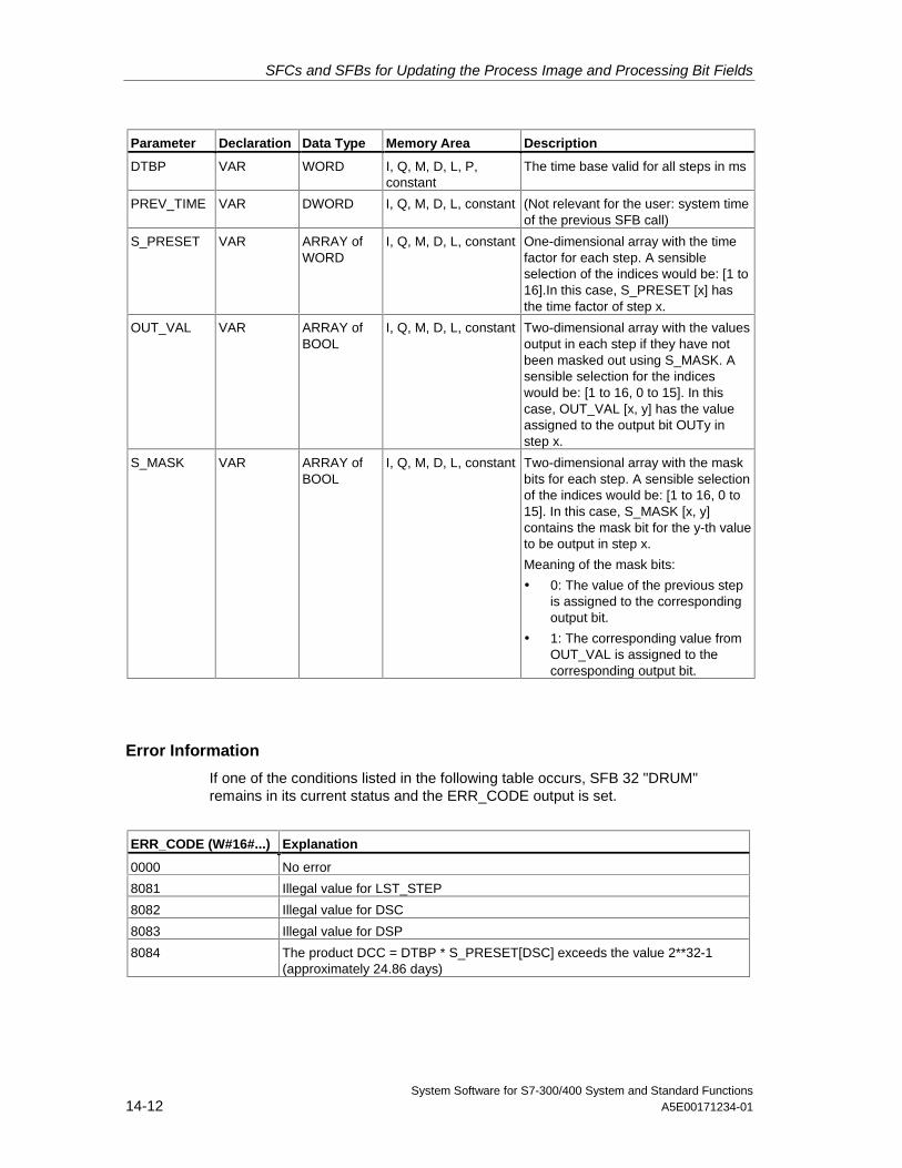
SFCs and SFBs for Updating the Process Image and Processing Bit Fields
System Software for S7-300/400 System and Standard Functions14-12 A5E00171234-01
Parameter Declaration Data Type Memory Area Description
DTBP VAR WORD I, Q, M, D, L, P,constant
The time base valid for all steps in ms
PREV_TIME VAR DWORD I, Q, M, D, L, constant (Not relevant for the user: system timeof the previous SFB call)
S_PRESET VAR ARRAY ofWORD
I, Q, M, D, L, constant One-dimensional array with the timefactor for each step. A sensibleselection of the indices would be: [1 to16].In this case, S_PRESET [x] hasthe time factor of step x.
OUT_VAL VAR ARRAY ofBOOL
I, Q, M, D, L, constant Two-dimensional array with the valuesoutput in each step if they have notbeen masked out using S_MASK. Asensible selection for the indiceswould be: [1 to 16, 0 to 15]. In thiscase, OUT_VAL [x, y] has the valueassigned to the output bit OUTy instep x.
S_MASK VAR ARRAY ofBOOL
I, Q, M, D, L, constant Two-dimensional array with the maskbits for each step. A sensible selectionof the indices would be: [1 to 16, 0 to15]. In this case, S_MASK [x, y]contains the mask bit for the y-th valueto be output in step x.
Meaning of the mask bits:
• 0: The value of the previous stepis assigned to the correspondingoutput bit.
• 1: The corresponding value fromOUT_VAL is assigned to thecorresponding output bit.
Error Information
If one of the conditions listed in the following table occurs, SFB 32 "DRUM"remains in its current status and the ERR_CODE output is set.
ERR_CODE (W#16#...) Explanation
0000 No error
8081 Illegal value for LST_STEP
8082 Illegal value for DSC
8083 Illegal value for DSP
8084 The product DCC = DTBP * S_PRESET[DSC] exceeds the value 2**32-1(approximately 24.86 days)
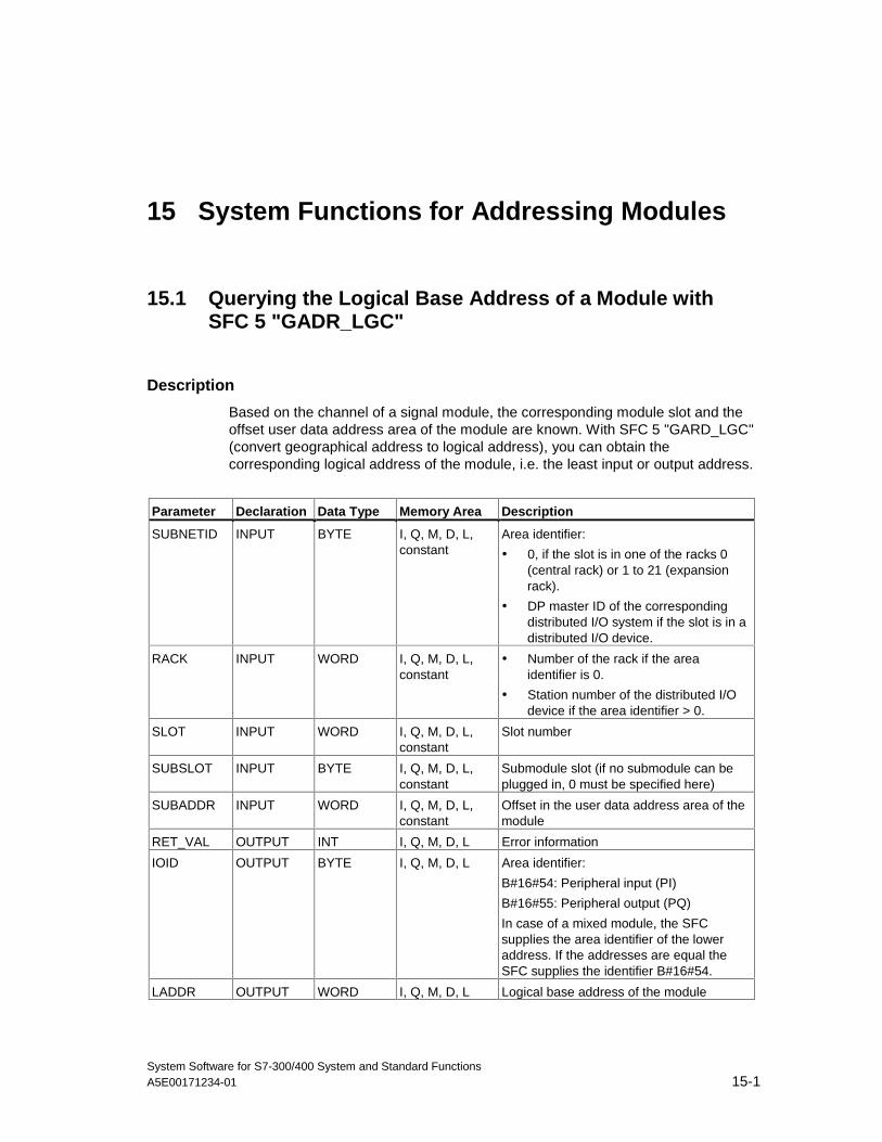
System Software for S7-300/400 System and Standard FunctionsA5E00171234-01 15-1
15 System Functions for Addressing Modules
15.1 Querying the Logical Base Address of a Module withSFC 5 "GADR_LGC"
Description
Based on the channel of a signal module, the corresponding module slot and theoffset user data address area of the module are known. With SFC 5 "GARD_LGC"(convert geographical address to logical address), you can obtain thecorresponding logical address of the module, i.e. the least input or output address.
Parameter Declaration Data Type Memory Area Description
SUBNETID INPUT BYTE I, Q, M, D, L,constant
Area identifier:
• 0, if the slot is in one of the racks 0(central rack) or 1 to 21 (expansionrack).
• DP master ID of the correspondingdistributed I/O system if the slot is in adistributed I/O device.
RACK INPUT WORD I, Q, M, D, L,constant
• Number of the rack if the areaidentifier is 0.
• Station number of the distributed I/Odevice if the area identifier > 0.
SLOT INPUT WORD I, Q, M, D, L,constant
Slot number
SUBSLOT INPUT BYTE I, Q, M, D, L,constant
Submodule slot (if no submodule can beplugged in, 0 must be specified here)
SUBADDR INPUT WORD I, Q, M, D, L,constant
Offset in the user data address area of themodule
RET_VAL OUTPUT INT I, Q, M, D, L Error information
IOID OUTPUT BYTE I, Q, M, D, L Area identifier:
B#16#54: Peripheral input (PI)
B#16#55: Peripheral output (PQ)
In case of a mixed module, the SFCsupplies the area identifier of the loweraddress. If the addresses are equal theSFC supplies the identifier B#16#54.
LADDR OUTPUT WORD I, Q, M, D, L Logical base address of the module
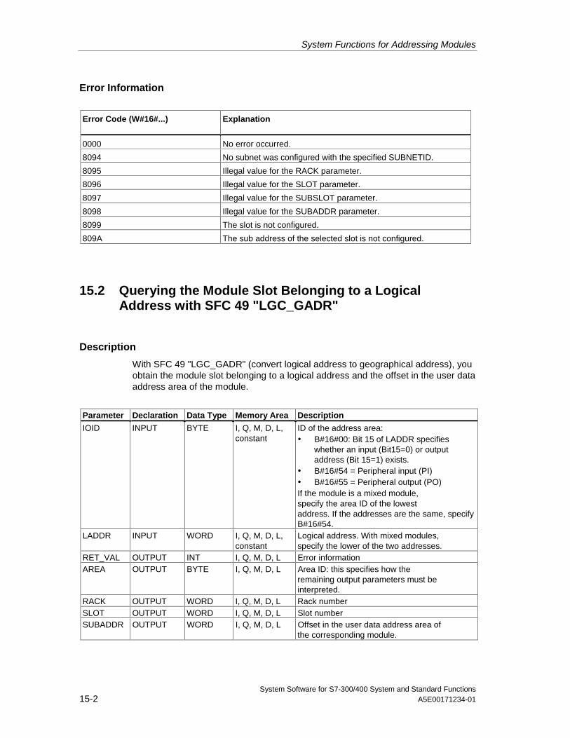
System Functions for Addressing Modules
System Software for S7-300/400 System and Standard Functions15-2 A5E00171234-01
Error Information
Error Code (W#16#...) Explanation
0000 No error occurred.
8094 No subnet was configured with the specified SUBNETID.
8095 Illegal value for the RACK parameter.
8096 Illegal value for the SLOT parameter.
8097 Illegal value for the SUBSLOT parameter.
8098 Illegal value for the SUBADDR parameter.
8099 The slot is not configured.
809A The sub address of the selected slot is not configured.
15.2 Querying the Module Slot Belonging to a LogicalAddress with SFC 49 "LGC_GADR"
Description
With SFC 49 "LGC_GADR" (convert logical address to geographical address), youobtain the module slot belonging to a logical address and the offset in the user dataaddress area of the module.
Parameter Declaration Data Type Memory Area Description
IOID INPUT BYTE I, Q, M, D, L,constant
ID of the address area:• B#16#00: Bit 15 of LADDR specifies
whether an input (Bit15=0) or outputaddress (Bit 15=1) exists.
• B#16#54 = Peripheral input (PI)• B#16#55 = Peripheral output (PO)If the module is a mixed module,specify the area ID of the lowestaddress. If the addresses are the same, specifyB#16#54.
LADDR INPUT WORD I, Q, M, D, L,constant
Logical address. With mixed modules,specify the lower of the two addresses.
RET_VAL OUTPUT INT I, Q, M, D, L Error informationAREA OUTPUT BYTE I, Q, M, D, L Area ID: this specifies how the
remaining output parameters must beinterpreted.
RACK OUTPUT WORD I, Q, M, D, L Rack numberSLOT OUTPUT WORD I, Q, M, D, L Slot numberSUBADDR OUTPUT WORD I, Q, M, D, L Offset in the user data address area of
the corresponding module.
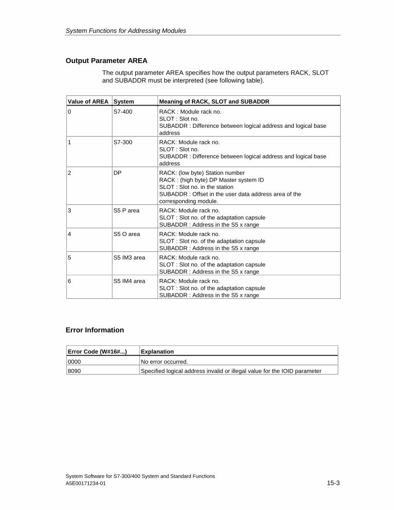
System Functions for Addressing Modules
System Software for S7-300/400 System and Standard FunctionsA5E00171234-01 15-3
Output Parameter AREA
The output parameter AREA specifies how the output parameters RACK, SLOTand SUBADDR must be interpreted (see following table).
Value of AREA System Meaning of RACK, SLOT and SUBADDR
0 S7-400 RACK : Module rack no.SLOT : Slot no.SUBADDR : Difference between logical address and logical baseaddress
1 S7-300 RACK: Module rack no.SLOT : Slot no.SUBADDR : Difference between logical address and logical baseaddress
2 DP RACK: (low byte) Station numberRACK : (high byte) DP Master system IDSLOT : Slot no. in the stationSUBADDR : Offset in the user data address area of thecorresponding module.
3 S5 P area RACK: Module rack no.SLOT : Slot no. of the adaptation capsuleSUBADDR : Address in the S5 x range
4 S5 O area RACK: Module rack no.SLOT : Slot no. of the adaptation capsuleSUBADDR : Address in the S5 x range
5 S5 IM3 area RACK: Module rack no.SLOT : Slot no. of the adaptation capsuleSUBADDR : Address in the S5 x range
6 S5 IM4 area RACK: Module rack no.SLOT : Slot no. of the adaptation capsuleSUBADDR : Address in the S5 x range
Error Information
Error Code (W#16#...) Explanation
0000 No error occurred.
8090 Specified logical address invalid or illegal value for the IOID parameter
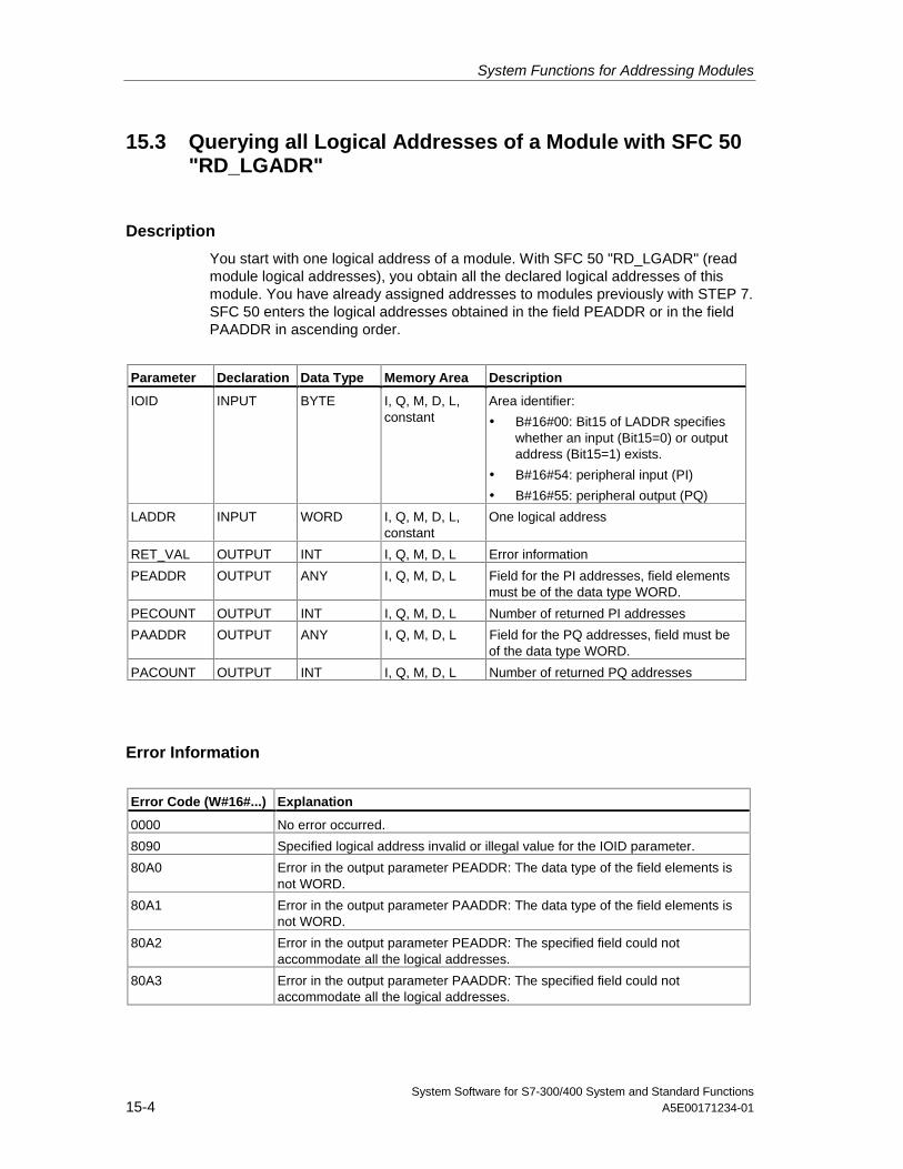
System Functions for Addressing Modules
System Software for S7-300/400 System and Standard Functions15-4 A5E00171234-01
15.3 Querying all Logical Addresses of a Module with SFC 50"RD_LGADR"
Description
You start with one logical address of a module. With SFC 50 "RD_LGADR" (readmodule logical addresses), you obtain all the declared logical addresses of thismodule. You have already assigned addresses to modules previously with STEP 7.SFC 50 enters the logical addresses obtained in the field PEADDR or in the fieldPAADDR in ascending order.
Parameter Declaration Data Type Memory Area Description
IOID INPUT BYTE I, Q, M, D, L,constant
Area identifier:
• B#16#00: Bit15 of LADDR specifieswhether an input (Bit15=0) or outputaddress (Bit15=1) exists.
• B#16#54: peripheral input (PI)
• B#16#55: peripheral output (PQ)
LADDR INPUT WORD I, Q, M, D, L,constant
One logical address
RET_VAL OUTPUT INT I, Q, M, D, L Error information
PEADDR OUTPUT ANY I, Q, M, D, L Field for the PI addresses, field elementsmust be of the data type WORD.
PECOUNT OUTPUT INT I, Q, M, D, L Number of returned PI addresses
PAADDR OUTPUT ANY I, Q, M, D, L Field for the PQ addresses, field must beof the data type WORD.
PACOUNT OUTPUT INT I, Q, M, D, L Number of returned PQ addresses
Error Information
Error Code (W#16#...) Explanation
0000 No error occurred.
8090 Specified logical address invalid or illegal value for the IOID parameter.
80A0 Error in the output parameter PEADDR: The data type of the field elements isnot WORD.
80A1 Error in the output parameter PAADDR: The data type of the field elements isnot WORD.
80A2 Error in the output parameter PEADDR: The specified field could notaccommodate all the logical addresses.
80A3 Error in the output parameter PAADDR: The specified field could notaccommodate all the logical addresses.
System Software for S7-300/400 System and Standard FunctionsA5E00171234-01 16-1
16 SFCs for Distributed I/Os
16.1 Triggering a Hardware Interrupt on the DP Master withSFC 7 "DP_PRAL"
Description
With SFC 7 "DP_PRAL," you trigger a hardware interrupt on the DP master fromthe user program of an intelligent slave. This interrupt starts OB40 on the DPmaster.
Using the input parameter AL_INFO, you can identify the cause of the hardwareinterrupt. This interrupt identifier is transferred to the DP master and you canevaluate the identifier in OB40 (variable OB40_POINT_ADDR).
The requested hardware interrupt is uniquely specified by the input parametersIOID and LADDR. For each configured address area in the transfer memory, youcan trigger exactly one hardware interrupt at any time.
How the SFC Operates
SFC 7 "DP_PRAL" operates asynchronously, in other words, it is executed overseveral SFC calls. You start the hardware interrupt request by calling SFC 7 withREQ=1.
The status of the job is indicated by the output parameters RET_VAL and BUSY,see Meaning of the Parameters REQ, RET_VAL and BUSY with AsynchronousSFCs. The job is completed when execution of OB40 is completed on the DPmaster.
Note
If you operate the DP slave as a standard slave, the job is completed as soon asthe diagnostic frame is obtained by the DP master.
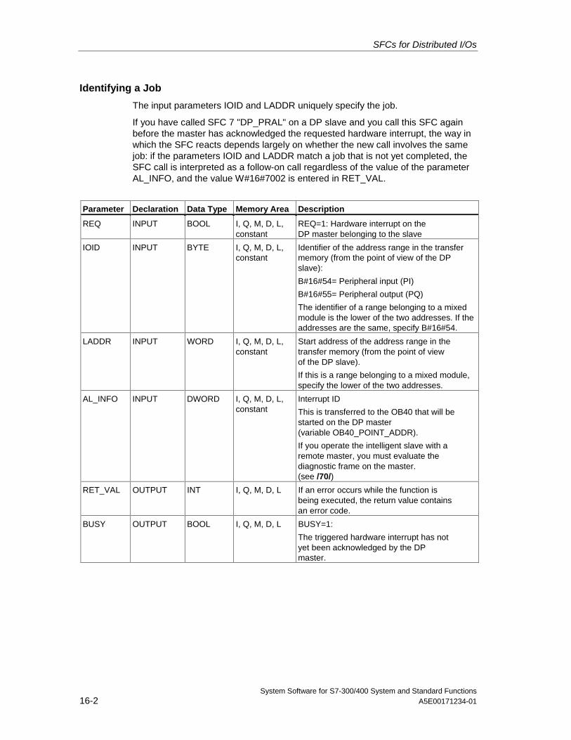
SFCs for Distributed I/Os
System Software for S7-300/400 System and Standard Functions16-2 A5E00171234-01
Identifying a Job
The input parameters IOID and LADDR uniquely specify the job.
If you have called SFC 7 "DP_PRAL" on a DP slave and you call this SFC againbefore the master has acknowledged the requested hardware interrupt, the way inwhich the SFC reacts depends largely on whether the new call involves the samejob: if the parameters IOID and LADDR match a job that is not yet completed, theSFC call is interpreted as a follow-on call regardless of the value of the parameterAL_INFO, and the value W#16#7002 is entered in RET_VAL.
Parameter Declaration Data Type Memory Area Description
REQ INPUT BOOL I, Q, M, D, L,constant
REQ=1: Hardware interrupt on theDP master belonging to the slave
IOID INPUT BYTE I, Q, M, D, L,constant
Identifier of the address range in the transfermemory (from the point of view of the DPslave):
B#16#54= Peripheral input (PI)
B#16#55= Peripheral output (PQ)
The identifier of a range belonging to a mixedmodule is the lower of the two addresses. If theaddresses are the same, specify B#16#54.
LADDR INPUT WORD I, Q, M, D, L,constant
Start address of the address range in thetransfer memory (from the point of viewof the DP slave).
If this is a range belonging to a mixed module,specify the lower of the two addresses.
AL_INFO INPUT DWORD I, Q, M, D, L,constant
Interrupt ID
This is transferred to the OB40 that will bestarted on the DP master(variable OB40_POINT_ADDR).
If you operate the intelligent slave with aremote master, you must evaluate thediagnostic frame on the master.(see /70/)
RET_VAL OUTPUT INT I, Q, M, D, L If an error occurs while the function isbeing executed, the return value containsan error code.
BUSY OUTPUT BOOL I, Q, M, D, L BUSY=1:
The triggered hardware interrupt has notyet been acknowledged by the DPmaster.
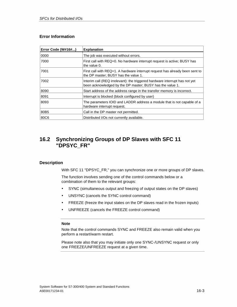
SFCs for Distributed I/Os
System Software for S7-300/400 System and Standard FunctionsA5E00171234-01 16-3
Error Information
Error Code (W#16#...) Explanation
0000 The job was executed without errors.
7000 First call with REQ=0. No hardware interrupt request is active; BUSY hasthe value 0.
7001 First call with REQ=1. A hardware interrupt request has already been sent tothe DP master; BUSY has the value 1.
7002 Interim call (REQ irrelevant): the triggered hardware interrupt has not yetbeen acknowledged by the DP master; BUSY has the value 1.
8090 Start address of the address range in the transfer memory is incorrect.
8091 Interrupt is blocked (block configured by user)
8093 The parameters IOID and LADDR address a module that is not capable of ahardware interrupt request.
80B5 Call in the DP master not permitted.
80C6 Distributed I/Os not currently available.
16.2 Synchronizing Groups of DP Slaves with SFC 11"DPSYC_FR"
Description
With SFC 11 "DPSYC_FR," you can synchronize one or more groups of DP slaves.
The function involves sending one of the control commands below or acombination of them to the relevant groups:
• SYNC (simultaneous output and freezing of output states on the DP slaves)
• UNSYNC (cancels the SYNC control command)
• FREEZE (freeze the input states on the DP slaves read in the frozen inputs)
• UNFREEZE (cancels the FREEZE control command)
Note
Note that the control commands SYNC and FREEZE also remain valid when youperform a restart/warm restart.
Please note also that you may initiate only one SYNC-/UNSYNC request or onlyone FREEZE/UNFREEZE request at a given time.
SFCs for Distributed I/Os
System Software for S7-300/400 System and Standard Functions16-4 A5E00171234-01
Requirements
Before you send the control commands listed above, you must assign the DPslaves to groups using STEP 7 (see /231/). You must know which DP slave isassigned to which group with which number and know the reactions of the variousgroups to SYNC/FREEZE.
How the SFC Operates
SFC 11 "DPSYC_FR" is an asynchronous SFC; in other words, its execution takesseveral SFC calls. You start the job by calling SFC 11 with REQ=1.
The status of the job is indicated by the output parameters RET_VAL and BUSY,also refer to Meaning of the Parameters REQ, RET_VAL and BUSY withAsynchronous SFCs.
Identifying a Job
If you have triggered a SYNC/FREEZE job and called SFC 11 again before the firstjob was completed, the response of the SFC depends on whether the new call isfor the same job. If the input parameters LADDR, GROUP and MODE match, theSFC call is interpreted as a follow-on call.
Writing Outputs of DP Modules
The writing of outputs of DP modules is triggered as follows:
• By transfer commands to the DP I/Os,
• By writing the process image output table to the modules (by the operatingsystem at the end of OB1 or by calling SFC 27 "UPDAT_PO"),
• By calling SFC 15 "DPWR_DAT."
In normal operation, the DP master transfers the output bytes cyclically (within thecycle of the PROFIBUS DP bus) to the outputs of the DP slaves.
If you want to have certain output data (possibly distributed on several slaves)applied to the outputs to the process at exactly the same time, you can send theSYNC command to the relevant DP master using SFC 11 "DPSYC_FR."
SFCs for Distributed I/Os
System Software for S7-300/400 System and Standard FunctionsA5E00171234-01 16-5
What are the Effects of SYNC?
With the SYNC control command, the DP slaves of the selected groups areswitched to the Sync mode. In other words, the DP master transfers the currentoutput data and instructs the DP slaves involved to freeze their outputs. With thefollowing output frames, the DP slaves enter the output data in an internal bufferand the state of the outputs remains unchanged.
Following each SYNC control command, the DP slaves of the selected groupsapply the output data of their internal buffer to the outputs to the process.
The outputs are only updated cyclically again when you send the UNSYNC controlcommand using SFC 11 "DPSYC_FR."
Note
If the DP slaves of the selected group(s) are not currently connected to the networkor have failed when the control command has been sent, they will not be switchedto SYNC mode. This information will not be communicated in the return value ofthe SFC.
Reading Input Data of DP Modules
The input data of the DP modules are read as follows:
• Using load commands to the DP I/Os,
• When the process image input table is updated (by the operating system at thestart of OB1 or by calling SFC 26 "UPDAT_PI"),
• By calling SFC 14 "DPRD_DAT."
In normal operation, the DP master receives this input data cyclically (within thecycle of the PROFIBUS DP bus) from its DP slaves and makes them available tothe CPU.
If you want to have certain input data (possibly distributed on several slaves) to beread from the process at exactly the same time, send the FREEZE controlcommand to the relevant DP master using SFC 11 "DPSYC_FR."
SFCs for Distributed I/Os
System Software for S7-300/400 System and Standard Functions16-6 A5E00171234-01
What are the Effects of FREEZE?
With the FREEZE control command, the DP slaves involved are switched to theFreeze mode, in other words the DP master instructs the DP slaves to freeze thecurrent state of the inputs. It then transfers the frozen data to the input area of theCPU.
Following each FREEZE control command, the DP slaves freeze the state of theirinputs again.
The DP master only receives the current state of the inputs cyclically again afteryou have sent the UNFREEZE control command with SFC 11 "DPSYC_FR."
Note
If the DP slaves of the selected group(s) are not currently connected to the networkor have failed when the control command has been sent, they will not be switchedto FREEZE mode. This information will not be communicated in the return value ofthe SFC.
Data Consistency
Because SFC 11 "DPSYC_FR" functions are acyclic and can be interrupted byhigher priority classes, you should make sure that the process images areconsistent with the actual inputs and outputs when using SFC 11 "DPSYC_FR".
This is guaranteed if you keep to the following consistency rules:
• Define suitable process image sections for the "SYNC outputs" and the"FREEZE inputs" (only possible on the S7-400). Call SFC 27 "UPDAT_PO"immediately before the first call for a SYNC job. Call SFC 26 "UPDAT_PI"immediately after the last call for a FREEZE job.
• As an alternative: Use only direct I/O access for outputs involved in a SYNCjob and for inputs involved in a FREEZE job. You must not write to theseoutputs when a SYNC job is active and not read these inputs when a FREEZEjob is active.
Using SFC 15 and SFC 14
If you use SFC 15 "DPWR_DAT," this SFC must be completed before you send aSYNC job to the outputs involved.
If you use SFC 14 "DPRD_DAT," this SFC must be completed before you send aFREEZE job to the inputs involved.
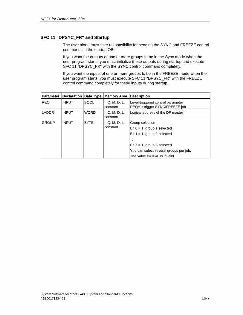
SFCs for Distributed I/Os
System Software for S7-300/400 System and Standard FunctionsA5E00171234-01 16-7
SFC 11 "DPSYC_FR" and Startup
The user alone must take responsibility for sending the SYNC and FREEZE controlcommands in the startup OBs.
If you want the outputs of one or more groups to be in the Sync mode when theuser program starts, you must initialize these outputs during startup and executeSFC 11 "DPSYC_FR" with the SYNC control command completely.
If you want the inputs of one or more groups to be in the FREEZE mode when theuser program starts, you must execute SFC 11 "DPSYC_FR" with the FREEZEcontrol command completely for these inputs during startup.
Parameter Declaration Data Type Memory Area Description
REQ INPUT BOOL I, Q, M, D, L,constant
Level-triggered control parameterREQ=1: trigger SYNC/FREEZE job
LADDR INPUT WORD I, Q, M, D, L,constant
Logical address of the DP master
GROUP INPUT BYTE I, Q, M, D, L,constant
Group selection
Bit 0 = 1: group 1 selected
Bit 1 = 1: group 2 selected
:
Bit 7 = 1: group 8 selected
You can select several groups per job.
The value B#16#0 is invalid.
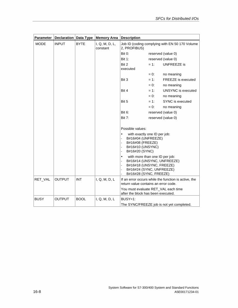
SFCs for Distributed I/Os
System Software for S7-300/400 System and Standard Functions16-8 A5E00171234-01
Parameter Declaration Data Type Memory Area Description
MODE INPUT BYTE I, Q, M, D, L,constant
Job ID (coding complying with EN 50 170 Volume2, PROFIBUS)
Bit 0: reserved (value 0)
Bit 1: reserved (value 0)
Bit 2 = 1: UNFREEZE isexecuted
= 0: no meaning
Bit 3 = 1: FREEZE is executed
= 0: no meaning
Bit 4 = 1: UNSYNC is executed
= 0: no meaning
Bit 5 = 1: SYNC is executed
= 0: no meaning
Bit 6: reserved (value 0)
Bit 7: reserved (value 0)
Possible values:
• with exactly one ID per job:- B#16#04 (UNFREEZE)- B#16#08 (FREEZE)- B#16#10 (UNSYNC)- B#16#20 (SYNC)
• with more than one ID per job:- B#16#14 (UNSYNC, UNFREEZE)- B#16#18 (UNSYNC, FREEZE)- B#16#24 (SYNC, UNFREEZE)- B#16#28 (SYNC, FREEZE)
RET_VAL OUTPUT INT I, Q, M, D, L If an error occurs while the function is active, thereturn value contains an error code.
You must evaluate RET_VAL each timeafter the block has been executed.
BUSY OUTPUT BOOL I, Q, M, D, L BUSY=1:
The SYNC/FREEZE job is not yet completed.
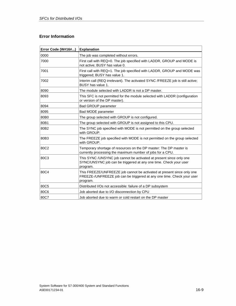
SFCs for Distributed I/Os
System Software for S7-300/400 System and Standard FunctionsA5E00171234-01 16-9
Error Information
Error Code (W#16#...) Explanation
0000 The job was completed without errors.
7000 First call with REQ=0. The job specified with LADDR, GROUP and MODE isnot active; BUSY has value 0.
7001 First call with REQ=1. The job specified with LADDR, GROUP and MODE wastriggered; BUSY has value 1.
7002 Interim call (REQ irrelevant). The activated SYNC /FREEZE job is still active;BUSY has value 1.
8090 The module selected with LADDR is not a DP master.
8093 This SFC is not permitted for the module selected with LADDR (configurationor version of the DP master).
8094 Bad GROUP parameter
8095 Bad MODE parameter
80B0 The group selected with GROUP is not configured.
80B1 The group selected with GROUP is not assigned to this CPU.
80B2 The SYNC job specified with MODE is not permitted on the group selectedwith GROUP.
80B3 The FREEZE job specified with MODE is not permitted on the group selectedwith GROUP.
80C2 Temporary shortage of resources on the DP master: The DP master iscurrently processing the maximum number of jobs for a CPU.
80C3 This SYNC /UNSYNC job cannot be activated at present since only oneSYNC/UNSYNC job can be triggered at any one time. Check your userprogram.
80C4 This FREEZE/UNFREEZE job cannot be activated at present since only oneFREEZE-/UNFREEZE job can be triggered at any one time. Check your userprogram.
80C5 Distributed I/Os not accessible: failure of a DP subsystem
80C6 Job aborted due to I/O disconnection by CPU
80C7 Job aborted due to warm or cold restart on the DP master
SFCs for Distributed I/Os
System Software for S7-300/400 System and Standard Functions16-10 A5E00171234-01
16.3 Deactivating and Activating DP Slaves with SFC 12"D_ACT_DP"
DescriptionWith SFC 12 "D_ACT_DP, you can specifically deactivate and reactivateconfigured DP slaves. In addition, you can determine whether each assigned DPslave is currently activated or deactivated.
SFC 12 cannot be used on PROFIBUS PA field devices which are connected by aDP/PA link to a DP master system.
Note
As long as any SFC 12 job is busy you cannot download a modified configurationfrom your PG to the CPU (during a CiR process).The CPU rejects initiation of an SFC 12 request when it receives the download of amodified configuration during a CiR process.
Purpose
If you configure DP slaves in a CPU which are not actually present or not currentlyrequired, the CPU will nevertheless continue to access these DP slaves at regularintervals. After the slaves are deactivated, further CPU accessing will stop. In thisway, the fastest possible DP bus cycle can be achieved and the correspondingerror events no longer occur.
Application ExamplesFrom a machine builder’s point of view, there are numerous device optionspossible in series production of machines. However, each delivered machineincludes only one combination of selected options.
Every one of these possible machine options is configured as a DP slave by themanufacturer in order to create and maintain a common user program having allpossible options. With SFC 12, you can deactivate all DP slaves which are notpresent at machine startup.
A similar situation exists for machine tools having numerous tooling optionsavailable but actually using only a few of them at any given time. These tools areimplemented as DP slaves. With SFC 12, the user program activates the toolscurrently needed and deactivates those required later.
SFCs for Distributed I/Os
System Software for S7-300/400 System and Standard FunctionsA5E00171234-01 16-11
How the SFC OperatesSFC 12 ”D_ACT_DP” operates asynchronously, in other words, it is executed overseveral SFC calls. You start the request by calling SFC 12 with REQ=1.
The status of the job is indicated by the output parameters RET_VAL and BUSY;see also Section 2.2 of the Ref. HB “System Software for S7–300/400 System /-and Standard Functions.”
Identifying a Job
If you have started a deactivation or activation job and you call SFC 12 againbefore the job is completed, the way in which the SFC reacts depends largely onwhether the new call involves the same job: If the parameter LADDR matches, theSFC call is interpreted as a follow-on call.
Deactivating DP SlavesWhen you deactivate a DP slave with SFC 12, its process outputs are set to theconfigured substitute values or to 0 (secure state). The assigned DP master doesnot continue to address this DP slave. Deactivated DP slaves are not identified asfaulty or missing by the error LEDs on the DP master or CPU.
The process image of the inputs of deactivated DP slaves is updated with 0, that is,it is handled just as for failed DP slaves.
If you are using your program to directly access the user data of a previouslydeactivated DP slave, the I/O access error OB (OB 122) is called, and thecorresponding start event is entered in the diagnostic buffer. If you attempt toaccess a deactivated DP slave with SFC (i.e. SFC 59 “RD_REC”), you receive theerror information in RET_VAL as for an unavailable DP slave.
Deactivating a DP slave does not start the program error OB (OB 85), even if itsinputs or outputs belong to the system-side process image to be updated. No entryis made in the diagnostic buffer.
Deactivating a DP slave does not start the rack failure OB (OB 86), and theoperating system also does not make an entry in the diagnostic buffer.
If a DP station fails after you have deactivated it with SFC 12, the operating systemdoes not detect the failure. As a result, there is no subsequent start of OB86 ordiagnostic buffer entry. The station failure is detected only after the station hasbeen reactivated and indicated in RET_VAL.
If you wish to deactivate DP slaves functioning as transmitters in crosscommunication, we recommend that you first deactivate the receivers (listeners)that detect which input data the transmitter is transferring to its DP master.Deactivate the transmitter only after you have performed this step.
SFCs for Distributed I/Os
System Software for S7-300/400 System and Standard Functions16-12 A5E00171234-01
Activating DP SlavesWhen you reactivate a DP slave with SFC 12, it is configured and assignedparameters by the designated DP master (as with the return of a failed station).This activation is completed when the slave is able to transfer user data.
Activating a DP slave does not start the program error OB (OB85), even if its inputsor outputs belong to the system-side process image to be updated. An entry in thediagnostic buffer is also not made.
Activating a DP slave does not start the rack failure OB (OB86), and the operatingsystem also does not make an entry in the diagnostic buffer.
If you attempt to use SFC 12 to activate a slave which has been deactivated and isphysically separated from the DP bus, the LED "DP-BUSF" on the CPU will blinkfor about one minute. After this monitoring period has expired, the SFC returns theerror message W#16#80A2 and turns off the LED. The slave remains deactivated.If the slave is reconnected to the DP bus at a later time, it must be reactivated withSFC 12.
Note
Activating a DP slave may be time-consuming. Therefore, if you wish to cancel acurrent activation job, start SFC 12 again with the same value for LADDR andMODE = 2. Repeat the call of SFC 12 until successful cancellation of the activationis indicated by RET_VAL = 0.
If you wish to activate DP slaves which take part in the cross communication, werecommend that you first activate the transmitters and then the receivers(listeners).
CPU StartupDepending on the startup mode, the CPU operating system behaves as followsregarding DP slaves:
• In the startup modes cold and warm restart, slaves are activated automatically.
• In the hot restart mode, the slave activation status remains unchanged, that is,activated slaves remain activated and deactivated slaves remain deactivated.
After the CPU start-up, the CPU cyclically attempts to contact all configured andnot deactivated slaves that are either not present or not responding.
Note
The startup OBs do not support the call of SFC 12.
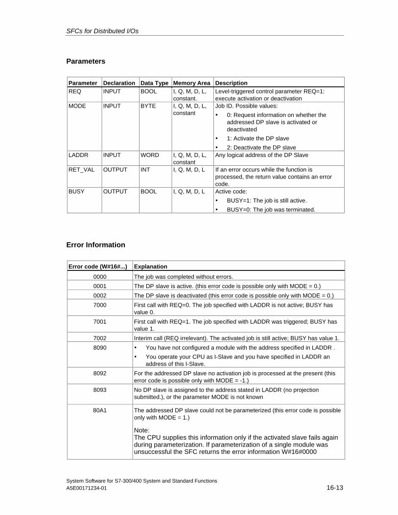
SFCs for Distributed I/Os
System Software for S7-300/400 System and Standard FunctionsA5E00171234-01 16-13
Parameters
Parameter Declaration Data Type Memory Area DescriptionREQ INPUT BOOL I, Q, M, D, L,
constant.Level-triggered control parameter REQ=1:execute activation or deactivation
MODE INPUT BYTE I, Q, M, D, L,constant
Job ID. Possible values:
• 0: Request information on whether theaddressed DP slave is activated ordeactivated
• 1: Activate the DP slave
• 2: Deactivate the DP slaveLADDR INPUT WORD I, Q, M, D, L,
constantAny logical address of the DP Slave
RET_VAL OUTPUT INT I, Q, M, D, L If an error occurs while the function isprocessed, the return value contains an errorcode.
BUSY OUTPUT BOOL I, Q, M, D, L Active code:
• BUSY=1: The job is still active.
• BUSY=0: The job was terminated.
Error Information
Error code (W#16#...) Explanation
0000 The job was completed without errors.
0001 The DP slave is active. (this error code is possible only with MODE = 0.)
0002 The DP slave is deactivated (this error code is possible only with MODE = 0.)
7000 First call with REQ=0. The job specified with LADDR is not active; BUSY hasvalue 0.
7001 First call with REQ=1. The job specified with LADDR was triggered; BUSY hasvalue 1.
7002 Interim call (REQ irrelevant). The activated job is still active; BUSY has value 1.
8090 • You have not configured a module with the address specified in LADDR .
• You operate your CPU as I-Slave and you have specified in LADDR anaddress of this I-Slave.
8092 For the addressed DP slave no activation job is processed at the present (thiserror code is possible only with MODE = -1.)
8093 No DP slave is assigned to the address stated in LADDR (no projectionsubmitted.), or the parameter MODE is not known
80A1 The addressed DP slave could not be parameterized (this error code is possibleonly with MODE = 1.)
Note:The CPU supplies this information only if the activated slave fails againduring parameterization. If parameterization of a single module wasunsuccessful the SFC returns the error information W#16#0000
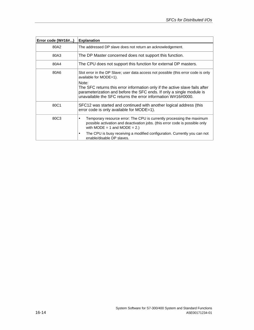
SFCs for Distributed I/Os
System Software for S7-300/400 System and Standard Functions16-14 A5E00171234-01
Error code (W#16#...) Explanation
80A2 The addressed DP slave does not return an acknowledgement.
80A3 The DP Master concerned does not support this function.
80A4 The CPU does not support this function for external DP masters.
80A6 Slot error in the DP Slave; user data access not possible (this error code is onlyavailable for MODE=1).
Note:The SFC returns this error information only if the active slave fails afterparameterization and before the SFC ends. If only a single module isunavailable the SFC returns the error information W#16#0000.
80C1 SFC12 was started and continued with another logical address (thiserror code is only available for MODE=1).
80C3 • Temporary resource error: The CPU is currently processing the maximumpossible activation and deactivation jobs. (this error code is possible onlywith MODE = 1 and MODE = 2.)
• The CPU is busy receiving a modified configuration. Currently you can notenable/disable DP slaves.
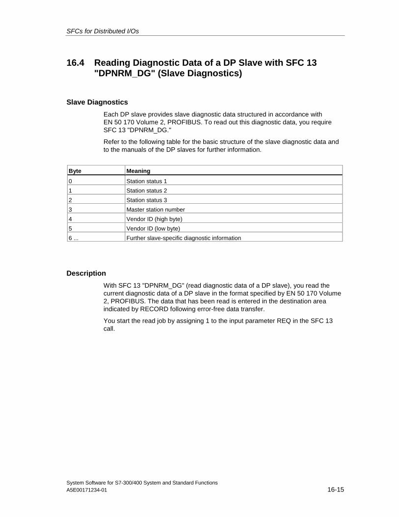
SFCs for Distributed I/Os
System Software for S7-300/400 System and Standard FunctionsA5E00171234-01 16-15
16.4 Reading Diagnostic Data of a DP Slave with SFC 13"DPNRM_DG" (Slave Diagnostics)
Slave Diagnostics
Each DP slave provides slave diagnostic data structured in accordance withEN 50 170 Volume 2, PROFIBUS. To read out this diagnostic data, you requireSFC 13 "DPNRM_DG."
Refer to the following table for the basic structure of the slave diagnostic data andto the manuals of the DP slaves for further information.
Byte Meaning
0 Station status 1
1 Station status 2
2 Station status 3
3 Master station number
4 Vendor ID (high byte)
5 Vendor ID (low byte)
6 ... Further slave-specific diagnostic information
Description
With SFC 13 "DPNRM_DG" (read diagnostic data of a DP slave), you read thecurrent diagnostic data of a DP slave in the format specified by EN 50 170 Volume2, PROFIBUS. The data that has been read is entered in the destination areaindicated by RECORD following error-free data transfer.
You start the read job by assigning 1 to the input parameter REQ in the SFC 13call.
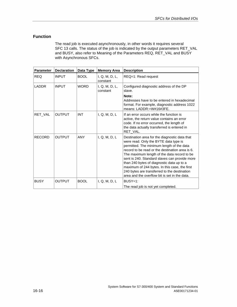
SFCs for Distributed I/Os
System Software for S7-300/400 System and Standard Functions16-16 A5E00171234-01
Function
The read job is executed asynchronously, in other words it requires severalSFC 13 calls. The status of the job is indicated by the output parameters RET_VALand BUSY, also refer to Meaning of the Parameters REQ, RET_VAL and BUSYwith Asynchronous SFCs.
Parameter Declaration Data Type Memory Area Description
REQ INPUT BOOL I, Q, M, D, L,constant
REQ=1: Read request
LADDR INPUT WORD I, Q, M, D, L,constant
Configured diagnostic address of the DPslave.
Note:Addresses have to be entered in hexadecimalformat. For example, diagnostic address 1022means: LADDR:=W#16#3FE.
RET_VAL OUTPUT INT I, Q, M, D, L If an error occurs while the function isactive, the return value contains an errorcode. If no error occurred, the length ofthe data actually transferred is entered inRET_VAL.
RECORD OUTPUT ANY I, Q, M, D, L Destination area for the diagnostic data thatwere read. Only the BYTE data type ispermitted. The minimum length of the datarecord to be read or the destination area is 6.The maximum length of the data record to besent is 240. Standard slaves can provide morethan 240 bytes of diagnostic data up to amaximum of 244 bytes. In this case, the first240 bytes are transferred to the destinationarea and the overflow bit is set in the data.
BUSY OUTPUT BOOL I, Q, M, D, L BUSY=1:
The read job is not yet completed.
SFCs for Distributed I/Os
System Software for S7-300/400 System and Standard FunctionsA5E00171234-01 16-17
Input Parameter RECORD
The CPU evaluates the actual length of the diagnostic data that were read asfollowing:
• If the length specified for RECORD is less than the number of data bytessupplied, the data are discarded and a corresponding error code is entered inRET_VAL.
• If the length specified for RECORD is greater than or equal to the number ofsupplied data bytes, the data are accepted in the destination area and theactual length is entered in RET_VAL as a positive value.
NoteYou must make sure that the actual parameters of RECORD match in all calls belonging toa job.
A job is uniquely identified by the LADDR input parameter.
Standard Slaves with more than 240 Bytes of Diagnostic Data
With standard slaves on which the number of standard diagnostic data is between241 and 244 bytes, note the following points:
• If the length specified for RECORD is less than 240 bytes, the data arediscarded and the corresponding error information is entered in RET_VAL.
• If the length specified for RECORD is greater than or equal to 240 bytes, thefirst 240 bytes of the standard diagnostic data are transferred to the destinationarea and the overflow bit is set in the data.
Output Parameter RET_VAL
• If an error occurs while the function is being executed, the return valuecontains an error code.
• If no error occurs during the data transfer, RET_VAL contains the length of thedata read in bytes as a positive number.
Note
The amount of data read in a DP slave depends on its diagnostic status.
SFCs for Distributed I/Os
System Software for S7-300/400 System and Standard Functions16-18 A5E00171234-01
Error Information
How you evaluate the error information of the RET_VAL parameter is explained inChapter 2. This chapter also contains the general error information for the SFCs.The error information specific to SFC 13 is a subset of the error information forSFC 59 "RD_REC," see Reading a Data Record with SFC 59 "RD_REC"
System Resources for S7-400
When SFC 13 "DPNRM_DG" is called for a job that is not currently beingprocessed, resources of the CPU (memory space) are occupied on the S7-400.You can call SFC 13 in quick succession for several DP slaves providing that youdo not exceed the maximum number of "simultaneously" active SFC 13 jobs foryour CPU. You will find the maximum number of such jobs in /101/.
If you activate several jobs "simultaneously," all the jobs will be executed withoutinterfering with each other.
If you reach the limits of the system resources, this is indicated in RET_VAL. In thiscase, repeat the job.
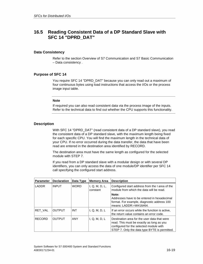
SFCs for Distributed I/Os
System Software for S7-300/400 System and Standard FunctionsA5E00171234-01 16-19
16.5 Reading Consistent Data of a DP Standard Slave withSFC 14 "DPRD_DAT"
Data Consistency
Refer to the section Overview of S7 Communication and S7 Basic Communication– Data consistency .
Purpose of SFC 14
You require SFC 14 "DPRD_DAT" because you can only read out a maximum offour continuous bytes using load instructions that access the I/Os or the processimage input table.
Note
If required you can also read consistent data via the process image of the inputs.Refer to the technical data to find out whether the CPU supports this functionality.
Description
With SFC 14 "DPRD_DAT" (read consistent data of a DP standard slave), you readthe consistent data of a DP standard slave, with the maximum length being fixedfor each specific CPU. You will find the maximum length in the technical data ofyour CPU. If no error occurred during the data transfer, the data that have beenread are entered in the destination area identified by RECORD.
The destination area must have the same length as configured for the selectedmodule with STEP 7.
If you read from a DP standard slave with a modular design or with several DPidentifiers, you can only access the data of one module/DP identifier per SFC 14call specifying the configured start address.
Parameter Declaration Data Type Memory Area Description
LADDR INPUT WORD I, Q, M, D, L,constant
Configured start address from the I area of themodule from which the data will be read.
Note:Addresses have to be entered in hexadecimalformat. For example, diagnostic address 100means: LADDR:=W#16#64.
RET_VAL OUTPUT INT I, Q, M, D, L If an error occurs while the function is active,the return value contains an error code.
RECORD OUTPUT ANY I, Q, M, D, L Destination area for the user data that wereread. This must be exactly as long as youconfigured for the selected module withSTEP 7. Only the data type BYTE is permitted.
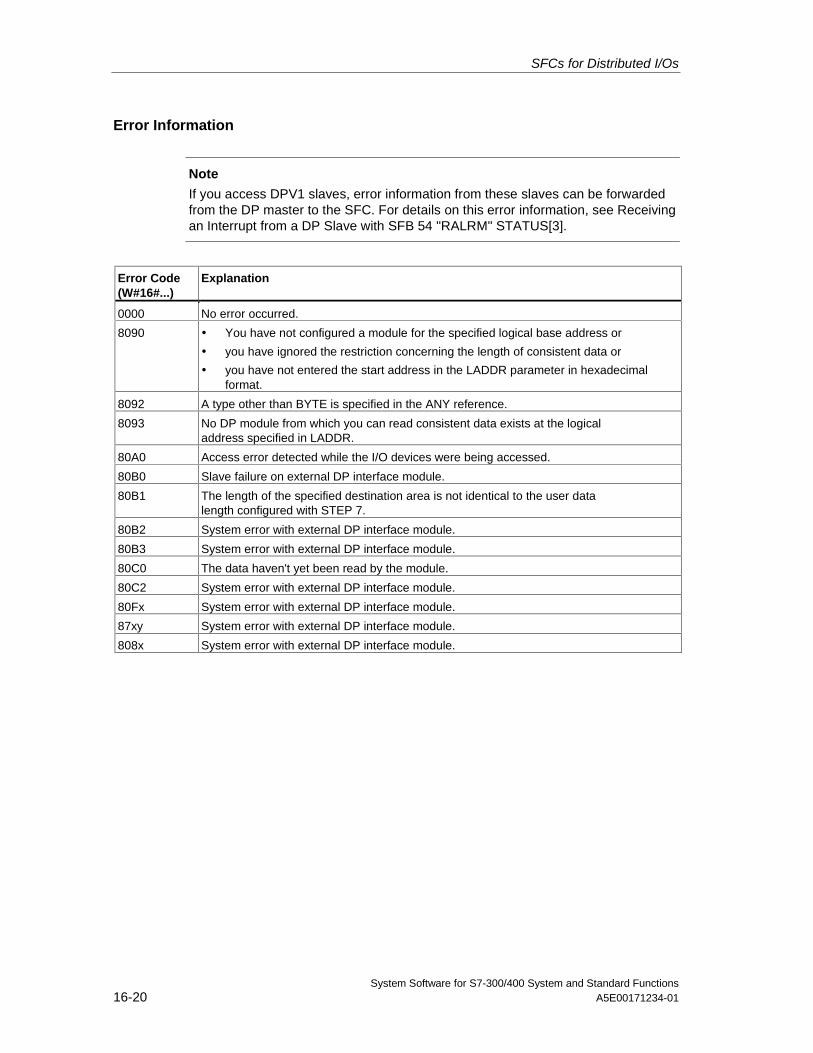
SFCs for Distributed I/Os
System Software for S7-300/400 System and Standard Functions16-20 A5E00171234-01
Error Information
Note
If you access DPV1 slaves, error information from these slaves can be forwardedfrom the DP master to the SFC. For details on this error information, see Receivingan Interrupt from a DP Slave with SFB 54 "RALRM" STATUS[3].
Error Code(W#16#...)
Explanation
0000 No error occurred.
8090 • You have not configured a module for the specified logical base address or
• you have ignored the restriction concerning the length of consistent data or
• you have not entered the start address in the LADDR parameter in hexadecimalformat.
8092 A type other than BYTE is specified in the ANY reference.
8093 No DP module from which you can read consistent data exists at the logicaladdress specified in LADDR.
80A0 Access error detected while the I/O devices were being accessed.
80B0 Slave failure on external DP interface module.
80B1 The length of the specified destination area is not identical to the user datalength configured with STEP 7.
80B2 System error with external DP interface module.
80B3 System error with external DP interface module.
80C0 The data haven't yet been read by the module.
80C2 System error with external DP interface module.
80Fx System error with external DP interface module.
87xy System error with external DP interface module.
808x System error with external DP interface module.
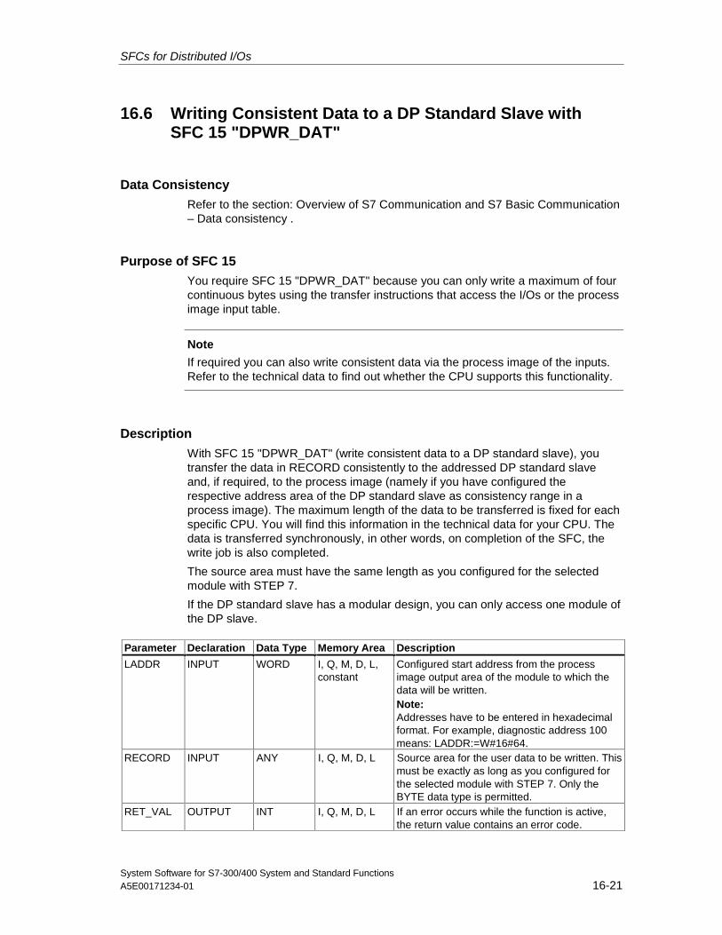
SFCs for Distributed I/Os
System Software for S7-300/400 System and Standard FunctionsA5E00171234-01 16-21
16.6 Writing Consistent Data to a DP Standard Slave withSFC 15 "DPWR_DAT"
Data ConsistencyRefer to the section: Overview of S7 Communication and S7 Basic Communication– Data consistency .
Purpose of SFC 15You require SFC 15 "DPWR_DAT" because you can only write a maximum of fourcontinuous bytes using the transfer instructions that access the I/Os or the processimage input table.
Note
If required you can also write consistent data via the process image of the inputs.Refer to the technical data to find out whether the CPU supports this functionality.
Description
With SFC 15 "DPWR_DAT" (write consistent data to a DP standard slave), youtransfer the data in RECORD consistently to the addressed DP standard slaveand, if required, to the process image (namely if you have configured therespective address area of the DP standard slave as consistency range in aprocess image). The maximum length of the data to be transferred is fixed for eachspecific CPU. You will find this information in the technical data for your CPU. Thedata is transferred synchronously, in other words, on completion of the SFC, thewrite job is also completed.
The source area must have the same length as you configured for the selectedmodule with STEP 7.
If the DP standard slave has a modular design, you can only access one module ofthe DP slave.
Parameter Declaration Data Type Memory Area Description
LADDR INPUT WORD I, Q, M, D, L,constant
Configured start address from the processimage output area of the module to which thedata will be written.Note:Addresses have to be entered in hexadecimalformat. For example, diagnostic address 100means: LADDR:=W#16#64.
RECORD INPUT ANY I, Q, M, D, L Source area for the user data to be written. Thismust be exactly as long as you configured forthe selected module with STEP 7. Only theBYTE data type is permitted.
RET_VAL OUTPUT INT I, Q, M, D, L If an error occurs while the function is active,the return value contains an error code.
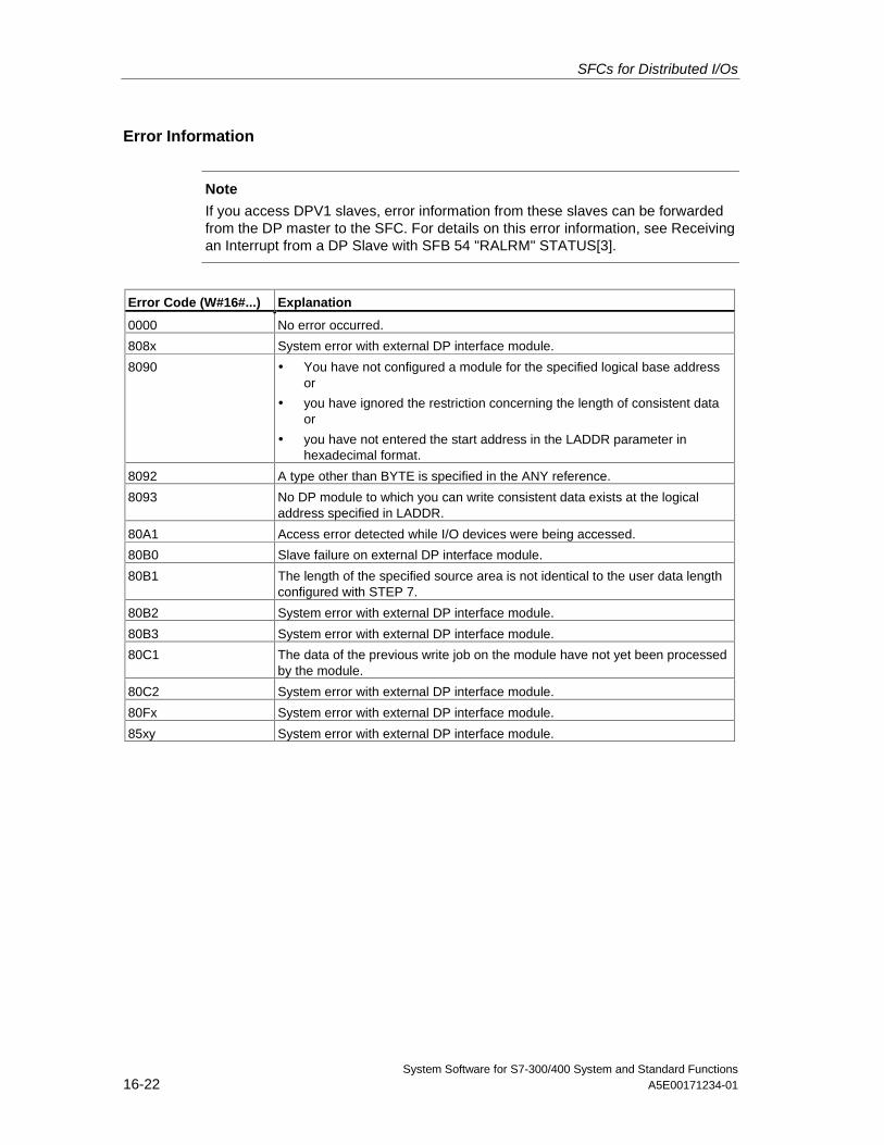
SFCs for Distributed I/Os
System Software for S7-300/400 System and Standard Functions16-22 A5E00171234-01
Error Information
Note
If you access DPV1 slaves, error information from these slaves can be forwardedfrom the DP master to the SFC. For details on this error information, see Receivingan Interrupt from a DP Slave with SFB 54 "RALRM" STATUS[3].
Error Code (W#16#...) Explanation
0000 No error occurred.
808x System error with external DP interface module.
8090 • You have not configured a module for the specified logical base addressor
• you have ignored the restriction concerning the length of consistent dataor
• you have not entered the start address in the LADDR parameter inhexadecimal format.
8092 A type other than BYTE is specified in the ANY reference.
8093 No DP module to which you can write consistent data exists at the logicaladdress specified in LADDR.
80A1 Access error detected while I/O devices were being accessed.
80B0 Slave failure on external DP interface module.
80B1 The length of the specified source area is not identical to the user data lengthconfigured with STEP 7.
80B2 System error with external DP interface module.
80B3 System error with external DP interface module.
80C1 The data of the previous write job on the module have not yet been processedby the module.
80C2 System error with external DP interface module.
80Fx System error with external DP interface module.
85xy System error with external DP interface module.
System Software for S7-300/400 System and Standard FunctionsA5E00171234-01 17-1
17 SFCs for Global Data Communication
17.1 Sending a GD Packet with SFC 60 "GD_SND"
Description
With SFC 60 "GD_SND" (global data send), the data of a GD packet are collectedand then sent on the path specified in the GD packet. The GD packet must alreadyhave been configured with STEP 7.
SFC 60 "GD_SND" can be called at any point in the user program.
The scan rate and the collection and sending of the data by the system at the cyclecheckpoint are not influenced by SFC 60 calls.
Interrupt ability
SFC 60 "GD_SND" can be interrupted by higher priority classes. It is also possiblethat SFC 60 is called again for the same GD packet in the higher priority class.
The data are then collected and sent in the higher priority class. When the programreturns to the interrupted SFC, this is terminated immediately and the data thathave already been collected are discarded.
This procedure means that during the processing of the highest priority class,consistent data are transferred (consistency in the sense defined for global data).
Data Consistency with GD
The following rules apply to the consistency of the data collected from the variousmemory areas and sent.
The following are consistent:
• The simple data types (bit, byte, word, and double word)
• An array of the data types byte, word, and double word up to a maximumlength depending on the specific CPU.
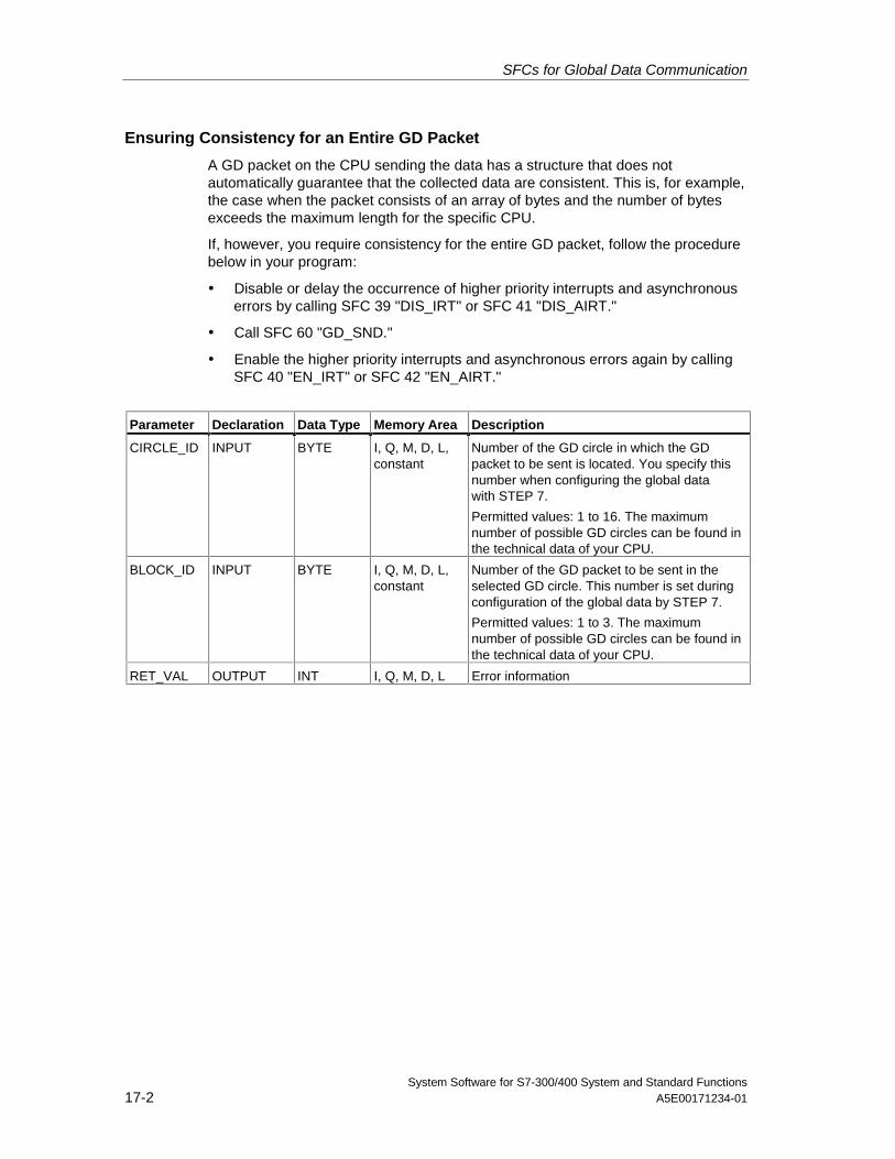
SFCs for Global Data Communication
System Software for S7-300/400 System and Standard Functions17-2 A5E00171234-01
Ensuring Consistency for an Entire GD Packet
A GD packet on the CPU sending the data has a structure that does notautomatically guarantee that the collected data are consistent. This is, for example,the case when the packet consists of an array of bytes and the number of bytesexceeds the maximum length for the specific CPU.
If, however, you require consistency for the entire GD packet, follow the procedurebelow in your program:
• Disable or delay the occurrence of higher priority interrupts and asynchronouserrors by calling SFC 39 "DIS_IRT" or SFC 41 "DIS_AIRT."
• Call SFC 60 "GD_SND."
• Enable the higher priority interrupts and asynchronous errors again by callingSFC 40 "EN_IRT" or SFC 42 "EN_AIRT."
Parameter Declaration Data Type Memory Area Description
CIRCLE_ID INPUT BYTE I, Q, M, D, L,constant
Number of the GD circle in which the GDpacket to be sent is located. You specify thisnumber when configuring the global datawith STEP 7.
Permitted values: 1 to 16. The maximumnumber of possible GD circles can be found inthe technical data of your CPU.
BLOCK_ID INPUT BYTE I, Q, M, D, L,constant
Number of the GD packet to be sent in theselected GD circle. This number is set duringconfiguration of the global data by STEP 7.
Permitted values: 1 to 3. The maximumnumber of possible GD circles can be found inthe technical data of your CPU.
RET_VAL OUTPUT INT I, Q, M, D, L Error information
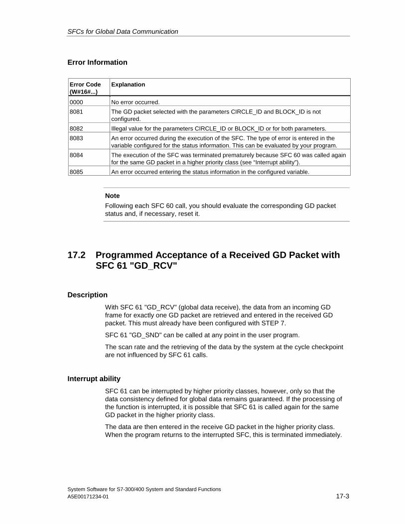
SFCs for Global Data Communication
System Software for S7-300/400 System and Standard FunctionsA5E00171234-01 17-3
Error Information
Error Code(W#16#...)
Explanation
0000 No error occurred.
8081 The GD packet selected with the parameters CIRCLE_ID and BLOCK_ID is notconfigured.
8082 Illegal value for the parameters CIRCLE_ID or BLOCK_ID or for both parameters.
8083 An error occurred during the execution of the SFC. The type of error is entered in thevariable configured for the status information. This can be evaluated by your program.
8084 The execution of the SFC was terminated prematurely because SFC 60 was called againfor the same GD packet in a higher priority class (see “Interrupt ability”).
8085 An error occurred entering the status information in the configured variable.
Note
Following each SFC 60 call, you should evaluate the corresponding GD packetstatus and, if necessary, reset it.
17.2 Programmed Acceptance of a Received GD Packet withSFC 61 "GD_RCV"
Description
With SFC 61 "GD_RCV" (global data receive), the data from an incoming GDframe for exactly one GD packet are retrieved and entered in the received GDpacket. This must already have been configured with STEP 7.
SFC 61 "GD_SND" can be called at any point in the user program.
The scan rate and the retrieving of the data by the system at the cycle checkpointare not influenced by SFC 61 calls.
Interrupt ability
SFC 61 can be interrupted by higher priority classes, however, only so that thedata consistency defined for global data remains guaranteed. If the processing ofthe function is interrupted, it is possible that SFC 61 is called again for the sameGD packet in the higher priority class.
The data are then entered in the receive GD packet in the higher priority class.When the program returns to the interrupted SFC, this is terminated immediately.
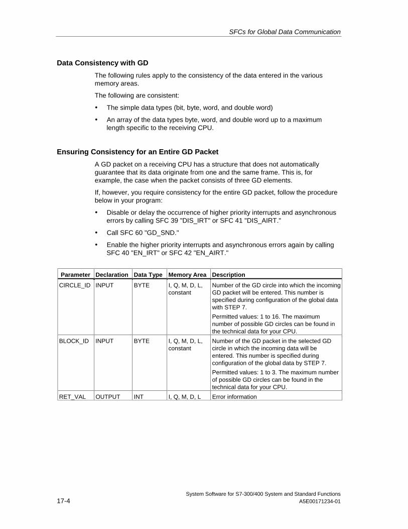
SFCs for Global Data Communication
System Software for S7-300/400 System and Standard Functions17-4 A5E00171234-01
Data Consistency with GD
The following rules apply to the consistency of the data entered in the variousmemory areas.
The following are consistent:
• The simple data types (bit, byte, word, and double word)
• An array of the data types byte, word, and double word up to a maximumlength specific to the receiving CPU.
Ensuring Consistency for an Entire GD Packet
A GD packet on a receiving CPU has a structure that does not automaticallyguarantee that its data originate from one and the same frame. This is, forexample, the case when the packet consists of three GD elements.
If, however, you require consistency for the entire GD packet, follow the procedurebelow in your program:
• Disable or delay the occurrence of higher priority interrupts and asynchronouserrors by calling SFC 39 "DIS_IRT" or SFC 41 "DIS_AIRT."
• Call SFC 60 "GD_SND."
• Enable the higher priority interrupts and asynchronous errors again by callingSFC 40 "EN_IRT" or SFC 42 "EN_AIRT."
Parameter Declaration Data Type Memory Area Description
CIRCLE_ID INPUT BYTE I, Q, M, D, L,constant
Number of the GD circle into which the incomingGD packet will be entered. This number isspecified during configuration of the global datawith STEP 7.
Permitted values: 1 to 16. The maximumnumber of possible GD circles can be found inthe technical data for your CPU.
BLOCK_ID INPUT BYTE I, Q, M, D, L,constant
Number of the GD packet in the selected GDcircle in which the incoming data will beentered. This number is specified duringconfiguration of the global data by STEP 7.
Permitted values: 1 to 3. The maximum numberof possible GD circles can be found in thetechnical data for your CPU.
RET_VAL OUTPUT INT I, Q, M, D, L Error information
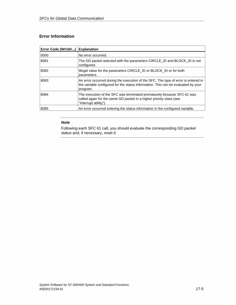
SFCs for Global Data Communication
System Software for S7-300/400 System and Standard FunctionsA5E00171234-01 17-5
Error Information
Error Code (W#16#...) Explanation
0000 No error occurred.
8081 The GD packet selected with the parameters CIRCLE_ID and BLOCK_ID is notconfigured.
8082 Illegal value for the parameters CIRCLE_ID or BLOCK_ID or for bothparameters.
8083 An error occurred during the execution of the SFC. The type of error is entered inthe variable configured for the status information. This can be evaluated by yourprogram.
8084 The execution of the SFC was terminated prematurely because SFC 61 wascalled again for the same GD packet in a higher priority class (see“Interrupt ability”).
8085 An error occurred entering the status information in the configured variable.
Note
Following each SFC 61 call, you should evaluate the corresponding GD packetstatus and, if necessary, reset it.

SFCs for Global Data Communication
System Software for S7-300/400 System and Standard Functions17-6 A5E00171234-01
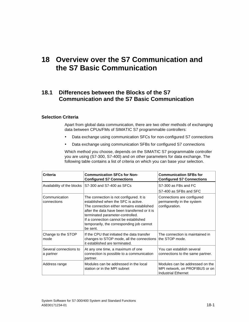
System Software for S7-300/400 System and Standard FunctionsA5E00171234-01 18-1
18 Overview over the S7 Communication andthe S7 Basic Communication
18.1 Differences between the Blocks of the S7Communication and the S7 Basic Communication
Selection Criteria
Apart from global data communication, there are two other methods of exchangingdata between CPUs/FMs of SIMATIC S7 programmable controllers:
• Data exchange using communication SFCs for non-configured S7 connections
• Data exchange using communication SFBs for configured S7 connections
Which method you choose, depends on the SIMATIC S7 programmable controlleryou are using (S7-300, S7-400) and on other parameters for data exchange. Thefollowing table contains a list of criteria on which you can base your selection.
Criteria Communication SFCs for Non-Configured S7 Connections
Communication SFBs forConfigured S7 Connections
Availability of the blocks S7-300 and S7-400 as SFCs S7-300 as FBs and FC
S7-400 as SFBs and SFC
Communicationconnections
The connection is not configured. It isestablished when the SFC is active.The connection either remains establishedafter the data have been transferred or it isterminated parameter-controlled.If a connection cannot be establishedtemporarily, the corresponding job cannotbe sent.
Connections are configuredpermanently in the systemconfiguration.
Change to the STOPmode
If the CPU that initiated the data transferchanges to STOP mode, all the connectionsit established are terminated.
The connection is maintained inthe STOP mode.
Several connections toa partner
At any one time, a maximum of oneconnection is possible to a communicationpartner.
You can establish severalconnections to the same partner.
Address range Modules can be addressed in the localstation or in the MPI subnet
Modules can be addressed on theMPI network, on PROFIBUS or onIndustrial Ethernet
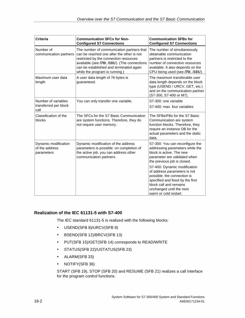
Overview over the S7 Communication and the S7 Basic Communication
System Software for S7-300/400 System and Standard Functions18-2 A5E00171234-01
Criteria Communication SFCs for Non-Configured S7 Connections
Communication SFBs forConfigured S7 Connections
Number ofcommunication partners
The number of communication partners thatcan be reached one after the other is notrestricted by the connection resourcesavailable (see /70/, /101/). (The connectionscan be established and terminated againwhile the program is running.)
The number of simultaneouslyobtainable communicationpartners is restricted to thenumber of connection resourcesavailable. It also depends on theCPU being used (see /70/, /101/).
Maximum user datalength
A user data length of 76 bytes isguaranteed.
The maximum transferable userdata length depends on the blocktype (USEND / URCV, GET, etc.)and on the communication partner(S7-300, S7-400 or M7).
Number of variablestransferred per blockcall
You can only transfer one variable. S7-300: one variable
S7-400: max. four variables
Classification of theblocks
The SFCs for the S7 Basic Communicationare system functions. Therefore, they donot require user memory.
The SFBs/FBs for the S7 BasicCommunication are systemfunction blocks. Therefore, theyrequire an instance DB for theactual parameters and the staticdata.
Dynamic modificationof the addressparameters
Dynamic modification of the addressparameters is possible: on completion ofthe active job, you can address othercommunication partners.
S7-300: You can reconfigure theaddressing parameters while theblock is active. The newparameter are validated whenthe previous job is closed.
S7-400: Dynamic modificationof address parameters is notpossible: the connection isspecified and fixed by the firstblock call and remainsunchanged until the nextwarm or cold restart.
Realization of the IEC 61131-5 with S7-400
The IEC standard 61131-5 is realized with the following blocks:
• USEND(SFB 8)/URCV(SFB 9)
• BSEND(SFB 12)/BRCV(SFB 13)
• PUT(SFB 15)/GET(SFB 14) corresponds to READ/WRITE
• STATUS(SFB 22)/USTATUS(SFB 23)
• ALARM(SFB 33)
• NOTIFY(SFB 36)
START (SFB 19), STOP (SFB 20) and RESUME (SFB 21) realizes a call interfacefor the program control functions.
Overview over the S7 Communication and the S7 Basic Communication
System Software for S7-300/400 System and Standard FunctionsA5E00171234-01 18-3
Realization of the IEC 61131-5 with S7-300
The IEC standard 61131-5 is realized with the following blocks:
• USEND(SFB 8)/URCV(SFB 9)
• BSEND(SFB 12)/BRCV(SFB 13)
• PUT(SFB 15)/GET(SFB 14) corresponds to READ/WRITE
18.2 Data Consistency
Definition
The size of the data area which can be modified simultaneously by concurrentprocesses is called the consistent data area. Data areas which are larger than theconsistent data area can thus be falsified as a whole.
This means that a data area which belongs together and which is larger thanconsistent data area can consist in part of new and of old consistent data blocks atthe same time.
Example
AN inconsistency can arise if a communication block is interrupted, for example, bya hardware interrupt OB with a higher priority. If the user program in this OB nowchanges the data which have already been processed in part by thecommunication block, the transferred data originate:
• IN part from the time before the hardware interrupt was processed
• And in part from the time after the hardware interrupt was processed
• This means that these data are inconsistent (not coherent).
Effect
If larger packages of data are to be transferred in a consistent form, the transfermay not be interrupted. This can, for example, increase the interrupt reaction timein the CPU.
This means: The higher the quantity of data which have to be transferredabsolutely consistently, the longer the interrupt reaction time of a system.
Overview over the S7 Communication and the S7 Basic Communication
System Software for S7-300/400 System and Standard Functions18-4 A5E00171234-01
Data Consistency at SIMATIC
If the user program includes a communication function, for example BSEND/BRCV,which accesses common data, access to this data area can, for example, becoordinated by using the parameter "DONE“. The data consistency of thecommunication areas which are transferred locally with a communication block cantherefore be ensured in the user program.
However, in the case of S7 communication functions, for example PUT/GET orwrite/read via OP communication the size of the consistent data area must alreadybe taken into consideration during the programming or configuration stage, sinceno communication block is available in the user program of the target device(server) to send synchronized communication data to the user program.
At the S7-300 and C7-300 (exception: CPU 318-2 DP) the communication data arecopied consistently into the user memory in blocks of 32 bytes in the cyclecheckpoint of the operating system. Data consistency is not guaranteed for largerdata areas. If a defined data consistency is required, the communication data in theuser program may not exceed 32 bytes (maximum of 8 bytes, depending on theversion).
In the S7-400 by contrast the communication data are not processed in the cyclecheckpoint, but in fixed time slices during the program cycle. The consistency of avariable is ensured by the system.
These communication areas can then be accessed consistently using thePUT/GET functions or reading/writing of variables, for example by an OP on anOS.
Recommendation
For further information on data consistency, please refer to the informationdescribing individual blocks as well as the manual Communication with SIMATIC.
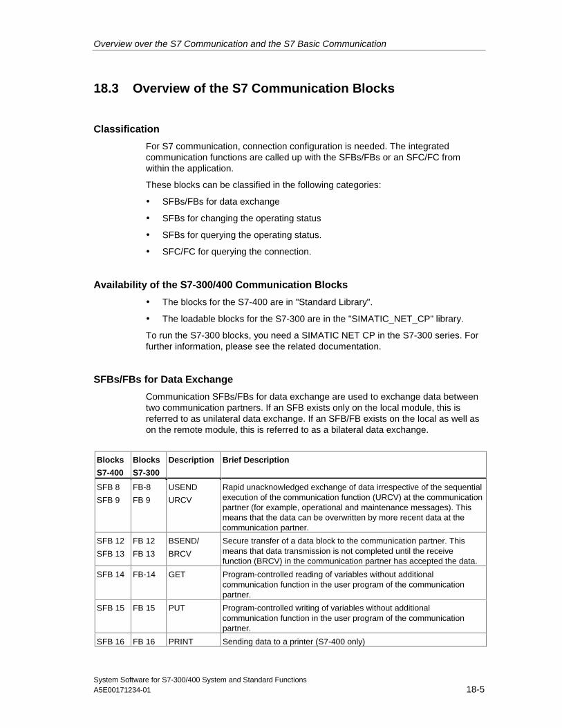
Overview over the S7 Communication and the S7 Basic Communication
System Software for S7-300/400 System and Standard FunctionsA5E00171234-01 18-5
18.3 Overview of the S7 Communication Blocks
Classification
For S7 communication, connection configuration is needed. The integratedcommunication functions are called up with the SFBs/FBs or an SFC/FC fromwithin the application.
These blocks can be classified in the following categories:
• SFBs/FBs for data exchange
• SFBs for changing the operating status
• SFBs for querying the operating status.
• SFC/FC for querying the connection.
Availability of the S7-300/400 Communication Blocks
• The blocks for the S7-400 are in "Standard Library".
• The loadable blocks for the S7-300 are in the "SIMATIC_NET_CP" library.
To run the S7-300 blocks, you need a SIMATIC NET CP in the S7-300 series. Forfurther information, please see the related documentation.
SFBs/FBs for Data Exchange
Communication SFBs/FBs for data exchange are used to exchange data betweentwo communication partners. If an SFB exists only on the local module, this isreferred to as unilateral data exchange. If an SFB/FB exists on the local as well ason the remote module, this is referred to as a bilateral data exchange.
Blocks
S7-400
Blocks
S7-300
Description Brief Description
SFB 8
SFB 9
FB-8
FB 9
USEND
URCV
Rapid unacknowledged exchange of data irrespective of the sequentialexecution of the communication function (URCV) at the communicationpartner (for example, operational and maintenance messages). Thismeans that the data can be overwritten by more recent data at thecommunication partner.
SFB 12
SFB 13
FB 12
FB 13
BSEND/
BRCV
Secure transfer of a data block to the communication partner. Thismeans that data transmission is not completed until the receivefunction (BRCV) in the communication partner has accepted the data.
SFB 14 FB-14 GET Program-controlled reading of variables without additionalcommunication function in the user program of the communicationpartner.
SFB 15 FB 15 PUT Program-controlled writing of variables without additionalcommunication function in the user program of the communicationpartner.
SFB 16 FB 16 PRINT Sending data to a printer (S7-400 only)
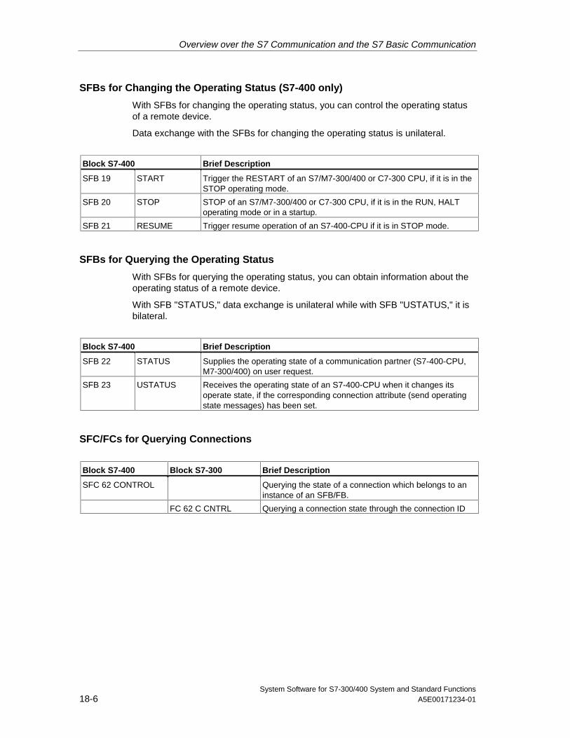
Overview over the S7 Communication and the S7 Basic Communication
System Software for S7-300/400 System and Standard Functions18-6 A5E00171234-01
SFBs for Changing the Operating Status (S7-400 only)
With SFBs for changing the operating status, you can control the operating statusof a remote device.
Data exchange with the SFBs for changing the operating status is unilateral.
Block S7-400 Brief Description
SFB 19 START Trigger the RESTART of an S7/M7-300/400 or C7-300 CPU, if it is in theSTOP operating mode.
SFB 20 STOP STOP of an S7/M7-300/400 or C7-300 CPU, if it is in the RUN, HALToperating mode or in a startup.
SFB 21 RESUME Trigger resume operation of an S7-400-CPU if it is in STOP mode.
SFBs for Querying the Operating Status
With SFBs for querying the operating status, you can obtain information about theoperating status of a remote device.
With SFB "STATUS," data exchange is unilateral while with SFB "USTATUS," it isbilateral.
Block S7-400 Brief Description
SFB 22 STATUS Supplies the operating state of a communication partner (S7-400-CPU,M7-300/400) on user request.
SFB 23 USTATUS Receives the operating state of an S7-400-CPU when it changes itsoperate state, if the corresponding connection attribute (send operatingstate messages) has been set.
SFC/FCs for Querying Connections
Block S7-400 Block S7-300 Brief Description
SFC 62 CONTROL Querying the state of a connection which belongs to aninstance of an SFB/FB.
FC 62 C CNTRL Querying a connection state through the connection ID
Overview over the S7 Communication and the S7 Basic Communication
System Software for S7-300/400 System and Standard FunctionsA5E00171234-01 18-7
Tip:
You can also use SFC 87 C_DIAG to perform a diagnosis of the actual connectionstate (only for S7-400).
Sample Program
A sample program for S7-400 which shows the use of the SFBs for the S7communication is supplied with STEP 7. This sample program is calledstep7\examples\com_sfb. It is included under the sample programs in the pathfolder "..\STEP7\Examples\ZDT01_10".
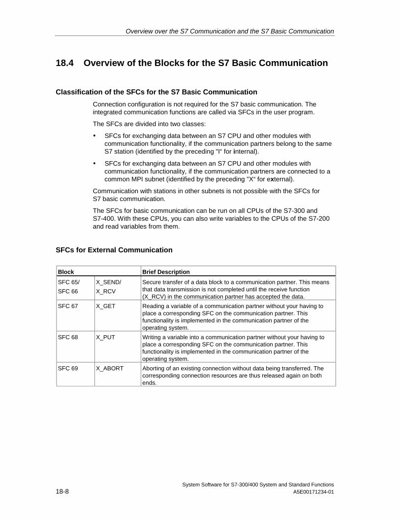
Overview over the S7 Communication and the S7 Basic Communication
System Software for S7-300/400 System and Standard Functions18-8 A5E00171234-01
18.4 Overview of the Blocks for the S7 Basic Communication
Classification of the SFCs for the S7 Basic Communication
Connection configuration is not required for the S7 basic communication. Theintegrated communication functions are called via SFCs in the user program.
The SFCs are divided into two classes:
• SFCs for exchanging data between an S7 CPU and other modules withcommunication functionality, if the communication partners belong to the sameS7 station (identified by the preceding "I“ for internal).
• SFCs for exchanging data between an S7 CPU and other modules withcommunication functionality, if the communication partners are connected to acommon MPI subnet (identified by the preceding "X“ for external).
Communication with stations in other subnets is not possible with the SFCs forS7 basic communication.
The SFCs for basic communication can be run on all CPUs of the S7-300 andS7-400. With these CPUs, you can also write variables to the CPUs of the S7-200and read variables from them.
SFCs for External Communication
Block Brief Description
SFC 65/
SFC 66
X_SEND/
X_RCV
Secure transfer of a data block to a communication partner. This meansthat data transmission is not completed until the receive function(X_RCV) in the communication partner has accepted the data.
SFC 67 X_GET Reading a variable of a communication partner without your having toplace a corresponding SFC on the communication partner. Thisfunctionality is implemented in the communication partner of theoperating system.
SFC 68 X_PUT Writing a variable into a communication partner without your having toplace a corresponding SFC on the communication partner. Thisfunctionality is implemented in the communication partner of theoperating system.
SFC 69 X_ABORT Aborting of an existing connection without data being transferred. Thecorresponding connection resources are thus released again on bothends.
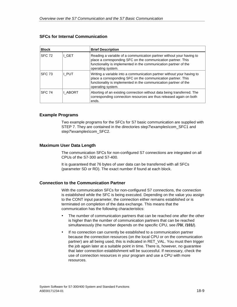
Overview over the S7 Communication and the S7 Basic Communication
System Software for S7-300/400 System and Standard FunctionsA5E00171234-01 18-9
SFCs for Internal Communication
Block Brief Description
SFC 72 I_GET Reading a variable of a communication partner without your having toplace a corresponding SFC on the communication partner. Thisfunctionality is implemented in the communication partner of theoperating system.
SFC 73 I_PUT Writing a variable into a communication partner without your having toplace a corresponding SFC on the communication partner. Thisfunctionality is implemented in the communication partner of theoperating system.
SFC 74 I_ABORT Aborting of an existing connection without data being transferred. Thecorresponding connection resources are thus released again on bothends.
Example Programs
Two example programs for the SFCs for S7 basic communication are supplied withSTEP 7. They are contained in the directories step7\examples\com_SFC1 andstep7\examples\com_SFC2.
Maximum User Data Length
The communication SFCs for non-configured S7 connections are integrated on allCPUs of the S7-300 and S7-400.
It is guaranteed that 76 bytes of user data can be transferred with all SFCs(parameter SD or RD). The exact number if found at each block.
Connection to the Communication Partner
With the communication SFCs for non-configured S7 connections, the connectionis established while the SFC is being executed. Depending on the value you assignto the CONT input parameter, the connection either remains established or isterminated on completion of the data exchange. This means that thecommunication has the following characteristics:
• The number of communication partners that can be reached one after the otheris higher than the number of communication partners that can be reachedsimultaneously (the number depends on the specific CPU, see /70/, /101/).
• If no connection can currently be established to a communication partnerbecause the connection resources (on the local CPU or on the communicationpartner) are all being used, this is indicated in RET_VAL. You must then triggerthe job again later at a suitable point in time. There is, however, no guaranteethat later connection establishment will be successful. If necessary, check theuse of connection resources in your program and use a CPU with moreresources.
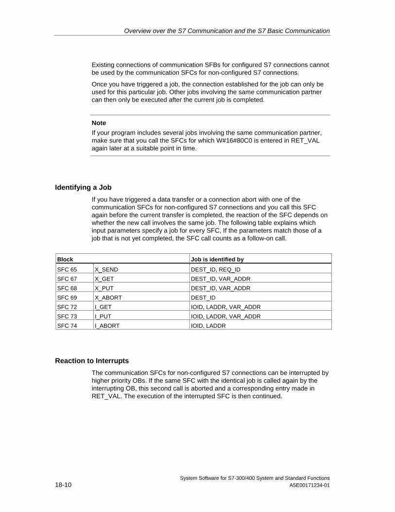
Overview over the S7 Communication and the S7 Basic Communication
System Software for S7-300/400 System and Standard Functions18-10 A5E00171234-01
Existing connections of communication SFBs for configured S7 connections cannotbe used by the communication SFCs for non-configured S7 connections.
Once you have triggered a job, the connection established for the job can only beused for this particular job. Other jobs involving the same communication partnercan then only be executed after the current job is completed.
Note
If your program includes several jobs involving the same communication partner,make sure that you call the SFCs for which W#16#80C0 is entered in RET_VALagain later at a suitable point in time.
Identifying a Job
If you have triggered a data transfer or a connection abort with one of thecommunication SFCs for non-configured S7 connections and you call this SFCagain before the current transfer is completed, the reaction of the SFC depends onwhether the new call involves the same job. The following table explains whichinput parameters specify a job for every SFC, If the parameters match those of ajob that is not yet completed, the SFC call counts as a follow-on call.
Block Job is identified by
SFC 65 X_SEND DEST_ID, REQ_ID
SFC 67 X_GET DEST_ID, VAR_ADDR
SFC 68 X_PUT DEST_ID, VAR_ADDR
SFC 69 X_ABORT DEST_ID
SFC 72 I_GET IOID, LADDR, VAR_ADDR
SFC 73 I_PUT IOID, LADDR, VAR_ADDR
SFC 74 I_ABORT IOID, LADDR
Reaction to Interrupts
The communication SFCs for non-configured S7 connections can be interrupted byhigher priority OBs. If the same SFC with the identical job is called again by theinterrupting OB, this second call is aborted and a corresponding entry made inRET_VAL. The execution of the interrupted SFC is then continued.
Overview over the S7 Communication and the S7 Basic Communication
System Software for S7-300/400 System and Standard FunctionsA5E00171234-01 18-11
Access to the Work Memory of the CPU
Regardless of the number of user data to be transferred, the communicationfunctions of the operating system access the work memory of the CPU in fields ofthe maximum length, so that the interrupt reaction time is not extended by the useof communication functions.
Depending on how you set the maximum cycle load resulting from communicationwith STEP 7, the work memory can be accessed several times during theexecution of a job by the communication functions of the operating system.
Client Changes to STOP
If the CPU that initiated a job (and therefore established the connection) changesto STOP during a data transfer, all the connections it established are terminated.
Making Program Changes
All parts of your program that immediately affect the calls for communication SFCsfor non-configured S7 connections must only be modified in the STOP mode. Thisincludes, in particular, deleting FCs, FBs, or OBs containing calls forcommunication SFCs for non-configured S7 connections.
After modifying the program, you must perform a warm or cold restart.
Not following these rules can lead to resources remaining assigned and theprogrammable controller being subsequently in an undefined state.

Overview over the S7 Communication and the S7 Basic Communication
System Software for S7-300/400 System and Standard Functions18-12 A5E00171234-01
System Software for S7-300/400 System and Standard FunctionsA5E00171234-01 19-1
19 S7 Communication
19.1 Common Parameters of the SFBs/FBs and SFCs/FCs forS7 Communication
Classification
The parameters of communication SFBs/FBs for configured S7 connections can bedivided into the following five categories according to their functions:
1. Control parameters are used to activate a block.
2. Addressing parameters are used to address the remote communication partner.
3. Send parameters point to the data areas that are to be sent to the remotepartner.
4. Receive parameters point to the data areas where the data received fromremote partners will be entered.
5. Status parameters are used to monitor whether the block has completed itstask without error or for the analysis of any errors that have occurred.
Control Parameters
Data exchange will only be activated if the appropriate control parameters have adefined signal state (for example are set) when the SFB/FB is called or when thesignal state has undergone a specific change since the previous SFB/FB call (forexample, positive edge).
Note on S7-300
For the first call, set the parameter REQ to FALSE.
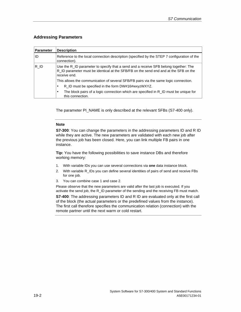
S7 Communication
System Software for S7-300/400 System and Standard Functions19-2 A5E00171234-01
Addressing Parameters
Parameter Description
ID Reference to the local connection description (specified by the STEP 7 configuration of theconnection).
R_ID Use the R_ID parameter to specify that a send and a receive SFB belong together: TheR_ID parameter must be identical at the SFB/FB on the send end and at the SFB on thereceive end.
This allows the communication of several SFB/FB pairs via the same logic connection.
• R_ID must be specified in the form DW#16#wxyzWXYZ.
• The block pairs of a logic connection which are specified in R_ID must be unique forthis connection.
The parameter PI_NAME is only described at the relevant SFBs (S7-400 only).
Note
S7-300: You can change the parameters in the addressing parameters ID and R IDwhile they are active. The new parameters are validated with each new job afterthe previous job has been closed. Here, you can link multiple FB pairs in oneinstance.
Tip: You have the following possibilities to save instance DBs and thereforeworking memory:
1. With variable IDs you can use several connections via one data instance block.
2. With variable R_IDs you can define several identities of pairs of send and receive FBsfor one job.
3. You can combine case 1 and case 2.
Please observe that the new parameters are valid after the last job is executed. If youactivate the send job, the R_ID parameter of the sending and the receiving FB must match.
S7-400: The addressing parameters ID and R ID are evaluated only at the first callof the block (the actual parameters or the predefined values from the instance).The first call therefore specifies the communication relation (connection) with theremote partner until the next warm or cold restart.
S7 Communication
System Software for S7-300/400 System and Standard FunctionsA5E00171234-01 19-3
Status Parameters
With the status parameters, you monitor whether the block has completed its taskcorrectly or whether it is still active. The status parameters also indicate errors.
Note
The status parameters are valid for one cycle only, namely from the first instructionwhich follows the SFB/FB call until the next SFB/FB call. As a result, you mustevaluate these parameters after each block cycle.
Send and Receive Parameters
If you do not use all send or receive parameters of an SFB/FB, the first unusedparameter must be a NIL pointer (see /232/) and the parameters used must belocated one after the other and without any gaps.
Note for S7-400
During the first call, the ANY pointer specifies the maximum amount of user datathat can be transferred for the job. That is to say, a communication buffer iscreated in the work memory of the CPU to ensure data consistency. This bufferoccupies up to 480 bytes of work memory. We recommend you run the first call inthe warm or cold restart OB if the block is not reloaded with the SFB call when theCPU is in RUN mode.
At subsequent calls you can send/receive any amount of data, however, no morethan with the first call.
The SFBs BSEND and BRCV are an exception to this rule. With them you cantransmit up to 64 Kbytes per job (see Sending Block-Related Data with SFB/FB 12"BSEND" und Receiving Block-Related Data with SFB/FB 13 "BRCV"
With SFBs/FBs for bilateral communication:
• The number of the SD_i and RD_i parameters used must match on the sendand receive side.
• The data types of the SD_i and DR_i parameters that belong together mustmatch on the send and receive side.
• The amount of data to be sent according to the SD_i parameter must notexceed the area made available by the corresponding RD_i parameter (notvalid for BSEND/BRCV).
ERROR = 1 and STATUS = 4 indicate that you have violated the above rules.
This maximum user data length depends on whether the remote partner is anS7-300 or an S7-400.
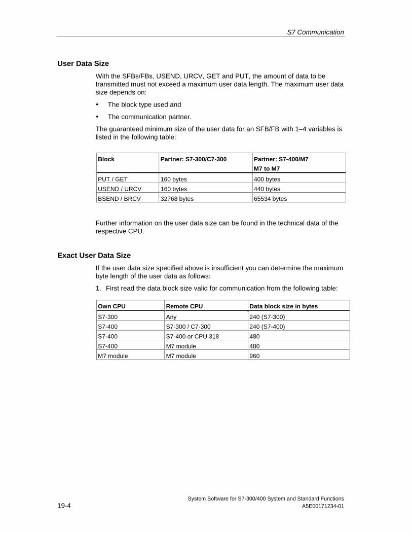
S7 Communication
System Software for S7-300/400 System and Standard Functions19-4 A5E00171234-01
User Data Size
With the SFBs/FBs, USEND, URCV, GET and PUT, the amount of data to betransmitted must not exceed a maximum user data length. The maximum user datasize depends on:
• The block type used and
• The communication partner.
The guaranteed minimum size of the user data for an SFB/FB with 1–4 variables islisted in the following table:
Block Partner: S7-300/C7-300 Partner: S7-400/M7
M7 to M7
PUT / GET 160 bytes 400 bytes
USEND / URCV 160 bytes 440 bytes
BSEND / BRCV 32768 bytes 65534 bytes
Further information on the user data size can be found in the technical data of therespective CPU.
Exact User Data Size
If the user data size specified above is insufficient you can determine the maximumbyte length of the user data as follows:
1. First read the data block size valid for communication from the following table:
Own CPU Remote CPU Data block size in bytes
S7-300 Any 240 (S7-300)
S7-400 S7-300 / C7-300 240 (S7-400)
S7-400 S7-400 or CPU 318 480
S7-400 M7 module 480
M7 module M7 module 960
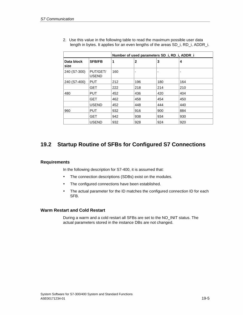
S7 Communication
System Software for S7-300/400 System and Standard FunctionsA5E00171234-01 19-5
2. Use this value in the following table to read the maximum possible user datalength in bytes. It applies for an even lengths of the areas SD_i, RD_i, ADDR_i.
Number of used parameters SD_i, RD_i, ADDR_i
Data blocksize
SFB/FB 1 2 3 4
240 (S7-300) PUT/GET/USEND
160 - - -
240 (S7-400) PUT 212 196 180 164
GET 222 218 214 210
480 PUT 452 436 420 404
GET 462 458 454 450
USEND 452 448 444 440
960 PUT 932 916 900 884
GET 942 938 934 930
USEND 932 928 924 920
19.2 Startup Routine of SFBs for Configured S7 Connections
Requirements
In the following description for S7-400, it is assumed that:
• The connection descriptions (SDBs) exist on the modules.
• The configured connections have been established.
• The actual parameter for the ID matches the configured connection ID for eachSFB.
Warm Restart and Cold Restart
During a warm and a cold restart all SFBs are set to the NO_INIT status. Theactual parameters stored in the instance DBs are not changed.
S7 Communication
System Software for S7-300/400 System and Standard Functions19-6 A5E00171234-01
Warm Restart and Cold Restart with SFBs for Bilateral Data Exchange
In general, the two modules with SFBs for bilateral data exchange do not both gothrough a warm or cold restart simultaneously. The reaction of the SFB is governedby the rules below:
The receive blocks (SFBs URCV, BRCV) react as follows:
• If the SFB has received a job but has not acknowledged this job at the time ofthe warm or cold restart, it generates a sequence abort frame (CFB, BRCV)and then immediately branches to the NO_INIT status.
• With SFB BRCV, it is possible that another data segment will be receiveddespite having sent the sequence abort. This will be discarded locally.
• SFB URCV changes to the NO_INIT status immediately.
The send blocks (SFBs USEND, BSEND) react as follows:
• If SFB BSEND has started a job sequence that has not yet been completed, itsends a sequence abort when the warm or cold restart is initiated. It thenbranches to the NO_INIT status immediately afterwards. An acknowledgementthat arrives at a later time is discarded locally.
• If SFB BSEND has already sent or received a sequence abort when the warmor cold restart is requested, it changes immediately to the NO_INIT status.
• In all other cases and whenever the SFB sends only messages (for example,SFB USEND), local processing is aborted and the SFB immediately branchesto the NO_INIT status.
Warm Restart and Cold Restart with SFBs for Unilateral Data Exchange
It is assumed that the server on the communication partner is operational after theconnections have been established, in other words that it can process jobs oroutput messages at any time.
SFBs that send out jobs and expect acknowledgements react to a complete restartas follows:
The current processing is aborted and the CFB branches to the NO_INIT statusimmediately afterwards. If an acknowledgement for the job sent prior to the warmor cold restart arrives later, it is discarded locally.
A new job may have been sent before the acknowledgement of the earlier job isreceived.
SFBs that output or receive messages react as follows:
• The current processing is aborted and the CFB branches to the NO_INITstatus immediately afterwards.
• With SFB USTATUS, messages that arrive during the NO_INIT andDISABLED statuses are discarded locally.
S7 Communication
System Software for S7-300/400 System and Standard FunctionsA5E00171234-01 19-7
Reaction to a Hot Restart
The SFBs for S7 communication are set to the NO_INIT status only during a warmor cold restart. This means that they react like user function blocks that can beresumed following a hot restart.
Reaction to a Memory Reset
A memory reset always causes all connections to be terminated. Since a warm orcold restart is the only possible startup type for the user program after a memoryreset, all SFBs for S7 communications (if they still exist) are set to the NO_INITstatus and initialized. Partner blocks in a module whose memory was not resetchange to the IDLE, ENABLED or DISABLED statuses as a reaction to theconnection being terminated.
19.3 How SFBs React to Problems
The following section describes how SFBs for S7 communication in S7-400 reactto problems.
Connection Terminated
The connections allocated to the SFB instances are monitored.
If a connection is terminated, the reaction of the SFB depends on its internalstatus.
If the break down of the connection is detected while the block is in the IDLE orENABLED status, the SFB reacts as follows:
• It branches to the ERROR status and outputs the error ID "Communicationproblems" at the ERROR and STATUS output parameters.
• When it is next called, the block returns to its original status and checks theconnection again.
A communication SFB that is not in the IDLE or DISABLED statuses reacts asfollows:
• It aborts processing, changes to the ERROR status immediately or at the nextblock call and outputs the error ID "Communication problems" at the ERRORand STATUS output parameters.
• When it is next called, the block changes to the IDLE, DISABLED or ENABLEDstatus. In the IDLE and ENABLED status the connection is checked again.
This procedure will also be executed if the connection has again been set up in themeantime.
S7 Communication
System Software for S7-300/400 System and Standard Functions19-8 A5E00171234-01
Power Down
A power down with battery backup followed by a restart causes all establishedconnections to be terminated. The points made above therefore apply to all blocksinvolved.
If there is a power down with battery backup followed by an automatic warm or coldrestart, the points made about terminated connections and warm or cold restartsapply.
In the special case of an automatic warm or cold restart without battery backup,where a memory reset is executed automatically after power returns, the SFBs forS7 communications react as described in the section "Startup Routine of the SFBsFor S7 Communications."
Reaction to Operating Mode Changes
If the operating mode changes between the STOP, START, RUN, and HOLDstatuses, the communication SFB remains in its current status (exception: during awarm or cold restart, it changes to the NO_INIT status). This applies both to SFBsfor unilateral as well as SFBs for bilateral communication.
Error Interface to the User Program
If an error occurs during the processing of a communication SFB, it alwayschanges to the ERROR status. At the same time the ERROR output parameter isset to 1 and the corresponding error ID is entered in the STATUS outputparameter. You can evaluate this error information in your program.
Examples of possible errors:
• Error when collecting send data.
• Error when copying receive data into the receive areas (for example,attempting to access a DB that does not exist).
• The length of the data area sent does not match the length of the receive areaspecified in the partner SFB.
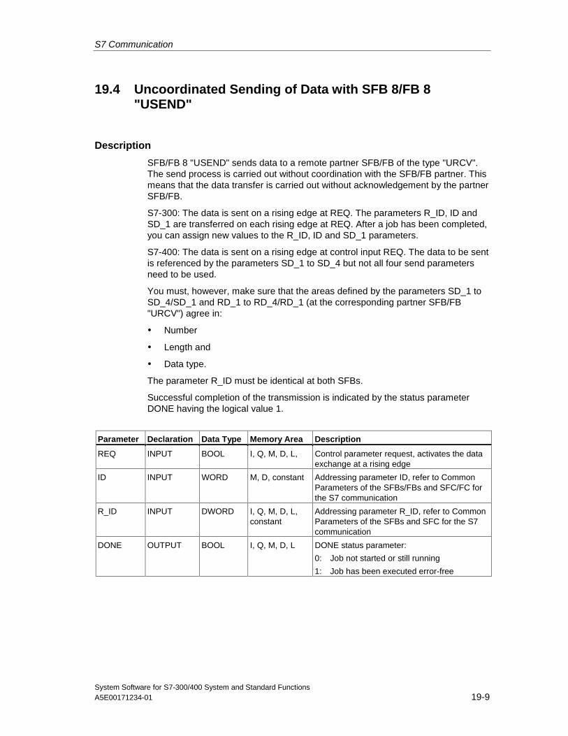
S7 Communication
System Software for S7-300/400 System and Standard FunctionsA5E00171234-01 19-9
19.4 Uncoordinated Sending of Data with SFB 8/FB 8"USEND"
Description
SFB/FB 8 "USEND" sends data to a remote partner SFB/FB of the type "URCV".The send process is carried out without coordination with the SFB/FB partner. Thismeans that the data transfer is carried out without acknowledgement by the partnerSFB/FB.
S7-300: The data is sent on a rising edge at REQ. The parameters R_ID, ID andSD_1 are transferred on each rising edge at REQ. After a job has been completed,you can assign new values to the R_ID, ID and SD_1 parameters.
S7-400: The data is sent on a rising edge at control input REQ. The data to be sentis referenced by the parameters SD_1 to SD_4 but not all four send parametersneed to be used.
You must, however, make sure that the areas defined by the parameters SD_1 toSD_4/SD_1 and RD_1 to RD_4/RD_1 (at the corresponding partner SFB/FB"URCV") agree in:
• Number
• Length and
• Data type.
The parameter R_ID must be identical at both SFBs.
Successful completion of the transmission is indicated by the status parameterDONE having the logical value 1.
Parameter Declaration Data Type Memory Area Description
REQ INPUT BOOL I, Q, M, D, L, Control parameter request, activates the dataexchange at a rising edge
ID INPUT WORD M, D, constant Addressing parameter ID, refer to CommonParameters of the SFBs/FBs and SFC/FC forthe S7 communication
R_ID INPUT DWORD I, Q, M, D, L,constant
Addressing parameter R_ID, refer to CommonParameters of the SFBs and SFC for the S7communication
DONE OUTPUT BOOL I, Q, M, D, L DONE status parameter:
0: Job not started or still running
1: Job has been executed error-free
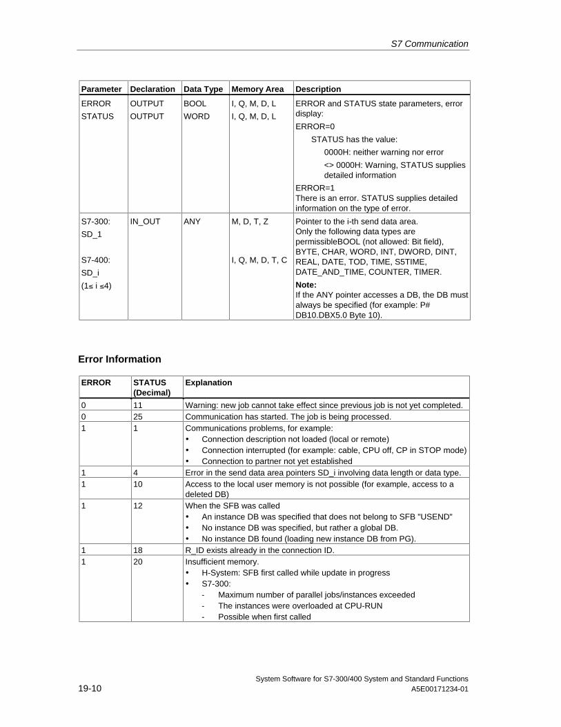
S7 Communication
System Software for S7-300/400 System and Standard Functions19-10 A5E00171234-01
Parameter Declaration Data Type Memory Area Description
ERROR
STATUS
OUTPUT
OUTPUT
BOOL
WORD
I, Q, M, D, L
I, Q, M, D, L
ERROR and STATUS state parameters, errordisplay:
ERROR=0
STATUS has the value:
0000H: neither warning nor error
<> 0000H: Warning, STATUS suppliesdetailed information
ERROR=1There is an error. STATUS supplies detailedinformation on the type of error.
S7-300:
SD_1
S7-400:
SD_i
(1≤ i ≤4)
IN_OUT ANY M, D, T, Z
I, Q, M, D, T, C
Pointer to the i-th send data area.Only the following data types arepermissibleBOOL (not allowed: Bit field),BYTE, CHAR, WORD, INT, DWORD, DINT,REAL, DATE, TOD, TIME, S5TIME,DATE_AND_TIME, COUNTER, TIMER.
Note:If the ANY pointer accesses a DB, the DB mustalways be specified (for example: P#DB10.DBX5.0 Byte 10).
Error Information
ERROR STATUS(Decimal)
Explanation
0 11 Warning: new job cannot take effect since previous job is not yet completed.0 25 Communication has started. The job is being processed.1 1 Communications problems, for example:
• Connection description not loaded (local or remote)• Connection interrupted (for example: cable, CPU off, CP in STOP mode)• Connection to partner not yet established
1 4 Error in the send data area pointers SD_i involving data length or data type.1 10 Access to the local user memory is not possible (for example, access to a
deleted DB)1 12 When the SFB was called
• An instance DB was specified that does not belong to SFB "USEND"• No instance DB was specified, but rather a global DB.• No instance DB found (loading new instance DB from PG).
1 18 R_ID exists already in the connection ID.1 20 Insufficient memory.
• H-System: SFB first called while update in progress• S7-300:
- Maximum number of parallel jobs/instances exceeded- The instances were overloaded at CPU-RUN- Possible when first called
S7 Communication
System Software for S7-300/400 System and Standard FunctionsA5E00171234-01 19-11
Data Consistency
S7-300: To ensure data consistency, you can only write to the send area SD_1again after the current send operation is complete. This is the case when the valueof the status parameter DONE changes to 1.
S7-400: When a send operation is activated (rising edge at REQ) the data to besent from the send area SD_i are copied from the user program. After the blockcall, you can write to these areas without corrupting the current send data.
Note
The send operation is only complete when the DONE status parameter has thevalue 1.
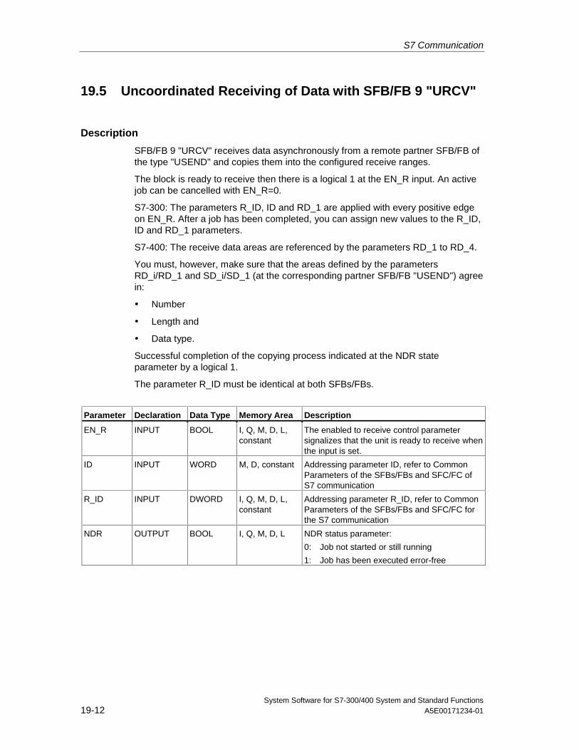
S7 Communication
System Software for S7-300/400 System and Standard Functions19-12 A5E00171234-01
19.5 Uncoordinated Receiving of Data with SFB/FB 9 "URCV"
Description
SFB/FB 9 "URCV" receives data asynchronously from a remote partner SFB/FB ofthe type "USEND" and copies them into the configured receive ranges.
The block is ready to receive then there is a logical 1 at the EN_R input. An activejob can be cancelled with EN_R=0.
S7-300: The parameters R_ID, ID and RD_1 are applied with every positive edgeon EN_R. After a job has been completed, you can assign new values to the R_ID,ID and RD_1 parameters.
S7-400: The receive data areas are referenced by the parameters RD_1 to RD_4.
You must, however, make sure that the areas defined by the parametersRD_i/RD_1 and SD_i/SD_1 (at the corresponding partner SFB/FB "USEND") agreein:
• Number
• Length and
• Data type.
Successful completion of the copying process indicated at the NDR stateparameter by a logical 1.
The parameter R_ID must be identical at both SFBs/FBs.
Parameter Declaration Data Type Memory Area Description
EN_R INPUT BOOL I, Q, M, D, L,constant
The enabled to receive control parametersignalizes that the unit is ready to receive whenthe input is set.
ID INPUT WORD M, D, constant Addressing parameter ID, refer to CommonParameters of the SFBs/FBs and SFC/FC ofS7 communication
R_ID INPUT DWORD I, Q, M, D, L,constant
Addressing parameter R_ID, refer to CommonParameters of the SFBs/FBs and SFC/FC forthe S7 communication
NDR OUTPUT BOOL I, Q, M, D, L NDR status parameter:
0: Job not started or still running
1: Job has been executed error-free
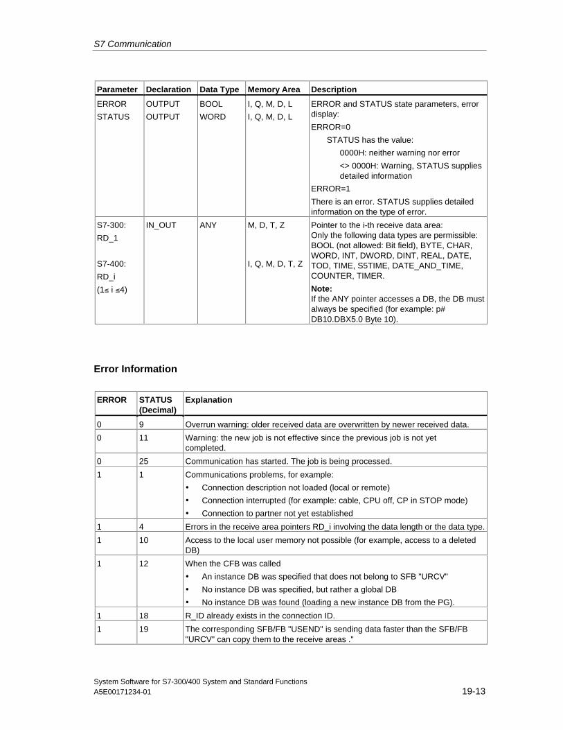
S7 Communication
System Software for S7-300/400 System and Standard FunctionsA5E00171234-01 19-13
Parameter Declaration Data Type Memory Area Description
ERROR
STATUS
OUTPUT
OUTPUT
BOOL
WORD
I, Q, M, D, L
I, Q, M, D, L
ERROR and STATUS state parameters, errordisplay:
ERROR=0
STATUS has the value:
0000H: neither warning nor error
<> 0000H: Warning, STATUS suppliesdetailed information
ERROR=1
There is an error. STATUS supplies detailedinformation on the type of error.
S7-300:
RD_1
S7-400:
RD_i
(1≤ i ≤4)
IN_OUT ANY M, D, T, Z
I, Q, M, D, T, Z
Pointer to the i-th receive data area:Only the following data types are permissible:BOOL (not allowed: Bit field), BYTE, CHAR,WORD, INT, DWORD, DINT, REAL, DATE,TOD, TIME, S5TIME, DATE_AND_TIME,COUNTER, TIMER.
Note:If the ANY pointer accesses a DB, the DB mustalways be specified (for example: p#DB10.DBX5.0 Byte 10).
Error Information
ERROR STATUS(Decimal)
Explanation
0 9 Overrun warning: older received data are overwritten by newer received data.
0 11 Warning: the new job is not effective since the previous job is not yetcompleted.
0 25 Communication has started. The job is being processed.
1 1 Communications problems, for example:
• Connection description not loaded (local or remote)
• Connection interrupted (for example: cable, CPU off, CP in STOP mode)
• Connection to partner not yet established
1 4 Errors in the receive area pointers RD_i involving the data length or the data type.
1 10 Access to the local user memory not possible (for example, access to a deletedDB)
1 12 When the CFB was called
• An instance DB was specified that does not belong to SFB "URCV"
• No instance DB was specified, but rather a global DB
• No instance DB was found (loading a new instance DB from the PG).
1 18 R_ID already exists in the connection ID.
1 19 The corresponding SFB/FB "USEND" is sending data faster than the SFB/FB"URCV" can copy them to the receive areas ."
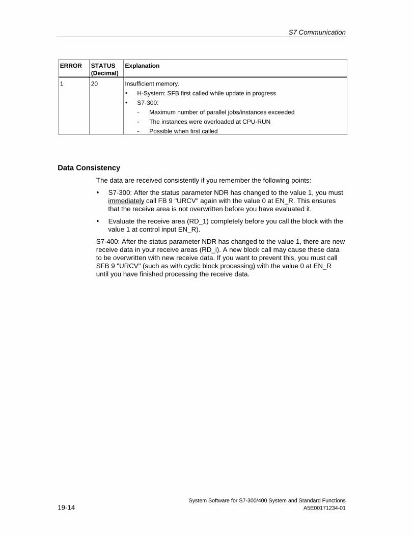
S7 Communication
System Software for S7-300/400 System and Standard Functions19-14 A5E00171234-01
ERROR STATUS(Decimal)
Explanation
1 20 Insufficient memory.
• H-System: SFB first called while update in progress
• S7-300:
- Maximum number of parallel jobs/instances exceeded
- The instances were overloaded at CPU-RUN
- Possible when first called
Data Consistency
The data are received consistently if you remember the following points:
• S7-300: After the status parameter NDR has changed to the value 1, you mustimmediately call FB 9 "URCV" again with the value 0 at EN_R. This ensuresthat the receive area is not overwritten before you have evaluated it.
• Evaluate the receive area (RD_1) completely before you call the block with thevalue 1 at control input EN_R).
S7-400: After the status parameter NDR has changed to the value 1, there are newreceive data in your receive areas (RD_i). A new block call may cause these datato be overwritten with new receive data. If you want to prevent this, you must callSFB 9 "URCV" (such as with cyclic block processing) with the value 0 at EN_Runtil you have finished processing the receive data.
S7 Communication
System Software for S7-300/400 System and Standard FunctionsA5E00171234-01 19-15
19.6 Sending Segmented Data with SFB/FB 12 "BSEND"
Description
SFB/FB 12 "BSEND" sends data to a remote partner SFB/FB of the type "BRCV".With this type of data transfer, more data can be transported between thecommunications partners than is possible with all other communication SFBs/FBsfor configured S7 connections, namely up to 32768 bytes for S7-300 65534 bytesfor S7-400.
The data area to be transmitted is segmented. Each segment is sent individually tothe partner. The last segment is acknowledged by the partner as it is received,independently of the calling up of the corresponding SFB/FB "BRCV".
S7-300: The send job is activated on a rising edge at REQ. The parameters R_ID,ID, SD_1 and LEN are transferred on each positive edge at REQ. After a job hasbeen completed, you can assign new values to the R_ID, ID, SD_1 and LENparameters. For the transmission of segmented data the block must be calledperiodically in the user program.
The start address and the maximum length of the data to be sent are specified bySD_1. You can determine the job-specific length of the data field with LEN.
S7-400: The send job is activated after calling the block and when there is a risingedge at the control input REQ. Sending the data from the user memory is carriedout asynchronously to the processing of the user program.
The start address and the maximum length of the data to be sent are specified bySD_1. You can determine the job-specific length of the data field with LEN. In thiscase, LEN replaces the length section of SD_1.
The parameter R_ID must be identical at the two corresponding SFBs/FBs.
If there is a rising edge at control input R, the current data transfer is canceled.
Successful completion of the transfer is indicated by the status parameter DONEhaving the value 1.
A new send job cannot be processed until the previous send process has beencompleted if the status parameter DONE or ERROR have the value 1.
Due to the asynchronous data transmission, a new transmission can only beinitiated if the previous data have been retrieved by the call of the partner SFB/FB.Until the data are retrieved, the status value 7 (see below) will be given when theSFB/FB "BSEND" is called.
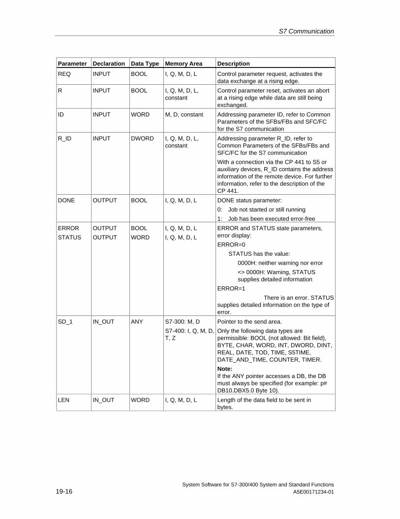
S7 Communication
System Software for S7-300/400 System and Standard Functions19-16 A5E00171234-01
Parameter Declaration Data Type Memory Area Description
REQ INPUT BOOL I, Q, M, D, L Control parameter request, activates thedata exchange at a rising edge.
R INPUT BOOL I, Q, M, D, L,constant
Control parameter reset, activates an abortat a rising edge while data are still beingexchanged.
ID INPUT WORD M, D, constant Addressing parameter ID, refer to CommonParameters of the SFBs/FBs and SFC/FCfor the S7 communication
R_ID INPUT DWORD I, Q, M, D, L,constant
Addressing parameter R_ID, refer toCommon Parameters of the SFBs/FBs andSFC/FC for the S7 communication
With a connection via the CP 441 to S5 orauxiliary devices, R_ID contains the addressinformation of the remote device. For furtherinformation, refer to the description of theCP 441.
DONE OUTPUT BOOL I, Q, M, D, L DONE status parameter:
0: Job not started or still running
1: Job has been executed error-free
ERROR
STATUS
OUTPUT
OUTPUT
BOOL
WORD
I, Q, M, D, L
I, Q, M, D, L
ERROR and STATUS state parameters,error display:
ERROR=0
STATUS has the value:
0000H: neither warning nor error
<> 0000H: Warning, STATUSsupplies detailed information
ERROR=1
There is an error. STATUSsupplies detailed information on the type oferror.
SD_1 IN_OUT ANY S7-300: M, D
S7-400: I, Q, M, D,T, Z
Pointer to the send area.
Only the following data types arepermissible: BOOL (not allowed: Bit field),BYTE, CHAR, WORD, INT, DWORD, DINT,REAL, DATE, TOD, TIME, S5TIME,DATE_AND_TIME, COUNTER, TIMER.
Note:If the ANY pointer accesses a DB, the DBmust always be specified (for example: p#DB10.DBX5.0 Byte 10).
LEN IN_OUT WORD I, Q, M, D, L Length of the data field to be sent inbytes.
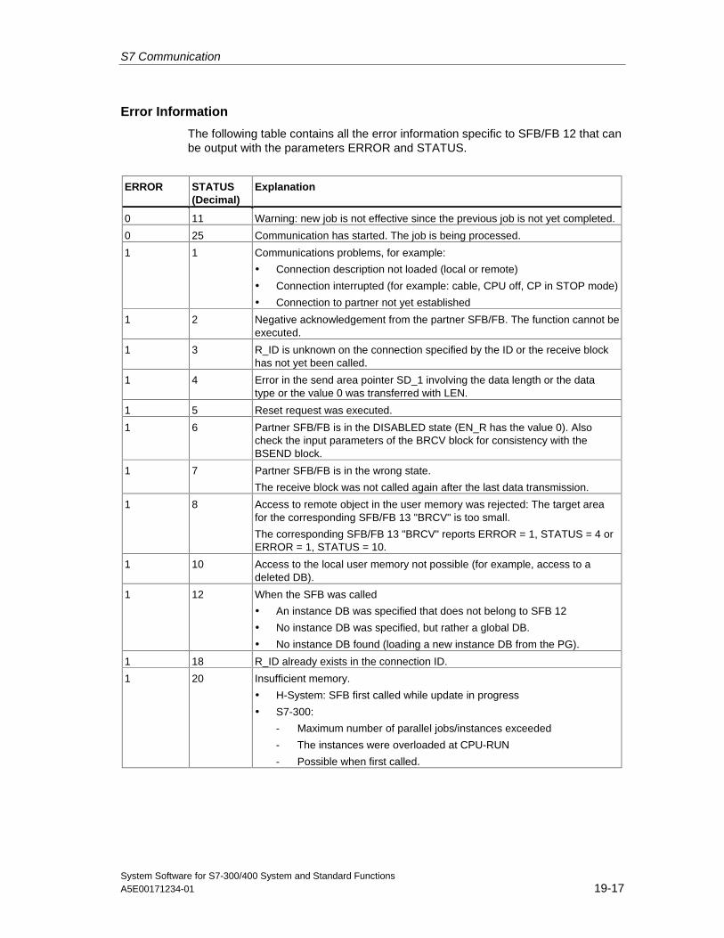
S7 Communication
System Software for S7-300/400 System and Standard FunctionsA5E00171234-01 19-17
Error Information
The following table contains all the error information specific to SFB/FB 12 that canbe output with the parameters ERROR and STATUS.
ERROR STATUS(Decimal)
Explanation
0 11 Warning: new job is not effective since the previous job is not yet completed.
0 25 Communication has started. The job is being processed.
1 1 Communications problems, for example:
• Connection description not loaded (local or remote)
• Connection interrupted (for example: cable, CPU off, CP in STOP mode)
• Connection to partner not yet established
1 2 Negative acknowledgement from the partner SFB/FB. The function cannot beexecuted.
1 3 R_ID is unknown on the connection specified by the ID or the receive blockhas not yet been called.
1 4 Error in the send area pointer SD_1 involving the data length or the datatype or the value 0 was transferred with LEN.
1 5 Reset request was executed.
1 6 Partner SFB/FB is in the DISABLED state (EN_R has the value 0). Alsocheck the input parameters of the BRCV block for consistency with theBSEND block.
1 7 Partner SFB/FB is in the wrong state.
The receive block was not called again after the last data transmission.
1 8 Access to remote object in the user memory was rejected: The target areafor the corresponding SFB/FB 13 "BRCV" is too small.
The corresponding SFB/FB 13 "BRCV" reports ERROR = 1, STATUS = 4 orERROR = 1, STATUS = 10.
1 10 Access to the local user memory not possible (for example, access to adeleted DB).
1 12 When the SFB was called
• An instance DB was specified that does not belong to SFB 12
• No instance DB was specified, but rather a global DB.
• No instance DB found (loading a new instance DB from the PG).
1 18 R_ID already exists in the connection ID.
1 20 Insufficient memory.
• H-System: SFB first called while update in progress
• S7-300:
- Maximum number of parallel jobs/instances exceeded
- The instances were overloaded at CPU-RUN
- Possible when first called.
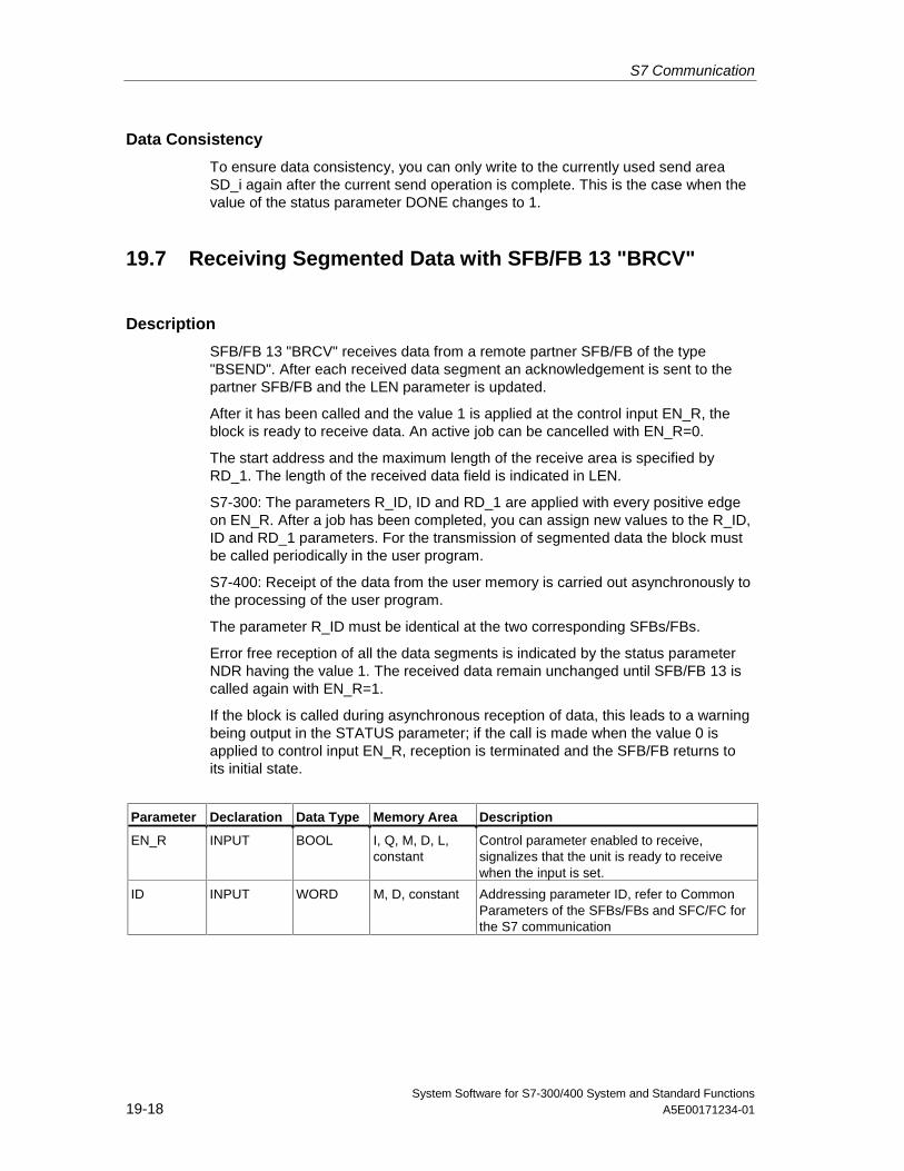
S7 Communication
System Software for S7-300/400 System and Standard Functions19-18 A5E00171234-01
Data Consistency
To ensure data consistency, you can only write to the currently used send areaSD_i again after the current send operation is complete. This is the case when thevalue of the status parameter DONE changes to 1.
19.7 Receiving Segmented Data with SFB/FB 13 "BRCV"
Description
SFB/FB 13 "BRCV" receives data from a remote partner SFB/FB of the type"BSEND". After each received data segment an acknowledgement is sent to thepartner SFB/FB and the LEN parameter is updated.
After it has been called and the value 1 is applied at the control input EN_R, theblock is ready to receive data. An active job can be cancelled with EN_R=0.
The start address and the maximum length of the receive area is specified byRD_1. The length of the received data field is indicated in LEN.
S7-300: The parameters R_ID, ID and RD_1 are applied with every positive edgeon EN_R. After a job has been completed, you can assign new values to the R_ID,ID and RD_1 parameters. For the transmission of segmented data the block mustbe called periodically in the user program.
S7-400: Receipt of the data from the user memory is carried out asynchronously tothe processing of the user program.
The parameter R_ID must be identical at the two corresponding SFBs/FBs.
Error free reception of all the data segments is indicated by the status parameterNDR having the value 1. The received data remain unchanged until SFB/FB 13 iscalled again with EN_R=1.
If the block is called during asynchronous reception of data, this leads to a warningbeing output in the STATUS parameter; if the call is made when the value 0 isapplied to control input EN_R, reception is terminated and the SFB/FB returns toits initial state.
Parameter Declaration Data Type Memory Area Description
EN_R INPUT BOOL I, Q, M, D, L,constant
Control parameter enabled to receive,signalizes that the unit is ready to receivewhen the input is set.
ID INPUT WORD M, D, constant Addressing parameter ID, refer to CommonParameters of the SFBs/FBs and SFC/FC forthe S7 communication
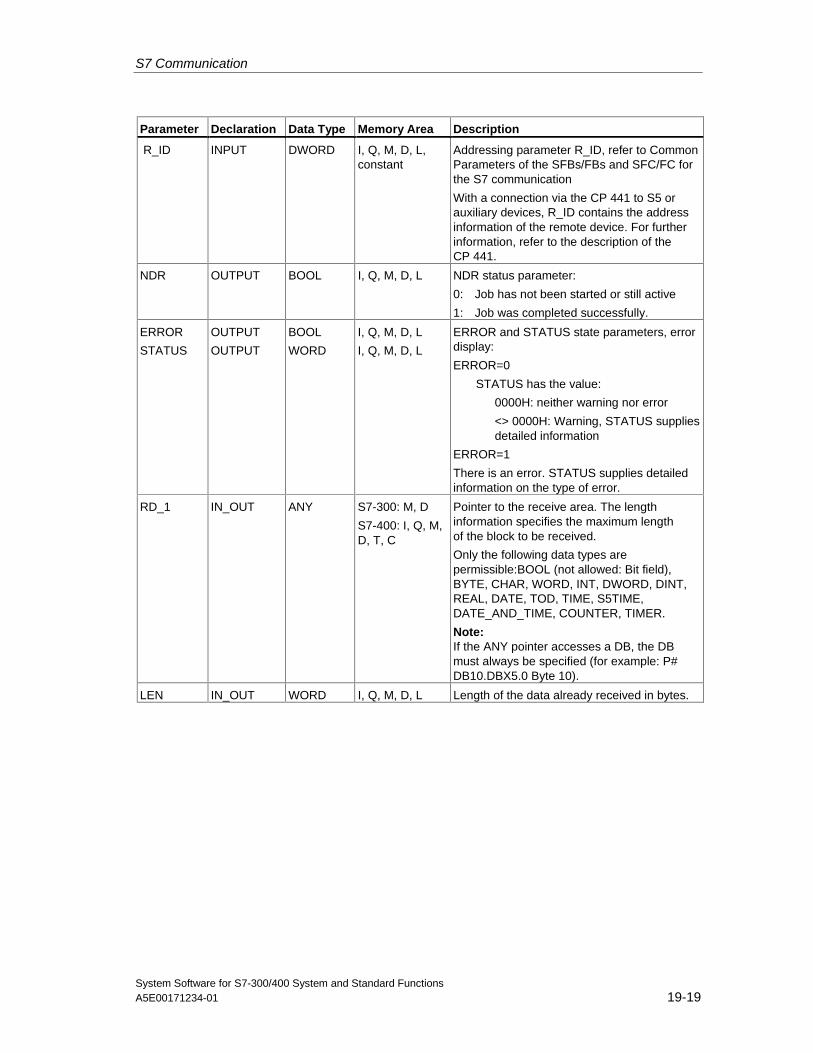
S7 Communication
System Software for S7-300/400 System and Standard FunctionsA5E00171234-01 19-19
Parameter Declaration Data Type Memory Area Description
R_ID INPUT DWORD I, Q, M, D, L,constant
Addressing parameter R_ID, refer to CommonParameters of the SFBs/FBs and SFC/FC forthe S7 communication
With a connection via the CP 441 to S5 orauxiliary devices, R_ID contains the addressinformation of the remote device. For furtherinformation, refer to the description of theCP 441.
NDR OUTPUT BOOL I, Q, M, D, L NDR status parameter:
0: Job has not been started or still active
1: Job was completed successfully.
ERROR
STATUS
OUTPUT
OUTPUT
BOOL
WORD
I, Q, M, D, L
I, Q, M, D, L
ERROR and STATUS state parameters, errordisplay:
ERROR=0
STATUS has the value:
0000H: neither warning nor error
<> 0000H: Warning, STATUS suppliesdetailed information
ERROR=1
There is an error. STATUS supplies detailedinformation on the type of error.
RD_1 IN_OUT ANY S7-300: M, D
S7-400: I, Q, M,D, T, C
Pointer to the receive area. The lengthinformation specifies the maximum lengthof the block to be received.
Only the following data types arepermissible:BOOL (not allowed: Bit field),BYTE, CHAR, WORD, INT, DWORD, DINT,REAL, DATE, TOD, TIME, S5TIME,DATE_AND_TIME, COUNTER, TIMER.
Note:If the ANY pointer accesses a DB, the DBmust always be specified (for example: P#DB10.DBX5.0 Byte 10).
LEN IN_OUT WORD I, Q, M, D, L Length of the data already received in bytes.
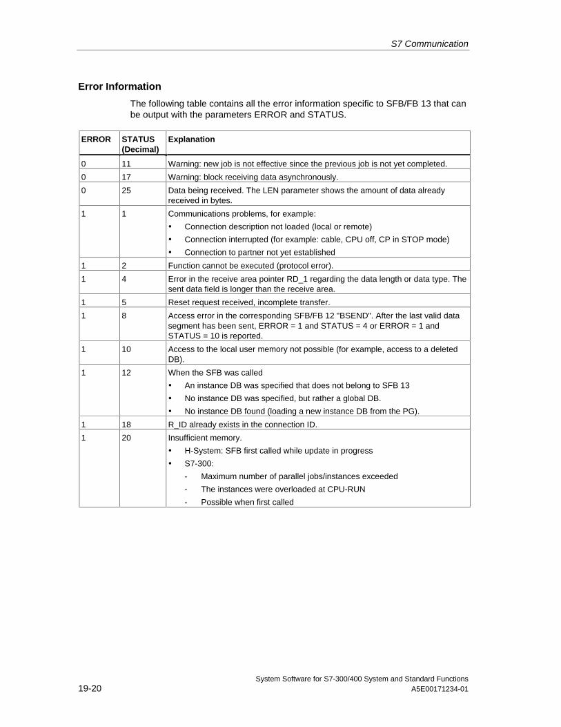
S7 Communication
System Software for S7-300/400 System and Standard Functions19-20 A5E00171234-01
Error Information
The following table contains all the error information specific to SFB/FB 13 that canbe output with the parameters ERROR and STATUS.
ERROR STATUS(Decimal)
Explanation
0 11 Warning: new job is not effective since the previous job is not yet completed.
0 17 Warning: block receiving data asynchronously.
0 25 Data being received. The LEN parameter shows the amount of data alreadyreceived in bytes.
1 1 Communications problems, for example:
• Connection description not loaded (local or remote)
• Connection interrupted (for example: cable, CPU off, CP in STOP mode)
• Connection to partner not yet established
1 2 Function cannot be executed (protocol error).
1 4 Error in the receive area pointer RD_1 regarding the data length or data type. Thesent data field is longer than the receive area.
1 5 Reset request received, incomplete transfer.
1 8 Access error in the corresponding SFB/FB 12 "BSEND". After the last valid datasegment has been sent, ERROR = 1 and STATUS = 4 or ERROR = 1 andSTATUS = 10 is reported.
1 10 Access to the local user memory not possible (for example, access to a deletedDB).
1 12 When the SFB was called
• An instance DB was specified that does not belong to SFB 13
• No instance DB was specified, but rather a global DB.
• No instance DB found (loading a new instance DB from the PG).
1 18 R_ID already exists in the connection ID.
1 20 Insufficient memory.
• H-System: SFB first called while update in progress
• S7-300:
- Maximum number of parallel jobs/instances exceeded
- The instances were overloaded at CPU-RUN
- Possible when first called
S7 Communication
System Software for S7-300/400 System and Standard FunctionsA5E00171234-01 19-21
Data Consistency
The data are received consistently if you remember the following point:
Evaluate the last used receive areas (RD_1) completely before you call the blockagain with the value 1 at control input EN_R).
Special Case for Receiving Data (S7-400 only)
If a receiving CPU with a BRCV block ready to accept data (that is, a call withEN_R = 1 has already been made) goes into STOP mode before thecorresponding send block has sent the first data segment for the job, the followingwill occur:
• The data in the first job after the receiving CPU has gone into STOP mode arefully entered in the receive area.
• The partner SFB "BSEND" receives a positive acknowledgement.
• Any additional BSEND jobs can no longer be accepted by a receiving CPU inSTOP mode.
• As long as the CPU remains in STOP mode, both NDR and LEN have thevalue 0.
To prevent information about the received data from being lost, you must perform ahot restart of the receiving CPU and call SFB 13 "BRCV" with EN_R = 1.
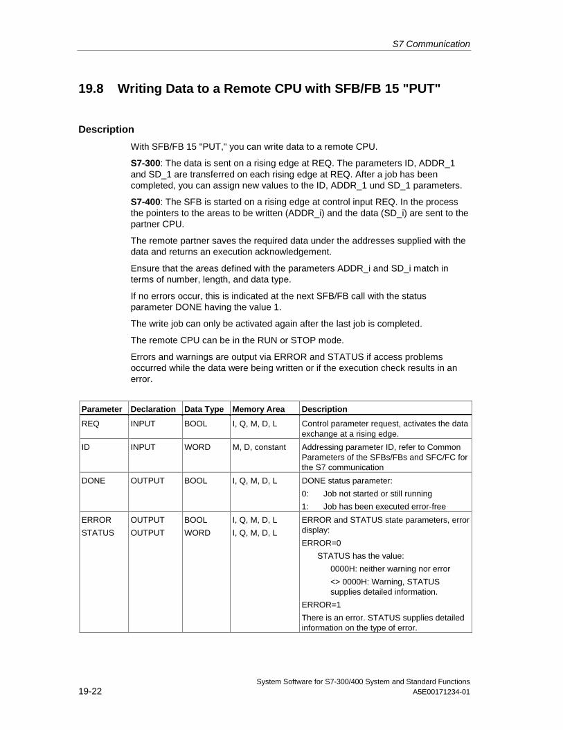
S7 Communication
System Software for S7-300/400 System and Standard Functions19-22 A5E00171234-01
19.8 Writing Data to a Remote CPU with SFB/FB 15 "PUT"
Description
With SFB/FB 15 "PUT," you can write data to a remote CPU.
S7-300: The data is sent on a rising edge at REQ. The parameters ID, ADDR_1and SD_1 are transferred on each rising edge at REQ. After a job has beencompleted, you can assign new values to the ID, ADDR_1 und SD_1 parameters.
S7-400: The SFB is started on a rising edge at control input REQ. In the processthe pointers to the areas to be written (ADDR_i) and the data (SD_i) are sent to thepartner CPU.
The remote partner saves the required data under the addresses supplied with thedata and returns an execution acknowledgement.
Ensure that the areas defined with the parameters ADDR_i and SD_i match interms of number, length, and data type.
If no errors occur, this is indicated at the next SFB/FB call with the statusparameter DONE having the value 1.
The write job can only be activated again after the last job is completed.
The remote CPU can be in the RUN or STOP mode.
Errors and warnings are output via ERROR and STATUS if access problemsoccurred while the data were being written or if the execution check results in anerror.
Parameter Declaration Data Type Memory Area Description
REQ INPUT BOOL I, Q, M, D, L Control parameter request, activates the dataexchange at a rising edge.
ID INPUT WORD M, D, constant Addressing parameter ID, refer to CommonParameters of the SFBs/FBs and SFC/FC forthe S7 communication
DONE OUTPUT BOOL I, Q, M, D, L DONE status parameter:
0: Job not started or still running
1: Job has been executed error-free
ERROR
STATUS
OUTPUT
OUTPUT
BOOL
WORD
I, Q, M, D, L
I, Q, M, D, L
ERROR and STATUS state parameters, errordisplay:
ERROR=0
STATUS has the value:
0000H: neither warning nor error
<> 0000H: Warning, STATUSsupplies detailed information.
ERROR=1
There is an error. STATUS supplies detailedinformation on the type of error.
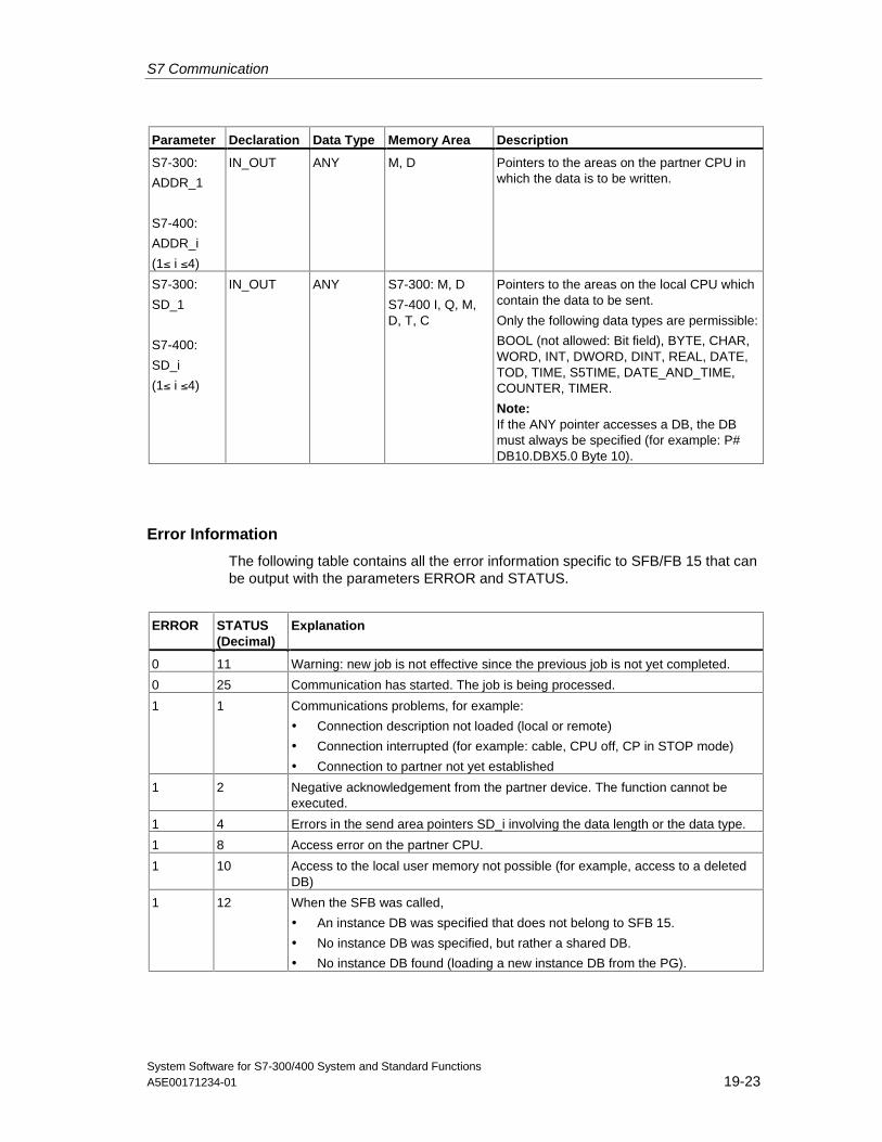
S7 Communication
System Software for S7-300/400 System and Standard FunctionsA5E00171234-01 19-23
Parameter Declaration Data Type Memory Area Description
S7-300:
ADDR_1
S7-400:
ADDR_i
(1≤ i ≤4)
IN_OUT ANY M, D Pointers to the areas on the partner CPU inwhich the data is to be written.
S7-300:
SD_1
S7-400:
SD_i
(1≤ i ≤4)
IN_OUT ANY S7-300: M, D
S7-400 I, Q, M,D, T, C
Pointers to the areas on the local CPU whichcontain the data to be sent.
Only the following data types are permissible:
BOOL (not allowed: Bit field), BYTE, CHAR,WORD, INT, DWORD, DINT, REAL, DATE,TOD, TIME, S5TIME, DATE_AND_TIME,COUNTER, TIMER.
Note:If the ANY pointer accesses a DB, the DBmust always be specified (for example: P#DB10.DBX5.0 Byte 10).
Error Information
The following table contains all the error information specific to SFB/FB 15 that canbe output with the parameters ERROR and STATUS.
ERROR STATUS(Decimal)
Explanation
0 11 Warning: new job is not effective since the previous job is not yet completed.
0 25 Communication has started. The job is being processed.
1 1 Communications problems, for example:
• Connection description not loaded (local or remote)
• Connection interrupted (for example: cable, CPU off, CP in STOP mode)
• Connection to partner not yet established
1 2 Negative acknowledgement from the partner device. The function cannot beexecuted.
1 4 Errors in the send area pointers SD_i involving the data length or the data type.
1 8 Access error on the partner CPU.
1 10 Access to the local user memory not possible (for example, access to a deletedDB)
1 12 When the SFB was called,
• An instance DB was specified that does not belong to SFB 15.
• No instance DB was specified, but rather a shared DB.
• No instance DB found (loading a new instance DB from the PG).
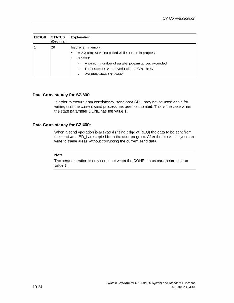
S7 Communication
System Software for S7-300/400 System and Standard Functions19-24 A5E00171234-01
ERROR STATUS(Decimal)
Explanation
1 20 Insufficient memory.
• H-System: SFB first called while update in progress
• S7-300:
- Maximum number of parallel jobs/instances exceeded
- The instances were overloaded at CPU-RUN
- Possible when first called
Data Consistency for S7-300
In order to ensure data consistency, send area SD_I may not be used again forwriting until the current send process has been completed. This is the case whenthe state parameter DONE has the value 1.
Data Consistency for S7-400:
When a send operation is activated (rising edge at REQ) the data to be sent fromthe send area SD_i are copied from the user program. After the block call, you canwrite to these areas without corrupting the current send data.
Note
The send operation is only complete when the DONE status parameter has thevalue 1.
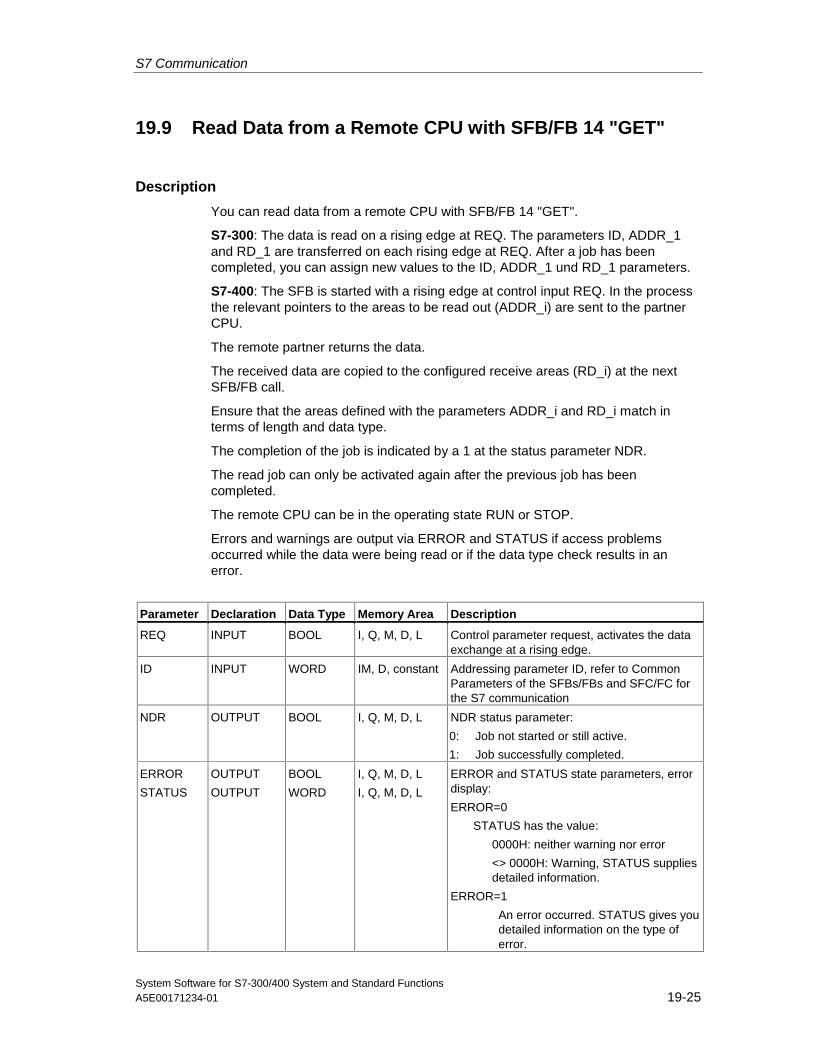
S7 Communication
System Software for S7-300/400 System and Standard FunctionsA5E00171234-01 19-25
19.9 Read Data from a Remote CPU with SFB/FB 14 "GET"
Description
You can read data from a remote CPU with SFB/FB 14 "GET".
S7-300: The data is read on a rising edge at REQ. The parameters ID, ADDR_1and RD_1 are transferred on each rising edge at REQ. After a job has beencompleted, you can assign new values to the ID, ADDR_1 und RD_1 parameters.
S7-400: The SFB is started with a rising edge at control input REQ. In the processthe relevant pointers to the areas to be read out (ADDR_i) are sent to the partnerCPU.
The remote partner returns the data.
The received data are copied to the configured receive areas (RD_i) at the nextSFB/FB call.
Ensure that the areas defined with the parameters ADDR_i and RD_i match interms of length and data type.
The completion of the job is indicated by a 1 at the status parameter NDR.
The read job can only be activated again after the previous job has beencompleted.
The remote CPU can be in the operating state RUN or STOP.
Errors and warnings are output via ERROR and STATUS if access problemsoccurred while the data were being read or if the data type check results in anerror.
Parameter Declaration Data Type Memory Area Description
REQ INPUT BOOL I, Q, M, D, L Control parameter request, activates the dataexchange at a rising edge.
ID INPUT WORD IM, D, constant Addressing parameter ID, refer to CommonParameters of the SFBs/FBs and SFC/FC forthe S7 communication
NDR OUTPUT BOOL I, Q, M, D, L NDR status parameter:
0: Job not started or still active.
1: Job successfully completed.
ERROR
STATUS
OUTPUT
OUTPUT
BOOL
WORD
I, Q, M, D, L
I, Q, M, D, L
ERROR and STATUS state parameters, errordisplay:
ERROR=0
STATUS has the value:
0000H: neither warning nor error
<> 0000H: Warning, STATUS suppliesdetailed information.
ERROR=1
An error occurred. STATUS gives youdetailed information on the type of error.
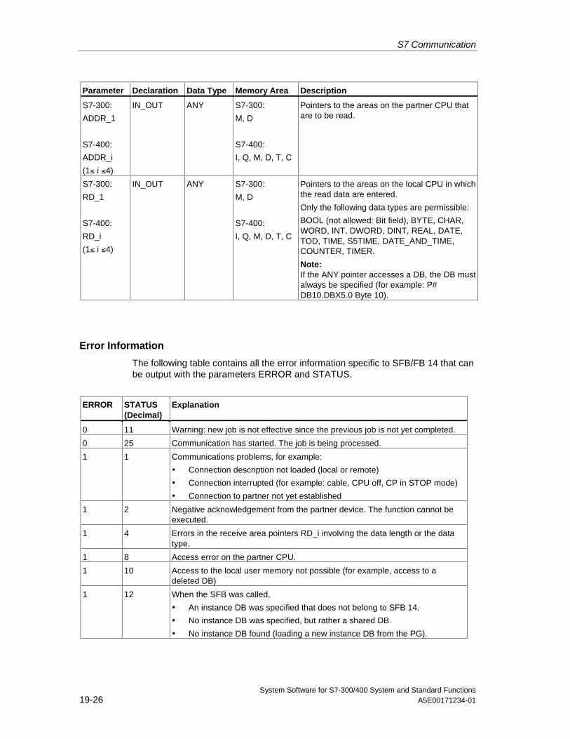
S7 Communication
System Software for S7-300/400 System and Standard Functions19-26 A5E00171234-01
Parameter Declaration Data Type Memory Area Description
S7-300:
ADDR_1
S7-400:
ADDR_i
(1≤ i ≤4)
IN_OUT ANY S7-300:
M, D
S7-400:
I, Q, M, D, T, C
Pointers to the areas on the partner CPU thatare to be read.
S7-300:
RD_1
S7-400:
RD_i
(1≤ i ≤4)
IN_OUT ANY S7-300:
M, D
S7-400:
I, Q, M, D, T, C
Pointers to the areas on the local CPU in whichthe read data are entered.
Only the following data types are permissible:
BOOL (not allowed: Bit field), BYTE, CHAR,WORD, INT, DWORD, DINT, REAL, DATE,TOD, TIME, S5TIME, DATE_AND_TIME,COUNTER, TIMER.
Note:If the ANY pointer accesses a DB, the DB mustalways be specified (for example: P#DB10.DBX5.0 Byte 10).
Error Information
The following table contains all the error information specific to SFB/FB 14 that canbe output with the parameters ERROR and STATUS.
ERROR STATUS(Decimal)
Explanation
0 11 Warning: new job is not effective since the previous job is not yet completed.
0 25 Communication has started. The job is being processed.
1 1 Communications problems, for example:
• Connection description not loaded (local or remote)
• Connection interrupted (for example: cable, CPU off, CP in STOP mode)
• Connection to partner not yet established
1 2 Negative acknowledgement from the partner device. The function cannot beexecuted.
1 4 Errors in the receive area pointers RD_i involving the data length or the datatype.
1 8 Access error on the partner CPU.
1 10 Access to the local user memory not possible (for example, access to adeleted DB)
1 12 When the SFB was called,
• An instance DB was specified that does not belong to SFB 14.
• No instance DB was specified, but rather a shared DB.
• No instance DB found (loading a new instance DB from the PG).
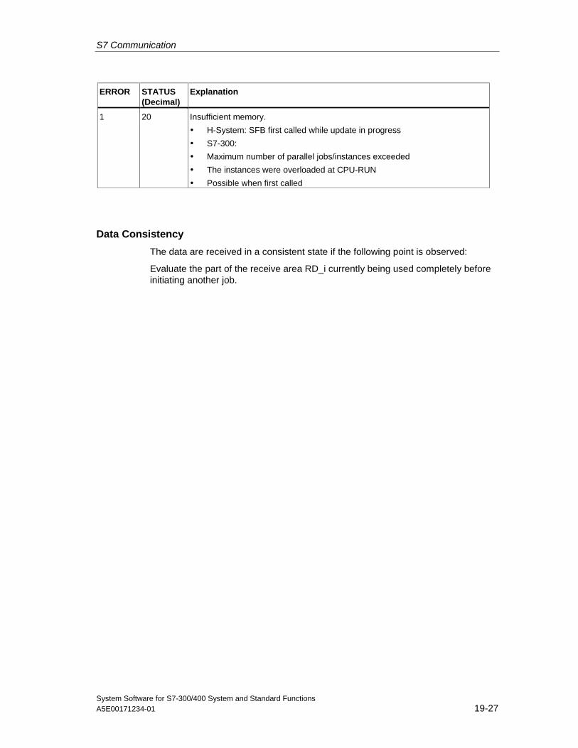
S7 Communication
System Software for S7-300/400 System and Standard FunctionsA5E00171234-01 19-27
ERROR STATUS(Decimal)
Explanation
1 20 Insufficient memory.
• H-System: SFB first called while update in progress
• S7-300:
• Maximum number of parallel jobs/instances exceeded
• The instances were overloaded at CPU-RUN
• Possible when first called
Data Consistency
The data are received in a consistent state if the following point is observed:
Evaluate the part of the receive area RD_i currently being used completely beforeinitiating another job.
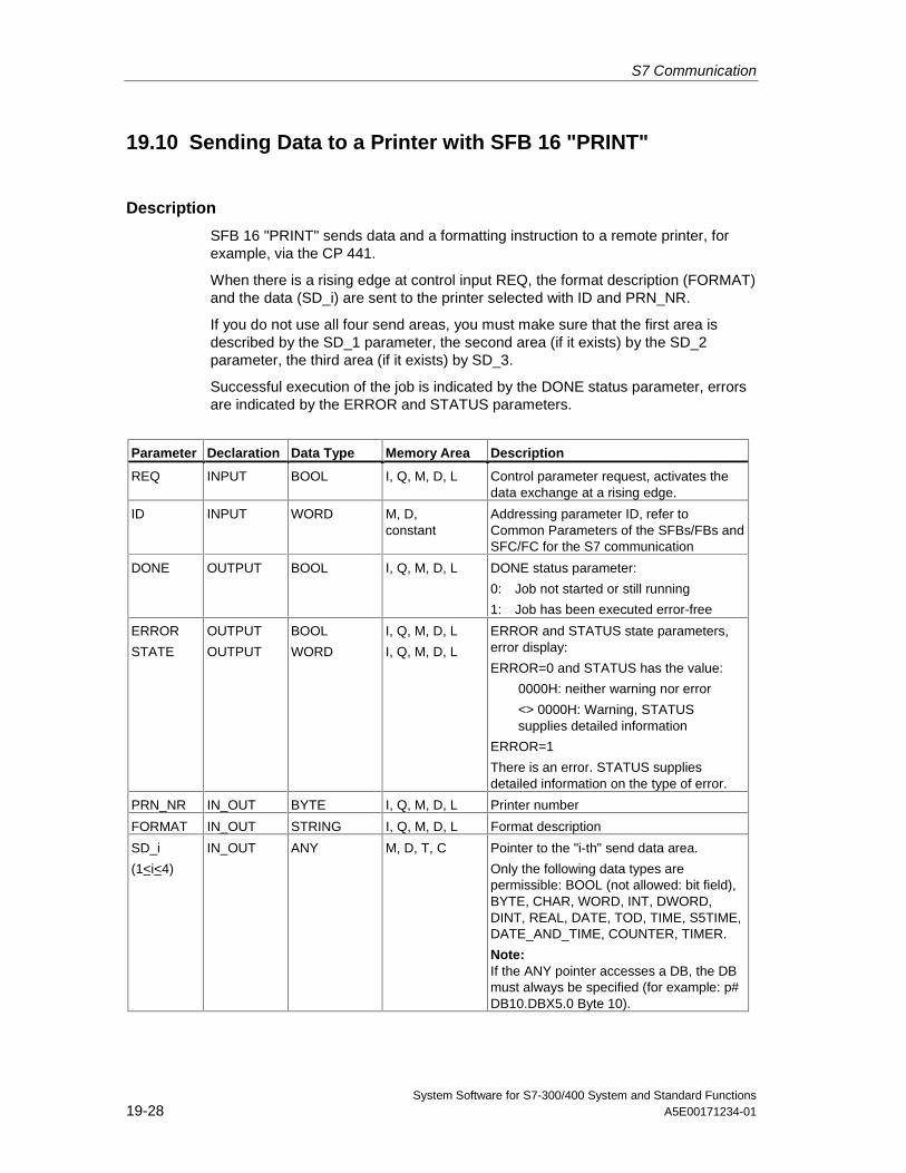
S7 Communication
System Software for S7-300/400 System and Standard Functions19-28 A5E00171234-01
19.10 Sending Data to a Printer with SFB 16 "PRINT"
Description
SFB 16 "PRINT" sends data and a formatting instruction to a remote printer, forexample, via the CP 441.
When there is a rising edge at control input REQ, the format description (FORMAT)and the data (SD_i) are sent to the printer selected with ID and PRN_NR.
If you do not use all four send areas, you must make sure that the first area isdescribed by the SD_1 parameter, the second area (if it exists) by the SD_2parameter, the third area (if it exists) by SD_3.
Successful execution of the job is indicated by the DONE status parameter, errorsare indicated by the ERROR and STATUS parameters.
Parameter Declaration Data Type Memory Area Description
REQ INPUT BOOL I, Q, M, D, L Control parameter request, activates thedata exchange at a rising edge.
ID INPUT WORD M, D,constant
Addressing parameter ID, refer toCommon Parameters of the SFBs/FBs andSFC/FC for the S7 communication
DONE OUTPUT BOOL I, Q, M, D, L DONE status parameter:
0: Job not started or still running
1: Job has been executed error-free
ERROR
STATE
OUTPUT
OUTPUT
BOOL
WORD
I, Q, M, D, L
I, Q, M, D, L
ERROR and STATUS state parameters,error display:
ERROR=0 and STATUS has the value:
0000H: neither warning nor error
<> 0000H: Warning, STATUSsupplies detailed information
ERROR=1
There is an error. STATUS suppliesdetailed information on the type of error.
PRN_NR IN_OUT BYTE I, Q, M, D, L Printer number
FORMAT IN_OUT STRING I, Q, M, D, L Format description
SD_i
(1<i< 4)
IN_OUT ANY M, D, T, C Pointer to the "i-th" send data area.
Only the following data types arepermissible: BOOL (not allowed: bit field),BYTE, CHAR, WORD, INT, DWORD,DINT, REAL, DATE, TOD, TIME, S5TIME,DATE_AND_TIME, COUNTER, TIMER.
Note:If the ANY pointer accesses a DB, the DBmust always be specified (for example: p#DB10.DBX5.0 Byte 10).
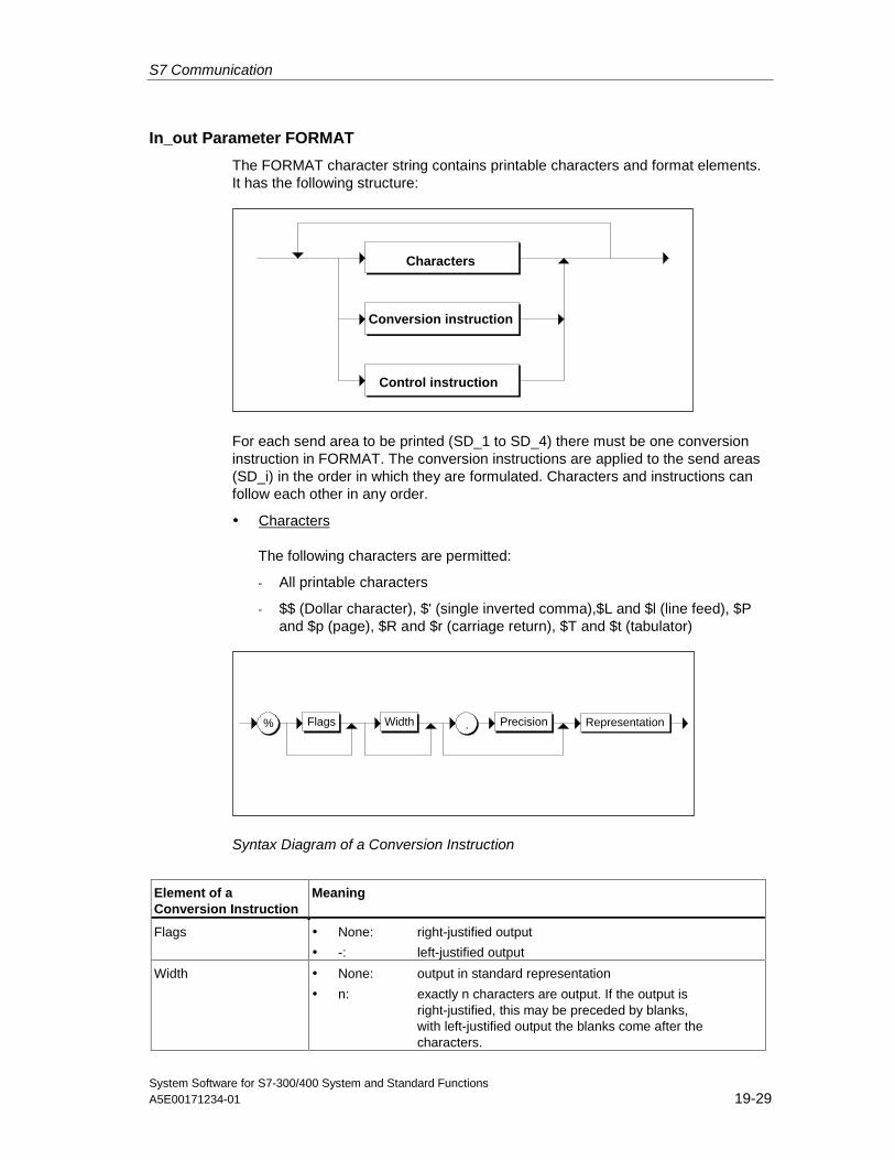
S7 Communication
System Software for S7-300/400 System and Standard FunctionsA5E00171234-01 19-29
In_out Parameter FORMAT
The FORMAT character string contains printable characters and format elements.It has the following structure:
Conversion instruction
Characters
Control instruction
For each send area to be printed (SD_1 to SD_4) there must be one conversioninstruction in FORMAT. The conversion instructions are applied to the send areas(SD_i) in the order in which they are formulated. Characters and instructions canfollow each other in any order.
• Characters
The following characters are permitted:
- All printable characters
- $$ (Dollar character), $' (single inverted comma),$L and $l (line feed), $Pand $p (page), $R and $r (carriage return), $T and $t (tabulator)
% .Flags RepresentationWidth Precision
Syntax Diagram of a Conversion Instruction
Element of aConversion Instruction
Meaning
Flags • None: right-justified output
• -: left-justified output
Width • None: output in standard representation
• n: exactly n characters are output. If the output isright-justified, this may be preceded by blanks,with left-justified output the blanks come after thecharacters.
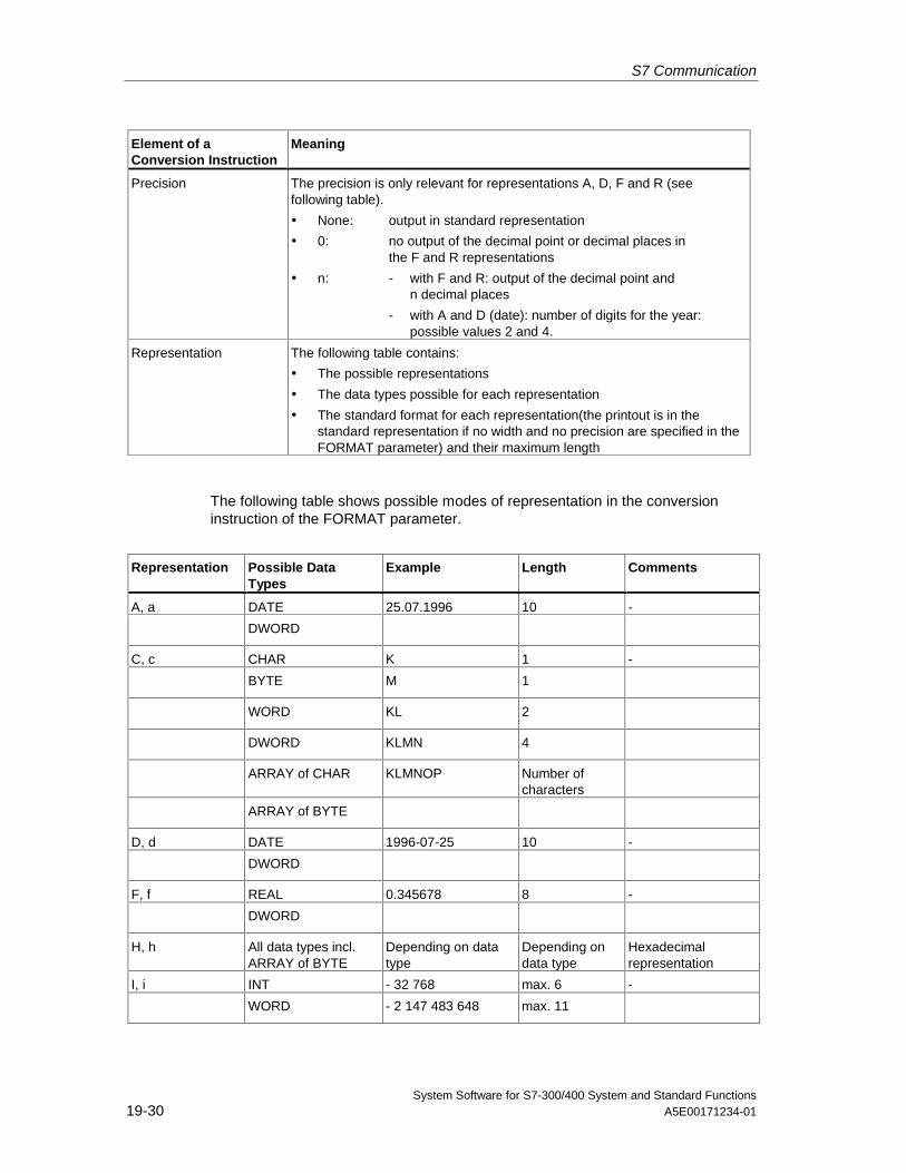
S7 Communication
System Software for S7-300/400 System and Standard Functions19-30 A5E00171234-01
Element of aConversion Instruction
Meaning
Precision The precision is only relevant for representations A, D, F and R (seefollowing table).
• None: output in standard representation
• 0: no output of the decimal point or decimal places inthe F and R representations
• n: - with F and R: output of the decimal point andn decimal places
- with A and D (date): number of digits for the year:possible values 2 and 4.
Representation The following table contains:
• The possible representations
• The data types possible for each representation
• The standard format for each representation(the printout is in thestandard representation if no width and no precision are specified in theFORMAT parameter) and their maximum length
The following table shows possible modes of representation in the conversioninstruction of the FORMAT parameter.
Representation Possible DataTypes
Example Length Comments
A, a DATE 25.07.1996 10 -
DWORD
C, c CHAR K 1 -
BYTE M 1
WORD KL 2
DWORD KLMN 4
ARRAY of CHAR KLMNOP Number ofcharacters
ARRAY of BYTE
D, d DATE 1996-07-25 10 -
DWORD
F, f REAL 0.345678 8 -
DWORD
H, h All data types incl.ARRAY of BYTE
Depending on datatype
Depending ondata type
Hexadecimalrepresentation
I, i INT - 32 768 max. 6 -
WORD - 2 147 483 648 max. 11
S7 Communication
System Software for S7-300/400 System and Standard FunctionsA5E00171234-01 19-31
Representation Possible DataTypes
Example Length Comments
N, n WORD Text output - The correspondingsend area SD_icontains a reference(number) to a text tobe printed. The text ison the module (forexample, CP 441)that creates aprintable string. Ifno text is foundunder the specifiednumber, ****** isoutput.
R, r REAL 0.12E-04 8 -
DWORD
S, s STRING Text output -
T, t TIME 2d_3h_10m_5s_250ms
max. 21 If an error occurs,****** is output.
DWORD
U, u BYTE 255 max. 3 -
WORD 65 535 max. 5
DWORD 4 294 967 295 max. 10
X, x BOOL 1 1 -
BYTE 101 .. 8
WORD 101 .. 16
DWORD 101 .. 32
Z, z TIME_OF_DAY(TOD)
15:38:59.874 12 -
At the points in this table at which a maximum length is specified for therepresentation, the actual length can of course be shorter.
Note
With the data types C and S, the following points depend on the printer being used:
• which characters can be printed
• what the printer prints for non-printable characters, unless the printer driver hasa conversion table for these characters.
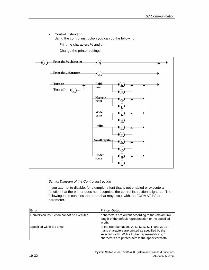
S7 Communication
System Software for S7-300/400 System and Standard Functions19-32 A5E00171234-01
• Control InstructionUsing the control instruction you can do the following:
- Print the characters % and \
- Change the printer settings.
Underscore u
U
\
Small capitalsk
K
Italicsi
I
Wideprint e
E
Narrowprint
Boldface
Print the % character
Print the \ character
Turn on
Turn off
\
%
-
b
B
c
C
Syntax Diagram of the Control Instruction
If you attempt to disable, for example, a font that is not enabled or execute afunction that the printer does not recognize, the control instruction is ignored. Thefollowing table contains the errors that may occur with the FORMAT in/outparameter.
Error Printer Output
Conversion instruction cannot be executed * characters are output according to the (maximum)length of the default representation or the specifiedwidth.
Specified width too small In the representations A, C, D, N, S, T, and Z, asmany characters are printed as specified by theselected width. With all other representations, *characters are printed across the specified width.
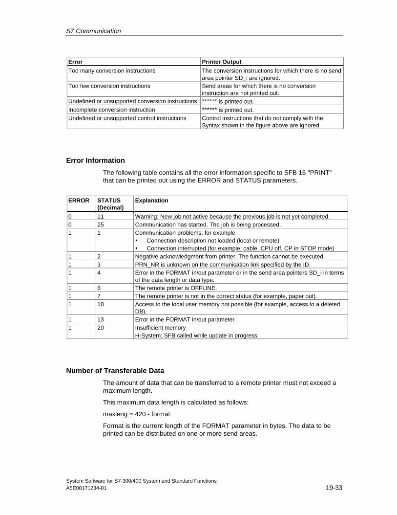
S7 Communication
System Software for S7-300/400 System and Standard FunctionsA5E00171234-01 19-33
Error Printer Output
Too many conversion instructions The conversion instructions for which there is no sendarea pointer SD_i are ignored.
Too few conversion instructions Send areas for which there is no conversioninstruction are not printed out.
Undefined or unsupported conversion instructions ****** is printed out.Incomplete conversion instruction ****** is printed out.Undefined or unsupported control instructions Control instructions that do not comply with the
Syntax shown in the figure above are ignored.
Error Information
The following table contains all the error information specific to SFB 16 "PRINT"that can be printed out using the ERROR and STATUS parameters.
ERROR STATUS(Decimal)
Explanation
0 11 Warning: New job not active because the previous job is not yet completed.0 25 Communication has started. The job is being processed.1 1 Communication problems, for example
• Connection description not loaded (local or remote)• Connection interrupted (for example, cable, CPU off, CP in STOP mode)
1 2 Negative acknowledgment from printer. The function cannot be executed.1 3 PRN_NR is unknown on the communication link specified by the ID.1 4 Error in the FORMAT in/out parameter or in the send area pointers SD_i in terms
of the data length or data type.1 6 The remote printer is OFFLINE.1 7 The remote printer is not in the correct status (for example, paper out).1 10 Access to the local user memory not possible (for example, access to a deleted
DB).1 13 Error in the FORMAT in/out parameter1 20 Insufficient memory
H-System: SFB called while update in progress
Number of Transferable Data
The amount of data that can be transferred to a remote printer must not exceed amaximum length.
This maximum data length is calculated as follows:
maxleng = 420 - format
Format is the current length of the FORMAT parameter in bytes. The data to beprinted can be distributed on one or more send areas.
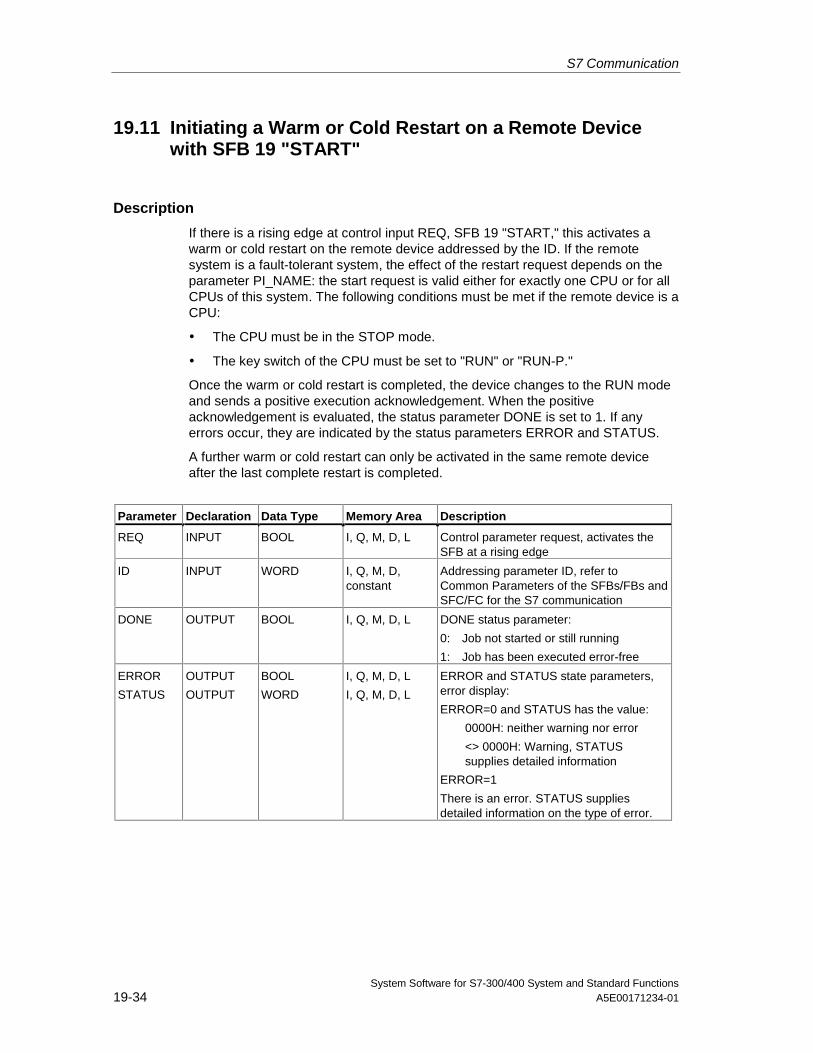
S7 Communication
System Software for S7-300/400 System and Standard Functions19-34 A5E00171234-01
19.11 Initiating a Warm or Cold Restart on a Remote Devicewith SFB 19 "START"
Description
If there is a rising edge at control input REQ, SFB 19 "START," this activates awarm or cold restart on the remote device addressed by the ID. If the remotesystem is a fault-tolerant system, the effect of the restart request depends on theparameter PI_NAME: the start request is valid either for exactly one CPU or for allCPUs of this system. The following conditions must be met if the remote device is aCPU:
• The CPU must be in the STOP mode.
• The key switch of the CPU must be set to "RUN" or "RUN-P."
Once the warm or cold restart is completed, the device changes to the RUN modeand sends a positive execution acknowledgement. When the positiveacknowledgement is evaluated, the status parameter DONE is set to 1. If anyerrors occur, they are indicated by the status parameters ERROR and STATUS.
A further warm or cold restart can only be activated in the same remote deviceafter the last complete restart is completed.
Parameter Declaration Data Type Memory Area Description
REQ INPUT BOOL I, Q, M, D, L Control parameter request, activates theSFB at a rising edge
ID INPUT WORD I, Q, M, D,constant
Addressing parameter ID, refer toCommon Parameters of the SFBs/FBs andSFC/FC for the S7 communication
DONE OUTPUT BOOL I, Q, M, D, L DONE status parameter:
0: Job not started or still running
1: Job has been executed error-free
ERROR
STATUS
OUTPUT
OUTPUT
BOOL
WORD
I, Q, M, D, L
I, Q, M, D, L
ERROR and STATUS state parameters,error display:
ERROR=0 and STATUS has the value:
0000H: neither warning nor error
<> 0000H: Warning, STATUSsupplies detailed information
ERROR=1
There is an error. STATUS suppliesdetailed information on the type of error.
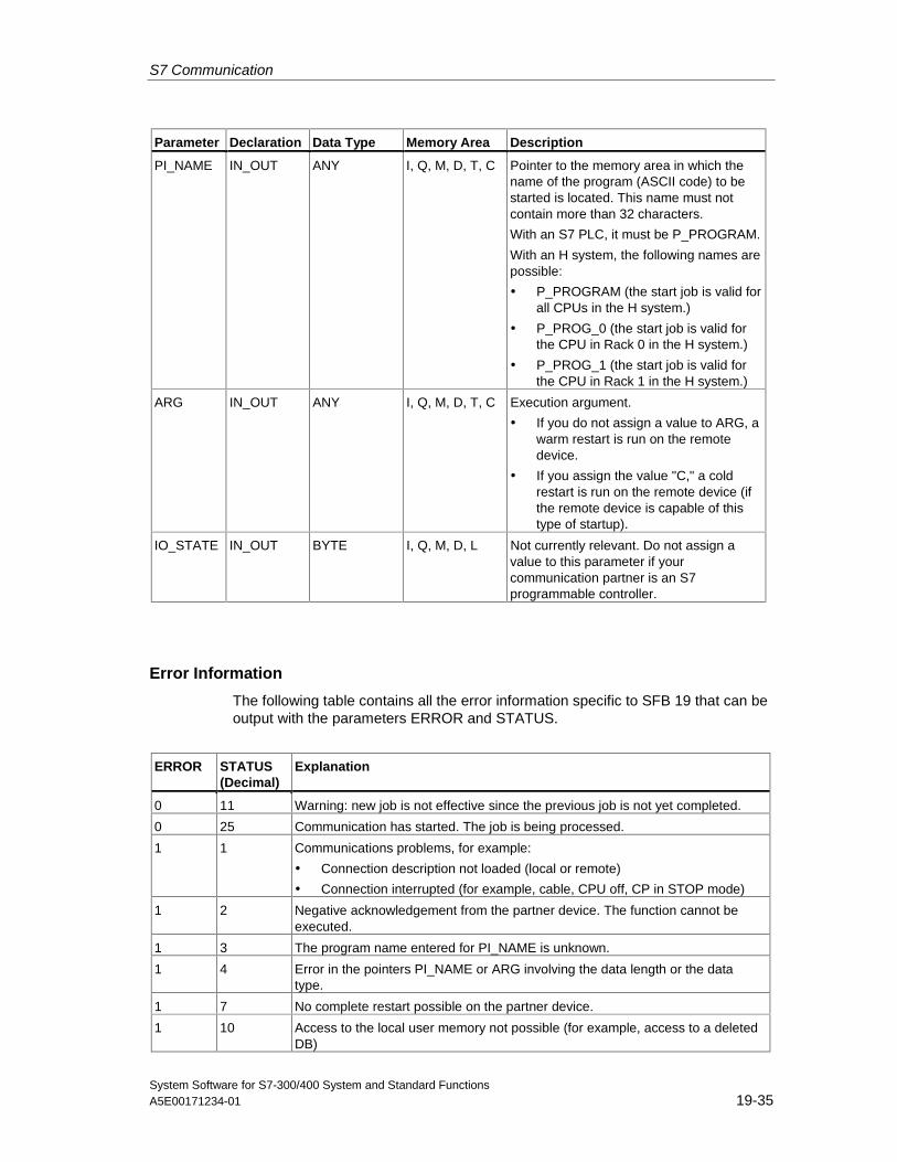
S7 Communication
System Software for S7-300/400 System and Standard FunctionsA5E00171234-01 19-35
Parameter Declaration Data Type Memory Area Description
PI_NAME IN_OUT ANY I, Q, M, D, T, C Pointer to the memory area in which thename of the program (ASCII code) to bestarted is located. This name must notcontain more than 32 characters.
With an S7 PLC, it must be P_PROGRAM.
With an H system, the following names arepossible:
• P_PROGRAM (the start job is valid forall CPUs in the H system.)
• P_PROG_0 (the start job is valid forthe CPU in Rack 0 in the H system.)
• P_PROG_1 (the start job is valid forthe CPU in Rack 1 in the H system.)
ARG IN_OUT ANY I, Q, M, D, T, C Execution argument.
• If you do not assign a value to ARG, awarm restart is run on the remotedevice.
• If you assign the value "C," a coldrestart is run on the remote device (ifthe remote device is capable of thistype of startup).
IO_STATE IN_OUT BYTE I, Q, M, D, L Not currently relevant. Do not assign avalue to this parameter if yourcommunication partner is an S7programmable controller.
Error Information
The following table contains all the error information specific to SFB 19 that can beoutput with the parameters ERROR and STATUS.
ERROR STATUS(Decimal)
Explanation
0 11 Warning: new job is not effective since the previous job is not yet completed.
0 25 Communication has started. The job is being processed.
1 1 Communications problems, for example:
• Connection description not loaded (local or remote)
• Connection interrupted (for example, cable, CPU off, CP in STOP mode)
1 2 Negative acknowledgement from the partner device. The function cannot beexecuted.
1 3 The program name entered for PI_NAME is unknown.
1 4 Error in the pointers PI_NAME or ARG involving the data length or the datatype.
1 7 No complete restart possible on the partner device.
1 10 Access to the local user memory not possible (for example, access to a deletedDB)
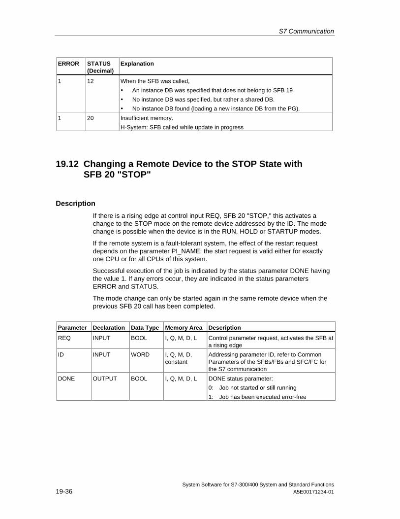
S7 Communication
System Software for S7-300/400 System and Standard Functions19-36 A5E00171234-01
ERROR STATUS(Decimal)
Explanation
1 12 When the SFB was called,
• An instance DB was specified that does not belong to SFB 19
• No instance DB was specified, but rather a shared DB.
• No instance DB found (loading a new instance DB from the PG).
1 20 Insufficient memory.
H-System: SFB called while update in progress
19.12 Changing a Remote Device to the STOP State withSFB 20 "STOP"
Description
If there is a rising edge at control input REQ, SFB 20 "STOP," this activates achange to the STOP mode on the remote device addressed by the ID. The modechange is possible when the device is in the RUN, HOLD or STARTUP modes.
If the remote system is a fault-tolerant system, the effect of the restart requestdepends on the parameter PI_NAME: the start request is valid either for exactlyone CPU or for all CPUs of this system.
Successful execution of the job is indicated by the status parameter DONE havingthe value 1. If any errors occur, they are indicated in the status parametersERROR and STATUS.
The mode change can only be started again in the same remote device when theprevious SFB 20 call has been completed.
Parameter Declaration Data Type Memory Area Description
REQ INPUT BOOL I, Q, M, D, L Control parameter request, activates the SFB ata rising edge
ID INPUT WORD I, Q, M, D,constant
Addressing parameter ID, refer to CommonParameters of the SFBs/FBs and SFC/FC forthe S7 communication
DONE OUTPUT BOOL I, Q, M, D, L DONE status parameter:
0: Job not started or still running
1: Job has been executed error-free
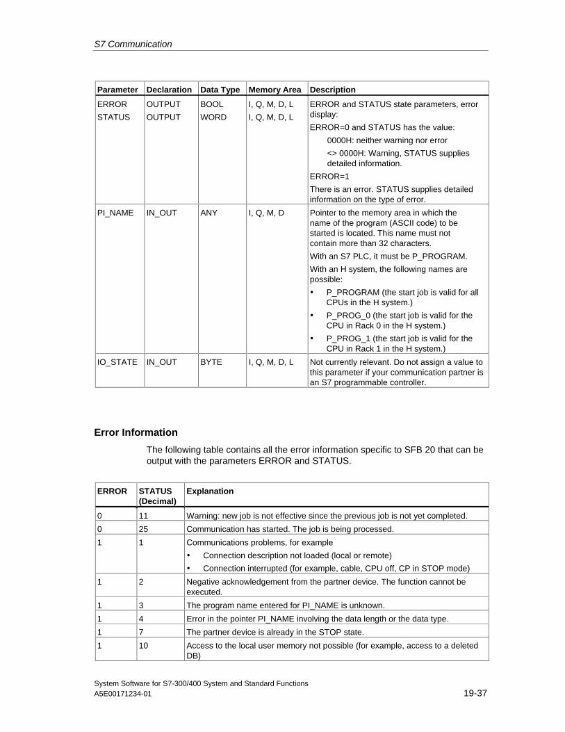
S7 Communication
System Software for S7-300/400 System and Standard FunctionsA5E00171234-01 19-37
Parameter Declaration Data Type Memory Area Description
ERROR
STATUS
OUTPUT
OUTPUT
BOOL
WORD
I, Q, M, D, L
I, Q, M, D, L
ERROR and STATUS state parameters, errordisplay:
ERROR=0 and STATUS has the value:
0000H: neither warning nor error
<> 0000H: Warning, STATUS suppliesdetailed information.
ERROR=1
There is an error. STATUS supplies detailedinformation on the type of error.
PI_NAME IN_OUT ANY I, Q, M, D Pointer to the memory area in which thename of the program (ASCII code) to bestarted is located. This name must notcontain more than 32 characters.
With an S7 PLC, it must be P_PROGRAM.
With an H system, the following names arepossible:
• P_PROGRAM (the start job is valid for allCPUs in the H system.)
• P_PROG_0 (the start job is valid for theCPU in Rack 0 in the H system.)
• P_PROG_1 (the start job is valid for theCPU in Rack 1 in the H system.)
IO_STATE IN_OUT BYTE I, Q, M, D, L Not currently relevant. Do not assign a value tothis parameter if your communication partner isan S7 programmable controller.
Error Information
The following table contains all the error information specific to SFB 20 that can beoutput with the parameters ERROR and STATUS.
ERROR STATUS(Decimal)
Explanation
0 11 Warning: new job is not effective since the previous job is not yet completed.
0 25 Communication has started. The job is being processed.
1 1 Communications problems, for example
• Connection description not loaded (local or remote)
• Connection interrupted (for example, cable, CPU off, CP in STOP mode)
1 2 Negative acknowledgement from the partner device. The function cannot beexecuted.
1 3 The program name entered for PI_NAME is unknown.
1 4 Error in the pointer PI_NAME involving the data length or the data type.
1 7 The partner device is already in the STOP state.
1 10 Access to the local user memory not possible (for example, access to a deletedDB)
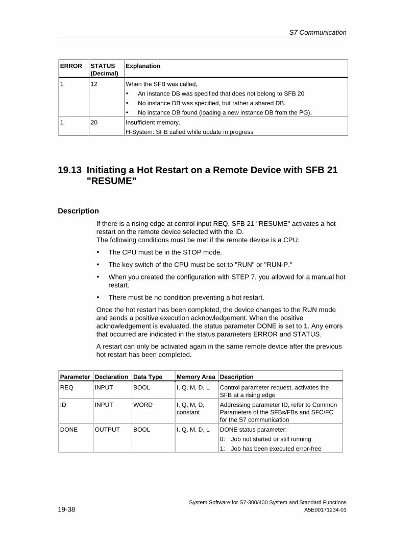
S7 Communication
System Software for S7-300/400 System and Standard Functions19-38 A5E00171234-01
ERROR STATUS(Decimal)
Explanation
1 12 When the SFB was called,
• An instance DB was specified that does not belong to SFB 20
• No instance DB was specified, but rather a shared DB.
• No instance DB found (loading a new instance DB from the PG).
1 20 Insufficient memory.
H-System: SFB called while update in progress
19.13 Initiating a Hot Restart on a Remote Device with SFB 21"RESUME"
Description
If there is a rising edge at control input REQ, SFB 21 "RESUME" activates a hotrestart on the remote device selected with the ID.The following conditions must be met if the remote device is a CPU:
• The CPU must be in the STOP mode.
• The key switch of the CPU must be set to "RUN" or "RUN-P."
• When you created the configuration with STEP 7, you allowed for a manual hotrestart.
• There must be no condition preventing a hot restart.
Once the hot restart has been completed, the device changes to the RUN modeand sends a positive execution acknowledgement. When the positiveacknowledgement is evaluated, the status parameter DONE is set to 1. Any errorsthat occurred are indicated in the status parameters ERROR and STATUS.
A restart can only be activated again in the same remote device after the previoushot restart has been completed.
Parameter Declaration Data Type Memory Area Description
REQ INPUT BOOL I, Q, M, D, L Control parameter request, activates theSFB at a rising edge
ID INPUT WORD I, Q, M, D,constant
Addressing parameter ID, refer to CommonParameters of the SFBs/FBs and SFC/FCfor the S7 communication
DONE OUTPUT BOOL I, Q, M, D, L DONE status parameter:
0: Job not started or still running
1: Job has been executed error-free
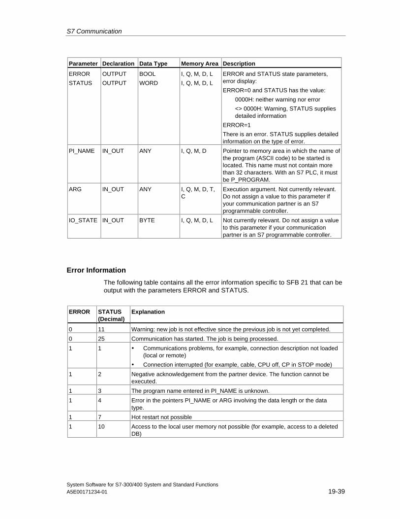
S7 Communication
System Software for S7-300/400 System and Standard FunctionsA5E00171234-01 19-39
Parameter Declaration Data Type Memory Area Description
ERROR
STATUS
OUTPUT
OUTPUT
BOOL
WORD
I, Q, M, D, L
I, Q, M, D, L
ERROR and STATUS state parameters,error display:
ERROR=0 and STATUS has the value:
0000H: neither warning nor error
<> 0000H: Warning, STATUS suppliesdetailed information
ERROR=1
There is an error. STATUS supplies detailedinformation on the type of error.
PI_NAME IN_OUT ANY I, Q, M, D Pointer to memory area in which the name ofthe program (ASCII code) to be started islocated. This name must not contain morethan 32 characters. With an S7 PLC, it mustbe P_PROGRAM.
ARG IN_OUT ANY I, Q, M, D, T,C
Execution argument. Not currently relevant.Do not assign a value to this parameter ifyour communication partner is an S7programmable controller.
IO_STATE IN_OUT BYTE I, Q, M, D, L Not currently relevant. Do not assign a valueto this parameter if your communicationpartner is an S7 programmable controller.
Error Information
The following table contains all the error information specific to SFB 21 that can beoutput with the parameters ERROR and STATUS.
ERROR STATUS(Decimal)
Explanation
0 11 Warning: new job is not effective since the previous job is not yet completed.
0 25 Communication has started. The job is being processed.
1 1 • Communications problems, for example, connection description not loaded(local or remote)
• Connection interrupted (for example, cable, CPU off, CP in STOP mode)
1 2 Negative acknowledgement from the partner device. The function cannot beexecuted.
1 3 The program name entered in PI_NAME is unknown.
1 4 Error in the pointers PI_NAME or ARG involving the data length or the datatype.
1 7 Hot restart not possible
1 10 Access to the local user memory not possible (for example, access to a deletedDB)
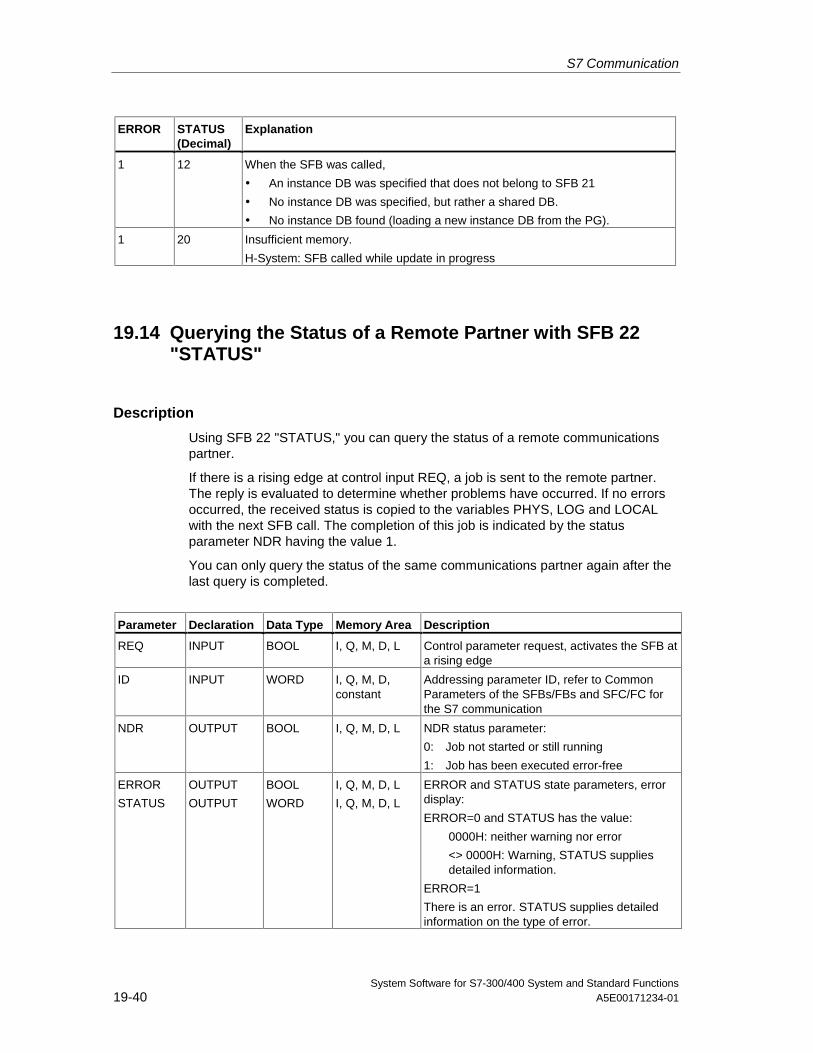
S7 Communication
System Software for S7-300/400 System and Standard Functions19-40 A5E00171234-01
ERROR STATUS(Decimal)
Explanation
1 12 When the SFB was called,
• An instance DB was specified that does not belong to SFB 21
• No instance DB was specified, but rather a shared DB.
• No instance DB found (loading a new instance DB from the PG).
1 20 Insufficient memory.
H-System: SFB called while update in progress
19.14 Querying the Status of a Remote Partner with SFB 22"STATUS"
Description
Using SFB 22 "STATUS," you can query the status of a remote communicationspartner.
If there is a rising edge at control input REQ, a job is sent to the remote partner.The reply is evaluated to determine whether problems have occurred. If no errorsoccurred, the received status is copied to the variables PHYS, LOG and LOCALwith the next SFB call. The completion of this job is indicated by the statusparameter NDR having the value 1.
You can only query the status of the same communications partner again after thelast query is completed.
Parameter Declaration Data Type Memory Area Description
REQ INPUT BOOL I, Q, M, D, L Control parameter request, activates the SFB ata rising edge
ID INPUT WORD I, Q, M, D,constant
Addressing parameter ID, refer to CommonParameters of the SFBs/FBs and SFC/FC forthe S7 communication
NDR OUTPUT BOOL I, Q, M, D, L NDR status parameter:
0: Job not started or still running
1: Job has been executed error-free
ERROR
STATUS
OUTPUT
OUTPUT
BOOL
WORD
I, Q, M, D, L
I, Q, M, D, L
ERROR and STATUS state parameters, errordisplay:
ERROR=0 and STATUS has the value:
0000H: neither warning nor error
<> 0000H: Warning, STATUS suppliesdetailed information.
ERROR=1
There is an error. STATUS supplies detailedinformation on the type of error.
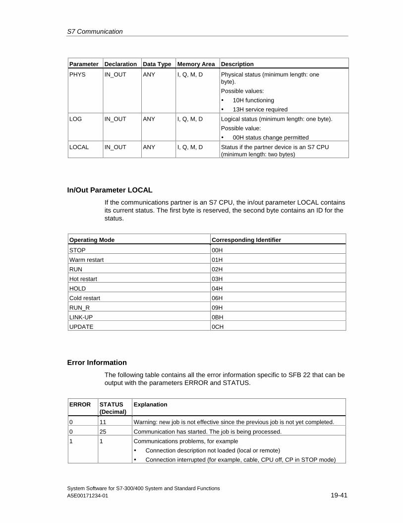
S7 Communication
System Software for S7-300/400 System and Standard FunctionsA5E00171234-01 19-41
Parameter Declaration Data Type Memory Area Description
PHYS IN_OUT ANY I, Q, M, D Physical status (minimum length: onebyte).
Possible values:
• 10H functioning
• 13H service required
LOG IN_OUT ANY I, Q, M, D Logical status (minimum length: one byte).
Possible value:
• 00H status change permitted
LOCAL IN_OUT ANY I, Q, M, D Status if the partner device is an S7 CPU(minimum length: two bytes)
In/Out Parameter LOCAL
If the communications partner is an S7 CPU, the in/out parameter LOCAL containsits current status. The first byte is reserved, the second byte contains an ID for thestatus.
Operating Mode Corresponding Identifier
STOP 00H
Warm restart 01H
RUN 02H
Hot restart 03H
HOLD 04H
Cold restart 06H
RUN_R 09H
LINK-UP 0BH
UPDATE 0CH
Error Information
The following table contains all the error information specific to SFB 22 that can beoutput with the parameters ERROR and STATUS.
ERROR STATUS(Decimal)
Explanation
0 11 Warning: new job is not effective since the previous job is not yet completed.
0 25 Communication has started. The job is being processed.
1 1 Communications problems, for example
• Connection description not loaded (local or remote)
• Connection interrupted (for example, cable, CPU off, CP in STOP mode)
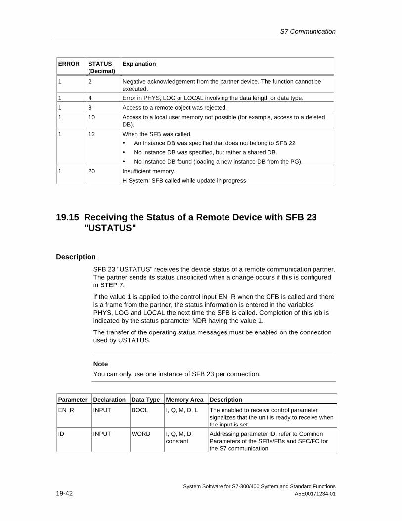
S7 Communication
System Software for S7-300/400 System and Standard Functions19-42 A5E00171234-01
ERROR STATUS(Decimal)
Explanation
1 2 Negative acknowledgement from the partner device. The function cannot beexecuted.
1 4 Error in PHYS, LOG or LOCAL involving the data length or data type.
1 8 Access to a remote object was rejected.
1 10 Access to a local user memory not possible (for example, access to a deletedDB).
1 12 When the SFB was called,
• An instance DB was specified that does not belong to SFB 22
• No instance DB was specified, but rather a shared DB.
• No instance DB found (loading a new instance DB from the PG).
1 20 Insufficient memory.
H-System: SFB called while update in progress
19.15 Receiving the Status of a Remote Device with SFB 23"USTATUS"
Description
SFB 23 "USTATUS" receives the device status of a remote communication partner.The partner sends its status unsolicited when a change occurs if this is configuredin STEP 7.
If the value 1 is applied to the control input EN_R when the CFB is called and thereis a frame from the partner, the status information is entered in the variablesPHYS, LOG and LOCAL the next time the SFB is called. Completion of this job isindicated by the status parameter NDR having the value 1.
The transfer of the operating status messages must be enabled on the connectionused by USTATUS.
Note
You can only use one instance of SFB 23 per connection.
Parameter Declaration Data Type Memory Area Description
EN_R INPUT BOOL I, Q, M, D, L The enabled to receive control parametersignalizes that the unit is ready to receive whenthe input is set.
ID INPUT WORD I, Q, M, D,constant
Addressing parameter ID, refer to CommonParameters of the SFBs/FBs and SFC/FC forthe S7 communication
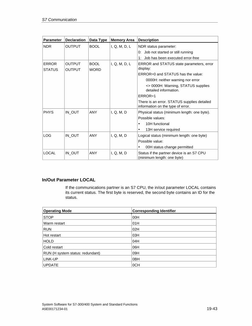
S7 Communication
System Software for S7-300/400 System and Standard FunctionsA5E00171234-01 19-43
Parameter Declaration Data Type Memory Area Description
NDR OUTPUT BOOL I, Q, M, D, L NDR status parameter:
0: Job not started or still running
1: Job has been executed error-free
ERROR
STATUS
OUTPUT
OUTPUT
BOOL
WORD
I, Q, M, D, L ERROR and STATUS state parameters, errordisplay:
ERROR=0 and STATUS has the value:
0000H: neither warning nor error
<> 0000H: Warning, STATUS suppliesdetailed information.
ERROR=1
There is an error. STATUS supplies detailedinformation on the type of error.
PHYS IN_OUT ANY I, Q, M, D Physical status (minimum length: one byte).
Possible values:
• 10H functional
• 13H service required
LOG IN_OUT ANY I, Q, M, D Logical status (minimum length: one byte)
Possible value:
• 00H status change permitted
LOCAL IN_OUT ANY I, Q, M, D Status if the partner device is an S7 CPU(minimum length: one byte)
In/Out Parameter LOCAL
If the communications partner is an S7 CPU, the in/out parameter LOCAL containsits current status. The first byte is reserved, the second byte contains an ID for thestatus.
Operating Mode Corresponding Identifier
STOP 00H
Warm restart 01H
RUN 02H
Hot restart 03H
HOLD 04H
Cold restart 06H
RUN (H system status: redundant) 09H
LINK-UP 0BH
UPDATE 0CH
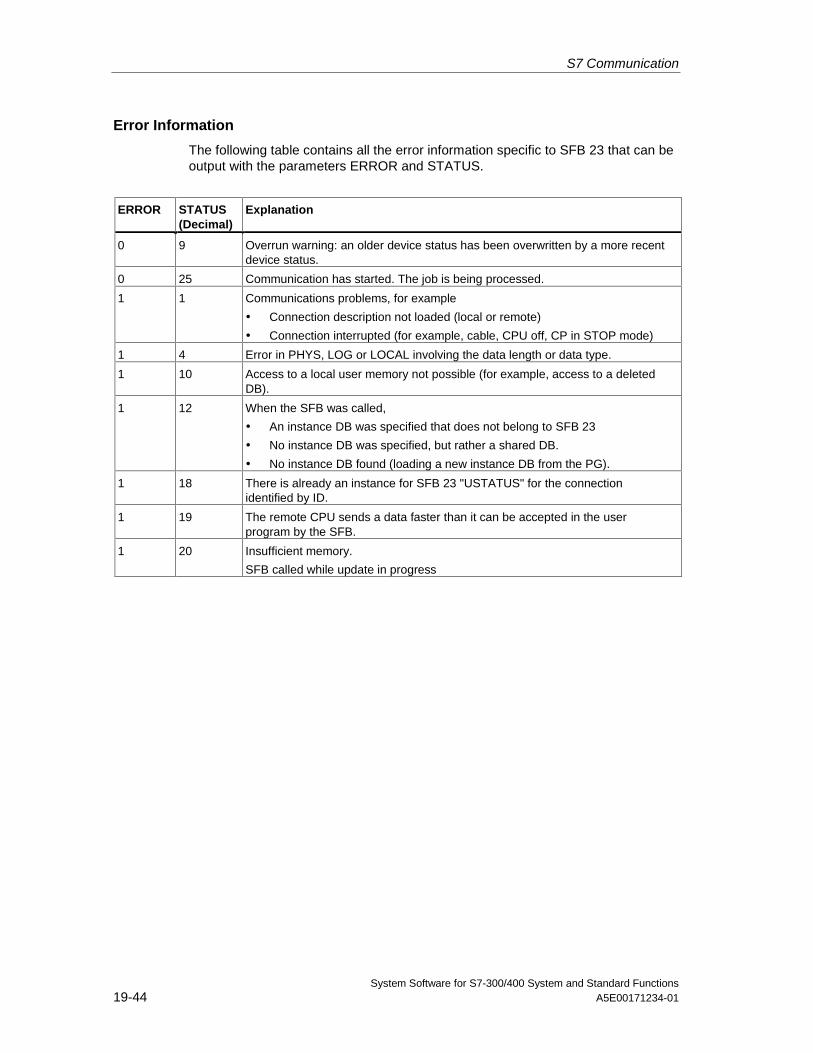
S7 Communication
System Software for S7-300/400 System and Standard Functions19-44 A5E00171234-01
Error Information
The following table contains all the error information specific to SFB 23 that can beoutput with the parameters ERROR and STATUS.
ERROR STATUS(Decimal)
Explanation
0 9 Overrun warning: an older device status has been overwritten by a more recentdevice status.
0 25 Communication has started. The job is being processed.
1 1 Communications problems, for example
• Connection description not loaded (local or remote)
• Connection interrupted (for example, cable, CPU off, CP in STOP mode)
1 4 Error in PHYS, LOG or LOCAL involving the data length or data type.
1 10 Access to a local user memory not possible (for example, access to a deletedDB).
1 12 When the SFB was called,
• An instance DB was specified that does not belong to SFB 23
• No instance DB was specified, but rather a shared DB.
• No instance DB found (loading a new instance DB from the PG).
1 18 There is already an instance for SFB 23 "USTATUS" for the connectionidentified by ID.
1 19 The remote CPU sends a data faster than it can be accepted in the userprogram by the SFB.
1 20 Insufficient memory.
SFB called while update in progress
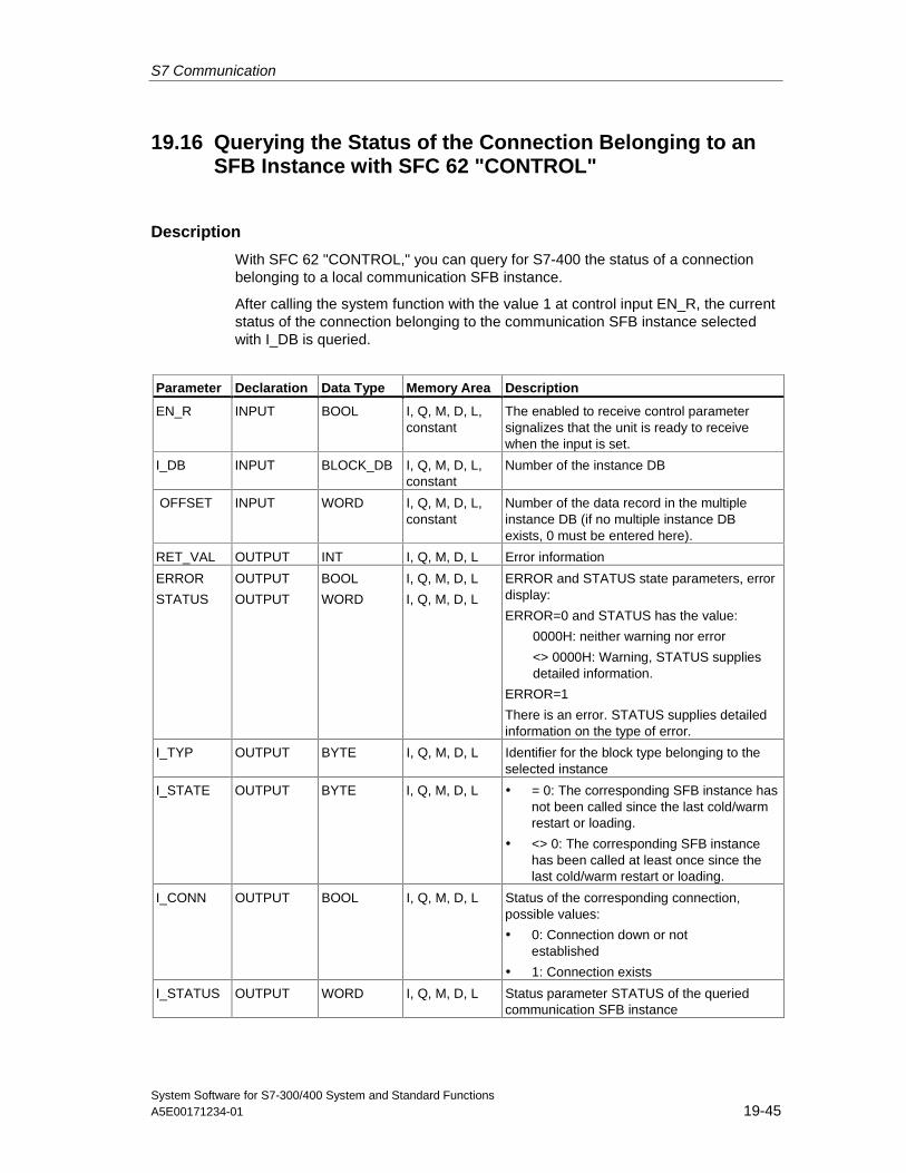
S7 Communication
System Software for S7-300/400 System and Standard FunctionsA5E00171234-01 19-45
19.16 Querying the Status of the Connection Belonging to anSFB Instance with SFC 62 "CONTROL"
Description
With SFC 62 "CONTROL," you can query for S7-400 the status of a connectionbelonging to a local communication SFB instance.
After calling the system function with the value 1 at control input EN_R, the currentstatus of the connection belonging to the communication SFB instance selectedwith I_DB is queried.
Parameter Declaration Data Type Memory Area Description
EN_R INPUT BOOL I, Q, M, D, L,constant
The enabled to receive control parametersignalizes that the unit is ready to receivewhen the input is set.
I_DB INPUT BLOCK_DB I, Q, M, D, L,constant
Number of the instance DB
OFFSET INPUT WORD I, Q, M, D, L,constant
Number of the data record in the multipleinstance DB (if no multiple instance DBexists, 0 must be entered here).
RET_VAL OUTPUT INT I, Q, M, D, L Error information
ERROR
STATUS
OUTPUT
OUTPUT
BOOL
WORD
I, Q, M, D, L
I, Q, M, D, L
ERROR and STATUS state parameters, errordisplay:
ERROR=0 and STATUS has the value:
0000H: neither warning nor error
<> 0000H: Warning, STATUS suppliesdetailed information.
ERROR=1
There is an error. STATUS supplies detailedinformation on the type of error.
I_TYP OUTPUT BYTE I, Q, M, D, L Identifier for the block type belonging to theselected instance
I_STATE OUTPUT BYTE I, Q, M, D, L • = 0: The corresponding SFB instance hasnot been called since the last cold/warmrestart or loading.
• <> 0: The corresponding SFB instancehas been called at least once since thelast cold/warm restart or loading.
I_CONN OUTPUT BOOL I, Q, M, D, L Status of the corresponding connection,possible values:
• 0: Connection down or notestablished
• 1: Connection exists
I_STATUS OUTPUT WORD I, Q, M, D, L Status parameter STATUS of the queriedcommunication SFB instance
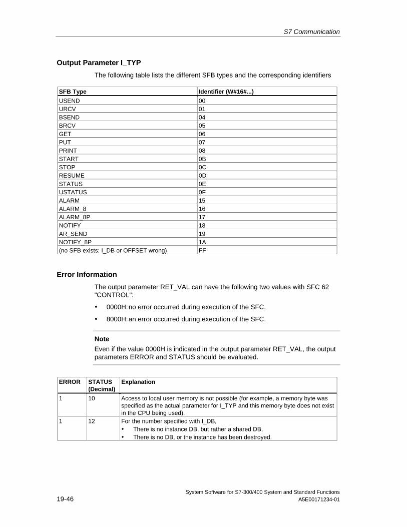
S7 Communication
System Software for S7-300/400 System and Standard Functions19-46 A5E00171234-01
Output Parameter I_TYP
The following table lists the different SFB types and the corresponding identifiers
SFB Type Identifier (W#16#...)
USEND 00URCV 01BSEND 04BRCV 05GET 06PUT 07PRINT 08START 0BSTOP 0CRESUME 0DSTATUS 0EUSTATUS 0FALARM 15ALARM_8 16ALARM_8P 17NOTIFY 18AR_SEND 19NOTIFY_8P 1A(no SFB exists; I_DB or OFFSET wrong) FF
Error Information
The output parameter RET_VAL can have the following two values with SFC 62"CONTROL":
• 0000H:no error occurred during execution of the SFC.
• 8000H:an error occurred during execution of the SFC.
Note
Even if the value 0000H is indicated in the output parameter RET_VAL, the outputparameters ERROR and STATUS should be evaluated.
ERROR STATUS(Decimal)
Explanation
1 10 Access to local user memory is not possible (for example, a memory byte wasspecified as the actual parameter for I_TYP and this memory byte does not existin the CPU being used).
1 12 For the number specified with I_DB,• There is no instance DB, but rather a shared DB,• There is no DB, or the instance has been destroyed.
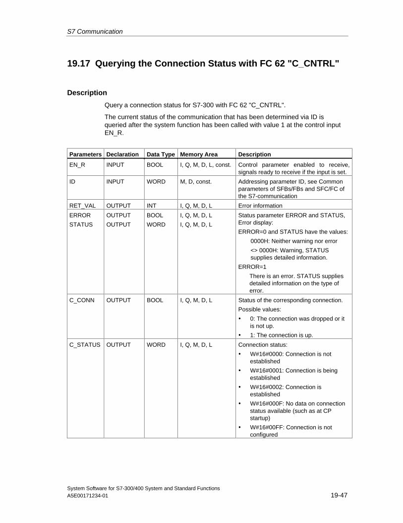
S7 Communication
System Software for S7-300/400 System and Standard FunctionsA5E00171234-01 19-47
19.17 Querying the Connection Status with FC 62 "C_CNTRL"
Description
Query a connection status for S7-300 with FC 62 "C_CNTRL".
The current status of the communication that has been determined via ID isqueried after the system function has been called with value 1 at the control inputEN_R.
Parameters Declaration Data Type Memory Area Description
EN_R INPUT BOOL I, Q, M, D, L, const. Control parameter enabled to receive,signals ready to receive if the input is set.
ID INPUT WORD M, D, const. Addressing parameter ID, see Commonparameters of SFBs/FBs and SFC/FC ofthe S7-communication
RET_VAL OUTPUT INT I, Q, M, D, L Error information
ERROR
STATUS
OUTPUT
OUTPUT
BOOL
WORD
I, Q, M, D, L
I, Q, M, D, L
Status parameter ERROR and STATUS,Error display:
ERROR=0 and STATUS have the values:
0000H: Neither warning nor error
<> 0000H: Warning, STATUSsupplies detailed information.
ERROR=1
There is an error. STATUS suppliesdetailed information on the type oferror.
C_CONN OUTPUT BOOL I, Q, M, D, L Status of the corresponding connection.
Possible values:
• 0: The connection was dropped or itis not up.
• 1: The connection is up.
C_STATUS OUTPUT WORD I, Q, M, D, L Connection status:
• W#16#0000: Connection is notestablished
• W#16#0001: Connection is beingestablished
• W#16#0002: Connection isestablished
• W#16#000F: No data on connectionstatus available (such as at CPstartup)
• W#16#00FF: Connection is notconfigured
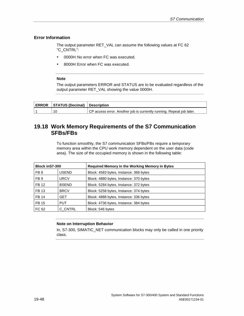
S7 Communication
System Software for S7-300/400 System and Standard Functions19-48 A5E00171234-01
Error Information
The output parameter RET_VAL can assume the following values at FC 62"C_CNTRL":
• 0000H:No error when FC was executed.
• 8000H:Error when FC was executed.
Note
The output parameters ERROR and STATUS are to be evaluated regardless of theoutput parameter RET_VAL showing the value 0000H.
ERROR STATUS (Decimal) Description
1 10 CP access error. Another job is currently running. Repeat job later.
19.18 Work Memory Requirements of the S7 CommunicationSFBs/FBs
To function smoothly, the S7 communication SFBs/FBs require a temporarymemory area within the CPU work memory dependent on the user data (codearea). The size of the occupied memory is shown in the following table:
Block inS7-300 Required Memory in the Working Memory in Bytes
FB 8 USEND Block: 4583 bytes, Instance: 368 bytes
FB 9 URCV Block: 4880 bytes, Instance: 370 bytes
FB 12 BSEND Block: 5284 bytes, Instance: 372 bytes
FB 13 BRCV Block: 5258 bytes, Instance: 374 bytes
FB 14 GET Block: 4888 bytes, Instance: 336 bytes
FB 15 PUT Block: 4736 bytes, Instance: 384 bytes
FC 62 C_CNTRL Block: 546 bytes
Note on Interruption Behavior
In, S7-300, SIMATIC_NET communication blocks may only be called in one priorityclass.
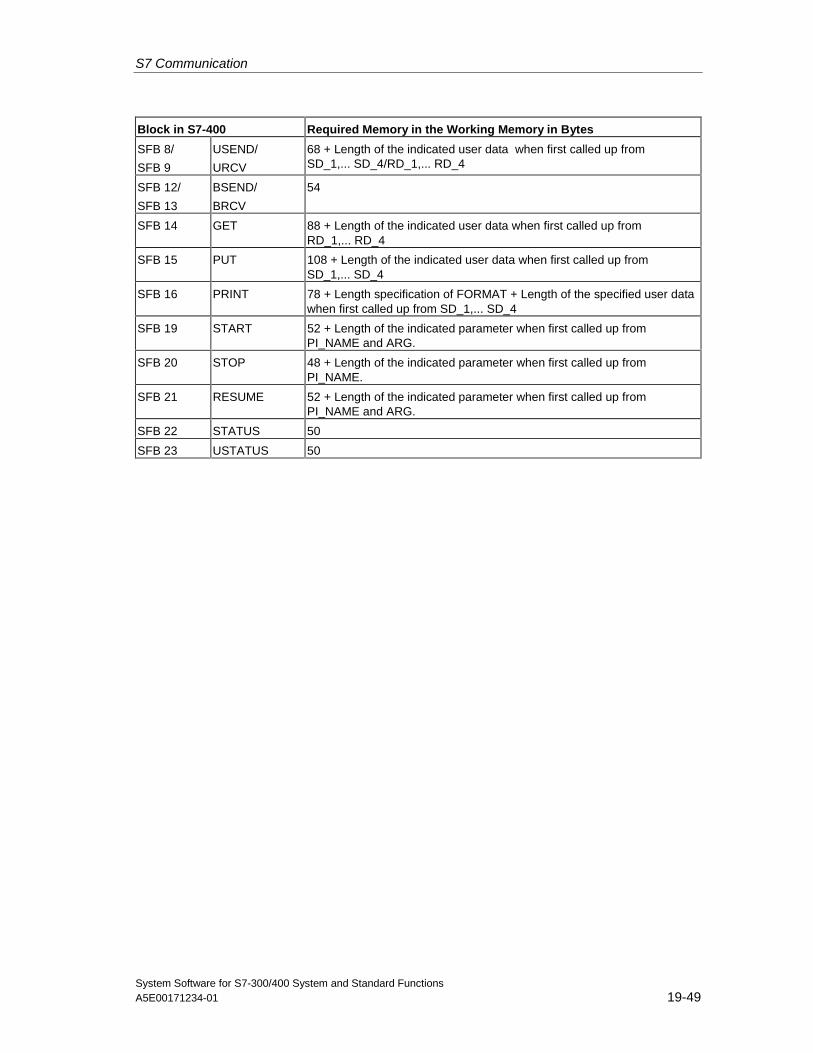
S7 Communication
System Software for S7-300/400 System and Standard FunctionsA5E00171234-01 19-49
Block in S7-400 Required Memory in the Working Memory in Bytes
SFB 8/
SFB 9
USEND/
URCV
68 + Length of the indicated user data when first called up fromSD_1,... SD_4/RD_1,... RD_4
SFB 12/
SFB 13
BSEND/
BRCV
54
SFB 14 GET 88 + Length of the indicated user data when first called up fromRD_1,... RD_4
SFB 15 PUT 108 + Length of the indicated user data when first called up fromSD_1,... SD_4
SFB 16 PRINT 78 + Length specification of FORMAT + Length of the specified user datawhen first called up from SD_1,... SD_4
SFB 19 START 52 + Length of the indicated parameter when first called up fromPI_NAME and ARG.
SFB 20 STOP 48 + Length of the indicated parameter when first called up fromPI_NAME.
SFB 21 RESUME 52 + Length of the indicated parameter when first called up fromPI_NAME and ARG.
SFB 22 STATUS 50
SFB 23 USTATUS 50

S7 Communication
System Software for S7-300/400 System and Standard Functions19-50 A5E00171234-01
System Software for S7-300/400 System and Standard FunctionsA5E00171234-01 20-1
20 Communication SFCs for Non-Configured S7Connections
20.1 Common Parameters of the Communication SFCs
Input Parameter REQ
The input parameter REQ (request to activate) is a level-triggered controlparameter. It is used to trigger the job (the data transfer or the connection abort):
• If you call the SFC for a job that is not currently active, you trigger the job withREQ=1. If there is no connection to the communication partner when thecommunication SFC is called the first time, the connection is establishedbefore data transfer begins.
• If you trigger a job and it is not yet completed when you call the SFC again forthe same job, REQ is not evaluated by the SFC.
Input Parameter REQ_ID (only SFC 65 and SFC 66)
The input parameter REQ_ID is used to identify your send data. It is passed by theoperating system of the sending CPU to the SFC 66 "X_RCV" of the CPU of thecommunication partner.
You require the REQ_ID parameter on the receiving end
• If you call several SFCs 65 "X_SEND" with different parameters REQ_ID onone send CPU and transfer the data to a communication partner.
• If you use SFC 65 "X_SEND" to send data to one communication partner fromseveral send CPUs.
By evaluating REQ_ID you can save the received data in different memory areas.
Output Parameters RET_VAL and BUSY
The communication SFCs are executed asynchronously, this means that theexecution of a job extends over more than one SFC call. The output parametersRET_VAL and BUSY indicate the status of the job. See also Meaning of theParameters REQ, RET_VAL and BUSY with Asynchronous SFCs
Communication SFCs for Non-Configured S7 Connections
System Software for S7-300/400 System and Standard Functions20-2 A5E00171234-01
Input Parameter CONT
The input parameter CONT (continue) is a control parameter. Using this parameter,you decide whether or not a connection to the communication partner remainsestablished after the job is completed.
• If you select CONT=0 at the first call, the connection is terminated again afterthe data transfer is completed. The connection is then available again for dataexchange with a new communication partner.
This method ensures that connection resources are only occupied when theyare actually in use.
• If you select CONT=1 at the first call, the connection remains established oncompletion of the data transfer.
This method is, for example, useful when you exchange data cyclicallybetween two stations.
Note
A connection established with CONT=1 can be terminated explicitly with SFC 69"X_ABORT" or with SFC 74 "I_ABORT."
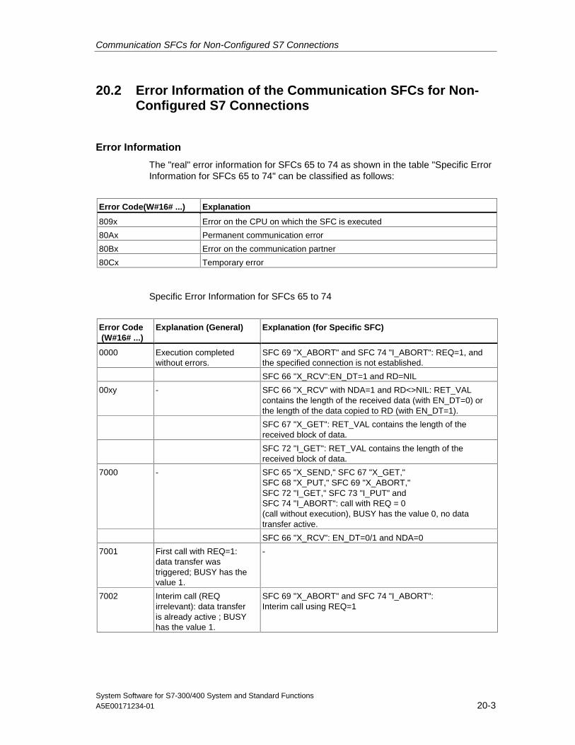
Communication SFCs for Non-Configured S7 Connections
System Software for S7-300/400 System and Standard FunctionsA5E00171234-01 20-3
20.2 Error Information of the Communication SFCs for Non-Configured S7 Connections
Error Information
The "real" error information for SFCs 65 to 74 as shown in the table "Specific ErrorInformation for SFCs 65 to 74" can be classified as follows:
Error Code(W#16# ...) Explanation
809x Error on the CPU on which the SFC is executed
80Ax Permanent communication error
80Bx Error on the communication partner
80Cx Temporary error
Specific Error Information for SFCs 65 to 74
Error Code (W#16# ...)
Explanation (General) Explanation (for Specific SFC)
0000 Execution completedwithout errors.
SFC 69 "X_ABORT" and SFC 74 "I_ABORT": REQ=1, andthe specified connection is not established.
SFC 66 "X_RCV":EN_DT=1 and RD=NIL
00xy - SFC 66 "X_RCV" with NDA=1 and RD<>NIL: RET_VALcontains the length of the received data (with EN_DT=0) orthe length of the data copied to RD (with EN_DT=1).
SFC 67 "X_GET": RET_VAL contains the length of thereceived block of data.
SFC 72 "I_GET": RET_VAL contains the length of thereceived block of data.
7000 - SFC 65 "X_SEND," SFC 67 "X_GET,"SFC 68 "X_PUT," SFC 69 "X_ABORT,"SFC 72 "I_GET," SFC 73 "I_PUT" andSFC 74 "I_ABORT": call with REQ = 0(call without execution), BUSY has the value 0, no datatransfer active.
SFC 66 "X_RCV": EN_DT=0/1 and NDA=0
7001 First call with REQ=1:data transfer wastriggered; BUSY has thevalue 1.
-
7002 Interim call (REQirrelevant): data transferis already active ; BUSYhas the value 1.
SFC 69 "X_ABORT" and SFC 74 "I_ABORT":Interim call using REQ=1
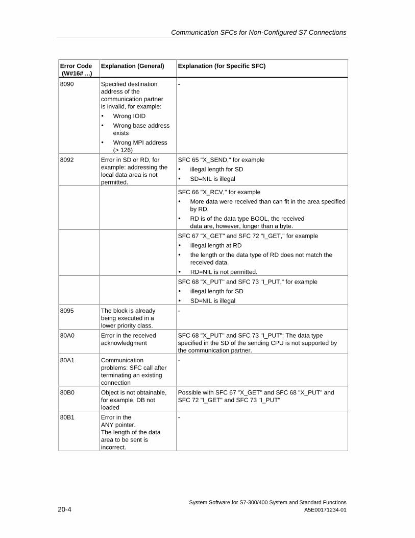
Communication SFCs for Non-Configured S7 Connections
System Software for S7-300/400 System and Standard Functions20-4 A5E00171234-01
Error Code (W#16# ...)
Explanation (General) Explanation (for Specific SFC)
8090 Specified destinationaddress of thecommunication partneris invalid, for example:
• Wrong IOID
• Wrong base addressexists
• Wrong MPI address(> 126)
-
8092 Error in SD or RD, forexample: addressing thelocal data area is notpermitted.
SFC 65 "X_SEND," for example
• illegal length for SD
• SD=NIL is illegal
SFC 66 "X_RCV," for example
• More data were received than can fit in the area specifiedby RD.
• RD is of the data type BOOL, the receiveddata are, however, longer than a byte.
SFC 67 "X_GET" and SFC 72 "I_GET," for example
• illegal length at RD
• the length or the data type of RD does not match thereceived data.
• RD=NIL is not permitted.
SFC 68 "X_PUT" and SFC 73 "I_PUT," for example
• illegal length for SD
• SD=NIL is illegal
8095 The block is alreadybeing executed in alower priority class.
-
80A0 Error in the receivedacknowledgment
SFC 68 "X_PUT" and SFC 73 "I_PUT": The data typespecified in the SD of the sending CPU is not supported bythe communication partner.
80A1 Communicationproblems: SFC call afterterminating an existingconnection
-
80B0 Object is not obtainable,for example, DB notloaded
Possible with SFC 67 "X_GET" and SFC 68 "X_PUT" andSFC 72 "I_GET" and SFC 73 "I_PUT"
80B1 Error in theANY pointer.The length of the dataarea to be sent isincorrect.
-
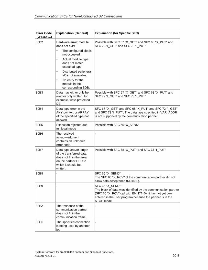
Communication SFCs for Non-Configured S7 Connections
System Software for S7-300/400 System and Standard FunctionsA5E00171234-01 20-5
Error Code (W#16# ...)
Explanation (General) Explanation (for Specific SFC)
80B2 Hardware error: moduledoes not exist
• The configured slot isnot occupied.
• Actual module typedoes not matchexpected type
• Distributed peripheralI/Os not available.
• No entry for themodule in thecorresponding SDB.
Possible with SFC 67 "X_GET" and SFC 68 "X_PUT" andSFC 72 "I_GET" and SFC 73 "I_PUT"
80B3 Data may either only beread or only written, forexample, write-protectedDB
Possible with SFC 67 "X_GET" and SFC 68 "X_PUT" andSFC 72 "I_GET" and SFC 73 "I_PUT"
80B4 Data type error in theANY pointer, or ARRAYof the specified type notallowed.
SFC 67 "X_GET" and SFC 68 "X_PUT" and SFC 72 "I_GET"and SFC 73 "I_PUT": The data type specified in VAR_ADDRis not supported by the communication partner.
80B5 Execution rejected dueto illegal mode
Possible with SFC 65 "X_SEND"
80B6 The receivedacknowledgmentcontains an unknownerror code.
-
80B7 Data type and/or lengthof the transferred datadoes not fit in the areaon the partner CPU towhich it should bewritten.
Possible with SFC 68 "X_PUT" and SFC 73 "I_PUT"
80B8 - SFC 65 "X_SEND":The SFC 66 "X_RCV" of the communication partner did notallow data acceptance (RD=NIL).
80B9 - SFC 65 "X_SEND":The block of data was identified by the communication partner(SFC 66 "X_RCV" call with EN_DT=0), it has not yet beenentered in the user program because the partner is in theSTOP mode.
80BA The response of thecommunication partnerdoes not fit in thecommunication frame.
-
80C0 The specified connectionis being used by anotherjob.
-
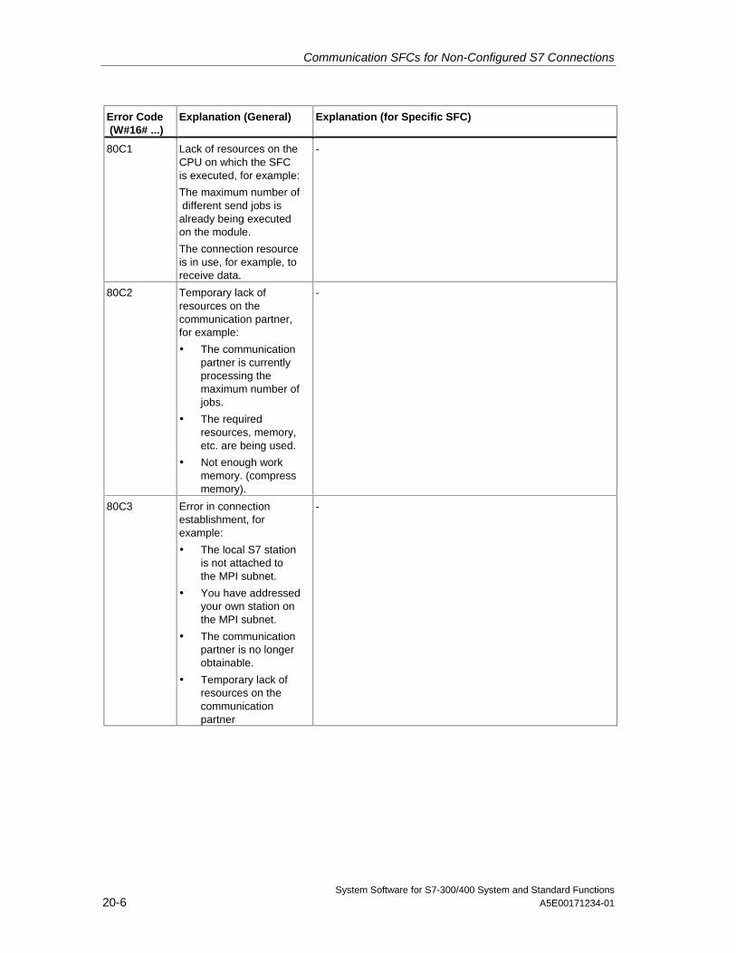
Communication SFCs for Non-Configured S7 Connections
System Software for S7-300/400 System and Standard Functions20-6 A5E00171234-01
Error Code (W#16# ...)
Explanation (General) Explanation (for Specific SFC)
80C1 Lack of resources on theCPU on which the SFCis executed, for example:
The maximum number of different send jobs isalready being executedon the module.
The connection resourceis in use, for example, toreceive data.
-
80C2 Temporary lack ofresources on thecommunication partner,for example:
• The communicationpartner is currentlyprocessing themaximum number ofjobs.
• The requiredresources, memory,etc. are being used.
• Not enough workmemory. (compressmemory).
-
80C3 Error in connectionestablishment, forexample:
• The local S7 stationis not attached tothe MPI subnet.
• You have addressedyour own station onthe MPI subnet.
• The communicationpartner is no longerobtainable.
• Temporary lack ofresources on thecommunicationpartner
-
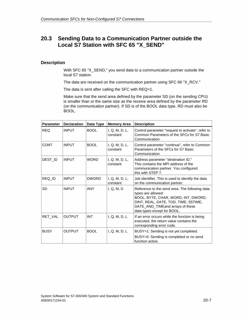
Communication SFCs for Non-Configured S7 Connections
System Software for S7-300/400 System and Standard FunctionsA5E00171234-01 20-7
20.3 Sending Data to a Communication Partner outside theLocal S7 Station with SFC 65 "X_SEND"
Description
With SFC 65 "X_SEND," you send data to a communication partner outside thelocal S7 station.
The data are received on the communication partner using SFC 66 "X_RCV."
The data is sent after calling the SFC with REQ=1.
Make sure that the send area defined by the parameter SD (on the sending CPU)is smaller than or the same size as the receive area defined by the parameter RD(on the communication partner). If SD is of the BOOL data type, RD must also beBOOL.
Parameter Declaration Data Type Memory Area Description
REQ INPUT BOOL I, Q, M, D, L,constant
Control parameter "request to activate", refer toCommon Parameters of the SFCs for S7 BasicCommunication
CONT INPUT BOOL I, Q, M, D, L,constant
Control parameter "continue", refer to CommonParameters of the SFCs for S7 BasicCommunication
DEST_ID INPUT WORD I, Q, M, D, L,constant
Address parameter "destination ID."This contains the MPI address of thecommunication partner. You configuredthis with STEP 7.
REQ_ID INPUT DWORD I, Q, M, D, L,constant
Job identifier. This is used to identify the dataon the communication partner.
SD INPUT ANY I, Q, M, D Reference to the send area. The following datatypes are allowed:BOOL, BYTE, CHAR, WORD, INT, DWORD,DINT, REAL, DATE, TOD, TIME, S5TIME,DATE_AND_TIMEand arrays of thesedata types except for BOOL.
RET_VAL OUTPUT INT I, Q, M, D, L If an error occurs while the function is beingexecuted, the return value contains thecorresponding error code.
BUSY OUTPUT BOOL I, Q, M, D, L BUSY=1: Sending is not yet completed.
BUSY=0: Sending is completed or no sendfunction active.
Communication SFCs for Non-Configured S7 Connections
System Software for S7-300/400 System and Standard Functions20-8 A5E00171234-01
Data Consistency
The data are sent in a consistent state.
Error Information
See Error Information of the Communication SFCs for Non-Configured S7Connections
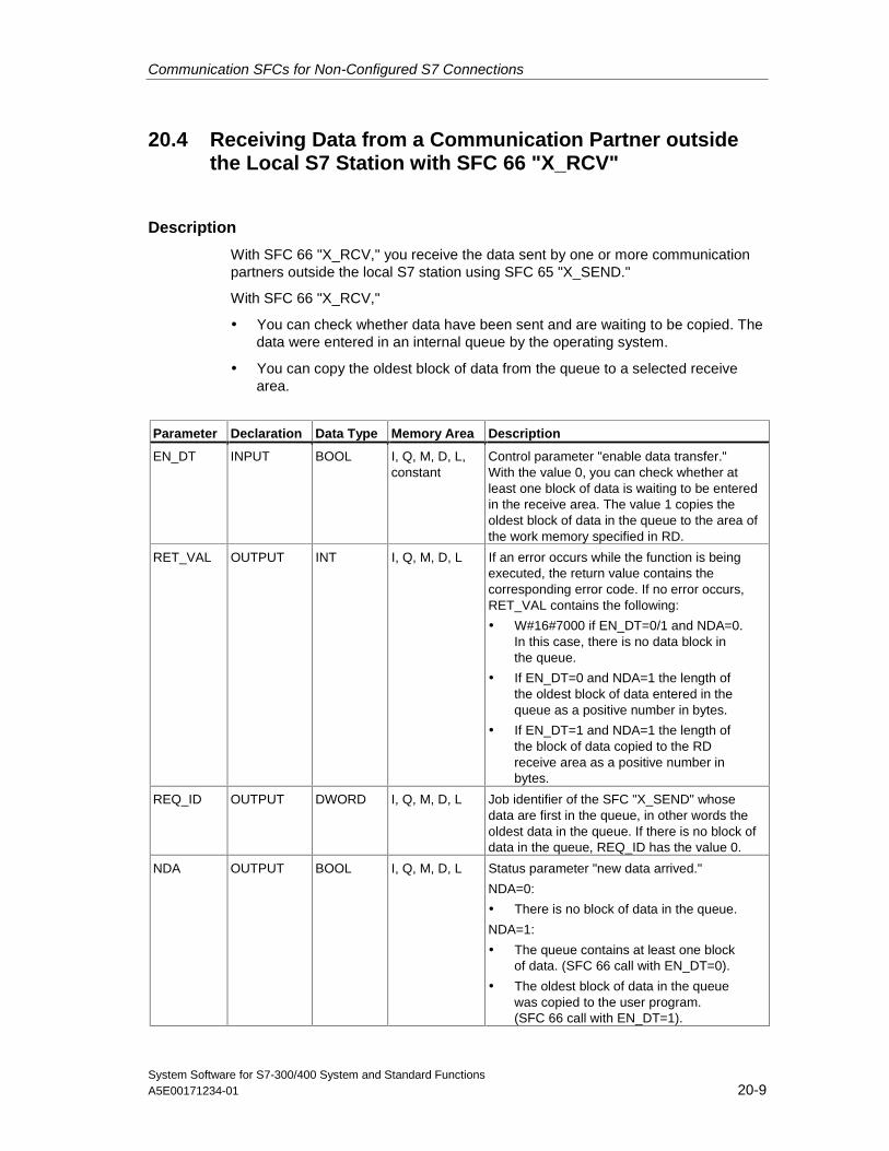
Communication SFCs for Non-Configured S7 Connections
System Software for S7-300/400 System and Standard FunctionsA5E00171234-01 20-9
20.4 Receiving Data from a Communication Partner outsidethe Local S7 Station with SFC 66 "X_RCV"
Description
With SFC 66 "X_RCV," you receive the data sent by one or more communicationpartners outside the local S7 station using SFC 65 "X_SEND."
With SFC 66 "X_RCV,"
• You can check whether data have been sent and are waiting to be copied. Thedata were entered in an internal queue by the operating system.
• You can copy the oldest block of data from the queue to a selected receivearea.
Parameter Declaration Data Type Memory Area Description
EN_DT INPUT BOOL I, Q, M, D, L,constant
Control parameter "enable data transfer."With the value 0, you can check whether atleast one block of data is waiting to be enteredin the receive area. The value 1 copies theoldest block of data in the queue to the area ofthe work memory specified in RD.
RET_VAL OUTPUT INT I, Q, M, D, L If an error occurs while the function is beingexecuted, the return value contains thecorresponding error code. If no error occurs,RET_VAL contains the following:
• W#16#7000 if EN_DT=0/1 and NDA=0.In this case, there is no data block inthe queue.
• If EN_DT=0 and NDA=1 the length ofthe oldest block of data entered in thequeue as a positive number in bytes.
• If EN_DT=1 and NDA=1 the length ofthe block of data copied to the RDreceive area as a positive number inbytes.
REQ_ID OUTPUT DWORD I, Q, M, D, L Job identifier of the SFC "X_SEND" whosedata are first in the queue, in other words theoldest data in the queue. If there is no block ofdata in the queue, REQ_ID has the value 0.
NDA OUTPUT BOOL I, Q, M, D, L Status parameter "new data arrived."
NDA=0:
• There is no block of data in the queue.
NDA=1:
• The queue contains at least one blockof data. (SFC 66 call with EN_DT=0).
• The oldest block of data in the queuewas copied to the user program.(SFC 66 call with EN_DT=1).
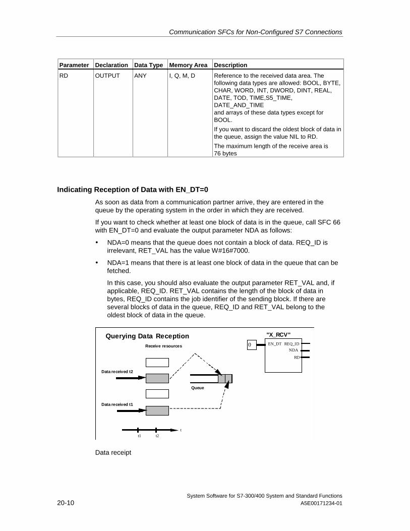
Communication SFCs for Non-Configured S7 Connections
System Software for S7-300/400 System and Standard Functions20-10 A5E00171234-01
Parameter Declaration Data Type Memory Area Description
RD OUTPUT ANY I, Q, M, D Reference to the received data area. Thefollowing data types are allowed: BOOL, BYTE,CHAR, WORD, INT, DWORD, DINT, REAL,DATE, TOD, TIME,S5_TIME,DATE_AND_TIMEand arrays of these data types except forBOOL.
If you want to discard the oldest block of data inthe queue, assign the value NIL to RD.
The maximum length of the receive area is76 bytes
Indicating Reception of Data with EN_DT=0
As soon as data from a communication partner arrive, they are entered in thequeue by the operating system in the order in which they are received.
If you want to check whether at least one block of data is in the queue, call SFC 66with EN_DT=0 and evaluate the output parameter NDA as follows:
• NDA=0 means that the queue does not contain a block of data. REQ_ID isirrelevant, RET_VAL has the value W#16#7000.
• NDA=1 means that there is at least one block of data in the queue that can befetched.
In this case, you should also evaluate the output parameter RET_VAL and, ifapplicable, REQ_ID. RET_VAL contains the length of the block of data inbytes, REQ_ID contains the job identifier of the sending block. If there areseveral blocks of data in the queue, REQ_ID and RET_VAL belong to theoldest block of data in the queue.
Data received t2
Receive resources
Data received t1
t1 t2t
Queue
REQ_ID
RD
EN_DT
"X_RCV"
NDA0
Querying Data Reception
Data receipt
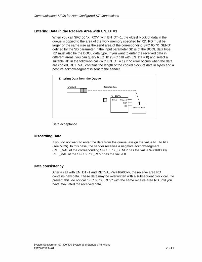
Communication SFCs for Non-Configured S7 Connections
System Software for S7-300/400 System and Standard FunctionsA5E00171234-01 20-11
Entering Data in the Receive Area with EN_DT=1
When you call SFC 66 "X_RCV" with EN_DT=1, the oldest block of data in thequeue is copied to the area of the work memory specified by RD. RD must belarger or the same size as the send area of the corresponding SFC 65 "X_SEND"defined by the SD parameter. If the input parameter SD is of the BOOL data type,RD must also be the BOOL data type. If you want to enter the received data indifferent areas, you can query REQ_ID (SFC call with EN_DT = 0) and select asuitable RD in the follow-on call (with EN_DT = 1).If no error occurs when the dataare copied, RET_VAL contains the length of the copied block of data in bytes and apositive acknowledgment is sent to the sender.
EN_DT REQ_ID
X_RCV
NDA
RD
Queue
Receive area
Transfer data
1
Entering Data from the Queue
Data acceptance
Discarding Data
If you do not want to enter the data from the queue, assign the value NIL to RD(see /232/). In this case, the sender receives a negative acknowledgment(RET_VAL of the corresponding SFC 65 "X_SEND" has the value W#1680B8).RET_VAL of the SFC 66 "X_RCV" has the value 0.
Data consistency
After a call with EN_DT=1 and RETVAL=W#16#00xy, the receive area RDcontains new data. These data may be overwritten with a subsequent block call. Toprevent this, do not call SFC 66 "X_RCV" with the same receive area RD until youhave evaluated the received data.
Communication SFCs for Non-Configured S7 Connections
System Software for S7-300/400 System and Standard Functions20-12 A5E00171234-01
Changing to the STOP Mode
If the CPU changes to the STOP mode
• all newly arriving jobs are acknowledged negatively.
• all jobs that have arrived and are in the queue are acknowledged negatively.
- If the STOP is followed by a warm or cold restart, the blocks of data are alldiscarded.
- If the STOP is followed by a restart, (not possible on an S7-300 and anS7-400H) the block of data belonging to the oldest job is entered in the userprogram, if the queue was queried before the change to the STOP mode(by calling SFC 66 "X_RCV" with EN_DT=0). Otherwise it is discarded.
All other blocks of data are discarded.
Connection Abort
If the connection is terminated a job belonging to the connection that is already inthe queue is discarded.
Exception: If this job is the oldest in the queue, and you have already detected itspresence by calling SFC 66 "X_RCV" with EN_DT=0, you can enter it in thereceive area with EN_DT=1.
Error Information
See Error Information of the Communication SFCs for Non-Configured S7Connections.
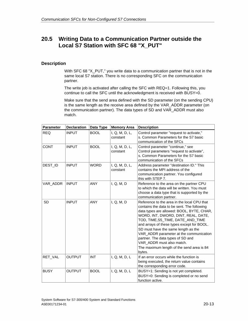
Communication SFCs for Non-Configured S7 Connections
System Software for S7-300/400 System and Standard FunctionsA5E00171234-01 20-13
20.5 Writing Data to a Communication Partner outside theLocal S7 Station with SFC 68 "X_PUT"
Description
With SFC 68 "X_PUT," you write data to a communication partner that is not in thesame local S7 station. There is no corresponding SFC on the communicationpartner.
The write job is activated after calling the SFC with REQ=1. Following this, youcontinue to call the SFC until the acknowledgment is received with BUSY=0.
Make sure that the send area defined with the SD parameter (on the sending CPU)is the same length as the receive area defined by the VAR_ADDR parameter (onthe communication partner). The data types of SD and VAR_ADDR must alsomatch.
Parameter Declaration Data Type Memory Area Description
REQ INPUT BOOL I, Q, M, D, L,constant
Control parameter "request to activate,"s. Common Parameters for the S7 basiccommunication of the SFCs
CONT INPUT BOOL I, Q, M, D, L,constant
Control parameter "continue," seeControl parameters "request to activate",s. Common Parameters for the S7 basiccommunication of the SFCs
DEST_ID INPUT WORD I, Q, M, D, L,constant
Address parameter "destination ID." Thiscontains the MPI address of thecommunication partner. You configuredthis with STEP 7.
VAR_ADDR INPUT ANY I, Q, M, D Reference to the area on the partner CPUto which the data will be written. You mustchoose a data type that is supported by thecommunication partner.
SD INPUT ANY I, Q, M, D Reference to the area in the local CPU thatcontains the data to be sent. The followingdata types are allowed: BOOL, BYTE, CHAR,WORD, INT, DWORD, DINT, REAL, DATE,TOD, TIME,S5_TIME, DATE_AND_TIMEand arrays of these types except for BOOL.SD must have the same length as theVAR_ADDR parameter at the communicationpartner. The data types of SD andVAR_ADDR must also match.The maximum length of the send area is 84bytes.
RET_VAL OUTPUT INT I, Q, M, D, L If an error occurs while the function isbeing executed, the return value containsthe corresponding error code.
BUSY OUTPUT BOOL I, Q, M, D, L BUSY=1: Sending is not yet completed.BUSY=0: Sending is completed or no sendfunction active.
Communication SFCs for Non-Configured S7 Connections
System Software for S7-300/400 System and Standard Functions20-14 A5E00171234-01
Changing to the STOP Mode
If the CPU changes to the STOP mode, the connection established by SFC 68"X_PUT" is terminated. Data can no longer be sent. If the send data have alreadybeen copied to the internal buffer when the CPU changes mode, the contents ofthe buffer are discarded.
Communication Partner Changes to the STOP Mode
If the CPU of the communication partner changes to the STOP mode, this does notaffect the data transfer with SFC 68 "X_PUT." The data can also be written with thepartner in the STOP mode.
Data Consistency
The data are sent in a consistent state.
Error Information
See Error Information of the Communication SFCs for Non-Configured S7Connections.
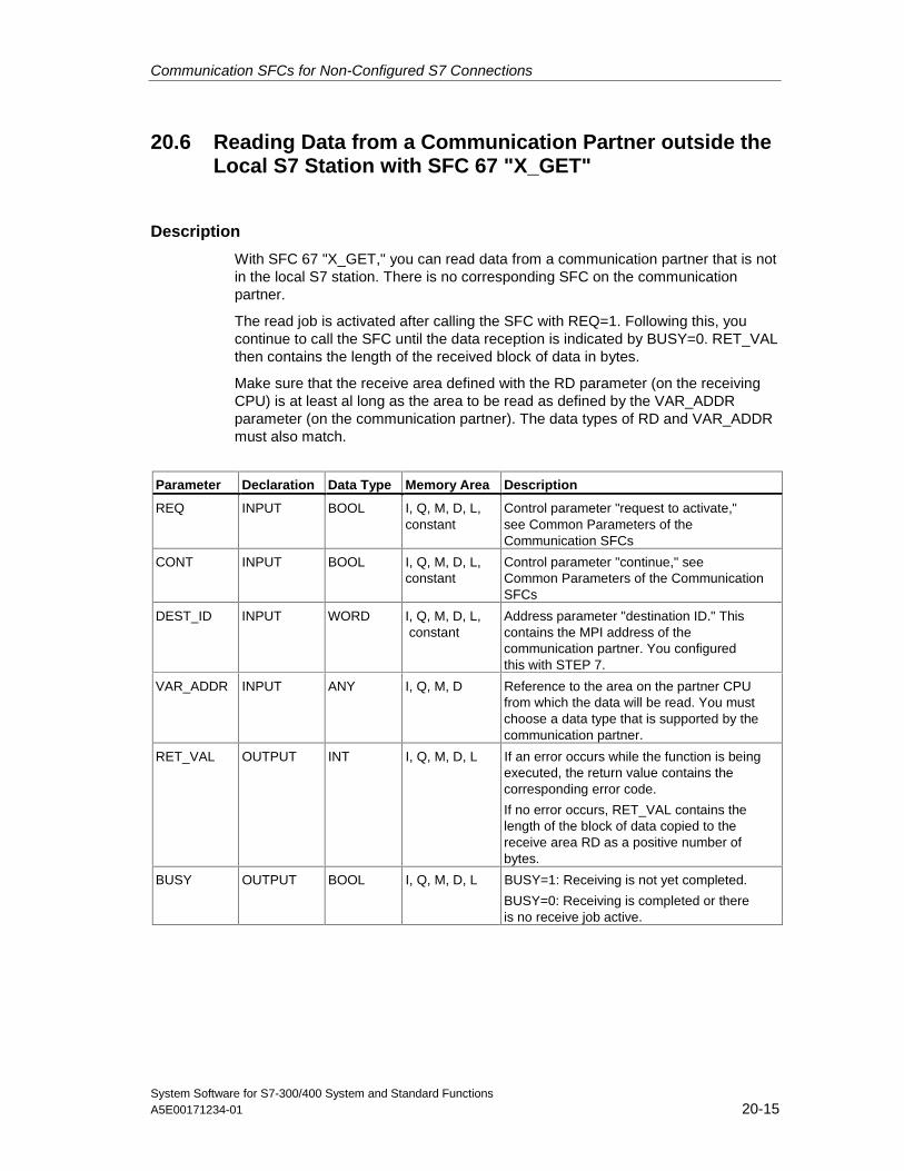
Communication SFCs for Non-Configured S7 Connections
System Software for S7-300/400 System and Standard FunctionsA5E00171234-01 20-15
20.6 Reading Data from a Communication Partner outside theLocal S7 Station with SFC 67 "X_GET"
Description
With SFC 67 "X_GET," you can read data from a communication partner that is notin the local S7 station. There is no corresponding SFC on the communicationpartner.
The read job is activated after calling the SFC with REQ=1. Following this, youcontinue to call the SFC until the data reception is indicated by BUSY=0. RET_VALthen contains the length of the received block of data in bytes.
Make sure that the receive area defined with the RD parameter (on the receivingCPU) is at least al long as the area to be read as defined by the VAR_ADDRparameter (on the communication partner). The data types of RD and VAR_ADDRmust also match.
Parameter Declaration Data Type Memory Area Description
REQ INPUT BOOL I, Q, M, D, L,constant
Control parameter "request to activate,"see Common Parameters of theCommunication SFCs
CONT INPUT BOOL I, Q, M, D, L,constant
Control parameter "continue," seeCommon Parameters of the CommunicationSFCs
DEST_ID INPUT WORD I, Q, M, D, L, constant
Address parameter "destination ID." Thiscontains the MPI address of thecommunication partner. You configuredthis with STEP 7.
VAR_ADDR INPUT ANY I, Q, M, D Reference to the area on the partner CPUfrom which the data will be read. You mustchoose a data type that is supported by thecommunication partner.
RET_VAL OUTPUT INT I, Q, M, D, L If an error occurs while the function is beingexecuted, the return value contains thecorresponding error code.
If no error occurs, RET_VAL contains thelength of the block of data copied to thereceive area RD as a positive number ofbytes.
BUSY OUTPUT BOOL I, Q, M, D, L BUSY=1: Receiving is not yet completed.
BUSY=0: Receiving is completed or thereis no receive job active.
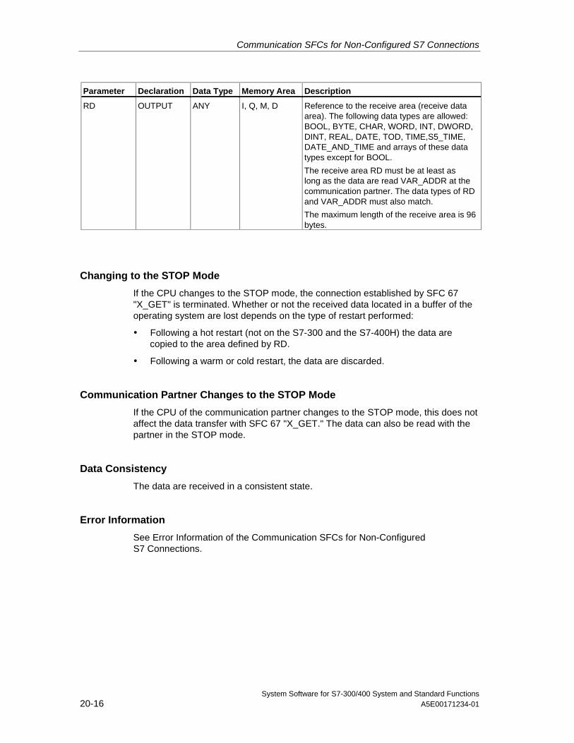
Communication SFCs for Non-Configured S7 Connections
System Software for S7-300/400 System and Standard Functions20-16 A5E00171234-01
Parameter Declaration Data Type Memory Area Description
RD OUTPUT ANY I, Q, M, D Reference to the receive area (receive dataarea). The following data types are allowed:BOOL, BYTE, CHAR, WORD, INT, DWORD,DINT, REAL, DATE, TOD, TIME,S5_TIME,DATE_AND_TIME and arrays of these datatypes except for BOOL.
The receive area RD must be at least aslong as the data are read VAR_ADDR at thecommunication partner. The data types of RDand VAR_ADDR must also match.
The maximum length of the receive area is 96bytes.
Changing to the STOP Mode
If the CPU changes to the STOP mode, the connection established by SFC 67"X_GET" is terminated. Whether or not the received data located in a buffer of theoperating system are lost depends on the type of restart performed:
• Following a hot restart (not on the S7-300 and the S7-400H) the data arecopied to the area defined by RD.
• Following a warm or cold restart, the data are discarded.
Communication Partner Changes to the STOP Mode
If the CPU of the communication partner changes to the STOP mode, this does notaffect the data transfer with SFC 67 "X_GET." The data can also be read with thepartner in the STOP mode.
Data Consistency
The data are received in a consistent state.
Error Information
See Error Information of the Communication SFCs for Non-ConfiguredS7 Connections.
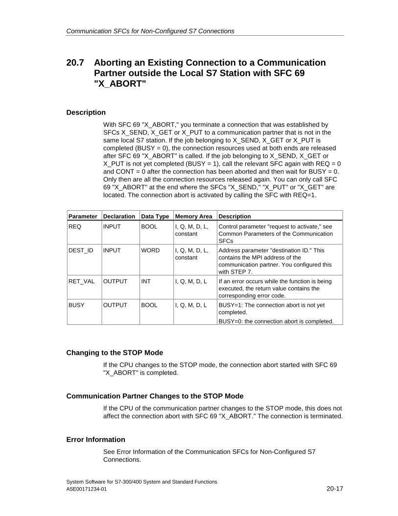
Communication SFCs for Non-Configured S7 Connections
System Software for S7-300/400 System and Standard FunctionsA5E00171234-01 20-17
20.7 Aborting an Existing Connection to a CommunicationPartner outside the Local S7 Station with SFC 69"X_ABORT"
Description
With SFC 69 "X_ABORT," you terminate a connection that was established bySFCs X_SEND, X_GET or X_PUT to a communication partner that is not in thesame local S7 station. If the job belonging to X_SEND, X_GET or X_PUT iscompleted (BUSY = 0), the connection resources used at both ends are releasedafter SFC 69 "X_ABORT" is called. If the job belonging to X_SEND, X_GET orX_PUT is not yet completed (BUSY = 1), call the relevant SFC again with REQ = 0and CONT = 0 after the connection has been aborted and then wait for BUSY = 0.Only then are all the connection resources released again. You can only call SFC69 "X_ABORT" at the end where the SFCs "X_SEND," "X_PUT" or "X_GET" arelocated. The connection abort is activated by calling the SFC with REQ=1.
Parameter Declaration Data Type Memory Area Description
REQ INPUT BOOL I, Q, M, D, L,constant
Control parameter "request to activate," seeCommon Parameters of the CommunicationSFCs
DEST_ID INPUT WORD I, Q, M, D, L,constant
Address parameter "destination ID." Thiscontains the MPI address of thecommunication partner. You configured thiswith STEP 7.
RET_VAL OUTPUT INT I, Q, M, D, L If an error occurs while the function is beingexecuted, the return value contains thecorresponding error code.
BUSY OUTPUT BOOL I, Q, M, D, L BUSY=1: The connection abort is not yetcompleted.
BUSY=0: the connection abort is completed.
Changing to the STOP Mode
If the CPU changes to the STOP mode, the connection abort started with SFC 69"X_ABORT" is completed.
Communication Partner Changes to the STOP Mode
If the CPU of the communication partner changes to the STOP mode, this does notaffect the connection abort with SFC 69 "X_ABORT." The connection is terminated.
Error Information
See Error Information of the Communication SFCs for Non-Configured S7Connections.
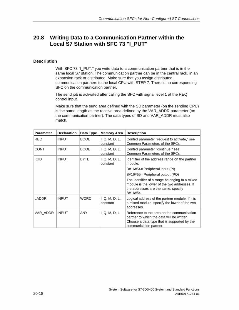
Communication SFCs for Non-Configured S7 Connections
System Software for S7-300/400 System and Standard Functions20-18 A5E00171234-01
20.8 Writing Data to a Communication Partner within theLocal S7 Station with SFC 73 "I_PUT"
Description
With SFC 73 "I_PUT," you write data to a communication partner that is in thesame local S7 station. The communication partner can be in the central rack, in anexpansion rack or distributed. Make sure that you assign distributedcommunication partners to the local CPU with STEP 7. There is no correspondingSFC on the communication partner.
The send job is activated after calling the SFC with signal level 1 at the REQcontrol input.
Make sure that the send area defined with the SD parameter (on the sending CPU)is the same length as the receive area defined by the VAR_ADDR parameter (onthe communication partner). The data types of SD and VAR_ADDR must alsomatch.
Parameter Declaration Data Type Memory Area Description
REQ INPUT BOOL I, Q, M, D, L,constant
Control parameter "request to activate," seeCommon Parameters of the SFCs.
CONT INPUT BOOL I, Q, M, D, L,constant
Control parameter "continue," seeCommon Parameters of the SFCs.
IOID INPUT BYTE I, Q, M, D, L,constant
Identifier of the address range on the partnermodule:
B#16#54= Peripheral input (PI)
B#16#55= Peripheral output (PQ)
The identifier of a range belonging to a mixedmodule is the lower of the two addresses. Ifthe addresses are the same, specifyB#16#54.
LADDR INPUT WORD I, Q, M, D, L,constant
Logical address of the partner module. If it isa mixed module, specify the lower of the twoaddresses.
VAR_ADDR INPUT ANY I, Q, M, D, L Reference to the area on the communicationpartner to which the data will be written.Choose a data type that is supported by thecommunication partner.
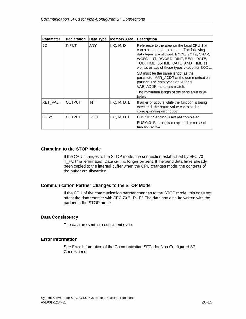
Communication SFCs for Non-Configured S7 Connections
System Software for S7-300/400 System and Standard FunctionsA5E00171234-01 20-19
Parameter Declaration Data Type Memory Area Description
SD INPUT ANY I, Q, M, D Reference to the area on the local CPU thatcontains the data to be sent. The followingdata types are allowed: BOOL, BYTE, CHAR,WORD, INT, DWORD, DINT, REAL, DATE,TOD, TIME, S5TIME, DATE_AND_TIME aswell as arrays of these types except for BOOL.
SD must be the same length as theparameter VAR_ADDR at the communicationpartner. The data types of SD andVAR_ADDR must also match.
The maximum length of the send area is 94bytes.
RET_VAL OUTPUT INT I, Q, M, D, L If an error occurs while the function is beingexecuted, the return value contains thecorresponding error code.
BUSY OUTPUT BOOL I, Q, M, D, L BUSY=1: Sending is not yet completed.
BUSY=0: Sending is completed or no sendfunction active.
Changing to the STOP Mode
If the CPU changes to the STOP mode, the connection established by SFC 73"I_PUT" is terminated. Data can no longer be sent. If the send data have alreadybeen copied to the internal buffer when the CPU changes mode, the contents ofthe buffer are discarded.
Communication Partner Changes to the STOP Mode
If the CPU of the communication partner changes to the STOP mode, this does notaffect the data transfer with SFC 73 "I_PUT." The data can also be written with thepartner in the STOP mode.
Data Consistency
The data are sent in a consistent state.
Error Information
See Error Information of the Communication SFCs for Non-Configured S7Connections.
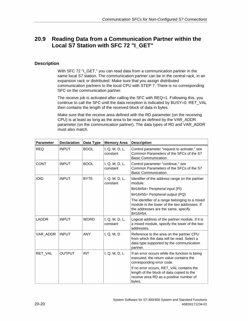
Communication SFCs for Non-Configured S7 Connections
System Software for S7-300/400 System and Standard Functions20-20 A5E00171234-01
20.9 Reading Data from a Communication Partner within theLocal S7 Station with SFC 72 "I_GET"
Description
With SFC 72 "I_GET," you can read data from a communication partner in thesame local S7 station. The communication partner can be in the central rack, in anexpansion rack or distributed. Make sure that you assign distributedcommunication partners to the local CPU with STEP 7. There is no correspondingSFC on the communication partner.
The receive job is activated after calling the SFC with REQ=1. Following this, youcontinue to call the SFC until the data reception is indicated by BUSY=0. RET_VALthen contains the length of the received block of data in bytes.
Make sure that the receive area defined with the RD parameter (on the receivingCPU) is at least as long as the area to be read as defined by the VAR_ADDRparameter (on the communication partner). The data types of RD and VAR_ADDRmust also match.
Parameter Declaration Data Type Memory Area Description
REQ INPUT BOOL I, Q, M, D, L,constant
Control parameter "request to activate," seeCommon Parameters of the SFCs of the S7Basic Communication.
CONT INPUT BOOL I, Q, M, D, L,constant
Control parameter "continue," seeCommon Parameters of the SFCs of the S7Basic Communication.
IOID INPUT BYTE I, Q, M, D, L,constant
Identifier of the address range on the partnermodule:
B#16#54= Peripheral input (PI)
B#16#55= Peripheral output (PQ)
The identifier of a range belonging to a mixedmodule is the lower of the two addresses. Ifthe addresses are the same, specifyB#16#54.
LADDR INPUT WORD I, Q, M, D, L,constant
Logical address of the partner module. If it isa mixed module, specify the lower of the twoaddresses.
VAR_ADDR INPUT ANY I, Q, M, D Reference to the area on the partner CPUfrom which the data will be read. Select adata type supported by the communicationpartner.
RET_VAL OUTPUT INT I, Q, M, D, L If an error occurs while the function is beingexecuted, the return value contains thecorresponding error code.
If no error occurs, RET_VAL contains thelength of the block of data copied to thereceive area RD as a positive number ofbytes.
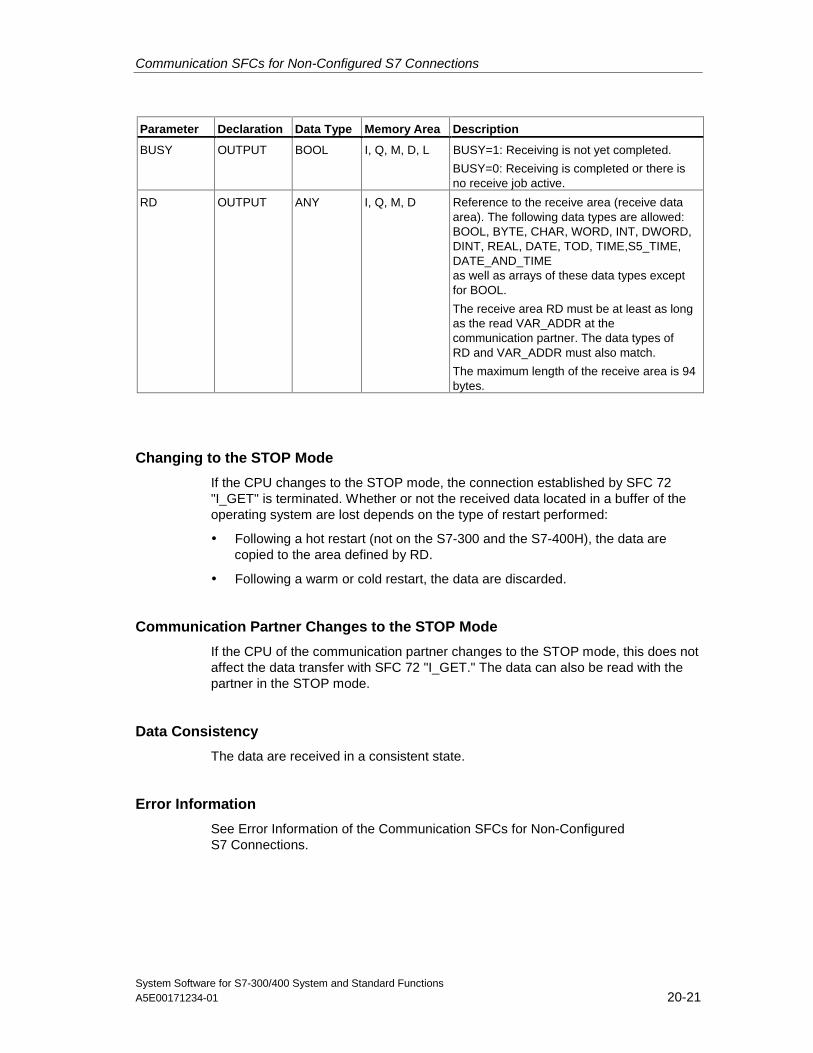
Communication SFCs for Non-Configured S7 Connections
System Software for S7-300/400 System and Standard FunctionsA5E00171234-01 20-21
Parameter Declaration Data Type Memory Area Description
BUSY OUTPUT BOOL I, Q, M, D, L BUSY=1: Receiving is not yet completed.
BUSY=0: Receiving is completed or there isno receive job active.
RD OUTPUT ANY I, Q, M, D Reference to the receive area (receive dataarea). The following data types are allowed:BOOL, BYTE, CHAR, WORD, INT, DWORD,DINT, REAL, DATE, TOD, TIME,S5_TIME,DATE_AND_TIMEas well as arrays of these data types exceptfor BOOL.
The receive area RD must be at least as longas the read VAR_ADDR at thecommunication partner. The data types ofRD and VAR_ADDR must also match.
The maximum length of the receive area is 94bytes.
Changing to the STOP Mode
If the CPU changes to the STOP mode, the connection established by SFC 72"I_GET" is terminated. Whether or not the received data located in a buffer of theoperating system are lost depends on the type of restart performed:
• Following a hot restart (not on the S7-300 and the S7-400H), the data arecopied to the area defined by RD.
• Following a warm or cold restart, the data are discarded.
Communication Partner Changes to the STOP Mode
If the CPU of the communication partner changes to the STOP mode, this does notaffect the data transfer with SFC 72 "I_GET." The data can also be read with thepartner in the STOP mode.
Data Consistency
The data are received in a consistent state.
Error Information
See Error Information of the Communication SFCs for Non-ConfiguredS7 Connections.
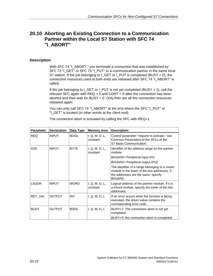
Communication SFCs for Non-Configured S7 Connections
System Software for S7-300/400 System and Standard Functions20-22 A5E00171234-01
20.10 Aborting an Existing Connection to a CommunicationPartner within the Local S7 Station with SFC 74"I_ABORT"
Description
With SFC 74 "I_ABORT," you terminate a connection that was established bySFC 72 "I_GET" or SFC 73 "I_PUT" to a communication partner in the same localS7 station. If the job belonging to I_GET or I_PUT is completed (BUSY = 0), theconnection resources used at both ends are released after SFC 74 "I_ABORT" iscalled.
If the job belonging to I_GET or I_PUT is not yet completed (BUSY = 1), call therelevant SFC again with REQ = 0 and CONT = 0 after the connection has beenaborted and then wait for BUSY = 0. Only then are all the connection resourcesreleased again.
You can only call SFC 74 "I_ABORT" at the end where the SFC "I_PUT" or"I_GET" is located (in other words at the client end).
The connection abort is activated by calling the SFC with REQ=1.
Parameter Declaration Data Type Memory Area Description
REQ INPUT BOOL I, Q, M, D, L,constant
Control parameter "request to activate," seeCommon Parameters of the SFCs of theS7 Basic Communication.
IOID INPUT BYTE I, Q, M, D, L,constant
Identifier of the address range on the partnermodule:
B#16#54= Peripheral input (PI)
B#16#55= Peripheral output (PQ)
The identifier of a range belonging to a mixedmodule is the lower of the two addresses. Ifthe addresses are the same, specifyB#16#54.
LADDR INPUT WORD I, Q, M, D, L,constant
Logical address of the partner module. If it isa mixed module, specify the lower of the twoaddresses.
RET_VAL OUTPUT INT I, Q, M, D, L If an error occurs while the function is beingexecuted, the return value contains thecorresponding error code.
BUSY OUTPUT BOOL I, Q, M, D, L BUSY=1: The connection abort is not yetcompleted.
BUSY=0: the connection abort is completed.
Communication SFCs for Non-Configured S7 Connections
System Software for S7-300/400 System and Standard FunctionsA5E00171234-01 20-23
Changing to the STOP Mode
If the CPU changes to the STOP mode, the connection abort started with SFC 74"I_ABORT" is completed.
Communication Partner Changes to the STOP Mode
If the CPU of the communication partner changes to the STOP mode, this does notaffect the connection abort with SFC 74 "I_ABORT." The connection is terminated.
Error Information
See Error Information of the Communication SFCs for Non-Configured S7Connections.

Communication SFCs for Non-Configured S7 Connections
System Software for S7-300/400 System and Standard Functions20-24 A5E00171234-01
System Software for S7-300/400 System and Standard FunctionsA5E00171234-01 21-1
21 Generating Block-Related Messages
21.1 Introduction to Generating Block-Related Messages withSFBs
SFBs for Generating Block-Related Messages
You can generate a block-related message by calling one of the following SFBs inyour program:
• SFB 36 "NOTIFY"
• SFB 31 "NOTIFY_8P"
• SFB 33 "ALARM"
• SFB 34 "ALARM_8"
• SFB 35 "ALARM_8P"
These SFBs have the following properties:
• Save with SFBs 36 "NOTIFY" and 31 "NOTIFY_8P", all detected 0 -> 1 or1 -> 0 signal transitions when a block is called will result in a message transfer.
• When the default reporting procedure is set (acknowledgement triggeredreporting disabled), the SFBs 33 "ALARM", 34 "ALARM_8" and 35"ALARM_8P" will also generate a message when any signal transitions aredetected when a block is called.If, on the other hand, you have enabled acknowledgement triggered reporting,not all signal transitions will trigger a message transfer (see below for details).
• Following execution of the block, the associated values (inputs SD_i) are readcompletely and assigned to the message (see "Send and Receive Parameters"in Common Parameters of SFBs/FBs and of the SFC/FC of S7Communication.)In terms of consistency compared with high-priority classes, the followingassociated values are consistent: Every associated value SD_i is inherentlyconsistent.
• With the status parameters DONE, ERROR and STATUS, you monitor theprocessing status of the block (see "Status Parameters" in CommonParameters of SFBs/FBs and of the SFC/FC of S7 Communication.)
Note
The parameters ID and EV_ID are only evaluated at the initial call of the block (theactual parameters or the defined values of the instance).
Generating Block-Related Messages
System Software for S7-300/400 System and Standard Functions21-2 A5E00171234-01
Logging On Display Devices
Before SFBs for generating block-related messages can send a message when asignal transition is detected, at least one display device (e.g. WinCC) must belogged on for block-related messages. Parameter STATUS = 1 if no login exists.
Signal transition detectionOne message memory with two memory blocks is available for each instance of amessage block.This message memory is initially cleared. A signal transition at input SIG or at oneof the inputs SIG_1, ... SIG_8 is entered in the first memory block. This memoryblock remains occupied until the corresponding message has been transferred.The next signal transition detected at input SIG or at one of the inputs SIG_1, ...SIG_8 is then entered in the second memory block. This second memory block willalways be overwritten if the first block is still occupied.Output parameters ERROR and STATUS will indicate this loss of a message. Thisinformation is also passed to the online displaying devices with the next messagethat can be transferred.After the first memory block is cleared, the data of the second memory block aretransferred to the first block. Thus, the second memory block is cleared again.
Acknowledgement triggered reporting
You can reduce message traffic on your system by operating the SFBs 33"ALARM", 34 "ALARM_8" And 35 "ALARM_8P" with acknowledgement triggeredreporting.
That is, after an incoming message has been generated (Signal transition 0 > 1)initially for a signal, subsequent messages will not be generated until you haveacknowledged the first message on a displaying device. The next messagedisplayed on the display unit after your acknowledgement ids the outgoingmessage (Signal transition 1 to 0). The message cycle then restarts with anincoming message (Signal transition 0 to 1) which must be acknowledged. by thismethod you can use the display unit to control signal transition messages (save forthe outgoing message).
Set the reporting method (enable or disable acknowledgement triggered reporting)for the SFBs 33 to 35 globally for the CPU in your STEP 7 configuration.Acknowledgement triggered reporting is disabled by default.
To ensure consistent message evaluation within your system, you should verifythat all displaying devices can handle acknowledgement triggered reporting.
Note on operating displaying devices that can not handle acknowledgementtriggered reporting
A CPU with enabled acknowledgement triggered reporting will distribute themessages only to displaying devices capable of handling this reporting method.The CPU will not send any messages if none of the displaying devices can handleacknowledgement triggered reporting. This situation is indicated once withERROR=1 and STATUS=1.
Generating Block-Related Messages
System Software for S7-300/400 System and Standard FunctionsA5E00171234-01 21-3
Acknowledging Messages with SFBs 33 "ALARM", 34 "ALARM_8" and 35"ALARM_8P"
A centralized acknowledgment concept is used. When you have acknowledged themessage at a display device, the acknowledgment information is first sent to theCPU that generated the message. From here, the acknowledgment information isdistributed to all stations logged on for this purpose.
You acknowledge a signal and not an individual message. If, for example, severalrising edges of a signal were indicated and you acknowledge the event enteringthe state, all previous events with the same message number count as havingbeen acknowledged.
Acknowledgment Display
SFB 36 "NOTIFY" and SFB 31 "NOTIFY_8P" do not have an acknowledgmentindication. You can check the output parameters ACK_UP and ACK_DN of SFB 33"ALARM" and the output parameter ACK_STATE of SFBs 35 "ALARM_8P" and 34"ALARM_8." These outputs are updated when the block is called, providing thecontrol parameter EN_R has the value 1.
Disabling and Enabling Messages via SFC or Displaying Devices (WinCC)
In some situations, it may be useful to suppress messages (e.g. when youreconfigure your system). You can therefore disable and enable messages at thedisplay device or in your program. Disabling/enabling applies to all stations thatlogged on for the particular message. A disabled message remains disabled until itis enabled again.
You are informed of disabled messages with the ERROR and STATUS outputparameters (ERROR = 1, STATUS = 21).
Memory resources required by the SFBs for generating block-related messages
For their proper operation, SFBs that generate block-related messages requireintermediate memory space in the working memory of the CPU, depending on thelength of associated value data. Refer to the table below for information on the sizeof used memory.
Block type Required space (in bytes) in the working memory of the CPU
NOTIFY 2 x (190 + Length of the associated values specified at SD_1,...SD_10 at the first call)
NOTIFY_8P 2 x (190 + Length of the associated values specified at SD_1,...SD_10 at the first call)
ALARM 2 x (190 + Length of the associated values specified at SD_1,...SD_10 at the first call)
ALARM_8 180
ALARM_8P 2 x (190 + Length of the associated values specified at SD_1,...SD_10 at the first call)
AR_SEND 108
Generating Block-Related Messages
System Software for S7-300/400 System and Standard Functions21-4 A5E00171234-01
Amount of Transferable Data
The data transferred with the associated values SD_i of the NOTIFY, NOTIFY_8P,ALARM and ALARM_8P SFBs must not exceed a maximum length. The maximumdata length is calculated as follows:
maxleng = min (pdu_local, pdu_remote) - diff - 4 * number of SD_i parametersused
Where:
• min (pdu_lokal, pdu_remote) is the lowest value of the data fields pdu_lokalund pdu_remote
• pdu_local is the maximum length of the data fields of the local CPU (see thetechnical data of your CPU)
• pdu_remote is the maximum length of data fields of the display devices
• diff = 48, if acknowledgement triggered reporting is enabled, while diff = 44 ifdisabled.
Example:
A CPU 414-2 is sending messages across Industrial Ethernet to WinCC.Acknowledgement triggered reporting is disabled.
The associated values SD_1, SD_2 and SD_3 are used.
pdu_local = 480 bytes, pdu_remote = 480 bytes
Number of SD_i parameters used: 3
So that:
maxleng = min (480, 480) - 44 - 4 * 3 = 480 - 44 - 12 = 424
The maximum length of data that can be transferred per SFB is 424 bytes.
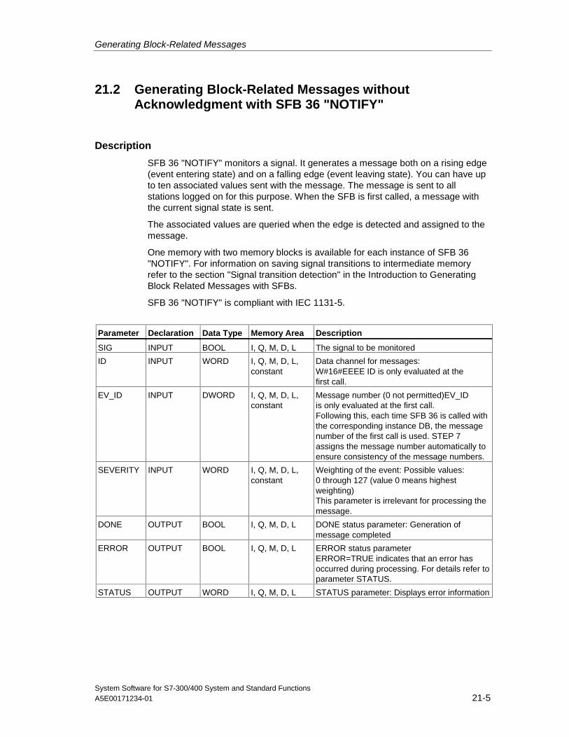
Generating Block-Related Messages
System Software for S7-300/400 System and Standard FunctionsA5E00171234-01 21-5
21.2 Generating Block-Related Messages withoutAcknowledgment with SFB 36 "NOTIFY"
Description
SFB 36 "NOTIFY" monitors a signal. It generates a message both on a rising edge(event entering state) and on a falling edge (event leaving state). You can have upto ten associated values sent with the message. The message is sent to allstations logged on for this purpose. When the SFB is first called, a message withthe current signal state is sent.
The associated values are queried when the edge is detected and assigned to themessage.
One memory with two memory blocks is available for each instance of SFB 36"NOTIFY". For information on saving signal transitions to intermediate memoryrefer to the section "Signal transition detection" in the Introduction to GeneratingBlock Related Messages with SFBs.
SFB 36 "NOTIFY" is compliant with IEC 1131-5.
Parameter Declaration Data Type Memory Area Description
SIG INPUT BOOL I, Q, M, D, L The signal to be monitored
ID INPUT WORD I, Q, M, D, L,constant
Data channel for messages:W#16#EEEE ID is only evaluated at thefirst call.
EV_ID INPUT DWORD I, Q, M, D, L,constant
Message number (0 not permitted)EV_IDis only evaluated at the first call.Following this, each time SFB 36 is called withthe corresponding instance DB, the messagenumber of the first call is used. STEP 7assigns the message number automatically toensure consistency of the message numbers.
SEVERITY INPUT WORD I, Q, M, D, L,constant
Weighting of the event: Possible values:0 through 127 (value 0 means highestweighting)This parameter is irrelevant for processing themessage.
DONE OUTPUT BOOL I, Q, M, D, L DONE status parameter: Generation ofmessage completed
ERROR OUTPUT BOOL I, Q, M, D, L ERROR status parameterERROR=TRUE indicates that an error hasoccurred during processing. For details refer toparameter STATUS.
STATUS OUTPUT WORD I, Q, M, D, L STATUS parameter: Displays error information
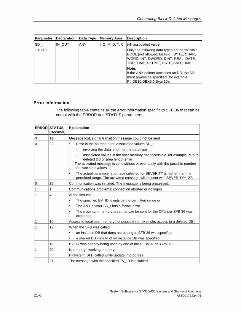
Generating Block-Related Messages
System Software for S7-300/400 System and Standard Functions21-6 A5E00171234-01
Parameter Declaration Data Type Memory Area Description
SD_i,
1≤i ≤10
IN_OUT ANY I, Q, M, D, T, C i-th associated value
Only the following data types are permissible:BOOL (not allowed: bit field), BYTE, CHAR,WORD, INT, DWORD, DINT, REAL, DATE,TOD, TIME, S5TIME, DATE_AND_TIME.
Note:If the ANY pointer accesses an DB, the DBmust always be specified (for example:P# DB10.DBX5.0 Byte 10).
Error Information
The following table contains all the error information specific to SFB 36 that can beoutput with the ERROR and STATUS parameters.
ERROR STATUS(Decimal)
Explanation
0 11 Message lost, signal transition/message could not be sent
0 22 • Error in the pointer to the associated values SD_i:
- involving the data length or the data type
- associated values in the user memory not accessible, for example, due todeleted DB or area length error
The activated message is sent without or eventually with the possible numberof associated values
• The actual parameter you have selected for SEVERITY is higher than thepermitted range. The activated message will be sent with SEVERITY=127.
0 25 Communication was initiated. The message is being processed.
1 1 Communications problems: connection aborted or no logon
1 4 At the first call:
• The specified EV_ID is outside the permitted range or
• The ANY pointer SD_i has a formal error
• The maximum memory area that can be sent for the CPU per SFB 36 wasexceeded
1 10 Access to local user memory not possible (for example, access to a deleted DB)
1 12 When the SFB was called:
• an instance DB that does not belong to SFB 36 was specified
• a shared DB instead of an instance DB was specified
1 18 EV_ID was already being used by one of the SFBs 31 or 33 to 36.
1 20 Not enough working memory.
H-System: SFB called while update in progress
1 21 The message with the specified EV_ID is disabled
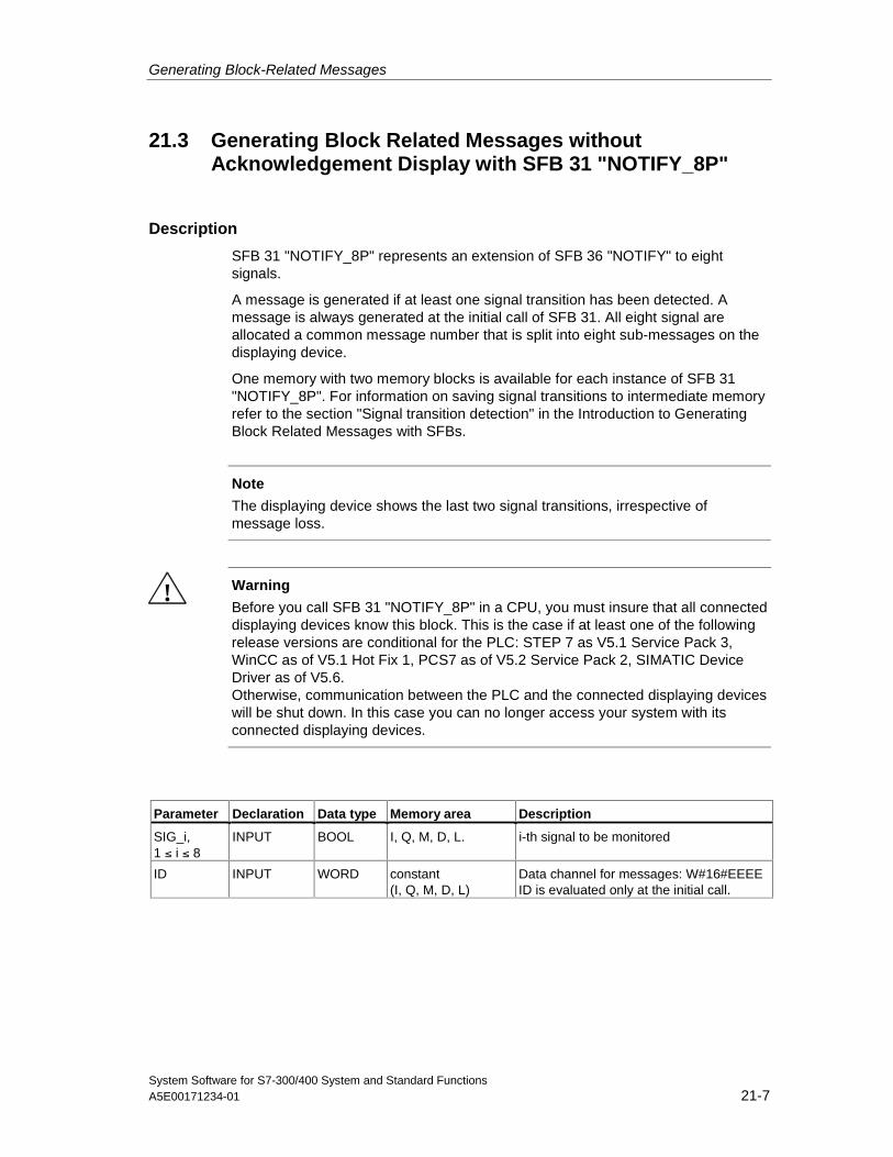
Generating Block-Related Messages
System Software for S7-300/400 System and Standard FunctionsA5E00171234-01 21-7
21.3 Generating Block Related Messages withoutAcknowledgement Display with SFB 31 "NOTIFY_8P"
Description
SFB 31 "NOTIFY_8P" represents an extension of SFB 36 "NOTIFY" to eightsignals.
A message is generated if at least one signal transition has been detected. Amessage is always generated at the initial call of SFB 31. All eight signal areallocated a common message number that is split into eight sub-messages on thedisplaying device.
One memory with two memory blocks is available for each instance of SFB 31"NOTIFY_8P". For information on saving signal transitions to intermediate memoryrefer to the section "Signal transition detection" in the Introduction to GeneratingBlock Related Messages with SFBs.
Note
The displaying device shows the last two signal transitions, irrespective ofmessage loss.
! Warning
Before you call SFB 31 "NOTIFY_8P" in a CPU, you must insure that all connecteddisplaying devices know this block. This is the case if at least one of the followingrelease versions are conditional for the PLC: STEP 7 as V5.1 Service Pack 3,WinCC as of V5.1 Hot Fix 1, PCS7 as of V5.2 Service Pack 2, SIMATIC DeviceDriver as of V5.6.Otherwise, communication between the PLC and the connected displaying deviceswill be shut down. In this case you can no longer access your system with itsconnected displaying devices.
Parameter Declaration Data type Memory area Description
SIG_i,1 ≤ i ≤ 8
INPUT BOOL I, Q, M, D, L. i-th signal to be monitored
ID INPUT WORD constant(I, Q, M, D, L)
Data channel for messages: W#16#EEEEID is evaluated only at the initial call.
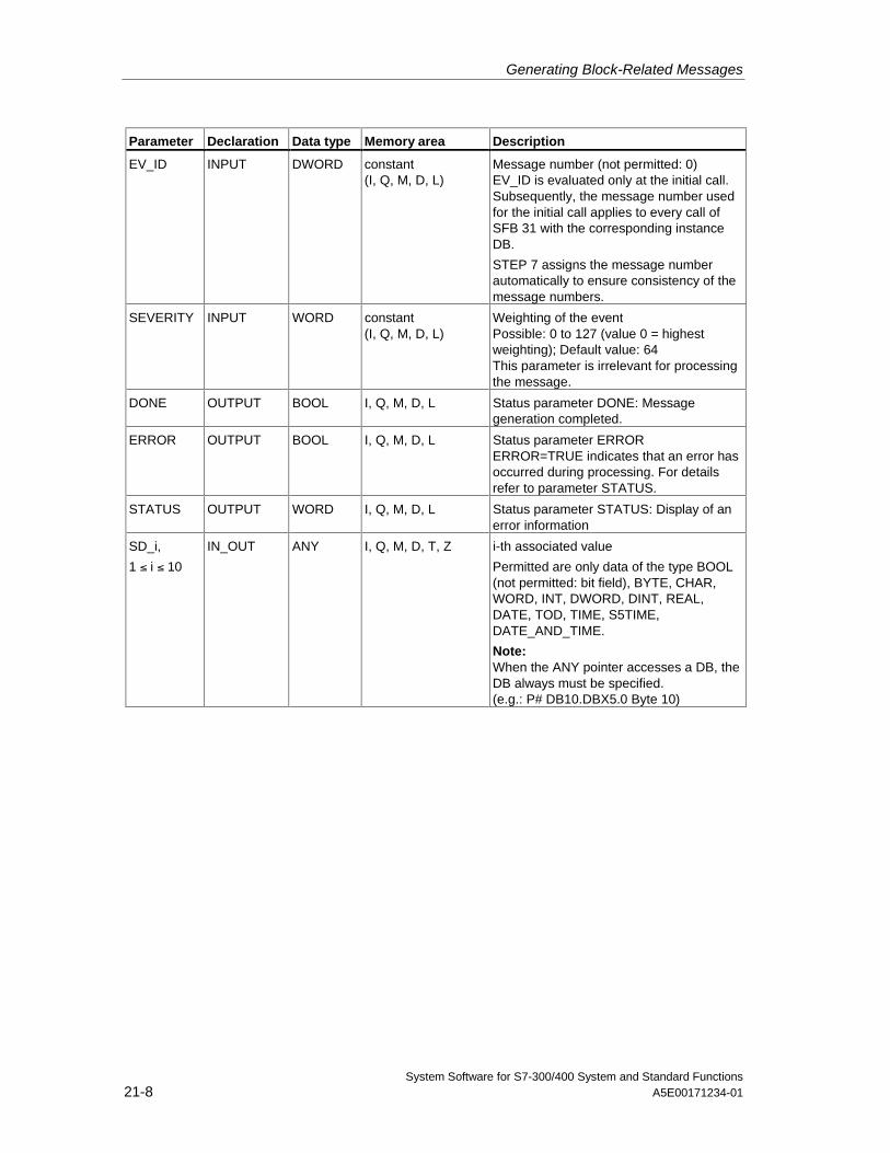
Generating Block-Related Messages
System Software for S7-300/400 System and Standard Functions21-8 A5E00171234-01
Parameter Declaration Data type Memory area Description
EV_ID INPUT DWORD constant(I, Q, M, D, L)
Message number (not permitted: 0)EV_ID is evaluated only at the initial call.Subsequently, the message number usedfor the initial call applies to every call ofSFB 31 with the corresponding instanceDB.
STEP 7 assigns the message numberautomatically to ensure consistency of themessage numbers.
SEVERITY INPUT WORD constant(I, Q, M, D, L)
Weighting of the eventPossible: 0 to 127 (value 0 = highestweighting); Default value: 64This parameter is irrelevant for processingthe message.
DONE OUTPUT BOOL I, Q, M, D, L Status parameter DONE: Messagegeneration completed.
ERROR OUTPUT BOOL I, Q, M, D, L Status parameter ERRORERROR=TRUE indicates that an error hasoccurred during processing. For detailsrefer to parameter STATUS.
STATUS OUTPUT WORD I, Q, M, D, L Status parameter STATUS: Display of anerror information
SD_i,
1 ≤ i ≤ 10
IN_OUT ANY I, Q, M, D, T, Z i-th associated value
Permitted are only data of the type BOOL(not permitted: bit field), BYTE, CHAR,WORD, INT, DWORD, DINT, REAL,DATE, TOD, TIME, S5TIME,DATE_AND_TIME.
Note:When the ANY pointer accesses a DB, theDB always must be specified.(e.g.: P# DB10.DBX5.0 Byte 10)
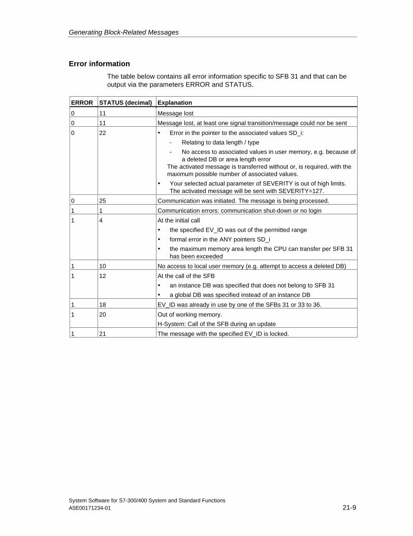
Generating Block-Related Messages
System Software for S7-300/400 System and Standard FunctionsA5E00171234-01 21-9
Error information
The table below contains all error information specific to SFB 31 and that can beoutput via the parameters ERROR and STATUS.
ERROR STATUS (decimal) Explanation
0 11 Message lost
0 11 Message lost, at least one signal transition/message could nor be sent
0 22 • Error in the pointer to the associated values SD_i:
- Relating to data length / type
- No access to associated values in user memory, e.g. because ofa deleted DB or area length error
The activated message is transferred without or, is required, with themaximum possible number of associated values.
• Your selected actual parameter of SEVERITY is out of high limits.The activated message will be sent with SEVERITY=127.
0 25 Communication was initiated. The message is being processed.
1 1 Communication errors: communication shut-down or no login
1 4 At the initial call
• the specified EV_ID was out of the permitted range
• formal error in the ANY pointers SD_i
• the maximum memory area length the CPU can transfer per SFB 31has been exceeded
1 10 No access to local user memory (e.g. attempt to access a deleted DB)
1 12 At the call of the SFB
• an instance DB was specified that does not belong to SFB 31
• a global DB was specified instead of an instance DB
1 18 EV_ID was already in use by one of the SFBs 31 or 33 to 36.
1 20 Out of working memory.
H-System: Call of the SFB during an update
1 21 The message with the specified EV_ID is locked.
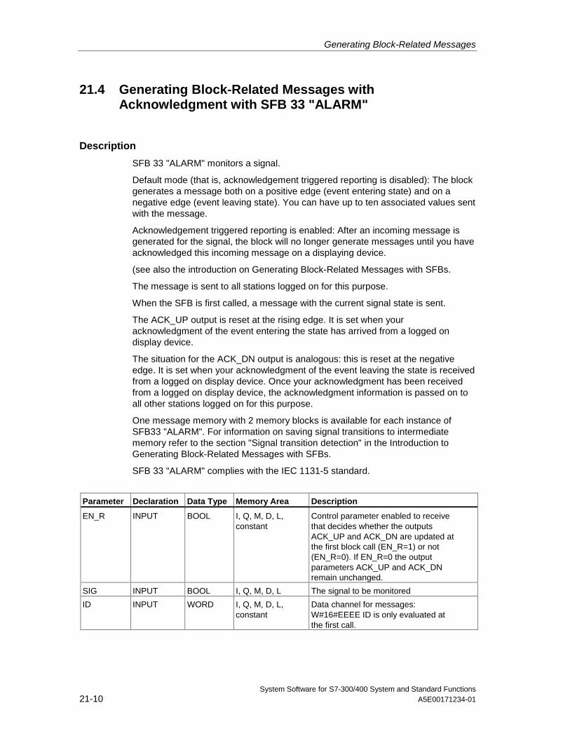
Generating Block-Related Messages
System Software for S7-300/400 System and Standard Functions21-10 A5E00171234-01
21.4 Generating Block-Related Messages withAcknowledgment with SFB 33 "ALARM"
Description
SFB 33 "ALARM" monitors a signal.
Default mode (that is, acknowledgement triggered reporting is disabled): The blockgenerates a message both on a positive edge (event entering state) and on anegative edge (event leaving state). You can have up to ten associated values sentwith the message.
Acknowledgement triggered reporting is enabled: After an incoming message isgenerated for the signal, the block will no longer generate messages until you haveacknowledged this incoming message on a displaying device.
(see also the introduction on Generating Block-Related Messages with SFBs.
The message is sent to all stations logged on for this purpose.
When the SFB is first called, a message with the current signal state is sent.
The ACK_UP output is reset at the rising edge. It is set when youracknowledgment of the event entering the state has arrived from a logged ondisplay device.
The situation for the ACK_DN output is analogous: this is reset at the negativeedge. It is set when your acknowledgment of the event leaving the state is receivedfrom a logged on display device. Once your acknowledgment has been receivedfrom a logged on display device, the acknowledgment information is passed on toall other stations logged on for this purpose.
One message memory with 2 memory blocks is available for each instance ofSFB33 "ALARM". For information on saving signal transitions to intermediatememory refer to the section "Signal transition detection" in the Introduction toGenerating Block-Related Messages with SFBs.
SFB 33 "ALARM" complies with the IEC 1131-5 standard.
Parameter Declaration Data Type Memory Area Description
EN_R INPUT BOOL I, Q, M, D, L,constant
Control parameter enabled to receivethat decides whether the outputsACK_UP and ACK_DN are updated atthe first block call (EN_R=1) or not(EN_R=0). If EN_R=0 the outputparameters ACK_UP and ACK_DNremain unchanged.
SIG INPUT BOOL I, Q, M, D, L The signal to be monitored
ID INPUT WORD I, Q, M, D, L,constant
Data channel for messages:W#16#EEEE ID is only evaluated atthe first call.
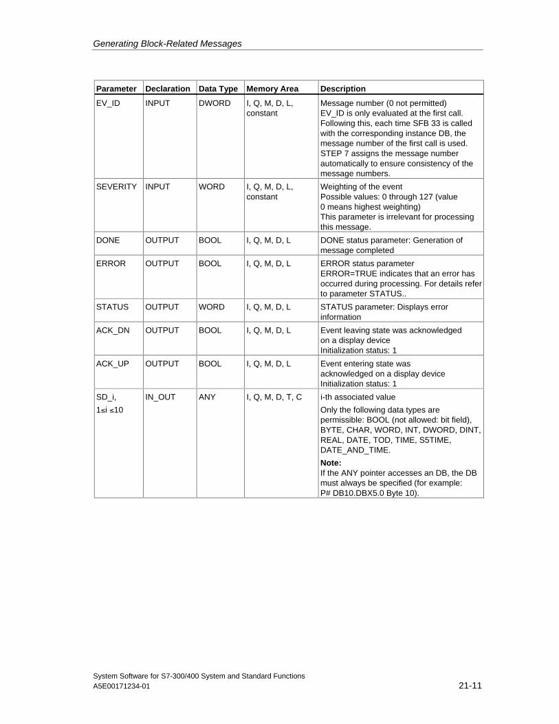
Generating Block-Related Messages
System Software for S7-300/400 System and Standard FunctionsA5E00171234-01 21-11
Parameter Declaration Data Type Memory Area Description
EV_ID INPUT DWORD I, Q, M, D, L,constant
Message number (0 not permitted)EV_ID is only evaluated at the first call.Following this, each time SFB 33 is calledwith the corresponding instance DB, themessage number of the first call is used.STEP 7 assigns the message numberautomatically to ensure consistency of themessage numbers.
SEVERITY INPUT WORD I, Q, M, D, L,constant
Weighting of the eventPossible values: 0 through 127 (value0 means highest weighting)This parameter is irrelevant for processingthis message.
DONE OUTPUT BOOL I, Q, M, D, L DONE status parameter: Generation ofmessage completed
ERROR OUTPUT BOOL I, Q, M, D, L ERROR status parameterERROR=TRUE indicates that an error hasoccurred during processing. For details referto parameter STATUS..
STATUS OUTPUT WORD I, Q, M, D, L STATUS parameter: Displays errorinformation
ACK_DN OUTPUT BOOL I, Q, M, D, L Event leaving state was acknowledgedon a display deviceInitialization status: 1
ACK_UP OUTPUT BOOL I, Q, M, D, L Event entering state wasacknowledged on a display deviceInitialization status: 1
SD_i,
1≤i ≤10
IN_OUT ANY I, Q, M, D, T, C i-th associated value
Only the following data types arepermissible: BOOL (not allowed: bit field),BYTE, CHAR, WORD, INT, DWORD, DINT,REAL, DATE, TOD, TIME, S5TIME,DATE_AND_TIME.
Note:If the ANY pointer accesses an DB, the DBmust always be specified (for example:P# DB10.DBX5.0 Byte 10).
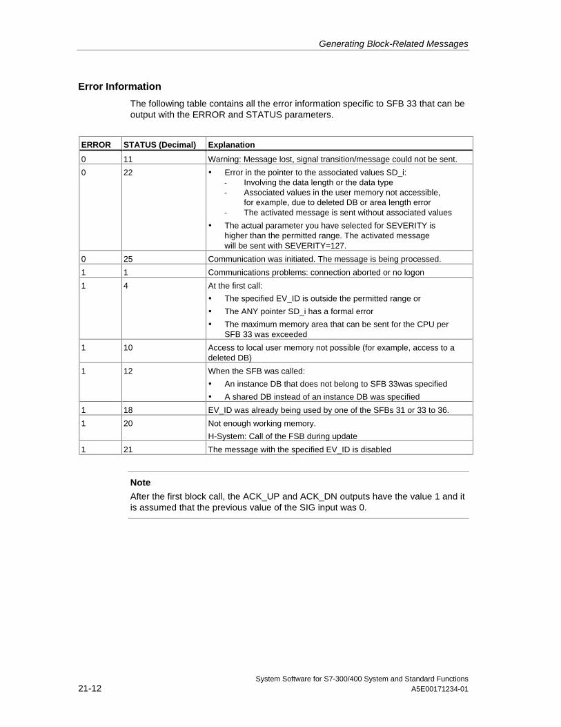
Generating Block-Related Messages
System Software for S7-300/400 System and Standard Functions21-12 A5E00171234-01
Error Information
The following table contains all the error information specific to SFB 33 that can beoutput with the ERROR and STATUS parameters.
ERROR STATUS (Decimal) Explanation
0 11 Warning: Message lost, signal transition/message could not be sent.
0 22 • Error in the pointer to the associated values SD_i:- Involving the data length or the data type- Associated values in the user memory not accessible,
for example, due to deleted DB or area length error- The activated message is sent without associated values
• The actual parameter you have selected for SEVERITY ishigher than the permitted range. The activated messagewill be sent with SEVERITY=127.
0 25 Communication was initiated. The message is being processed.
1 1 Communications problems: connection aborted or no logon
1 4 At the first call:
• The specified EV_ID is outside the permitted range or
• The ANY pointer SD_i has a formal error
• The maximum memory area that can be sent for the CPU perSFB 33 was exceeded
1 10 Access to local user memory not possible (for example, access to adeleted DB)
1 12 When the SFB was called:
• An instance DB that does not belong to SFB 33was specified
• A shared DB instead of an instance DB was specified
1 18 EV_ID was already being used by one of the SFBs 31 or 33 to 36.
1 20 Not enough working memory.
H-System: Call of the FSB during update
1 21 The message with the specified EV_ID is disabled
Note
After the first block call, the ACK_UP and ACK_DN outputs have the value 1 and itis assumed that the previous value of the SIG input was 0.
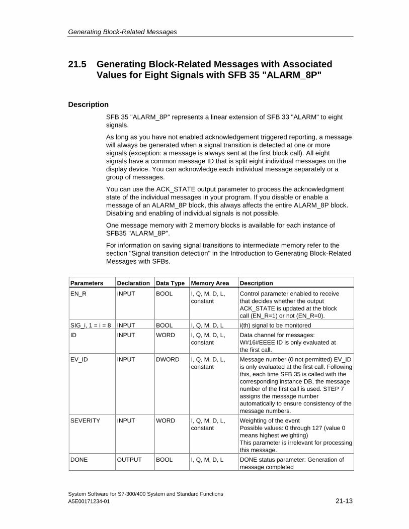
Generating Block-Related Messages
System Software for S7-300/400 System and Standard FunctionsA5E00171234-01 21-13
21.5 Generating Block-Related Messages with AssociatedValues for Eight Signals with SFB 35 "ALARM_8P"
Description
SFB 35 "ALARM_8P" represents a linear extension of SFB 33 "ALARM" to eightsignals.
As long as you have not enabled acknowledgement triggered reporting, a messagewill always be generated when a signal transition is detected at one or moresignals (exception: a message is always sent at the first block call). All eightsignals have a common message ID that is split eight individual messages on thedisplay device. You can acknowledge each individual message separately or agroup of messages.
You can use the ACK_STATE output parameter to process the acknowledgmentstate of the individual messages in your program. If you disable or enable amessage of an ALARM_8P block, this always affects the entire ALARM_8P block.Disabling and enabling of individual signals is not possible.
One message memory with 2 memory blocks is available for each instance ofSFB35 "ALARM_8P".
For information on saving signal transitions to intermediate memory refer to thesection "Signal transition detection" in the Introduction to Generating Block-RelatedMessages with SFBs.
Parameters Declaration Data Type Memory Area Description
EN_R INPUT BOOL I, Q, M, D, L,constant
Control parameter enabled to receivethat decides whether the outputACK_STATE is updated at the blockcall (EN_R=1) or not (EN_R=0).
SIG_i, 1 = i = 8 INPUT BOOL I, Q, M, D, L i(th) signal to be monitored
ID INPUT WORD I, Q, M, D, L,constant
Data channel for messages:W#16#EEEE ID is only evaluated atthe first call.
EV_ID INPUT DWORD I, Q, M, D, L,constant
Message number (0 not permitted) EV_IDis only evaluated at the first call. Followingthis, each time SFB 35 is called with thecorresponding instance DB, the messagenumber of the first call is used. STEP 7assigns the message numberautomatically to ensure consistency of themessage numbers.
SEVERITY INPUT WORD I, Q, M, D, L,constant
Weighting of the eventPossible values: 0 through 127 (value 0means highest weighting)This parameter is irrelevant for processingthis message.
DONE OUTPUT BOOL I, Q, M, D, L DONE status parameter: Generation ofmessage completed
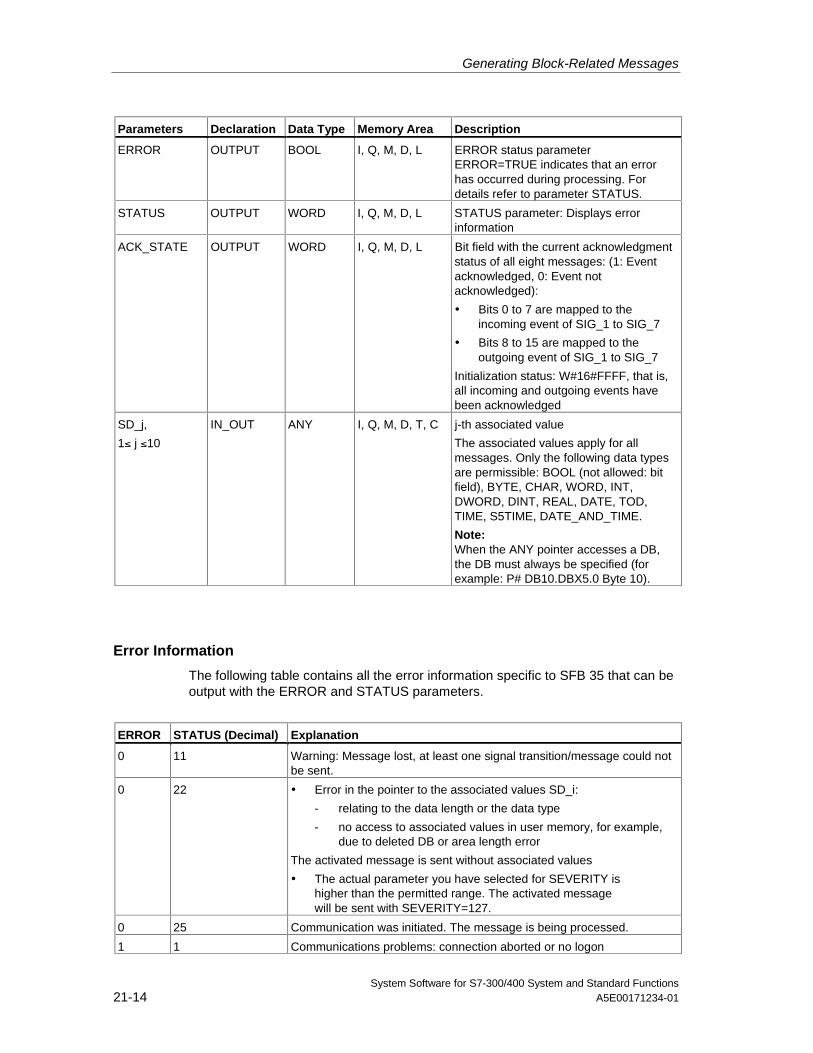
Generating Block-Related Messages
System Software for S7-300/400 System and Standard Functions21-14 A5E00171234-01
Parameters Declaration Data Type Memory Area Description
ERROR OUTPUT BOOL I, Q, M, D, L ERROR status parameterERROR=TRUE indicates that an errorhas occurred during processing. Fordetails refer to parameter STATUS.
STATUS OUTPUT WORD I, Q, M, D, L STATUS parameter: Displays errorinformation
ACK_STATE OUTPUT WORD I, Q, M, D, L Bit field with the current acknowledgmentstatus of all eight messages: (1: Eventacknowledged, 0: Event notacknowledged):
• Bits 0 to 7 are mapped to theincoming event of SIG_1 to SIG_7
• Bits 8 to 15 are mapped to theoutgoing event of SIG_1 to SIG_7
Initialization status: W#16#FFFF, that is,all incoming and outgoing events havebeen acknowledged
SD_j,
1≤ j ≤10
IN_OUT ANY I, Q, M, D, T, C j-th associated value
The associated values apply for allmessages. Only the following data typesare permissible: BOOL (not allowed: bitfield), BYTE, CHAR, WORD, INT,DWORD, DINT, REAL, DATE, TOD,TIME, S5TIME, DATE_AND_TIME.
Note:When the ANY pointer accesses a DB,the DB must always be specified (forexample: P# DB10.DBX5.0 Byte 10).
Error Information
The following table contains all the error information specific to SFB 35 that can beoutput with the ERROR and STATUS parameters.
ERROR STATUS (Decimal) Explanation
0 11 Warning: Message lost, at least one signal transition/message could notbe sent.
0 22 • Error in the pointer to the associated values SD_i:
- relating to the data length or the data type
- no access to associated values in user memory, for example,due to deleted DB or area length error
The activated message is sent without associated values
• The actual parameter you have selected for SEVERITY ishigher than the permitted range. The activated messagewill be sent with SEVERITY=127.
0 25 Communication was initiated. The message is being processed.
1 1 Communications problems: connection aborted or no logon
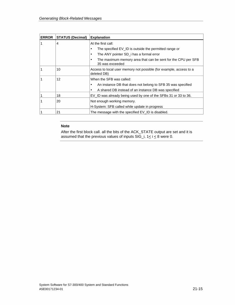
Generating Block-Related Messages
System Software for S7-300/400 System and Standard FunctionsA5E00171234-01 21-15
ERROR STATUS (Decimal) Explanation
1 4 At the first call:
• The specified EV_ID is outside the permitted range or
• The ANY pointer SD_i has a formal error
• The maximum memory area that can be sent for the CPU per SFB35 was exceeded
1 10 Access to local user memory not possible (for example, access to adeleted DB)
1 12 When the SFB was called:
• An instance DB that does not belong to SFB 35 was specified
• A shared DB instead of an instance DB was specified
1 18 EV_ID was already being used by one of the SFBs 31 or 33 to 36.
1 20 Not enough working memory.
H-System: SFB called while update in progress
1 21 The message with the specified EV_ID is disabled.
Note
After the first block call. all the bits of the ACK_STATE output are set and it isassumed that the previous values of inputs SIG_i, 1< i < 8 were 0.
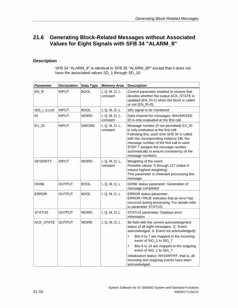
Generating Block-Related Messages
System Software for S7-300/400 System and Standard Functions21-16 A5E00171234-01
21.6 Generating Block-Related Messages without AssociatedValues for Eight Signals with SFB 34 "ALARM_8"
Description
SFB 34 "ALARM_8" is identical to SFB 35 "ALARM_8P" except that it does nothave the associated values SD_1 through SD_10.
Parameter Declaration Data Type Memory Area Description
EN_R INPUT BOOL I, Q, M, D, L,constant
Control parameter enabled to receive thatdecides whether the output ACK_STATE isupdated (EN_R=1) when the block is calledor not (EN_R=0).
SIG_i, 1<i<8 INPUT BOOL I, Q, M, D, L i(th) signal to be monitored
ID INPUT WORD I, Q, M, D, L,constant
Data channel for messages: W#16#EEEEID is only evaluated at the first call.
EV_ID INPUT DWORD I, Q, M, D, L,constant
Message number (0 not permitted) EV_IDis only evaluated at the first call.Following this, each time SFB 34 is calledwith the corresponding instance DB, themessage number of the first call is used.STEP 7 assigns the message numberautomatically to ensure consistency of themessage numbers.
SEVERITY INPUT WORD I, Q, M, D, L,constant
Weighting of the eventPossible values: 0 through 127 (value 0means highest weighting)This parameter is irrelevant processing thismessage.
DONE OUTPUT BOOL I, Q, M, D, L DONE status parameter: Generation ofmessage completed
ERROR OUTPUT BOOL I, Q, M, D, L ERROR status parameterERROR=TRUE indicates that an error hasoccurred during processing. For details referto parameter STATUS.
STATUS OUTPUT WORD I, Q, M, D, L STATUS parameter: Displays errorinformation
ACK_STATE OUTPUT WORD I, Q, M, D, L Bit field with the current acknowledgmentstatus of all eight messages: (1: Eventacknowledged, 0: Event not acknowledged):
• Bits 0 to 7 are mapped to the incomingevent of SIG_1 to SIG_7
• Bits 8 to 15 are mapped to the outgoingevent of SIG_1 to SIG_7
Initialization status: W#16#FFFF, that is, allincoming and outgoing events have beenacknowledged
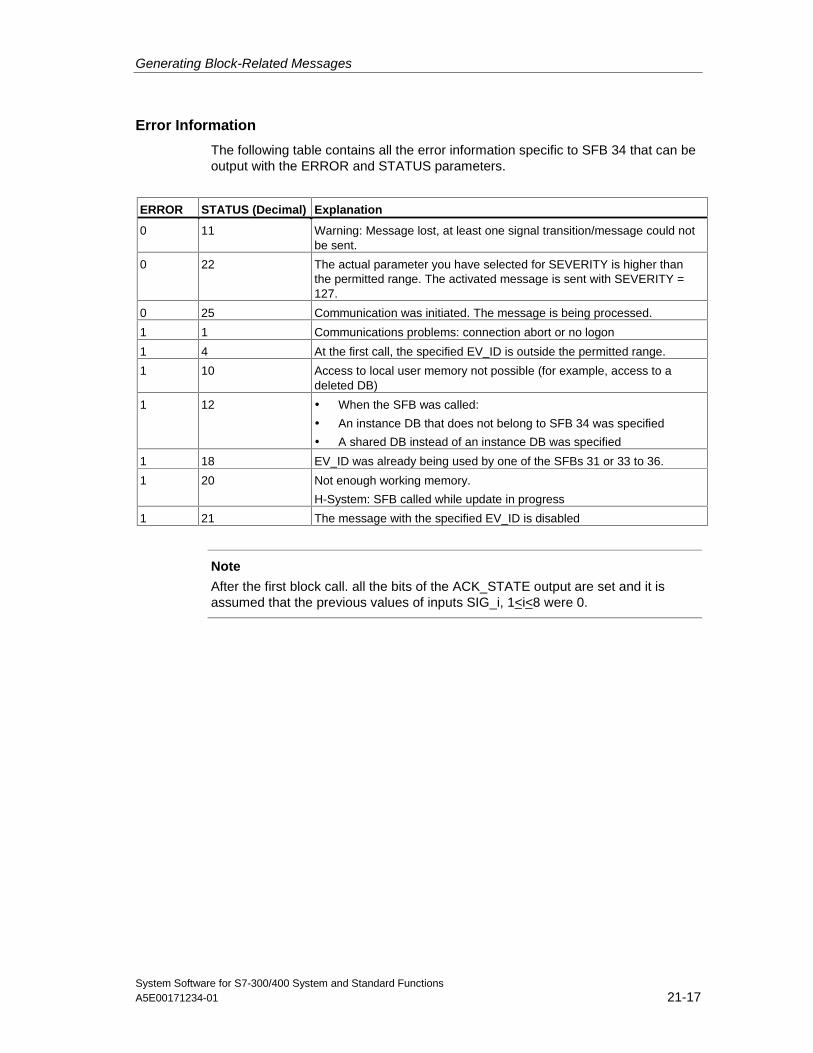
Generating Block-Related Messages
System Software for S7-300/400 System and Standard FunctionsA5E00171234-01 21-17
Error Information
The following table contains all the error information specific to SFB 34 that can beoutput with the ERROR and STATUS parameters.
ERROR STATUS (Decimal) Explanation
0 11 Warning: Message lost, at least one signal transition/message could notbe sent.
0 22 The actual parameter you have selected for SEVERITY is higher thanthe permitted range. The activated message is sent with SEVERITY = 127.
0 25 Communication was initiated. The message is being processed.
1 1 Communications problems: connection abort or no logon
1 4 At the first call, the specified EV_ID is outside the permitted range.
1 10 Access to local user memory not possible (for example, access to adeleted DB)
1 12 • When the SFB was called:
• An instance DB that does not belong to SFB 34 was specified
• A shared DB instead of an instance DB was specified
1 18 EV_ID was already being used by one of the SFBs 31 or 33 to 36.
1 20 Not enough working memory.
H-System: SFB called while update in progress
1 21 The message with the specified EV_ID is disabled
Note
After the first block call. all the bits of the ACK_STATE output are set and it isassumed that the previous values of inputs SIG_i, 1<i< 8 were 0.
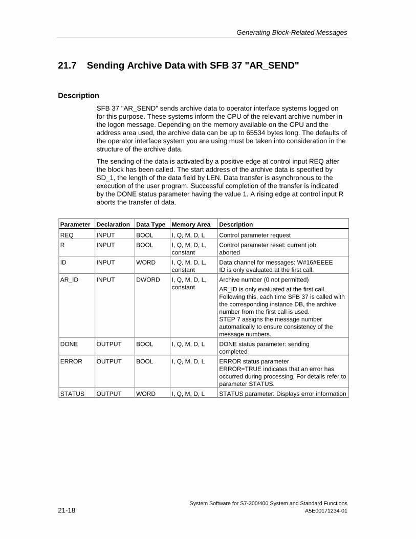
Generating Block-Related Messages
System Software for S7-300/400 System and Standard Functions21-18 A5E00171234-01
21.7 Sending Archive Data with SFB 37 "AR_SEND"
Description
SFB 37 "AR_SEND" sends archive data to operator interface systems logged onfor this purpose. These systems inform the CPU of the relevant archive number inthe logon message. Depending on the memory available on the CPU and theaddress area used, the archive data can be up to 65534 bytes long. The defaults ofthe operator interface system you are using must be taken into consideration in thestructure of the archive data.
The sending of the data is activated by a positive edge at control input REQ afterthe block has been called. The start address of the archive data is specified bySD_1, the length of the data field by LEN. Data transfer is asynchronous to theexecution of the user program. Successful completion of the transfer is indicatedby the DONE status parameter having the value 1. A rising edge at control input Raborts the transfer of data.
Parameter Declaration Data Type Memory Area Description
REQ INPUT BOOL I, Q, M, D, L Control parameter request
R INPUT BOOL I, Q, M, D, L,constant
Control parameter reset: current jobaborted
ID INPUT WORD I, Q, M, D, L,constant
Data channel for messages: W#16#EEEEID is only evaluated at the first call.
AR_ID INPUT DWORD I, Q, M, D, L,constant
Archive number (0 not permitted)
AR_ID is only evaluated at the first call.Following this, each time SFB 37 is called withthe corresponding instance DB, the archivenumber from the first call is used.STEP 7 assigns the message numberautomatically to ensure consistency of themessage numbers.
DONE OUTPUT BOOL I, Q, M, D, L DONE status parameter: sendingcompleted
ERROR OUTPUT BOOL I, Q, M, D, L ERROR status parameterERROR=TRUE indicates that an error hasoccurred during processing. For details refer toparameter STATUS.
STATUS OUTPUT WORD I, Q, M, D, L STATUS parameter: Displays error information
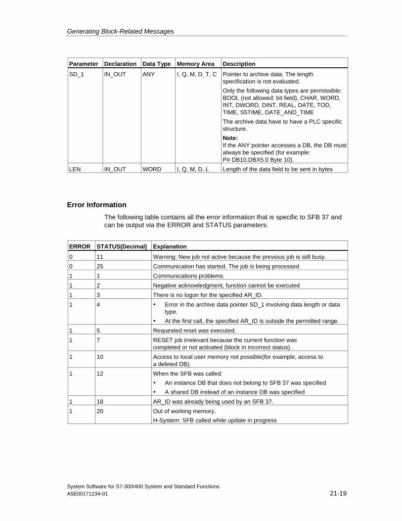
Generating Block-Related Messages
System Software for S7-300/400 System and Standard FunctionsA5E00171234-01 21-19
Parameter Declaration Data Type Memory Area Description
SD_1 IN_OUT ANY I, Q, M, D, T, C Pointer to archive data. The lengthspecification is not evaluated.
Only the following data types are permissible:BOOL (not allowed: bit field), CHAR, WORD,INT, DWORD, DINT, REAL, DATE, TOD,TIME, S5TIME, DATE_AND_TIME
The archive data have to have a PLC specificstructure.
Note:If the ANY pointer accesses a DB, the DB mustalways be specified (for example:P# DB10.DBX5.0 Byte 10).
LEN IN_OUT WORD I, Q, M, D, L Length of the data field to be sent in bytes
Error Information
The following table contains all the error information that is specific to SFB 37 andcan be output via the ERROR and STATUS parameters.
ERROR STATUS(Decimal) Explanation
0 11 Warning: New job not active because the previous job is still busy.
0 25 Communication has started. The job is being processed.
1 1 Communications problems
1 2 Negative acknowledgment, function cannot be executed
1 3 There is no logon for the specified AR_ID.
1 4 • Error in the archive data pointer SD_1 involving data length or datatype.
• At the first call, the specified AR_ID is outside the permitted range.
1 5 Requested reset was executed.
1 7 RESET job irrelevant because the current function wascompleted or not activated (block in incorrect status).
1 10 Access to local user memory not possible(for example, access toa deleted DB).
1 12 When the SFB was called:
• An instance DB that does not belong to SFB 37 was specified
• A shared DB instead of an instance DB was specified
1 18 AR_ID was already being used by an SFB 37.
1 20 Out of working memory.
H-System: SFB called while update in progress
Generating Block-Related Messages
System Software for S7-300/400 System and Standard Functions21-20 A5E00171234-01
21.8 Disabling Block-Related, Symbol-Related and GroupStatus Messages with SFC 10 "DIS_MSG"
Description
With SFC 10 "DIS_MSG" (disable message) you can disable block-relatedmessages generated with SFBs, symbol-related messages (SCAN) and groupstatus messages. You select messages to be disabled using the input parametersMODE and MESGN. Calling SFC 10 "DIS_MSG" and successfully disabling amessage is only possible when the disabling of a message is not already activewith SFC 10.
Messages that are ready to be sent when SFC 10 is called but that are still in aninternal buffer can no longer be disabled and are sent. A disabled message isindicated at the ERROR and STATUS outputs of the "NOTIFY", "NOTIFY_8P","ALARM", "ALARM_8P" and "ALARM_8" SFBs.
You start the disabling of a message by assigning the value 1 to the REQ inputparameter when SFC 10 is called.
How SFC 10 Functions
Disabling is executed asynchronously, in other words it can be active throughoutseveral SFC 10 calls:
• When it is first called (REQ =1), SFC 10 checks the input parameters andattempts to occupy the required system resources. If successful, the valueW#16#7001 is entered in RET_VAL, BUSY is set and disabling the message isstarted.If unsuccessful, the error information is entered in RET_VAL and the job isterminated. BUSY must not be evaluated in this case.
• If there are further calls in the meantime, the value W#16#7002 is entered inRET_VAL (job still being executed by the CPU) and BUSY is set. Further callsdo not affect the current job.
• The last time the SFB is called, the value W#16#0000 is entered in RET_VAL ifno error occurred. BUSY then has the value 0. If an error occurred, the errorinformation is entered in RET_VAL and BUSY must not be evaluated.
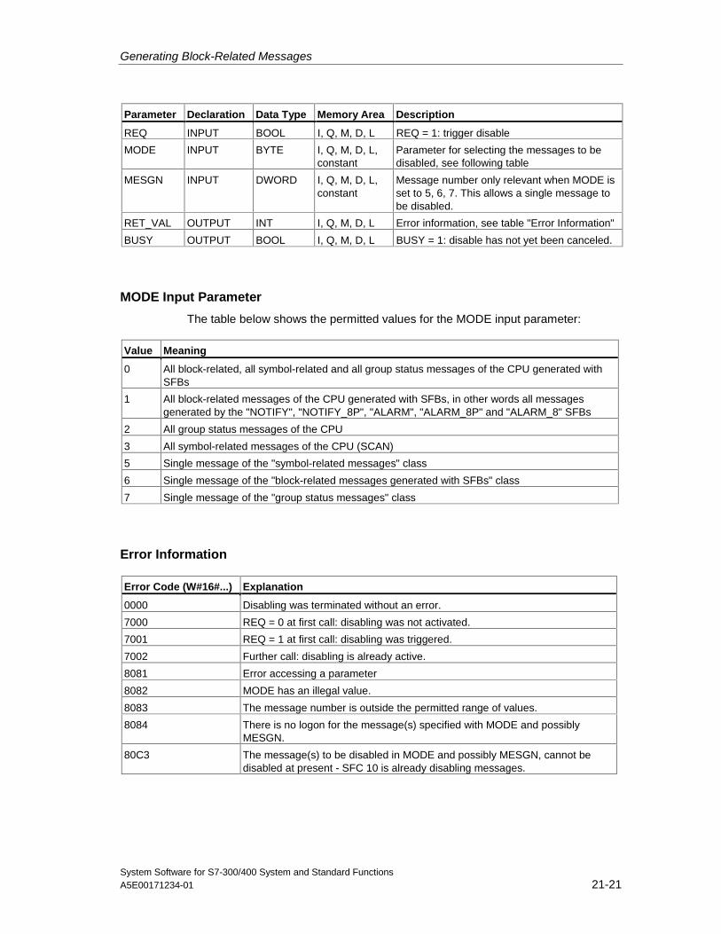
Generating Block-Related Messages
System Software for S7-300/400 System and Standard FunctionsA5E00171234-01 21-21
Parameter Declaration Data Type Memory Area Description
REQ INPUT BOOL I, Q, M, D, L REQ = 1: trigger disable
MODE INPUT BYTE I, Q, M, D, L,constant
Parameter for selecting the messages to bedisabled, see following table
MESGN INPUT DWORD I, Q, M, D, L,constant
Message number only relevant when MODE isset to 5, 6, 7. This allows a single message tobe disabled.
RET_VAL OUTPUT INT I, Q, M, D, L Error information, see table "Error Information"
BUSY OUTPUT BOOL I, Q, M, D, L BUSY = 1: disable has not yet been canceled.
MODE Input Parameter
The table below shows the permitted values for the MODE input parameter:
Value Meaning
0 All block-related, all symbol-related and all group status messages of the CPU generated withSFBs
1 All block-related messages of the CPU generated with SFBs, in other words all messagesgenerated by the "NOTIFY", "NOTIFY_8P", "ALARM", "ALARM_8P" and "ALARM_8" SFBs
2 All group status messages of the CPU
3 All symbol-related messages of the CPU (SCAN)
5 Single message of the "symbol-related messages" class
6 Single message of the "block-related messages generated with SFBs" class
7 Single message of the "group status messages" class
Error Information
Error Code (W#16#...) Explanation
0000 Disabling was terminated without an error.
7000 REQ = 0 at first call: disabling was not activated.
7001 REQ = 1 at first call: disabling was triggered.
7002 Further call: disabling is already active.
8081 Error accessing a parameter
8082 MODE has an illegal value.
8083 The message number is outside the permitted range of values.
8084 There is no logon for the message(s) specified with MODE and possiblyMESGN.
80C3 The message(s) to be disabled in MODE and possibly MESGN, cannot bedisabled at present - SFC 10 is already disabling messages.
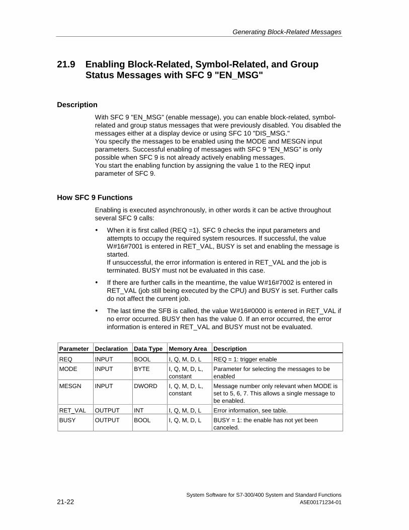
Generating Block-Related Messages
System Software for S7-300/400 System and Standard Functions21-22 A5E00171234-01
21.9 Enabling Block-Related, Symbol-Related, and GroupStatus Messages with SFC 9 "EN_MSG"
Description
With SFC 9 "EN_MSG" (enable message), you can enable block-related, symbol-related and group status messages that were previously disabled. You disabled themessages either at a display device or using SFC 10 "DIS_MSG."You specify the messages to be enabled using the MODE and MESGN inputparameters. Successful enabling of messages with SFC 9 "EN_MSG" is onlypossible when SFC 9 is not already actively enabling messages.You start the enabling function by assigning the value 1 to the REQ inputparameter of SFC 9.
How SFC 9 Functions
Enabling is executed asynchronously, in other words it can be active throughoutseveral SFC 9 calls:
• When it is first called (REQ =1), SFC 9 checks the input parameters andattempts to occupy the required system resources. If successful, the valueW#16#7001 is entered in RET_VAL, BUSY is set and enabling the message isstarted.If unsuccessful, the error information is entered in RET_VAL and the job isterminated. BUSY must not be evaluated in this case.
• If there are further calls in the meantime, the value W#16#7002 is entered inRET_VAL (job still being executed by the CPU) and BUSY is set. Further callsdo not affect the current job.
• The last time the SFB is called, the value W#16#0000 is entered in RET_VAL ifno error occurred. BUSY then has the value 0. If an error occurred, the errorinformation is entered in RET_VAL and BUSY must not be evaluated.
Parameter Declaration Data Type Memory Area Description
REQ INPUT BOOL I, Q, M, D, L REQ = 1: trigger enable
MODE INPUT BYTE I, Q, M, D, L,constant
Parameter for selecting the messages to beenabled
MESGN INPUT DWORD I, Q, M, D, L,constant
Message number only relevant when MODE isset to 5, 6, 7. This allows a single message tobe enabled.
RET_VAL OUTPUT INT I, Q, M, D, L Error information, see table.
BUSY OUTPUT BOOL I, Q, M, D, L BUSY = 1: the enable has not yet beencanceled.
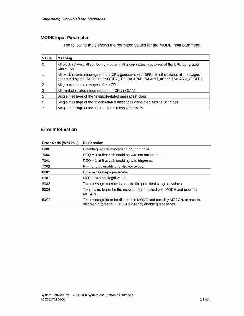
Generating Block-Related Messages
System Software for S7-300/400 System and Standard FunctionsA5E00171234-01 21-23
MODE Input Parameter
The following table shows the permitted values for the MODE input parameter.
Value Meaning
0 All block-related, all symbol-related and all group status messages of the CPU generatedwith SFBs
1 All block-related messages of the CPU generated with SFBs, in other words all messagesgenerated by the "NOTIFY", "NOTIFY_8P", "ALARM", "ALARM_8P" and "ALARM_8" SFBs
2 All group status messages of the CPU
3 All symbol-related messages of the CPU (SCAN)
5 Single message of the "symbol-related messages" class
6 Single message of the "block-related messages generated with SFBs" class
7 Single message of the "group status messages" class
Error Information
Error Code (W#16#...) Explanation
0000 Disabling was terminated without an error.
7000 REQ = 0 at first call: enabling was not activated.
7001 REQ = 1 at first call: enabling was triggered.
7002 Further call: enabling is already active.
8081 Error accessing a parameter
8082 MODE has an illegal value.
8083 The message number is outside the permitted range of values.
8084 There is no logon for the message(s) specified with MODE and possiblyMESGN.
80C3 The message(s) to be disabled in MODE and possibly MESGN, cannot bedisabled at present - SFC 9 is already enabling messages.
Generating Block-Related Messages
System Software for S7-300/400 System and Standard Functions21-24 A5E00171234-01
21.10 Startup Behavior of the SFBs for Generating Block-Related Messages
Restart (Warm Restart)
During a warm restart, the instance DBs of the SFBs for generating block-relatedmessages are set to the not initialized NO_INIT status. The actual parametersstored in the instance DBs are unchanged. The parameter ID and EV_ID will beevaluated at the next block call.
Complete Restart
During a complete restart the contents of the instance DBs of the SFBs forgenerating block-related messages are reset to their initial values.
Hot Restart
During a hot restart, the SFBs for generating block-related messages behave likeuser function blocks that are capable of resuming execution. They continue fromthe point of interruption.
Memory Reset
A memory reset always causes the termination of all connections so that no stationis logged on for messages. The user program is deleted. If you have inserted aFLASH card, the program sections relevant to execution are loaded on the CPUagain from the card and the CPU executes a warm or cold restart (implicitly this isalways a cold restart, since all user data are initialized after clearing memory).
21.11 How the SFBs for Generating Block-Related MessagesReact to Problems
Connection Breakdown
The connections assigned to the SFB instances are monitored for breakdown. If aconnection breaks down, the stations involved are removed from the internal CPUlist of stations logged on for block-related messages. Any messages pending forthese stations are deleted.
If other stations are still logged on following a connection breakdown, they continueto receive messages. The SFBs only stop sending messages when there are nomore connections to any logged on stations. The ERROR and STATUS outputparameters indicate this situation (ERROR = 1, STATUS = 1).
Generating Block-Related Messages
System Software for S7-300/400 System and Standard FunctionsA5E00171234-01 21-25
Error Interface to the User Program
If an error occurs during the execution of an SFB for generating block-relatedmessages, the ERROR output parameter is set to 1 and the STATUS outputparameter has the corresponding error identifier. You can evaluate this errorinformation in your program.
Examples of possible errors:
• Sending not possible due to lack of resources
• Error accessing one of the signals to be monitored.
21.12 Introduction to Generating Block-Related Messages withSFCs
SFCs for Generating Block-Related Messages
You can generate a block-related message with the following SFCs:
• SFC 17 "ALARM_SQ"
• SFC 18 "ALARM_S"
• SFC 107 "ALARM_DQ"
• SFC 108 "ALARM_D"
These SFCs have the following properties:
• The messages sent by SFC 17 "ALARM_SQ" and SFC 107 "ALARM_DQ"when the signal state is 1 can be acknowledged at a logged on display device.The messages of SFC 18 "ALARM_S" and SFC 108 "ALARM_D" are alwaysimplicitly acknowledged. It is not a detected edge change that generates amessage but rather each SFC call. For more detailed information refer toGenerating Acknowledgeable Block-Related Messages with SFC 17"ALARM_SQ" and Permanently Acknowledged Block-Related Messages withSFC 18 "ALARM_S
• "ALARM_S" and the section Generating Acknowledgeable Block-RelatedMessages with the SFCs 17 "ALARM_DQ" and 108 "ALARM_D".
• Following execution of the block, the associated value SD_1 is read completelyand assigned to the message. In terms of consistency compared with high-priority classes, the following associated values are consistent:
- the simple data types (bit, byte, word, and double word)
- an array of the data type byte up to a maximum length specific to theparticular CPU (see /71/, /101/).
Generating Block-Related Messages
System Software for S7-300/400 System and Standard Functions21-26 A5E00171234-01
SFC 19 "ALARM_SC"
Using SFC 19 "ALARM_SC" you can query the following:
• The acknowledgment status of the last "entering state message" and the signalstate at the last SFC 17/SFC 107 call, or
• The signal state at the last SFC 18/SFC 108 call.
Logging On Display Devices
The SFCs for generating block-related messages only send a message when theyare called if at least one display device has logged on for block-related messages.
Message Storage
To avoid messages being lost when there is a lot of traffic on the communicationssystem, the SFCs 17, 18, 107 and 108 can both buffer two messages.If, however, messages are lost, you are informed in RET_VAL. The logged ondisplay devices are informed of this the next time a message can be sent.
Message Acknowledgment with the SFCs 17 "ALARM_SQ" and 107"ALARM_DQ"
If you have acknowledged an "entering event message" at a display device, thisacknowledgment information is first sent to the CPU where the messageoriginated. This then distributes the acknowledgment information to all stationslogged on for this purpose.
Disabling and Enabling Messages
Block-related messages generated with SFC 17 "ALARM_SQ", SFC 18"ALARM_S", SFC 107 "ALARM_DQ" or SFC 108 "ALARM_D" cannot be disabledand then enabled again.
Changes in Your Program that contains the SFC 17/SFC 18 calls
Note
When you download a block that is already on the CPU using SFC 17/SFC 18calls, it is possible that the previous block has sent an entering state message butthat the new block does not send a corresponding leaving state message. Thismeans that the message remains in the internal message memory of the CPU.This situation can also occur when you delete blocks with SFC 17/SFC 18.You can remove such messages from the internal message memory of the CPU bychanging the CPU to STOP and then going through a warm or cold restart.
Generating Block-Related Messages
System Software for S7-300/400 System and Standard FunctionsA5E00171234-01 21-27
Changes in Your Program that contains the SFC 17/SFC 18 calls
Even though your program might contain SFC 107 and/or SFC 108 calls, thedescribed program modifications may cause the messages to become resident inthe internal message memory and thus permanently occupy system resources.
Contrary to system resources which were occupied by SFC 17/SFC 18 calls, youcan release system resources occupied by SFC 107/SFC 108 calls without havingto switch your CPU to STOP mode. This is carried out by using SFC 106 "DEL_SI",see Releasing Dynamically Occupied System Resources with SFC 106 "DEL_SI" .Before you release dynamically occupied system resources by calling SFC 106"DEL_SI", it may be appropriate to fetch information on currently dynamicallyoccupied system resources of your CPU, with the help of SFC 105 "READ_SI", seeReading Dynamically Occupied System Resources with SFC 105 "READ_SI".
Amount of transferable data
The amount of data transferable using the accompanying value SD for SFCsALARM_S, ALARM_SQ, ALARM_D and ALARM_DQ cannot exceed a maximumlength. This data length is calculated as follows:
maxleng = min (pdu_local, pdu_remote) - 48
Definitions:
• pdu_local: the maximum length for CPU data blocks (SZL_ID W#16#0131,INDEX 1, Variable pdu)
• pdu_remote: the maximum length for display device data blocks
Example:
A CPU 414-1 sends a message to a programming device PG 760 (via MPI).
pdu_local = 480 Byte, pdu_remote = 480 bytes,
Result:
maxleng = min (480, 480) - 48 = 480 - 48 = 432
The maximum transferable data length per SFC is thus 432 bytes.
Generating Block-Related Messages
System Software for S7-300/400 System and Standard Functions21-28 A5E00171234-01
21.13 Generating Acknowledgeable Block-Related Messageswith SFC 17 "ALARM_SQ" and PermanentlyAcknowledged Block-Related Messages with SFC 18"ALARM_S"
Note
Newly created programs should only use SFCs 107 and 108 since they provideimproved options for managing system resources.
Description
Each time they are called, SFC 17 "ALARM_SQ" and SFC 18 "ALARM_S"generate a message to which you can add associated values. The message is sentto all stations that have logged on for the message. SFC 17 and SFC 18 provideyou with a simple mechanism for sending messages. You must make sure that youonly call SFC 17 or SFC 18 when the value of the triggering signal SIG is invertedcompared with the last call. If this is not the case, this is indicated in RET_VAL andno message is sent. The very first time that SFC 17 or SFC 18 is called, you mustmake sure that the SIG input has the value 1. Otherwise, RET_VAL contains errorinformation and no message will be sent.
Note
Call SFC 17 and SFC 18 in an FB to which you have previously assigned suitablesystem attributes! For more detailed information about assigning system attributesto blocks, refer to /232/ and /233/.
Use of system resources
When generating messages with the SFCs 17 "ALARM_SQ" and 18 "ALARM_S",the operating system uses one system resource for the duration of the signal cycle.
For SFC 18 "ALARM_S", the signal cycle lasts from the SFC call SIG=1 untilanother call with SIG=0. For SFC 17 "ALARM_SQ", this time period also includesthe time until the incoming signal is acknowledged by one of the reported displaydevices, if necessary.
If, during the signal cycle, the message-generating block is overloaded or deleted,the associated system resource remains occupied until the next restart (warmrestart).
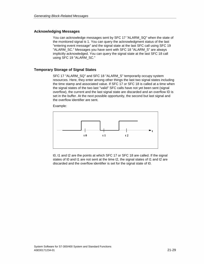
Generating Block-Related Messages
System Software for S7-300/400 System and Standard FunctionsA5E00171234-01 21-29
Acknowledging Messages
You can acknowledge messages sent by SFC 17 "ALARM_SQ" when the state ofthe monitored signal is 1. You can query the acknowledgment status of the last"entering event message" and the signal state at the last SFC call using SFC 19"ALARM_SC." Messages you have sent with SFC 18 "ALARM_S" are alwaysimplicitly acknowledged. You can query the signal state at the last SFC 18 callusing SFC 19 "ALARM_SC."
Temporary Storage of Signal States
SFC 17 "ALARM_SQ" and SFC 18 "ALARM_S" temporarily occupy systemresources. Here, they enter among other things the last two signal states includingthe time stamp and associated value. If SFC 17 or SFC 18 is called at a time whenthe signal states of the two last "valid" SFC calls have not yet been sent (signaloverflow), the current and the last signal state are discarded and an overflow ID isset in the buffer. At the next possible opportunity, the second but last signal andthe overflow identifier are sent.
Example:
t
t 1 t 2t 0
t0, t1 and t2 are the points at which SFC 17 or SFC 18 are called. If the signalstates of t0 and t1 are not sent at the time t2, the signal states of t1 and t2 arediscarded and the overflow identifier is set for the signal state of t0.
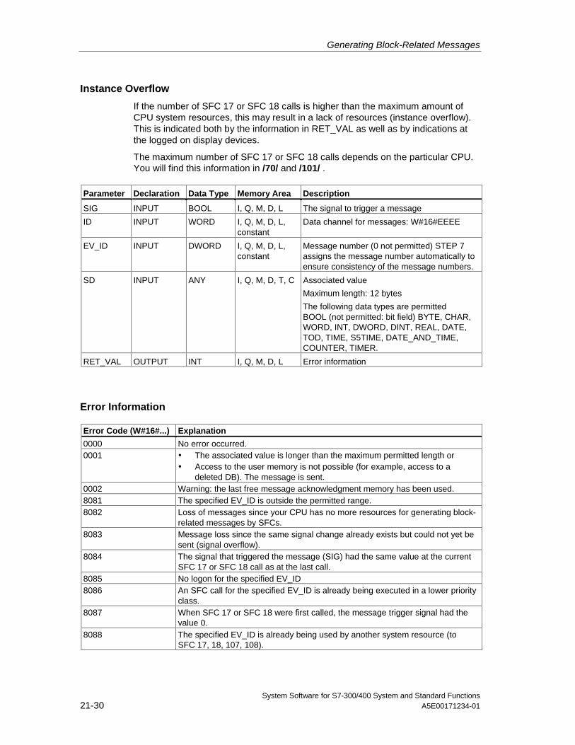
Generating Block-Related Messages
System Software for S7-300/400 System and Standard Functions21-30 A5E00171234-01
Instance Overflow
If the number of SFC 17 or SFC 18 calls is higher than the maximum amount ofCPU system resources, this may result in a lack of resources (instance overflow).This is indicated both by the information in RET_VAL as well as by indications atthe logged on display devices.
The maximum number of SFC 17 or SFC 18 calls depends on the particular CPU.You will find this information in /70/ and /101/ .
Parameter Declaration Data Type Memory Area Description
SIG INPUT BOOL I, Q, M, D, L The signal to trigger a message
ID INPUT WORD I, Q, M, D, L,constant
Data channel for messages: W#16#EEEE
EV_ID INPUT DWORD I, Q, M, D, L,constant
Message number (0 not permitted) STEP 7assigns the message number automatically toensure consistency of the message numbers.
SD INPUT ANY I, Q, M, D, T, C Associated value
Maximum length: 12 bytes
The following data types are permittedBOOL (not permitted: bit field) BYTE, CHAR,WORD, INT, DWORD, DINT, REAL, DATE,TOD, TIME, S5TIME, DATE_AND_TIME,COUNTER, TIMER.
RET_VAL OUTPUT INT I, Q, M, D, L Error information
Error Information
Error Code (W#16#...) Explanation
0000 No error occurred.0001 • The associated value is longer than the maximum permitted length or
• Access to the user memory is not possible (for example, access to adeleted DB). The message is sent.
0002 Warning: the last free message acknowledgment memory has been used.8081 The specified EV_ID is outside the permitted range.8082 Loss of messages since your CPU has no more resources for generating block-
related messages by SFCs.8083 Message loss since the same signal change already exists but could not yet be
sent (signal overflow).8084 The signal that triggered the message (SIG) had the same value at the current
SFC 17 or SFC 18 call as at the last call.8085 No logon for the specified EV_ID8086 An SFC call for the specified EV_ID is already being executed in a lower priority
class.8087 When SFC 17 or SFC 18 were first called, the message trigger signal had the
value 0.8088 The specified EV_ID is already being used by another system resource (to
SFC 17, 18, 107, 108).
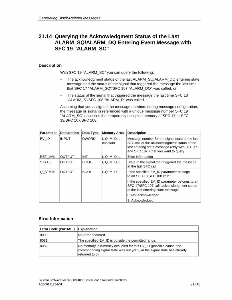
Generating Block-Related Messages
System Software for S7-300/400 System and Standard FunctionsA5E00171234-01 21-31
21.14 Querying the Acknowledgment Status of the LastALARM_SQ/ALARM_DQ Entering Event Message withSFC 19 "ALARM_SC"
Description
With SFC 19 "ALARM_SC" you can query the following:
• The acknowledgment status of the last ALARM_SQ/ALARM_DQ entering statemessage and the status of the signal that triggered the message the last timethat SFC 17 "ALARM_SQ"/SFC 107 "ALARM_DQ" was called, or
• The status of the signal that triggered the message the last time SFC 18"ALARM_S"/SFC 108 "ALARM_D" was called.
Assuming that you assigned the message numbers during message configuration,the message or signal is referenced with a unique message number SFC 19"ALARM_SC" accesses the temporarily occupied memory of SFC 17 or SFC18/SFC 107/SFC 108.
Parameter Declaration Data Type Memory Area Description
EV_ID INPUT DWORD I, Q, M, D, L,constant
Message number for the signal state at the lastSFC call or the acknowledgment status of thelast entering state message (only with SFC 17and SFC 107!) that you want to query.
RET_VAL OUTPUT INT I, Q, M, D, L Error information
STATE OUTPUT BOOL I, Q, M, D, L State of the signal that triggered the messageat the last SFC call
Q_STATE OUTPUT BOOL I, Q, M, D, L If the specified EV_ID parameter belongsto an SFC 18/SFC 108 call: 1
If the specified EV_ID parameter belongs to anSFC 17/SFC 107 call: acknowledgment statusof the last entering state message:
0: Not acknowledged
1: Acknowledged
Error Information
Error Code (W#16#...) Explanation
0000 No error occurred.
8081 The specified EV_ID is outside the permitted range.
8082 No memory is currently occupied for this EV_ID (possible cause: thecorresponding signal state was not yet 1, or the signal state has alreadyreturned to 0).
Generating Block-Related Messages
System Software for S7-300/400 System and Standard Functions21-32 A5E00171234-01
21.15 Generating Acknowledgeable and PermanentlyAcknowledged Block Related Messages with SFCs 107"ALARM_DQ" and 108 "ALARM_D"
Description
With every call the SFCs 107 "ALARM_DQ" and 108 "ALARM_D" generate amessage to which you can append an associated value. Thus, you correspond withSFCs 17 "ALARM_SQ" and 18 "ALARM_S".
When generating messages with SFCs 107 "ALARM_DQ" and 108 "ALARM_D",the operating system temporarily occupies a system resource for the duration ofthe signal cycle.
The signal cycle time for SFC 108 "ALARM_D" starts at the SFC call with SIG=1and ends at a new call with SIG=0. This interval for SFC 107 "ALARM_DQ" may beextended by the time expiring until the incoming signal is acknowledged at alogged in displaying device.
For SFC 108 "ALARM_D", the signal cycle lasts from the SFC call SIG=1 untilanother call with SIG=0. For SFC 107 "ALARM_DQ", this time period also includesthe time until the incoming signal is acknowledged by one of the reported displaydevices, if necessary.
If, during the signal cycle, the message-generating block is overloaded or deleted,the associated system resource remains occupied until the next restart (warmrestart).
The additional functionality of SFCs 107 "ALARM_DQ" and 108 "ALARM_D"compared to SFCs 17 and 18 is now that you can manage these occupied systemresources:
• With the help of SFC 105 "READ_SI" you can fetch information related tooccupied system resources.
• With SFC 106 "DEL_SI" you can release occupied system resources again.This is of special significance for permanently occupied system resources. Acurrently occupied system resource, for example, stays occupied until the nextrestart (warm restart) if you, in the course of a program change, delete an FBcall that contains SFC107 or SFC108 calls . When you change the program,and reload an FB with SFC 107 or SFC 108 calls, it may happen that the SFCs107 and 108 do not generate anymore messages.
The SFCs 107 and 108 contain one parameter more than the SFCs 17 and 18,namely the input CMP_ID. Use this input to assign the messages generated withSFCs 107 and 108 to logical areas, for example to parts of the system. If you callSFC 107/SFC 108 in an FB the obvious thing to do is to assign the number of thecorresponding instance DB to CMP_ID.
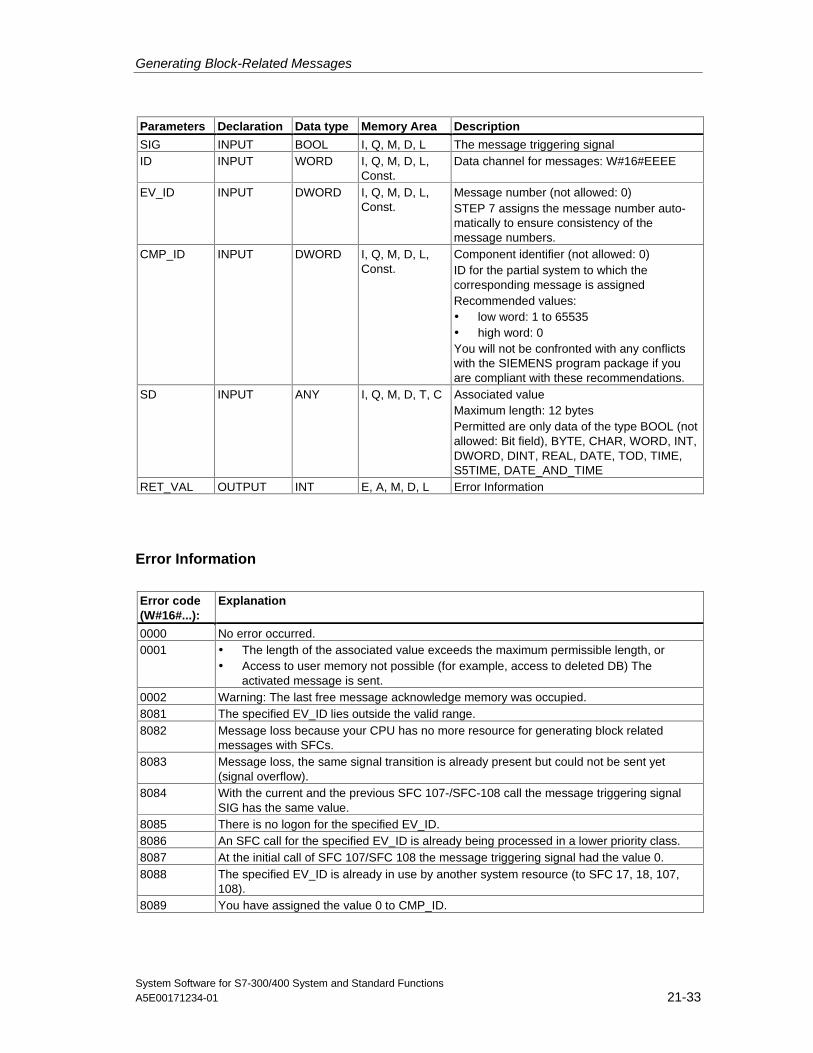
Generating Block-Related Messages
System Software for S7-300/400 System and Standard FunctionsA5E00171234-01 21-33
Parameters Declaration Data type Memory Area Description
SIG INPUT BOOL I, Q, M, D, L The message triggering signalID INPUT WORD I, Q, M, D, L,
Const.Data channel for messages: W#16#EEEE
EV_ID INPUT DWORD I, Q, M, D, L,Const.
Message number (not allowed: 0)STEP 7 assigns the message number auto-matically to ensure consistency of themessage numbers.
CMP_ID INPUT DWORD I, Q, M, D, L,Const.
Component identifier (not allowed: 0)ID for the partial system to which thecorresponding message is assignedRecommended values:• low word: 1 to 65535• high word: 0You will not be confronted with any conflictswith the SIEMENS program package if youare compliant with these recommendations.
SD INPUT ANY I, Q, M, D, T, C Associated valueMaximum length: 12 bytesPermitted are only data of the type BOOL (notallowed: Bit field), BYTE, CHAR, WORD, INT,DWORD, DINT, REAL, DATE, TOD, TIME,S5TIME, DATE_AND_TIME
RET_VAL OUTPUT INT E, A, M, D, L Error Information
Error Information
Error code(W#16#...):
Explanation
0000 No error occurred.0001 • The length of the associated value exceeds the maximum permissible length, or
• Access to user memory not possible (for example, access to deleted DB) Theactivated message is sent.
0002 Warning: The last free message acknowledge memory was occupied.8081 The specified EV_ID lies outside the valid range.8082 Message loss because your CPU has no more resource for generating block related
messages with SFCs.8083 Message loss, the same signal transition is already present but could not be sent yet
(signal overflow).8084 With the current and the previous SFC 107-/SFC-108 call the message triggering signal
SIG has the same value.8085 There is no logon for the specified EV_ID.8086 An SFC call for the specified EV_ID is already being processed in a lower priority class.8087 At the initial call of SFC 107/SFC 108 the message triggering signal had the value 0.8088 The specified EV_ID is already in use by another system resource (to SFC 17, 18, 107,
108).8089 You have assigned the value 0 to CMP_ID.
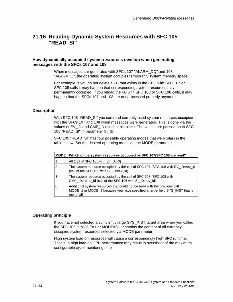
Generating Block-Related Messages
System Software for S7-300/400 System and Standard Functions21-34 A5E00171234-01
21.16 Reading Dynamic System Resources with SFC 105"READ_SI"
How dynamically occupied system resources develop when generatingmessages with the SFCs 107 and 108
When messages are generated with SFCs 107 "ALARM_DQ" and 108"ALARM_D", the operating system occupies temporarily system memory space.
For example, if you do not delete a FB that exists in the CPU with SFC 107 orSFC 108 calls it may happen that corresponding system resources staypermanently occupied. If you reload the FB with SFC 108 or SFC 108 calls, it mayhappen that the SFCs 107 and 108 are not processed properly anymore.
Description
With SFC 105 "READ_SI" you can read currently used system resources occupiedwith the SFCs 107 and 108 when messages were generated. This is done via thevalues of EV_ID and CMP_ID used in this place. The values are passed on to SFC105 "READ_SI" in parameter SI_ID.
SFC 105 "READ_SI" has four possible operating modes that we explain in thetable below. Set the desired operating mode via the MODE parameter.
MODE Which of the system resources occupied by SFC 107/SFC 108 are read?
1 All (call of SFC 105 with SI_ID:=0)
2 The system resource occupied by the call of SFC 107-/SFC 108 with EV_ID:=ev_id(call of the SFC 105 with SI_ID:=ev_id)
3 The system resource occupied by the call of SFC 107-/SFC 108 withCMP_ID:=cmp_id (call of the SFC 105 with SI_ID:=ev_id)
0 Additional system resources that could not be read with the previous call inMODE=1 or MODE=3 because you have specified a target field SYS_INST that istoo small
Operating principle
If you have not selected a sufficiently large SYS_INST target area when you calledthe SFC 105 in MODE=1 or MODE=3, it contains the content of all currentlyoccupied system resources selected via MODE parameter.
High system load on resources will cause a correspondingly high SFC runtime.That is, a high load on CPU performance may result in overshoot of the maximumconfigurable cycle monitoring time.
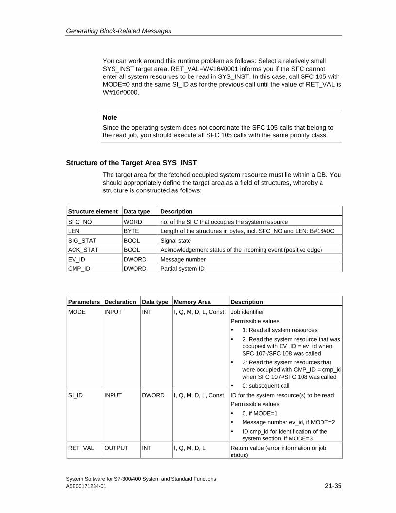
Generating Block-Related Messages
System Software for S7-300/400 System and Standard FunctionsA5E00171234-01 21-35
You can work around this runtime problem as follows: Select a relatively smallSYS_INST target area. RET_VAL=W#16#0001 informs you if the SFC cannotenter all system resources to be read in SYS_INST. In this case, call SFC 105 withMODE=0 and the same SI_ID as for the previous call until the value of RET_VAL isW#16#0000.
Note
Since the operating system does not coordinate the SFC 105 calls that belong tothe read job, you should execute all SFC 105 calls with the same priority class.
Structure of the Target Area SYS_INST
The target area for the fetched occupied system resource must lie within a DB. Youshould appropriately define the target area as a field of structures, whereby astructure is constructed as follows:
Structure element Data type Description
SFC_NO WORD no. of the SFC that occupies the system resource
LEN BYTE Length of the structures in bytes, incl. SFC_NO and LEN: B#16#0C
SIG_STAT BOOL Signal state
ACK_STAT BOOL Acknowledgement status of the incoming event (positive edge)
EV_ID DWORD Message number
CMP_ID DWORD Partial system ID
Parameters Declaration Data type Memory Area Description
MODE INPUT INT I, Q, M, D, L, Const. Job identifier
Permissible values
• 1: Read all system resources
• 2. Read the system resource that wasoccupied with EV_ID = ev_id whenSFC 107-/SFC 108 was called
• 3: Read the system resources thatwere occupied with CMP_ID = cmp_idwhen SFC 107-/SFC 108 was called
• 0: subsequent call
SI_ID INPUT DWORD I, Q, M, D, L, Const. ID for the system resource(s) to be read
Permissible values
• 0, if MODE=1
• Message number ev_id, if MODE=2
• ID cmp_id for identification of thesystem section, if MODE=3
RET_VAL OUTPUT INT I, Q, M, D, L Return value (error information or jobstatus)
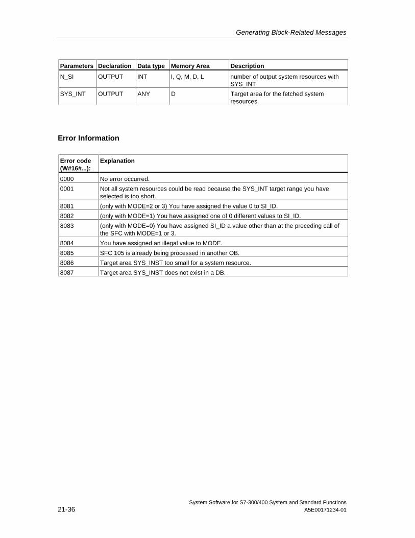
Generating Block-Related Messages
System Software for S7-300/400 System and Standard Functions21-36 A5E00171234-01
Parameters Declaration Data type Memory Area Description
N_SI OUTPUT INT I, Q, M, D, L number of output system resources withSYS_INT
SYS_INT OUTPUT ANY D Target area for the fetched systemresources.
Error Information
Error code(W#16#...):
Explanation
0000 No error occurred.
0001 Not all system resources could be read because the SYS_INT target range you haveselected is too short.
8081 (only with MODE=2 or 3) You have assigned the value 0 to SI_ID.
8082 (only with MODE=1) You have assigned one of 0 different values to SI_ID.
8083 (only with MODE=0) You have assigned SI_ID a value other than at the preceding call ofthe SFC with MODE=1 or 3.
8084 You have assigned an illegal value to MODE.
8085 SFC 105 is already being processed in another OB.
8086 Target area SYS_INST too small for a system resource.
8087 Target area SYS_INST does not exist in a DB.
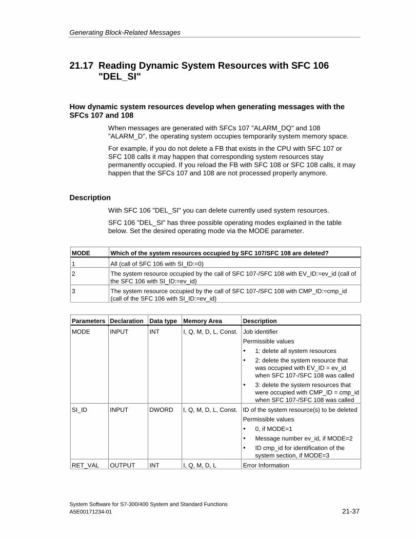
Generating Block-Related Messages
System Software for S7-300/400 System and Standard FunctionsA5E00171234-01 21-37
21.17 Reading Dynamic System Resources with SFC 106"DEL_SI"
How dynamic system resources develop when generating messages with theSFCs 107 and 108
When messages are generated with SFCs 107 "ALARM_DQ" and 108"ALARM_D", the operating system occupies temporarily system memory space.
For example, if you do not delete a FB that exists in the CPU with SFC 107 orSFC 108 calls it may happen that corresponding system resources staypermanently occupied. If you reload the FB with SFC 108 or SFC 108 calls, it mayhappen that the SFCs 107 and 108 are not processed properly anymore.
Description
With SFC 106 "DEL_SI" you can delete currently used system resources.
SFC 106 "DEL_SI" has three possible operating modes explained in the tablebelow. Set the desired operating mode via the MODE parameter.
MODE Which of the system resources occupied by SFC 107/SFC 108 are deleted?
1 All (call of SFC 106 with SI_ID:=0)
2 The system resource occupied by the call of SFC 107-/SFC 108 with EV_ID:=ev_id (call ofthe SFC 106 with SI_ID:=ev_id)
3 The system resource occupied by the call of SFC 107-/SFC 108 with CMP_ID:=cmp_id(call of the SFC 106 with SI_ID:=ev_id)
Parameters Declaration Data type Memory Area Description
MODE INPUT INT I, Q, M, D, L, Const. Job identifier
Permissible values
• 1: delete all system resources
• 2: delete the system resource thatwas occupied with EV_ID = ev_idwhen SFC 107-/SFC 108 was called
• 3: delete the system resources thatwere occupied with CMP_ID = cmp_idwhen SFC 107-/SFC 108 was called
SI_ID INPUT DWORD I, Q, M, D, L, Const. ID of the system resource(s) to be deleted
Permissible values
• 0, if MODE=1
• Message number ev_id, if MODE=2
• ID cmp_id for identification of thesystem section, if MODE=3
RET_VAL OUTPUT INT I, Q, M, D, L Error Information
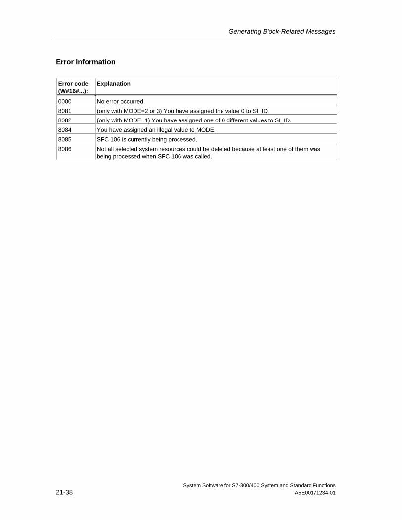
Generating Block-Related Messages
System Software for S7-300/400 System and Standard Functions21-38 A5E00171234-01
Error Information
Error code(W#16#...):
Explanation
0000 No error occurred.
8081 (only with MODE=2 or 3) You have assigned the value 0 to SI_ID.
8082 (only with MODE=1) You have assigned one of 0 different values to SI_ID.
8084 You have assigned an illegal value to MODE.
8085 SFC 106 is currently being processed.
8086 Not all selected system resources could be deleted because at least one of them wasbeing processed when SFC 106 was called.
System Software for S7-300/400 System and Standard FunctionsA5E00171234-01 22-1
22 IEC Timers and IEC Counters
22.1 Generating a Pulse with SFB 3 "TP"
Description
SFB 3 "TP" generates a pulse with the length PT. The timer runs only in theSTARTUP and RUN modes.
A rising signal edge at input IN starts the pulse. Output Q remains set for the timePT regardless of changes in the input signal (in other words even when the INinput changes back from 0 to 1 before the time PT has expired).The ET outputprovides the time for which output Q has already been set. The maximum value ofthe ET output is the value of the PT input. Output ET is reset when input INchanges to 0, however, not before the time PT has expired.
SFB 3 "TP" complies with the IEC 1131-3 standard.
The operating system resets the instances of SFB 3 "TP" during a cold restart. Ifyou want instances of this SFB to be initialized following a warm restart, you mustcall SFB 3 with PT = 0 ms in OB100. If instances of this SFB are located withinanother block, you can reset these instances, for example, by initializing thehigher-level block.
Timing Diagram
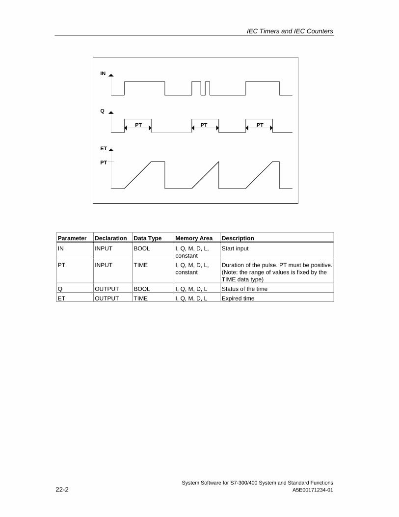
IEC Timers and IEC Counters
System Software for S7-300/400 System and Standard Functions22-2 A5E00171234-01
PT
ET
Q
IN
PT
PTPT
Parameter Declaration Data Type Memory Area Description
IN INPUT BOOL I, Q, M, D, L,constant
Start input
PT INPUT TIME I, Q, M, D, L,constant
Duration of the pulse. PT must be positive.(Note: the range of values is fixed by theTIME data type)
Q OUTPUT BOOL I, Q, M, D, L Status of the time
ET OUTPUT TIME I, Q, M, D, L Expired time
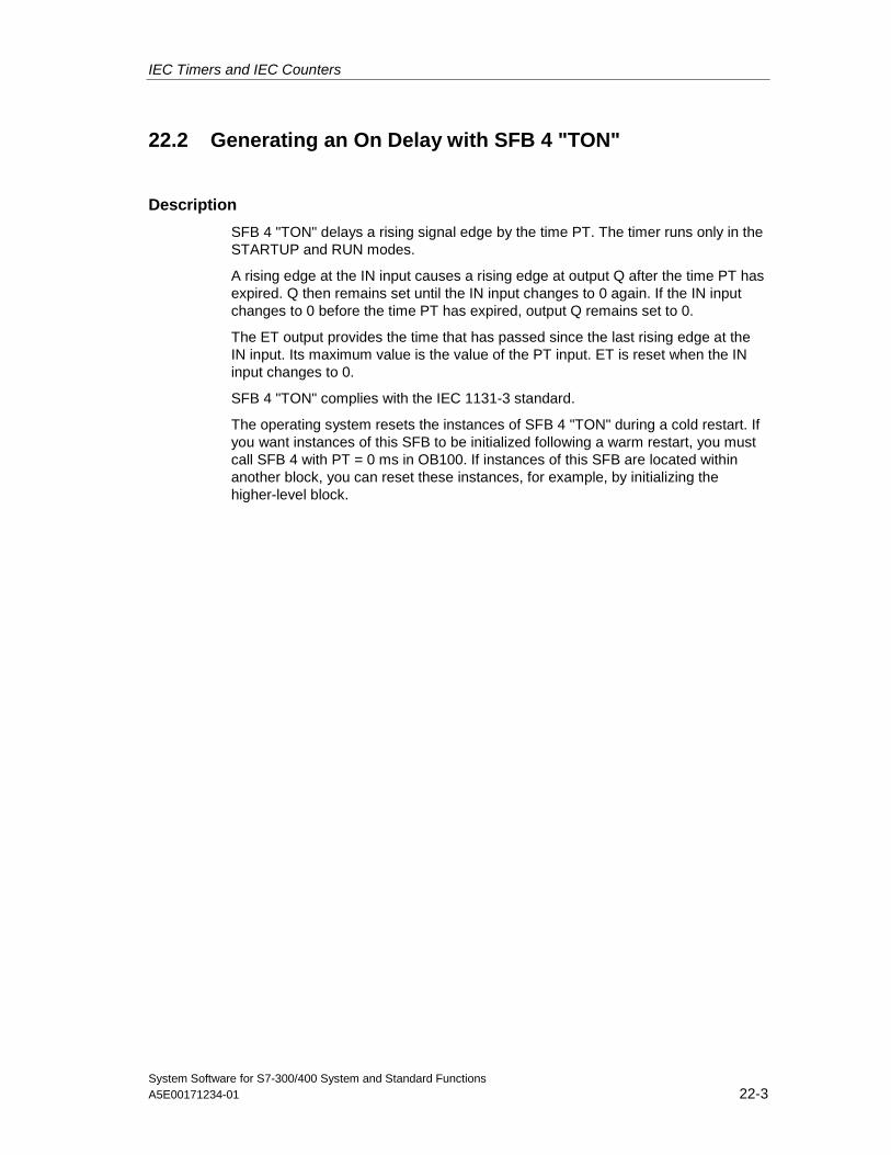
IEC Timers and IEC Counters
System Software for S7-300/400 System and Standard FunctionsA5E00171234-01 22-3
22.2 Generating an On Delay with SFB 4 "TON"
Description
SFB 4 "TON" delays a rising signal edge by the time PT. The timer runs only in theSTARTUP and RUN modes.
A rising edge at the IN input causes a rising edge at output Q after the time PT hasexpired. Q then remains set until the IN input changes to 0 again. If the IN inputchanges to 0 before the time PT has expired, output Q remains set to 0.
The ET output provides the time that has passed since the last rising edge at theIN input. Its maximum value is the value of the PT input. ET is reset when the INinput changes to 0.
SFB 4 "TON" complies with the IEC 1131-3 standard.
The operating system resets the instances of SFB 4 "TON" during a cold restart. Ifyou want instances of this SFB to be initialized following a warm restart, you mustcall SFB 4 with PT = 0 ms in OB100. If instances of this SFB are located withinanother block, you can reset these instances, for example, by initializing thehigher-level block.
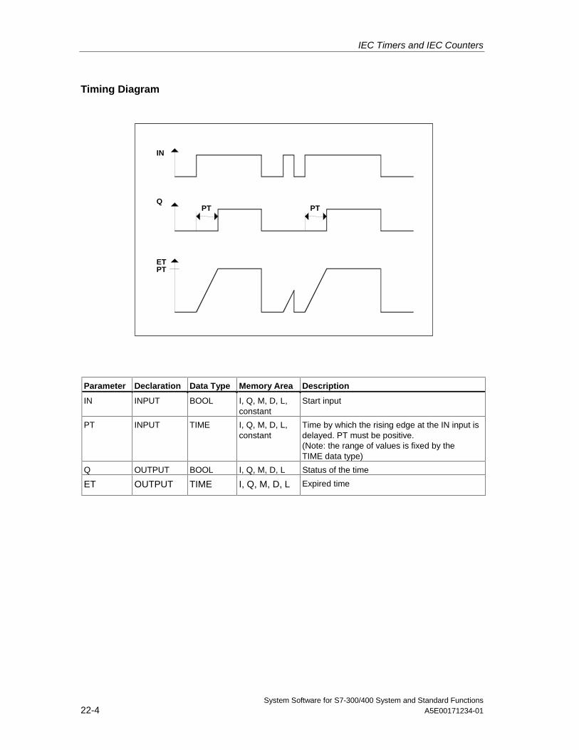
IEC Timers and IEC Counters
System Software for S7-300/400 System and Standard Functions22-4 A5E00171234-01
Timing Diagram
ET
Q
IN
PT
PT PT
Parameter Declaration Data Type Memory Area Description
IN INPUT BOOL I, Q, M, D, L,constant
Start input
PT INPUT TIME I, Q, M, D, L,constant
Time by which the rising edge at the IN input isdelayed. PT must be positive.(Note: the range of values is fixed by theTIME data type)
Q OUTPUT BOOL I, Q, M, D, L Status of the time
ET OUTPUT TIME I, Q, M, D, L Expired time
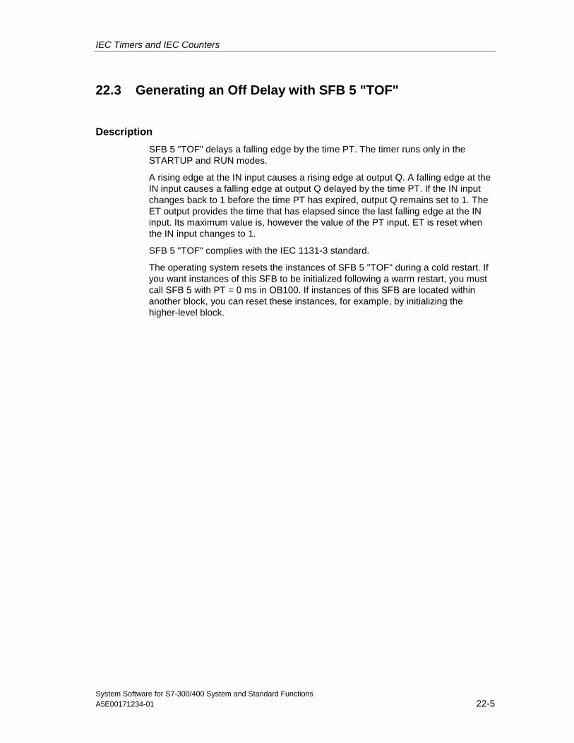
IEC Timers and IEC Counters
System Software for S7-300/400 System and Standard FunctionsA5E00171234-01 22-5
22.3 Generating an Off Delay with SFB 5 "TOF"
Description
SFB 5 "TOF" delays a falling edge by the time PT. The timer runs only in theSTARTUP and RUN modes.
A rising edge at the IN input causes a rising edge at output Q. A falling edge at theIN input causes a falling edge at output Q delayed by the time PT. If the IN inputchanges back to 1 before the time PT has expired, output Q remains set to 1. TheET output provides the time that has elapsed since the last falling edge at the INinput. Its maximum value is, however the value of the PT input. ET is reset whenthe IN input changes to 1.
SFB 5 "TOF" complies with the IEC 1131-3 standard.
The operating system resets the instances of SFB 5 "TOF" during a cold restart. Ifyou want instances of this SFB to be initialized following a warm restart, you mustcall SFB 5 with PT = 0 ms in OB100. If instances of this SFB are located withinanother block, you can reset these instances, for example, by initializing thehigher-level block.
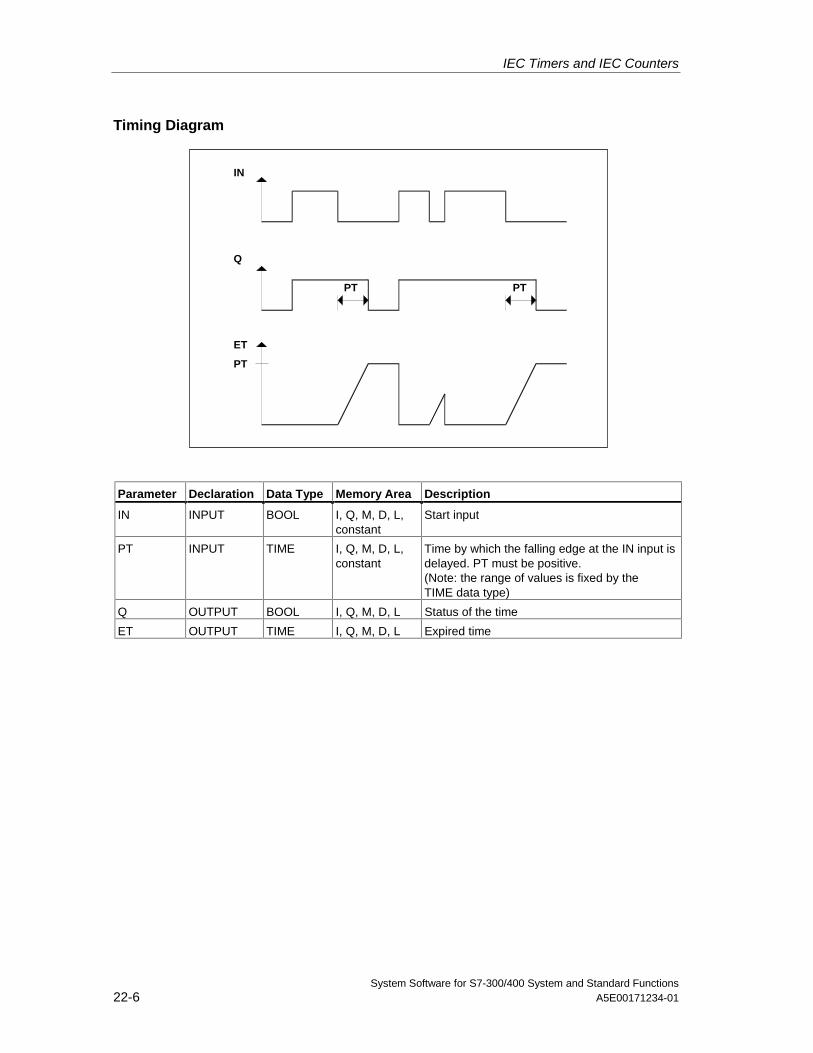
IEC Timers and IEC Counters
System Software for S7-300/400 System and Standard Functions22-6 A5E00171234-01
Timing Diagram
PT PT
ET
Q
IN
PT
Parameter Declaration Data Type Memory Area Description
IN INPUT BOOL I, Q, M, D, L,constant
Start input
PT INPUT TIME I, Q, M, D, L,constant
Time by which the falling edge at the IN input isdelayed. PT must be positive.(Note: the range of values is fixed by theTIME data type)
Q OUTPUT BOOL I, Q, M, D, L Status of the time
ET OUTPUT TIME I, Q, M, D, L Expired time
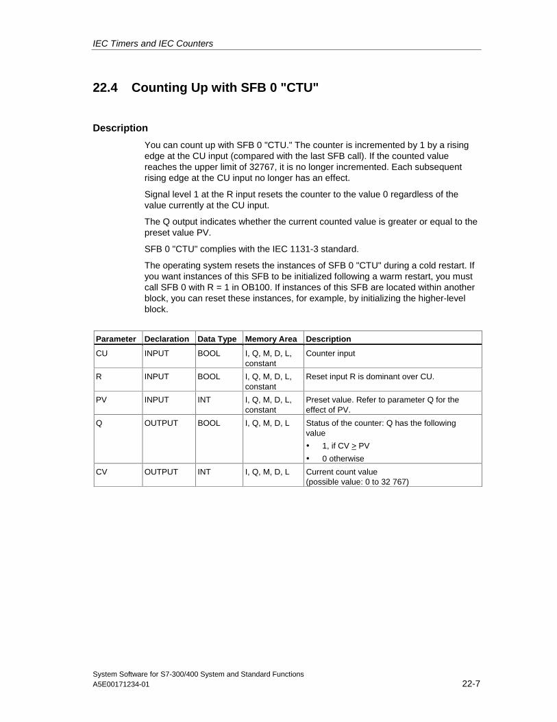
IEC Timers and IEC Counters
System Software for S7-300/400 System and Standard FunctionsA5E00171234-01 22-7
22.4 Counting Up with SFB 0 "CTU"
Description
You can count up with SFB 0 "CTU." The counter is incremented by 1 by a risingedge at the CU input (compared with the last SFB call). If the counted valuereaches the upper limit of 32767, it is no longer incremented. Each subsequentrising edge at the CU input no longer has an effect.
Signal level 1 at the R input resets the counter to the value 0 regardless of thevalue currently at the CU input.
The Q output indicates whether the current counted value is greater or equal to thepreset value PV.
SFB 0 "CTU" complies with the IEC 1131-3 standard.
The operating system resets the instances of SFB 0 "CTU" during a cold restart. Ifyou want instances of this SFB to be initialized following a warm restart, you mustcall SFB 0 with R = 1 in OB100. If instances of this SFB are located within anotherblock, you can reset these instances, for example, by initializing the higher-levelblock.
Parameter Declaration Data Type Memory Area Description
CU INPUT BOOL I, Q, M, D, L,constant
Counter input
R INPUT BOOL I, Q, M, D, L,constant
Reset input R is dominant over CU.
PV INPUT INT I, Q, M, D, L,constant
Preset value. Refer to parameter Q for theeffect of PV.
Q OUTPUT BOOL I, Q, M, D, L Status of the counter: Q has the followingvalue
• 1, if CV > PV
• 0 otherwise
CV OUTPUT INT I, Q, M, D, L Current count value(possible value: 0 to 32 767)
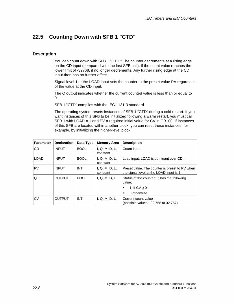
IEC Timers and IEC Counters
System Software for S7-300/400 System and Standard Functions22-8 A5E00171234-01
22.5 Counting Down with SFB 1 "CTD"
Description
You can count down with SFB 1 "CTD." The counter decrements at a rising edgeon the CD input (compared with the last SFB call). If the count value reaches thelower limit of -32768, it no longer decrements. Any further rising edge at the CDinput then has no further effect.
Signal level 1 at the LOAD input sets the counter to the preset value PV regardlessof the value at the CD input.
The Q output indicates whether the current counted value is less than or equal to0.
SFB 1 "CTD" complies with the IEC 1131-3 standard.
The operating system resets instances of SFB 1 "CTD" during a cold restart. If youwant instances of this SFB to be initialized following a warm restart, you must callSFB 1 with LOAD = 1 and PV = required initial value for CV in OB100. If instancesof this SFB are located within another block, you can reset these instances, forexample, by initializing the higher-level block.
Parameter Declaration Data Type Memory Area Description
CD INPUT BOOL I, Q, M, D, L,constant
Count input
LOAD INPUT BOOL I, Q, M, D, L,constant
Load input. LOAD is dominant over CD.
PV INPUT INT I, Q, M, D, L,constant
Preset value. The counter is preset to PV whenthe signal level at the LOAD input is 1.
Q OUTPUT BOOL I, Q, M, D, L Status of the counter: Q has the followingvalue:
• 1, if CV < 0
• 0 otherwise
CV OUTPUT INT I, Q, M, D, L Current count value(possible values: -32 768 to 32 767)
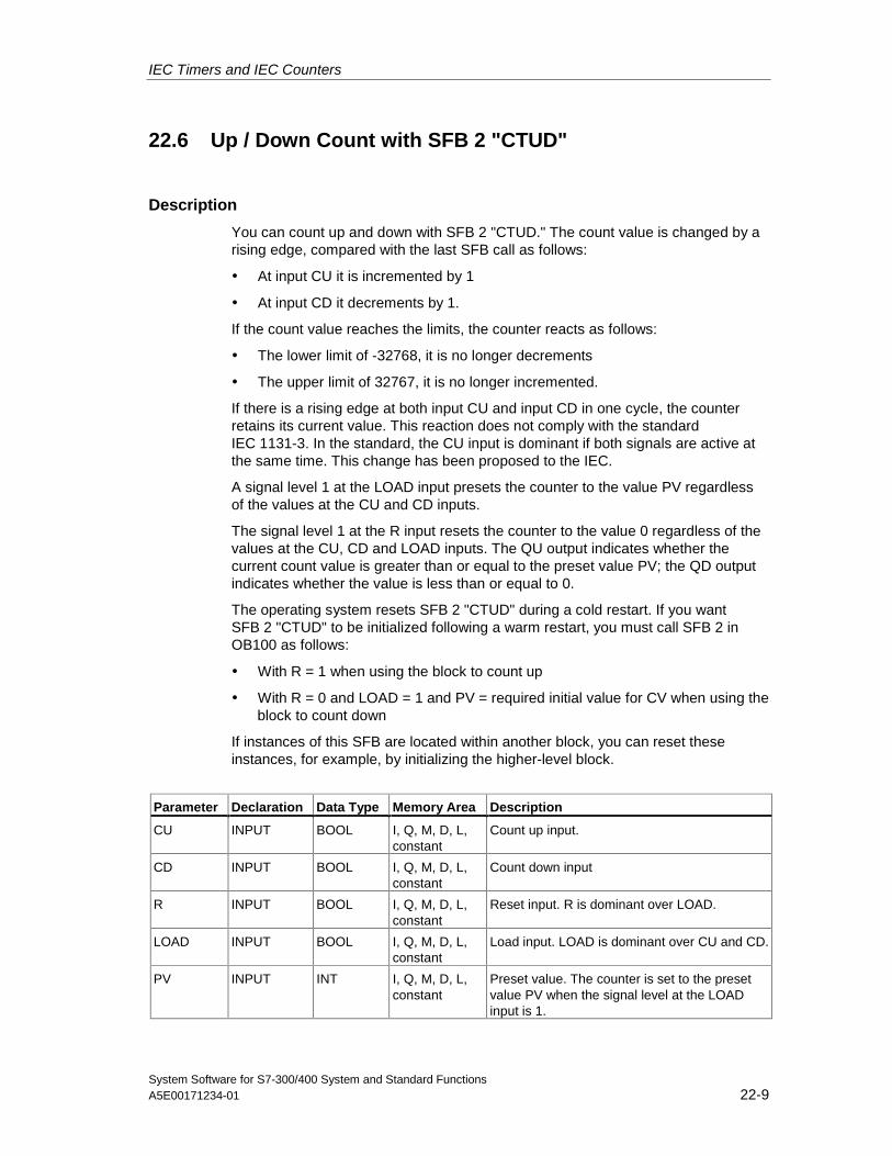
IEC Timers and IEC Counters
System Software for S7-300/400 System and Standard FunctionsA5E00171234-01 22-9
22.6 Up / Down Count with SFB 2 "CTUD"
Description
You can count up and down with SFB 2 "CTUD." The count value is changed by arising edge, compared with the last SFB call as follows:
• At input CU it is incremented by 1
• At input CD it decrements by 1.
If the count value reaches the limits, the counter reacts as follows:
• The lower limit of -32768, it is no longer decrements
• The upper limit of 32767, it is no longer incremented.
If there is a rising edge at both input CU and input CD in one cycle, the counterretains its current value. This reaction does not comply with the standardIEC 1131-3. In the standard, the CU input is dominant if both signals are active atthe same time. This change has been proposed to the IEC.
A signal level 1 at the LOAD input presets the counter to the value PV regardlessof the values at the CU and CD inputs.
The signal level 1 at the R input resets the counter to the value 0 regardless of thevalues at the CU, CD and LOAD inputs. The QU output indicates whether thecurrent count value is greater than or equal to the preset value PV; the QD outputindicates whether the value is less than or equal to 0.
The operating system resets SFB 2 "CTUD" during a cold restart. If you wantSFB 2 "CTUD" to be initialized following a warm restart, you must call SFB 2 inOB100 as follows:
• With R = 1 when using the block to count up
• With R = 0 and LOAD = 1 and PV = required initial value for CV when using theblock to count down
If instances of this SFB are located within another block, you can reset theseinstances, for example, by initializing the higher-level block.
Parameter Declaration Data Type Memory Area Description
CU INPUT BOOL I, Q, M, D, L,constant
Count up input.
CD INPUT BOOL I, Q, M, D, L,constant
Count down input
R INPUT BOOL I, Q, M, D, L,constant
Reset input. R is dominant over LOAD.
LOAD INPUT BOOL I, Q, M, D, L,constant
Load input. LOAD is dominant over CU and CD.
PV INPUT INT I, Q, M, D, L,constant
Preset value. The counter is set to the presetvalue PV when the signal level at the LOADinput is 1.
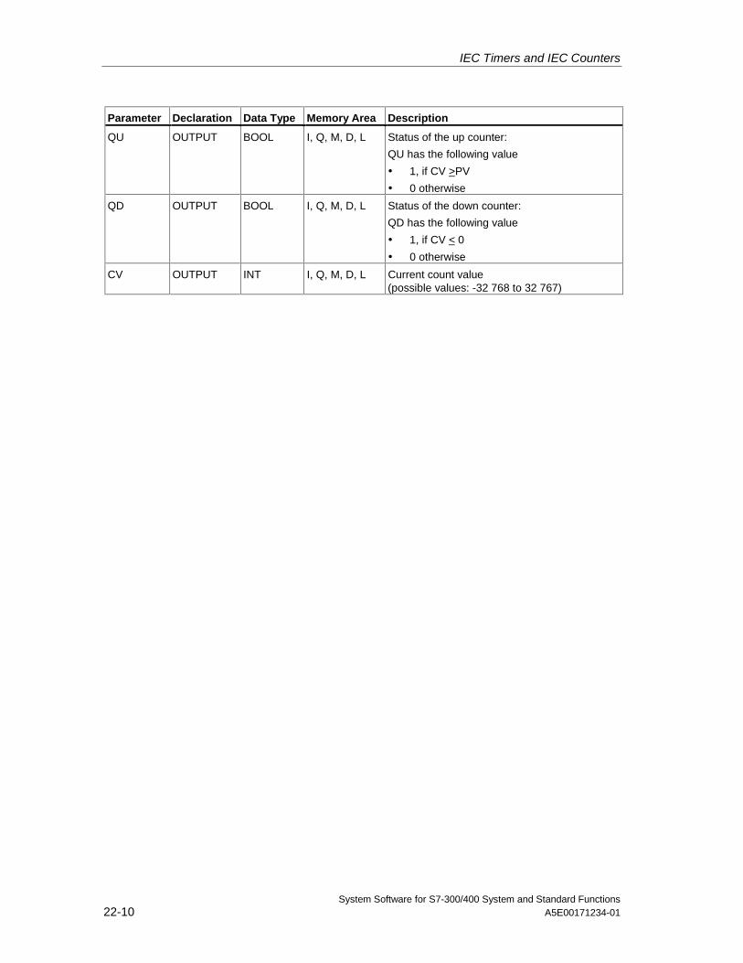
IEC Timers and IEC Counters
System Software for S7-300/400 System and Standard Functions22-10 A5E00171234-01
Parameter Declaration Data Type Memory Area Description
QU OUTPUT BOOL I, Q, M, D, L Status of the up counter:
QU has the following value
• 1, if CV >PV
• 0 otherwise
QD OUTPUT BOOL I, Q, M, D, L Status of the down counter:
QD has the following value
• 1, if CV < 0
• 0 otherwise
CV OUTPUT INT I, Q, M, D, L Current count value(possible values: -32 768 to 32 767)
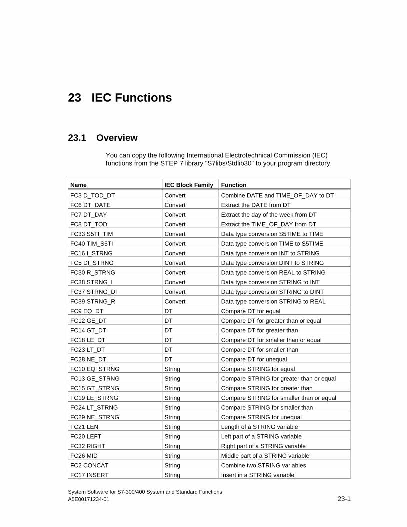
System Software for S7-300/400 System and Standard FunctionsA5E00171234-01 23-1
23 IEC Functions
23.1 Overview
You can copy the following International Electrotechnical Commission (IEC)functions from the STEP 7 library "S7libs\Stdlib30" to your program directory.
Name IEC Block Family Function
FC3 D_TOD_DT Convert Combine DATE and TIME_OF_DAY to DT
FC6 DT_DATE Convert Extract the DATE from DT
FC7 DT_DAY Convert Extract the day of the week from DT
FC8 DT_TOD Convert Extract the TIME_OF_DAY from DT
FC33 S5TI_TIM Convert Data type conversion S5TIME to TIME
FC40 TIM_S5TI Convert Data type conversion TIME to S5TIME
FC16 I_STRNG Convert Data type conversion INT to STRING
FC5 DI_STRNG Convert Data type conversion DINT to STRING
FC30 R_STRNG Convert Data type conversion REAL to STRING
FC38 STRNG_I Convert Data type conversion STRING to INT
FC37 STRNG_DI Convert Data type conversion STRING to DINT
FC39 STRNG_R Convert Data type conversion STRING to REAL
FC9 EQ_DT DT Compare DT for equal
FC12 GE_DT DT Compare DT for greater than or equal
FC14 GT_DT DT Compare DT for greater than
FC18 LE_DT DT Compare DT for smaller than or equal
FC23 LT_DT DT Compare DT for smaller than
FC28 NE_DT DT Compare DT for unequal
FC10 EQ_STRNG String Compare STRING for equal
FC13 GE_STRNG String Compare STRING for greater than or equal
FC15 GT_STRNG String Compare STRING for greater than
FC19 LE_STRNG String Compare STRING for smaller than or equal
FC24 LT_STRNG String Compare STRING for smaller than
FC29 NE_STRNG String Compare STRING for unequal
FC21 LEN String Length of a STRING variable
FC20 LEFT String Left part of a STRING variable
FC32 RIGHT String Right part of a STRING variable
FC26 MID String Middle part of a STRING variable
FC2 CONCAT String Combine two STRING variables
FC17 INSERT String Insert in a STRING variable
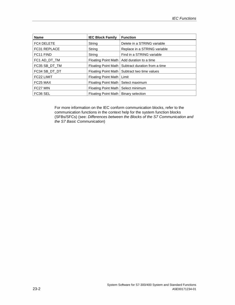
IEC Functions
System Software for S7-300/400 System and Standard Functions23-2 A5E00171234-01
Name IEC Block Family Function
FC4 DELETE String Delete in a STRING variable
FC31 REPLACE String Replace in a STRING variable
FC11 FIND String Find in a STRING variable
FC1 AD_DT_TM Floating Point Math Add duration to a time
FC35 SB_DT_TM Floating Point Math Subtract duration from a time
FC34 SB_DT_DT Floating Point Math Subtract two time values
FC22 LIMIT Floating Point Math Limit
FC25 MAX Floating Point Math Select maximum
FC27 MIN Floating Point Math Select minimum
FC36 SEL Floating Point Math Binary selection
For more information on the IEC conform communication blocks, refer to thecommunication functions in the context help for the system function blocks(SFBs/SFCs) (see: Differences between the Blocks of the S7 Communication andthe S7 Basic Communication)
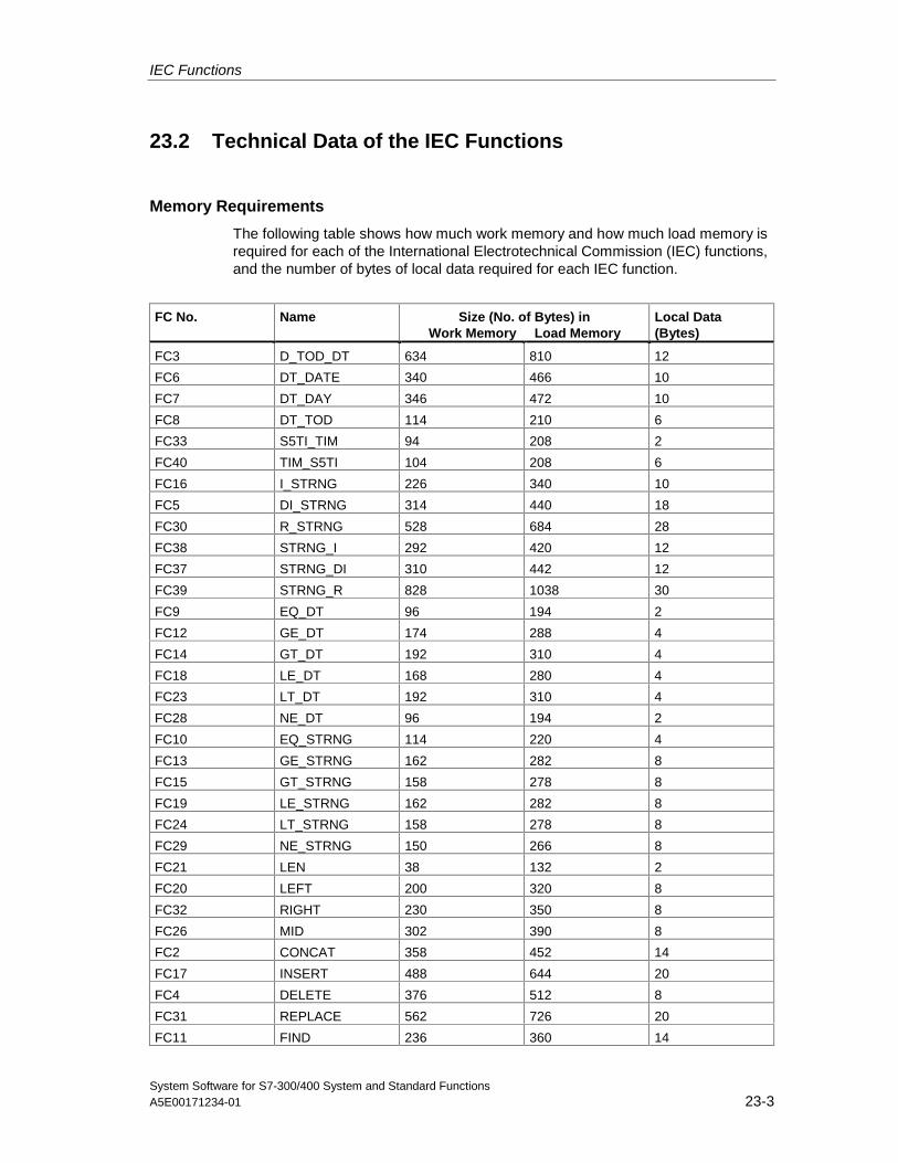
IEC Functions
System Software for S7-300/400 System and Standard FunctionsA5E00171234-01 23-3
23.2 Technical Data of the IEC Functions
Memory Requirements
The following table shows how much work memory and how much load memory isrequired for each of the International Electrotechnical Commission (IEC) functions,and the number of bytes of local data required for each IEC function.
FC No. Name Size (No. of Bytes) inWork Memory Load Memory
Local Data(Bytes)
FC3 D_TOD_DT 634 810 12
FC6 DT_DATE 340 466 10
FC7 DT_DAY 346 472 10
FC8 DT_TOD 114 210 6
FC33 S5TI_TIM 94 208 2
FC40 TIM_S5TI 104 208 6
FC16 I_STRNG 226 340 10
FC5 DI_STRNG 314 440 18
FC30 R_STRNG 528 684 28
FC38 STRNG_I 292 420 12
FC37 STRNG_DI 310 442 12
FC39 STRNG_R 828 1038 30
FC9 EQ_DT 96 194 2
FC12 GE_DT 174 288 4
FC14 GT_DT 192 310 4
FC18 LE_DT 168 280 4
FC23 LT_DT 192 310 4
FC28 NE_DT 96 194 2
FC10 EQ_STRNG 114 220 4
FC13 GE_STRNG 162 282 8
FC15 GT_STRNG 158 278 8
FC19 LE_STRNG 162 282 8
FC24 LT_STRNG 158 278 8
FC29 NE_STRNG 150 266 8
FC21 LEN 38 132 2
FC20 LEFT 200 320 8
FC32 RIGHT 230 350 8
FC26 MID 302 390 8
FC2 CONCAT 358 452 14
FC17 INSERT 488 644 20
FC4 DELETE 376 512 8
FC31 REPLACE 562 726 20
FC11 FIND 236 360 14
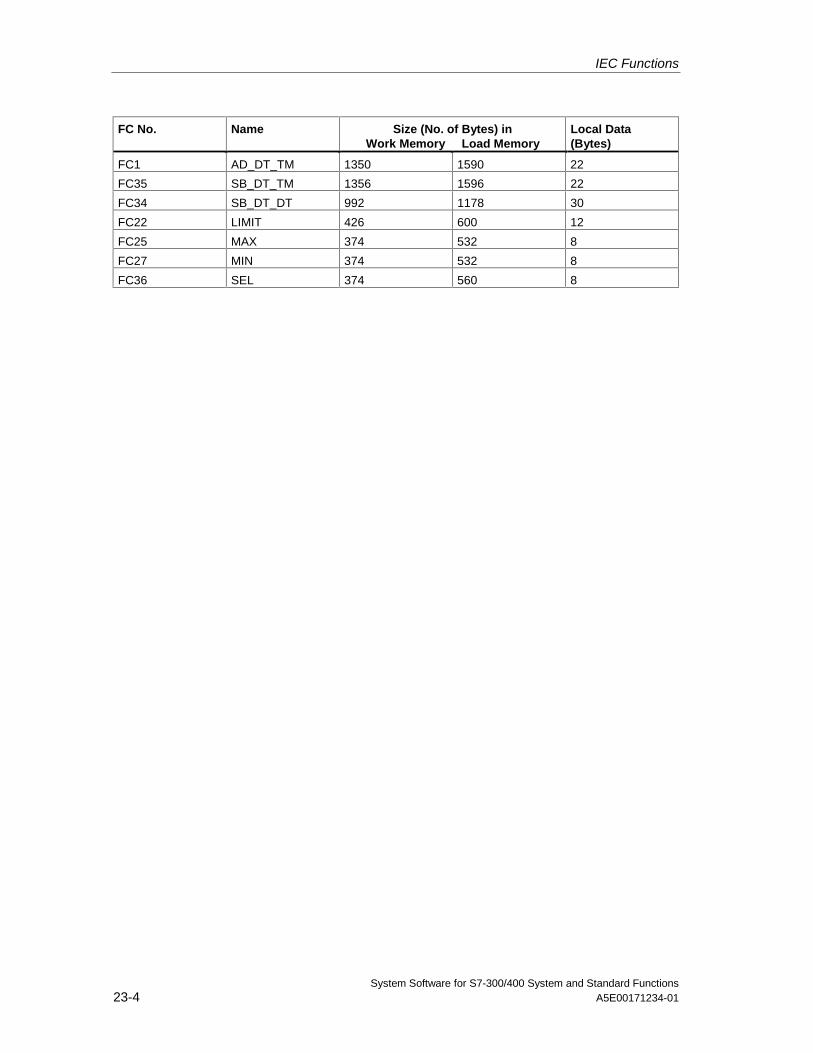
IEC Functions
System Software for S7-300/400 System and Standard Functions23-4 A5E00171234-01
FC No. Name Size (No. of Bytes) inWork Memory Load Memory
Local Data(Bytes)
FC1 AD_DT_TM 1350 1590 22
FC35 SB_DT_TM 1356 1596 22
FC34 SB_DT_DT 992 1178 30
FC22 LIMIT 426 600 12
FC25 MAX 374 532 8
FC27 MIN 374 532 8
FC36 SEL 374 560 8
IEC Functions
System Software for S7-300/400 System and Standard FunctionsA5E00171234-01 23-5
23.3 Date and Time as Complex Data Types
Actual Parameters for DATE_AND_TIME
The DATE_AND_TIME data type falls into the category of complex data types,along with ARRAY, STRING, and STRUCT. The permissible memory areas forcomplex data types are the data block (D) and local data (L) areas.
Because DATE_AND_TIME is a complex data type, when you useDATE_AND_TIME as a formal parameter in a statement, you can provide theactual parameter only in one of the following forms:
• A block-specific symbol from the variable declaration table for a specific block
• A symbolic name for a data block, such as "DB_sys_info.System_Time", madeup of the following parts:
- A name defined in the symbol table for the number of the data block (forexample, "DB_sys_info" for DB5)
- A name defined within the data block for the DATE_AND_TIME element (forexample, "System_Time" for a variable of data type DATE_AND_TIMEcontained in DB5)
You cannot pass constants as actual parameters to formal parameters of thecomplex data types, including DATE_AND_TIME. Also, you cannot pass absoluteaddresses as actual parameters to DATE_AND_TIME.
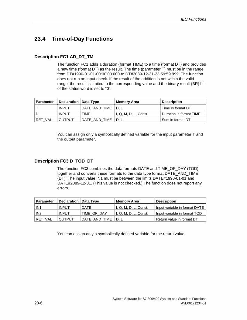
IEC Functions
System Software for S7-300/400 System and Standard Functions23-6 A5E00171234-01
23.4 Time-of-Day Functions
Description FC1 AD_DT_TM
The function FC1 adds a duration (format TIME) to a time (format DT) and providesa new time (format DT) as the result. The time (parameter T) must be in the rangefrom DT#1990-01-01-00:00:00.000 to DT#2089-12-31-23:59:59.999. The functiondoes not run an input check. If the result of the addition is not within the validrange, the result is limited to the corresponding value and the binary result (BR) bitof the status word is set to “0".
Parameter Declaration Data Type Memory Area Description
T INPUT DATE_AND_TIME D, L Time in format DT
D INPUT TIME I, Q, M, D, L, Const. Duration in format TIME
RET_VAL OUTPUT DATE_AND_TIME D, L Sum in format DT
You can assign only a symbolically defined variable for the input parameter T andthe output parameter.
Description FC3 D_TOD_DT
The function FC3 combines the data formats DATE and TIME_OF_DAY (TOD)together and converts these formats to the data type format DATE_AND_TIME(DT). The input value IN1 must be between the limits DATE#1990-01-01 andDATE#2089-12-31. (This value is not checked.) The function does not report anyerrors.
Parameter Declaration Data Type Memory Area Description
IN1 INPUT DATE I, Q, M, D, L, Const. Input variable in format DATE
IN2 INPUT TIME_OF_DAY I, Q, M, D, L, Const. Input variable in format TOD
RET_VAL OUTPUT DATE_AND_TIME D, L Return value in format DT
You can assign only a symbolically defined variable for the return value.
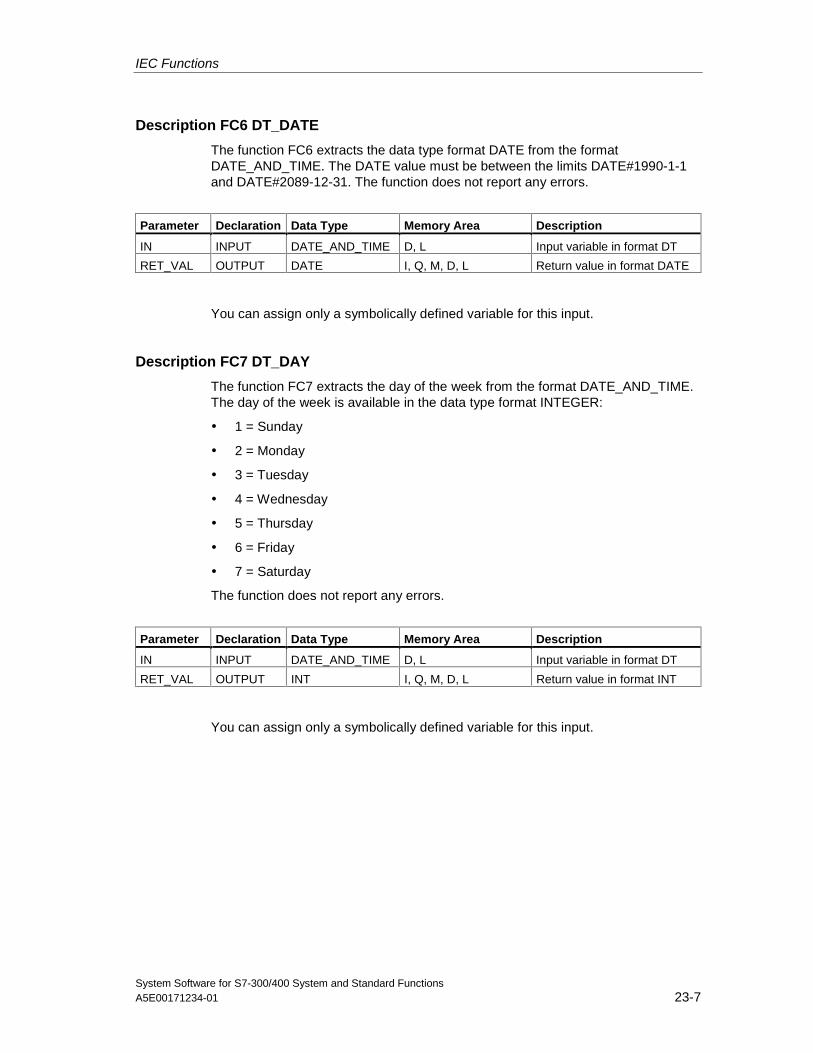
IEC Functions
System Software for S7-300/400 System and Standard FunctionsA5E00171234-01 23-7
Description FC6 DT_DATE
The function FC6 extracts the data type format DATE from the formatDATE_AND_TIME. The DATE value must be between the limits DATE#1990-1-1and DATE#2089-12-31. The function does not report any errors.
Parameter Declaration Data Type Memory Area Description
IN INPUT DATE_AND_TIME D, L Input variable in format DT
RET_VAL OUTPUT DATE I, Q, M, D, L Return value in format DATE
You can assign only a symbolically defined variable for this input.
Description FC7 DT_DAY
The function FC7 extracts the day of the week from the format DATE_AND_TIME.The day of the week is available in the data type format INTEGER:
• 1 = Sunday
• 2 = Monday
• 3 = Tuesday
• 4 = Wednesday
• 5 = Thursday
• 6 = Friday
• 7 = Saturday
The function does not report any errors.
Parameter Declaration Data Type Memory Area Description
IN INPUT DATE_AND_TIME D, L Input variable in format DT
RET_VAL OUTPUT INT I, Q, M, D, L Return value in format INT
You can assign only a symbolically defined variable for this input.
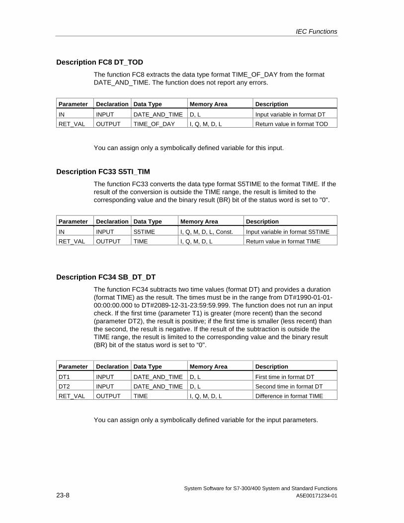
IEC Functions
System Software for S7-300/400 System and Standard Functions23-8 A5E00171234-01
Description FC8 DT_TOD
The function FC8 extracts the data type format TIME_OF_DAY from the formatDATE_AND_TIME. The function does not report any errors.
Parameter Declaration Data Type Memory Area Description
IN INPUT DATE_AND_TIME D, L Input variable in format DT
RET_VAL OUTPUT TIME_OF_DAY I, Q, M, D, L Return value in format TOD
You can assign only a symbolically defined variable for this input.
Description FC33 S5TI_TIM
The function FC33 converts the data type format S5TIME to the format TIME. If theresult of the conversion is outside the TIME range, the result is limited to thecorresponding value and the binary result (BR) bit of the status word is set to "0".
Parameter Declaration Data Type Memory Area Description
IN INPUT S5TIME I, Q, M, D, L, Const. Input variable in format S5TIME
RET_VAL OUTPUT TIME I, Q, M, D, L Return value in format TIME
Description FC34 SB_DT_DT
The function FC34 subtracts two time values (format DT) and provides a duration(format TIME) as the result. The times must be in the range from DT#1990-01-01-00:00:00.000 to DT#2089-12-31-23:59:59.999. The function does not run an inputcheck. If the first time (parameter T1) is greater (more recent) than the second(parameter DT2), the result is positive; if the first time is smaller (less recent) thanthe second, the result is negative. If the result of the subtraction is outside theTIME range, the result is limited to the corresponding value and the binary result(BR) bit of the status word is set to “0".
Parameter Declaration Data Type Memory Area Description
DT1 INPUT DATE_AND_TIME D, L First time in format DT
DT2 INPUT DATE_AND_TIME D, L Second time in format DT
RET_VAL OUTPUT TIME I, Q, M, D, L Difference in format TIME
You can assign only a symbolically defined variable for the input parameters.
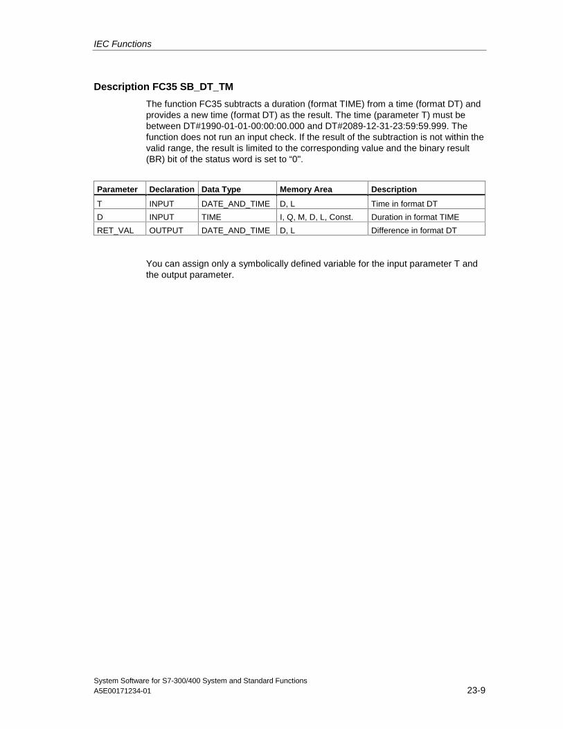
IEC Functions
System Software for S7-300/400 System and Standard FunctionsA5E00171234-01 23-9
Description FC35 SB_DT_TM
The function FC35 subtracts a duration (format TIME) from a time (format DT) andprovides a new time (format DT) as the result. The time (parameter T) must bebetween DT#1990-01-01-00:00:00.000 and DT#2089-12-31-23:59:59.999. Thefunction does not run an input check. If the result of the subtraction is not within thevalid range, the result is limited to the corresponding value and the binary result(BR) bit of the status word is set to “0".
Parameter Declaration Data Type Memory Area Description
T INPUT DATE_AND_TIME D, L Time in format DT
D INPUT TIME I, Q, M, D, L, Const. Duration in format TIME
RET_VAL OUTPUT DATE_AND_TIME D, L Difference in format DT
You can assign only a symbolically defined variable for the input parameter T andthe output parameter.
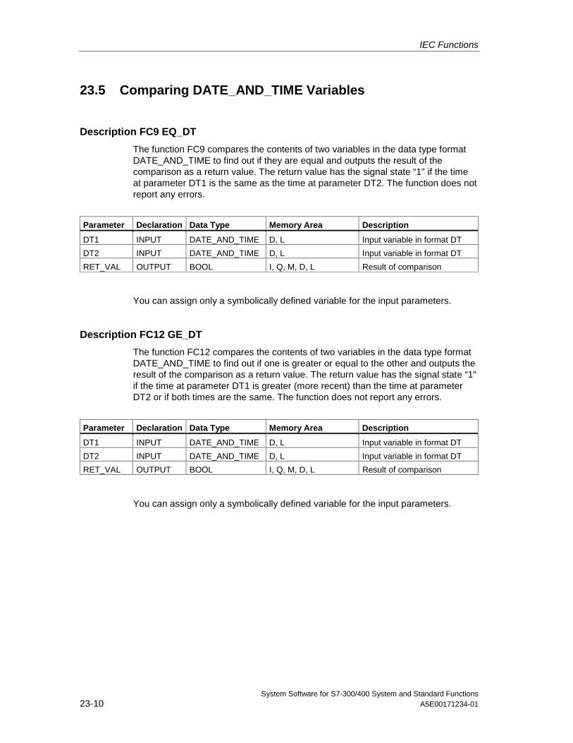
IEC Functions
System Software for S7-300/400 System and Standard Functions23-10 A5E00171234-01
23.5 Comparing DATE_AND_TIME Variables
Description FC9 EQ_DT
The function FC9 compares the contents of two variables in the data type formatDATE_AND_TIME to find out if they are equal and outputs the result of thecomparison as a return value. The return value has the signal state “1" if the timeat parameter DT1 is the same as the time at parameter DT2. The function does notreport any errors.
Parameter Declaration Data Type Memory Area Description
DT1 INPUT DATE_AND_TIME D, L Input variable in format DT
DT2 INPUT DATE_AND_TIME D, L Input variable in format DT
RET_VAL OUTPUT BOOL I, Q, M, D, L Result of comparison
You can assign only a symbolically defined variable for the input parameters.
Description FC12 GE_DT
The function FC12 compares the contents of two variables in the data type formatDATE_AND_TIME to find out if one is greater or equal to the other and outputs theresult of the comparison as a return value. The return value has the signal state “1"if the time at parameter DT1 is greater (more recent) than the time at parameterDT2 or if both times are the same. The function does not report any errors.
Parameter Declaration Data Type Memory Area Description
DT1 INPUT DATE_AND_TIME D, L Input variable in format DT
DT2 INPUT DATE_AND_TIME D, L Input variable in format DT
RET_VAL OUTPUT BOOL I, Q, M, D, L Result of comparison
You can assign only a symbolically defined variable for the input parameters.
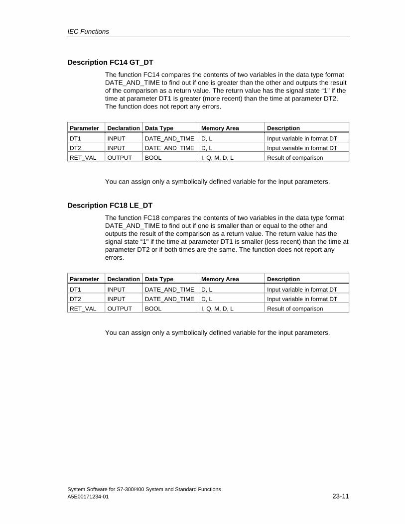
IEC Functions
System Software for S7-300/400 System and Standard FunctionsA5E00171234-01 23-11
Description FC14 GT_DT
The function FC14 compares the contents of two variables in the data type formatDATE_AND_TIME to find out if one is greater than the other and outputs the resultof the comparison as a return value. The return value has the signal state “1" if thetime at parameter DT1 is greater (more recent) than the time at parameter DT2.The function does not report any errors.
Parameter Declaration Data Type Memory Area Description
DT1 INPUT DATE_AND_TIME D, L Input variable in format DT
DT2 INPUT DATE_AND_TIME D, L Input variable in format DT
RET_VAL OUTPUT BOOL I, Q, M, D, L Result of comparison
You can assign only a symbolically defined variable for the input parameters.
Description FC18 LE_DT
The function FC18 compares the contents of two variables in the data type formatDATE_AND_TIME to find out if one is smaller than or equal to the other andoutputs the result of the comparison as a return value. The return value has thesignal state “1" if the time at parameter DT1 is smaller (less recent) than the time atparameter DT2 or if both times are the same. The function does not report anyerrors.
Parameter Declaration Data Type Memory Area Description
DT1 INPUT DATE_AND_TIME D, L Input variable in format DT
DT2 INPUT DATE_AND_TIME D, L Input variable in format DT
RET_VAL OUTPUT BOOL I, Q, M, D, L Result of comparison
You can assign only a symbolically defined variable for the input parameters.
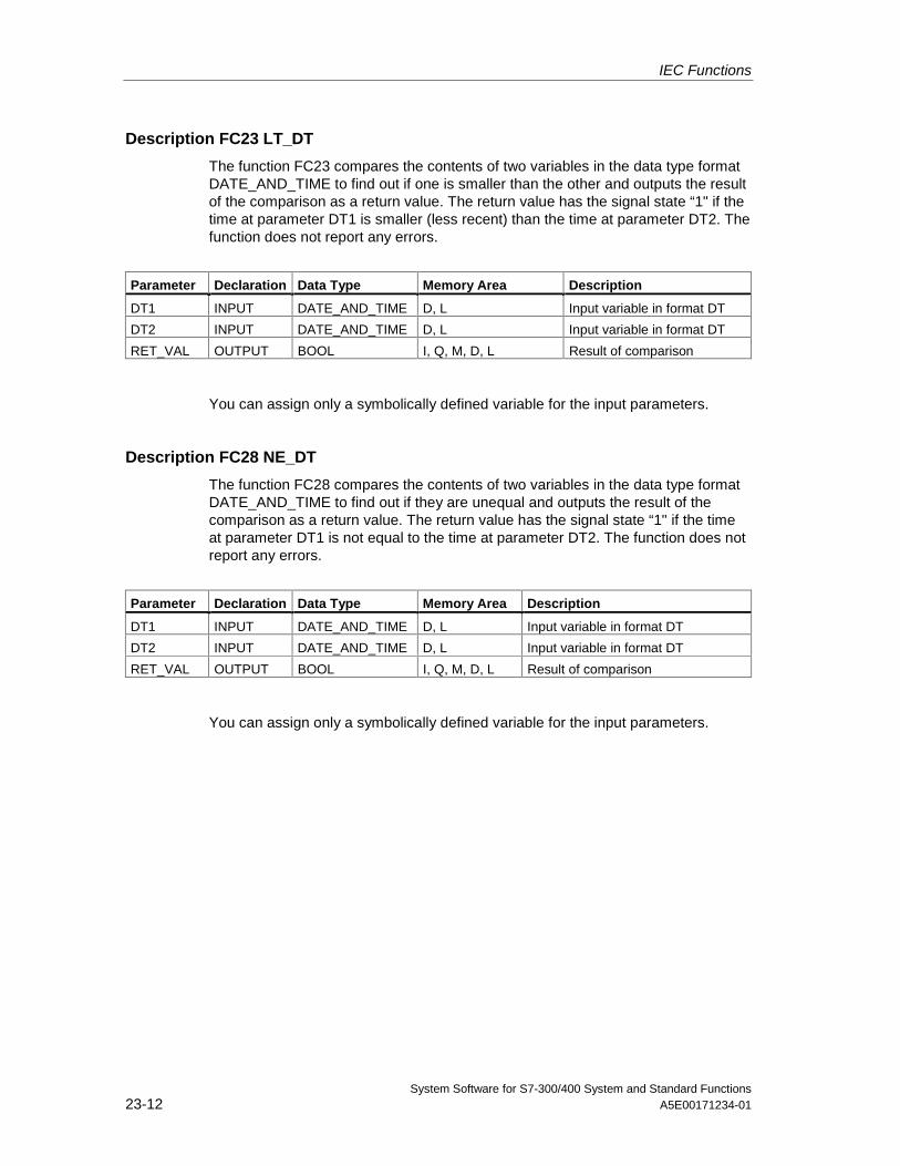
IEC Functions
System Software for S7-300/400 System and Standard Functions23-12 A5E00171234-01
Description FC23 LT_DT
The function FC23 compares the contents of two variables in the data type formatDATE_AND_TIME to find out if one is smaller than the other and outputs the resultof the comparison as a return value. The return value has the signal state “1" if thetime at parameter DT1 is smaller (less recent) than the time at parameter DT2. Thefunction does not report any errors.
Parameter Declaration Data Type Memory Area Description
DT1 INPUT DATE_AND_TIME D, L Input variable in format DT
DT2 INPUT DATE_AND_TIME D, L Input variable in format DT
RET_VAL OUTPUT BOOL I, Q, M, D, L Result of comparison
You can assign only a symbolically defined variable for the input parameters.
Description FC28 NE_DT
The function FC28 compares the contents of two variables in the data type formatDATE_AND_TIME to find out if they are unequal and outputs the result of thecomparison as a return value. The return value has the signal state “1" if the timeat parameter DT1 is not equal to the time at parameter DT2. The function does notreport any errors.
Parameter Declaration Data Type Memory Area Description
DT1 INPUT DATE_AND_TIME D, L Input variable in format DT
DT2 INPUT DATE_AND_TIME D, L Input variable in format DT
RET_VAL OUTPUT BOOL I, Q, M, D, L Result of comparison
You can assign only a symbolically defined variable for the input parameters.
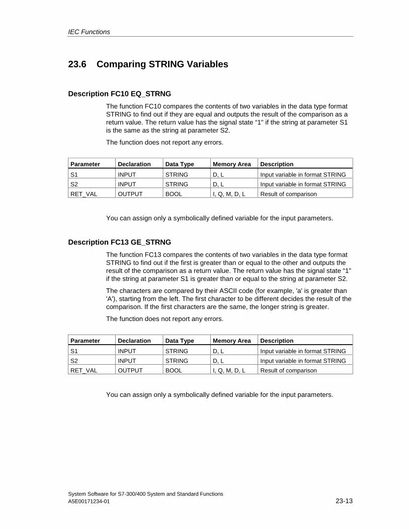
IEC Functions
System Software for S7-300/400 System and Standard FunctionsA5E00171234-01 23-13
23.6 Comparing STRING Variables
Description FC10 EQ_STRNG
The function FC10 compares the contents of two variables in the data type formatSTRING to find out if they are equal and outputs the result of the comparison as areturn value. The return value has the signal state “1" if the string at parameter S1is the same as the string at parameter S2.
The function does not report any errors.
Parameter Declaration Data Type Memory Area Description
S1 INPUT STRING D, L Input variable in format STRING
S2 INPUT STRING D, L Input variable in format STRING
RET_VAL OUTPUT BOOL I, Q, M, D, L Result of comparison
You can assign only a symbolically defined variable for the input parameters.
Description FC13 GE_STRNG
The function FC13 compares the contents of two variables in the data type formatSTRING to find out if the first is greater than or equal to the other and outputs theresult of the comparison as a return value. The return value has the signal state “1"if the string at parameter S1 is greater than or equal to the string at parameter S2.
The characters are compared by their ASCII code (for example, 'a' is greater than'A'), starting from the left. The first character to be different decides the result of thecomparison. If the first characters are the same, the longer string is greater.
The function does not report any errors.
Parameter Declaration Data Type Memory Area Description
S1 INPUT STRING D, L Input variable in format STRING
S2 INPUT STRING D, L Input variable in format STRING
RET_VAL OUTPUT BOOL I, Q, M, D, L Result of comparison
You can assign only a symbolically defined variable for the input parameters.
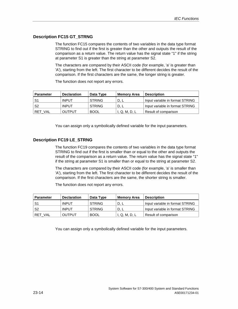
IEC Functions
System Software for S7-300/400 System and Standard Functions23-14 A5E00171234-01
Description FC15 GT_STRNG
The function FC15 compares the contents of two variables in the data type formatSTRING to find out if the first is greater than the other and outputs the result of thecomparison as a return value. The return value has the signal state “1" if the stringat parameter S1 is greater than the string at parameter S2.
The characters are compared by their ASCII code (for example, 'a' is greater than'A'), starting from the left. The first character to be different decides the result of thecomparison. If the first characters are the same, the longer string is greater.
The function does not report any errors.
Parameter Declaration Data Type Memory Area Description
S1 INPUT STRING D, L Input variable in format STRING
S2 INPUT STRING D, L Input variable in format STRING
RET_VAL OUTPUT BOOL I, Q, M, D, L Result of comparison
You can assign only a symbolically defined variable for the input parameters.
Description FC19 LE_STRNG
The function FC19 compares the contents of two variables in the data type formatSTRING to find out if the first is smaller than or equal to the other and outputs theresult of the comparison as a return value. The return value has the signal state “1"if the string at parameter S1 is smaller than or equal to the string at parameter S2.
The characters are compared by their ASCII code (for example, 'a' is smaller than'A'), starting from the left. The first character to be different decides the result of thecomparison. If the first characters are the same, the shorter string is smaller.
The function does not report any errors.
Parameter Declaration Data Type Memory Area Description
S1 INPUT STRING D, L Input variable in format STRING
S2 INPUT STRING D, L Input variable in format STRING
RET_VAL OUTPUT BOOL I, Q, M, D, L Result of comparison
You can assign only a symbolically defined variable for the input parameters.
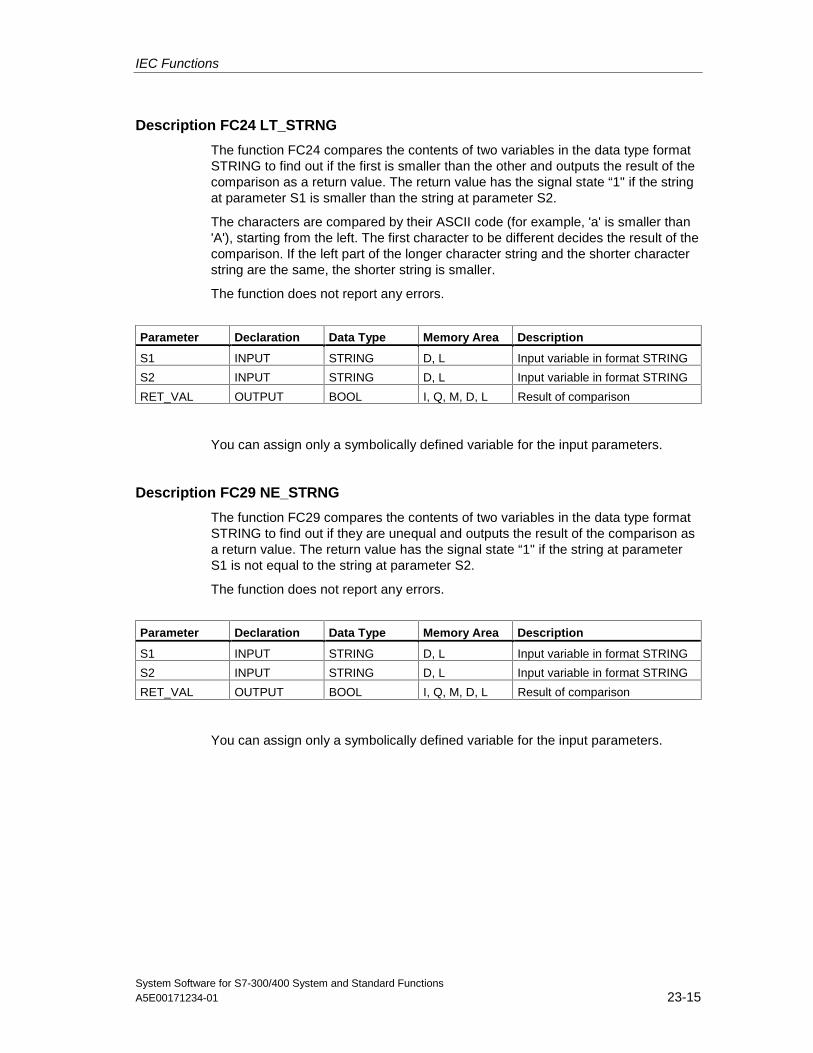
IEC Functions
System Software for S7-300/400 System and Standard FunctionsA5E00171234-01 23-15
Description FC24 LT_STRNG
The function FC24 compares the contents of two variables in the data type formatSTRING to find out if the first is smaller than the other and outputs the result of thecomparison as a return value. The return value has the signal state “1" if the stringat parameter S1 is smaller than the string at parameter S2.
The characters are compared by their ASCII code (for example, 'a' is smaller than'A'), starting from the left. The first character to be different decides the result of thecomparison. If the left part of the longer character string and the shorter characterstring are the same, the shorter string is smaller.
The function does not report any errors.
Parameter Declaration Data Type Memory Area Description
S1 INPUT STRING D, L Input variable in format STRING
S2 INPUT STRING D, L Input variable in format STRING
RET_VAL OUTPUT BOOL I, Q, M, D, L Result of comparison
You can assign only a symbolically defined variable for the input parameters.
Description FC29 NE_STRNG
The function FC29 compares the contents of two variables in the data type formatSTRING to find out if they are unequal and outputs the result of the comparison asa return value. The return value has the signal state “1" if the string at parameterS1 is not equal to the string at parameter S2.
The function does not report any errors.
Parameter Declaration Data Type Memory Area Description
S1 INPUT STRING D, L Input variable in format STRING
S2 INPUT STRING D, L Input variable in format STRING
RET_VAL OUTPUT BOOL I, Q, M, D, L Result of comparison
You can assign only a symbolically defined variable for the input parameters.
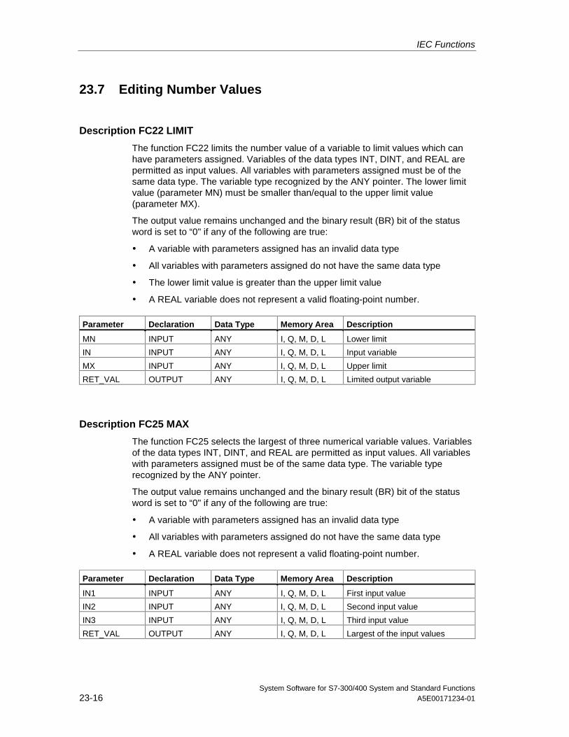
IEC Functions
System Software for S7-300/400 System and Standard Functions23-16 A5E00171234-01
23.7 Editing Number Values
Description FC22 LIMIT
The function FC22 limits the number value of a variable to limit values which canhave parameters assigned. Variables of the data types INT, DINT, and REAL arepermitted as input values. All variables with parameters assigned must be of thesame data type. The variable type recognized by the ANY pointer. The lower limitvalue (parameter MN) must be smaller than/equal to the upper limit value(parameter MX).
The output value remains unchanged and the binary result (BR) bit of the statusword is set to “0" if any of the following are true:
• A variable with parameters assigned has an invalid data type
• All variables with parameters assigned do not have the same data type
• The lower limit value is greater than the upper limit value
• A REAL variable does not represent a valid floating-point number.
Parameter Declaration Data Type Memory Area Description
MN INPUT ANY I, Q, M, D, L Lower limit
IN INPUT ANY I, Q, M, D, L Input variable
MX INPUT ANY I, Q, M, D, L Upper limit
RET_VAL OUTPUT ANY I, Q, M, D, L Limited output variable
Description FC25 MAX
The function FC25 selects the largest of three numerical variable values. Variablesof the data types INT, DINT, and REAL are permitted as input values. All variableswith parameters assigned must be of the same data type. The variable typerecognized by the ANY pointer.
The output value remains unchanged and the binary result (BR) bit of the statusword is set to “0" if any of the following are true:
• A variable with parameters assigned has an invalid data type
• All variables with parameters assigned do not have the same data type
• A REAL variable does not represent a valid floating-point number.
Parameter Declaration Data Type Memory Area Description
IN1 INPUT ANY I, Q, M, D, L First input value
IN2 INPUT ANY I, Q, M, D, L Second input value
IN3 INPUT ANY I, Q, M, D, L Third input value
RET_VAL OUTPUT ANY I, Q, M, D, L Largest of the input values
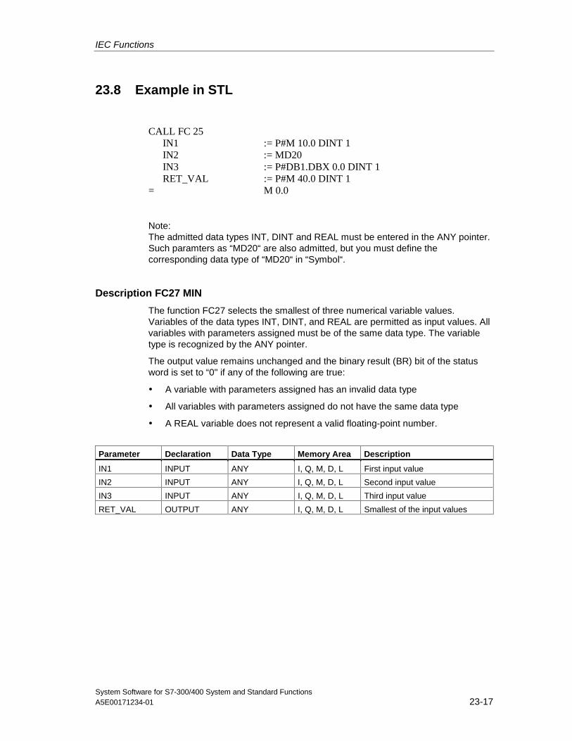
IEC Functions
System Software for S7-300/400 System and Standard FunctionsA5E00171234-01 23-17
23.8 Example in STL
CALL FC 25IN1 := P#M 10.0 DINT 1IN2 := MD20IN3 := P#DB1.DBX 0.0 DINT 1RET_VAL := P#M 40.0 DINT 1
= M 0.0
Note:The admitted data types INT, DINT and REAL must be entered in the ANY pointer.Such paramters as “MD20“ are also admitted, but you must define thecorresponding data type of “MD20“ in “Symbol“.
Description FC27 MIN
The function FC27 selects the smallest of three numerical variable values.Variables of the data types INT, DINT, and REAL are permitted as input values. Allvariables with parameters assigned must be of the same data type. The variabletype is recognized by the ANY pointer.
The output value remains unchanged and the binary result (BR) bit of the statusword is set to “0" if any of the following are true:
• A variable with parameters assigned has an invalid data type
• All variables with parameters assigned do not have the same data type
• A REAL variable does not represent a valid floating-point number.
Parameter Declaration Data Type Memory Area Description
IN1 INPUT ANY I, Q, M, D, L First input value
IN2 INPUT ANY I, Q, M, D, L Second input value
IN3 INPUT ANY I, Q, M, D, L Third input value
RET_VAL OUTPUT ANY I, Q, M, D, L Smallest of the input values
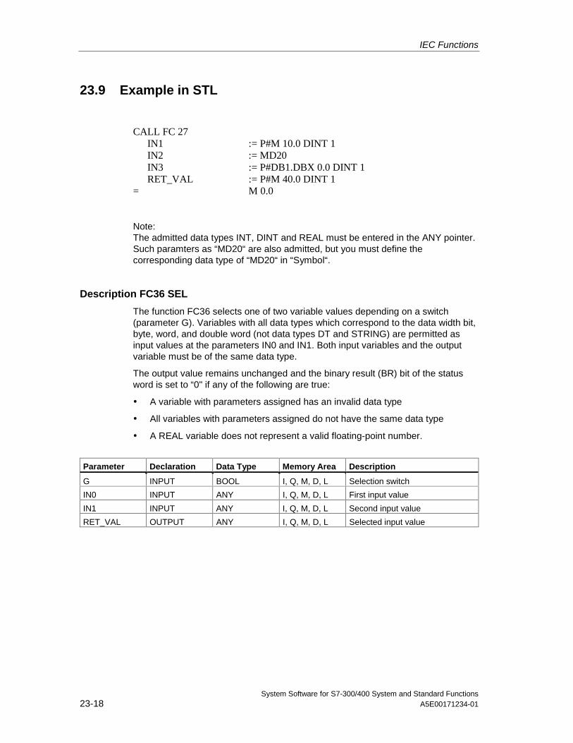
IEC Functions
System Software for S7-300/400 System and Standard Functions23-18 A5E00171234-01
23.9 Example in STL
CALL FC 27IN1 := P#M 10.0 DINT 1IN2 := MD20IN3 := P#DB1.DBX 0.0 DINT 1RET_VAL := P#M 40.0 DINT 1
= M 0.0
Note:The admitted data types INT, DINT and REAL must be entered in the ANY pointer.Such paramters as “MD20“ are also admitted, but you must define thecorresponding data type of “MD20“ in “Symbol“.
Description FC36 SEL
The function FC36 selects one of two variable values depending on a switch(parameter G). Variables with all data types which correspond to the data width bit,byte, word, and double word (not data types DT and STRING) are permitted asinput values at the parameters IN0 and IN1. Both input variables and the outputvariable must be of the same data type.
The output value remains unchanged and the binary result (BR) bit of the statusword is set to “0" if any of the following are true:
• A variable with parameters assigned has an invalid data type
• All variables with parameters assigned do not have the same data type
• A REAL variable does not represent a valid floating-point number.
Parameter Declaration Data Type Memory Area Description
G INPUT BOOL I, Q, M, D, L Selection switch
IN0 INPUT ANY I, Q, M, D, L First input value
IN1 INPUT ANY I, Q, M, D, L Second input value
RET_VAL OUTPUT ANY I, Q, M, D, L Selected input value
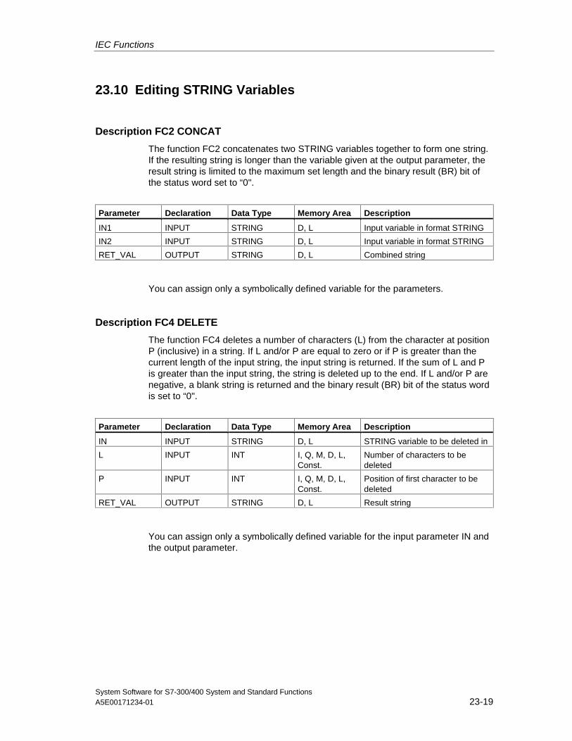
IEC Functions
System Software for S7-300/400 System and Standard FunctionsA5E00171234-01 23-19
23.10 Editing STRING Variables
Description FC2 CONCAT
The function FC2 concatenates two STRING variables together to form one string.If the resulting string is longer than the variable given at the output parameter, theresult string is limited to the maximum set length and the binary result (BR) bit ofthe status word set to “0".
Parameter Declaration Data Type Memory Area Description
IN1 INPUT STRING D, L Input variable in format STRING
IN2 INPUT STRING D, L Input variable in format STRING
RET_VAL OUTPUT STRING D, L Combined string
You can assign only a symbolically defined variable for the parameters.
Description FC4 DELETE
The function FC4 deletes a number of characters (L) from the character at positionP (inclusive) in a string. If L and/or P are equal to zero or if P is greater than thecurrent length of the input string, the input string is returned. If the sum of L and Pis greater than the input string, the string is deleted up to the end. If L and/or P arenegative, a blank string is returned and the binary result (BR) bit of the status wordis set to “0".
Parameter Declaration Data Type Memory Area Description
IN INPUT STRING D, L STRING variable to be deleted in
L INPUT INT I, Q, M, D, L,Const.
Number of characters to bedeleted
P INPUT INT I, Q, M, D, L,Const.
Position of first character to bedeleted
RET_VAL OUTPUT STRING D, L Result string
You can assign only a symbolically defined variable for the input parameter IN andthe output parameter.
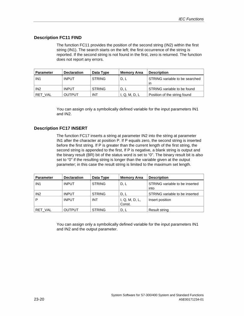
IEC Functions
System Software for S7-300/400 System and Standard Functions23-20 A5E00171234-01
Description FC11 FIND
The function FC11 provides the position of the second string (IN2) within the firststring (IN1). The search starts on the left; the first occurrence of the string isreported. If the second string is not found in the first, zero is returned. The functiondoes not report any errors.
Parameter Declaration Data Type Memory Area Description
IN1 INPUT STRING D, L STRING variable to be searchedin
IN2 INPUT STRING D, L STRING variable to be found
RET_VAL OUTPUT INT I, Q, M, D, L Position of the string found
You can assign only a symbolically defined variable for the input parameters IN1and IN2.
Description FC17 INSERT
The function FC17 inserts a string at parameter IN2 into the string at parameterIN1 after the character at position P. If P equals zero, the second string is insertedbefore the first string. If P is greater than the current length of the first string, thesecond string is appended to the first, If P is negative, a blank string is output andthe binary result (BR) bit of the status word is set to “0". The binary result bit is alsoset to “0" if the resulting string is longer than the variable given at the outputparameter; in this case the result string is limited to the maximum set length.
Parameter Declaration Data Type Memory Area Description
IN1 INPUT STRING D, L STRING variable to be insertedinto
IN2 INPUT STRING D, L STRING variable to be inserted
P INPUT INT I, Q, M, D, L,Const.
Insert position
RET_VAL OUTPUT STRING D, L Result string
You can assign only a symbolically defined variable for the input parameters IN1and IN2 and the output parameter.
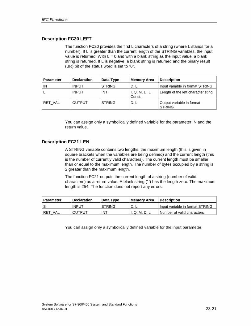
IEC Functions
System Software for S7-300/400 System and Standard FunctionsA5E00171234-01 23-21
Description FC20 LEFT
The function FC20 provides the first L characters of a string (where L stands for anumber). If L is greater than the current length of the STRING variables, the inputvalue is returned. With L = 0 and with a blank string as the input value, a blankstring is returned. If L is negative, a blank string is returned and the binary result(BR) bit of the status word is set to “0".
Parameter Declaration Data Type Memory Area Description
IN INPUT STRING D, L Input variable in format STRING
L INPUT INT I, Q, M, D, L,Const.
Length of the left character sting
RET_VAL OUTPUT STRING D, L Output variable in formatSTRING
You can assign only a symbolically defined variable for the parameter IN and thereturn value.
Description FC21 LEN
A STRING variable contains two lengths: the maximum length (this is given insquare brackets when the variables are being defined) and the current length (thisis the number of currently valid characters). The current length must be smallerthan or equal to the maximum length. The number of bytes occupied by a string is2 greater than the maximum length.
The function FC21 outputs the current length of a string (number of validcharacters) as a return value. A blank string (' ') has the length zero. The maximumlength is 254. The function does not report any errors.
Parameter Declaration Data Type Memory Area Description
S INPUT STRING D, L Input variable in format STRING
RET_VAL OUTPUT INT I, Q, M, D, L Number of valid characters
You can assign only a symbolically defined variable for the input parameter.
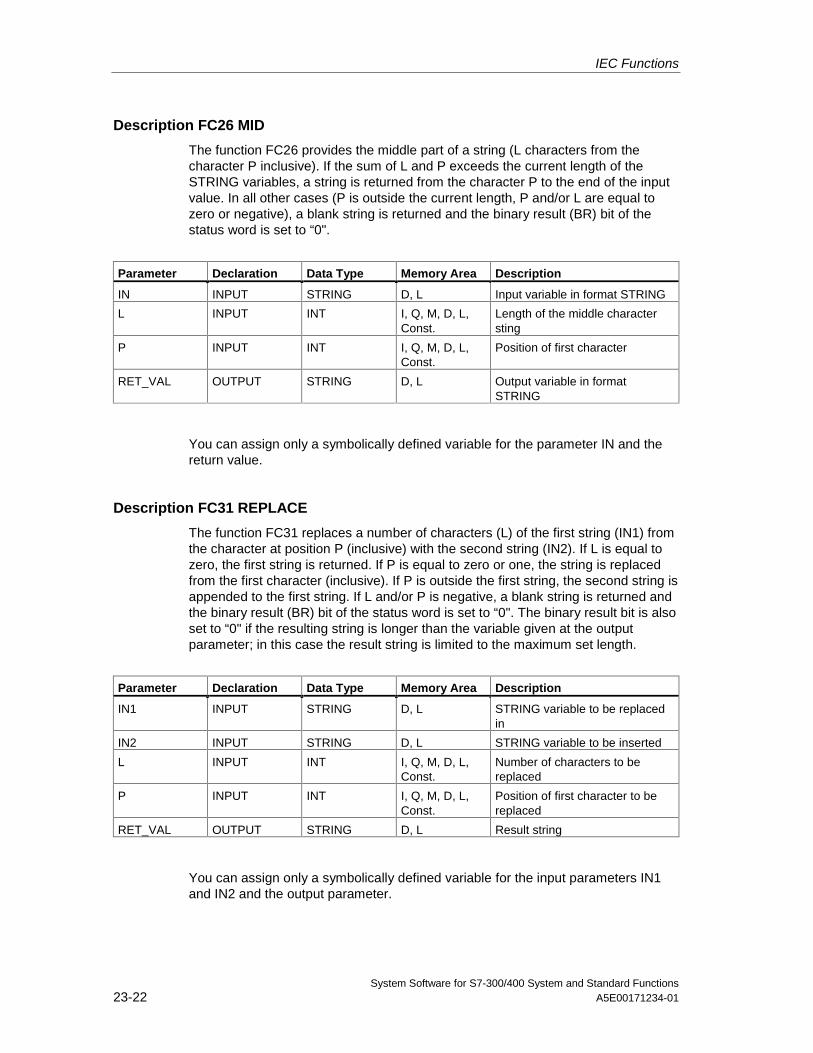
IEC Functions
System Software for S7-300/400 System and Standard Functions23-22 A5E00171234-01
Description FC26 MID
The function FC26 provides the middle part of a string (L characters from thecharacter P inclusive). If the sum of L and P exceeds the current length of theSTRING variables, a string is returned from the character P to the end of the inputvalue. In all other cases (P is outside the current length, P and/or L are equal tozero or negative), a blank string is returned and the binary result (BR) bit of thestatus word is set to “0".
Parameter Declaration Data Type Memory Area Description
IN INPUT STRING D, L Input variable in format STRING
L INPUT INT I, Q, M, D, L,Const.
Length of the middle charactersting
P INPUT INT I, Q, M, D, L,Const.
Position of first character
RET_VAL OUTPUT STRING D, L Output variable in formatSTRING
You can assign only a symbolically defined variable for the parameter IN and thereturn value.
Description FC31 REPLACE
The function FC31 replaces a number of characters (L) of the first string (IN1) fromthe character at position P (inclusive) with the second string (IN2). If L is equal tozero, the first string is returned. If P is equal to zero or one, the string is replacedfrom the first character (inclusive). If P is outside the first string, the second string isappended to the first string. If L and/or P is negative, a blank string is returned andthe binary result (BR) bit of the status word is set to “0". The binary result bit is alsoset to “0" if the resulting string is longer than the variable given at the outputparameter; in this case the result string is limited to the maximum set length.
Parameter Declaration Data Type Memory Area Description
IN1 INPUT STRING D, L STRING variable to be replacedin
IN2 INPUT STRING D, L STRING variable to be inserted
L INPUT INT I, Q, M, D, L,Const.
Number of characters to bereplaced
P INPUT INT I, Q, M, D, L,Const.
Position of first character to bereplaced
RET_VAL OUTPUT STRING D, L Result string
You can assign only a symbolically defined variable for the input parameters IN1and IN2 and the output parameter.
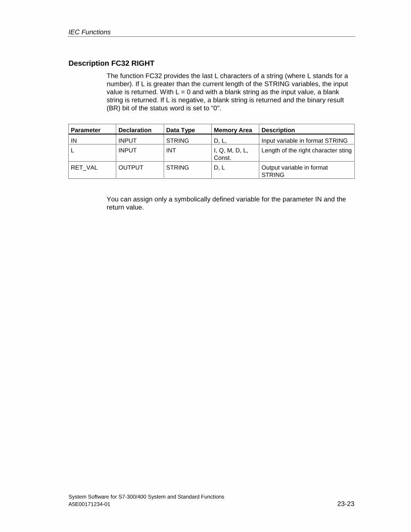
IEC Functions
System Software for S7-300/400 System and Standard FunctionsA5E00171234-01 23-23
Description FC32 RIGHT
The function FC32 provides the last L characters of a string (where L stands for anumber). If L is greater than the current length of the STRING variables, the inputvalue is returned. With L = 0 and with a blank string as the input value, a blankstring is returned. If L is negative, a blank string is returned and the binary result(BR) bit of the status word is set to “0".
Parameter Declaration Data Type Memory Area Description
IN INPUT STRING D, L, Input variable in format STRING
L INPUT INT I, Q, M, D, L,Const.
Length of the right character sting
RET_VAL OUTPUT STRING D, L Output variable in formatSTRING
You can assign only a symbolically defined variable for the parameter IN and thereturn value.
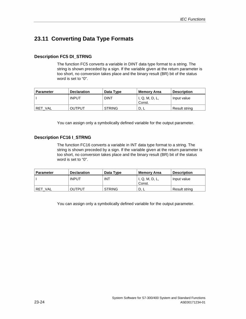
IEC Functions
System Software for S7-300/400 System and Standard Functions23-24 A5E00171234-01
23.11 Converting Data Type Formats
Description FC5 DI_STRNG
The function FC5 converts a variable in DINT data type format to a string. Thestring is shown preceded by a sign. If the variable given at the return parameter istoo short, no conversion takes place and the binary result (BR) bit of the statusword is set to “0".
Parameter Declaration Data Type Memory Area Description
I INPUT DINT I, Q, M, D, L,Const.
Input value
RET_VAL OUTPUT STRING D, L Result string
You can assign only a symbolically defined variable for the output parameter.
Description FC16 I_STRNG
The function FC16 converts a variable in INT data type format to a string. Thestring is shown preceded by a sign. If the variable given at the return parameter istoo short, no conversion takes place and the binary result (BR) bit of the statusword is set to “0".
Parameter Declaration Data Type Memory Area Description
I INPUT INT I, Q, M, D, L,Const.
Input value
RET_VAL OUTPUT STRING D, L Result string
You can assign only a symbolically defined variable for the output parameter.
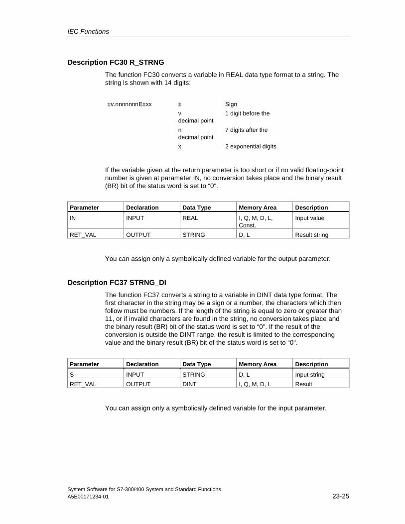
IEC Functions
System Software for S7-300/400 System and Standard FunctionsA5E00171234-01 23-25
Description FC30 R_STRNG
The function FC30 converts a variable in REAL data type format to a string. Thestring is shown with 14 digits:
±v.nnnnnnnE±xx ± Sign
v 1 digit before thedecimal point
n 7 digits after thedecimal point
x 2 exponential digits
If the variable given at the return parameter is too short or if no valid floating-pointnumber is given at parameter IN, no conversion takes place and the binary result(BR) bit of the status word is set to “0".
Parameter Declaration Data Type Memory Area Description
IN INPUT REAL I, Q, M, D, L,Const.
Input value
RET_VAL OUTPUT STRING D, L Result string
You can assign only a symbolically defined variable for the output parameter.
Description FC37 STRNG_DI
The function FC37 converts a string to a variable in DINT data type format. Thefirst character in the string may be a sign or a number, the characters which thenfollow must be numbers. If the length of the string is equal to zero or greater than11, or if invalid characters are found in the string, no conversion takes place andthe binary result (BR) bit of the status word is set to “0". If the result of theconversion is outside the DINT range, the result is limited to the correspondingvalue and the binary result (BR) bit of the status word is set to “0".
Parameter Declaration Data Type Memory Area Description
S INPUT STRING D, L Input string
RET_VAL OUTPUT DINT I, Q, M, D, L Result
You can assign only a symbolically defined variable for the input parameter.
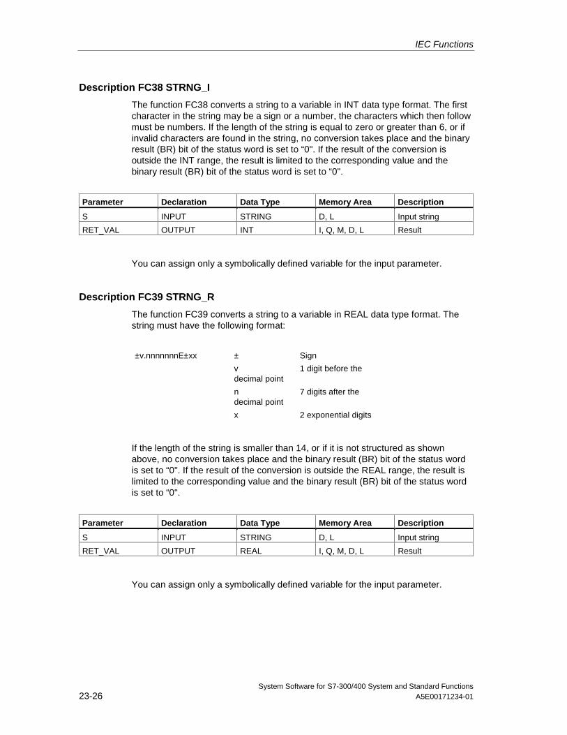
IEC Functions
System Software for S7-300/400 System and Standard Functions23-26 A5E00171234-01
Description FC38 STRNG_I
The function FC38 converts a string to a variable in INT data type format. The firstcharacter in the string may be a sign or a number, the characters which then followmust be numbers. If the length of the string is equal to zero or greater than 6, or ifinvalid characters are found in the string, no conversion takes place and the binaryresult (BR) bit of the status word is set to “0". If the result of the conversion isoutside the INT range, the result is limited to the corresponding value and thebinary result (BR) bit of the status word is set to “0".
Parameter Declaration Data Type Memory Area Description
S INPUT STRING D, L Input string
RET_VAL OUTPUT INT I, Q, M, D, L Result
You can assign only a symbolically defined variable for the input parameter.
Description FC39 STRNG_R
The function FC39 converts a string to a variable in REAL data type format. Thestring must have the following format:
±v.nnnnnnnE±xx ± Sign
v 1 digit before thedecimal point
n 7 digits after thedecimal point
x 2 exponential digits
If the length of the string is smaller than 14, or if it is not structured as shownabove, no conversion takes place and the binary result (BR) bit of the status wordis set to “0". If the result of the conversion is outside the REAL range, the result islimited to the corresponding value and the binary result (BR) bit of the status wordis set to “0".
Parameter Declaration Data Type Memory Area Description
S INPUT STRING D, L Input string
RET_VAL OUTPUT REAL I, Q, M, D, L Result
You can assign only a symbolically defined variable for the input parameter.
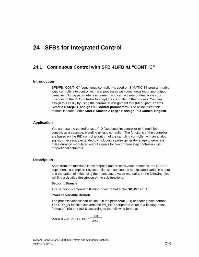
System Software for S7-300/400 System and Standard FunctionsA5E00171234-01 24-1
24 SFBs for Integrated Control
24.1 Continuous Control with SFB 41/FB 41 "CONT_C"
Introduction
SFB/FB "CONT_C" (continuous controller) is used on SIMATIC S7 programmablelogic controllers to control technical processes with continuous input and outputvariables. During parameter assignment, you can activate or deactivate sub-functions of the PID controller to adapt the controller to the process. You canassign this easily by using the parameter assignment tool (Menu path: Start >Simatic > Step7 > Assign PID Control parameters). The online electronicmanual is found under Start > Simatic > Step7 > Assign PID Control English.
Application
You can use the controller as a PID fixed setpoint controller or in multi-loopcontrols as a cascade, blending or ratio controller. The functions of the controllerare based on the PID control algorithm of the sampling controller with an analogsignal, if necessary extended by including a pulse generator stage to generatepulse duration modulated output signals for two or three step controllers withproportional actuators.
Description
Apart from the functions in the setpoint and process value branches, the SFB/FBimplements a complete PID controller with continuous manipulated variable outputand the option of influencing the manipulated value manually. In the following, youwill find a detailed description of the sub-functions:
Setpoint Branch
The setpoint is entered in floating-point format at the SP_INT input.
Process Variable Branch
The process variable can be input in the peripheral (I/O) or floating-point format.The CRP_IN function converts the PV_PER peripheral value to a floating-pointformat of -100 to +100 % according to the following formula:
Output of CPR_IN = PV_PER *100
2764
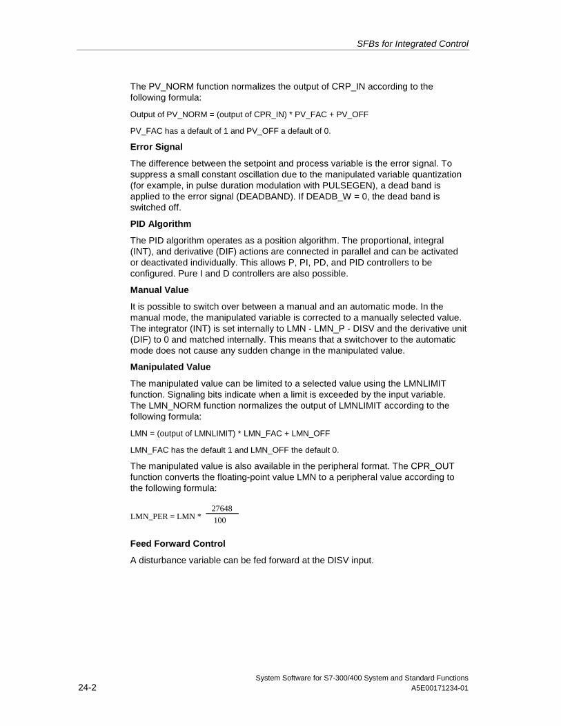
SFBs for Integrated Control
System Software for S7-300/400 System and Standard Functions24-2 A5E00171234-01
The PV_NORM function normalizes the output of CRP_IN according to thefollowing formula:
Output of PV_NORM = (output of CPR_IN) * PV_FAC + PV_OFF
PV_FAC has a default of 1 and PV_OFF a default of 0.
Error Signal
The difference between the setpoint and process variable is the error signal. Tosuppress a small constant oscillation due to the manipulated variable quantization(for example, in pulse duration modulation with PULSEGEN), a dead band isapplied to the error signal (DEADBAND). If DEADB_W = 0, the dead band isswitched off.
PID Algorithm
The PID algorithm operates as a position algorithm. The proportional, integral(INT), and derivative (DIF) actions are connected in parallel and can be activatedor deactivated individually. This allows P, PI, PD, and PID controllers to beconfigured. Pure I and D controllers are also possible.
Manual Value
It is possible to switch over between a manual and an automatic mode. In themanual mode, the manipulated variable is corrected to a manually selected value.The integrator (INT) is set internally to LMN - LMN_P - DISV and the derivative unit(DIF) to 0 and matched internally. This means that a switchover to the automaticmode does not cause any sudden change in the manipulated value.
Manipulated Value
The manipulated value can be limited to a selected value using the LMNLIMITfunction. Signaling bits indicate when a limit is exceeded by the input variable.The LMN_NORM function normalizes the output of LMNLIMIT according to thefollowing formula:
LMN = (output of LMNLIMIT) * LMN_FAC + LMN_OFF
LMN_FAC has the default 1 and LMN_OFF the default 0.
The manipulated value is also available in the peripheral format. The CPR_OUTfunction converts the floating-point value LMN to a peripheral value according tothe following formula:
LMN_PER = LMN * 100
27648
Feed Forward Control
A disturbance variable can be fed forward at the DISV input.
SFBs for Integrated Control
System Software for S7-300/400 System and Standard FunctionsA5E00171234-01 24-3
Initialization
SFB 41 "CONT_C" has an initialization routine that is run through when the inputparameter COM_RST = TRUE is set.
During initialization, the integrator is set internally to the initialization value I_ITVAL.When it is called in a cyclic interrupt priority class, it then continues to work startingat this value.
All other outputs are set to their default values.
Error Information
The error output parameter RET_VAL is not used.
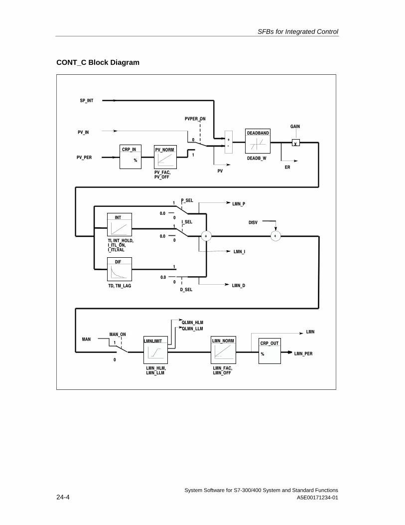
SFBs for Integrated Control
System Software for S7-300/400 System and Standard Functions24-4 A5E00171234-01
CONT_C Block Diagram
PV_PER
SP_INT
CRP_IN
%
PV_NORM
DEADBANDPV_IN
PV_FAC,PV_OFF
PVPER_ON
-+
PV
DEADB_W
X
GAIN
ER
0
1
INT
DIF
+ +TI, INT_HOLD,I_ITL_ON,I_ITLVAL
TD, TM_LAG
P_SELLMN_P
I_SEL DISV
LMN_I
LMN_DD_SEL
0
1
0
1
0
1
0
1 LMNLIMIT
QLMN_HLMQLMN_LLM
LMN
LMN_PER
CRP_OUT
%
LMN_NORMMANMAN_ON
LMN_HLM,LMN_LLM
LMN_FAC,LMN_OFF
0.0
0.0
0.0
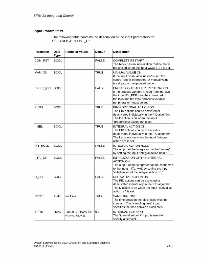
SFBs for Integrated Control
System Software for S7-300/400 System and Standard FunctionsA5E00171234-01 24-5
Input Parameters
The following table contains the description of the input parameters forSFB 41/FB 41 "CONT_C."
Parameter DataType
Range of Values Default Description
COM_RST BOOL FALSE COMPLETE RESTARTThe block has an initialization routine that isprocessed when the input COM_RST is set.
MAN_ON BOOL TRUE MANUAL VALUE ONIf the input "manual value on" is set, thecontrol loop is interrupted. A manual valueis set as the manipulated value.
PVPER_ON BOOL FALSE PROCESS VARIABLE PERIPHERAL ONIf the process variable is read from the I/Os,the input PV_PER must be connected tothe I/Os and the input "process variableperipheral on" must be set.
P_SEL BOOL TRUE PROPORTIONAL ACTION ONThe PID actions can be activated ordeactivated individually in the PID algorithm.The P action is on when the input"proportional action on" is set.
I_SEL BOOL TRUE INTEGRAL ACTION ONThe PID actions can be activated ordeactivated individually in the PID algorithm.The I action is on when the input "integralaction on" is set.
INT_HOLD BOOL FALSE INTEGRAL ACTION HOLDThe output of the integrator can be "frozen"by setting the input "integral action hold."
I_ITL_ON BOOL FALSE INITIALIZATION OF THE INTEGRALACTION ONThe output of the integrator can be connectedto the input I_ITL_VAL by setting the input"initialization of the integral action on."
D_SEL BOOL FALSE DERIVATIVE ACTION ONThe PID actions can be activated ordeactivated individually in the PID algorithm.The D action is on when the input "derivativeaction on" is set.
CYCLE TIME >= 1 ms T#1s SAMPLING TIMEThe time between the block calls must beconstant. The "sampling time" inputspecifies the time between block calls.
SP_INT REAL -100.0 to +100.0 (%)or phys. value 1)
0.0 INTERNAL SETPOINTThe "internal setpoint" input is used tospecify a setpoint.
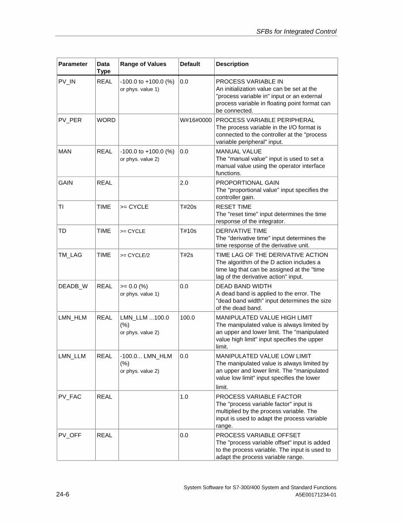
SFBs for Integrated Control
System Software for S7-300/400 System and Standard Functions24-6 A5E00171234-01
Parameter DataType
Range of Values Default Description
PV_IN REAL -100.0 to +100.0 (%)or phys. value 1)
0.0 PROCESS VARIABLE INAn initialization value can be set at the"process variable in" input or an externalprocess variable in floating point format canbe connected.
PV_PER WORD W#16#0000 PROCESS VARIABLE PERIPHERALThe process variable in the I/O format isconnected to the controller at the "processvariable peripheral" input.
MAN REAL -100.0 to +100.0 (%)or phys. value 2)
0.0 MANUAL VALUEThe "manual value" input is used to set amanual value using the operator interfacefunctions.
GAIN REAL 2.0 PROPORTIONAL GAINThe "proportional value" input specifies thecontroller gain.
TI TIME >= CYCLE T#20s RESET TIMEThe "reset time" input determines the timeresponse of the integrator.
TD TIME >= CYCLE T#10s DERIVATIVE TIMEThe "derivative time" input determines thetime response of the derivative unit.
TM_LAG TIME >= CYCLE/2 T#2s TIME LAG OF THE DERIVATIVE ACTIONThe algorithm of the D action includes atime lag that can be assigned at the "timelag of the derivative action" input.
DEADB_W REAL >= 0.0 (%)or phys. value 1)
0.0 DEAD BAND WIDTHA dead band is applied to the error. The"dead band width" input determines the sizeof the dead band.
LMN_HLM REAL LMN_LLM ...100.0(%)or phys. value 2)
100.0 MANIPULATED VALUE HIGH LIMITThe manipulated value is always limited byan upper and lower limit. The "manipulatedvalue high limit" input specifies the upperlimit.
LMN_LLM REAL -100.0... LMN_HLM(%)or phys. value 2)
0.0 MANIPULATED VALUE LOW LIMITThe manipulated value is always limited byan upper and lower limit. The "manipulatedvalue low limit" input specifies the lower
limit.
PV_FAC REAL 1.0 PROCESS VARIABLE FACTORThe "process variable factor" input ismultiplied by the process variable. Theinput is used to adapt the process variablerange.
PV_OFF REAL 0.0 PROCESS VARIABLE OFFSETThe "process variable offset" input is addedto the process variable. The input is used toadapt the process variable range.
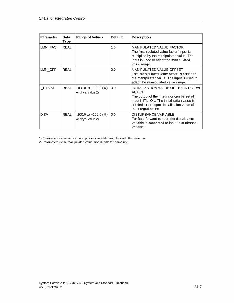
SFBs for Integrated Control
System Software for S7-300/400 System and Standard FunctionsA5E00171234-01 24-7
Parameter DataType
Range of Values Default Description
LMN_FAC REAL 1.0 MANIPULATED VALUE FACTORThe "manipulated value factor" input ismultiplied by the manipulated value. Theinput is used to adapt the manipulatedvalue range.
LMN_OFF REAL 0.0 MANIPULATED VALUE OFFSETThe "manipulated value offset" is added tothe manipulated value. The input is used toadapt the manipulated value range.
I_ITLVAL REAL -100.0 to +100.0 (%)or phys. value 2)
0.0 INITIALIZATION VALUE OF THE INTEGRALACTIONThe output of the integrator can be set atinput I_ITL_ON. The initialization value isapplied to the input "initialization value ofthe integral action."
DISV REAL -100.0 to +100.0 (%)or phys. value 2)
0.0 DISTURBANCE VARIABLEFor feed forward control, the disturbancevariable is connected to input "disturbancevariable."
1) Parameters in the setpoint and process variable branches with the same unit2) Parameters in the manipulated value branch with the same unit
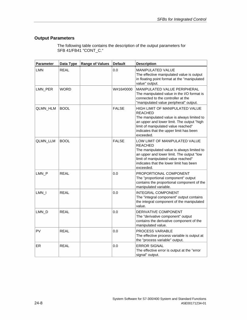
SFBs for Integrated Control
System Software for S7-300/400 System and Standard Functions24-8 A5E00171234-01
Output Parameters
The following table contains the description of the output parameters forSFB 41/FB41 "CONT_C."
Parameter Data Type Range of Values Default Description
LMN REAL 0.0 MANIPULATED VALUEThe effective manipulated value is outputin floating point format at the "manipulatedvalue" output.
LMN_PER WORD W#16#0000 MANIPULATED VALUE PERIPHERALThe manipulated value in the I/O format isconnected to the controller at the"manipulated value peripheral" output.
QLMN_HLM BOOL FALSE HIGH LIMIT OF MANIPULATED VALUEREACHEDThe manipulated value is always limited toan upper and lower limit. The output "highlimit of manipulated value reached"indicates that the upper limit has beenexceeded.
QLMN_LLM BOOL FALSE LOW LIMIT OF MANIPULATED VALUEREACHEDThe manipulated value is always limited toan upper and lower limit. The output "lowlimit of manipulated value reached"indicates that the lower limit has beenexceeded.
LMN_P REAL 0.0 PROPORTIONAL COMPONENTThe "proportional component" outputcontains the proportional component of themanipulated variable.
LMN_I REAL 0.0 INTEGRAL COMPONENTThe "integral component" output containsthe integral component of the manipulatedvalue.
LMN_D REAL 0.0 DERIVATIVE COMPONENTThe "derivative component" outputcontains the derivative component of themanipulated value.
PV REAL 0.0 PROCESS VARIABLEThe effective process variable is output atthe "process variable" output.
ER REAL 0.0 ERROR SIGNALThe effective error is output at the "errorsignal" output.
SFBs for Integrated Control
System Software for S7-300/400 System and Standard FunctionsA5E00171234-01 24-9
24.2 Step Control with SFB 42/FB 42 "CONT_S"
Introduction
SFB/FB "CONT_S" (step controller) is used on SIMATIC S7 programmable logiccontrollers to control technical processes with digital manipulated value outputsignals for integrating actuators. During parameter assignment, you can activate ordeactivate sub-functions of the PI step controller to adapt the controller to theprocess. You can easily do this by using the parameter assignment tool (Menupath: Start > Simatic > Step7 > Assign PID Control parameters). The onlineelectronic manual is found under Start > Simatic > Step7 > Assign PID ControlEnglish.
Application
You can use the controller as a PI fixed setpoint controller or in secondary controlloops in cascade, blending or ratio controllers, however not as the primarycontroller. The functions of the controller are based on the PI control algorithm ofthe sampling controller supplemented by the functions for generating the binaryoutput signal from the analog actuating signal.
The following applies starting with FB V1.5 or V1.1.0 of CPU 314 IFM:
With TI = T#0ms, the integral component of the controller can be disabled, thusallowing the block to be used as a proportional controller.
Since the controller works without any position feedback signal, the internallycalculated manipulated variable will not exactly match the signal control elementposition. An adjustment is made if the manipulated variable (ER * GAIN) isnegative. The controller then sets the output QLMNDN (manipulated value signallow) until LMNR_LS (lower limit of the position feedback signal) is set.
The controller can also be used as a secondary actuator in a controller cascade.The setpoint input SP_INT is used to assign the control element position. In thiscase the actual value input and the parameter TI (integration time) must be set tozero. An application example is temperature regulation by means of heat outputcontrol using pulse-pause control and cooling capacity control by means of a valve.In this case, to close the valve completely, the manipulated variable (ER * GAIN)should have a negative setting.
SFBs for Integrated Control
System Software for S7-300/400 System and Standard Functions24-10 A5E00171234-01
Description
Apart from the functions in the process value branch, the SFB implements acomplete PI controller with a digital manipulated value output and the option ofinfluencing the manipulated value manually. The step controller operates without aposition feedback signal.In the following you will find the description of the partial functions:
Setpoint Branch
The setpoint is entered in floating-point format at the SP_INT input.
Process Variable Branch
The process variable can be input in the peripheral (I/O) or floating-point format.The CRP_IN function converts the PV_PER peripheral value to a floating-pointformat of -100 to +100 % according to the following formula:
Output of CPR_IN = PV_PER *100
27648
The PV_NORM function normalizes the output of CRP_IN according to thefollowing formula:
Output of PV_NORM = (output of CPR_IN) * PV_FAC + PV_OFF
PV_FAC has a default of 1 and PV_OFF a default of 0.
Error Signal
The difference between the setpoint and process variable is the error signal. Tosuppress a small constant oscillation due to the manipulated variable quantization(for example, due to a limited resolution of the manipulated value by the actuatorvalve), a dead band is applied to the error signal (DEADBAND). If DEADB_W = 0,the dead band is switched off.
PI Step Algorithm
The SFB/FB operates without a position feedback signal. The I action of the PIalgorithm and the assumed position feedback signal are calculated in oneintegrator (INT) and compared with the remaining P action as a feedback value.The difference is applied to a three-step element (THREE_ST) and a pulsegenerator (PULSEOUT) that creates the pulses for the actuator. The switchingfrequency of the controller can be reduced by adapting the threshold on of thethree-step element.
Feed Forward Control
A disturbance variable can be fed forward at the DISV input.
Initialization
SFB/FB42 "CONT_S" has an initialization routine that is run through when the inputparameter COM_RST = TRUE is set.
All other outputs are set to their default values.
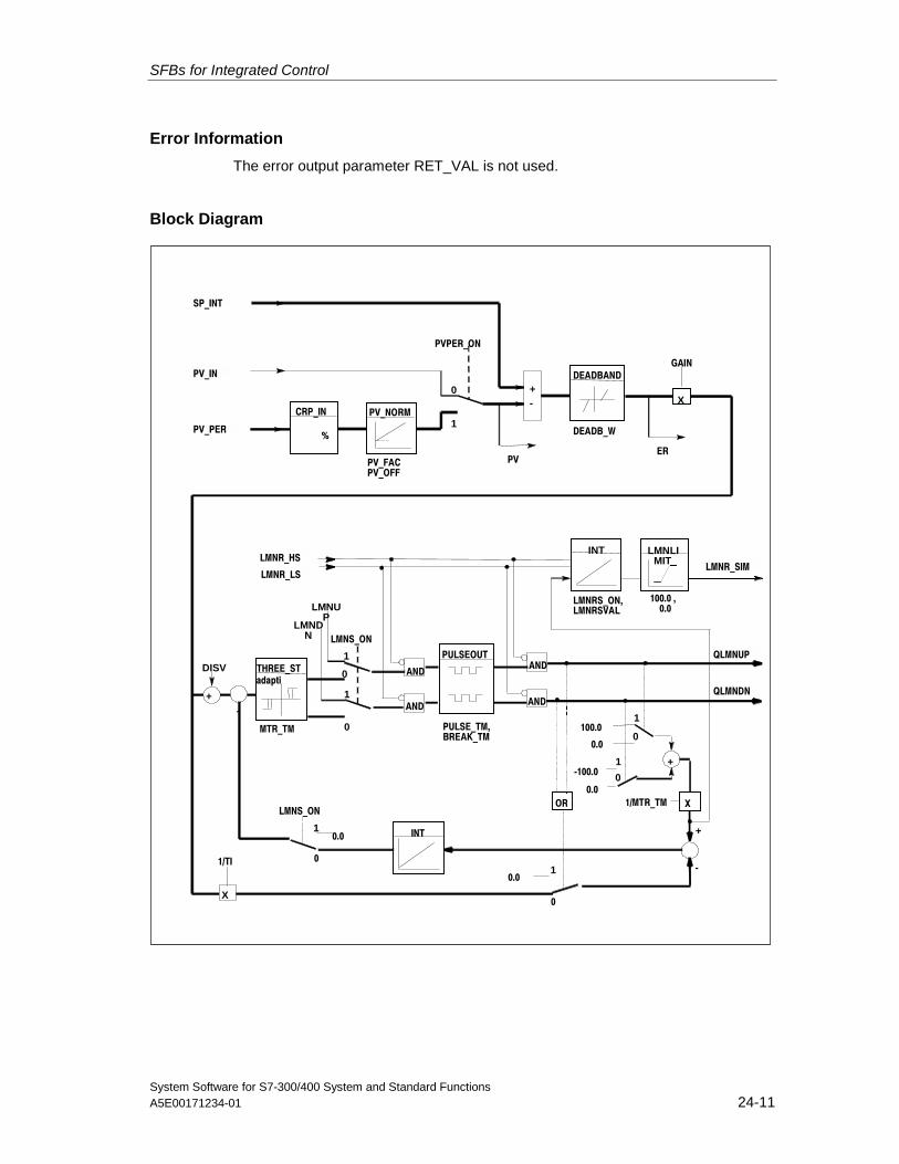
SFBs for Integrated Control
System Software for S7-300/400 System and Standard FunctionsA5E00171234-01 24-11
Error Information
The error output parameter RET_VAL is not used.
Block Diagram
+
PV_PER
SP_INT
CRP_IN
%
PV_NORM
DEADBANDPV_IN
PV_FACPV_OFF
PVPER_ON
-+
PV
DEADB_W
X
GAIN
ER
0
1
THREE_ST
INT
LMNR_SIM
LMNS_ON
LMNUP
LMNDN
PULSEOUT
AND
AND
AND
AND
LMNR_HS
LMNR_LS
QLMNDN
QLMNUP
100.0
0.0
-100.0
0.01/MTR_TM X
INT
LMNLIMIT
OR
10.0
+
-
0.0
LMNS_ON
0
1
0
1
0
0
1
1
0X
1/TI
1
0
+
DISV
-
adapti
LMNRS_ON,LMNRSVAL
100.0 , 0.0
MTR_TM PULSE_TM,BREAK_TM
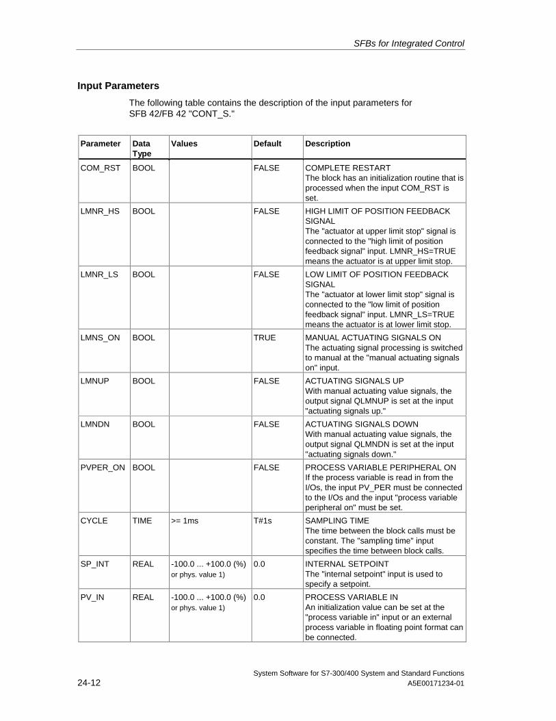
SFBs for Integrated Control
System Software for S7-300/400 System and Standard Functions24-12 A5E00171234-01
Input Parameters
The following table contains the description of the input parameters forSFB 42/FB 42 "CONT_S."
Parameter DataType
Values Default Description
COM_RST BOOL FALSE COMPLETE RESTARTThe block has an initialization routine that isprocessed when the input COM_RST isset.
LMNR_HS BOOL FALSE HIGH LIMIT OF POSITION FEEDBACKSIGNALThe "actuator at upper limit stop" signal isconnected to the "high limit of positionfeedback signal" input. LMNR_HS=TRUEmeans the actuator is at upper limit stop.
LMNR_LS BOOL FALSE LOW LIMIT OF POSITION FEEDBACKSIGNALThe "actuator at lower limit stop" signal isconnected to the "low limit of positionfeedback signal" input. LMNR_LS=TRUEmeans the actuator is at lower limit stop.
LMNS_ON BOOL TRUE MANUAL ACTUATING SIGNALS ONThe actuating signal processing is switchedto manual at the "manual actuating signalson" input.
LMNUP BOOL FALSE ACTUATING SIGNALS UPWith manual actuating value signals, theoutput signal QLMNUP is set at the input"actuating signals up."
LMNDN BOOL FALSE ACTUATING SIGNALS DOWNWith manual actuating value signals, theoutput signal QLMNDN is set at the input"actuating signals down."
PVPER_ON BOOL FALSE PROCESS VARIABLE PERIPHERAL ONIf the process variable is read in from theI/Os, the input PV_PER must be connectedto the I/Os and the input "process variableperipheral on" must be set.
CYCLE TIME >= 1ms T#1s SAMPLING TIMEThe time between the block calls must beconstant. The "sampling time" inputspecifies the time between block calls.
SP_INT REAL -100.0 ... +100.0 (%)or phys. value 1)
0.0 INTERNAL SETPOINTThe "internal setpoint" input is used tospecify a setpoint.
PV_IN REAL -100.0 ... +100.0 (%)or phys. value 1)
0.0 PROCESS VARIABLE INAn initialization value can be set at the"process variable in" input or an externalprocess variable in floating point format canbe connected.
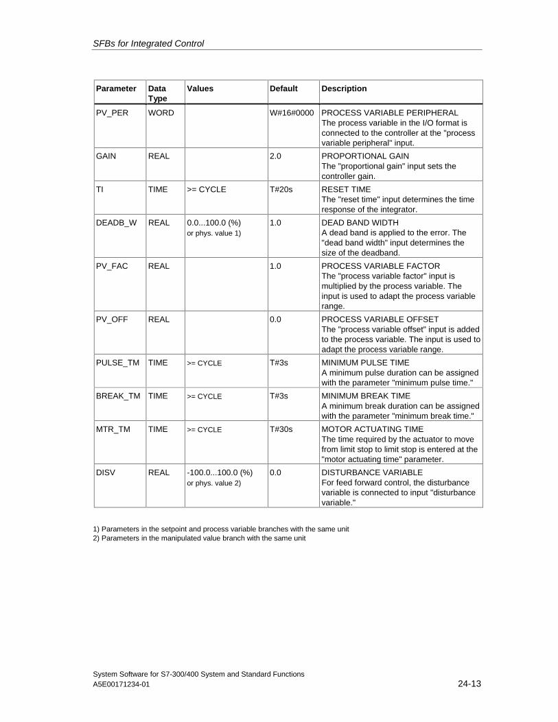
SFBs for Integrated Control
System Software for S7-300/400 System and Standard FunctionsA5E00171234-01 24-13
Parameter DataType
Values Default Description
PV_PER WORD W#16#0000 PROCESS VARIABLE PERIPHERALThe process variable in the I/O format isconnected to the controller at the "processvariable peripheral" input.
GAIN REAL 2.0 PROPORTIONAL GAINThe "proportional gain" input sets thecontroller gain.
TI TIME >= CYCLE T#20s RESET TIMEThe "reset time" input determines the timeresponse of the integrator.
DEADB_W REAL 0.0...100.0 (%)or phys. value 1)
1.0 DEAD BAND WIDTHA dead band is applied to the error. The"dead band width" input determines thesize of the deadband.
PV_FAC REAL 1.0 PROCESS VARIABLE FACTORThe "process variable factor" input ismultiplied by the process variable. Theinput is used to adapt the process variablerange.
PV_OFF REAL 0.0 PROCESS VARIABLE OFFSETThe "process variable offset" input is addedto the process variable. The input is used toadapt the process variable range.
PULSE_TM TIME >= CYCLE T#3s MINIMUM PULSE TIMEA minimum pulse duration can be assignedwith the parameter "minimum pulse time."
BREAK_TM TIME >= CYCLE T#3s MINIMUM BREAK TIMEA minimum break duration can be assignedwith the parameter "minimum break time."
MTR_TM TIME >= CYCLE T#30s MOTOR ACTUATING TIMEThe time required by the actuator to movefrom limit stop to limit stop is entered at the"motor actuating time" parameter.
DISV REAL -100.0...100.0 (%)or phys. value 2)
0.0 DISTURBANCE VARIABLEFor feed forward control, the disturbancevariable is connected to input "disturbancevariable."
1) Parameters in the setpoint and process variable branches with the same unit2) Parameters in the manipulated value branch with the same unit
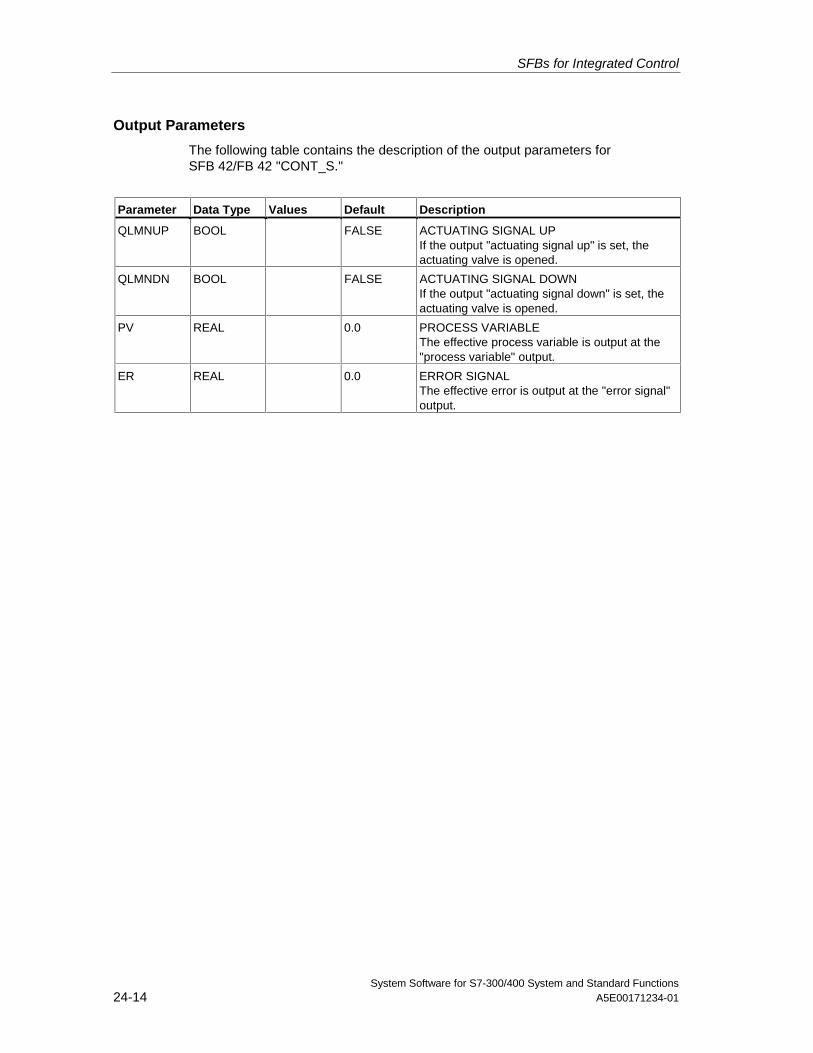
SFBs for Integrated Control
System Software for S7-300/400 System and Standard Functions24-14 A5E00171234-01
Output Parameters
The following table contains the description of the output parameters forSFB 42/FB 42 "CONT_S."
Parameter Data Type Values Default Description
QLMNUP BOOL FALSE ACTUATING SIGNAL UPIf the output "actuating signal up" is set, theactuating valve is opened.
QLMNDN BOOL FALSE ACTUATING SIGNAL DOWNIf the output "actuating signal down" is set, theactuating valve is opened.
PV REAL 0.0 PROCESS VARIABLEThe effective process variable is output at the"process variable" output.
ER REAL 0.0 ERROR SIGNALThe effective error is output at the "error signal"output.
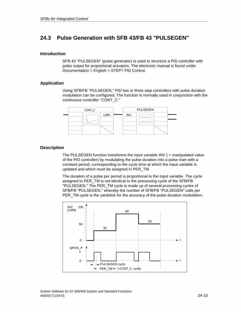
SFBs for Integrated Control
System Software for S7-300/400 System and Standard FunctionsA5E00171234-01 24-15
24.3 Pulse Generation with SFB 43/FB 43 "PULSEGEN"
Introduction
SFB 43 "PULSEGEN" (pulse generator) is used to structure a PID controller withpulse output for proportional actuators. The electronic manual is found underDocumentation > English > STEP7 PID Control.
Application
Using SFB/FB "PULSEGEN," PID two or three step controllers with pulse durationmodulation can be configured. The function is normally used in conjunction with thecontinuous controller "CONT_C."
LMN
PULSEGEN
INV
CONT_C
Description
The PULSEGEN function transforms the input variable INV ( = manipulated valueof the PID controller) by modulating the pulse duration into a pulse train with aconstant period, corresponding to the cycle time at which the input variable isupdated and which must be assigned in PER_TM.
The duration of a pulse per period is proportional to the input variable. The cycleassigned to PER_TM is not identical to the processing cycle of the SFB/FB"PULSEGEN." The PER_TM cycle is made up of several processing cycles ofSFB/FB "PULSEGEN," whereby the number of SFB/FB "PULSEGEN" calls perPER_TM cycle is the yardstick for the accuracy of the pulse duration modulation.
t
INV
QPOS_P
(LMN)
0
50
100
1
0 t
PER_TM
PULSEGEN cycle
30
50
80
(=CONT_C cycle)
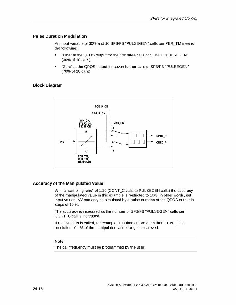
SFBs for Integrated Control
System Software for S7-300/400 System and Standard Functions24-16 A5E00171234-01
Pulse Duration Modulation
An input variable of 30% and 10 SFB/FB "PULSEGEN" calls per PER_TM meansthe following:
• "One" at the QPOS output for the first three calls of SFB/FB "PULSEGEN"(30% of 10 calls)
• "Zero" at the QPOS output for seven further calls of SFB/FB "PULSEGEN"(70% of 10 calls)
Block Diagram
#QPOS_P
QNEG_P
MAN_ON
NEG_P_ON
POS_P_ON
INV
SYN_ON,STEP3_ON,ST2BI_ON
PER_TM,P_B_TM,RATIOFAC
0
1
Accuracy of the Manipulated Value
With a "sampling ratio" of 1:10 (CONT_C calls to PULSEGEN calls) the accuracyof the manipulated value in this example is restricted to 10%, in other words, setinput values INV can only be simulated by a pulse duration at the QPOS output insteps of 10 %.
The accuracy is increased as the number of SFB/FB "PULSEGEN" calls perCONT_C call is increased.
If PULSEGEN is called, for example, 100 times more often than CONT_C, aresolution of 1 % of the manipulated value range is achieved.
Note
The call frequency must be programmed by the user.
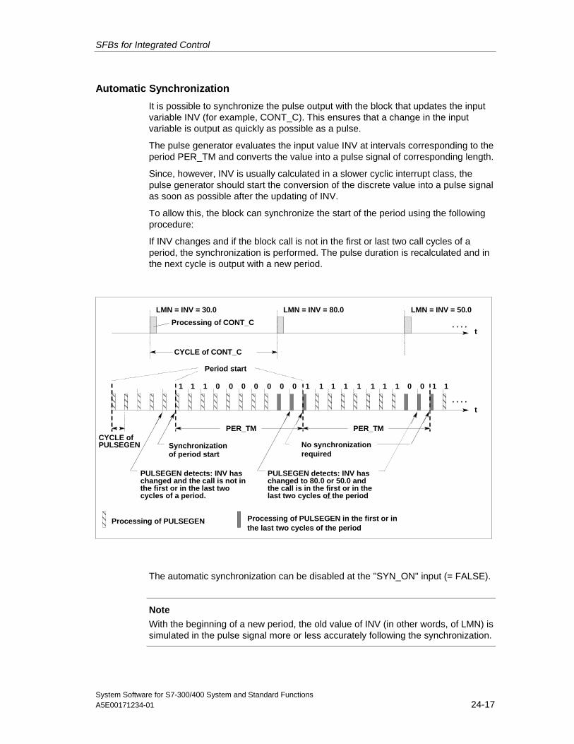
SFBs for Integrated Control
System Software for S7-300/400 System and Standard FunctionsA5E00171234-01 24-17
Automatic Synchronization
It is possible to synchronize the pulse output with the block that updates the inputvariable INV (for example, CONT_C). This ensures that a change in the inputvariable is output as quickly as possible as a pulse.
The pulse generator evaluates the input value INV at intervals corresponding to theperiod PER_TM and converts the value into a pulse signal of corresponding length.
Since, however, INV is usually calculated in a slower cyclic interrupt class, thepulse generator should start the conversion of the discrete value into a pulse signalas soon as possible after the updating of INV.
To allow this, the block can synchronize the start of the period using the followingprocedure:
If INV changes and if the block call is not in the first or last two call cycles of aperiod, the synchronization is performed. The pulse duration is recalculated and inthe next cycle is output with a new period.
CYCLE ofPULSEGEN
t
0
t
LMN = INV = 30.0 LMN = INV = 80.0 LMN = INV = 50.0
CYCLE of CONT_C
PER_TM PER_TM
00 0 01 1 0 0 11 1 11 1 1 11 0 0 11
. . . .
. . . .
Period start
Synchronizationof period start
PULSEGEN detects: INV haschanged and the call is not inthe first or in the last twocycles of a period.
PULSEGEN detects: INV haschanged to 80.0 or 50.0 andthe call is in the first or in thelast two cycles of the period
Processing of PULSEGEN Processing of PULSEGEN in the first or in
Processing of CONT_C
No synchronizationrequired
the last two cycles of the period
The automatic synchronization can be disabled at the "SYN_ON" input (= FALSE).
Note
With the beginning of a new period, the old value of INV (in other words, of LMN) issimulated in the pulse signal more or less accurately following the synchronization.
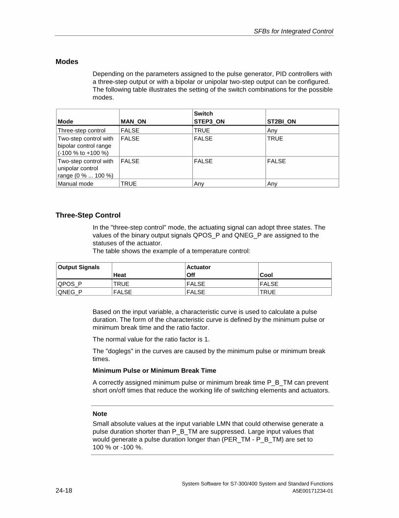
SFBs for Integrated Control
System Software for S7-300/400 System and Standard Functions24-18 A5E00171234-01
Modes
Depending on the parameters assigned to the pulse generator, PID controllers witha three-step output or with a bipolar or unipolar two-step output can be configured.The following table illustrates the setting of the switch combinations for the possiblemodes.
Switch Mode MAN_ON STEP3_ON ST2BI_ON
Three-step control FALSE TRUE AnyTwo-step control withbipolar control range(-100 % to +100 %)
FALSE FALSE TRUE
Two-step control withunipolar controlrange (0 % ... 100 %)
FALSE FALSE FALSE
Manual mode TRUE Any Any
Three-Step Control
In the "three-step control" mode, the actuating signal can adopt three states. Thevalues of the binary output signals QPOS_P and QNEG_P are assigned to thestatuses of the actuator.The table shows the example of a temperature control:
Output Signals Actuator Heat Off Cool
QPOS_P TRUE FALSE FALSEQNEG_P FALSE FALSE TRUE
Based on the input variable, a characteristic curve is used to calculate a pulseduration. The form of the characteristic curve is defined by the minimum pulse orminimum break time and the ratio factor.
The normal value for the ratio factor is 1.
The "doglegs" in the curves are caused by the minimum pulse or minimum breaktimes.
Minimum Pulse or Minimum Break Time
A correctly assigned minimum pulse or minimum break time P_B_TM can preventshort on/off times that reduce the working life of switching elements and actuators.
Note
Small absolute values at the input variable LMN that could otherwise generate apulse duration shorter than P_B_TM are suppressed. Large input values thatwould generate a pulse duration longer than (PER_TM - P_B_TM) are set to100 % or -100 %.
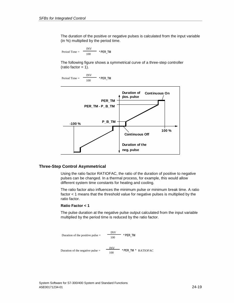
SFBs for Integrated Control
System Software for S7-300/400 System and Standard FunctionsA5E00171234-01 24-19
The duration of the positive or negative pulses is calculated from the input variable(in %) multiplied by the period time.
Period Time =100
INV* PER_TM
The following figure shows a symmetrical curve of a three-step controller(ratio factor = 1).
Period Time =100
INV* PER_TM
Duration ofthpos. pulse
-100 %
100 %
PER_TM
PER_TM - P_B_TM
P_B_TM
Continuous Off
Continuous On
Duration of the
neg. pulse
Three-Step Control Asymmetrical
Using the ratio factor RATIOFAC, the ratio of the duration of positive to negativepulses can be changed. In a thermal process, for example, this would allowdifferent system time constants for heating and cooling.
The ratio factor also influences the minimum pulse or minimum break time. A ratiofactor < 1 means that the threshold value for negative pulses is multiplied by theratio factor.
Ratio Factor < 1
The pulse duration at the negative pulse output calculated from the input variablemultiplied by the period time is reduced by the ratio factor.
Duration of the positive pulse =100
INV* PER_TM
Duration of the negative pulse =100
INV* PER_TM * RATIOFAC
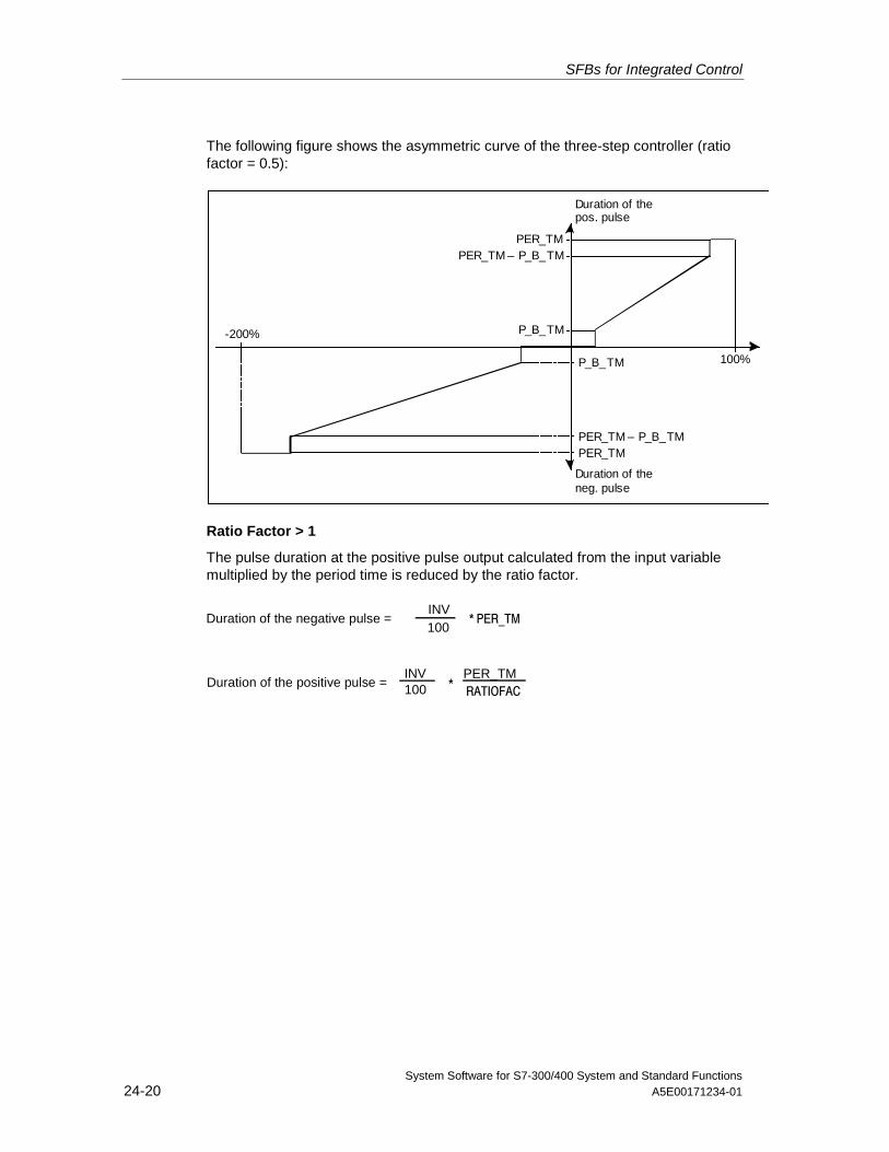
SFBs for Integrated Control
System Software for S7-300/400 System and Standard Functions24-20 A5E00171234-01
The following figure shows the asymmetric curve of the three-step controller (ratiofactor = 0.5):
100%
-200%
PER_TMPER_TM – P_B_TM
P_B_TM
PER_TMPER_TM – P_B_TM
P_B_TM
Duration of thepos. pulse
Duration of theneg. pulse
Ratio Factor > 1
The pulse duration at the positive pulse output calculated from the input variablemultiplied by the period time is reduced by the ratio factor.
Duration of the negative pulse =100INV
* PER_TM
INV PER_TM RATIOFAC
Duration of the positive pulse = 100 *
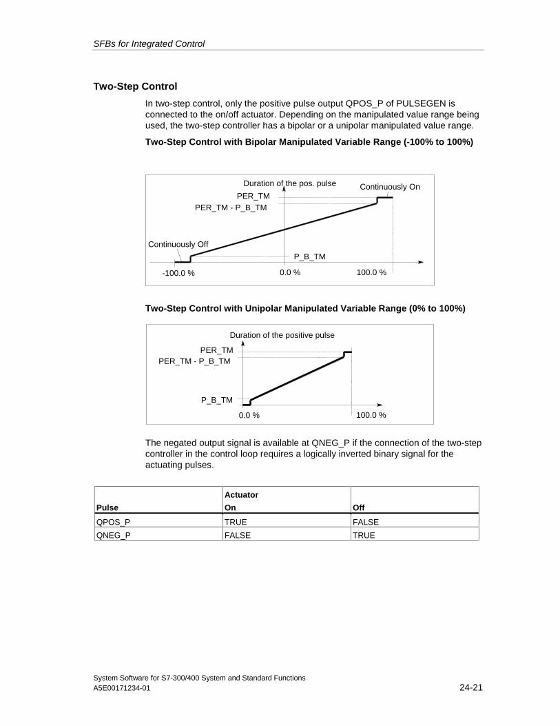
SFBs for Integrated Control
System Software for S7-300/400 System and Standard FunctionsA5E00171234-01 24-21
Two-Step Control
In two-step control, only the positive pulse output QPOS_P of PULSEGEN isconnected to the on/off actuator. Depending on the manipulated value range beingused, the two-step controller has a bipolar or a unipolar manipulated value range.
Two-Step Control with Bipolar Manipulated Variable Range (-100% to 100%)
Duration of the pos. pulse
-100.0 % 100.0 %
PER_TMPER_TM - P_B_TM
P_B_TM
Continuously Off
Continuously On
0.0 %
Two-Step Control with Unipolar Manipulated Variable Range (0% to 100%)
Duration of the positive pulse
100.0 %
PER_TMPER_TM - P_B_TM
P_B_TM
0.0 %
The negated output signal is available at QNEG_P if the connection of the two-stepcontroller in the control loop requires a logically inverted binary signal for theactuating pulses.
Actuator Pulse On Off
QPOS_P TRUE FALSE
QNEG_P FALSE TRUE
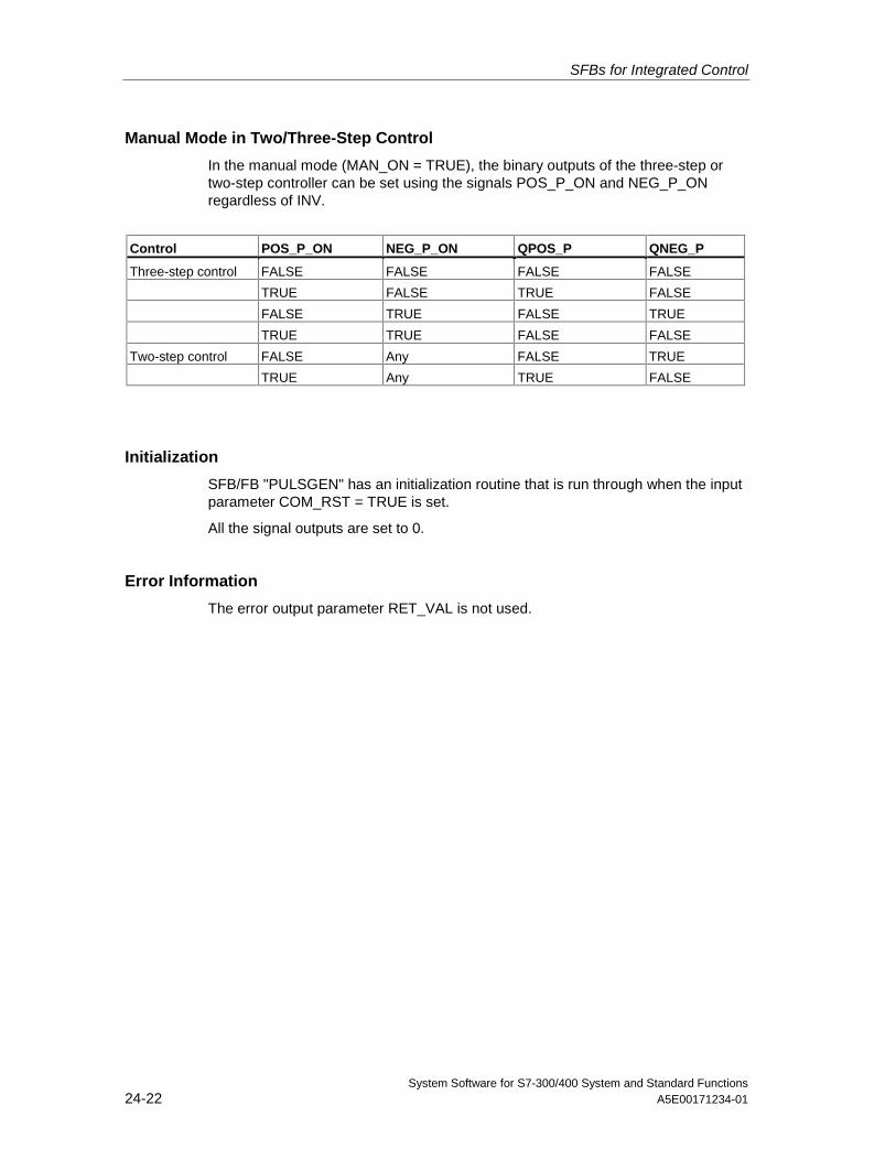
SFBs for Integrated Control
System Software for S7-300/400 System and Standard Functions24-22 A5E00171234-01
Manual Mode in Two/Three-Step Control
In the manual mode (MAN_ON = TRUE), the binary outputs of the three-step ortwo-step controller can be set using the signals POS_P_ON and NEG_P_ONregardless of INV.
Control POS_P_ON NEG_P_ON QPOS_P QNEG_P
Three-step control FALSE FALSE FALSE FALSE
TRUE FALSE TRUE FALSE
FALSE TRUE FALSE TRUE
TRUE TRUE FALSE FALSE
Two-step control FALSE Any FALSE TRUE
TRUE Any TRUE FALSE
Initialization
SFB/FB "PULSGEN" has an initialization routine that is run through when the inputparameter COM_RST = TRUE is set.
All the signal outputs are set to 0.
Error Information
The error output parameter RET_VAL is not used.
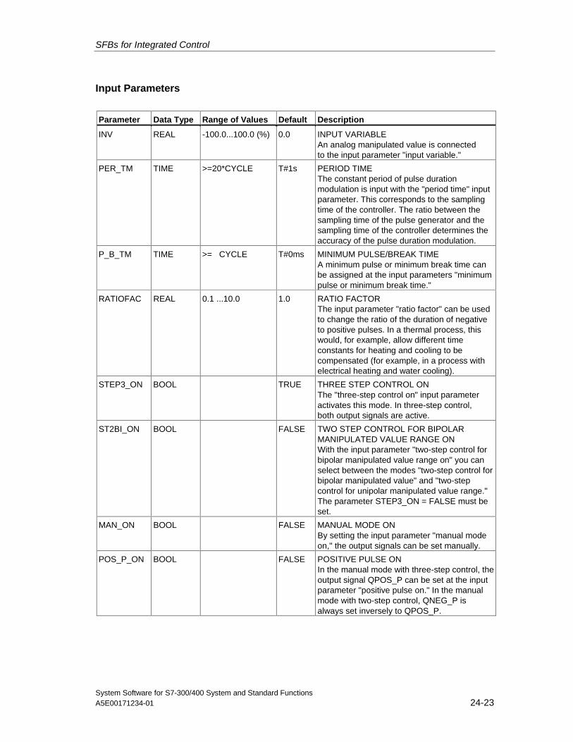
SFBs for Integrated Control
System Software for S7-300/400 System and Standard FunctionsA5E00171234-01 24-23
Input Parameters
Parameter Data Type Range of Values Default Description
INV REAL -100.0...100.0 (%) 0.0 INPUT VARIABLEAn analog manipulated value is connectedto the input parameter "input variable."
PER_TM TIME >=20*CYCLE T#1s PERIOD TIMEThe constant period of pulse durationmodulation is input with the "period time" inputparameter. This corresponds to the samplingtime of the controller. The ratio between thesampling time of the pulse generator and thesampling time of the controller determines theaccuracy of the pulse duration modulation.
P_B_TM TIME >= CYCLE T#0ms MINIMUM PULSE/BREAK TIMEA minimum pulse or minimum break time canbe assigned at the input parameters "minimumpulse or minimum break time."
RATIOFAC REAL 0.1 ...10.0 1.0 RATIO FACTORThe input parameter "ratio factor" can be usedto change the ratio of the duration of negativeto positive pulses. In a thermal process, thiswould, for example, allow different timeconstants for heating and cooling to becompensated (for example, in a process withelectrical heating and water cooling).
STEP3_ON BOOL TRUE THREE STEP CONTROL ONThe "three-step control on" input parameteractivates this mode. In three-step control,both output signals are active.
ST2BI_ON BOOL FALSE TWO STEP CONTROL FOR BIPOLARMANIPULATED VALUE RANGE ONWith the input parameter "two-step control forbipolar manipulated value range on" you canselect between the modes "two-step control forbipolar manipulated value" and "two-stepcontrol for unipolar manipulated value range."The parameter STEP3_ON = FALSE must beset.
MAN_ON BOOL FALSE MANUAL MODE ONBy setting the input parameter "manual modeon," the output signals can be set manually.
POS_P_ON BOOL FALSE POSITIVE PULSE ONIn the manual mode with three-step control, theoutput signal QPOS_P can be set at the inputparameter "positive pulse on." In the manualmode with two-step control, QNEG_P isalways set inversely to QPOS_P.
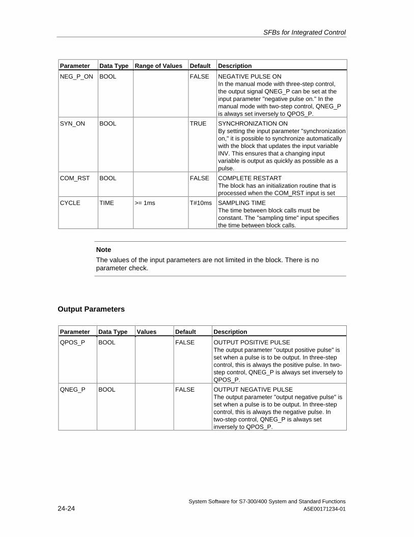
SFBs for Integrated Control
System Software for S7-300/400 System and Standard Functions24-24 A5E00171234-01
Parameter Data Type Range of Values Default Description
NEG_P_ON BOOL FALSE NEGATIVE PULSE ONIn the manual mode with three-step control,the output signal QNEG_P can be set at theinput parameter "negative pulse on." In themanual mode with two-step control, QNEG_Pis always set inversely to QPOS_P.
SYN_ON BOOL TRUE SYNCHRONIZATION ONBy setting the input parameter "synchronizationon," it is possible to synchronize automaticallywith the block that updates the input variableINV. This ensures that a changing inputvariable is output as quickly as possible as apulse.
COM_RST BOOL FALSE COMPLETE RESTARTThe block has an initialization routine that isprocessed when the COM_RST input is set
CYCLE TIME >= 1ms T#10ms SAMPLING TIMEThe time between block calls must beconstant. The "sampling time" input specifiesthe time between block calls.
Note
The values of the input parameters are not limited in the block. There is noparameter check.
Output Parameters
Parameter Data Type Values Default Description
QPOS_P BOOL FALSE OUTPUT POSITIVE PULSEThe output parameter "output positive pulse" isset when a pulse is to be output. In three-stepcontrol, this is always the positive pulse. In two-step control, QNEG_P is always set inversely toQPOS_P.
QNEG_P BOOL FALSE OUTPUT NEGATIVE PULSEThe output parameter "output negative pulse" isset when a pulse is to be output. In three-stepcontrol, this is always the negative pulse. Intwo-step control, QNEG_P is always setinversely to QPOS_P.
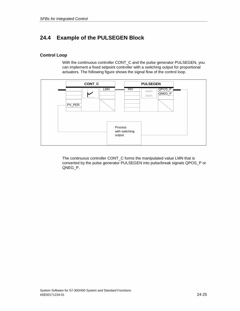
SFBs for Integrated Control
System Software for S7-300/400 System and Standard FunctionsA5E00171234-01 24-25
24.4 Example of the PULSEGEN Block
Control Loop
With the continuous controller CONT_C and the pulse generator PULSEGEN, youcan implement a fixed setpoint controller with a switching output for proportionalactuators. The following figure shows the signal flow of the control loop.
Processwith switchingoutput
PULSEGENCONT_CLMN
PV_PER
INV QPOS_PQNEG_P
The continuous controller CONT_C forms the manipulated value LMN that isconverted by the pulse generator PULSEGEN into pulse/break signals QPOS_P orQNEG_P.
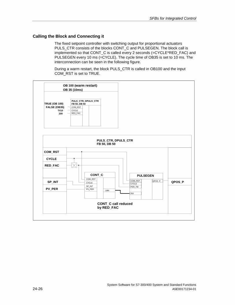
SFBs for Integrated Control
System Software for S7-300/400 System and Standard Functions24-26 A5E00171234-01
Calling the Block and Connecting it
The fixed setpoint controller with switching output for proportional actuatorsPULS_CTR consists of the blocks CONT_C and PULSEGEN. The block call isimplemented so that CONT_C is called every 2 seconds (=CYCLE*RED_FAC) andPULSEGEN every 10 ms (=CYCLE). The cycle time of OB35 is set to 10 ms. Theinterconnection can be seen in the following figure.
During a warm restart, the block PULS_CTR is called in OB100 and the inputCOM_RST is set to TRUE.
OB 100 (warm restart)OB 35 (10ms)
TRUE (OB 100)FALSE (OB35)
T#10200
PULS_CTR, DPULS_CTRFB 50, DB 50
PULS_CTR, DPULS_CTRFB 50, DB 50
COM_RST
CYCLERED_FAC
COM_RST
CYCLE
RED_FAC
SP_INT
PV_PER
COM_RST
CYCLE
COM_RST
CYCLE
PER_TM
INV
QPOS P
SP_INT
PV_PERLMN
QPOS_P
PULSEGENCONT_C
CONT_C call reducedby RED_FAC
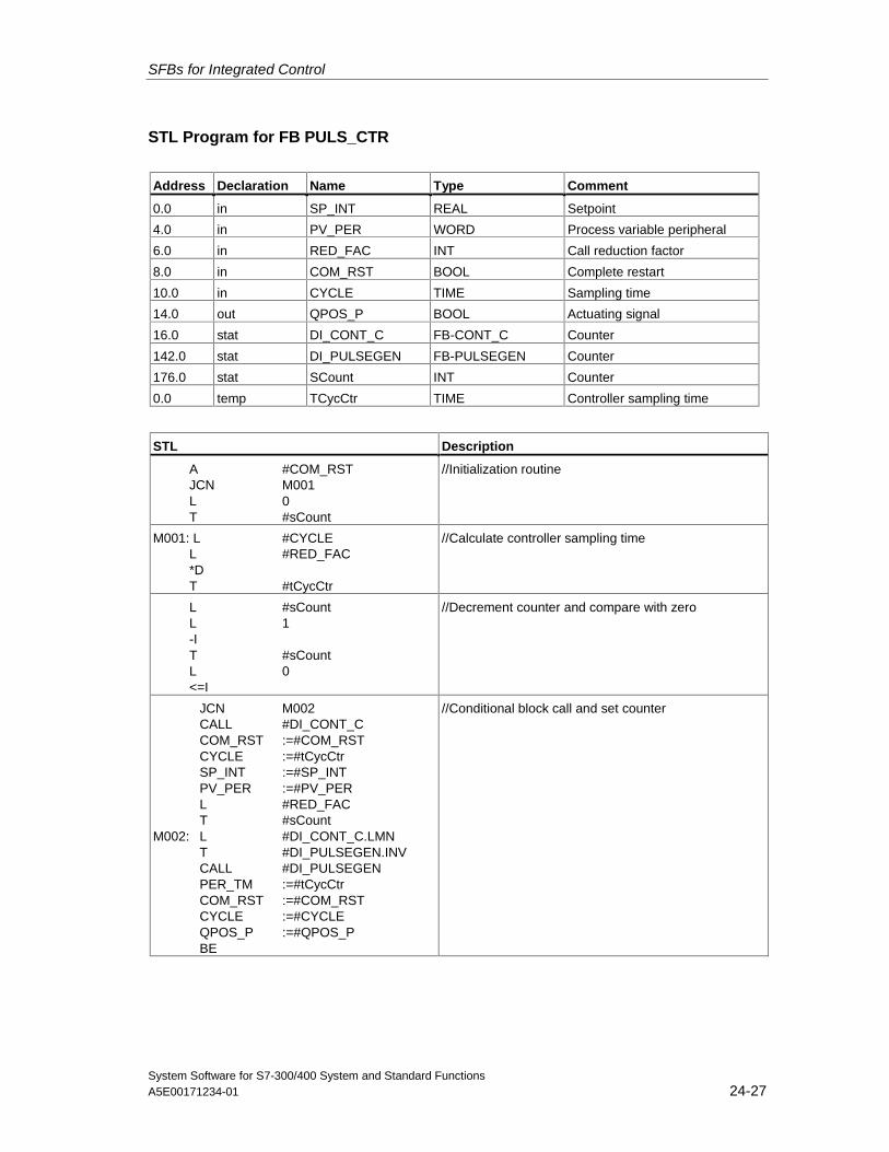
SFBs for Integrated Control
System Software for S7-300/400 System and Standard FunctionsA5E00171234-01 24-27
STL Program for FB PULS_CTR
Address Declaration Name Type Comment
0.0 in SP_INT REAL Setpoint
4.0 in PV_PER WORD Process variable peripheral
6.0 in RED_FAC INT Call reduction factor
8.0 in COM_RST BOOL Complete restart
10.0 in CYCLE TIME Sampling time
14.0 out QPOS_P BOOL Actuating signal
16.0 stat DI_CONT_C FB-CONT_C Counter
142.0 stat DI_PULSEGEN FB-PULSEGEN Counter
176.0 stat SCount INT Counter
0.0 temp TCycCtr TIME Controller sampling time
STL Description
A #COM_RSTJCN M001L 0T #sCount
//Initialization routine
M001: L #CYCLEL #RED_FAC*D T #tCycCtr
//Calculate controller sampling time
L #sCountL 1-IT #sCountL 0<=I
//Decrement counter and compare with zero
JCN M002CALL #DI_CONT_CCOM_RST :=#COM_RSTCYCLE :=#tCycCtrSP_INT :=#SP_INTPV_PER :=#PV_PERL #RED_FACT #sCount
M002: L #DI_CONT_C.LMNT #DI_PULSEGEN.INVCALL #DI_PULSEGENPER_TM :=#tCycCtrCOM_RST :=#COM_RSTCYCLE :=#CYCLEQPOS_P :=#QPOS_PBE
//Conditional block call and set counter

SFBs for Integrated Control
System Software for S7-300/400 System and Standard Functions24-28 A5E00171234-01
System Software for S7-300/400 System and Standard FunctionsA5E00171234-01 25-1
25 SFBs for Compact CPUs
25.1 Positioning With Analog Output Using SFB 44 "Analog"
Description
To control the positioning functions via the user program, use SFB ANALOG(SFB 44).
A fixed assigned analog output controls the power stage with a voltage (voltagesignal) of ±10 V or with a current (current signal) of ±20 mA.
• After the acceleration phase (RAM_UP) the drive approaches the target withthe speed (VSetpoint).
• At the braking point, that is calculated by the CPU, the deceleration(RAMP_DN) up to the change-over point is initialized.
• Once the change-over point is reached, run is continued with creep speed(VCreep).
• The drive is switched off at the cut-off point.
• The change-over point and the cut-off point are determined for every StepApproach in the parameter values change-over difference and cut-offdifference you have specified. The change-over difference and cut-offdifference can be determined differently for the forward motion (in plusdirection) and for the reverse motion (in minus direction).
• The run is completed (WORKING = FALSE) when the cut-off point is reached.A new run can then be started.
• The specified target is reached (POS_RCD = TRUE) when the actual positionvalue has reached the target range. If the actual position value drifts offwithout a new run having been started the "Position reached" signal is not resetagain.
When the change-over difference is smaller than the cut-off difference, the drive isslowed down as of the braking point to the speed setpoint 0.
Basic Parameters:
Here we describe the SFB parameters which apply to all operating modes. Theparameters specific to the operating mode are described with the individualoperating modes.
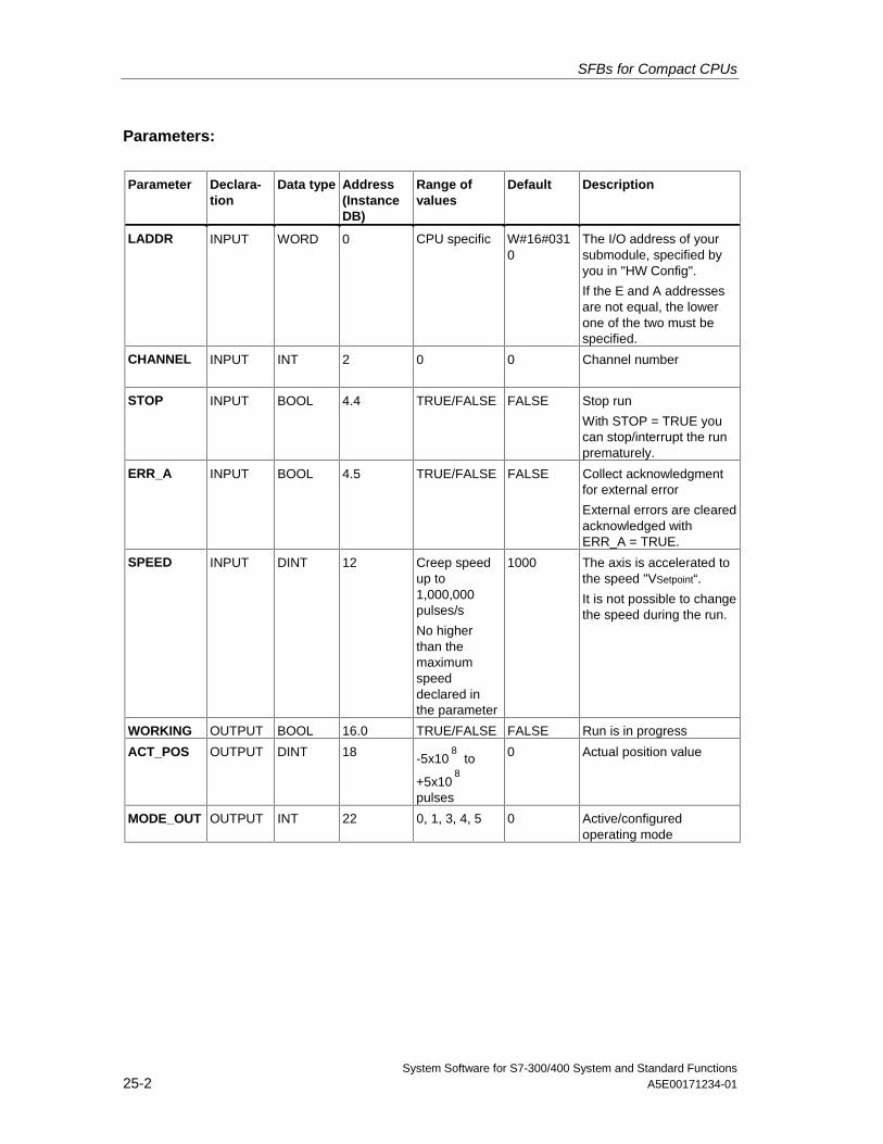
SFBs for Compact CPUs
System Software for S7-300/400 System and Standard Functions25-2 A5E00171234-01
Parameters:
Parameter Declara-tion
Data type Address(InstanceDB)
Range ofvalues
Default Description
LADDR INPUT WORD 0 CPU specific W#16#0310
The I/O address of yoursubmodule, specified byyou in "HW Config".
If the E and A addressesare not equal, the lowerone of the two must bespecified.
CHANNEL INPUT INT 2 0 0 Channel number
STOP INPUT BOOL 4.4 TRUE/FALSE FALSE Stop run
With STOP = TRUE youcan stop/interrupt the runprematurely.
ERR_A INPUT BOOL 4.5 TRUE/FALSE FALSE Collect acknowledgmentfor external error
External errors are clearedacknowledged withERR_A = TRUE.
SPEED INPUT DINT 12 Creep speedup to1,000,000pulses/s
No higherthan themaximumspeeddeclared inthe parameter
1000 The axis is accelerated tothe speed "VSetpoint“.
It is not possible to changethe speed during the run.
WORKING OUTPUT BOOL 16.0 TRUE/FALSE FALSE Run is in progress
ACT_POS OUTPUT DINT 18 -5x10⁸
to
+5x10⁸
pulses
0 Actual position value
MODE_OUT OUTPUT INT 22 0, 1, 3, 4, 5 0 Active/configuredoperating mode
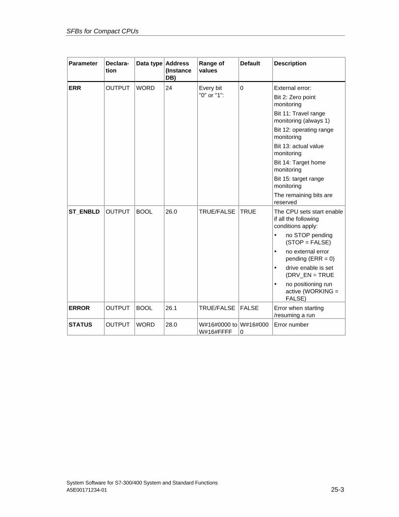
SFBs for Compact CPUs
System Software for S7-300/400 System and Standard FunctionsA5E00171234-01 25-3
Parameter Declara-tion
Data type Address(InstanceDB)
Range ofvalues
Default Description
ERR OUTPUT WORD 24 Every bit"0" or "1":
0 External error:
Bit 2: Zero pointmonitoring
Bit 11: Travel rangemonitoring (always 1)
Bit 12: operating rangemonitoring
Bit 13: actual valuemonitoring
Bit 14: Target homemonitoring
Bit 15: target rangemonitoring
The remaining bits arereserved
ST_ENBLD OUTPUT BOOL 26.0 TRUE/FALSE TRUE The CPU sets start enableif all the followingconditions apply:
• no STOP pending(STOP = FALSE)
• no external errorpending (ERR = 0)
• drive enable is set(DRV_EN = TRUE
• no positioning runactive (WORKING =FALSE)
ERROR OUTPUT BOOL 26.1 TRUE/FALSE FALSE Error when starting/resuming a run
STATUS OUTPUT WORD 28.0 W#16#0000 toW#16#FFFF
W#16#0000
Error number
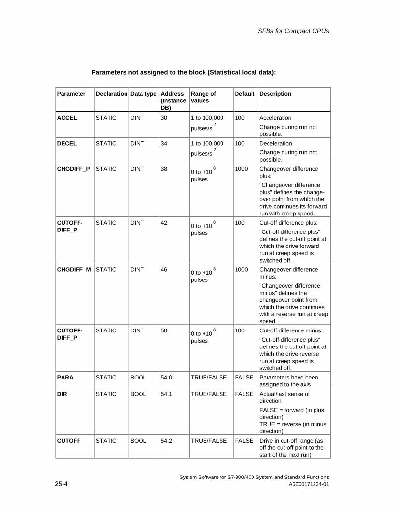
SFBs for Compact CPUs
System Software for S7-300/400 System and Standard Functions25-4 A5E00171234-01
Parameters not assigned to the block (Statistical local data):
Parameter Declaration Data type Address(InstanceDB)
Range ofvalues
Default Description
ACCEL STATIC DINT 30 1 to 100,000
pulses/s2
100 Acceleration
Change during run notpossible.
DECEL STATIC DINT 34 1 to 100,000
pulses/s2
100 Deceleration
Change during run notpossible.
CHGDIFF_P STATIC DINT 38 0 to +108
pulses
1000 Changeover differenceplus:
"Changeover differenceplus" defines the change-over point from which thedrive continues its forwardrun with creep speed.
CUTOFF-DIFF_P
STATIC DINT 42 0 to +108
pulses
100 Cut-off difference plus:
"Cut-off difference plus"defines the cut-off point atwhich the drive forwardrun at creep speed isswitched off.
CHGDIFF_M STATIC DINT 46 0 to +108
pulses
1000 Changeover differenceminus:
"Changeover differenceminus" defines thechangeover point fromwhich the drive continueswith a reverse run at creepspeed.
CUTOFF-DIFF_P
STATIC DINT 50 0 to +108
pulses
100 Cut-off difference minus:
"Cut-off difference plus"defines the cut-off point atwhich the drive reverserun at creep speed isswitched off.
PARA STATIC BOOL 54.0 TRUE/FALSE FALSE Parameters have beenassigned to the axis
DIR STATIC BOOL 54.1 TRUE/FALSE FALSE Actual/last sense ofdirection
FALSE = forward (in plusdirection)TRUE = reverse (in minusdirection)
CUTOFF STATIC BOOL 54.2 TRUE/FALSE FALSE Drive in cut-off range (asoff the cut-off point to thestart of the next run)
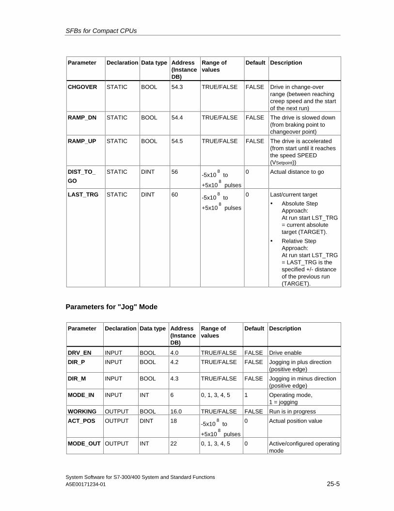
SFBs for Compact CPUs
System Software for S7-300/400 System and Standard FunctionsA5E00171234-01 25-5
Parameter Declaration Data type Address(InstanceDB)
Range ofvalues
Default Description
CHGOVER STATIC BOOL 54.3 TRUE/FALSE FALSE Drive in change-overrange (between reachingcreep speed and the startof the next run)
RAMP_DN STATIC BOOL 54.4 TRUE/FALSE FALSE The drive is slowed down(from braking point tochangeover point)
RAMP_UP STATIC BOOL 54.5 TRUE/FALSE FALSE The drive is accelerated(from start until it reachesthe speed SPEED(VSetpoint))
DIST_TO_
GO
STATIC DINT 56 -5x10⁸
to
+5x10⁸
pulses
0 Actual distance to go
LAST_TRG STATIC DINT 60 -5x10⁸
to
+5x10⁸
pulses
0 Last/current target
• Absolute StepApproach:At run start LST_TRG= current absolutetarget (TARGET).
• Relative StepApproach:At run start LST_TRG= LAST_TRG is thespecified +/- distanceof the previous run(TARGET).
Parameters for "Jog" Mode
Parameter Declaration Data type Address(InstanceDB)
Range ofvalues
Default Description
DRV_EN INPUT BOOL 4.0 TRUE/FALSE FALSE Drive enable
DIR_P INPUT BOOL 4.2 TRUE/FALSE FALSE Jogging in plus direction(positive edge)
DIR_M INPUT BOOL 4.3 TRUE/FALSE FALSE Jogging in minus direction(positive edge)
MODE_IN INPUT INT 6 0, 1, 3, 4, 5 1 Operating mode,1 = jogging
WORKING OUTPUT BOOL 16.0 TRUE/FALSE FALSE Run is in progress
ACT_POS OUTPUT DINT 18 -5x10⁸
to
+5x10⁸
pulses
0 Actual position value
MODE_OUT OUTPUT INT 22 0, 1, 3, 4, 5 0 Active/configured operatingmode
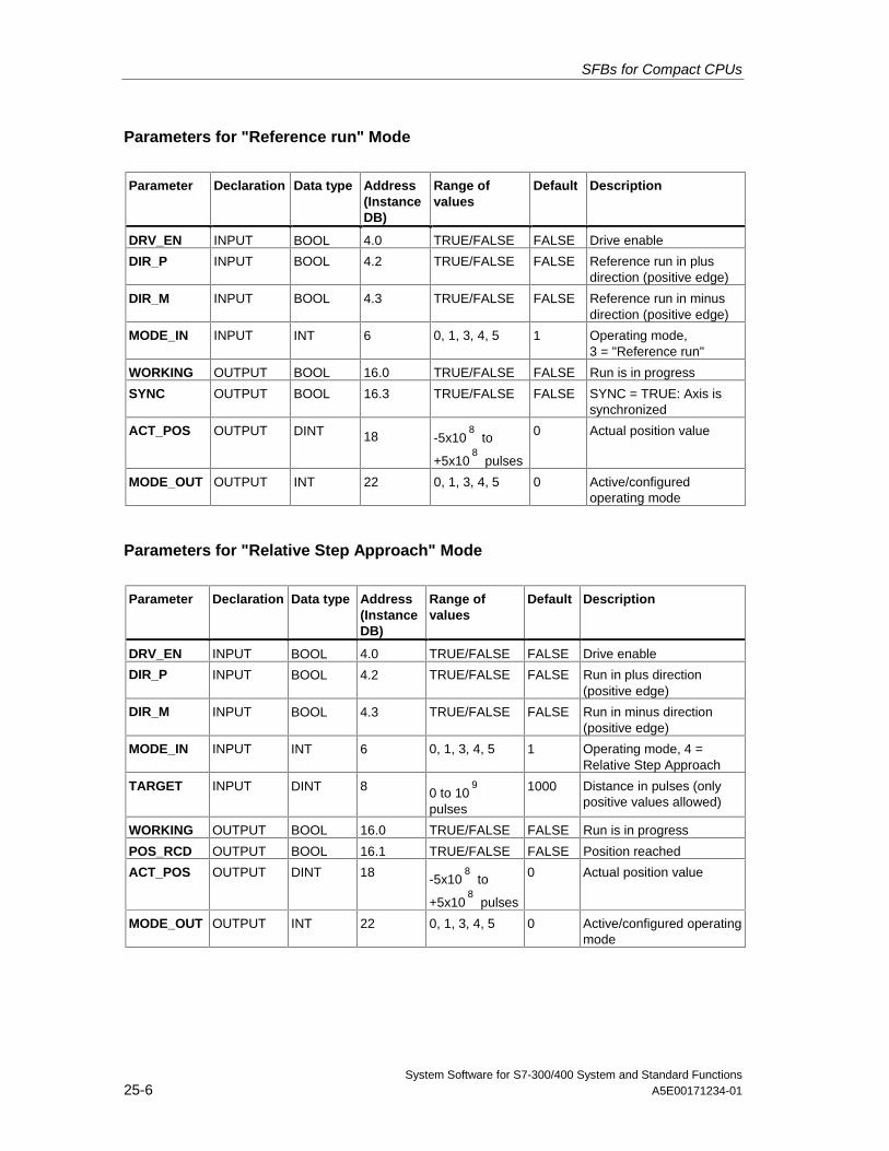
SFBs for Compact CPUs
System Software for S7-300/400 System and Standard Functions25-6 A5E00171234-01
Parameters for "Reference run" Mode
Parameter Declaration Data type Address(InstanceDB)
Range ofvalues
Default Description
DRV_EN INPUT BOOL 4.0 TRUE/FALSE FALSE Drive enable
DIR_P INPUT BOOL 4.2 TRUE/FALSE FALSE Reference run in plusdirection (positive edge)
DIR_M INPUT BOOL 4.3 TRUE/FALSE FALSE Reference run in minusdirection (positive edge)
MODE_IN INPUT INT 6 0, 1, 3, 4, 5 1 Operating mode,3 = "Reference run"
WORKING OUTPUT BOOL 16.0 TRUE/FALSE FALSE Run is in progress
SYNC OUTPUT BOOL 16.3 TRUE/FALSE FALSE SYNC = TRUE: Axis issynchronized
ACT_POS OUTPUT DINT 18 -5x10⁸
to
+5x10⁸
pulses
0 Actual position value
MODE_OUT OUTPUT INT 22 0, 1, 3, 4, 5 0 Active/configuredoperating mode
Parameters for "Relative Step Approach" Mode
Parameter Declaration Data type Address(InstanceDB)
Range ofvalues
Default Description
DRV_EN INPUT BOOL 4.0 TRUE/FALSE FALSE Drive enable
DIR_P INPUT BOOL 4.2 TRUE/FALSE FALSE Run in plus direction(positive edge)
DIR_M INPUT BOOL 4.3 TRUE/FALSE FALSE Run in minus direction(positive edge)
MODE_IN INPUT INT 6 0, 1, 3, 4, 5 1 Operating mode, 4 =Relative Step Approach
TARGET INPUT DINT 8 0 to 109
pulses
1000 Distance in pulses (onlypositive values allowed)
WORKING OUTPUT BOOL 16.0 TRUE/FALSE FALSE Run is in progress
POS_RCD OUTPUT BOOL 16.1 TRUE/FALSE FALSE Position reached
ACT_POS OUTPUT DINT 18 -5x10⁸
to
+5x10⁸
pulses
0 Actual position value
MODE_OUT OUTPUT INT 22 0, 1, 3, 4, 5 0 Active/configured operatingmode
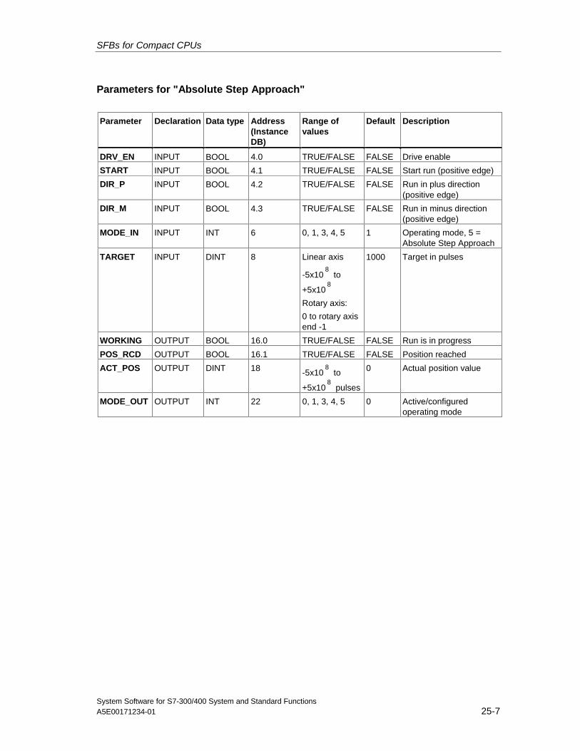
SFBs for Compact CPUs
System Software for S7-300/400 System and Standard FunctionsA5E00171234-01 25-7
Parameters for "Absolute Step Approach"
Parameter Declaration Data type Address(InstanceDB)
Range ofvalues
Default Description
DRV_EN INPUT BOOL 4.0 TRUE/FALSE FALSE Drive enable
START INPUT BOOL 4.1 TRUE/FALSE FALSE Start run (positive edge)
DIR_P INPUT BOOL 4.2 TRUE/FALSE FALSE Run in plus direction(positive edge)
DIR_M INPUT BOOL 4.3 TRUE/FALSE FALSE Run in minus direction(positive edge)
MODE_IN INPUT INT 6 0, 1, 3, 4, 5 1 Operating mode, 5 =Absolute Step Approach
TARGET INPUT DINT 8 Linear axis
-5x10⁸
to
+5x10⁸
Rotary axis:
0 to rotary axisend -1
1000 Target in pulses
WORKING OUTPUT BOOL 16.0 TRUE/FALSE FALSE Run is in progress
POS_RCD OUTPUT BOOL 16.1 TRUE/FALSE FALSE Position reached
ACT_POS OUTPUT DINT 18 -5x10⁸
to
+5x10⁸
pulses
0 Actual position value
MODE_OUT OUTPUT INT 22 0, 1, 3, 4, 5 0 Active/configuredoperating mode
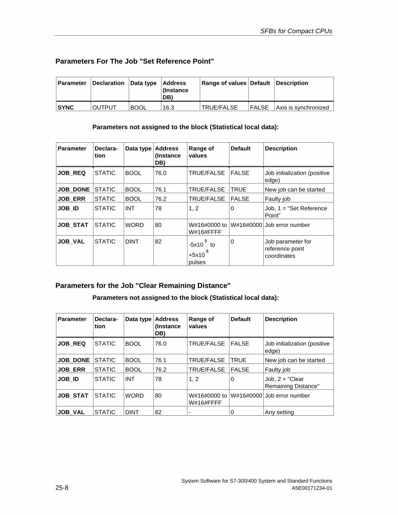
SFBs for Compact CPUs
System Software for S7-300/400 System and Standard Functions25-8 A5E00171234-01
Parameters For The Job "Set Reference Point"
Parameter Declaration Data type Address(InstanceDB)
Range of values Default Description
SYNC OUTPUT BOOL 16.3 TRUE/FALSE FALSE Axis is synchronized
Parameters not assigned to the block (Statistical local data):
Parameter Declara-tion
Data type Address(InstanceDB)
Range ofvalues
Default Description
JOB_REQ STATIC BOOL 76.0 TRUE/FALSE FALSE Job initialization (positiveedge)
JOB_DONE STATIC BOOL 76.1 TRUE/FALSE TRUE New job can be started
JOB_ERR STATIC BOOL 76.2 TRUE/FALSE FALSE Faulty job
JOB_ID STATIC INT 78 1, 2 0 Job, 1 = "Set ReferencePoint"
JOB_STAT STATIC WORD 80 W#16#0000 toW#16#FFFF
W#16#0000 Job error number
JOB_VAL STATIC DINT 82 -5x10⁸
to
+5x10⁸
pulses
0 Job parameter forreference pointcoordinates
Parameters for the Job "Clear Remaining Distance"
Parameters not assigned to the block (Statistical local data):
Parameter Declara-tion
Data type Address(InstanceDB)
Range ofvalues
Default Description
JOB_REQ STATIC BOOL 76.0 TRUE/FALSE FALSE Job initialization (positiveedge)
JOB_DONE STATIC BOOL 76.1 TRUE/FALSE TRUE New job can be started
JOB_ERR STATIC BOOL 76.2 TRUE/FALSE FALSE Faulty job
JOB_ID STATIC INT 78 1, 2 0 Job, 2 = "ClearRemaining Distance"
JOB_STAT STATIC WORD 80 W#16#0000 toW#16#FFFF
W#16#0000 Job error number
JOB_VAL STATIC DINT 82 - 0 Any setting
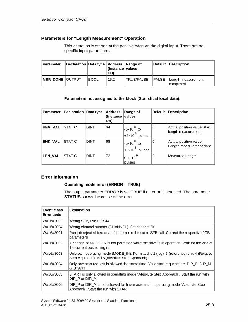
SFBs for Compact CPUs
System Software for S7-300/400 System and Standard FunctionsA5E00171234-01 25-9
Parameters for "Length Measurement" Operation
This operation is started at the positive edge on the digital input. There are nospecific input parameters.
Parameter Declaration Data type Address(InstanceDB)
Range ofvalues
Default Description
MSR_DONE OUTPUT BOOL 16.2 TRUE/FALSE FALSE Length measurementcompleted
Parameters not assigned to the block (Statistical local data):
Parameter Declaration Data type Address(InstanceDB)
Range ofvalues
Default Description
BEG_VAL STATIC DINT 64 -5x10⁸
to
+5x10⁸
pulses
0 Actual position value Startlength measurement
END_VAL STATIC DINT 68 -5x10⁸
to
+5x10⁸
pulses
0 Actual position valueLength measurement done
LEN_VAL STATIC DINT 72 0 to 109
pulses
0 Measured Length
Error Information
Operating mode error (ERROR = TRUE)
The output parameter ERROR is set TRUE if an error is detected. The parameterSTATUS shows the cause of the error.
Event classError code
Explanation
W#16#2002 Wrong SFB, use SFB 44
W#16#2004 Wrong channel number (CHANNEL). Set channel "0"
W#16#3001 Run job rejected because of job error in the same SFB call. Correct the respective JOBparameters
W#16#3002 A change of MODE_IN is not permitted while the drive is in operation. Wait for the end ofthe current positioning run.
W#16#3003 Unknown operating mode (MODE_IN). Permitted is 1 (jog), 3 (reference run), 4 (RelativeStep Approach) and 5 (absolute Step Approach).
W#16#3004 Only one start request is allowed the same time. Valid start requests are DIR_P, DIR_Mor START.
W#16#3005 START is only allowed in operating mode "Absolute Step Approach". Start the run withDIR_P or DIR_M
W#16#3006 DIR_P or DIR_M is not allowed for linear axis and in operating mode "Absolute StepApproach". Start the run with START
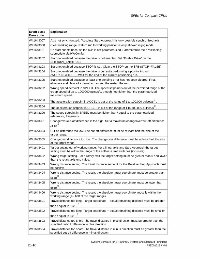
SFBs for Compact CPUs
System Software for S7-300/400 System and Standard Functions25-10 A5E00171234-01
Event classError code
Explanation
W#16#3007 Axis not synchronized. "Absolute Step Approach" is only possible synchronized axis.
W#16#3008 Clear working range. Return run to working position is only allowed in jog mode.
W#16#3101 No start enable because the axis is not parameterized. Parameterize the "Positioning"submodule via HWConfig
W#16#3102 Start not enabled because the drive is not enabled. Set "Enable Drive" on theSFB (DRV_EN=TRUE)
W#16#3103 Start not enabled because STOP is set. Clear the STOP on the SFB (STOP=FALSE)
W#16#3104 Start not enabled because the drive is currently performing a positioning run(WORKING=TRUE). Wait for the end of the current positioning run.
W#16#3105 Start not enabled because at least one pending error has not been cleared. First,eliminate and clear all external errors and the restart the run.
W#16#3202 Wrong speed setpoint in SPEED. The speed setpoint is out of the permitted range of thecreep speed of up to 1000000 pulses/s, though not higher than the parameterizedmaximum speed.
W#16#3203 The acceleration setpoint in ACCEL is out of the range of 1 to 100,000 pulses/s2
.
W#16#3204 The deceleration setpoint in DECEL is out of the range of 1 to 100,000 pulses/s2
.
W#16#3206 The speed setpoint in SPEED must be higher than / equal to the parameterizedreferencing frequency.
W#16#3301 Changeover/cut-off difference is too high. Set a maximum changeover/cut-off difference
of 108
W#16#3304 Cut-off difference too low. The cut-off difference must be at least half the size of thetarget range.
W#16#3305 Changeover difference too low. The changeover difference must be at least half the sizeof the target range.
W#16#3401 Target setting out of working range. For a linear axis and Step Approach the targetsetting must be within the range of the software limit switches (inclusive).
W#16#3402 Wrong target setting. For a rotary axis the target setting must be greater than 0 and lowerthan the rotary axis end value.
W#16#3403 Wrong distance setting. The travel distance setpoint for the Relative Step Approach mustbe positive.
W#16#3404 Wrong distance setting. The result, the absolute target coordinate, must be greater than -
5x10⁸
.
W#16#3405 Wrong distance setting. The result, the absolute target coordinate, must be lower than
5x10⁸
.
W#16#3406 Wrong distance setting. The result, the absolute target coordinate, must lie within theworking range (+/- half of the target range)
W#16#3501 Travel distance too long. Target coordinate + actual remaining distance must be greater
than / equal to -5x10⁸
W#16#3502 Travel distance too long. Target coordinate + actual remaining distance must be smaller
than / equal to 5x10⁸
W#16#3503 Travel distance too short. The travel distance in plus direction must be greater than thespecified cut-off difference in plus direction
W#16#3504 Travel distance too short. The travel distance in minus direction must be greater than thespecified cut-off difference in minus direction
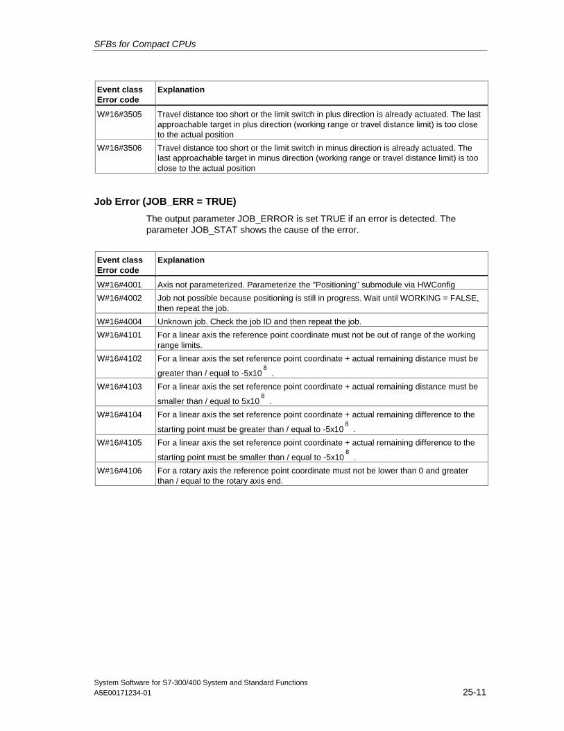
SFBs for Compact CPUs
System Software for S7-300/400 System and Standard FunctionsA5E00171234-01 25-11
Event classError code
Explanation
W#16#3505 Travel distance too short or the limit switch in plus direction is already actuated. The lastapproachable target in plus direction (working range or travel distance limit) is too closeto the actual position
W#16#3506 Travel distance too short or the limit switch in minus direction is already actuated. Thelast approachable target in minus direction (working range or travel distance limit) is tooclose to the actual position
Job Error (JOB_ERR = TRUE)
The output parameter JOB_ERROR is set TRUE if an error is detected. Theparameter JOB_STAT shows the cause of the error.
Event classError code
Explanation
W#16#4001 Axis not parameterized. Parameterize the "Positioning" submodule via HWConfig
W#16#4002 Job not possible because positioning is still in progress. Wait until WORKING = FALSE,then repeat the job.
W#16#4004 Unknown job. Check the job ID and then repeat the job.
W#16#4101 For a linear axis the reference point coordinate must not be out of range of the workingrange limits.
W#16#4102 For a linear axis the set reference point coordinate + actual remaining distance must be
greater than / equal to -5x10⁸
.
W#16#4103 For a linear axis the set reference point coordinate + actual remaining distance must be
smaller than / equal to 5x10⁸
.
W#16#4104 For a linear axis the set reference point coordinate + actual remaining difference to the
starting point must be greater than / equal to -5x10⁸
.
W#16#4105 For a linear axis the set reference point coordinate + actual remaining difference to the
starting point must be smaller than / equal to -5x10⁸
.
W#16#4106 For a rotary axis the reference point coordinate must not be lower than 0 and greaterthan / equal to the rotary axis end.
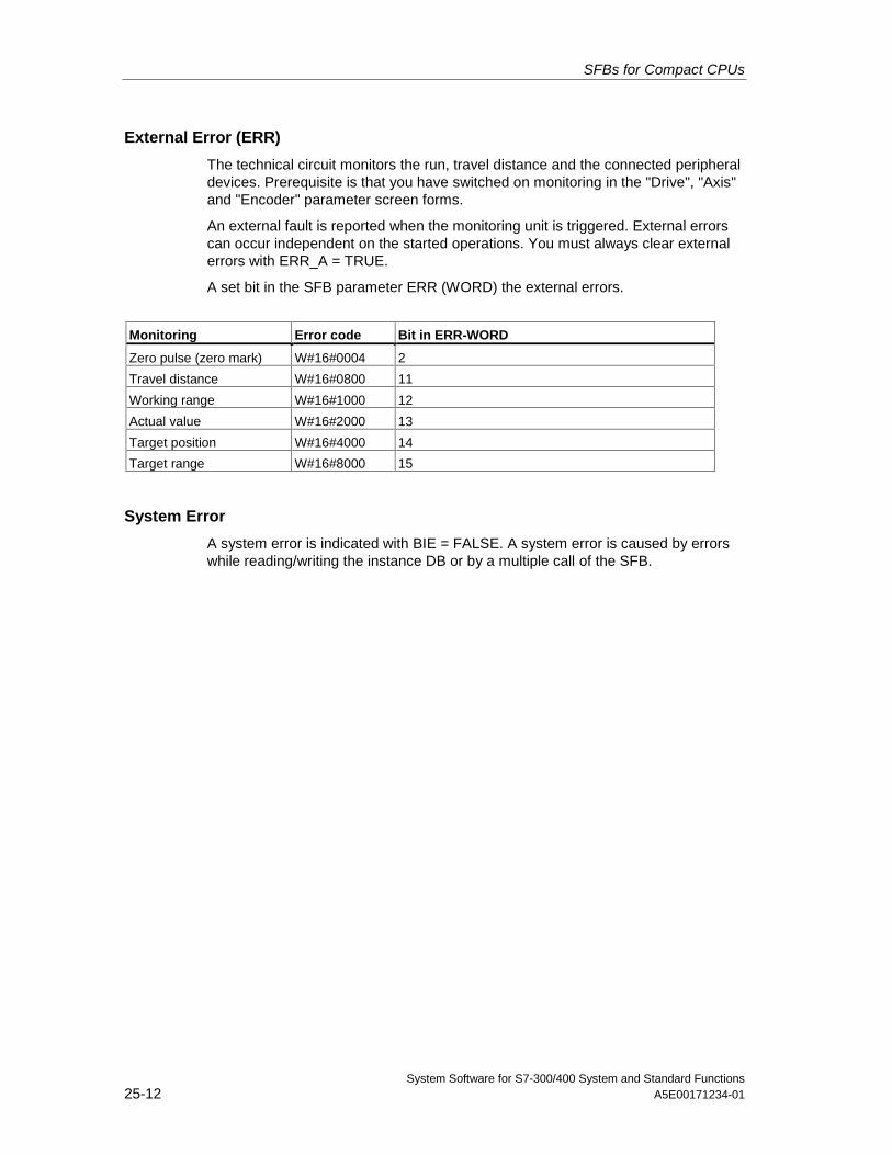
SFBs for Compact CPUs
System Software for S7-300/400 System and Standard Functions25-12 A5E00171234-01
External Error (ERR)
The technical circuit monitors the run, travel distance and the connected peripheraldevices. Prerequisite is that you have switched on monitoring in the "Drive", "Axis"and "Encoder" parameter screen forms.
An external fault is reported when the monitoring unit is triggered. External errorscan occur independent on the started operations. You must always clear externalerrors with ERR_A = TRUE.
A set bit in the SFB parameter ERR (WORD) the external errors.
Monitoring Error code Bit in ERR-WORD
Zero pulse (zero mark) W#16#0004 2
Travel distance W#16#0800 11
Working range W#16#1000 12
Actual value W#16#2000 13
Target position W#16#4000 14
Target range W#16#8000 15
System Error
A system error is indicated with BIE = FALSE. A system error is caused by errorswhile reading/writing the instance DB or by a multiple call of the SFB.
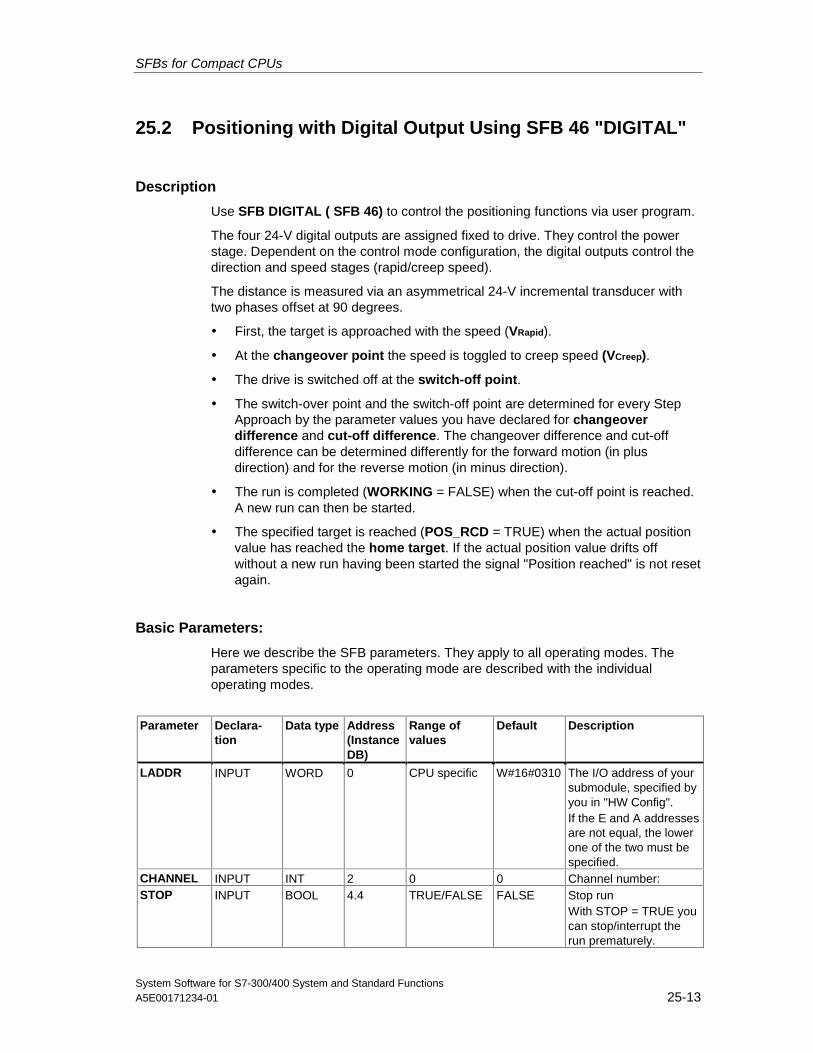
SFBs for Compact CPUs
System Software for S7-300/400 System and Standard FunctionsA5E00171234-01 25-13
25.2 Positioning with Digital Output Using SFB 46 "DIGITAL"
Description
Use SFB DIGITAL ( SFB 46) to control the positioning functions via user program.
The four 24-V digital outputs are assigned fixed to drive. They control the powerstage. Dependent on the control mode configuration, the digital outputs control thedirection and speed stages (rapid/creep speed).
The distance is measured via an asymmetrical 24-V incremental transducer withtwo phases offset at 90 degrees.
• First, the target is approached with the speed (VRapid).
• At the changeover point the speed is toggled to creep speed (VCreep).
• The drive is switched off at the switch-off point.
• The switch-over point and the switch-off point are determined for every StepApproach by the parameter values you have declared for changeoverdifference and cut-off difference. The changeover difference and cut-offdifference can be determined differently for the forward motion (in plusdirection) and for the reverse motion (in minus direction).
• The run is completed (WORKING = FALSE) when the cut-off point is reached.A new run can then be started.
• The specified target is reached (POS_RCD = TRUE) when the actual positionvalue has reached the home target. If the actual position value drifts offwithout a new run having been started the signal "Position reached" is not resetagain.
Basic Parameters:
Here we describe the SFB parameters. They apply to all operating modes. Theparameters specific to the operating mode are described with the individualoperating modes.
Parameter Declara-tion
Data type Address(InstanceDB)
Range ofvalues
Default Description
LADDR INPUT WORD 0 CPU specific W#16#0310 The I/O address of yoursubmodule, specified byyou in "HW Config".If the E and A addressesare not equal, the lowerone of the two must bespecified.
CHANNEL INPUT INT 2 0 0 Channel number:STOP INPUT BOOL 4.4 TRUE/FALSE FALSE Stop run
With STOP = TRUE youcan stop/interrupt therun prematurely.
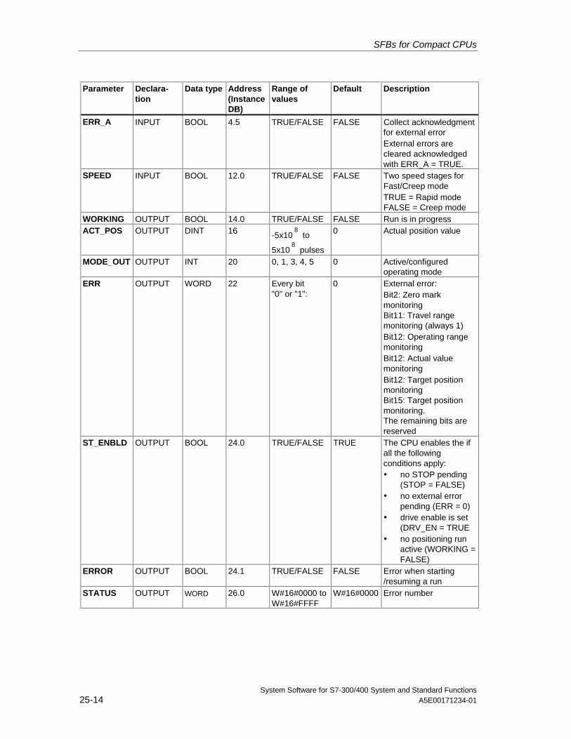
SFBs for Compact CPUs
System Software for S7-300/400 System and Standard Functions25-14 A5E00171234-01
Parameter Declara-tion
Data type Address(InstanceDB)
Range ofvalues
Default Description
ERR_A INPUT BOOL 4.5 TRUE/FALSE FALSE Collect acknowledgmentfor external errorExternal errors arecleared acknowledgedwith ERR_A = TRUE.
SPEED INPUT BOOL 12.0 TRUE/FALSE FALSE Two speed stages forFast/Creep modeTRUE = Rapid modeFALSE = Creep mode
WORKING OUTPUT BOOL 14.0 TRUE/FALSE FALSE Run is in progressACT_POS OUTPUT DINT 16 -5x10
8 to
5x10⁸
pulses
0 Actual position value
MODE_OUT OUTPUT INT 20 0, 1, 3, 4, 5 0 Active/configuredoperating mode
ERR OUTPUT WORD 22 Every bit"0" or "1":
0 External error:Bit2: Zero markmonitoringBit11: Travel rangemonitoring (always 1)Bit12: Operating rangemonitoringBit12: Actual valuemonitoringBit12: Target positionmonitoringBit15: Target positionmonitoring.The remaining bits arereserved
ST_ENBLD OUTPUT BOOL 24.0 TRUE/FALSE TRUE The CPU enables the ifall the followingconditions apply:• no STOP pending
(STOP = FALSE)• no external error
pending (ERR = 0)• drive enable is set
(DRV_EN = TRUE• no positioning run
active (WORKING =FALSE)
ERROR OUTPUT BOOL 24.1 TRUE/FALSE FALSE Error when starting/resuming a run
STATUS OUTPUT WORD 26.0 W#16#0000 toW#16#FFFF
W#16#0000 Error number
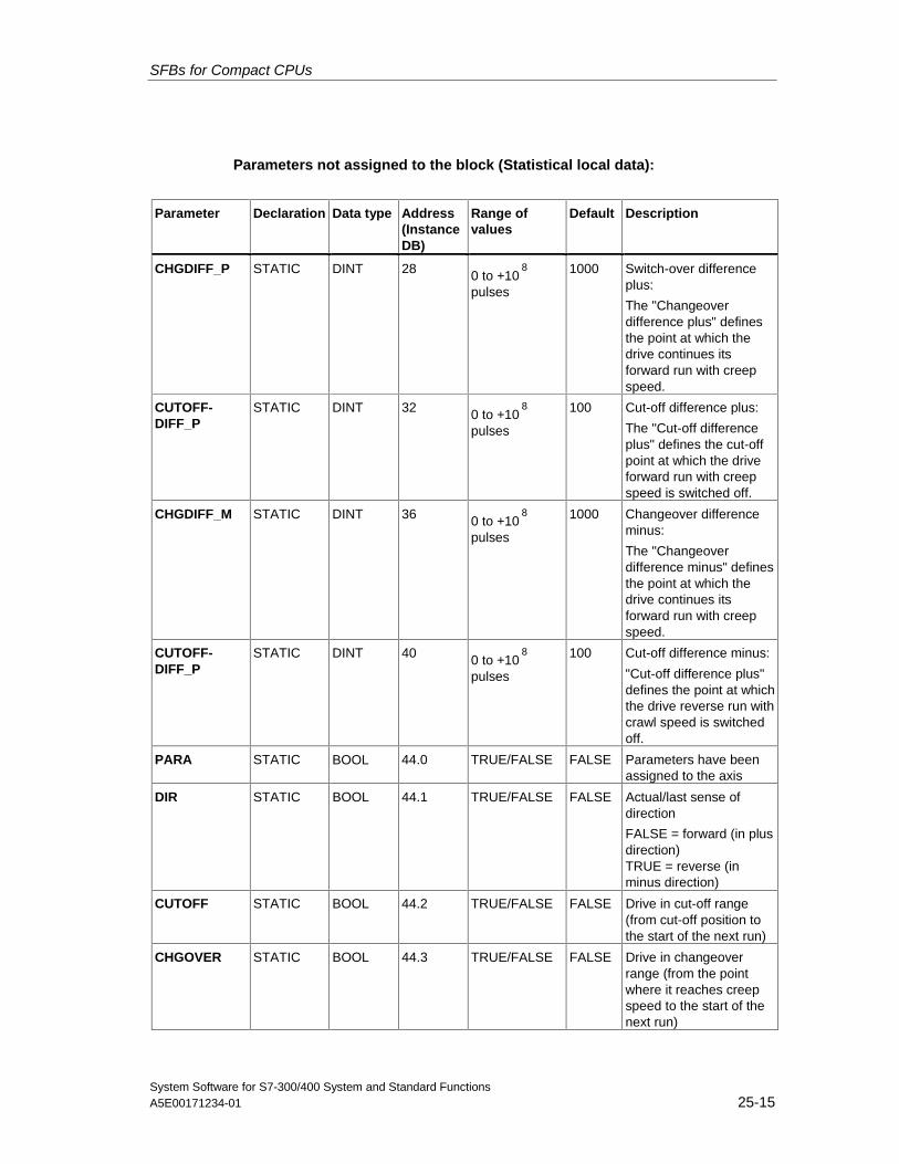
SFBs for Compact CPUs
System Software for S7-300/400 System and Standard FunctionsA5E00171234-01 25-15
Parameters not assigned to the block (Statistical local data):
Parameter Declaration Data type Address(InstanceDB)
Range ofvalues
Default Description
CHGDIFF_P STATIC DINT 28 0 to +108
pulses
1000 Switch-over differenceplus:
The "Changeoverdifference plus" definesthe point at which thedrive continues itsforward run with creepspeed.
CUTOFF-DIFF_P
STATIC DINT 32 0 to +108
pulses
100 Cut-off difference plus:
The "Cut-off differenceplus" defines the cut-offpoint at which the driveforward run with creepspeed is switched off.
CHGDIFF_M STATIC DINT 36 0 to +108
pulses
1000 Changeover differenceminus:
The "Changeoverdifference minus" definesthe point at which thedrive continues itsforward run with creepspeed.
CUTOFF-DIFF_P
STATIC DINT 40 0 to +108
pulses
100 Cut-off difference minus:
"Cut-off difference plus"defines the point at whichthe drive reverse run withcrawl speed is switchedoff.
PARA STATIC BOOL 44.0 TRUE/FALSE FALSE Parameters have beenassigned to the axis
DIR STATIC BOOL 44.1 TRUE/FALSE FALSE Actual/last sense ofdirection
FALSE = forward (in plusdirection)TRUE = reverse (inminus direction)
CUTOFF STATIC BOOL 44.2 TRUE/FALSE FALSE Drive in cut-off range(from cut-off position tothe start of the next run)
CHGOVER STATIC BOOL 44.3 TRUE/FALSE FALSE Drive in changeoverrange (from the pointwhere it reaches creepspeed to the start of thenext run)
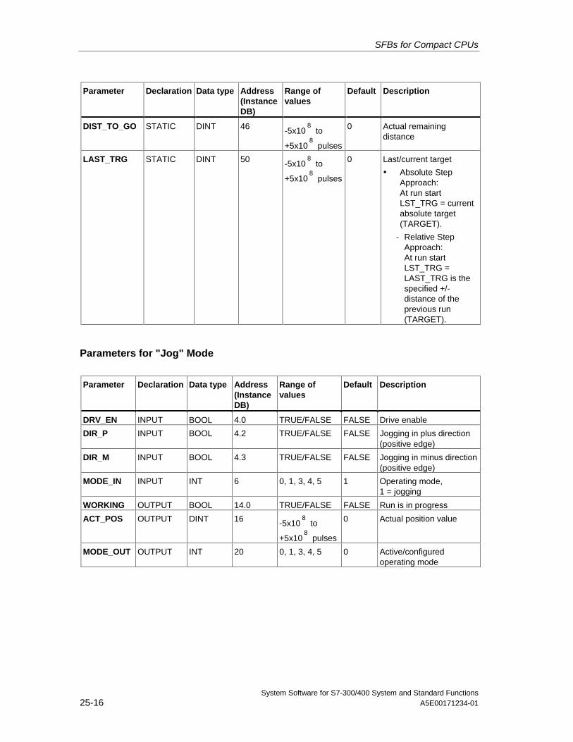
SFBs for Compact CPUs
System Software for S7-300/400 System and Standard Functions25-16 A5E00171234-01
Parameter Declaration Data type Address(InstanceDB)
Range ofvalues
Default Description
DIST_TO_GO STATIC DINT 46 -5x10⁸
to
+5x10⁸
pulses
0 Actual remainingdistance
LAST_TRG STATIC DINT 50 -5x10⁸
to
+5x10⁸
pulses
0 Last/current target
• Absolute StepApproach:At run startLST_TRG = currentabsolute target(TARGET).
- Relative StepApproach:At run startLST_TRG =LAST_TRG is thespecified +/-distance of theprevious run(TARGET).
Parameters for "Jog" Mode
Parameter Declaration Data type Address(InstanceDB)
Range ofvalues
Default Description
DRV_EN INPUT BOOL 4.0 TRUE/FALSE FALSE Drive enable
DIR_P INPUT BOOL 4.2 TRUE/FALSE FALSE Jogging in plus direction(positive edge)
DIR_M INPUT BOOL 4.3 TRUE/FALSE FALSE Jogging in minus direction(positive edge)
MODE_IN INPUT INT 6 0, 1, 3, 4, 5 1 Operating mode,1 = jogging
WORKING OUTPUT BOOL 14.0 TRUE/FALSE FALSE Run is in progress
ACT_POS OUTPUT DINT 16 -5x10⁸
to
+5x10⁸
pulses
0 Actual position value
MODE_OUT OUTPUT INT 20 0, 1, 3, 4, 5 0 Active/configuredoperating mode
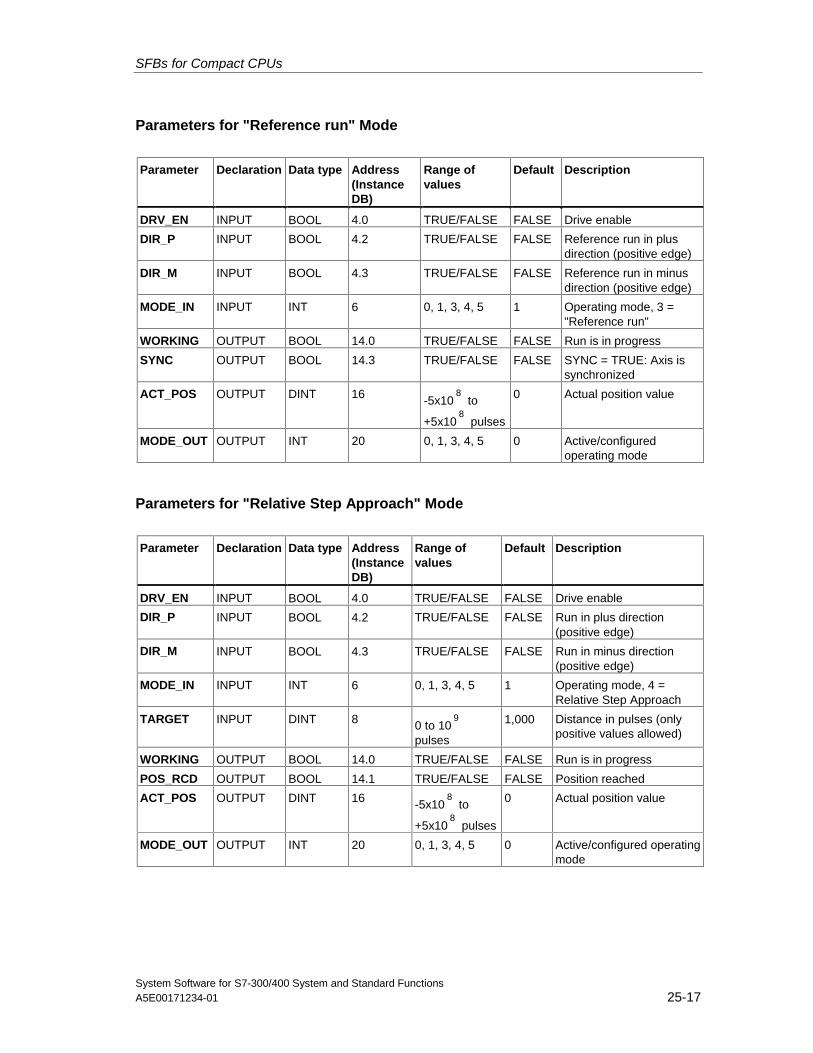
SFBs for Compact CPUs
System Software for S7-300/400 System and Standard FunctionsA5E00171234-01 25-17
Parameters for "Reference run" Mode
Parameter Declaration Data type Address(InstanceDB)
Range ofvalues
Default Description
DRV_EN INPUT BOOL 4.0 TRUE/FALSE FALSE Drive enable
DIR_P INPUT BOOL 4.2 TRUE/FALSE FALSE Reference run in plusdirection (positive edge)
DIR_M INPUT BOOL 4.3 TRUE/FALSE FALSE Reference run in minusdirection (positive edge)
MODE_IN INPUT INT 6 0, 1, 3, 4, 5 1 Operating mode, 3 ="Reference run"
WORKING OUTPUT BOOL 14.0 TRUE/FALSE FALSE Run is in progress
SYNC OUTPUT BOOL 14.3 TRUE/FALSE FALSE SYNC = TRUE: Axis issynchronized
ACT_POS OUTPUT DINT 16 -5x10⁸
to
+5x10⁸
pulses
0 Actual position value
MODE_OUT OUTPUT INT 20 0, 1, 3, 4, 5 0 Active/configuredoperating mode
Parameters for "Relative Step Approach" Mode
Parameter Declaration Data type Address(InstanceDB)
Range ofvalues
Default Description
DRV_EN INPUT BOOL 4.0 TRUE/FALSE FALSE Drive enable
DIR_P INPUT BOOL 4.2 TRUE/FALSE FALSE Run in plus direction(positive edge)
DIR_M INPUT BOOL 4.3 TRUE/FALSE FALSE Run in minus direction(positive edge)
MODE_IN INPUT INT 6 0, 1, 3, 4, 5 1 Operating mode, 4 =Relative Step Approach
TARGET INPUT DINT 8 0 to 109
pulses
1,000 Distance in pulses (onlypositive values allowed)
WORKING OUTPUT BOOL 14.0 TRUE/FALSE FALSE Run is in progress
POS_RCD OUTPUT BOOL 14.1 TRUE/FALSE FALSE Position reached
ACT_POS OUTPUT DINT 16 -5x10⁸
to
+5x10⁸
pulses
0 Actual position value
MODE_OUT OUTPUT INT 20 0, 1, 3, 4, 5 0 Active/configured operatingmode
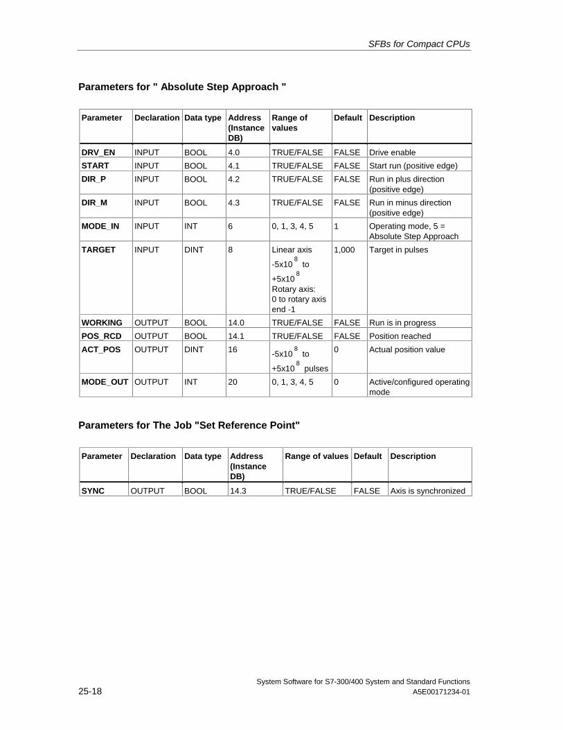
SFBs for Compact CPUs
System Software for S7-300/400 System and Standard Functions25-18 A5E00171234-01
Parameters for " Absolute Step Approach "
Parameter Declaration Data type Address(InstanceDB)
Range ofvalues
Default Description
DRV_EN INPUT BOOL 4.0 TRUE/FALSE FALSE Drive enable
START INPUT BOOL 4.1 TRUE/FALSE FALSE Start run (positive edge)
DIR_P INPUT BOOL 4.2 TRUE/FALSE FALSE Run in plus direction(positive edge)
DIR_M INPUT BOOL 4.3 TRUE/FALSE FALSE Run in minus direction(positive edge)
MODE_IN INPUT INT 6 0, 1, 3, 4, 5 1 Operating mode, 5 =Absolute Step Approach
TARGET INPUT DINT 8 Linear axis
-5x10⁸
to
+5x10⁸
Rotary axis:0 to rotary axisend -1
1,000 Target in pulses
WORKING OUTPUT BOOL 14.0 TRUE/FALSE FALSE Run is in progress
POS_RCD OUTPUT BOOL 14.1 TRUE/FALSE FALSE Position reached
ACT_POS OUTPUT DINT 16 -5x10⁸
to
+5x10⁸
pulses
0 Actual position value
MODE_OUT OUTPUT INT 20 0, 1, 3, 4, 5 0 Active/configured operatingmode
Parameters for The Job "Set Reference Point"
Parameter Declaration Data type Address(InstanceDB)
Range of values Default Description
SYNC OUTPUT BOOL 14.3 TRUE/FALSE FALSE Axis is synchronized
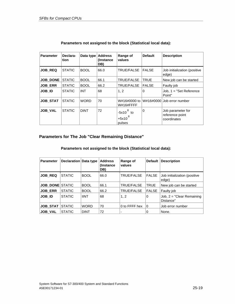
SFBs for Compact CPUs
System Software for S7-300/400 System and Standard FunctionsA5E00171234-01 25-19
Parameters not assigned to the block (Statistical local data):
Parameter Declara-tion
Data type Address(InstanceDB)
Range ofvalues
Default Description
JOB_REQ STATIC BOOL 66.0 TRUE/FALSE FALSE Job initialization (positiveedge)
JOB_DONE STATIC BOOL 66.1 TRUE/FALSE TRUE New job can be started
JOB_ERR STATIC BOOL 66.2 TRUE/FALSE FALSE Faulty job
JOB_ID STATIC INT 68 1, 2 0 Job, 1 = "Set ReferencePoint"
JOB_STAT STATIC WORD 70 W#16#0000 toW#16#FFFF
W#16#0000 Job error number
JOB_VAL STATIC DINT 72 -5x10⁸
to
+5x10⁸
pulses
0 Job parameter forreference pointcoordinates
Parameters for The Job "Clear Remaining Distance"
Parameters not assigned to the block (Statistical local data):
Parameter Declaration Data type Address(InstanceDB)
Range ofvalues
Default Description
JOB_REQ STATIC BOOL 66.0 TRUE/FALSE FALSE Job initialization (positiveedge)
JOB_DONE STATIC BOOL 66.1 TRUE/FALSE TRUE New job can be started
JOB_ERR STATIC BOOL 66.2 TRUE/FALSE FALSE Faulty job
JOB_ID STATIC IINT 68 1, 2 0 Job, 2 = "Clear RemainingDistance"
JOB_STAT STATIC WORD 70 0 to FFFF hex 0 Job error number
JOB_VAL STATIC DINT 72 - 0 None.
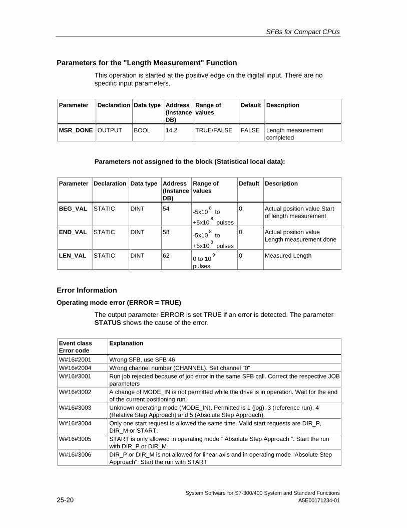
SFBs for Compact CPUs
System Software for S7-300/400 System and Standard Functions25-20 A5E00171234-01
Parameters for the "Length Measurement" Function
This operation is started at the positive edge on the digital input. There are nospecific input parameters.
Parameter Declaration Data type Address(InstanceDB)
Range ofvalues
Default Description
MSR_DONE OUTPUT BOOL 14.2 TRUE/FALSE FALSE Length measurementcompleted
Parameters not assigned to the block (Statistical local data):
Parameter Declaration Data type Address(InstanceDB)
Range ofvalues
Default Description
BEG_VAL STATIC DINT 54 -5x10⁸
to
+5x10⁸
pulses
0 Actual position value Startof length measurement
END_VAL STATIC DINT 58 -5x10⁸
to
+5x10⁸
pulses
0 Actual position valueLength measurement done
LEN_VAL STATIC DINT 62 0 to 109
pulses
0 Measured Length
Error Information
Operating mode error (ERROR = TRUE)
The output parameter ERROR is set TRUE if an error is detected. The parameterSTATUS shows the cause of the error.
Event classError code
Explanation
W#16#2001 Wrong SFB, use SFB 46W#16#2004 Wrong channel number (CHANNEL). Set channel "0"W#16#3001 Run job rejected because of job error in the same SFB call. Correct the respective JOB
parametersW#16#3002 A change of MODE_IN is not permitted while the drive is in operation. Wait for the end
of the current positioning run.W#16#3003 Unknown operating mode (MODE_IN). Permitted is 1 (jog), 3 (reference run), 4
(Relative Step Approach) and 5 (Absolute Step Approach).W#16#3004 Only one start request is allowed the same time. Valid start requests are DIR_P,
DIR_M or START.W#16#3005 START is only allowed in operating mode “ Absolute Step Approach ”. Start the run
with DIR_P or DIR_MW#16#3006 DIR_P or DIR_M is not allowed for linear axis and in operating mode "Absolute Step
Approach". Start the run with START
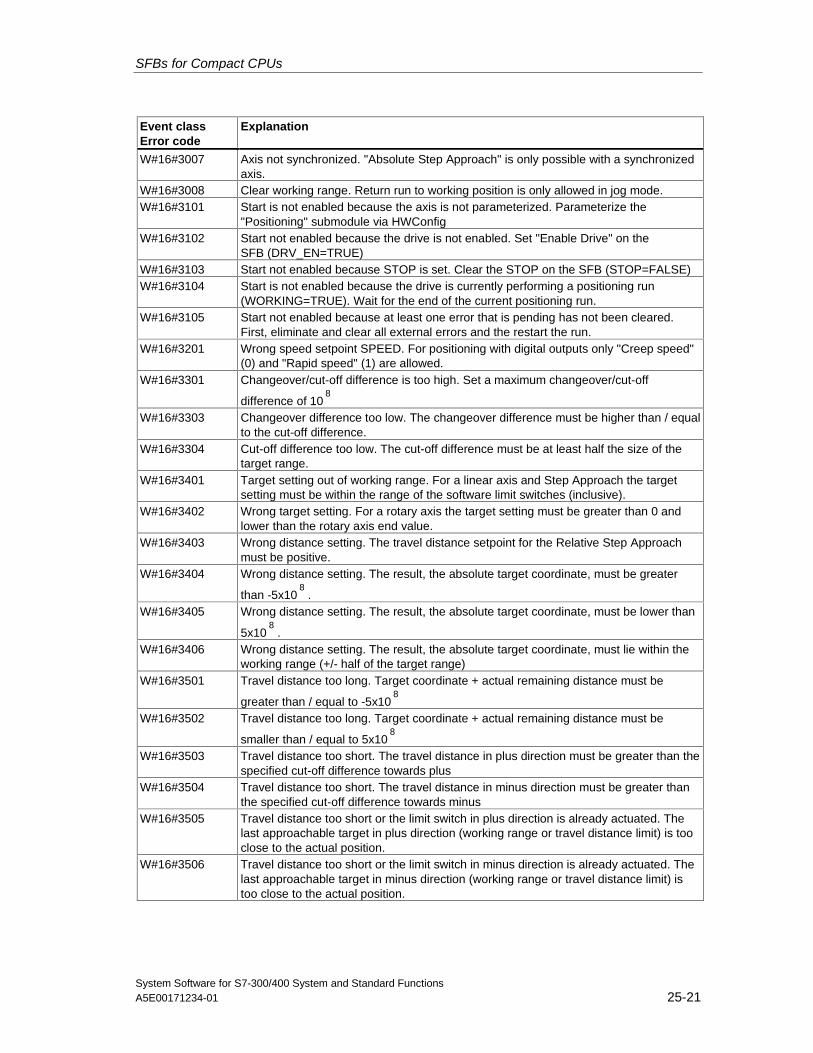
SFBs for Compact CPUs
System Software for S7-300/400 System and Standard FunctionsA5E00171234-01 25-21
Event classError code
Explanation
W#16#3007 Axis not synchronized. "Absolute Step Approach" is only possible with a synchronizedaxis.
W#16#3008 Clear working range. Return run to working position is only allowed in jog mode.W#16#3101 Start is not enabled because the axis is not parameterized. Parameterize the
"Positioning" submodule via HWConfigW#16#3102 Start not enabled because the drive is not enabled. Set "Enable Drive" on the
SFB (DRV_EN=TRUE)W#16#3103 Start not enabled because STOP is set. Clear the STOP on the SFB (STOP=FALSE)W#16#3104 Start is not enabled because the drive is currently performing a positioning run
(WORKING=TRUE). Wait for the end of the current positioning run.W#16#3105 Start not enabled because at least one error that is pending has not been cleared.
First, eliminate and clear all external errors and the restart the run.W#16#3201 Wrong speed setpoint SPEED. For positioning with digital outputs only "Creep speed"
(0) and "Rapid speed" (1) are allowed.W#16#3301 Changeover/cut-off difference is too high. Set a maximum changeover/cut-off
difference of 108
W#16#3303 Changeover difference too low. The changeover difference must be higher than / equalto the cut-off difference.
W#16#3304 Cut-off difference too low. The cut-off difference must be at least half the size of thetarget range.
W#16#3401 Target setting out of working range. For a linear axis and Step Approach the targetsetting must be within the range of the software limit switches (inclusive).
W#16#3402 Wrong target setting. For a rotary axis the target setting must be greater than 0 andlower than the rotary axis end value.
W#16#3403 Wrong distance setting. The travel distance setpoint for the Relative Step Approachmust be positive.
W#16#3404 Wrong distance setting. The result, the absolute target coordinate, must be greater
than -5x10⁸
.W#16#3405 Wrong distance setting. The result, the absolute target coordinate, must be lower than
5x10⁸
.W#16#3406 Wrong distance setting. The result, the absolute target coordinate, must lie within the
working range (+/- half of the target range)W#16#3501 Travel distance too long. Target coordinate + actual remaining distance must be
greater than / equal to -5x10⁸
W#16#3502 Travel distance too long. Target coordinate + actual remaining distance must be
smaller than / equal to 5x10⁸
W#16#3503 Travel distance too short. The travel distance in plus direction must be greater than thespecified cut-off difference towards plus
W#16#3504 Travel distance too short. The travel distance in minus direction must be greater thanthe specified cut-off difference towards minus
W#16#3505 Travel distance too short or the limit switch in plus direction is already actuated. Thelast approachable target in plus direction (working range or travel distance limit) is tooclose to the actual position.
W#16#3506 Travel distance too short or the limit switch in minus direction is already actuated. Thelast approachable target in minus direction (working range or travel distance limit) istoo close to the actual position.

SFBs for Compact CPUs
System Software for S7-300/400 System and Standard Functions25-22 A5E00171234-01
Job Error (JOB_ERR = TRUE)
The output parameter JOB_ERROR is set TRUE if an error is detected. Theparameter JOB_STAT shows the cause of the error.
Event classError code
Explanation
W#16#4001 Axis not parameterized. Parameterize the "Positioning" submodule via HWConfig
W#16#4002 Job not possible because positioning is in progress. Jobs can only be carried out if nopositioning run is in progress. Wait until WORKING = FALSE, then repeat the job.
W#16#4004 Unknown job. Check the job ID and then repeat the job.
W#16#4101 For a linear axis the reference point coordinate must not be out of range of the workingrange limits.
W#16#4102 For a linear axis the specified reference point coordinate + actual remaining distance
must be greater than / equal to -5x10⁸
.
W#16#4103 For a linear axis the specified reference point coordinate + actual remaining distance
must be smaller than / equal to 5x10⁸
.
W#16#4104 For a linear axis the specified reference point coordinate + actual remaining difference
to the starting point must be greater than / equal to -5x10⁸
.
W#16#4105 For a linear axis the specified reference point coordinate + actual remaining difference
to the starting point of the run must be smaller than / equal to -5x10⁸
.
W#16#4106 For a rotary axis the reference point coordinate must not be lower than 0 and greaterthan / equal to the rotary axis end.
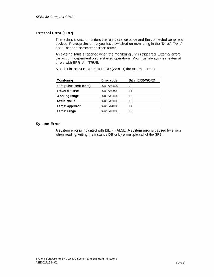
SFBs for Compact CPUs
System Software for S7-300/400 System and Standard FunctionsA5E00171234-01 25-23
External Error (ERR)
The technical circuit monitors the run, travel distance and the connected peripheraldevices. Prerequisite is that you have switched on monitoring in the "Drive", "Axis"and "Encoder" parameter screen forms.
An external fault is reported when the monitoring unit is triggered. External errorscan occur independent on the started operations. You must always clear externalerrors with ERR_A = TRUE.
A set bit in the SFB parameter ERR (WORD) the external errors.
Monitoring Error code Bit in ERR-WORD
Zero pulse (zero mark) W#16#0004 2
Travel distance W#16#0800 11
Working range W#16#1000 12
Actual value W#16#2000 13
Target approach W#16#4000 14
Target range W#16#8000 15
System Error
A system error is indicated with BIE = FALSE. A system error is caused by errorswhen reading/writing the instance DB or by a multiple call of the SFB.
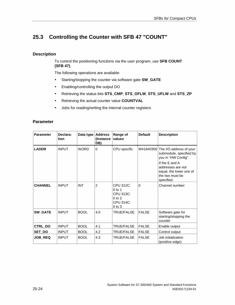
SFBs for Compact CPUs
System Software for S7-300/400 System and Standard Functions25-24 A5E00171234-01
25.3 Controlling the Counter with SFB 47 "COUNT"
Description
To control the positioning functions via the user program, use SFB COUNT(SFB 47).
The following operations are available:
• Starting/stopping the counter via software gate SW_GATE
• Enabling/controlling the output DO
• Retrieving the status bits STS_CMP, STS_OFLW, STS_UFLW and STS_ZP
• Retrieving the actual counter value COUNTVAL
• Jobs for reading/writing the internal counter registers
Parameter
Parameter Declara-tion
Data type Address(InstanceDB)
Range ofvalues
Default Description
LADDR INPUT WORD 0 CPU specific W#16#0300 The I/O address of yoursubmodule, specified byyou in "HW Config".
If the E and Aaddresses are notequal, the lower one ofthe two must bespecified.
CHANNEL INPUT INT 2 CPU 312C:0 to 1CPU 313C:0 to 2CPU 314C:0 to 3
0 Channel number:
SW_GATE INPUT BOOL 4.0 TRUE/FALSE FALSE Software gate forstarting/stopping thecounter
CTRL_DO INPUT BOOL 4.1 TRUE/FALSE FALSE Enable output
SET_DO INPUT BOOL 4.2 TRUE/FALSE FALSE Control output
JOB_REQ INPUT BOOL 4.3 TRUE/FALSE FALSE Job initialization(positive edge)
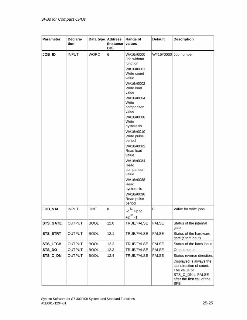
SFBs for Compact CPUs
System Software for S7-300/400 System and Standard FunctionsA5E00171234-01 25-25
Parameter Declara-tion
Data type Address(InstanceDB)
Range ofvalues
Default Description
JOB_ID INPUT WORD 6 W#16#0000Job withoutfunction
W#16#0001Write countvalue
W#16#0002Write loadvalue
W#16#0004Writecomparisonvalue
W#16#0008Writehysteresis
W#16#0010Write pulseperiod
W#16#0082Read loadvalue
W#16#0084Readcomparisonvalue
W#16#0088Readhysteresis
W#16#0090Read pulseperiod
W#16#0000 Job number
JOB_VAL INPUT DINT 8 -231
up to
+231
-1
0 Value for write jobs.
STS_GATE OUTPUT BOOL 12.0 TRUE/FALSE FALSE Status of the internalgate
STS_STRT OUTPUT BOOL 12.1 TRUE/FALSE FALSE Status of the hardwaregate (Start input)
STS_LTCH OUTPUT BOOL 12.2 TRUE/FALSE FALSE Status of the latch input
STS_DO OUTPUT BOOL 12.3 TRUE/FALSE FALSE Output status
STS_C_DN OUTPUT BOOL 12.4 TRUE/FALSE FALSE Status reverse direction.
Displayed is always thelast direction of count.The value ofSTS_C_DN is FALSEafter the first call of theSFB.
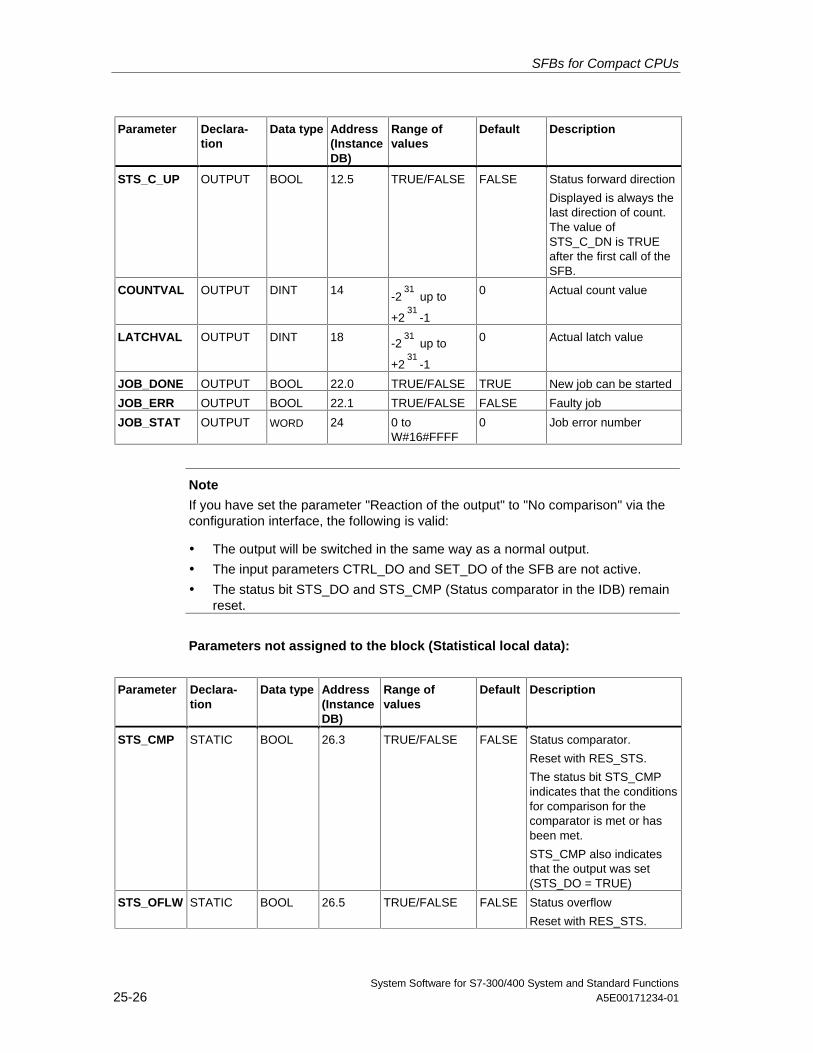
SFBs for Compact CPUs
System Software for S7-300/400 System and Standard Functions25-26 A5E00171234-01
Parameter Declara-tion
Data type Address(InstanceDB)
Range ofvalues
Default Description
STS_C_UP OUTPUT BOOL 12.5 TRUE/FALSE FALSE Status forward direction
Displayed is always thelast direction of count.The value ofSTS_C_DN is TRUEafter the first call of theSFB.
COUNTVAL OUTPUT DINT 14 -231
up to
+231
-1
0 Actual count value
LATCHVAL OUTPUT DINT 18 -231
up to
+231
-1
0 Actual latch value
JOB_DONE OUTPUT BOOL 22.0 TRUE/FALSE TRUE New job can be started
JOB_ERR OUTPUT BOOL 22.1 TRUE/FALSE FALSE Faulty job
JOB_STAT OUTPUT WORD 24 0 toW#16#FFFF
0 Job error number
Note
If you have set the parameter "Reaction of the output" to "No comparison" via theconfiguration interface, the following is valid:
• The output will be switched in the same way as a normal output.
• The input parameters CTRL_DO and SET_DO of the SFB are not active.
• The status bit STS_DO and STS_CMP (Status comparator in the IDB) remainreset.
Parameters not assigned to the block (Statistical local data):
Parameter Declara-tion
Data type Address(InstanceDB)
Range ofvalues
Default Description
STS_CMP STATIC BOOL 26.3 TRUE/FALSE FALSE Status comparator.
Reset with RES_STS.
The status bit STS_CMPindicates that the conditionsfor comparison for thecomparator is met or hasbeen met.
STS_CMP also indicatesthat the output was set(STS_DO = TRUE)
STS_OFLW STATIC BOOL 26.5 TRUE/FALSE FALSE Status overflow
Reset with RES_STS.
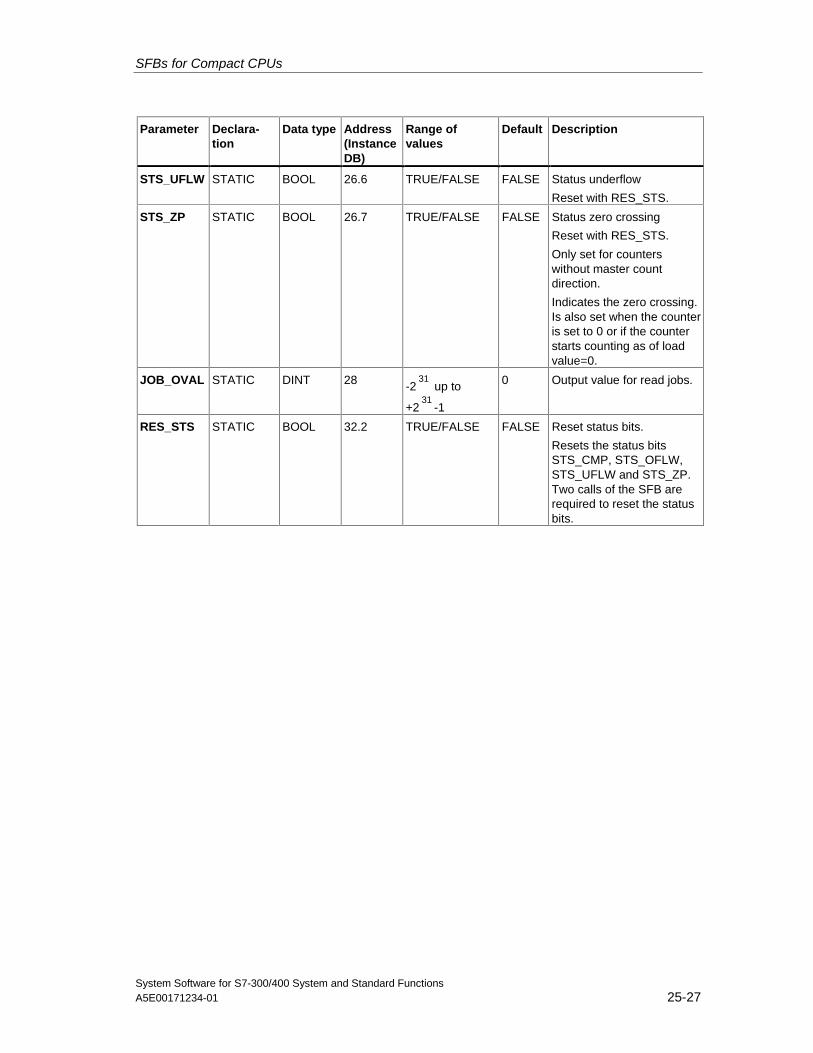
SFBs for Compact CPUs
System Software for S7-300/400 System and Standard FunctionsA5E00171234-01 25-27
Parameter Declara-tion
Data type Address(InstanceDB)
Range ofvalues
Default Description
STS_UFLW STATIC BOOL 26.6 TRUE/FALSE FALSE Status underflow
Reset with RES_STS.
STS_ZP STATIC BOOL 26.7 TRUE/FALSE FALSE Status zero crossing
Reset with RES_STS.
Only set for counterswithout master countdirection.
Indicates the zero crossing.Is also set when the counteris set to 0 or if the counterstarts counting as of loadvalue=0.
JOB_OVAL STATIC DINT 28 -231
up to
+231
-1
0 Output value for read jobs.
RES_STS STATIC BOOL 32.2 TRUE/FALSE FALSE Reset status bits.
Resets the status bitsSTS_CMP, STS_OFLW,STS_UFLW and STS_ZP.Two calls of the SFB arerequired to reset the statusbits.
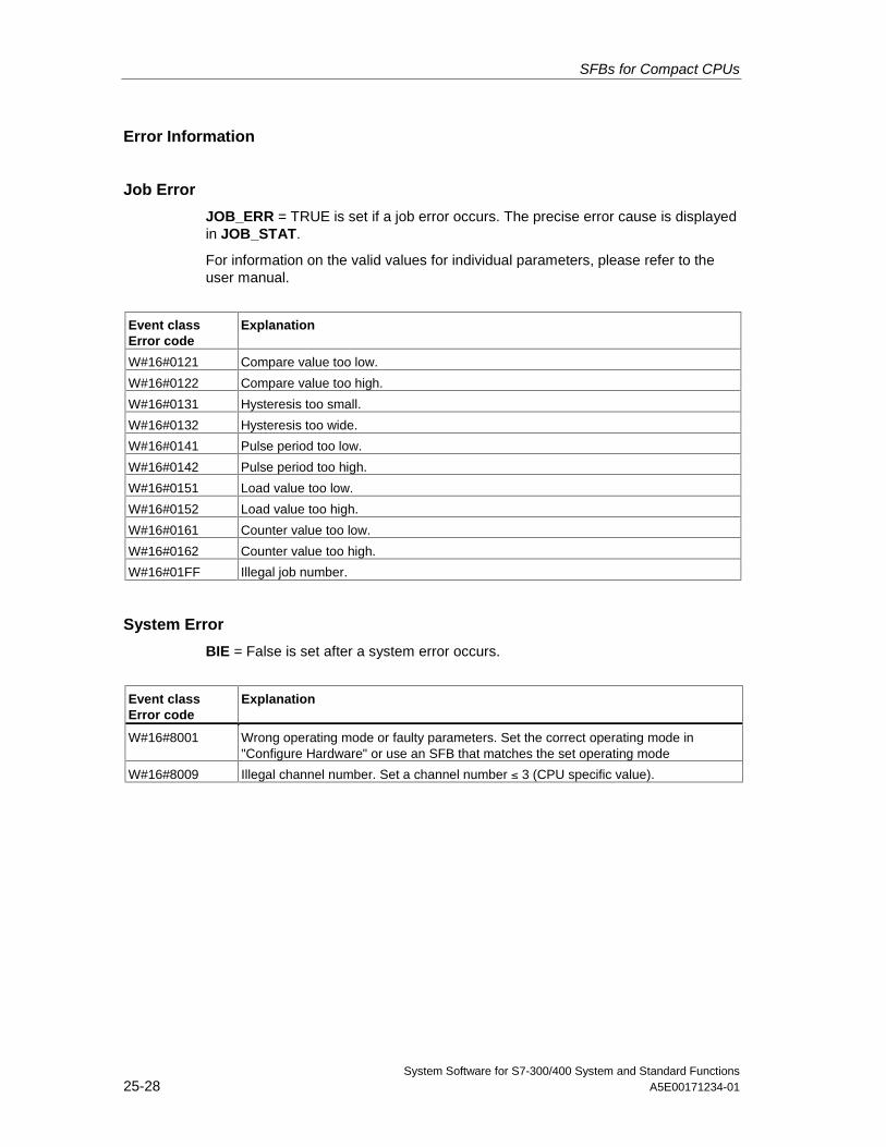
SFBs for Compact CPUs
System Software for S7-300/400 System and Standard Functions25-28 A5E00171234-01
Error Information
Job Error
JOB_ERR = TRUE is set if a job error occurs. The precise error cause is displayedin JOB_STAT.
For information on the valid values for individual parameters, please refer to theuser manual.
Event classError code
Explanation
W#16#0121 Compare value too low.
W#16#0122 Compare value too high.
W#16#0131 Hysteresis too small.
W#16#0132 Hysteresis too wide.
W#16#0141 Pulse period too low.
W#16#0142 Pulse period too high.
W#16#0151 Load value too low.
W#16#0152 Load value too high.
W#16#0161 Counter value too low.
W#16#0162 Counter value too high.
W#16#01FF Illegal job number.
System Error
BIE = False is set after a system error occurs.
Event classError code
Explanation
W#16#8001 Wrong operating mode or faulty parameters. Set the correct operating mode in"Configure Hardware" or use an SFB that matches the set operating mode
W#16#8009 Illegal channel number. Set a channel number ≤ 3 (CPU specific value).
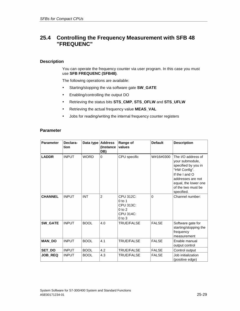
SFBs for Compact CPUs
System Software for S7-300/400 System and Standard FunctionsA5E00171234-01 25-29
25.4 Controlling the Frequency Measurement with SFB 48"FREQUENC"
Description
You can operate the frequency counter via user program. In this case you mustuse SFB FREQUENC (SFB48).
The following operations are available:
• Starting/stopping the via software gate SW_GATE
• Enabling/controlling the output DO
• Retrieving the status bits STS_CMP, STS_OFLW and STS_UFLW
• Retrieving the actual frequency value MEAS_VAL
• Jobs for reading/writing the internal frequency counter registers
Parameter
Parameter Declara-tion
Data type Address(InstanceDB)
Range ofvalues
Default Description
LADDR INPUT WORD 0 CPU specific W#16#0300 The I/O address ofyour submodule,specified by you in"HW Config".If the I and Oaddresses are notequal, the lower oneof the two must bespecified.
CHANNEL INPUT INT 2 CPU 312C:0 to 1CPU 313C:0 to 2CPU 314C:0 to 3
0 Channel number:
SW_GATE INPUT BOOL 4.0 TRUE/FALSE FALSE Software gate forstarting/stopping thefrequencymeasurement
MAN_DO INPUT BOOL 4.1 TRUE/FALSE FALSE Enable manualoutput control
SET_DO INPUT BOOL 4.2 TRUE/FALSE FALSE Control outputJOB_REQ INPUT BOOL 4.3 TRUE/FALSE FALSE Job initialization
(positive edge)
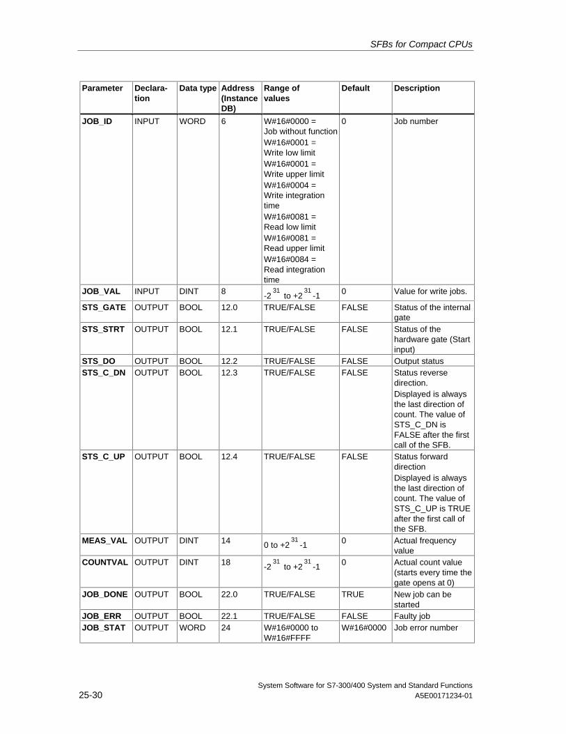
SFBs for Compact CPUs
System Software for S7-300/400 System and Standard Functions25-30 A5E00171234-01
Parameter Declara-tion
Data type Address(InstanceDB)
Range ofvalues
Default Description
JOB_ID INPUT WORD 6 W#16#0000 =Job without functionW#16#0001 =Write low limitW#16#0001 =Write upper limitW#16#0004 =Write integrationtimeW#16#0081 =Read low limitW#16#0081 =Read upper limitW#16#0084 =Read integrationtime
0 Job number
JOB_VAL INPUT DINT 8 -231
to +231
-1 0 Value for write jobs.
STS_GATE OUTPUT BOOL 12.0 TRUE/FALSE FALSE Status of the internalgate
STS_STRT OUTPUT BOOL 12.1 TRUE/FALSE FALSE Status of thehardware gate (Startinput)
STS_DO OUTPUT BOOL 12.2 TRUE/FALSE FALSE Output statusSTS_C_DN OUTPUT BOOL 12.3 TRUE/FALSE FALSE Status reverse
direction.Displayed is alwaysthe last direction ofcount. The value ofSTS_C_DN isFALSE after the firstcall of the SFB.
STS_C_UP OUTPUT BOOL 12.4 TRUE/FALSE FALSE Status forwarddirectionDisplayed is alwaysthe last direction ofcount. The value ofSTS_C_UP is TRUEafter the first call ofthe SFB.
MEAS_VAL OUTPUT DINT 14 0 to +231
-1 0 Actual frequencyvalue
COUNTVAL OUTPUT DINT 18 -231
to +231
-1 0 Actual count value(starts every time thegate opens at 0)
JOB_DONE OUTPUT BOOL 22.0 TRUE/FALSE TRUE New job can bestarted
JOB_ERR OUTPUT BOOL 22.1 TRUE/FALSE FALSE Faulty jobJOB_STAT OUTPUT WORD 24 W#16#0000 to
W#16#FFFFW#16#0000 Job error number
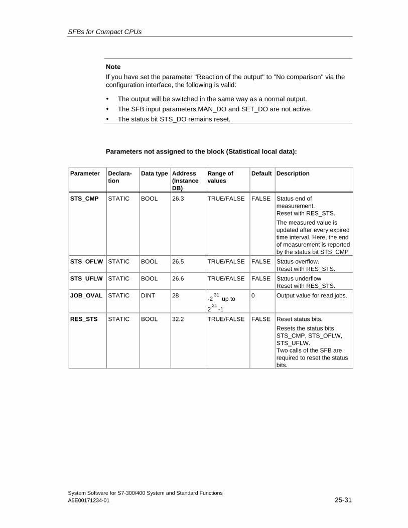
SFBs for Compact CPUs
System Software for S7-300/400 System and Standard FunctionsA5E00171234-01 25-31
Note
If you have set the parameter "Reaction of the output" to "No comparison" via theconfiguration interface, the following is valid:
• The output will be switched in the same way as a normal output.
• The SFB input parameters MAN_DO and SET_DO are not active.
• The status bit STS_DO remains reset.
Parameters not assigned to the block (Statistical local data):
Parameter Declara-tion
Data type Address(InstanceDB)
Range ofvalues
Default Description
STS_CMP STATIC BOOL 26.3 TRUE/FALSE FALSE Status end ofmeasurement.Reset with RES_STS.
The measured value isupdated after every expiredtime interval. Here, the endof measurement is reportedby the status bit STS_CMP
STS_OFLW STATIC BOOL 26.5 TRUE/FALSE FALSE Status overflow.Reset with RES_STS.
STS_UFLW STATIC BOOL 26.6 TRUE/FALSE FALSE Status underflowReset with RES_STS.
JOB_OVAL STATIC DINT 28 -231
up to
231
-1
0 Output value for read jobs.
RES_STS STATIC BOOL 32.2 TRUE/FALSE FALSE Reset status bits.
Resets the status bitsSTS_CMP, STS_OFLW,STS_UFLW.Two calls of the SFB arerequired to reset the statusbits.
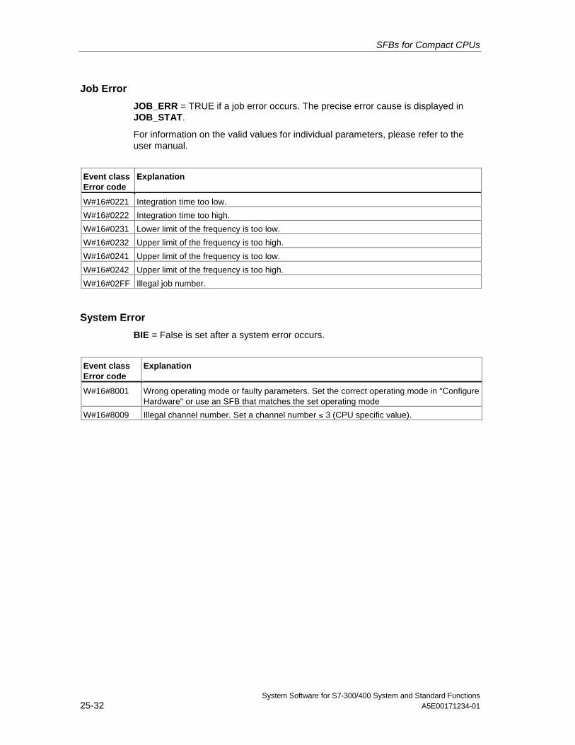
SFBs for Compact CPUs
System Software for S7-300/400 System and Standard Functions25-32 A5E00171234-01
Job Error
JOB_ERR = TRUE if a job error occurs. The precise error cause is displayed inJOB_STAT.
For information on the valid values for individual parameters, please refer to theuser manual.
Event classError code
Explanation
W#16#0221 Integration time too low.
W#16#0222 Integration time too high.
W#16#0231 Lower limit of the frequency is too low.
W#16#0232 Upper limit of the frequency is too high.
W#16#0241 Upper limit of the frequency is too low.
W#16#0242 Upper limit of the frequency is too high.
W#16#02FF Illegal job number.
System Error
BIE = False is set after a system error occurs.
Event classError code
Explanation
W#16#8001 Wrong operating mode or faulty parameters. Set the correct operating mode in "ConfigureHardware" or use an SFB that matches the set operating mode
W#16#8009 Illegal channel number. Set a channel number ≤ 3 (CPU specific value).
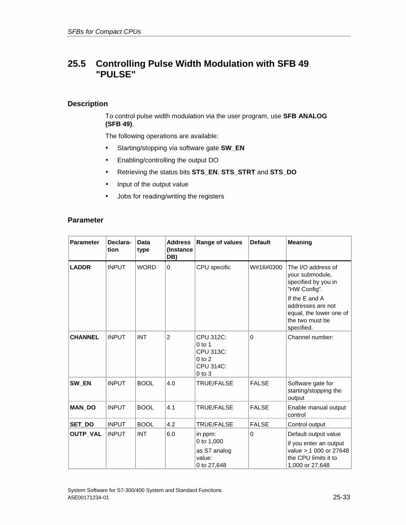
SFBs for Compact CPUs
System Software for S7-300/400 System and Standard FunctionsA5E00171234-01 25-33
25.5 Controlling Pulse Width Modulation with SFB 49"PULSE"
Description
To control pulse width modulation via the user program, use SFB ANALOG(SFB 49).
The following operations are available:
• Starting/stopping via software gate SW_EN
• Enabling/controlling the output DO
• Retrieving the status bits STS_EN, STS_STRT and STS_DO
• Input of the output value
• Jobs for reading/writing the registers
Parameter
Parameter Declara-tion
Datatype
Address(InstanceDB)
Range of values Default Meaning
LADDR INPUT WORD 0 CPU specific W#16#0300 The I/O address ofyour submodule,specified by you in"HW Config".
If the E and Aaddresses are notequal, the lower one ofthe two must bespecified.
CHANNEL INPUT INT 2 CPU 312C:0 to 1CPU 313C:0 to 2CPU 314C:0 to 3
0 Channel number:
SW_EN INPUT BOOL 4.0 TRUE/FALSE FALSE Software gate forstarting/stopping theoutput
MAN_DO INPUT BOOL 4.1 TRUE/FALSE FALSE Enable manual outputcontrol
SET_DO INPUT BOOL 4.2 TRUE/FALSE FALSE Control output
OUTP_VAL INPUT INT 6.0 in ppm:0 to 1,000
as S7 analogvalue:0 to 27,648
0 Default output value
if you enter an outputvalue > 1 000 or 27648the CPU limits it to1,000 or 27,648
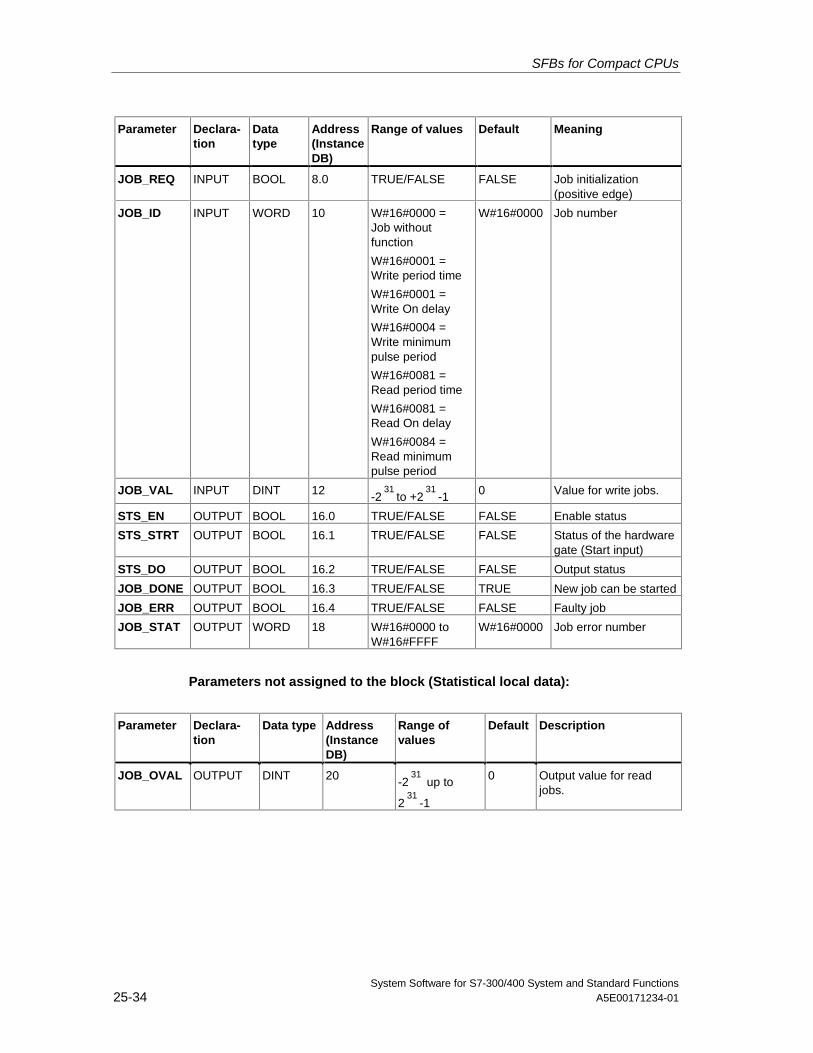
SFBs for Compact CPUs
System Software for S7-300/400 System and Standard Functions25-34 A5E00171234-01
Parameter Declara-tion
Datatype
Address(InstanceDB)
Range of values Default Meaning
JOB_REQ INPUT BOOL 8.0 TRUE/FALSE FALSE Job initialization(positive edge)
JOB_ID INPUT WORD 10 W#16#0000 =Job withoutfunction
W#16#0001 =Write period time
W#16#0001 =Write On delay
W#16#0004 =Write minimumpulse period
W#16#0081 =Read period time
W#16#0081 =Read On delay
W#16#0084 =Read minimumpulse period
W#16#0000 Job number
JOB_VAL INPUT DINT 12 -231
to +231
-1 0 Value for write jobs.
STS_EN OUTPUT BOOL 16.0 TRUE/FALSE FALSE Enable status
STS_STRT OUTPUT BOOL 16.1 TRUE/FALSE FALSE Status of the hardwaregate (Start input)
STS_DO OUTPUT BOOL 16.2 TRUE/FALSE FALSE Output status
JOB_DONE OUTPUT BOOL 16.3 TRUE/FALSE TRUE New job can be started
JOB_ERR OUTPUT BOOL 16.4 TRUE/FALSE FALSE Faulty job
JOB_STAT OUTPUT WORD 18 W#16#0000 toW#16#FFFF
W#16#0000 Job error number
Parameters not assigned to the block (Statistical local data):
Parameter Declara-tion
Data type Address(InstanceDB)
Range ofvalues
Default Description
JOB_OVAL OUTPUT DINT 20 -231
up to
231
-1
0 Output value for readjobs.
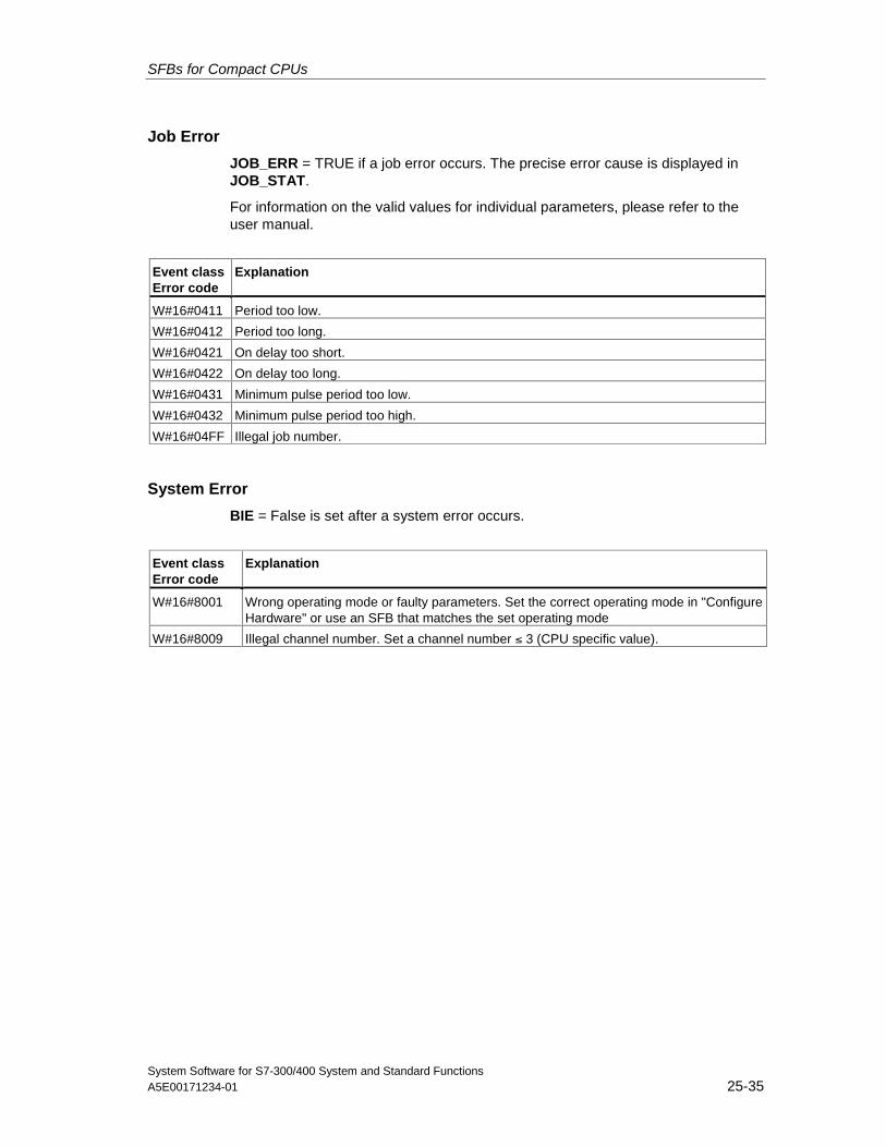
SFBs for Compact CPUs
System Software for S7-300/400 System and Standard FunctionsA5E00171234-01 25-35
Job Error
JOB_ERR = TRUE if a job error occurs. The precise error cause is displayed inJOB_STAT.
For information on the valid values for individual parameters, please refer to theuser manual.
Event classError code
Explanation
W#16#0411 Period too low.
W#16#0412 Period too long.
W#16#0421 On delay too short.
W#16#0422 On delay too long.
W#16#0431 Minimum pulse period too low.
W#16#0432 Minimum pulse period too high.
W#16#04FF Illegal job number.
System Error
BIE = False is set after a system error occurs.
Event classError code
Explanation
W#16#8001 Wrong operating mode or faulty parameters. Set the correct operating mode in "ConfigureHardware" or use an SFB that matches the set operating mode
W#16#8009 Illegal channel number. Set a channel number ≤ 3 (CPU specific value).
SFBs for Compact CPUs
System Software for S7-300/400 System and Standard Functions25-36 A5E00171234-01
25.6 Sending Data (ASCII, 3964(R)) with SFB 60 "SEND_PTP"
Description
You can transmit a data block from a DB via SFB SEND_PTP (SFB 60).
The send operation is executed after the block is called and a positive edge oncontrol input REQ.
The range of data to be transmitted is determined in SD_1 (DB number and startaddress). The length of the data block is determined in LEN.
To enable the SFB to process the job, you must call it with R(Reset)=FALSE. Atthe positive edge on control input R the current transmission is aborted and theSFB is reset to basic state. An aborted job is terminated with an error message(STATUS output).
For your submodule, you declare the I/O address, which you specified in"HW Config", in LADDR.
DONE is set TRUE if the job was terminated without error, or ERROR is set TRUEif the job was terminated with an error.
If the job was processed with DONE=TRUE this means that:
• When using the ASCII driver: The data where transmitted to thecommunication partner. It is not ensured that all data has been received by thecommunication partner.
• When using the procedure 3964(R): The data have been transmitted to thecommunication partner and they where acknowledged positively by thepartner. It is not ensured that the data were passed on the partner CPU.
In STATUS the CPU indicates an error or, as a result of a warning, the respectiveevent ID.
DONE or ERROR/STATUS are also output when the SFB is RESET (R=TRUE).
The binary result BIE is reset if an error has occurred. The status of the binaryresult is TRUE if the block was terminated without error.
Note
A parameter check is not included in the SFB. The CPU might go into STOP modeif the parameterization is faulty.
Instance DB
The SFB SEND_PTP operates in combination with an instance DB. The DBnumber is passed on with the call. Accessing data in the instance DB is notpermitted.
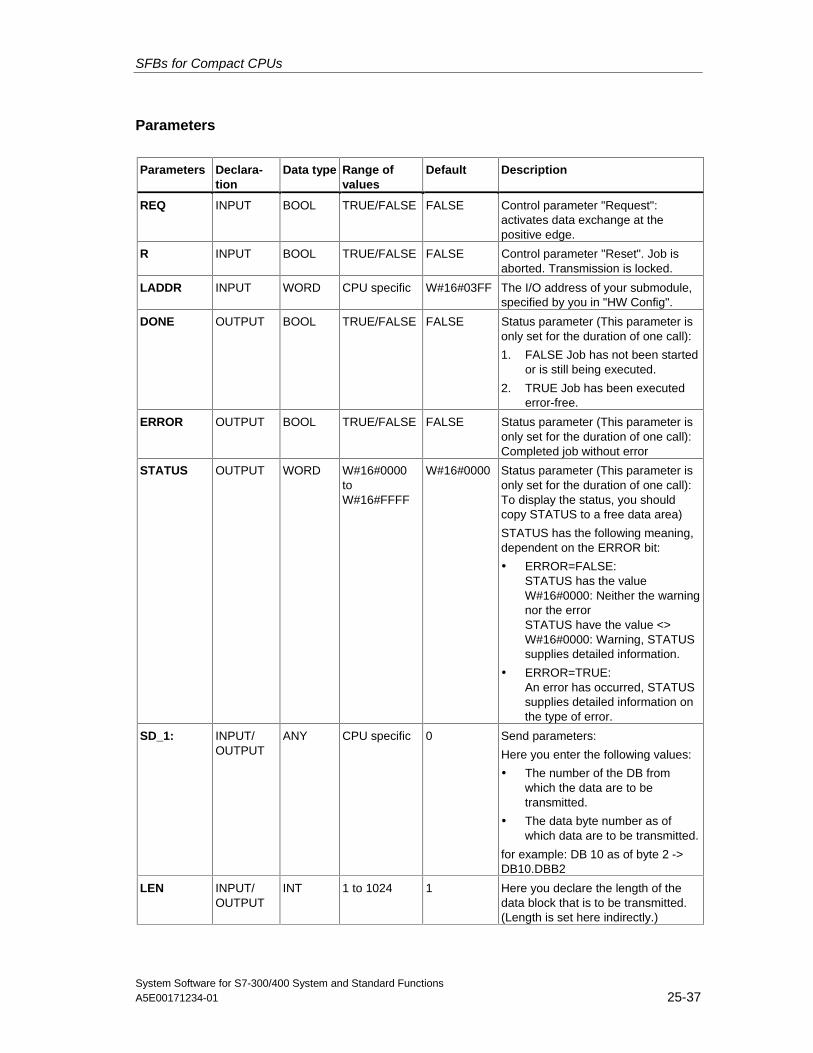
SFBs for Compact CPUs
System Software for S7-300/400 System and Standard FunctionsA5E00171234-01 25-37
Parameters
Parameters Declara-tion
Data type Range ofvalues
Default Description
REQ INPUT BOOL TRUE/FALSE FALSE Control parameter "Request":activates data exchange at thepositive edge.
R INPUT BOOL TRUE/FALSE FALSE Control parameter "Reset". Job isaborted. Transmission is locked.
LADDR INPUT WORD CPU specific W#16#03FF The I/O address of your submodule,specified by you in "HW Config".
DONE OUTPUT BOOL TRUE/FALSE FALSE Status parameter (This parameter isonly set for the duration of one call):
1. FALSE Job has not been startedor is still being executed.
2. TRUE Job has been executederror-free.
ERROR OUTPUT BOOL TRUE/FALSE FALSE Status parameter (This parameter isonly set for the duration of one call):Completed job without error
STATUS OUTPUT WORD W#16#0000toW#16#FFFF
W#16#0000 Status parameter (This parameter isonly set for the duration of one call):To display the status, you shouldcopy STATUS to a free data area)
STATUS has the following meaning,dependent on the ERROR bit:
• ERROR=FALSE:STATUS has the valueW#16#0000: Neither the warningnor the errorSTATUS have the value <>W#16#0000: Warning, STATUSsupplies detailed information.
• ERROR=TRUE:An error has occurred, STATUSsupplies detailed information onthe type of error.
SD_1: INPUT/OUTPUT
ANY CPU specific 0 Send parameters:
Here you enter the following values:
• The number of the DB fromwhich the data are to betransmitted.
• The data byte number as ofwhich data are to be transmitted.
for example: DB 10 as of byte 2 ->DB10.DBB2
LEN INPUT/OUTPUT
INT 1 to 1024 1 Here you declare the length of thedata block that is to be transmitted.(Length is set here indirectly.)
SFBs for Compact CPUs
System Software for S7-300/400 System and Standard Functions25-38 A5E00171234-01
Data Consistency
Data consistency is limited to 206 bytes. If you want to consistent datatransmission exceeding these 206 bytes, you must take the following into account:
Do not write to the currently used section of the send range SD_1 unless thetransmission has been terminated. This is the case when the state parameterDONE has the value TRUE.
SFBs for Compact CPUs
System Software for S7-300/400 System and Standard FunctionsA5E00171234-01 25-39
25.7 Receiving Data (ASCII, 3964(R)) with SFB 61 "RCV_PTP"
Description
With the SFB RCV_PTP (SFB 61) you receive data and then file them in a datablock.
The block is ready to receive data after it is called and when the control inputEN_R is TRUE. You can cancel the current transmission by setting the signalstatus of parameter EN_R to FALSE. A cancelled job is terminated with an errormessage (STATUS output). The input is switched off as long as the signal status ofparameter EN_R is set to FALSE.
The receiving area declared in RD_1 (DB number and start address). The length ofthe data block is declared in LEN.
To enable the SFB to process the job, you must call it with R(Reset)=FALSE. Atthe positive edge on control input R the current transmission is aborted and theSFB is reset to basic state. A cancelled job is terminated with an error message(STATUS output).
For your submodule, you declare the I/O address, which you specified by in "HWConfig", in LADDR.
NDR is set TRUE if the job was terminated without error, or ERROR is set TRUE ifthe job was terminated with an error.
In STATUS, the CPU indicates an error or, as a result of a warning, the respectiveevent ID.
NDR or ERROR/STATUS are also output (parameter LEN = 16#00) when the SFBis RESET (R=TRUE).
The binary result BIE is reset if an error has occurred. The status of the binaryresult is TRUE if the block was terminated without error.
Note
A parameter check is not included in the SFB. The CPU might jump to STOP modeif the configuration is faulty.
Instance DB
The SFB RCV_PTP operates in combination with an instance DB. The DB numberis passed on with the call. Access to the data in the instance DB is not allowed.
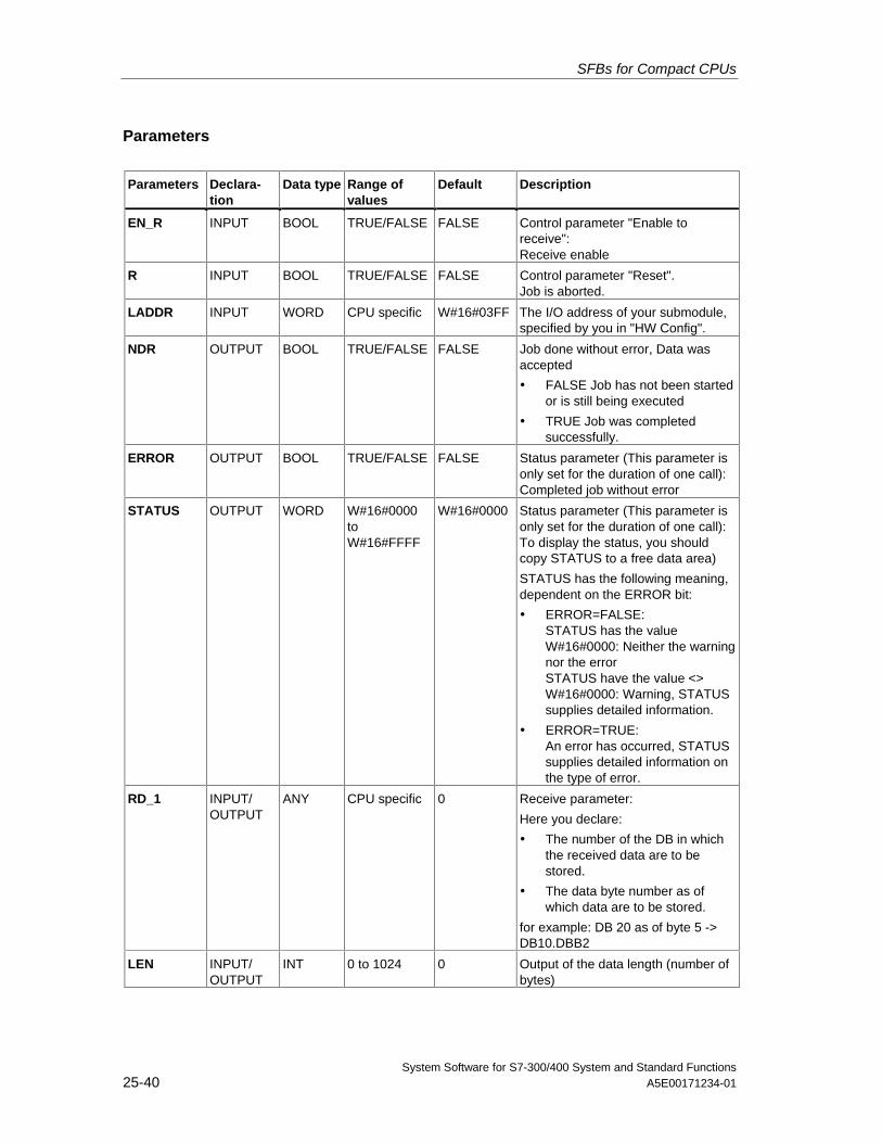
SFBs for Compact CPUs
System Software for S7-300/400 System and Standard Functions25-40 A5E00171234-01
Parameters
Parameters Declara-tion
Data type Range ofvalues
Default Description
EN_R INPUT BOOL TRUE/FALSE FALSE Control parameter "Enable toreceive":Receive enable
R INPUT BOOL TRUE/FALSE FALSE Control parameter "Reset".Job is aborted.
LADDR INPUT WORD CPU specific W#16#03FF The I/O address of your submodule,specified by you in "HW Config".
NDR OUTPUT BOOL TRUE/FALSE FALSE Job done without error, Data wasaccepted
• FALSE Job has not been startedor is still being executed
• TRUE Job was completedsuccessfully.
ERROR OUTPUT BOOL TRUE/FALSE FALSE Status parameter (This parameter isonly set for the duration of one call):Completed job without error
STATUS OUTPUT WORD W#16#0000toW#16#FFFF
W#16#0000 Status parameter (This parameter isonly set for the duration of one call):To display the status, you shouldcopy STATUS to a free data area)
STATUS has the following meaning,dependent on the ERROR bit:
• ERROR=FALSE:STATUS has the valueW#16#0000: Neither the warningnor the errorSTATUS have the value <>W#16#0000: Warning, STATUSsupplies detailed information.
• ERROR=TRUE:An error has occurred, STATUSsupplies detailed information onthe type of error.
RD_1 INPUT/OUTPUT
ANY CPU specific 0 Receive parameter:
Here you declare:
• The number of the DB in whichthe received data are to bestored.
• The data byte number as ofwhich data are to be stored.
for example: DB 20 as of byte 5 ->DB10.DBB2
LEN INPUT/OUTPUT
INT 0 to 1024 0 Output of the data length (number ofbytes)
SFBs for Compact CPUs
System Software for S7-300/400 System and Standard FunctionsA5E00171234-01 25-41
Data Consistency
Data consistency is limited to 206 bytes. If you want consistent data transmissionto exceed these 206 bytes, you must take the following points into account:
Do not access the receive DB until the data have been completely received (NDR= TRUE). Then, lock the receiving DB (EN_R = FALSE) until you have processedthe data.
SFBs for Compact CPUs
System Software for S7-300/400 System and Standard Functions25-42 A5E00171234-01
25.8 Deleting the Receive Buffer (ASCII, 3964(R)) with SFB 62"RES_RCVB"
Description
You can clear the entire input buffer of the module, using the SFB RES_RECV(SFB 62). All stored telegrams are discarded. An incoming message frame isstored when the SFB RES_RCVB is being called.
The job is activated after the block is called and at the positive edge on controlinput REQ. The job can run across multiple calls (program cycles).
To enable the SFB to process the job, you must call it with R(Reset)=FALSE. Atthe positive edge on control input R the delete process is cancelled and the SFB isreset to basic state. A cancelled job is terminated with an error message (STATUSoutput).
For your submodule, you declare the I/O address, which was specified by you in"HW Config", in LADDR.
DONE is TRUE is the job was terminated without error, or ERROR is TRUE if thejob was terminated with an error.
In STATUS, the CPU indicates an error or, as a result of a warning, the respectiveevent ID.
DONE or ERROR/STATUS are also output when the SFB is RESET (R=TRUE).
The binary result BIE is reset if an error has occurred. The status of the binaryresult is TRUE if the block was terminated without error.
Note
A parameter check is not included in the SFB. The CPU might jump to STOP modeif the parameterization is faulty.
Instance DB
The SFB RES_RCVB operates in combination with an instance DB. The DBnumber is passed on with the call. Access to the data in the instance DB is notallowed.
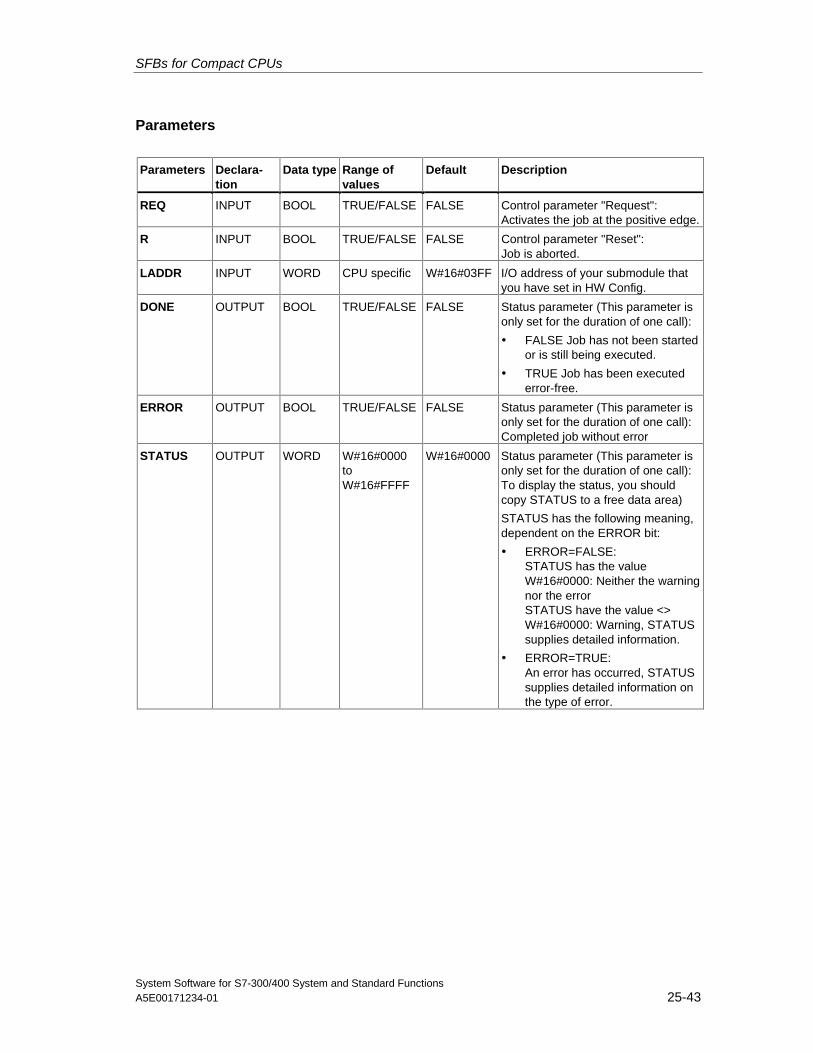
SFBs for Compact CPUs
System Software for S7-300/400 System and Standard FunctionsA5E00171234-01 25-43
Parameters
Parameters Declara-tion
Data type Range ofvalues
Default Description
REQ INPUT BOOL TRUE/FALSE FALSE Control parameter "Request":Activates the job at the positive edge.
R INPUT BOOL TRUE/FALSE FALSE Control parameter "Reset":Job is aborted.
LADDR INPUT WORD CPU specific W#16#03FF I/O address of your submodule thatyou have set in HW Config.
DONE OUTPUT BOOL TRUE/FALSE FALSE Status parameter (This parameter isonly set for the duration of one call):
• FALSE Job has not been startedor is still being executed.
• TRUE Job has been executederror-free.
ERROR OUTPUT BOOL TRUE/FALSE FALSE Status parameter (This parameter isonly set for the duration of one call):Completed job without error
STATUS OUTPUT WORD W#16#0000toW#16#FFFF
W#16#0000 Status parameter (This parameter isonly set for the duration of one call):To display the status, you shouldcopy STATUS to a free data area)
STATUS has the following meaning,dependent on the ERROR bit:
• ERROR=FALSE:STATUS has the valueW#16#0000: Neither the warningnor the errorSTATUS have the value <>W#16#0000: Warning, STATUSsupplies detailed information.
• ERROR=TRUE:An error has occurred, STATUSsupplies detailed information onthe type of error.
SFBs for Compact CPUs
System Software for S7-300/400 System and Standard Functions25-44 A5E00171234-01
25.9 Sending Data (512(R)) with SFB 63 "SEND_RK"
Description
You can send a data from a data block via SFB SEND_PTP (SFB 63).
The send operation is executed after the block is called and a positive edge oncontrol input REQ.
The range of data to be transmitted is determined in SD_1 (DB number and startaddress). The length of the data block is determined in LEN.
In the SFB you also declare the receive range of the partner station. The CPUenters this information in the message frame header (refer also to appendix F) andtransfers it to the partner.
The target is specified by the CPU number R_CPU (only relevant formultiprocessor communication), the data type in R_TYPE (data blocks (DB) andexpanded data blocks (DX)), the data block number in R_DBNO and the offset inR_OFFSET to where the first byte is to be written.
In R_CF_BYT and R_CF_BIT, declare the connection memory byte and bit on thepartner CPU.
In parameter SYNC_DB, declare the DB in which the data that you used in allSFBs for the initialization during startup and synchronization is to be stored. TheDB numbers must be identical for all SFBs in your user program.
To enable the SFB to process the job, you must call it with R(Reset)=FALSE. Atthe positive edge on control input R the current send operation is cancelled and theSFB is reset to basic state. A cancelled job is terminated with an error message(STATUS output).
For your submodule, you declare the I/O address, which you specified in "HWConfig", in LADDR.
DONE is set TRUE if the job was terminated without error, or ERROR is set TRUEif the job was terminated with an error.
Once the job was processed with DONE = TRUE, the data are sent to thecommunication partner that confirms them positively and passes them on to thepartner CPU.
In STATUS, the CPU indicates an error or, as a result of a warning, the respectiveevent ID.
DONE or ERROR/STATUS are also output when the SFB is RESET (R=TRUE).
The binary result BIE is reset if an error has occurred. The status of the binaryresult is TRUE if the block was terminated without error.
Note
A parameter check is not included in the SFB. If the CPU is assigned the wrongparameters it might jump to STOP mode.
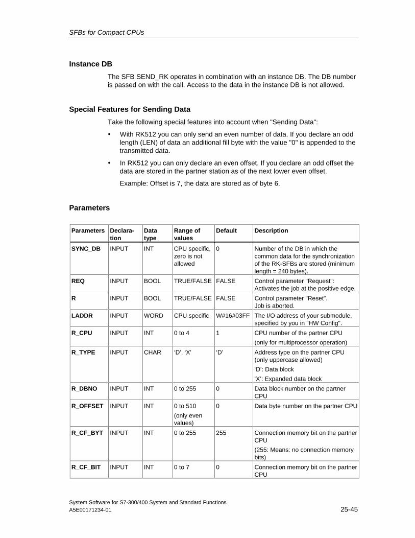
SFBs for Compact CPUs
System Software for S7-300/400 System and Standard FunctionsA5E00171234-01 25-45
Instance DB
The SFB SEND_RK operates in combination with an instance DB. The DB numberis passed on with the call. Access to the data in the instance DB is not allowed.
Special Features for Sending Data
Take the following special features into account when "Sending Data":
• With RK512 you can only send an even number of data. If you declare an oddlength (LEN) of data an additional fill byte with the value "0" is appended to thetransmitted data.
• In RK512 you can only declare an even offset. If you declare an odd offset thedata are stored in the partner station as of the next lower even offset.
Example: Offset is 7, the data are stored as of byte 6.
Parameters
Parameters Declara-tion
Datatype
Range ofvalues
Default Description
SYNC_DB INPUT INT CPU specific,zero is notallowed
0 Number of the DB in which thecommon data for the synchronizationof the RK-SFBs are stored (minimumlength = 240 bytes).
REQ INPUT BOOL TRUE/FALSE FALSE Control parameter "Request":Activates the job at the positive edge.
R INPUT BOOL TRUE/FALSE FALSE Control parameter "Reset".Job is aborted.
LADDR INPUT WORD CPU specific W#16#03FF The I/O address of your submodule,specified by you in "HW Config".
R_CPU INPUT INT 0 to 4 1 CPU number of the partner CPU
(only for multiprocessor operation)
R_TYPE INPUT CHAR ‘D’, ‘X’ ‘D’ Address type on the partner CPU(only uppercase allowed)
‘D’: Data block
‘X’: Expanded data block
R_DBNO INPUT INT 0 to 255 0 Data block number on the partnerCPU
R_OFFSET INPUT INT 0 to 510
(only evenvalues)
0 Data byte number on the partner CPU
R_CF_BYT INPUT INT 0 to 255 255 Connection memory bit on the partnerCPU
(255: Means: no connection memorybits)
R_CF_BIT INPUT INT 0 to 7 0 Connection memory bit on the partnerCPU
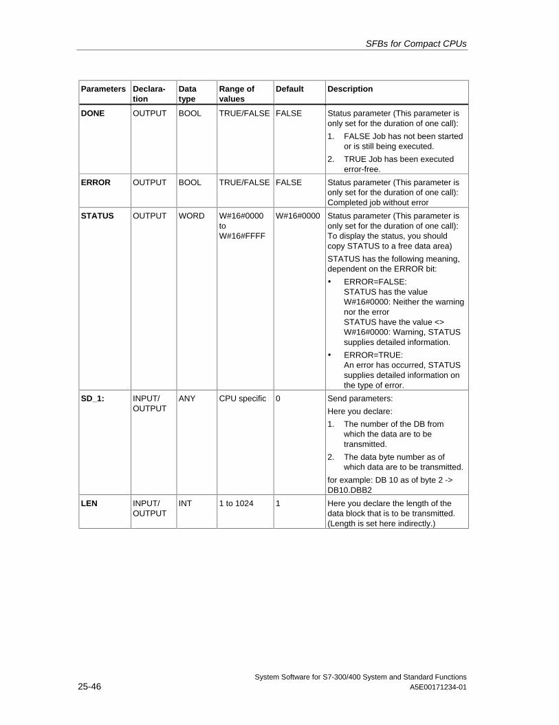
SFBs for Compact CPUs
System Software for S7-300/400 System and Standard Functions25-46 A5E00171234-01
Parameters Declara-tion
Datatype
Range ofvalues
Default Description
DONE OUTPUT BOOL TRUE/FALSE FALSE Status parameter (This parameter isonly set for the duration of one call):
1. FALSE Job has not been startedor is still being executed.
2. TRUE Job has been executederror-free.
ERROR OUTPUT BOOL TRUE/FALSE FALSE Status parameter (This parameter isonly set for the duration of one call):Completed job without error
STATUS OUTPUT WORD W#16#0000toW#16#FFFF
W#16#0000 Status parameter (This parameter isonly set for the duration of one call):To display the status, you shouldcopy STATUS to a free data area)
STATUS has the following meaning,dependent on the ERROR bit:
• ERROR=FALSE:STATUS has the valueW#16#0000: Neither the warningnor the errorSTATUS have the value <>W#16#0000: Warning, STATUSsupplies detailed information.
• ERROR=TRUE:An error has occurred, STATUSsupplies detailed information onthe type of error.
SD_1: INPUT/OUTPUT
ANY CPU specific 0 Send parameters:
Here you declare:
1. The number of the DB fromwhich the data are to betransmitted.
2. The data byte number as ofwhich data are to be transmitted.
for example: DB 10 as of byte 2 ->DB10.DBB2
LEN INPUT/OUTPUT
INT 1 to 1024 1 Here you declare the length of thedata block that is to be transmitted.(Length is set here indirectly.)
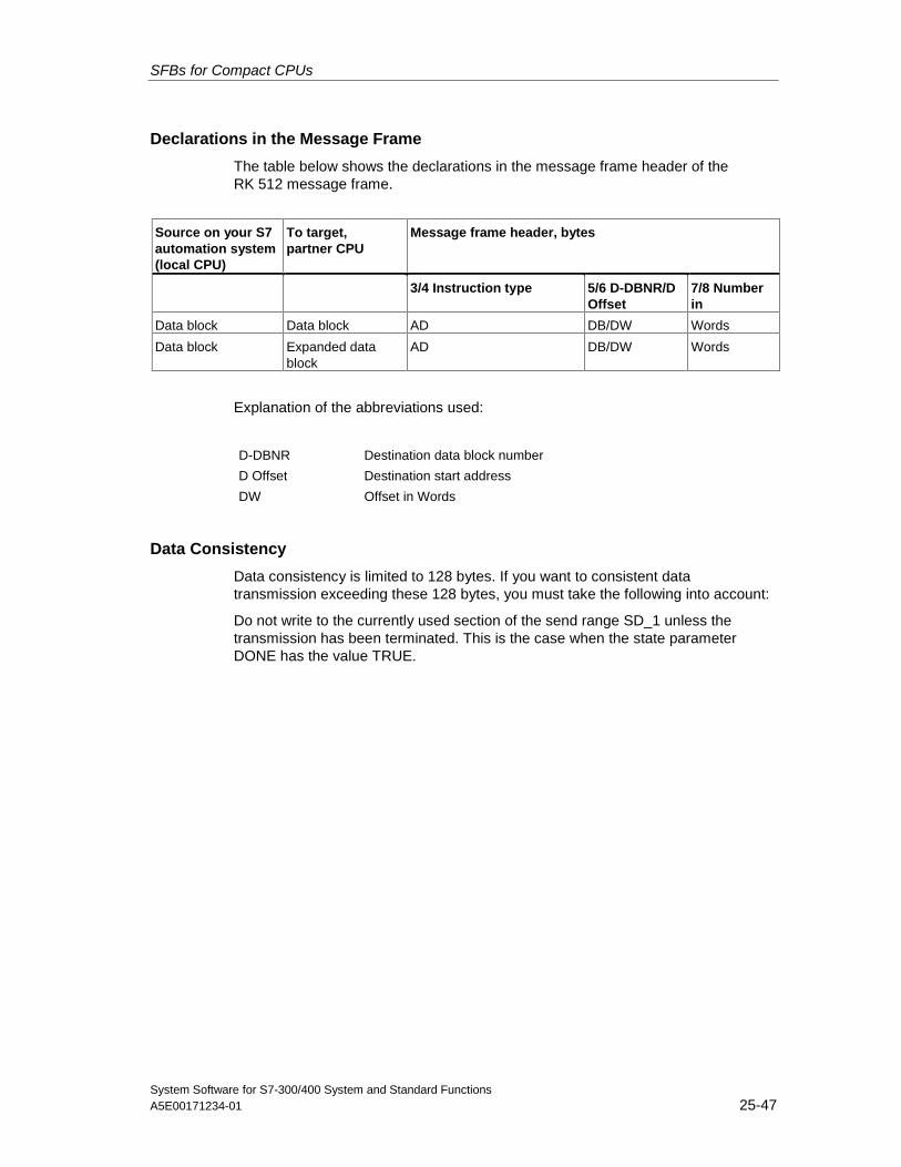
SFBs for Compact CPUs
System Software for S7-300/400 System and Standard FunctionsA5E00171234-01 25-47
Declarations in the Message Frame
The table below shows the declarations in the message frame header of theRK 512 message frame.
Source on your S7automation system(local CPU)
To target,partner CPU
Message frame header, bytes
3/4 Instruction type 5/6 D-DBNR/DOffset
7/8 Numberin
Data block Data block AD DB/DW Words
Data block Expanded datablock
AD DB/DW Words
Explanation of the abbreviations used:
D-DBNR Destination data block number
D Offset Destination start address
DW Offset in Words
Data Consistency
Data consistency is limited to 128 bytes. If you want to consistent datatransmission exceeding these 128 bytes, you must take the following into account:
Do not write to the currently used section of the send range SD_1 unless thetransmission has been terminated. This is the case when the state parameterDONE has the value TRUE.
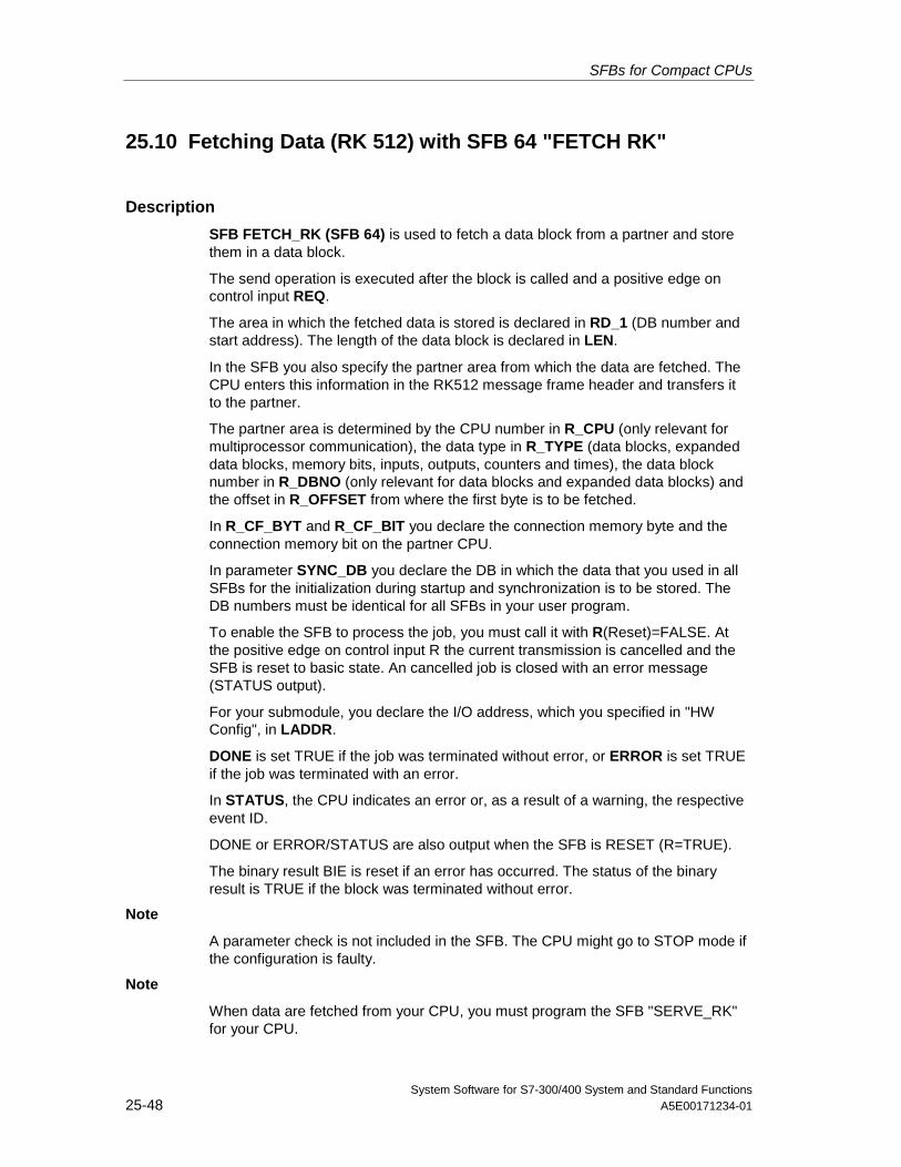
SFBs for Compact CPUs
System Software for S7-300/400 System and Standard Functions25-48 A5E00171234-01
25.10 Fetching Data (RK 512) with SFB 64 "FETCH RK"
Description
SFB FETCH_RK (SFB 64) is used to fetch a data block from a partner and storethem in a data block.
The send operation is executed after the block is called and a positive edge oncontrol input REQ.
The area in which the fetched data is stored is declared in RD_1 (DB number andstart address). The length of the data block is declared in LEN.
In the SFB you also specify the partner area from which the data are fetched. TheCPU enters this information in the RK512 message frame header and transfers itto the partner.
The partner area is determined by the CPU number in R_CPU (only relevant formultiprocessor communication), the data type in R_TYPE (data blocks, expandeddata blocks, memory bits, inputs, outputs, counters and times), the data blocknumber in R_DBNO (only relevant for data blocks and expanded data blocks) andthe offset in R_OFFSET from where the first byte is to be fetched.
In R_CF_BYT and R_CF_BIT you declare the connection memory byte and theconnection memory bit on the partner CPU.
In parameter SYNC_DB you declare the DB in which the data that you used in allSFBs for the initialization during startup and synchronization is to be stored. TheDB numbers must be identical for all SFBs in your user program.
To enable the SFB to process the job, you must call it with R(Reset)=FALSE. Atthe positive edge on control input R the current transmission is cancelled and theSFB is reset to basic state. An cancelled job is closed with an error message(STATUS output).
For your submodule, you declare the I/O address, which you specified in "HWConfig", in LADDR.
DONE is set TRUE if the job was terminated without error, or ERROR is set TRUEif the job was terminated with an error.
In STATUS, the CPU indicates an error or, as a result of a warning, the respectiveevent ID.
DONE or ERROR/STATUS are also output when the SFB is RESET (R=TRUE).
The binary result BIE is reset if an error has occurred. The status of the binaryresult is TRUE if the block was terminated without error.
Note
A parameter check is not included in the SFB. The CPU might go to STOP mode ifthe configuration is faulty.
Note
When data are fetched from your CPU, you must program the SFB "SERVE_RK"for your CPU.
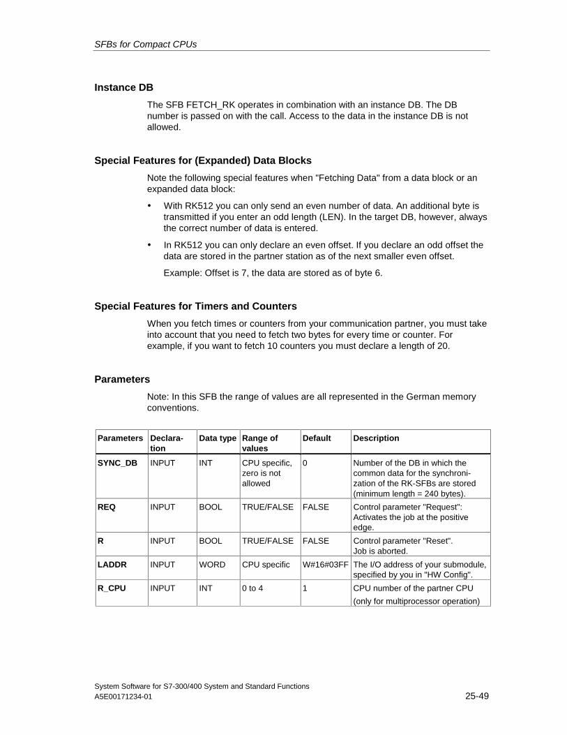
SFBs for Compact CPUs
System Software for S7-300/400 System and Standard FunctionsA5E00171234-01 25-49
Instance DB
The SFB FETCH_RK operates in combination with an instance DB. The DBnumber is passed on with the call. Access to the data in the instance DB is notallowed.
Special Features for (Expanded) Data Blocks
Note the following special features when "Fetching Data" from a data block or anexpanded data block:
• With RK512 you can only send an even number of data. An additional byte istransmitted if you enter an odd length (LEN). In the target DB, however, alwaysthe correct number of data is entered.
• In RK512 you can only declare an even offset. If you declare an odd offset thedata are stored in the partner station as of the next smaller even offset.
Example: Offset is 7, the data are stored as of byte 6.
Special Features for Timers and Counters
When you fetch times or counters from your communication partner, you must takeinto account that you need to fetch two bytes for every time or counter. Forexample, if you want to fetch 10 counters you must declare a length of 20.
Parameters
Note: In this SFB the range of values are all represented in the German memoryconventions.
Parameters Declara-tion
Data type Range ofvalues
Default Description
SYNC_DB INPUT INT CPU specific,zero is notallowed
0 Number of the DB in which thecommon data for the synchroni-zation of the RK-SFBs are stored(minimum length = 240 bytes).
REQ INPUT BOOL TRUE/FALSE FALSE Control parameter "Request":Activates the job at the positiveedge.
R INPUT BOOL TRUE/FALSE FALSE Control parameter "Reset".Job is aborted.
LADDR INPUT WORD CPU specific W#16#03FF The I/O address of your submodule,specified by you in "HW Config".
R_CPU INPUT INT 0 to 4 1 CPU number of the partner CPU
(only for multiprocessor operation)
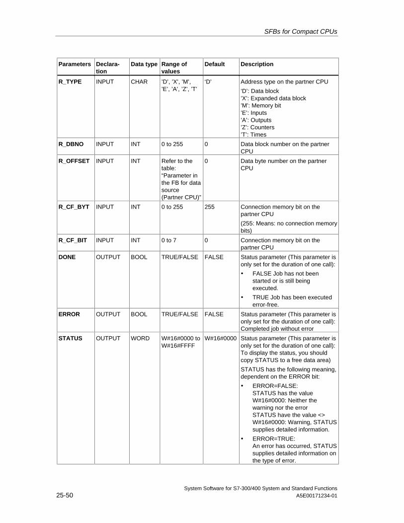
SFBs for Compact CPUs
System Software for S7-300/400 System and Standard Functions25-50 A5E00171234-01
Parameters Declara-tion
Data type Range ofvalues
Default Description
R_TYPE INPUT CHAR ’D’, ’X’, ’M’,’E’, ’A’, ’Z’, ’T’
‘D’ Address type on the partner CPU
‘D’: Data block’X’: Expanded data block’M’: Memory bit’E’: Inputs’A’: Outputs’Z’: Counters’T’: Times
R_DBNO INPUT INT 0 to 255 0 Data block number on the partnerCPU
R_OFFSET INPUT INT Refer to thetable:“Parameter inthe FB for datasource(Partner CPU)”
0 Data byte number on the partnerCPU
R_CF_BYT INPUT INT 0 to 255 255 Connection memory bit on thepartner CPU
(255: Means: no connection memorybits)
R_CF_BIT INPUT INT 0 to 7 0 Connection memory bit on thepartner CPU
DONE OUTPUT BOOL TRUE/FALSE FALSE Status parameter (This parameter isonly set for the duration of one call):
• FALSE Job has not beenstarted or is still beingexecuted.
• TRUE Job has been executederror-free.
ERROR OUTPUT BOOL TRUE/FALSE FALSE Status parameter (This parameter isonly set for the duration of one call):Completed job without error
STATUS OUTPUT WORD W#16#0000 toW#16#FFFF
W#16#0000 Status parameter (This parameter isonly set for the duration of one call):To display the status, you shouldcopy STATUS to a free data area)
STATUS has the following meaning,dependent on the ERROR bit:
• ERROR=FALSE:STATUS has the valueW#16#0000: Neither thewarning nor the errorSTATUS have the value <>W#16#0000: Warning, STATUSsupplies detailed information.
• ERROR=TRUE:An error has occurred, STATUSsupplies detailed information onthe type of error.
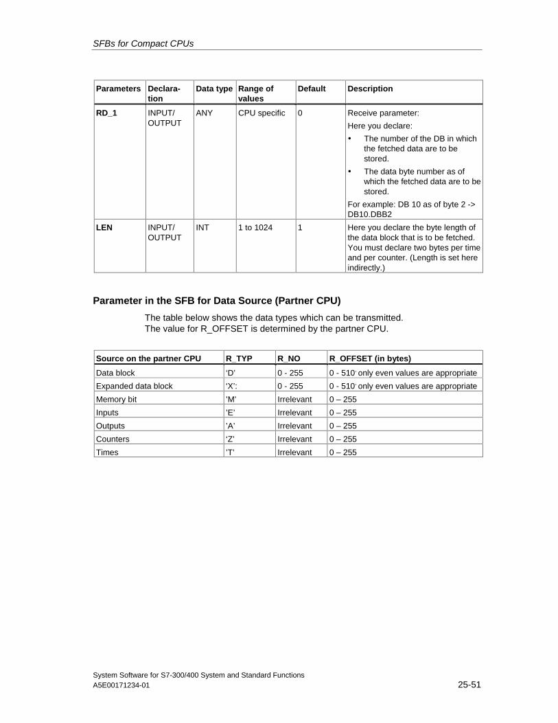
SFBs for Compact CPUs
System Software for S7-300/400 System and Standard FunctionsA5E00171234-01 25-51
Parameters Declara-tion
Data type Range ofvalues
Default Description
RD_1 INPUT/OUTPUT
ANY CPU specific 0 Receive parameter:
Here you declare:
• The number of the DB in whichthe fetched data are to bestored.
• The data byte number as ofwhich the fetched data are to bestored.
For example: DB 10 as of byte 2 ->DB10.DBB2
LEN INPUT/OUTPUT
INT 1 to 1024 1 Here you declare the byte length ofthe data block that is to be fetched.You must declare two bytes per timeand per counter. (Length is set hereindirectly.)
Parameter in the SFB for Data Source (Partner CPU)
The table below shows the data types which can be transmitted.The value for R_OFFSET is determined by the partner CPU.
Source on the partner CPU R_TYP R_NO R_OFFSET (in bytes)
Data block ‘D’ 0 - 255 0 - 510, only even values are appropriate
Expanded data block ‘X’: 0 - 255 0 - 510, only even values are appropriate
Memory bit ’M’ Irrelevant 0 – 255
Inputs ’E’ Irrelevant 0 – 255
Outputs ’A’ Irrelevant 0 – 255
Counters ‘Z’ Irrelevant 0 – 255
Times ’T’ Irrelevant 0 – 255
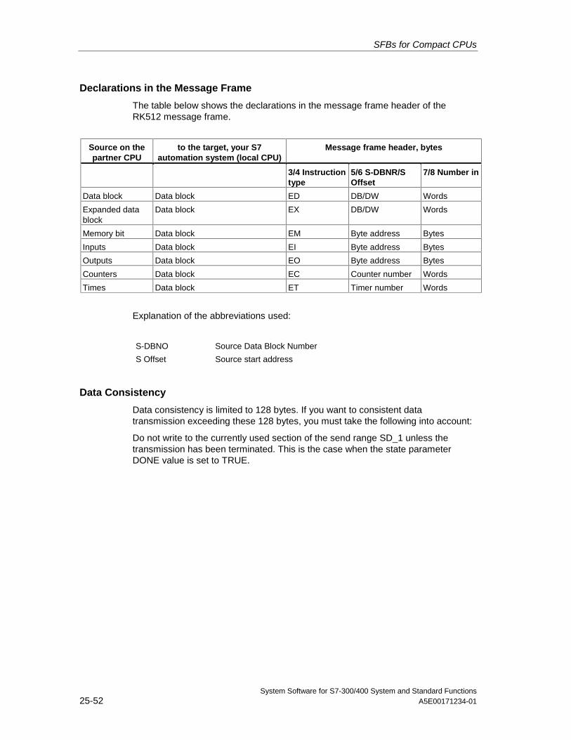
SFBs for Compact CPUs
System Software for S7-300/400 System and Standard Functions25-52 A5E00171234-01
Declarations in the Message Frame
The table below shows the declarations in the message frame header of theRK512 message frame.
Source on thepartner CPU
to the target, your S7automation system (local CPU)
Message frame header, bytes
3/4 Instructiontype
5/6 S-DBNR/SOffset
7/8 Number in
Data block Data block ED DB/DW Words
Expanded datablock
Data block EX DB/DW Words
Memory bit Data block EM Byte address Bytes
Inputs Data block EI Byte address Bytes
Outputs Data block EO Byte address Bytes
Counters Data block EC Counter number Words
Times Data block ET Timer number Words
Explanation of the abbreviations used:
S-DBNO Source Data Block Number
S Offset Source start address
Data Consistency
Data consistency is limited to 128 bytes. If you want to consistent datatransmission exceeding these 128 bytes, you must take the following into account:
Do not write to the currently used section of the send range SD_1 unless thetransmission has been terminated. This is the case when the state parameterDONE value is set to TRUE.
SFBs for Compact CPUs
System Software for S7-300/400 System and Standard FunctionsA5E00171234-01 25-53
25.11 Receiving and Providing Data (RK 512) with SFB 65"SERVE_RK"
Description
Use the SFB SERVE_RK (SFB 65) to receive and provide data.
• Receiving data: The data are stored in the area that is specified by the partnerin the RK512 message frame header. A call of the SFB is required when thecommunication partner executes a "Send Data" (SEND jobs) job.
• Providing Data: The data are fetched from the area that is specified by thepartner in the RK512 message frame header. A call of the SFB is requiredwhen the communication partner executes a "Fetch Data" (FETCH jobs) job.
The block is ready to after it is called with the control input EN_R value TRUE. Youcan cancel the current transmission by setting the signal status of parameter EN_Rto FALSE. A cancelled job is terminated with an error message (STATUS output).The input is switched off as long as the signal status of parameter EN_R is set toFALSE.
In parameter SYNC_DB you declare the DB in which the data that is used by youin all SFBs for the initialization during startup and synchronization is to be stored.The DB numbers must be identical for all SFBs in your user program.
To enable the SFB to process the job, you must call it with R(Reset)=FALSE. Atthe positive edge on control input R the current transmission is cancelled and theSFB is reset to basic state. A cancelled job is terminated with an error message(STATUS output).
For your submodule, you declare the I/O address, which was specified by you in"HW Config", in LADDR.
NDR is set TRUE if the job was terminated without error, or ERROR is set TRUE ifthe job was terminated with an error.
With NDR=TRUE for an SFB call the CPU indicates in the parameters L_TYPE,L_DBNO and L_OFFSET the area where data were stored or fetched from. Alsoshown for a call are the parameters L_CF_BYT and L_CF_BIT and the length LENof the respective job.
In STATUS, the CPU indicates an error or, as a result of a warning, the respectiveevent ID (refer to the appendix).
NDR or ERROR/STATUS are also output (parameter LEN == 16#00) when theSFB is RESET (R=TRUE).
• The binary result BIE is reset if an error has occurred. The status of the binaryresult is TRUE if the block was terminated without error.
Note
A parameter check is not included in the SFB. The CPU might go to STOP mode ifthe configuration is faulty.
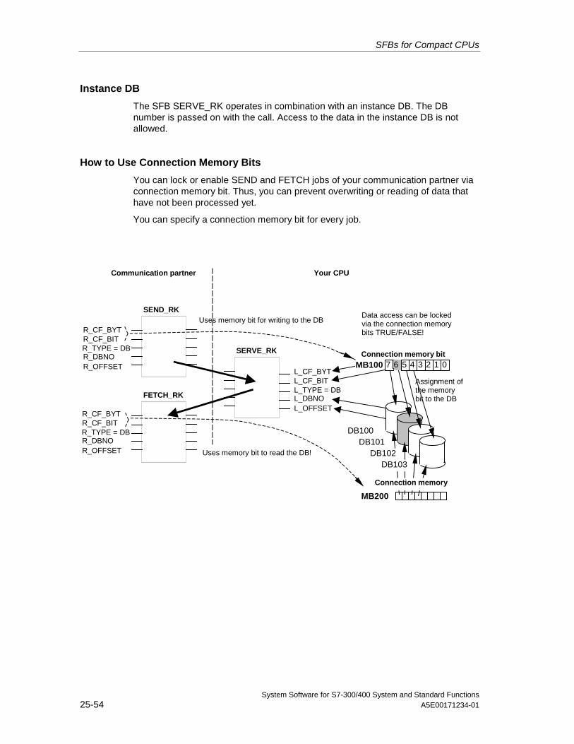
SFBs for Compact CPUs
System Software for S7-300/400 System and Standard Functions25-54 A5E00171234-01
Instance DB
The SFB SERVE_RK operates in combination with an instance DB. The DBnumber is passed on with the call. Access to the data in the instance DB is notallowed.
How to Use Connection Memory Bits
You can lock or enable SEND and FETCH jobs of your communication partner viaconnection memory bit. Thus, you can prevent overwriting or reading of data thathave not been processed yet.
You can specify a connection memory bit for every job.
Connection memory bit
DB100
MB100 L_CF_BYT L_CF_BIT L_TYPE = DB L_DBNO L_OFFSET
SERVE_RK
Data access can be lockedvia the connection memorybits TRUE/FALSE!
SEND_RK
FETCH_RK
R_CF_BYT R_CF_BIT R_TYPE = DB R_DBNO R_OFFSET
R_CF_BYT R_CF_BIT R_TYPE = DB R_DBNO R_OFFSET
Assignment ofthe memorybit to the DB
Uses memory bit for writing to the DB
MB200
Connection memory
DB101DB102
DB103Uses memory bit to read the DB!
Communication partner Your CPU
7 6 5 4 3 2 1 0
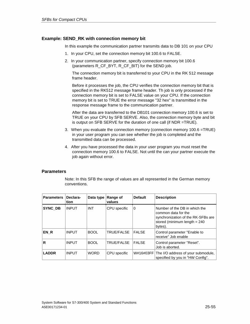
SFBs for Compact CPUs
System Software for S7-300/400 System and Standard FunctionsA5E00171234-01 25-55
Example: SEND_RK with connection memory bit
In this example the communication partner transmits data to DB 101 on your CPU
1. In your CPU, set the connection memory bit 100.6 to FALSE.
2. In your communication partner, specify connection memory bit 100.6(parameters R_CF_BYT, R_CF_BIT) for the SEND job.
The connection memory bit is transferred to your CPU in the RK 512 messageframe header.
Before it processes the job, the CPU verifies the connection memory bit that isspecified in the RK512 message frame header. Th job is only processed if theconnection memory bit is set to FALSE value on your CPU. If the connectionmemory bit is set to TRUE the error message "32 hex" is transmitted in theresponse message frame to the communication partner.
After the data are transferred to the DB101 connection memory 100.6 is set toTRUE on your CPU by SFB SERVE. Also, the connection memory byte and bitis output on SFB SERVE for the duration of one call (if NDR =TRUE).
3. When you evaluate the connection memory (connection memory 100.6 =TRUE)in your user program you can see whether the job is completed and thetransmitted data can be processed.
4. After you have processed the data in your user program you must reset theconnection memory 100.6 to FALSE. Not until the can your partner execute thejob again without error.
Parameters
Note: In this SFB the range of values are all represented in the German memoryconventions.
Parameters Declara-tion
Data type Range ofvalues
Default Description
SYNC_DB INPUT INT CPU specific 0 Number of the DB in which thecommon data for thesynchronization of the RK-SFBs arestored (minimum length = 240bytes).
EN_R INPUT BOOL TRUE/FALSE FALSE Control parameter "Enable toreceive" Job enable
R INPUT BOOL TRUE/FALSE FALSE Control parameter "Reset".Job is aborted.
LADDR INPUT WORD CPU specific W#16#03FF The I/O address of your submodule,specified by you in "HW Config".
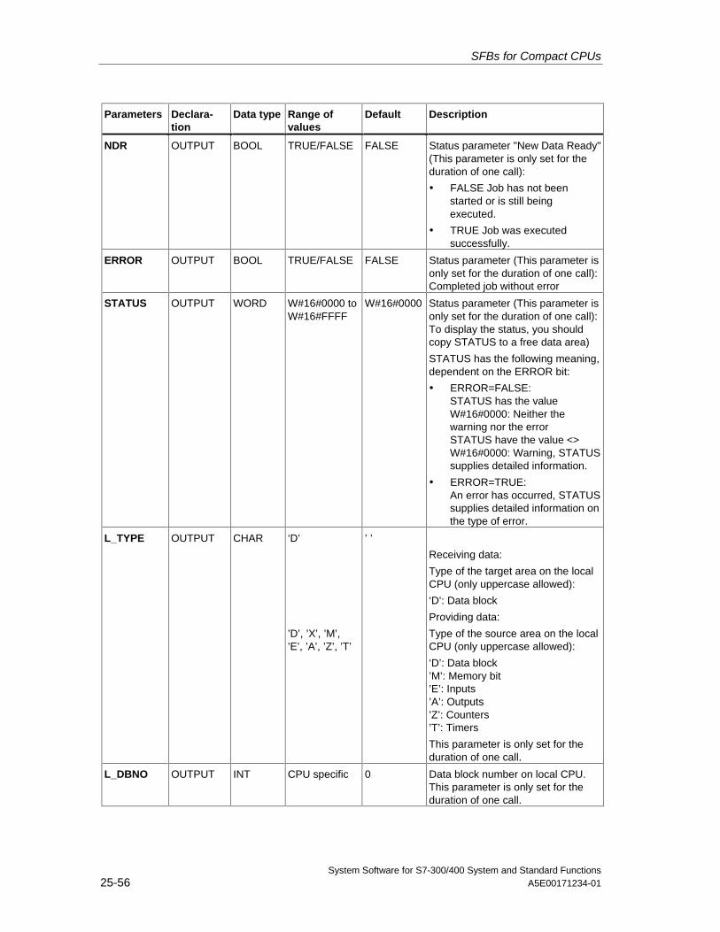
SFBs for Compact CPUs
System Software for S7-300/400 System and Standard Functions25-56 A5E00171234-01
Parameters Declara-tion
Data type Range ofvalues
Default Description
NDR OUTPUT BOOL TRUE/FALSE FALSE Status parameter "New Data Ready"(This parameter is only set for theduration of one call):
• FALSE Job has not beenstarted or is still beingexecuted.
• TRUE Job was executedsuccessfully.
ERROR OUTPUT BOOL TRUE/FALSE FALSE Status parameter (This parameter isonly set for the duration of one call):Completed job without error
STATUS OUTPUT WORD W#16#0000 toW#16#FFFF
W#16#0000 Status parameter (This parameter isonly set for the duration of one call):To display the status, you shouldcopy STATUS to a free data area)
STATUS has the following meaning,dependent on the ERROR bit:
• ERROR=FALSE:STATUS has the valueW#16#0000: Neither thewarning nor the errorSTATUS have the value <>W#16#0000: Warning, STATUSsupplies detailed information.
• ERROR=TRUE:An error has occurred, STATUSsupplies detailed information onthe type of error.
L_TYPE OUTPUT CHAR ‘D’
’D’, ’X’, ’M’,’E’, ’A’, ’Z’, ’T’
’ ’
Receiving data:
Type of the target area on the localCPU (only uppercase allowed):
‘D’: Data block
Providing data:
Type of the source area on the localCPU (only uppercase allowed):
‘D’: Data block’M’: Memory bit’E’: Inputs’A’: Outputs’Z’: Counters’T’: Timers
This parameter is only set for theduration of one call.
L_DBNO OUTPUT INT CPU specific 0 Data block number on local CPU.This parameter is only set for theduration of one call.
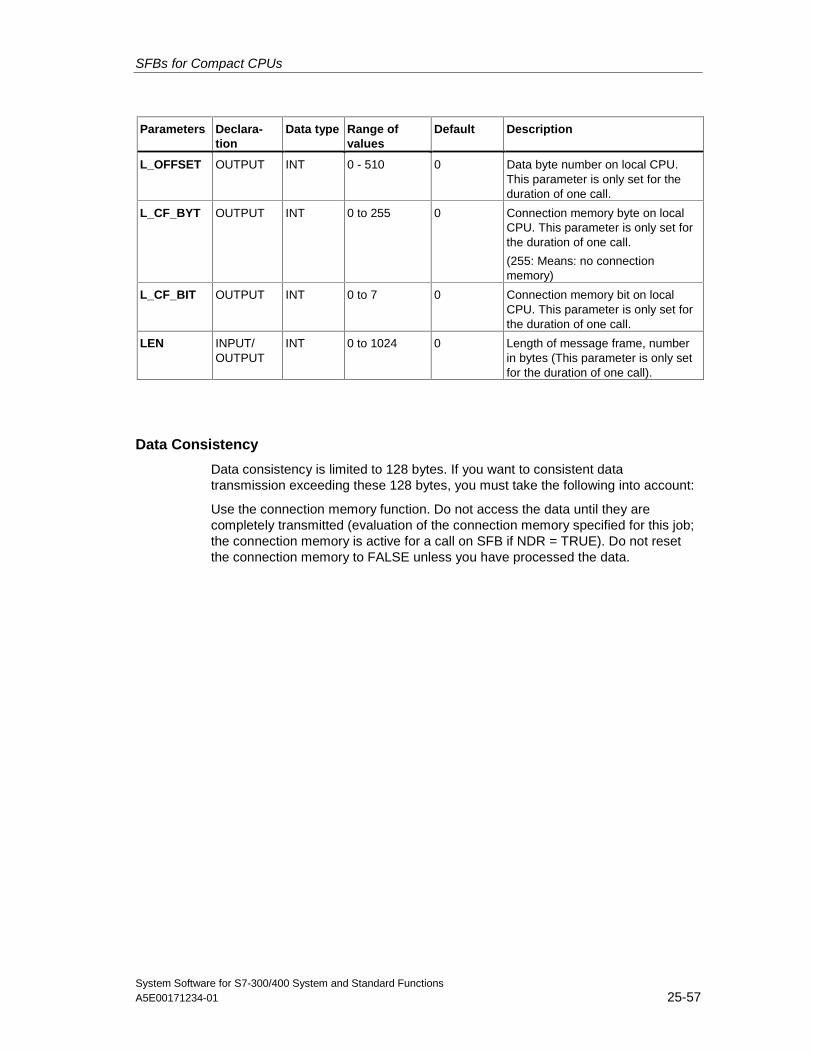
SFBs for Compact CPUs
System Software for S7-300/400 System and Standard FunctionsA5E00171234-01 25-57
Parameters Declara-tion
Data type Range ofvalues
Default Description
L_OFFSET OUTPUT INT 0 - 510 0 Data byte number on local CPU.This parameter is only set for theduration of one call.
L_CF_BYT OUTPUT INT 0 to 255 0 Connection memory byte on localCPU. This parameter is only set forthe duration of one call.
(255: Means: no connectionmemory)
L_CF_BIT OUTPUT INT 0 to 7 0 Connection memory bit on localCPU. This parameter is only set forthe duration of one call.
LEN INPUT/OUTPUT
INT 0 to 1024 0 Length of message frame, numberin bytes (This parameter is only setfor the duration of one call).
Data Consistency
Data consistency is limited to 128 bytes. If you want to consistent datatransmission exceeding these 128 bytes, you must take the following into account:
Use the connection memory function. Do not access the data until they arecompletely transmitted (evaluation of the connection memory specified for this job;the connection memory is active for a call on SFB if NDR = TRUE). Do not resetthe connection memory to FALSE unless you have processed the data.
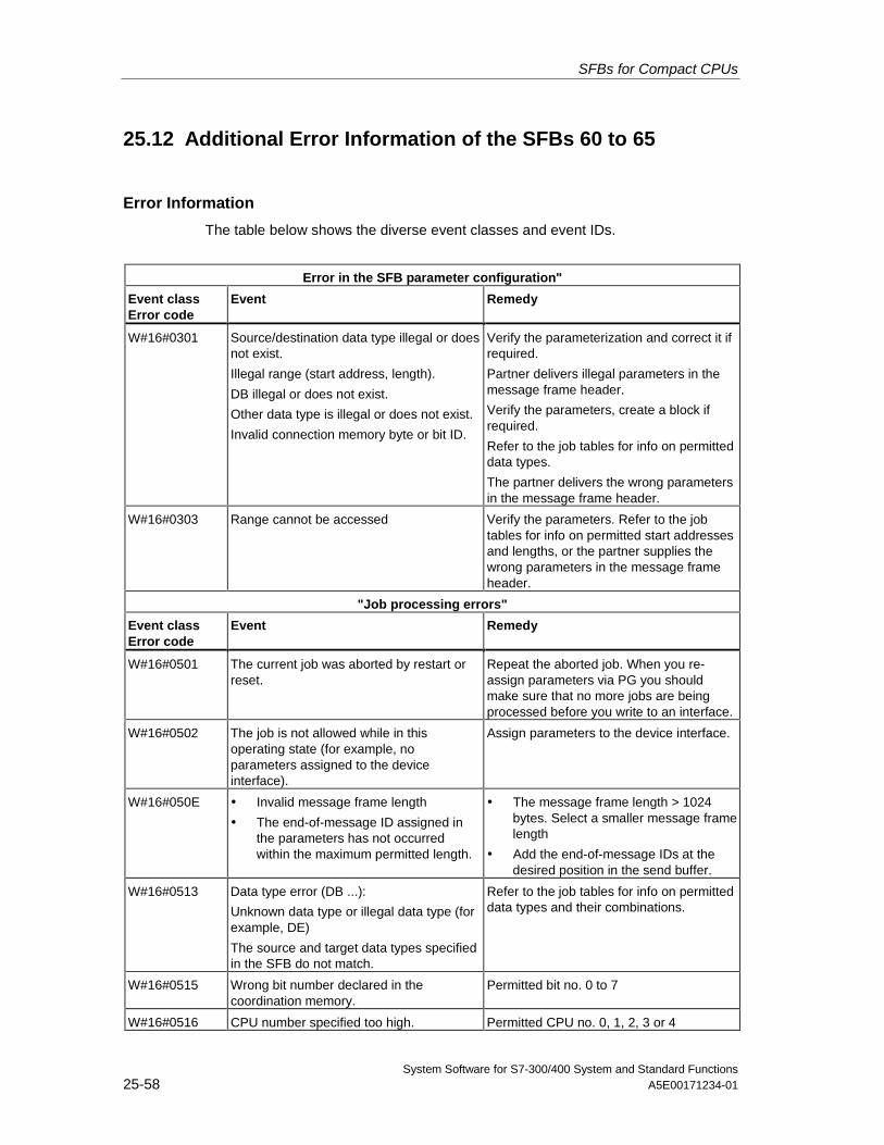
SFBs for Compact CPUs
System Software for S7-300/400 System and Standard Functions25-58 A5E00171234-01
25.12 Additional Error Information of the SFBs 60 to 65
Error Information
The table below shows the diverse event classes and event IDs.
Error in the SFB parameter configuration"
Event classError code
Event Remedy
W#16#0301 Source/destination data type illegal or doesnot exist.
Illegal range (start address, length).
DB illegal or does not exist.
Other data type is illegal or does not exist.
Invalid connection memory byte or bit ID.
Verify the parameterization and correct it ifrequired.
Partner delivers illegal parameters in themessage frame header.
Verify the parameters, create a block ifrequired.
Refer to the job tables for info on permitteddata types.
The partner delivers the wrong parametersin the message frame header.
W#16#0303 Range cannot be accessed Verify the parameters. Refer to the jobtables for info on permitted start addressesand lengths, or the partner supplies thewrong parameters in the message frameheader.
"Job processing errors"
Event classError code
Event Remedy
W#16#0501 The current job was aborted by restart orreset.
Repeat the aborted job. When you re-assign parameters via PG you shouldmake sure that no more jobs are beingprocessed before you write to an interface.
W#16#0502 The job is not allowed while in thisoperating state (for example, noparameters assigned to the deviceinterface).
Assign parameters to the device interface.
W#16#050E • Invalid message frame length
• The end-of-message ID assigned inthe parameters has not occurredwithin the maximum permitted length.
• The message frame length > 1024bytes. Select a smaller message framelength
• Add the end-of-message IDs at thedesired position in the send buffer.
W#16#0513 Data type error (DB ...):
Unknown data type or illegal data type (forexample, DE)
The source and target data types specifiedin the SFB do not match.
Refer to the job tables for info on permitteddata types and their combinations.
W#16#0515 Wrong bit number declared in thecoordination memory.
Permitted bit no. 0 to 7
W#16#0516 CPU number specified too high. Permitted CPU no. 0, 1, 2, 3 or 4
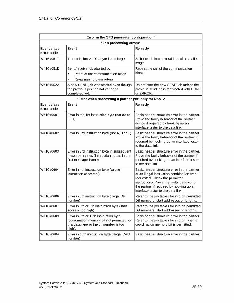
SFBs for Compact CPUs
System Software for S7-300/400 System and Standard FunctionsA5E00171234-01 25-59
Error in the SFB parameter configuration"
"Job processing errors"
Event classError code
Event Remedy
W#16#0517 Transmission > 1024 byte is too large Split the job into several jobs of a smallerlength.
W#16#051D Send/receive job aborted by
• Reset of the communication block
• Re-assigning parameters
Repeat the call of the communicationblock.
W#16#0522 A new SEND job was started even thoughthe previous job has not yet beencompleted yet.
Do not start the new SEND job unless theprevious send job is terminated with DONEor ERROR.
"Error when processing a partner job" only for RK512
Event classError code
Event Remedy
W#16#0601 Error in the 1st instruction byte (not 00 orFFH)
Basic header structure error in the partner.Prove the faulty behavior of the partnerdevice if required by hooking up aninterface tester to the data link.
W#16#0602 Error in 3rd instruction byte (not A, 0 or E) Basic header structure error in the partner.Prove the faulty behavior of the partner ifrequired by hooking up an interface testerto the data link.
W#16#0603 Error in 3rd instruction byte in subsequentmessage frames (instruction not as in thefirst message frame)
Basic header structure error in the partner.Prove the faulty behavior of the partner ifrequired by hooking up an interface testerto the data link.
W#16#0604 Error in 4th instruction byte (wronginstruction character)
Basic header structure error in the partneror an illegal instruction combination wasrequested. Check the permittedinstructions. Prove the faulty behavior ofthe partner if required by hooking up aninterface tester to the data link.
W#16#0606 Error in 5th instruction byte (illegal DBnumber)
Refer to the job tables for info on permittedDB numbers, start addresses or lengths.
W#16#0607 Error in 5th or 6th instruction byte (startaddress too high)
Refer to the job tables for info on permittedDB numbers, start addresses or lengths.
W#16#0609 Error in 9th or 10th instruction byte(coordination memory bit not permitted forthis data type or the bit number is toohigh).
Basic header structure error in the partner.Refer to the job tables for info on when acoordination memory bit is permitted.
W#16#060A Error in 10th instruction byte (illegal CPUnumber)
Basic header structure error in the partner.
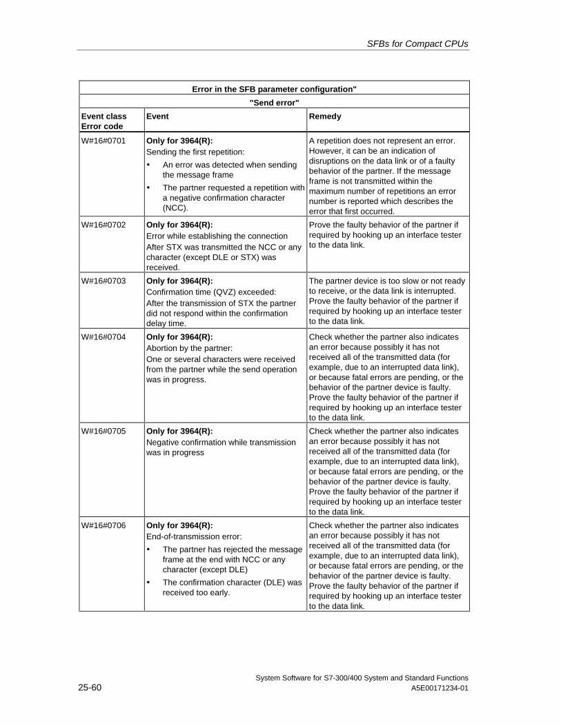
SFBs for Compact CPUs
System Software for S7-300/400 System and Standard Functions25-60 A5E00171234-01
Error in the SFB parameter configuration"
"Send error"
Event classError code
Event Remedy
W#16#0701 Only for 3964(R):Sending the first repetition:
• An error was detected when sendingthe message frame
• The partner requested a repetition witha negative confirmation character(NCC).
A repetition does not represent an error.However, it can be an indication ofdisruptions on the data link or of a faultybehavior of the partner. If the messageframe is not transmitted within themaximum number of repetitions an errornumber is reported which describes theerror that first occurred.
W#16#0702 Only for 3964(R):Error while establishing the connectionAfter STX was transmitted the NCC or anycharacter (except DLE or STX) wasreceived.
Prove the faulty behavior of the partner ifrequired by hooking up an interface testerto the data link.
W#16#0703 Only for 3964(R):Confirmation time (QVZ) exceeded:After the transmission of STX the partnerdid not respond within the confirmationdelay time.
The partner device is too slow or not readyto receive, or the data link is interrupted.Prove the faulty behavior of the partner ifrequired by hooking up an interface testerto the data link.
W#16#0704 Only for 3964(R):Abortion by the partner:One or several characters were receivedfrom the partner while the send operationwas in progress.
Check whether the partner also indicatesan error because possibly it has notreceived all of the transmitted data (forexample, due to an interrupted data link),or because fatal errors are pending, or thebehavior of the partner device is faulty.Prove the faulty behavior of the partner ifrequired by hooking up an interface testerto the data link.
W#16#0705 Only for 3964(R):Negative confirmation while transmissionwas in progress
Check whether the partner also indicatesan error because possibly it has notreceived all of the transmitted data (forexample, due to an interrupted data link),or because fatal errors are pending, or thebehavior of the partner device is faulty.Prove the faulty behavior of the partner ifrequired by hooking up an interface testerto the data link.
W#16#0706 Only for 3964(R):End-of-transmission error:
• The partner has rejected the messageframe at the end with NCC or anycharacter (except DLE)
• The confirmation character (DLE) wasreceived too early.
Check whether the partner also indicatesan error because possibly it has notreceived all of the transmitted data (forexample, due to an interrupted data link),or because fatal errors are pending, or thebehavior of the partner device is faulty.Prove the faulty behavior of the partner ifrequired by hooking up an interface testerto the data link.
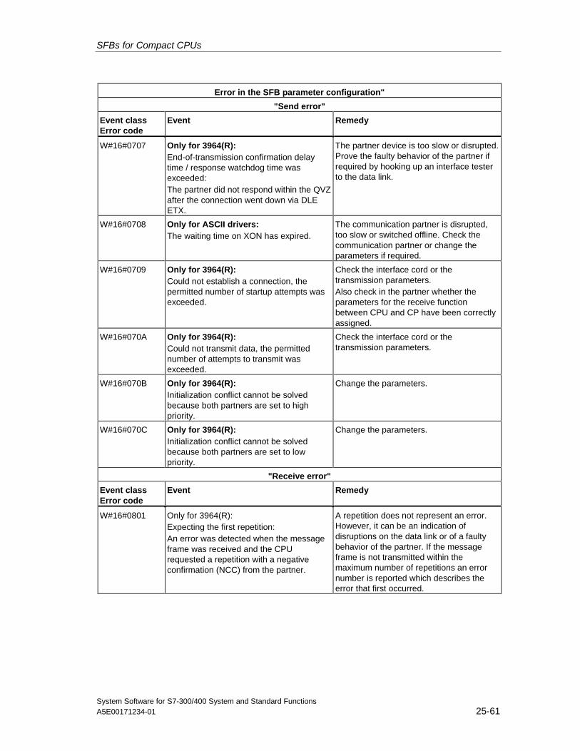
SFBs for Compact CPUs
System Software for S7-300/400 System and Standard FunctionsA5E00171234-01 25-61
Error in the SFB parameter configuration"
"Send error"
Event classError code
Event Remedy
W#16#0707 Only for 3964(R):End-of-transmission confirmation delaytime / response watchdog time wasexceeded:The partner did not respond within the QVZafter the connection went down via DLEETX.
The partner device is too slow or disrupted.Prove the faulty behavior of the partner ifrequired by hooking up an interface testerto the data link.
W#16#0708 Only for ASCII drivers:The waiting time on XON has expired.
The communication partner is disrupted,too slow or switched offline. Check thecommunication partner or change theparameters if required.
W#16#0709 Only for 3964(R):Could not establish a connection, thepermitted number of startup attempts wasexceeded.
Check the interface cord or thetransmission parameters.Also check in the partner whether theparameters for the receive functionbetween CPU and CP have been correctlyassigned.
W#16#070A Only for 3964(R):Could not transmit data, the permittednumber of attempts to transmit wasexceeded.
Check the interface cord or thetransmission parameters.
W#16#070B Only for 3964(R):Initialization conflict cannot be solvedbecause both partners are set to highpriority.
Change the parameters.
W#16#070C Only for 3964(R):Initialization conflict cannot be solvedbecause both partners are set to lowpriority.
Change the parameters.
"Receive error"
Event classError code
Event Remedy
W#16#0801 Only for 3964(R):Expecting the first repetition:An error was detected when the messageframe was received and the CPUrequested a repetition with a negativeconfirmation (NCC) from the partner.
A repetition does not represent an error.However, it can be an indication ofdisruptions on the data link or of a faultybehavior of the partner. If the messageframe is not transmitted within themaximum number of repetitions an errornumber is reported which describes theerror that first occurred.
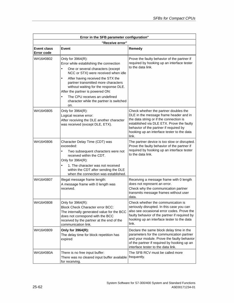
SFBs for Compact CPUs
System Software for S7-300/400 System and Standard Functions25-62 A5E00171234-01
Error in the SFB parameter configuration"
"Receive error"
Event classError code
Event Remedy
W#16#0802 Only for 3964(R):Error while establishing the connection
• One or several characters (exceptNCC or STX) were received when idle
• After having received the STX thepartner transmitted more characterswithout waiting for the response DLE.
After the partner is powered ON:
• The CPU receives an undefinedcharacter while the partner is switchedon.
Prove the faulty behavior of the partner ifrequired by hooking up an interface testerto the data link.
W#16#0805 Only for 3964(R):Logical receive error:After receiving the DLE another characterwas received (except DLE, ETX).
Check whether the partner doubles theDLE in the message frame header and inthe data string or if the connection isestablished via DLE ETX. Prove the faultybehavior of the partner if required byhooking up an interface tester to the datalink.
W#16#0806 Character Delay Time (CDT) wasexceeded:
• Two subsequent characters were notreceived within the CDT.
Only for 3964(R):
• 1. The character was not receivedwithin the CDT after sending the DLEwhen the connection was established.
The partner device is too slow or disrupted.Prove the faulty behavior of the partner ifrequired by hooking up an interface testerto the data link.
W#16#0807 Illegal message frame length:A message frame with 0 length wasreceived.
Receiving a message frame with 0 lengthdoes not represent an error.Check why the communication partnertransmits message frames without userdata.
W#16#0808 Only for 3964(R):Block Check Character error BCC:The internally generated value for the BCCdoes not correspond with the BCCreceived by the partner at the end of thecommunication link.
Check whether the communication isseriously disrupted. In this case you canalso see occasional error codes. Prove thefaulty behavior of the partner if required byhooking up an interface tester to the datalink.
W#16#0809 Only for 3964(R):The delay time for block repetition hasexpired
Declare the same block delay time in theparameters for the communication partnerand your module. Prove the faulty behaviorof the partner if required by hooking up aninterface tester to the data link.
W#16#080A There is no free input buffer:There was no cleared input buffer availablefor receiving.
The SFB RCV must be called morefrequently.
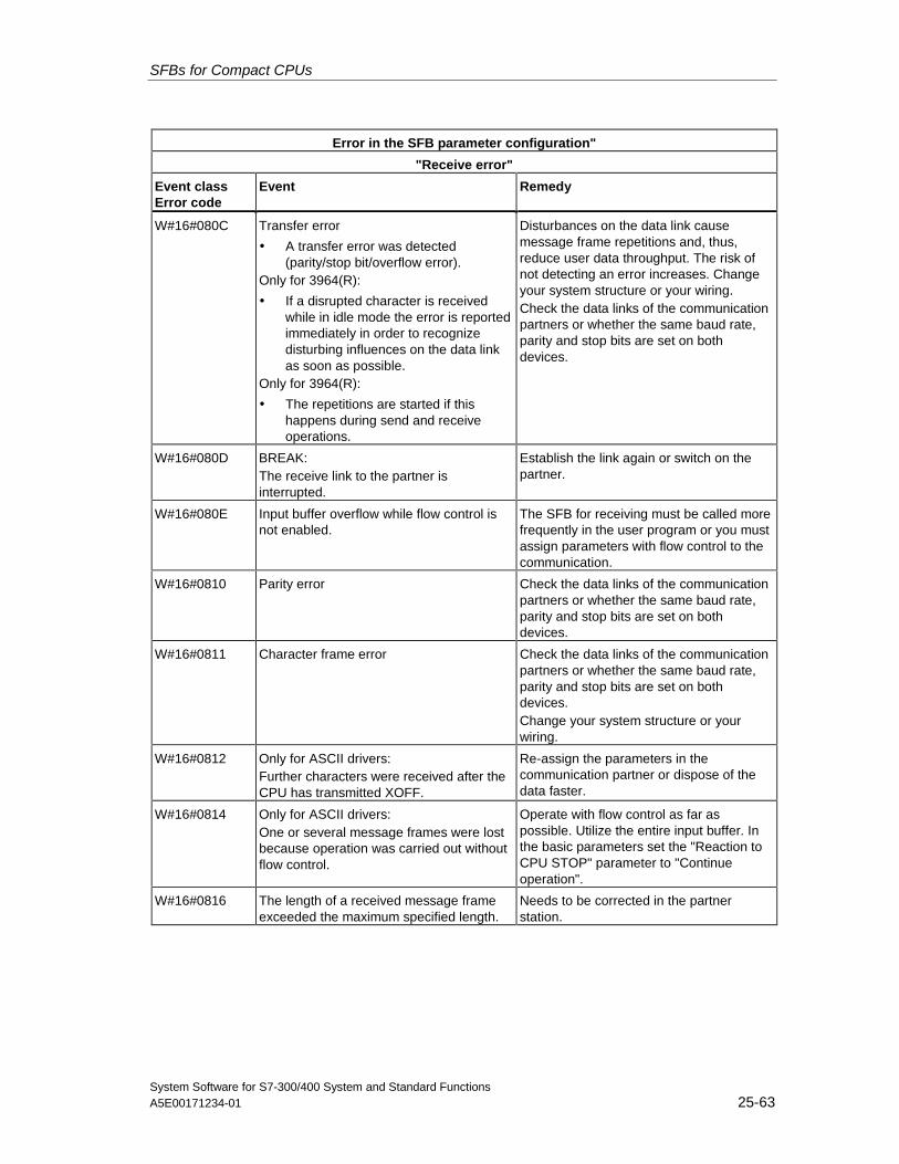
SFBs for Compact CPUs
System Software for S7-300/400 System and Standard FunctionsA5E00171234-01 25-63
Error in the SFB parameter configuration"
"Receive error"
Event classError code
Event Remedy
W#16#080C Transfer error
• A transfer error was detected(parity/stop bit/overflow error).
Only for 3964(R):
• If a disrupted character is receivedwhile in idle mode the error is reportedimmediately in order to recognizedisturbing influences on the data linkas soon as possible.
Only for 3964(R):
• The repetitions are started if thishappens during send and receiveoperations.
Disturbances on the data link causemessage frame repetitions and, thus,reduce user data throughput. The risk ofnot detecting an error increases. Changeyour system structure or your wiring.Check the data links of the communicationpartners or whether the same baud rate,parity and stop bits are set on bothdevices.
W#16#080D BREAK:The receive link to the partner isinterrupted.
Establish the link again or switch on thepartner.
W#16#080E Input buffer overflow while flow control isnot enabled.
The SFB for receiving must be called morefrequently in the user program or you mustassign parameters with flow control to thecommunication.
W#16#0810 Parity error Check the data links of the communicationpartners or whether the same baud rate,parity and stop bits are set on bothdevices.
W#16#0811 Character frame error Check the data links of the communicationpartners or whether the same baud rate,parity and stop bits are set on bothdevices.Change your system structure or yourwiring.
W#16#0812 Only for ASCII drivers:Further characters were received after theCPU has transmitted XOFF.
Re-assign the parameters in thecommunication partner or dispose of thedata faster.
W#16#0814 Only for ASCII drivers:One or several message frames were lostbecause operation was carried out withoutflow control.
Operate with flow control as far aspossible. Utilize the entire input buffer. Inthe basic parameters set the "Reaction toCPU STOP" parameter to "Continueoperation".
W#16#0816 The length of a received message frameexceeded the maximum specified length.
Needs to be corrected in the partnerstation.
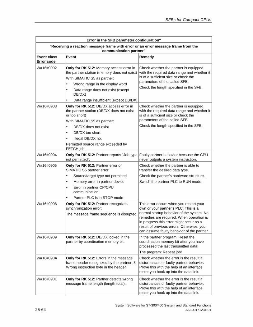
SFBs for Compact CPUs
System Software for S7-300/400 System and Standard Functions25-64 A5E00171234-01
Error in the SFB parameter configuration"
"Receiving a reaction message frame with error or an error message frame from thecommunication partner"
Event classError code
Event Remedy
W#16#0902 Only for RK 512: Memory access error inthe partner station (memory does not exist)
With SIMATIC S5 as partner:
• Wrong range in the display word
• Data range does not exist (exceptDB/DX)
• Data range insufficient (except DB/DX)
Check whether the partner is equippedwith the required data range and whether itis of a sufficient size or check theparameters of the called SFB.
Check the length specified in the SFB.
W#16#0903 Only for RK 512: DB/DX access error inthe partner station (DB/DX does not existor too short)
With SIMATIC S5 as partner:
• DB/DX does not exist
• DB/DX too short
• Illegal DB/DX no.
Permitted source range exceeded byFETCH job.
Check whether the partner is equippedwith the required data range and whether itis of a sufficient size or check theparameters of the called SFB.
Check the length specified in the SFB.
W#16#0904 Only for RK 512: Partner reports “Job typenot permitted”.
Faulty partner behavior because the CPUnever outputs a system instruction.
W#16#0905 Only for RK 512: Partner error orSIMATIC S5 partner error:
• Source/target type not permitted
• Memory error in partner device
• Error in partner CP/CPUcommunication
• Partner PLC is in STOP mode
Check whether the partner is able totransfer the desired data type.
Check the partner’s hardware structure.
Switch the partner PLC to RUN mode.
W#16#0908 Only for RK 512: Partner recognizessynchronization error:
The message frame sequence is disrupted.
This error occurs when you restart yourown or your partner’s PLC. This is anormal startup behavior of the system. Noremedies are required. When operation isin progress this error might occur as aresult of previous errors. Otherwise, youcan assume faulty behavior of the partner.
W#16#0909 Only for RK 512: DB/DX locked in thepartner by coordination memory bit.
In the partner program: Reset thecoordination memory bit after you haveprocessed the last transmitted data!
The program: Repeat job!
W#16#090A Only for RK 512: Errors in the messageframe header recognized by the partner: 3.Wrong instruction byte in the header
Check whether the error is the result ifdisturbances or faulty partner behavior.Prove this with the help of an interfacetester you hook up into the data link.
W#16#090C Only for RK 512: Partner detects wrongmessage frame length (length total).
Check whether the error is the result ifdisturbances or faulty partner behavior.Prove this with the help of an interfacetester you hook up into the data link.
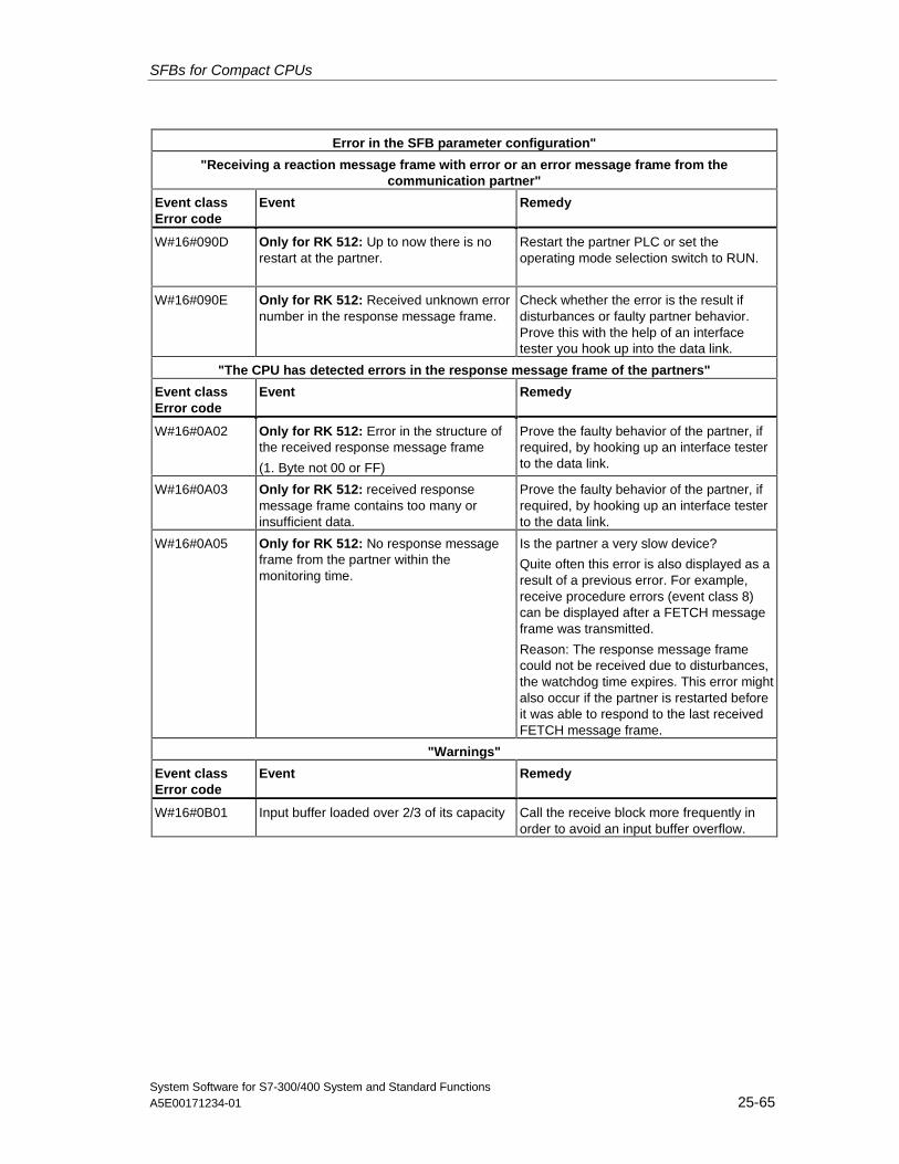
SFBs for Compact CPUs
System Software for S7-300/400 System and Standard FunctionsA5E00171234-01 25-65
Error in the SFB parameter configuration"
"Receiving a reaction message frame with error or an error message frame from thecommunication partner"
Event classError code
Event Remedy
W#16#090D Only for RK 512: Up to now there is norestart at the partner.
Restart the partner PLC or set theoperating mode selection switch to RUN.
W#16#090E Only for RK 512: Received unknown errornumber in the response message frame.
Check whether the error is the result ifdisturbances or faulty partner behavior.Prove this with the help of an interfacetester you hook up into the data link.
"The CPU has detected errors in the response message frame of the partners"
Event classError code
Event Remedy
W#16#0A02 Only for RK 512: Error in the structure ofthe received response message frame
(1. Byte not 00 or FF)
Prove the faulty behavior of the partner, ifrequired, by hooking up an interface testerto the data link.
W#16#0A03 Only for RK 512: received responsemessage frame contains too many orinsufficient data.
Prove the faulty behavior of the partner, ifrequired, by hooking up an interface testerto the data link.
W#16#0A05 Only for RK 512: No response messageframe from the partner within themonitoring time.
Is the partner a very slow device?
Quite often this error is also displayed as aresult of a previous error. For example,receive procedure errors (event class 8)can be displayed after a FETCH messageframe was transmitted.
Reason: The response message framecould not be received due to disturbances,the watchdog time expires. This error mightalso occur if the partner is restarted beforeit was able to respond to the last receivedFETCH message frame.
"Warnings"
Event classError code
Event Remedy
W#16#0B01 Input buffer loaded over 2/3 of its capacity Call the receive block more frequently inorder to avoid an input buffer overflow.

SFBs for Compact CPUs
System Software for S7-300/400 System and Standard Functions25-66 A5E00171234-01
System Software for S7-300/400 System and Standard FunctionsA5E00171234-01 26-1
26 SFCs for H CPUs
26.1 Controlling Operation in H Systems with SFC 90"H_CTRL"
Description
With SFC 90 "H_CTRL," you can influence H systems as follows:
• You can prevent the standby link-up in the master CPU. This is then disableduntil you cancel the setting with SFC 90 "H_CTRL."
Any request from the standby CPU to link-up with the master is stored.
• You can disable updating on the master CPU. This is then disabled until youcancel the setting with SFC 90 "H_CTRL."
Any request from the standby CPU to update is stored.
! Caution
If you have disabled update but not connect, the hardware system still candetermine the connection status as before. Please note that when the master CPUis connecting, it does not process any remove/insert interrupts, stationfailure/returned interrupts or rack failure/returned interrupts.
• You can remove a test component from the cyclical self-test, add it again orstart immediately.Note:If you use a CPU 414-4H or 417-4H in a redundant system, please observe thefollowing: If you disable the component for more than 24 hours, the CPU goesinto STOP mode. For redundant systems, the applicable regulation states thatcertain tests must be completed within 24 hours.
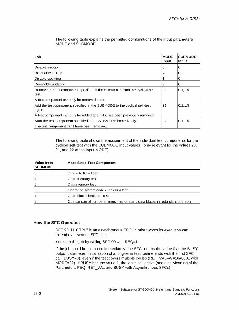
SFCs for H CPUs
System Software for S7-300/400 System and Standard Functions26-2 A5E00171234-01
The following table explains the permitted combinations of the input parametersMODE and SUBMODE.
Job MODEInput
SUBMODEInput
Disable link-up 3 0
Re-enable link-up 4 0
Disable updating 1 0
Re-enable updating 2 0
Remove the test component specified in the SUBMODE from the cyclical self-test.
A test component can only be removed once.
20 0.1,...5
Add the test component specified in the SUBMODE to the cyclical self-testagain.
A test component can only be added again if it has been previously removed.
21 0.1,...5
Start the test component specified in the SUBMODE immediately.
The test component can't have been removed.
22 0.1,...5
The following table shows the assignment of the individual test components for thecyclical self-test with the SUBMODE input values. (only relevant for the values 20,21, and 22 of the input MODE)
Value fromSUBMODE
Associated Test Component
0 SP7 – ASIC – Test
1 Code memory test
2 Data memory test
3 Operating system code checksum test
4 Code block checksum test
5 Comparison of numbers, times, markers and data blocks in redundant operation.
How the SFC Operates
SFC 90 "H_CTRL" is an asynchronous SFC, in other words its execution canextend over several SFC calls.
You start the job by calling SFC 90 with REQ=1.
If the job could be executed immediately, the SFC returns the value 0 at the BUSYoutput parameter. Initialization of a long-term test routine ends with the first SFCcall (BUSY=0), even if the test covers multiple cycles (RET_VAL=W#16#0001 withMODE=22). If BUSY has the value 1, the job is still active (see also Meaning of theParameters REQ, RET_VAL and BUSY with Asynchronous SFCs).
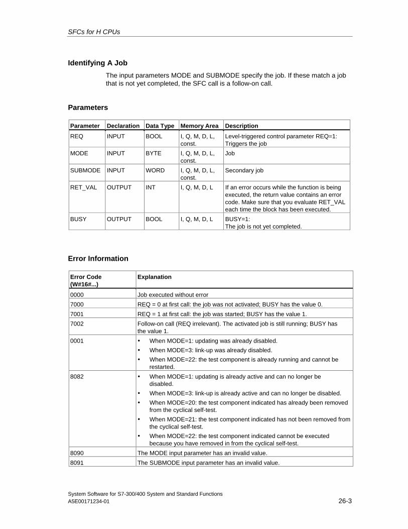
SFCs for H CPUs
System Software for S7-300/400 System and Standard FunctionsA5E00171234-01 26-3
Identifying A Job
The input parameters MODE and SUBMODE specify the job. If these match a jobthat is not yet completed, the SFC call is a follow-on call.
Parameters
Parameter Declaration Data Type Memory Area Description
REQ INPUT BOOL I, Q, M, D, L,const.
Level-triggered control parameter REQ=1:Triggers the job
MODE INPUT BYTE I, Q, M, D, L,const.
Job
SUBMODE INPUT WORD I, Q, M, D, L,const.
Secondary job
RET_VAL OUTPUT INT I, Q, M, D, L If an error occurs while the function is beingexecuted, the return value contains an errorcode. Make sure that you evaluate RET_VALeach time the block has been executed.
BUSY OUTPUT BOOL I, Q, M, D, L BUSY=1:The job is not yet completed.
Error Information
Error Code(W#16#...)
Explanation
0000 Job executed without error
7000 REQ = 0 at first call: the job was not activated; BUSY has the value 0.
7001 REQ = 1 at first call: the job was started; BUSY has the value 1.
7002 Follow-on call (REQ irrelevant). The activated job is still running; BUSY hasthe value 1.
0001 • When MODE=1: updating was already disabled.
• When MODE=3: link-up was already disabled.
• When MODE=22: the test component is already running and cannot berestarted.
8082 • When MODE=1: updating is already active and can no longer bedisabled.
• When MODE=3: link-up is already active and can no longer be disabled.
• When MODE=20: the test component indicated has already been removedfrom the cyclical self-test.
• When MODE=21: the test component indicated has not been removed fromthe cyclical self-test.
• When MODE=22: the test component indicated cannot be executedbecause you have removed in from the cyclical self-test.
8090 The MODE input parameter has an invalid value.
8091 The SUBMODE input parameter has an invalid value.
SFCs for H CPUs
System Software for S7-300/400 System and Standard Functions26-4 A5E00171234-01
Example of Using SFC 90
With SFC 90 "H_CTRL," you can make sure that no link-up and no updating isstarted at times when the maximum resources of the CPU are required.
You can achieve this by including the following program sections on the masterCPU prior to the period of increased process activity:
• Call SFC 90 with MODE = 3 and SUBMODE =0 (disable link-up)
• Call SFC 90 with MODE = 1 and SUBMODE = 0 (disable updating)
At the end of the period of increased activity, include the following programsections on the master CPU:
• Call SFC 90 with MODE = 4 and SUBMODE = 0 (re-enable link-up)
• Call SFC 90 with MODE = 2 and SUBMODE = 0 (re-enable updating).
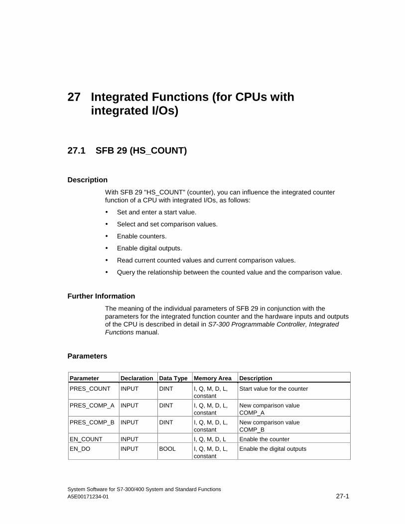
System Software for S7-300/400 System and Standard FunctionsA5E00171234-01 27-1
27 Integrated Functions (for CPUs withintegrated I/Os)
27.1 SFB 29 (HS_COUNT)
Description
With SFB 29 "HS_COUNT" (counter), you can influence the integrated counterfunction of a CPU with integrated I/Os, as follows:
• Set and enter a start value.
• Select and set comparison values.
• Enable counters.
• Enable digital outputs.
• Read current counted values and current comparison values.
• Query the relationship between the counted value and the comparison value.
Further Information
The meaning of the individual parameters of SFB 29 in conjunction with theparameters for the integrated function counter and the hardware inputs and outputsof the CPU is described in detail in S7-300 Programmable Controller, IntegratedFunctions manual.
Parameters
Parameter Declaration Data Type Memory Area Description
PRES_COUNT INPUT DINT I, Q, M, D, L,constant
Start value for the counter
PRES_COMP_A INPUT DINT I, Q, M, D, L,constant
New comparison valueCOMP_A
PRES_COMP_B INPUT DINT I, Q, M, D, L,constant
New comparison valueCOMP_B
EN_COUNT INPUT I, Q, M, D, L Enable the counter
EN_DO INPUT BOOL I, Q, M, D, L,constant
Enable the digital outputs
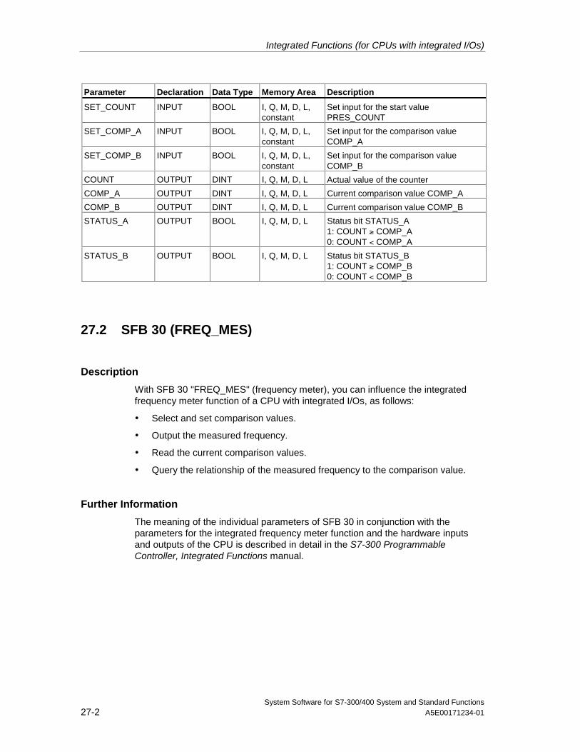
Integrated Functions (for CPUs with integrated I/Os)
System Software for S7-300/400 System and Standard Functions27-2 A5E00171234-01
Parameter Declaration Data Type Memory Area Description
SET_COUNT INPUT BOOL I, Q, M, D, L,constant
Set input for the start valuePRES_COUNT
SET_COMP_A INPUT BOOL I, Q, M, D, L,constant
Set input for the comparison valueCOMP_A
SET_COMP_B INPUT BOOL I, Q, M, D, L,constant
Set input for the comparison valueCOMP_B
COUNT OUTPUT DINT I, Q, M, D, L Actual value of the counter
COMP_A OUTPUT DINT I, Q, M, D, L Current comparison value COMP_A
COMP_B OUTPUT DINT I, Q, M, D, L Current comparison value COMP_B
STATUS_A OUTPUT BOOL I, Q, M, D, L Status bit STATUS_A1: COUNT ≥ COMP_A0: COUNT < COMP_A
STATUS_B OUTPUT BOOL I, Q, M, D, L Status bit STATUS_B1: COUNT ≥ COMP_B0: COUNT < COMP_B
27.2 SFB 30 (FREQ_MES)
Description
With SFB 30 "FREQ_MES" (frequency meter), you can influence the integratedfrequency meter function of a CPU with integrated I/Os, as follows:
• Select and set comparison values.
• Output the measured frequency.
• Read the current comparison values.
• Query the relationship of the measured frequency to the comparison value.
Further Information
The meaning of the individual parameters of SFB 30 in conjunction with theparameters for the integrated frequency meter function and the hardware inputsand outputs of the CPU is described in detail in the S7-300 ProgrammableController, Integrated Functions manual.
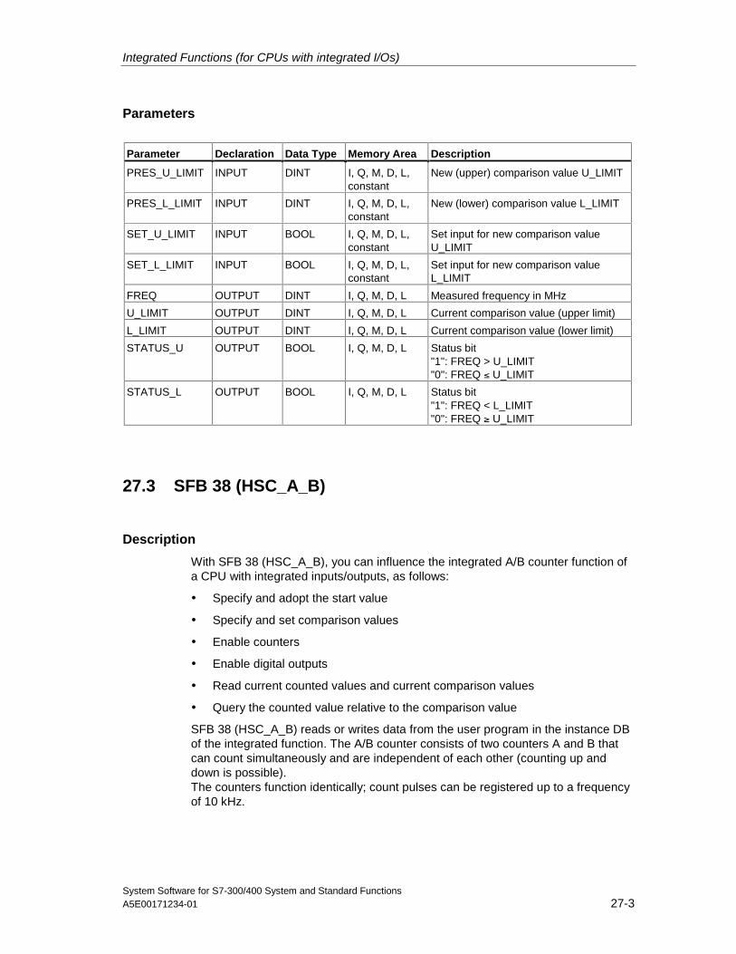
Integrated Functions (for CPUs with integrated I/Os)
System Software for S7-300/400 System and Standard FunctionsA5E00171234-01 27-3
Parameters
Parameter Declaration Data Type Memory Area Description
PRES_U_LIMIT INPUT DINT I, Q, M, D, L,constant
New (upper) comparison value U_LIMIT
PRES_L_LIMIT INPUT DINT I, Q, M, D, L,constant
New (lower) comparison value L_LIMIT
SET_U_LIMIT INPUT BOOL I, Q, M, D, L,constant
Set input for new comparison valueU_LIMIT
SET_L_LIMIT INPUT BOOL I, Q, M, D, L,constant
Set input for new comparison valueL_LIMIT
FREQ OUTPUT DINT I, Q, M, D, L Measured frequency in MHz
U_LIMIT OUTPUT DINT I, Q, M, D, L Current comparison value (upper limit)
L_LIMIT OUTPUT DINT I, Q, M, D, L Current comparison value (lower limit)
STATUS_U OUTPUT BOOL I, Q, M, D, L Status bit"1": FREQ > U_LIMIT"0": FREQ ≤ U_LIMIT
STATUS_L OUTPUT BOOL I, Q, M, D, L Status bit"1": FREQ < L_LIMIT"0": FREQ ≥ U_LIMIT
27.3 SFB 38 (HSC_A_B)
Description
With SFB 38 (HSC_A_B), you can influence the integrated A/B counter function ofa CPU with integrated inputs/outputs, as follows:
• Specify and adopt the start value
• Specify and set comparison values
• Enable counters
• Enable digital outputs
• Read current counted values and current comparison values
• Query the counted value relative to the comparison value
SFB 38 (HSC_A_B) reads or writes data from the user program in the instance DBof the integrated function. The A/B counter consists of two counters A and B thatcan count simultaneously and are independent of each other (counting up anddown is possible).The counters function identically; count pulses can be registered up to a frequencyof 10 kHz.
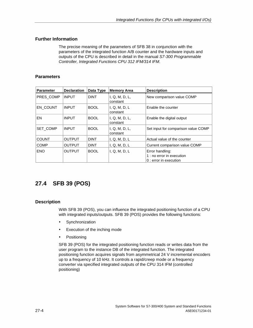
Integrated Functions (for CPUs with integrated I/Os)
System Software for S7-300/400 System and Standard Functions27-4 A5E00171234-01
Further Information
The precise meaning of the parameters of SFB 38 in conjunction with theparameters of the integrated function A/B counter and the hardware inputs andoutputs of the CPU is described in detail in the manual S7-300 ProgrammableController, Integrated Functions CPU 312 IFM/314 IFM.
Parameters
Parameter Declaration Data Type Memory Area Description
PRES_COMP INPUT DINT I, Q, M, D, L,constant
New comparison value COMP
EN_COUNT INPUT BOOL I, Q, M, D, Lconstant
Enable the counter
EN INPUT BOOL I, Q, M, D, L,constant
Enable the digital output
SET_COMP INPUT BOOL I, Q, M, D, L,constant
Set input for comparison value COMP
COUNT OUTPUT DINT I, Q, M, D, L Actual value of the counter
COMP OUTPUT DINT I, Q, M, D, L Current comparison value COMP
ENO OUTPUT BOOL I, Q, M, D, L Error handling:1 : no error in execution0 : error in execution
27.4 SFB 39 (POS)
Description
With SFB 39 (POS), you can influence the integrated positioning function of a CPUwith integrated inputs/outputs. SFB 39 (POS) provides the following functions:
• Synchronization
• Execution of the inching mode
• Positioning
SFB 39 (POS) for the integrated positioning function reads or writes data from theuser program to the instance DB of the integrated function. The integratedpositioning function acquires signals from asymmetrical 24 V incremental encodersup to a frequency of 10 kHz. It controls a rapid/creep mode or a frequencyconverter via specified integrated outputs of the CPU 314 IFM (controlledpositioning)
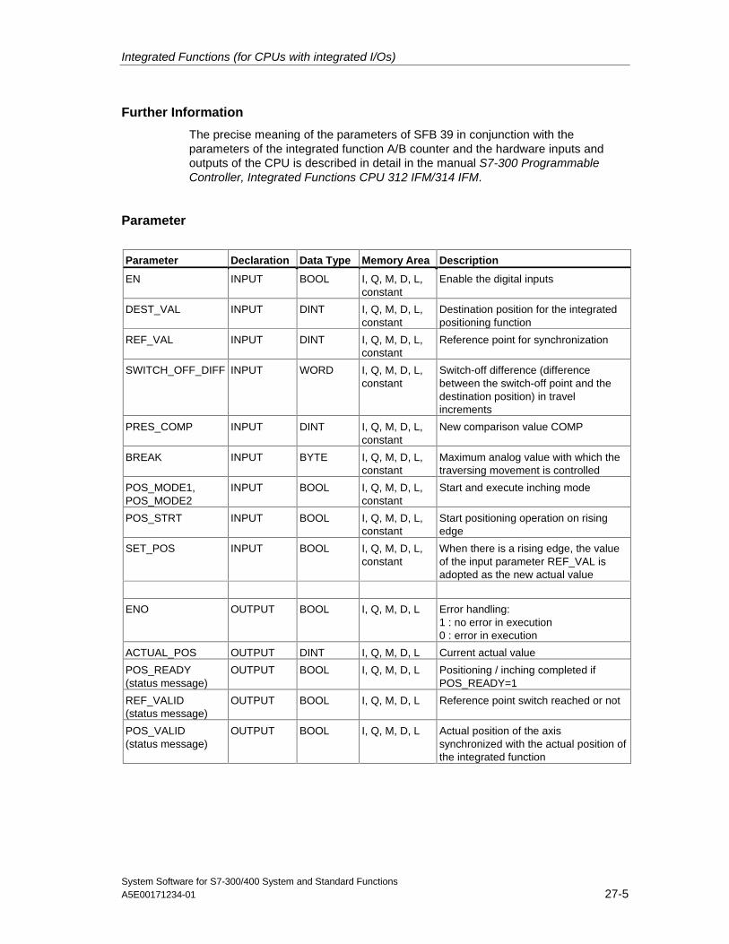
Integrated Functions (for CPUs with integrated I/Os)
System Software for S7-300/400 System and Standard FunctionsA5E00171234-01 27-5
Further Information
The precise meaning of the parameters of SFB 39 in conjunction with theparameters of the integrated function A/B counter and the hardware inputs andoutputs of the CPU is described in detail in the manual S7-300 ProgrammableController, Integrated Functions CPU 312 IFM/314 IFM.
Parameter
Parameter Declaration Data Type Memory Area Description
EN INPUT BOOL I, Q, M, D, L,constant
Enable the digital inputs
DEST_VAL INPUT DINT I, Q, M, D, L,constant
Destination position for the integratedpositioning function
REF_VAL INPUT DINT I, Q, M, D, L,constant
Reference point for synchronization
SWITCH_OFF_DIFF INPUT WORD I, Q, M, D, L,constant
Switch-off difference (differencebetween the switch-off point and thedestination position) in travelincrements
PRES_COMP INPUT DINT I, Q, M, D, L,constant
New comparison value COMP
BREAK INPUT BYTE I, Q, M, D, L,constant
Maximum analog value with which thetraversing movement is controlled
POS_MODE1,POS_MODE2
INPUT BOOL I, Q, M, D, L,constant
Start and execute inching mode
POS_STRT INPUT BOOL I, Q, M, D, L,constant
Start positioning operation on risingedge
SET_POS INPUT BOOL I, Q, M, D, L,constant
When there is a rising edge, the valueof the input parameter REF_VAL isadopted as the new actual value
ENO OUTPUT BOOL I, Q, M, D, L Error handling:1 : no error in execution0 : error in execution
ACTUAL_POS OUTPUT DINT I, Q, M, D, L Current actual value
POS_READY(status message)
OUTPUT BOOL I, Q, M, D, L Positioning / inching completed ifPOS_READY=1
REF_VALID(status message)
OUTPUT BOOL I, Q, M, D, L Reference point switch reached or not
POS_VALID(status message)
OUTPUT BOOL I, Q, M, D, L Actual position of the axissynchronized with the actual position ofthe integrated function
Integrated Functions (for CPUs with integrated I/Os)
System Software for S7-300/400 System and Standard Functions27-6 A5E00171234-01
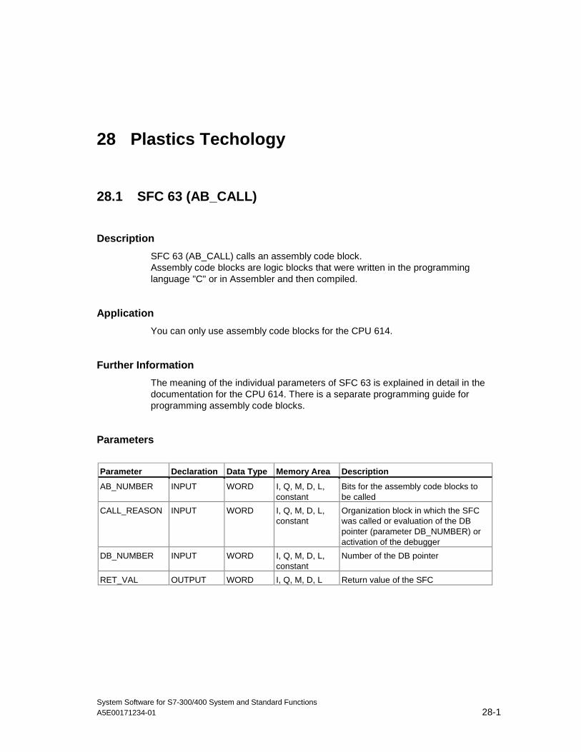
System Software for S7-300/400 System and Standard FunctionsA5E00171234-01 28-1
28 Plastics Techology
28.1 SFC 63 (AB_CALL)
Description
SFC 63 (AB_CALL) calls an assembly code block.Assembly code blocks are logic blocks that were written in the programminglanguage "C" or in Assembler and then compiled.
Application
You can only use assembly code blocks for the CPU 614.
Further Information
The meaning of the individual parameters of SFC 63 is explained in detail in thedocumentation for the CPU 614. There is a separate programming guide forprogramming assembly code blocks.
Parameters
Parameter Declaration Data Type Memory Area Description
AB_NUMBER INPUT WORD I, Q, M, D, L,constant
Bits for the assembly code blocks tobe called
CALL_REASON INPUT WORD I, Q, M, D, L,constant
Organization block in which the SFCwas called or evaluation of the DBpointer (parameter DB_NUMBER) oractivation of the debugger
DB_NUMBER INPUT WORD I, Q, M, D, L,constant
Number of the DB pointer
RET_VAL OUTPUT WORD I, Q, M, D, L Return value of the SFC

Plastics Techology
System Software for S7-300/400 System and Standard Functions28-2 A5E00171234-01
System Software for S7-300/400 System and Standard FunctionsA5E00171234-01 29-1
29 Diagnostic Data
29.1 Overview of the Structure of Diagnostic Data
Data Record 0 and 1 of the System Data
The diagnostic data of a module are located in data records 0 and 1 of the systemdata area (see Writing and Reading Data Records).
• Data record 0 contains 4 bytes of diagnostic data that describe the currentstatus of a signal module.
• Data record 1 contains
- The 4 bytes of diagnostic data, also located in data record 0 and
- The diagnostic data specific to the module.
Structure and Contents of the Diagnostic Data
This section describes the structure and contents of the individual bytes of thediagnostic data.
Whenever an error occurs, the corresponding bit is set to "1."
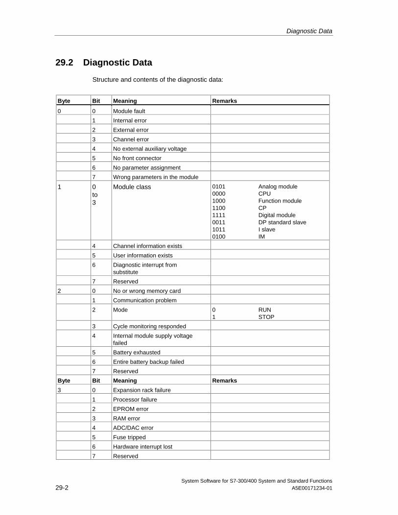
Diagnostic Data
System Software for S7-300/400 System and Standard Functions29-2 A5E00171234-01
29.2 Diagnostic Data
Structure and contents of the diagnostic data:
Byte Bit Meaning Remarks
0 0 Module fault
1 Internal error
2 External error
3 Channel error
4 No external auxiliary voltage
5 No front connector
6 No parameter assignment
7 Wrong parameters in the module
1 0to3
Module class 0101 Analog module0000 CPU1000 Function module1100 CP1111 Digital module0011 DP standard slave1011 I slave0100 IM
4 Channel information exists
5 User information exists
6 Diagnostic interrupt fromsubstitute
7 Reserved
2 0 No or wrong memory card
1 Communication problem
2 Mode 0 RUN1 STOP
3 Cycle monitoring responded
4 Internal module supply voltagefailed
5 Battery exhausted
6 Entire battery backup failed
7 Reserved
Byte Bit Meaning Remarks
3 0 Expansion rack failure
1 Processor failure
2 EPROM error
3 RAM error
4 ADC/DAC error
5 Fuse tripped
6 Hardware interrupt lost
7 Reserved
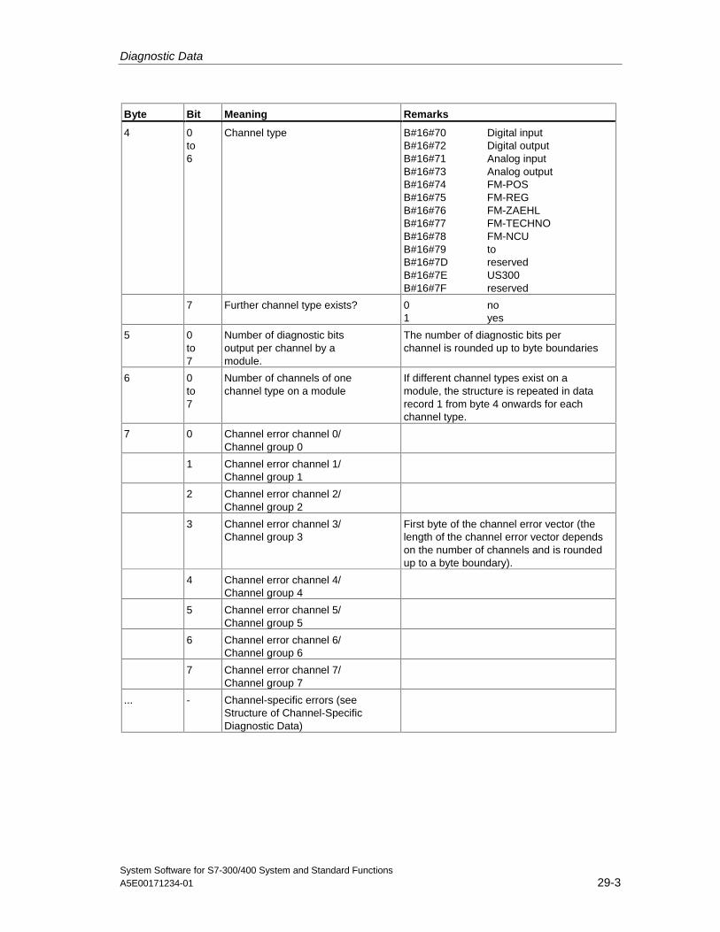
Diagnostic Data
System Software for S7-300/400 System and Standard FunctionsA5E00171234-01 29-3
Byte Bit Meaning Remarks
4 0to6
Channel type B#16#70 Digital inputB#16#72 Digital outputB#16#71 Analog inputB#16#73 Analog outputB#16#74 FM-POSB#16#75 FM-REGB#16#76 FM-ZAEHLB#16#77 FM-TECHNOB#16#78 FM-NCUB#16#79 toB#16#7D reservedB#16#7E US300B#16#7F reserved
7 Further channel type exists? 0 no1 yes
5 0to7
Number of diagnostic bitsoutput per channel by amodule.
The number of diagnostic bits perchannel is rounded up to byte boundaries
6 0to7
Number of channels of onechannel type on a module
If different channel types exist on amodule, the structure is repeated in datarecord 1 from byte 4 onwards for eachchannel type.
7 0 Channel error channel 0/Channel group 0
1 Channel error channel 1/Channel group 1
2 Channel error channel 2/Channel group 2
3 Channel error channel 3/Channel group 3
First byte of the channel error vector (thelength of the channel error vector dependson the number of channels and is roundedup to a byte boundary).
4 Channel error channel 4/Channel group 4
5 Channel error channel 5/Channel group 5
6 Channel error channel 6/Channel group 6
7 Channel error channel 7/Channel group 7
... - Channel-specific errors (seeStructure of Channel-SpecificDiagnostic Data)
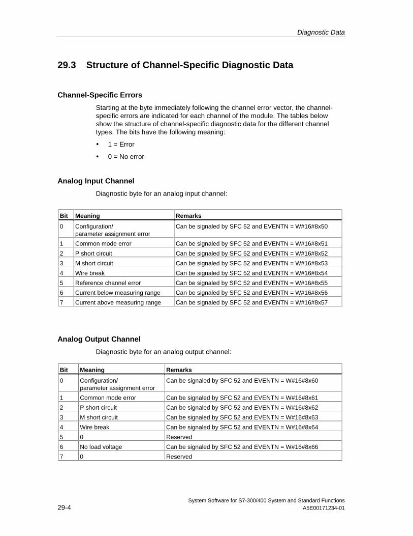
Diagnostic Data
System Software for S7-300/400 System and Standard Functions29-4 A5E00171234-01
29.3 Structure of Channel-Specific Diagnostic Data
Channel-Specific Errors
Starting at the byte immediately following the channel error vector, the channel-specific errors are indicated for each channel of the module. The tables belowshow the structure of channel-specific diagnostic data for the different channeltypes. The bits have the following meaning:
• 1 = Error
• 0 = No error
Analog Input Channel
Diagnostic byte for an analog input channel:
Bit Meaning Remarks
0 Configuration/parameter assignment error
Can be signaled by SFC 52 and EVENTN = W#16#8x50
1 Common mode error Can be signaled by SFC 52 and EVENTN = W#16#8x51
2 P short circuit Can be signaled by SFC 52 and EVENTN = W#16#8x52
3 M short circuit Can be signaled by SFC 52 and EVENTN = W#16#8x53
4 Wire break Can be signaled by SFC 52 and EVENTN = W#16#8x54
5 Reference channel error Can be signaled by SFC 52 and EVENTN = W#16#8x55
6 Current below measuring range Can be signaled by SFC 52 and EVENTN = W#16#8x56
7 Current above measuring range Can be signaled by SFC 52 and EVENTN = W#16#8x57
Analog Output Channel
Diagnostic byte for an analog output channel:
Bit Meaning Remarks
0 Configuration/parameter assignment error
Can be signaled by SFC 52 and EVENTN = W#16#8x60
1 Common mode error Can be signaled by SFC 52 and EVENTN = W#16#8x61
2 P short circuit Can be signaled by SFC 52 and EVENTN = W#16#8x62
3 M short circuit Can be signaled by SFC 52 and EVENTN = W#16#8x63
4 Wire break Can be signaled by SFC 52 and EVENTN = W#16#8x64
5 0 Reserved
6 No load voltage Can be signaled by SFC 52 and EVENTN = W#16#8x66
7 0 Reserved
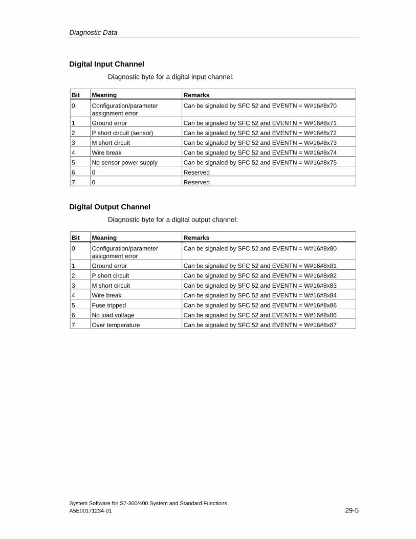
Diagnostic Data
System Software for S7-300/400 System and Standard FunctionsA5E00171234-01 29-5
Digital Input Channel
Diagnostic byte for a digital input channel:
Bit Meaning Remarks
0 Configuration/parameterassignment error
Can be signaled by SFC 52 and EVENTN = W#16#8x70
1 Ground error Can be signaled by SFC 52 and EVENTN = W#16#8x71
2 P short circuit (sensor) Can be signaled by SFC 52 and EVENTN = W#16#8x72
3 M short circuit Can be signaled by SFC 52 and EVENTN = W#16#8x73
4 Wire break Can be signaled by SFC 52 and EVENTN = W#16#8x74
5 No sensor power supply Can be signaled by SFC 52 and EVENTN = W#16#8x75
6 0 Reserved
7 0 Reserved
Digital Output Channel
Diagnostic byte for a digital output channel:
Bit Meaning Remarks
0 Configuration/parameterassignment error
Can be signaled by SFC 52 and EVENTN = W#16#8x80
1 Ground error Can be signaled by SFC 52 and EVENTN = W#16#8x81
2 P short circuit Can be signaled by SFC 52 and EVENTN = W#16#8x82
3 M short circuit Can be signaled by SFC 52 and EVENTN = W#16#8x83
4 Wire break Can be signaled by SFC 52 and EVENTN = W#16#8x84
5 Fuse tripped Can be signaled by SFC 52 and EVENTN = W#16#8x86
6 No load voltage Can be signaled by SFC 52 and EVENTN = W#16#8x86
7 Over temperature Can be signaled by SFC 52 and EVENTN = W#16#8x87

Diagnostic Data
System Software for S7-300/400 System and Standard Functions29-6 A5E00171234-01
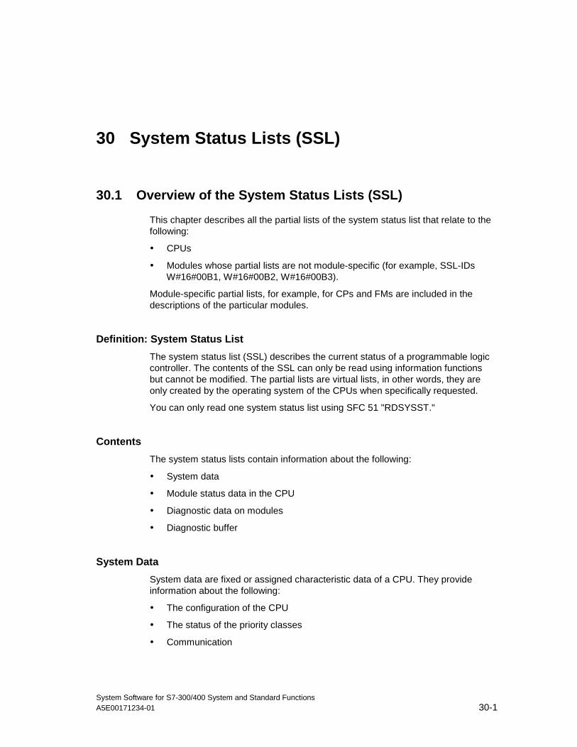
System Software for S7-300/400 System and Standard FunctionsA5E00171234-01 30-1
30 System Status Lists (SSL)
30.1 Overview of the System Status Lists (SSL)
This chapter describes all the partial lists of the system status list that relate to thefollowing:
• CPUs
• Modules whose partial lists are not module-specific (for example, SSL-IDsW#16#00B1, W#16#00B2, W#16#00B3).
Module-specific partial lists, for example, for CPs and FMs are included in thedescriptions of the particular modules.
Definition: System Status List
The system status list (SSL) describes the current status of a programmable logiccontroller. The contents of the SSL can only be read using information functionsbut cannot be modified. The partial lists are virtual lists, in other words, they areonly created by the operating system of the CPUs when specifically requested.
You can only read one system status list using SFC 51 "RDSYSST."
Contents
The system status lists contain information about the following:
• System data
• Module status data in the CPU
• Diagnostic data on modules
• Diagnostic buffer
System Data
System data are fixed or assigned characteristic data of a CPU. They provideinformation about the following:
• The configuration of the CPU
• The status of the priority classes
• Communication
System Status Lists (SSL)
System Software for S7-300/400 System and Standard Functions30-2 A5E00171234-01
Module Status Data
Module status data describe the current status of the components monitored bysystem diagnostic functions.
Diagnostic Data on Modules
The modules with diagnostic capabilities assigned to a CPU have diagnostic datathat are stored directly on the module.
Diagnostic Buffer
The diagnostic buffer contains diagnostic entries in the order in which they occur.
System Status Lists (SSL)
System Software for S7-300/400 System and Standard FunctionsA5E00171234-01 30-3
30.2 Structure of a Partial SSL List
Basics
You can read partial lists and partial list extracts using SFC 51 "RDSYSST." Youspecify what you want to read using the parameters SSL_ID and INDEX.
Structure
A partial list consists of the following:
• A header and
• The data records.
Header
The header of a partial list consists of the following:
• SSL-ID
• Index
• Length of a data record of the partial list in bytes
• Number of data records contained in the partial list.
Index
With certain partial lists or partial list extracts an object type ID or an object numbermust be specified. The index is used for this purpose. If it is not required for theinformation, its contents are irrelevant.
Data Records
A data record in a partial list has a specific length. This depends on the informationin the partial list. How the data words in a data record are used also depends onthe particular partial list.
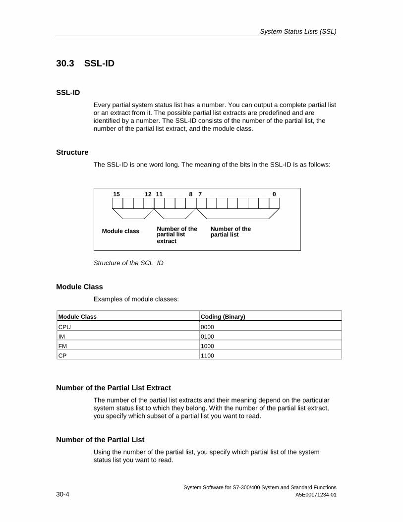
System Status Lists (SSL)
System Software for S7-300/400 System and Standard Functions30-4 A5E00171234-01
30.3 SSL-ID
SSL-ID
Every partial system status list has a number. You can output a complete partial listor an extract from it. The possible partial list extracts are predefined and areidentified by a number. The SSL-ID consists of the number of the partial list, thenumber of the partial list extract, and the module class.
Structure
The SSL-ID is one word long. The meaning of the bits in the SSL-ID is as follows:
1215 811 7 0
Module class Number of thepartial listextract
Number of thepartial list
Structure of the SCL_ID
Module Class
Examples of module classes:
Module Class Coding (Binary)
CPU 0000
IM 0100
FM 1000
CP 1100
Number of the Partial List Extract
The number of the partial list extracts and their meaning depend on the particularsystem status list to which they belong. With the number of the partial list extract,you specify which subset of a partial list you want to read.
Number of the Partial List
Using the number of the partial list, you specify which partial list of the systemstatus list you want to read.
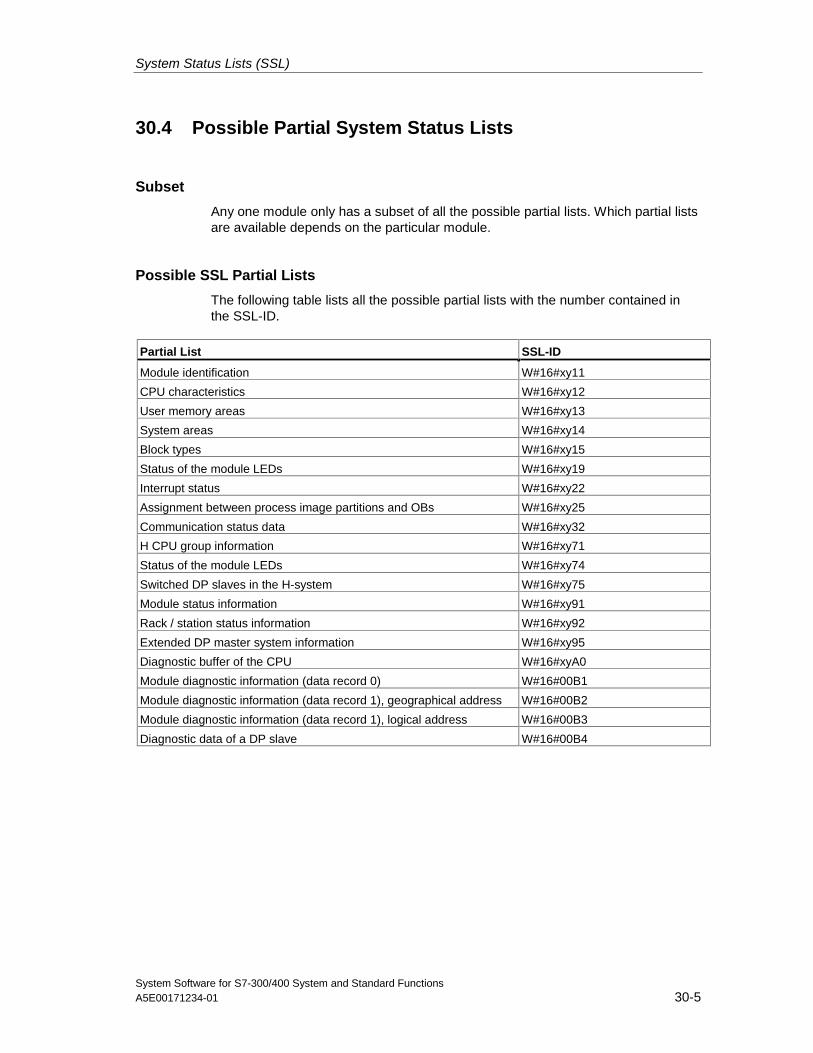
System Status Lists (SSL)
System Software for S7-300/400 System and Standard FunctionsA5E00171234-01 30-5
30.4 Possible Partial System Status Lists
Subset
Any one module only has a subset of all the possible partial lists. Which partial listsare available depends on the particular module.
Possible SSL Partial Lists
The following table lists all the possible partial lists with the number contained inthe SSL-ID.
Partial List SSL-ID
Module identification W#16#xy11
CPU characteristics W#16#xy12
User memory areas W#16#xy13
System areas W#16#xy14
Block types W#16#xy15
Status of the module LEDs W#16#xy19
Interrupt status W#16#xy22
Assignment between process image partitions and OBs W#16#xy25
Communication status data W#16#xy32
H CPU group information W#16#xy71
Status of the module LEDs W#16#xy74
Switched DP slaves in the H-system W#16#xy75
Module status information W#16#xy91
Rack / station status information W#16#xy92
Extended DP master system information W#16#xy95
Diagnostic buffer of the CPU W#16#xyA0
Module diagnostic information (data record 0) W#16#00B1
Module diagnostic information (data record 1), geographical address W#16#00B2
Module diagnostic information (data record 1), logical address W#16#00B3
Diagnostic data of a DP slave W#16#00B4
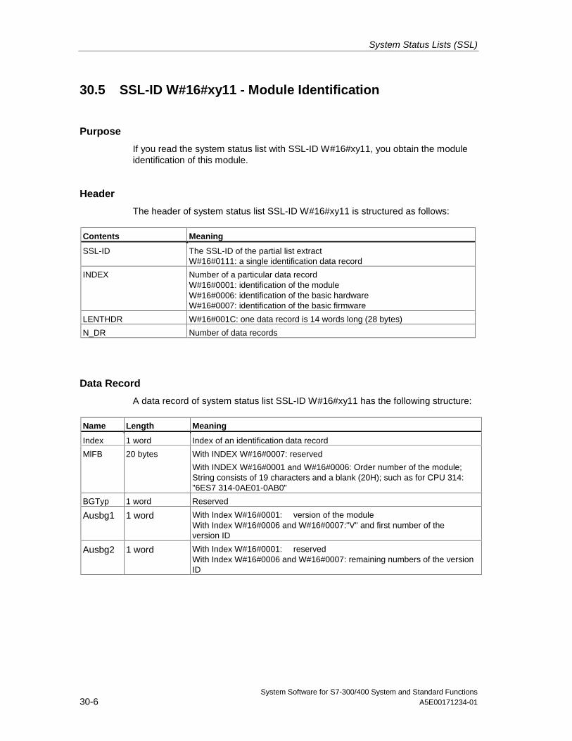
System Status Lists (SSL)
System Software for S7-300/400 System and Standard Functions30-6 A5E00171234-01
30.5 SSL-ID W#16#xy11 - Module Identification
Purpose
If you read the system status list with SSL-ID W#16#xy11, you obtain the moduleidentification of this module.
Header
The header of system status list SSL-ID W#16#xy11 is structured as follows:
Contents Meaning
SSL-ID The SSL-ID of the partial list extractW#16#0111: a single identification data record
INDEX Number of a particular data recordW#16#0001: identification of the moduleW#16#0006: identification of the basic hardwareW#16#0007: identification of the basic firmware
LENTHDR W#16#001C: one data record is 14 words long (28 bytes)
N_DR Number of data records
Data Record
A data record of system status list SSL-ID W#16#xy11 has the following structure:
Name Length Meaning
Index 1 word Index of an identification data record
MlFB 20 bytes With INDEX W#16#0007: reserved
With INDEX W#16#0001 and W#16#0006: Order number of the module;String consists of 19 characters and a blank (20H); such as for CPU 314:"6ES7 314-0AE01-0AB0"
BGTyp 1 word Reserved
Ausbg1 1 word With Index W#16#0001: version of the moduleWith Index W#16#0006 and W#16#0007:"V" and first number of theversion ID
Ausbg2 1 word With Index W#16#0001: reservedWith Index W#16#0006 and W#16#0007: remaining numbers of the versionID
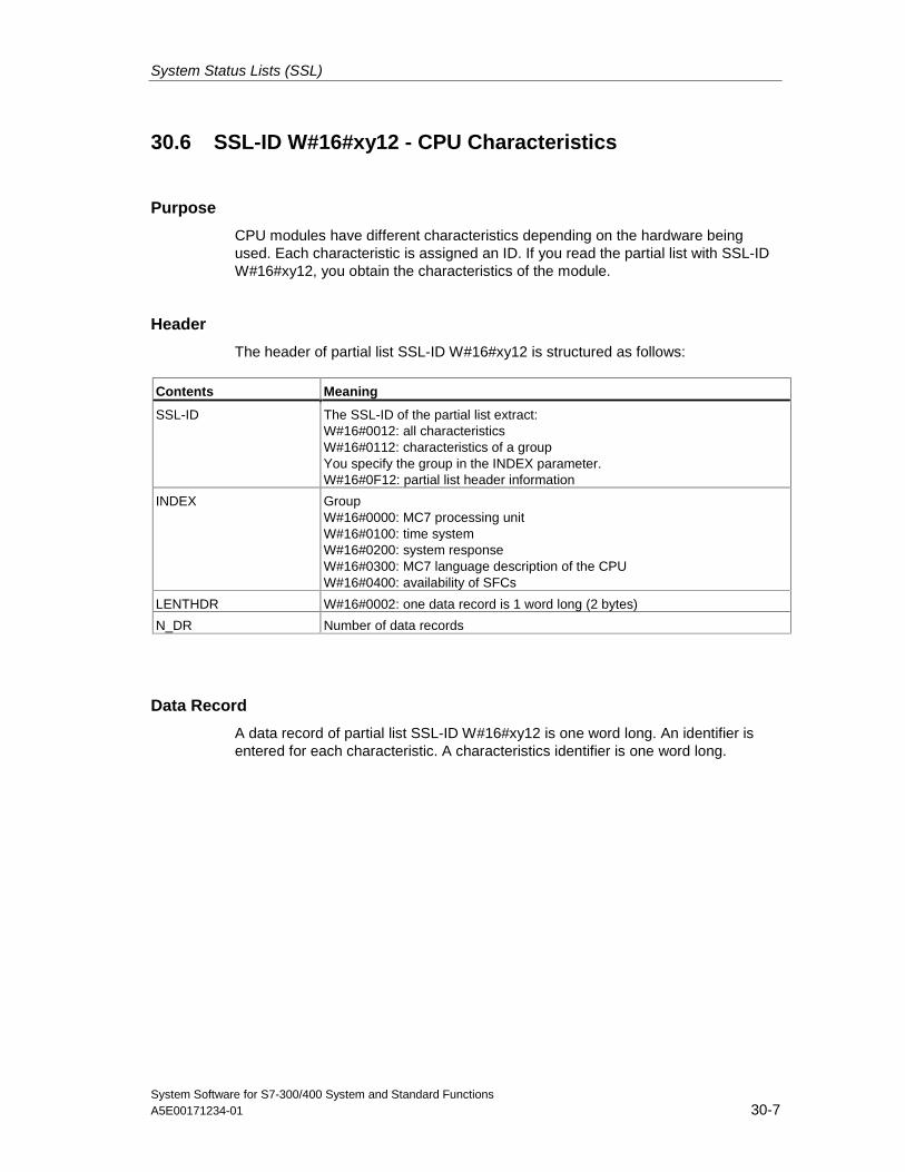
System Status Lists (SSL)
System Software for S7-300/400 System and Standard FunctionsA5E00171234-01 30-7
30.6 SSL-ID W#16#xy12 - CPU Characteristics
Purpose
CPU modules have different characteristics depending on the hardware beingused. Each characteristic is assigned an ID. If you read the partial list with SSL-IDW#16#xy12, you obtain the characteristics of the module.
Header
The header of partial list SSL-ID W#16#xy12 is structured as follows:
Contents Meaning
SSL-ID The SSL-ID of the partial list extract:W#16#0012: all characteristicsW#16#0112: characteristics of a groupYou specify the group in the INDEX parameter.W#16#0F12: partial list header information
INDEX GroupW#16#0000: MC7 processing unitW#16#0100: time systemW#16#0200: system responseW#16#0300: MC7 language description of the CPUW#16#0400: availability of SFCs
LENTHDR W#16#0002: one data record is 1 word long (2 bytes)
N_DR Number of data records
Data Record
A data record of partial list SSL-ID W#16#xy12 is one word long. An identifier isentered for each characteristic. A characteristics identifier is one word long.
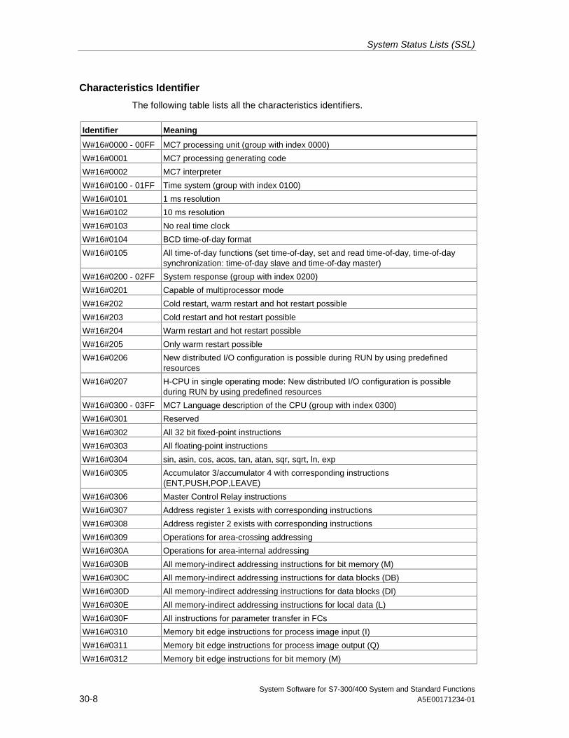
System Status Lists (SSL)
System Software for S7-300/400 System and Standard Functions30-8 A5E00171234-01
Characteristics Identifier
The following table lists all the characteristics identifiers.
Identifier Meaning
W#16#0000 - 00FF MC7 processing unit (group with index 0000)
W#16#0001 MC7 processing generating code
W#16#0002 MC7 interpreter
W#16#0100 - 01FF Time system (group with index 0100)
W#16#0101 1 ms resolution
W#16#0102 10 ms resolution
W#16#0103 No real time clock
W#16#0104 BCD time-of-day format
W#16#0105 All time-of-day functions (set time-of-day, set and read time-of-day, time-of-daysynchronization: time-of-day slave and time-of-day master)
W#16#0200 - 02FF System response (group with index 0200)
W#16#0201 Capable of multiprocessor mode
W#16#202 Cold restart, warm restart and hot restart possible
W#16#203 Cold restart and hot restart possible
W#16#204 Warm restart and hot restart possible
W#16#205 Only warm restart possible
W#16#0206 New distributed I/O configuration is possible during RUN by using predefinedresources
W#16#0207 H-CPU in single operating mode: New distributed I/O configuration is possibleduring RUN by using predefined resources
W#16#0300 - 03FF MC7 Language description of the CPU (group with index 0300)
W#16#0301 Reserved
W#16#0302 All 32 bit fixed-point instructions
W#16#0303 All floating-point instructions
W#16#0304 sin, asin, cos, acos, tan, atan, sqr, sqrt, ln, exp
W#16#0305 Accumulator 3/accumulator 4 with corresponding instructions(ENT,PUSH,POP,LEAVE)
W#16#0306 Master Control Relay instructions
W#16#0307 Address register 1 exists with corresponding instructions
W#16#0308 Address register 2 exists with corresponding instructions
W#16#0309 Operations for area-crossing addressing
W#16#030A Operations for area-internal addressing
W#16#030B All memory-indirect addressing instructions for bit memory (M)
W#16#030C All memory-indirect addressing instructions for data blocks (DB)
W#16#030D All memory-indirect addressing instructions for data blocks (DI)
W#16#030E All memory-indirect addressing instructions for local data (L)
W#16#030F All instructions for parameter transfer in FCs
W#16#0310 Memory bit edge instructions for process image input (I)
W#16#0311 Memory bit edge instructions for process image output (Q)
W#16#0312 Memory bit edge instructions for bit memory (M)
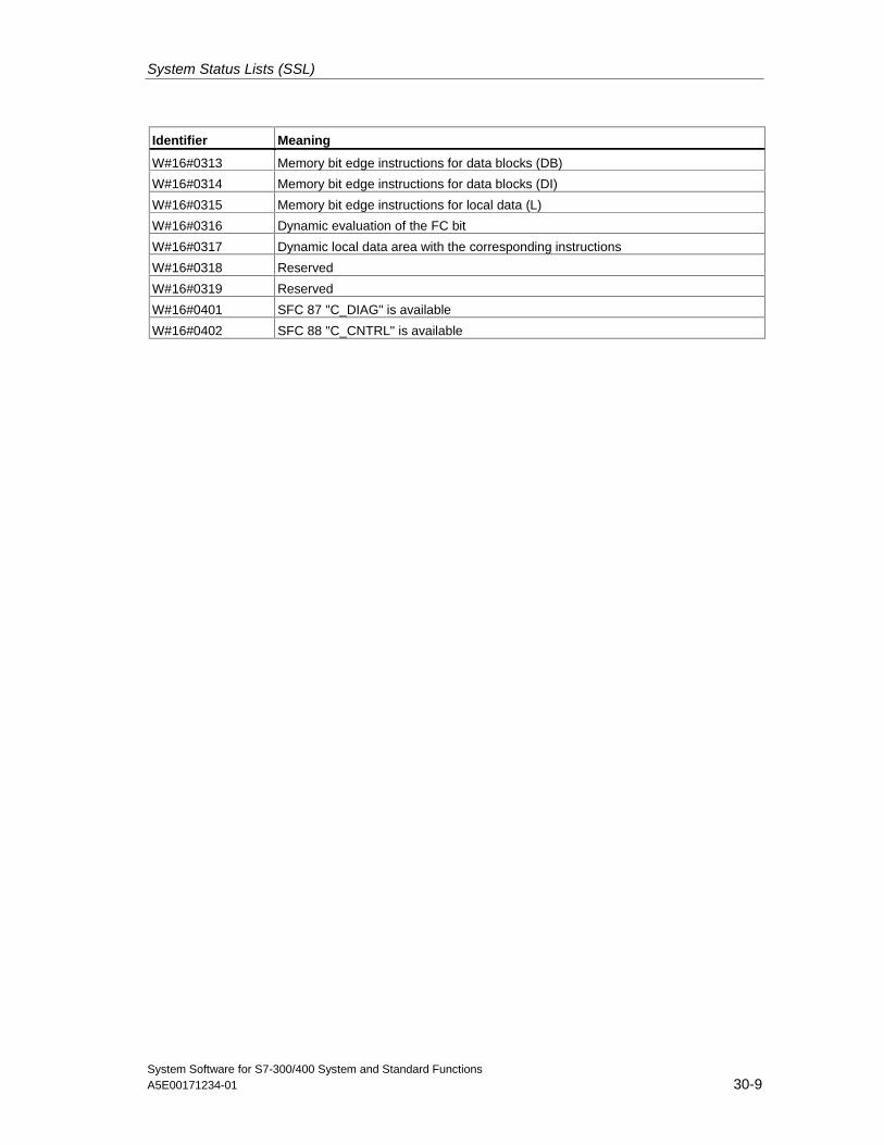
System Status Lists (SSL)
System Software for S7-300/400 System and Standard FunctionsA5E00171234-01 30-9
Identifier Meaning
W#16#0313 Memory bit edge instructions for data blocks (DB)
W#16#0314 Memory bit edge instructions for data blocks (DI)
W#16#0315 Memory bit edge instructions for local data (L)
W#16#0316 Dynamic evaluation of the FC bit
W#16#0317 Dynamic local data area with the corresponding instructions
W#16#0318 Reserved
W#16#0319 Reserved
W#16#0401 SFC 87 "C_DIAG" is available
W#16#0402 SFC 88 "C_CNTRL" is available
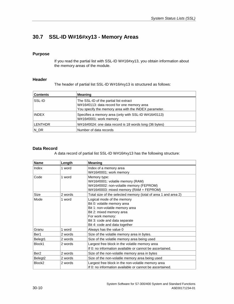
System Status Lists (SSL)
System Software for S7-300/400 System and Standard Functions30-10 A5E00171234-01
30.7 SSL-ID W#16#xy13 - Memory Areas
Purpose
If you read the partial list with SSL-ID W#16#xy13, you obtain information aboutthe memory areas of the module.
HeaderThe header of partial list SSL-ID W#16#xy13 is structured as follows:
Contents Meaning
SSL-ID The SSL-ID of the partial list extractW#16#0113: data record for one memory areaYou specify the memory area with the INDEX parameter.
INDEX Specifies a memory area (only with SSL-ID W#16#0113)W#16#0001: work memory
LENTHDR W#16#0024: one data record is 18 words long (36 bytes)
N_DR Number of data records
Data RecordA data record of partial list SSL-ID W#16#xy13 has the following structure:
Name Length Meaning
Index 1 word Index of a memory areaW#16#0001: work memory
Code 1 word Memory type:W#16#0001: volatile memory (RAM)W#16#0002: non-volatile memory (FEPROM)W#16#0003: mixed memory (RAM + FEPROM)
Size 2 words Total size of the selected memory (total of area 1 and area 2)Mode 1 word Logical mode of the memory
Bit 0: volatile memory areaBit 1: non-volatile memory areaBit 2: mixed memory areaFor work memory:Bit 3: code and data separateBit 4: code and data together
Granu 1 word Always has the value 0Ber1 2 words Size of the volatile memory area in bytes.Belegt1 2 words Size of the volatile memory area being usedBlock1 2 words Largest free block in the volatile memory area
If 0: no information available or cannot be ascertained.Ber2 2 words Size of the non-volatile memory area in bytesBelegt2 2 words Size of the non-volatile memory area being usedBlock2 2 words Largest free block in the non-volatile memory area
If 0: no information available or cannot be ascertained.
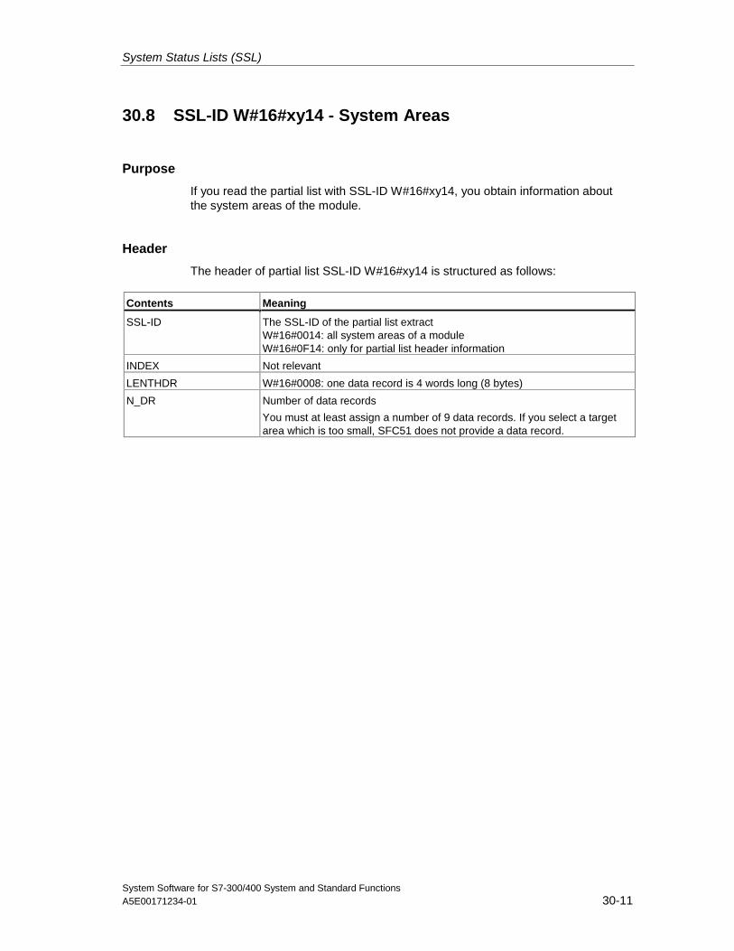
System Status Lists (SSL)
System Software for S7-300/400 System and Standard FunctionsA5E00171234-01 30-11
30.8 SSL-ID W#16#xy14 - System Areas
Purpose
If you read the partial list with SSL-ID W#16#xy14, you obtain information aboutthe system areas of the module.
Header
The header of partial list SSL-ID W#16#xy14 is structured as follows:
Contents Meaning
SSL-ID The SSL-ID of the partial list extractW#16#0014: all system areas of a moduleW#16#0F14: only for partial list header information
INDEX Not relevant
LENTHDR W#16#0008: one data record is 4 words long (8 bytes)
N_DR Number of data records
You must at least assign a number of 9 data records. If you select a targetarea which is too small, SFC51 does not provide a data record.
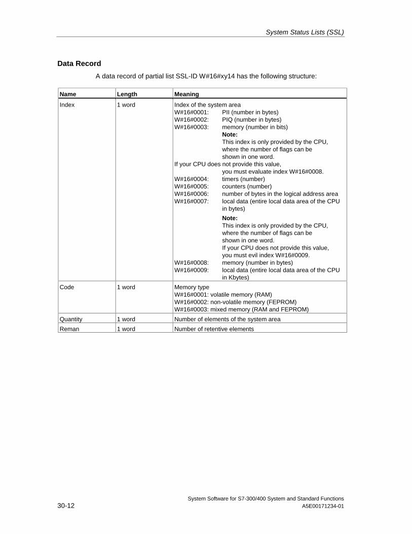
System Status Lists (SSL)
System Software for S7-300/400 System and Standard Functions30-12 A5E00171234-01
Data Record
A data record of partial list SSL-ID W#16#xy14 has the following structure:
Name Length Meaning
Index 1 word Index of the system areaW#16#0001: PII (number in bytes)W#16#0002: PIQ (number in bytes)W#16#0003: memory (number in bits)
Note:This index is only provided by the CPU,where the number of flags can beshown in one word.
If your CPU does not provide this value,you must evaluate index W#16#0008.
W#16#0004: timers (number)W#16#0005: counters (number)W#16#0006: number of bytes in the logical address areaW#16#0007: local data (entire local data area of the CPU
in bytes)
Note:This index is only provided by the CPU,where the number of flags can beshown in one word.If your CPU does not provide this value,you must evil index W#16#0009.
W#16#0008: memory (number in bytes)W#16#0009: local data (entire local data area of the CPU
in Kbytes)
Code 1 word Memory typeW#16#0001: volatile memory (RAM)W#16#0002: non-volatile memory (FEPROM)W#16#0003: mixed memory (RAM and FEPROM)
Quantity 1 word Number of elements of the system area
Reman 1 word Number of retentive elements
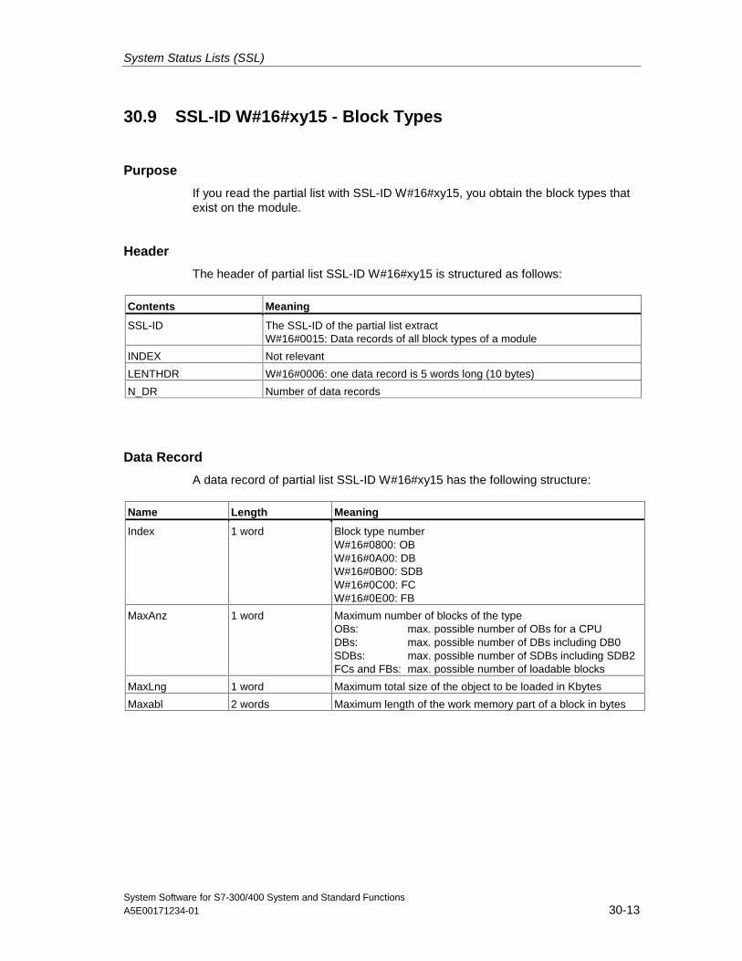
System Status Lists (SSL)
System Software for S7-300/400 System and Standard FunctionsA5E00171234-01 30-13
30.9 SSL-ID W#16#xy15 - Block Types
Purpose
If you read the partial list with SSL-ID W#16#xy15, you obtain the block types thatexist on the module.
Header
The header of partial list SSL-ID W#16#xy15 is structured as follows:
Contents Meaning
SSL-ID The SSL-ID of the partial list extractW#16#0015: Data records of all block types of a module
INDEX Not relevant
LENTHDR W#16#0006: one data record is 5 words long (10 bytes)
N_DR Number of data records
Data Record
A data record of partial list SSL-ID W#16#xy15 has the following structure:
Name Length Meaning
Index 1 word Block type numberW#16#0800: OBW#16#0A00: DBW#16#0B00: SDBW#16#0C00: FCW#16#0E00: FB
MaxAnz 1 word Maximum number of blocks of the typeOBs: max. possible number of OBs for a CPUDBs: max. possible number of DBs including DB0SDBs: max. possible number of SDBs including SDB2FCs and FBs: max. possible number of loadable blocks
MaxLng 1 word Maximum total size of the object to be loaded in Kbytes
Maxabl 2 words Maximum length of the work memory part of a block in bytes
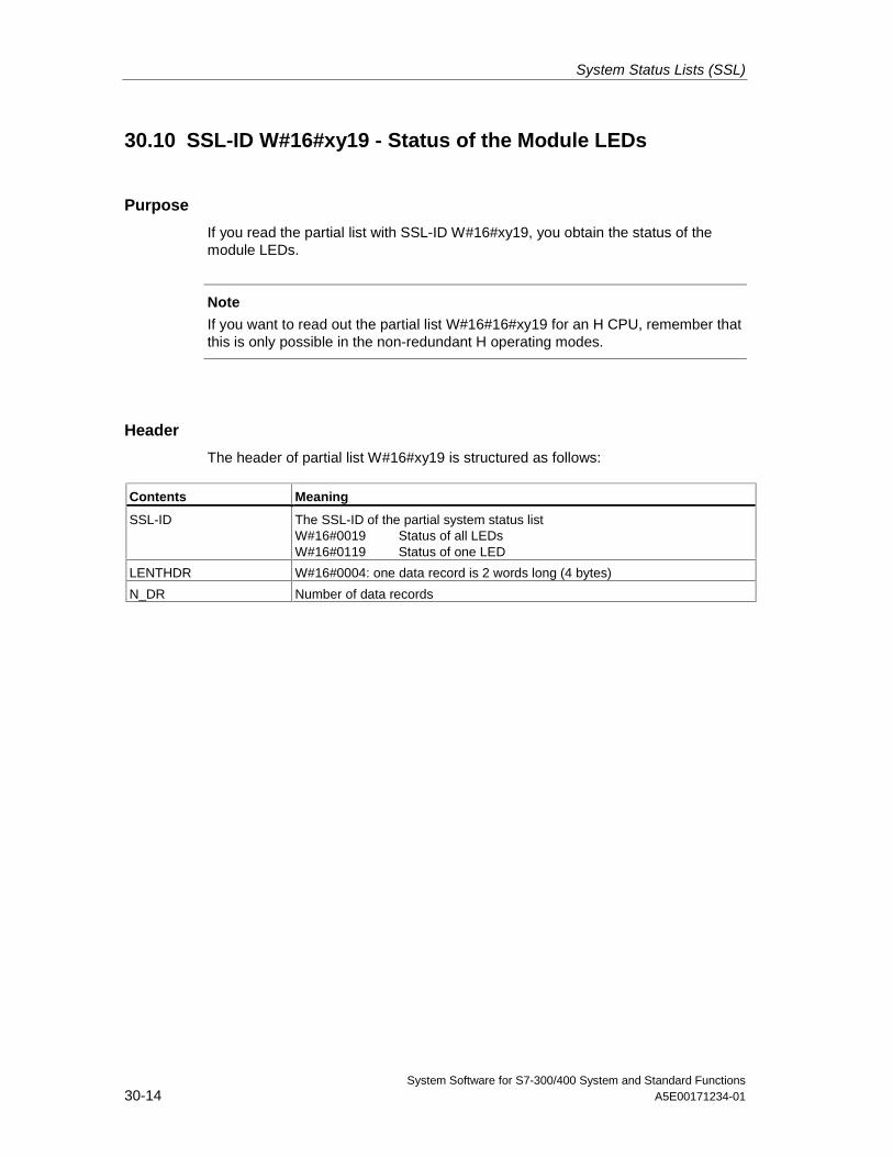
System Status Lists (SSL)
System Software for S7-300/400 System and Standard Functions30-14 A5E00171234-01
30.10 SSL-ID W#16#xy19 - Status of the Module LEDs
Purpose
If you read the partial list with SSL-ID W#16#xy19, you obtain the status of themodule LEDs.
Note
If you want to read out the partial list W#16#16#xy19 for an H CPU, remember thatthis is only possible in the non-redundant H operating modes.
Header
The header of partial list W#16#xy19 is structured as follows:
Contents Meaning
SSL-ID The SSL-ID of the partial system status listW#16#0019 Status of all LEDsW#16#0119 Status of one LED
LENTHDR W#16#0004: one data record is 2 words long (4 bytes)
N_DR Number of data records
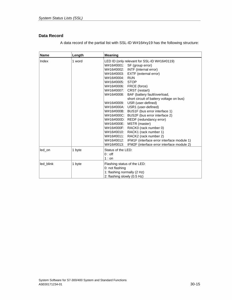
System Status Lists (SSL)
System Software for S7-300/400 System and Standard FunctionsA5E00171234-01 30-15
Data Record
A data record of the partial list with SSL-ID W#16#xy19 has the following structure:
Name Length Meaning
Index 1 word LED ID (only relevant for SSL-ID W#16#0119)W#16#0001: SF (group error)W#16#0002: INTF (internal error)W#16#0003: EXTF (external error)W#16#0004: RUNW#16#0005: STOPW#16#0006: FRCE (force)W#16#0007: CRST (restart)W#16#0008: BAF (battery fault/overload,
short circuit of battery voltage on bus)W#16#0009: USR (user-defined)W#16#000A: USR1 (user-defined)W#16#000B: BUS1F (bus error interface 1)W#16#000C: BUS2F (bus error interface 2)W#16#000D: REDF (redundancy error)W#16#000E: MSTR (master)W#16#000F: RACK0 (rack number 0)W#16#0010: RACK1 (rack number 1)W#16#0011: RACK2 (rack number 2)W#16#0012: IFM1F (interface error interface module 1)W#16#0013: IFM2F (interface error interface module 2)
led_on 1 byte Status of the LED:0 : off1 : on
led_blink 1 byte Flashing status of the LED:0: not flashing1: flashing normally (2 Hz)2: flashing slowly (0.5 Hz)
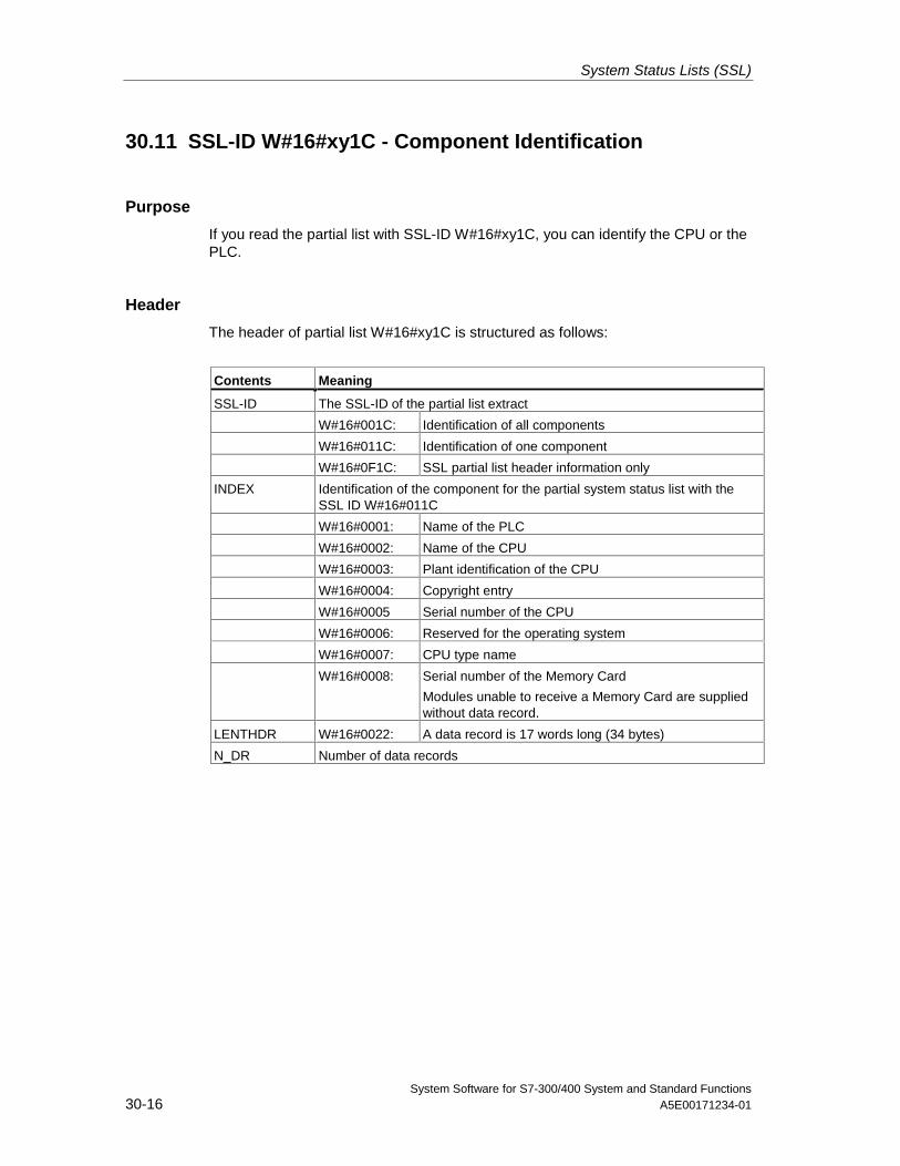
System Status Lists (SSL)
System Software for S7-300/400 System and Standard Functions30-16 A5E00171234-01
30.11 SSL-ID W#16#xy1C - Component Identification
Purpose
If you read the partial list with SSL-ID W#16#xy1C, you can identify the CPU or thePLC.
Header
The header of partial list W#16#xy1C is structured as follows:
Contents Meaning
SSL-ID The SSL-ID of the partial list extract
W#16#001C: Identification of all components
W#16#011C: Identification of one component
W#16#0F1C: SSL partial list header information only
INDEX Identification of the component for the partial system status list with theSSL ID W#16#011C
W#16#0001: Name of the PLC
W#16#0002: Name of the CPU
W#16#0003: Plant identification of the CPU
W#16#0004: Copyright entry
W#16#0005 Serial number of the CPU
W#16#0006: Reserved for the operating system
W#16#0007: CPU type name
W#16#0008: Serial number of the Memory Card
Modules unable to receive a Memory Card are suppliedwithout data record.
LENTHDR W#16#0022: A data record is 17 words long (34 bytes)
N_DR Number of data records
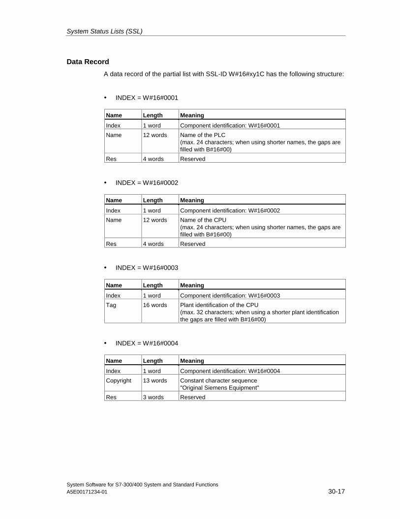
System Status Lists (SSL)
System Software for S7-300/400 System and Standard FunctionsA5E00171234-01 30-17
Data Record
A data record of the partial list with SSL-ID W#16#xy1C has the following structure:
• INDEX = W#16#0001
Name Length Meaning
Index 1 word Component identification: W#16#0001
Name 12 words Name of the PLC(max. 24 characters; when using shorter names, the gaps arefilled with B#16#00)
Res 4 words Reserved
• INDEX = W#16#0002
Name Length Meaning
Index 1 word Component identification: W#16#0002
Name 12 words Name of the CPU(max. 24 characters; when using shorter names, the gaps arefilled with B#16#00)
Res 4 words Reserved
• INDEX = W#16#0003
Name Length Meaning
Index 1 word Component identification: W#16#0003
Tag 16 words Plant identification of the CPU(max. 32 characters; when using a shorter plant identificationthe gaps are filled with B#16#00)
• INDEX = W#16#0004
Name Length Meaning
Index 1 word Component identification: W#16#0004
Copyright 13 words Constant character sequence"Original Siemens Equipment"
Res 3 words Reserved
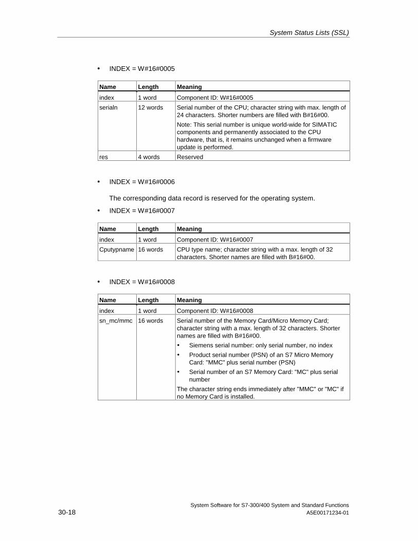
System Status Lists (SSL)
System Software for S7-300/400 System and Standard Functions30-18 A5E00171234-01
• INDEX = W#16#0005
Name Length Meaning
index 1 word Component ID: W#16#0005
serialn 12 words Serial number of the CPU; character string with max. length of24 characters. Shorter numbers are filled with B#16#00.
Note: This serial number is unique world-wide for SIMATICcomponents and permanently associated to the CPUhardware, that is, it remains unchanged when a firmwareupdate is performed.
res 4 words Reserved
• INDEX = W#16#0006
The corresponding data record is reserved for the operating system.
• INDEX = W#16#0007
Name Length Meaning
index 1 word Component ID: W#16#0007
Cputypname 16 words CPU type name; character string with a max. length of 32characters. Shorter names are filled with B#16#00.
• INDEX = W#16#0008
Name Length Meaning
index 1 word Component ID: W#16#0008
sn_mc/mmc 16 words Serial number of the Memory Card/Micro Memory Card;character string with a max. length of 32 characters. Shorternames are filled with B#16#00.
• Siemens serial number: only serial number, no index
• Product serial number (PSN) of an S7 Micro MemoryCard: "MMC" plus serial number (PSN)
• Serial number of an S7 Memory Card: "MC" plus serialnumber
The character string ends immediately after "MMC" or "MC" ifno Memory Card is installed.
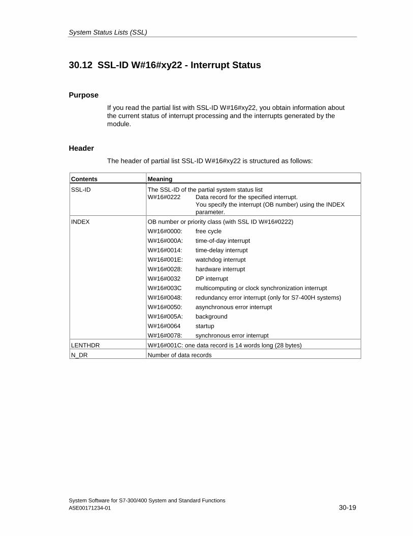
System Status Lists (SSL)
System Software for S7-300/400 System and Standard FunctionsA5E00171234-01 30-19
30.12 SSL-ID W#16#xy22 - Interrupt Status
Purpose
If you read the partial list with SSL-ID W#16#xy22, you obtain information aboutthe current status of interrupt processing and the interrupts generated by themodule.
Header
The header of partial list SSL-ID W#16#xy22 is structured as follows:
Contents Meaning
SSL-ID The SSL-ID of the partial system status listW#16#0222 Data record for the specified interrupt.
You specify the interrupt (OB number) using the INDEXparameter.
INDEX OB number or priority class (with SSL ID W#16#0222)
W#16#0000: free cycle
W#16#000A: time-of-day interrupt
W#16#0014: time-delay interrupt
W#16#001E: watchdog interrupt
W#16#0028: hardware interrupt
W#16#0032 DP interrupt
W#16#003C multicomputing or clock synchronization interrupt
W#16#0048: redundancy error interrupt (only for S7-400H systems)
W#16#0050: asynchronous error interrupt
W#16#005A: background
W#16#0064 startup
W#16#0078: synchronous error interrupt
LENTHDR W#16#001C: one data record is 14 words long (28 bytes)
N_DR Number of data records
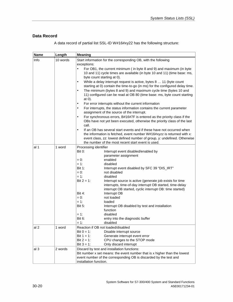
System Status Lists (SSL)
System Software for S7-300/400 System and Standard Functions30-20 A5E00171234-01
Data Record
A data record of partial list SSL-ID W#16#xy22 has the following structure:
Name Length Meaning
Info 10 words Start information for the corresponding OB, with the followingexceptions:• For OB1, the current minimum ( in byte 8 and 9) and maximum (in byte
10 and 11) cycle times are available (in byte 10 and 11) (time base: ms,byte count starting at 0).
• While a delay interrupt request is active, bytes 8 … 11 (byte countstarting at 0) contain the time-to-go (in ms) for the configured delay time.
• The minimum (bytes 8 and 9) and maximum cycle time (bytes 10 and11) configured can be read at OB 80 (time base: ms, byte count startingat 0).
• For error interrupts without the current information• For interrupts, the status information contains the current parameter
assignment of the source of the interrupt.• For synchronous errors, B#16#7F is entered as the priority class if the
OBs have not yet been executed, otherwise the priority class of the lastcall.
• If an OB has several start events and if these have not occurred whenthe information is fetched, event number W#16#xyzz is returned with x:event class, zz: lowest defined number of group, y: undefined. Otherwisethe number of the most recent start event is used.
al 1 1 word Processing identifierBit 0: Interrupt event disabled/enabled by
parameter assignment= 0: enabled= 1: disabledBit 1: Interrupt event disabled by SFC 39 "DIS_IRT"= 0: not disabled= 1: disabledBit 2 = 1: Interrupt source is active (generate job exists for time
interrupts, time-of-day interrupt OB started, time-delayinterrupt OB started, cyclic interrupt OB: time started)
Bit 4: Interrupt OB= 0: not loaded= 1: loadedBit 5: Interrupt OB disabled by test and installation
function= 1: disabledBit 6: entry into the diagnostic buffer= 1: disabled
al 2 1 word Reaction if OB not loaded/disabledBit 0 = 1: Disable interrupt sourceBit 1 = 1: Generate interrupt event errorBit 2 = 1: CPU changes to the STOP modeBit 3 = 1: Only discard interrupt
al 3 2 words Discard by test and installation functions:Bit number x set means: the event number that is x higher than the lowestevent number of the corresponding OB is discarded by the test andinstallation function.
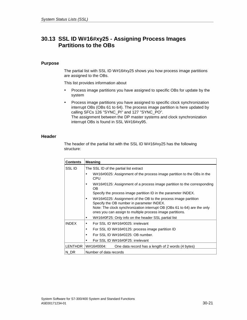
System Status Lists (SSL)
System Software for S7-300/400 System and Standard FunctionsA5E00171234-01 30-21
30.13 SSL ID W#16#xy25 - Assigning Process ImagesPartitions to the OBs
Purpose
The partial list with SSL ID W#16#xy25 shows you how process image partitionsare assigned to the OBs.
This list provides information about
• Process image partitions you have assigned to specific OBs for update by thesystem
• Process image partitions you have assigned to specific clock synchronizationinterrupt OBs (OBs 61 to 64). The process image partition is here updated bycalling SFCs 126 "SYNC_PI" and 127 "SYNC_PO".The assignment between the DP master systems and clock synchronizationinterrupt OBs is found in SSL W#16#xy95.
Header
The header of the partial list with the SSL ID W#16#xy25 has the followingstructure:
Contents Meaning
SSL ID The SSL ID of the partial list extract
• W#16#0025: Assignment of the process image partition to the OBs in theCPU
• W#16#0125: Assignment of a process image partition to the correspondingOBSpecify the process image partition ID in the parameter INDEX.
• W#16#0225: Assignment of the OB to the process image partitionSpecify the OB number in parameter INDEX.Note: The clock synchronization interrupt OB (OBs 61 to 64) are the onlyones you can assign to multiple process image partitions.
• W#16#0F25: Only info on the header SSL partial list
INDEX • For SSL ID W#16#0025: irrelevant
• For SSL ID W#16#0125: process image partition ID
• For SSL ID W#16#0225: OB number.
• For SSL ID W#16#0F25: irrelevant
LENTHDR W#16#0004: One data record has a length of 2 words (4 bytes)
N_DR Number of data records
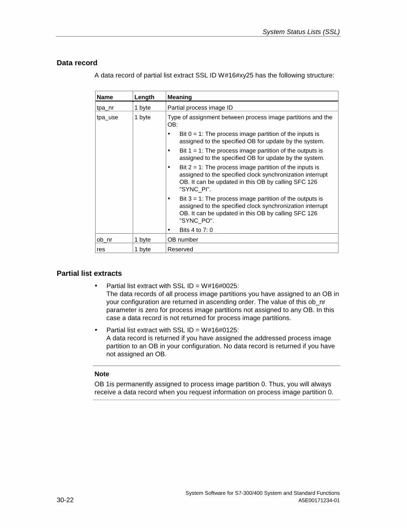
System Status Lists (SSL)
System Software for S7-300/400 System and Standard Functions30-22 A5E00171234-01
Data record
A data record of partial list extract SSL ID W#16#xy25 has the following structure:
Name Length Meaning
tpa_nr 1 byte Partial process image ID
tpa_use 1 byte Type of assignment between process image partitions and theOB:
• Bit 0 = 1: The process image partition of the inputs isassigned to the specified OB for update by the system.
• Bit 1 = 1: The process image partition of the outputs isassigned to the specified OB for update by the system.
• Bit 2 = 1: The process image partition of the inputs isassigned to the specified clock synchronization interruptOB. It can be updated in this OB by calling SFC 126"SYNC_PI".
• Bit 3 = 1: The process image partition of the outputs isassigned to the specified clock synchronization interruptOB. It can be updated in this OB by calling SFC 126"SYNC_PO".
• Bits 4 to 7: 0
ob_nr 1 byte OB number
res 1 byte Reserved
Partial list extracts
• Partial list extract with SSL ID = W#16#0025:The data records of all process image partitions you have assigned to an OB inyour configuration are returned in ascending order. The value of this ob_nrparameter is zero for process image partitions not assigned to any OB. In thiscase a data record is not returned for process image partitions.
• Partial list extract with SSL ID = W#16#0125:A data record is returned if you have assigned the addressed process imagepartition to an OB in your configuration. No data record is returned if you havenot assigned an OB.
Note
OB 1is permanently assigned to process image partition 0. Thus, you will alwaysreceive a data record when you request information on process image partition 0.
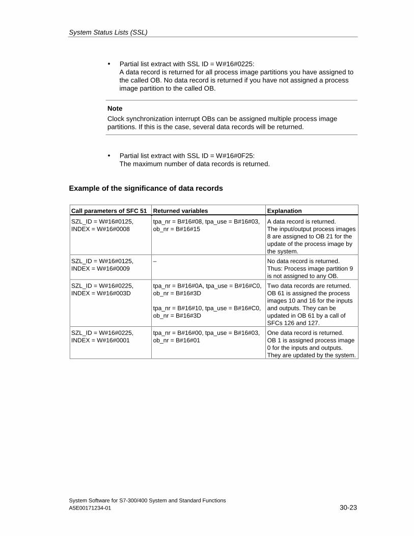
System Status Lists (SSL)
System Software for S7-300/400 System and Standard FunctionsA5E00171234-01 30-23
• Partial list extract with SSL ID = W#16#0225:A data record is returned for all process image partitions you have assigned tothe called OB. No data record is returned if you have not assigned a processimage partition to the called OB.
Note
Clock synchronization interrupt OBs can be assigned multiple process imagepartitions. If this is the case, several data records will be returned.
• Partial list extract with SSL ID = W#16#0F25:The maximum number of data records is returned.
Example of the significance of data records
Call parameters of SFC 51 Returned variables Explanation
SZL_ID = W#16#0125,INDEX = W#16#0008
tpa_nr = B#16#08, tpa_use = B#16#03,ob_nr = B#16#15
A data record is returned.The input/output process images8 are assigned to OB 21 for theupdate of the process image bythe system.
SZL_ID = W#16#0125,INDEX = W#16#0009
– No data record is returned.Thus: Process image partition 9is not assigned to any OB.
SZL_ID = W#16#0225,INDEX = W#16#003D
tpa_nr = B#16#0A, tpa_use = B#16#C0,ob_nr = B#16#3D
tpa_nr = B#16#10, tpa_use = B#16#C0,ob_nr = B#16#3D
Two data records are returned.OB 61 is assigned the processimages 10 and 16 for the inputsand outputs. They can beupdated in OB 61 by a call ofSFCs 126 and 127.
SZL_ID = W#16#0225,INDEX = W#16#0001
tpa_nr = B#16#00, tpa_use = B#16#03,ob_nr = B#16#01
One data record is returned.OB 1 is assigned process image0 for the inputs and outputs.They are updated by the system.
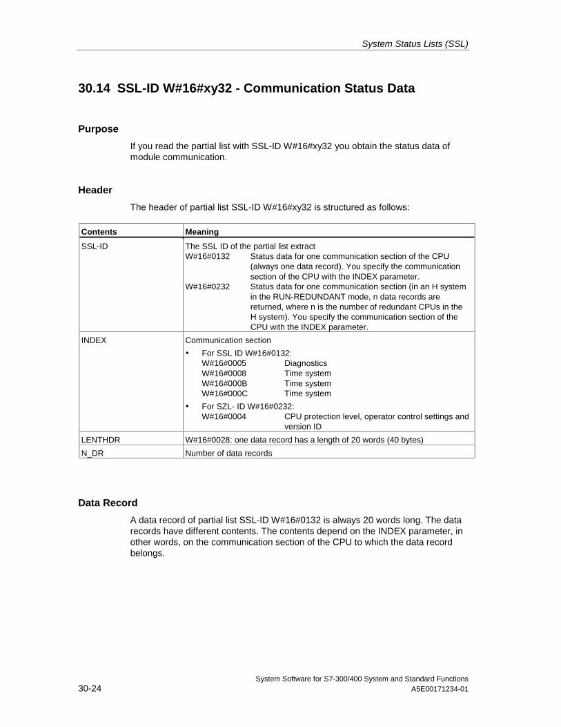
System Status Lists (SSL)
System Software for S7-300/400 System and Standard Functions30-24 A5E00171234-01
30.14 SSL-ID W#16#xy32 - Communication Status Data
Purpose
If you read the partial list with SSL-ID W#16#xy32 you obtain the status data ofmodule communication.
Header
The header of partial list SSL-ID W#16#xy32 is structured as follows:
Contents Meaning
SSL-ID The SSL ID of the partial list extractW#16#0132 Status data for one communication section of the CPU
(always one data record). You specify the communicationsection of the CPU with the INDEX parameter.
W#16#0232 Status data for one communication section (in an H systemin the RUN-REDUNDANT mode, n data records arereturned, where n is the number of redundant CPUs in theH system). You specify the communication section of theCPU with the INDEX parameter.
INDEX Communication section
• For SSL ID W#16#0132:W#16#0005 DiagnosticsW#16#0008 Time systemW#16#000B Time systemW#16#000C Time system
• For SZL- ID W#16#0232:W#16#0004 CPU protection level, operator control settings and
version ID
LENTHDR W#16#0028: one data record has a length of 20 words (40 bytes)
N_DR Number of data records
Data Record
A data record of partial list SSL-ID W#16#0132 is always 20 words long. The datarecords have different contents. The contents depend on the INDEX parameter, inother words, on the communication section of the CPU to which the data recordbelongs.
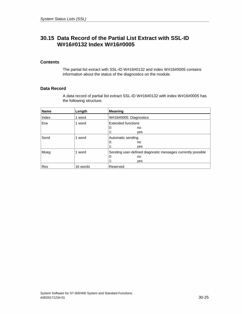
System Status Lists (SSL)
System Software for S7-300/400 System and Standard FunctionsA5E00171234-01 30-25
30.15 Data Record of the Partial List Extract with SSL-IDW#16#0132 Index W#16#0005
Contents
The partial list extract with SSL-ID W#16#0132 and index W#16#0005 containsinformation about the status of the diagnostics on the module.
Data Record
A data record of partial list extract SSL-ID W#16#0132 with index W#16#0005 hasthe following structure:
Name Length Meaning
Index 1 word W#16#0005: Diagnostics
Erw 1 word Extended functions0: no1: yes
Send 1 word Automatic sending0: no1: yes
Moeg 1 word Sending user-defined diagnostic messages currently possible0: no1: yes
Res 16 words Reserved
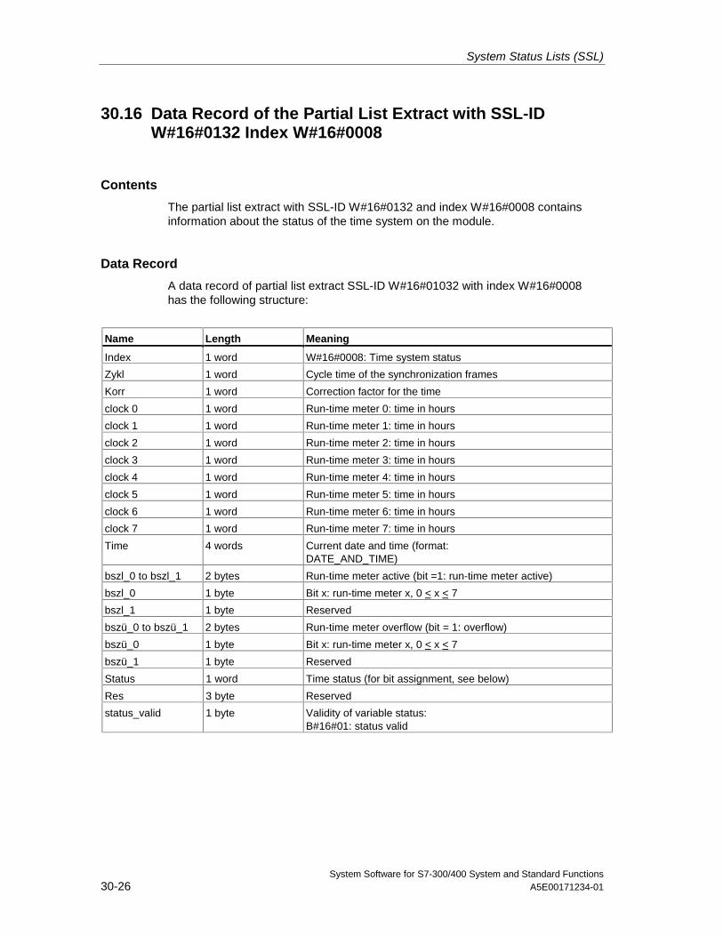
System Status Lists (SSL)
System Software for S7-300/400 System and Standard Functions30-26 A5E00171234-01
30.16 Data Record of the Partial List Extract with SSL-IDW#16#0132 Index W#16#0008
Contents
The partial list extract with SSL-ID W#16#0132 and index W#16#0008 containsinformation about the status of the time system on the module.
Data Record
A data record of partial list extract SSL-ID W#16#01032 with index W#16#0008has the following structure:
Name Length Meaning
Index 1 word W#16#0008: Time system status
Zykl 1 word Cycle time of the synchronization frames
Korr 1 word Correction factor for the time
clock 0 1 word Run-time meter 0: time in hours
clock 1 1 word Run-time meter 1: time in hours
clock 2 1 word Run-time meter 2: time in hours
clock 3 1 word Run-time meter 3: time in hours
clock 4 1 word Run-time meter 4: time in hours
clock 5 1 word Run-time meter 5: time in hours
clock 6 1 word Run-time meter 6: time in hours
clock 7 1 word Run-time meter 7: time in hours
Time 4 words Current date and time (format:DATE_AND_TIME)
bszl_0 to bszl_1 2 bytes Run-time meter active (bit =1: run-time meter active)
bszl_0 1 byte Bit x: run-time meter x, 0 < x < 7
bszl_1 1 byte Reserved
bszü_0 to bszü_1 2 bytes Run-time meter overflow (bit = 1: overflow)
bszü_0 1 byte Bit x: run-time meter x, 0 < x < 7
bszü_1 1 byte Reserved
Status 1 word Time status (for bit assignment, see below)
Res 3 byte Reserved
status_valid 1 byte Validity of variable status:B#16#01: status valid
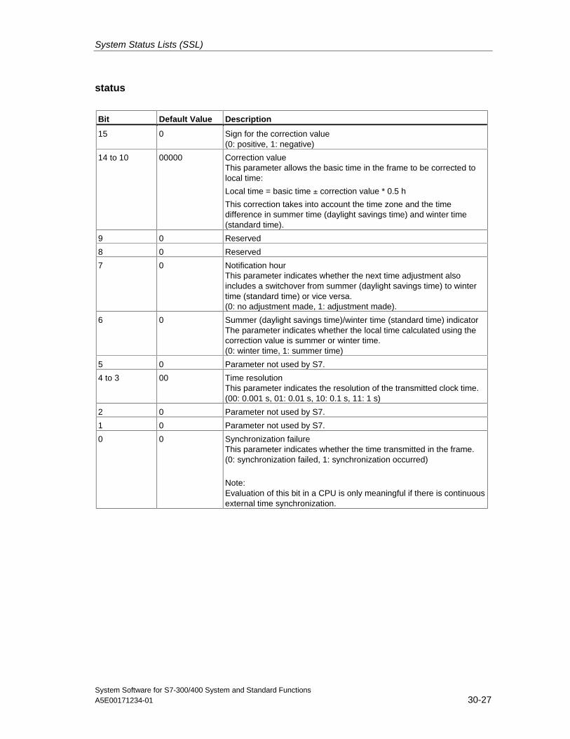
System Status Lists (SSL)
System Software for S7-300/400 System and Standard FunctionsA5E00171234-01 30-27
status
Bit Default Value Description
15 0 Sign for the correction value(0: positive, 1: negative)
14 to 10 00000 Correction valueThis parameter allows the basic time in the frame to be corrected tolocal time:
Local time = basic time ± correction value * 0.5 h
This correction takes into account the time zone and the timedifference in summer time (daylight savings time) and winter time(standard time).
9 0 Reserved
8 0 Reserved
7 0 Notification hourThis parameter indicates whether the next time adjustment alsoincludes a switchover from summer (daylight savings time) to wintertime (standard time) or vice versa.(0: no adjustment made, 1: adjustment made).
6 0 Summer (daylight savings time)/winter time (standard time) indicatorThe parameter indicates whether the local time calculated using thecorrection value is summer or winter time.(0: winter time, 1: summer time)
5 0 Parameter not used by S7.
4 to 3 00 Time resolutionThis parameter indicates the resolution of the transmitted clock time.(00: 0.001 s, 01: 0.01 s, 10: 0.1 s, 11: 1 s)
2 0 Parameter not used by S7.
1 0 Parameter not used by S7.
0 0 Synchronization failureThis parameter indicates whether the time transmitted in the frame.(0: synchronization failed, 1: synchronization occurred)
Note:Evaluation of this bit in a CPU is only meaningful if there is continuousexternal time synchronization.
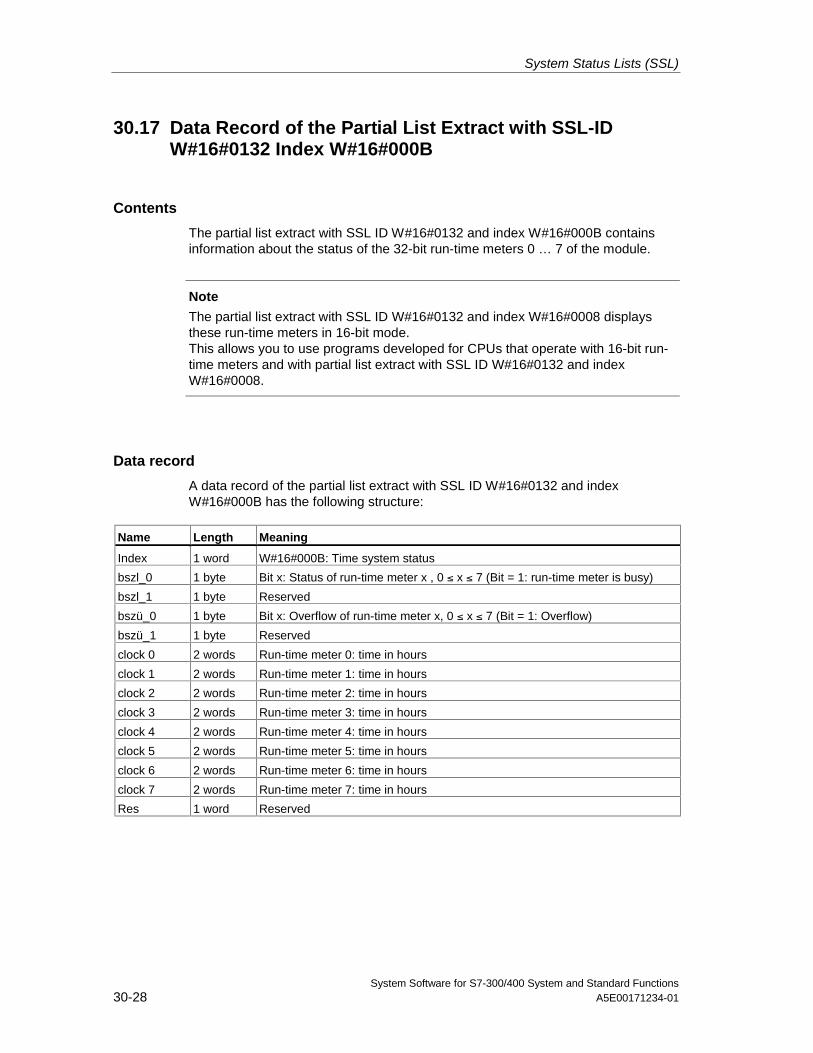
System Status Lists (SSL)
System Software for S7-300/400 System and Standard Functions30-28 A5E00171234-01
30.17 Data Record of the Partial List Extract with SSL-IDW#16#0132 Index W#16#000B
Contents
The partial list extract with SSL ID W#16#0132 and index W#16#000B containsinformation about the status of the 32-bit run-time meters 0 … 7 of the module.
Note
The partial list extract with SSL ID W#16#0132 and index W#16#0008 displaysthese run-time meters in 16-bit mode.This allows you to use programs developed for CPUs that operate with 16-bit run-time meters and with partial list extract with SSL ID W#16#0132 and indexW#16#0008.
Data record
A data record of the partial list extract with SSL ID W#16#0132 and indexW#16#000B has the following structure:
Name Length Meaning
Index 1 word W#16#000B: Time system status
bszl_0 1 byte Bit x: Status of run-time meter x , 0 ≤ x ≤ 7 (Bit = 1: run-time meter is busy)
bszl_1 1 byte Reserved
bszü_0 1 byte Bit x: Overflow of run-time meter x, 0 ≤ x ≤ 7 (Bit = 1: Overflow)
bszü_1 1 byte Reserved
clock 0 2 words Run-time meter 0: time in hours
clock 1 2 words Run-time meter 1: time in hours
clock 2 2 words Run-time meter 2: time in hours
clock 3 2 words Run-time meter 3: time in hours
clock 4 2 words Run-time meter 4: time in hours
clock 5 2 words Run-time meter 5: time in hours
clock 6 2 words Run-time meter 6: time in hours
clock 7 2 words Run-time meter 7: time in hours
Res 1 word Reserved
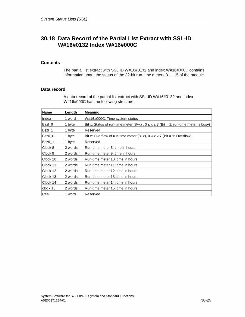
System Status Lists (SSL)
System Software for S7-300/400 System and Standard FunctionsA5E00171234-01 30-29
30.18 Data Record of the Partial List Extract with SSL-IDW#16#0132 Index W#16#000C
Contents
The partial list extract with SSL ID W#16#0132 and index W#16#000C containsinformation about the status of the 32-bit run-time meters 8 … 15 of the module.
Data record
A data record of the partial list extract with SSL ID W#16#0132 and indexW#16#000C has the following structure:
Name Length Meaning
Index 1 word W#16#000C: Time system status
Bszl_0 1 byte Bit x: Status of run-time meter (8+x) , 0 ≤ x ≤ 7 (Bit = 1: run-time meter is busy)
Bszl_1 1 byte Reserved
Bszü_0 1 byte Bit x: Overflow of run-time meter (8+x), 0 ≤ x ≤ 7 (Bit = 1: Overflow)
Bszü_1 1 byte Reserved
Clock 8 2 words Run-time meter 8: time in hours
Clock 9 2 words Run-time meter 9: time in hours
Clock 10 2 words Run-time meter 10: time in hours
Clock 11 2 words Run-time meter 11: time in hours
Clock 12 2 words Run-time meter 12: time in hours
Clock 13 2 words Run-time meter 13: time in hours
Clock 14 2 words Run-time meter 14: time in hours
clock 15 2 words Run-time meter 15: time in hours
Res 1 word Reserved
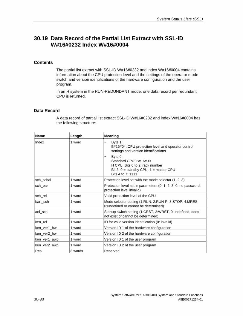
System Status Lists (SSL)
System Software for S7-300/400 System and Standard Functions30-30 A5E00171234-01
30.19 Data Record of the Partial List Extract with SSL-IDW#16#0232 Index W#16#0004
Contents
The partial list extract with SSL-ID W#16#0232 and index W#16#0004 containsinformation about the CPU protection level and the settings of the operator modeswitch and version identifications of the hardware configuration and the userprogram.
In an H system in the RUN-REDUNDANT mode, one data record per redundantCPU is returned.
Data Record
A data record of partial list extract SSL-ID W#16#0232 and index W#16#0004 hasthe following structure:
Name Length Meaning
Index 1 word • Byte 1:B#16#04: CPU protection level and operator controlsettings and version identifications
• Byte 0:Standard CPU: B#16#00H CPU: Bits 0 to 2: rack numberBit 3: 0 = standby CPU, 1 = master CPUBits 4 to 7: 1111
sch_schal 1 word Protection level set with the mode selector (1, 2, 3)
sch_par 1 word Protection level set in parameters (0, 1, 2, 3; 0: no password,protection level invalid)
sch_rel 1 word Valid protection level of the CPU
bart_sch 1 word Mode selector setting (1:RUN, 2:RUN-P, 3:STOP, 4:MRES,0:undefined or cannot be determined)
anl_sch 1 word Startup switch setting (1:CRST, 2:WRST, 0:undefined, doesnot exist of cannot be determined)
ken_rel 1 word ID for valid version identification (0: invalid)
ken_ver1_hw 1 word Version ID 1 of the hardware configuration
ken_ver2_hw 1 word Version ID 2 of the hardware configuration
ken_ver1_awp 1 word Version ID 1 of the user program
ken_ver2_awp 1 word Version ID 2 of the user program
Res 8 words Reserved
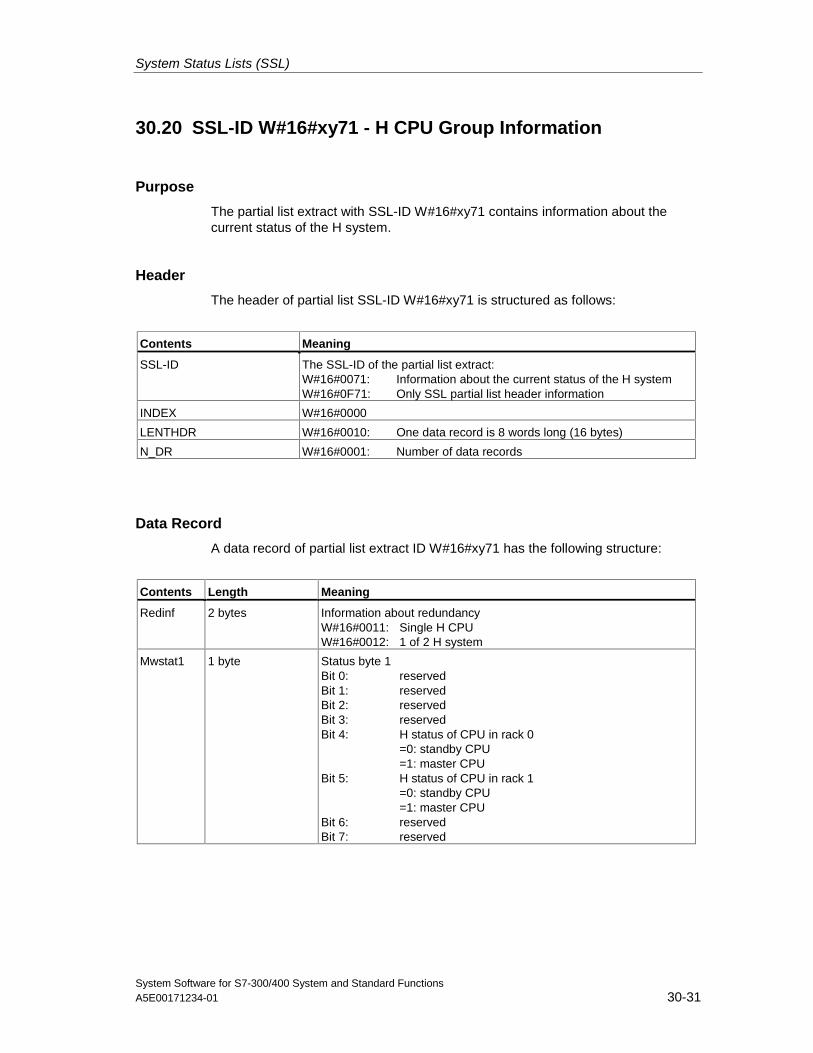
System Status Lists (SSL)
System Software for S7-300/400 System and Standard FunctionsA5E00171234-01 30-31
30.20 SSL-ID W#16#xy71 - H CPU Group Information
Purpose
The partial list extract with SSL-ID W#16#xy71 contains information about thecurrent status of the H system.
Header
The header of partial list SSL-ID W#16#xy71 is structured as follows:
Contents Meaning
SSL-ID The SSL-ID of the partial list extract:W#16#0071: Information about the current status of the H systemW#16#0F71: Only SSL partial list header information
INDEX W#16#0000
LENTHDR W#16#0010: One data record is 8 words long (16 bytes)
N_DR W#16#0001: Number of data records
Data Record
A data record of partial list extract ID W#16#xy71 has the following structure:
Contents Length Meaning
Redinf 2 bytes Information about redundancyW#16#0011: Single H CPUW#16#0012: 1 of 2 H system
Mwstat1 1 byte Status byte 1Bit 0: reservedBit 1: reservedBit 2: reservedBit 3: reservedBit 4: H status of CPU in rack 0
=0: standby CPU=1: master CPU
Bit 5: H status of CPU in rack 1=0: standby CPU=1: master CPU
Bit 6: reservedBit 7: reserved
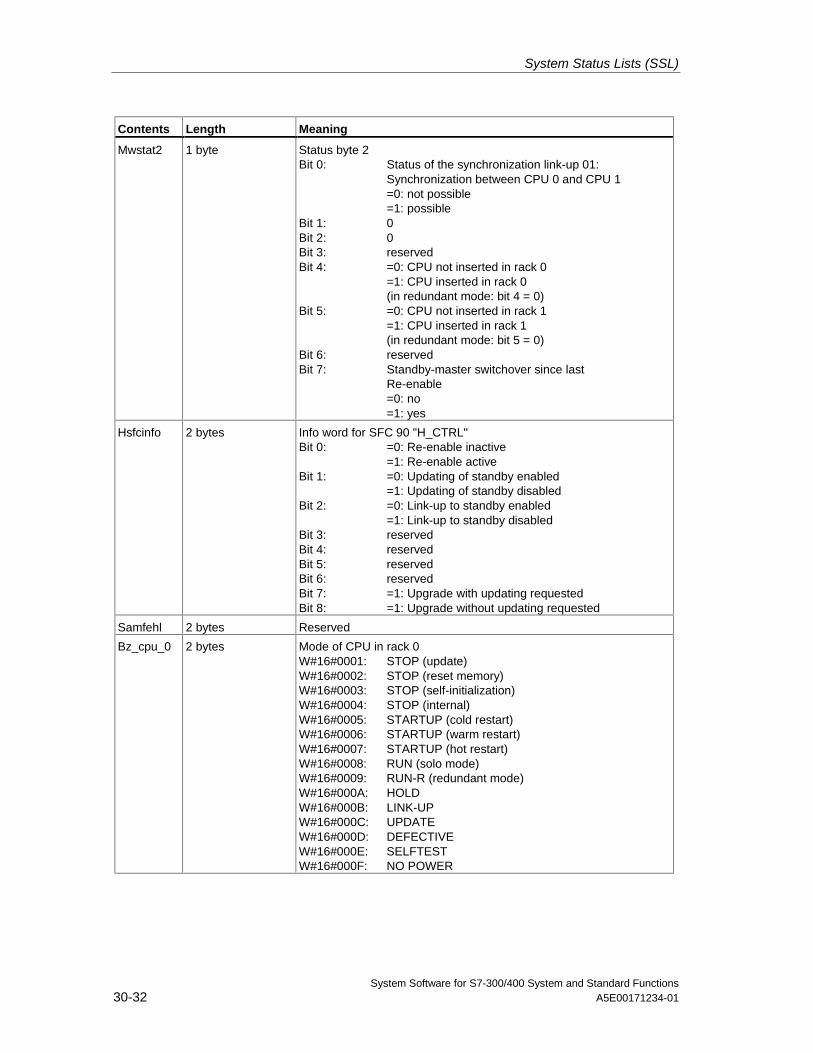
System Status Lists (SSL)
System Software for S7-300/400 System and Standard Functions30-32 A5E00171234-01
Contents Length Meaning
Mwstat2 1 byte Status byte 2Bit 0: Status of the synchronization link-up 01:
Synchronization between CPU 0 and CPU 1=0: not possible=1: possible
Bit 1: 0Bit 2: 0Bit 3: reservedBit 4: =0: CPU not inserted in rack 0
=1: CPU inserted in rack 0(in redundant mode: bit 4 = 0)
Bit 5: =0: CPU not inserted in rack 1=1: CPU inserted in rack 1(in redundant mode: bit 5 = 0)
Bit 6: reservedBit 7: Standby-master switchover since last
Re-enable=0: no=1: yes
Hsfcinfo 2 bytes Info word for SFC 90 "H_CTRL"Bit 0: =0: Re-enable inactive
=1: Re-enable activeBit 1: =0: Updating of standby enabled
=1: Updating of standby disabledBit 2: =0: Link-up to standby enabled
=1: Link-up to standby disabledBit 3: reservedBit 4: reservedBit 5: reservedBit 6: reservedBit 7: =1: Upgrade with updating requestedBit 8: =1: Upgrade without updating requested
Samfehl 2 bytes Reserved
Bz_cpu_0 2 bytes Mode of CPU in rack 0W#16#0001: STOP (update)W#16#0002: STOP (reset memory)W#16#0003: STOP (self-initialization)W#16#0004: STOP (internal)W#16#0005: STARTUP (cold restart)W#16#0006: STARTUP (warm restart)W#16#0007: STARTUP (hot restart)W#16#0008: RUN (solo mode)W#16#0009: RUN-R (redundant mode)W#16#000A: HOLDW#16#000B: LINK-UPW#16#000C: UPDATEW#16#000D: DEFECTIVEW#16#000E: SELFTESTW#16#000F: NO POWER
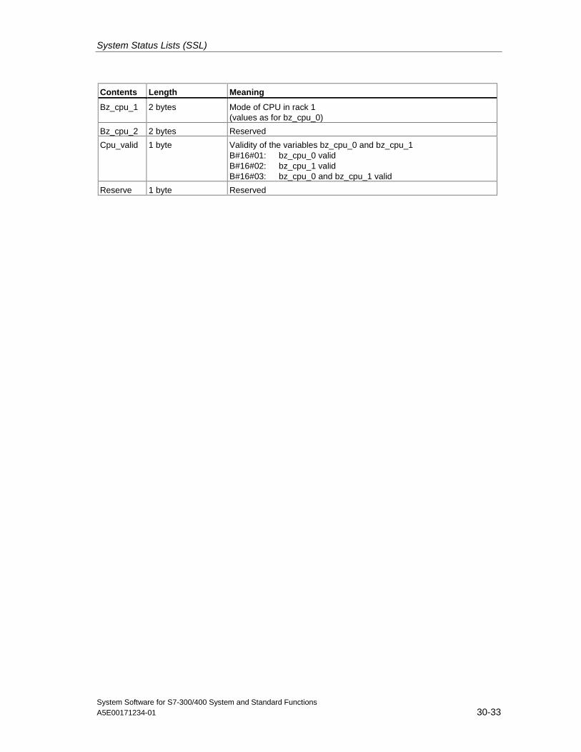
System Status Lists (SSL)
System Software for S7-300/400 System and Standard FunctionsA5E00171234-01 30-33
Contents Length Meaning
Bz_cpu_1 2 bytes Mode of CPU in rack 1(values as for bz_cpu_0)
Bz_cpu_2 2 bytes Reserved
Cpu_valid 1 byte Validity of the variables bz_cpu_0 and bz_cpu_1B#16#01: bz_cpu_0 validB#16#02: bz_cpu_1 validB#16#03: bz_cpu_0 and bz_cpu_1 valid
Reserve 1 byte Reserved
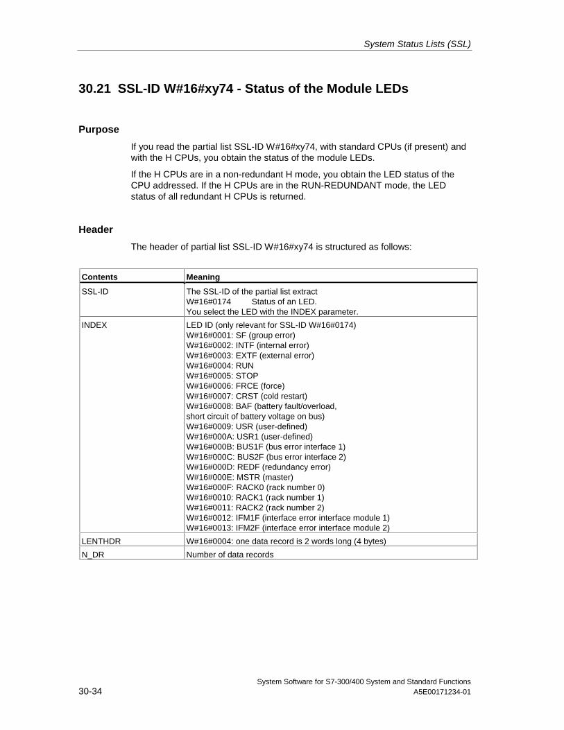
System Status Lists (SSL)
System Software for S7-300/400 System and Standard Functions30-34 A5E00171234-01
30.21 SSL-ID W#16#xy74 - Status of the Module LEDs
Purpose
If you read the partial list SSL-ID W#16#xy74, with standard CPUs (if present) andwith the H CPUs, you obtain the status of the module LEDs.
If the H CPUs are in a non-redundant H mode, you obtain the LED status of theCPU addressed. If the H CPUs are in the RUN-REDUNDANT mode, the LEDstatus of all redundant H CPUs is returned.
Header
The header of partial list SSL-ID W#16#xy74 is structured as follows:
Contents Meaning
SSL-ID The SSL-ID of the partial list extractW#16#0174 Status of an LED.You select the LED with the INDEX parameter.
INDEX LED ID (only relevant for SSL-ID W#16#0174)W#16#0001: SF (group error)W#16#0002: INTF (internal error)W#16#0003: EXTF (external error)W#16#0004: RUNW#16#0005: STOPW#16#0006: FRCE (force)W#16#0007: CRST (cold restart)W#16#0008: BAF (battery fault/overload,short circuit of battery voltage on bus)W#16#0009: USR (user-defined)W#16#000A: USR1 (user-defined)W#16#000B: BUS1F (bus error interface 1)W#16#000C: BUS2F (bus error interface 2)W#16#000D: REDF (redundancy error)W#16#000E: MSTR (master)W#16#000F: RACK0 (rack number 0)W#16#0010: RACK1 (rack number 1)W#16#0011: RACK2 (rack number 2)W#16#0012: IFM1F (interface error interface module 1)W#16#0013: IFM2F (interface error interface module 2)
LENTHDR W#16#0004: one data record is 2 words long (4 bytes)
N_DR Number of data records
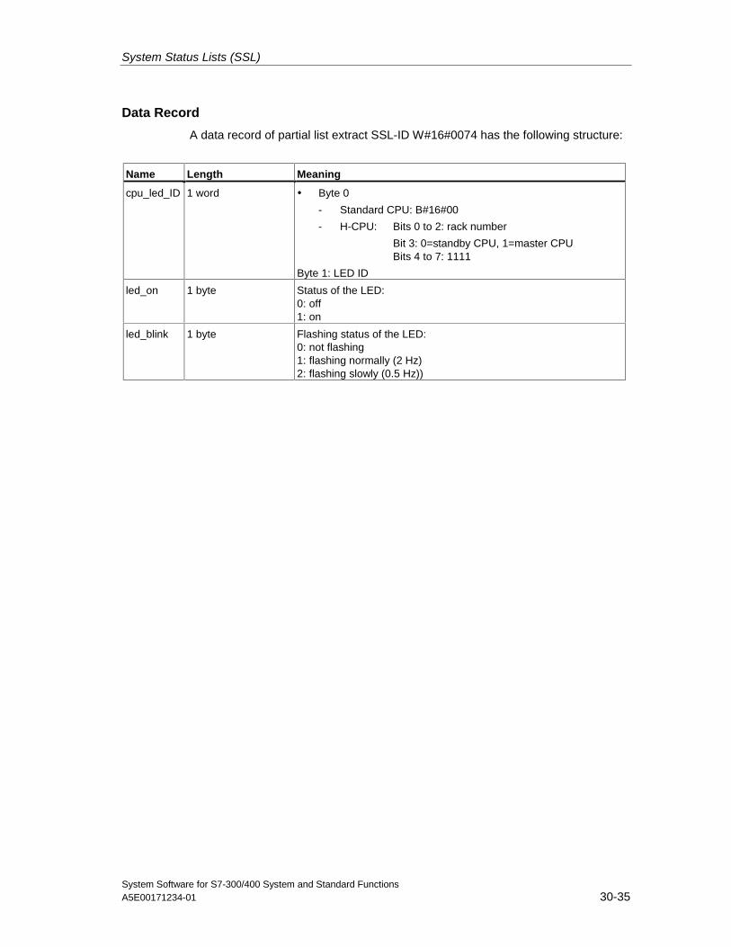
System Status Lists (SSL)
System Software for S7-300/400 System and Standard FunctionsA5E00171234-01 30-35
Data Record
A data record of partial list extract SSL-ID W#16#0074 has the following structure:
Name Length Meaning
cpu_led_ID 1 word • Byte 0
- Standard CPU: B#16#00
- H-CPU: Bits 0 to 2: rack number
Bit 3: 0=standby CPU, 1=master CPUBits 4 to 7: 1111
Byte 1: LED ID
led_on 1 byte Status of the LED:0: off1: on
led_blink 1 byte Flashing status of the LED:0: not flashing1: flashing normally (2 Hz)2: flashing slowly (0.5 Hz))
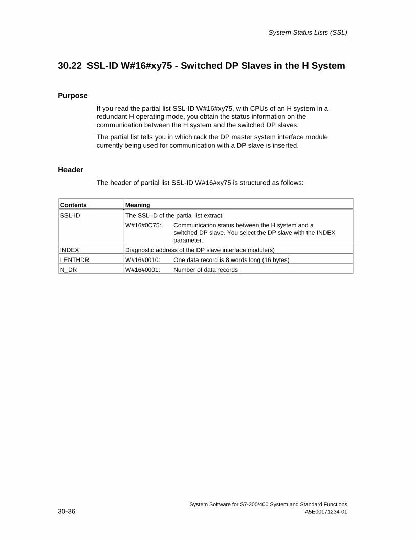
System Status Lists (SSL)
System Software for S7-300/400 System and Standard Functions30-36 A5E00171234-01
30.22 SSL-ID W#16#xy75 - Switched DP Slaves in the H System
Purpose
If you read the partial list SSL-ID W#16#xy75, with CPUs of an H system in aredundant H operating mode, you obtain the status information on thecommunication between the H system and the switched DP slaves.
The partial list tells you in which rack the DP master system interface modulecurrently being used for communication with a DP slave is inserted.
Header
The header of partial list SSL-ID W#16#xy75 is structured as follows:
Contents Meaning
SSL-ID The SSL-ID of the partial list extract
W#16#0C75: Communication status between the H system and aswitched DP slave. You select the DP slave with the INDEX parameter.
INDEX Diagnostic address of the DP slave interface module(s)
LENTHDR W#16#0010: One data record is 8 words long (16 bytes)
N_DR W#16#0001: Number of data records
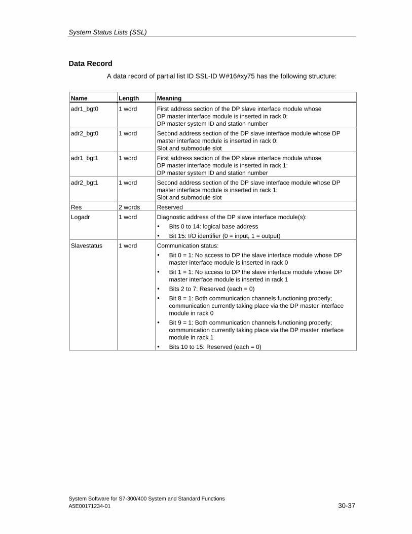
System Status Lists (SSL)
System Software for S7-300/400 System and Standard FunctionsA5E00171234-01 30-37
Data Record
A data record of partial list ID SSL-ID W#16#xy75 has the following structure:
Name Length Meaning
adr1_bgt0 1 word First address section of the DP slave interface module whoseDP master interface module is inserted in rack 0:DP master system ID and station number
adr2_bgt0 1 word Second address section of the DP slave interface module whose DPmaster interface module is inserted in rack 0:Slot and submodule slot
adr1_bgt1 1 word First address section of the DP slave interface module whoseDP master interface module is inserted in rack 1:DP master system ID and station number
adr2_bgt1 1 word Second address section of the DP slave interface module whose DPmaster interface module is inserted in rack 1:Slot and submodule slot
Res 2 words Reserved
Logadr 1 word Diagnostic address of the DP slave interface module(s):
• Bits 0 to 14: logical base address
• Bit 15: I/O identifier (0 = input, 1 = output)
Slavestatus 1 word Communication status:
• Bit 0 = 1: No access to DP the slave interface module whose DPmaster interface module is inserted in rack 0
• Bit 1 = 1: No access to DP the slave interface module whose DPmaster interface module is inserted in rack 1
• Bits 2 to 7: Reserved (each = 0)
• Bit 8 = 1: Both communication channels functioning properly;communication currently taking place via the DP master interfacemodule in rack 0
• Bit 9 = 1: Both communication channels functioning properly;communication currently taking place via the DP master interfacemodule in rack 1
• Bits 10 to 15: Reserved (each = 0)
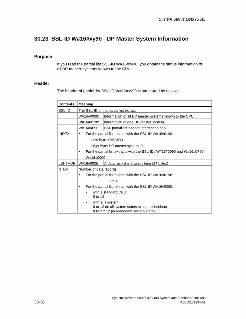
System Status Lists (SSL)
System Software for S7-300/400 System and Standard Functions30-38 A5E00171234-01
30.23 SSL-ID W#16#xy90 - DP Master System Information
Purpose
If you read the partial list SSL-ID W#16#xy90, you obtain the status information ofall DP master systems known to the CPU.
Header
The header of partial list SSL-ID W#16#xy90 is structured as follows:
Contents Meaning
SSL-ID The SSL-ID of the partial list extract
W#16#0090: Information of all DP master systems known to the CPU
W#16#0190: Information of one DP master system
W#16#0F90: SSL partial list header information only
INDEX • For the partial list extract with the SSL-ID W#16#0190:
Low Byte: B#16#00
High Byte: DP master system ID
• For the partial list extracts with the SSL-IDs W#16#0090 and W#16#0F90:
W#16#0000
LENTHDR W#16#000E: A data record is 7 words long (14 bytes)
N_DR Number of data records
• For the partial list extract with the SSL-ID W#16#0190:
0 to 1
• For the partial list extract with the SSL-ID W#16#0090:
- with a standard CPU:0 to 14
- with a H system:0 to 12 (in all system states except redundant)0 to 2 x 12 (in redundant system state)
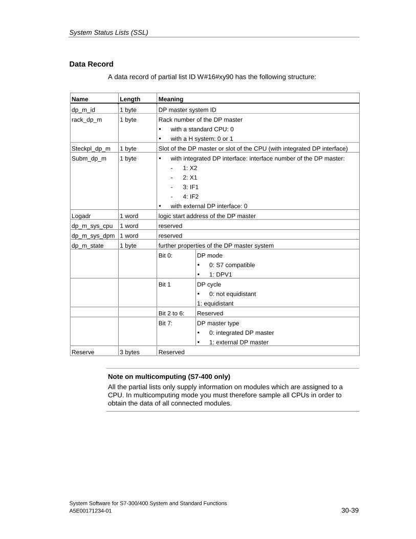
System Status Lists (SSL)
System Software for S7-300/400 System and Standard FunctionsA5E00171234-01 30-39
Data Record
A data record of partial list ID W#16#xy90 has the following structure:
Name Length Meaning
dp_m_id 1 byte DP master system ID
rack_dp_m 1 byte Rack number of the DP master
• with a standard CPU: 0
• with a H system: 0 or 1
Steckpl_dp_m 1 byte Slot of the DP master or slot of the CPU (with integrated DP interface)
Subm_dp_m 1 byte • with integrated DP interface: interface number of the DP master:
- 1: X2
- 2: X1
- 3: IF1
- 4: IF2
• with external DP interface: 0
Logadr 1 word logic start address of the DP master
dp_m_sys_cpu 1 word reserved
dp_m_sys_dpm 1 word reserved
dp_m_state 1 byte further properties of the DP master system
Bit 0: DP mode
• 0: S7 compatible
• 1: DPV1
Bit 1 DP cycle
• 0: not equidistant
1: equidistant
Bit 2 to 6: Reserved
Bit 7: DP master type
• 0: integrated DP master
• 1: external DP master
Reserve 3 bytes Reserved
Note on multicomputing (S7-400 only)
All the partial lists only supply information on modules which are assigned to aCPU. In multicomputing mode you must therefore sample all CPUs in order toobtain the data of all connected modules.
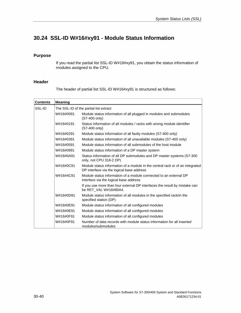
System Status Lists (SSL)
System Software for S7-300/400 System and Standard Functions30-40 A5E00171234-01
30.24 SSL-ID W#16#xy91 - Module Status Information
Purpose
If you read the partial list SSL-ID W#16#xy91, you obtain the status information ofmodules assigned to the CPU.
Header
The header of partial list SSL-ID W#16#xy91 is structured as follows:
Contents Meaning
SSL-ID The SSL-ID of the partial list extract
W#16#0091 Module status information of all plugged in modules and submodules(S7-400 only)
W#16#0191 Status information of all modules / racks with wrong module identifier(S7-400 only)
W#16#0291 Module status information of all faulty modules (S7-400 only)
W#16#0391 Module status information of all unavailable modules (S7-400 only)
W#16#0591 Module status information of all submodules of the host module
W#16#0991 Module status information of a DP master system
W#16#0A91 Status information of all DP submodules and DP master systems (S7-300only, not CPU 318-2 DP)
W#16#0C91 Module status information of a module in the central rack or of an integratedDP interface via the logical base address
W#16#4C91 Module status information of a module connected to an external DPinterface via the logical base address
If you use more than four external DP interfaces the result by mistake canbe RET_VAL W#16#80A4.
W#16#0D91 Module status information of all modules in the specified rack/in thespecified station (DP)
W#16#0E91 Module status information of all configured modules
W#16#0E91 Module status information of all configured modules
W#16#0F91 Module status information of all configured modules
W#16#0F91 Number of data records with module status information for all insertedmodules/submodules
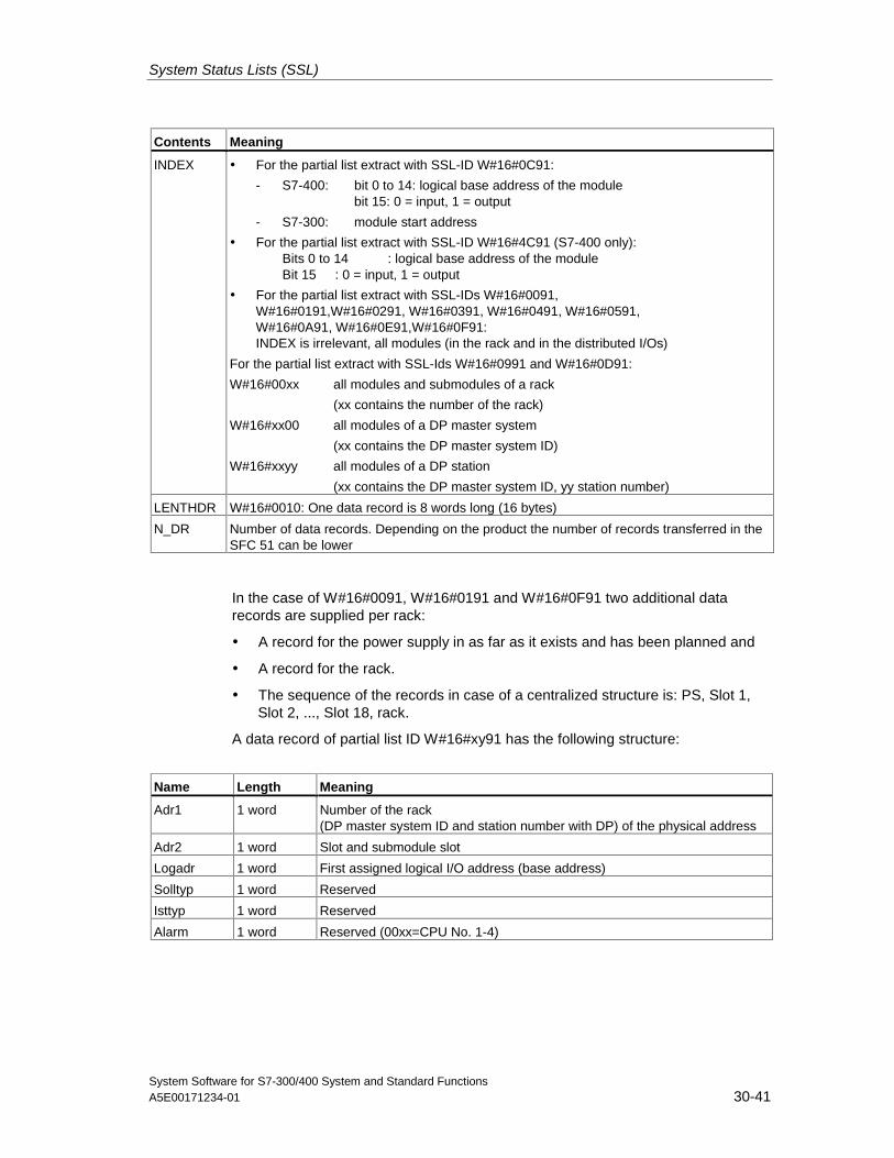
System Status Lists (SSL)
System Software for S7-300/400 System and Standard FunctionsA5E00171234-01 30-41
Contents Meaning
INDEX • For the partial list extract with SSL-ID W#16#0C91:
- S7-400: bit 0 to 14: logical base address of the modulebit 15: 0 = input, 1 = output
- S7-300: module start address
• For the partial list extract with SSL-ID W#16#4C91 (S7-400 only):Bits 0 to 14 : logical base address of the moduleBit 15 : 0 = input, 1 = output
• For the partial list extract with SSL-IDs W#16#0091,W#16#0191,W#16#0291, W#16#0391, W#16#0491, W#16#0591,W#16#0A91, W#16#0E91,W#16#0F91:INDEX is irrelevant, all modules (in the rack and in the distributed I/Os)
For the partial list extract with SSL-Ids W#16#0991 and W#16#0D91:
W#16#00xx all modules and submodules of a rack
(xx contains the number of the rack)
W#16#xx00 all modules of a DP master system
(xx contains the DP master system ID)
W#16#xxyy all modules of a DP station
(xx contains the DP master system ID, yy station number)
LENTHDR W#16#0010: One data record is 8 words long (16 bytes)
N_DR Number of data records. Depending on the product the number of records transferred in theSFC 51 can be lower
In the case of W#16#0091, W#16#0191 and W#16#0F91 two additional datarecords are supplied per rack:
• A record for the power supply in as far as it exists and has been planned and
• A record for the rack.
• The sequence of the records in case of a centralized structure is: PS, Slot 1,Slot 2, ..., Slot 18, rack.
A data record of partial list ID W#16#xy91 has the following structure:
Name Length Meaning
Adr1 1 word Number of the rack(DP master system ID and station number with DP) of the physical address
Adr2 1 word Slot and submodule slot
Logadr 1 word First assigned logical I/O address (base address)
Solltyp 1 word Reserved
Isttyp 1 word Reserved
Alarm 1 word Reserved (00xx=CPU No. 1-4)
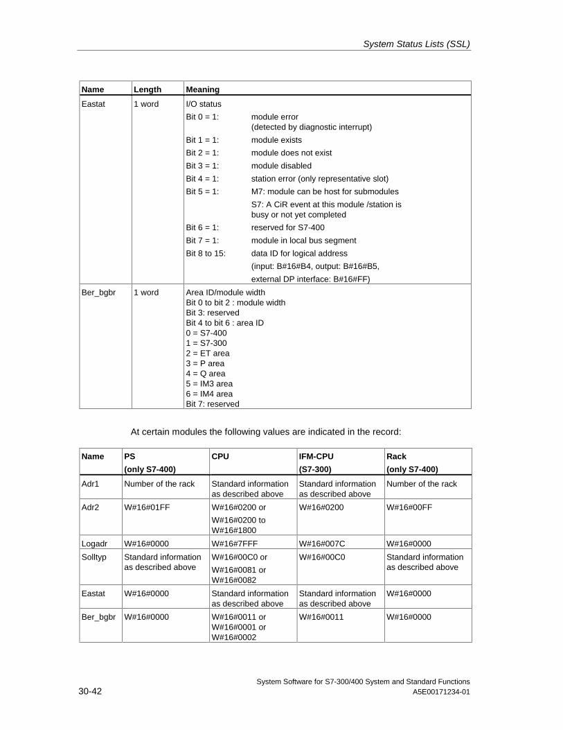
System Status Lists (SSL)
System Software for S7-300/400 System and Standard Functions30-42 A5E00171234-01
Name Length Meaning
Eastat 1 word I/O status
Bit 0 = 1: module error(detected by diagnostic interrupt)
Bit 1 = 1: module exists
Bit 2 = 1: module does not exist
Bit 3 = 1: module disabled
Bit 4 = 1: station error (only representative slot)
Bit 5 = 1: M7: module can be host for submodules
S7: A CiR event at this module /station isbusy or not yet completed
Bit 6 = 1: reserved for S7-400
Bit 7 = 1: module in local bus segment
Bit 8 to 15: data ID for logical address
(input: B#16#B4, output: B#16#B5,
external DP interface: B#16#FF)
Ber_bgbr 1 word Area ID/module widthBit 0 to bit 2 : module widthBit 3: reservedBit 4 to bit 6 : area ID0 = S7-4001 = S7-3002 = ET area3 = P area4 = Q area5 = IM3 area6 = IM4 areaBit 7: reserved
At certain modules the following values are indicated in the record:
Name PS
(only S7-400)
CPU IFM-CPU
(S7-300)
Rack
(only S7-400)
Adr1 Number of the rack Standard informationas described above
Standard informationas described above
Number of the rack
Adr2 W#16#01FF W#16#0200 or
W#16#0200 toW#16#1800
W#16#0200 W#16#00FF
Logadr W#16#0000 W#16#7FFF W#16#007C W#16#0000
Solltyp Standard informationas described above
W#16#00C0 or
W#16#0081 orW#16#0082
W#16#00C0 Standard informationas described above
Eastat W#16#0000 Standard informationas described above
Standard informationas described above
W#16#0000
Ber_bgbr W#16#0000 W#16#0011 orW#16#0001 orW#16#0002
W#16#0011 W#16#0000

System Status Lists (SSL)
System Software for S7-300/400 System and Standard FunctionsA5E00171234-01 30-43
adr1
The parameter adr1 contains the following:
• when installed centrally, the rack number.
0123456789101112131415
Rack number0
Bits of the parameter adr1 when installed centrally
• with a distributed configuration
the DP master system ID
the station number.
0123456789101112131415
Station numberDP master system ID
Bits of the parameter adr1 in a distributed configuration.
adr2
The parameter adr2 contains the slot and submodule slot.
0123456789101112131415
Submodule slotSlot
Bits of the parameter adr2.
Information on Multicomputing (only S7-400)
All the partial lists only supply information on the modules which are assigned to aCPU. In multicomputing mode you must therefore sample all the CPUs in order toobtain the data of all the connected modules.
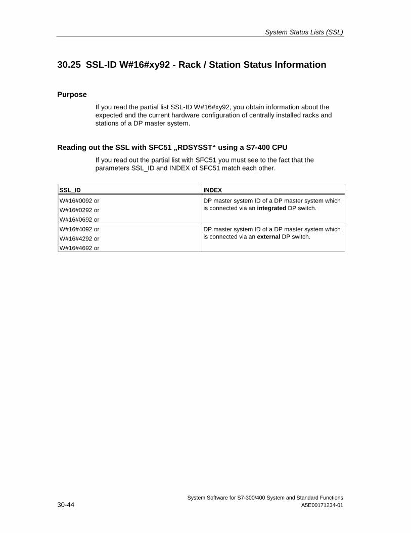
System Status Lists (SSL)
System Software for S7-300/400 System and Standard Functions30-44 A5E00171234-01
30.25 SSL-ID W#16#xy92 - Rack / Station Status Information
Purpose
If you read the partial list SSL-ID W#16#xy92, you obtain information about theexpected and the current hardware configuration of centrally installed racks andstations of a DP master system.
Reading out the SSL with SFC51 „RDSYSST“ using a S7-400 CPU
If you read out the partial list with SFC51 you must see to the fact that theparameters SSL_ID and INDEX of SFC51 match each other.
SSL_ID INDEX
W#16#0092 or
W#16#0292 or
W#16#0692 or
DP master system ID of a DP master system whichis connected via an integrated DP switch.
W#16#4092 or
W#16#4292 or
W#16#4692 or
DP master system ID of a DP master system whichis connected via an external DP switch.
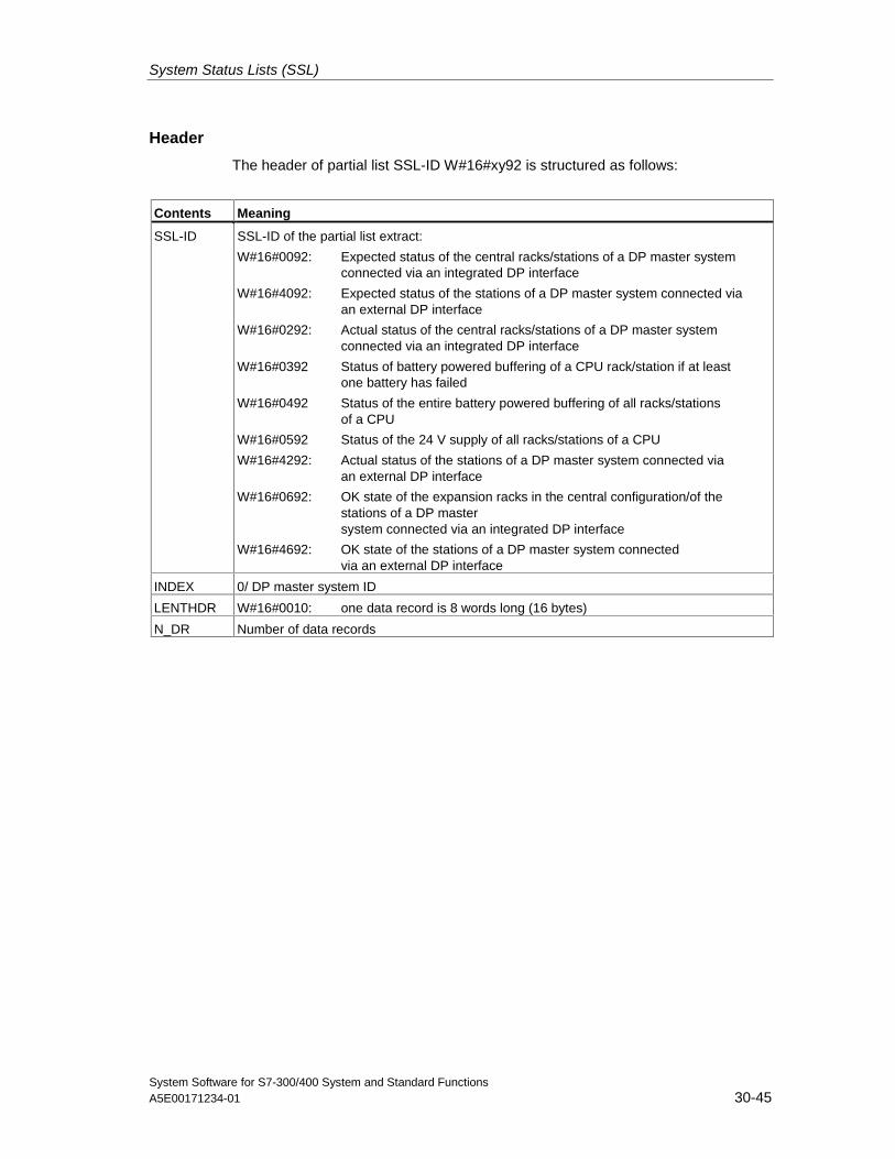
System Status Lists (SSL)
System Software for S7-300/400 System and Standard FunctionsA5E00171234-01 30-45
Header
The header of partial list SSL-ID W#16#xy92 is structured as follows:
Contents Meaning
SSL-ID SSL-ID of the partial list extract:
W#16#0092: Expected status of the central racks/stations of a DP master systemconnected via an integrated DP interface
W#16#4092: Expected status of the stations of a DP master system connected viaan external DP interface
W#16#0292: Actual status of the central racks/stations of a DP master systemconnected via an integrated DP interface
W#16#0392 Status of battery powered buffering of a CPU rack/station if at leastone battery has failed
W#16#0492 Status of the entire battery powered buffering of all racks/stationsof a CPU
W#16#0592 Status of the 24 V supply of all racks/stations of a CPU
W#16#4292: Actual status of the stations of a DP master system connected viaan external DP interface
W#16#0692: OK state of the expansion racks in the central configuration/of thestations of a DP mastersystem connected via an integrated DP interface
W#16#4692: OK state of the stations of a DP master system connectedvia an external DP interface
INDEX 0/ DP master system ID
LENTHDR W#16#0010: one data record is 8 words long (16 bytes)
N_DR Number of data records
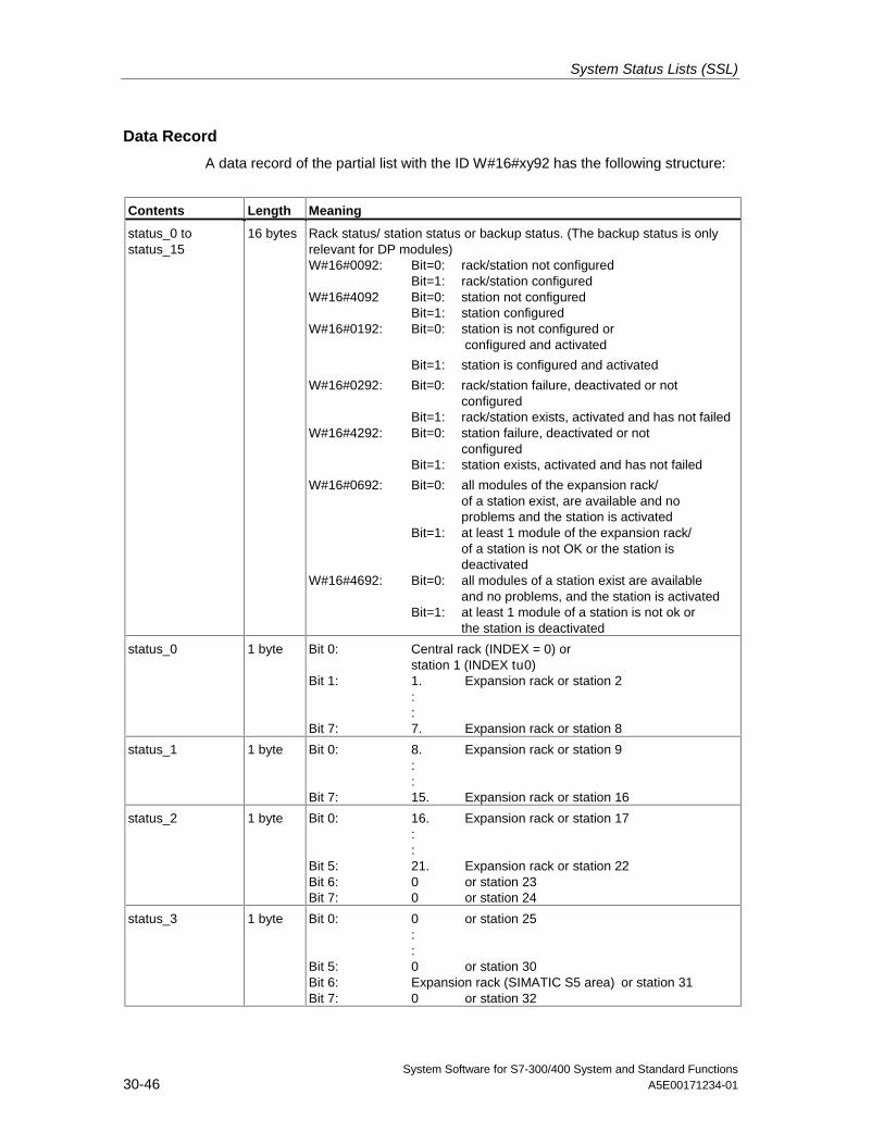
System Status Lists (SSL)
System Software for S7-300/400 System and Standard Functions30-46 A5E00171234-01
Data Record
A data record of the partial list with the ID W#16#xy92 has the following structure:
Contents Length Meaning
status_0 tostatus_15
16 bytes Rack status/ station status or backup status. (The backup status is onlyrelevant for DP modules)W#16#0092: Bit=0: rack/station not configured
Bit=1: rack/station configuredW#16#4092 Bit=0: station not configured
Bit=1: station configuredW#16#0192: Bit=0: station is not configured or
configured and activated
Bit=1: station is configured and activated
W#16#0292: Bit=0: rack/station failure, deactivated or notconfigured
Bit=1: rack/station exists, activated and has not failedW#16#4292: Bit=0: station failure, deactivated or not
configuredBit=1: station exists, activated and has not failed
W#16#0692: Bit=0: all modules of the expansion rack/of a station exist, are available and noproblems and the station is activated
Bit=1: at least 1 module of the expansion rack/of a station is not OK or the station isdeactivated
W#16#4692: Bit=0: all modules of a station exist are availableand no problems, and the station is activated
Bit=1: at least 1 module of a station is not ok orthe station is deactivated
status_0 1 byte Bit 0: Central rack (INDEX = 0) orstation 1 (INDEX tu0)
Bit 1: 1. Expansion rack or station 2::
Bit 7: 7. Expansion rack or station 8
status_1 1 byte Bit 0: 8. Expansion rack or station 9::
Bit 7: 15. Expansion rack or station 16
status_2 1 byte Bit 0: 16. Expansion rack or station 17::
Bit 5: 21. Expansion rack or station 22Bit 6: 0 or station 23Bit 7: 0 or station 24
status_3 1 byte Bit 0: 0 or station 25::
Bit 5: 0 or station 30Bit 6: Expansion rack (SIMATIC S5 area) or station 31Bit 7: 0 or station 32
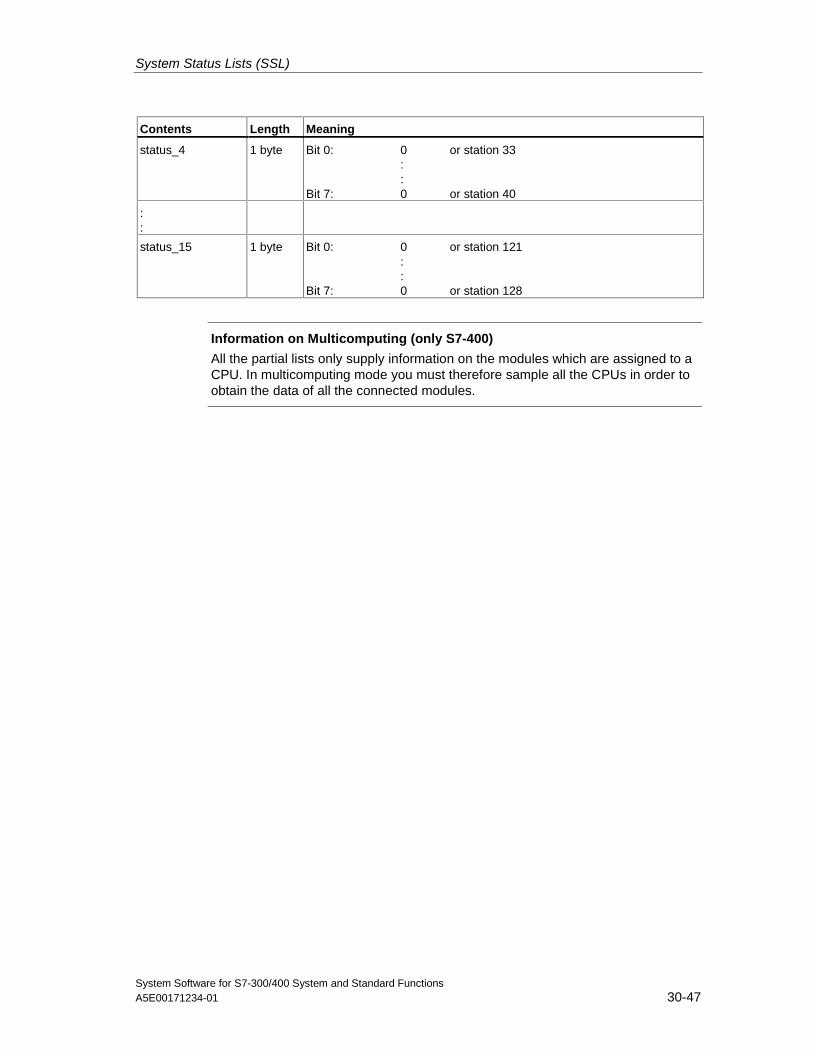
System Status Lists (SSL)
System Software for S7-300/400 System and Standard FunctionsA5E00171234-01 30-47
Contents Length Meaning
status_4 1 byte Bit 0: 0 or station 33::
Bit 7: 0 or station 40
::
status_15 1 byte Bit 0: 0 or station 121::
Bit 7: 0 or station 128
Information on Multicomputing (only S7-400)
All the partial lists only supply information on the modules which are assigned to aCPU. In multicomputing mode you must therefore sample all the CPUs in order toobtain the data of all the connected modules.
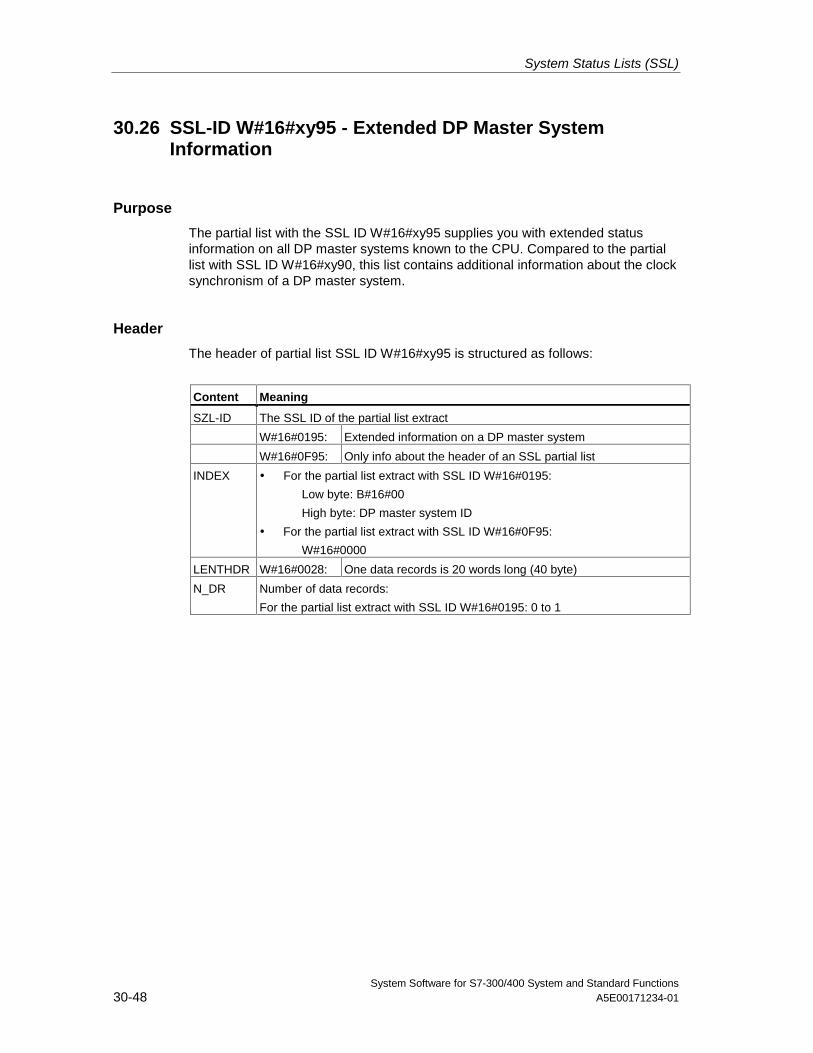
System Status Lists (SSL)
System Software for S7-300/400 System and Standard Functions30-48 A5E00171234-01
30.26 SSL-ID W#16#xy95 - Extended DP Master SystemInformation
Purpose
The partial list with the SSL ID W#16#xy95 supplies you with extended statusinformation on all DP master systems known to the CPU. Compared to the partiallist with SSL ID W#16#xy90, this list contains additional information about the clocksynchronism of a DP master system.
Header
The header of partial list SSL ID W#16#xy95 is structured as follows:
Content Meaning
SZL-ID The SSL ID of the partial list extract
W#16#0195: Extended information on a DP master system
W#16#0F95: Only info about the header of an SSL partial list
INDEX • For the partial list extract with SSL ID W#16#0195:
Low byte: B#16#00
High byte: DP master system ID
• For the partial list extract with SSL ID W#16#0F95:
W#16#0000
LENTHDR W#16#0028: One data records is 20 words long (40 byte)
N_DR Number of data records:
For the partial list extract with SSL ID W#16#0195: 0 to 1
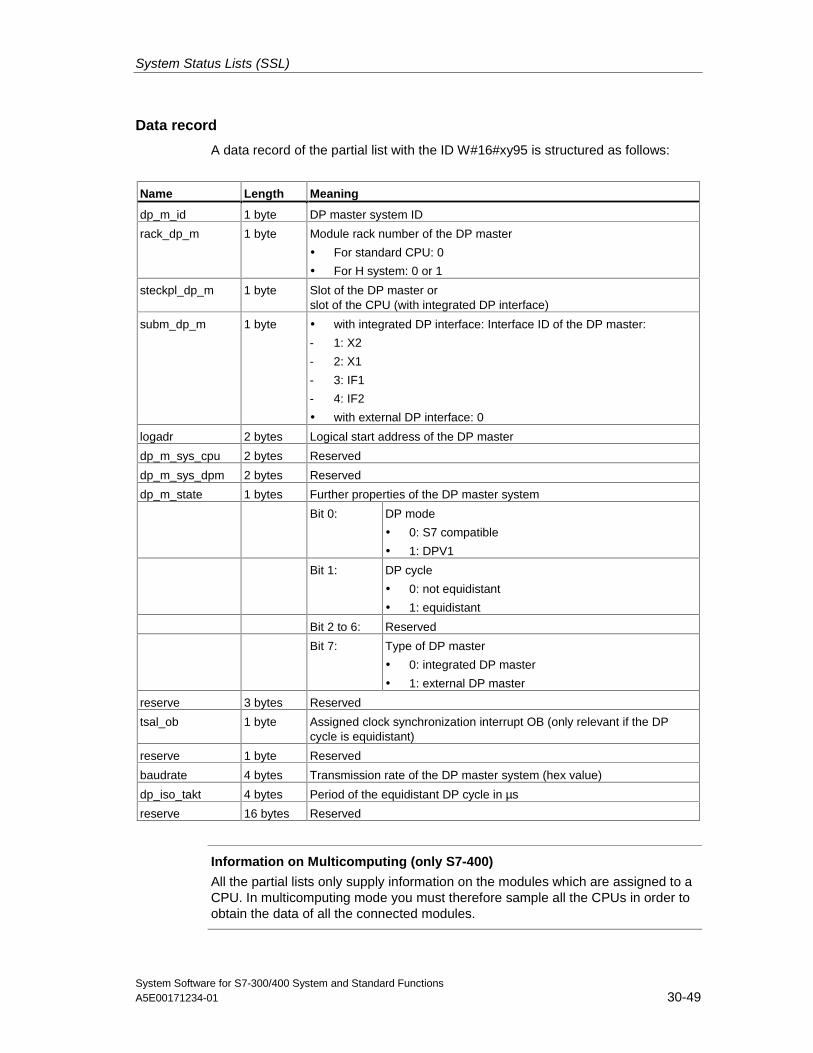
System Status Lists (SSL)
System Software for S7-300/400 System and Standard FunctionsA5E00171234-01 30-49
Data record
A data record of the partial list with the ID W#16#xy95 is structured as follows:
Name Length Meaning
dp_m_id 1 byte DP master system ID
rack_dp_m 1 byte Module rack number of the DP master
• For standard CPU: 0
• For H system: 0 or 1
steckpl_dp_m 1 byte Slot of the DP master orslot of the CPU (with integrated DP interface)
subm_dp_m 1 byte • with integrated DP interface: Interface ID of the DP master:
- 1: X2
- 2: X1
- 3: IF1
- 4: IF2
• with external DP interface: 0
logadr 2 bytes Logical start address of the DP master
dp_m_sys_cpu 2 bytes Reserved
dp_m_sys_dpm 2 bytes Reserved
dp_m_state 1 bytes Further properties of the DP master system
Bit 0: DP mode
• 0: S7 compatible
• 1: DPV1
Bit 1: DP cycle
• 0: not equidistant
• 1: equidistant
Bit 2 to 6: Reserved
Bit 7: Type of DP master
• 0: integrated DP master
• 1: external DP master
reserve 3 bytes Reserved
tsal_ob 1 byte Assigned clock synchronization interrupt OB (only relevant if the DPcycle is equidistant)
reserve 1 byte Reserved
baudrate 4 bytes Transmission rate of the DP master system (hex value)
dp_iso_takt 4 bytes Period of the equidistant DP cycle in µs
reserve 16 bytes Reserved
Information on Multicomputing (only S7-400)
All the partial lists only supply information on the modules which are assigned to aCPU. In multicomputing mode you must therefore sample all the CPUs in order toobtain the data of all the connected modules.
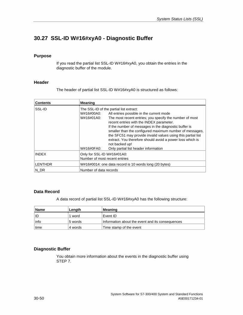
System Status Lists (SSL)
System Software for S7-300/400 System and Standard Functions30-50 A5E00171234-01
30.27 SSL-ID W#16#xyA0 - Diagnostic Buffer
Purpose
If you read the partial list SSL-ID W#16#xyA0, you obtain the entries in thediagnostic buffer of the module.
Header
The header of partial list SSL-ID W#16#xyA0 is structured as follows:
Contents Meaning
SSL-ID The SSL-ID of the partial list extract:W#16#00A0: All entries possible in the current modeW#16#01A0: The most recent entries; you specify the number of most
recent entries with the INDEX parameter.If the number of messages in the diagnostic buffer issmaller than the configured maximum number of messages,the SFC51 may provide invalid values using this partial listextract. You therefore should avoid a power loss which isnot backed up!
W#16#0FA0: Only partial list header information
INDEX Only for SSL-ID W#16#01A0:Number of most recent entries
LENTHDR W#16#0014: one data record is 10 words long (20 bytes)
N_DR Number of data records
Data Record
A data record of partial list SSL-ID W#16#xyA0 has the following structure:
Name Length Meaning
ID 1 word Event ID
info 5 words Information about the event and its consequences
time 4 words Time stamp of the event
Diagnostic Buffer
You obtain more information about the events in the diagnostic buffer usingSTEP 7.
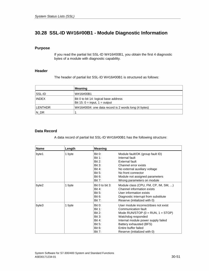
System Status Lists (SSL)
System Software for S7-300/400 System and Standard FunctionsA5E00171234-01 30-51
30.28 SSL-ID W#16#00B1 - Module Diagnostic Information
Purpose
If you read the partial list SSL-ID W#16#00B1, you obtain the first 4 diagnosticbytes of a module with diagnostic capability.
Header
The header of partial list SSL-ID W#16#00B1 is structured as follows:
Meaning
SSL-ID W#16#00B1
INDEX Bit 0 to bit 14: logical base addressBit 15: 0 = input, 1 = output
LENTHDR W#16#0004: one data record is 2 words long (4 bytes)
N_DR 1
Data Record
A data record of partial list SSL-ID W#16#00B1 has the following structure:
Name Length Meaning
byte1 1 byte Bit 0: Module fault/OK (group fault ID)Bit 1: Internal faultBit 2: External faultBit 3: Channel error existsBit 4: No external auxiliary voltageBit 5: No front connectorBit 6: Module not assigned parametersBit 7: Wrong parameters on module
byte2 1 byte Bit 0 to bit 3: Module class (CPU, FM, CP, IM, SM, ...)Bit 4: Channel information existsBit 5: User information existsBit 6: Diagnostic interrupt from substituteBit 7: Reserve (initialized with 0)
byte3 1 byte Bit 0: User module incorrect/does not existBit 1: Communication faultBit 2: Mode RUN/STOP (0 = RUN, 1 = STOP)Bit 3: Watchdog respondedBit 4: Internal module power supply failedBit 5: Battery exhausted (BFS)Bit 6: Entire buffer failedBit 7: Reserve (initialized with 0)
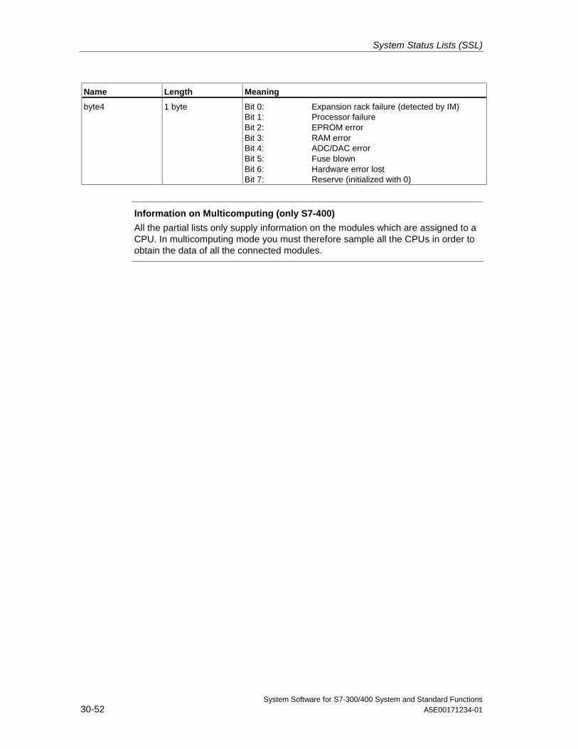
System Status Lists (SSL)
System Software for S7-300/400 System and Standard Functions30-52 A5E00171234-01
Name Length Meaning
byte4 1 byte Bit 0: Expansion rack failure (detected by IM)Bit 1: Processor failureBit 2: EPROM errorBit 3: RAM errorBit 4: ADC/DAC errorBit 5: Fuse blownBit 6: Hardware error lostBit 7: Reserve (initialized with 0)
Information on Multicomputing (only S7-400)
All the partial lists only supply information on the modules which are assigned to aCPU. In multicomputing mode you must therefore sample all the CPUs in order toobtain the data of all the connected modules.
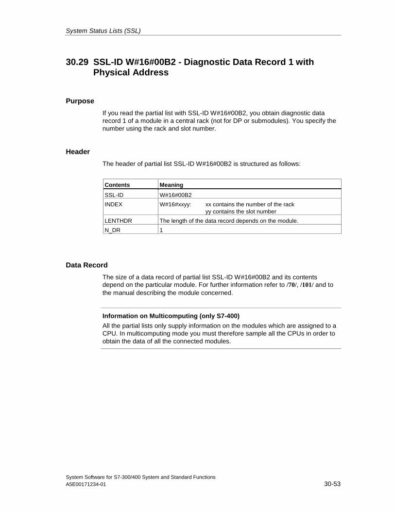
System Status Lists (SSL)
System Software for S7-300/400 System and Standard FunctionsA5E00171234-01 30-53
30.29 SSL-ID W#16#00B2 - Diagnostic Data Record 1 withPhysical Address
Purpose
If you read the partial list with SSL-ID W#16#00B2, you obtain diagnostic datarecord 1 of a module in a central rack (not for DP or submodules). You specify thenumber using the rack and slot number.
Header
The header of partial list SSL-ID W#16#00B2 is structured as follows:
Contents Meaning
SSL-ID W#16#00B2
INDEX W#16#xxyy: xx contains the number of the rackyy contains the slot number
LENTHDR The length of the data record depends on the module.
N_DR 1
Data Record
The size of a data record of partial list SSL-ID W#16#00B2 and its contentsdepend on the particular module. For further information refer to /70/, /101/ and tothe manual describing the module concerned.
Information on Multicomputing (only S7-400)
All the partial lists only supply information on the modules which are assigned to aCPU. In multicomputing mode you must therefore sample all the CPUs in order toobtain the data of all the connected modules.
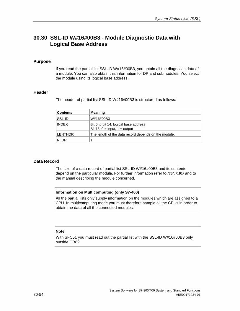
System Status Lists (SSL)
System Software for S7-300/400 System and Standard Functions30-54 A5E00171234-01
30.30 SSL-ID W#16#00B3 - Module Diagnostic Data withLogical Base Address
Purpose
If you read the partial list SSL-ID W#16#00B3, you obtain all the diagnostic data ofa module. You can also obtain this information for DP and submodules. You selectthe module using its logical base address.
Header
The header of partial list SSL-ID W#16#00B3 is structured as follows:
Contents Meaning
SSL-ID W#16#00B3
INDEX Bit 0 to bit 14: logical base addressBit 15: 0 = input, 1 = output
LENTHDR The length of the data record depends on the module.
N_DR 1
Data Record
The size of a data record of partial list SSL-ID W#16#00B3 and its contentsdepend on the particular module. For further information refer to /70/, /101/ and tothe manual describing the module concerned.
Information on Multicomputing (only S7-400)
All the partial lists only supply information on the modules which are assigned to aCPU. In multicomputing mode you must therefore sample all the CPUs in order toobtain the data of all the connected modules.
Note
With SFC51 you must read out the partial list with the SSL-ID W#16#00B3 onlyoutside OB82.
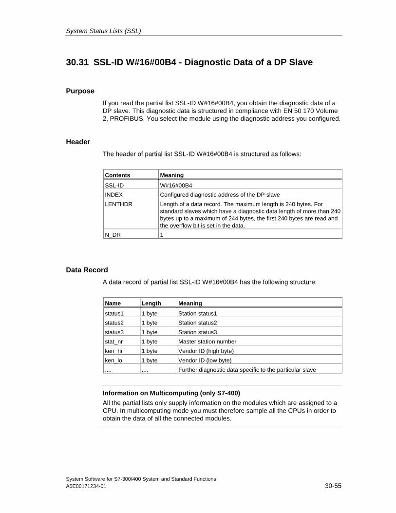
System Status Lists (SSL)
System Software for S7-300/400 System and Standard FunctionsA5E00171234-01 30-55
30.31 SSL-ID W#16#00B4 - Diagnostic Data of a DP Slave
Purpose
If you read the partial list SSL-ID W#16#00B4, you obtain the diagnostic data of aDP slave. This diagnostic data is structured in compliance with EN 50 170 Volume2, PROFIBUS. You select the module using the diagnostic address you configured.
Header
The header of partial list SSL-ID W#16#00B4 is structured as follows:
Contents Meaning
SSL-ID W#16#00B4
INDEX Configured diagnostic address of the DP slave
LENTHDR Length of a data record. The maximum length is 240 bytes. Forstandard slaves which have a diagnostic data length of more than 240bytes up to a maximum of 244 bytes, the first 240 bytes are read andthe overflow bit is set in the data.
N_DR 1
Data Record
A data record of partial list SSL-ID W#16#00B4 has the following structure:
Name Length Meaning
status1 1 byte Station status1
status2 1 byte Station status2
status3 1 byte Station status3
stat_nr 1 byte Master station number
ken_hi 1 byte Vendor ID (high byte)
ken_lo 1 byte Vendor ID (low byte)
.... .... Further diagnostic data specific to the particular slave
Information on Multicomputing (only S7-400)
All the partial lists only supply information on the modules which are assigned to aCPU. In multicomputing mode you must therefore sample all the CPUs in order toobtain the data of all the connected modules.

System Status Lists (SSL)
System Software for S7-300/400 System and Standard Functions30-56 A5E00171234-01
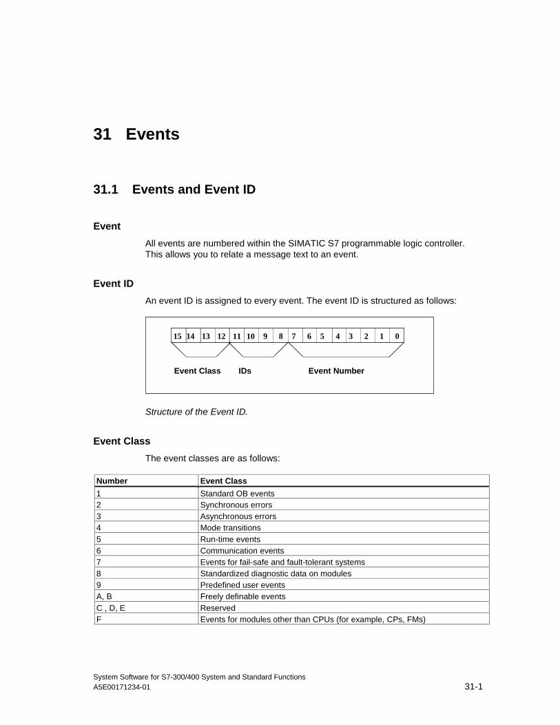
System Software for S7-300/400 System and Standard FunctionsA5E00171234-01 31-1
31 Events
31.1 Events and Event ID
Event
All events are numbered within the SIMATIC S7 programmable logic controller.This allows you to relate a message text to an event.
Event ID
An event ID is assigned to every event. The event ID is structured as follows:
1214 1315 810 911 46 57 02 13
Event Class IDs Event Number
Structure of the Event ID.
Event Class
The event classes are as follows:
Number Event Class
1 Standard OB events2 Synchronous errors3 Asynchronous errors4 Mode transitions5 Run-time events6 Communication events7 Events for fail-safe and fault-tolerant systems8 Standardized diagnostic data on modules9 Predefined user eventsA, B Freely definable eventsC , D, E ReservedF Events for modules other than CPUs (for example, CPs, FMs)
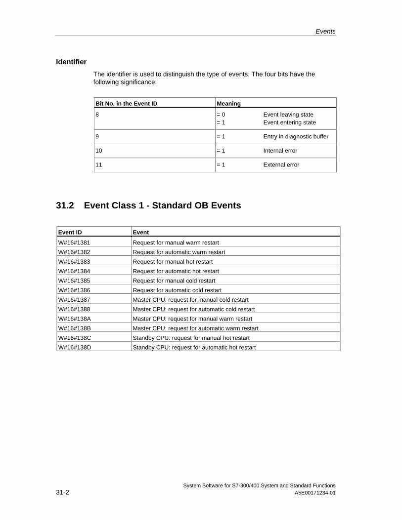
Events
System Software for S7-300/400 System and Standard Functions31-2 A5E00171234-01
Identifier
The identifier is used to distinguish the type of events. The four bits have thefollowing significance:
Bit No. in the Event ID Meaning
8 = 0 Event leaving state= 1 Event entering state
9 = 1 Entry in diagnostic buffer
10 = 1 Internal error
11 = 1 External error
31.2 Event Class 1 - Standard OB Events
Event ID Event
W#16#1381 Request for manual warm restart
W#16#1382 Request for automatic warm restart
W#16#1383 Request for manual hot restart
W#16#1384 Request for automatic hot restart
W#16#1385 Request for manual cold restart
W#16#1386 Request for automatic cold restart
W#16#1387 Master CPU: request for manual cold restart
W#16#1388 Master CPU: request for automatic cold restart
W#16#138A Master CPU: request for manual warm restart
W#16#138B Master CPU: request for automatic warm restart
W#16#138C Standby CPU: request for manual hot restart
W#16#138D Standby CPU: request for automatic hot restart
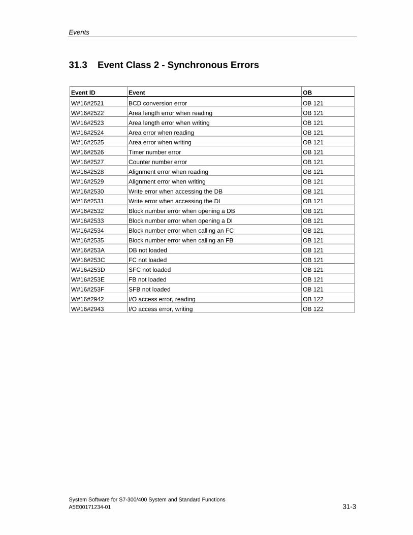
Events
System Software for S7-300/400 System and Standard FunctionsA5E00171234-01 31-3
31.3 Event Class 2 - Synchronous Errors
Event ID Event OB
W#16#2521 BCD conversion error OB 121
W#16#2522 Area length error when reading OB 121
W#16#2523 Area length error when writing OB 121
W#16#2524 Area error when reading OB 121
W#16#2525 Area error when writing OB 121
W#16#2526 Timer number error OB 121
W#16#2527 Counter number error OB 121
W#16#2528 Alignment error when reading OB 121
W#16#2529 Alignment error when writing OB 121
W#16#2530 Write error when accessing the DB OB 121
W#16#2531 Write error when accessing the DI OB 121
W#16#2532 Block number error when opening a DB OB 121
W#16#2533 Block number error when opening a DI OB 121
W#16#2534 Block number error when calling an FC OB 121
W#16#2535 Block number error when calling an FB OB 121
W#16#253A DB not loaded OB 121
W#16#253C FC not loaded OB 121
W#16#253D SFC not loaded OB 121
W#16#253E FB not loaded OB 121
W#16#253F SFB not loaded OB 121
W#16#2942 I/O access error, reading OB 122
W#16#2943 I/O access error, writing OB 122
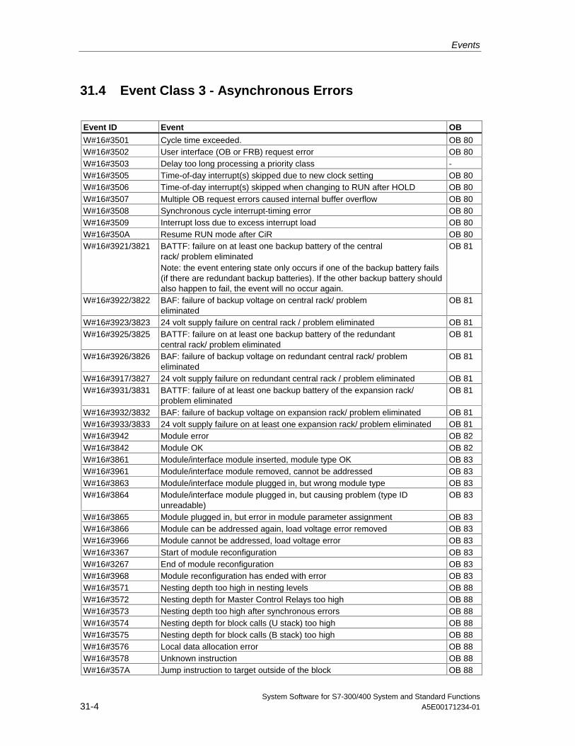
Events
System Software for S7-300/400 System and Standard Functions31-4 A5E00171234-01
31.4 Event Class 3 - Asynchronous Errors
Event ID Event OB
W#16#3501 Cycle time exceeded. OB 80W#16#3502 User interface (OB or FRB) request error OB 80W#16#3503 Delay too long processing a priority class -W#16#3505 Time-of-day interrupt(s) skipped due to new clock setting OB 80W#16#3506 Time-of-day interrupt(s) skipped when changing to RUN after HOLD OB 80W#16#3507 Multiple OB request errors caused internal buffer overflow OB 80W#16#3508 Synchronous cycle interrupt-timing error OB 80W#16#3509 Interrupt loss due to excess interrupt load OB 80W#16#350A Resume RUN mode after CiR OB 80W#16#3921/3821 BATTF: failure on at least one backup battery of the central
rack/ problem eliminatedNote: the event entering state only occurs if one of the backup battery fails(if there are redundant backup batteries). If the other backup battery shouldalso happen to fail, the event will no occur again.
OB 81
W#16#3922/3822 BAF: failure of backup voltage on central rack/ problemeliminated
OB 81
W#16#3923/3823 24 volt supply failure on central rack / problem eliminated OB 81W#16#3925/3825 BATTF: failure on at least one backup battery of the redundant
central rack/ problem eliminatedOB 81
W#16#3926/3826 BAF: failure of backup voltage on redundant central rack/ problemeliminated
OB 81
W#16#3917/3827 24 volt supply failure on redundant central rack / problem eliminated OB 81W#16#3931/3831 BATTF: failure of at least one backup battery of the expansion rack/
problem eliminatedOB 81
W#16#3932/3832 BAF: failure of backup voltage on expansion rack/ problem eliminated OB 81W#16#3933/3833 24 volt supply failure on at least one expansion rack/ problem eliminated OB 81W#16#3942 Module error OB 82W#16#3842 Module OK OB 82W#16#3861 Module/interface module inserted, module type OK OB 83W#16#3961 Module/interface module removed, cannot be addressed OB 83W#16#3863 Module/interface module plugged in, but wrong module type OB 83W#16#3864 Module/interface module plugged in, but causing problem (type ID
unreadable)OB 83
W#16#3865 Module plugged in, but error in module parameter assignment OB 83W#16#3866 Module can be addressed again, load voltage error removed OB 83W#16#3966 Module cannot be addressed, load voltage error OB 83W#16#3367 Start of module reconfiguration OB 83W#16#3267 End of module reconfiguration OB 83W#16#3968 Module reconfiguration has ended with error OB 83W#16#3571 Nesting depth too high in nesting levels OB 88W#16#3572 Nesting depth for Master Control Relays too high OB 88W#16#3573 Nesting depth too high after synchronous errors OB 88W#16#3574 Nesting depth for block calls (U stack) too high OB 88W#16#3575 Nesting depth for block calls (B stack) too high OB 88W#16#3576 Local data allocation error OB 88W#16#3578 Unknown instruction OB 88W#16#357A Jump instruction to target outside of the block OB 88
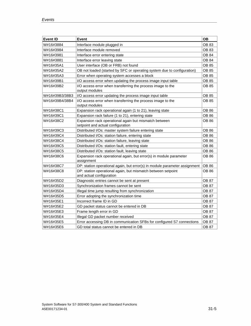
Events
System Software for S7-300/400 System and Standard FunctionsA5E00171234-01 31-5
Event ID Event OB
W#16#3884 Interface module plugged in OB 83W#16#3984 Interface module removed OB 83W#16#3981 Interface error entering state OB 84W#16#3881 Interface error leaving state OB 84W#16#35A1 User interface (OB or FRB) not found OB 85W#16#35A2 OB not loaded (started by SFC or operating system due to configuration) OB 85W#16#35A3 Error when operating system accesses a block OB 85W#16#39B1 I/O access error when updating the process image input table OB 85W#16#39B2 I/O access error when transferring the process image to the
output modulesOB 85
W#16#39B3/38B3 I/O access error updating the process image input table OB 85W#16#39B4/38B4 I/O access error when transferring the process image to the
output modulesOB 85
W#16#38C1 Expansion rack operational again (1 to 21), leaving state OB 86W#16#39C1 Expansion rack failure (1 to 21), entering state OB 86W#16#38C2 Expansion rack operational again but mismatch between
setpoint and actual configurationOB 86
W#16#39C3 Distributed I/Os: master system failure entering state OB 86W#16#39C4 Distributed I/Os: station failure, entering state OB 86W#16#38C4 Distributed I/Os: station failure, leaving state OB 86W#16#39C5 Distributed I/Os: station fault, entering state OB 86W#16#38C5 Distributed I/Os: station fault, leaving state OB 86W#16#38C6 Expansion rack operational again, but error(s) in module parameter
assignmentOB 86
W#16#38C7 DP: station operational again, but error(s) in module parameter assignment OB 86W#16#38C8 DP: station operational again, but mismatch between setpoint
and actual configurationOB 86
W#16#35D2 Diagnostic entries cannot be sent at present OB 87W#16#35D3 Synchronization frames cannot be sent OB 87W#16#35D4 Illegal time jump resulting from synchronization OB 87W#16#35D5 Error adopting the synchronization time OB 87W#16#35E1 Incorrect frame ID in GD OB 87W#16#35E2 GD packet status cannot be entered in DB OB 87W#16#35E3 Frame length error in GD OB 87W#16#35E4 Illegal GD packet number received OB 87W#16#35E5 Error accessing DB in communication SFBs for configured S7 connections OB 87W#16#35E6 GD total status cannot be entered in DB OB 87
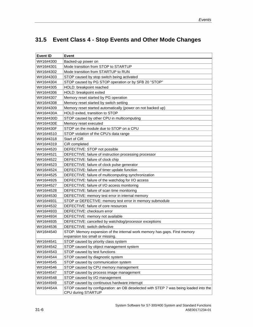
Events
System Software for S7-300/400 System and Standard Functions31-6 A5E00171234-01
31.5 Event Class 4 - Stop Events and Other Mode Changes
Event ID Event
W#16#4300 Backed-up power onW#16#4301 Mode transition from STOP to STARTUPW#16#4302 Mode transition from STARTUP to RUNW#16#4303 STOP caused by stop switch being activatedW#16#4304 STOP caused by PG STOP operation or by SFB 20 "STOP"W#16#4305 HOLD: breakpoint reachedW#16#4306 HOLD: breakpoint exitedW#16#4307 Memory reset started by PG operationW#16#4308 Memory reset started by switch settingW#16#4309 Memory reset started automatically (power on not backed up)W#16#430A HOLD exited, transition to STOPW#16#430D STOP caused by other CPU in multicomputingW#16#430E Memory reset executedW#16#430F STOP on the module due to STOP on a CPUW#16#4510 STOP violation of the CPU's data rangeW#16#4318 Start of CiRW#16#4319 CiR completedW#16#4520 DEFECTIVE: STOP not possibleW#16#4521 DEFECTIVE: failure of instruction processing processorW#16#4522 DEFECTIVE: failure of clock chipW#16#4523 DEFECTIVE: failure of clock pulse generatorW#16#4524 DEFECTIVE: failure of timer update functionW#16#4525 DEFECTIVE: failure of multicomputing synchronizationW#16#4926 DEFECTIVE: failure of the watchdog for I/O accessW#16#4527 DEFECTIVE: failure of I/O access monitoringW#16#4528 DEFECTIVE: failure of scan time monitoringW#16#4530 DEFECTIVE: memory test error in internal memoryW#16#4931 STOP or DEFECTIVE: memory test error in memory submoduleW#16#4532 DEFECTIVE: failure of core resourcesW#16#4933 DEFECTIVE: checksum errorW#16#4934 DEFECTIVE: memory not availableW#16#4935 DEFECTIVE: cancelled by watchdog/processor exceptionsW#16#4536 DEFECTIVE: switch defectiveW#16#4540 STOP: Memory expansion of the internal work memory has gaps. First memory
expansion too small or missing.W#16#4541 STOP caused by priority class systemW#16#4542 STOP caused by object management systemW#16#4543 STOP caused by test functionsW#16#4544 STOP caused by diagnostic systemW#16#4545 STOP caused by communication systemW#16#4546 STOP caused by CPU memory managementW#16#4547 STOP caused by process image managementW#16#4548 STOP caused by I/O managementW#16#4949 STOP caused by continuous hardware interruptW#16#454A STOP caused by configuration: an OB deselected with STEP 7 was being loaded into the
CPU during STARTUP
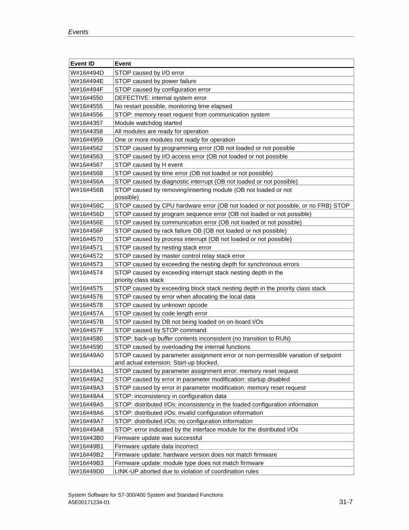
Events
System Software for S7-300/400 System and Standard FunctionsA5E00171234-01 31-7
Event ID Event
W#16#494D STOP caused by I/O errorW#16#494E STOP caused by power failureW#16#494F STOP caused by configuration errorW#16#4550 DEFECTIVE: internal system errorW#16#4555 No restart possible, monitoring time elapsedW#16#4556 STOP: memory reset request from communication systemW#16#4357 Module watchdog startedW#16#4358 All modules are ready for operationW#16#4959 One or more modules not ready for operationW#16#4562 STOP caused by programming error (OB not loaded or not possibleW#16#4563 STOP caused by I/O access error (OB not loaded or not possibleW#16#4567 STOP caused by H eventW#16#4568 STOP caused by time error (OB not loaded or not possible)W#16#456A STOP caused by diagnostic interrupt (OB not loaded or not possible)W#16#456B STOP caused by removing/inserting module (OB not loaded or not
possible)W#16#456C STOP caused by CPU hardware error (OB not loaded or not possible, or no FRB) STOPW#16#456D STOP caused by program sequence error (OB not loaded or not possible)W#16#456E STOP caused by communication error (OB not loaded or not possible)W#16#456F STOP caused by rack failure OB (OB not loaded or not possible)W#16#4570 STOP caused by process interrupt (OB not loaded or not possible)W#16#4571 STOP caused by nesting stack errorW#16#4572 STOP caused by master control relay stack errorW#16#4573 STOP caused by exceeding the nesting depth for synchronous errorsW#16#4574 STOP caused by exceeding interrupt stack nesting depth in the
priority class stackW#16#4575 STOP caused by exceeding block stack nesting depth in the priority class stackW#16#4576 STOP caused by error when allocating the local dataW#16#4578 STOP caused by unknown opcodeW#16#457A STOP caused by code length errorW#16#457B STOP caused by DB not being loaded on on-board I/OsW#16#457F STOP caused by STOP commandW#16#4580 STOP: back-up buffer contents inconsistent (no transition to RUN)W#16#4590 STOP caused by overloading the internal functionsW#16#49A0 STOP caused by parameter assignment error or non-permissible variation of setpoint
and actual extension: Start-up blocked.W#16#49A1 STOP caused by parameter assignment error: memory reset requestW#16#49A2 STOP caused by error in parameter modification: startup disabledW#16#49A3 STOP caused by error in parameter modification: memory reset requestW#16#49A4 STOP: inconsistency in configuration dataW#16#49A5 STOP: distributed I/Os: inconsistency in the loaded configuration informationW#16#49A6 STOP: distributed I/Os: invalid configuration informationW#16#49A7 STOP: distributed I/Os: no configuration informationW#16#49A8 STOP: error indicated by the interface module for the distributed I/OsW#16#43B0 Firmware update was successfulW#16#49B1 Firmware update data incorrectW#16#49B2 Firmware update: hardware version does not match firmwareW#16#49B3 Firmware update: module type does not match firmwareW#16#49D0 LINK-UP aborted due to violation of coordination rules
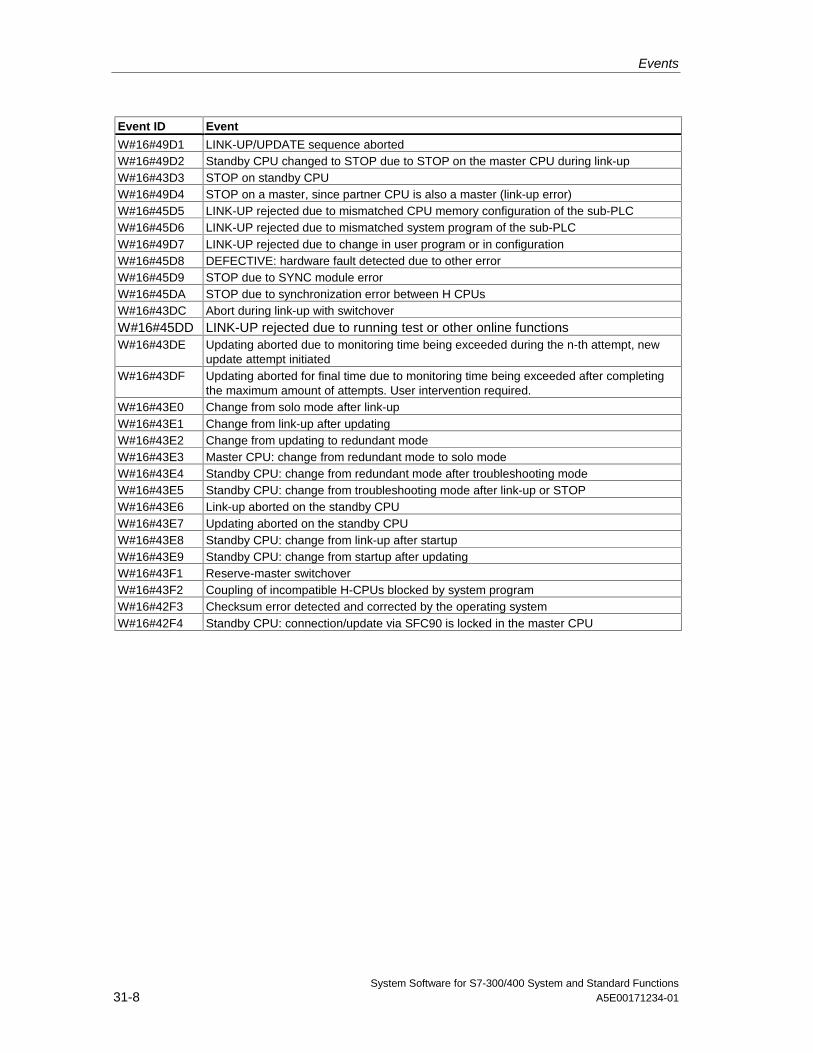
Events
System Software for S7-300/400 System and Standard Functions31-8 A5E00171234-01
Event ID Event
W#16#49D1 LINK-UP/UPDATE sequence abortedW#16#49D2 Standby CPU changed to STOP due to STOP on the master CPU during link-upW#16#43D3 STOP on standby CPUW#16#49D4 STOP on a master, since partner CPU is also a master (link-up error)W#16#45D5 LINK-UP rejected due to mismatched CPU memory configuration of the sub-PLCW#16#45D6 LINK-UP rejected due to mismatched system program of the sub-PLCW#16#49D7 LINK-UP rejected due to change in user program or in configurationW#16#45D8 DEFECTIVE: hardware fault detected due to other errorW#16#45D9 STOP due to SYNC module errorW#16#45DA STOP due to synchronization error between H CPUsW#16#43DC Abort during link-up with switchoverW#16#45DD LINK-UP rejected due to running test or other online functionsW#16#43DE Updating aborted due to monitoring time being exceeded during the n-th attempt, new
update attempt initiatedW#16#43DF Updating aborted for final time due to monitoring time being exceeded after completing
the maximum amount of attempts. User intervention required.W#16#43E0 Change from solo mode after link-upW#16#43E1 Change from link-up after updatingW#16#43E2 Change from updating to redundant modeW#16#43E3 Master CPU: change from redundant mode to solo modeW#16#43E4 Standby CPU: change from redundant mode after troubleshooting modeW#16#43E5 Standby CPU: change from troubleshooting mode after link-up or STOPW#16#43E6 Link-up aborted on the standby CPUW#16#43E7 Updating aborted on the standby CPUW#16#43E8 Standby CPU: change from link-up after startupW#16#43E9 Standby CPU: change from startup after updatingW#16#43F1 Reserve-master switchoverW#16#43F2 Coupling of incompatible H-CPUs blocked by system programW#16#42F3 Checksum error detected and corrected by the operating systemW#16#42F4 Standby CPU: connection/update via SFC90 is locked in the master CPU
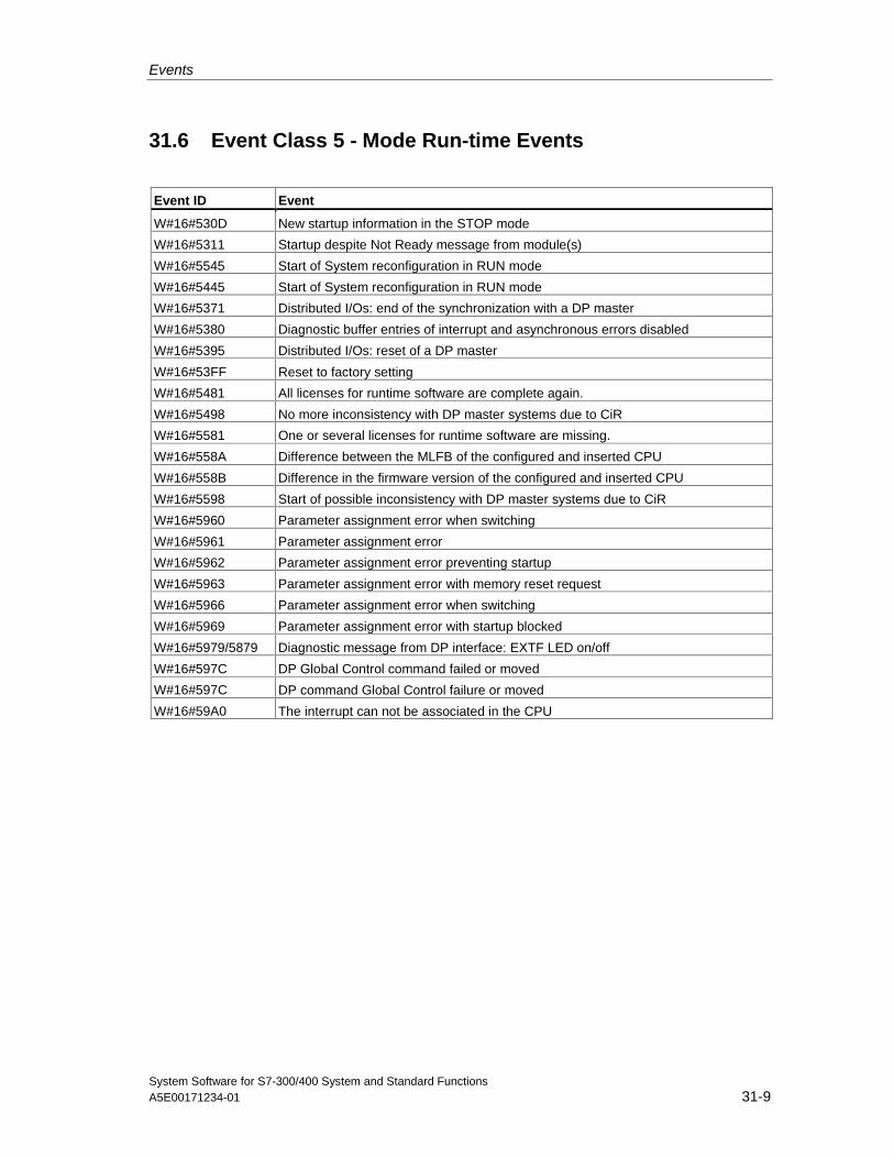
Events
System Software for S7-300/400 System and Standard FunctionsA5E00171234-01 31-9
31.6 Event Class 5 - Mode Run-time Events
Event ID Event
W#16#530D New startup information in the STOP mode
W#16#5311 Startup despite Not Ready message from module(s)
W#16#5545 Start of System reconfiguration in RUN mode
W#16#5445 Start of System reconfiguration in RUN mode
W#16#5371 Distributed I/Os: end of the synchronization with a DP master
W#16#5380 Diagnostic buffer entries of interrupt and asynchronous errors disabled
W#16#5395 Distributed I/Os: reset of a DP master
W#16#53FF Reset to factory setting
W#16#5481 All licenses for runtime software are complete again.
W#16#5498 No more inconsistency with DP master systems due to CiR
W#16#5581 One or several licenses for runtime software are missing.
W#16#558A Difference between the MLFB of the configured and inserted CPU
W#16#558B Difference in the firmware version of the configured and inserted CPU
W#16#5598 Start of possible inconsistency with DP master systems due to CiR
W#16#5960 Parameter assignment error when switching
W#16#5961 Parameter assignment error
W#16#5962 Parameter assignment error preventing startup
W#16#5963 Parameter assignment error with memory reset request
W#16#5966 Parameter assignment error when switching
W#16#5969 Parameter assignment error with startup blocked
W#16#5979/5879 Diagnostic message from DP interface: EXTF LED on/off
W#16#597C DP Global Control command failed or moved
W#16#597C DP command Global Control failure or moved
W#16#59A0 The interrupt can not be associated in the CPU
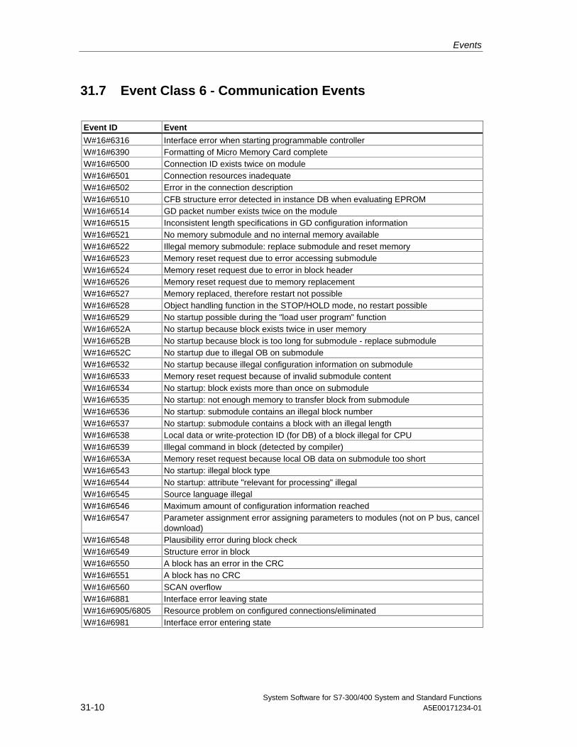
Events
System Software for S7-300/400 System and Standard Functions31-10 A5E00171234-01
31.7 Event Class 6 - Communication Events
Event ID Event
W#16#6316 Interface error when starting programmable controllerW#16#6390 Formatting of Micro Memory Card completeW#16#6500 Connection ID exists twice on moduleW#16#6501 Connection resources inadequateW#16#6502 Error in the connection descriptionW#16#6510 CFB structure error detected in instance DB when evaluating EPROMW#16#6514 GD packet number exists twice on the moduleW#16#6515 Inconsistent length specifications in GD configuration informationW#16#6521 No memory submodule and no internal memory availableW#16#6522 Illegal memory submodule: replace submodule and reset memoryW#16#6523 Memory reset request due to error accessing submoduleW#16#6524 Memory reset request due to error in block headerW#16#6526 Memory reset request due to memory replacementW#16#6527 Memory replaced, therefore restart not possibleW#16#6528 Object handling function in the STOP/HOLD mode, no restart possibleW#16#6529 No startup possible during the "load user program" functionW#16#652A No startup because block exists twice in user memoryW#16#652B No startup because block is too long for submodule - replace submoduleW#16#652C No startup due to illegal OB on submoduleW#16#6532 No startup because illegal configuration information on submoduleW#16#6533 Memory reset request because of invalid submodule contentW#16#6534 No startup: block exists more than once on submoduleW#16#6535 No startup: not enough memory to transfer block from submoduleW#16#6536 No startup: submodule contains an illegal block numberW#16#6537 No startup: submodule contains a block with an illegal lengthW#16#6538 Local data or write-protection ID (for DB) of a block illegal for CPUW#16#6539 Illegal command in block (detected by compiler)W#16#653A Memory reset request because local OB data on submodule too shortW#16#6543 No startup: illegal block typeW#16#6544 No startup: attribute "relevant for processing" illegalW#16#6545 Source language illegalW#16#6546 Maximum amount of configuration information reachedW#16#6547 Parameter assignment error assigning parameters to modules (not on P bus, cancel
download)W#16#6548 Plausibility error during block checkW#16#6549 Structure error in blockW#16#6550 A block has an error in the CRCW#16#6551 A block has no CRCW#16#6560 SCAN overflowW#16#6881 Interface error leaving stateW#16#6905/6805 Resource problem on configured connections/eliminatedW#16#6981 Interface error entering state
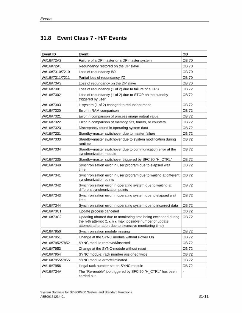
Events
System Software for S7-300/400 System and Standard FunctionsA5E00171234-01 31-11
31.8 Event Class 7 - H/F Events
Event ID Event OB
W#16#72A2 Failure of a DP master or a DP master system OB 70
W#16#72A3 Redundancy restored on the DP slave OB 70
W#16#7310/7210 Loss of redundancy I/O OB 70
W#16#7311/7211 Partial loss of redundancy I/O OB 70
W#16#73A3 Loss of redundancy on the DP slave OB 70
W#16#7301 Loss of redundancy (1 of 2) due to failure of a CPU OB 72
W#16#7302 Loss of redundancy (1 of 2) due to STOP on the standbytriggered by user
OB 72
W#16#7303 H system (1 of 2) changed to redundant mode OB 72
W#16#7320 Error in RAM comparison OB 72
W#16#7321 Error in comparison of process image output value OB 72
W#16#7322 Error in comparison of memory bits, timers, or counters OB 72
W#16#7323 Discrepancy found in operating system data OB 72
W#16#7331 Standby-master switchover due to master failure OB 72
W#16#7333 Standby-master switchover due to system modification duringruntime
OB 72
W#16#7334 Standby-master switchover due to communication error at thesynchronization module
OB 72
W#16#7335 Standby-master switchover triggered by SFC 90 "H_CTRL" OB 72
W#16#7340 Synchronization error in user program due to elapsed waittime
OB 72
W#16#7341 Synchronization error in user program due to waiting at differentsynchronization points
OB 72
W#16#7342 Synchronization error in operating system due to waiting atdifferent synchronization points
OB 72
W#16#7343 Synchronization error in operating system due to elapsed waittime
OB 72
W#16#7344 Synchronization error in operating system due to incorrect data OB 72
W#16#73C1 Update process canceled OB 72
W#16#73C2 Updating aborted due to monitoring time being exceeded duringthe n-th attempt (1 ≤ n ≤ max. possible number of updateattempts after abort due to excessive monitoring time)
OB 72
W#16#7950 Synchronization module missing OB 72
W#16#7951 Change at the SYNC module without Power On OB 72
W#16#7952/7852 SYNC module removed/inserted OB 72
W#16#7953 Change at the SYNC-module without reset OB 72
W#16#7954 SYNC module: rack number assigned twice OB 72
W#16#7955/7855 SYNC module error/eliminated OB 72
W#16#7956 Illegal rack number set on SYNC module OB 72
W#16#734A The "Re-enable" job triggered by SFC 90 "H_CTRL" has beencarried out.
-
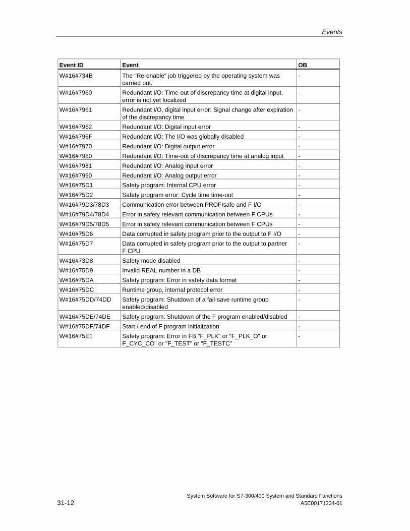
Events
System Software for S7-300/400 System and Standard Functions31-12 A5E00171234-01
Event ID Event OB
W#16#734B The "Re-enable" job triggered by the operating system wascarried out.
-
W#16#7960 Redundant I/O: Time-out of discrepancy time at digital input,error is not yet localized
-
W#16#7961 Redundant I/O, digital input error: Signal change after expirationof the discrepancy time
-
W#16#7962 Redundant I/O: Digital input error -
W#16#796F Redundant I/O: The I/O was globally disabled -
W#16#7970 Redundant I/O: Digital output error -
W#16#7980 Redundant I/O: Time-out of discrepancy time at analog input -
W#16#7981 Redundant I/O: Analog input error -
W#16#7990 Redundant I/O: Analog output error -
W#16#75D1 Safety program: Internal CPU error -
W#16#75D2 Safety program error: Cycle time time-out -
W#16#79D3/78D3 Communication error between PROFIsafe and F I/O -
W#16#79D4/78D4 Error in safety relevant communication between F CPUs -
W#16#79D5/78D5 Error in safety relevant communication between F CPUs -
W#16#75D6 Data corrupted in safety program prior to the output to F I/O -
W#16#75D7 Data corrupted in safety program prior to the output to partnerF CPU
-
W#16#73D8 Safety mode disabled -
W#16#75D9 Invalid REAL number in a DB -
W#16#75DA Safety program: Error in safety data format -
W#16#75DC Runtime group, internal protocol error -
W#16#75DD/74DD Safety program: Shutdown of a fail-save runtime groupenabled/disabled
-
W#16#75DE/74DE Safety program: Shutdown of the F program enabled/disabled -
W#16#75DF/74DF Start / end of F program initialization -
W#16#75E1 Safety program: Error in FB "F_PLK" or "F_PLK_O" orF_CYC_CO" or "F_TEST" or "F_TESTC"
-
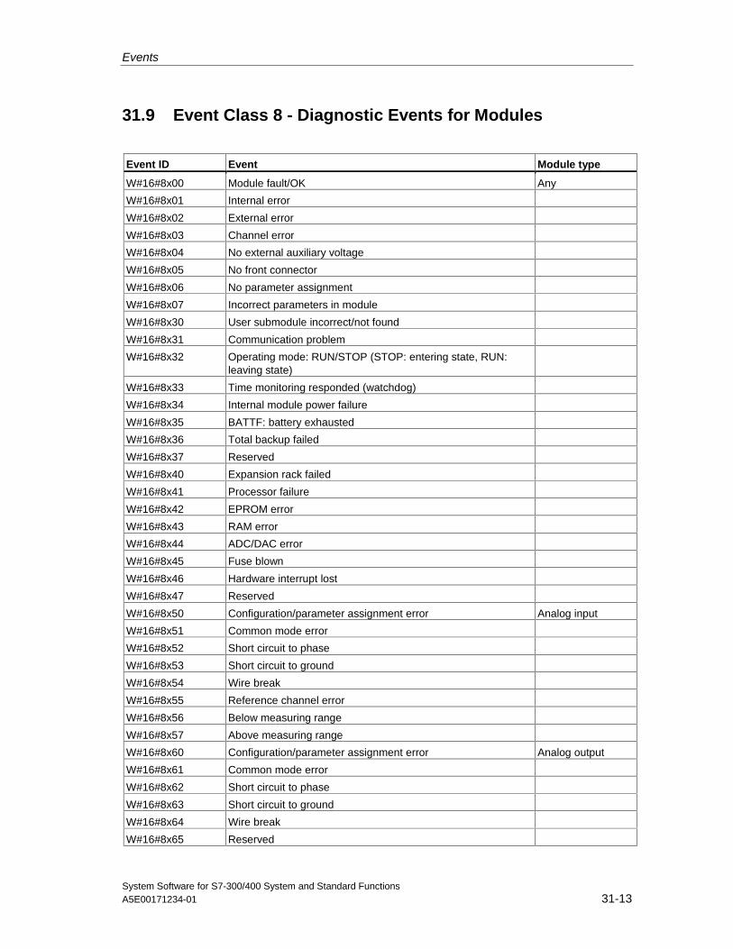
Events
System Software for S7-300/400 System and Standard FunctionsA5E00171234-01 31-13
31.9 Event Class 8 - Diagnostic Events for Modules
Event ID Event Module type
W#16#8x00 Module fault/OK Any
W#16#8x01 Internal error
W#16#8x02 External error
W#16#8x03 Channel error
W#16#8x04 No external auxiliary voltage
W#16#8x05 No front connector
W#16#8x06 No parameter assignment
W#16#8x07 Incorrect parameters in module
W#16#8x30 User submodule incorrect/not found
W#16#8x31 Communication problem
W#16#8x32 Operating mode: RUN/STOP (STOP: entering state, RUN:leaving state)
W#16#8x33 Time monitoring responded (watchdog)
W#16#8x34 Internal module power failure
W#16#8x35 BATTF: battery exhausted
W#16#8x36 Total backup failed
W#16#8x37 Reserved
W#16#8x40 Expansion rack failed
W#16#8x41 Processor failure
W#16#8x42 EPROM error
W#16#8x43 RAM error
W#16#8x44 ADC/DAC error
W#16#8x45 Fuse blown
W#16#8x46 Hardware interrupt lost
W#16#8x47 Reserved
W#16#8x50 Configuration/parameter assignment error Analog input
W#16#8x51 Common mode error
W#16#8x52 Short circuit to phase
W#16#8x53 Short circuit to ground
W#16#8x54 Wire break
W#16#8x55 Reference channel error
W#16#8x56 Below measuring range
W#16#8x57 Above measuring range
W#16#8x60 Configuration/parameter assignment error Analog output
W#16#8x61 Common mode error
W#16#8x62 Short circuit to phase
W#16#8x63 Short circuit to ground
W#16#8x64 Wire break
W#16#8x65 Reserved
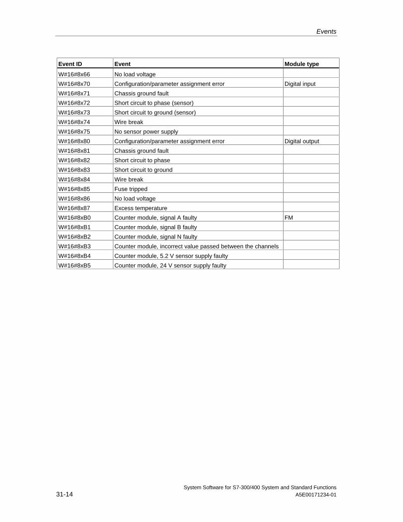
Events
System Software for S7-300/400 System and Standard Functions31-14 A5E00171234-01
Event ID Event Module type
W#16#8x66 No load voltage
W#16#8x70 Configuration/parameter assignment error Digital input
W#16#8x71 Chassis ground fault
W#16#8x72 Short circuit to phase (sensor)
W#16#8x73 Short circuit to ground (sensor)
W#16#8x74 Wire break
W#16#8x75 No sensor power supply
W#16#8x80 Configuration/parameter assignment error Digital output
W#16#8x81 Chassis ground fault
W#16#8x82 Short circuit to phase
W#16#8x83 Short circuit to ground
W#16#8x84 Wire break
W#16#8x85 Fuse tripped
W#16#8x86 No load voltage
W#16#8x87 Excess temperature
W#16#8xB0 Counter module, signal A faulty FM
W#16#8xB1 Counter module, signal B faulty
W#16#8xB2 Counter module, signal N faulty
W#16#8xB3 Counter module, incorrect value passed between the channels
W#16#8xB4 Counter module, 5.2 V sensor supply faulty
W#16#8xB5 Counter module, 24 V sensor supply faulty
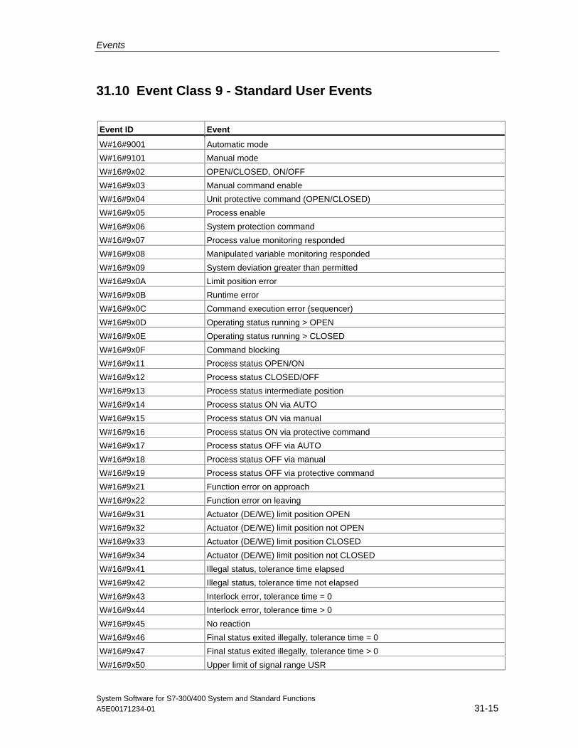
Events
System Software for S7-300/400 System and Standard FunctionsA5E00171234-01 31-15
31.10 Event Class 9 - Standard User Events
Event ID Event
W#16#9001 Automatic mode
W#16#9101 Manual mode
W#16#9x02 OPEN/CLOSED, ON/OFF
W#16#9x03 Manual command enable
W#16#9x04 Unit protective command (OPEN/CLOSED)
W#16#9x05 Process enable
W#16#9x06 System protection command
W#16#9x07 Process value monitoring responded
W#16#9x08 Manipulated variable monitoring responded
W#16#9x09 System deviation greater than permitted
W#16#9x0A Limit position error
W#16#9x0B Runtime error
W#16#9x0C Command execution error (sequencer)
W#16#9x0D Operating status running > OPEN
W#16#9x0E Operating status running > CLOSED
W#16#9x0F Command blocking
W#16#9x11 Process status OPEN/ON
W#16#9x12 Process status CLOSED/OFF
W#16#9x13 Process status intermediate position
W#16#9x14 Process status ON via AUTO
W#16#9x15 Process status ON via manual
W#16#9x16 Process status ON via protective command
W#16#9x17 Process status OFF via AUTO
W#16#9x18 Process status OFF via manual
W#16#9x19 Process status OFF via protective command
W#16#9x21 Function error on approach
W#16#9x22 Function error on leaving
W#16#9x31 Actuator (DE/WE) limit position OPEN
W#16#9x32 Actuator (DE/WE) limit position not OPEN
W#16#9x33 Actuator (DE/WE) limit position CLOSED
W#16#9x34 Actuator (DE/WE) limit position not CLOSED
W#16#9x41 Illegal status, tolerance time elapsed
W#16#9x42 Illegal status, tolerance time not elapsed
W#16#9x43 Interlock error, tolerance time = 0
W#16#9x44 Interlock error, tolerance time > 0
W#16#9x45 No reaction
W#16#9x46 Final status exited illegally, tolerance time = 0
W#16#9x47 Final status exited illegally, tolerance time > 0
W#16#9x50 Upper limit of signal range USR
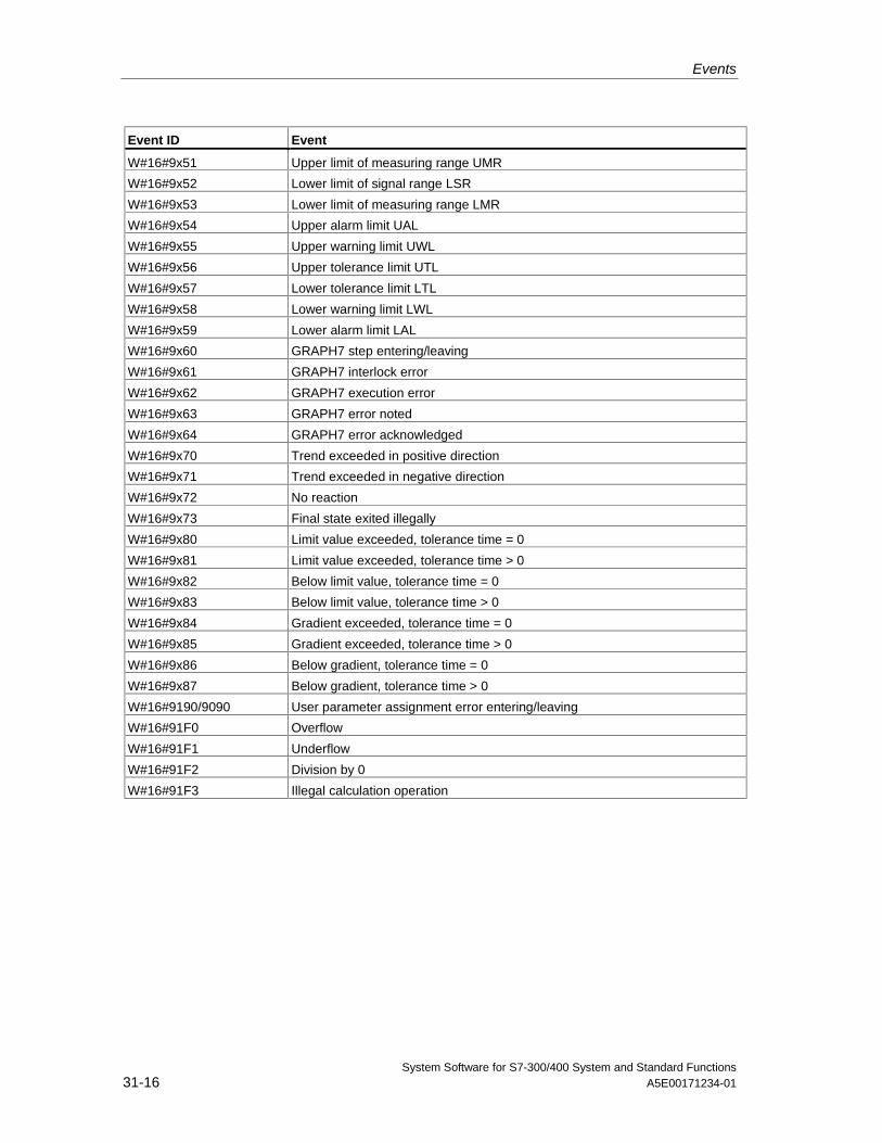
Events
System Software for S7-300/400 System and Standard Functions31-16 A5E00171234-01
Event ID Event
W#16#9x51 Upper limit of measuring range UMR
W#16#9x52 Lower limit of signal range LSR
W#16#9x53 Lower limit of measuring range LMR
W#16#9x54 Upper alarm limit UAL
W#16#9x55 Upper warning limit UWL
W#16#9x56 Upper tolerance limit UTL
W#16#9x57 Lower tolerance limit LTL
W#16#9x58 Lower warning limit LWL
W#16#9x59 Lower alarm limit LAL
W#16#9x60 GRAPH7 step entering/leaving
W#16#9x61 GRAPH7 interlock error
W#16#9x62 GRAPH7 execution error
W#16#9x63 GRAPH7 error noted
W#16#9x64 GRAPH7 error acknowledged
W#16#9x70 Trend exceeded in positive direction
W#16#9x71 Trend exceeded in negative direction
W#16#9x72 No reaction
W#16#9x73 Final state exited illegally
W#16#9x80 Limit value exceeded, tolerance time = 0
W#16#9x81 Limit value exceeded, tolerance time > 0
W#16#9x82 Below limit value, tolerance time = 0
W#16#9x83 Below limit value, tolerance time > 0
W#16#9x84 Gradient exceeded, tolerance time = 0
W#16#9x85 Gradient exceeded, tolerance time > 0
W#16#9x86 Below gradient, tolerance time = 0
W#16#9x87 Below gradient, tolerance time > 0
W#16#9190/9090 User parameter assignment error entering/leaving
W#16#91F0 Overflow
W#16#91F1 Underflow
W#16#91F2 Division by 0
W#16#91F3 Illegal calculation operation
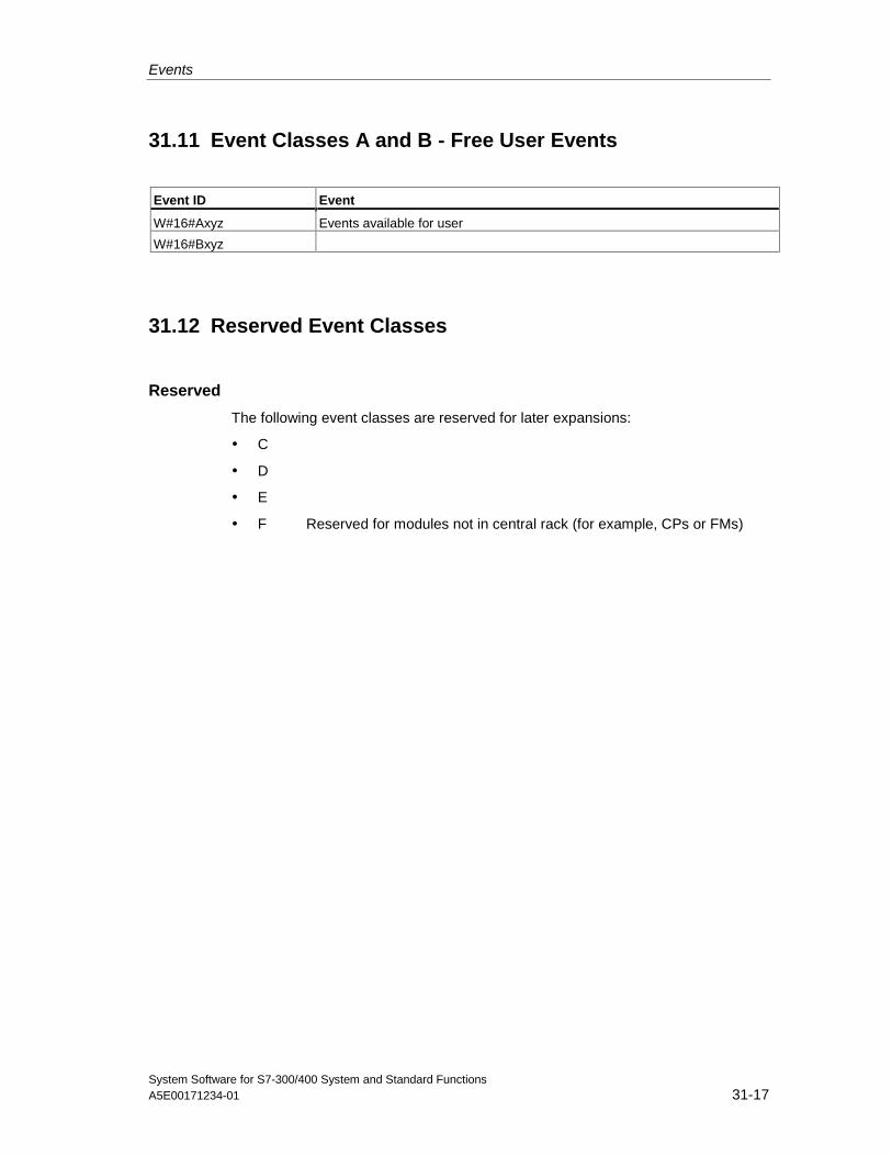
Events
System Software for S7-300/400 System and Standard FunctionsA5E00171234-01 31-17
31.11 Event Classes A and B - Free User Events
Event ID Event
W#16#Axyz Events available for user
W#16#Bxyz
31.12 Reserved Event Classes
Reserved
The following event classes are reserved for later expansions:
• C
• D
• E
• F Reserved for modules not in central rack (for example, CPs or FMs)

Events
System Software for S7-300/400 System and Standard Functions31-18 A5E00171234-01
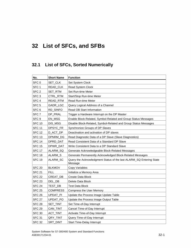
System Software for S7-300/400 System and Standard FunctionsA5E00171234-01 32-1
32 List of SFCs, and SFBs
32.1 List of SFCs, Sorted Numerically
No. Short Name Function
SFC 0 SET_CLK Set System Clock
SFC 1 READ_CLK Read System Clock
SFC 2 SET_RTM Set Run-time Meter
SFC 3 CTRL_RTM Start/Stop Run-time Meter
SFC 4 READ_RTM Read Run-time Meter
SFC 5 GADR_LGC Query Logical Address of a Channel
SFC 6 RD_SINFO Read OB Start Information
SFC 7 DP_PRAL Trigger a Hardware Interrupt on the DP Master
SFC 9 EN_MSG Enable Block-Related, Symbol-Related and Group Status Messages
SFC 10 DIS_MSG Disable Block-Related, Symbol-Related and Group Status Messages
SFC 11 DPSYC_FR Synchronize Groups of DP Slaves
SFC 12 D_ACT_DP Deactivation and activation of DP slaves
SFC 13 DPNRM_DG Read Diagnostic Data of a DP Slave (Slave Diagnostics)
SFC 14 DPRD_DAT Read Consistent Data of a Standard DP Slave
SFC 15 DPWR_DAT Write Consistent Data to a DP Standard Slave
SFC 17 ALARM_SQ Generate Acknowledgeable Block-Related Messages
SFC 18 ALARM_S Generate Permanently Acknowledged Block-Related Messages
SFC 19 ALARM_SC Query the Acknowledgment Status of the last ALARM_SQ Entering StateMessage
SFC 20 BLKMOV Copy Variables
SFC 21 FILL Initialize a Memory Area
SFC 22 CREAT_DB Create Data Block
SFC 23 DEL_DB Delete Data Block
SFC 24 TEST_DB Test Data Block
SFC 25 COMPRESS Compress the User Memory
SFC 26 UPDAT_PI Update the Process Image Update Table
SFC 27 UPDAT_PO Update the Process Image Output Table
SFC 28 SET_TINT Set Time-of-Day Interrupt
SFC 29 CAN_TINT Cancel Time-of-Day Interrupt
SFC 30 ACT_TINT Activate Time-of-Day Interrupt
SFC 31 QRY_TINT Query Time-of-Day Interrupt
SFC 32 SRT_DINT Start Time-Delay Interrupt
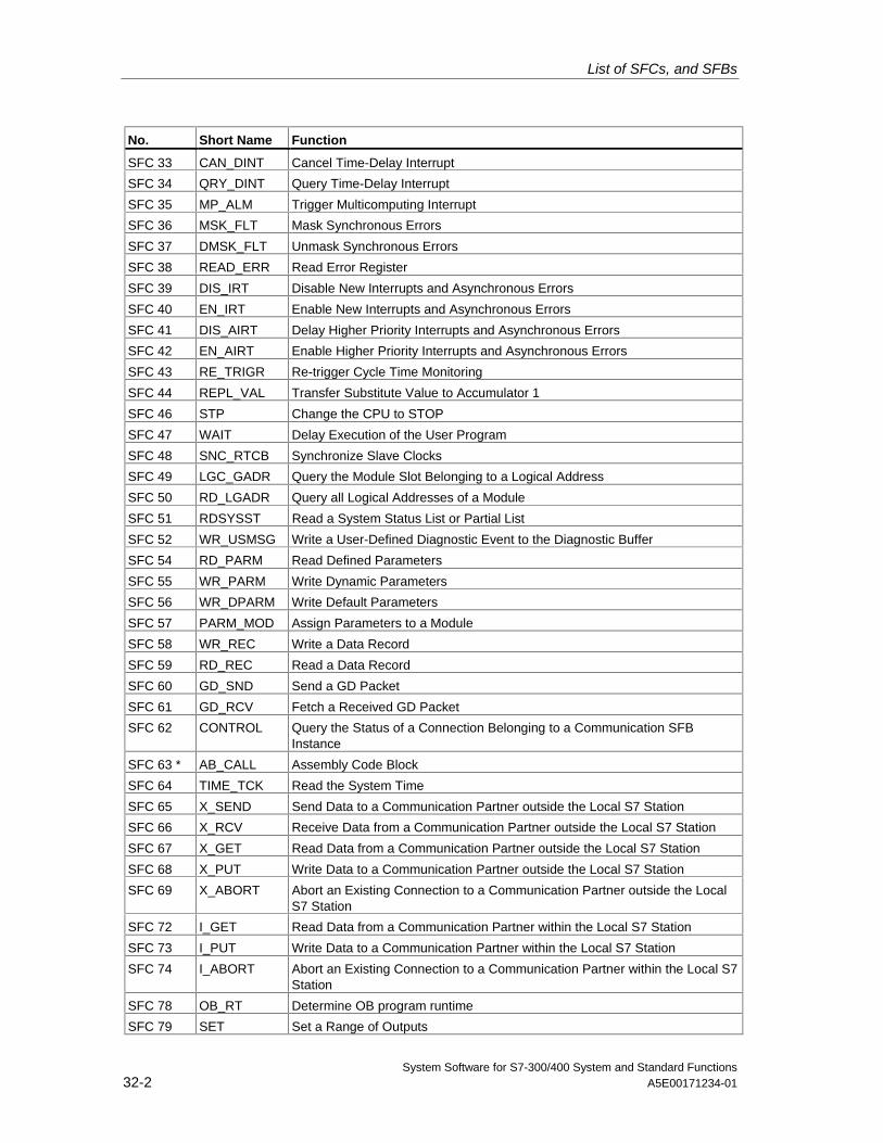
List of SFCs, and SFBs
System Software for S7-300/400 System and Standard Functions32-2 A5E00171234-01
No. Short Name Function
SFC 33 CAN_DINT Cancel Time-Delay Interrupt
SFC 34 QRY_DINT Query Time-Delay Interrupt
SFC 35 MP_ALM Trigger Multicomputing Interrupt
SFC 36 MSK_FLT Mask Synchronous Errors
SFC 37 DMSK_FLT Unmask Synchronous Errors
SFC 38 READ_ERR Read Error Register
SFC 39 DIS_IRT Disable New Interrupts and Asynchronous Errors
SFC 40 EN_IRT Enable New Interrupts and Asynchronous Errors
SFC 41 DIS_AIRT Delay Higher Priority Interrupts and Asynchronous Errors
SFC 42 EN_AIRT Enable Higher Priority Interrupts and Asynchronous Errors
SFC 43 RE_TRIGR Re-trigger Cycle Time Monitoring
SFC 44 REPL_VAL Transfer Substitute Value to Accumulator 1
SFC 46 STP Change the CPU to STOP
SFC 47 WAIT Delay Execution of the User Program
SFC 48 SNC_RTCB Synchronize Slave Clocks
SFC 49 LGC_GADR Query the Module Slot Belonging to a Logical Address
SFC 50 RD_LGADR Query all Logical Addresses of a Module
SFC 51 RDSYSST Read a System Status List or Partial List
SFC 52 WR_USMSG Write a User-Defined Diagnostic Event to the Diagnostic Buffer
SFC 54 RD_PARM Read Defined Parameters
SFC 55 WR_PARM Write Dynamic Parameters
SFC 56 WR_DPARM Write Default Parameters
SFC 57 PARM_MOD Assign Parameters to a Module
SFC 58 WR_REC Write a Data Record
SFC 59 RD_REC Read a Data Record
SFC 60 GD_SND Send a GD Packet
SFC 61 GD_RCV Fetch a Received GD Packet
SFC 62 CONTROL Query the Status of a Connection Belonging to a Communication SFBInstance
SFC 63 * AB_CALL Assembly Code Block
SFC 64 TIME_TCK Read the System Time
SFC 65 X_SEND Send Data to a Communication Partner outside the Local S7 Station
SFC 66 X_RCV Receive Data from a Communication Partner outside the Local S7 Station
SFC 67 X_GET Read Data from a Communication Partner outside the Local S7 Station
SFC 68 X_PUT Write Data to a Communication Partner outside the Local S7 Station
SFC 69 X_ABORT Abort an Existing Connection to a Communication Partner outside the LocalS7 Station
SFC 72 I_GET Read Data from a Communication Partner within the Local S7 Station
SFC 73 I_PUT Write Data to a Communication Partner within the Local S7 Station
SFC 74 I_ABORT Abort an Existing Connection to a Communication Partner within the Local S7Station
SFC 78 OB_RT Determine OB program runtime
SFC 79 SET Set a Range of Outputs
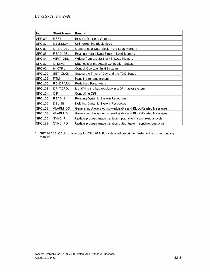
List of SFCs, and SFBs
System Software for S7-300/400 System and Standard FunctionsA5E00171234-01 32-3
No. Short Name Function
SFC 80 RSET Reset a Range of Outputs
SFC 81 UBLKMOV Uninterruptible Block Move
SFC 82 CREA_DBL Generating a Data Block in the Load Memory
SFC 83 READ_DBL Reading from a Data Block in Load Memory
SFC 84 WRIT_DBL Writing from a Data Block in Load Memory
SFC 87 C_DIAG Diagnosis of the Actual Connection Status
SFC 90 H_CTRL Control Operation in H Systems
SFC 100 SET_CLKS Setting the Time-of-Day and the TOD Status
SFC 101 RTM Handling runtime meters
SFC 102 RD_DPARA Redefined Parameters
SFC 103 DP_TOPOL Identifying the bus topology in a DP master system
SFC 104 CiR Controlling CiR
SFC 105 READ_SI Reading Dynamic System Resources
SFC 106 DEL_SI Deleting Dynamic System Resources
SFC 107 ALARM_DQ Generating Always Acknowledgeable and Block-Related Messages
SFC 108 ALARM_D Generating Always Acknowledgeable and Block-Related Messages
SFC 126 SYNC_PI Update process image partition input table in synchronous cycle
SFC 127 SYNC_PO Update process image partition output table in synchronous cycle
* SFC 63 "AB_CALL" only exists for CPU 614. For a detailed description, refer to the correspondingmanual.
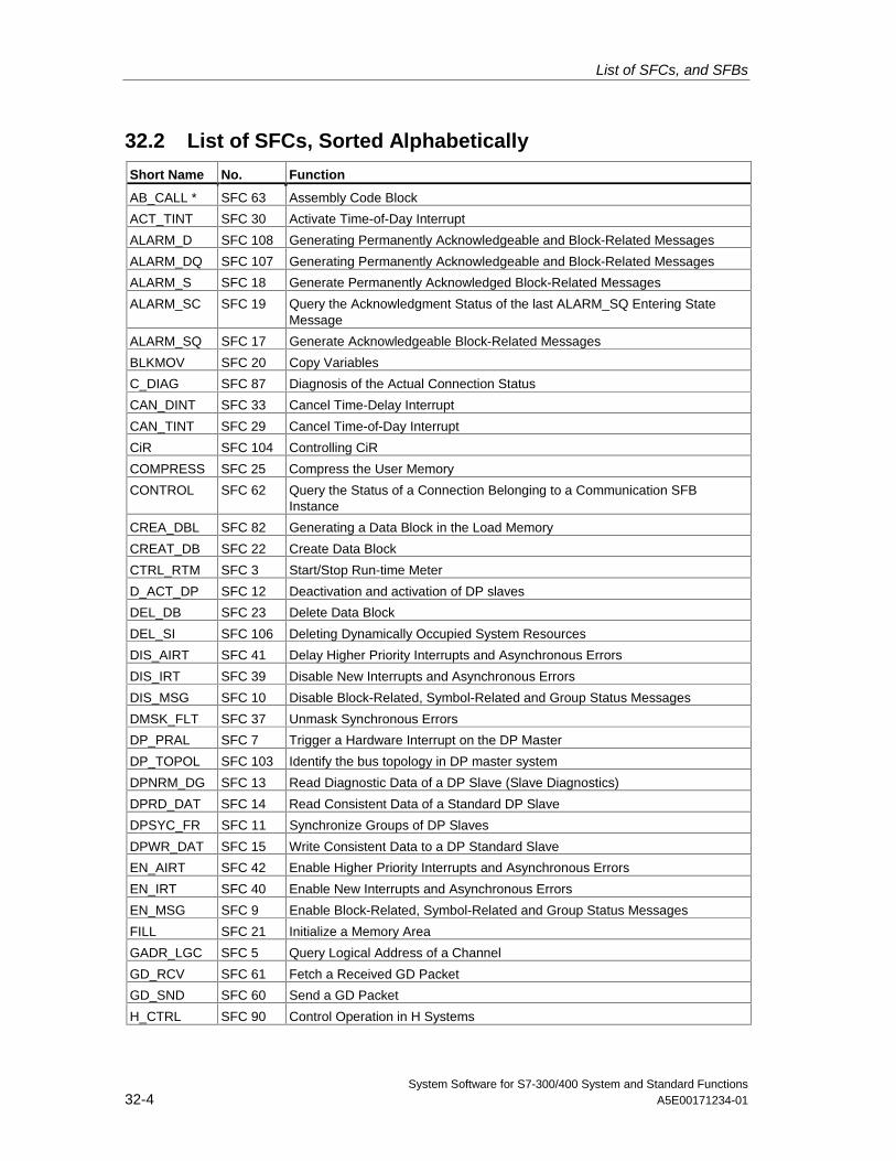
List of SFCs, and SFBs
System Software for S7-300/400 System and Standard Functions32-4 A5E00171234-01
32.2 List of SFCs, Sorted Alphabetically
Short Name No. Function
AB_CALL * SFC 63 Assembly Code Block
ACT_TINT SFC 30 Activate Time-of-Day Interrupt
ALARM_D SFC 108 Generating Permanently Acknowledgeable and Block-Related Messages
ALARM_DQ SFC 107 Generating Permanently Acknowledgeable and Block-Related Messages
ALARM_S SFC 18 Generate Permanently Acknowledged Block-Related Messages
ALARM_SC SFC 19 Query the Acknowledgment Status of the last ALARM_SQ Entering StateMessage
ALARM_SQ SFC 17 Generate Acknowledgeable Block-Related Messages
BLKMOV SFC 20 Copy Variables
C_DIAG SFC 87 Diagnosis of the Actual Connection Status
CAN_DINT SFC 33 Cancel Time-Delay Interrupt
CAN_TINT SFC 29 Cancel Time-of-Day Interrupt
CiR SFC 104 Controlling CiR
COMPRESS SFC 25 Compress the User Memory
CONTROL SFC 62 Query the Status of a Connection Belonging to a Communication SFBInstance
CREA_DBL SFC 82 Generating a Data Block in the Load Memory
CREAT_DB SFC 22 Create Data Block
CTRL_RTM SFC 3 Start/Stop Run-time Meter
D_ACT_DP SFC 12 Deactivation and activation of DP slaves
DEL_DB SFC 23 Delete Data Block
DEL_SI SFC 106 Deleting Dynamically Occupied System Resources
DIS_AIRT SFC 41 Delay Higher Priority Interrupts and Asynchronous Errors
DIS_IRT SFC 39 Disable New Interrupts and Asynchronous Errors
DIS_MSG SFC 10 Disable Block-Related, Symbol-Related and Group Status Messages
DMSK_FLT SFC 37 Unmask Synchronous Errors
DP_PRAL SFC 7 Trigger a Hardware Interrupt on the DP Master
DP_TOPOL SFC 103 Identify the bus topology in DP master system
DPNRM_DG SFC 13 Read Diagnostic Data of a DP Slave (Slave Diagnostics)
DPRD_DAT SFC 14 Read Consistent Data of a Standard DP Slave
DPSYC_FR SFC 11 Synchronize Groups of DP Slaves
DPWR_DAT SFC 15 Write Consistent Data to a DP Standard Slave
EN_AIRT SFC 42 Enable Higher Priority Interrupts and Asynchronous Errors
EN_IRT SFC 40 Enable New Interrupts and Asynchronous Errors
EN_MSG SFC 9 Enable Block-Related, Symbol-Related and Group Status Messages
FILL SFC 21 Initialize a Memory Area
GADR_LGC SFC 5 Query Logical Address of a Channel
GD_RCV SFC 61 Fetch a Received GD Packet
GD_SND SFC 60 Send a GD Packet
H_CTRL SFC 90 Control Operation in H Systems
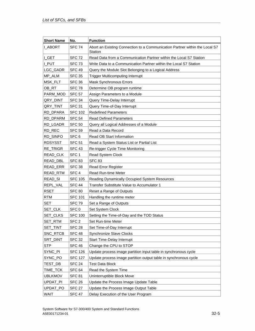
List of SFCs, and SFBs
System Software for S7-300/400 System and Standard FunctionsA5E00171234-01 32-5
Short Name No. Function
I_ABORT SFC 74 Abort an Existing Connection to a Communication Partner within the Local S7Station
I_GET SFC 72 Read Data from a Communication Partner within the Local S7 Station
I_PUT SFC 73 Write Data to a Communication Partner within the Local S7 Station
LGC_GADR SFC 49 Query the Module Slot Belonging to a Logical Address
MP_ALM SFC 35 Trigger Multicomputing Interrupt
MSK_FLT SFC 36 Mask Synchronous Errors
OB_RT SFC 78 Determine OB program runtime
PARM_MOD SFC 57 Assign Parameters to a Module
QRY_DINT SFC 34 Query Time-Delay Interrupt
QRY_TINT SFC 31 Query Time-of-Day Interrupt
RD_DPARA SFC 102 Redefined Parameters
RD_DPARM SFC 54 Read Defined Parameters
RD_LGADR SFC 50 Query all Logical Addresses of a Module
RD_REC SFC 59 Read a Data Record
RD_SINFO SFC 6 Read OB Start Information
RDSYSST SFC 51 Read a System Status List or Partial List
RE_TRIGR SFC 43 Re-trigger Cycle Time Monitoring
READ_CLK SFC 1 Read System Clock
READ_DBL SFC 83 SFC 83
READ_ERR SFC 38 Read Error Register
READ_RTM SFC 4 Read Run-time Meter
READ_SI SFC 105 Reading Dynamically Occupied System Resources
REPL_VAL SFC 44 Transfer Substitute Value to Accumulator 1
RSET SFC 80 Reset a Range of Outputs
RTM SFC 101 Handling the runtime meter
SET SFC 79 Set a Range of Outputs
SET_CLK SFC 0 Set System Clock
SET_CLKS SFC 100 Setting the Time-of-Day and the TOD Status
SET_RTM SFC 2 Set Run-time Meter
SET_TINT SFC 28 Set Time-of-Day Interrupt
SNC_RTCB SFC 48 Synchronize Slave Clocks
SRT_DINT SFC 32 Start Time-Delay Interrupt
STP SFC 46 Change the CPU to STOP
SYNC_PI SFC 126 Update process image partition input table in synchronous cycle
SYNC_PO SFC 127 Update process image partition output table in synchronous cycle
TEST_DB SFC 24 Test Data Block
TIME_TCK SFC 64 Read the System Time
UBLKMOV SFC 81 Uninterruptible Block Move
UPDAT_PI SFC 26 Update the Process Image Update Table
UPDAT_PO SFC 27 Update the Process Image Output Table
WAIT SFC 47 Delay Execution of the User Program
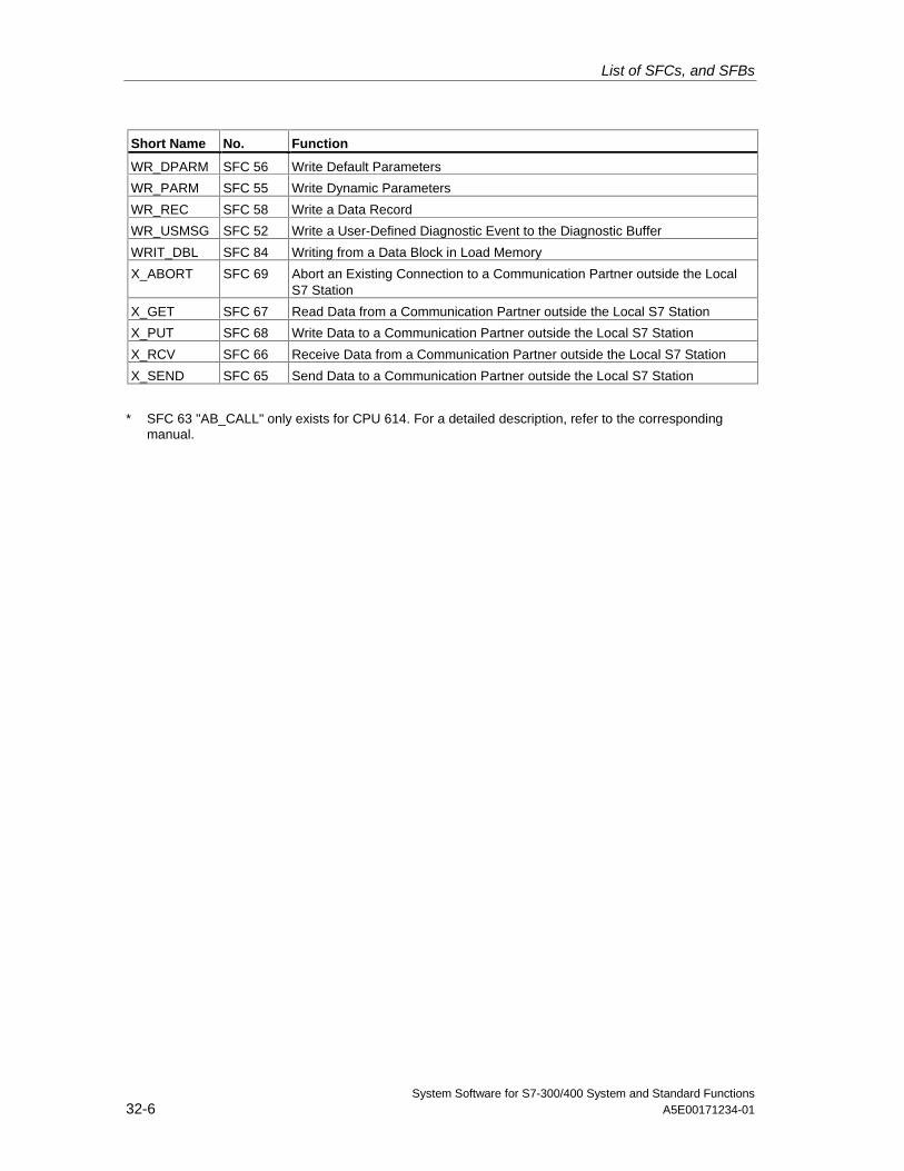
List of SFCs, and SFBs
System Software for S7-300/400 System and Standard Functions32-6 A5E00171234-01
Short Name No. Function
WR_DPARM SFC 56 Write Default Parameters
WR_PARM SFC 55 Write Dynamic Parameters
WR_REC SFC 58 Write a Data Record
WR_USMSG SFC 52 Write a User-Defined Diagnostic Event to the Diagnostic Buffer
WRIT_DBL SFC 84 Writing from a Data Block in Load Memory
X_ABORT SFC 69 Abort an Existing Connection to a Communication Partner outside the LocalS7 Station
X_GET SFC 67 Read Data from a Communication Partner outside the Local S7 Station
X_PUT SFC 68 Write Data to a Communication Partner outside the Local S7 Station
X_RCV SFC 66 Receive Data from a Communication Partner outside the Local S7 Station
X_SEND SFC 65 Send Data to a Communication Partner outside the Local S7 Station
* SFC 63 "AB_CALL" only exists for CPU 614. For a detailed description, refer to the correspondingmanual.
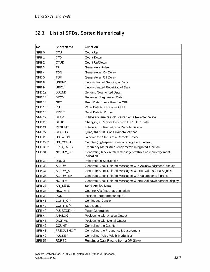
List of SFCs, and SFBs
System Software for S7-300/400 System and Standard FunctionsA5E00171234-01 32-7
32.3 List of SFBs, Sorted Numerically
No. Short Name Function
SFB 0 CTU Count Up
SFB 1 CTD Count Down
SFB 2 CTUD Count Up/Down
SFB 3 TP Generate a Pulse
SFB 4 TON Generate an On Delay
SFB 5 TOF Generate an Off Delay
SFB 8 USEND Uncoordinated Sending of Data
SFB 9 URCV Uncoordinated Receiving of Data
SFB 12 BSEND Sending Segmented Data
SFB 13 BRCV Receiving Segmented Data
SFB 14 GET Read Data from a Remote CPU
SFB 15 PUT Write Data to a Remote CPU
SFB 16 PRINT Send Data to Printer
SFB 19 START Initiate a Warm or Cold Restart on a Remote Device
SFB 20 STOP Changing a Remote Device to the STOP State
SFB 21 RESUME Initiate a Hot Restart on a Remote Device
SFB 22 STATUS Query the Status of a Remote Partner
SFB 23 USTATUS Receive the Status of a Remote Device
SFB 29 * HS_COUNT Counter (high-speed counter, integrated function)
SFB 30 * FREQ_MES Frequency Meter (frequency meter, integrated function
SFB 31 NOTIFY_8P Generating block related messages without acknowledgementindication
SFB 32 DRUM Implement a Sequencer
SFB 33 ALARM Generate Block-Related Messages with Acknowledgment Display
SFB 34 ALARM_8 Generate Block-Related Messages without Values for 8 Signals
SFB 35 ALARM_8P Generate Block-Related Messages with Values for 8 Signals
SFB 36 NOTIFY Generate Block-Related Messages without Acknowledgment Display
SFB 37 AR_SEND Send Archive Data
SFB 38 * HSC_A_B Counter A/B (integrated function)
SFB 39 * POS Position (integrated function)
SFB 41 CONT_C 1) Continuous Control
SFB 42 CONT_S 1) Step Control
SFB 43 PULSEGEN 1) Pulse Generation
SFB 44 ANALOG 2) Positioning with Analog Output
SFB 46 DIGITAL 2) Positioning with Digital Output
SFB 47 COUNT 2) Controlling the Counter
SFB 48 FREQUENC 2) Controlling the Frequency Measurement
SFB 49 PULSE 2) Controlling Pulse Width Modulation
SFB 52 RDREC Reading a Data Record from a DP Slave
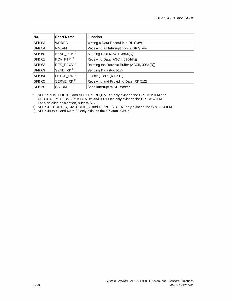
List of SFCs, and SFBs
System Software for S7-300/400 System and Standard Functions32-8 A5E00171234-01
No. Short Name Function
SFB 53 WRREC Writing a Data Record in a DP Slave
SFB 54 RALRM Receiving an Interrupt from a DP Slave
SFB 60 SEND_PTP 2) Sending Data (ASCII, 3964(R))
SFB 61 RCV_PTP 2) Receiving Data (ASCII, 3964(R))
SFB 62 RES_RECV 2) Deleting the Receive Buffer (ASCII, 3964(R))
SFB 63 SEND_RK 2) Sending Data (RK 512)
SFB 64 FETCH_RK 2) Fetching Data (RK 512)
SFB 65 SERVE_RK 2) Receiving and Providing Data (RK 512)
SFB 75 SALRM Send interrupt to DP master
* SFB 29 "HS_COUNT" and SFB 30 "FREQ_MES" only exist on the CPU 312 IFM andCPU 314 IFM. SFBs 38 "HSC_A_B" and 39 "POS" only exist on the CPU 314 IFM.For a detailed description, refer to /73/.
1) SFBs 41 "CONT_C," 42 "CONT_S" and 43 "PULSEGEN" only exist on the CPU 314 IFM.2) SFBs 44 to 49 and 60 to 65 only exist on the S7-300C CPUs.
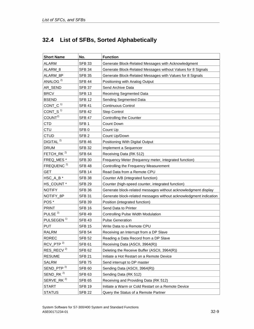
List of SFCs, and SFBs
System Software for S7-300/400 System and Standard FunctionsA5E00171234-01 32-9
32.4 List of SFBs, Sorted Alphabetically
Short Name No. Function
ALARM SFB 33 Generate Block-Related Messages with Acknowledgment
ALARM_8 SFB 34 Generate Block-Related Messages without Values for 8 Signals
ALARM_8P SFB 35 Generate Block-Related Messages with Values for 8 Signals
ANALOG 2) SFB 44 Positioning with Analog Output
AR_SEND SFB 37 Send Archive Data
BRCV SFB 13 Receiving Segmented Data
BSEND SFB 12 Sending Segmented Data
CONT_C 1) SFB 41 Continuous Control
CONT_S 1) SFB 42 Step Control
COUNT2) SFB 47 Controlling the Counter
CTD SFB 1 Count Down
CTU SFB 0 Count Up
CTUD SFB 2 Count Up/Down
DIGITAL 2) SFB 46 Positioning With Digital Output
DRUM SFB 32 Implement a Sequencer
FETCH_RK 2) SFB 64 Receiving Data (RK 512)
FREQ_MES * SFB 30 Frequency Meter (frequency meter, integrated function)
FREQUENC 2) SFB 48 Controlling the Frequency Measurement
GET SFB 14 Read Data from a Remote CPU
HSC_A_B * SFB 38 Counter A/B (integrated function)
HS_COUNT * SFB 29 Counter (high-speed counter, integrated function)
NOTIFY SFB 36 Generate block-related messages without acknowledgment display
NOTIFY_8P SFB 31 Generate block-related messages without acknowledgment indication
POS * SFB 39 Position (integrated function)
PRINT SFB 16 Send Data to Printer
PULSE 2) SFB 49 Controlling Pulse Width Modulation
PULSEGEN 1) SFB 43 Pulse Generation
PUT SFB 15 Write Data to a Remote CPU
RALRM SFB 54 Receiving an Interrupt from a DP Slave
RDREC SFB 52 Reading a Data Record from a DP Slave
RCV_PTP 2) SFB 61 Receiving Data (ASCII, 3964(R))
RES_RECV 2) SFB 62 Deleting the Receive Buffer (ASCII, 3964(R))
RESUME SFB 21 Initiate a Hot Restart on a Remote Device
SALRM SFB 75 Send interrupt to DP master
SEND_PTP 2) SFB 60 Sending Data (ASCII, 3964(R))
SEND_RK 2) SFB 63 Sending Data (RK 512)
SERVE_RK 2) SFB 65 Receiving and Providing Data (RK 512)
START SFB 19 Initiate a Warm or Cold Restart on a Remote Device
STATUS SFB 22 Query the Status of a Remote Partner
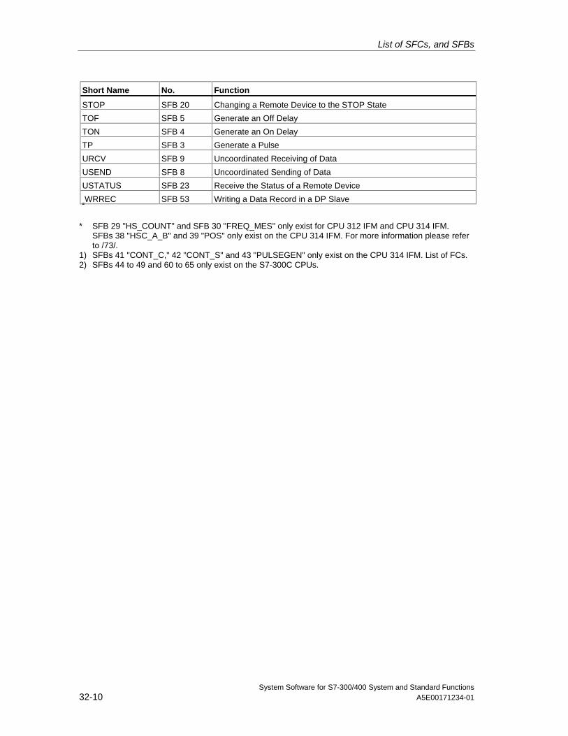
List of SFCs, and SFBs
System Software for S7-300/400 System and Standard Functions32-10 A5E00171234-01
Short Name No. Function
STOP SFB 20 Changing a Remote Device to the STOP State
TOF SFB 5 Generate an Off Delay
TON SFB 4 Generate an On Delay
TP SFB 3 Generate a Pulse
URCV SFB 9 Uncoordinated Receiving of Data
USEND SFB 8 Uncoordinated Sending of Data
USTATUS SFB 23 Receive the Status of a Remote Device
WRREC SFB 53 Writing a Data Record in a DP Slave
* SFB 29 "HS_COUNT" and SFB 30 "FREQ_MES" only exist for CPU 312 IFM and CPU 314 IFM.SFBs 38 "HSC_A_B" and 39 "POS" only exist on the CPU 314 IFM. For more information please referto /73/.
1) SFBs 41 "CONT_C," 42 "CONT_S" and 43 "PULSEGEN" only exist on the CPU 314 IFM. List of FCs.2) SFBs 44 to 49 and 60 to 65 only exist on the S7-300C CPUs.
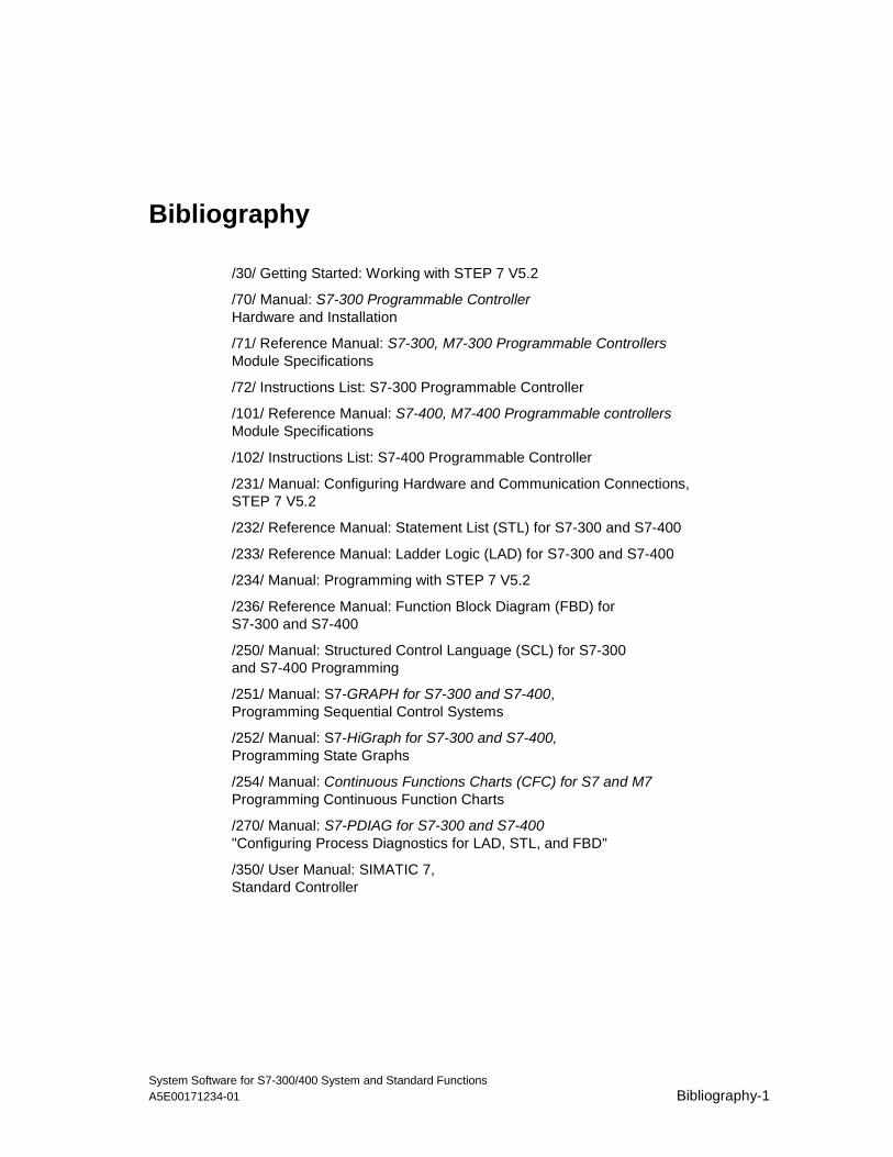
System Software for S7-300/400 System and Standard FunctionsA5E00171234-01 Bibliography-1
Bibliography
/30/ Getting Started: Working with STEP 7 V5.2
/70/ Manual: S7-300 Programmable ControllerHardware and Installation
/71/ Reference Manual: S7-300, M7-300 Programmable ControllersModule Specifications
/72/ Instructions List: S7-300 Programmable Controller
/101/ Reference Manual: S7-400, M7-400 Programmable controllersModule Specifications
/102/ Instructions List: S7-400 Programmable Controller
/231/ Manual: Configuring Hardware and Communication Connections,STEP 7 V5.2
/232/ Reference Manual: Statement List (STL) for S7-300 and S7-400
/233/ Reference Manual: Ladder Logic (LAD) for S7-300 and S7-400
/234/ Manual: Programming with STEP 7 V5.2
/236/ Reference Manual: Function Block Diagram (FBD) forS7-300 and S7-400
/250/ Manual: Structured Control Language (SCL) for S7-300and S7-400 Programming
/251/ Manual: S7-GRAPH for S7-300 and S7-400,Programming Sequential Control Systems
/252/ Manual: S7-HiGraph for S7-300 and S7-400,Programming State Graphs
/254/ Manual: Continuous Functions Charts (CFC) for S7 and M7Programming Continuous Function Charts
/270/ Manual: S7-PDIAG for S7-300 and S7-400"Configuring Process Diagnostics for LAD, STL, and FBD"
/350/ User Manual: SIMATIC 7,Standard Controller

Bibliography
System Software for S7-300/400 System and Standard FunctionsBibliography-2 A5E00171234-01
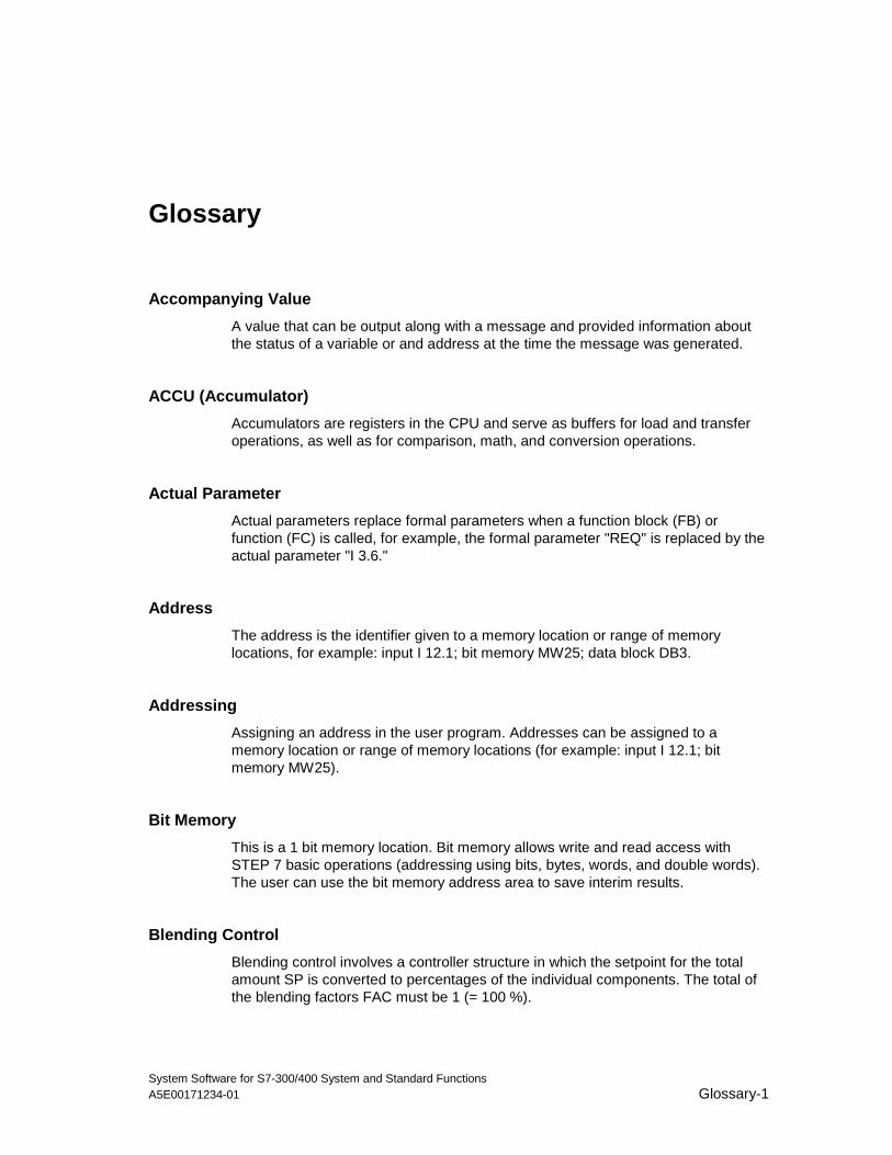
System Software for S7-300/400 System and Standard FunctionsA5E00171234-01 Glossary-1
Glossary
Accompanying Value
A value that can be output along with a message and provided information aboutthe status of a variable or and address at the time the message was generated.
ACCU (Accumulator)
Accumulators are registers in the CPU and serve as buffers for load and transferoperations, as well as for comparison, math, and conversion operations.
Actual Parameter
Actual parameters replace formal parameters when a function block (FB) orfunction (FC) is called, for example, the formal parameter "REQ" is replaced by theactual parameter "I 3.6."
Address
The address is the identifier given to a memory location or range of memorylocations, for example: input I 12.1; bit memory MW25; data block DB3.
Addressing
Assigning an address in the user program. Addresses can be assigned to amemory location or range of memory locations (for example: input I 12.1; bitmemory MW25).
Bit Memory
This is a 1 bit memory location. Bit memory allows write and read access withSTEP 7 basic operations (addressing using bits, bytes, words, and double words).The user can use the bit memory address area to save interim results.
Blending Control
Blending control involves a controller structure in which the setpoint for the totalamount SP is converted to percentages of the individual components. The total ofthe blending factors FAC must be 1 (= 100 %).
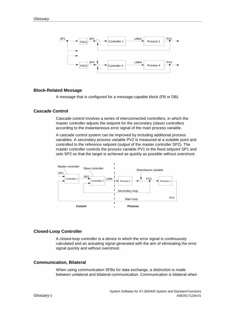
Glossary
System Software for S7-300/400 System and Standard FunctionsGlossary-2 A5E00171234-01
-Controller 1 Process 1
-Process 4Controller 4
FAC1SP1
FAC4SP4
SP1 LMN1 PV1
LMN4 PV4
Block-Related MessageA message that is configured for a message-capable block (FB or DB).
Cascade Control
Cascade control involves a series of interconnected controllers, in which themaster controller adjusts the setpoint for the secondary (slave) controllersaccording to the instantaneous error signal of the main process variable.
A cascade control system can be improved by including additional processvariables. A secondary process variable PV2 is measured at a suitable point andcontrolled to the reference setpoint (output of the master controller SP2). Themaster controller controls the process variable PV1 to the fixed setpoint SP1 andsets SP2 so that the target is achieved as quickly as possible without overshoot.
Secondary loop
Main loop
Controller 2 Process 2Controller 1
PV1
SP1SP2
PV2
ProcessControl
Process 1
Disturbance variableMaster controller
Slave controller
LMN
Closed-Loop Controller
A closed-loop controller is a device in which the error signal is continuouslycalculated and an actuating signal generated with the aim of eliminating the errorsignal quickly and without overshoot.
Communication, Bilateral
When using communication SFBs for data exchange, a distinction is madebetween unilateral and bilateral communication. Communication is bilateral when
Glossary
System Software for S7-300/400 System and Standard FunctionsA5E00171234-01 Glossary-3
there is a SFB on the local and the remote module, for example, thecommunication SFBs "USEND" and "URCV."
Communication SFBs for Configured Connections
Communication SFBs are system function blocks for data exchange and programmanagement.
Examples of data exchange: SEND, RECEIVE, GET.
Examples of program management: setting the CPU of a communication partner tothe STOP state, querying the STATUS of the CPU of a communication partner.
Communication SFCs for Non-Configured Connections
Communication SFCs are system functions for data exchange and for abortingexisting connections established by the communication SFCs.
Communication, Unilateral
When using communication SFBs for data exchange, a distinction is madebetween unilateral and bilateral communication. Communication is unilateral whenthere is a SFB only on the local module, for example, the SFB "GET."
Complete Restart
When a CPU starts up (for example, when the mode selector is moved from STOPto RUN or when power is turned on), before cyclic program processing starts(OB1), either the organization block OB101 (restart; only in the S7-400) or OB100(complete restart) is processed first. In a complete restart the process-image inputtable is read in and the STEP 7 user program processed starting with the firststatement in OB1.
Constant
"Constants" are token values for constant values in logic blocks. Constants areused to improve the legibility of a program. For example, instead of entering avalue directly (for example, 10), the token value "Max_iteration_count" is entered ina function block. The value of the constant (for example, 10) is then entered whenthe block is called.
Continuous Controller
A continuous controller is a controller in which every change in the error signalproduces a change in the manipulated variable. This can adopt any value withinthe range of the manipulated variable.
Glossary
System Software for S7-300/400 System and Standard FunctionsGlossary-4 A5E00171234-01
Control Device
The entire device used to determine the process variable. It consists of a controller,a controlled device (i.e. actuator), and a sensor (measuring device).
Control Loop
The control loop is the connection between the process output (process variable)and the controller input and between the controller output (manipulated variable)and the process input, so that the controller and process form a closed loop.
Control System Group Message
A group message generated by the CPU operating system when a standarddiagnostic event is entered into the diagnostic buffer.
Controller Parameters
Controller parameters are characteristic values for the static and dynamicadaptation of the controller response to the given loop or process characteristics.
CPU Operating System
The CPU operating system organizes all functions and processes of the CPU thatare not linked to a special control task.
Data Block (DB)
Data blocks are areas in the user program which contain user data. There areshared data blocks which can be accessed by all logic blocks, and there areinstance data blocks which are associated with a particular function block (FB) call.
Diagnostic Buffer
The diagnostic buffer is a memory area in the CPU in which all diagnostic eventsare stored in the order in which they occurred.
Diagnostic Data
Diagnostic data is information contained in an error message (diagnostic event,time stamp).
Diagnostic Entry
A diagnostic event is described in the diagnostic buffer using a diagnostic entry.
Glossary
System Software for S7-300/400 System and Standard FunctionsA5E00171234-01 Glossary-5
Diagnostic Interrupt
Diagnostic modules report recognized system errors using diagnostic interrupts tothe CPU.
Diagnostic Message
The diagnostic message consists of a processed diagnostic event and is sent fromthe CPU to the display unit.
Diagnostics
Diagnostic functions incorporate all the system diagnostics and include therecognition, interpretation and reporting of errors within the PLC.
Display Device
A device used to display the results of a process.
Error, Asynchronous
Asynchronous errors are run time errors which are not assigned to any particularplace in the user program (for example, power supply error, scan time overrun).When these errors occur, the operating system calls the correspondingorganization blocks in which the user can program a reaction.Error Handling withOBs
If the system program recognizes a particular error (for example, access error inS7), it will call the designated organization block in which the CPU’s response tothe error can be set by the user program.
Error OB
Error OBs are organization blocks which the user can use to program the reactionto an error. However, a programmed reaction to an error is only possible if the errordoes not cause the PLC to stop. There is an error OB for each type of error. (Forexample, error OB for addressing error, error OB for access error in S7.)
Error Reaction
Reaction to a run-time error. The operating system can react in the following ways:by changing the PLC to the STOP status, by calling an organization block in whichthe user can program a reaction, or by displaying the error.
Error, Synchronous
Synchronous errors are run-time errors assigned to a particular place in the userprogram (for example, error accessing an I/O module). When these errors occur,
Glossary
System Software for S7-300/400 System and Standard FunctionsGlossary-6 A5E00171234-01
the operating system calls the corresponding organization blocks in which the usercan program a reaction.
Error, System Error
System errors are errors which may occur within a PLC (not in the process).System errors can be, for example program errors in the CPU and faults inmodules.
Formal Parameter
A formal parameter is a placeholder for the actual parameter in logic blocks thatcan be assigned parameters. In FBs and FCs, the formal parameters are declaredby the user; in SFBs and SFCs, they already exist. When a block is called, anactual parameter is assigned to the formal parameter so that the called block workswith the latest value. The formal parameters belong to the local data of the blockand are declared as input, output, and in/out parameters.
Group Error
Error message indicated by a LED display on the front panel of modules (only) inS7-300. The LED lights up whenever there is an error in the module concerned(internal errors and external errors).
Hardware Interrupt
A hardware interrupt is triggered by modules with interrupt capability as a result ofa specific event in the process. The hardware interrupt is reported to the CPU. Theassigned organization block is then processed according to the priority of thisinterrupt.
Input Parameter
Input parameters only exist in functions and function blocks. With the help of theinput parameters, data are transferred to the called block for processing.
Instruction
An instruction (STEP 5 or STEP 7) is the smallest part of a program created in atextual language. It represents a command for the processor.
Integral Component
Integral component of the controller.
After a step change in the process variable (or error signal) the output variablechanges with a ramp function over time at a rate of change proportional to theintegral-action factor KI (= 1/TI). The integral component in a closed control loop
Glossary
System Software for S7-300/400 System and Standard FunctionsA5E00171234-01 Glossary-7
has the effect of correcting the controller output variable until the error signalbecomes zero.
Integrated Controller
An integrated controller is a ready programmed controller block available in theoperating system and containing the most important functions of a closed-loopcontrol application. The user can select and deselect functions using softwareswitches.
Complete Restart
CPU startup mode. The following applies to complete restart mode: Data blocksgenerated by SFCs will be deleted from work memory, all other data blocks areassigned their default values as in load memory. The process image, times,counters and memory bits will also be reset - irrespective of a remanent memoryconfiguration. During the complete restart, the CPU executes OB 102, reads theprocess image input table and then continues to process the user program, startingat the first OB 1 instruction.
Interrupt
The SIMATIC S7 priority class system recognizes 10 different priority classes,which regulate the processing of the user program. Interrupts belong to thesepriority classes, for example, hardware interrupts. When an interrupt occurs, theoperating system automatically calls an organization block in which the user canprogram the required reaction (for example, in a function block).
Interrupt, Time-of-Day
The time-of-day interrupt belongs to one of the priority classes in SIMATIC S7program execution. It is generated at a specific date (or day) and time (forexample, 9:50 or every hour or every minute). A corresponding organization blockis then executed.
Interrupt, Time-Delay
The time-delay interrupt belongs to one of the priority classes in SIMATIC S7program execution. It is generated when a timer has expired in the user program. Acorresponding organization block is then executed.
Logic Block
In SIMATIC S7, a logic block is a block that contains part of the STEP 7 userprogram. The other type of block is a data block which contains only data. Thefollowing list shows the types of logic blocks:
• Organization block (OB)
• Function block (FB)
Glossary
System Software for S7-300/400 System and Standard FunctionsGlossary-8 A5E00171234-01
• Function (FC)
• System function block (SFB)
• System function (SFC)
Message
The report of the occurrence of a event. A message can be output to a suitablyconfigured display device and contains information such as priority, location, andtime of the message event as well as information about the state transition(entering the state/leaving the state).
Message Configuration
Message configuration refers to the creation and editing of message and messagetemplates with their texts and attributes and concerns such messages as block-related messages, symbol-related messages, and diagnostic messages.
Message Number
A unique number assigned to a message and used to identify it, such as foracknowledgement.
Module Parameter
Module parameters are values with which the behavior of the module can be set.Depending on the particular module, some of these parameters can be modified inthe user program.
OB1
The organization block OB1 is the user interface for the system program for cyclicprogram processing.
OB Priority
The operating system of the CPU differentiates between various priority classes,for example, cyclic program processing, hardware interrupt- controlled programprocessing. Organization blocks (OB) are assigned to each priority class, in whichthe S7 user can program a reaction. The OBs have different priorities, which allowthem to be processed in the correct sequence when two occur at the same timeand allow OBs with higher priority to interrupt those with lower priority. The S7 usercan change the standard priorities.
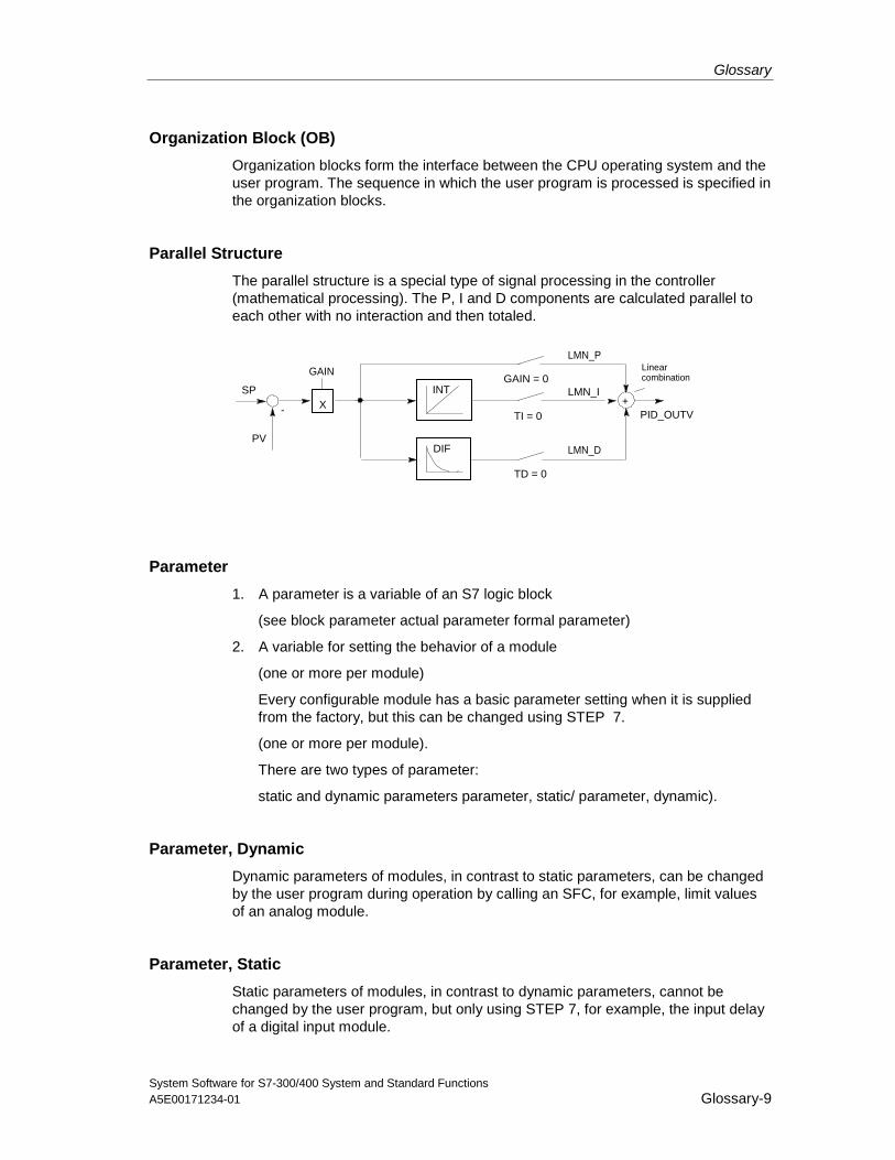
Glossary
System Software for S7-300/400 System and Standard FunctionsA5E00171234-01 Glossary-9
Organization Block (OB)
Organization blocks form the interface between the CPU operating system and theuser program. The sequence in which the user program is processed is specified inthe organization blocks.
Parallel Structure
The parallel structure is a special type of signal processing in the controller(mathematical processing). The P, I and D components are calculated parallel toeach other with no interaction and then totaled.
-
Linearcombination
LMN_ISP
PV
+TI = 0
TD = 0
GAIN = 0INT
DIF LMN_D
GAIN
X
LMN_P
PID_OUTV
Parameter
1. A parameter is a variable of an S7 logic block
(see block parameter actual parameter formal parameter)
2. A variable for setting the behavior of a module
(one or more per module)
Every configurable module has a basic parameter setting when it is suppliedfrom the factory, but this can be changed using STEP 7.
(one or more per module).
There are two types of parameter:
static and dynamic parameters parameter, static/ parameter, dynamic).
Parameter, Dynamic
Dynamic parameters of modules, in contrast to static parameters, can be changedby the user program during operation by calling an SFC, for example, limit valuesof an analog module.
Parameter, Static
Static parameters of modules, in contrast to dynamic parameters, cannot bechanged by the user program, but only using STEP 7, for example, the input delayof a digital input module.
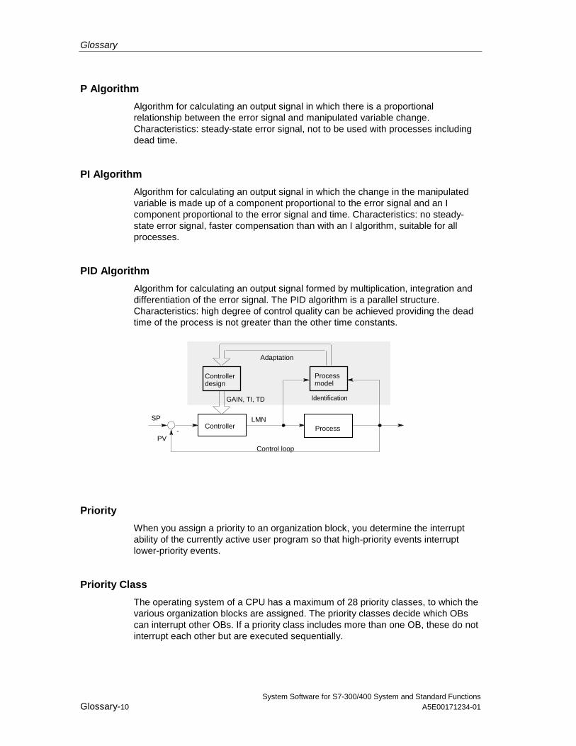
Glossary
System Software for S7-300/400 System and Standard FunctionsGlossary-10 A5E00171234-01
P Algorithm
Algorithm for calculating an output signal in which there is a proportionalrelationship between the error signal and manipulated variable change.Characteristics: steady-state error signal, not to be used with processes includingdead time.
PI Algorithm
Algorithm for calculating an output signal in which the change in the manipulatedvariable is made up of a component proportional to the error signal and an Icomponent proportional to the error signal and time. Characteristics: no steady-state error signal, faster compensation than with an I algorithm, suitable for allprocesses.
PID Algorithm
Algorithm for calculating an output signal formed by multiplication, integration anddifferentiation of the error signal. The PID algorithm is a parallel structure.Characteristics: high degree of control quality can be achieved providing the deadtime of the process is not greater than the other time constants.
-
LMNSP
PV
Controller Process
Control loop
Processmodel
Controller design
GAIN, TI, TD Identification
Adaptation
Priority
When you assign a priority to an organization block, you determine the interruptability of the currently active user program so that high-priority events interruptlower-priority events.
Priority Class
The operating system of a CPU has a maximum of 28 priority classes, to which thevarious organization blocks are assigned. The priority classes decide which OBscan interrupt other OBs. If a priority class includes more than one OB, these do notinterrupt each other but are executed sequentially.
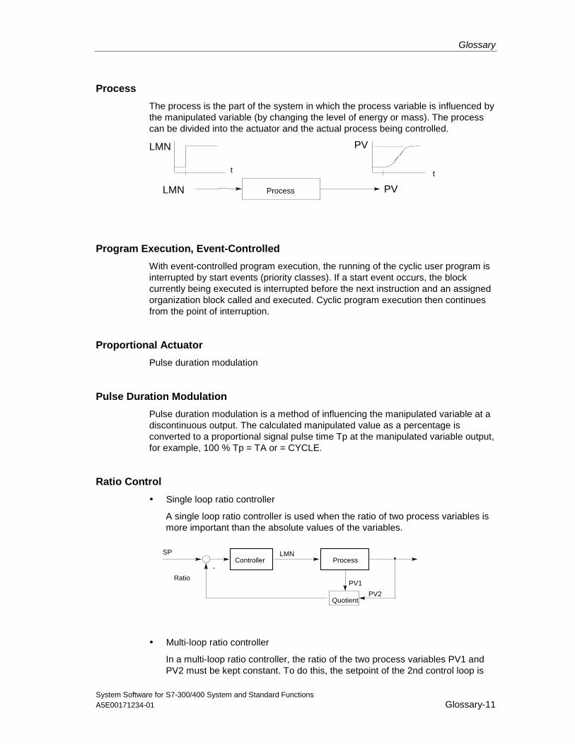
Glossary
System Software for S7-300/400 System and Standard FunctionsA5E00171234-01 Glossary-11
Process
The process is the part of the system in which the process variable is influenced bythe manipulated variable (by changing the level of energy or mass). The processcan be divided into the actuator and the actual process being controlled.
t
Process
t
LMN
PV
PV
LMN
Program Execution, Event-Controlled
With event-controlled program execution, the running of the cyclic user program isinterrupted by start events (priority classes). If a start event occurs, the blockcurrently being executed is interrupted before the next instruction and an assignedorganization block called and executed. Cyclic program execution then continuesfrom the point of interruption.
Proportional Actuator
Pulse duration modulation
Pulse Duration Modulation
Pulse duration modulation is a method of influencing the manipulated variable at adiscontinuous output. The calculated manipulated value as a percentage isconverted to a proportional signal pulse time Tp at the manipulated variable output,for example, 100 % Tp = TA or = CYCLE.
Ratio Control
• Single loop ratio controller
A single loop ratio controller is used when the ratio of two process variables ismore important than the absolute values of the variables.
SP
-
LMN
Quotient
RatioPV1
PV2
Controller Process
• Multi-loop ratio controller
In a multi-loop ratio controller, the ratio of the two process variables PV1 andPV2 must be kept constant. To do this, the setpoint of the 2nd control loop is
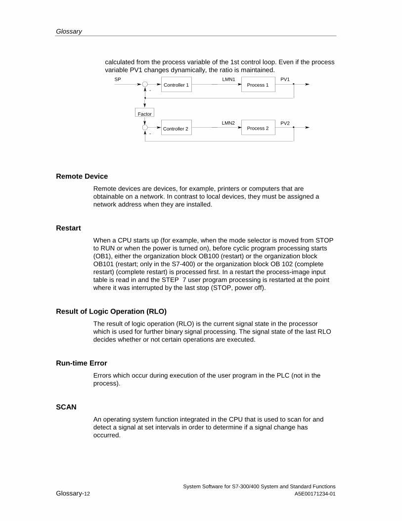
Glossary
System Software for S7-300/400 System and Standard FunctionsGlossary-12 A5E00171234-01
calculated from the process variable of the 1st control loop. Even if the processvariable PV1 changes dynamically, the ratio is maintained.
SP
-
LMN1Controller 1 Process 1
-
Factor
PV2
PV1
Process 2Controller 2LMN2
Remote Device
Remote devices are devices, for example, printers or computers that areobtainable on a network. In contrast to local devices, they must be assigned anetwork address when they are installed.
Restart
When a CPU starts up (for example, when the mode selector is moved from STOPto RUN or when the power is turned on), before cyclic program processing starts(OB1), either the organization block OB100 (restart) or the organization blockOB101 (restart; only in the S7-400) or the organization block OB 102 (completerestart) (complete restart) is processed first. In a restart the process-image inputtable is read in and the STEP 7 user program processing is restarted at the pointwhere it was interrupted by the last stop (STOP, power off).
Result of Logic Operation (RLO)
The result of logic operation (RLO) is the current signal state in the processorwhich is used for further binary signal processing. The signal state of the last RLOdecides whether or not certain operations are executed.
Run-time Error
Errors which occur during execution of the user program in the PLC (not in theprocess).
SCAN
An operating system function integrated in the CPU that is used to scan for anddetect a signal at set intervals in order to determine if a signal change hasoccurred.
Glossary
System Software for S7-300/400 System and Standard FunctionsA5E00171234-01 Glossary-13
Standard Function
Standard functions are function blocks available from SIEMENS for implementingcomplex tasks.
Standard Function Block
Standard function blocks are function blocks available from SIEMENS forimplementing complex tasks.
Start Event
Start events are defined events such as errors or interrupts which prompt theoperating system to call the appropriate organization block.
Start Event Information
The start event information is part of an organization block (OB). Start eventinformation provides the S7 user with detailed information about the event whichtriggered the call for the OB. The start event information contains the event number(consisting of event classes and event IDs), an event time stamp, and additionalinformation (for example, the address of the interrupt-activating signal module).
Start Information
When the operating system calls an organization block, the operating systemtransfers start information which can be interpreted in the user program.
Startup OB
Depending on the setting of the startup mode selector (only S7-400), the reason forthe startup (return of power after outage, manual switch from STOP to RUN withthe mode selector or command from the programming device) either the startuporganization block "Complete restart" or "Restart" (only exists on the S7-400) iscalled by the operating system. In the startup OB, the SIMATIC S7 user can, forexample, program how the system will start up again after a power outage.
An instruction (STEP 5 or STEP 7) is the smallest part of a program created in atextual language. It represents a command for the processor.
Statement List
The Statement List is the assembly language of STEP 7. When a program isprocessed in STL, the individual instructions correspond to the sequence withwhich the CPU processes the program.
STEP 7
Programming software for creating user programs for SIMATIC S7 controllers.
Glossary
System Software for S7-300/400 System and Standard FunctionsGlossary-14 A5E00171234-01
STEP 7 Programming Language
Programming language for SIMATIC S7 controllers. The S7 programmer can useSTEP 7 in different representation types: a) Statement List, b) Control SystemFlowchart, c) Ladder Logic.
Step Controller
A step controller is a quasi continuous controller with a discontinuous output (andmotor-driven actuator with an I action). The actuator has a three-step response, forexample, up - stop - down (or open - hold - close).
(Three-step controller).
STL
Statement List.
Subnumber
The number of the signal to be monitored if a message block can monitor morethan one signal.
Symbol-Related Message
A message used in configuring messages for a symbol (input, output, bit memory,data block) in the symbol table. During configuration, the time interval must be setfor the SCAN function used to monitor the signal.
Symbolic Programming
The STEP 7 programming language allows the use of symbolic names instead ofSTEP 7 addresses. For example, a STEP 7 address "Q 1.1" can be replaced with"Valve 17."
The symbol list in STEP 7 also creates the link between the address and theassigned symbolic name.
System Diagnostics
The detection and evaluation of system diagnostic events.
System Diagnostic Event
An entry which is made in the diagnostic buffer of the CPU and is used to initializeoperating system.
Glossary
System Software for S7-300/400 System and Standard FunctionsA5E00171234-01 Glossary-15
System Function (SFC)
A system function (SFC) is a function which is integrated in the CPU operatingsystem and can be called in the STEP 7 user program as required.
System Function Block (SFB)
A system function block (SFB) is a function block integrated in the CPU operatingsystem which can be called in the STEP 7 user program when required.
Three-Step Controller
A controller that can only adopt three discrete states; for example, "heat - off cool"or "right - stop - left" (step controller).
Time-Delay Interrupt
The time-delay interrupt belongs to one of the priority classes used in SIMATIC S7program processing. This interrupt is generated in the user program after aspecified time has elapsed and is processed in the associated organization block.
Tool
A software feature used for configuring and programming.
Two-step Controller
A two-step controller is a controller that can only set two states for the manipulatedvariable (for example, on - off).
User-Defined Diagnostics
The detection and evaluation of user-defined diagnostic events.
User-Defined Diagnostic Event
A diagnostic event detected by the user which can be placed into the diagnosticbuffer (with SFC 52).
User-Defined Diagnostic Message
A message reporting the occurrence of a user-defined diagnostic event.
User Program
The user program contains all the statements and declarations and the data forsignal processing with which a system or process can be controlled. It is assigned
Glossary
System Software for S7-300/400 System and Standard FunctionsGlossary-16 A5E00171234-01
to a programmable module (module, programmable) and can be structured insmaller units known as blocks.
User Program Error
Errors which may occur during the processing of the user program in a SIMATICS7 PLC (in contrast to process errors). The operating system handles errors usingerror OBs (priority class system), the status word and output parameters fromsystem functions.
Variable
A variable defines a data with variable contents that can be used in the STEP 7user program. A variable consists of an address (for example, M 3.1) and a datatype (for example, BOOL) and is represented by a symbol (for example,MOTOR_ON).
Variable Declaration
The variable declaration incorporates the entry of a symbolic name, a data typeand possibly a default value, address and comment.
System Software for S7-300/400 System and Standard FunctionsA5E00171234-01 Index-1
Index
AAborting an Existing Connection to a
Communication Partner outside theLocal S7 Station withSFC 69 "X_ABORT"...............................20-17
Aborting an Existing Connection to aCommunication Partner within theLocal S7 Station withSFC 74 "I_ABORT" ................................20-22
Access error .................................................11-1Access error filter .........................................11-4Access error filter for the CPU 417 and
CPU 417H ................................................11-1Access errors with the CPU 417 and
CPU 417H: ...............................................11-1ACCFLT_ESR............................................11-11ACCFLT_MASKED ...........................11-9, 11-10ACCFLT_QUERY.......................................11-11ACCFLT_RESET_MASK ...........................11-10ACCFLT_SET_MASK ..................................11-9ACT_TINT ......................................................9-6Activating a Time-of-Day Interrupt with
SFC 30 "ACT_TINT" ..................................9-6AD_DT_TM ..................................................23-6ADC/DAC error.............................................29-2Additional Error Information of the
SFBs 60 to 65.........................................25-58ALARM:......................................................21-10ALARM_8:..................................................21-16ALARM_8P: ...............................................21-13ALARM_D ..................................................21-32ALARM_DQ................................................21-32ALARM_S: .................................................21-28ALARM_SC................................................21-31ALARM_SQ................................................21-28Alignment error....................................11-6, 11-7
when reading............................................11-1when writing .............................................11-1
AR_SEND: .................................................21-18Area error .....................................................11-6
when reading............................................11-1when writing .............................................11-1
Area length error ..........................................11-6when reading............................................11-1when writing .............................................11-1
Assembly Code BlockCalling ......................................................28-1
Assigning Parameters to a Module withSFC 57 "PARM_MOD"...............................7-8
Asynchronous error .........12-1, 12-3, 12-4, 12-5,........................................................ 12-6, 12-7delaying with SFC 41 DIS_AIRT.............. 12-6disabling with SFC 39 DIS_IRT ............... 12-3enabling with SFC 40 EN_IRT ................. 12-5enabling with SFC 42 EN_AIRT............... 12-7
Asynchronous error: .................................... 31-4Asynchronous errors.................................... 1-28
OB80........................................................ 1-28
BBackground Organization Block (OB90) ...... 1-50Battery backup............................................. 29-2
failed ........................................................ 29-2Battery exhausted........................................ 29-2BCD conversion error .................................. 11-6Bit field in the I/O area ................................. 14-8
setting with SFC 79.................................. 14-8BLK................................................................ 3-6BLKMOV........................................................ 3-1Block number error ...................................... 11-7Block types: ............................................... 30-13BRCV......................................................... 19-21BSEND ...................................................... 19-17BVAL ............................................................. 3-5
CC_DIAG ..................................................... 13-17Calling an Assembly Code Block: ................ 28-1CAN_DINT................................................... 10-5CAN_TINT ..................................................... 9-5Canceling a Time-Delay Interrupt with
SFC 33 "CAN_DINT" ............................... 10-5Canceling a Time-of-Day Interrupt with
SFC 29 "CAN_TINT".................................. 9-5CDT ............................................................... 5-2Changing a Remote Device to the
STOP State with SFB 20 "STOP" .......... 19-36Changing the CPU to STOP with
SFC 46 "STP" ............................................ 4-1Channel .............................................. 29-2, 29-3
error ......................................................... 29-2information ............................................... 29-2
Characteristics of SFCs 28 to 31 ................... 9-2CiR.......................................................... 4-4, 4-5CiR Operation .............................................. 1-35Classification and Work Memory Requirements
of the S7 Communication SFBs............... 18-5Clearing The Input Buffer........................... 25-42Clock
Index
System Software for S7-300/400 System and Standard FunctionsIndex-2 A5E00171234-01
Master: ....................................................... 5-1Synchronization: ........................................ 5-1
Clock:............................................................. 5-1Common mode error.................................... 29-4
analog input module................................. 29-4analog output module .............................. 29-4
Common Parameters of the CommunicationSFCs: ....................................................... 20-1
Common Parameters of the SFBs/FBsand SFCs/FCs for S7 Communication ..... 19-1
Communication................................. 12-2, 30-24error: ........................................................ 12-1interrupt.................................................... 12-2status data: ............................................ 30-24
Communication Error Organization Block(OB87) ..................................................... 1-47
Communication events: ............................. 31-10Communication Redundancy Error OB
(OB73) ..................................................... 1-27Communication SFCs............18-9, 18-10, 18-11Communication SFCs for non-configured S7
connections........................18-9, 18-10, 18-11classification:............................................ 18-8
Comparing DATE_AND_TIME Variables.....................................................23-10, 23-11, 23-12
Comparing STRING Variables....... 23-13, 23-14,............................................................... 23-15
Complete restart ....................1-52, 19-34, 19-35Component Identification ........................... 30-16COMPRESS: ............................................... 3-12Compressing the User Memory with
SFC 25 "COMPRESS"............................. 3-12CONCAT.................................................... 23-19Configuration ............................................... 29-4
erroranalog input module............................. 29-4analog output module .......................... 29-4digital input module .............................. 29-4
Connection.....13-17, 13-18, 13-19, 13-20, 13-21diagnostics with SFC 87 ........................ 13-17
CONT_C ...................................................... 24-4CONT_S ...................................................... 24-9Continuous Control with SFB 41/FB 41
"CONT_C"................................................ 24-1Control ........24-1, 24-5, 24-7, 24-9, 24-10, 24-13
continuous control with SFB 41................ 24-1step control with SFB 42 .......................... 24-9
CONTROL ................................................. 19-45Controlling CiR with SFC 104 "CiR"............... 4-4Controlling Operation in H Systems with
SFC 90 "H_CTRL" ................................... 26-1Controlling Operation in H Systems with
SFC 90:.................................................... 26-1Controlling Positioning With Analog Output
Via User Program .................................... 25-1Controlling positioning with digital output
with the user program ............................ 25-13Controlling Pulse Width Modulation
Via User Program .................................. 25-33Controlling the Counter via User Program . 25-24
Controlling The Frequency MeasurementVia User Program...................................25-29
Converting Data Type Formats ......23-24, 23-25,...............................................................23-26
Copying variables...........................................3-1with SFC 20 BLKMOV................................3-2
Copying Variables with SFC 20 "BLKMOV" ...3-1COUNT...........................................................3-7Count down: .................................................22-8Count up:......................................................22-7Counter (CPU 312).......................................27-1Counters.......................................................11-6
number error.............................................11-6Counting Down with SFB 1 "CTD"................22-8Counting Up with SFB 0 "CTU" ....................22-7CPU........................... 4-1, 12-1, 12-2, 30-7, 30-8
changing to the STOP mode withSFC 46 STP: ..........................................4-1
characteristics: .........................................30-7hardware fault...........................................12-2
CPU hardware fault OB................................1-38CPU Hardware Fault Organization Block
(OB84)......................................................1-38CPU Redundancy Error OB (OB72) .............1-24CQ..................................................................6-6CREA_DBL ..................................................3-15CREATE_DB..................................................3-7Creating a Data Block with SFC 22
"CREAT_DB"..............................................3-7CTD..............................................................22-8CTRL_RTM ....................................................6-5CTU..............................................................22-7CTUD ...........................................................22-9Current below measuring range ...................29-4
analog input module .................................29-4CV ..................................................................6-6Cycle time monitoring...................................29-2Cyclic Interrupt Organization Blocks
(OB30 to OB38)........................................1-12Cyclic interrupts...................................1-12, 12-2
OB35 ...............................................1-12, 1-13
DD_TOD_DT ..................................................23-6Data block ..................................... 3-7, 3-9, 3-20
creating with SFC 22 CREAT_DB ..............3-7deleting with SFC 23 ..................................3-9
Data Block....................................................3-18Reading from a Data Block in Load Memory
with SFC 83 "READ_DBL" ...................3-18Data Consistency with GET and
PUT SFCs: ...............................................18-3Data record................. 7-1, 7-2, 7-11, 7-12, 7-13,
.............................................. 7-14, 7-15, 7-16reading .......................................................7-1reading with SFC 59 RD_REC .................7-12writing.........................................................7-1writing with SFC 58 WR_REC..................7-11
Data Record ............................. 8-1, 8-2, 8-3, 8-4
Index
System Software for S7-300/400 System and Standard FunctionsA5E00171234-01 Index-3
reading from a DP Slave withSFB 52 RDREC......................................8-1
Writing in a DP Slave withSFB 53 WRREC.....................................8-3
Data record of the Partial List Extractwith SSL ID W#16#0132 andIndex W#16#000B..................................30-28
Data record of the Partial List Extractwith SSL ID W#16#0132 andIndex W#16#000C..................................30-29
Data Record of the Partial List Extractwith SSL-ID W#16#0132Index W#16#0005: .................................30-25
Data Record of the Partial List Extractwith SSL-ID W#16#0132Index W#16#0008: .................................30-26
Data Record of the Partial List Extractwith SSL-ID W#16#0232Index W#16#0004: .................................30-30
Date and Time as Complex Data Types.......23-5Date:...............................................................5-1DB_NUMBER.................................................3-7Deactivating and Activating DP Slaves
with SFC 12 "D_ACT_DP"......................16-10DEL_DB .........................................................3-9DEL_SI.......................................................21-37Delay time: ...................................................10-1Delaying and Disabling Interrupts and
Asynchronous Errors................................12-1Delaying Execution of the User Program
with SFC 47 "WAIT" ...................................4-2Delaying the Processing of Higher Priority
Interrupts and Asynchronous Errorswith SFC 41 "DIS_AIRT" ..........................12-6
Delaying the user program .............................4-2with SFC 47 WAIT......................................4-2
DELETE .....................................................23-19Deleting a Data Block with
SFC 23 "DEL_DB"......................................3-9Determining the OB Program Run Time
with SFC 78 "OB_RT" ............................13-14DI_STRNG .................................................23-24Diagnosis of the Current Connection Status
with SFC 87 "C_DIAG"...........................13-17Diagnostic buffer ..........................................11-1Diagnostic buffer: ..............................30-1, 30-50Diagnostic data .................. 7-2, 29-1, 30-1, 30-2
content: ....................................................29-1of the CPU................................................30-1of the signal modules ...............................30-1of the signal modules: ................................7-1structure ...................................................29-1
Diagnostic Data............................................29-2Diagnostic data of a module.........................29-1Diagnostic events: ......................................31-13Diagnostic interrupt .............................12-2, 29-2
from substitute..........................................29-2Diagnostic Interrupt Organization Block
(OB82)......................................................1-33Diagnostics with SFC 87 ............................13-17
Differences between the Blocks of the S7Communication and the S7 BasicCommunication........................................ 18-1
DIS_AIRT..................................................... 12-6DIS_IRT....................................................... 12-3DIS_MSG:.................................................. 21-20Disabling the Processing of New Interrupts
and Asynchronous Errors withSFC 39 "DIS_IRT" ................................... 12-3
DMSK_FLT................................................ 11-10DP Master System Information .................. 30-38DP_PRAL .................................................... 16-1DP_TOPOL................................................ 13-22DPNRM_DG: ............................................. 16-15DPRD_DAT: .............................................. 16-19DPSYC_FR:................................................. 16-3DPWR_DAT:.............................................. 16-21DRUM........................................................ 14-11DSTBLK......................................................... 3-2DT_DATE .................................................... 23-7DT_DAY....................................................... 23-7DT_TOD ...................................................... 23-8DTIME.......................................................... 10-3
EEditing Number Values ........ 23-16, 23-17, 23-18Editing STRING Variables ............. 23-19, 23-20,
......................................... 23-21, 23-22, 23-23EN_AIRT...................................................... 12-7EN_IRT........................................................ 12-5EN_MSG:................................................... 21-22Enabling Block-Related
Symbol-Relatedand Group Status Messages with
SFC 9 "EN_MSG" .......................... 21-22Enabling the Processing of Higher Priority
Interrupts and Asynchronous Errorswith SFC 42 "EN_AIRT"........................... 12-7
Enabling the Processing of New Interruptsand Asynchronous Errors withSFC 40 "EN_IRT" .................................... 12-5
EQ_DT....................................................... 23-10EQ_STRNG............................................... 23-13Error...............11-1, 11-2, 11-3, 11-4, 11-5, 11-6,
.............................11-7, 11-8, 12-2, 29-2, 29-3access..................11-1, 11-2, 11-4, 11-5, 11-8ADC/DAC................................................. 29-2asynchronous .......................................... 12-1EPROM.................................................... 29-2masking ................................................... 11-1programming........11-1, 11-2, 11-3, 11-6, 11-7RAM......................................................... 29-2synchronous ................................... 11-1, 11-2
Error detection ..................1-12, 1-28, 1-57, 1-60types of OB
OB121.................................................. 1-57OB122.................................................. 1-60OB35.................................................... 1-12OB80.................................................... 1-28
Index
System Software for S7-300/400 System and Standard FunctionsIndex-4 A5E00171234-01
Error filter ................11-2, 11-3, 11-4, 11-5, 11-6,........................................................ 11-7, 11-8access errors .......11-1, 11-2, 11-4, 11-5, 11-8programming errors ......11-1, 11-3, 11-6, 11-7
Error handling .............................................. 11-1Error information ..................3-8, 3-9, 3-10, 10-4,
........................................................ 12-5, 12-7SFC 22 CREAT_DB:.................................. 3-7SFC 23 DEL_DB:....................................... 3-9SFC 34 QRY_DINT:................................. 10-4SFC 40 EN_IRT: ...................................... 12-5SFC 42 EN_AIRT:.................................... 12-7
Error Information of the CommunicationSFCs for Non-ConfiguredS7 Connections:....................................... 20-3
Error interrupt............................................... 12-1asynchronous.................................. 12-1, 12-2synchronous............................................. 12-2
Error OB..................1-12, 1-28, 1-31, 1-33, 1-39,........................................................ 11-1, 11-2types of OB
OB35.................................................... 1-12OB80........................................... 1-28, 1-29OB81.................................................... 1-31OB82.................................................... 1-33OB85.........................1-39, 1-40, 1-41, 1-42
Error register............................11-1, 11-2, 11-11reading with SFC 38 READ_ERR.......... 11-11
Evaluating Errors with the Output ParameterRET_VAL................................................... 2-1
Event.......13-10, 13-11, 13-12, 13-13, 31-1, 31-2class:........................................................ 31-1ID13-11, 13-12, 31-1, 31-2
Event Class 1 - Standard OB Events ........... 31-2Event Class 2 - Synchronous Errors ............ 31-3Event Class 3 - Asynchronous Errors .......... 31-4Event Class 4 - Stop Events and
Other Mode Changes............................... 31-6Event Class 5 - Mode Runtime Events: ....... 31-9Event Class 6 - Communication Events..... 31-10Event Class 7 - H/F Events........................ 31-11Event Class 8 - Diagnostic Events
for Modules ............................................ 31-13Event Class 9 - Standard User Events....... 31-15Event Classes A and B - Free
User Events ........................................... 31-17EVENTN .................................................... 13-10Events and Event ID .................................... 31-1Example of the PULSEGEN Block:............ 24-25Expansion rack failure.................................. 29-2External error ............................................... 29-2
FFB 12 BSEND............................................ 19-15FB 13 BRCV .............................................. 19-18FB 15 PUT ................................................. 19-22FB 8 USEND................................................ 19-9FB 9 URCV ................................................ 19-12FC1 .............................................................. 23-6
FC10 ..........................................................23-13FC11 ..........................................................23-20FC12 ..........................................................23-10FC13 ..........................................................23-13FC14 ..........................................................23-11FC15 ..........................................................23-14FC16 ..........................................................23-24FC17 ..........................................................23-20FC18 ..........................................................23-11FC19 ..........................................................23-14FC2 ............................................................23-19FC20 ..........................................................23-21FC21 ..........................................................23-21FC22 ..........................................................23-16FC23 ..........................................................23-12FC24 ..........................................................23-15FC25 ..........................................................23-16FC26 ..........................................................23-22FC27 ..........................................................23-17FC28 ..........................................................23-12FC29 ..........................................................23-15FC3 ..............................................................23-6FC30 ..........................................................23-25FC31 ..........................................................23-22FC32 ..........................................................23-23FC33 ............................................................23-8FC34 ............................................................23-8FC35 ............................................................23-9FC36 ..........................................................23-18FC37 ..........................................................23-25FC38 ..........................................................23-26FC39 ..........................................................23-26FC4 ............................................................23-19FC5 ............................................................23-24FC6 ..............................................................23-7FC7 ..............................................................23-7FC8 ..............................................................23-8FC9 ............................................................23-10FILL ................................................................3-5Filter .............................................................11-1
errors .................. 11-1, 11-2, 11-4, 11-5, 11-6,....................................................11-7, 11-8
FIND...........................................................23-20Free user events: .......................................31-17Frequency Meter (CPU 312) ........................27-2Further Error Information for
SFCs 55 to 59: .........................................7-17Fuse tripped .................................................29-2
GGADR_LGC:.................................................15-1GD packet ............... 17-1, 17-2, 17-3, 17-4, 17-5
Programmed Acceptance with SFC 61 ....17-3sending with SFC 60 ................................17-1
GD_RCV ......................................................17-3GD_SND: .....................................................17-1GE_DT .......................................................23-10GE_STRNG................................................23-13Generating a Data Block ..............................3-15
Index
System Software for S7-300/400 System and Standard FunctionsA5E00171234-01 Index-5
with SFC82 "CREA_DBL..........................3-15Generating a Data Block in the Load Memory
with SFC82 "CREA_DBL" ........................3-15Generating a Pulse with SFB 3 "TP" ............22-1Generating Acknowledgeable and
Permanently AcknowledgedBlock Related Messages withSFC 107 "ALARM_DQ"..........................21-32
Generating Acknowledgeable andPermanently AcknowledgedBlock Related Messages withSFC 108 "ALARM_D".............................21-32
Generating Acknowledgeable Block-RelatedMessages with SFC 17 "ALARM_SQ" andPermanently Acknowledged Block-RelatedMessages with SFC 18 "ALARM_S" ......21-28
Generating an Off Delay with SFB 5 "TOF"..22-5Generating an On Delay with SFB 4 "TON" .22-3Generating Block Related Messages without
Acknowledgement Display withSFB 31 "NOTIFY_8P" ..............................21-7
Generating Block-Related Messages withAccompanying Values for Eight Signalswith SFB 35 "ALARM_8P"......................21-13
Generating Block-Related Messages withAcknowledgment withSFB 33 "ALARM" ...................................21-10
Generating Block-Related Messages withoutAcknowledgment with SFB 36 "NOTIFY" .21-5
Generating Block-Related Messages withoutAssociated Values for Eight Signalswith SFB 34 "ALARM_8" ........................21-16
GET............................................................19-25Ground error.................................................29-5
digital input module ..................................29-4Groups of DP slaves ....................................16-3
synchronizing ...........................................16-3GT_DT .......................................................23-11GT_STRNG................................................23-14
HH/F events:.................................................31-11H_CTRL .......................................................26-1Handling Runtime meters with
SFC 101 "RTM"..........................................6-2Handling Time-Delay Interrupts....................10-1Handling Time-of-Day Interrupts ....................9-1Hardware interrupt...............................12-1, 29-2
lost:...........................................................29-2Hardware interrupt OBs................................1-14Hardware Interrupt Organization Blocks
(OB40 to OB47)........................................1-14How SFBs for S7 Communication React
to Problems ..............................................19-7How the SFBs for Generating Block-Related
Messages React to Problems:................21-24
II/O access error ........................................... 11-8
when reading .................................. 11-6, 11-8when writing........................... 11-6, 11-7, 11-8
I/O Access Error Organization Block(OB122) ................................................... 1-60
I/O Redundancy Error OB (OB70) ............... 1-22I_ABORT: .................................................. 20-22I_GET: ....................................................... 20-20I_PUT: ....................................................... 20-18I_STRNG ................................................... 23-24Identifying the Bus Topology of a
DP Master System................................. 13-22Implementing a Sequencer with
SFB 32 "DRUM" .................................... 14-10INFO1 ........................................................ 13-10INFO2 ............................................. 13-12, 13-13Initializing a memory area.............................. 3-5
with SFC 21 FILL ....................................... 3-5Initializing a Memory Area with
SFC 21 "FILL"............................................ 3-5Initiating a Hot Restart on a Remote Device
with SFB 21 "RESUME"......................... 19-38Initiating a Warm or Cold Restart on a
Remote Device with SFB 19 "START"... 19-34INSERT...................................................... 23-20Insert/Remove OB (OB 83).......................... 1-35Integrated Counter Function: ....................... 27-1Integrated Frequency Meter Function:......... 27-2Internal error ................................................ 29-2Interrupt ..................1-10, 1-11, 1-12, 1-13, 1-16,
....................12-1, 12-3, 12-4, 12-5, 12-6, 12-7classes............................................ 12-1, 12-2cyclic (OB35): .......................................... 1-12delaying with SFC 41 DIS_AIRT.............. 12-6disabling with SFC 39 DIS_IRT ............... 12-3DPV1 Interrupt ......................................... 1-16enabling with SFC 40 EN_IRT ................. 12-5enabling with SFC 42 EN_AIRT............... 12-7
Interrupt Class ............................................. 1-35Interrupt OBs ............................................... 1-33
diagnostic interrupts:................................ 1-33time-of-day interrupts................................. 1-7
Interrupt status........................................... 30-19Interrupts...........1-6, 1-14, 1-15, 1-17, 1-18, 1-35
DPV1 Interrupt ......................................... 1-17DPV1-Interrupt......................................... 1-18hardware interrupt OBs................... 1-14, 1-15Insert/Remove Interrupt ........................... 1-35Manufacturer specific interrupt................. 1-18Status Interrupt ........................................ 1-16time-delay ....................................... 1-10, 1-11Update Interrupt....................................... 1-17
Introduction to Generating Block-RelatedMessages with SFBs: .............................. 21-1
Introduction to Generating Block-RelatedMessages with SFCs: ............................ 21-25
IOID ...............................7-5, 7-7, 7-8, 7-11, 7-12
Index
System Software for S7-300/400 System and Standard FunctionsIndex-6 A5E00171234-01
LLADDR................... 7-5, 7-7, 7-8, 7-9, 7-11, 7-12LE_DT........................................................ 23-11LE_STRNG................................................ 23-14LEFT .......................................................... 23-21LEN............................................................ 23-21LGC_GADR ................................................. 15-2LIMIT.......................................................... 23-16List of SFBs
Sorted Alphabetically: .............................. 32-9Sorted Numerically:.................................. 32-7
List of SFCsSorted Alphabetically: .............................. 32-4Sorted Numerically:.................................. 32-1
Local data of the OBs: ............................... 30-34Logical address................................... 15-1, 15-4
of a channelquerying ............................................... 15-1
of a modulequerying all addresses ......................... 15-4
LOW_LIMIT ................................................... 3-7LT_DT........................................................ 23-12LT_STRNG ................................................ 23-15
MM short circuit...................................... 29-4, 29-5
analog input module................................. 29-4analog output module .............................. 29-4
Manufacturer specific Interrupt .................... 1-18Masking ....................................................... 11-1
errors ....................................................... 11-1Masking Synchronous Errors....................... 11-1Masking Synchronous Errors with
SFC 36 "MSK_FLT" ................................. 11-9Master clock:.................................................. 5-1MAX ........................................................... 23-16Meaning of the Parameters REQ
RET_VAL and BUSY with AsynchronousSFCs...................................................... 2-6
Measuring range exceeded ......................... 29-4analog input module................................. 29-4
Memory areas: ........................................... 30-10Memory card ................................................ 29-2MID ............................................................ 23-22MIN ............................................................ 23-17MODE ................................................. 12-3, 12-5Mode changes ............................................. 31-6Module ..............................29-2, 29-3, 30-4, 30-6
fault .......................................................... 29-2identification: ............................................ 30-6type ID ..................................................... 30-4
Module diagnostic data .............................. 30-53Module diagnostic data: ............................. 30-54Module diagnostic information: .................. 30-51Module slot .................................................. 15-2
of a logical addressquerying ............................................... 15-2
Module status information:......................... 30-40
MP_ALM.........................................................4-3MSK_FLT .....................................................11-9Multicomputing interrupt ...............................12-2Multicomputing Interrupt Organization Block
(OB60)......................................................1-19
NNE_DT........................................................23-12NE_STRNG................................................23-15No auxiliary voltage ......................................29-2No front connector........................................29-2No load voltage ...................................29-4, 29-5
analog output module...............................29-4No parameter assignment ............................29-2NOTIFY: .......................................................21-5NOTIFY_8P..................................................21-7NR ................................................... 6-4, 6-5, 6-6
OOB 10 to OB 17 ..............................................1-6OB 20 to OB 23 ............................................1-10OB 55 ...........................................................1-16OB 56 ...........................................................1-17OB 73 ...........................................................1-27OB 83 ..................................................1-35, 1-36OB 88 ...........................................................1-49OB for manufacturer specific interrupts
(OB57)......................................................1-18OB)...............................................................1-35OB_NR.........9-4, 9-5, 9-6, 9-7, 10-3, 10-4, 10-5,
.............................................. 12-3, 12-4, 12-5OB100
OB101and OB102 ...........................................1-52
OB121 .................................................1-57, 1-60OB30 to OB38..............................................1-12OB40 to OB47..............................................1-14OB57 ............................................................1-18OB60 ...................................................1-19, 1-20OB60: .............................................................4-3OB70 ............................................................1-22OB72 ...................................................1-24, 1-26OB80 ............................................................1-28OB81 ............................................................1-31OB82 ............................................................1-33OB84 ............................................................1-38OB85 ............................................................1-39OB86 ......................................... 1-43, 1-44, 1-45OB87 ............................................................1-47Off delay.......................................................22-5
generating: ...............................................22-5On delay.......................................................22-3
generating: ...............................................22-3Organisation blocks (OBs)..............................1-6
time-of-day interrupt OBs(OB10 bis OB17) ....................................1-6
Index
System Software for S7-300/400 System and Standard FunctionsA5E00171234-01 Index-7
Organization block (OB) .....................1-10, 1-12,........................... 1-16, 1-17, 1-18, 1-19, 1-28,..........1-31, 1-33, 1-39, 1-49, 1-50, 1-57, 1-60background OB (OB90)............................1-50multicomputing interrupt OB (OB60) ........1-19OB for manufacturer specific interrupts
(OB57)..................................................1-18OB121: .....................................................1-57OB122 ......................................................1-60Processing Interrupt OB (OB 88)..............1-49Status Interrupt OB (OB 55) .....................1-16Time-delay interrupt OBs
(OB20 to OB23)....................................1-10types of
OB35 ....................................................1-12OB80 ....................................................1-28OB81 ....................................................1-31OB82 ....................................................1-33OB85 ....................................................1-39
Update Interrupt OB (OB 56)....................1-17Organization Block (OB)...............................1-35
Insert/Remove OB (OB83) .......................1-35Organization blocks (OBs)..................1-33, 1-38,
..................................... 1-39, 1-43, 1-47, 1-52communication error OB (OB87) ..............1-47complete restart OB (OB100)...................1-52CPU hardware fault OB (OB84) ...............1-38diagnostic interrupt OB (OB82) ................1-33priority class error OB (OB85) ..................1-39rack failure OB (OB86) .............................1-43restart OB (OB101) ..................................1-52startup OBs (OBs 100 and 101) ...............1-52
Overview .............................................18-8, 23-1Overview of the Organization Blocks (OBs) ...1-1Overview of the Structure of
Diagnostic Data ........................................29-1Overview of the System Status Lists (SSL)..30-1
PP sh ..............................................................29-4P short circuit ......................................29-4, 29-5
analog input module .................................29-4analog output module...............................29-4
Parameter ..........2-8, 3-1, 3-2, 3-6, 3-7, 3-8, 4-2,................5-2, 6-4, 6-5, 6-6, 7-5, 7-6, 7-7, 7-8,........7-11, 7-12, 7-13, 7-15, 9-4, 9-5, 9-6, 9-7,.............. 10-3, 10-4, 10-5, 11-9, 11-10, 11-11,.. 12-3, 12-4, 12-5, 13-10, 13-11, 13-12, 13-13ACCFLT_ESR: .......................................11-11ACCFLT_Masked:..................................11-10ACCFLT_MASKED: .................................11-9ACCFLT_QUERY...................................11-11ACCFLT_RESET_MASK .......................11-10ACCFLT_SET_MASK ..............................11-9BLK: ...........................................................3-5BUSY with SFCs 51 and 55 to 59 ..............2-6BVAL ...................................................3-5, 3-6CDT:...........................................................5-2COUNT.......................................................3-7
CQ ............................................................. 6-6CV.............................................................. 6-6DB_NUMBER ............................................ 3-7DSTBLK:.................................................... 3-1DTIME...................................................... 10-3EVENTN ..................................... 13-12, 13-13INFO1 ......................................... 13-12, 13-13INFO2: ................................................... 13-10IOID .......... 7-5, 7-7, 7-8, 7-9, 7-11, 7-12, 7-15LADDR.....................7-5, 7-7, 7-11, 7-12, 7-15LADDR:...................................................... 7-8LOW_LIMIT ............................................... 3-7MODE.................................... 12-3, 12-4, 12-5NR................................................6-4, 6-5, 6-6OB_NR ....................9-4, 9-7, 10-3, 10-4, 12-5OB_NR: ............................9-5, 9-6, 10-5, 12-3PERIOD: .................................................... 9-4PRGFLT_ESR ....................................... 11-11PRGFLT_MASKED....................... 11-9, 11-10PRGFLT_QUERY.................................. 11-11PRGFLT_RESET_MASK....................... 11-10PRGFLT_SET_MASK.............................. 11-9PV:............................................................. 6-4RECNUM ................................. 7-5, 7-11, 7-12RECNUM: .................................................. 7-7RECORD: ......................................... 7-5, 7-11REQ with asynchronous SFCs .................. 2-6RET_VAL with SFCs 51 and 55 to 59:....... 2-6SDT............................................................ 9-4SEND............................... 13-10, 13-11, 13-12SRCBLK .................................................... 3-2STATUS................................................... 10-4STATUS:.................................................... 9-7UP_LIMIT................................................... 3-7write default parameter .............................. 7-7WT: ............................................................ 4-2
Parameter assignment error ........................ 29-4analog input module ................................ 29-4analog output module .............................. 29-4digital input module.................................. 29-4
Parameters ......................5-2, 6-7, 7-1, 7-2, 7-11of the signal modules................................. 7-1SFC 1 READ_CLK..................................... 5-2SFC 58 WR_REC .................................... 7-11SFC 64 TIME_TICK:.................................. 6-7
PARM_MOD .................................................. 7-8PERIOD......................................................... 9-4Possible Partial System Status Lists............ 30-5Power supply ............................................... 29-2
failed ........................................................ 29-2Power supply error....................................... 12-2Power Supply Error Organization Block
(OB81) ..................................................... 1-31PRGFLT_ESR ........................................... 11-11PRGFLT_MASKED .......................... 11-9, 11-10PRGFLT_QUERY...................................... 11-11PRGFLT_RESET_MASK........................... 11-10PRGFLT_SET_MASK ................................. 11-9PRINT........................................................ 19-32Priority class .............1-9, 1-10, 1-12, 1-24, 1-29,
.........1-31, 1-33, 1-39, 1-49, 1-57, 1-60, 11-11
Index
System Software for S7-300/400 System and Standard FunctionsIndex-8 A5E00171234-01
types of OBOB121.................................................. 1-57OB122.................................................. 1-60OB35.................................................... 1-12OB80.................................................... 1-28OB81.................................................... 1-31OB82.................................................... 1-33OB85.................................................... 1-39
Priority class error OB.................................. 1-39Priority Class Error Organization Block
(OB85) ..................................................... 1-39Priority class:...........1-14, 1-19, 1-22, 1-38, 1-43,
................. 1-47, 1-50, 1-52, 13-1, 30-19, 31-6Processing Interrupt OB (OB 88) ................. 1-49Processor failure.......................................... 29-2Program error .............................................. 12-2Programmed Acceptance of a Received GD
Packet with SFC 61 "GD_RCV" ............... 17-3Programming ..........1-12, 1-28, 1-31, 1-33, 1-39,
........................................................ 1-57, 1-60types of OB
OB121.................................................. 1-57OB122.................................................. 1-60OB35.................................................... 1-12OB80:................................................... 1-28OB81:................................................... 1-31OB82.................................................... 1-33OB85:................................................... 1-39
Programming error....................................... 11-1Programming error filter ............................... 11-1Programming Error Organization Block
(OB121) ................................................... 1-57Pulse................................................... 22-1, 22-2
generating: ............................................... 22-1Pulse duration modulation ...24-15, 24-16, 24-23Pulse Generation with
SFB 43 "PULSEGEN"............................ 24-15PULSEGEN .........................24-15, 24-16, 24-21PUT............................................................ 19-22PV.................................................................. 6-4
QQRY_DINT................................................... 10-4QRY_TINT ..................................................... 9-7Querying a Time-Delay Interrupt with
SFC 34 "QRY_DINT" ............................... 10-4Querying a Time-of-Day Interrupt with
SFC 31 "QRY_TINT" ................................. 9-7Querying all Logical Addresses of a Module
with SFC 50 "RD_LGADR" ...................... 15-4Querying the Acknowledgment Status
of the Last ALARM_SQ Entering EventMessage with SFC 19 "ALARM_SC" ..... 21-31
Querying the Logical Base Addressof a Module with SFC 5 "GADR_LGC" .... 15-1
Querying the Module Slot Belongingto a Logical Address withSFC 49 "LGC_GADR".............................. 15-2
Querying the Status of a Remote Partner withSFB 22 "STATUS"..................................19-40
Querying the Status of the ConnectionBelonging to a SFB Instance with SFC 62"CONTROL" ...........................................19-45
RR_STRNG ..................................................23-25Rack failure ............................... 1-43, 1-44, 12-2Rack Failure Organization Block (OB86)......1-43RALRM...........................................................8-5RAM error.....................................................29-2RD_DPARA....................................................7-4RD_LGADR:.................................................15-4RD_REC.......................................................7-12RD_SINFO ...................................................13-1RDREC...........................................................8-1RDSYSST ...........................................13-4, 30-1RE_TRIGR .....................................................4-1Read Data from a Remote CPU
with SFB/FB 14 "GET"............................19-25READ_CLK ....................................................5-2READ_DBL ..................................................3-18READ_ERR................................................11-11READ_RTM....................................................6-6READ_SI ....................................................21-34Reading................................. 13-4, 16-18, 16-19
consistent data of a DP slave .................16-19diagnostic data of a DP slave .................16-15with SFC 51 RDSYSST............................13-4
Reading a Data Record from a DP Slavewith SFB 52 "RDREC"................................8-1
Reading a Data Record withSFC 59 "RD_REC"...................................7-12
Reading a Runtime Meter withSFC 4 "READ_RTM" ..................................6-6
Reading a System Status List or Partial Listwith SFC 51 "RDSYSST" .........................13-4
Reading Consistent Data of a DP StandardSlave with SFC 14 "DPRD_DAT" ...........16-19
Reading Data from a Communication Partneroutside the Local S7 Station withSFC 67 "X_GET"....................................20-15
Reading Data from a Communication Partnerwithin the Local S7 Station withSFC 72 "I_GET" .....................................20-20
Reading data from a remote CPU withSFB/FB 14:.............................................19-25
Reading Defined Parameters withSFC 54 "RD_DPARM":...............................7-3
Reading Diagnostic Data of a DP Slavewith SFC 13 "DPNRM_DG"(Slave Diagnostics).................................16-15
Reading Dynamic System Resourceswith SFC 105 "READ_SI" .......................21-34
Reading from a Data Block in Load Memorywith SFC 83 "READ_DBL" .......................3-18
Reading OB start information with SFC 6.....13-1
Index
System Software for S7-300/400 System and Standard FunctionsA5E00171234-01 Index-9
Reading OB Start Information withSFC 6 "RD_SINFO" .................................13-1
Reading Predefined Parameters withSFC 102 "RD_DPARA" ..............................7-4
Reading the Error Register withSFC 38 "READ_ERR" ............................11-11
Reading the system status ...........................13-4with SFC 51 RDSYSST............................13-4
Reading the system time................................6-7with SFC 64 TIME_TCK .............................6-7
Reading the System Time with SFC 64"TIME_TCK" ...............................................6-7
Reading the time ............................................5-2with SFC 1 READ_CLK..............................5-2
Reading the Time with SFC 1 "READ_CLK" ..5-2Receiving an Interrupt from a DP Slave with
SFB 54 "RALRM" .......................................8-5Receiving Data From A Communication partner
And Filing Them In A Data Block...........25-39Receiving data from a communication partner
and storing them in a data block(RK 512).................................................25-53
Receiving Data from a Communication Partneroutside the Local S7 Station withSFC 66 "X_RCV"......................................20-9
Receiving segmented data.........................19-18with FB 13 ..............................................19-18with SFB 13............................................19-18
Receiving Segmented Data withSFB/FB 13 "BRCV" ................................19-18
Receiving the Status of a Remote Devicewith SFB 23 "USTATUS"........................19-42
RECNUM.............................. 7-5, 7-7, 7-11, 7-12Reconfiguring Modules.................................1-36RECORD....................................... 7-5, 7-6, 7-11Reference channel error...............................29-4
analog input module .................................29-4Releasing Dynamic System Resources
with SFC 106 "DEL_SI"..........................21-37Remove/insert module interrupt ...................12-2REPL_VAL: ..................................................3-14REPLACE ..................................................23-22Reserved Event Classes: ...........................31-17Resetting a Bit Field in the I/O Area with
SFC 80 "RSET" ........................................14-9Restart.................... 1-52, 1-53, 1-54, 1-55, 1-56,
....................................................19-38, 19-39initiating on a remote device...................19-38
Restart (Warm start)...................................19-34Restart (Warm start) or Complete Restart..19-34Restart (Warmstart) or Complete restart
on a remote deviceperforming ..........................................19-34
RESUME:...................................................19-38Retriggering cycle time monitoring .................4-1
with SFC 43 RE_TRIGR:............................4-1Retriggering Cycle Time Monitoring with
SFC 43 "RE_TRIGR" .................................4-1Return value........................................12-6, 12-7
SFC 41 DIS_AIRT: ...................................12-6SFC 42 EN_AIRT.....................................12-7
RIGHT........................................................ 23-23RTM............................................................... 6-2Runtime meter .................................6-1, 6-4, 6-6
characteristics............................................ 6-1range of values: ......................................... 6-1reading out with SFC 4 READ_RTM.......... 6-6setting with SFC 2 SET_RTM.................... 6-4
Run-time meter .............................................. 6-5starting with SFC 3 CTRL_RTM ................ 6-5stopping with SFC 3 CTRL_RTM............... 6-5
Runtime Meters ............................................. 6-1
SS: 6-5S5TI_TIM..................................................... 23-8SALRM ........................................................ 8-14SB_DT_DT .................................................. 23-8SB_DT_TM.................................................. 23-9SDT ............................................................... 9-4SEL............................................................ 23-18SEND......................................................... 13-10Sending a GD Packet with
SFC 60 "GD_SND" .................................. 17-1Sending an Interrupt to the DP Master
with SFB 75 "SALRM".............................. 8-14Sending Archive Data with
SFB 37 "AR_SEND" .............................. 21-18Sending Data to a Communication Partner
outside the Local S7 Station withSFC 65 "X_SEND"................................... 20-7
Sending Data to a Printer withSFB 16 "PRINT" .................................... 19-28
Sending segmented data........................... 19-15with FB 12.............................................. 19-15with SFB 12 ........................................... 19-15
Sending Segmented Data withSFB/FB 12 "BSEND" ............................. 19-15
Sequencer ...................................... 14-10, 14-11implementing: ........................................ 14-10
SET_CLK:...................................................... 5-1SET_CLKS .................................................... 5-4SET_RTM...................................................... 6-4SET_TINT...................................................... 9-4Setting a Bit Field in the I/O Area with
SFC 79 "SET" .......................................... 14-8Setting a Time-of-Day Interrupt with
SFC 28 "SET_TINT" .................................. 9-4Setting the Runtime Meter with
SFC 2 "SET_RTM" .................................... 6-4Setting the Time-of-Day and the TOD Status
with SFC 100 "SET_CLKS" ....................... 5-4Setting the TOD
with SFC 0 SET_CLK: ............................... 5-1Setting the TOD with SFC 0 "SET_CLK": ...... 5-1Setting the TOD: ............................................ 5-1SFB 0 CTU .................................................. 22-7SFB 1 CTD .................................................. 22-8SFB 12 BSEND ......................................... 19-15SFB 13 BRCV............................................ 19-18
Index
System Software for S7-300/400 System and Standard FunctionsIndex-10 A5E00171234-01
SFB 14 GET .............................................. 19-25SFB 15 PUT............................................... 19-22SFB 16 PRINT: .......................................... 19-28SFB 19 START .......................................... 19-34SFB 2 CTUD................................................ 22-9SFB 20 STOP ............................................ 19-36SFB 21 RESUME....................................... 19-38SFB 22 STATUS........................................ 19-40SFB 23 USTATUS ..................................... 19-42SFB 29 (HS_COUNT).................................. 27-1SFB 3 TP ..................................................... 22-1SFB 30 (FREQ_MES).................................. 27-2SFB 31 NOTIFY_8P .................................... 21-7SFB 32 DRUM ........................................... 14-10SFB 33 ALARM.......................................... 21-10SFB 34 ALARM_8...................................... 21-16SFB 35 ALARM_8P ................................... 21-13SFB 36 NOTIFY........................................... 21-5SFB 37 AR_SEND..................................... 21-18SFB 38 (HSC_A_B): .................................... 27-3SFB 39 (POS): ............................................. 27-4SFB 4 TON .................................................. 22-3SFB 41 CONT_C ......................................... 24-1SFB 42 CONT_S ......................................... 24-9SFB 43 PULSEGEN .................................. 24-15
automatic synchronization ..................... 24-17three-step control ............24-18, 24-19, 24-22,
................................................ 24-23, 24-24three-step control asymmetrical ............. 24-19two-step control:..................................... 24-15
SFB 44......................................................... 25-9SFB 46....................................................... 25-20SFB 47....................................................... 25-24SFB 48....................................................... 25-29SFB 49....................................................... 25-33SFB 5 TOF................................................... 22-5SFB 52 RDREC ............................................. 8-1SFB 53 WRREC ............................................ 8-3SFB 54 RALRM ............................................. 8-5SFB 60............................................ 25-36, 25-58
Additional Error Information ................... 25-58SFB 61............................................ 25-39, 25-58
Additional Error Information ................... 25-58SFB 62............................................ 25-42, 25-58
Additional Error Information ................... 25-58SFB 63............................................ 25-44, 25-58
Additional Error Information ................... 25-58SFB 64............................................ 25-48, 25-58
Additional Error Information ................... 25-58SFB 65............................................ 25-53, 25-58
Additional Error Information ................... 25-58SFB 75 SALRM............................................ 8-14SFB 8 USEND ............................................. 19-9SFB 9 URCV.............................................. 19-12SFB ANALOG.............................................. 25-1SFB COUNT .............................................. 25-24SFB DIGITAL............................................. 25-13SFB FETCH RK......................................... 25-48SFB FREQUENC....................................... 25-29SFB PULSE ............................................... 25-33SFB RCV_PTP .......................................... 25-39
SFB RES_RCVB ........................................25-42SFB SEND_PTP .............................25-36, 25-44SFB SERVE_RK .............................25-53, 25-54SFBs....19-2, 19-3, 19-5, 19-6, 19-7, 19-8, 19-45
parameter classification............................19-1querying the status of a connection
belonging to an SFB instance.............19-45reaction to startup.....................................19-5reactions to errors and faults ....................19-7
SFC 0 SET_CLK: ...........................................5-1SFC 1 READ_CLK .........................................5-2
parameters .................................................5-2SFC 10 DIS_MSG ......................................21-20SFC 100 SET_CLKS......................................5-4SFC 101 RTM ................................................6-2SFC 102 RD_DPARA.....................................7-4SFC 103 DP_TOPOL .................................13-22SFC 104 CiR ..................................................4-4SFC 105 READ_SI.....................................21-34SFC 106 DEL_SI........................................21-37SFC 107 ALARM_DQ ................................21-32SFC 108 ALARM_D ...................................21-32SFC 11 DPSYC_FR .....................................16-3SFC 12 D_ACT_DP ...................................16-10SFC 126 SYNC_PI.......................................14-4SFC 127 SYNC_PO .....................................14-6SFC 13 DPNRM_DG..................................16-15SFC 14 DPRD_DAT...................................16-19SFC 15 DPWR_DAT ..................................16-21SFC 17 ALARM_SQ...................................21-28SFC 18 ALARM_S .....................................21-28SFC 19 ALARM_SC:..................................21-31SFC 2 SET_RTM ...........................................6-4SFC 20 BLKMOV ...........................................3-1SFC 21 FILL ...................................................3-5SFC 22 CREAT_DB .......................................3-7
error information .........................................3-7SFC 22 CREATE_DB.....................................3-7SFC 23 DEL_DB ............................................3-9
error information .........................................3-9SFC 25 COMPRESS....................................3-12SFC 26 UPDAT_PI.......................................14-1SFC 27 UPDAT_PO.....................................14-3SFC 28 SET_TINT .........................................9-4SFC 29 CAN_TINT.........................................9-5SFC 3 CTRL_RTM .........................................6-5SFC 30 ACT_TINT .........................................9-6SFC 31 QRY_TINT ........................................9-7SFC 32 SRT_DINT.......................................10-3SFC 33 CAN_DINT ......................................10-5SFC 34 QRY_DINT ......................................10-4
error information .......................................10-4SFC 35 MP_ALM ...........................................4-3SFC 36 MSK_FLT ........................................11-9SFC 37 DMSK_FLT ...................................11-10SFC 38 READ_ERR...................................11-11SFC 39 DIS_IRT ..........................................12-3SFC 4 READ_RTM ........................................6-6SFC 40 EN_IRT ...........................................12-5
error information .......................................12-5SFC 41 DIS_AIRT ........................................12-6
Index
System Software for S7-300/400 System and Standard FunctionsA5E00171234-01 Index-11
return value ..............................................12-6SFC 42 EN_AIRT.........................................12-7
error information .......................................12-7return value ..............................................12-7
SFC 43 RE_TRIGR........................................4-1SFC 44 REPL_VAL......................................3-14SFC 46 STP ...................................................4-1SFC 46 TIME_TCK ........................................6-7SFC 47 WAIT .................................................4-2SFC 48 SNC_RTCB.......................................5-3SFC 49 LGC_GADR ....................................15-2SFC 5 GADR_LGC ......................................15-1SFC 50 RD_LGADR.....................................15-4SFC 51 RDSYSST ..............................13-4, 30-1SFC 52 WR_USRMSG ..............................13-10SFC 55 WR_PARM........................................7-5SFC 56 WR_DPARM .....................................7-7SFC 57 PARM_MOD .....................................7-8SFC 58 WR_REC.........................................7-11
parameters ...............................................7-11SFC 59 RD_REC .........................................7-12SFC 6 RD_SINFO........................................13-1SFC 60 GD_SND .........................................17-1SFC 61 GD_RCV .........................................17-3SFC 62 CONTROL.....................................19-45SFC 63 (AB_CALL) ......................................28-1SFC 64 TIME_TICK .......................................6-7
parameters .................................................6-7SFC 65 X_SEND..........................................20-7SFC 66 X_RCV ............................................20-9SFC 67 X_GET ..........................................20-15SFC 68 X_PUT ..........................................20-13SFC 69 X_ABORT .....................................20-17SFC 7 DP_PRAL:.........................................16-1SFC 72 I_GET............................................20-20SFC 73 I_PUT............................................20-18SFC 74 I_ABORT.......................................20-22SFC 78 ............................................13-14, 13-15SFC 79 SET .................................................14-8SFC 80 RSET ..............................................14-9SFC 83 READ_DBL .....................................3-18SFC 87 C_DIAG.........................................13-17SFC 9 EN_MSG.........................................21-22SFC 90 H_CTRL ..........................................26-1SFC OB_RT ...............................................13-14SFC82 CREA_DBL ......................................3-15SFC84 WRIT_DBL.......................................3-20SIGN: ...........................................................10-3Slave clocks ...................................................5-3
synchronization of: .....................................5-3SNC_RTCB....................................................5-3SRCBLK.........................................................3-1SRT_DINT....................................................10-3SSL ID W#16#xy25 - Assigning Process
Image Partitions to OBs .........................30-21SSL_HEADER:.............................................13-4SSL-ID..........................................................30-4SSL-ID W#16#00B1 - Module Diagnostic
Information .............................................30-51SSL-ID W#16#00B2 - Diagnostic
Data Record 1 with Physical Address ....30-53
SSL-ID W#16#00B3 - Module Diagnostic Datawith Logical Base Address..................... 30-54
SSL-ID W#16#00B4 - Diagnostic Dataof a DP Slave:........................................ 30-55
SSL-ID W#16#0x75 - Switched DP Slavesin the H System ..................................... 30-36
SSL-ID W#16#xy11 - Module Identification . 30-6SSL-ID W#16#xy12 - CPU Characteristics .. 30-7SSL-ID W#16#xy13 - Memory Areas......... 30-10SSL-ID W#16#xy14 - System Areas.......... 30-11SSL-ID W#16#xy15 - Block Types............. 30-13SSL-ID W#16#xy19 - Status of the Module
LEDs: ..................................................... 30-14SSL-ID W#16#xy1C - Component Identification
............................................................... 30-16SSL-ID W#16#xy22 - Interrupt Status........ 30-19SSL-ID W#16#xy32 - Communication Status
Data ....................................................... 30-24SSL-ID W#16#xy71 - H CPU Group Information:
............................................................... 30-31SSL-ID W#16#xy74 - Status of the
Module LEDs ......................................... 30-34SSL-ID W#16#xy90 - DP Master System
Information............................................. 30-38SSL-ID W#16#xy91 - Module Status Information
............................................................... 30-40SSL-ID W#16#xy92 - Rack / Station Status
Information:............................................ 30-44SSL-ID W#16#xy95 - Extended DP Master
System Information................................ 30-48SSL-ID W#16#xyA0 - Diagnostic Buffer .... 30-50Standard OB events: ................................... 31-2Standard user events:................................ 31-15START............................................ 19-34, 19-35Starting a Time-Delay Interrupt with
SFC 32 "SRT_DINT"................................ 10-3Starting and Stopping a Runtime Meter
with SFC 3 "CTRL_RTM"........................... 6-5Startup ..............................1-52, 1-53, 1-54, 1-55Startup Behavior of the SFBs for
Generating Block-Related Messages: ... 21-24Startup Organization Blocks
(OB100OB101 and OB102) ................................. 1-52
Startup Routine of SFBs for ConfiguredS7 Connections ....................................... 19-5
STATUS..........................9-7, 10-4, 19-40, 19-41Status Interrupt ............................................ 1-16Status Interrupt OB (OB 55)......................... 1-16Status of a remote partner .............. 19-40, 19-42
querying: ................................................ 19-40receiving: ............................................... 19-42
STEP 7 ...................1-12, 1-28, 1-31, 1-33, 1-39,............................................... 1-40, 1-57, 1-60types of OB
OB121.................................................. 1-57OB122.................................................. 1-60OB35.................................................... 1-12OB80.................................................... 1-28OB81.................................................... 1-31OB82.................................................... 1-33
Index
System Software for S7-300/400 System and Standard FunctionsIndex-12 A5E00171234-01
OB85.................................................... 1-39Step Control with SFB 42/FB 42 "CONT_S" 24-9STOP .............................................. 19-36, 19-37
changing a remote device to: ................. 19-36Stop events.................................................. 31-6STP................................................................ 4-1STRNG_DI................................................. 23-25STRNG_I ................................................... 23-26STRNG_R.................................................. 23-26Structure of a Partial SSL List: ..................... 30-3Structure of Channel-Specific
Diagnostic Data........................................ 29-4Substitute value ........................................... 3-14
writing to ACCU 1 withSFC 44 REPL_VAL.............................. 3-14
Switched DP Slaves................................... 30-36SYNC_PI ..................................................... 14-4SYNC_PO.................................................... 14-6Synchronization
Clock: ......................................................... 5-1Synchronization: ............................................ 5-1Synchronizing Groups of DP Slaves
withSFC 11 "DPSYC_FR" .............................. 16-3
Synchronizing Slave Clocks withSFC 48 "SNC_RTCB"................................ 5-3
Synchronous Cycle Interrupt OBs(OB61 to OB 64) ...................................... 1-21
Synchronous errors...................1-57, 1-60, 11-1,...................................................... 11-9, 11-10masking with SFC 36 MSK_FLT.............. 11-9OB121...................................................... 1-57OB122...................................................... 1-60unmasking with SFC 37 DMSK_FLT ..... 11-10
Synchronous errors:..................................... 31-3System areas: ............................................ 30-11System data................................................. 30-1System Diagnostics: .................................... 13-1System status list ................................ 30-1, 30-5
partial lists: ............................................... 30-5
TTechnical Data of the IEC Functions............ 23-3Temporary variables (TEMP)....................... 1-60
required for OBs:...................................... 1-60Testing a Data Block with
SFC 24 "TEST_DB": ................................ 3-11Time error .................................................... 12-2Time Error Organization Block (OB80) ........ 1-28TIME_TCK ..................................................... 6-7Time-delay interrupt .........10-1, 10-2, 10-3, 10-4,
........................................................ 10-5, 12-1canceling with SFC 33 CAN_DINT .......... 10-5conditions for the call ............................... 10-1querying with SFC 34 QRY_DINT............ 10-4situations affecting ................................... 10-1starting in the startup OB ......................... 10-1starting with SFC 32 SRT_DINT .............. 10-3
Time-delay interrupt OBs (OB 20 to OB 23) 1-10
Time-delay interrupts....................................1-10Time-of-Day Functions ..... 23-6, 23-7, 23-8, 23-9Time-of-day interrupt ............... 9-1, 9-2, 9-3, 9-4,
........................................... 9-5, 9-6, 9-7, 12-1activating with SFC 30 ACT_TINT..............9-6canceling with SFC 29 CAN_TINT .............9-5cold restart..................................................9-3conditions for the call:.................................9-1execution and reaction: ..............................9-2OB ..............................................................9-1querying with SFC 31 QRY_TINT ..............9-7setting with SFC 28 SET_TINT ..................9-4situations affecting......................................9-2warm restart ...............................................9-3
Time-of-day interrupt OBs (OB 10 to OB 17)..1-6Time-Of-Day:..................................................5-1Timer number error ......................................11-1TOF ..............................................................22-5TON..............................................................22-3TP.................................................................22-1Transferring a Substitute Value
to Accumulator 1with SFC 44 "REPL_VAL" ........................3-14
Transferring parameters..........................7-5, 7-7with SFC 55 WR_PARM.............................7-5with SFC 56 WR_DPARM..........................7-7
Transmitting the entire range or a sectionof a data block to acommunication partner ................25-36, 25-44
Transmitting the entire range or a sectionof a data block to a communicationpartner (RK 512).....................................25-48
Triggering a Hardware Interrupt on theDP Master with SFC 7 "DP_PRAL" ..........16-1
Triggering a Multicomputing Interrupt withSFC 35 "MP_ALM".....................................4-3
Type ID.........................................................30-4of a module:..............................................30-4
UUncoordinated receiving of data.................19-12
with FB 9 ................................................19-12with SFB 9 ..............................................19-12
Uncoordinated Receiving of Data withSFB/FB 9 "URCV" ..................................19-12
Uncoordinated sending of data.....................19-9with FB 8 ..................................................19-9with SFB 8 ................................................19-9
Uncoordinated Sending of Data withSFB 8/FB 8 "USEND"...............................19-9
Uninterruptible Copying of Variables withSFC 81 "UBLKMOV": .................................3-3
Unmasking ...................................................11-1error events ..............................................11-1
Unmasking Synchronous Errors withSFC 37 "DMSK_FLT" .............................11-10
Up / Down Count with SFB 2 "CTUD" ..........22-9Up / down count: ..........................................22-9UP_LIMIT .......................................................3-7
Index
System Software for S7-300/400 System and Standard FunctionsA5E00171234-01 Index-13
UPDAT_PI:...................................................14-1UPDAT_PO:.................................................14-3Update Interrupt ...........................................1-17Update Interrupt OB (OB 56)........................1-17Updating the process image input table .......14-1Updating the Process Image Input Table
with SFC 26 "UPDAT_PI".........................14-1Updating the process image output table .....14-3Updating the Process Image Output Table
with SFC 27 "UPDAT_PO".......................14-3Updating the Process Image Partition
Input Table in a Synchronous Cycle withSFC 126 "SYNC_PI" ................................14-4
Updating the Process Image Partition in aSynchronous Cycle with SFC 127"SYNC_PO"..............................................14-6
URCV .........................................................19-12USEND.........................................................19-9User information...........................................29-2User memory................................................3-12
compressing with SFC 25 ........................3-12USTATUS ..................................................19-42
VVariable declaration table. 1-12, 1-28, 1-57, 1-60
for OB121.................................................1-57for OB122.................................................1-60for OB35...................................................1-12for OB80...................................................1-28
WWAIT ..............................................................4-2Wire break...........................................29-4, 29-5
analog input module .................................29-4analog output module...............................29-4
WR_DPARM ..................................................7-7WR_PARM.....................................................7-5WR_REC......................................................7-11WR_USRMSG............................................13-10WRIT_DBL ...................................................3-20
Write ............................................... 16-21, 16-22consistent data to a DP standard slave . 16-21
Write error.................................................... 11-7data block ................................................ 11-7instance block .......................................... 11-1
Writing a Data Block In Load Memory withSFC 84 "WRITE_DBL"............................. 3-20
Writing a Data Record in a DP Slave withSFB 53 "WRREC"...................................... 8-3
Writing a Data Record withSFC 58 "WR_REC".................................. 7-11
Writing a User-Defined Diagnostic Eventto the Diagnostic Buffer withSFC 52 "WR_USMSG" .......................... 13-10
Writing and Reading Data Records ............... 7-1Writing Consistent Data to a DP Standard Slave
with SFC 15 "DPWR_DAT".................... 16-21Writing Data to a Communication Partner
outside the Local S7 Station withSFC 68 "X_PUT" ................................... 20-13
Writing Data to a Communication Partnerwithin the Local S7 Station withSFC 73 "I_PUT"..................................... 20-18
Writing data to a remote CPU withSFB/FB 15 ............................................. 19-22
Writing Data to a Remote CPU withSFB/FB 15 "PUT" .................................. 19-22
Writing Default Parameters withSFC 56 "WR_DPARM" .............................. 7-7
Writing Dynamic Parameters withSFC 55 "WR_PARM"................................. 7-5
WRREC ......................................................... 8-3WT ................................................................. 4-2
XX_ABORT: ................................................. 20-17X_GET:...................................................... 20-15X_PUT: ...................................................... 20-13X_RCV:........................................................ 20-9X_SEND: ..................................................... 20-7

Index
System Software for S7-300/400 System and Standard FunctionsIndex-14 A5E00171234-01