Embed Size (px)
DESCRIPTION
Engineering and Construction:An easier way of designing a simple house according to New Zealand Building Codes of Practice.
Citation preview

Simple House Acceptable Solution
Published by the Department of Building and Housing
© Department of Building and Housing 2010
This Compliance Document is protected by Crown copyright, unless indicated otherwise. The Department of Building and Housing administers the copyright in this document. You may use and reproduce this document for your personal use or for the purposes of your business provided you reproduce the document accurately and not in an inappropriate or misleading context. You may not distribute this document to others or reproduce it for sale or profit.
The Department of Building and Housing owns or has licences to use all images and trademarks in this document. You must not use or reproduce images and trademarks featured in this document for any purpose (except as part of an accurate reproduction of this document) unless you first obtain the written permission of the Department of Building and Housing.
Sales enquiries should be directed to:Customer Services,Victoria University Book CentrePO Box 12-337, Wellington, New ZealandTelephone 0800 370 370, (04) 463 5511Fax (04) 463 5510Email: [email protected] 0-477-01606-5 (document)
This Compliance Document is prepared by the Department of Building and Housing. The Department of Building and Housing is a Government Department established under the State Sector Act 1988.
Enquiries about the content of this document should be directed to:
Department of Building and Housing PO Box 10-729, Wellington. Telephone 0800 242 243 Fax 04 471 0798, Email: [email protected]

31 March 2010, DepartMent of BuilDing anD housing2
Document status
The most recent version of this document, as detailed in the Document History, is approved by the Chief Executive of the Department of Building and Housing. It is effective from 31 March 2010.
People using this Compliance Document should check for amendments on a regular basis. The Department of Building and Housing may amend any part of any Compliance Document at any time. Up-to-date versions of Compliance Documents are available from www.dbh.govt.nz
status of compliance Documents
This ‘Simple House Acceptable Solution’ is a Compliance Document prepared by the Department of Building and Housing in accordance with section 22 of the Building Act 2004. A Compliance Document is for use in establishing compliance with the New Zealand Building Code.
A person who complies with a Compliance Document will be treated as having complied with the provisions of the Building Code to which the Compliance Document relates. However, a Compliance Document is only one method of complying with the Building Code. There will be alternative ways to comply.
Users should make themselves familiar with the preface to the New Zealand Building Code Handbook, which describes the status of Compliance Documents and explains alternative methods of achieving compliance.
Defined words (italicised in the text) and classified uses are explained in Clauses A1 and A2 of the Building Code or otherwise in the Definitions at the end of this Acceptable Solution.
siMple house: Document history
Date alterations
First published 31 March 2010

siMple housecontents
DepartMent of BuilDing anD housing, 31 March 2010 3
Contentspage
1.0 scope 5
1.1 Using the document 5
1.2 Simple house 5
1.3 Limitations 6
1.4 Building Code clauses 7
2.0 site 8
2.1 Good ground 9
2.2 Wind 10
2.3 Earthquake 11
2.4 Snow load 11
2.5 Durability 12
2.6 Flashing and materials 16
2.7 Timber 19
2.8 Energy efficiency 20
3.0 foundations 22
3.1 Slab-on-ground 22
3.2 Slab-on-ground in expansive soils 29
3.3 Piled foundations 33
3.4 Timber decks 49
4.0 Wall framing 55
4.1 Bottom plates 56
4.2 Studs 57
4.3 Dwangs 60
4.4 Top plates 60
4.5 Openings 63
4.6 Wall bracing 68
4.7 Linings 75
4.8 Nailing schedule 75
4.9 Construction moisture in timber 75
5.0 roof framing 76
5.1 General 76
5.2 Trusses 86
5.3 Skillion roofs 91
5.4 Verandahs 97
page
6.0 Wall claddings 103
6.1 General 103
6.2 Bevel-back weatherboard 109
6.3 Rusticated weatherboard 115
6.4 Masonry veneer 119
6.5 Flat sheet claddings 126
6.6 Cladding junctions 131
6.7 Attached garage – cladding details 138
7.0 roofing 144
7.1 General 144
7.2 Profiled metal roofs 147
7.3 Pressed metal tiles 151
7.4 Masonry tiles 155
8.0 services 159
8.1 Electrical 159
8.2 Gas 160
8.3 Water supply 160
8.4 Hot water 161
8.5 Surface water 162
8.6 Sanitary plumbing and drainage 162
9.0 facilities 168
9.1 Wet areas 168
9.2 Personal hygiene 169
9.3 Cooking and food preparation 174
9.4 Laundries 174
9.5 Ventilation 175
9.6 Fire 175
9.7 Natural light 176
9.8 Artificial lighting 176
9.9 Heating 177
9.10 Access 177
10.0 sustaining resources 180

siMple house contents
31 March 2010, DepartMent of BuilDing anD housing4
page
appendix 1 – optional design 181 summary – sample
appendix 2 – optional design 185 summary – blank
references 189
Definitions 195

siMple housesh/as1
DepartMent of BuilDing anD housing, 31 March 2010 5
Acceptable Solution SH/AS1
1.1 using the document1.0 scope
The ‘Simple House Acceptable Solution’ is a Compliance Document containing Acceptable Solutions for single storey, stand-alone household units that meet the definition for a simple house.
Comment: This document is primarily intended for use by those wanting to design a simple building. It brings together in one place all the information needed to design a simple house, as using it will establish compliance with all the relevant New Zealand Building Code clauses. Simple houses that meet this Acceptable Solution will sit within Category 1 of the Licensed Building Practitioner Scheme, and have reduced weathertightness risk such that a ‘Risk Matrix assessment’ is not necessary with building consent applications.
Within this Acceptable Solution the impacts imposed by different climatic and geographical conditions such as earthquake, wind and snow loadings, and corrosion zones are standardised for simplicity rather than presenting a large range of individual solutions for many different site and environmental conditions. The resulting house may be sited on almost any plot of land in New Zealand. Roof and wall claddings are limited to a few generic selections, while the limitations in shape and material selection reduce the weathertightness risk and can simplify consenting and construction.
Notes shown under ‘Comment’, occurring throughout this Acceptable Solution are for guidance purposes only and do not form part of this Acceptable Solution.
Words in italics are defined terms and can be found in the Definitions section at the end of the document. The Definitions include the material properties, where applicable.
1.2 simple house
This Acceptable Solution is for a simple house that is defined as follows:
(a) single storey, stand-alone household unit in wind zones up to Very High (ie, 50 m/s (metres per second) maximum as per NZS 3604 Section 5), and
contents
1.1 using the document
1.2 simple house
1.3 limitations
1.3.1 General
1.3.2 Location
1.3.3 Wall claddings
1.3.4 Roof claddings
1.3.5 Attached garages
1.4 Building code clauses

siMple house sh/as1
31 March 2010, DepartMent of BuilDing anD housing6
(b) maximum length or width of floor of 24.0 m including any attached garage, and
(c) simple plan shapes such as rectangular, L, T or boomerang, and
(d) concrete slab-on-ground or suspended timber floor on piles, and
(e) maximum height of 2.0 m from finished floor level to adjacent cleared ground level, and
(f) simple roof forms, incorporating hips, valleys, gables or mono pitches, but excluding any roof element finishing within the boundaries formed by exterior walls (eg, the lower ends of aprons, chimneys, dormers, clerestoreys, box windows, etc), and
(g) eaves with a minimum width of 450 mm or maximum width of 750 mm to all roofs, and
(h) maximum overall height of 7.0 m from roof apex from lowest cleared ground level, and
(i) maximum roof height 3.0 m, and
(j) roof slope between 10º and 35º from the horizontal, and
(k) maximum span of roof truss 12.0 m, and
(l) external walls maximum of 2.4 m height studs, other than gable end walls and walls to mono-pitched roofs that shall not exceed 4.0 m, and
(m) timber framing, as specified in this Acceptable Solution, and
(n) the combination of a maximum of two wall cladding types, and
(o) aluminium exterior joinery, except for attached garage doors, and
(p) no building element, such as eaves, located less than 650 mm from any site boundary.
1.3 limitations
This Acceptable Solution for a simple house is limited as follows.
1.3.1 general
Solutions are not included for site-specific items such as site work, plumbing connections to the network utilities and District Plan requirements. Approvals will be required by those relevant authorities.
CommentThe simple house provided for in this Acceptable Solution may be combined with other components such as skylights, solid fuel burners, separate garages, proprietary foundation systems, specifically engineered structural options, or alternative design solutions. In any of these circumstances, users will need to prepare additional consent documentation for their changes or alternatives for the building consent authority (BCA) to consider.
1.3.2 location
This Acceptable Solution allows simple houses to be constructed throughout New Zealand except on sites:
(a) subject to specified local topographical effects – see Paragraph 2.2
(b) over certain elevations in specified snow zones – see Paragraph 2.4, or
(c) within 50 m of a geothermal bore, mud pool, steam vent or other geothermal fume source – see Paragraph 2.5.
1.3.3 Wall claddings
This Acceptable Solution applies only to exterior wall claddings of:
(a) bevel-back timber weatherboards
(b) rusticated timber weatherboards
(c) masonry veneer, and
(d) flat sheet claddings (fibre-cement or plywood),
as identified in Paragraph 6.0 Wall claddings.

siMple housesh/as1
DepartMent of BuilDing anD housing, 31 March 2010 7
CommentDesign features with a high risk of weathertightness failure are outside the scope of this Acceptable Solution for simple houses, eg, roof-to-wall junctions that require apron, parallel or transverse flashings (refer to Paragraph 1.2 g). For further information, refer to the Acceptable Solution E2/AS1 within the Compliance Document for New Zealand Building Code Clause E2 External Moisture.
1.3.4 roof claddings
This Acceptable Solution applies only to roof claddings of:
(a) corrugated or trapezoidal long run steel
(b) pressed metal tiles, and
(c) masonry tiles,
as identified in Paragraph 7 Roof claddings.
1.3.5 attached garages
Attached garages are limited to being on a concrete floor slab. Steel lintels are limited for use in an attached garage only, and in accordance with Paragraph 4.5.1.5.
1.4 Building code clauses
This Acceptable Solution is for a simple house that, when constructed in accordance with this Acceptable Solution, will meet the relevant performances of the following clauses of the New Zealand Building Code:
B1 Structure
B2 Durability
C1 Outbreak of fire
C2 Means of escape
C3 Spread of fire
C4 Structural stability during fire
D1 Access routes
E1 Surface water
E2 External moisture
E3 Internal moisture
F2 Hazardous building materials
F4 Safety from falling
F7 Warning systems
G1 Personal hygiene
G2 Laundering
G3 Food preparation and prevention of contamination
G4 Ventilation
G5 Interior environment
G7 Natural light
G8 Artificial light
G9 Electricity
G10 Piped services
G11 Gas as an energy source
G12 Water supplies
G13 Foul water
H1 Energy efficiency.

siMple house sh/as1
31 March 2010, DepartMent of BuilDing anD housing8
contents
2.1 good ground
2.1.1 Ground conditions
2.1.2 Determination of good ground
2.1.3 Site and soil conditions
2.1.4 Bearing
2.1.5 Site preparation
2.2 Wind
2.2.1 Application
2.2.2 Bracing demand
2.3 earthquake
2.3.1 Application
2.3.2 Bracing demand
2.4 snow load
2.4.1 Application
2.4.2 Maximum altitudes
2.4.3 Snow loads between 0.5 kPa and 1.0 kPa
2.5 Durability
2.5.1 Application
2.5.2 Sea spray zone
2.5.3 Industrial atmospheres
2.5.4 Protection of metal components
2.6 flashing and materials
2.6.1 Flashing and material selection
2.6.2 Flashing materials
2.7 timber
2.7.1 Grade, species and treatment
2.7.2 Timber sizes
2.7.3 Laminated members
2.7.4 Timber connectors or fixings
2.7.5 Bolts
2.8 energy efficiency
2.8.1 Insulation
2.8.2 Thermal envelope
2.8.3 Glazing
2.0 site
figures
2.1 Relationship of foundation to sloping ground surface
2.2 Ridge and head of valley
2.3 Snow zones
2.4 Corrosion zones
2.5 Thermal envelope
tables
2.1 Maximum allowable altitudes for snow zones
2.2 Protection required for steel fixings and fastenings, excluding nails and screws
2.3 Galvanising of steel components other than nails and screws
2.4 Steel items such as nails and screws used for fixing framing and cladding
2.5 Compatibility of materials in contact
2.6 Compatibility of materials subject to water runoff
2.7 Timber – grade, species, preservative treatment
2.8 R-value of installed insulation product

siMple housesh/as1
DepartMent of BuilDing anD housing, 31 March 2010 9
2.1 good ground
2.1.1 ground conditions
The foundation provisions of this Acceptable Solution shall only apply for building sites such that:
(a) the foundations are supported on good ground (except where permitted and modified by the requirements of Paragraph 3.2), and
(b) any foundation for a simple house erected at the top of a slope shall be in accordance with Figure 2.1, and
(c) any fill (including hardfill) placed over certified fill or undisturbed ground, and within 3 m of a simple house, shall not exceed 600 mm in depth.
2.1.2 Determination of good ground
The soil supporting the foundations shall be assumed to be good ground if:
(a) no signs of unsatisfactory behaviour attributable to soil conditions is evident in adjacent established buildings of a similar type supported on foundations similar to those required by this Acceptable Solution and on similar soils, or
(b) a dynamic cone penetrometer test (also called a Scala penetrometer test) in accordance with Clause 3.3 of NZS 3604, has established good ground, or
(c) a subsoil investigation by a suitably qualified person, approved by the building consent authority, has established good ground, or
(d) a certificate of suitability of earth fill for residential development has been issued in terms of NZS 4431 in respect to the building site, and any limitations noted on that certificate are complied with.
figure 2.1 relationship of foundation to sloping ground surface Paragraph 2.1.1

siMple house sh/as1
31 March 2010, DepartMent of BuilDing anD housing10
2.1.3 site and soil conditions
2.1.3.1 Site and soil conditions that shall also be met are:
(a) site records and site observations show no evidence of buried services and none are revealed by excavation for foundations, and
(b) site records and site observations show no indications or records of land slips having occurred in the immediate locality, and
(c) reasonable enquiry shows no evidence of earth fill on the simple house site, and no fill material is revealed by excavation for foundations. This shall not apply where a certificate of suitability of earth fill for residential development has been issued in terms of NZS 4431 in respect to the building site, and any limitations noted on that certificate are complied with, and
(d) excavation for foundations does not reveal buried organic topsoil, soft peat, soft clay or expansive soils.
2.1.3.2 For the purposes of Paragraph 2.1.3.1 (d), peat or clay shall be regarded as soft if a natural chunk of the soil (not remoulded or loose shavings) can be easily moulded in the fingers. Soil that exudes between the fingers when squeezed in a fist shall be regarded as very soft.
2.1.3.3 For the purposes of Paragraph 2.1.3.1 (d), soils shall be regarded as expansive soils if their properties, in soil mechanic terms, exceed the values listed in the definition of good ground in this Acceptable Solution.
For foundations on expansive soils refer to Paragraph 3.2.
2.1.4 Bearing
2.1.4.1 All foundations shall bear upon solid bottom in undisturbed good ground material (except where permitted and modified by the requirements of Paragraph 3.2) or upon firm fill for which a certificate of suitability has been issued in terms of NZS 4431. Where good ground is at a depth greater than 600 mm, the excavation between the good ground and the underside of the foundation shall be filled with 10 MPa concrete.
2.1.4.2 The minimum depth of foundations below the cleared ground level shall be 200 mm.
2.1.5 site preparation
2.1.5.1 Before a simple house is erected on any site, all rubbish, noxious matter and organic matter shall be removed from the area to be covered by the simple house.
2.1.5.2 In suspended timber floor construction, (but not slab-on-ground construction), firm turf and close-cut grass may remain provided that, for the purposes of complying with Paragraph 2.1.4.2, cleared ground level shall be taken as the underside of soil containing organic matter.
2.2 Wind
2.2.1 application
This Acceptable Solution applies to construction in all areas of New Zealand, up to and including a Very High wind zone (ie, a maximum design wind speed of 50 m/s), with the following exclusions for local topography:
(a) sites within 250 m (measured horizontally) of the crest of a hill, ridge, spur or escarpment
(b) sites which have a slope steeper than 1:5 (vertical:horizontal), and
(c) sites within 250 m (measured horizontally) from the head of a valley – refer to Figure 2.2.
CommentThe BCA may have wind zones already identified for the given simple house site on their own locality maps.
Refer to Paragraph 4.2.1 for the effects on stud framing in the simple house when the wind zone is less than Very High.

siMple housesh/as1
DepartMent of BuilDing anD housing, 31 March 2010 11
figure 2.2 ridge and head of valley Paragraph 2.2.1
2.2.2 Bracing demand
Wind bracing demand shall be calculated in accordance with Paragraphs 3.3.12.1 and 4.6.1.1
2.3 earthquake
2.3.1 application
This Acceptable Solution allows for construction in all areas of New Zealand with respect to earthquake load.
2.3.2 Bracing demand
Earthquake bracing demand shall be calculated in accordance with Paragraphs 3.3.12.2 and 4.6.1.2.
2.4 snow load
2.4.1 application
For simple houses in areas of up to 0.5 kPa snow loading, no adjustment is required to the tables provided in Paragraphs 4.0 and 5.0 of this Acceptable Solution for lintels, rafters and beams.
For simple houses in areas between 0.5 kPa and 1.0 kPa snow loading, refer to Figure 2.3 and apply the correction factors in Paragraph 2.4.3. Houses subject to a snow load of more than 1.0 kPa are outside the scope of this Acceptable Solution.
siMple house sh/as1
31 March 2010, DepartMent of BuilDing anD housing12
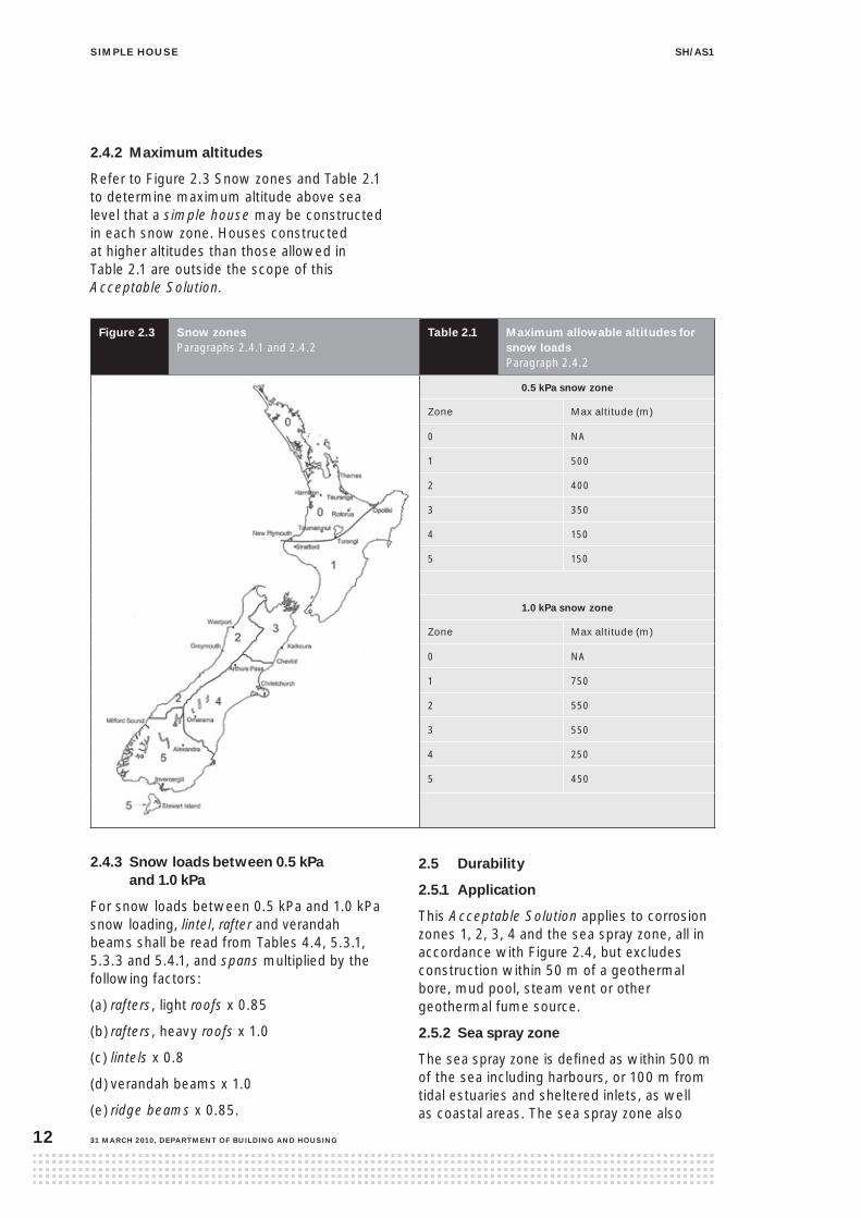
2.4.2 Maximum altitudes
Refer to Figure 2.3 Snow zones and Table 2.1 to determine maximum altitude above sea level that a simple house may be constructed in each snow zone. Houses constructed at higher altitudes than those allowed in Table 2.1 are outside the scope of this Acceptable Solution.
figure 2.3 snow zones Paragraphs 2.4.1 and 2.4.2
table 2.1 Maximum allowable altitudes for snow loadsParagraph 2.4.2
0.5 kpa snow zone
Zone Max altitude (m)
0 NA
1 500
2 400
3 350
4 150
5 150
1.0 kpa snow zone
Zone Max altitude (m)
0 NA
1 750
2 550
3 550
4 250
5 450
2.4.3 snow loads between 0.5 kpa and 1.0 kpa
For snow loads between 0.5 kPa and 1.0 kPa snow loading, lintel, rafter and verandah beams shall be read from Tables 4.4, 5.3.1, 5.3.3 and 5.4.1, and spans multiplied by the following factors:
(a) rafters, light roofs x 0.85
(b) rafters, heavy roofs x 1.0
(c) lintels x 0.8
(d) verandah beams x 1.0
(e) ridge beams x 0.85.
2.5 Durability
2.5.1 application
This Acceptable Solution applies to corrosion zones 1, 2, 3, 4 and the sea spray zone, all in accordance with Figure 2.4, but excludes construction within 50 m of a geothermal bore, mud pool, steam vent or other geothermal fume source.
2.5.2 sea spray zone
The sea spray zone is defined as within 500 m of the sea including harbours, or 100 m from tidal estuaries and sheltered inlets, as well as coastal areas. The sea spray zone also

siMple housesh/as1
DepartMent of BuilDing anD housing, 31 March 2010 13
includes all offshore islands including Waiheke Island, Great Barrier Island, Stewart Island and the Chatham Islands and those areas shown in white in Figure 2.4.
2.5.3 industrial atmospheres
Localised areas subject to corrosive industrial atmospheres are outside the scope of this Acceptable Solution.
figure 2.4 corrosion zones – north islandParagraph 2.5
For sea spray zone, refer to Paragraph 2.5.2.

siMple house sh/as1
31 March 2010, DepartMent of BuilDing anD housing14
figure 2.4 corrosion zones – south islandParagraph 2.5
For sea spray zone, refer to Paragraph 2.5.2.

siMple housesh/as1
DepartMent of BuilDing anD housing, 31 March 2010 15
2.5.4 protection of metal components
Metal components shall be protected as follows:
• steel fixings and fastenings excluding nails and screws, as per Table 2.2
• galvanising of steel components other than nails and screws, as per Table 2.3
• steel items such as nails and screws used for framing and cladding, as per Table 2.4.
table 2.2 protection required for steel fixings and fastenings excluding nails and screws(1)
Paragraph 2.5 and Figure 2.4
Zones/environment Material/protection
Closed (dry, internal location, not subject to airborne salts or rain wetting)
Anywhere in New Zealand Mild steel (uncoated, non-galvanised)
Roof spaces
Nail plates Continuously coated galvanised steel (2)
Wire dogs, bolts Hot-dipped galvanised steel (2)
Sheltered (open to airborne salts, but not rain washed), or Exposed (open to airborne salts and rain wetting)
Sea spray zone, and zone 1 (refer to Figure 2.4) Type 304 stainless steel
Zones 2, 3 and 4 (refer to Figure 2.4) Hot-dipped galvanised steel (2)
(1) Items described in this table are steel fasteners used in joining timber, such as nail plates, bolts, brackets, wire dogs
and similar, but not including nails or screws (refer to Table 2.4) and are required to last for the life of the building,
or not less than 50 years.
(2) All galvanising weights to steel shall be as given in Table 2.3.
table 2.3 galvanising of steel components other than nails and screws Paragraph 2.5
component Durability (years) standard protection required
Bolts in any location that require galvanising (see Table 2.2)
50 AS/NZS 4680 and AS 1214 375 g/m² average (check particular standards for details)
Nail plates and brackets used in ‘sheltered’ or ‘exposed’ locations
50 AS/NZS 4680 Not less than 390 g/m² (and to comply with Tables 1 and 2 of the Standard)
Nail plates used in roof spaces 50 AS 1397 Z275
Wire dogs in any location that requires galvanising (see Table 2.2)
50 260 g/m²
Mild steel angles for masonry veneer
50 AS/NZS 2699.3 600 g/m²
Wall ties 50 AS/NZS 2699.1 430 g/m²
Note 1: 50 year durability means the life of the building, being not less than 50 years.
Note 2: Sheltered refers to locations open to airborne salts, but not rain washed. Exposed refers to locations open
to airborne salts and rain wetting.

siMple house sh/as1
31 March 2010, DepartMent of BuilDing anD housing16
table 2.4 steel items such as nails and screws used for fixing framing and cladding(1) Paragraph 2.5 and Figure 2.4
Simple house location Nail or screw use
Cladding that acts
as bracing (50 year
durability)
Non-structural
cladding (15 year
durability)
Framing in ‘closed’
areas including roof
spaces
Framing in
‘sheltered’ and
‘exposed’ areas
Sea spray or zone 1 (see Figure 2.4)
Excluded Galvanised steel Mild steel Galvanised steel
Other areas Excluded Galvanised steel Mild steel Galvanised steel
(1) Nails and screws fixed into piles within 600 mm of the ground shall be minimum Type 304 stainless steel.
Note 1: 50 year durability means the life of the building, being not less than 50 years.
Note 2: Sheltered refers to locations open to airborne salts, but not rain washed. Exposed refers to locations open
to airborne salts and rain wetting.
2.6 flashing and materials
2.6.1 flashing and material selection
Flashings and flashing fixings shall be selected in accordance with Paragraph 2.6.2 and Tables 2.5 and 2.6.
2.6.2 flashing materials
Flashings shall be selected from the following materials (refer to the Definitions for specific material requirements):
(a) aluminium flashings, minimum 0.7 mm thick
(b) aluminium-zinc coated steel flashings, with BMT of 0.55 mm generally or 0.4 mm for roll-formed ridge flashings
(c) galvanised steel flashings, with BMT of 0.55 mm generally or 0.4 mm for roll-formed ridge flashings
(d) uPVC flashings, minimum of 0.75 mm thick
(e) stainless steel flashings, minimum of 0.45 mm thick
(f) sheet lead flashings, minimum mass of 17 kg/m²
(g) butyl flashings, minimum of 1.0 mm thick.

siMple housesh/as1
DepartMent of BuilDing anD housing, 31 March 2010 17
table 2.5 compatibility of materials in contact Paragraph 2.6
Cla
y b
rick
s (c
emen
t m
ort
ar)
Fib
re c
emen
t, p
ain
ted
Tim
ber
, co
pp
er t
reat
ed, u
np
ain
ted
Tim
ber
, pai
nte
d
Alu
min
ium
, an
od
ised
or
mill
-fin
ish
Alu
min
ium
, co
ated
(1)
Lea
d (
incl
ud
ing
lead
-ed
ged
), u
np
ain
ted
Ro
of
tile
s, m
aso
nry
gla
zed
or
pai
nte
d
Sta
inle
ss s
teel
Ste
el, g
alva
nis
ed c
oil
-co
ated
(1)
Zin
c/al
um
iniu
m c
oat
ed (1
)
Zin
c/al
um
iniu
m, u
np
ain
ted
Aluminium, anodised or mill-finish Sea Spray, Zone 1 n Y n Y Y Y n Y n Y Y Y
Zones 2, 3, 4 n Y n Y Y Y n Y Y Y Y Y
Aluminium, coated (1)
Sea Spray, Zone 1 n Y n Y Y Y n Y n Y Y Y
Zones 2, 3, 4 n Y Y Y Y Y n Y Y Y Y Y
Lead (including lead-edged), unpainted
Sea Spray, Zone 1 Y Y n Y n n Y Y n Y n n
Zones 2, 3, 4 Y Y n Y n n Y Y Y Y n n
Roof tiles, masonry glazed or painted
Sea Spray, Zone 1 Y Y Y Y Y Y Y Y Y Y Y Y
Zones 2, 3, 4 Y Y Y Y Y Y Y Y Y Y Y Y
Stainless steel
Sea Spray, Zone 1 Y Y Y Y n n n Y Y n n n
Zones 2, 3, 4 Y Y Y Y Y Y Y Y Y Y Y Y
Steel, galvanised coil-coated (1) Sea Spray, Zone 1 Y Y n Y Y Y n Y n Y Y Y
Zones 2, 3, 4 Y Y Y Y Y Y Y Y Y Y Y Y
Zinc/aluminium steel, coated (1) Sea Spray, Zone 1 Y Y n Y Y Y n Y n Y Y Y
Zones 2, 3, 4 Y Y Y Y Y Y Y Y Y Y Y Y
Zinc/aluminium steel, unpainted Sea Spray, Zone 1 n Y n Y Y Y n Y n Y Y Y
Zones 2, 3, 4 n Y n Y Y Y n Y Y Y Y Y
Compatibility of fixings with flashings Flashing materials
Aluminium fixings
Sea Spray, Zone 1 Y Y n Y n Y Y Y
Zones 2, 3, 4 Y Y n Y Y Y Y Y
Galvanised steel fixings
Sea Spray, Zone 1 Y Y n Y n Y Y Y
Zones 2, 3, 4 Y Y Y Y n Y Y Y
Stainless steel fixings
Sea Spray, Zone 1 n n n Y Y n n n
Zones 2, 3, 4 Y Y Y Y Y Y Y Y
Y = Acceptable, n = Unacceptable
Note 1: ‘Coated’ includes factory-painted, coil-coated and powder-coated
Note 2: Refer to Paragraph 2.5 Durability for descriptions of corrosion zones and fixings

siMple house sh/as1
31 March 2010, DepartMent of BuilDing anD housing18
table 2.6 compatibility of materials subject to water runoff Paragraph 2.6
Cla
y b
rick
s (c
emen
t m
ort
ar)
Fib
re c
emen
t, p
ain
ted
Tim
ber
, co
pp
er t
reat
ed, u
np
ain
ted
Tim
ber
, pai
nte
d
Alu
min
ium
, an
od
ised
or
mill
-fin
ish
Alu
min
ium
, co
ated
(1)
Lea
d (
incl
ud
ing
lead
-ed
ged
), u
np
ain
ted
Ro
of
tile
s, m
aso
nry
gla
zed
or
pai
nte
d
Sta
inle
ss s
teel
Ste
el, g
alva
nis
ed c
oil
-co
ated
(1)
Zin
c/al
um
iniu
m c
oat
ed (1
)
Zin
c/al
um
iniu
m, u
np
ain
ted
Clay bricks (cement mortar) Y Y Y Y n n Y Y Y Y Y n
Fibre cement, painted Y Y Y Y Y Y Y Y Y Y Y Y
Timber, copper treated, unpainted Y Y Y Y n n n Y Y n n n
Timber, painted Y Y Y Y Y Y Y Y Y Y Y Y
Aluminium, anodised or mill-finish Y Y Y Y Y Y Y Y Y Y Y Y
Aluminium, coated (1) Y Y Y Y Y Y Y Y Y Y Y Y
Lead (including lead-edged), unpainted Y Y Y Y n n Y Y Y Y Y n
Roof tiles, masonry glazed or painted Y Y Y Y Y Y Y Y Y Y Y Y
Stainless steel Y Y Y Y Y Y Y Y Y Y Y Y
Steel, galvanised coil-coated (1) Y Y Y Y Y Y Y Y Y Y Y Y
Zinc/aluminium coated (1) Y Y Y Y Y Y Y Y Y Y Y Y
Zinc/aluminium, unpainted Y Y Y Y Y Y Y Y Y Y Y Y
Y = Acceptable, n = Unacceptable
Note 1: ‘Coated’ includes factory-painted, coil-coated and powder-coated.
Note 2: Refer to Paragraph 2.5 Durability for descriptions of corrosion zones and fixings.
Material that water flows froM
Material that water flows onto

siMple housesh/as1
DepartMent of BuilDing anD housing, 31 March 2010 19
2.7 timber
2.7.1 grade, species and treatment
The timber grade, species and preservative treatment for timber and timber products in this Acceptable Solution shall be in accordance
with Table 2.7. Where not otherwise specified, they shall comply with NZS 3602. All timber preservative treatments shall be in accordance with NZS 3640. Timber grading shall comply with NZS 3622.
table 2.7 timber – grade, species, preservative treatment Paragraph 2.7.1
Timber member Paragraph Grade Species Treatment – minimum
Timber pile 3.3.1.2, 3.4.4 to NZS 3605 and branded
Radiata pine H5
Anchor pile 3.3.5 to NZS 3605 branded “A”
Radiata pine H5
Timber subfloor framing – protected from weather
3.3.1.2 VSG 8 or MSG 8 Radiata pine or Douglas fir
H1.2
Timber subfloor framing – exposed to weather 3.3.1.2 VSG 8 or MSG 8 Radiata pine H3.2
Flooring – particleboard 3.3.15.1 to AS/NZS 1859, CD grade none
Flooring – plywood 3.3.15.1 to AS/NZS 2269, CD grade H3 treated to AS/NZS 1604
Wet area flooring – plywood 3.3.15.1 to AS/NZS 2269, CD grade H3 treated to AS/NZS 1604
Perimeter baseboard 3.3.16 Dressing Radiata pine H3.2
Timber deck and barrier 3.4.2 VSG 8 or MSG 8 Radiata pine H3.2
Timber decking 3.4.2 Merchantable Radiata pine
H3.2
Wall framing Section 4 VSG 8 or MSG 8 Radiata pine or Douglas fir
H1.2
Wall bracing – plywood 4.6.3.3 to AS/NZS 2269, DD grade H3 treated to AS/NZS 1604
Purlin 5.1.4.1 VSG 8 or MSG 8 Radiata pine or Douglas fir
H1.2
Tile batten 5.1.4.1 No 1 Framing and free from knots
Radiata pine or Douglas fir
H1.2
Roof framing Section 5 VSG 8 or MSG 8 Radiata pine or Douglas Fir
H1.2
Roof truss 5.2 VSG 8 or MSG 8 Radiata pine or Douglas Fir
H1.2
Skillion roof framing 5.3 VSG 8 or MSG 8 Radiata pine or Douglas Fir
H1.2
Verandah framing 5.4 VSG 8 or MSG 8 Radiata pine or Douglas Fir
H1.2
Verandah post, not in ground contact 5.4.2 VSG 8 or MSG 8 Radiata pine H3.2
Timber joinery reveal 6.1.3.4 Select Radiata pine H1.2
Weatherboard, paint protected 6.2.1.2, 6.3.1.2
Dressing or finger-jointed
Radiata pine H3.1
Exterior finishing timber, cover or corner board, cover battens, etc, paint protected
6.2.6, 6.3.7, 6.5.2.2
Dressing or finger-jointed
Radiata pine H3.1
Plywood wall cladding 6.5.2 to AS/NZS 2269 CD grade H3 treated to AS/NZS 1604
Timber door jamb 6.7.5 Select A Radiata pine H3.2
Valley board 7.1.7, 7.2.4.10, 7.3.4, 7.4.5
Merchantable Radiata pine H1.2
Anti-ponding board 7.4.4 to AS/NZS 2269, DD grade H3 treated to AS/NZS 1604

siMple house sh/as1
31 March 2010, DepartMent of BuilDing anD housing20
2.7.2 timber sizes
The cross-section dimensions of timber given in this Acceptable Solution are the actual finished sizes that shall be used.
2.7.3 laminated members
Timber members 90 mm thick may be laminated from two 45 mm thick members of the corresponding depth or width specified. Members shall be nailed with 75 x 3.15 mm hand-driven or 90 x 3.15 mm power-driven nails at 250 mm centres along the full length, and nailed from alternate sides. Members more than 140 mm deep or wide shall have two rows of nails.
2.7.4 timber connectors or fixings
Where the capacity of fixings are specifically identified in this Acceptable Solution, proprietary fasteners may be substituted (refer to Definitions for manufacturing requirements for proprietary fasteners).
2.7.5 Bolts
In bolted joints, washers shall be at each surface under the bolt head and the nut. For an M12 bolt the washers shall be not less than 50 x 50 x 3 mm if square or not less than 55 mm diameter x 3 mm if round. Bolts shall comply with the requirements of AS 1111.
2.8 energy efficiency
2.8.1 insulation
Insulating products with a minimum thermal resistance given in Table 2.8 shall be provided to roofs, walls, floors and glazing.
table 2.8 r-value of installed insulation productParagraphs 2.8.1 and 2.8.2
Element Position of
insulation
Minimum
thermal
resistance
Trussed roof over ceiling battens, between bottom chord
R 3.6
Skillion roof between rafters R 3.2
External walls framing cavity R 2.2
Glazing all glazing, except: houses in Kaipara, Whangarei and Far North District Councils may be single-glazed with a minimum R-value
R 0.26
R 0.15
Floor – option 1
bulk insulation between floor joists
R1.4
Floor – option 2
concrete slab-on- ground
Not required
Comment:NZS 4246: Energy Efficiency – Installing Insulation in Residential Buildings is a New Zealand Standard that provides guidance on the installation of insulation.
Additional insulation for comfort and energy efficiency can be achieved by providing:
(a) insulation to edge of floor slab, or
(b) underfloor insulation to slab (refer to Paragraph 3.1.1.2), or
(c) additional underfloor insulation to suspended timber floor, or
(d) high performance insulation to walls and additional insulation to ceilings.
Where additional levels of thermal insulation are desired, refer to the BRANZ House Insulation Guide.

siMple housesh/as1
DepartMent of BuilDing anD housing, 31 March 2010 21
2.8.2 thermal envelope
An attached garage is not required to be part of the thermal envelope of the simple house, provided that any internal common walls separating the house and garage shall have the same thermal resistance as the external walls of the house. Refer to Table 2.8 and Figure 2.5.
figure 2.5 thermal envelope Paragraph 2.8.2
2.8.3 glazing
The total glazed area shall not be more than 30% of the total wall area.
A minimum of 30% of the total glazed area shall be orientated to the North. For the purposes of this paragraph, ‘North’ is determined as between 315 and 45 degrees of true north.

siMple house sh/as1
31 March 2010, DepartMent of BuilDing anD housing22
3.1.1 thickness
3.1.1.1 Slab thickness
The minimum thickness of the floor slab shall be 100 mm – see Figure 3.1.1.
figure 3.1.1 construction of slab-on-ground Paragraphs 3.1.1.1, 3.1.4 and 3.1.7.1
3.1.1.2 Underfloor thermal insulation
Thermal insulating material may be used under a concrete slab-on-ground provided there is no reduction in slab thickness. Where underfloor insulation (refer to Paragraphs 2.8 and 10.0) is used, it shall be laid over damp-proof membrane (DPM). Underfloor insulation is not permitted under foundations to loadbearing walls.
3.1.2 shrinkage control joints
3.1.2.1 General
Concrete slab shrinkage control joints shall be formed by saw cutting the slab after initial hardening. The saw cuts shall extend only to a quarter of the depth of the slab. Reinforcement is not to be damaged by saw cutting. Saw cutting shall take place no later than 24 hours after concrete placement for average ambient temperatures above 20° C, and 48 hours after concrete placement for average ambient temperatures below 20° C.
contents
3.1.1 Thickness
3.1.2 Shrinkage control joints
3.1.3 Ground clearances
3.1.4 Granular fill
3.1.5 Damp-proof membrane (DPM)
3.1.6 Concrete strength
3.1.7 Slab reinforcing
3.1.8 Concrete slab edge details
3.1.9 Support of internal loadbearing walls
3.1.10 Construction moisture in concrete
figures
3.1.1 Construction of slab-on-ground
3.1.2 Concrete slab shrinkage control joints
3.1.3 Supplementary steel
3.1.4 Height of slab above ground
3.1.5 Foundation edge details – lightweight cladding
3.1.6 Foundation edge details – masonry veneer cladding
3.1.7 Alternative concrete masonry
3.0 foundations
3.1 slab-on-ground

siMple housesh/as1
DepartMent of BuilDing anD housing, 31 March 2010 23
3.1.2.2 Placement
Concrete slab shrinkage control joints shall:
(a) be positioned to coincide with major changes in plan (see Figure 3.1.2)
(b) have supplementary steel placed in accordance with Figure 3.1.3, but not across concrete slab shrinkage control joints
(c) have supplementary concrete slab shrinkage control joints placed to ensure distances between control joints do not exceed 6 m
(d) have supplementary concrete slab shrinkage control joints placed to ensure slab bays are limited to a maximum ratio of length:width of 2:1.
figure 3.1.2 concrete slab shrinkage control joint Paragraph 3.1.2.2

siMple house sh/as1
31 March 2010, DepartMent of BuilDing anD housing24
figure 3.1.3 supplementary steel Paragraph 3.1.2.2
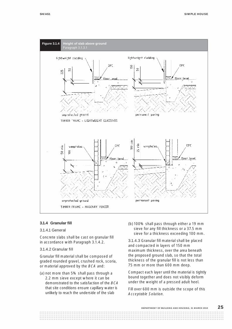
3.1.3 ground clearances
3.1.3.1 Finished floor level
The height of the top surface of the floor slab above adjacent ground (refer to Figures 3.1.4 and 6.1.6) shall be no less than:
(a) for cladding other than masonry veneer:
(i) 150 mm if ground is permanently paved, or
(ii) 225 mm if ground is unpaved
(b) for masonry veneer wall claddings:
(i) 100 mm if ground is permanently paved, or
(ii) 150 mm if ground is unpaved.
3.1.3.2 The finished ground level adjoining the concrete slab-on-ground shall be formed at a slope of not less than 1 in 25 (1:25), for a distance of at least 1 m, falling away from the simple house.
3.1.3.3 At garage openings maintain clearance to claddings in accordance with Figure 6.1.6.
siMple housesh/as1
DepartMent of BuilDing anD housing, 31 March 2010 25
figure 3.1.4 height of slab above ground Paragraph 3.1.3.1
3.1.4 granular fill
3.1.4.1 General
Concrete slabs shall be cast on granular fill in accordance with Paragraph 3.1.4.2.
3.1.4.2 Granular fill
Granular fill material shall be composed of graded rounded gravel, crushed rock, scoria, or material approved by the BCA and:
(a) not more than 5% shall pass through a 2.2 mm sieve except where it can be demonstrated to the satisfaction of the BCA that site conditions ensure capillary water is unlikely to reach the underside of the slab
(b) 100% shall pass through either a 19 mm sieve for any fill thickness or a 37.5 mm sieve for a thickness exceeding 100 mm.
3.1.4.3 Granular fill material shall be placed and compacted in layers of 150 mm maximum thickness, over the area beneath the proposed ground slab, so that the total thickness of the granular fill is not less than 75 mm or more than 600 mm deep.
Compact each layer until the material is tightly bound together and does not visibly deform under the weight of a pressed adult heel.
Fill over 600 mm is outside the scope of this Acceptable Solution.
siMple house sh/as1
31 March 2010, DepartMent of BuilDing anD housing26
3.1.5 Damp-proof membrane (DpM)
3.1.5.1 The concrete floor slab cast on the ground shall have a damp-proof membrane (DPM) laid between the ground and the slab. The DPM shall be laid over the total area of the slab and be turned down into the excavation to finish at the outside edge of the footing – see Figures 3.1.5 and 3.1.6.
3.1.5.2 The DPM material shall consist of a single unprotected layer of polyethylene not less than 0.25 mm thick, and:
(a) have lap joints not less than 150 mm wide, sealed with pressure-sensitive plastic tape not less than 50 mm wide
(b) be protected from damage
(c) have penetrations by services, reinforcing or other objects sealed by taping.
3.1.5.3 Where the granular surface is likely to puncture the DPM, it shall be protected by sand blinding of a nominal maximum thickness of 25 mm.
3.1.6 concrete strength
3.1.6.1 Concrete shall be ordinary grade as specified in NZS 3109.
3.1.6.2 Minimum specified concrete strength at 28 days shall be:
(a) 10 MPa for unreinforced concrete used in mass foundations
(b) 17.5 MPa for unreinforced concrete used in piled foundations
(c) 20 MPa for reinforced concrete slabs and foundations in zones 1, 2, 3 and 4.
(d) 25 MPa for reinforced concrete slabs and foundations in the sea spray zone.
Refer to Paragraph 2.5 for a description of the different corrosion zones.
3.1.7 slab reinforcing
All slabs shall be reinforced. Reinforcing bars and hard drawn mild steel wire mesh shall conform to AS/NZS 4671.
3.1.7.1 Cover
Minimum concrete cover to steel reinforcement shall be:
(a) 75 mm when concrete is placed directly on or against the ground
(b) 50 mm when concrete is placed on DPM and in all other situations where concrete is placed in formwork
(c) 30 mm from the top of a wall or floor slab which is in an internal area (refer to Figure 3.1.1)
(d) 50 mm from the top of any exposed wall or floor slab.
3.1.7.2 Ground slab reinforcing shall extend to within 75 mm of the outside edge of the slab (including the foundation) and be supported in final position prior to pouring concrete. Reinforcing shall consist of a minimum of 2.27 kg/m2 welded steel mesh complying with AS/NZS 4671. Minimum lap of reinforcing mesh shall be 225 mm at sheet joints.
3.1.8 concrete slab edge details
3.1.8.1 The combined foundation edge details shall be constructed in accordance with Figures 3.1.5 and 3.1.6 or Figure 3.1.7

siMple housesh/as1
DepartMent of BuilDing anD housing, 31 March 2010 27
figure 3.1.5 foundation edge details – lightweight cladding Paragraphs 3.1.5 and 3.1.8.1
figure 3.1.6 foundation edge details – masonry veneer cladding Paragraphs 3.1.5 and 3.1.8.1

siMple house sh/as1
31 March 2010, DepartMent of BuilDing anD housing28
figure 3.1.7 alternative concrete masonry footingParagraph 3.1.8.1
3.1.9 support of internal loadbearing walls
3.1.9.1 All internal walls may be supported on the reinforced floor slab without slab thickening, except for those slabs requiring thickenings in expansive soils (refer to Paragraph 3.2).
3.1.10 construction moisture in concrete
Concrete floors shall be sufficiently dry to give a relative humidity reading of less than 75% at the time of laying fixed floor coverings when measured in accordance with BRANZ Bulletin 330 ‘Thin Flooring Materials – 2 – Preparation and Laying’.

siMple housesh/as1
DepartMent of BuilDing anD housing, 31 March 2010 29
3.2.1 identification of expansive soils
3.2.1.1 Should reasonable enquiry as outlined in Paragraph 2.1.3.1 show any signs of expansive soils, the expansive soil class, as defined in AS 2870, shall be established. This shall be established by one or all of:
(a) enquiry to the local territorial authority
(b) reference to the certificate of suitability issued in terms of NZS 4431
(c) a soil test undertaken by a suitably qualified soils engineer.
3.2.1.2 Expansive soil class shall be defined as:
(a) Slightly ‘S’, having an Iss Range of 0–1.9%, and a 500 year design characteristic surface movement return (ys) of 22 mm, or
(b) Moderately ‘M’, having an Iss Range of 2.0–3.7% and a 500 year design characteristic surface movement return (ys) of 44 mm, or
(c) Highly ‘H’, having an Iss Range of 3.8–6.5% and a 500 year design characteristic surface movement return (ys) of 78 mm, or
(d) Extremely ‘E’, having an Iss Range of 6.6– 7.5% and a 500 year design characteristic surface movement return (ys) of 90 mm.
3.2.2 Maximum aspect ratio of concrete slabs
The aspect ratio of the concrete slabs or bays of concrete slabs, such as in the case of L, T or boomerang concrete slab shapes, shall not exceed 5 to 1 (length to width).
3.2.3 foundation details
3.2.3.1 For the identified expansive soil class the foundation details, external and internal thickenings shall be as follows.
(a) For lightweight claddings refer to Table 3.2.1 and Figure 3.2.1.
(b) For masonry veneer claddings refer to Table 3.2.2 and Figure 3.2.2.
contents
3.2.1 Identification of expansive soils
3.2.2 Maximum aspect ratio of concrete slabs
3.2.3 Foundation details
figures
3.2.1 Reinforced concrete foundations in expansive soils for lightweight claddings
3.2.2 Reinforced concrete foundations in expansive soils for masonry veneer
tables
3.2.1 Reinforced concrete foundations in expansive soils for lightweight claddings
3.2.2 Reinforced concrete foundations in expansive soils for masonry veneer
3.2 slab-on-ground in expansive soils
siMple house sh/as1
31 March 2010, DepartMent of BuilDing anD housing30
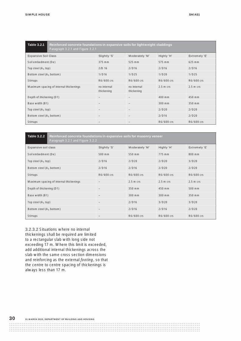
table 3.2.1 reinforced concrete foundations in expansive soils for lightweight claddings Paragraph 3.2.1 and Figure 3.2.1
Expansive Soil Class Slightly ‘S’ Moderately ‘M’ Highly ‘H’ Extremely ‘E’
Soil embedment (De) 375 mm 525 mm 575 mm 625 mm
Top steel (As top) 2/D 16 2/ D16 2/ D16 2/ D16
Bottom steel (As bottom) 1/ D16 1/ D25 1/ D20 1/ D25
Stirrups R6/ 600 crs R6/ 600 crs R6/ 600 crs R6/ 600 crs
Maximum spacing of internal thickenings no internal thickening
no internal thickening
2.5 m crs 2.5 m crs
Depth of thickening (D1) – – 400 mm 450 mm
Base width (B1) – – 300 mm 350 mm
Top steel (As top) – – 2/ D20 2/ D20
Bottom steel (As bottom) – – 2/ D16 2/ D20
Stirrups – – R6/ 600 crs R6/ 600 crs
table 3.2.2 reinforced concrete foundations in expansive soils for masonry veneer Paragraph 3.2.1 and Figure 3.2.2
Expansive soil class Slightly ‘S’ Moderately ‘M’ Highly ‘H’ Extremely ‘E’
Soil embedment (De) 500 mm 550 mm 775 mm 800 mm
Top steel (As top) 2/ D16 2/ D20 2/ D20 3/ D20
Bottom steel (As bottom) 2/ D16 2/ D16 2/ D20 2/ D20
Stirrups R6/ 600 crs R6/ 600 crs R6/ 600 crs R6/ 600 crs
Maximum spacing of internal thickenings – 2.5 m crs 2.5 m crs 2.5 m crs
Depth of thickening (D1) – 350 mm 450 mm 500 mm
Base width (B1) – 300 mm 300 mm 350 mm
Top steel (As top) – 2/ D16 3/ D20 3/ D20
Bottom steel (As bottom) – 2/ D16 2/ D16 2/ D20
Stirrups – R6/ 600 crs R6/ 600 crs R6/ 600 crs
3.2.3.2 Situations where no internal thickenings shall be required are limited to a rectangular slab with long side not exceeding 17 m. Where this limit is exceeded, add additional internal thickenings across the slab with the same cross section dimensions and reinforcing as the external footing, so that the centre to centre spacing of thickenings is always less than 17 m.

siMple housesh/as1
DepartMent of BuilDing anD housing, 31 March 2010 31
figure 3.2.1 reinforced concrete foundations in expansive soils for lightweight claddings Paragraph 3.2.1 and Table 3.2.1
figure 3.2.2 reinforced concrete foundations in expansive soils for masonry veneer Paragraph 3.2.1 and Table 3.2.2

siMple house sh/as1
31 March 2010, DepartMent of BuilDing anD housing32
Comment Maintenance of foundations in expansive soilsNormal maintenance is that work generally recognised as necessary to achieve the expected performance over time of the foundation located on expansive soils. Unless otherwise specified by the designer and noted on the drawings, basic normal maintenance tasks shall ensure that:
(a) the drainage and wetting of the site is controlled so that extremes of wetting and drying of the soils is prevented
(b) the position and operation of gardens adjacent to the dwelling are controlled, and the planting of trees near to foundations is suitably restricted
(c) any leaks which develop in plumbing, stormwater or sanitary sewage systems are repaired promptly.

siMple housesh/as1
DepartMent of BuilDing anD housing, 31 March 2010 33
contents
3.3.1 General
3.3.2 Piles
3.3.3 Footings
3.3.4 Ordinary piles
3.3.5 Anchor piles
3.3.6 Braced pile systems
3.3.7 Diagonal braces
3.3.8 Brace connections
3.3.9 Fixings of bearers and joists
3.3.10 Subfloor bracing
3.3.11 Support of loadbearing and wall bracing elements
3.3.12 Subfloor bracing demand
3.3.13 Bearers
3.3.14 Floor joists
3.3.15 Sheet flooring
3.3.16 Subfloor ventilation
3.3.17 Access
figures
3.3.1 Ordinary pile directly connected to bearer
3.3.2 Anchor pile directly connected to joist and bearer
3.3.3 Anchor pile directly connected to bearer only
3.3.4 Braced pile system – brace connected to pile
3.3.5 Braced pile system – brace connected to bearer
3.3.6 Braced pile system – brace connected to joist
3.3.7 Support of loadbearing walls
3.3.8 Joints in bearers
3.3.9 Joints in floor joists
3.3.10 Floor joist layout criteria
tables
3.3.1 Subfloor bracing demand for wind
3.3.2 Subfloor bracing demand for earthquake
3.3.3 Maximum spans of floor joists
3.3.4 Cantilevered floor joists
3.3 piled foundations

siMple house sh/as1
31 March 2010, DepartMent of BuilDing anD housing34
3.3.1 general
3.3.1.1 Piled foundations to support a timber floor shall consist of a system of:
(a) ordinary piles, as described in Paragraph 3.3.4
(b) anchor piles, as described in Paragraph 3.3.5
(c) braced piles as described in Paragraph 3.3.6.
3.3.1.2 Materials
The grade, species and preservative treatment for timber piles in piled foundations shall be in accordance with Table 2.7.
The grade, species and preservative treatment for timber subframing (for example braces, bearers, floor joists, blocking ) shall be in accordance with Table 2.7. This table identifies the separate requirements for timber that is protected from the weather but exposed to ground atmosphere, or timber that is exposed to exterior weather conditions but not in ground contact.
Concrete for pile footings shall be ordinary grade complying with NZS 3109. For strength see Paragraph 3.1.6.2.
Any steel connections within 600 mm of the cleared ground level shall be a minimum of Type 304 stainless steel.
3.3.2 piles
3.3.2.1 Piles shall directly support the bearers.
3.3.2.2 Pile height
The maximum height of piles above cleared ground level (CGL) shall be:
(a) 600 mm to the centre of the highest fixing for anchor piles, and
(b) dimensioned so that height to finished floor level (FFL) does not exceed 2.0 m.
The minimum clear distance under a bearer, supported by a pile, to cleared ground level is 300 mm.
3.3.2.3 Cross section
Timber piles shall be a minimum of 140 mm diameter for round piles or 125 x 125 mm square for sawn piles.
3.3.3 footings
3.3.3.1 Loading
Piles shall not be loaded with the dead weight of the simple house until the concrete is a minimum of 24 hours old. The concrete shall not have a slump exceeding 60 mm at the time of placing. If at any time during the 24 hours the ambient temperature drops below 10° C, then the time before loading shall be extended to 48 hours.
3.3.3.2 Minimum depth
The bottom of a pile footing shall be concrete cast in-situ against good ground at a minimum depth below cleared ground level of:
(a) for an ordinary pile – 200 mm
(b) for a braced pile – 450 mm
(c) for an anchor pile – 900 mm.
The minimum thickness of concrete shall be 200 mm.
3.3.3.3 Plan size
All footings shall be 350 x 350 mm if square or 400 mm diameter if circular.
3.3.3.4 Embedment
Each pile shall be embedded in its footing such that there is a minimum depth of 100 mm concrete below the bottom of the pile.

siMple housesh/as1
DepartMent of BuilDing anD housing, 31 March 2010 35
3.3.4 ordinary piles
The fixings of bearers to ordinary piles shall be 2/4.9 mm wire dogs together with 2/100 x 3.75 mm nails or 4/100 x 3.75 mm nails skew driven into the piles (see Figure 3.3.1).
figure 3.3.1 ordinary pile directly connected to bearer Paragraph 3.3.4
3.3.5 anchor piles
The fixings of bearers and floor joists to anchor piles shall be M12 bolts or 12 mm threaded rod as shown in Figures 3.3.2 and 3.3.3. Alternative proprietary fixings having a capacity of 12 kN in tension and compression along the bearer and timber joist may be used.

siMple house sh/as1
31 March 2010, DepartMent of BuilDing anD housing36
figure 3.3.2 anchor pile directly connected to joist and bearer Paragraph 3.3.5

siMple housesh/as1
DepartMent of BuilDing anD housing, 31 March 2010 37
figure 3.3.3 anchor pile directly connected to bearer only Paragraph 3.3.5
3.3.6 Braced pile systems
3.3.6.1 A braced pile system consists of 2 piles, each with a 450 mm deep footing, between which a diagonal brace is fixed in accordance with Paragraph 3.3.8 (see Figures 3.3.4 to 3.3.6).

siMple house sh/as1
31 March 2010, DepartMent of BuilDing anD housing38
figure 3.3.4 Braced pile system – brace connected to pile Paragraphs 3.3.6 and 3.3.8.3
3.3.6.2 Where a braced pile system is repeated as a series of braced piles, with braces sloping in the same direction, it shall be in accordance with Figure 3.3.4.
3.3.6.3 Only one brace shall be attached to the top of a braced pile. Two braces may be attached to the bottom of a braced pile, but only if they are at right angles to each other and not in line.
3.3.6.4 Height
The minimum height of a braced pile above cleared ground level shall be three times the distance from cleared ground level to the lower brace fixing (see Figures 3.3.4 to 3.3.6).

siMple housesh/as1
DepartMent of BuilDing anD housing, 31 March 2010 39
figure 3.3.5 Braced pile system – brace connected to bearer Paragraphs 3.3.6 and 3.3.8.3
siMple house sh/as1
31 March 2010, DepartMent of BuilDing anD housing40
3.3.7 Diagonal braces
3.3.7.1 Diagonal braces shall slope between 10° and 45° to the horizontal except that a minimum slope of 6° may be used when the braces are connected to a bearer or joist.
3.3.7.2 A diagonal brace shall consist of one continuous length of 90 x 70 mm timber.
3.3.8 Brace connections
3.3.8.1 A diagonal brace shall be connected at each end by an M12 bolt with a 50 x 50 x 3 mm washer at each end passing through the centre line of the brace not less than 90 mm from its end and at right angles to the brace.
3.3.8.2 Brace, lower end connection
The lower end of the diagonal brace shall be fixed to the bottom of a braced pile by a M12 bolt through the centre line of the pile, between 200 and 300 mm above cleared ground level.
3.3.8.3 Brace, upper end connection
The upper end of the diagonal timber brace shall be fixed to one of the following members as set out below.
(a) Braced pile: the bolt shall pass through the top end of the pile not less than 90 mm, nor more than 150 mm, from the top of the pile. The bolt shall pass through the centre line of the pile (see Figure 3.3.4).
(b) Bearer: the bolt shall pass through the centre line of the bearer not more than 200 mm measured along the bearer from the centre line of the nearest support (see Figure 3.3.5). Where required for the alignment of the brace, the gap between the bearer and diagonal brace shall be bridged by a timber packer fixed to the bearer with 10/100 x 3.75 mm nails and a fixing having a capacity of 12 kN along the direction of the bearer. The packer shall be the same depth as the bearer and not less than 600 mm long.
(c) Joist: the bolt shall pass through the joist, not less than 50 mm from its lower edge and not more than 200 mm measured along the joist, from the centre line of the nearest pile (see Figure 3.3.6). The top of the diagonal timber brace shall not be more than 150 mm horizontally out of line from the bottom of the brace (see Figure 3.3.6).

siMple housesh/as1
DepartMent of BuilDing anD housing, 31 March 2010 41
3.3.9 fixings of bearers and joists
3.3.9.1 The bearer shall be fixed to each braced pile with either:
(a) a M12 bolt, or
(b) a proprietary fastener of:
(i) 12 kN capacity in the horizontal direction where the brace is attached to the pile
(ii) 12 kN capacity in the vertical direction where the brace is attached to the bearer
(iii) 12 kN capacity in the vertical direction where the brace is attached to the joist.
figure 3.3.6 Braced pile system – brace connected to joist Paragraphs 3.3.6 and 3.3.8.3

siMple house sh/as1
31 March 2010, DepartMent of BuilDing anD housing42
3.3.9.2 Where the brace is attached to the pile, two floor joists in the area immediately above the upper end of the brace shall be fixed to the bearer with fixings each having a capacity in the horizontal direction of the brace of 6 kN.
3.3.9.3 Where the brace is attached to the joist, the joist to bearer fixing shall have a capacity in the vertical direction of 12 kN.
3.3.10 subfloor bracing
3.3.10.1 Bracing lines
Bracing lines providing horizontal support shall run in two directions at right angles to each other and be located:
(a) in perimeter subfloor framing
(b) in internal lines parallel to perimeter subfloor framing
(c) at not more than 6 m spacing
(d) in the perimeter of timber deck structures projecting over 2 m from the simple house.
3.3.10.2 Internal bracing lines
Each internal bracing line shall have a bracing capacity not less than 70 bracing units. Bracing shall be evenly distributed along each line.
3.3.10.3 External bracing lines
Each external subfloor bracing line shall have a total bracing capacity of not less than 10 bracing units per metre of external wall.
3.3.11 support of loadbearing and wall bracing elements
3.3.11.1 A bearer shall be provided within 200 mm, centre-to-centre, of loadbearing walls immediately above, and which are at right angles to the joists (see Figure 3.3.7B).
3.3.11.2 Where a bearer supports a loadbearing wall or wall bracing elements running parallel to the floor joists, it shall itself be supported by a pile within 200 mm, centre-to-centre, of the loadbearing or bracing wall (see Figure 3.3.7C).
figure 3.3.7 support of loadbearing walls Paragraphs 3.3.11.1, 3.3.11.2, 3.3.14.5 and 3.3.14.6

siMple housesh/as1
DepartMent of BuilDing anD housing, 31 March 2010 43
3.3.12 subfloor bracing demand
3.3.12.1 Wind
The total subfloor bracing demand for wind shall be calculated by multiplying the building or roof length ‘L’ perpendicular to the wind direction by the bracing demands as determined by Table 3.3.1 and Figure 4.12. Timber decks can be ignored for wind demand.
table 3.3.1 subfloor bracing demand for windParagraph 3.3.12.1
Height to
apex (H)
Across ridge Along ridge
Bracing demand (BUs/m) of building or roof length ‘L’ perpendicular to wind direction
4 93 111
5 130 147
6 154 166
7 191 203
3.3.12.2 Earthquake
The total subfloor bracing demand for earthquake shall be calculated by multiplying the gross floor area by the bracing demand as per Table 3.3.2.
table 3.3.2 subfloor bracing demand for earthquake Paragraph 3.3.12.2 and 3.3.12.4
Wall cladding Roof cladding Roof pitch
(degrees)
Bracing demand
(BUs/m2)
Weatherboard, sheet cladding – on piles Profiled metal 10-25 9.4
Weatherboard, sheet cladding – on piles Profiled metal 25-35 9.8
Weatherboard, sheet cladding – on piles Masonry tile 10-25 12.1
Weatherboard, sheet cladding – on piles Masonry tile 25-35 13.3
Timber decks Not applicable Not applicable 4.7
Note: Decks with stringers bolted to the simple house on one or more sides and which project no more than 2 m from
the simple house do not require subfloor bracing.

siMple house sh/as1
31 March 2010, DepartMent of BuilDing anD housing44
3.3.12.3 Bracing capacity ratings of subfloor bracing elements
The bracing ratings of subfloor bracing elements are:
(a) braced pile system (consisting of two piles and a diagonal brace) – 120 BUs for earthquake and 160 BUs for wind
(b) anchor piles, rating per pile – 120 BUs for earthquake and 160 BUs for wind.
3.3.12.4 Bracing of timber decks
Decks with stringers bolted to the simple house on one or more sides and which project no more than 2 m from the simple house do not require subfloor bracing. Decks which project more than 2 m from the simple house shall have subfloor bracing provided by anchor and/or braced piles. See Table 3.3.2 for bracing demand.
3.3.12.5 Minimum number of subfloor braces
In no case shall any simple house that has subfloor bracing consisting only of braced pile systems or anchor piles have less than 4 braced pile systems or anchor piles, in each direction placed symmetrically around the simple house perimeter.
3.3.13 Bearers
3.3.13.1 Bearers of solid or nailed laminated timber (see Paragraph 2.7.3) shall be continuous over two or more spans and be laid in straight lines on edge.
3.3.13.2 Sizes
Bearers shall be a minimum of 2/140 x 45 mm or 140 x 90 mm and span a maximum of 1.65 m.
3.3.13.3 Cantilevered bearers
Bearers may project as cantilevers beyond the face of the support to a distance not exceeding 200 mm.
3.3.13.4 Landing
Bearers shall have a minimum landing on their supports of:
(a) where bearers are butted over the support: 45 mm
(b) in all other cases: 90 mm.
Any packing necessary beneath bearers shall be of a material as durable and as incompressible as the bearer itself.
3.3.13.5 Joints
Joints in bearers shall be made only over supports with a connection having a capacity of:
(a) not less than 12 kN in tension or compression along the line of the bearer, or 6 kN each on both sides, if the bearer is one piece of timber, or
(b) 6 kN on one side of the joint when one laminate is continued over the support.
See Figure 3.3.8. Joints shall not occur where the bearer is fixed directly to an anchor pile or braced pile.
figure 3.3.8 Joints in bearers Paragraph 3.3.13.5

siMple housesh/as1
DepartMent of BuilDing anD housing, 31 March 2010 45
3.3.14 floor joists
3.3.14.1 Floor joists shall be 140 x 45 mm with maximum spans in accordance with Table 3.3.3. Fix floor joist to bearers with 2 skewed 100 x 3.75 mm nails or 3 skewed 90 x 3.15 mm power driven nails.
table 3.3.3 Maximum spans of floor joist Paragraph 3.3.14.1
Maximum span of joist (m) Joist centres (mm)
2.70 400
2.60 450
2.00 600
3.3.14.2 Floor joists shall have minimum bearing on their supports of 32 mm.
3.3.14.3 Floor joists may be butted and flitched over a support with a piece of timber of the same dimensions as the joists and extending not less than 150 mm on each side of the joist ends and nailed to both lengths of joists from both sides (see Figure 3.3.9).
figure 3.3.9 Joints in floor joists Paragraph 3.3.14.3
3.3.14.4 Lateral support of floor joists
Lines of lateral support to floor joists shall be provided within 300 mm of all subfloor lines of horizontal support and shall consist of:
(a) at the ends of joists: a continuous boundary joist 25 mm minimum thick and the same depth as the floor joist’s end nailed to each joist with 2/100 x 3.75 mm nails or 2/90 x 3.15 mm power driven nails, or
(b) at all other locations, including at joist ends: 140 x 45 mm solid blocking between adjacent floor joists, as described in Paragraph 3.3.14.8 at no more than 1.8 m centres. Solid blocking shall also be required between each 2 edge pair of joists.
3.3.14.5 Floor joists under walls
Where a loadbearing wall runs parallel to the line of floor joists beneath, it shall be supported by a pair of joists (see Figures 3.3.7A and 3.3.7C and Figure 3.3.10). Such a pair of joists may be separated by solid packing not exceeding 50 mm thick or half the thickness of the wall above, whichever is the lesser, at not more than 600 mm centres.
3.3.14.6 Where a loadbearing wall runs at right angles to the line of joists, such a loadbearing wall shall be located at not more than 200 mm centre-to-centre from a bearer (see Figure 3.3.7B).

siMple house sh/as1
31 March 2010, DepartMent of BuilDing anD housing46
figure 3.3.10 floor joist layout criteria Paragraph 3.3.14
3.3.14.7 Where a non-loadbearing wall:
(a) contains wall bracing elements and runs parallel to the line of floor joists beneath, it shall be:
(i) over a joist, or
(ii) supported by solid blocking between the joists on either side of the wall in accordance with Paragraph 3.3.14.8 and set at each end of the wall above and at each side of any openings and at no more than 1.2 m centres
(b) does not contain a wall bracing element, it shall be within 150 mm of a joist measured between centrelines.
3.3.14.8 Blocking
Solid blocking shall be a minimum of 90 x 45 mm cut neatly between joists, with its top flush with the top of the joists. Blocking shall be fixed at each end with either 2/100 x 3.75 mm nails (or 2/90 x 3.15 mm power driven nails) end nailed or 4/75 x 3.15 mm nails skew nailed.

siMple housesh/as1
DepartMent of BuilDing anD housing, 31 March 2010 47
3.3.14.9 Cantilevered floor joists
Floor joists may cantilever beyond the bearer and support the floor, wall and roof by the distance shown in Table 3.3.4. Cantilevered floor joists shall be continuous over the outermost support. Do not put notches or holes in cantilevered joists.
The maximum height of walls supported by cantilevered joists shall be 2.4 m.
table 3.3.4 Cantilevered floor joists Paragraph 3.3.14.9
Joist spacing (mm) Light roof span (m) Heavy roof span (m)
4.0 8.0 12.0 4.0 8.0 12.0
600 300 200 150 200 150 100
450 300 250 200 250 150 100
400 350 250 200 250 150 100
3.3.14.10 Notches in floor joists
Notches in floor joists shall be:
(a) at a maximum of 450 mm from the face of the support
(b) a maximum of 28 mm deep
(c) at no closer than 140 mm between edges of notches.
3.3.14.11 Holes in floor joists
Holes in floor joists shall be:
(a) at a maximum of 450 mm from the face of the support
(b) a maximum of 28 mm diameter
(c) at no closer than 140 mm between edges of holes
(d) within the middle third of the depth of the joist.
3.3.14.12 Trimmers and trimming joists
Trimmers and trimming joists are not permitted.

siMple house sh/as1
31 March 2010, DepartMent of BuilDing anD housing48
3.3.15 sheet flooring
3.3.15.1 Sheet flooring shall be either:
(a) particleboard sheet flooring manufactured to AS/NZS 1859 Part 1
(b) plywood flooring manufactured to AS/NZS 2269 and a minimum of 15 mm thick for joist spacing up to 450 mm and 19 mm thick for joist spacing up to 600 mm, laid with grain running across joists.
3.3.15.2 The structural grade, species and preservative treatment for sheet flooring shall be in accordance with Table 2.7.
3.3.15.3 Sheet flooring material shall, to the greatest possible extent, be laid in complete sheets.
3.3.15.4 Joints in sheet flooring material shall be made over supports, or with solid blocking in accordance with Paragraph 3.3.14.8.
3.3.15.5 Each sheet shall be fastened along edges at 150 mm centres to framing or blocking members and shall also be fastened to every intermediate framing member at 300 mm centres. Fastenings shall be not less than 10 mm from sheet edges. Fastenings shall be minimum 60 x 2.8 mm annular grooved nails.
3.3.16 subfloor ventilation
The subfloor space of all suspended timber floors shall be ventilated by:
(a) a continuous gap, 20 mm wide, between baseboards around the entire perimeter of the simple house, and/or
(b) perimeter wall ventilators to give no less than 3500 mm2 of net open area for every m2 of floor area.
3.3.17 access
Access shall be provided to permit visual inspection of all subfloor framing members. A crawl space for this purpose shall be not less than 450 mm high to the underside of the floor joists.

siMple housesh/as1
DepartMent of BuilDing anD housing, 31 March 2010 49
3.
D
3.4 timber decks 4.1 general
ecks shall be constructed with the maximum dimensions of:
(a) 3 m centre-to-centre from house pile to outer deck pile
(b) 2 m from cleared ground level to the decking surface.
Stairs from the timber deck to the external ground level are outside the scope of this Acceptable Solution.
Decks from which it is possible to fall 1.0 m or more shall be fitted with a timber barrier in accordance with this section and Figures 3.4.1 to 3.4.4.
Comment: Designs for an external stair or alternative design solutions for the deck barrier will need separate engineering documentation for the building consent authority to consider.
3.4.2 Materials
The grade, species and preservative treatment for timber in decks and barriers (for example the framing, posts, rails, balusters and handrail capping) shall be in accordance with Table 2.7.
Timber decking shall be a minimum 30 mm thick, merchant grade radiata pine treated to Hazard Class H3.2.
All bolt or coach screw fixings shall have a 50 x 50 x 3 mm washer inserted between the timber surface and the head and nut.
All metal components shall comply with Paragraph 2.5. Any steel connections within 600 mm of the finished ground level shall be a minimum of Type 304 stainless steel.
3.4.3 piles
Deck piles shall be minimum 125 x 125 mm timber piles in accordance with Paragraphs 3.3.1 and 3.3.2. Footings shall be as per Paragraph 3.3, which specifies ordinary piles, anchor piles or part of a braced pile system.
3.4.4 Bearers
Bearers shall be 2/140 x 45 mm. The maximum span for bearers shall be 1.65 m.
contents
3.4.1 General
3.4.2 Materials
3.4.3 Piles
3.4.4 Bearers
3.4.5 Timber Packer to pile/bearer
3.4.6 Joists
3.4.7 Boundary joist
3.4.8 End joist
3.4.9 Decking
3.4.10 Post
3.4.11 Top rail
3.4.12 Bottom rail
3.4.13 Balusters
3.4.14 Handrail (capping)
figures
3.4.1 Deck and barrier construction
3.4.2 Boundary and end joist layout
3.4.3 Post, boundary joist and deck joist details
3.4.4 Post, end joist and solid blocking detail

siMple house sh/as1
31 March 2010, DepartMent of BuilDing anD housing50
figure 3.4.1 Deck and barrier construction Paragraphs 3.4.1, 3.4.7, 3.4.8 and 3.4.10
3.4.5 timber packer to pile/bearer
Packing to be 140 mm deep where required (width to ensure 12 mm minimum clearance to cladding ).
3.4.6 Joists
Joists shall be 190 x 45 mm at 450 mm centres, fixed at bearers with 2 skewed 100 x 3.75 mm nails.

siMple housesh/as1
DepartMent of BuilDing anD housing, 31 March 2010 51
3.4.7 Boundary joist
Boundary joists shall be 190 x 45 mm. Where a barrier is installed, the boundary joist shall be fixed to all joists as per Figures 3.4.1, 3.4.2 and 3.4.3.
3.4.8 end joist
Where a post is fixed to an end joist, 190 x 45 mm solid blocking pieces shall be inserted within 85 mm of the post and fixed as per Figures 3.4.1, 3.4.2 and 3.4.4.
3.4.9 Decking
3.4.9.1 Decking shall be minimum 30 mm thick, grip-tread type grooved radiata pine, as per Paragraph 3.4.2.
3.4.9.2 Fix decking with 75 x 3.15 mm annular-grooved decking nails. All decking joints and ends shall be drilled for nailing. Decking shall be spaced minimum 2 mm and fixed at each joist with a minimum of two nails. Joints in decking to be staggered and made over joists.
figure 3.4.2 Boundary and end joist layout Paragraphs 3.4.1, 3.4.7, 3.4.8 and 3.4.10

siMple house sh/as1
31 March 2010, DepartMent of BuilDing anD housing52
figure 3.4.3 post, boundary joist and deck joist details Paragraphs 3.4.1 and 3.4.10

siMple housesh/as1
DepartMent of BuilDing anD housing, 31 March 2010 53
figure 3.4.4 post, end joist and solid blocking details Paragraphs 3.4.1, 3.4.8 and 3.4.10

siMple house sh/as1
31 March 2010, DepartMent of BuilDing anD housing54
3.4.10 post
The barrier shall have 90 x 45 mm posts at 450 mm maximum centres and fixed to boundary joists or end joists with two M12 bolts as per Figures 3.4.1 to 3.4.4.
3.4.11 top rail
The barrier shall have a 90 x 45 mm top rail fixed to the posts with 4 skewed 100 x 3.75 mm nails.
3.4.12 Bottom rail
The barrier shall have a 90 x 45 mm bottom rail fixed to the posts with 4 skewed 100 x 3.75 mm nails.
3.4.13 Balusters
Vertical balusters spanning between the rails shall be a minimum of 45 x 45 mm battens with a maximum of 100 mm gaps between. The battens shall be fixed with 3/75 x 3.15 mm nails providing 25 mm minimum penetration to top and bottom rails.
3.4.14 handrail (capping)
The handrail shall be 90 x 45 mm (120 mm maximum width) fixed with 3/100 x 3.75 mm nails to the top of each post.

siMple housesh/as1
DepartMent of BuilDing anD housing, 31 March 2010 55
contents
4.1 Bottom plates
4.1.1 Materials
4.1.2 Protection of timber
4.1.3 Fixing bottom plates – external walls
4.1.4 Fixing bottom plates – internal walls
4.1.5 Bottom plates generally
4.2 studs
4.2.1 General
4.2.2 Gable end
4.2.3 Wall junctions
4.2.4 Notches and holes
4.2.5 Stud straightness
4.2.6 Trimming studs
4.2.7 Lateral support of studs
4.3 Dwangs
4.4 top plates
4.4.1 Load bearing walls
4.4.2 Non-loadbearing walls
4.4.3 Joints in plates
4.4.4 Lateral support of top plates
4.4.5 Holes, notches and slots in top plates
4.4.6 Connection of plates to studs
4.5 openings
4.5.1 Lintels for openings
4.5.2 Sill and head trimmers
4.6 Wall bracing
4.6.1 Wall bracing demand
4.6.2 Wall bracing requirements
4.6.3 Wall bracing systems
4.7 linings
4.7.1 Barriers to airflow
4.8 nailing schedule
4.9 construction moisture in timber
4.9.1 Maximum acceptable moisture contents in timber
figures
4.1 Fixing of perimeter wall plates to slab
4.2 Notches and holes
4.3 Trimming studs and lintels
4.4 Connecting top plates
4.5 Connecting top plates to external walls at right angles – walls containing bracing
4.6 Connecting members providing lateral support to top plates
4.7 Holes, notches and slots in top plates
4.8 Strengthening top plates
4.9 Lintel supporting roof only
4.10 Fixing of lintels to prevent uplift
4.11 Steel lintel, trimming studs and prevent of uplift
4.12 Direction of wind and braced walls
4.13 Distribution of bracing lines
4.14 Plasterboard bracing systems
4.15 Plywood bracing systems
tables
4.1 Studs in external, gable and internal walls
4.2 Trimming studs
4.3 Fixing top plates supporting roof members to wall studs or lintels
4.4 Timber lintels supporting roof only
4.5 Sill and head trimmers
4.6 Bracing demand for wind (BUs/m)
4.7 Bracing demand for walls (Bus/m2)
4.8 Bracing values for plasterboard bracing systems
4.9 Bracing values for plywood bracing systems
4.10 Size, number and location of nails for fixing timber
4.0 Wall framing
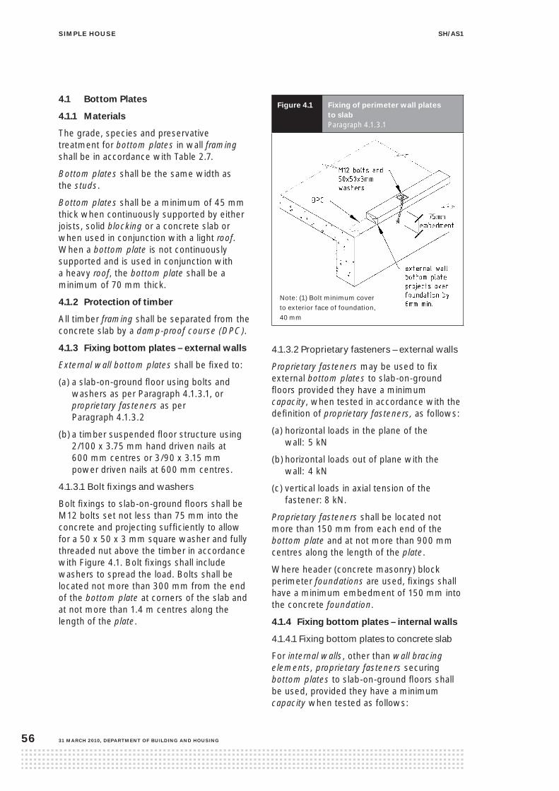
siMple house sh/as1
31 March 2010, DepartMent of BuilDing anD housing56
4.1 Bottom plates
4.1.1 Materials
The grade, species and preservative treatment for bottom plates in wall framing shall be in accordance with Table 2.7.
Bottom plates shall be the same width as the studs.
Bottom plates shall be a minimum of 45 mm thick when continuously supported by either joists, solid blocking or a concrete slab or when used in conjunction with a light roof. When a bottom plate is not continuously supported and is used in conjunction with a heavy roof, the bottom plate shall be a minimum of 70 mm thick.
4.1.2 protection of timber
All timber framing shall be separated from the concrete slab by a damp-proof course (DPC).
4.1.3 fixing bottom plates – external walls
External wall bottom plates shall be fixed to:
(a) a slab-on-ground floor using bolts and washers as per Paragraph 4.1.3.1, or proprietary fasteners as per Paragraph 4.1.3.2
(b) a timber suspended floor structure using 2/100 x 3.75 mm hand driven nails at 600 mm centres or 3/90 x 3.15 mm power driven nails at 600 mm centres.
4.1.3.1 Bolt fixings and washers
Bolt fixings to slab-on-ground floors shall be M12 bolts set not less than 75 mm into the concrete and projecting sufficiently to allow for a 50 x 50 x 3 mm square washer and fully threaded nut above the timber in accordance with Figure 4.1. Bolt fixings shall include washers to spread the load. Bolts shall be located not more than 300 mm from the end of the bottom plate at corners of the slab and at not more than 1.4 m centres along the length of the plate.
figure 4.1 fixing of perimeter wall plates to slab Paragraph 4.1.3.1
4.1.3.2 Proprietary fasteners – external walls
Proprietary fasteners may be used to fix external bottom plates to slab-on-ground floors provided they have a minimum capacity, when tested in accordance with the definition of proprietary fasteners, as follows:
(a) horizontal loads in the plane of the wall: 5 kN
(b) horizontal loads out of plane with the wall: 4 kN
(c) vertical loads in axial tension of the fastener: 8 kN.
Proprietary fasteners shall be located not more than 150 mm from each end of the bottom plate and at not more than 900 mm centres along the length of the plate.
Where header (concrete masonry) block perimeter foundations are used, fixings shall have a minimum embedment of 150 mm into the concrete foundation.
4.1.4 fixing bottom plates – internal walls
4.1.4.1 Fixing bottom plates to concrete slab
For internal walls, other than wall bracing elements, proprietary fasteners securing bottom plates to slab-on-ground floors shall be used, provided they have a minimum capacity when tested as follows:
Note: (1) Bolt minimum cover
to exterior face of foundation,
40 mm

siMple housesh/as1
DepartMent of BuilDing anD housing, 31 March 2010 57
(a) in the plane of the wall: 4 kN
(b) out of the plane of the wall: 3 kN.
Proprietary fasteners to internal walls shall be within 150 mm of each end of the plate and at not more than 900 mm centres elsewhere.
4.1.4.2 Fixing internal bottom plates to timber floor framing
Internal bottom plates shall be fixed to the timber floor framing by:
(a) 1/100 x 3.75 mm hand driven nail at 600 mm centres, or
(b) 1/90 x 3.15 mm power driven nail at 600 mm centres.
4.1.5 Bottom plates generally
4.1.5.1 Where holes or face notches exceed 50% of the width of the bottom plate, fix the plate against sideways movement on each side of the hole or notch using:
(a) on concrete floors, a proprietary fastener of 3kN capacity in and out of plane of the wall
(b) on timber suspended floors, 1/100 x 3.75 mm nails.
4.1.5.2 Perimeter bottom plates shall overhang a concrete foundation by 6 mm.
4.2 studs
4.2.1 general
4.2.1.1 The grade, species and preservative treatment for studs in wall framing shall be in accordance with Table 2.7.
4.2.1.2 Studs shall be 2.4 m maximum length generally (excluding gable end or raking internal walls), and 90 x 45 mm with a maximum stud spacing of 480 mm.
Where the simple house is in a wind zone shown to be less than Very High, the stud spacing may be increased, as an option, up to 600 mm in accordance with Table 4.1.
Comment: The simple house is applicable to all areas of New Zealand up to and including Very High wind zones, with specific exclusions in accordance with Paragraph 2.2.
Where a simple house is to be sited in a wind zone less than Very High (i.e. up to a maximum of 44 metres per second) and the designer chooses to increase the stud spacing as per Paragraph 4.2.1.2, they will need to demonstrate what that lesser wind zone is. The calculation shall be in accordance with Section 5 of NZS 3604, or the BCA may have wind zones already identified for the given site on their own locality maps.
When stud spacings are increased to 600 mm with heavy roofs, the maximum loaded dimension for the wall shall be 3.7 m.
4.2.2 gable end
Where longer studs are required they shall be sized as in Table 4.1.
table 4.1 studs in external, gable and internal walls Paragraphs 4.2.1 and 4.2.2
Maximum height of
stud (m)
All wind zones – stud size (mm x mm)
and max stud centres (mm)
Wind zones up to and including High –
stud size (mm x mm) and max stud centres (mm)
External walls
2.4 90 x 45 at 480 centres 90 x 45 at 600 centres
3.0 2/90 x 45 at 600 centres 2/90 x 45 at 600 centres
3.6 140 x 45 at 480 centres 140 x 45 at 480 centres
4.0 2/140 x 45 at 400 centres or 190 x 45 at 600 centres 2/140 x 45 at 480 centres or 190 x 45 at 600 centres
Internal walls All wind zones
3.0 90 x 45 at 600 centres
3.6 2/90 x 45 at 600 centres
4.0 2/90 x 45 at 400 centres or 140 x 45 at 600 centres

siMple house sh/as1
31 March 2010, DepartMent of BuilDing anD housing58
4.2.3 Wall junctions
Wall junctions shall be framed up with 3 studs blocked and nailed.
4.2.4 notches and holes
Holes in the face and notches in the edge of a stud (see Figure 4.2) shall:
(a) be placed anywhere over the face of the stud except that:
(i) in masonry veneer cladding, holes shall be at least 50 mm clear of the outside face of the stud supporting the veneer
(ii) for trimming studs refer to Paragraph 4.2.6.2
(b) be no greater in diameter or depth than 25 mm. This may be increased to 35 mm where not more than three consecutive studs are drilled or notched
(c) for notches in studs, be spaced vertically not less than 600 mm apart, irrespective of the edge containing the notch.
figure 4.2 notches and holes Paragraph 4.2.4
4.2.5 stud straightness
Timber to be used as a stud shall not have a crook exceeding 10 mm.
4.2.6 trimming studs
4.2.6.1 A trimming stud shall be provided to each side of any opening that includes a lintel (see Figure 4.3 and Table 4.2).
4.2.6.2 Trimming studs, whether single, double or quadruple, shall not contain holes, notches, checks or cuts in the middle third of their length, shall have the same width as the studs in the wall and shall have the thickness given by Table 4.2.
4.2.6.3 Where a doubling stud (see Figure 4.3) which provides support for a lintel is shorter by 400 mm or more than the full stud height, its thickness shall not be included as contributing to the thickness of trimming studs from Table 4.2.
table 4.2 trimming studsParagraph 4.2.6
Maximum clear width of
opening (span of lintel) (m)
Thickness of trimming
stud (mm)
Up to 1.8 45
1.8 to 3.7 90
3.7 to 4.8 (garage doors only)
180

siMple housesh/as1
DepartMent of BuilDing anD housing, 31 March 2010 59
figure 4.3 trimming studs and lintels Paragraphs 4.2.6 and 4.5
4.2.7 lateral support of studs
All studs shall be laterally supported by dwangs.

siMple house sh/as1
31 March 2010, DepartMent of BuilDing anD housing60
4.3 Dwangs
4.3.1 The grade, species and preservative treatment for dwangs in wall framing shall be in accordance with Table 2.7.
Dwangs shall be a minimum of 90 x 45 mm, and spaced at not more than 1.35 m centre-to-centre.
4.3.2 Dwangs for the support of cladding or lining shall be flush with the face of the studs.
4.4 top plates
4.4.1 loadbearing walls
The grade, species and preservative treatment for top plates in wall framing shall be in accordance with Table 2.7.
Top plates to loadbearing walls shall be a lamination of 90 x 45 mm plus 140 x 35 mm, or two equal sized laminations, each being 90 x 45 mm minimum. Where wider studs are used, the laminations of the top plate shall be at least the same width as the studs. The lower lamination shall be a minimum of 45 mm thick and the upper lamination a minimum of 140 x 35 mm.
CommentThe wider upper lamination also serves as a perimeter ceiling batten.
4.4.2 non-loadbearing walls
Top plates of non-loadbearing walls shall be the same width as the studs and no less than 35 mm thick.
4.4.3 Joints in plates
4.4.3.1 In-line joints in top plates of walls shall be made only over supports being either a stud or blocking in accordance with Figure 4.4.
4.4.3.2
(a) For top plates connected over a stud, use a 75 x 1 mm (minimum thickness) metal nail plate of 300 mm minimum length with 6/30 x 3.15 mm nails per side or a proprietary fastener with a capacity in tension and compression of 6 kN.
(b) For top plates supported over solid blocking, the top plates shall be connected to the solid blocking using a minimum of 6/100 x 3.75 mm nails per side or a proprietary fastener with a capacity in tension and compression of 6 kN.

siMple housesh/as1
DepartMent of BuilDing anD housing, 31 March 2010 61
figure 4.4 connecting top plates Paragraph 4.4.3
figure 4.5 connecting top plates to external walls at right angles – walls containing bracing Paragraph 4.4.3.3
4.4.3.3 Each wall that contains one or more wall bracing elements shall be connected at top plate level, either directly or through a framing member in the line of the wall, to external walls at right angles to it. Top plate fixing(s) of the capacity in tension or compression along the line of the wall bracing element are given as follows. For each wall containing wall bracing elements with a total bracing capacity of:
(a) not more than 125 bracing units to at least one external wall by a 75 mm x 1 mm (minimum cross section) metal nail plate of 240 mm minimum length with 6/30 x 3.15 mm nails per side in accordance with Figure 4.5 or a proprietary fastener with a capacity in tension and compression of 6 kN

siMple house sh/as1
31 March 2010, DepartMent of BuilDing anD housing62
(b) not more than 250 bracing units to at least two external walls by a 75 mm x 1 mm (minimum cross section) metal nail plate of 240 mm minimum length with 6/30 x 3.15 mm nails per side in accordance with Figure 4.5 or a proprietary fastener each with a capacity in tension and compression of 6 kN
(c) more than 250 bracing units to at least two external walls by proprietary fasteners in accordance with Figure 4.5 each having a rating of not less than 2.4 kN per 100 bracing units.
4.4.4 lateral support of top plates
4.4.4.1 Top plates shall be laterally supported by framing members spaced at not greater than 2.5 m.
4.4.4.2 Where the required framing support is not provided directly by intersecting top plates, rafters, trusses or purlins, then it shall be provided by mimimum 70 x 45 mm connecting members. The members shall run between the top plate and roof framing member that is parallel to the wall under consideration and to which ceiling framing is attached. Such connecting members shall be connected in accordance with Figure 4.6.
4.4.5 holes, notches and slots in top plates
The sizes of holes or notches in top plates shall comply with the dimensions shown in Figure 4.7. Where the size of a hole or notch exceeds these dimensions, the plates shall be strengthened by one of the following methods:
(a) a 70 x 35 mm member x 600 mm long nailed to the exterior side of the plate with 4/75 x 3.15 mm nails on each side of the hole or notch, in accordance with Figure 4.8, or
(b) a 70 x 35 mm eaves bearer connected to all studs and no more than 250 mm below the top plate, or
(c) a 70 x 35 mm blocking fitted between trusses above cut top plates and a 40 x 40 x 1 mm steel angle shown in Figure 4.8.
figure 4.6 connecting members providing lateral support to top plates Paragraph 4.4.4.2

siMple housesh/as1
DepartMent of BuilDing anD housing, 31 March 2010 63
figure 4.7 holes, notches and slots in top plates Paragraph 4.4.5
figure 4.8 strengthening top plates Paragraph 4.4.5
4.4.6 connection of plates to studs
Top plates supporting roof members shall be connected to wall studs or lintels with fixings as given in Table 4.3.
table 4.3 fixing top plates supporting roof members to wall studs or lintels Paragraph 4.4.6
Loaded
dimension
of wall (m)
Fixings Capacity of
proprietary
fastener (kN)
0 – 4.5 2/100 x 3.75 skewed nails + 2 wire dogs
4.7
4.5 – 6.0 2/100 x 3.75 skewed nails + 3 wire dogs
6.7
4.5 openings
4.5.1 lintels for openings
The grade, species and preservative treatment for timber lintels in wall framing shall be in accordance with Table 2.7.
4.5.1.1 Lintels shall be provided over all openings in loadbearing walls (see Figure 4.9).
4.5.1.2 Timber Lintels
Timber lintels shall be of the dimensions given by Table 4.4.

siMple house sh/as1
31 March 2010, DepartMent of BuilDing anD housing64
table 4.4 timber lintels supporting roof only Paragraphs 2.4.3 and 4.5.1
Roofing Loaded
dimension
of lintel (m)
Maximum span for lintel sizes listed below (m)
2/90 x 45 or 90 x 90 mm
2/140 x 45 or 140 x 90 mm
2/190 x 45 or 190 x 90 mm
2/240 x 45 or 240 x 90 mm
2/290 x 45 or 290 x 90 mm
Profile metal or metal tile 3 1.1 1.8 2.5 3.1 3.7
4 1.0 1.6 2.3 2.9 3.2
5 1.0 1.5 2.1 2.7 2.7
6 0.9 1.5 2.0 2.2 2.2
Masonry tile 3 0.9 1.4 2.0 2.5 3.0
4 0.8 1.3 1.8 2.3 2.8
5 0.8 1.2 1.7 2.2 2.6
6 0.7 1.2 1.6 2.0 2.5
Note:
1. 2/45 thick members shall be laminated in accordance with Paragraph 2.7.3.
2. For lintels supporting roofs with 1 kPa snow load the span shall be multiplied by a factor of 0.8.
figure 4.9 lintel supporting roof only Paragraph 4.5.1 and Table 4.4
4.5.1.3 Timber lintels shall be supported at each end for the full thickness of the lintel by the minimum seating dimensions of (see Figure 4.10):
(a) for lintels not exceeding 140 mm deep: a trimming stud checked not less than 15 mm, nor more than 20 mm
(b) for lintels not exceeding 240 mm deep: a 35 mm thick doubling stud
(c) for lintels not exceeding 290 mm deep: a 45 mm thick doubling stud.
4.5.1.4 Timber lintels supporting rafters or trusses of roofs shall be secured against uplift at each end in accordance with Figure 4.10 or with a proprietary fastener of 7.5 kN capacity in tension along the line of the trimming stud.

siMple housesh/as1
DepartMent of BuilDing anD housing, 31 March 2010 65
figure 4.10 fixing of lintels to prevent uplift Paragraphs 4.5.1.3, 4.5.1.4 and Table 4.5

siMple house sh/as1
31 March 2010, DepartMent of BuilDing anD housing66
4.5.1.5 Steel lintels (garage door only)
Steel lintels shall be connected directly to the underside of the top plate and shall be in walls with a maximum 2.4 m height of studs. Steel lintels are not permitted in gable or mono-pitch walls.
4.5.1.6 Steel lintels shall be hot rolled 200 x 75 mm Parallel Flange Channel sections with a maximum clear opening of up to 4.8 m and a maximum loaded dimension of 4.0 m.
4.5.1.7 Steel lintels shall be secured against uplift at each end in accordance with Figure 4.11 or with a proprietary fastener of 12 kN capacity in tension along the line of the trimming studs. The top plate shall be secured to the top of the garage door lintel with M12 bolts at 600 mm centres maximum.
4.5.1.8 Steel lintels shall be supported at each end by 4/90 x 45 mm studs in accordance with Figure 4.11.
4.5.1.9 For steel lintel cladding details, refer to Paragraph 6.7.

siMple housesh/as1
DepartMent of BuilDing anD housing, 31 March 2010 67
figure 4.11 steel lintels, trimming studs and prevent of uplift Paragraphs 4.5.1.5 to 4.5.1.8

siMple house sh/as1
31 March 2010, DepartMent of BuilDing anD housing68
4.5.2 sill and head trimmers
4.5.2.1 Sill and head trimmers to openings in non-loadbearing walls shall be of the same width as the studs and of the depth given by Table 4.5.
table 4.5 sill and head trimmersParagraph 4.5.2.1
Maximum clear width
of opening (m)
Minimum depth of sill
and head trimmers (mm)
2.4 45
3.0 90
3.7 140
4.6 Wall bracing
4.6.1 Wall bracing demand
Wall bracing shall be designed and constructed in accordance with this paragraph to resist the bracing demand for the greater of wind or earthquake (not acting together) determined from Paragraphs 4.6.1.1 and 4.6.1.2.
4.6.1.1 Wind bracing demand
The overall wind bracing demand on the simple house in both directions shall be determined by multiplying the value obtained from Table 4.6 by the simple house (or roof ) length, where length is measured perpendicular to the direction of the wind (see Figure 4.12). The simple house length shall be used where the roof pitch is 25° or less, and the roof length where the roof pitch is greater than 25°.
table 4.6 Bracing demand for wind (Bus/m)Paragraph 4.6.1.1
Height of ridge above
eaves (h) in metres
Across ridge Along ridge
1 44 63
2 69 81
3 100 100

siMple housesh/as1
DepartMent of BuilDing anD housing, 31 March 2010 69
figure 4.12 Direction of wind and braced wallsParagraphs 3.3.12.1 and 4.6.1.1
4.6.1.2 Earthquake bracing demand
The overall earthquake bracing demand on the simple house, in both the length and width directions of the simple house, shall be determined by multiplying the values in Table 4.7 by the gross floor area in square metres.
table 4.7 Bracing demand for walls (Bus/m2) Paragraph 4.6.1.2
Cladding Roof Roof pitch degrees BUs/m² of floor area
(walls over subfloor
framing)
BUs/m² of floor area
(walls over concrete
slab-on-ground)
Weatherboard, flat sheet
Profiled metal or metal tile 10–25 6.7 3.6
26–35 7.1 4.0
Masonry veneer Profiled metal or metal tile 10–25 11.6 5.2
26–35 12.1 5.6
Weatherboard, flat sheet
Masonry tile 10–25 9.8 6.3
26–35 11.0 7.5
Masonry veneer Masonry tile 10–25 14.9 7.9
26–35 16.3 9.1
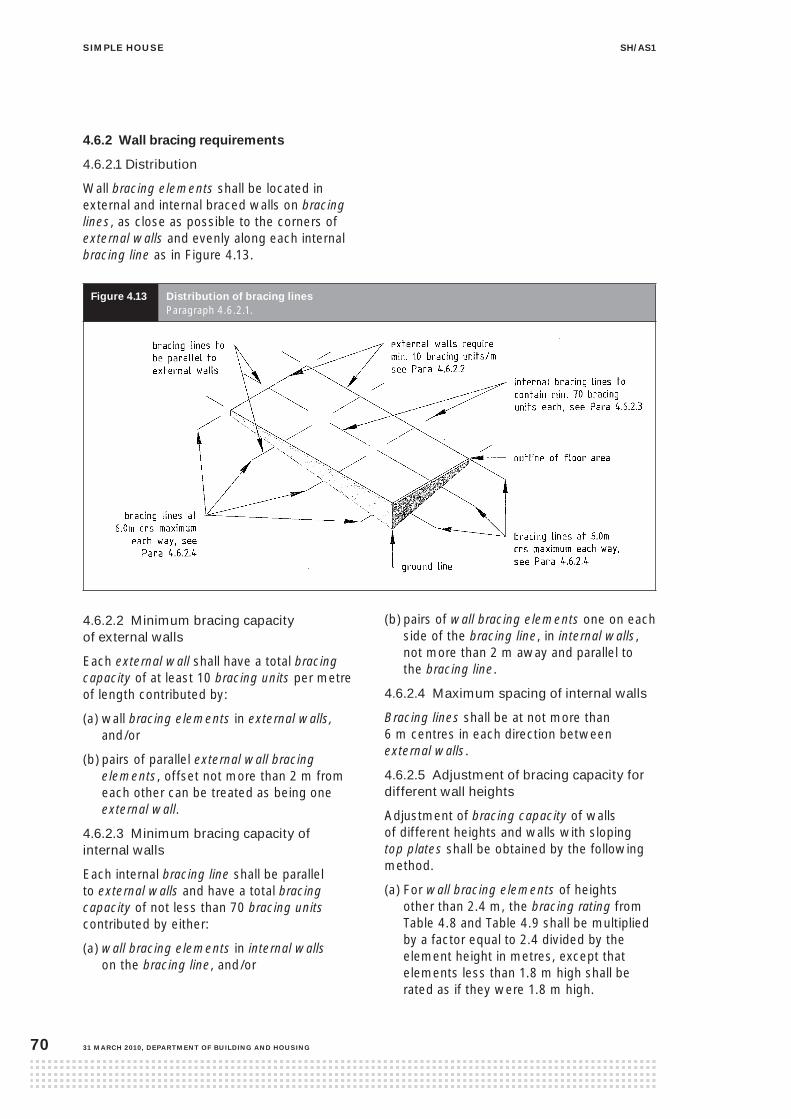
siMple house sh/as1
31 March 2010, DepartMent of BuilDing anD housing70
4.6.2 Wall bracing requirements
4.6.2.1 Distribution
Wall bracing elements shall be located in external and internal braced walls on bracing lines, as close as possible to the corners of external walls and evenly along each internal bracing line as in Figure 4.13.
figure 4.13 Distribution of bracing lines Paragraph 4.6.2.1.
4.6.2.2 Minimum bracing capacity of external walls
Each external wall shall have a total bracing capacity of at least 10 bracing units per metre of length contributed by:
(a) wall bracing elements in external walls, and/or
(b) pairs of parallel external wall bracing elements, offset not more than 2 m from each other can be treated as being one external wall.
4.6.2.3 Minimum bracing capacity of internal walls
Each internal bracing line shall be parallel to external walls and have a total bracing capacity of not less than 70 bracing units contributed by either:
(a) wall bracing elements in internal walls on the bracing line, and/or
(b) pairs of wall bracing elements one on each side of the bracing line, in internal walls, not more than 2 m away and parallel to the bracing line.
4.6.2.4 Maximum spacing of internal walls
Bracing lines shall be at not more than 6 m centres in each direction between external walls.
4.6.2.5 Adjustment of bracing capacity for different wall heights
Adjustment of bracing capacity of walls of different heights and walls with sloping top plates shall be obtained by the following method.
(a) For wall bracing elements of heights other than 2.4 m, the bracing rating from Table 4.8 and Table 4.9 shall be multiplied by a factor equal to 2.4 divided by the element height in metres, except that elements less than 1.8 m high shall be rated as if they were 1.8 m high.

siMple housesh/as1
DepartMent of BuilDing anD housing, 31 March 2010 71
(b) Walls of varying heights shall have their bracing capacity adjusted in accordance with Paragraph 4.6.2.5 (a) using the average height.
4.6.2.6 Braced walls at angles
Where braced walls are at angles to the bracing lines, the braced walls shall contribute to the bracing as follows:
(a) 30º to one direction and 60º in the other direction, 0.87 and 0.5 times the value of the wall bracing capacity respectively
(b) 45º to both directions, 0.7 times the value of the wall bracing capacity
(c) values for other angles shall be obtained by multiplying the bracing capacity of the element by the cosine of the angle between the bracing element and the bracing line being considered.
4.6.3 Wall bracing systems
Use any of the following three wall bracing systems: proprietary BRANZ P21 Tested under Paragraph 4.6.3.1, plasterboard under Paragraph 4.6.3.2, or plywood systems under Paragraph 4.6.3.3.
4.6.3.1 Proprietary wall bracing element capacity
The bracing capacity of wall bracing elements to provide wall resistance to horizontal loads shall be the bracing capacity of a proprietary system determined by the BRANZ P21 Test procedure and the BRANZ supplement to P21 rating procedure.
Where proprietary wall bracing elements are used, the uplift capacity of the hold-down fixings shall be the greater of that required by the P21 test on the wall bracing element or a proprietary fastening of 8 kN capacity fixed in accordance with Paragraph 4.1.3 for external walls or Paragraph 4.1.4 for internal walls.
4.6.3.2 Plasterboard (non P21 Test option)
2.4 m high plasterboard bracing elements shall have the bracing capacities assigned in Table 4.8 and be fixed in accordance with the details in Figure 4.14. Plasterboard shall:
(a) be manufactured in accordance with AS/NZS 2588
(b) have a minimum width of 0.9 m
(c) have a minimum manufactured sheet length 2.4 m
(d) have a minimum density of 450 kg/m3
(e) have a minimum thickness of 9 mm
(f) be installed vertically to the full height of the bracing element or horizontally with maximum of one joint in the bracing element
(g) be fixed to framing with 30 x 2.5 mm flat head nails, or 32 mm x 7 g zinc-plated screws or, where plasterboard is thicker than 10 mm, the nailing option shall be with nail lengths three times the plasterboard thickness
(h) have fixings no closer than 12 mm to bound paper edge and 18 mm to the cut edge
(i) have sheet corner fixings as per Figure 4.14.
table 4.8 Bracing values for plasterboard bracing systems Paragraph 4.6.2.5 and 4.6.3.2
Length (m) Plasterboard sheet one side – BUs/m Plasterboard sheet both sides – BUs/m
Wind Earthquake Wind Earthquake
1.2 30 25 45 40
1.8 45 40 65 55
2.4 55 50 75 65

siMple house sh/as1
31 March 2010, DepartMent of BuilDing anD housing72
figure 4.14 plasterboard bracing systems Paragraph 4.6.3.2

siMple housesh/as1
DepartMent of BuilDing anD housing, 31 March 2010 73
4.6.3.3 Plywood bracing system (non P21 Test option)
2.4 m high plywood bracing elements shall not be used as cladding (see Paragraph 6.5.2.1) and shall have the bracing capacities assigned in Table 4.9 and be fixed in accordance with the details in Figure 4.15. Plywood shall:
(a) be to the grade, species and preservative treatment in accordance with Table 2.7
(b) have a minimum manufactured width of 0.9 m
(c) have a minimum manufactured sheet length of 2.4 m
(d) be installed vertically
(e) be three ply with a minimum thickness of 7 mm and a maximum of 12 mm
(f) be fixed to framing with fixings no closer than 10 mm to sheet edge
(g) be fixed at corners in accordance with Figure 4.15
(h) be fixed to framing members with 30 x 2.8 mm flat head nails. Where plywood is 9 mm, use 40 x 2.5 mm flat head nails and, where 12 mm thick, use 50 x 2.5 mm flat head nails.
table 4.9 Bracing values for plywood bracing systems Paragraph 4.6.2.5 and 4.6.3.3
Length (m) Plywood fixed one side – BUs/m
Wind Earthquake
0.9 70 65
1.8 85 80

siMple house sh/as1
31 March 2010, DepartMent of BuilDing anD housing74
figure 4.15 plywood bracing systems Paragraph 4.6.3.3

siMple housesh/as1
DepartMent of BuilDing anD housing, 31 March 2010 75
4.7 linings
4.7.1 Barriers to airflow
This Acceptable Solution requires that habitable spaces have barriers to airflow in the form of interior linings with all joints stopped. Refer also to Paragraphs 6.1.1 and 6.1.2.
4.8 nailing schedule
Table 4.10 lists the size, number and location of nails to be used in wall framing. The depth of penetration into the point side timber shall be at least 45% of the length of the nail.
table 4.10 size, number and location of nails for fixing timber Paragraph 4.8
Joint Hand driven nails Power driven nails
Length (mm) x diameter (mm) and type
Number and location
Length (mm) x diameter (mm) and type
Number and location
Dwang to stud 75 x 3.5 or 100 x 3.75
2 (skewed) 2 (end nailed)
75 x 3.06 or 90 x 3.15
2 (skewed) 2 (end nailed)
Lintel to trimming stud 75 x 3.15 or 100 x 3.75
4 (skewed) or 2 (end nailed)
90 x 3.15 3 (end nailed)
Sill or head trimmer to trimming stud (max 2.4 m long)
100 x 3.75 2 (end nailed) 90 x 3.15 3 (end nailed)
Sill or head trimmer to trimming stud (max 3.6 m long)
100 x 3.75 3 (end nailed) 90 x 3.15 5 (end nailed)
Stud to plate 100 x 3.75 or 75 x 3.15
2 (end nailed) 4 (skewed)
75 x 3.06 90 x 3.15
4 (skew nailed) 3 (end nailed)
Top plate 140 x 35 mm to 90 x 45 mm and top plate to lintel
100 x 3.75 2 at 500 mm centres
90 x 3.15 90 x 3.15
3 at 500 mm centres
Trimming studs at openings, blocking and studs at wall intersections
100 x 3.75 600 mm centres 90 x 3.15 90 x 3.15
600 mm centres
Trimming stud to doubled stud immediately under lintel
100 x 3.75 2 90 x 3.15 2
Note:
Nail lengths and diameters are the minimum required.
Refer to Paragraph 2.5.4 for required protective coatings for metal fasteners.
4.9 construction moisture in timber
4.9.1 Maximum acceptable moisture contents in timber
The maximum moisture contents shall be:
(a) for timber framing, 20% at the time of installing interior linings
(b) for timber weatherboards and exterior joinery, 20% at the time of painting
(c) for reconstituted wood products, 18% at all times.

siMple house sh/as1
31 March 2010, DepartMent of BuilDing anD housing76
contents
5.1.1 Scope
5.1.2 Eaves
5.1.3 Gable verges
5.1.4 Purlins and tile battens
5.1.5 Bracing
5.1.6 Roof plane diagonal brace
5.1.7 Roof space diagonal brace
5.1.8 Bottom chord fixings
5.1.9 Nailing schedule for roofs
figures
5.1.1 Roof types
5.1.2 Gable verge framing
5.1.3 Periphery roof areas – gable
5.1.4 Periphery roof areas – hip/valley
5.1.5 Purlins fixed directly to rafters/top chords
5.1.6 Roof plane diagonal brace
5.1.7 Roof space diagonal brace
tables
5.1.1 Purlin and tile batten size, span, spacings and fixing capacity and type
5.1.2 Fixings for purlins or battens
5.1.3 Nailing schedule for hand driven and power driven nails
5.1.1 scope
5.1.1.1 Roofs shall be either framed on site or constructed from prefabricated trusses.
5.1.1.2 The grade, species and preservative treatment for roof framing shall be in accordance with Table 2.7.
5.1.1.3 Framed roofs shall be skillion roofs in accordance with Figure 5.1.1.
Skillion roofs shall not incorporate valleys or hips.
5.1.2 eaves
5.1.2.1 A rafter or truss may extend as a cantilever beyond its supporting top plate for a distance not exceeding one quarter of its maximum permitted span, or 750 mm measured horizontally from the face of the support, whichever is the lesser. Where 90 x 45 mm rafters are supported by eaves bearers (boxed), they may extend to 750 mm.
5.1.2.2 Within boxed eaves, the eaves bearers shall be attached to the ends of rafters or trusses and to studs or ribbon boards at not more than 1200 mm centres.
5.1.2.3 Eaves bearers shall be:
(a) 45 x 35 mm timber not exceeding 600 mm long
(b) 70 x 35 mm timber not exceeding 750 mm long.
5.1.3 gable verges
5.1.3.1 Gable verges shall be framed by either:
(a) outriggers complying with Paragraph 5.1.3.3 and in accordance with Figure 5.1.2, or
(b) purlins extending as cantilevers beyond their end supports in accordance with Figure 5.1.2 for a distance not exceeding that given by Paragraph 5.1.3.2.
5.0 roof framing
5.1 general

siMple housesh/as1
DepartMent of BuilDing anD housing, 31 March 2010 77
figure 5.1.1 roof types Paragraph 5.1.1.3

siMple house sh/as1
31 March 2010, DepartMent of BuilDing anD housing78
figure 5.1.2 gable verge framing Paragraph 5.1.3
siMple housesh/as1
DepartMent of BuilDing anD housing, 31 March 2010 79
5.1.3.2 Purlins and battens supporting roof claddings, with a back span over at least 3 rafters or trusses may extend as cantilevers beyond their end supports for a distance not exceeding:
(a) laid on their flat:
(i) light roofs
50 x 50 mm battens: 300 mm
70 x 45 mm purlins: 500 mm
90 x 45 mm purlins: 600 mm
(ii) heavy roofs
50 x 50 mm battens at 400 mm crs: 300 mm
70 x 45 mm purlins at 400 mm crs: 400 mm
95 x 45 mm purlins at 400 mm crs: 500 mm
(b) laid on their edge:
(i) light roofs
70 x 45 mm purlins: 600 mm
90 x 45 mm purlins: 700 mm
(ii) heavy roofs
70 x 45 mm purlins at 400 mm crs: 500 mm
95 x 45 mm purlins at 400 mm crs: 600 mm.
5.1.3.3 Outriggers shall:
(a) be laid on edge
(b) be a minimum size of 90 x 45 mm
(c) be located at not more than 900 mm centres
(d) extend beyond their supports for a distance not exceeding 600 mm
(e) have a flying rafter, minimum size 90 x 45 mm, fixed to their ends
(f) have blocking pieces of the same size as the outriggers fitted and fixed between the outriggers along the line of the end support. Purlins shall be fixed to the blocking piece and to the flying rafter
(g) be fixed to wall framing with fixings determined from Table 5.1.1, as if the outriggers are purlins.
5.1.4 purlins and tile battens
5.1.4.1 The grade, species and preservative treatment for purlins and tile battens shall be in accordance with Table 2.7.
5.1.4.2 The size of purlins and their fixings shall be taken from Table 5.1.1 and Table 5.1.2 using spacing to suit the spanning capability of the cladding.
Periphery areas as per Table 5.1.1 are as shown shaded in Figures 5.1.3 and 5.1.4.
5.1.4.3 The size of tile battens and their fixings shall be taken from Table 5.1.1 and Table 5.1.2 using spacing to suit the spanning capabilities of the tile. Periphery (shaded) areas shall be in accordance with Figures 5.1.3 and 5.1.4.

siMple house sh/as1
31 March 2010, DepartMent of BuilDing anD housing80
table 5.1.1 purlin and tile batten size, span, spacing and fixing capacity and typeParagraphs 5.1.3.3, 5.1.4.2, 5.1.4.3, 5.1.4.5, 5.1.9.1 and Table 5.1.3
Size
(mm x mm)
Max span
(mm)
Max
Spacing
(mm)
Fixing – main roof Fixing – periphery
(refer to Paragraph
5.1.4.3)
Capacity
(kN)
Type
Table
5.1.2
Capacity
(kN)
Type
(refer
to Table
5.1.2)
Purlin
70 x 45 900 900 1.3 C 2.0 C
70 x 45 900 1200 1.8 C 2.6 C
70 x 45 900 1400 2.0 C 3.1 D
70 x 45 1200 800 1.6 C 2.3 C
90 x 45 1200 1000 2.0 C 2.9 D
Battens for metal tiles
50 x 40 900 400 0.7 B 1.0 C
50 x 50 1200 400 0.9 C 1.3 C
Battens for masonry tiles
50 x 25 480 400 0.4 A 0.4 A
50 x 40 600 400 0.4 A 0.4 A
50 x 50 900 400 0.4 A 0.4 A
table 5.1.2 fixings for purlins or battensParagraphs 5.1.4.2, 5.1.4.3, 5.1.9.1 and Table 5.1.3
Fixing description Type
1/100 x 3.75 mm nail or 1/90 x 3.15 mm power driven nail A
2/100 x 3.75 mm skewed nails or 2/90 x 3.15 mm power driven nails B
2/100 x 3.75 mm skewed nails + 1 wire dog or 2/100 x 3.75 mm skewed nails + 1/14 g Type 17 screw to AS 4566 C
2/100 x 3.75 mm skewed nails + 2 wire dogs or 2/100 x 3.75 mm skewed nails + 2/14 g Type 17 screws to AS 4566 D
If screw fixed, screws shall be sufficiently long so as to penetrate rafter by at least 50 mm.

siMple housesh/as1
DepartMent of BuilDing anD housing, 31 March 2010 81
figure 5.1.3 periphery roof areas – gable Paragraphs 5.1.4.2 and 5.1.4.3
figure 5.1.4 periphery roof areas – hip/valley Paragraphs 5.1.4.2 and 5.1.4.3
5.1.4.4 Purlins and tile battens shall be laid directly over rafters and truss top chords, parallel to the associated ridge or eaves line in accordance with Figure 5.1.5.
5.1.4.5 All purlin sizes given in Table 5.1.1 are on-flat. 70 x 45 mm on-flat may be substituted by 70 x 45 mm on edge, and 90 x 45 mm on-flat may be substituted by 70 x 45 mm on edge.
figure 5.1.5 purlins fixed directly to rafters/top chords Paragraph 5.1.4.4

siMple house sh/as1
31 March 2010, DepartMent of BuilDing anD housing82
5.1.4.6 Purlins and tile battens shall be continuous over at least two spans, and may be butt jointed over supports provided that no two adjacent purlins or tile battens are jointed over the same truss or rafter.
5.1.5 Bracing
5.1.5.1 Light roofs
Each ridge line and its associated trusses or rafters shall be braced by not less than:
(a) three hip or valley trusses running clear from the ridge line to the top plate of a loadbearing wall, or
(b) one roof plane diagonal brace complying with Paragraph 5.1.6.1 in each plane of the roof for each 50 m², or part there of of plan area of that plane.
5.1.5.2 Heavy hip roofs
Each ridge line and its associated trusses shall be braced by:
(a) not less than three hip or valley trusses running clear through from the ridge line to the top plate of a loadbearing wall, and
(b) one roof plane diagonal brace complying with Paragraph 5.1.6.1 in each side plane of the roof for each 35 m² or part thereof of plan area of that plane.
5.1.5.3 Heavy gable roof
Each ridge line and its associated rafters or trusses shall be braced by:
(a) one roof plane diagonal brace complying with Paragraph 5.1.6.1 in each plane of the roof for each 25 m² or part thereof of plan area of each roof plane, and for trussed roofs
(b) one roof space diagonal brace, complying with Paragraph 5.1.7.1, for each 12 m² or part thereof of the plan area of each roof plane.
5.1.5.4 L-shaped roofs
For L-shaped roofs with ridge lines at right angles to each other, the valley or hip formed between two roof planes may be counted as forming a roof plane diagonal brace for each roof plane. Refer to Paragraphs 5.1.5.1(b), 5.1.5.2(b) or 5.1.5.3(b) above.
5.1.6 roof plane diagonal brace
5.1.6.1 Each roof plane diagonal brace shall be a diagonally opposing pair of continuous steel strips each having a capacity of 8.0 kN in tension, fixed from ridge to top plate at 45º to ridge and fixed to each top chord or rafter that is intersected, with nailing to Table 5.1.3.
5.1.6.2 When only one roof plane diagonal brace is required in accordance with Paragraph 5.1.5.1(b), this shall intersect one end of the ridge line. Where more than one roof plane diagonal brace is required, a brace shall intersect each end of the ridge line and any remaining braces shall be evenly distributed along the ridge.

siMple housesh/as1
DepartMent of BuilDing anD housing, 31 March 2010 83
figure 5.1.6 roof plane diagonal brace Paragraph 5.1.6
5.1.7 roof space diagonal brace
5.1.7.1 Roof space diagonal braces (refer to Figure 5.1.7) shall:
(a) be not less than 2 m from a parallel external wall, provided that at least half of all such braces shall be not more than 2 m from the ridge line
(b) be evenly distributed over the length of the roof and run alternately in opposite directions
(c) run not steeper than 45° to the horizontal from top chord level to bottom chord level
(d) in plan view be parallel to or at not more than 25° to the ridge line
(e) consist of:
(i) 90 x 45 mm up to 1.85 m long, or
(ii) 2/90 x 45 mm for spans up to 4.8 m. Where two members are required they shall be spaced 45 mm apart and nailed together through the spacing pieces at centres not exceeding 1 m.

siMple house sh/as1
31 March 2010, DepartMent of BuilDing anD housing84
figure 5.1.7 roof space diagonal brace Paragraph 5.1.7
5.1.7.2 The top end of each roof space diagonal brace shall be fixed to a 90 x 45 mm blocking piece fixed between adjacent top chords with 3/100 x 3.75 mm nails to each side. Blocking to be fixed to the top chords with 2/100 x 3.75 mm nails to each end.
5.1.7.3 The bottom end of each roof space diagonal brace shall be fixed to a 70 x 45 mm brace runner with 3/100 x 3.75 mm nails to each side. The runner shall be fixed to not less than two bottom chords on each side of the diagonal brace with 2/100 x 3.75 mm nails to each bottom chord, and be within 300 mm centre-to-centre of a wall containing a wall bracing element.
5.1.8 Bottom chord fixings
The bottom chord of a truss that crosses an internal wall containing one or more wall bracing element shall be connected to the top plate of the wall, either directly, or by a ceiling batten running parallel to the plate and fixed to both the plate and the bottom chord. For fixing, refer to Table 5.1.3.
5.1.9 nailing schedule for roofs
5.1.9.1 Table 5.1.3 lists the size, number and location of nails to be used in roof framing. Refer also to Tables 5.1.1 and 5.1.2 for further specific fixing details and requirements. The depth of penetration into the point side timber shall be at least 45% of the length of the nail.

siMple housesh/as1
DepartMent of BuilDing anD housing, 31 March 2010 85
table 5.1.3 nailing schedule for hand driven and power driven nails Paragraphs 5.1.6.1, 5.1.8 and 5.1.9
Joint Hand driven nails Power driven nails
Length (mm) x
diameter (mm)
and type
Number
and location
Length (mm) x
diameter (mm)
and type
Number
and location
Truss or rafter to top plate of internal wall 100 x 3.75 2 90 x 3.15 2
Ceiling batten to parallel top plate of internal wall bracing element
75 x 3.15 2 at 400 mm centres
90 x 3.15 2 at 400 mm centres
Steel strip brace: (i) at ends (ii) other cases
60 x 3.15 60 x 3.15
3 2
Blocking between rafters or truss chords 100 x 3.75 2 (end nailed) 90 x 3.15 2 (end nailed)
Outrigger to rafter 100 x 3.75 or 75 x 3.15
2 (end nailed) 4 skewed
90 x 3.15 3 (end nailed)
Flying rafter to outrigger 100 x 3.75 2 90 x 3.15 3
Outrigger blocking to top plate 100 x 3.75 4 skewed 90 x 3.15 4 skewed
Outrigger to gable top plate As for purlin (see Tables 5.1.1 and 5.1.2)
As for purlin (see Tables 5.1.1 and 5.1.2)
As for purlin (see Tables 5.1.1 and 5.1.2)
As for purlin (see Tables 5.1.1 and 5.1.2)

siMple house sh/as1
31 March 2010, DepartMent of BuilDing anD housing86
contents
5.2.1 Design and fabrication
5.2.2 Maximum dimensions and spacings
5.2.3 Truss/top plate connections
5.2.4 Truss connection to internal walls
5.2.5 Ceiling framing
5.2.6 Openings in ceilings
5.2.7 Fixing for ceiling members
figures
5.2.1 Truss/top plate connection
5.2.2 Loaded dimension
5.2.3 Ceiling lining supports
tables
5.2.1 Fixing of roof trusses at supports
5.2.2 Nailing to ceiling members
5.2.1 Design and fabrication
Trusses shall be to specific design and the design shall meet the limiting criteria set out in this section.
The grade, species and preservative treatment for roof trusses shall be in accordance with Table 2.7.
5.2.2 Maximum dimensions and spacings
Roof trusses shall meet the following criteria:
(a) the support span of a roof truss shall not exceed 12 m, and
(b) the eaves overhang shall not exceed 750 mm measured horizontally from the face of the support, and
(c) truss spacings for profiled metal or metal tile roofs shall not exceed 1.2 m, and
(d) truss spacings for masonry tile roofs shall not exceed 900 mm.
5.2.3 truss/top plate connections
The fixing of a truss at its support shall be as given by the truss design, but not less than that required in Table 5.2.1 and Figure 5.2.1. Loaded dimension shall be as shown in Figure 5.2.2.
5.2.4 truss connection to internal walls
When trusses are connected to the top plates of non-loadbearing internal walls as required by Paragraph 5.1.8, install all ceiling framing and roof cladding before connecting trusses. Do not support bottom chords at points other than those designated by the truss manufacturer.
5.2 trusses

siMple housesh/as1
DepartMent of BuilDing anD housing, 31 March 2010 87
table 5.2.1 fixing of roof trusses at supports Paragraph 5.2.3
Loaded dimension
of support (m)
For light roofs Proprietary
fastener capacity
For heavy roofs Proprietary
fastener capacity
3.0 2/100 x 3.75 mm skewed nails + 3 wire dogs
6.7 kN 2/100 x 3.75 mm skewed nails + 2 wire dogs
4.7 kN
3.5 2/100 x 3.75 mm skewed nails + 4 wire dogs
8.7 kN 2/100 x 3.75 mm skewed nails + 2 wire dogs
4.7 kN
4.0 2/100 x 3.75 mm skewed nails + 4 wire dogs
8.7 kN 2/100 x 3.75 mm skewed nails + 2 wire dogs
4.7 kN
4.5 2/100 x 3.75 mm skewed nails + u strap of 25 x 1.2 mm with 10/ 30 x 3.15 mm nails at each end
16.0 kN 2/100 x 3.75 mm skewed nails + 3 wire dogs
6.7 kN
5.0 2/100 x 3.75 mm skewed nails + u strap of 25 x 1.2 mm with 10/ 30 x 3.15 mm nails at each end
16.0 kN 2/100 x 3.75 mm skewed nails + 3 wire dogs
6.7 kN
5.5 2/100 x 3.75 mm skewed nails + u strap of 25 x 1.2 mm with 10/ 30 x 3.15 mm nails at each end
16.0 kN 2/100 x 3.75 mm skewed nails + 3 wire dogs
6.7 kN
6.0 2/100 x 3.75 mm skewed nails + u strap of 25 x 1.2 mm with 10/ 30 x 3.15 mm nails at each end
16.0 kN 2/100 x 3.75 mm skewed nails + 3 wire dogs
6.7 kN

siMple house sh/as1
31 March 2010, DepartMent of BuilDing anD housing88
figure 5.2.1 truss/top plate connection Paragraph 5.2.3

siMple housesh/as1
DepartMent of BuilDing anD housing, 31 March 2010 89
figure 5.2.2 loaded dimension Paragraph 5.2.3
5.2.5 ceiling framing
5.2.5.1 Ceiling linings
Ceiling lining material shall be less than 17.5 kg/m2 and shall be supported from framing timbers as described in Paragraph 5.2.4.
5.2.5.2 Ceiling structure
The framing timbers required for the support of ceiling linings under trussed or skillion roofs shall be any one, or any combination, of:
(a) bottom chords of trusses or bottom edge of rafters
(b) 70 x 45 mm solid blocking on edge, in accordance with Figure 5.2.3, or on flat, at not more than 900 mm centres and spanning between bottom chords or rafters
(c) ceiling battens attached to the underside of bottom chords or rafters.

siMple house sh/as1
31 March 2010, DepartMent of BuilDing anD housing90
5.2.5.3 Ceiling battens shall be 70 x 35 mm at not more than 600 mm centres and spanning up to 1200 mm, or may be proprietary metal ceiling battens.
figure 5.2.3 ceiling lining supports Paragraphs 5.2.5.2 and 5.2.5.3
5.2.6 openings in ceilings
5.2.6.1 Access to the ceiling attic spaces shall be provided via a removable hatch of the same thermal rating as the ceiling, with a minimum clear opening of 600 x 500 mm. Unobstructed access of at least 600 mm in height between the top of the bottom chords and other roof members shall be provided.
5.2.6.2 Openings in ceilings shall be bounded by trimmers and the bottom chord of the truss. Trimmers shall be the same width and thickness as the bottom chord and be fitted between adjacent bottom chords.
5.2.7 fixing of ceiling members
Fixings for ceiling members shall be the minimum shown in Table 5.2.2.
table 5.2.2 nailing to ceiling members Paragraph 5.2.7
Joint Hand driven nails Power driven nails
Length (mm) x
diameter (mm)
Number
and location
Length (mm) x
diameter (mm)
Number
and location
Ceiling batten (70 x 35 mm) to rafter or truss
75 x 3.15 2 75 x 3.06 2
Blocking piece to top plate and truss or rafter
100 x 3.75 4 – 2 each end 90 x 3.15 6 – 3 each end

siMple housesh/as1
DepartMent of BuilDing anD housing, 31 March 2010 91
5.3.1 general
The grade, species and preservative treatment for rafters shall be in accordance with Table 2.7.
5.3.2 rafters
5.3.2.1 Rafters shall span between any two of the following:
(a) top plate
(b) lintel
(c) ridge beam
(d) intermediate beam.
5.3.2.2 Rafters shall be sized from Table 5.3.1. The depth of the rafter shall be at least the depth of the insulation required to satisfy Paragraph 2.8.1 plus 25 mm clearance.
contents
5.3.1 General
5.3.2 Rafters
5.3.3 Ridge and intermediate beams
5.3.4 Purlins and tile battens
figures
5.3.1 Seating of rafters
5.3.2 Fixing rafters – skillion roof
tables
5.3.1 Rafter sizes and spans
5.3.2 Fixing types for rafters
5.3.3 Ridge and intermediate beams
5.3.4 Key to fixing types to restrain ridge/ intermediate beam uplift
5.3 skillion roofs

siMple house sh/as1
31 March 2010, DepartMent of BuilDing anD housing92
table 5.3.1 rafter sizes and spansParagraphs 5.3.2.2 and 5.3.2.4
light roof
Rafter size
(width x thickness)
Maximum span of rafters at a maximum spacing (mm) and their fixing types
600 900 1200
Span Fixing type Span Fixing type Span Fixing type
(mm x mm) (m) (m) (m)
70 X 45 1.4 A 1.2 B – –
90 X 45 1.8 B 1.6 B 1.4 B
140 X 45 2.9 B 2.5 B 2.3 B
190 X 45 3.5 B 3.0 B 2.7 C
240 X 45 3.8 B 3.3 B 3.0 C
290 X 45 4.1 B 3.5 B 3.2 C
90 X 70 2.1 B 1.8 B 1.7 B
140 X 70 3.3 B 2.9 B 2.6 C
190 X 70 4.5 B 3.9 C 3.6 C
240 X 70 5.7 B 5.0 C 4.5 D
290 X 70 6.3 C 5.5 C 5.0 D
heavy roof
Rafter size
(width x thickness)
Maximum span of rafters at a maximum spacing (mm) and their fixing types
600 900
Span Fixing type Span Fixing type
(mm x mm) (m) (m)
70 X 45 1.3 A 1.3 B
90 X 45 1.7 A 1.5 B
140 X 45 2.7 B 2.3 B
190 X 45 3.6 B 3.2 B
240 X 45 4.1 B 3.5 B
290 X 45 4.3 B 3.8 B
90 X 70 2.0 B 1.7 B
140 X 70 3.1 B 2.7 B
190 X 70 4.2 B 3.7 B
240 X 70 5.3 B 4.6 C
290 X 70 6.4 B 5.6 C
Note:
1. For 1.0 kPa snow load the maximum span of rafters to a light or heavy roof are to be multiplied by a factor of 0.85. Refer to Paragraph 2.4.2.
2. Timber members 70 mm thick may be substituted for two 45 mm thick members of the depth specified. Members shall be nailed together with 75 x 3.15 mm hand driven or 90 x 3.15 mm power driven nails at 250 mm centres along length driven alternately from either side (refer to Paragraph 2.7.3).

siMple housesh/as1
DepartMent of BuilDing anD housing, 31 March 2010 93
table 5.3.2 fixing types for raftersParagraph 5.3.2.4
Fixing type Fixing to resist uplift Proprietary
fastener
capacity
(kN)
A 2/100 x 3.75 mm skewed nails
0.7
B 2/100 x 3.75 mm skewed nails + 1 wire dog
2.7
C 2/100 x 3.75 mm skewed nails + 2 wire dogs
4.7
D 2/100 x 3.75 mm skewed nails + 3 wire dogs
6.7
5.3.2.3 Rafters shall be seated on top plates, lintels and beams in accordance with Figure 5.3.1, and:
(a) the bearing width shall not be less than 32 mm, and
(b) the net width of the rafter at the notch or birdsmouth shall not be less than 80% of the actual width of the rafter, and not less than 65 mm.
5.3.2.4 Rafters shall be fixed to:
(a) top plates as required by Table 5.3.1 and Table 5.3.2
(b) corresponding rafters in accordance with Figure 5.3.2. The 25 x 1 mm strap shown in Figure 5.3.2 may be replaced with a proprietary fastener of 6 kN capacity in tension and compression along the line of the rafter.
5.3.2.5 Rafters shall run at right angles to their associated ridge or eaves line.
figure 5.3.1 seating of rafters Paragraph 5.3.2.3

siMple house sh/as1
31 March 2010, DepartMent of BuilDing anD housing94
figure 5.3.2 fixing rafters – skillion roof Paragraphs 5.3.2.4 and 5.3.3.1
5.3.3 ridge and intermediate beams
5.3.3.1 The ridge beam and intermediate beam sizes shall be determined from Table 5.3.3. The ridge beam or intermediate beam shall be secured to the wall with a fixing type determined from Table 5.3.4. The built- up studs shown in Figure 5.3.2 shall be provided with connections as required by Table 5.3.4.

siMple housesh/as1
DepartMent of BuilDing anD housing, 31 March 2010 95
table 5.3.3 ridge and intermediate beams Paragraphs 2.4.3 and 5.3.3.1
light roof
Intermediate or
ridge beam size
(width x thickness)
Loaded dimension of ridge beam or intermediate beam (m)
1.8 2.7 3.6 4.2
Span Fixing type Span Fixing
type
Span Fixing
type
Span Fixing
type
(mm x mm) (m) (m) (m) (m)
140 x 45 1.8 B 1.5 C 1.3 C 1.2 D
190 x 45 2.2 C 1.9 D 1.7 D 1.6 D
240 x 45 2.4 C 2.1 D 1.9 D 1.8 E
290 x 45 2.6 C 2.3 D 2.0 E 1.9 E
190 X 90 4.0 E 3.5 F 3.2 F 3.0 F
240 X 90 5.1 F 4.5 F 4.1 F 3.9 F
290 X 90 6.2 F 5.4 F – – – –
heavy roof
Intermediate or
ridge beam size
(width x thickness)
Loaded dimension of ridge beam or intermediate beam (m)
1.8 2.7 3.6 4.2
Span Fixing type Span Fixing
type
Span Fixing
type
Span Fixing
type
(mm x mm) (m) (m) (m) (m)
140 x 45 1.4 B 1.2 B – – – –
190 x 45 2.0 C 1.7 C 1.4 C 1.3 C
240 x 45 2.5 C 2.0 C 1.7 D 1.6 D
290 x 45 2.7 C 2.3 D 2.0 D 1.9 D
190 X 90 3.1 C 2.7 D 2.5 E 2.3 E
240 X 90 4.0 D 3.5 E 3.1 F 3.0 F
290 X 90 4.8 E 4.2 F 3.8 F 3.6 F
Note:
1. Members 90 mm thick may be substituted with built-up, laminated members sized and nailed in accordance with
Paragraph 2.7.3.
2. For 1.0 kPa snow load, the maximum span of the ridge/intermediate beams to a light or heavy roof are to be multiplied
by a factor of 0.85.

siMple house sh/as1
31 March 2010, DepartMent of BuilDing anD housing96
table 5.3.4 Key to fixing types to restrain ridge/intermediate beam uplift Paragraph 5.3.3.1
Fixing type Fixing to resist uplift Proprietary fastener
capacity (kN)
Base connection to built-up studs Ridge/intermediate beam to studs
A 2/100 x 3.75 mm skew nails into bottom plate
2/100 x 3.75 mm nails 0.7
B 4/100 x 3.75 mm skew nails into bottom plate
4/100 x 3.75 mm nails 2.7
C 6/100 x 3.75 mm skew nails into bottom plate
6/100 3.75 mm nails 4.7
D 25 x 1 mm strap with 6/30 x 2.5 mm nails to stud and plate
1/M12 bolt 6.7
E 2/25 x 1 mm strap with 6/30 x 2.5 mm nails to stud and plate (12 total)
1/M12 bolt 8.7
F 3/25 x 1 mm strap with 6/30 x 2.5 mm nails to stud and plate (18 total)
2/M16 bolts 18.6
5.3.4 purlins and tile battens
For purlins or tile battens, refer to Paragraph 5.1.4.

siMple housesh/as1
DepartMent of BuilDing anD housing, 31 March 2010 97
5.4.1 general
The grade, species and preservative treatment for verandah framing shall be in accordance with Table 2.7.
5.4.2 Verandah beams
The verandah beam sizes shall be obtained from Table 5.4.1.
contents
5.4.1 Verandah beams
5.4.2 Verandah beams
5.4.3 Verandah posts
5.4.4 Area of roof supported by a verandah post
5.4.5 Volume of concrete footing to resist uplift
5.4.6 Connections
figures
5.4.1 Area of roof supported by post
5.4.2 Post/footing connections
5.4.3 Beam/post connections
tables
5.4.1 Verandah beams
5.4.2 Post concrete footings to resist uplift
5.4.3 Connections to posts and beams to resist uplift
5.4 Verandahs

siMple house sh/as1
31 March 2010, DepartMent of BuilDing anD housing98
table 5.4.1 Verandah beamsParagraphs 2.4.3, 5.4.2 and Figure 5.2.2
Beam size
(width x
thickness)
Loaded dimension of verandah beam (m)
0.9 1.4 1.8 2.1
Span Fixing
type
Span Span Span
(mm x mm) (m) (m) (m) (m)
light roof
140 x 45 1.9 CC 1.4 CC 1.3 DD 1.2 DD
190 X 45 2.3 CC 1.8 DD 1.6 DD 1.5 DD
240 X 45 2.5 CC 2.0 DD 1.8 EE 1.8 EE
290 X 45 2.7 CC 2.2 DD 2.0 EE 1.9 EE
140 X 90 2.4 CC 2.0 DD 1.8 EE 1.7 EE
190 X 90 3.3 DD 2.7 EE 2.5 FF 2.4 FF
240 X 90 4.2 DD 3.4 FF 3.1 FF 3.0 FF
290 X 90 6.5 FF 5.2 FF 4.8 FF – –
heavy roof
140 x 45 1.5 CC 1.2 CC – – – –
190 X 45 2.0 CC 1.5 CC 1.4 CC 1.3 DD
240 X 45 2.3 CC 1.8 CC 1.6 DD 1.5 DD
290 X 45 2.4 CC 1.9 DD 1.8 DD 1.7 DD
140 X 90 2.0 CC 1.6 CC 1.4 CC 1.4 DD
190 X 90 2.7 CC 2.1 DD 2.0 DD 1.9 DD
240 X 90 3.4 CC 2.7 DD 2.5 EE 2.4 EE
290 X 90 5.2 DD 4.1 FF 3.8 FF 3.7 FF
Fixing type Fixing to resist uplift Proprietary fastener capacity (kN)
CC 6/100 x 3.75 mm nails 4.7
DD 1/M12 bolt 6.7
EE 1/M12 bolt 8.7
FF 3/M12 bolts or 2/M16 bolts 18.6
Note:
1. This table includes provision for the rafters cantilevering a maximum of 750 mm beyond the verandah beam to support
a soffit.
2. Fixing for continuous spans shall have double the capacity to that listed in this table.
3. Members 90 mm thick may be substituted with built-up, laminated members sized and nailed in accordance with
Paragraph 2.7.3.

siMple housesh/as1
DepartMent of BuilDing anD housing, 31 March 2010 99
5.4.3 Verandah posts
Isolated 90 x 90 mm posts shall not exceed 3.0 m long, and shall be used to support beams which directly support rafters.
5.4.4 area of roof supported by a verandah post
The area of the roof supported by the post shall be determined from Figure 5.4.1.
figure 5.4.1 area of roof supported by post Paragraph 5.4.4 and Table 5.4.3

siMple house sh/as1
31 March 2010, DepartMent of BuilDing anD housing100
5.4.5 Volume of concrete footing to resist uplift
The volume of the concrete foundation required to resist uplift shall be as given in Table 5.4.2.
table 5.4.2 post concrete footings to resist uplift Paragraph 5.4.5
Volume of footing concrete (m³) for area of roof supported (m²)
1 m² 2 m² 4 m² 6 m² 8 m² 10 m² 12 m²
0.07 0.13 0.26 0.40 0.50 0.65 0.8
5.4.6 connections
Each end of each a verandah post shall be provided with proprietary fasteners of the capacities as given by Table 5.4.3 or by connections as detailed in Figures 5.4.2 or 5.4.3. Refer to Paragraph 2.5 for durability requirements.
table 5.4.3 connections to posts and beams to resist uplift Paragraph 5.4.6 and Figure 5.4.1
Capacity of post and beam connections (kN) for area (m2) of roof supported
1 m² 2 m² 4 m² 6 m² 8 m² 10 m² 12 m²
2.0 4.0 0.7.9 11.9 15.8 19.8 23.8

siMple housesh/as1
DepartMent of BuilDing anD housing, 31 March 2010 101
figure 5.4.2 post/footing connections Paragraph 5.4.6

siMple house sh/as1
31 March 2010, DepartMent of BuilDing anD housing102
figure 5.4.3 Beam/post connections Paragraph 5.4.6

siMple housesh/as1
DepartMent of BuilDing anD housing, 31 March 2010 103
6.1 general
Lightweight wall claddings for a simple house are limited to the timber weatherboard (bevel- back or rusticated) or flat sheet (plywood or fibre-cement) materials in this Acceptable Solution.
All timber weatherboard and flat sheet wall claddings shall be installed over wall underlay and fixed directly to the framing.
6.1.1 Wall underlay
A synthetic wall underlay shall be installed to the exterior of all external wall framing prior to fitting wall cladding.
6.1.1.1 Installation
The wall underlay shall:
(a) be run horizontally, with minimum joints
(b) have upper sheets lapped over lower sheets
(c) be lapped not less than 75 mm at horizontal joints
(d) be lapped over studs at vertical joints at not less than 150 mm
(e) be added as a second layer over head flashings in accordance with window/ door details, and
(f) extend from top plate to 50 mm below bottom plate, or below the timber floor structure.
6.1.1.2 Wall underlay at openings
Prior to window or door installation:
(a) wall underlay shall be cut and dressed into all sides of openings as per Figure 6.1.1, and
(b) flexible flashing tape shall be applied at the head and sill of the opening in accordance with Figure 6.1.1.
6.1.1.3 Barriers to airflow
Where walls are to be unlined, such as attic spaces or the exterior walls of an attached garage, then an air barrier complying with Table 23 of Acceptable Solution E2/AS1 shall be installed over the framing prior to fixing the cladding.
contents
6.1.1 Wall underlay
6.1.2 Air seals
6.1.3 Windows and doors
6.1.4 Flashings
6.1.5 Eaves and soffit design
6.1.6 Meterboxes
6.1.7 Pipe and service penetrations
6.1.8 Bottom of cladding and ground clearances
figures
6.1.1 Preparation of openings
6.1.2 Preparation of window and door opening
6.1.3 Window openings – sill tray
6.1.4 Meterbox installation
6.1.5 Pipe penetrations
6.1.6 Ground clearances
tables
6.1 Ground clearances
6.0 Wall claddings
6.1 general

siMple house sh/as1
31 March 2010, DepartMent of BuilDing anD housing104
figure 6.1.1 preparation of openings Paragraph 6.1.1.2
6.1.2 air seals
Window, door and other penetration openings shall be provided with flexible air seals to minimise the risk of airflows carrying water into the simple house. The air seal shall be:
(a) on the dry side of the opening,
(b) provided between the reveal or frame and the wrapped opening,
(c) installed over a closed cell polyethelene (PEF) backing rod, and
(d) made of:
(i) self expanding polyurethane foam, or
(ii) sealant in accordance with Paragraph 6.1.2.1.
6.1.2.1 Sealant
Sealant shall be neutral cure sealant compling with:
(a) Type F, Class 20 LM or 25 LM of ISO 11600, or
(b) low modulus Type II Class A of Federal Specification TT-S-00230C.
6.1.3 Windows and doors
6.1.3.1 Window and doors shall be of aluminium construction and comply with the requirements of NZS 4211.
6.1.3.2 Glazing shall be sized as per NZS 4223 Part 4. Refer also to Paragraph 9.7.2 for human impact safety requirements.
6.1.3.3 Glazing to external windows and doors shall be double glazing except that houses in Kaipara, Whangarei and Far North District Councils may be single-glazed. Refer to Paragraph 2.8.1.

siMple housesh/as1
DepartMent of BuilDing anD housing, 31 March 2010 105
6.1.3.4 The grade species and preservative treatment of timber reveals shall be in accordance with Table 2.7.
6.1.3.5 The simple house is limited to maximum clear openings of 3.7 m wide, except for a steel lintel in an attached garage, as per Paragraph 6.7.
6.1.3.6 Raking or curved heads are outside the scope of this Acceptable Solution.
6.1.3.7 Window and door openings shall be flashed as shown for each cladding and in accordance with Paragraph 6.1.4.
6.1.3.8 Window and door openings shall be prepared for the placement of a sill tray flashing in accordance with Figures 6.1.2 and 6.1.3.
6.1.3.9 Where a sill support bar is required by the window or door manufacturer to carry the frame and glazing loads, they must be supplied as an integral part of the joinery installation and installed to the manufacturer’s instructions.
figure 6.1.2 preparation of window and door opening Paragraphs 6.1.1.2, 6.1.3.8 and 6.1.4.5

siMple house sh/as1
31 March 2010, DepartMent of BuilDing anD housing106
figure 6.1.3 Window openings – sill tray Paragraphs 6.1.3.8 and 6.1.4.5
6.1.4 flashings
6.1.4.1 Flashing materials
Flashing materials shall be selected according to Table 2.5 and Paragraph 2.6.
6.1.4.2 Edge treatments for flashings
The edges of flashings are to be folded to form a kick-out or a bird’s beak where shown on the details.
6.1.4.3 Metal flashing joints
Where possible, all flashings to windows and doors shall be full length. Where joints are unavoidable, lap flashings shall be a minimum of 100 mm and shall direct water to the outside, refer to Figure 7.1.1.
6.1.4.4 Head flashing
Head flashings shall have the upstand of the flashing either:
(a) lapped by an additional layer of wall underlay over the flashing upstand and run up to the soffit or the nearest horizontal lap above, or
(b) the upstand shall be taped to the wall underlay with flexible flashing tape.
6.1.4.5 Sill tray flashing
Sill tray flashings shall be installed in accordance with Figures 6.1.1, 6.1.2 and 6.1.3, be 125 mm long and fit into each bottom corner of the opening.
6.1.5 eave and soffit design
6.1.5.1 Minimum eaves width shall be 450 mm to outside fascia, as required in Paragraph 1.2.
6.1.5.2 Soffits and verges of all projecting eaves or raking eaves shall be closed in and constructed in accordance with Paragraph 5.1.2, and the particular installations shown in Figures 6.4.1, 7.1.2, 7.1.3 or 7.3.3.
6.1.6 Meterboxes
Meterboxes shall be made weathertight in accordance with Figure 6.1.4, or be installed behind a weatherproof glazed panel that is installed as for a window.
figure 6.1.4 Meterbox installation Paragraph 6.1.6
Comment: Locate meterboxes where possible in sheltered areas, such as in a porch or behind a weatherproof glazed panel.

siMple housesh/as1
DepartMent of BuilDing anD housing, 31 March 2010 107
6.1.7 pipe and service penetrations
Pipe and service penetrations shall be made weathertight in accordance with Figure 6.1.5.
figure 6.1.5 pipe penetrations Paragraph 6.1.7

siMple house sh/as1
31 March 2010, DepartMent of BuilDing anD housing108
6.1.8 Bottom of cladding and ground clearances
6.1.8.1 Separations and cladding clearances from the ground shall be as per Figure 6.1.6 and Table 6.1.
6.1.8.2 Where level entry access is provided, refer to Paragraph 9.10.3 and Figure 9.5.
figure 6.1.6 ground clearances Paragraphs 3.1.3, 6.1.8 and Table 6.1
table 6.1 ground clearances Paragraphs 3.1.3 and 6.1.8 and Figure 6.1.6
Minimum clearances (mm) A B C D E
Masonry veneer
Concrete slab 100 150 25 100 50
Timber floor Not applicable
Other claddings
Concrete slab 150 225 100 175 50
Timber floor 100(1) 175 (1) 50
Note 1: mimimum clearance but requires ventilation to Paragraph 3.3.16 .

siMple housesh/as1
DepartMent of BuilDing anD housing, 31 March 2010 109
contents
6.2.1 General
6.2.2 Finishing
6.2.3 Profiles
6.2.4 Fixing
6.2.5 Joints
6.2.6 External corners
6.2.7 Internal corners
6.2.8 Window and door penetrations
figures
6.2.1 Bevel-back weatherboard
6.2.2 External corner options
6.2.3 Soaker flashings
6.2.4 Internal corner to bevel-back weatherboard
6.2.5 Aluminium window installation
6.2.6 Installation of aluminium doors
6.2.1 general
6.2.1.1 Refer to Paragraph 6.1 for general requirements for the installation of bevel-back timber weatherboard wall claddings, including wall underlays, air seals, flashings, sill trays, ground clearances, etc.
6.2.1.2 Weatherboards and exterior finishing timbers shall be radiata pine, dressing grade to NZS 3631 or finger-jointed, and treated to H3.1. Refer to Table 2.7.
6.2.1.3 Grading requirements additional to those set out in NZS 3631 are as follows:
(a) all holes, resin and bark pockets shall be excluded, and
(b) knot size shall not exceed 50 mm, or 25 mm width for intergrown spike knots.
6.2.1.4 All flashings shall comply with Paragraph 2.6.
6.2.2 finishing
Timber bevel-back weatherboards shall have a paint finish in accordance with Paragraph 6.2.2.2.
6.2.2.1 Weatherboards and exterior finishing timbers shall be primed on all faces (including end grain and laps) prior to fixing.
6.2.2.2 After fixing, the following finish shall be applied:
(a) one coat of wood primer, acrylic or solvent borne, and
(b) two coats of acrylic finishing paint system complying with AS 3730.
6.2.3 profiles
Profiles shall be as given in NZS 3617 or BRANZ Bulletin 411, and in accordance with Figure 6.2.1.
6.2 Bevel-back weatherboard

siMple house sh/as1
31 March 2010, DepartMent of BuilDing anD housing110
figure 6.2.1 Bevel-back weatherboard Paragraphs 6.2.3 and 6.2.4.
6.2.4 fixing
6.2.4.1 Timber weatherboard claddings shall be fixed using a single 75 x 3.15 mm jolt head hot-dipped galvanised nail at each stud, positioned within 10 mm above top of lower board with a minimum 32 mm lap, all in accordance with Figure 6.2.1.
6.2.4.2 Weatherboards shall be drilled for nailing at all joints and ends.
6.2.4.3 Nails shall be punched below the surface of the weatherboard and stopped prior to painting.
6.2.5 Joints
Joints shall be made only over solid support and have:
(a) soaker flashings, or
(b) splay joints.
6.2.6 external corners
External corners shall be weatherproofed by one of the methods shown in Figure 6.2.2 or 6.2.3:
(a) boxed corners with scribers in accordance with Figure 6.2.2, or
(b) mitred joints with back flashings in accordance with Figure 6.2.2, or
(c) soaker flashings in accordance with Figure 6.2.3.

siMple housesh/as1
DepartMent of BuilDing anD housing, 31 March 2010 111
figure 6.2.2 external corner options Paragraph 6.2.6 and Figure 6.2.3
figure 6.2.3 soaker flashing option Paragraph 6.2.6

siMple house sh/as1
31 March 2010, DepartMent of BuilDing anD housing112
6.2.7 internal corners
Internal corners shall have a flashing fitted directly behind the weatherboards in accordance with Figure 6.2.4.
figure 6.2.4 internal corner to bevel-back weatherboard Paragraph 6.2.7
6.2.8 Window and door penetrations
6.2.8.1 Windows to bevel-back weatherboard shall be installed in accordance with Figure 6.2.5.

siMple housesh/as1
DepartMent of BuilDing anD housing, 31 March 2010 113
figure 6.2.5 aluminium window installationParagraph 6.2.8.1

siMple house sh/as1
31 March 2010, DepartMent of BuilDing anD housing114
figure 6.2.6 installation of aluminium doorsParagraphs 6.2.8.2, 6.3.8.2 and 6.5.9.1
6.2.8.2 Door sills shall be installed in accordance with Figure 6.2.6.

siMple housesh/as1
DepartMent of BuilDing anD housing, 31 March 2010 115
contents
6.3.1 General
6.3.2 Finishing
6.3.3 Profiles
6.3.4 Fixing
6.3.5 Joints
6.3.6 External corners
6.3.7 Internal corners
6.3.8 Window and door penetrations
figures
6.3.1 Rusticated weatherboard
6.3.2 Boxed external corner
6.3.3 Internal corner options
6.3.4 Aluminium window installation
6.3.1 general
6.3.1.1 Refer to Paragraph 6.1 for general requirements for the installation of rusticated timber weatherboard wall claddings, including wall underlays, air seals, flashings, sill trays, ground clearances, etc.
6.3.1.2 Weatherboards and exterior finishing timbers shall be radiata pine, dressing grade to NZS 3631 or finger-jointed, and treated to H3.1. Refer to Table 2.7.
6.3.1.3 Grading requirements additional to those set out in NZS 3631 are as follows:
(a) all holes, resin and bark pockets shall be excluded
(b) knot size shall not exceed 50 mm, or 25 mm width for intergrown spike knots.
6.3.2 finishing
Timber rusticated weatherboards shall have a paint finish inn accordance with Paragraph 6.3.2.2.
6.3.2.1 Weatherboards and exterior finishing timbers shall be primed on all faces (including end grain and laps) prior to fixing.
6.3.2.2 After fixing, the following finish shall be applied:
(a) one coat of wood primer, acrylic or solvent borne, and
(b) two coats of exterior acrylic finishing paint system complying with AS 3730.
6.3 rusticated weatherboard

siMple house sh/as1
31 March 2010, DepartMent of BuilDing anD housing116
6.3.3 profiles
Profiles shall be as given in NZS 3617 or BRANZ Bulletin 411, and in accordance with Figure 6.3.1.
figure 6.3.1 rusticated weatherboard Paragraphs 6.3.3 and 6.3.4.1
6.3.4 fixing
6.3.4.1 Rusticated weatherboards shall be fixed using a single 60 x 2.8 mm jolt head hot-dipped galvanised nail at each stud, positioned within 10 mm above the top of the lower board, with a minimum lap of 25 mm and a 2 mm gap between boards, as per Figure 6.3.1.
6.3.4.2 Weatherboards shall be drilled for nailing at all joints and ends.
6.3.4.3 Nails shall be punched below the surface of the weatherboard and stopped prior to painting.
6.3.5 Joints
Joints shall only be made over solid support and have splay joints.
6.3.6 external corners
External corners shall be weatherproofed by using corner boxes with timber plugs in accordance with Figure 6.3.2.

siMple housesh/as1
DepartMent of BuilDing anD housing, 31 March 2010 117
figure 6.3.2 Boxed external corner Paragraph 6.3.6
figure 6.3.3 internal corner optionsParagraph 6.3.7
6.3.7 internal corners
Internal corners shall have a flashing fitted directly behind the weatherboards in accordance with Figure 6.3.3.
6.3.8 Window and door penetrations
6.3.8.1 Windows to rusticated weather-boards shall be installed in accordance with Figure 6.3.4.
6.3.8.2 Door sills shall be installed in accordance with Figure 6.2.6.

siMple house sh/as1
31 March 2010, DepartMent of BuilDing anD housing118
figure 6.3.4 aluminium window installation Paragraph 6.3.8.1

siMple housesh/as1
DepartMent of BuilDing anD housing, 31 March 2010 119
6.4.1 general
Refer to Paragraph 6.1 for general requirements for the installation of masonry veneer wall cladding, including wall underlays, air seals, flashings, sill trays, ground clearances, etc. Masonry veneer is either clay brick, or concrete brick or block.
6.4.1.1 This section covers clay and concrete masonry veneer on timber framing. Masonry veneer is limited to:
(a) a maximum mass of veneer of 220 kg/m2
(b) units having a width of 70 mm to 90 mm
(c) a maximum height of veneer of 3.0 m
(d) walls or returns with a length of veneer not less than 230 mm, measured from the external face of the veneer.
6.4.1.2 The materials, tolerances and workmanship of masonry veneer shall be in accordance with NZS 4210.
6.4.1.3 Masonry less than 24 hours old shall not be subject to vibration.
6.4.1.4 Masonry shall have an unconfined compressive strength of at least 10 MPa and shall comply with AS/NZS 4455. Testing of bricks shall be done in accordance with AS/NZS 4456.
6.4.1.5 Units shall be laid up in straight uniform courses with running bond. Stack bonding is not permitted.
6.4.2 cavity for masonry veneer
6.4.2.1 Refer to Paragraph 3.1 for slab, foundation and base of wall details, and to Paragraph 3.2 for simple houses on expansive soils.
6.4.2.2 Masonry veneer shall be supported on a continuous concrete foundation and may overhang its supporting foundation by up to 20 mm.
6.4.2.3 The cavity between the masonry veneer and the exterior face of the timber framing shall not be less than 40 mm or more than 75 mm.
contents
6.4.1 General
6.4.2 Cavity for masonry veneer
6.4.3 Mortar
6.4.4 Masonry wall ties
6.4.5 Lintels
6.4.6 Window and door penetrations
figures
6.4.1 Closure of cavity at soffit
6.4.2 Aluminium window to brick veneer – head and sill
6.4.3 Aluminium window to brick veneer – jamb
6.4.4 Aluminium door sill
tables
6.4.1 Masonry veneer lintels
6.4 Masonry veneer

siMple house sh/as1
31 March 2010, DepartMent of BuilDing anD housing120
6.4.2.4 Pipes and services shall not be placed in the cavity other than passing directly through the cavity with a fall to the exterior.
6.4.2.5 Drainage
The cavity shall have weep holes, 75 mm minimum in height, by the width of the vertical mortar joint, at centres not exceeding 800 mm or every third perpend along the bottom course of walls and above openings.
The concrete slab rebate at the bottom of the cavity shall be waterproof coated or have a DPC under the masonry veneer that extends up behind the wall underlay.
6.4.2.6 Venting
The cavity shall be ventilated at the top by either:
(a) vent holes, 75 mm minimum in height, by the width of the vertical mortar joint, at centres not exceeding 800 mm, or
(b) a continuous 10 mm gap between the top course and soffit.
6.4.2.7 Soffit
The cavity shall be sealed off from the roof space in accordance with Figure 6.4.1.
figure 6.4.1 closure of cavity at soffit Paragraphs 6.1.5.2 and 6.4.2.7
6.4.3 Mortar
6.4.3.1 Materials
Mortar materials (cement, sand and admixtures) shall comply with NZS 4210.
6.4.3.2 Mix
Mortar mix composition by volume shall be as follows: 1 part Portland cement, 0-0.25 parts hydrated lime and 3 parts sand.
6.4.3.3 Admixtures
If admixtures are used they shall meet the requirements of NZS 4210 Clause 2.1.8.
6.4.3.4 Colouring
Where mortar is to be coloured, this shall be achieved by the use of coloured cement or by the addition of mineral oxide pigment.
6.4.3.5 Compressive strength
The 28-day compressive strength of mortar when tested in accordance with NZS 4210 Appendix 2A shall not be less than 12.5 MPa.
6.4.3.6 Bond strength
The seven-day masonry-to-mortar bond strength when tested in accordance with NZS 4210 Appendix 2B shall be no less than 200 kPa.
6.4.3.7 Thickness
The thickness of mortar joints shall be 10 mm ± 3 mm except that a joint thickness up to 20 mm may be accepted on the bottom course in order to take up the permitted tolerances of the supporting concrete.
6.4.3.8 Solid and cored units shall have all joints completely filled with mortar. Furrowing of bed joints shall not exceed 25% of the joint thickness.
6.4.3.9 Pointing
Mortar joints shall be:
(a) concave tooled to a depth not exceeding 6 mm and burnished after the initial stiffening has occurred, or
(b) raked out, pointed and tooled to a depth not exceeding 6 mm after the initial stiffening has occurred.

siMple housesh/as1
DepartMent of BuilDing anD housing, 31 March 2010 121
6.4.3.10 Masonry units shall be protected from the weather prior to laying to ensure they are not laid in a saturated state, but shall be sufficiently damp to prevent excessive uptake of moisture from the mortar.
6.4.3.11 Cleaning
As work progresses and at completion of brickwork remove all mortar:
(a) that has collected on ties
(b) protruding more than 5 mm into the drainage cavity
(c) droppings and other loose material at the bottom of the cavity.
6.4.4 Masonry wall ties
6.4.4.1 Masonry veneer shall be attached to wall framing members with Type B, EM wall ties tested to the provisions of AS/NZS 2699: Part 1 for the specific cavity width.
6.4.4.2 Materials
Wall ties shall be made from:
(a) steel with 430 g/m2 galvanised coating (in corrosion zones 2, 3 and 4 as defined in Paragraph 2.5), or
(b) minimum Type 304 Stainless steel (in corrosion zones 1 and the sea spray zone as defined in Paragraph 2.5).
6.4.4.3 Installation
The mortar bed shall completely fill the width of the masonry unit to secure the wall tie. The mortar bed shall be pre-laid and the tie placed into the wet mortar followed by flushing of mortar over the top surface of the tie. Wall ties shall be placed within 5 degrees of a right angle to the plane of the masonry and shall slope down away from the framing, toward the masonry.
6.4.4.4 Embedment
Wall ties shall have an embedment length of at least half the width of the veneer, and an end cover of 15 mm.
6.4.4.5 Spacing
Wall ties shall be spaced in accordance with NZS 4210.
6.4.4.6 Fixing of wall ties
Wall ties shall be fixed to framing members with screws that:
(a) are self-drilling
(b) are galvanised Class 4 in accordance with AS 3566: Part 2, or minimum Type 304 stainless steel screws with stainless steel wall ties
(c) are 35 mm long
(d) have a 4.4 mm shank
(e) have 14 mm outside diameter washers.
6.4.5 lintels
6.4.5.1 Openings with masonry veneer installed above shall be spanned by a steel angle or flat lintel complying with the material requirements of Paragraph 2.5.4 and sized to Table 6.4.1.
6.4.5.2 Seating
Lintels shall have a minimum seating of:
(a) 100 mm for spans up to and including 2 m
(b) 200 mm for spans over 2 m.
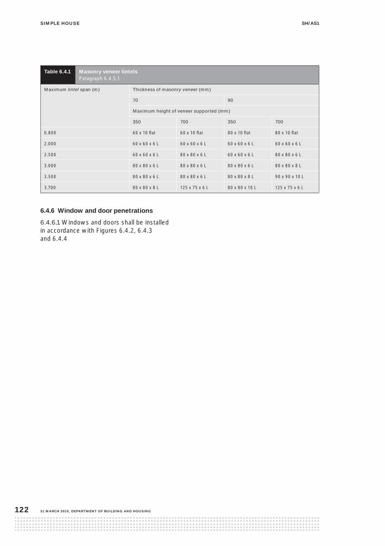
siMple house sh/as1
31 March 2010, DepartMent of BuilDing anD housing122
table 6.4.1 Masonry veneer lintels Paragraph 6.4.5.1
Maximum lintel span (m) Thickness of masonry veneer (mm)
70 90
Maximum height of veneer supported (mm)
350 700 350 700
0.800 60 x 10 flat 60 x 10 flat 80 x 10 flat 80 x 10 flat
2.000 60 x 60 x 6 L 60 x 60 x 6 L 60 x 60 x 6 L 60 x 60 x 6 L
2.500 60 x 60 x 6 L 80 x 80 x 6 L 60 x 60 x 6 L 80 x 80 x 6 L
3.000 80 x 80 x 6 L 80 x 80 x 6 L 80 x 80 x 6 L 80 x 80 x 8 L
3.500 80 x 80 x 6 L 80 x 80 x 6 L 80 x 80 x 8 L 90 x 90 x 10 L
3.700 80 x 80 x 8 L 125 x 75 x 6 L 80 x 80 x 10 L 125 x 75 x 6 L
6.4.6 Window and door penetrations
6.4.6.1 Windows and doors shall be installed in accordance with Figures 6.4.2, 6.4.3 and 6.4.4

siMple housesh/as1
DepartMent of BuilDing anD housing, 31 March 2010 123
figure 6.4.2 aluminium window to brick veneer – head and sill Paragraph 6.4.6.1

siMple house sh/as1
31 March 2010, DepartMent of BuilDing anD housing124
figure 6.4.3 aluminium window to brick veneer – jamb Paragraph 6.4.6.1

siMple housesh/as1
DepartMent of BuilDing anD housing, 31 March 2010 125
6.4.6.2 Aluminium door sills shall be installed in accordance with Figure 6.4.4
figure 6.4.4 aluminium door sill Paragraphs 6.4.6.1, 6.4.6.2 and 6.5.9.2

siMple house sh/as1
31 March 2010, DepartMent of BuilDing anD housing126
6.5.1 general
Refer to Paragraph 6.1 for general requirements for the installation of flat sheet (plywood and fibre-cement) wall claddings, including wall underlays, air seals, flashings, sill trays, ground clearances, etc.
6.5.2 Materials
6.5.2.1 Flat sheet wall claddings shall not be used as a bracing system and shall be limited to:
(a) plywood:
(i) in the grade, species and preservative treatment in accordance with Table 2.7
(ii) in a minimum of 5 ply, and
(iii) a minimum of 12 mm thickness,
(b) or to fibre-cement, minimum 7.5 mm thick, and complying with AS/NZS 2908: Part 2.
6.5.2.2 The grade, species and preservative treatment of cover battens, corner boards and exterior finishing timbers shall be in accordance with Table 2.7.
6.5.2.3 Flashings shall be selected in accordance with Paragraph 2.6.
6.5.2.4 Fixings shall be selected in accordance with Paragraph 2.5.
6.5.3 limitations
This Acceptable Solution is limited to plywood or fibre-cement installed with:
(a) the sheets running vertically
(b) all horizontal joints flashed, and
(c) all vertical joints battened.
contents
6.5.1 General
6.5.2 Materials
6.5.3 Limitations
6.5.4 Fixings
6.5.5 Joints
6.5.6 Cover battens and cover boards
6.5.7 Corners
6.5.8 Soffit details
6.5.9 Windows and doors
6.5.10 Finishes
figures
6.5.1 Vertical batten joint to plywood sheet
6.5.2 Vertical batten joint to fibre-cement
6.5.3 Horizontal joint to flat sheet claddings
6.5.4 External corner
6.5.5 Internal corner
6.5.6 Finish at gable soffit
6.5.7 Window installation to flat sheet claddings
6.5 flat sheet claddings

siMple housesh/as1
DepartMent of BuilDing anD housing, 31 March 2010 127
6.5.4 fixings
Flat sheets shall be fixed as follows, for:
(a) plywood sheet:
(i) 40 x 2.8 mm flat head nails at 150 mm centres to edges of sheet (min 7 mm from edge) and at 300 mm centres to body of sheet, and
(ii) 65 x 3.2 mm annular grooved nails at 300 mm centres in centre of cover batten
(b) fibre-cement sheet:
(i) 40 x 2.8 mm fibre-cement nails at 150 mm centres to edges of sheet (minimum 12 mm from edge) and at 300 mm centres to body of sheet, and
(ii) 65 x 3.15 mm jolt head nails at 300 mm centres in centre of cover batten.
6.5.5 Joints
Joints in sheets shall be made over solid support and shall incorporate:
(a) for vertical joints, a 2 mm expansion gap, see Figures 6.5.1 or 6.5.2, and
(b) for horizontal joints, a 10 mm expansion gap as per Figure 6.5.3.
Comment: Minimise the number of sheet joints to reduce the risk of leaking.
figure 6.5.2 Vertical batten joint to fibre-cement Paragraph 6.5.5
figure 6.5.3 horizontal joint to flat sheet claddingsParagraph 6.5.5
figure 6.5.1 Vertical batten joint to plywood sheet Paragraph 6.5.5

siMple house sh/as1
31 March 2010, DepartMent of BuilDing anD housing128
6.5.6 cover battens and cover boards
6.5.6.1 Cover battens
Timber cover battens shall be minimum ex 25 x 75 mm, and pre-primed. Sawn cover battens shall be installed with a dressed face against the cladding.
6.5.6.2 Corner boards
Timber corner boards shall be minimum ex 25 x 75 mm, and pre-primed.
6.5.7 corners
6.5.7.1 External corners
External corners shall be made using cover boards in accordance with Paragraph 6.5.6.2 and Figure 6.5.4.
6.5.7.2 Internal corners
Internal corners shall be made using corner battens or trim in accordance with Figure 6.5.5.
figure 6.5.4 external corner Paragraph 6.5.7.1
figure 6.5.5 internal corner Paragraph 6.5.7.2

siMple housesh/as1
DepartMent of BuilDing anD housing, 31 March 2010 129
6.5.8 soffit details
Soffits for flat sheet claddings shall be in accordance with Figure 6.5.6. Refer also to Paragraph 6.1.5.
Raking soffits shall have a corner flashing fixed behind soffit lining and over cladding in accordance with Figure 7.1.3.
figure 6.5.6 finish at gable soffit Paragraphs 6.1.5 and 6.5.8
6.5.9 Windows and doors
6.5.9.1 Windows and doors shall be installed in accordance with Figures 6.5.7 and 6.2.6.
6.5.9.2 Door sills shall be installed in accordance with Figure 6.4.4.
6.5.10 finishes
6.5.10.1 Both fibre-cement and plywood flat sheets shall be sealed on all edges prior to fixing.
6.5.10.2 Plywood shall be fully sealed on the back and finished as for timber weatherboards, in accordance with Paragraph 6.2.2.
6.5.10.3 Fibre-cement shall be fully sealed on the back and finished with a minimum two coat exterior acrylic paint system complying with AS 3730.
6.5.10.4 Cover battens, corner boards and exterior finishing timbers shall be finished as for timber weatherboards, in accordance with Paragraph 6.2.2.
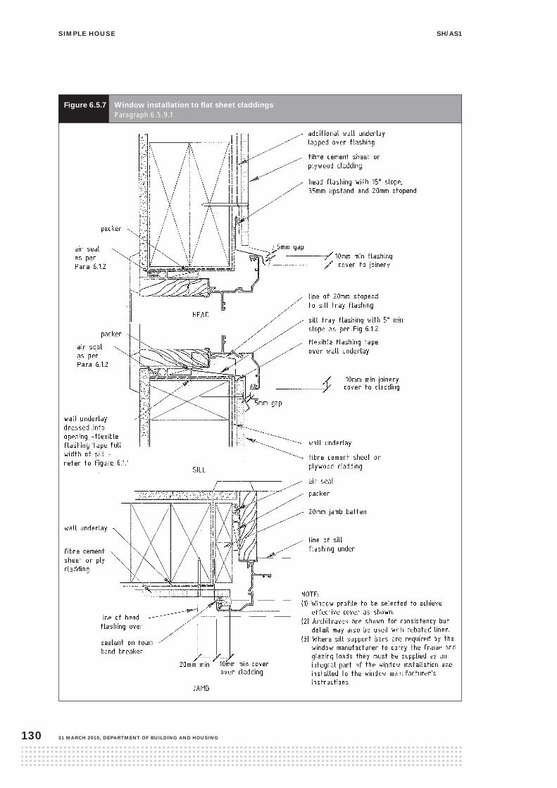
siMple house sh/as1
31 March 2010, DepartMent of BuilDing anD housing130
figure 6.5.7 Window installation to flat sheet claddings Paragraph 6.5.9.1

siMple housesh/as1
DepartMent of BuilDing anD housing, 31 March 2010 131
6.6.1 general
This section covers the horizontal and vertical junctions between the different wall claddings of this Acceptable Solution and how they shall be installed.
6.6.1.1 Refer to Paragraph 6.1 for general details and to the particular cladding:
(a) bevel-back weatherboard, Paragraph 6.2
(b) rusticated weatherboard, Paragraph 6.3
(c) masonry veneer, Paragraph 6.4
(d) flat sheet wall claddings, Paragraph 6.5, where a ‘flat sheet’ wall cladding may be either plywood or fibre cement.
6.6.1.2 For the wall cladding details to an attached garage with a steel lintel in accordance with Paragraph 4.5.1.5, refer to Paragraph 6.7.
6.6.1.3 Flashings shall be selected in accordance with Paragraph 2.6.
6.6.2 horizontal junctions – ‘Z-flashings’
For horizontal junctions between flat sheet wall claddings, the junction shall be installed in accordance with Figure 6.5.3.
contents
6.6.1 General
6.6.2 Horizontal junctions – ‘Z-flashings’
6.6.3 Horizontal junctions – masonry veneer
6.6.4 Vertical cladding junctions
figures
6.6.1 Horizontal junction – weatherboard or flat sheet over masonry veneer (sill brick)
6.6.2 Horizontal junction – weatherboard or flat sheet over masonry veneer (metal sill capping alternative)
6.6.3 Vertical junction – rusticated weatherboard to flat sheet
6.6.4 Vertical junction – bevel-back weatherboard to flat sheet
6.6.5 Vertical junction – weatherboard to masonry veneer
6.6.6 Vertical junction – flat sheet to masonry veneer
6.6 claddings junctions

siMple house sh/as1
31 March 2010, DepartMent of BuilDing anD housing132
6.6.3 horizontal junctions – masonry veneer
Where weatherboard or flat sheet wall cladding is used above masonry veneer, the junction shall be installed in accordance with Figures 6.6.1 or 6.6.2.
figure 6.6.1 horizontal junction – weatherboard or flat sheet over masonry veneer (sill brick) Paragraph 6.6.3

siMple housesh/as1
DepartMent of BuilDing anD housing, 31 March 2010 133
figure 6.6.2 horizontal junction – weatherboard or flat sheet over masonry veneer (metal sill capping option) Paragraph 6.6.3
6.6.4 Vertical cladding junctions
6.6.4.1 Vertical junctions between the different claddings shall be installed as described in this Acceptable Solution.
6.6.4.2 Refer to Paragraph 6.1 for general details and for the particular vertical wall cladding junction:
(a) rusticated weatherboard to flat sheet, refer to Figure 6.6.3
(b) bevel-back weatherboard to flat sheet, refer to Figure 6.6.4
(c) weatherboard to masonry veneer, refer to Figure 6.6.5
(d) flat sheet to masonry veneer, refer to Figure 6.6.6.

siMple house sh/as1
31 March 2010, DepartMent of BuilDing anD housing134
figure 6.6.3 Vertical junction – rusticated weatherboard to flat sheet Paragraph 6.6.4

siMple housesh/as1
DepartMent of BuilDing anD housing, 31 March 2010 135
figure 6.6.4 Vertical junction – bevel-back weatherboard to flat sheet Paragraph 6.6.4

siMple house sh/as1
31 March 2010, DepartMent of BuilDing anD housing136
figure 6.6.5 Vertical junction – weatherboard to masonry veneer Paragraph 6.6.4
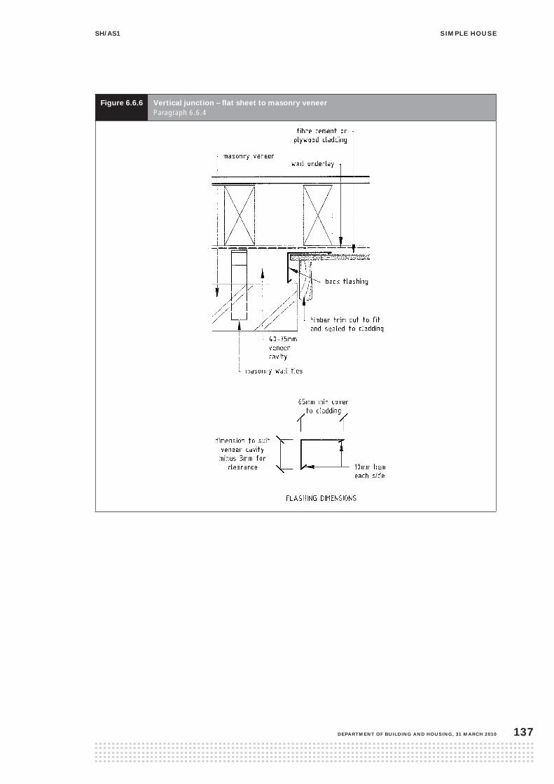
siMple housesh/as1
DepartMent of BuilDing anD housing, 31 March 2010 137
figure 6.6.6 Vertical junction – flat sheet to masonry veneer Paragraph 6.6.4

siMple house sh/as1
31 March 2010, DepartMent of BuilDing anD housing138
6.7.1 general
This section covers the wall cladding details for an attached garage, including those for where a steel lintel is used in accordance with Paragraph 4.5.1.5.
6.7.2 A garage that requires a roof-to-wall apron, parallel or transverse flashing is outside the scope of this Acceptable Solution for simple houses.
CommentRoof elements finishing within the boundaries formed by exterior walls pose a high risk of weathertightness failure.
6.7.3 Refer to Paragraph 6.1 for general requirements for the installation of wall claddings, including wall underlays, air seals, flashings, ground clearances, etc.
6.7.4 For the details of a particular wall cladding in this Acceptable Solution, refer to:
(a) garage head for masonry veneer, Figure 6.7.1
(b) garage jamb for masonry veneer, Figure 6.7.2
(c) garage head for flat sheet wall claddings or weatherboards, Figure 6.7.3
(d) garage jamb for flat sheet wall claddings Figure 6.7.4
(e) garage jamb for weatherboards, Figure 6.7.5.
6.7.5 The grade, species and preservative treatment of cover boards or exterior finishing timbers shall be in accordance with Table 2.7.
The grade, species and preservative treatment of the timber jambs to any exterior joinery in an attached garage shall be in accordance with Table 2.7.
6.7.6 Flashings shall be selected in accordance with Paragraph 2.6.
contents
6.7.1 General
figures
6.7.1 Garage head for masonry veneer with steel lintel
6.7.2 Garage jamb for masonry veneer with steel
6.7.3 Garage head for flat sheet claddings or weatherboard (with steel lintel)
6.7.4 Garage jamb for flat sheet claddings (with steel lintel)
6.7.5 Garage jamb for weatherboards (with steel lintel)
6.7 attached garage – cladding details

siMple housesh/as1
DepartMent of BuilDing anD housing, 31 March 2010 139
figure 6.7.1 garage head for masonry veneer with steel lintel Paragraph 6.7.4

siMple house sh/as1
31 March 2010, DepartMent of BuilDing anD housing140
figure 6.7.2 garage jamb for masonry veneer with steel lintel Paragraph 6.7.4

siMple housesh/as1
DepartMent of BuilDing anD housing, 31 March 2010 141
figure 6.7.3 garage head for flat sheet claddings or weatherboard (with steel lintel) Paragraph 6.7.4

siMple house sh/as1
31 March 2010, DepartMent of BuilDing anD housing142
figure 6.7.4 garage jamb for flat sheet claddings (with steel lintel) Paragraph 6.7.4

siMple housesh/as1
DepartMent of BuilDing anD housing, 31 March 2010 143
figure 6.7.5 garage jamb for weatherboards (with steel lintel) Paragraph 6.7.4

siMple house sh/as1
31 March 2010, DepartMent of BuilDing anD housing144
7.1.1 pitch
Roof pitch shall comply with Paragraph 1.2 (j), or as modified below:
(a) for pressed metal tiles – refer to Paragraph 7.3.2
(b) for masonry tiles – refer to Paragraph 7.4.2.
7.1.2 penetrations
7.1.2.1 Roof penetrations shall not interrupt roof framing.
7.1.3 flashings
7.1.3.1 Flashing material shall be in accordance with Paragraph 2.6.
7.1.3.2 The roofing shall be flashed at the roof edges. In Very High wind zones (refer to Paragraph 2.2), the discharge to a gutter shall be flashed in accordance with Paragraph 7.1.4.1. All exposed flashings, such as barge and ridge flashings, are to be fixed along both edges.
7.1.3.3 Flashing joints
Metal flashings shall be joined using a neutral cure silicone sealant in conjunction with mechanical fasteners, where required in accordance with Figure 7.1.1.
figure 7.1.1 flashing joints Paragraphs 6.1.4, 7.1.3.3 and 7.2.4.3
contents
7.1.1 Pitch
7.1.2 Penetrations
7.1.3 Flashings
7.1.4 Eaves
7.1.5 Roof underlay
7.1.6 Gutters and downpipes
7.1.6 Valley gutters
figures
7.1.1 Flashing joints
7.1.2 Eaves design
7.1.3 Raking eaves flashings
tables
7.1.1 Downpipe size for given roof pitch and area
7.0 roofing
7.1 general

siMple housesh/as1
DepartMent of BuilDing anD housing, 31 March 2010 145
figure 7.1.3 raking eaves flashingsParagraphs 6.1.5.2 and 7.1.4
7.1.4 eaves
7.1.4.1 Eaves flashings into gutter
Eaves shall be closed in and in accordance with either Figure 7.1.2 or 7.1.3.
7.1.4.2 Raking eaves flashings
Flashings to all upward raking eaves shall be installed in accordance with Figure 7.1.3.
figure 7.1.2 eaves design Paragraphs 6.1.5.2 and 7.1.4

siMple house sh/as1
31 March 2010, DepartMent of BuilDing anD housing146
7.1.5 roof underlay
7.1.5.1 General
All roofing, except masonry tiles roofs in accordance with Table 7.4.1, shall have an absorbent, paper-based roof underlay that complies with NZS 2295.
7.1.5.2 Installation
Roof underlay shall be laid with minimum 150 mm laps, and either across the roof slope or down it. When laid across the slope, the upper sheet shall lap over the lower sheet.
7.1.5.3 Underlay support
Roof underlays shall be supported on 0.9 mm galvanised wire mesh, unless it is self-supporting in which case it shall span no more than 1.2 m in any one direction.
7.1.6 gutters and downpipes
7.1.6.1 There shall be no internal downpipes or internal gutters.
7.1.6.2 Materials
Gutters and downpipes shall be:
(a) AZ150 Aluminium-zinc coated steel to AS 1397 factory coated to AS/NZS 2728, or
(b) ZM275 or Z450 Zinc coated steel factory coated to AS/NZS 2728, or
(c) uPVC.
7.1.6.3 Eaves gutters shall have a minimum of 5,000 mm2 cross-sectional area or sized in accordance with the Acceptable Solution E1/AS1 for Building Code Clause E1 Surface Moisture, and designed to overflow to the exterior of the building.
7.1.6.4 Downpipes shall be installed to serve the roof areas, as in Table 7.1.1. Shapes other than round are acceptable only with a minimum dimension of 50 mm and equivalent cross-sectional area.
table 7.1.1 Downpipe size for given roof area Paragraph 7.1.6.4
Downpipe minimum
internal size (mm)
Cross-
sectional
area (mm2)
Plan area
of roof
served (m²)
63 mm diameter 3110 50
74 mm diameter 4300 70
100 mm diameter 7850 130
7.1.7 Valley gutters
Valley gutters shall be constructed as shown for the applicable roof cladding (refer to Figures 7.2.5, 7.3.4 or 7.4.4) and be continuously supported with gutter boards of the grade, species and treatment in accordance with Table 2.7, and:
(a) have a minimum width of 250 mm
(b) serve a catchment area feeding into the valley gutter of no more than 25 m2 plan area
(c) if metal, be separated from any treated timber by roof underlay
(d) have no fixings in the gutter bottom or sides
(e) be fixed at the upper end only, and be secured with a purpose-made clip system for the remaining length
(f) have all joints lapped and sealed in accordance with Paragraph 7.1.3.3
(g) discharge to the eaves gutter
(h) receive no direct discharge from downpipes or spreaders
(i) not change direction in plan.

siMple housesh/as1
DepartMent of BuilDing anD housing, 31 March 2010 147
7.2.1 profiles
Profiles shall be in accordance with Figure 7.2.1:
(a) corrugated – curved with a crest height of 17 mm minimum, or
(b) trapezoidal – symmetrical or asymmetrical, with a crest height between 27 and 32 mm and crest-to-crest spacing of 190 mm maximum.
figure 7.2.1 low-profile roofing profiles Paragraph 7.2.1
7.2.2 Materials
7.2.2.1 Base metal thickness
Profiled metal roofing shall be made from steel with a minimum BMT of 0.4 mm in Grade G550, or Grade G300 for 0.55 BMT steel.
7.2.2.2 Protective coating
Steel shall have a minimum protective metal coating of:
(a) AZ150 Aluminium-zinc to AS 1397 with a factory-applied finish in accordance with AS/NZS 2728 Type 4, and in sea spray zone and corrosion zone 1 the factory-applied finish shall be Type 5 minimum
(b) Z450 steel zinc coated, unpainted, or ZM275 factory coated to AS/NZS 2728 Type 5 or better.
contents
7.2.1 Profiles
7.2.2 Materials
7.2.3 Fixings
7.2.4 Flashings
figures
7.2.1 Low-profile roofing profiles
7.2.2 Pipe penetrations up to 80 mm diameter
7.2.3 Pipe penetrations up to 500 mm diameter
7.2.4 Barge flashings
7.2.5 Valley gutter
tables
7.2.1 Profiled metal roofing maximum spans
7.2.2 Fixings to profiled metal roofing
7.2 profiled metal roofs
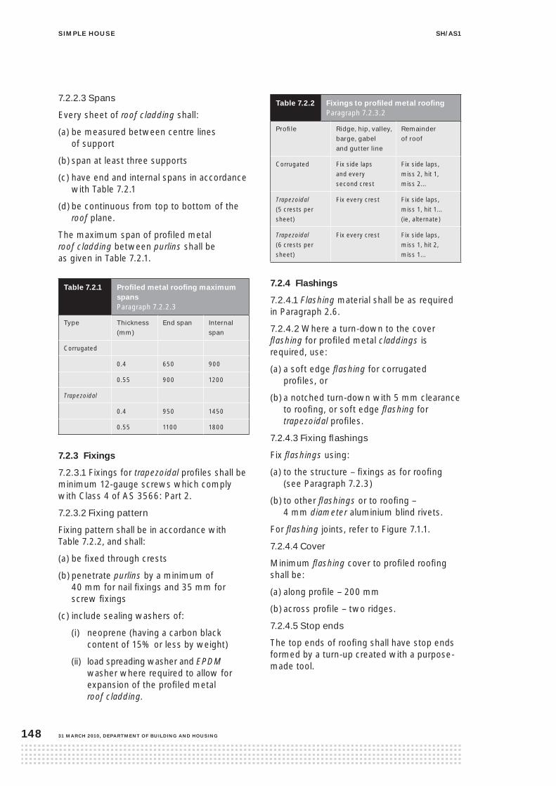
siMple house sh/as1
31 March 2010, DepartMent of BuilDing anD housing148
7.2.2.3 Spans
Every sheet of roof cladding shall:
(a) be measured between centre lines of support
(b) span at least three supports
(c) have end and internal spans in accordance with Table 7.2.1
(d) be continuous from top to bottom of the roof plane.
The maximum span of profiled metal roof cladding between purlins shall be as given in Table 7.2.1.
table 7.2.1 profiled metal roofing maximum spans Paragraph 7.2.2.3
Type Thickness
(mm)
End span Internal
span
Corrugated
0.4 650 900
0.55 900 1200
Trapezoidal
0.4 950 1450
0.55 1100 1800
7.2.3 fixings
7.2.3.1 Fixings for trapezoidal profiles shall be minimum 12-gauge screws which comply with Class 4 of AS 3566: Part 2.
7.2.3.2 Fixing pattern
Fixing pattern shall be in accordance with Table 7.2.2, and shall:
(a) be fixed through crests
(b) penetrate purlins by a minimum of 40 mm for nail fixings and 35 mm for screw fixings
(c) include sealing washers of:
(i) neoprene (having a carbon black content of 15% or less by weight)
(ii) load spreading washer and EPDM washer where required to allow for expansion of the profiled metal roof cladding.
table 7.2.2 fixings to profiled metal roofingParagraph 7.2.3.2
Profile Ridge, hip, valley,
barge, gabel
and gutter line
Remainder
of roof
Corrugated Fix side laps and every second crest
Fix side laps, miss 2, hit 1, miss 2...
Trapezoidal (5 crests per sheet)
Fix every crest Fix side laps, miss 1, hit 1... (ie, alternate)
Trapezoidal (6 crests per sheet)
Fix every crest Fix side laps, miss 1, hit 2, miss 1...
7.2.4 flashings
7.2.4.1 Flashing material shall be as required in Paragraph 2.6.
7.2.4.2 Where a turn-down to the cover flashing for profiled metal claddings is required, use:
(a) a soft edge flashing for corrugated profiles, or
(b) a notched turn-down with 5 mm clearance to roofing, or soft edge flashing for trapezoidal profiles.
7.2.4.3 Fixing flashings
Fix flashings using:
(a) to the structure – fixings as for roofing (see Paragraph 7.2.3)
(b) to other flashings or to roofing – 4 mm diameter aluminium blind rivets.
For flashing joints, refer to Figure 7.1.1.
7.2.4.4 Cover
Minimum flashing cover to profiled roofing shall be:
(a) along profile – 200 mm
(b) across profile – two ridges.
7.2.4.5 Stop ends
The top ends of roofing shall have stop ends formed by a turn-up created with a purpose- made tool.

siMple housesh/as1
DepartMent of BuilDing anD housing, 31 March 2010 149
figure 7.2.3 pipe penetrations up to 500 mm diameter Paragraphs 7.2.4.7 and 7.3.5
7.2.4.8 Ridge flashing
A purpose-made ridge flashing with soft edge or profiled turn-downs providing a minimum 200 mm cover to roofing shall be fitted to ridges and hips.
7.2.4.6 Turn-down and discharge
At the bottom end of roofing where the roof discharges to a gutter, the end of the roofing shall:
(a) be turned down to form a drip-edge, and
(b) extend 50 mm past the fascia to discharge into the gutter.
7.2.4.7 Penetrations
Roof penetrations shall be flashed using an EPDM boot flashing:
(a) up to 80 mm diameter in accordance with Figure 7.2.2
(b) up to 500 mm diameter in accordance with Figure 7.2.3.
figure 7.2.2 pipe penetrations up to 80 mm diameter Paragraphs 7.2.4.7 and 7.3.5
7.2.4.9 Barge flashings
Barge flashings shall be dimensioned in accordance with Figure 7.2.4.

siMple house sh/as1
31 March 2010, DepartMent of BuilDing anD housing150
figure 7.2.4 Barge flashings Paragraph 7.2.4.9
7.2.4.10 Valley gutters
Valley gutters shall be in accordance with Paragraph 7.1.7 and dimensioned to Figure 7.2.5.
figure 7.2.5 Valley gutter Paragraphs 7.1.7 and 7.2.4.10

siMple housesh/as1
DepartMent of BuilDing anD housing, 31 March 2010 151
7.3.1 Materials
Metal tiles shall be manufactured with a steel base metal to meet the requirements of NZS 4217 and shall:
(a) have a minimum BMT of 0.39 mm
(b) be grade G300
(c) have applied protective metallic coating of:
(i) aluminium-zinc AZ 150 to AS 1397, or
(ii) zinc ZM275 to AS 1397, and
(d) have a factory-applied finish complying with AS/NZS 2728 Type 4 minimum.
CommentAdditional protective and decorative coatings such as factory-painted or bonded resin and chip finish and a clear over coating may be applied.
7.3.2 pitch
The minimum roof pitches for metal tiles shall be:
(a) 12° for profiles resembling traditional profiles, or
(b) 15° for profiles resembling shake profiles.
7.3.3 profiles
Pressed metal tile profiles shall be in accordance with Figure 7.3.1.
figure 7.3.1 profiles for pressed metal tilesParagraph 7.3.3
contents
7.3.1 Materials
7.3.2 Pitch
7.3.3 Profiles
7.3.4 Fixings
7.3.5 Penetrations
7.3.6 Flashings
figures
7.3.1 Profiles for pressed metal tiles
7.3.2 Fixings to pressed metal tiles
7.3.3 Eaves finish and barge flashing
7.3.4 Valley gutters
7.3 pressed metal tiles

siMple house sh/as1
31 March 2010, DepartMent of BuilDing anD housing152
7.3.4 fixings
Pressed metal tiles shall be fixed in accordance with Figure 7.3.2, with:
(a) 50 x 2.8 mm hot-dipped galvanised painted flat-head annular-grooved nails (or Type 304 stainless steel for sea spray zone or corrosion zone 1). For fixings through the top of the tiles, use neoprene washers containing no more than 15% by weight carbon black content, and with
(b) four fixings per sheet through:
(i) the turn-down of the tiles for the body of the roof, and
(ii) the top of the profile slope for sheets at the eaves, avoiding the weather channel of the tiles.
figure 7.3.2 fixings to pressed metal tilesParagraph 7.3.4
7.3.5 penetrations
Penetrations for pipes shall be limited to 500 mm in diameter and shall be flashed using EPDM or silicone rubber boot flashings in accordance with Figures 7.2.2 and 7.2.3.

siMple housesh/as1
DepartMent of BuilDing anD housing, 31 March 2010 153
7.3.6 flashings
7.3.6.1 General
Flashings shall be purpose-made using the same material as the roofing being flashed.
7.3.6.2 Eaves and barge
Eaves and barges shall be in accordance with Figure 7.3.3. Refer also to Paragraph 7.1.4.
figure 7.3.3 eaves finish and barge flashingParagraphs 6.1.5 and 7.3.6.2

siMple house sh/as1
31 March 2010, DepartMent of BuilDing anD housing154
7.3.6.3 Valley gutters
Valley gutters shall be to the dimensions given in Figure 7.3.4.
figure 7.3.4 Valley gutters Paragraphs 7.1.1 and 7.3.6.3

siMple housesh/as1
DepartMent of BuilDing anD housing, 31 March 2010 155
7.4.1 Materials
7.4.1.1 Masonry tiles shall have a mass not exceeding 60 kg/m2, and:
(a) concrete tiles shall meet the requirements of NZS 4206
(b) clay tiles shall meet the requirements of AS 2049.
7.4.1.2 Tile profiles
For the purposes of this Paragraph 7.4, tiles shall be divided into three types:
(a) Type I: double profile tiles having two distinct watercourses and with a minimum watercourse depth of 18 mm
(b) Type II: single profile tiles having one watercourse, with a minimum of 25 mm in height, or
(c) Type III: tiles not fitting the Type I and Type II categories, and including flat tiles and those resembling slates, shakes and shingles.
7.4.2 installation
7.4.2.1 Masonry tile roof cladding shall be installed in accordance with NZS 4206 onto battens, except the minimum pitch and roof underlay where required shall be in accordance with Table 7.4.1.
table 7.4.1 Minimum pitches for masonry tiles Paragraphs 7.1.5.1, 7.4.1 and 7.4.2
Tile Material Profile type With underlay Without underlay
Concrete tiles Type I 15° 20°
Type II 20° Not allowed
Type III 25° Not allowed
Clay tiles Type I 20° 25°
Type II 20° Not allowed
Type III 25° Not allowed
contents
7.4.1 Materials
7.4.2 Installation
7.4.3 Flashings and fixings
7.4.4 Anti-ponding boards
7.4.5 Details and flashings
figures
7.4.1 Masonry tile – ridge
7.4.2 Masonry tile – barge
7.4.3 Masonry tile – eaves
7.4.4 Masonry tile – valley gutter
7.5.5 Masonry tile – pipe penetration
tables
7.4.1 Minimum pitches for masonry tiles
7.4 Masonry tiles

siMple house sh/as1
31 March 2010, DepartMent of BuilDing anD housing156
7.4.3 flashings and fixings
Materials for flashings, gutters and fixings shall be in accordance with Paragraphs 2.6 and 7.1.3 and be compatible with mortar and bedding.
7.4.4 anti-ponding boards
Anti-ponding boards shall be installed where a roofing underlay is required (refer to Figure 7.4.3). Where anti-ponding boards are used, these shall be set to a minimum fall of 5°, and shall be 9 mm plywood of the grade, species and treatment in accordance with Table 2.7.
7.4.5 Details and flashings
Hips, ridges, valleys and barges shall be made weathertight by installing flashings and seals in accordance with Figures 7.4.1 to 7.4.5.
figure 7.4.1 Masonry tile – ridge Paragraph 7.4.5
figure 7.4.2 Masonry tile – barge Paragraph 7.4.5

siMple housesh/as1
DepartMent of BuilDing anD housing, 31 March 2010 157
figure 7.4.3 Masonry tile – eaves Paragraphs 7.4.4 and 7.4.5
figure 7.4.4 Masonry tile – valley gutter Paragraphs 7.1.1 and 7.4.5

siMple house sh/as1
31 March 2010, DepartMent of BuilDing anD housing158
7.4.6 penetrations
Penetrations for pipes shall be limited to 500 mm in diameter and shall be flashed using EPDM or silicone rubber boot flashings in accordance with Figure 7.4.5.
figure 7.4.5 Masonry tile – pipe penetration Paragraphs 7.4.5 and 7.4.6

siMple housesh/as1
DepartMent of BuilDing anD housing, 31 March 2010 159
8.1 electrical 8.0 services
8.1.1 All electrical installations shall:
(a) comply with AS/NZS 3000, (known as the Australian/New Zealand Wiring Rules)
(b) be installed by a registered electrician.
8.1.2 An energy work certificate shall be supplied to the BCA and/or owner by the electrician at completion of all electrical work.
8.1.3 Power outlet sockets and light switches shall be fitted between 500 mm and 1.2 m from finished floor level (1.0 m recommended for all light switches) and a minimum of 500 mm from any corner.
8.1.4 Isolating switches to ovens and hob units shall not be mounted directly above the appliance.
contents
8.1 electrical
8.2 gas
8.3 Water supply
8.3.1 Scope
8.3.2 Installation
8.3.3 Connection
8.4 hot water
8.4.1 Scope
8.4.2 Hot water heaters
8.4.3 Hot water temperatures
8.4.4 Water supply
8.5 surface water
8.5.1 Scope
8.5.2 Installation
8.5.3 Connection to outfall
8.6 sanitary plumbing and drainage
8.6.1 Scope
8.6.2 Materials
8.6.3 Water traps
8.6.4 Fixture discharge pipes
8.6.5 Gully traps
8.6.6 Floor waste gully
8.6.7 Fixture discharge pipes serving soil fixtures
8.6.8 Connection to drains
figures
8.1 Waste pipes discharging to a gully trap
8.2 Connection of wastes to a floor waste gully
8.3 Soil fixture discharge pipes
tables
8.1 Fixture discharge pipe sizes

siMple house sh/as1
31 March 2010, DepartMent of BuilDing anD housing160
8.2 gas 8.3 Water supply
8.2.1 The design and installation of a gas system shall:
(a) comply with NZS 5261, and
(b) be installed by a person authorised under the Plumbers, Gasfitters and Drainlayers Act.
8.3.1 scope
A cold water supply shall be installed and reticulated to:
(a) sinks
(b) tubs
(c) basins
(d) showers
(e) baths
(f) hot water heaters
(g) exterior hose taps
(h) other sanitary fixtures or appliances as required by the owner.
8.3.2 installation
All pipework and fittings for the reticulation of water shall:
(a) comply with AS/NZS 3500.5 Section 2, and
(b) be installed by a person authorised under the Plumbers, Gasfitters and Drainlayers Act.
8.3.3 connection
The house shall be connected to a water supply that complies with:
(a) Drinking Water Standards for New Zealand 2005, Ministry of Health, or
(b) Household Water Supplies: the selection, operation and maintenance of individual household water supplies, Ministry of Health (revised April 2006).

siMple housesh/as1
DepartMent of BuilDing anD housing, 31 March 2010 161
8.4 hot water
8.4.1 scope
A hot water supply shall be installed and reticulated to:
(a) kitchen sinks
(b) laundry tubs
(c) basins
(d) showers
(e) baths
(f) other sanitary fixtures and appliances as required by the owner.
8.4.2 hot water heaters
Hot water heaters shall be installed in accordance with AS/NZS 3500.5 Section 3, and may be:
(a) electric mains or low pressure storage water heater complying with NZS 4606, or
(b) gas mains or low pressure storage water heater complying with NZS 5262 and NZS 4606, or
(c) gas instantaneous water heater complying with NZS 5262 or electric instantaneous water heater complying with AS/NZS 3350.2, or
(d) integrated heat pump storage water heater complying with AS/NZS 2712, or
(e) solar water heater complying with AS/NZS 2712.
8.4.3 hot water temperatures
8.4.3.1 To prevent the growth of Legionella bacteria:
(a) storage water heaters shall have a thermostat set to store the water at a temperature of no less than 60°C, and
(b) solar hot water systems shall comply with G12/AS2 Paragraph 3.5.
8.4.3.2 The maximum water temperature delivered from the outlets of showers, baths, basins and other personal hygiene fixtures shall not exceed 55° C.
8.4.3.3 Installing a tempering valve complying with AS 1357.2 between the water heater and the outlet of personal hygiene outlets is an acceptable method of limiting the water temperature to not exceed 55° C.
8.4.4 Water supply
The water heater shall be supplied from the cold water supply.

siMple house sh/as1
31 March 2010, DepartMent of BuilDing anD housing162
8.5 surface water 8.6 sanitary plumbing and drainage
8.5.1 scope
This Acceptable Solution provides for the collection of surface water by means of the gutters and downpipes and disposal by means of a drain to an outfall.
8.5.2 installation
The simple house rainwater collection systems of gutters and downpipes shall comply with Paragraph 7.1.6 of this Acceptable Solution.
8.5.3 connection to outfall
The simple house shall be connected to a piped surface water system complying with the provisions of Acceptable Solution E1/AS1. Where the outfall is owned by a network utility operator, the connection shall be in a manner acceptable to it.
8.6.1 scope
This paragraph for sanitary plumbing and drainage covers the reticulation of foul water from all sanitary fixtures and appliances to a gully trap or drain and the site reticulation drainage system for foul water discharging to an outfall. Installations shall comply with this Acceptable Solution, or shall be in accordance with AS/NZS 3500.5 Section 4.
8.6.2 Materials
Materials for sanitary plumbing pipes, traps, valves and fittings shall be:
(a) air admittance valves in accordance with AS/NZS 4936
(b) PVC pipe and fittings in accordance with AS/NZS 1260.
8.6.3 Water traps
8.6.3.1 Discharges from sanitary fixtures and sanitary appliances shall have a water trap to prevent foul air from the plumbing system entering the simple house.
8.6.3.2 Water traps shall be:
(a) removable
(b) able to be dismantled.
8.6.3.3 Under normal operating conditions, water traps shall retain a water seal depth of not less than 65 mm, plus or minus 10 mm.
8.6.3.4 The diameter of a water trap and the discharge pipe shall be not less than that given in Table 8.1.
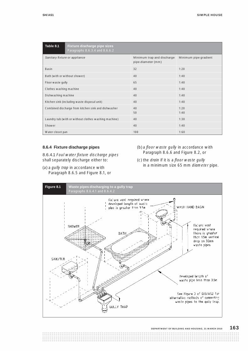
siMple housesh/as1
DepartMent of BuilDing anD housing, 31 March 2010 163
table 8.1 fixture discharge pipe sizes Paragraphs 8.6.3.4 and 8.6.6.2
Sanitary fixture or appliance Minimum trap and discharge
pipe diameter (mm)
Minimum pipe gradient
Basin 32 1:20
Bath (with or without shower) 40 1:40
Floor waste gully 65 1:40
Clothes washing machine 40 1:40
Dishwashing machine 40 1:40
Kitchen sink (including waste disposal unit) 40 1:40
Combined discharge from kitchen sink and dishwasher 40 50
1:20 1:40
Laundry tub (with or without clothes washing machine) 40 1:30
Shower 40 1:40
Water closet pan 100 1:60
8.6.4 fixture discharge pipes
8.6.4.1 Foul water fixture discharge pipes shall separately discharge either to:
(a) a gully trap in accordance with Paragraph 8.6.5 and Figure 8.1, or
(b) a floor waste gully in accordance with Paragraph 8.6.6 and Figure 8.2, or
(c) the drain if it is a floor waste gully in a minimum size 65 mm diameter pipe.
figure 8.1 Waste pipes discharging to a gully trap Paragraphs 8.6.4.1 and 8.6.4.2

siMple house sh/as1
31 March 2010, DepartMent of BuilDing anD housing164
8.6.4.2 Foul water discharge pipes shall be vented by a fixture vent or air admittance valve:
(a) where their length is more than 3.5 m, or
(b) where the height from the fixture trap water seal to the gully trap water seal is 1.5 m or greater, with 32 mm diameter waste pipes.
8.6.5 gully traps
8.6.5.1 All gully traps shall be constructed and installed to prevent the ingress of surface water and foreign bodies likely to cause a blockage, shall be located within the legal boundary of the land on which the simple house is erected, and shall have:
(a) the overflow level of the gully dish no less than:
(i) 25 mm above paved surfaces, or
(ii) 100 mm above unpaved surfaces
(b) a grating that will allow surcharge
(c) a minimum outlet pipe diameter of 100 mm
(d) a water seal depth of at least 65 mm
(e) at least one discharge pipe discharging to the gully trap to avoid water seal evaporation
(f) waste pipes that discharge to the gully trap arranged to permit easy cleaning of the gully trap
(g) waste pipe outlets located at least 20 mm above water seal level and at least 20 mm below the grating
(h) the top of the water seal no more than 600 mm below the top of the gully dish
(i) adequate support from bedding and backfilling with concrete no less than 75 mm thick surrounding the entire gully dish and which is separated from the simple house foundation
(j) a minimum of 600 mm clear access space above the gully dish.
8.6.5.2 In order to provide overflow relief for the drainage system, there shall be at least one gully trap which shall be:
(a) positioned so that the top of the gully dish is no less than 150 mm below the overflow level of the lowest sanitary appliance or fixture served by the drainage system
(b) located in a visible position
(c) installed so that surcharge cannot enter into or under buildings.
8.6.6 floor waste gully
8.6.6.1 For the purposes of this Acceptable Solution, floor waste gullies shall be deemed to be a fixture trap.
8.6.6.2 Connection of fixtures
The following fixtures, contained within the same room, may discharge to a floor waste gully:
(a) basin
(b) bath, shower/bath
(c) shower.
Waste pipes connecting to a floor waste gully shall be sized in accordance with Table 8.1.
8.6.6.3 Waste pipes discharging to a floor waste gully
Each fixture shall be connected to a floor waste gully by an individual waste pipe connected to the gully riser, as shown in Figure 8.2, by either:
(a) a trapped waste pipe falling at a grade of not less than 2.5% (1 in 40) and with a maximum developed length of 2.5 m, or
(b) an un-trapped waste pipe falling at a grade of not less than 2.5% (1 in 40) and with a maximum developed length of 1.2 m.
The discharge pipe from a floor waste gully shall connect to a drain or discharge to a gully trap.

siMple housesh/as1
DepartMent of BuilDing anD housing, 31 March 2010 165
figure 8.2 connection of wastes to a floor waste gully Paragraphs 8.6.4.1 and 8.6.6.3
8.6.6.4 Removable grate
Floor waste gullies shall be installed with a removable grate to which there is ready access, and a riser of 80 mm minimum diameter at floor surface level. Shower outlets may be connected to a floor waste gully.
8.6.6.5 Height of gully riser
The minimum height of the floor waste gully, measured from the top of the water seal to the floor level, shall be 150 mm.
8.6.7 fixture discharge pipes serving soil fixtures
Fixture discharge pipes serving soil fixtures shall discharge directly to the drain in accordance with Figure 8.3.

siMple house sh/as1
31 March 2010, DepartMent of BuilDing anD housing166
figure 8.3 soil fixture discharge pipes Paragraph 8.6.7

siMple housesh/as1
DepartMent of BuilDing anD housing, 31 March 2010 167
8.6.8 connection to drains
Gully traps and soil fixture discharge pipes shall be connected to the drain. The drain shall be laid in accordance with either Acceptable Solution G13/AS2 or with AS/NZS 3500.5 Section 4. Drains shall:
(a) have a drain vent pipe located so that the length of a drain upstream of the drain vent connection is less than 10 m with a minimum diameter of 80 mm and terminated to the requirements of Paragraph 5.7.3 of G13/AS1 Sanitary Plumbing
(b) be connected to the network utility operator sewer and in accordance with their requirements, or
(c) be connected to an on-site disposal designed in accordance with AS/NZS 1547 Part 4.

siMple house sh/as1
31 March 2010, DepartMent of BuilDing anD housing168
9.1 Wet areas 9.0 facilities
Wet areas shall include bathrooms and showers, laundries, sanitary compartments and kitchens areas.
9.1.1 floor finish
Floor finishes to wet areas shall be impervious and easily cleaned. Wet area floor finishes shall be limited to:
(a) sheet vinyl with welded joints
(b) timber or cork, with a three coat polyurethane finish, on a waterproof membrane
(c) polished and sealed concrete, or
(d) ceramic or porcelain tiles having a 6% maximum water absorption, laid on a waterproof membrane on a concrete floor, and finished with a non-porous grout. They shall be installed so that the substrate, waterproof membrane, adhesive, grout and tiles are all compatible with each other.
For floor finishes to showers, refer to Paragraphs 9.2.2.2, or 9.2.3.1.
9.1.2 Wall finish
Wall finishes to wet areas shall be impervious and easily cleaned. Wet area wall finishes shall be limited to:
(a) washable gloss or semi-gloss paint surface
(b) pre-finished sheet linings, or
(c) ceramic or porcelain tiles having 6% maximum water absorption and finished with a non-porous grout. They shall be installed so that the sealed substrate, adhesive, grout and tiles are all compatible with each other.
For wall finishes to showers, refer to Paragraphs 9.2.2.3 or 9.2.3.2 and for showers over baths, refer to Paragraph 9.2.4.
9.1.3 Junctions to floors, walls and fixtures
Joints between floors, walls and fixtures shall be sealed with flexible sealant, to prevent water penetration to concealed spaces or behind linings.
contents
9.1 Wet areas
9.1.1 Floor finish
9.1.2 Wall finish
9.2 personal hygiene
9.2.1 Bathrooms
9.2.2 Showers
9.3 cooking and food preparation
9.4 laundries
9.5 Ventilation
9.6 fire
9.6.1 Boundary separation
9.6.2 Smoke alarms
9.7 natural light
9.8 artificial lighting
9.9 heating
9.10 access
9.10.1 Slip resistance
9.10.2 Accessibility
9.10.3 Level entry
figures
9.1 Finish of linings to shower tray
9.2 Finish to bath
9.3 Impervious floor and wall linings about shower head
9.4 Level threshold at ground level

siMple housesh/as1
DepartMent of BuilDing anD housing, 31 March 2010 169
9.2 personal hygiene
9.2.1 Bathrooms
9.2.1.1 Houses shall contain at least one each of the following sanitary fixtures:
(a) water closet pan with flushing cistern
(b) hand wash basin, and
(c) shower or bath, or shower/bath combination.
9.2.1.2 Seal sanitary fixtures to floors or walls with flexible sealant, to prevent water penetration to concealed spaces or behind linings.
9.2.2 enclosed shower cubicles
9.2.2.1 Enclosed showers shall be fitted with a screen, door or curtain at the opening to contain watersplash within the cubicle.
9.2.2.2 A shower base to an enclosed shower shall contain water and be constructed:
(a) on timber floors, from:
(i) stainless steel, or
(ii) moulded acrylic
(b) on concrete floors, from:
(i) stainless steel
(ii) moulded acrylic
(iii) sheet vinyl with welded joints, and laid to falls of not less than 1:50, or
(iv) ceramic or porcelain tiles in accordance with Paragraph 9.1.1(d) on a waterproof membrane and laid to falls of not less than 1:50.
9.2.2.3 Shower walls to an enclosed shower shall:
(a) be waterproofed over the shower tray as per Figure 9.1
(b) have an impervious wall finish to a minimum height of 1.8 m above the shower base and not less than 300 mm above the shower rose, and
(c) have an impervious wall finish that is limited to:
(i) fully enclosed moulded acrylic
(ii) pre-finished sheet linings with impervious joints
(iii) sheet vinyl with welded joints
(iv) toughened glass with impervious joints, or
(v) ceramic or porcelain tiles, in accordance with Paragraph 9.1.2(c) and on a waterproof membrane.
9.2.3 open showers
9.2.3.1 An open shower floor shall be dimensioned in accordance with Figure 9.2, and:
(a) have no step or upstand and ensure easy level access
(b) be on a concrete floor
(c) have an impervious floor finish to a minimum horizontal distance of 1.5 m from the fixed shower head, or
(d) have the impervious floor finish increased by the length of the flexible shower hose in accordance with Figure 9.2, and
(e) the impervious floor finish shall be limited to:
(i) ceramic or porcelain tiles in accordance with Paragraph 9.1.1 (d), on waterproof membrane and laid to falls of not less than 1:50, or
(ii) sheet vinyl with welded joints and laid to falls of not less than 1:50.
9.2.3.2 Open shower walls shall be dimensioned in accordance with Figure 9.2, and:
(a) have an impervious wall finish to a minimum height of 1.8 m above the floor and not less than 300 mm above the shower rose
(b) have the impervious wall finish to a minimum horizontal distance of 1.5 m from the shower head, or increased by the length of the flexible shower connection in accordance with Figure 9.2, and
(c) the impervious wall finish shall be limited to:
(i) ceramic or porcelain tiles in accordance with Paragraph 9.1.2(c) on a waterproof membrane, or
(ii) sheet vinyl with welded joints.

siMple house sh/as1
31 March 2010, DepartMent of BuilDing anD housing170
9.2.4 showers over a bath
9.2.4.1 Showers over a bath shall be fitted with a screen, door or curtain to contain watersplash within the bath.
9.2.4.2 Seal the bath enclosure to the floor and walls with flexible sealant, to prevent water penetration to concealed spaces or behind linings.
9.2.4.3 Shower walls where the shower is over a bath shall:
(a) be waterproofed over the bath as per Figure 9.3
(b) have an impervious wall finish to a minimum height of 1.8 m above the bath base and not less than 300 mm above the shower rose
(c) have an impervious wall finish that extends horizontally, in accordance with Figure 9.4, and includes the exposed sides of the bath enclosure, and
(c) have an impervious wall finish that is limited to:
(i) pre-finished sheet linings with impervious joints
(ii) sheet vinyl with welded joints, or
(iii) ceramic or porcelain tiles, in accordance with Paragraph 9.1.2(c) on a waterproof membrane.
table 9.1 impervious flooringParagraphs 9.1, 9.2.2, 9.2.3 and 9.2.4, and Figures 9.1, 9.2, 9.3 and 9.4
Wet areas shower cubicle(1) open shower shower over bath(1)
Floor Wall Floor Wall Floor Wall Floor Wall
Timber flooring
Sheet vinyl Yes Yes
Stainless steel Yes
Moulded acrylic Yes
Timber/cork overlay Yes
Concrete flooring
Sheet vinyl Yes Yes Yes Yes
Stainless steel Yes
Moulded acrylic Yes
Polished concrete Yes
Tiles Yes Yes Yes Yes
Walls
Sheet vinyl Yes Yes Yes
Moulded acrylic Yes
Tiles Yes Yes Yes Yes
Paint Yes
Pre-finished sheets Yes Yes Yes
Toughened glass Yes
Note (1) Screen, door or curtain required.

siMple housesh/as1
DepartMent of BuilDing anD housing, 31 March 2010 171
figure 9.1 finish of linings to shower tray Paragraph 9.2.2.2

siMple house sh/as1
31 March 2010, DepartMent of BuilDing anD housing172
figure 9.2 impervious floor and wall linings about shower head Paragraphs 9.2.2.2 and 9.2.2.3
figure 9.3 finish to bath Paragraph 9.2.2.2

siMple housesh/as1
DepartMent of BuilDing anD housing, 31 March 2010 173
figure 9.4 shower over bathParagraph 9.2.4

siMple house sh/as1
31 March 2010, DepartMent of BuilDing anD housing174
9.3 cooking and food preparation 9.4 laundries
9.3.1 Kitchens shall have at least one sink for food preparation and dish washing, and associated self-draining bench space of at least 0.5 m² with an additional 1.0 m² minimum of easily cleaned, non-absorbent bench space for food preparation.
9.3.2 Kitchens shall have a minimum of an operational:
(a) free-standing oven with at least three hot plates or burners, or
(b) wall or under bench oven with separate hob, with at least three hot plates or burners.
9.3.3 Floor space for a refrigerator shall be a minimum 650 x 650 mm with 1.8 m height of clear space.
9.4.1 Laundries shall contain a minimum of:
(a) a laundry tub with hot and cold water supply and waste to drain in accordance with Paragraph 8.6
(b) sufficient floor space and service connections for a washing machine and clothes drier (including vent to exterior of the simple house ).
The service connections shall include, for hot and cold water, waste pipes and an electrical power point.

siMple housesh/as1
DepartMent of BuilDing anD housing, 31 March 2010 175
9.5 Ventilation 9.6 fire
9.5.1 Natural ventilation of habitable spaces shall be achieved by providing a net openable area of windows or other openings, such as sliding or bi-fold doors, of no less than 5% of the floor area of each room.
Windows or doors shall have hardware to hold them in a ventilating position. Refer to G4/AS1.
9.5.2 Ventilation of the toilet, bathroom or laundry shall be by window openings of no less than 5% of floor area and/or mechanical extract ventilation.
9.5.3 Mechanical extract ventilation, where installed, shall exhaust to the exterior (this includes extract ventilation from the rangehood, clothes drier, bathroom and toilet).
9.6.1 Boundary separation
No simple house element (including guttering) shall be located less than 650 mm from any site boundary.
9.6.2 smoke alarms
9.6.2.1 Battery or mains-powered smoke alarms shall be installed to the minimum configuration of one in each bedroom, or one within 3.0 m of each bedroom door.

siMple house sh/as1
31 March 2010, DepartMent of BuilDing anD housing176
9.7 natural light 9.8 artificial lighting
9.7.1 External walls of each habitable space shall have a total glazed area of no less than 10% of the net floor area of that space. (Note the maximum glazing area is restricted by energy efficiency requirements in Paragraph 2.8.2.)
9.7.2 Glazing shall be in accordance with:
(a) NZS 4223 Part 1 and 2 for Selection and Installation
(b) NZS 4223 Part 3 for Human Impact, and
(c) NZS 4223 Part 4 for Wind Loads.
CommentThe type and thickness of glass required depends on the area and location of the glazing.
Safety glass (toughened or laminated glass) may be required in some situations where the glazing may be subject to human impact, such as:
• sidelights (glazing alongside doors)
• doors
• low level glazing
• glazing in bathrooms (where people may slip)
• where glazing could be mistaken for an unimpeded path of travel.
9.8.1 Minimum lighting levels
The requirement under the Building Code for artificial lighting is to achieve a minimum illuminance at floor level of 20 Lux to enable safe movement.
Comment The 20 Lux level is for safe egress, and not sufficient for normal living activities.

siMple housesh/as1
DepartMent of BuilDing anD housing, 31 March 2010 177
9.9 heating 9.10 access
9.9.1 There is no requirement under the Building Code for heating to be provided to this simple house.
CommentHeating of the following types may be provided:
(a) solid fuel burner to comply with Resource Management (National Environmental Standards Relating to Certain Air Pollutants, Dioxins and Other Toxins) Regulations 2004 (NESAQ) and installed to AS/NZS 2918
(b) flued gas heater installed to NZS 5261
(c) permanently wired electric radiator or convector complying with AS/NZS 60335, or
(d) heat pump complying with AS/NZS 60335.
Some local authorities may have specific air quality emissions requirements for the use of solid fuel burners.
9.10.1 slip resistance
Walking surfaces on the approach to the main entrance of the simple house shall have a slip resistance mean coefficient of friction (µ) of not less than 0.4 when wet, in accordance with the test in AS/NZS 4586. Refer to Acceptable Solution D1/AS1 Table 2 for acceptable surfaces.
9.10.2 accessibility
Comment:There is no requirement under the Building Code for accessibility features, however many universal access features are simple to incorporate at the time of construction of a new building, but are difficult to retrofit. Designing for universal access allows for visitors and future users of all abilities to easily use the simple house.
NZS 4121 contains information for designing for universal access, including:
• wider doors and corridors to allow for wheelchair users
• adequate circulation space in kitchens, laundries and bathrooms for wheelchair users
• grab rails to bathroom and toilet areas.
Particular examples of such accessibility features to be considered include:
(a) 1.2 m wide passageways and 1.5 m manoeuvring space to kitchens, bathrooms and laundries, etc
(b) main circulation doors, including those to bedrooms and bathrooms, sized to provide an unobstructed clear opening of 760 mm when open.
9.10.3 level entry
9.10.3.1 Where level entry access is provided, the wall cladding clearances to the ground, in accordance with Figure 6.1.6, shall be maintained.
9.10.3.2 Finished ground or paving shall slope away from the level entry.
Comment: Provide where possible shelter in the form of an entry recess or verandah to protect an entry with level access against prevailing wind and rain.

siMple house sh/as1
31 March 2010, DepartMent of BuilDing anD housing178
9.10.3.3 Level entry access shall be in accordance with Figure 9.5, and either:
(a) a drainage channel across the door opening for concrete level entries, in accordance with Paragraph 9.10.3.4, or
(b) a free draining open slot that is spaced away from the simple house by 12 mm minimum for timber level entries.
9.10.3.4 The drainage channel shall have:
(a) a minimum depth of 150 mm
(b) 1:200 minimum fall along length of channel towards a drainage outlet
(c) exterior paving that has a minimum fall of 1:40 away from the channel, and
(d) a galvanised steel, PVC or timber grating designed for the purpose over the channel that is:
(i) supported independently of the door frame
(ii) removable to allow access for cleaning
(iii) specifically designed to accommodate imposed loads.

siMple housesh/as1
DepartMent of BuilDing anD housing, 31 March 2010 179
figure 9.5 level threshold at ground level Paragraphs 6.1.8.2 and 9.10.3.4
siMple house sh/as1
31 March 2010, DepartMent of BuilDing anD housing180
10.0 sustaining resources
CommentFeatures to sustain natural resources are not required by this Acceptable Solution and are outside the scope of the simple house.
Such features may include solar water heating, grey water reuse, rainwater collections systems or special underfloor thermal insulation.
In such circumstances, users will need to prepare additional consent documentation for their changes, additions or alternatives for the building consent authority (BCA) to consider.

Comment: During the design process for any building project, designers make decisions on how compliance with the Building Code will be achieved. In this case compliance is established through the use of this Acceptable Solution.
To help the building consent authority (BCA) check the building consent application, it is useful for the designer to attach a design summary to the application. The design summary can explain why particular choices have been made and references relevant sections of this Acceptable Solution.
The following is a sample of a completed design summary. Use it as a guide to completing the blank copy for your project. The use of the design summary is optional – it is not necessary for compliance with this Acceptable Solution.
use this table to check how the design fits with the scope in section 1 of the acceptable solution.
Address of proposed work 17 Pleasant Road, Goneville
(a) single storey stand-alone, up to Very High Wind Zone
(50 m/s)Yes, in High Wind
(b) maximum length or width of floor (max 24.0 m) 10x12 largest floor with garage included
(c) simple plan shapes L-shape
(d) concrete slab or suspended timber floor on piles Slab on ground
(e) maximum 2.0 m finished floor level to adjacent
cleared ground1.65 m from front deck edge
(f) simple roof forms, incorporating hips, valleys, gables
or mono pitches Mono pitched
(g) eaves minimum 450 mm to all roofs Yes 450 and 600 mm
(h) maximum overall height of 7.0 m from roof apex from
lowest cleared ground level5.4 m at front of building
(i) maximum roof height 3.0 m
(j) roof slope between 10º and 35º 12 deg
(k) maximum span of roof truss 12.0 m Yes 7.5 m
(l) external walls maximum 2.4 m – other than gable ends
and walls to mono-pitched roofs maximum 4.0 mYes and 3.3 m front wall
(m) timber framing, as specified in this Acceptable Solution Yes
(n) maximum two wall claddings Yes, ply and rustic weatherboard
(o) no building element located less than 650 mm from any
site boundaryYes, 1.8 m minimum
Appendix 1 – Optional design summary – sample
siMple houseappendix 1
DepartMent of BuilDing anD housing, 31 March 2010 181

Example
use this table to checking if detailed aspects of the design fit with sections 2 – 10.
Bca use Key aspect/ building component
identify relevant section of acceptable solution
location of details in consent application
component selections (tick appropriate box)
comments
site Ref 3.1 Site plan Pg 2 Specifications Pg 4 and Bracing calculations Pg 6 of plans.
Wind zone (not crest zone)
Corrosion zone
Topography
Ground bearing
Expansive soils
Slightly sloping site over building area. The wind zone is high and the corrosion zone is 1. Max excavation of 600 mm to create level platform for dwelling. Test holes show good ground conditions.
foundation To figure 3..1.5 Pg 3 of plans. Slab
Isolated footings (posts)
Pile
Foundation is a thickened edge slab on ground.
Ground suitability confirmed by penetrometer to para. 2.1.2.
Wall framing 4 Framing Refer to plans and Pg 7 of specifications.
Wall framing 90x45 msg8 treated to H1.2, lintels to table 4.4, cast-in bolt bottom plate fixings.
roof framing 5 Roof framing Refer to Pg 7 of plans.
Trusses
Skillion roof
Prefabricated truss, (manufacturer …) fixed with 2 x wire dogs, 75x45 purlins to table 5.1.1
roofing Section 7.2 Refer to cross-section Pg 5 and roof plan Pg 7. Also Pg 10 of specifications.
Profiled metal
Pressed metal tiles
Concrete tile
Corrugated iron with factory finish 12 deg pitch (name brand), 450 (and 600) eaves fig 7.1.3
cladding Paras 6.3 and 6.5
Refer to elevations Pg 2 and cross- section Pg 5. Also Pg 10 of specifications.
EIFS
70 mm brick
90 mm brick
Plywood
Fibre cement flat sheet
Weatherboard
Rustic to window heads, ply above with flashing in Fig 6.5.3 sized to suit, aluminium joinery to fig 6.1 and 6.2.
Bracing 4.6 Bracing Refer to bracing calcs Pg 6 of plans.
Plywood
Plasterboard linings
Bracing will be provided by plasterboard internal linings, horizontally fixed
insulation 2.8 Energy efficiency
Refer to cross-section Pg 5 and Pg 10 of specifications.
Batts r3.6 ceiling r2.2 wall, double glazed aluminium joinery
internal linings
Para 4.7 Refer to cross-section Pg 5. And Pg 10 of specifications
Plasterboard to ceilings and walls
siMple house appendix 1
31 March 2010, DepartMent of BuilDing anD housing182
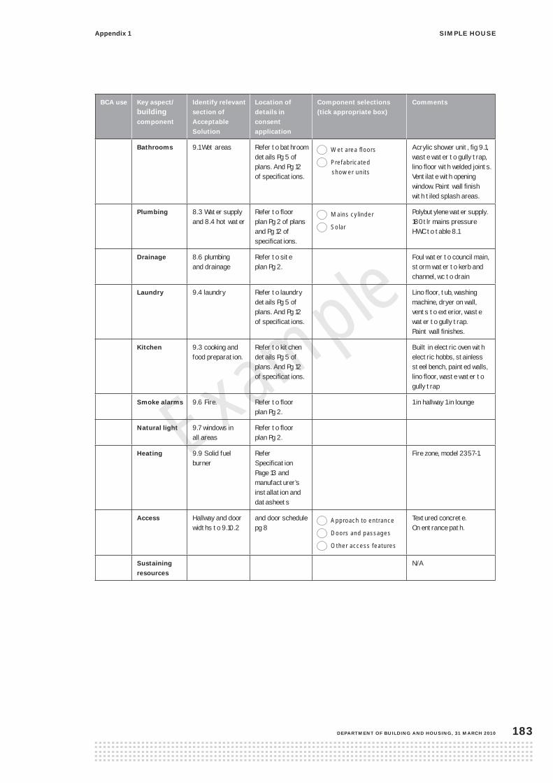
Example
Bca use Key aspect/ building component
identify relevant section of acceptable solution
location of details in consent application
component selections (tick appropriate box)
comments
Bathrooms 9.1 Wet areas Refer to bathroom details Pg 5 of plans. And Pg 12 of specifications.
Wet area floors
Prefabricated shower units
Acrylic shower unit, fig 9.1, waste water to gully trap, lino floor with welded joints. Ventilate with opening window. Paint wall finish with tiled splash areas.
plumbing 8.3 Water supply and 8.4 hot water
Refer to floor plan Pg 2 of plans and Pg 12 of specifications.
Mains cylinder
Solar
Polybutylene water supply. 180tlr mains pressure HWC to table 8.1
Drainage 8.6 plumbing and drainage
Refer to site plan Pg 2.
Foul water to council main, storm water to kerb and channel, wc to drain
laundry 9.4 laundry Refer to laundry details Pg 5 of plans. And Pg 12 of specifications.
Lino floor, tub, washing machine, dryer on wall, vents to exterior, waste water to gully trap. Paint wall finishes.
Kitchen 9.3 cooking and food preparation.
Refer to kitchen details Pg 5 of plans. And Pg 12 of specifications.
Built in electric oven with electric hobbs, stainless steel bench, painted walls, lino floor, waste water to gully trap
smoke alarms 9.6 Fire. Refer to floor plan Pg 2.
1 in hallway 1 in lounge
natural light 9.7 windows in all areas
Refer to floor plan Pg 2.
heating 9.9 Solid fuel burner
Refer Specification Page 13 and manufacturer’s installation and datasheets
Fire zone, model 2357-1.
access Hallway and door widths to 9.10.2
and door schedule pg 8
Approach to entrance
Doors and passages
Other access features
Textured concrete. On entrance path.
sustaining resources
N/A
siMple houseappendix 1
DepartMent of BuilDing anD housing, 31 March 2010 183

31 March 2010, DepartMent of BuilDing anD housing184

siMple houseappendix 2
DepartMent of BuilDing anD housing, 31 March 2010 185
Appendix 2 – Optional design summary – blankuse this table to check if the design fits with the scope outlined in section 1 of the acceptable solution.
Address of proposed work
(a) single storey stand-alone, up to Very High Wind
Zone (50 m/s)
(b) maximum length or width of floor (max 24.0 m)
(c) simple plan shapes
(d) concrete slab or suspended timber floor on piles
(e) maximum 2.0 m finished floor level to adjacent
cleared ground
(f) simple roof forms, incorporating hips, valleys, gables
or mono pitches
(g) eaves minimum 450 mm to all roofs
(h) maximum overall height of 7.0 m from roof apex
from lowest cleared ground level
(i) maximum roof height 3.0 m
(j) roof slope between 10º and 35º
(k) maximum span of roof truss 12.0 m
(l) external walls maximum 2.4 m – other than gable ends
and walls to mono-pitched roofs maximum 4.0 m
(m) timber framing, as specified in this acceptable solution
(n) maximum two wall claddings
(o) no building element located less than 650 mm from
any site boundary

use this table to check if detailed aspects of the design fit within sections 2 – 10.
Bca use Key aspect/ building component
identify relevant section of acceptable solution
location of details in consent application
component selections (tick appropriate box)
comments
site Wind zone (not crest zone)
Corrosion zone
Topography
Ground bearing
Expansive soils
foundation Slab
Isolated footings (posts)
Pile
Wall framing Slab
Isolated footings (posts)
Pile
Gable ends
roof framing Trusses
Skillion roof
roofing Pressed steel tiles
Profiled metal
Concrete tile
cladding 70 mm brick
90 mm brick
Plywood
Fibre cement flat sheet
Weatherboard
Bracing P21 Proprietary
Plywood
Plasterboard
insulation
internal linings
siMple house appendix 2
31 March 2010, DepartMent of BuilDing anD housing186

Bca use Key aspect/ building component
identify relevant section of acceptable solution
location of details in consent application
component selections (tick appropriate box)
comments
Bathrooms . Wet area floors
Prefabricated shower units
plumbing Mains cylinder
Electric
Gas
Drainage
laundry
Kitchen .
smoke alarms
natural light
heating
access Entrance
Doors and passages
Other features
sustaining resources
siMple houseappendix 2
DepartMent of BuilDing anD housing, 31 March 2010 187

31 March 2010, DepartMent of BuilDing anD housing188
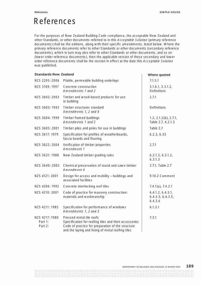
For the purposes of New Zealand Building Code compliance, the acceptable New Zealand and other Standards, or other documents referred to in this Acceptable Solution (primary reference documents) shall be the editions, along with their specific amendments, listed below. Where the primary reference documents refer to other Standards or other documents (secondary reference documents), which in turn may also refer to other Standards or other documents, and so on (lower order reference documents), then the applicable version of these secondary and lower order reference documents shall be the version in effect at the date this Acceptable Solution was published.
standards new Zealand
NZS 2295: 2006 Pliable, permeable building underlays 7.1.5.1
NZS 3109: 1997 Concrete construction 3.1.6.1, 3.3.1.2, Amendments 1 and 2 Definitions
NZS 3602: 2003 Timber and wood-based products for use 2.7.1 in building
NZS 3603: 1993 Timber structures standard Definitions Amendments 1, 2 and 4
NZS 3604: 1999 Timber framed buildings 1.2, 2.1.2(b), 2.7.1, Amendments 1 and 2 Table 2.7, 4.2.1.3
NZS 3605: 2001 Timber piles and poles for use in buildings Table 2.7
NZS 3617: 1979 Specification for profiles of weatherboards, 6.2.3, 6.33 fascia boards and flooring
NZS 3622: 2004 Verification of timber properties 2.7.1 Amendment 1
NZS 3631: 1988 New Zealand timber grading rules 6.2.1.3, 6.3.1.2, 6.3.1.3
NZS 3640: 2003 Chemical preservation of round and sawn timber 2.7.1, Table 2.7 Amendment 4
NZS 4121: 2001 Design for access and mobility – buildings and 9.10.2 Comment associated facilities
NZS 4206: 1992 Concrete interlocking roof tiles 7.4.1(a), 7.4.2.1
NZS 4210: 2001 Code of practice for masonry construction: 6.4.1.2, 6.4.3.1, materials and workmanship 6.4.3.3, 6.4.3.5, 6.4.3.6
NZS 4211: 1985 Specification for performance of windows 6.1.3.1 Amendments 1, 2 and 3
NZS 4217: 1980 Pressed metal tile roofs 7.3.1 Part 1: Specification for roofing tiles and their accessories Part 2: Code of practice for preparation of the structure and the laying and fixing of metal roofing tiles
References
Where quoted
siMple housereferences
DepartMent of BuilDing anD housing, 31 March 2010 189

NZS 4223: Code of practice for glazing in buildings – Part 1: 2008 Glass selection and glazing 9.7.2(a) Part 2: 1985 The selection and installation of manufactured 9.7.2(a) sealed insulating glass units Amendments: 1, 2 Part 3: 1999 Human impact safety requirements 9.7.2(b) Amendment 1 Part 4: 2008 Wind, dead, snow and live actions 6.1.3.2, 9.7.2(c)
NZS 4246: 2006 Energy efficiency – Installing insulation in 2.8.1 Comment residential buildings
NZS 4402: Methods of testing soils for civil engineering Definitions purposes Part 2, Section 2:1986 Test 2.2 Determination of the liquid limit.
NZS 4431: 1989 Code of practice for earth fill for residential 2.1.2(d), 2.1.3.1(c), development 2.1.4.1, 3.2.1.1(b) Amendment 1
NZS 4606: Storage water heaters 8.4.2(a) and (b) Part 1: 1989 General requirements
Amendments 1, 2 and 3 Part 2: 1989 Specific requirements for water heaters with single shells
Amendment A Part 3: 1992 Specific requirements for water heaters with composite shells
Amendment: A
NZS 5261: 2003 Gas installation 8.2.1(a), 9.9.1Amendment 1 Comment (b),
NZS 5262: 2003 Gas appliance safety 8.4.2 (b) and (c) Amendment 1
standards australia
AS 1111: ISO metric hexagon bolts and screws – 2.7.5 Product grades A and B Part 1: 2000 Bolts Part 2: 2000 Screws
AS 1214: 1983 Hot-dip galvanised coatings on threaded fasteners Table 2.3 (ISO metric coarse thread series)
AS 1397: 2001 Steel sheet and strip – Hot-dipped zinc coated Table 2.3, 7.1.6.2(a) or aluminium/zinc-coated 7.2.2.2(b), 7.3.1(c)(i) and (ii), Definitions
AS 1547: 2000 On-site domestic wastewater management 8.4.3.3
AS 1804: 1976 Soft lead sheet and strip Definitions
AS 2049: 2002 Roof tiles 7.4.1.1(b)
AS 2870: 1996 Residential slabs and footings – Construction 3.2.1.1
siMple house references
31 March 2010, DepartMent of BuilDing anD housing190
Where quoted

AS 3566: Screws – Self-drilling – For the building and construction industries Part 2: 2002 Corrosion resistance 6.4.4.6(b), 7.2.3.1,
AS 3730: Guide to the properties of paints for buildings 6.2.2.2(b), 6.3.2.2(b) Part 7: 1992 Latex – Exterior – Flat 6.5.10.3 Part 8: 1992 Latex – Exterior – Low gloss Part 9: 1992 Latex – Exterior – Semi-gloss Part 10: 1992 Latex – Exterior – Gloss
standards australia – new Zealand
AS/NZS 1260: 1999 PVC pipes and fittings for drain, waste 8.6.2(b) and vent applications
AS/NZS 1547: 2000 On-site domestic wastewater management 8.6.8
AS/NZS 1604: Specification for preservative treatment Table 2.7 Part 3: 2002 Plywood
AS/NZS 1734: 1997 Aluminium and aluminium alloys – Flat sheet, Definitions coiled sheet and plate
AS/NZS 1859 Reconstituted wood-based panels Table 2.7, 3.3.15.1(a) Part 1: 2002 Particleboard
AS/NZS 2269: 2004 Plywood – Structural Table 2.7, 3.3.15.1(b)
AS/NZS 2588: 1998 Gypsum plasterboard 4.6.3.2
AS/NZS 2699: Built-in components for masonry construction. Part 1: 2000 Wall ties Table 2.3 Part 2: 2000 Connectors and accessories Definitions Part 3: 2002 Lintels and shelf angles (durability requirements) Table 2.3
AS/NZS 2712: 2007 Solar and heatpump waterheaters – 8.4.2(d) and (e) Design and construction
AS/NZS 2728: 2007 Pre-finished/prepainted sheet metal products 7.1.6.2(a) and (b), for interior/exterior building applications – 7.2.2.2(a) and (b), Performance requirements 7.3.1(d), Definitions
AS/NZS 2908: Cellulose-cement products Part 2: 2000 Flat sheets 6.5.2.1(b)
AS/NZS 2918: 2001 Domestic solid fuel burning appliances – 9.9.1 Comment (a) installation
AS/NZS 3000: 2007 Electrical installations 8.1.1
AS/NZS 3350: Safety of household and similar 8.4.2 electrical appliances Part 2.35: 1999 Particular requirements of instantaneous water heaters
siMple housereferences
DepartMent of BuilDing anD housing, 31 March 2010 191
Where quoted

AS/NZS 3500: National plumbing and drainage code 8.3.2(a), 8.4.2, Part 1: 2003 Water services 8.4.2(c), 8.6.1, Amendment 1 8.6.8 Part 2: 2003 Sanitary plumbing and drainage
Amendment 1 Part 4: 2003 Heated water services
Amendment 1 Part 5: 2003 Domestic installations
AS/NZS 4200: Pliable building membranes and underlays Definitions Part 1: 1994 Materials
Amend 1
AS/NZS 4256: Plastic roof and wall cladding materials Definitions Part 2: 1994 Unplasticized polyvinyl chloride (uPVC) building sheets
AS/NZS 4455: 1997 Masonry units and segmental pavers 6.4.1.4
AS/NZS 4456: 2003 Masonry unit and segmental pavers – 6.4.1.4 Methods of test
Amendments 1 and 2
AS/NZS 4586: 2004 Slip resistance classification of new pedestrian 9.10.1 surface materials
AS/NZS 4671: 2001 Steel reinforcing materials 3.1.7, 3.1.7.2
AS/NZS 4680: 2006 Hot-dip galvanised (zinc) coating on fabricated Table 2.3 ferrous articles
AS/NZS 4936: 2002 Air admittance valves (AAVs) for use in sanitary 8.6.2(a) plumbing and drainage systems
AS/NZS 60335 Household and similar electrical 9.9.1 Comment Part 2.30: 2009 Safety appliance – Particular requirements (c) and (d) for room heaters
international standards
ASTM C1549: 2002 Standard test method for determination of Definitions solar reflectance near ambient temperature using a portable solar reflectometer
ASTM D6134: 1997 Standard specification for vulcanised rubber Definitions sheets used in waterproofing systems
ASTM E96: 1992 Standard test methods for water vapour Definitions transmission of materials
ASTM E903: 1996 Standard test method for solar absorbance, Definitions reflectance and transmittance of materials using integrating spheres
ISO 11600: 2002 Building construction – Jointing products 6.1.2(d)(ii), classification and requirements for sealants Definitions
ISO/TS 15510: 2003 Stainless steels – chemical composition Definitions
Fed.spec TT-5-002230C 6.1.2(d)(ii), Definitions
siMple house references
31 March 2010, DepartMent of BuilDing anD housing192
Where quoted

new Zealand organisations
BRANZ Bulletin 330: 1995 Thin flooring materials – 3.1.10 Preparation and laying
BRANZ Bulletin 411:2001 Recommended domestic 6.2.3 wastewater management
BRANZ House Insulation Guide – 3rd Edition, with 2008 Supplement 2.8.1 Comment
BRANZ Technical paper P21: 1991 A wall bracing test and 4.6.3 evaluation procedure
BRANZ Evaluation Method EM1 Structural joints – strength and Definitions stiffness evaluation
BRANZ Supplement to P21 An evaluation method of P21 test results 4.6.3, 4.6.3.1 for use with NZS 3604: 1990
Ministry of Health: 2005 Drinking Water Standards for New Zealand 8.3.3
Ministry of Health: 2006 Household water supplies: the selection, 8.3.3 operation and maintenance of individual household water supplies
Resource Management (National Environment Standards relating 9.9.1 Comment (a) to certain Pollutants, Dioxins and other Toxins) Regulations: 2004 (NESAQ)
new Zealand legislation
Plumbers, Gasfitters, and Drainlayers Act 2006 8.2.1(b), 8.3.2(b)
siMple housereferences
DepartMent of BuilDing anD housing, 31 March 2010 193
Where quoted

31 March 2010, DepartMent of BuilDing anD housing194

siMple houseDefinitions
DepartMent of BuilDing anD housing, 31 March 2010 195
This is a list of definitions for words or terms relevant to this Acceptable solution.
Definitions
acceptable solution A solution that must be accepted as complying with the Building Code.
adequate Adequate to achieve the objectives of the Building Code.
air admittance valve A valve that allows air to enter but not to escape in order to limit pressure fluctuations with the sanitary plumbing or drainage system.
air seal A continuous seal fitted between window or door reveal and the surrounding wall framing to prevent the flow of air into the interior of the building.
aluminium flashings Aluminium flashings shall be a minimum thickness of 0.7 mm, and formed from 5000 series in accordance with AS/NZS 1734 and, where pre-painted, have a factory-applied finish complying with AS/NZS 2728.
aluminium-zinc coated steel flashings Aluminium-zinc coated steel flashings shall be:
(a) BMT 0.55 mm minimum of steel for flashings generally
(b) BMT 0.4 mm of steel for roll-formed roll-top ridge flashings
(c) in aluminium-zinc coating of AZ150 to AS 1397, with a factory-applied finish in accordance with AS/NZS 2728 Type 4, and in sea spray zone and corrosion zone 1 the factory-applied finish shall be Type 5 minimum.
apron flashing A near flat or sloping flashing with a vertical upstand, used at junctions between roofs and walls.
Backing rod Closed cell polyethylene foam (PEF) rod inserted into gap to provide backing support for foam air seal or sealant.
Baluster An infil member that provides support for the top and bottom rails of a barrier.
Base metal thickness (BMT) The thickness of the bare or base metal before any subsequent coating, such as galvanising.
Batten See ceiling batten, tile batten.
Bird’s beak A double fold applied to the edge of a horizontal metal flashing to stiffen the edge and to assist in deflecting moisture away from the cladding system. Refer also to kick out and drip edge.
Blocking Solid timber having the same depth as the joists and set at right angles between the joists to stiffen and prevent them from buckling
Bond, running or stretcher The bond when the units of each course overlap the units in the preceding course by between 25% and 75% of the length of the units.
Bottom plate A plate placed under the bottom end of studs.
Boundary joist A joist running along the outer end of the floor joists.
Bracing Any method employed to provide lateral support to a building.
Bracing capacity Strength of bracing of a whole building or of elements within a building. Bracing capacity is measured in bracing units (BUs).
Bracing demand The horizontal forces to be resisted by a whole building or by an element within a building. These horizontal forces are a result of wind or earthquake action. Bracing demand forces are measured in bracing units (BUs).
Bracing line A line along or across a building containing wall bracing elements.
Bracing rating The lateral load resistance assigned, for example, to a wall bracing system.
Bracing unit (Bu) A bracing unit is a measure of:
(a) the horizontal force (bracing demand ) on the building (1 kiloNewton is equal to 20 bracing units)
(b) the resistance to horizontal force (bracing capacity) of building elements.

siMple house Definitions
31 March 2010, DepartMent of BuilDing anD housing196
Building has the meaning given to it by sections 8 and 9 of the Building Act 2004.
Building code or new Zealand Building code means the regulations made under section 400 of the Building Act 2004.
Building consent A consent issued by a building consent authority for building work to begin in accordance with the approved plans and specifications.
Building consent authority (Bca) A person whose name is entered in the register referred to in section 273(1)(a) of the Building Act 2004.
Building element Any structural and non-structural component or assembly incorporated into or associated with a building. Included are fixtures, services, drains, permanent mechanical installations, glazing, partitions, ceilings and temporary supports.
Building wrap or building underlay See wall underlay.
Butyl rubber and epDM flashings Butyl rubber and EPDM flashings shall be a minimum thickness of 1.0 mm, and shall comply with the following parts of Table 1 in ASTM D6134:
(b) tensile strength
(c) elongation
(d) water absorption
(e) water vapour transmission
(f) heat aging followed by:
i) tensile strength
ii) elongation.
capacity The load resistance of a connector or fixing.
ceiling batten A horizontal member fixed below rafters, or truss bottom chords to which the ceiling lining is attached.
cladding The exterior weather-resistant surface of a building.
cladding system The weatherproof wall or roof enclosure of a building, including underlays, claddings and their fixings, windows, doors and all penetrations, flashings, seals, joints and junctions.
cleared ground level (cgl) The ground level after completion of site excavation and removal of all harmful material, but before excavation for foundations.
concrete slab shrinkage control joint A line along which the horizontal strength of the slab is deliberately reduced so that any shrinkage in the slab will result in a crack forming along that line.
control joint A joint designed to prevent damage by accommodating movement. See also expansion joint.
D A deformed reinforcing bar of the stated diameter in millimetres.
Damp-proof course (Dpc) A narrow strip (generally up to 300 mm wide) of durable vapour barrier greater than 90MN s/g to ASTM E96 and placed between building elements to prevent the passage of moisture from one element to another.
Damp-proof membrane (DpM) A sheet material, coating or vapour barrier, having a low water vapour transmission, and used to prevent water and water vapour movement through concrete in contact with the ground (also known as a concrete underlay).
Deck An open platform projecting from an exterior wall of a building and supported by framing.
Diagonal brace A member of a framed building fixed diagonally and used to resist tension or compression or both.
Diameter (or bore) The nominal internal diameter.

siMple houseDefinitions
DepartMent of BuilDing anD housing, 31 March 2010 197
Direct fixed A term used to describe a wall cladding attached directly to the wall framing, without the use of a drained cavity.
Discharge pipe Any pipe that is intended to convey discharge from sanitary fixtures or sanitary appliances.
Drain A pipe normally laid below ground level including fittings and equipment, and intended to convey foul water or surface water to an outfall.
Drain vent pipe Any pipe which is intended to permit the movement of air into and out of the drain and sewer.
Drip edge Fold(s) applied to the edge of a metal flashing to deflect moisture away from the cladding system. Refer also to bird’s beak and kick-out.
Dwang or nogging A short horizontal member fixed between framing timbers.
eaves That part of the roof construction, including cladding, fascia and gutter, that extends beyond the exterior face of the wall.
eaves bearer or soffit bearer or sprocket A horizontal member attached to the end of a truss or a rafter and to a stud, or a ribbon board, or a soffit plate, and to which the eaves lining is attached.
epDM Ethylene Propylene Diene Monomer – a thermosetting synthetic rubber. See butyl rubber.
expansion joint A joint designed to prevent damage by accommodating movement. See also control joint.
external wall An outer wall of a building.
finished ground level (fgl) The level of the ground after all backfilling, landscaping, and surface paving have been completed.
fixture An article intended to remain permanently attached to and form part of a simple house.
fixture discharge pipe A discharge pipe that is used to convey waste from a single sanitary fixture or sanitary appliance to a branch discharge pipe, a discharge stack or directly to a drain. It does not include any pipes forming part of a sanitary appliance.
flashing A component formed from a rigid or flexible waterproof material that drains or deflects water back outside the cladding system.
flexible flashing tape A flexible self-adhesive waterproof tape. Usually used as an accessory for wall underlays to seal corners and intersections
floor waste gully A disconnector gully for installation inside a building, for use with a floor grating or waste outlet fitting on a riser pipe and with provision, where required, for connection of waste pipes for sanitary fixtures.
footing That portion of a foundation bearing on the ground and any adjoining portion that is reinforced so as to resist the bearing forces.
foul water The discharge from any sanitary fixture or sanitary appliance.
foul water drainage system Drains, joints and fittings normally laid underground and used specifically for the conveyance of water from the plumbing system to an outfall.
foundation Those parts of a building transmitting and distributing loads to the ground through a footing.
framing Timber members to which lining, cladding, flooring or decking is attached; or which are depended upon for supporting the structure, or for resisting forces applied to it.
gable Triangular part of an external wall between the planes of the roof and the line of the eaves.

siMple house Definitions
31 March 2010, DepartMent of BuilDing anD housing198
galvanised steel flashings Galvanised steel flashings shall be:
(a) BMT of 0.55 mm minimum for flashings generally
(b) BMT of 0.4 mm minimum for roll-formed roll-top ridge flashings
(c) Hot-dipped zinc coated Z275 with a factory-applied finish that complies with AS/NZS 2728 Type 4, and in Sea Spray and corrosion Zone 1 the factory-applied finish shall be Type 5 minimum.
good ground Any soil or rock capable of permanently withstanding an ultimate bearing pressure of 300 kPa (ie, an allowable bearing pressure of 100 kPa using a factor of safety of 3.0) but excluding:
(a) potentially compressible ground such as top soil, soft soils such as clay which can be moulded easily in the fingers, and uncompacted loose gravel which contains obvious voids;
(b) expansive soils being those that have a liquid limit of more than 50% when tested in accordance with NZS 4402 Test 2.2, and a linear shrinkage of more than 15% when tested from the liquid limit in accordance with NZS 4402 Test 2.6, and
(c) any ground which could foreseeably experience movement of 25 mm or greater for any reason including one or a combination of: land instability, ground creep, subsidence, seasonal swelling and shrinkage, frost heave, changing ground water level, erosion, dissolution of soil in water, and effects of tree roots.
(Note that soils, excepting those described in (a), (b) and (c) above, tested with a dynamic cone penetrometer in accordance with NZS 4402 Test 6.5.2, shall be acceptable as good ground for building foundations if penetration resistance is no less than:
(i) 3 blows per 75 mm at depths no greater than the footing width
(ii) 2 blows per 75 mm at depths greater than the footing width.
Depths shall be measured from the underside of the proposed footing.)
gross floor area The area contained within the outside face of the exterior timber wall framing of a simple house.
ground level See cleared ground level, finished ground level.
gully trap A fitting designed to prevent foul air escaping from the foul water drainage system and used to receive the discharge from waste pipes.
habitable space A space used for activities normally associated with domestic living, but excludes any bathroom, laundry, water closet, pantry, walk-in wardrobe, corridor, hallway, lobby, clothes-drying room, or other space of a specialised nature occupied neither frequently nor for extended periods.
handrail A rail to provide support to, or assist with the movement of a person.
household unit For a simple house, means a building or part of a building that is used or intended to be used for residential purposes.
impervious That which does not allow the passage of moisture.
internal wall A wall other than an external wall.

siMple houseDefinitions
DepartMent of BuilDing anD housing, 31 March 2010 199
Kick out See bird’s beak
lead flashings Lead sheet flashings that:
(a) comply with AS 1804, and
(b) have a minimum unit mass of 17 kg/m².
lightweight wall cladding Timber weatherboard (bevel-back or rusticated) or flat sheet (plywood or fibre-cement) wall claddings for use in this Acceptable Solution.
lining The rigid sheet covering for a wall, ceiling or other interior surface.
lintel A horizontal framing member spanning an opening in a wall.
loadbearing stud A stud in a loadbearing wall.
loadbearing wall A wall supporting vertical loading from a roof.
loaded dimension The loaded dimension of structural elements which support other members at right angles. Refer to Figure 5.2.2.
M A steel bolt of the stated diameter in millimetres.
Masonry veneer Clay or concrete block veneer cladding.
Member span The clear distance between supports, measured along the member.
Msg Machine stress graded refers to timber that is initially sorted by machine, calibrated to NZS 3603. See also Vsg.
network utility operator A person who:
(a) undertakes or proposes to undertake the distribution or transmission by pipeline of natural or manufactured gas, petroleum, or geothermal energy, or
(b) operates or proposes to operate a network for the purpose of:
(i) telecommunication as defined in section 5 of the Telecommunications Act 2001, or
(ii) radio communications as defined in section 2(1) of the Radiocommmunications Act 1989, or
(c) is an electricity operator or electricity distributor as defined in section 2 of the Electricity Act 1992 for the purpose of line function services as defined in that section, or
(d) undertakes or proposes to undertake the distribution of water for supply (including irrigation), or
(e) undertakes or proposes to undertake a drainage or sewerage system.
nogging See dwang
non-loadbearing stud A stud in a non-loadbearing wall.
non-loadbearing wall A wall other than a loadbearing wall.
outfall That part of the disposal system receiving surface water or foul water from the drainage system. For foul water, the outfall may include a sewer or a septic tank. For surface water, the outfall may include a natural water course, kerb or channel, or soakage system.
plate A timber member supported by a foundation or studs to support and distribute the load from floors, walls, roofs or ceilings. See bottom plate, top plate.
plumbing system Pipes, joints and fittings, laid above ground and used for the conveyance of foul water to the foul water drain and including vent pipes.
post An isolated vertical member acting as a support.

siMple house Definitions
31 March 2010, DepartMent of BuilDing anD housing200
proprietary fasteners Proprietary fasteners may be used where the fixing capacity of fixings are specifically identified in this Acceptable Solution.
Manufacturers of a timber connector or fixing shall provide the following information on each package of fixings, or on a securely attached label:
(a) the name, or registered trade name, or make and address of manufacturer
(b) the materials used in manufacture including fasteners and corrosion protection
(c) the load capacity of the timber connector or fixing in kN determined in accordance with the following equation:
R = w x Qk x n x k
Where:
R = connector capacity in kN w = capacity reduction factor
from NZS 3603 Qk = characteristic value obtained
by test in accordance with BRANZ Evaluation Method EM1 or AS/NZS 2699: Part 2 as appropriate
n = number of tested elements making up the complete joint
k = modification factors from NZS 3603 (Section 4) as appropriate to specific application.
(d) fastener’s requirements
(e) details of intended use
(f) durability in accordance with Paragraph 2.5.4.
purlin Includes tile batten. A horizontal member laid to span across rafters or trusses and to which the roof cladding is attached.
r A plain round reinforcing bar of the stated diameter in millimetres.
rafter A framing timber normally parallel to the slope of the roof and providing support for the purlins or roof covering, or ceiling lining.
reinforcement Any form of reinforcing rod, bar or mesh that complies with the relevant requirements of NZS 3109.
ribbon board Includes soffit plate. A horizontal framing timber secured to, or checked into, the edges of studs and supporting eaves bearers.
ridge beam A single beam that supports rafters of a skillion roof.
roof underlay An absorbent, permeable paper that absorbs or collects condensation or water that may penetrate the roof cladding.
The roof underlay shall have the properties in Table 23 of the Acceptable Solution E2/AS1 for Building Code Clause E2 External Moisture:
(a) absorbency of 100 g/m2 or greater
(b) vapour resistance 7 MN s/g or less
(c) water resistance of 100 mm or greater
(d) pH of extract of between 6.0 and 9.0
(e) shrinkage no more than 0.5%
(f) mechanical edge tear and tensile strength to AS/NZS 4200.
roof That part of the building having its upper surface exposed to the outside and at an angle of between 10º and 35º to the horizontal. See skillion roof.
running bonds, See bond
r-value The common abbreviation for describing the values of both thermal resistance and total thermal resistance.
sanitary appliance An appliance which is intended to be used for sanitation, but which is not a sanitary fixture, for example a washing machine.
sanitary fixture Any permanently attached fixture to a building which is intended to be used for sanitation.

siMple houseDefinitions
DepartMent of BuilDing anD housing, 31 March 2010 201
sealant A flexible neutral cure sealant for gap filling and weatherproofing that complies with:
(a) Type F, Class 20 LM or 25 LM of ISO 11600, or
(b) low modulus Type II Class A of Federal Specification TT-S-00230C.
simple house A house that is described in Section 1 of this Acceptable Solution.
sitework Work on a building site, including earthworks, preparatory to or associated with the construction, alteration, demolition or removal of a building.
skillion roof A pitched roof where the ceiling lining is parallel and close to the roof cladding. The roof may be mono-pitch or may consist of more than one roof plane. These roofs may have rafters exposed below the ceiling.
soffit bearer See eaves bearer.
soffit plate See ribbon board.
soft edge A compatible soft edging seamed onto flashings to provide closure to profiled roof cladding.
spacing or spaced The distance at which members are spaced, measured centre to centre.
spans See member span and support span.
specific design Design and detailing of a proposed building or parts of a building, demonstrating compliance with the Building Code, that shall be provided to the building consent authority for assessment and approval as part of the building consent process. Buildings, or parts of buildings, requiring specific design are beyond the scope of this Acceptable Solution.
stainless steel flashings Stainless steel flashings shall be:
(a) minimum thickness of 0.45 mm, and
(b) Type 304 or 316 stainless steel in accordance with Table 1 of ISO/TS 15510.
stretcher bonds, See bond
stud A vertical framing member.
support span A clear distance along a member between supports, measured in plan (horizontally).
surface water All naturally occurring water, other than sub-surface water, which results from rainwater on the site or water flowing onto the site, including that flowing from a drain, stream, river, lake or sea.
territorial authority City or district council (as named in Schedule 2, Part 2 of the Local Government Act 2002) responsible for community wellbeing and development, environmental health and safety (including building control, civil defence, and environmental health matters), infrastructure (roading and transport, sewerage, water/stormwater), recreation and culture, and resource management including land use planning and development control.
thermal resistance The resistance to heat flow of a given component of a building element. It is equal to the temperature difference (°C) needed to produce unit heat flux (W/m2) through unit area (m2) under steady conditions. The units are °Cm2/W.
tile batten See purlin.
top plate A plate placed over the top end of studs.
total wall area In relation to a simple house, means the sum (expressed in square metres) of the following:
(a) the wall area of the building, or
(b) the area (expressed in square metres) of all vertical glazing in external walls of the building.
trapezoidal A type of profiled metal roof cladding with symmetrical or asymmetrical crests, with troughs between the crests.

siMple house Definitions
31 March 2010, DepartMent of BuilDing anD housing202
trimmer A member supporting the wall framing beneath, or over an opening in a non-loadbearing wall and carrying wind loads to the trimmer studs.
trimmer stud A stud located on the side of an opening.
universal access Where elements and spaces are accessible to and usable by people of all ages and abilities to the greatest extent possible.
upVc flashings uPVC flashings shall be a minimum of 0.75 mm thick and:
(a) comply with the requirements of the following Clauses of AS/NZS 4256: Part 2:
ii) Clause 9.2 Impact resistance
iii) Clause 9.3 Tensile strength
iv) Clause 9.4 Colourfastness and impact resistance following ultraviolet light exposure.
(b) where exposed to the weather, shall also comply with Section 8 of AS/NZS 4256: Part 2.
(c) have a finish colour with a reflectance of 40% or more, when measured in accordance with ASTM C1549 or ASTM E903.
Valley board A board laid to support a valley gutter.
Valley gutter A gutter running down the valley formed by the intersection of two pitched roof surfaces.
Vent pipe A pipe for the purpose of protecting water seals that at its upper end is either open to the atmosphere or fitted with an air admittance valve, and at its lower end is connected to a discharge pipe.
Vsg Visual stress graded, refers to verified timber that is initially sorted visually in accordance with NZS 3603. See also Msg.
Wall bracing element A section of wall that performs a bracing function.
Wall underlay An absorbent synthetic wrap used as part of the wall cladding system to assist the control of moisture by ensuring moisture which may occasionally penetrate the wall cladding is directed back to the exterior of the building.
The wall underlay shall have the properties in Table 23 of the Acceptable Solution E2/AS1 for Building Code Clause E2 External Moisture:
(a) absorbency – no requirement
(b) vapour resistance 7 MN s/g or less
(c) water resistance of 20 mm or greater
(d) pH of extract of between 6.0 and 9.0
(e) shrinkage no more than 0.5%
(f) mechanical edge tear and tensile strength to AS/NZS 4200.
Waste pipe A discharge pipe that conveys the discharge from waste water fixtures to a gully trap or floor waste gully.
Waterproof and waterproofing The complete and total resistance of a building element to the ingress of any moisture.
Water seal The depth of water that can be retained in a water trap.
Water trap A fitting designed to retain a depth of water that prevents foul air and gases escaping from the plumbing system or foul water drainage system and entering a building.
Weathertightness and weathertight Terms used to describe the resistance of a building to the weather.
Wet area An area within a building supplied with water from a water supply system including bathrooms and showers, laundries, sanitary compartments and kitchen areas.
Wire dog Galvanised or stainless steel wire, D or Z shaped nail, spiked at each end. Used for fixing timber together to resist uplift.

![INDEX [] · 2014-12-13 · architectural solutions that are perfectly acceptable at the size of a simple structural system like house become physically impossible at the scale of](https://img.pdfslide.net/doc/110x75/5e75a7993c184b6824402176/index-2014-12-13-architectural-solutions-that-are-perfectly-acceptable-at.jpg)