Embed Size (px)
Citation preview

Paper ID #34572
Simulation and Validation of Battery Management System
Mr. Edmund Huminski, United States Coast Guard Academy
Edmund Huminski is a fourth year Electrical Engineering student at the United States Coast GuardAcademy. Edmund was born and raised in Madison, Connecticut. Edmund is an avid runner and amember of the Marathon club at USCGA. After graduation Edmund hopes to be stationed on a NationalSecurity Cutter in California.
Salena Marie BantzMr. Joseph Roth, United States Coast Guard Academy
Senior at the United States Coast Guard Academy completing his final Research and Design Project.
Mr. Liam Scott CaroDr. Tooran Emami, United States Coast Guard Academy
Tooran Emami is an associate professor of Electrical Engineering at the U. S. Coast Guard Academy.She received M.S. and Ph.D. degrees in Electrical Engineering from Wichita State University in 2006and 2009, respectively. Dr. Emami was an adjunct faculty member of the Department of ElectricalEngineering and Computer Science at Wichita State University for three semesters. Her research interestsare Proportional Integral Derivative (PID) controllers, robust control, time delay, compensator design, andfilter design applications, for continuous-time and discrete-time systems.
Mr. David Fournier, United States Coast Guard Academy
Holds a BA and MS from Southern New Hampshire University. Served twenty years in the US CoastGuard as an Electronics Technician. Currently manages, develops, and instructs labs for Electrical Engi-neering and Cyber Systems and teaches cyber security to cadets at the US Coast Guard Academy.
c©American Society for Engineering Education, 2021

Simulation and Validation of Battery Management System
Abstract
This paper presents the process and results of the simulation and validation of a battery
management system. The goal of this project is to design a battery management system and
power management system for use in a Hybrid Electric Vehicle (HEV). The system must be
capable of seamlessly transitioning between two power sources and must also contain a
controller capable of automatically executing this switch, based on user defined conditions. The
system will also deliver live State of Charge (SOC) and State of Health (SOH) data from the
system’s battery bank. The primary energy sources used in this project are Ni-MH rechargeable
batteries connected modularly to form component packs, which are then connected to form a
larger bank. The loads are 2 sets of TT DC Gearbox Motor 3-6V Gear with Tire Wheel that are
connected to a Pulse Width Modulation (PWM) circuit to operate at different speeds. Analog and
digital sensors are connected to read voltage and current data from the system, which is then
analyzed on a connected computer. The current sensor is a Gikfun 20A Range Current Sensor
ACS712 and the voltage sensor is a Diymall Voltage Sensor DC0-25v. The real time
measurement data is analyzed and plotted for the current, voltage, and power in MATLAB. The
design and system simulations are constructed using MATLAB Simulink.
The motivation of this project is to develop knowledge and skills in battery management
and power storage systems. To remain technologically competitive with the maritime sector at
large, the Coast Guard must evaluate the possible applications of Electric Vehicles (EVs) and
Fuel Cell Hybrid Electric Vehicles (FCHEVs) in the operational and support domains. Carried
out at the United States Coast Guard Academy, this project was completed by a team of
undergraduate Electrical Engineering students as a culminating project in earning their degrees.
I. Introduction & Background Research
Popular interest in EVs has increased considerably in the past decade. Companies like
Tesla have captured the public’s curiosity by delivering on their promise to produce high
efficiency performance cars on a large scale. EVs possess several advantages over internal
combustion engine vehicles to include lower upkeep cost, the ability to produce a tremendous
amount of torque instantaneously, and higher efficiency. As this technology transitions into the
maritime industry, the USCG Maritime Safety Center has begun taking interest and provided
direction and support to this project. Their vested interest lies in the Coast Guard’s role as a
regulator, operator, and inspector for current commercial vessels. Education about hybrid power
systems helps the Maritime Safety Center develop policy for future enforcement and prevention
as this technology continues to develop. The design and build team for this project will develop
technical expertise in the field of FCHEV by building a system capable of switching between
hydrogen fuel cell power and battery power.
Hybrid electric vehicles (HEVs) have also found use in a variety of applications, as the
comparatively low energy density and limited practical range of EV power systems can be offset
by another power source. Concerns regarding climate change have only increased interest and
investment in these systems. Companies in the trucking industry are working to implement more
efficient and sustainable vehicles; developers have produced semi-trucks capable of hauling
loads 300 miles emission free, fueled by a hydrogen fuel cell and supplemented by batteries [4].
Toyota has applied this technology to the maritime industry, placing a similar hydrogen fuel cell
in a vessel. Successful testing was completed, demonstrating FCHEVs possible application in the
maritime industry [2]. As with any new ideas, problems have arisen along the way. One is the
lack of hydrogen fueling stations to refuel the cells when necessary. Another is the relationship
between batteries and the fuel cell. All developers are continuing to explore which power source,
battery or fuel cell, is best suited as the primary power source. While hydrogen fuel cells are
efficient, they cannot provide instantaneous increase in power, say if a vehicle needed to
accelerate, whereas battery power can. This group of students, in the development of FCHEV,
explore these problems and determine how battery configuration, management, and switching
system can provide solutions.
A key component to any FCHEV is the Battery Management System (BMS). A capable
BMS will be able to monitor the state of charge (SOC) and state of health (SOH) of batteries
connected to it. SOC describes the amount of potential energy the battery has remaining in a
single discharge [1], like the gas gauge on a car describing the amount of fuel left. SOH
describes the ability of the battery to maintain an amount of charge as it is discharged and
charged multiple times. As a battery undergoes cycles of charge and discharge, its ability to hold
charge decreases. This must be measured and understood so the system can remain as efficient as
possible.
SOC estimation may be accomplished by a variety of processes and algorithms. Three
SOC estimation techniques are discussed in [6]. The first, and least accurate technique, uses the
Electrical Equivalent Circuit (EEC) model, a circuit built to replicate the interior of a battery and
charge and discharge it over time. The second technique uses Coulomb Counting (CC), the
process of measuring a battery’s charging and discharging current over time in order to calculate
total energy change within the cell. To use CC, the initial SOC and battery capacity must be
known. This method of SOC estimation has the benefit of being generally accurate and simple to
implement, but it does not account for aging or temperature changes and has no process for data
validation. The third reviewed technique is the Extended Kalman Filter Algorithm (EKF). The
EKF utilizes state estimation to iteratively correct projected state of charge, producing the most
accurate SOC estimations, with less than 1% error [6].
A BMS must also control the flow of energy into, though, and out of a battery bank. It
does this by working with charging infrastructure, balancing energy between cells in the pack,
and ensuring the cells do not exceed their maximum rated parameters. When designing a BMS,
design considerations must be made for cell balancing. Cell balancing is the process of
equalizing charge across all cells within a battery bank, either through dissipation as heat or
through the transfer of energy from high power cells to low power cells. To better understand the
mechanics of cell balancing, the design team reviewed the research of B. Yildirim et al. found in
reference [3]. This article covers three methods of cell equalization in battery energy storage
systems (BESS). Cell balancing is an integral component to maintaining SOH. While cells of the
same voltage may be used in a system, “manufacturing and thermal variations, differences in
internal impedances, and self-discharging rates” will cause variation between the actual voltages
of individual cells [3]. If cells are not balanced, the entire cell network is handicapped, losing
energy due to inefficiency, degrading individual cell health, and in extreme cases, causing
dangerous explosions.
Of the three cell balancing methods covered in [3], dissipative balancing is simplest to
implement. A dissipative balancing network is constructed by placing resistors in parallel across

each cell. Voltage for each cell will converge with all others in the network as the higher energy
cells dissipate more energy through the resistors than the lower energy cells. Higher relative
energy means higher relative voltage, which in turn will result in more heat energy dissipated
through a cell’s respective resistor [3]. While dissipative balancing is simpler than other
methods, it is also less efficient. Excess energy within cells is dissipated as heat and therefore is
lost. Other methods are needed if efficiency is imperative.
Capacitor-based energy transfer is a more efficient solution. Instead of dissipating excess
energy as heat, the energy is transferred to other cells through capacitors. While the use of
capacitors does increase efficiency, it has limitations. The most common capacitor-based energy
transfer system is a Switched Capacitor (SC) network. In this system, energy is only able to be
transferred to adjacent cells. The result is a significant increase in the time required to balance
cells. Additionally, capacitor-based solutions will balance voltage, not SOC. This is usually not
the most efficient solution due to intrinsic resistances of cells possibly causing an imbalance [3].
Runtime balancing is by far the most efficient cell balancing solution, but it is also the
most complex. This method relies on connecting each cell to “individual low power converters,
with each converter connected in series to increase overall voltage” [3], thus the solution
balances the SOC of all cells. Consequentially, it is incredibly efficient. With this method the
system operator can control the flow of current and can bypass faulty cells which increases
reliability. The disadvantages to runtime balancing included increased complexity and high
implementation cost. Further information regarding runtime balancing is available in reference
[6].
All battery management systems must control the current sent and voltage available to a
load, but the BMS in hybrid systems must also balance the batteries’ power with power from
additional energy sources. This application of BMSs was of interest to the design team, as the
BMS’ final implementation will be in a hybrid fuel cell vehicle. Existing studies were reviewed
to better understand the breakdown of power usage in hybrid systems. A study by C. Qian et al.
used a fuel cell for the main power supply and a battery in parallel as the auxiliary power supply
[7]. The battery was used to negate the impact of the slow response time characteristic of a fuel
cell which causes the fuel-starvation phenomenon. In this system, batteries absorbed or supplied
momentary power when the system had a sudden change in load. The control system was defined
by breaking the system down into four energy flow conditions: steady state, transient
underpower, auxiliary source charge, and cold start and light load conditions. Under the steady
state condition, the fuel cell supplies all power for the load. In transient underpower mode, the
fuel cell and battery will supply power to the load at the same time. When the fuel cell has
enough available power to charge the battery and supply power to the load, the system is in
auxiliary source charge condition. The last mode, cold start and light load mode, exists during
the start-up process for the fuel cell because the fuel cell cannot start with a load [7].
To facilitate switching between these conditions, the system developed by C. Qian et al.
measured SOC and load power [7]. The study developed a control system that used various loops
to control fuel cell current, charge current of battery, SOC of battery, input current, and bus
voltage. The feasibility of the study’s control system and voltage bus performance was proven by
creating a simulation model in PSIM software. The capstone group intends to model the battery
management system and the active control system through Simulink. This study gave one
approach to how a power switching system for a FCHEV could be controlled [7]. A concept

from this approach that could be used for the FCHEV capstone project is to break the control
system down into four energy flow conditions. This requires accurate measurement systems to
determine the operating mode and a response algorithm to each energy flow mode.
II. Objective
The goal of this project was to design, build, and test a hybrid fuel cell and battery power
plant system. To achieve this goal the group decided to create a BMS that manages and runs a
vehicle with four motors using a hydrogen fuel cell and battery bank as power sources. The
main decision components can be categorized as follows: battery/motor configuration, cell
balancing strategy, the BMS, and the power switching scheme. Additionally, the team
endeavored to model the system using MATLAB Simulink, allowing the whole system to be
shown and tested virtually via desktop simulation.
Keeping these necessary components of the system in mind, the group developed the
following design steps to complete the overall project.
1. Review literature relating to battery management and learn about the fundamentals
necessary for developing one’s own system.
2. Take measurements from the Ni-MH cells that would be used in the final product.
Plot their discharge curves and record their no-load current.
3. Use MATLAB to adapt a SOC algorithm for use in the final product.
4. Use MATLAB Simulink to determine the optimal configuration of the Ni-MH cells
for use in the final product.
5. Use MATLAB Simulink to design a cell balancing system for use in the final
product.
6. Design and build a Power Switching System capable of seamlessly and automatically
switching between power sources.
7. Design and build a Pulse Width Modulation circuit for use in controlling the speed of
the motors when running.
An effective BMS ensures maximum performance, safe operation, and optimal life span
and power flow in a battery powered system. A reliable stream of data from the battery bank is
essential to these design parameters. Using voltage and current measurements from the battery
bank, the system will calculate and monitor SOC.
Configuring connections between cells is also vital to the system’s safe and efficient
operation. The final objective is system modeling. An accurate model in software is necessary to
run tests and determine optimal configuration. This model needs to mirror the physical system
design. The Ni-MH batteries and brushless DC motors must be correctly modeled to validate
data from the physical system tests with that in Simulink. A model for various configuration
designs must also be developed to determine the optimal configuration so the system.
During the Fall semester an emphasis was placed on the battery portion of the system; in
the Spring semester the hydrogen fuel cell was implemented as the secondary power source.
Some constraints placed upon the group included irregular time in the lab due to COVID
protocols and a shorter semester. The group is on schedule for completing three of the four main
objectives (system configuration, switching scheme, and modeling) by the end of the semester.
Further work must be done for the BMS because the SOC algorithm is not reliable for different
load conditions by observing current alone.
III. System Design
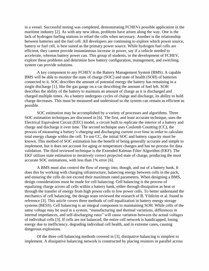
The main considerations covered in the system design include battery cell configuration,
cell balancing strategy, SOC estimation for the BMS, and the power switching scheme. The
prototype design for the Hybrid Electric Vehicle’s battery bank is shown in Figure 1. This
battery bank’s cell configuration is optimized to allow charging and cell balancing while
supplying enough current to the load. The battery bank will be built from (N) packs with (M)
cells per pack. The values of N and M will be determined based upon the current and voltage
required by the motor we use in our final design. The N packs will be connected in parallel, and
the M cells within each pack will be connected in series. Cell balancing will take place between
the packs connected in parallel. A switched capacitor system will be used to transfer the energy
between the packs. Finally, each of the packs will be connected to a dedicated controller for
charging, which will shut off current to a pack when it is fully charged to prevent overcharging.
The BMS design also makes considerations for cell balancing, charging, and maximum
available power. What these three elements of the system have in common is that they are all
related to the configuration of individual cells within the system. Any one of these three design
components can be accomplished relatively easy given the correct cell configuration, but for
each component the ideal configuration is wildly different. For example, when executing cell
balancing, all cells will be in series, so energy can be easily transferred between adjacent cells.
The issue with having cells solely in series is that the battery bank is then handicapped in the
amount of current it can provide. To provide the maximum current, the cells would all be placed
in parallel. The issue with the cells all being placed parallel is that it becomes much more
difficult to charge them. To charge the Ni-MH cells, one runs current backwards into the positive
terminal. If the cells are in parallel, the cell with the lowest internal resistance will charge to near
completion before the other cells start to charge. Overcharging poses significant dangers for Ni-
MH batteries, thus requiring additional design considerations to prevent it. Evidently, cell
balancing, charging, and maximum available have conflicting requirements for their simplest
implementation. The team dedicated significant time to designing a cell configuration that would
allow for all three of these objectives, which can be seen in Figure 1.
Figure 1 – Hybrid Fuel Cell Battery Bank Prototype Design

The system will be able to automatically switch from the batteries (primary power
source) to the hydrogen fuel cell (auxiliary power source) once the batteries drop below their
determined minimum SOC. Additionally, the system will read in current and voltage data of the
battery bank via Arduino sensors. Then, using the enhanced CC algorithm, SOC will be
determined in MATLAB. A block diagram for the algorithm logic is shown below in Figure 2
[5]. In this approach, the battery is marked as fully drained at a specific cut-off voltage and the
SOC is then set to zero. At this empty state, the cumulative depth of discharge (DOD) value is
calculated and used to define the current maximum releasable capacity, a parameter that informs
SOH which prevents cumulative error over time as battery performance degrades. Once the SOC
has met the criteria to switch to the auxiliary source, MATLAB code will execute power
switching. The Arduino will output a pulse-width modulated (PWM) signal that will directly
feed into the hardware for the power switching circuit.
Figure 2 – Flowchart of enhanced CC Algorithm [5]
The battery switching scheme must be able to seamlessly switch between two DC power
sources. For the continuation of this project, these power sources will a hydrogen fuel cell and a
smart battery bank. Currently, the system is simplified, switching only between two battery
banks. This will allow the design team to refine the power switching system and increase its
reliability, while allowing for the incorporation of the hydrogen fuel cell later.
The power switching circuit uses metal oxide silicon field effect transistors (MOSFETs).
These transistors work on three pins: gate, drain, and source. Current will flow through the
MOSFET if a specified threshold voltage is applied to the gate pin. The MOSFET that we chose
has a threshold voltage of two volts. Once the gate has been supplied a two volt signal it will
allow current to flow between the drain and source pins. The drain side is connected to the

battery bank or the hydrogen fuel cell. The power switching system is currently in the prototype
phase. In the prototype there are two MOSFETs, and each switch on an LED. The Arduino will
send PWM signals through RC filters that filter it to a DC voltage signal. The voltage being
supplied to the gate must be constant so that the DC power source on the drain side of the
transistor remains on.
One of the benefits of the chosen power switching design is that it allows for
simultaneous use of the power sources. Both the battery pack and fuel cell are connected to a DC
bus as seen in Figure 3. In other words, if the vehicle needs to go faster, there will be an option to
increase the available current to the motors by opening both switches. Conditions may also be
defined to optimally choose which source will supply power, or whether both are needed. In this
regard, efficiency may be increased solely through software refinement. In this project, the
MOSFETs switch between power sources based on SOC and power necessary for the motor. The
software reads in values using the Arduino then uses the Arduino’s output pins to execute power
switches when needed.
Figure 3 – Power Switching Circuit Design
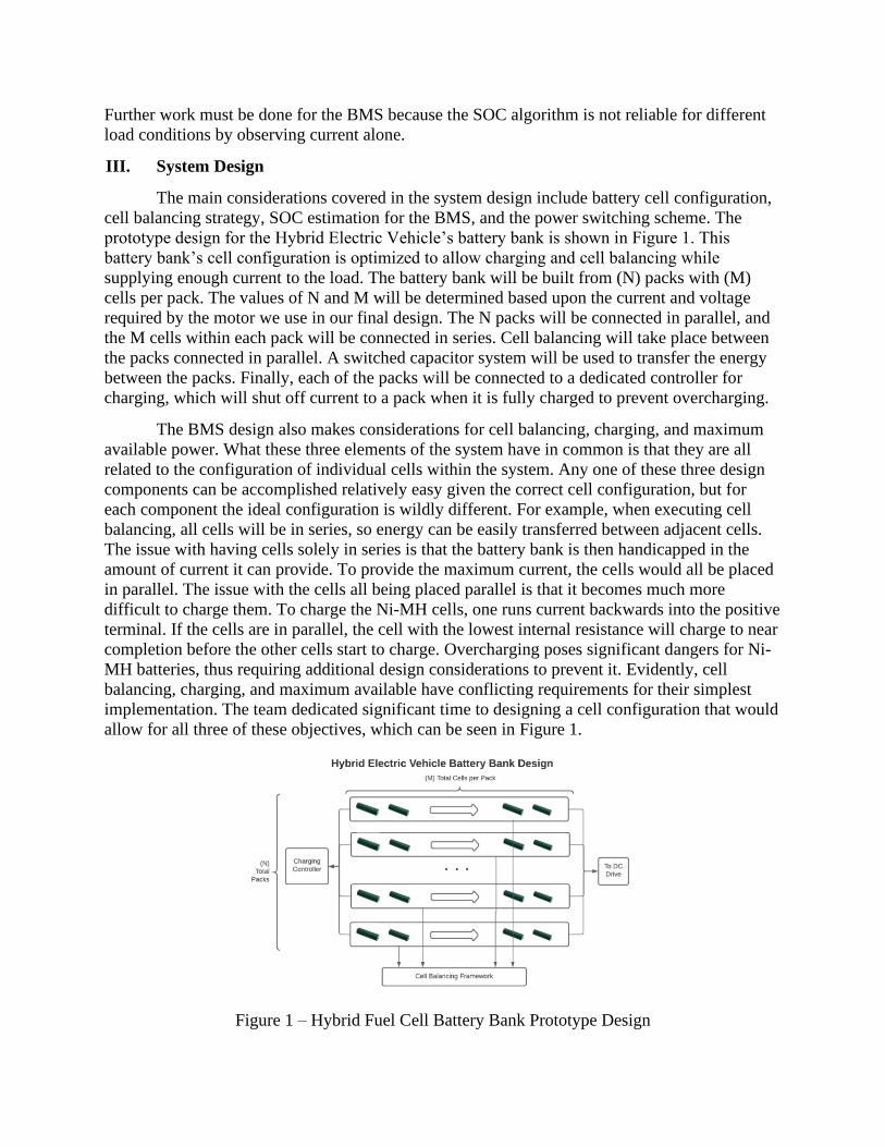
As Figure 3 shows, the capstone team’s goal was to use the hydrogen fuel cell as the
second power source of the system. This is not as simple a task as it may seem; the fuel cell
produces many times the power needed to run the motors used, and outputs at 12 V. In order to
fit the motor with the fuel cell, the capstone group took two steps: implementing a 12 V to 5 V
DC-DC converter and calculating the hydrogen input flowrate required to produce the desired
amount of power. This calculation was made with documentation provided with the fuel cell;
specifically, the hydrogen input to power output scale shown in Figure 4 [8]. Knowing that the
group’s electrolyzer can produce a maximum of 300 mL/min continuously, the team derived that
this equates to roughly 36 W of power. This is much more than is needed, however, so the team
decided to run tests when the electrolyzer and fuel cell were operational in order to determine the
optimal supply power.
Figure 4 – Hydrogen Input VS Power Output
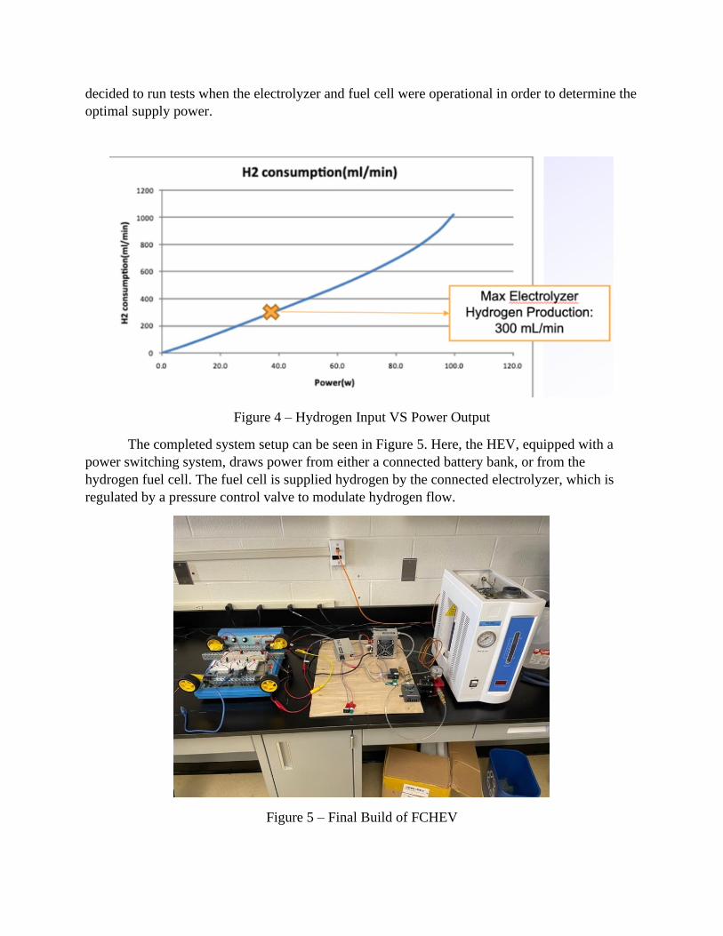
The completed system setup can be seen in Figure 5. Here, the HEV, equipped with a
power switching system, draws power from either a connected battery bank, or from the
hydrogen fuel cell. The fuel cell is supplied hydrogen by the connected electrolyzer, which is
regulated by a pressure control valve to modulate hydrogen flow.
Figure 5 – Final Build of FCHEV

The complete system design meets all objectives originally outlined for the team by the
USCG Marine Safety Center. The battery bank design allows for optimal charging and cell
balancing, while also fulfilling load requirements. Additionally, the BMS will be able to estimate
remaining battery capacity and cell health through SOC and SOH calculations. Lastly, the power
switching scheme allows for a hybrid system by switching between power supplies based upon
user defined conditions.
IV. Results
The group tested the battery-powered vehicle by running multiple discharge tests with
three batteries in series achieving an open-circuit voltage of 3.9 V. The purpose of the test was to
understand how the battery discharged over time at different load conditions and use this
information to develop the SOC and SOH algorithms for the BMS. The load attached was either
two or four motors in parallel, along with a variable resistor in parallel to achieve different
current discharge conditions of 190 mA, 440 mA, 560 mA, and 760 mA.
For data acquisition both the current and voltage sensors successfully interfaced with the
desktop through MATLAB. Two filters were used on the data to clean through the noisy
measurements. A moving mean filter was used to clean the voltage data, which a moving median
filter cleaned the current data. Both filters worked alongside MATLAB’s filloutliers function
which replaces outlier data with the previous value within certain thresholds. The testing
configuration and the results of the discharge tests is shown in Figures 6 and 7, respectively.
Figure 6 – Design Configuration for battery discharge tests with four motors and three batteries

Figure 7 - Discharging Performance at Terminal Voltage for Multiple Current Conditions
The results of the battery discharge tests were used to determine the system's voltage cut-
off point for SOC estimation. As mentioned earlier, the CC method to estimate SOC requires a
specific voltage value that represents when the battery pack is completely drained. This cut-off
point was found from the battery discharge tests. As shown in the Figure 7, the terminal voltage
will change depending on the load because of the internal resistance of the battery pack.
However, all these conditions face a considerable drop at the point of 2.5 V. This value was
therefore determined to be the voltage cut-off point for the algorithm to estimate SOC. It is
necessary for the system to stop receiving power at this point because it is unhealthy for battery
life to drop completely to 0 V.
After determining this value from the experimental results, the enhanced CC method
could be evaluated in Simulink to estimate SOC [5]. The model shows how the enhanced CC
method was implemented under discharging conditions only in Figures 8 and 9.
Figure 8 – Simulink Enhanced CC Algorithm Voltage Cut-off
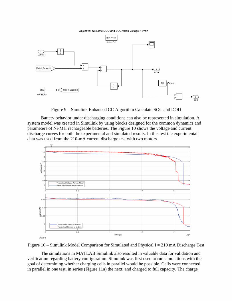
Figure 9 – Simulink Enhanced CC Algorithm Calculate SOC and DOD
Battery behavior under discharging conditions can also be represented in simulation. A
system model was created in Simulink by using blocks designed for the common dynamics and
parameters of Ni-MH rechargeable batteries. The Figure 10 shows the voltage and current
discharge curves for both the experimental and simulated results. In this test the experimental
data was used from the 210-mA current discharge test with two motors.
Figure 10 – Simulink Model Comparison for Simulated and Physical I = 210 mA Discharge Test
The simulations in MATLAB Simulink also resulted in valuable data for validation and
verification regarding battery configuration. Simulink was first used to run simulations with the
goal of determining whether charging cells in parallel would be possible. Cells were connected
in parallel in one test, in series (Figure 11a) the next, and charged to full capacity. The charge

curves for each simulation are shown in Figure 11. As shown in the figure, when charged in
parallel (Figure 11b), wildly different rates of charge occurred between cells. This was due to
differences in internal resistance of the cells causing different currents to flow through each cell.
When charged in series each cell charged at nearly the same rate. This is because when in series,
the current going through each cell is the same.
Figure 11a
Figure 11b
Figure 11 – Comparative Analysis of Charging Ni-MH Cells in Series, 11a, or Parallel, 11b
The data from this simulation is determining the optimal configuration for the cells in the
battery bank, shown in Figure 1, and allows for educated design choices to be later implemented
in Simulink and physical modelling.
Finally, the team was able to realize their power switching system design. This system
uses MOSFETS connected to an Arduino microcontroller to turn on and turn off the power
supply from two battery banks. This infrastructure will be used in conjunction with the SOC
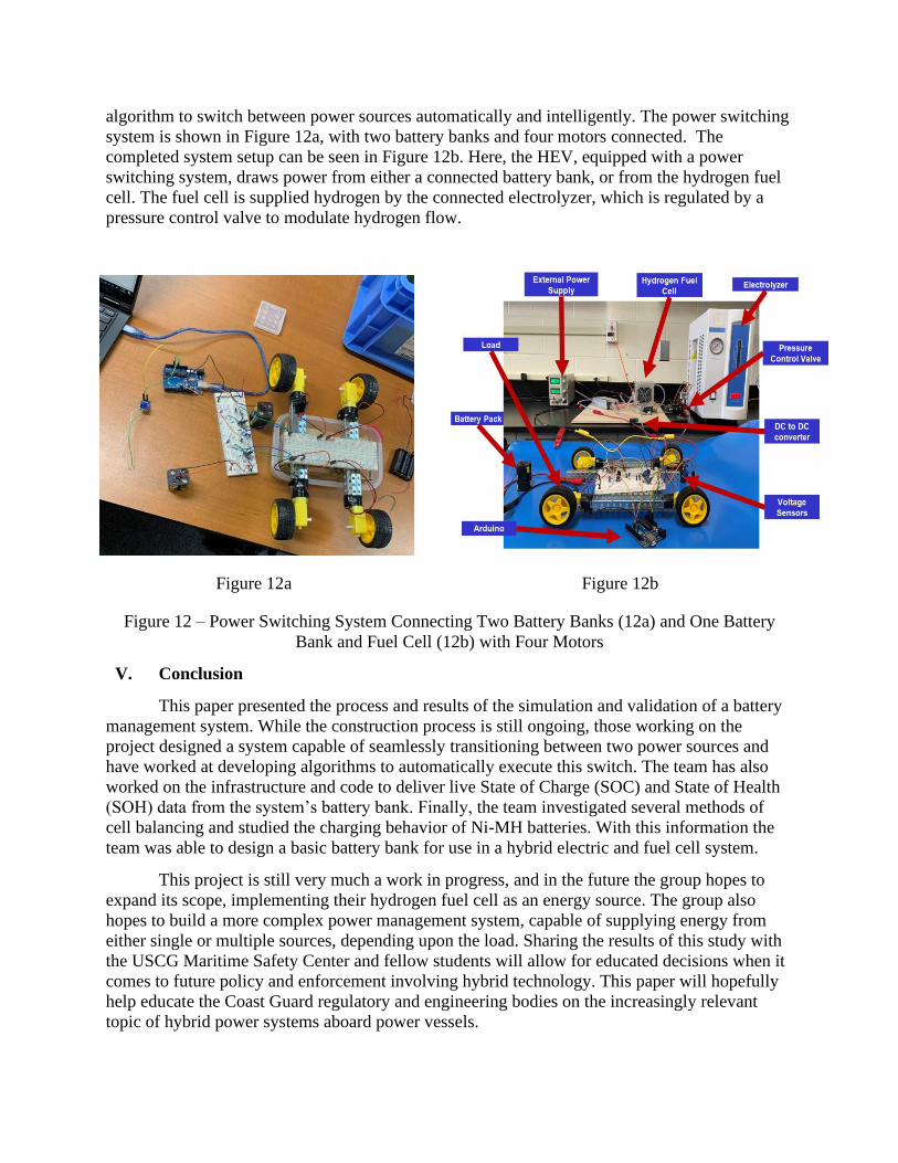
algorithm to switch between power sources automatically and intelligently. The power switching
system is shown in Figure 12a, with two battery banks and four motors connected. The
completed system setup can be seen in Figure 12b. Here, the HEV, equipped with a power
switching system, draws power from either a connected battery bank, or from the hydrogen fuel
cell. The fuel cell is supplied hydrogen by the connected electrolyzer, which is regulated by a
pressure control valve to modulate hydrogen flow.
Figure 12a Figure 12b
Figure 12 – Power Switching System Connecting Two Battery Banks (12a) and One Battery
Bank and Fuel Cell (12b) with Four Motors
V. Conclusion
This paper presented the process and results of the simulation and validation of a battery
management system. While the construction process is still ongoing, those working on the
project designed a system capable of seamlessly transitioning between two power sources and
have worked at developing algorithms to automatically execute this switch. The team has also
worked on the infrastructure and code to deliver live State of Charge (SOC) and State of Health
(SOH) data from the system’s battery bank. Finally, the team investigated several methods of
cell balancing and studied the charging behavior of Ni-MH batteries. With this information the
team was able to design a basic battery bank for use in a hybrid electric and fuel cell system.
This project is still very much a work in progress, and in the future the group hopes to
expand its scope, implementing their hydrogen fuel cell as an energy source. The group also
hopes to build a more complex power management system, capable of supplying energy from
either single or multiple sources, depending upon the load. Sharing the results of this study with
the USCG Maritime Safety Center and fellow students will allow for educated decisions when it
comes to future policy and enforcement involving hybrid technology. This paper will hopefully
help educate the Coast Guard regulatory and engineering bodies on the increasingly relevant
topic of hybrid power systems aboard power vessels.
VI. Students Outcome
This project, along with the two-semester Electrical Engineering Capstone class, provides
an excellent source to evaluate the student learning outcomes of the Electrical Engineering
curriculum at the U.S. Coast Guard Academy. As previously noted, the study of hydrogen fuel
cell technology and electric propulsion is extremely relevant to the U.S. Coast Guard, and the
global community. This project gave the students an opportunity to work collaboratively as a
team to accomplish a complex engineering task and to present their results to a mixed audience
of students, academics, and stakeholders.
This project provided multiple excellent opportunities for the team to enhance their
knowledge of battery and power systems and to implement the knowledge gained throughout
their undergraduate study. The development of a battery management system also involved
researching and acquiring new knowledge on battery technologies which was not included in
prior curriculum. The team was required to design experiments to test their theories, collect and
analyze the data, and improve the design of their system.
References
[1] Baccouche, A. Mlayah, S. Jemmali, B. Manai and N. Essoukri Ben Amara, "Implementation
of a Coulomb counting algorithm for SOC estimation of Li-Ion battery for multimedia
applications," 2015 IEEE 12th International Multi-Conference on Systems, Signals &
Devices (SSD15), Mahdia, 2015, pp. 1-6. doi: 10.1109/SSD.2015.7348255
[2] Corporation., Toyota Motor. “Toyota Develops Fuel Cell System for Maritime Applications:
Corporate: Global Newsroom.” Toyota Motor Corporation Official Global Website, 3 Feb.
2020, global.toyota/en/newsroom/corporate/31321325.html.
[3] B. Yildirim, M. Elgendy, A. Smith and V. Pickert, "Evaluation and Comparison of Battery
Cell Balancing Methods," 2019 IEEE PES Innovative Smart Grid Technologies Europe
(ISGT-Europe), Bucharest, Romania, 2019, pp. 1-5, doi:
10.1109/ISGTEurope.2019.8905588.
[4] Jensen, Sara. “Hydrogen Fuel and Fuel Cell Development.” Highway, 18 Sept. 2019,
www.oemoffhighway.com/engines/fuels-fluids/article/20866766/hydrogen-fuel-and-fuel-
cell-development.
[5] Ng, Kong Soon, et al. "Enhanced coulomb counting method for estimating state-of-charge
and state-of-health of lithium-ion batteries." Applied energy 86.9 (2009): 1506-1511.
[6] M. Khalid, S. S. Sheikh, A. K. Janjua and H. A. Khalid, "Performance Validation of Electric
Vehicle’s Battery Management System under state of charge estimation for lithium-ion
Battery," 2018 International Conference on Computing, Electronic and Electrical
Engineering (ICE Cube), Quetta, 2018, pp. 1-5, doi: 10.1109/ICECUBE.2018.8610969.
[7] C. Qian et al., "Smooth Control Strategy for Fuel Cell-Battery Power System," 2019 IEEE
3rd Conference on Energy Internet and Energy System Integration (EI2), Changsha, China,
2019, pp. 1139-1143, doi: 10.1109/EI247390.2019.9061818.
[8] H-100 Fuel Cell Stack User Manual_FCS-C100_V2.1_EN, Updated, Dec 2014, horizon-
pem-fuel-cell-h-100-manual.pdf (fuelcellstore.com)