Embed Size (px)
Citation preview
1
A Fully Functional Fired Heater Simulator
For
Teaching Safe Efficient Heater Operation
Richard Martin
Aztec Engineering LLC
www.aztecengineering.com
Table of Contents
Introduction...................................................................................................................1
Aztec Engineering Trainer © Process Heater Simulator .............................................2
Process Heater and Simulator Operation Examples....................................................2
Excess air and Efficiency.............................................................................................2
Combustion .................................................................................................................4
Weather Conditions .....................................................................................................7
Trainer © Fired Heater Simulator Flexibility ..............................................................8
Trainer © Fired Heater Simulator and PowerPoint Presentations ...........................10
Conclusions ..................................................................................................................11
Introduction
Process heaters are used in the refining and chemical industries to heat fluids. The heaters
have a radiant section and a convection section each with tubes through which the process
fluid flows. There are many heater configurations operating with a variety of different
operating conditions. The operator is responsible for safe efficient operation of the heater to
achieve the required fluid outlet temperature with a minimum of undesirable emissions.
The increased cost of energy and stringent environmental regulations have increased the
difficulty of safely operating a fired process heater in a refinery or chemical plant. The
energy cost has created an emphasis on operating with the minimum possible excess air and
the stringent environmental regulations have forced the development of low NOx burners that
have longer flame lengths than conventional burners and reduced burner stability for low
excess air operation. The less defined flames of the low NOx burners may often lead to flame
impingement on the process tubes and high tube metal temperatures. Instability of the burners
at low excess air levels creates numerous safety issues.
This increased operating difficulty means that traditional combustion site operator training is
no longer acceptable. It is no longer acceptable for operators to set an excess air level for the
heater that ensures that most changes in operating parameters, either process or atmospheric,
will not upset the heater operation.
In a sense, there are two separate process heater systems, the combustion system and the
process system. The process system has a set of inlet conditions that can vary and a required
set of outlet conditions that are fixed for a given state of operation. The operator must
achieve the required process outlet conditions by controlling the combustion system. The
controls available to the operator are the stack damper (ID blower flow control for induced
2
draft systems) used for controlling the heater draft, burner inlet damper or register (FD
blower flow control for forced draft systems) used for controlling the quantity of combustion
air, and the fuel flow control valve. Usually the fuel flow is automatically controlled, but the
burner register(s) and stack damper, in the majority of cases is manually controlled.
Typically the operator training is separated into process training and combustion training.
The operators usually get very detailed specific training for the process system, but this
training is independent from the combustion training. The combustion training usually
consists of a presentation, possibly by a burner vendor, who discusses general burner
operation, aspects of burner design and start up and shut down procedures. Usually the
dynamics of the heater/burner system during operating changes are not discussed any detail
because of the difficulty of presenting the material and easily understandable manner. In
other words, the operating challenges that can occur during 99% of the operating time are not
addressed in any specific detail. When the situations are addressed, it is usually a static
(PowerPoint) demonstration that cannot convey the complete dynamics of the heater/burner
system.
Now there is a combustion side process heater operator training program that permits the
student operator to "see" almost every possible change in operating conditions and allow him
to actually control a simulated heater to resolve any operational difficulties in a safe and
efficient manner. Several PowerPoint presentation modules are supplied with the simulator to
provide necessary background instructional materials.
Aztec Engineering Trainer © Process Heater Simulator
The Aztec Engineering Trainer © Process Heater Simulator functions exactly like a fired
process heater. When one control device is adjusted all of the heater operating parameters
change accordingly. Other heater "simulators" that are available are really "calculators". For
example, if a new value of draft is entered a new airflow is calculated. However, the change
in heat transfer to the process that results from different flame lengths, combustion product
emissivity and combustion product temperature is not reflected in the new calculated
parameters.
The draft for an actual operating natural draft heater is changed by adjusting the stack
damper. If the draft is reduced by closing the stack damper, the airflow to the burner is
reduced, which decreases the excess air, shifts heat transfer from the convection section to
the radiant section, reduces the stack temperature and the flow rate of combustion products
from the stack causing an increase in efficiency which in turn increases the process outlet
temperature unless the fuel flow is reduced. If the above values were simply calculated based
on a draft “input” they are incorrect because there is a resulting decrease in pressure loss
across the convection section that leads to a slight increase in draft at the burner which means
all of the above values must be recalculated.
Process Heater and Simulator Operation Examples
Excess air and Efficiency
Most operators understand that it is necessary to operate the heaters with the minimum
possible excess air to reduce fuel consumption and in some cases reduce the generation of
3
NOx. However, they do not necessarily understand how changing excess air affects the other
heater operating parameters. A fully functional true simulator can provide a memorable
demonstration of excess air control especially if the student operators are permitted to first
analyze the situation and then control the simulator. The following two screenshots provide
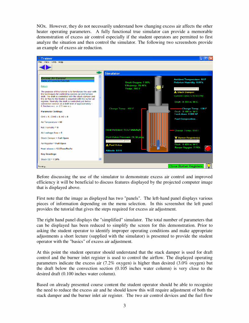
an example of excess air reduction.
Before discussing the use of the simulator to demonstrate excess air control and improved
efficiency it will be beneficial to discuss features displayed by the projected computer image
that is displayed above.
First note that the image as displayed has two "panels". The left-hand panel displays various
pieces of information depending on the menu selection. In this screenshot the left panel
provides the tutorial that gives the steps required for excess air adjustment.
The right hand panel displays the "simplified" simulator. The total number of parameters that
can be displayed has been reduced to simplify the screen for this demonstration. Prior to
asking the student operator to identify improper operating conditions and make appropriate
adjustments a short lecture (supplied with the simulator) is presented to provide the student
operator with the "basics" of excess air adjustment.
At this point the student operator should understand that the stack damper is used for draft
control and the burner inlet register is used to control the airflow. The displayed operating
parameters indicate the excess air (7.2% oxygen) is higher than desired (3.0% oxygen) but
the draft below the convection section (0.105 inches water column) is very close to the
desired draft (0.100 inches water column).
Based on already presented course content the student operator should be able to recognize
the need to reduce the excess air and he should know this will require adjustment of both the
stack damper and the burner inlet air register. The two air control devices and the fuel flow
4
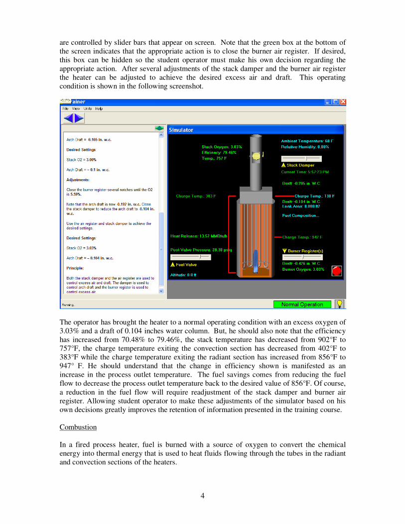
are controlled by slider bars that appear on screen. Note that the green box at the bottom of
the screen indicates that the appropriate action is to close the burner air register. If desired,
this box can be hidden so the student operator must make his own decision regarding the
appropriate action. After several adjustments of the stack damper and the burner air register
the heater can be adjusted to achieve the desired excess air and draft. This operating
condition is shown in the following screenshot.
The operator has brought the heater to a normal operating condition with an excess oxygen of
3.03% and a draft of 0.104 inches water column. But, he should also note that the efficiency
has increased from 70.48% to 79.46%, the stack temperature has decreased from 902°F to
757°F, the charge temperature exiting the convection section has decreased from 402°F to
383°F while the charge temperature exiting the radiant section has increased from 856°F to
947° F. He should understand that the change in efficiency shown is manifested as an
increase in the process outlet temperature. The fuel savings comes from reducing the fuel
flow to decrease the process outlet temperature back to the desired value of 856°F. Of course,
a reduction in the fuel flow will require readjustment of the stack damper and burner air
register. Allowing student operator to make these adjustments of the simulator based on his
own decisions greatly improves the retention of information presented in the training course.
Combustion
In a fired process heater, fuel is burned with a source of oxygen to convert the chemical
energy into thermal energy that is used to heat fluids flowing through the tubes in the radiant
and convection sections of the heaters.
5
In refineries, and in some cases, in chemical plants the composition of the fuel can change
radically. In many cases, the fuels are mixtures of waste gases generated during the
production of useful products. These waste gases can consist of many different components.
Some of the more common components are methane (CH4), propane (C3H8), and hydrogen
(H2). Further complicating the situation is the composition of the fuel can change
significantly during normal heater operation depending on the operating conditions in other
parts of the plant and in some cases the composition can change very rapidly. The operator
needs to understand how the change in fuel composition affects the operation of the heater.
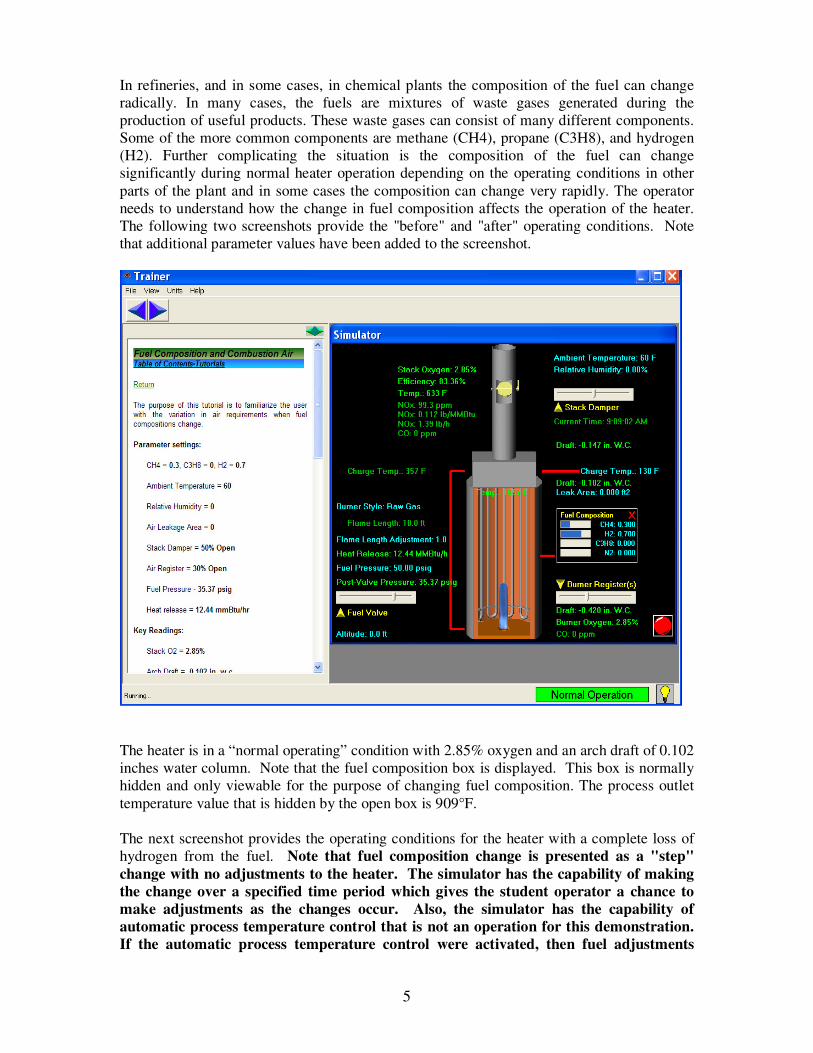
The following two screenshots provide the "before" and "after" operating conditions. Note
that additional parameter values have been added to the screenshot.
The heater is in a “normal operating” condition with 2.85% oxygen and an arch draft of 0.102
inches water column. Note that the fuel composition box is displayed. This box is normally
hidden and only viewable for the purpose of changing fuel composition. The process outlet
temperature value that is hidden by the open box is 909°F.
The next screenshot provides the operating conditions for the heater with a complete loss of
hydrogen from the fuel. Note that fuel composition change is presented as a "step"
change with no adjustments to the heater. The simulator has the capability of making
the change over a specified time period which gives the student operator a chance to
make adjustments as the changes occur. Also, the simulator has the capability of
automatic process temperature control that is not an operation for this demonstration.
If the automatic process temperature control were activated, then fuel adjustments
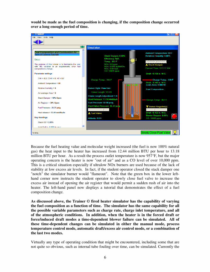
6
would be made as the fuel composition is changing, if the composition change occurred
over a long enough period of time.
Because the fuel heating value and molecular weight increased (the fuel is now 100% natural
gas) the heat input to the heater has increased from 12.44 million BTU per hour to 13.18
million BTU per hour. As a result the process outlet temperature is now 957°F, but the major
operating concern is the heater is now "out of air" and as a CO level of over 10,000 ppm.
This is a critical situation especially if ultralow NOx burners are used because of the lack of
stability at low excess air levels. In fact, if the student operator closed the stack damper one
"notch" the simulator burner would "flameout". Note that the green box in the lower left-
hand corner now instructs the student operator to slowly close fuel valve to increase the
excess air instead of opening the air register that would permit a sudden rush of air into the
heater. The left-hand panel now displays a tutorial that demonstrates the effect of a fuel
composition change.
As discussed above, the Trainer © fired heater simulator has the capability of varying
the fuel composition as a function of time. The simulator has the same capability for all
the possible variable parameters such as charge rate, charge inlet temperature, and all
of the atmospheric conditions. In addition, when the heater is in the forced draft or
force/induced draft modes a time-dependent blower failure can be simulated. All of
these time-dependent changes can be simulated in either the manual mode, process
temperature control mode, automatic draft/excess air control mode, or a combination of
the last two modes.
Virtually any type of operating condition that might be encountered, including some that are
not quite so obvious, such as internal tube fouling over time, can be simulated. Currently the
7
simulator includes approximately 20 tutorials for various situations. In addition, custom
tutorials can easily be added. One more example that is weather-related will be discussed.
Weather Conditions
Changes in atmospheric conditions can affect the operation of natural draft process heaters
and in some cases the atmospheric conditions can affect the safety of the operation.
The heater is in a normal operating condition with an ambient temperature of 60°F and a
relative humidity of 0%. It is a very dry relatively cool morning. As the day progresses, the
temperature increases and there is a sudden thunderstorm in mid-afternoon. The heater is
operating in a manual mode and essentially no adjustments have been made as the day
progressed. Note that the left panel now has a tutorial that is used to illustrate a change
combustion air temperature.
8
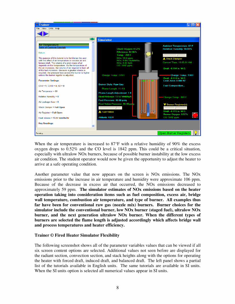
When the air temperature is increased to 87°F with a relative humidity of 90% the excess
oxygen drops to 0.52% and the CO level is 1842 ppm. This could be a critical situation,
especially with ultralow NOx burners, because of possible burner instability at the low excess
air condition. The student operator would now be given the opportunity to adjust the heater to
arrive at a safe operating condition.
Another parameter value that now appears on the screen is NOx emissions. The NOx
emissions prior to the increase in air temperature and humidity were approximate 106 ppm.
Because of the decrease in excess air that occurred, the NOx emissions decreased to
approximately 59 ppm. The simulator estimates of NOx emissions based on the heater
operation taking into consideration items such as fuel composition, excess air, bridge
wall temperature, combustion air temperature, and type of burner. All examples thus
far have been for conventional raw gas (nozzle mix) burners. Burner choices for the
simulator include the conventional burner, low NOx burner (staged fuel), ultralow NOx
burner, and the next generation ultralow NOx burner. When the different types of
burners are selected the flame length is adjusted accordingly which affects bridge wall
and process temperatures and heater efficiency.
Trainer © Fired Heater Simulator Flexibility
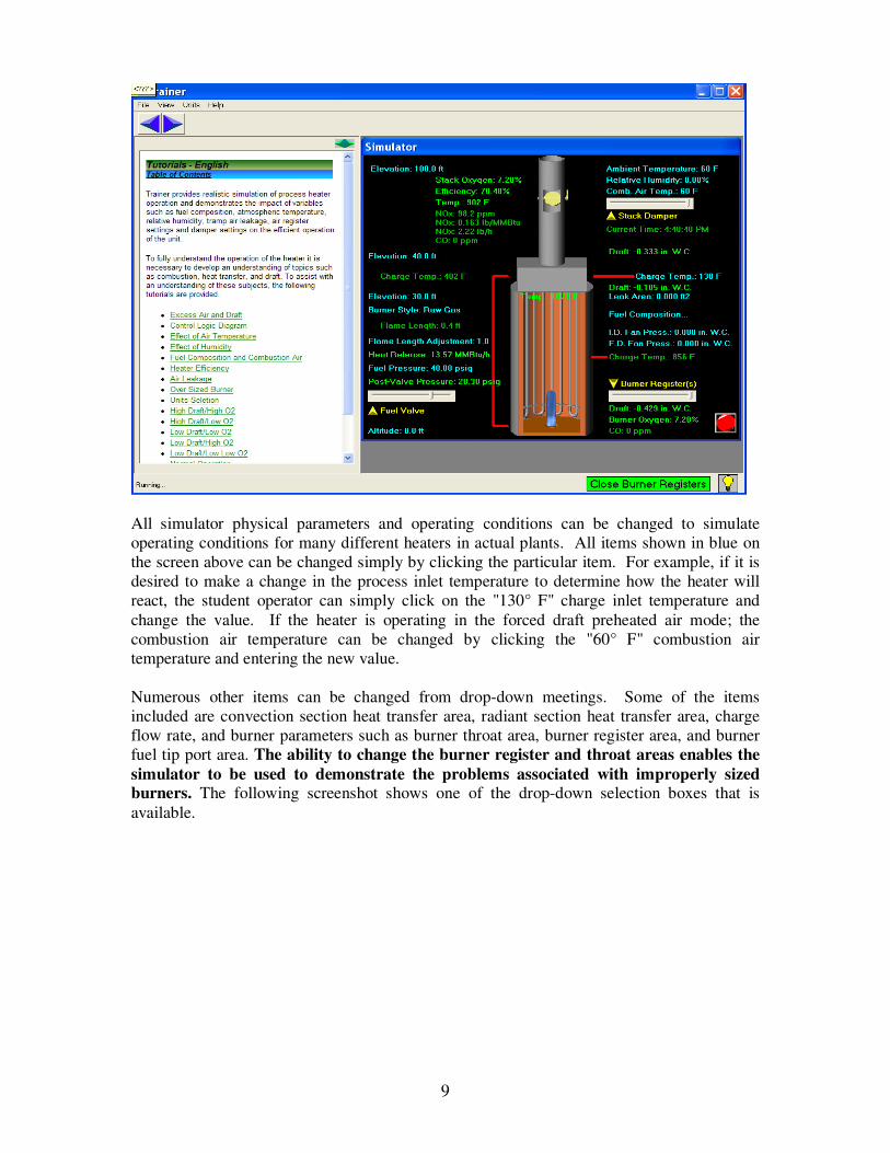
The following screenshot shows all of the parameter variables values that can be viewed if all
six screen content options are selected. Additional values not seen before are displayed for
the radiant section, convection section, and stack heights along with the options for operating
the heater with forced draft, induced draft, and balanced draft. The left panel shows a partial
list of the tutorials available in English units. The same tutorials are available in SI units.
When the SI units option is selected all numerical values appear in SI units.
9
All simulator physical parameters and operating conditions can be changed to simulate
operating conditions for many different heaters in actual plants. All items shown in blue on
the screen above can be changed simply by clicking the particular item. For example, if it is
desired to make a change in the process inlet temperature to determine how the heater will
react, the student operator can simply click on the "130° F" charge inlet temperature and
change the value. If the heater is operating in the forced draft preheated air mode; the
combustion air temperature can be changed by clicking the "60° F" combustion air
temperature and entering the new value.
Numerous other items can be changed from drop-down meetings. Some of the items
included are convection section heat transfer area, radiant section heat transfer area, charge
flow rate, and burner parameters such as burner throat area, burner register area, and burner
fuel tip port area. The ability to change the burner register and throat areas enables the
simulator to be used to demonstrate the problems associated with improperly sized
burners. The following screenshot shows one of the drop-down selection boxes that is
available.
10
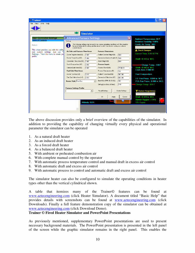
The above discussion provides only a brief overview of the capabilities of the simulator. In
addition to providing the capability of changing virtually every physical and operational
parameter the simulator can be operated
1. As a natural draft heater
2. As an induced draft heater
3. As a forced draft heater
4. As a balanced draft heater
5. With ambient or preheated combustion air
6. With complete manual control by the operator
7. With automatic process temperature control and manual draft in excess air control
8. With automatic draft and excess air control
9. With automatic process to control and automatic draft and excess air control
The simulator heater can also be configured to simulate the operating conditions in heater
types other than the vertical cylindrical shown.
A table that itemizes many of the Trainer© features can be found at
www.aztecengineering.com (click Heater Simulator). A document titled “Basic Help” that
provides details with screenshots can be found at www.aztecengineering.com (click
Downloads). Finally a full feature demonstration copy of the simulator can be obtained at
www.aztecengineering.com (click Download Demo).
Trainer © Fired Heater Simulator and PowerPoint Presentations
As previously mentioned, supplementary PowerPoint presentations are used to present
necessary background materials. The PowerPoint presentation is presented in the left panel
of the screen while the graphic simulator remains in the right panel. This enables the
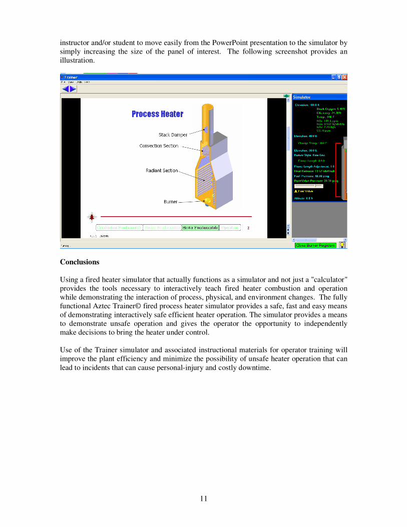
11
instructor and/or student to move easily from the PowerPoint presentation to the simulator by
simply increasing the size of the panel of interest. The following screenshot provides an
illustration.
Conclusions
Using a fired heater simulator that actually functions as a simulator and not just a "calculator"
provides the tools necessary to interactively teach fired heater combustion and operation
while demonstrating the interaction of process, physical, and environment changes. The fully
functional Aztec Trainer© fired process heater simulator provides a safe, fast and easy means
of demonstrating interactively safe efficient heater operation. The simulator provides a means
to demonstrate unsafe operation and gives the operator the opportunity to independently
make decisions to bring the heater under control.
Use of the Trainer simulator and associated instructional materials for operator training will
improve the plant efficiency and minimize the possibility of unsafe heater operation that can
lead to incidents that can cause personal-injury and costly downtime.