Embed Size (px)
Citation preview
Simultaneous Analog Placement and Routing with Current Flow and Current Density Considerations
H.C. Ou, H.C.C. Chien and Y.W. Chang
Electronics Engineering, NTU, Taiwan
DAC 2013
Outline
Introduction Problem Formulation The Enhanced B*-tree Representation Simultaneous Placement and Routing Experimental Results Conclusions
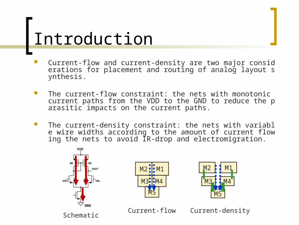
Introduction Current-flow and current-density are two major considerations for pla
cement and routing of analog layout synthesis.
The current-flow constraint: the nets with monotonic current paths from the VDD to the GND to reduce the parasitic impacts on the current paths.
The current-density constraint: the nets with variable wire widths according to the amount of current flowing the nets to avoid IR-drop and electromigration.
Schematic
M2 M1
M4M3
M5
M2 M1
M4M3
M5
Current-flow Current-density
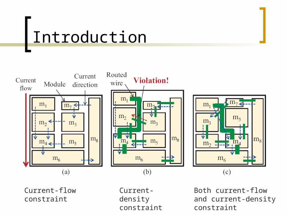
Introduction
Current-flow constraint Current-density constraint
Both current-flow and current-density constraint
Problem Formulation
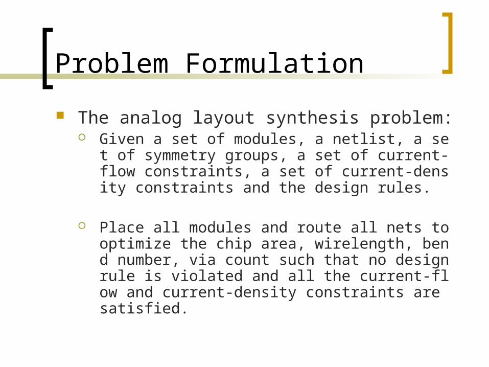
The analog layout synthesis problem: Given a set of modules, a netlist, a set of symme
try groups, a set of current-flow constraints, a set of current-density constraints and the design rules.
Place all modules and route all nets to optimize the chip area, wirelength, bend number, via count such that no design rule is violated and all the current-flow and current-density constraints are satisfied.
Review of Hierarchical and ASF-B*-tree
m1s
m2
m6’
m6
m2’m5
m7s m8
s
m4m3
b5
bS1
b3
b4
bS2
b2’
b1s
b6’
b7s
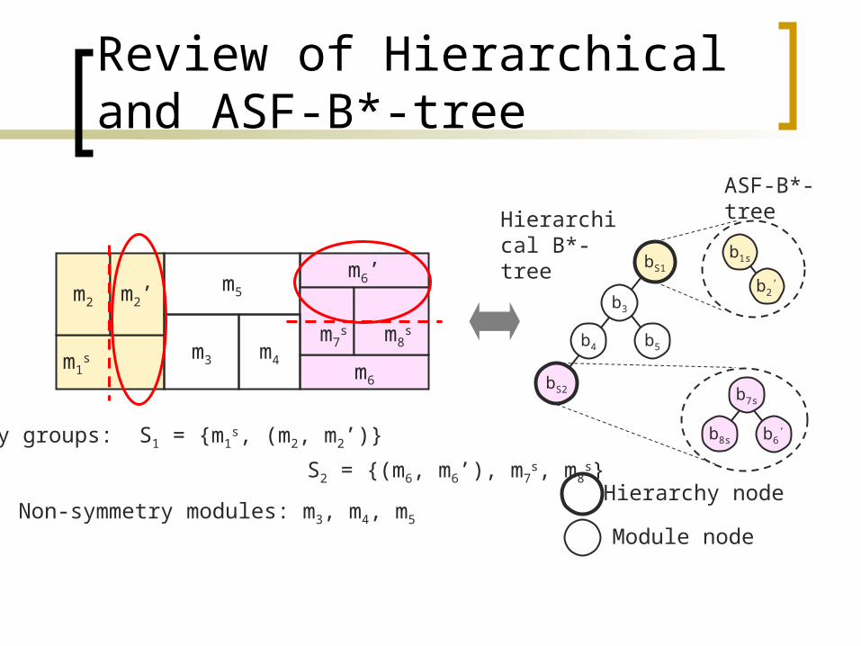
b8sSymmetry groups: S1 = {m1s, (m2, m2’)}
S2 = {(m6, m6’), m7s, m8
s}Hierarchy node
Module nodeNon-symmetry modules: m3, m4, m5
Hierarchical B*-tree
ASF-B*-tree
The Enhanced B*-tree Representation
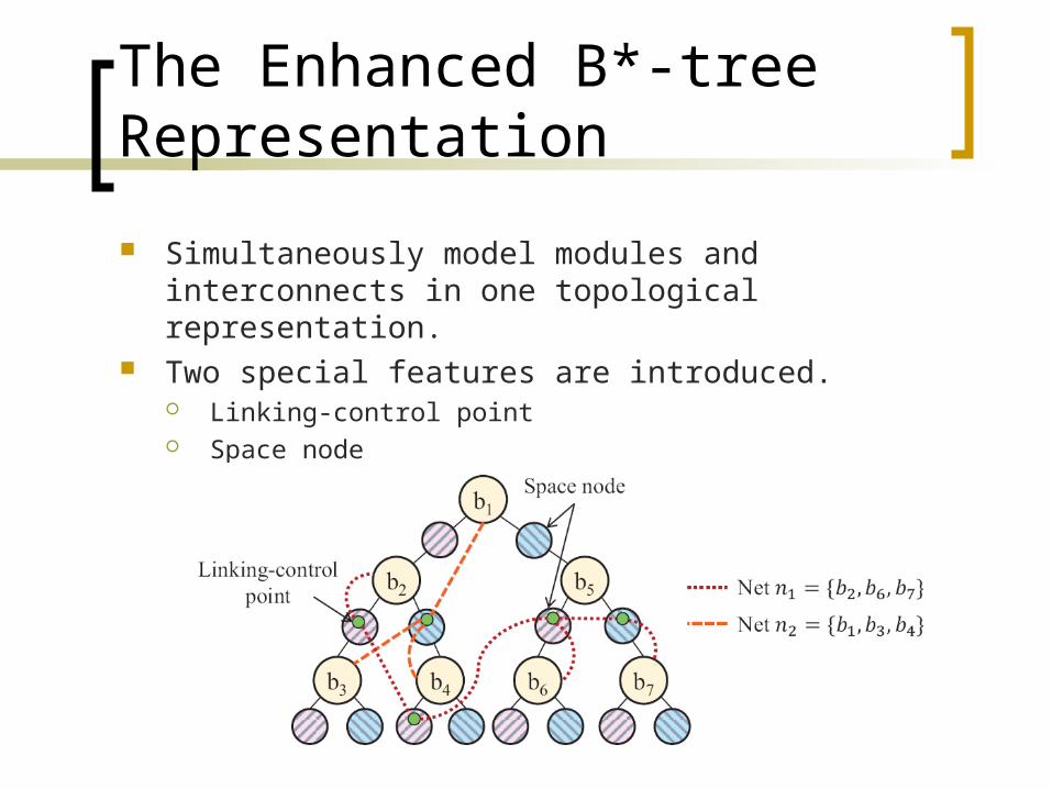
Simultaneously model modules and interconnects in one topological representation.
Two special features are introduced. Linking-control point Space node
Linking-control point
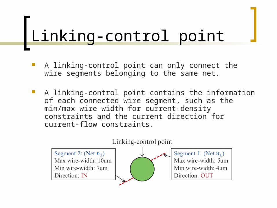
A linking-control point can only connect the wire segments belonging to the same net.
A linking-control point contains the information of each connected wire segment, such as the min/max wire width for current-density constraints and the current direction for current-flow constraints.
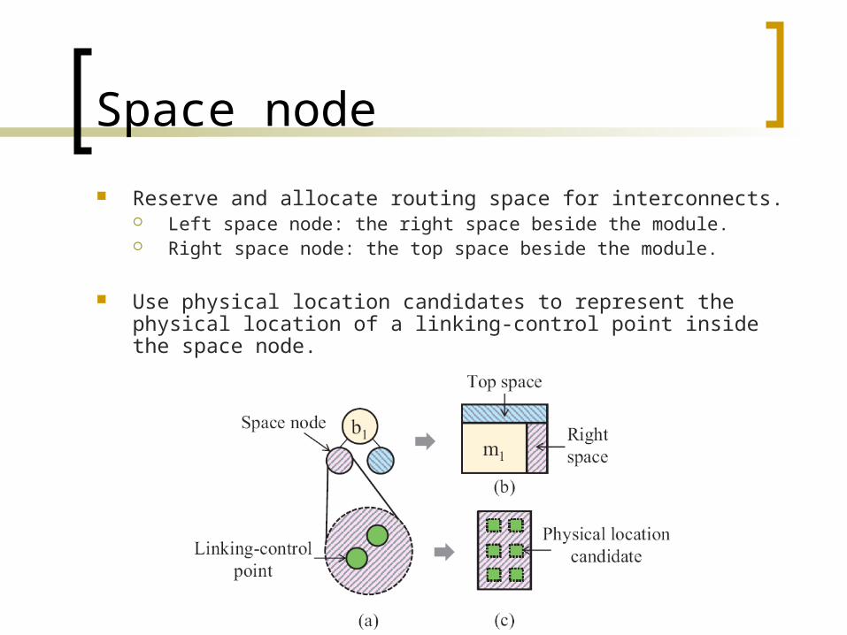
Space node
Reserve and allocate routing space for interconnects. Left space node: the right space beside the module. Right space node: the top space beside the module.
Use physical location candidates to represent the physical location of a linking-control point inside the space node.
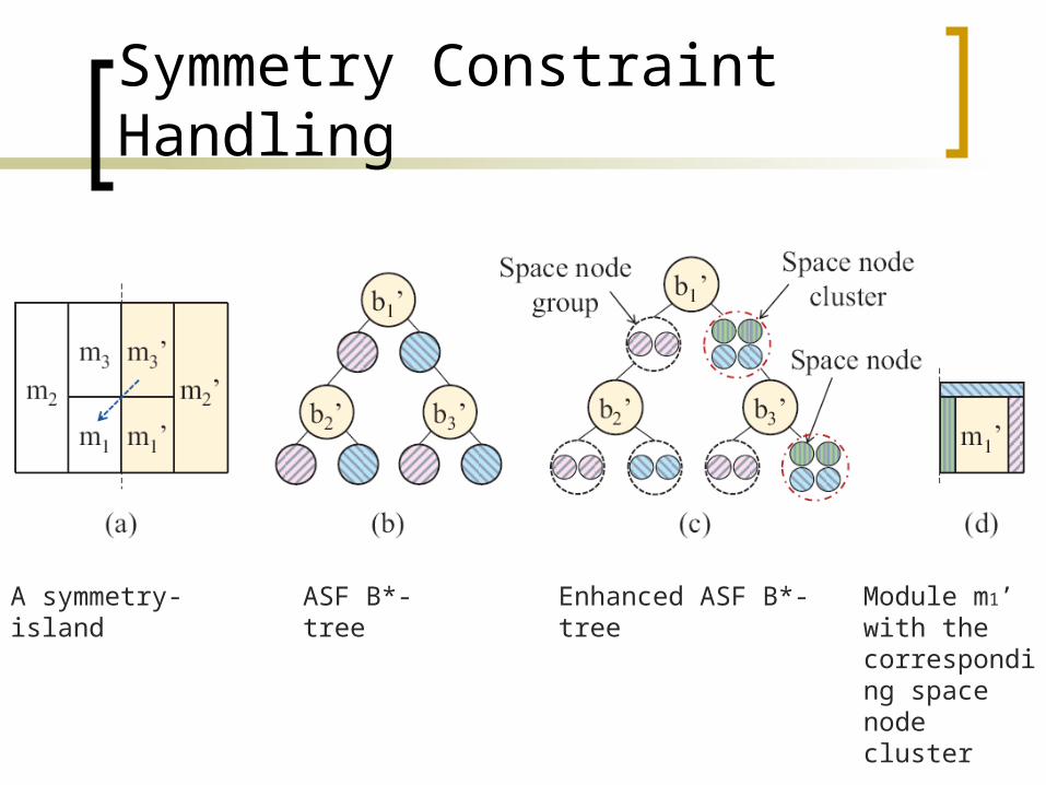
Symmetry Constraint Handling
A symmetry-island ASF B*-tree Enhanced ASF B*-tree Module m1’ with the corresponding space node cluster
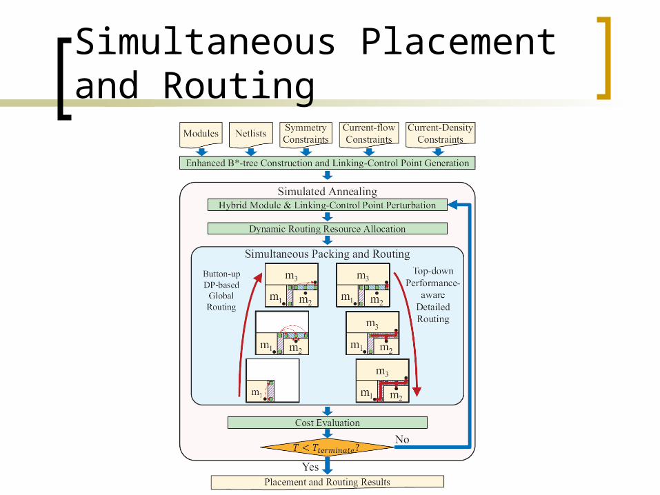
Simultaneous Placement and Routing
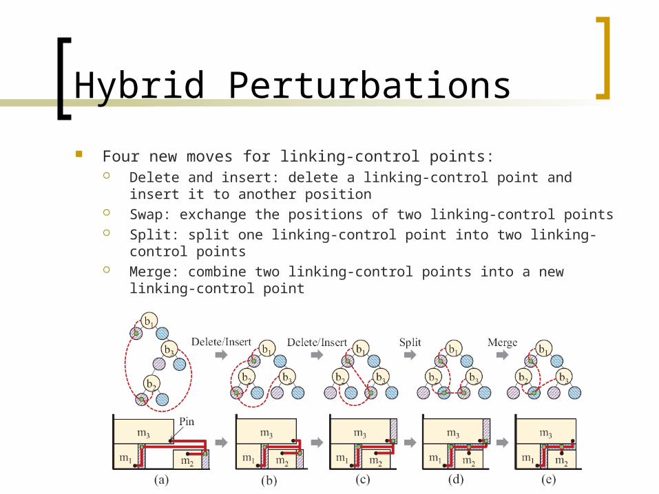
Hybrid Perturbations
Four new moves for linking-control points: Delete and insert: delete a linking-control point and insert it to
another position Swap: exchange the positions of two linking-control points Split: split one linking-control point into two linking-control points Merge: combine two linking-control points into a new linking-
control point
Dynamic Routing Resource Reservation and Allocation
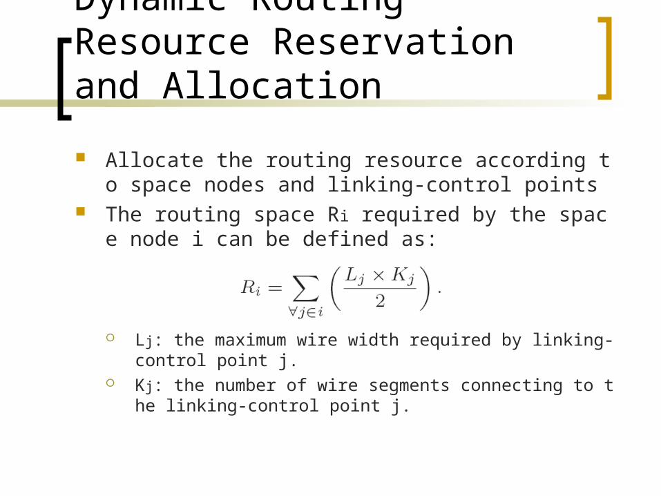
Allocate the routing resource according to space nodes and linking-control points
The routing space Ri required by the space node i can be defined as:
Lj: the maximum wire width required by linking-control point j.
Kj: the number of wire segments connecting to the linking-control point j.
Dynamic-Programming-Based Global Routing
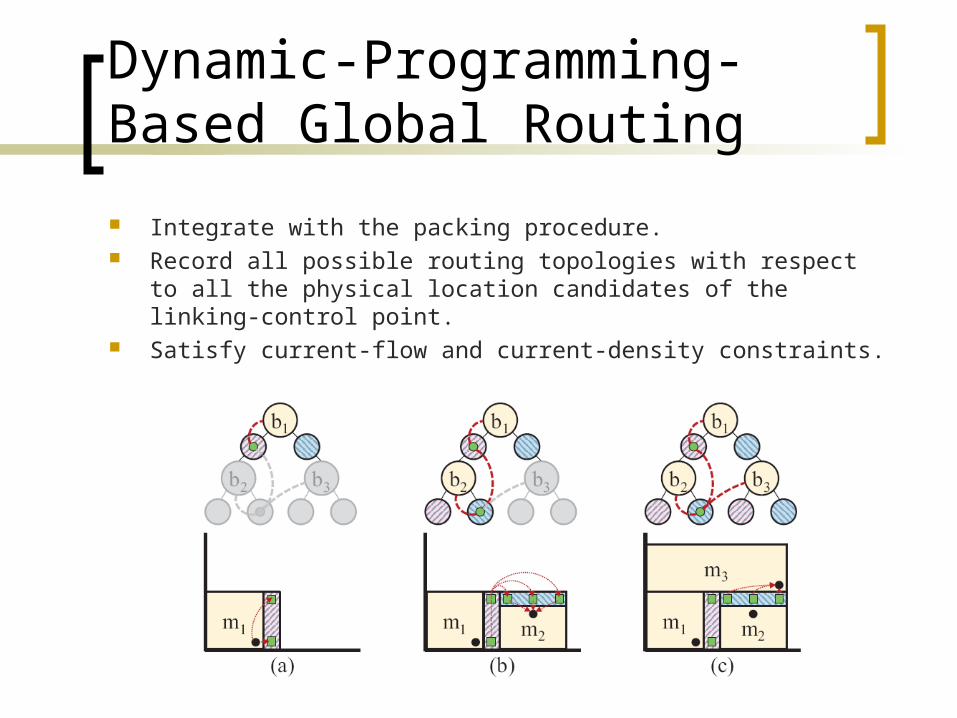
Integrate with the packing procedure. Record all possible routing topologies with respect to all the
physical location candidates of the linking-control point. Satisfy current-flow and current-density constraints.
Dynamic-Programming-Based Global Routing
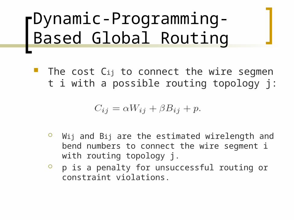
The cost Cij to connect the wire segment i with a possible routing topology j:
Wij and Bij are the estimated wirelength and bend numbers to connect the wire segment i with routing topology j.
p is a penalty for unsuccessful routing or constraint violations.
Performance-Aware Detailed Routing
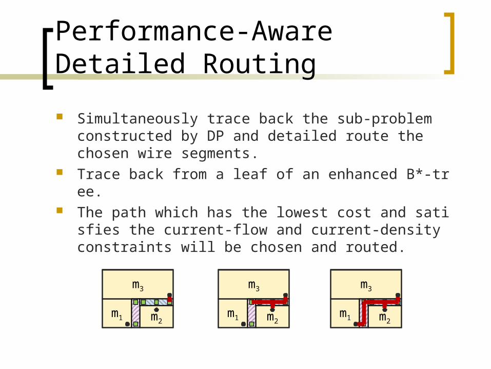
Simultaneously trace back the sub-problem constructed by DP and detailed route the chosen wire segments.
Trace back from a leaf of an enhanced B*-tree. The path which has the lowest cost and satisfies the
current-flow and current-density constraints will be chosen and routed.
m1 m2
m3
m1 m2
m3
m1 m2
m3
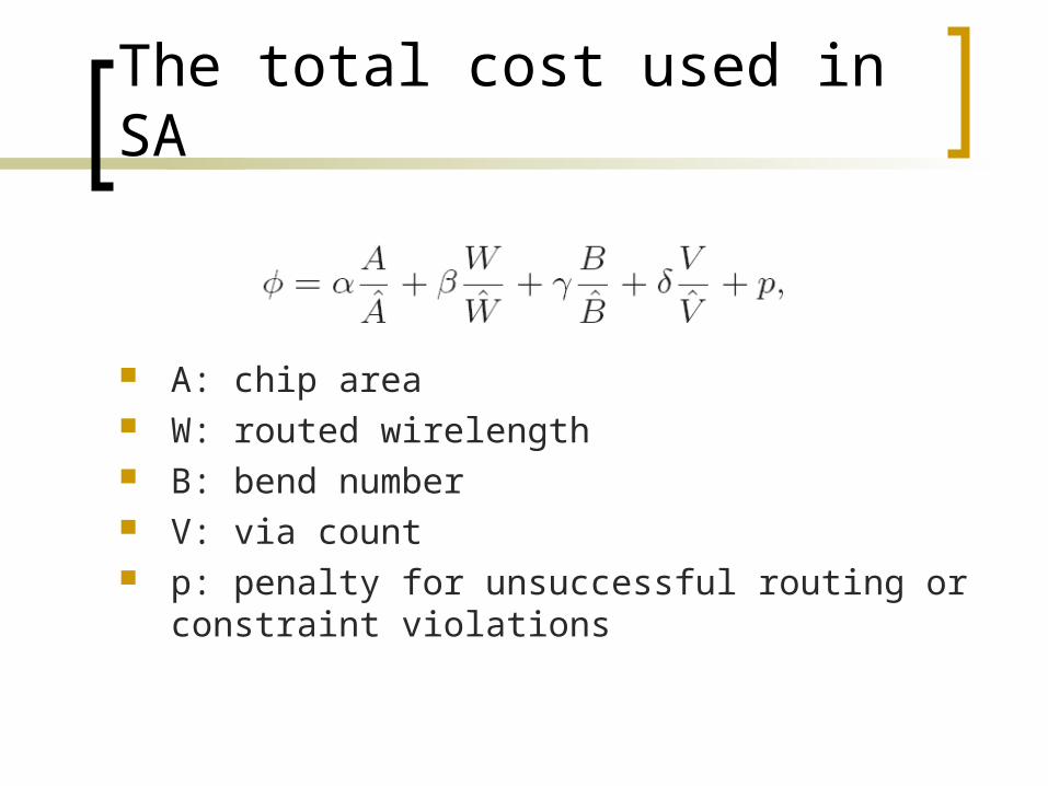
The total cost used in SA
A: chip area W: routed wirelength B: bend number V: via count p: penalty for unsuccessful routing or constraint viol
ations
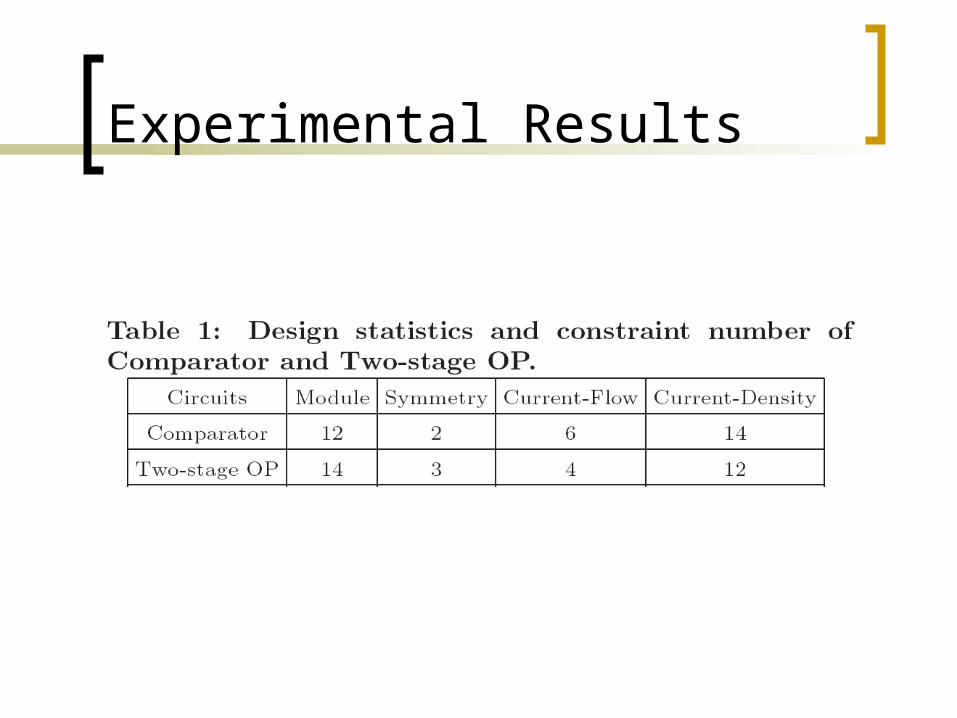
Experimental Results
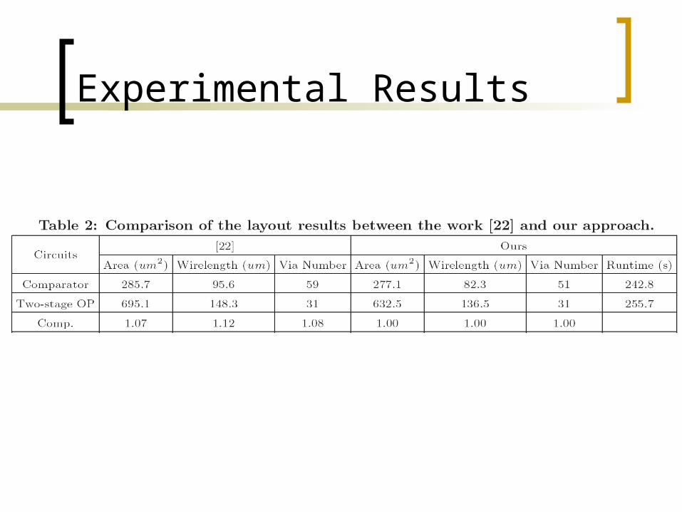
Experimental Results
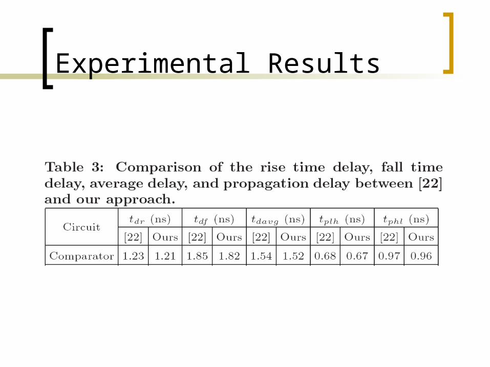
Experimental Results
Conclusions
This paper proposed a simultaneous placement and routing algorithm with current-flow and current density constraints for analog circuit designs.
Experimental results show that the proposed approach can obtain better layout results and satisfy all specified constraints.


![Nuclear Physics in Taiwan – Highlights and Updates · 2019. 7. 8. · Nuclear Charge Radius with laser spectroscopy & Muonic Atoms @ PSI [Y.W. Liu, NTHU] Neutrino Oscillations @](https://img.pdfslide.net/doc/110x75/601af6e82d8dc3393f04f8a7/nuclear-physics-in-taiwan-a-highlights-and-updates-2019-7-8-nuclear-charge.jpg)