Embed Size (px)
Citation preview

s
SINAMICSG120G120
Power Module
PM250
Hardware Installation Manual · Edition 11/2006


Introduction 1
Safety notes 2
Description 3
Installing/Mounting 4
Operation (hardware) 5
Technical data 6
Dimensional drawings 7
Spare parts/Accessories 8
Appendix A
List of abbreviations B
SINAMICS
SINAMICS G120 Power Modules PM250
Hardware Installation Manual
11/2006 A5E01003502AB
Edition 11/2006

Safety Guidelines This manual contains notices you have to observe in order to ensure your personal safety, as well as to prevent damage to property. The notices referring to your personal safety are highlighted in the manual by a safety alert symbol, notices referring only to property damage have no safety alert symbol. These notices shown below are graded according to the degree of danger.
Danger
indicates that death or severe personal injury will result if proper precautions are not taken.
Warning
indicates that death or severe personal injury may result if proper precautions are not taken.
Caution
with a safety alert symbol, indicates that minor personal injury can result if proper precautions are not taken.
Caution
without a safety alert symbol, indicates that property damage can result if proper precautions are not taken.
Notice
indicates that an unintended result or situation can occur if the corresponding information is not taken into account.
If more than one degree of danger is present, the warning notice representing the highest degree of danger will be used. A notice warning of injury to persons with a safety alert symbol may also include a warning relating to property damage.
Qualified Personnel The device/system may only be set up and used in conjunction with this documentation. Commissioning and operation of a device/system may only be performed by qualified personnel. Within the context of the safety notes in this documentation qualified persons are defined as persons who are authorized to commission, ground and label devices, systems and circuits in accordance with established safety practices and standards.
Prescribed Usage Note the following:
Warning
This device may only be used for the applications described in the catalog or the technical description and only in connection with devices or components from other manufacturers which have been approved or recommended by Siemens. Correct, reliable operation of the product requires proper transport, storage, positioning and assembly as well as careful operation and maintenance.
Trademarks All names identified by ® are registered trademarks of the Siemens AG. The remaining trademarks in this publication may be trademarks whose use by third parties for their own purposes could violate the rights of the owner.
Disclaimer of Liability We have reviewed the contents of this publication to ensure consistency with the hardware and software described. Since variance cannot be precluded entirely, we cannot guarantee full consistency. However, the information in this publication is reviewed regularly and any necessary corrections are included in subsequent editions.
Siemens AG Automation and Drives Postfach 48 48 90437 NÜRNBERG GERMANY
Order No.: A5E01003502AB Ⓟ 11/2006
Copyright © Siemens AG 2006. Technical data subject to change

Power Modules PM250 Hardware Installation Manual, 11/2006, A5E01003502AB 5
Table of contents 1 Introduction................................................................................................................................................ 7
1.1 Documents for the SINAMICS G120 .............................................................................................7 2 Safety notes............................................................................................................................................... 9 3 Description............................................................................................................................................... 15
3.1 System Overview of SINAMICS G120 - overview .......................................................................15 3.2 Power Modules PM250................................................................................................................16 3.3 Accessories for the PM250, 400 V ..............................................................................................16 3.4 Block diagram ..............................................................................................................................17
4 Installing/Mounting................................................................................................................................... 19 4.1 Mechanical Installation.................................................................................................................20 4.1.1 Dimensions and drill patterns 400 V ............................................................................................21 4.2 Electrical Installation ....................................................................................................................22 4.2.1 Power distribution systems ..........................................................................................................23 4.2.2 Permissible Cable Length (PM250, 400 V)..................................................................................23 4.2.3 Access to power and motor terminals (PM250)...........................................................................25
5 Operation (hardware)............................................................................................................................... 35 5.1 Swap behavior .............................................................................................................................36 5.2 Regeneration................................................................................................................................40
6 Technical data ......................................................................................................................................... 41 6.1 Performance Ratings (PM250) ....................................................................................................41
7 Dimensional drawings.............................................................................................................................. 49 8 Spare parts/Accessories.......................................................................................................................... 53
8.1 Cooling Fan..................................................................................................................................54 8.2 Brake Control Relays ...................................................................................................................55
A Appendix.................................................................................................................................................. 59 A.1 Electromagnetic Compatibility......................................................................................................59 A.2 Definition of the EMC Environment and Categories ....................................................................60 A.3 Standards.....................................................................................................................................62
B List of abbreviations................................................................................................................................. 63 B.1 Abbreviations ...............................................................................................................................63
Index........................................................................................................................................................ 69

Table of contents
Power Modules PM250 6 Hardware Installation Manual, 11/2006, A5E01003502AB
Tables
Table 4-1 Power distribution systems ......................................................................................................... 23 Table 4-2 Using output chokes as specified in the catalog, the following cable length are possible:......... 24 Table 4-3 Cable cross section..................................................................................................................... 24 Table 4-4 Legend to the drawing................................................................................................................. 29 Table 4-5 Motor connection NEMA motors - star connection ..................................................................... 30 Table 4-6 Motor connection NEMA motors - delta connection ................................................................... 30 Table 4-7 Example 1LA7060-4AB10........................................................................................................... 32 Table 6-1 Performance ratings.................................................................................................................... 41 Table 6-2 PM250 Frame Sizes C, 3 AC 380 V … 480 V, ± 10 % (with built-in Class A Filter)................... 42 Table 6-3 PM250 Frame Sizes D, 3 AC 380 V … 480 V, ±10 % (with built-in Class A Filter).................... 43 Table 6-4 PM250 Frame Sizes E, 3 AC 380 V … 480 V, ±10 % (with built-in Class A Filter) .................... 43 Table 6-5 PM250 Frame Sizes F, 3 AC 380 V … 480 V, ±10 % (with built-in Class A Filter) .................... 44 Table 6-6 Current reduction depending on pulse frequency....................................................................... 44 Table A-1 Compliance Table ....................................................................................................................... 61 Table B-1 Abbreviations used with the SINAMICS G120 Products ............................................................ 63
Power Modules PM250 Hardware Installation Manual, 11/2006, A5E01003502AB 7
Introduction 11.1 Documents for the SINAMICS G120
Available documentation The following document types are available for the SINAMICS G120 inverters: • Brochure • Catalog • Getting started Guide • Operating Instructions • Hardware Installation Manual • Compact Operating Instructions (for the Control Units) • Parameter List. The documents can be downloaded from the Internet via the following link: http://www.siemens.de/sinamics-g120 Furthermore you will find in the internet: • Detailed technical information under:
http://support.automation.siemens.com/WW/view/de/22339653/133000 • Application examples under:
http://support.automation.siemens.com/WW/view/de/20208582/136000

Introduction 1.1 Documents for the SINAMICS G120
Power Modules PM250 8 Hardware Installation Manual, 11/2006, A5E01003502AB
Description of the documents
Brochure The brochure is advertising literature designed to introduce the product to the marketplace. It contains a basic outline of the product with a brief overview of the technical capabilities of the product.
Catalog The catalog presents information that allows the customer to select an appropriate inverter including all available options. It contains detailed technical specifications, ordering and pricing information to allow the customer to order the appropriate items for their application or plant.
Getting started Guide The Getting started Guide presents warnings, dimension drawings and a brief set up information for the customer.
Operating Instructions The Operating Instructions gives information for the Control Unit regarding the features of the product. It gives detailed information on commissioning, control modes, system parameters, troubleshooting, technical specifications and the available options from the product.
Hardware Installation Manual The Hardware Installation Manual gives information for the Power Modules regarding the features of the product. It gives detailed information on installation, technical specifications, dimension drawings and the available options from the product.
Compact Operating Instructions The Compact Operating Instructions gives a brief description of the installation, commissioning and control modes as well as an overview of troubleshooting, technical specifications and the available options from the product.
Parameter List The Parameter List contains a detailed description of all the parameters that can be modified and adapted for specific applications. The Parameter List also contains a series of function diagrams to diagramatically portray the nature and interoperability of the system parameters.

Power Modules PM250 Hardware Installation Manual, 11/2006, A5E01003502AB 9
Safety notes 2Safety Instructions
The following Warnings, Cautions and Notes are provided for your safety and as a means of preventing damage to the product or components in the connected machines. This section lists Warnings, Cautions and Notes, which apply generally when handling the SINAMICS G120 product, classified as General, Transport and Storage, Commissioning, Operation, Repair and Dismantling and Disposal. Specific Warnings, Cautions and Notes that apply to particular activities are listed at the beginning of the relevant sections in this manual and are repeated or supplemented at critical points throughout these sections. Please read the information carefully, since it is provided for your personal safety and will also help prolong the service life of your SINAMICS G120 product and the equipment to which it is connected.
Common Instructions It has to be ensured by the machine manufacturer, that the line-side overcurrent protection equipment interrupts within 5 s (immovable equipment and modules in immovable equipment) in the case of minimum fault current (current on complete insulation failure to accessible conductive parts that are not live during operation and maximum current loop resistance). It has to be ensured by the machine manufacturer, tat the voltage drop between the beginning of the load system and the power drive system during operation with rated values does not exceed 4 %.

Safety notes
Power Modules PM250 10 Hardware Installation Manual, 11/2006, A5E01003502AB
General
Warning This equipment contains dangerous voltages and controls potentially dangerous rotating mechanical parts. Non-compliance with the Warnings or failure to follow the instructions contained in this manual can result in loss of life, severe personal injury or serious damage to property. Protection in case of direct contact by means of SELV / PELV is only permissible in areas with equipotential bonding and in dry indoor rooms. If these conditions are not fulfilled, other protective measures against electric shock must be applied e.g. protective insulation. Only suitable qualified personnel should work on this equipment, and only after becoming familiar with all safety notices, installation, operation and maintenance procedures contained in this manual. The successful and safe operation of this equipment is dependent upon its proper handling, installation, operation and maintenance. Static discharges on surfaces or interfaces that are not generally accessible (e.g. terminal or connector pins) can cause malfunctions or defects. Therefore, when working with inverters or inverter components, ESD protective measures should be observed. Take particular notice of the general and regional installation and safety regulations regarding work on dangerous voltage installation (e.g. EN 50178) as well as the relevant regulations regarding the correct use of tools and personal protective equipment (PPE).
Caution Children and the general public must be prevented from accessing or approaching the equipment! This equipment may only be used for the purpose specified by the manufacturer. Unauthorized modifications and the use of spare parts and accessories that are not sold or recommended by the manufacturer of the equipment can cause fires, electric shocks and injuries.
Notice Keep these operating instructions within easy reach of the equipment and make them available to all users. Whenever measuring or testing has to be performed on live equipment, the regulations of Safety Code BGV A2 must be observed, in particular § 8 "Permissible Deviations when Working on Live Parts". Suitable electronic tools should be used. Before installing and commissioning, please read these safety instructions and warnings carefully and all the warning labels attached to the equipment. Make sure that the warning labels are kept in a legible condition and replace missing or damaged labels.

Safety notes
Power Modules PM250 Hardware Installation Manual, 11/2006, A5E01003502AB 11
Transport and storage
Warning Correct transport, storage as well as careful operation and maintenance are essential for the proper and safe operation of the equipment.
Caution Protect the equipment against physical shocks and vibration during transport and storage. It is important that the equipment is protected from water (rainfall) and excessive temperatures.
Commissioning
Warning Working on the equipment by unqualified personnel or failure to comply with warnings can result in severe personal injury or serious damage to material. Only suitably qualified personnel trained in the setup, installation, commissioning and operation of the product should carry out work on the equipment.
Caution Cable connection The control cables must be laid separately from the power cables. Carry out the connections as shown in the installation section in this manual, to prevent inductive and capacitive interference from affecting the correct function of the system.
Safety notes
Power Modules PM250 12 Hardware Installation Manual, 11/2006, A5E01003502AB
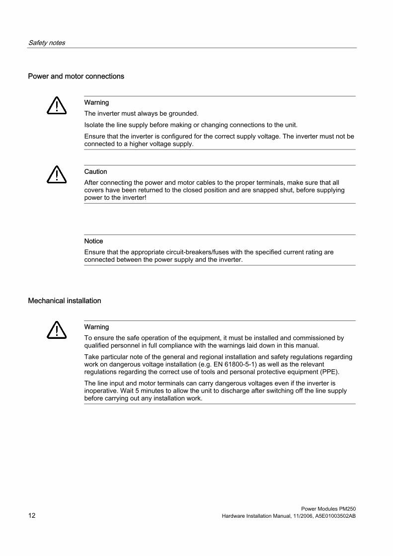
Power and motor connections
Warning The inverter must always be grounded. Isolate the line supply before making or changing connections to the unit. Ensure that the inverter is configured for the correct supply voltage. The inverter must not be connected to a higher voltage supply.
Caution After connecting the power and motor cables to the proper terminals, make sure that all covers have been returned to the closed position and are snapped shut, before supplying power to the inverter!
Notice Ensure that the appropriate circuit-breakers/fuses with the specified current rating are connected between the power supply and the inverter.
Mechanical installation
Warning To ensure the safe operation of the equipment, it must be installed and commissioned by qualified personnel in full compliance with the warnings laid down in this manual. Take particular note of the general and regional installation and safety regulations regarding work on dangerous voltage installation (e.g. EN 61800-5-1) as well as the relevant regulations regarding the correct use of tools and personal protective equipment (PPE). The line input and motor terminals can carry dangerous voltages even if the inverter is inoperative. Wait 5 minutes to allow the unit to discharge after switching off the line supply before carrying out any installation work.

Safety notes
Power Modules PM250 Hardware Installation Manual, 11/2006, A5E01003502AB 13
Electrical installation
Warning Power and motor connections The inverter must be grounded from the supply side and the motor side. If it is not grounded correctly, extremely dangerous conditions may arise which could prove potentially fatal. Isolate the mains electrical supply before making or changing connections to the unit. Ensure that the inverter is configured for the correct supply voltage – it must not be connected to a higher voltage supply.
Operation
Warning The inverter operates at high voltages. When operating electrical devices, it is impossible to avoid applying hazardous voltages to certain parts of the equipment. The power supply and motor terminals can carry dangerous voltages even if the inverter is inoperative. Wait five minutes to allow the unit to discharge after switching off the line supply before carrying out any installation work. Emergency Stop facilities according to EN 60204, IEC 204 (VDE 0113) must remain operative in all operating modes of the control equipment. Any disengagement of the Emergency Stop facility must not lead to an uncontrolled or an undefined restart of the equipment. Wherever faults occurring in the control equipment can lead to substantial material damage or even grievous bodily injury (that is, potentially dangerous faults), additional external precautions must be taken or facilities provided to ensure or enforce safe operation, even when a fault occurs (e.g. independent limit switches, mechanical interlocks, etc.). Certain parameter settings may cause the inverter to restart automatically after an input power failure, for example, the automatic restart function. Motor parameters must be accurately configured for motor overload protection to operate correctly. This equipment is suitable for use in a circuit capable of delivering not more than 10,000 symmetrical amperes (rms), for a maximum voltage of 480 V + 10 % when protected by an H, J or K type fuse, a circuit breaker or self-protected combination motor controller. The power modules are components with a high leakage current! Use of mobile radio device (e.g. telephones, walky-talkies) with a transmission power > 1 W in the immediate vicinity of the devices (< 1.5 m) can interfere with the functioning of the equipment!

Safety notes
Power Modules PM250 14 Hardware Installation Manual, 11/2006, A5E01003502AB
Repair
Warning Repairs on equipment may only be carried out by Siemens Service, by repair centers authorized by Siemens or by authorized personnel who are thoroughly acquainted with all the warnings and operating procedures contained in this manual. Any defective parts or components must be replaced using parts contained in the relevant spare parts list. Disconnect the power supply before opening the equipment for access.
Dismantling and disposal
Caution The packaging of the inverter is re-usable. Retain the packaging for future use. Easy-to-release screw and snap connectors allow you to break the unit down into its component parts. You can recycle these component parts, dispose of them in accordance with local requirements or return them to the manufacturer.

Power Modules PM250 Hardware Installation Manual, 11/2006, A5E01003502AB 15
Description 33.1 System Overview of SINAMICS G120 - overview
The SINAMICS G120 range The SINAMICS G120 inverter has been designed for the accurate and efficient control of the speed and torque for three-phase motors. The SINAMICS G120 system comprises two basic modules, the Control Unit (CU) and the Power Module (PM). The Control Units are divided into the following: • Standard CUs (CUs without fail-safe functions)
– CU240S – CU240S DP like CU 240S plus PROFIBUS DP interface
• CUs with fail-safe functions – CU240S DP-F like CU240S DP plus integrated fail-safe functions
The Power Modules are divided as follows: • PM240 Power module with dc braking functions, supply voltage 3 AC 400 V • PM250 Power module with regenerative mode, supply voltage 3 AC 400 V • PM260 Power module with regenerative mode, supply voltage 3 AC 690 V Control Units and Power modules are allowed to be combined in any possible configuration. See the respective manual for specific functions and features.

Description 3.2 Power Modules PM250
Power Modules PM250 16 Hardware Installation Manual, 11/2006, A5E01003502AB
3.2 Power Modules PM250
Overview The power modules are available with protection level IP 20 according to EN 60529, with integrated Class A filter in the following frame sizes and power ranges: • Frame size C, 5,5 kW … 11 kW • Frame size D, 15 kW … 22 kW • Frame size E, 30 kW … 37 kW • Frame size F, 45 kW … 75 kW The power modules have regenerative capability, where the regeneration limit is the nominal power (high overload) of the power module. The PM250 power modules can be used together with G120 standard Control Units or with G120 fail-safe control units.
3.3 Accessories for the PM250, 400 V
Description of accessories or spare parts A description how to use the individual options or spare parts is part of the option package itself. Ordering information and a brief functional description is given in the SINAMICS G120 catalog.
Power Module PM250 accessories • NEMA 1 kit • Screen termination kit • Brake relay and safe brake relay • Output reactors
Power Module spare parts • Fan.

Description 3.4 Block diagram
Power Modules PM250 Hardware Installation Manual, 11/2006, A5E01003502AB 17
3.4 Block diagram
Block diagram
Figure 3-1 Power module


Power Modules PM250 Hardware Installation Manual, 11/2006, A5E01003502AB 19
Installing/Mounting 4General rules for the environmental protection of the power modules
To ensure that the power module is installed in the correct environmental conditions, please ensure that you adhere to the following guidelines: • The power module is designed for IP20 protection, this means:
– It is protected from the ingress of solid foreign objects ≥ 12.5 mm (≥ 0.49 inches). – It is not protected against the ingress of water. – It is designed to be installed in an electrical cabinet.
• Keep the power module free from dust and dirt. • Keep the power module away from water, solvents and chemicals. • Keep the power module within the maximum and minimum operating temperatures. • Ensure that the correct level of ventilation and air flow is provided. • Ensure that good earthing/grounding practices are followed for each power module and
the cabinet.

Installing/Mounting 4.1 Mechanical Installation
Power Modules PM250 20 Hardware Installation Manual, 11/2006, A5E01003502AB
4.1 Mechanical Installation
Overview This section contains information about • distances to other equipment, • drill patterns, • dimensions and tightening torques • environmental conditions
Warning
To ensure the safe operation of the equipment, it must be installed and commissioned by qualified personnel in full compliance with the warnings laid down in this manual. Take particular note of the general and regional installation and safety regulations regarding work on dangerous voltage installation (e.g. EN 61800-5-1) as well as the relevant regulations regarding the correct use of tools and personal protective equipment (PPE). The terminals of the power module can carry dangerous voltages even if the inverter is inoperative. Wait 5 minutes to allow the unit to discharge after switching off the line supply before carrying out any installation work.
Distances to other equipment The power modules FSD to FSF can be mounted without any clearance at either side; power modules FSC need a side by side spacing of 50 mm (1.97 inches). When mounting the power modules one above the other, the specified environmental conditions must not be exceeded. Independent of this, these minimum distances above and below the power modules must be observed: • FSC: above and below 125 mm (4.92 inches) • FSD: above and below 300 mm (11.81 inches) • FSE: above and below 300 mm (11.81 inches) • FSF: above and below 350 mm (13.77 inches).

Installing/Mounting 4.1 Mechanical Installation
Power Modules PM250 Hardware Installation Manual, 11/2006, A5E01003502AB 21
4.1.1 Dimensions and drill patterns 400 V
Dimensions To allow the preliminary installation work to be undertaken, dimensions and drill patterns for the power modules are shown below.
Figure 4-1 Dimensions and drill patterns for the power modules

Installing/Mounting 4.2 Electrical Installation
Power Modules PM250 22 Hardware Installation Manual, 11/2006, A5E01003502AB
4.2 Electrical Installation
Overview This section gives information about • power distribution systems, • connecting the motor, • screening methods • motor connection star/delta
Warning
Power and motor connections • The inverter must be grounded from the supply side and the motor side. If the inverter
is not grounded correctly, extremely dangerous conditions may arise which could prove potentially fatal.
• Isolate the mains electrical supply before making or changing connections to the unit. • Input chokes must not be used. • RSCE of the power supply must be at least 100. • Ensure that the inverter is configured for the correct supply voltage – the inverter must
not be connected to a higher voltage supply. • If a residual-current device is used on the supply side of this electronic equipment for
protection in case of direct or indirect contact, only Type B is permitted! Otherwise a different protective measure must be employed, such as separation of the electronic equipment from the environment by double or reinforced insulation, or from the supply by a transformer!"
Caution
The control cables must be laid separately from the power cables. The connection must be carried out as shown in the installation section in this manual, to prevent inductive and capacitive interference from affecting the correct function of the system.
Note Ensure that the appropriate circuit-breakers/fuses with the specified current rating (see technical data) are connected between the power supply and the inverter.

Installing/Mounting 4.2 Electrical Installation
Power Modules PM250 Hardware Installation Manual, 11/2006, A5E01003502AB 23
4.2.1 Power distribution systems
Power Distribution Systems The power distribution systems described below, as defined in EN 60950, have been considered in the design of the inverter. In the next figures three phase systems are outlined. The three phase inverter must be connected to L1, L2 and L3. PE must always be connected.
Table 4-1 Power distribution systems
TN-S Power System TN-C-S Power System TN-C Power System
Exposed Conductive Parts
Exposed Conductive Parts
Exposed Conductive Parts
A TN-S power system has separate neutral and protective ground conductors throughout the system. It is the standard distribution system in the UK
In a TN-C-S power system, the neutral and protective functions are combined in a single part of the system.
In a TN-C power system, the neutral and protective functions are combined in a single conductor throughout the system.
4.2.2 Permissible Cable Length (PM250, 400 V)
Motor cables The use of unshielded motor cables is possible. However to meet C2 EMI class, shielded cables with appropriate EMI installation are required. The inverters will operate at full specification with cable lengths as follows: • 100 m (328 ft) with unscreened cables • 25 m (82 ft) with screened cables

Installing/Mounting 4.2 Electrical Installation
Power Modules PM250 24 Hardware Installation Manual, 11/2006, A5E01003502AB
Table 4-2 Using output chokes as specified in the catalog, the following cable length are possible:
• 100 m with screened cables at a supply voltage from 400 V … 480 V • 150 m FSC with screened cables at a supply voltage from 380 V … 400 V
FSC with unscreened cables at a supply voltage from 400 V … 480 V • 200 m FSD … FSF with screened cables at a supply voltage from 380 V … 400 V
FSD … FSF with screened cables at a supply voltage from 400 V … 480 V • 225 m FSC with unscreened cables at a supply voltage from 380 V … 400 V
• 300 m FSD … FSF with unscreened cables at a supply voltage from 380 V … 400 V FSD … FSF with unscreened cables at a supply voltage from 400 V … 480 V
Table 4-3 Cable cross section
FSC • 5,5 kW: • 7,5 kW: • 11 kW:
4 mm2 … 10 mm2 4 mm2 … 10 mm2 6 mm2 … 10 mm2
12 AWG … 8 AWG 12 AWG … 8 AWG 10 AWG … 8 AWG
Tightening Torques: 2.25 Nm / 19.9 lbf.in
FSD • 15 kW • 18,5 kW: • 22 kW:
10 mm2 … 35 mm2 10 mm2 … 35 mm2 16 mm2 … 35 mm2
7 AWG … 2 AWG 7 AWG … 2 AWG 5 AWG … 2 AWG
Tightening Torques: 6 Nm / 53 lbf.in
FSE • 30 kW: • 37 kW:
25 mm2 … 35 mm2 25 mm2 … 35 mm2
3 AWG … 2 AWG 3 AWG … 2 AWG
Tightening Torques: 6 Nm / 53 lbf.in
FSF • 45 kW • 55 kW: • 75 kW:
35 mm2 … 150 mm2 70 mm2 … 150 mm2 95 mm2 … 150 mm2
2 AWG … -5 AWG -2 AWG … -5 AWG -3 AWG … -5 AWG
Tightening Torques: 13 Nm / 115 lbf.in

Installing/Mounting 4.2 Electrical Installation
Power Modules PM250 Hardware Installation Manual, 11/2006, A5E01003502AB 25
Caution The cable cross section for earhting must be the same as the motor cables but at least 10 mm2 (Cu) or 16 mm2 (Al).
4.2.3 Access to power and motor terminals (PM250)
Access to power and motor terminals The terminals for Frame size C can be accessed directly, without removing any cover.
Figure 4-2 Access to power and motor terminals on FSC
Frame size F terminals covers are accessed by releasing the latch on the side of the terminal covers with a suitable flat-bladed screwdriver. The cover can then be pushed upwards and locked into position, as shown in the figure below.

Installing/Mounting 4.2 Electrical Installation
Power Modules PM250 26 Hardware Installation Manual, 11/2006, A5E01003502AB
Figure 4-3 Access to power and motor terminals on FSD, FSE and FSF
Power and motor terminal layout The figures below show the layout of the power and motor terminals of the PM250 Frame Sizes C… F.
Figure 4-4 PM250 Power and motor terminals FSC

Installing/Mounting 4.2 Electrical Installation
Power Modules PM250 Hardware Installation Manual, 11/2006, A5E01003502AB 27
Figure 4-5 PM250 Power and motor terminals FSD … FSF
Operation with Residual Current Devices (RCD) If an RCD (also referred to as an ELCB or a RCCB) is fitted, the Power Module will operate without nuisance tripping provided that: • A type B RCD is used. • The trip limit of the RCD is 300 mA. • The neutral of the supply is grounded. • Only one power module is supplied from each RCD. • The output cables are less than 50 m (164 ft) screened or 100 m (328 ft) unscreened.
Avoiding Electromagnetic Interference (EMI) The inverters are designed to operate in an industrial environment where a high level of EMI can be expected. Most installations do not give problems. However, it is good engineering practice to conform to the following guidelines - this will reduce the likelyhood of problems during operation.

Installing/Mounting 4.2 Electrical Installation
Power Modules PM250 28 Hardware Installation Manual, 11/2006, A5E01003502AB
Actions to take • Ensure that all equipment in the cubicle is well grounded using short, thick grounding
cable connected to a common star point or busbar. • Make sure that any control equipment (such as a PLC) connected to the inverter is
connected to the same ground or star point as the inverter using a short thick link. • Connect the return ground from the motors directly to the ground connection (PE) on the
associated inverter. • Flat conductors are preferred as they have lower impedance at higher frequencies. • Terminate the ends of the cable neatly, ensuring that unscreened wires are as short as
possible. • Separate the control cables from the power cables as much as possible, using separate
trunking, if the cables cross they should cross at 90º to each other. • Whenever possible, use screened leads for the connections to the control circuitry. • Ensure that the contactors in the cubicle are suppressed, either with R-C suppressors for
AC contactors or 'flywheel' diodes for DC contactors fitted to the coils. Varistor suppressors are also effective. This is important when the contactors are controlled from the inverter relay.
• Use screened or armored cables for the motor connections and ground the screen at both ends using the cable clamps.
Warning
Safety regulations must not be compromised when installing inverters!
Screening methods For all frame sizes the Screen Termination Kit is supplied as an optional extra. It allows easy and efficient connection of the necessary screening. For further details on the Screen Termination Kit, please refer to the SINAMICS G120 catalog.
Screening without a Screen Termination Kit Should a Screen Termination Kit not be available, then the inverter can be screened using the methodology shown in the figure below. This diagram shows both methodologies of screening.
Note The EMI illustration below is not to scale.

Installing/Mounting 4.2 Electrical Installation
Power Modules PM250 Hardware Installation Manual, 11/2006, A5E01003502AB 29
Figure 4-6 Example of wiring to minimize the effect of EMI
Table 4-4 Legend to the drawing
1 Mains power input 5 Screened cables 2 Motor cable 6 Screen termination kit 3 Metal back plate 7 Cable clamp
8 Brake Module 4 Use suitable clips to fix motor and power cable screen securely to metal back plate
9 Terminal blocks
Installing/Mounting 4.2 Electrical Installation
Power Modules PM250 30 Hardware Installation Manual, 11/2006, A5E01003502AB
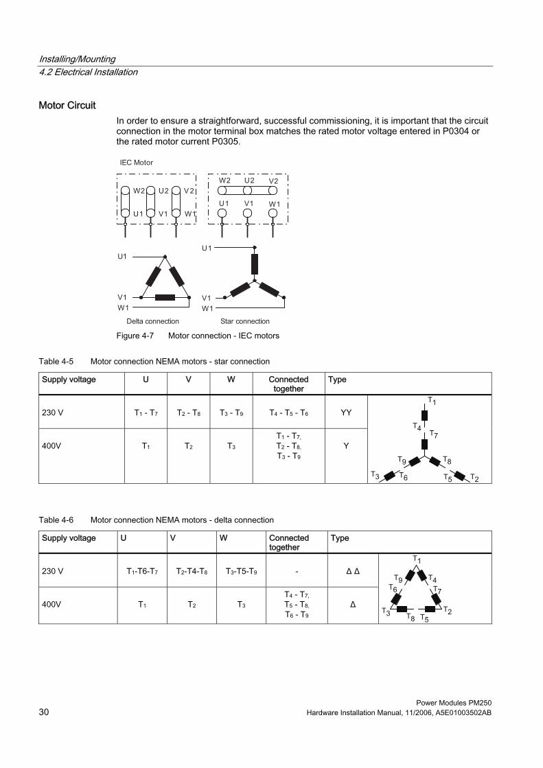
Motor Circuit In order to ensure a straightforward, successful commissioning, it is important that the circuit connection in the motor terminal box matches the rated motor voltage entered in P0304 or the rated motor current P0305.
Figure 4-7 Motor connection - IEC motors
Table 4-5 Motor connection NEMA motors - star connection
Supply voltage U V W Connected together
Type
230 V
T1 - T7
T2 - T8
T3 - T9
T4 - T5 - T6
YY
400V
T1
T2
T3
T1 - T7, T2 - T8, T3 - T9
Y
Table 4-6 Motor connection NEMA motors - delta connection
Supply voltage U V W Connected together
Type
230 V
T1-T6-T7
T2-T4-T8
T3-T5-T9
-
Δ Δ
400V
T1
T2
T3
T4 - T7, T5 - T8, T6 - T9
Δ

Installing/Mounting 4.2 Electrical Installation
Power Modules PM250 Hardware Installation Manual, 11/2006, A5E01003502AB 31
The following must be noted when entering the rating plate data or the ECD data: • The outer conductor voltage/phase-to-phase voltage (voltage U12 between outer
conductors L1, L2) and the outer conductor current (phase current) I1 are always specified on the rating plate.
• The rated motor voltage and the rated motor current must always be entered according to the motor circuit configuration (either delta/star circuit configuration).
• If rated motor data that are available are not consistent with the motor circuit configuration, then an appropriate conversion should be made which is then entered.
• If equivalent circuit diagram data is available, then these should be entered according to the motor circuit configuration. If there is no consistency between the motor circuit configuration and equivalent circuit diagram data, then the equivalent circuit diagram data should be converted and entered corresponding to the data on the rating plate.
Figure 4-8 Star/Delta configuration
Note The precise equivalent circuit diagram data is of extreme importance regarding the stability of the closed-loop vector control and for the voltage boost applied to the V/f characteristic. Equivalent circuit diagram data can only be estimated from the rating plate data; this is the reason that equivalent circuit diagram data is either determined • using the motor data identification, or • is entered from a motor data sheet that may be available.

Installing/Mounting 4.2 Electrical Installation
Power Modules PM250 32 Hardware Installation Manual, 11/2006, A5E01003502AB
87 Hz characteristic When a motor with a delta circuit configuration (e.g. VN∆, motor = 230 V) is fed from a frequency inverter, where the rated voltage corresponds to the star circuit configuration (e.g. 400 V frequency inverter), then it is important to proceed as follows and observe the following: • The motor must have the appropriate voltage. • Above the rated motor frequency, the iron losses in the motor increase over-
proportionally. This is the reason that above this frequency, the thermal motor torque should be reduced.
• For the quick commissioning, the rating plate data for the delta circuit configuration should be entered or must be appropriately converted.
• The inverter must be designed for the higher current (delta circuit configuration). • The 87 Hz characteristic is independent of the control type and can therefore be used
both for V/f control as well as for closed-loop vector control. • When using the 87 Hz characteristic, the mechanical motor limits must be taken into
account. For the 87 Hz characteristic, the ratio between the voltage and frequency (V/f characteristic) remain constant. This is the reason that the following relationships apply:
Figure 4-9 V/f characteristic
Table 4-7 Example 1LA7060-4AB10
Delta circuit configuration
87 Hz characteristic
Star circuit configuration
P0304 Rated motor voltage 230 V 400 V 400 V P0305 Rated motor current 0.73 A 0.73 A 0.42 A P0307 Rated motor power 120 W 207 W 120 W P0308 cos φ 0.75 0.75 0.75 P0310 Rated motor frequency 50 Hz 87 Hz 50 Hz P0311 Rated motor speed 1350 RPM 2460 RPM 1350 RPM P0314 Motor pole pairs 2 2 2
Contrary to the OP, the STARTER commissioning (start-up) program offers a mask-orientated quick commissioning. On the other hand, the OP offers, in conjunction with the inverter, parameter-orientated quick commissioning.

Installing/Mounting 4.2 Electrical Installation
Power Modules PM250 Hardware Installation Manual, 11/2006, A5E01003502AB 33
Fitting the Control Unit to the Power Module The Control Unit is snapped on to the Power Module as shown in the figure below. To disconnect the CU push the release button on top of the PM. The process of fitting the Control Unit to the Power Module is the same technique independent from the type of G120 control unit or G120 power module.
Figure 4-10 Fitting the control unit to the power module
24 V power supply Normally the CU is supplied with 24 V from Power Module. But it is also possible to use an external DC 24 V supply (20.4 V … 28.8 V, 0.5 A). It must be connected to the Control Unit terminals 31 (+ 24 V In) and 32 (0 V In). Some reasons for using an external 24 V power supply are: • The PROFIBUS DP interface is required to communicate with the Control Unit when the
Power Module mains power is not present • Supply for 24 V encoder
Caution
Care must be taken to ensure that the 24 V DC power is connected correctly or damage to the Control Unit may occur. Max. cable length on 24 V DC supply and I/O cables connected to CU must not exceed 10 m. Use of unscreened cables is possible however we recommend to use screened cables.

Installing/Mounting 4.2 Electrical Installation
Power Modules PM250 34 Hardware Installation Manual, 11/2006, A5E01003502AB
Note If the CU is externally powered with 24 V DC but the power module is disconected from the mains supply, the faults F0001 … F0028 are not generated.

Power Modules PM250 Hardware Installation Manual, 11/2006, A5E01003502AB 35
Operation (hardware) 5Overview
This section describes the possibilities to exchange inverter comonents, power modules or control units, and the necesarry actions, depending on the swap type. The following swaps are allowed: • CU swap (neither PM nor CU powered) • PM swap (neither PM nor CU powered) • PM swap (CU externally powered)
Note A swap is indicated by a F395. A downlaod fault during swap will be indicated by F0061 or F0063. If F0061 or F0063 occurs during startup it cannot be cleard except via a power cycle.

Operation (hardware) 5.1 Swap behavior
Power Modules PM250 36 Hardware Installation Manual, 11/2006, A5E01003502AB
5.1 Swap behavior
CU swap, PM swap (whether PM nor CU powered) Constraints: MMC with valid Parameter set plugged • Swap after power on detected, Parameter MMC -> RAM/EEPROM, inverter runs into
F0395 • Confirmation for standard CU or acceptance test in case of fail-safe CU required constraints: no MMC • Swap after power on detected, Parameter EEPROM -> RAM, inverter runs into F0395 • Commissioning recommended - otherwise inverter runs with parameter settings from
EEPROM • Confirmation for standard CU or acceptance test in case of fail-safe CU required
PM swap (CU externally powered) Constraints: MMC with valid Parameter set plugged • Swap detected, Parameter MMC -> RAM/EEPROM, inverter runs into F0395 • Confirmation for standard CU or acceptance test in case of fail-safe CU required Constraints: no MMC • Swap detected, Parameter EEPROM -> RAM, inverter runs into F0395 • If the parameters, already held in the EEPROM are ok there is no commissioning
necesarry. • Confirmation for standard CU or acceptance test in case of fail-safe CU required
Note After a PM swap without MMC the parameter settings only stored in RAM will be lost

Operation (hardware) 5.1 Swap behavior
Power Modules PM250 Hardware Installation Manual, 11/2006, A5E01003502AB 37
Successful swap After a successful swap, F0395 will be displayed. • In case of a standard CU a confirmation is necessary. • In the case of CUs with fail-safe functions, an acceptance test must be performed. Confirmation On standard CUs the current parameter set needs to be checked and confirmed by clearing F0395. It can be cleared via: • Digital input or PLC signal (depends on the settings of P0700) • setting P7844 = 0. • Via the button on the OP
Warning
The user is responsible for ensuring that the parameters held in the CU are the correct parameters for their application.
Acceptance test On CUs with fail-safe functions it is necessary to do an acceptance test (refer to the "Fail-safe functions" section in this manual). To clear F0395 on CUs with fail-safe functions the following procedure has to be followed: • P0010 = 30 • P9761 = safety password • P7844 = 0 • Carry out acceptance test
Swap fault A swap fault is indicated if the automatic download fails. In this case, the CU will return to the parameter set previously held in the EEPROM and F0395 as well as one of F0061, F0062 and F0063 will be generated. First F0395 must be cleared via: • Digital input or PLC signal (depends on the settings of P0700) • setting P7844 = 0. • Via the button on the OP In the next step F0061 / F0062 or F0063 has to be cleared via power cycle.
Note F0395 cannot be cleared via power cycle. F0061, F0062 and F0063 can only be cleared via power cycle.

Operation (hardware) 5.1 Swap behavior
Power Modules PM250 38 Hardware Installation Manual, 11/2006, A5E01003502AB
In case of a swap fault check, whether the MMC is defective or a parameter set clone00.bin is available or the parameter set is valid. A valid parameter set means, it is not from a different type (eg. CU20S DP and CU240S or failsafe and standard CUs)
Rules regarding swap and hot swap There are a number of scenarios where a swap or hot swap can take place, each with their own unique set of conditions that must be observed.
Danger Do not attempt to hot swap a power module (PM) Before attempting to swap a PM it must be fully powered-down. Any attempt to swap-out a PM when power is still applied could result in death of personnel and severe damage to property and equipment.
Warning Swap restrictions Before performing a swap take care of the following: • It is the responsibility of the user to ensure that only CUs of the same type are swapped • It is the responsibility of the user to ensure that the MMC contains the correct parameter
set • It is the responsibility of the user to ensure that only PMs of the same type and power
rating are swapped. • It is the responsibility of the user to ensure that the application is in a safe state before
any swap of equipment is performed.

Operation (hardware) 5.1 Swap behavior
Power Modules PM250 Hardware Installation Manual, 11/2006, A5E01003502AB 39
Swapping a CU The following procedure is given as a guide to perform a swap of a CU.
Caution Data set compatibility To ensure complete data set compatibility, it is recommended to perform an upload of the parameter set from the CU to a new MMC prior to swapping the CU.
Before performing a CU swap take care of the following: 1. The PM is powered-down and disconnected. 2. Wait 5 minutes to allow the unit to discharge after switching off the line supply before
carrying out any installation work. 3. Remove the two-part terminals that are actually wired on the CU. 4. Remove the MMC. 5. Remove the CU from the PM. Before switching on Power supply to the inverter take care of the following: 1. Fit the new CU to the PM. 2. Reconnect the two-part terminals to the CU. 3. Insert the MMC into the MMC-slot of the CU.
Swapping the PM
Caution To ensure complete data set compatibility, make sure that all parameters are stored in the EEPROM of the Control Unit (see P0014 or P0971) prior to swapping the PM).
Before performing a PM swap take care of the following: 1. The PM is powered-down and disconnected. 2. Wait 5 minutes to allow the unit to discharge after switching off the line supply before
carrying out any installation work. Before switching on Power supply take care of the following: 1. The new PM is properly installed and connected. 2. The CU is fitted back on the PM.

Operation (hardware) 5.2 Regeneration
Power Modules PM250 40 Hardware Installation Manual, 11/2006, A5E01003502AB
5.2 Regeneration
Description The power modules, described in this manual, are able to continously feed back regenerative power to mains supply network. The regenerative power capability depends on the motor speed and on current or voltage limiting parameters. The maximum regenerative power is limited to 100 % of the nominal power (high overload) of the power module.
Regeneration in case of V/f control The regenerative power can be limited via P0640. If the regenerative power exceeds the limit for more than 5 s the inverter will trip with F0028.
Regeneration in case of vector control The regenerative power can be limited via P1531. If the regenerative power exceeds the limit the drive will not be able to hold its setpoint. The following graph shows the limiting parameters.
Figure 5-1 Regenerative capability

Power Modules PM250 Hardware Installation Manual, 11/2006, A5E01003502AB 41
Technical data 66.1 Performance Ratings (PM250)
SINAMICS G120 Power Module
Table 6-1 Performance ratings
Feature Specification 3 AC 380 V … 480 ± 10 % High Overload: 5.5 kW … 75 kW (7.4 hp … 100 hp)
Line operating voltage & power ranges
Light Overload: 7.5 kW … 90 kW (10 hp … 121 hp) Input frequency 47 Hz … 63 Hz Output frequency 0 Hz … 200 Hz cos φ 0.95 Inverter efficiency 95 % … 97 %
1.5 x Nominal output current (150 % overload) for 57 s every 300 s Overload capability (HO) 2 x Nominal output current (200 % overload) for 3 s every 300 s, 20,000 cycles 1.1 x Nominal output current (110 % overload) for 57 s every 300 s Overload capability (LO) 1.5 x Nominal output current (150 % overload) for 3 s every 300 s, 70,000 cycles
Inrush current Less than rated input current Pulse frequency 4 kHz (factory setting)
adjustable in 2 kHz-steps from • 4 kHz … 16 kHz for FSC to FSE • 4 kHz … 8 kHz for FSF
Electromagnetic compatibility
Integrated Class A filters
Braking Regeneration (up to 100 % output rating) Protection level IP20 according to EN 60529 Storage temperature -40 °C … +70 °C (-40 °F … 158 °F) Protection features Undervoltage, Overvoltage, Overload, Ground faults, Short circuit, Stall
prevention, Motor blocking protection, Motor overtemperature, Power Module overtemperature, Parameter interlock
Standards CE, C-tick CE marked Conformity with EC Low Voltage Directive 73/23/EEC and filtered
versions also Electromagnetic Compatibility Directive 89/336/EEC

Technical data 6.1 Performance Ratings (PM250)
Power Modules PM250 42 Hardware Installation Manual, 11/2006, A5E01003502AB
Power Module PM250 Specifications
Caution High Overload (HO) and Light Overload (LO) input currents The input current depends on the motor load and the line impedance. The given values apply for a load representing the rated power (based on high overload current) for a line impedance of Vk = 1 %.
Notice UL Fuses In order that the system is in compliance with UL, UL-certified fuses must be used with the appropriate rated current.
Table 6-2 PM250 Frame Sizes C, 3 AC 380 V … 480 V, ± 10 % (with built-in Class A Filter)
Order No. 6SL3225 - 0BE25-5AA0 0BE27-5AA0 0BE31-1AA0 [kW] 5.5 7.5 11.0 Output Rating (HO) [hp] 7.5 10.0 15.0
Output Power [kVA] 10.1 14.0 19.8 Rated Input Current [A] 15.5 23.1 32.6 HO Output Current [A] 13.2 18.4 26.0 LO Output Current [A] 19.0 26.0 32.0 Fuse [A] 20 32 35 Required cooling air flow l/s 38 38 38
[mm2] 2.5 … 10 4 … 10 6 … 10 Input Cable / Output Cable [awg] 14 … 8 12 … 8 10 … 8
[kg] 7.0 7.0 7.0 Weight [lbs] 15.4 15.4 15.4

Technical data 6.1 Performance Ratings (PM250)
Power Modules PM250 Hardware Installation Manual, 11/2006, A5E01003502AB 43
Table 6-3 PM250 Frame Sizes D, 3 AC 380 V … 480 V, ±10 % (with built-in Class A Filter)
Order No. 6SL3225 - 0BE31-5AA0 0BE31-8AA0 0BE32-2AA0 [kW] 15.0 18.5 22.0 Output Rating (HO) [hp] 20.0 25.0 30.0
Output Power [kVA] 24.4 29.0 34.3 Rated Input Current [A] 30.0 35.0 42.0 HO Output Current [A] 32.0 38.0 45.0 LO Input Current [A] 37.2 54.7 74.8 LO Output Current [A] 45.2 45.0 60.0 Fuse [A] 50 63 80 Required cooling air flow l/s 22 22 39
[mm2] 10 … 35 10 … 35 16 … 35 Input Cable / Output Cable [awg] 7 … 2 7 … 2 5 … 2
[kg] 16.0 16.0 16.0 Weight [lbs] 37.0 37.0 37.0
Table 6-4 PM250 Frame Sizes E, 3 AC 380 V … 480 V, ±10 % (with built-in Class A Filter)
Order No. 6SL3225 - 0BE33-0AA0 0BE33-7AA0 [kW] 30.0 37.0 Output Rating (HO) [hp] 40.0 50.0
Output Power [kVA] 47.3 57.2 Rated Input Current [A] 56.0 70.0 HO Output Current [A] 60.0 75.0 LO Input Current [A] 91.0 111.0 LO Output Current [A] 75.0 90.0 Fuse [A] 100 125 Required cooling air flow l/s 22 39
[mm2] 25 … 35 25 … 35 Input Cable Min. [awg] 3 … 2 3 … 2 [kg] 23.0 23.0 Weight [lbs] 48.0 48.0

Technical data 6.1 Performance Ratings (PM250)
Power Modules PM250 44 Hardware Installation Manual, 11/2006, A5E01003502AB
Table 6-5 PM250 Frame Sizes F, 3 AC 380 V … 480 V, ±10 % (with built-in Class A Filter)
Order No. 6SL3225 - 0BE34-5AA0 0BE35-5AA0 0BE37-5AA0 [kW] 45.0 55.0 75 Output Rating (HO) [hp] 60.0 75.0 100.0
Output Power [kVA] 68.6 83.8 110.5 Rated Input Current [A] 84.0 103.0 135.0 HO Output Current [A] -- 110.0 145.0 LO Input Current [A] 143.0 190.0 223.0 LO Output Current [A] 110.0 145.0 178.0 Fuse [A] 160 200 250 Required cooling air flow l/s 94 94 117
[mm2] 35 … 150 70 … 150 95 … 150 Input Cable Min. [awg] 2 … - 5 - 2 … - 5 - 3 … - 5 [kg] 52.0 52.0 52.0 Weight [lbs] 165.0 165.0 165.0
Relationship between pulse frequency and current reduction
Table 6-6 Current reduction depending on pulse frequency
Nominal Current
Output current at pulse frequency of Nominal Power (HO) 4 kHz 6 kHz 8 kHz 10 kHz 12 kHz 14 kHz 16 kHz
Mains voltage
kW A A A A A A A 5.5 13.2 12.5 11.9 10.6 9.2 7.9 6.6 7.5 19.0 18.1 17.1 15.2 13.3 11.4 9.5 11.0 26.0 24.7 23.4 20.8 18.2 15.6 13.0 15.0 38.0 32.0 27.0 23.0 19.0 17.0 15.0 18.5 45.0 38.0 32.0 27.0 23.0 20.0 18.0 22.0 60.0 51.0 42.0 36.0 30.0 27.0 24.0 30.0 75.0 64.0 53.0 45.0 38.0 34.0 30.0 37.0 90.0 77.0 63.0 -- -- -- -- 45.0 110.0 94.0 77.0 -- -- -- -- 55.0 145.0 123.0 102 -- -- -- --
3 AC 400 V
75.0 178 151 125 -- -- -- --

Technical data 6.1 Performance Ratings (PM250)
Power Modules PM250 Hardware Installation Manual, 11/2006, A5E01003502AB 45
Temperature The operating temperature range is shown diagramatically in the figure below:
Figure 6-1 Power derating for temperature
Humidity range Relative air humidity for the SINAMICS G120 is ≤ 95 % non-condensing. In areas of high relative humidity, measures should be taken to ensure that condensation does not form within or around the SINAMICS G120. Anti-condensation heaters are commonly used to prevent the formation of condensation.
Altitude If the SINAMICS G120 is to be installed at an altitude > 1000 m (> 3280 ft) derating will be required. The figures below show the derating required according to altitude.

Technical data 6.1 Performance Ratings (PM250)
Power Modules PM250 46 Hardware Installation Manual, 11/2006, A5E01003502AB
Figure 6-2 Derating for altitude
Shock and vibration Do not drop the SINAMICS G120 or expose to sudden shock. Do not install the SINAMICS G120 in an area where it is likely to be exposed to constant vibration.
Electromagnetic radiation Do not install the SINAMICS G120 near sources of electromagnetic radiation.
Atmospheric pollution Do not install the SINAMICS G120 in an environment which contains atmospheric pollutants such as dust and/or corrosive gases.
Water Take care to site the SINAMICS G120 away from potential water hazards, for example, do not install the SINAMICS G120 beneath pipes that are subject to condensation. Avoid installing the SINAMICS G120 where excessive humidity and condensation may occur.

Technical data 6.1 Performance Ratings (PM250)
Power Modules PM250 Hardware Installation Manual, 11/2006, A5E01003502AB 47
Installation and cooling
Caution The SINAMICS G120 Power Module MUST NOT be mounted horizontally.
When mounting SINAMICS G120 Power Modules one above the other, the specified environmental conditions and clearance must not be exceeded (see Dimension Drawings) No equipment that could have a negative effect on the flow of cooling air should be installed in this area. Make sure that the cooling vents in the SINAMICS G120 Power Module are positioned correctly to allow the free movement of air. Make sure that there is an adequate airflow through the cubicle as follows: 1. Using the formula below, calculate the airflow required:
Airflow (m3/hr) = (Dissipated Watts / ΔT) x 3.1 2. If necessary, install cubicle cooling fans.
Note Dissipation (Watts) = 3 % to 5 % of the SINAMICS G120 Power Module rating. ΔT = Allowable temperature rise within the cubicle in °C. 3.1 = Specific heat of air at sea level.


Power Modules PM250 Hardware Installation Manual, 11/2006, A5E01003502AB 49
Dimensional drawings 7Power Module PM250 Dimensional Drawings
The dimensional drawings for the power modules are shown in the figures below.
Figure 7-1 Dimensional drawing PM250 FSC, 400V

Dimensional drawings
Power Modules PM250 50 Hardware Installation Manual, 11/2006, A5E01003502AB
Figure 7-2 Dimensional drawing PM250 FSD, 400V (filtered)

Dimensional drawings
Power Modules PM250 Hardware Installation Manual, 11/2006, A5E01003502AB 51
Figure 7-3 Dimensional drawing PM250 FSE, 400V (filtered)

Dimensional drawings
Power Modules PM250 52 Hardware Installation Manual, 11/2006, A5E01003502AB
Figure 7-4 Dimensional drawing PM250 FSF, 400V (filtered)

Power Modules PM250 Hardware Installation Manual, 11/2006, A5E01003502AB 53
Spare parts/Accessories 8NEMA 1 kit
The NEMA 1 kit has been designed to provide some protection against limited amounts of falling dirt in an indoor environment. The level of protection does not protect against falling liquids. The NEMA 1 kit only provides protection for the inverter itself and does not protect any of the footprint options or the DIN rail kit. The kit provides protection for both the power module and the control unit including easy access to the MMC on the control unit. The NEMA 1 kit consists of the following components: • Top cover (to protect the top of the inverter). • Metal glanding box (to allow the correct termination of control cables). • Gland box cover (to ensure that the control cables can not be touched accidentally).
Screen termination kit The screen termination kit has been designed to allow the termination of control, mains and power cables to ensure the correct electrical grounding to the inverter. For FSC and larger the screen termination kits provides for the termination of at least 4 screened cables.
Brake modules The brake modules are designed to provide the interface between the Control Module/Power Module and the brake solenoid of a motor. There are two versions: • Brake module – this provides the basic braking control function. • Safe brake module – this provides for the braking control function within a safety
integrated system. To adhere to the requirements of a safety integrated system, the safe brake module has been designed to allow a variable voltage to be given to the safe brake module to allow the system to determine if the brake module is functioning correctly without actually activating the braking function.
The brake modules can be panel mounted, wall mounted or mounted on the screen termination plates and gland kits.
Output choke Output chokes can be used to reduce the capacitive compensation currents and dV/dt in the case of motor cables greater than 50 m [164 ft] (shielded) or less than 100 m [328 ft] unshielded.

Spare parts/Accessories 8.1 Cooling Fan
Power Modules PM250 54 Hardware Installation Manual, 11/2006, A5E01003502AB
8.1 Cooling Fan
Replacing a Cooling Fan The power modules have been designed to allow the cooling fans to be replaced. The procedure how to replace a fan is described in the following. Furthermore an illustrated description is part of the fan package. 1. Power-down the inverter. 2. Remove the Control Unit from the inverter. 3. Disconnect all the cables from the Power Module. 4. Remove the fan cover. 5. Release the fan cable connectors. 6. Slide the cooling fan out from the inverter. 7. Fit the new cooling fan into the fan housing area (make sure that the arrow on the fan is
pointing upwards) . 8. Re-attach the fan cable connector(s). 9. Replace the fan cover. 10. Reconnect all the cables to the Power Module. 11. Reattach the Control Unit. 12. Check that the installation is correct and safely installed. 13. Apply power the system. 14. Check that the cooling fan(s) are running correctly.

Spare parts/Accessories 8.2 Brake Control Relays
Power Modules PM250 Hardware Installation Manual, 11/2006, A5E01003502AB 55
8.2 Brake Control Relays
Overview There are two types of brake control relays: • Brake Module (Relay Brake Module) • Safe Brake Module (Safe Brake Module) The Safe Brake Module and the Brake Module are different variants of the same device (for details see option description "Brake Module Instructions". Connections of Brake Module and Safe Brake Relay:
Figure 8-1 Brake Relay
M3~
PEBrake ModuleTo Power
Module (A/B)
toPower Module
Figure 8-2 Wiring of Brake Relay

Spare parts/Accessories 8.2 Brake Control Relays
Power Modules PM250 56 Hardware Installation Manual, 11/2006, A5E01003502AB
Figure 8-3 Safe Brake Module
M3~
PESafeBrake
Module
To Power Module (A/B)
toPower Module
Figure 8-4 Wiring of Safe Brake Module
With the Safe Brake Module 24 V motor brakes up to a current consumption of 2 A can be operated. Necessary is an external controlled power supply for 2.5 A and an output voltage which can be adjusted at a voltage of 26 V, e.g. SITOP modular. The higher voltage is required to compensate the voltage drop across the cables to the coil of the brake.
Note On fail-safe reasons it is not allowed to take the 24 V supply of the Control Unit. The power supply for the Safe Brake Module must be a separate additional power supply. During power ON for the drive it is necessary to supply the Safe Brake Module first, so that the Control Unit is able to check its function, otherwise the fault F1601 will occur.
The Safe Brake Module is designed to react to a stepped voltage input, which allows the braking mechanism to be tested. The Brake Module does not have this functionality.

Spare parts/Accessories 8.2 Brake Control Relays
Power Modules PM250 Hardware Installation Manual, 11/2006, A5E01003502AB 57
Note During forced dynamisation all connections of the Safe Brake Module are checked but in operation the connection between Safe Brake Module and brake coil is not monitored.
Triggering the Brake Control with Standard Control Units The motor brake function can be activated or deactivated via P1215. It controls a brake relay, connected to the power module. This Brake Module controls an electro-mechanical brake, which is always closed when powered down. P1215 = 0 (motor brake not active - factory setting), that means, if a brake is available, it will be closed to prevent the motor against unintended moves, e.g. after a parameter download. P1215 = 1 (motor brake active) the brake will be controlled via terminals A and B on the power module.
Triggering the Brake Control with Contol Units with fail-safe functions Prerequisite: P1215 = 1
Warning The brake can be triggered via both, a Brake Module and a Safe Brake Relay. Triggering via a Brake Module is not fail-safe!
For a fail-safe triggering of a Safe Brake Module the following parameters must be set: P9602 = P9802 = 1 (factory setting is 0). If P9602 ≠ P9802 a fault will be generated. In case of P9602 = P9802 = 1 a test signal regarding the signal to the Safe Brake Control is generated and monitored. This test signal does not interfere with the normal function of the mechanical brake. If the mechanical brake is fitted and the test fails, a fault condition will be indicated by the inverter. If the Safe Brake Control is deactivated by setting P9602 = P9802 = 0 the Safe Brake Module will still work as intendet but will not be monitored in a safe way.


Power Modules PM250 Hardware Installation Manual, 11/2006, A5E01003502AB 59
Appendix AA.1 Electromagnetic Compatibility
Electromagnetic compatibility All manufacturers/assemblers of electrical apparatus which "performs a complete intrinsic function and is placed on the market as a single unit intended for the end user" must comply with the EMC directive EC/89/336. There are three routes for the manufacturer/assembler to demonstrate compliance:
Self-certification This is a manufacturer's declaration that the European standards applicable to the electrical environment for which the apparatus is intended have been met. Only standards that have been officially published in the Official Journal of the European Community can be cited in the manufacturer's declaration.
Technical construction file A technical construction file can be prepared for the apparatus describing its EMC characteristics. This file must be approved by a ‘Competent Body’ appointed by the appropriate European government organization. This approach allows the use of standards that are still in preparation.
EMC Standards The SINAMICS G120 drives have been tested in accordance with the EMC Product Standard EN 61800-3:2004.
Appendix A.2 Definition of the EMC Environment and Categories
Power Modules PM250 60 Hardware Installation Manual, 11/2006, A5E01003502AB
A.2 Definition of the EMC Environment and Categories
Classification of EMC performance The EMC environment and categories are defined within the EMC Product Standard EN 61800-3, as follows:
First Environment An environment that includes domestic premises and establishments that are connected directly to a public low-voltage power supply network without the use of an intermediate transformer.
Note For example: houses, apartments, commercial premises or offices in a residential building.
Second Environment An environment that includes industrial premises and establishments that are not connected directly to a public low-voltage power supply network.
Note For example: industrial and technical areas of buildings fed from a dedicated transformer.
Category C1 Power Drive System (PDS) of rated voltage less than 1000 V intended for use in the First (Domestic) Environment.
Category C2 Power Drive System (PDS) of rated voltage less than 1000 V, which is neither a plug in device nor a movable device, and when used in the First (Domestic) Environment, is only intended to be installed and commissioned by a professional.
Note A professional is a person or an organization having necessary skills in installing and/or commissioning a Power Drive System (PDS), including their EMC aspects.

Appendix A.2 Definition of the EMC Environment and Categories
Power Modules PM250 Hardware Installation Manual, 11/2006, A5E01003502AB 61
Category C3 Power Drive System (PDS) of rated voltage less than 1000 V intended for use in the Second (Industrial) Environment and not intended for use within the First (Domestic) Environment.
Table A-1 Compliance Table
Model Remarks Category C1 - First Environment -- The inverters are not intended for use within the Category C1
Environment. Category C2 - First Environment - Professional Use
6SL3225-0BE**-*AA0 (integrated class A filter) 25 m screened cable type CY
Filtered Variants
When used in the First (Domestic) Environment this product may cause radio interference in which case mitigation measures may be required. Units installed within the Cateogry C2 (Domestic) Environment require supply authority acceptance for connection to the puplic low-voltage power supply network. Please contact your local supply network provider.
Category C3 - Second Environment ---- Unfiltered Variants The use of unfiltered drives within an industrial installation is only possible if it forms part of a system which includes additional power-line filtering at the "system level" or, alternatively, the use of filtered variants.
Note All drives should be installed and commissioned in accordance with the manufacturer’s guidelines and in accordance with good EMC practices. For further information refer to SIEMENS application note "EMC Design Guidelines".

Appendix A.3 Standards
Power Modules PM250 62 Hardware Installation Manual, 11/2006, A5E01003502AB
A.3 Standards
European Low Voltage Directive The SINAMICS G120 product range complies with the requirements of the Low Voltage Directive 73/23/EEC as amended by Directive 98/68/EEC. The units are certified for complaince with the following standards: EN 61800-5-1 — Semiconductor inverters –General requirements and line commutated inverters EN 60204-1 — Safety of machinery –Electrical equipment of machines
European Machinery Directive
The SINAMICS G120 inverter series does not fall under the scope of the Machinery Directive. However, the products have been fully evaluated for compliance with the essential Health & Safety requirements of the directive when used in a typical machine application. A Declaration of Incorporation is available on request.
European EMC Directive
When installed according to the recommendations described in this manual, the SINAMICS G120 fulfils all requirements of the EMC Directive as defined by the EMC Product Standard for Power Drive Systems EN 61800-3
Underwriters Laboratories UL and CUL LISTED POWER CONVERSION EQUIPMENT for use in a pollution degree 2 environment. Note: UL certification is presently in progress.
ISO 9001
Siemens plc operates a quality management system, which complies with the requirements of ISO 9001.
Certificates can be downloaded from the internet under the following link: http://support.automation.siemens.com/WW/view/de/22339653/134200

Power Modules PM250 Hardware Installation Manual, 11/2006, A5E01003502AB 63
List of abbreviations BB.1 Abbreviations
Abbreviations used with the SINAMICS G120 Products
Table B-1 Abbreviations used with the SINAMICS G120 Products
Abbreviations State A AC Alternating Current A/D Analog digital converter ADR Address AFM Additional frequency modification AG Automation Unit AI Analog input AK Request Identifier AO Analog output AOP Advanced operation panel ASIC Application-specific integrated circuit ASP Analog setpoint ASVM Asymmetric space vector modulation B BCC Block check character BCD Binary-coded decimal code BI Binector input BIA Berufsgenossenschaftliches Institut für Arbeitssicherheit BICO Binector/connector BO Binector output C C Commissioning CB Communication board CCW Counter-clockwise CDS Command data set CI Connector input CM Configuration management CMD Command

List of abbreviations B.1 Abbreviations
Power Modules PM250 64 Hardware Installation Manual, 11/2006, A5E01003502AB
Abbreviations State CO Connector output CO/BO Connector output/Binector output COM Common (terminal is connected to NO or NC) CT Commissioning, ready to run CU Control Unit CUT Commissioning, run, ready to run CW Clockwise D D/A Digital analog converter DC Direct current DDS Drive data set DI Digital input DIP DIP switch DO Digital output DP Distributed I/Os DP-V1 Acyclic data transfer (extended PROFIBUS function) DS Drive state E ECD Equivalent circuit diagram EEC European Economic Community EEPROM Electrical erasable programmable read-only memory ELCB Earth leakage circuit breaker EMC Electromagnetic compatibility EMF Electromagnetic force ES Engineering System FAQ Frequently asked question F FB Function block FFB Freely Assignable Function block FCC Flux current control FCL Fast current limiting FF Fixed frequency FFB Free function block FOC Field orientated control FREQ Frequency FSA Frame size A FSB Frame size B FSC Frame size C FSD Frame size D FSE Frame size E FSF Frame size F

List of abbreviations B.1 Abbreviations
Power Modules PM250 Hardware Installation Manual, 11/2006, A5E01003502AB 65
Abbreviations State G GSD Device Data File (Geräte Stamm Datei) GSG Getting Started Guide GUI ID Global unique identifier H HIW Main actual value HMI Human machine interface HO High Overload (Constant Torque) HSW Main setpoint HTL High-voltage transistor logic I I/O In-/output IBN Commissioning IGBT Insulated gate bipolar transistor IND Sub-index J JOG JOG K KIB Kinetic buffering L LCD Liquid crystal display LED Light emitting diode LGE Length LO Light Overload (Variable Torque) LWL Fiber Optic conductor LSTO Latched Safe Torque Off M MHB Motor holding brake MLP Multi-Language Pack MOP Motor operated potentiometer N NC Normally closed NEMA National Electrical Manufacturers Association NO Normally open O OLM Optical Link Module OLP Optical Link Plug OM Object Manager OP Operator Panel OPI Operating Instructions PA PID Proportional, integral, derivative controller

List of abbreviations B.1 Abbreviations
Power Modules PM250 66 Hardware Installation Manual, 11/2006, A5E01003502AB
Abbreviations State PKE Parameter ID PKW Parameter ID value area (Parameterkennung Wert) PLC Programmable logic control PM Power module PM-IF Power module interface PNU Parameter Number PNO PROFIBUS Nutzerorganisation PPO Parameter process data object PTC Positive temperature coefficient PWE Parameter value PWM Pulse-width modulation Pxxxx Write parameter PZD Process data area (Prozeßdaten) Q QC Quick commissioning R RAM Random-access memory RCCB Residual current circuit breaker RCD Residual current device RFG Ramp-function generator RFI Radio frequency interference ROM Read-only memory RPM Revolutions per minute rxxxx read-only parameters of analogue signals S SBC Safe Break Control SLVC Sensorless vector control SLS Safe-Limited Speed SOL Serial option link SS1 Safe Stop 1 STO Safe Torque Off STW Control word STX Start of text SVM Space vector modulation T TTL Transistor-transistor logic U USS Universal serial interface V V/f Voltage/frequency VC Vector control VT Variable torque

List of abbreviations B.1 Abbreviations
Power Modules PM250 Hardware Installation Manual, 11/2006, A5E01003502AB 67
Abbreviations State W WEA Automatic restart Z ZSW Status word ZUSW Additional setpoint


Power Modules PM250 Hardware Installation Manual, 11/2006, A5E01003502AB 69
Index
8 87 Hz characteristic, 32
A Access to power and motor terminals, 25 Altitude, 47 Atmospheric pollution, 48
B Brake modules, 55
C Classification of EMC performance, 62 Current reduction, 46
D Dimensional Drawings, 51 Distances to other equipment, 20 Drill patterns for power modules, 21
E Electrical installation, 13, 22 Electromagnetic compatibility, 61 Electromagnetic Interference (EMI), 27 Electromagnetic radiation, 48 EMC Standards, 61 European EMC Directive, 64 European Low Voltage Directive, 64 European Machinery Directive, 64
F Fitting the Control Unit to the Power Module, 33
G General rules for the environmental protection, 19
H High Overload (HO) input currents, 44 Humidity range, 47
I Input Currents
High Overload, 44 Light Overload, 44
Installation and cooling, 49 ISO 9001, 64
L Light Overload (HO) input currents, 44
M Mechanical installation, 12 Motor Circuit, 30
N NEMA 1 kit, 55
O Operation with Residual Current Devices (RCD), 27
P Power and motor terminal layout, 26 Power Modules
Dimensional Drawings, 51 Drill patterns for, 21

Index
Power Modules PM250 70 Hardware Installation Manual, 11/2006, A5E01003502AB
Fitting the Control Unit to the, 33 General rules for the environmental protection of, 19 Overview, 16 Performance ratings, 43 Specifications, 44
Pulse frequency, 46
R Regeneration, 41 Rules regarding hot swap, 38
S Safety notes
Commissioning, 11 Dismantling and disposal, 14 Electrical installation, 13 General Warnings, Cautions and Notices, 10 Mechanical installation, 12 Operation, 13 Power and motor connections, 12 Repair, 14 Safety Instructions, 9 Transport and storage, 11
Screen termination kit, 55 Screening methods, 28 Screening without a Screen Termination Kit, 28 Self certification, 61 Shock and vibration, 48 Standards, 64 Swapping a CU, 39 Swapping the PM, 40
T Technical construction file, 61 Temperature, 47
U UL Fuses, 44 Underwriters Laboratories, 64
W Water, 48


Siemens AG
Automation and DrivesStandard DrivesPostfach 32 6991050 ErlangenDeutschland
www.siemens.de/sinamics-g120