Embed Size (px)
Citation preview

VALVE TEST & REPAIR EQUIPMENT
Catalogue 2019
Since 1962
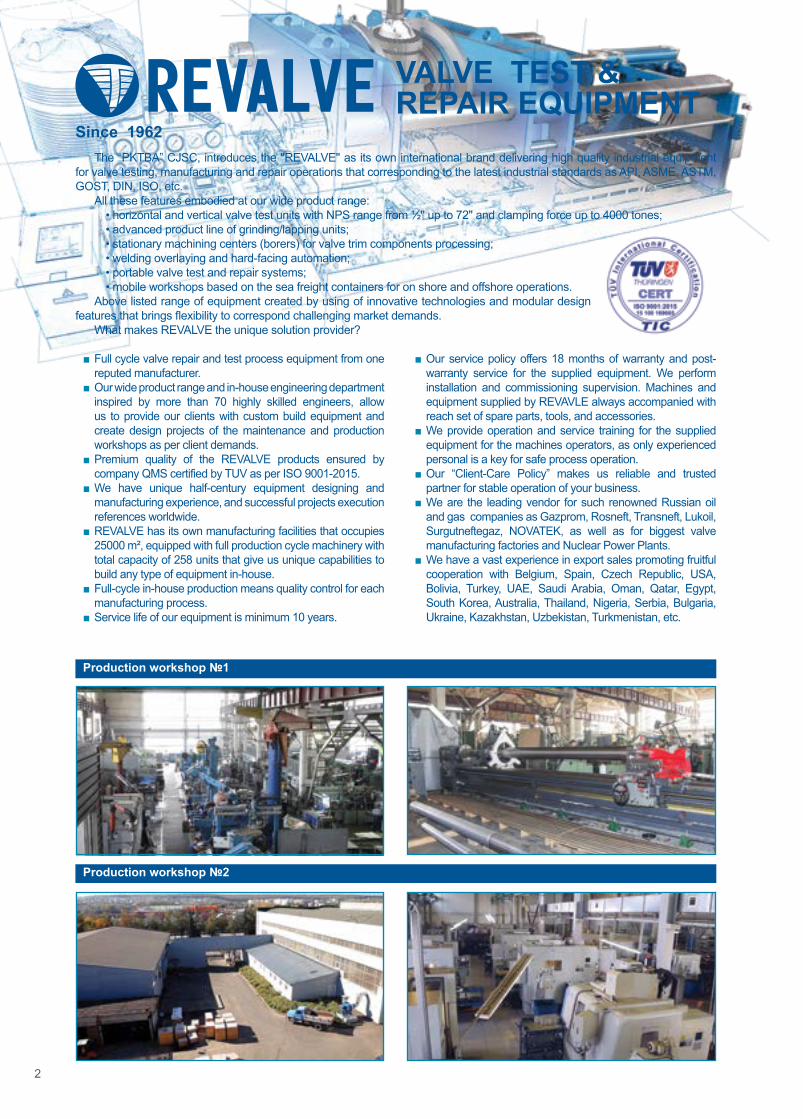
Production workshop №1
Production workshop №2
2
The “PKTBA” CJSC, introduces the ''REVALVE'' as its own international brand delivering high quality industrial equipment for valve testing, manufacturing and repair operations that corresponding to the latest industrial standards as API, ASME, ASTM, GOST, DIN, ISO, etc.
All these features embodied at our wide product range:• horizontal and vertical valve test units with NPS range from ½'' up to 72'' and clamping force up to 4000 tones;• advanced product line of grinding/lapping units;• stationary machining centers (borers) for valve trim components processing;• welding overlaying and hard-facing automation;• portable valve test and repair systems;• mobile workshops based on the sea freight containers for on shore and offshore operations.
Above listed range of equipment created by using of innovative technologies and modular design features that brings flexibility to correspond challenging market demands.
What makes REVALVE the unique solution provider?
■ Full cycle valve repair and test process equipment from one reputed manufacturer.
■ Our wide product range and in-house engineering department inspired by more than 70 highly skilled engineers, allow us to provide our clients with custom build equipment and create design projects of the maintenance and production workshops as per client demands.
■ Premium quality of the REVALVE products ensured by company QMS certified by TUV as per ISO 9001-2015.
■ We have unique half-century equipment designing and manufacturing experience, and successful projects execution references worldwide.
■ REVALVE has its own manufacturing facilities that occupies 25000 m², equipped with full production cycle machinery with total capacity of 258 units that give us unique capabilities to build any type of equipment in-house.
■ Full-cycle in-house production means quality control for each manufacturing process.
■ Service life of our equipment is minimum 10 years.
■ Our service policy offers 18 months of warranty and post-warranty service for the supplied equipment. We perform installation and commissioning supervision. Machines and equipment supplied by REVAVLE always accompanied with reach set of spare parts, tools, and accessories.
■ We provide operation and service training for the supplied equipment for the machines operators, as only experienced personal is a key for safe process operation.
■ Our “Client-Care Policy” makes us reliable and trusted partner for stable operation of your business.
■ We are the leading vendor for such renowned Russian oil and gas companies as Gazprom, Rosneft, Transneft, Lukoil, Surgutneftegaz, NOVATEK, as well as for biggest valve manufacturing factories and Nuclear Power Plants.
■ We have a vast experience in export sales promoting fruitful cooperation with Belgium, Spain, Czech Republic, USA, Bolivia, Turkey, UAE, Saudi Arabia, Oman, Qatar, Egypt, South Korea, Australia, Thailand, Nigeria, Serbia, Bulgaria, Ukraine, Kazakhstan, Uzbekistan, Turkmenistan, etc.
Since 1962

3
CONTENTABOUT COMPANY 2EQUIPMENT FOR DISASSEMBLING-ASSEMBLING OF VALVES
RMR 8WELDING AUTOMATION
UN 10UNG-400-1300-800-KN 11USKSH 12UNG-900-1200-3000-KNV 13UNG-KNV 14
MACHINES FOR GRINDING AND LAPPINGSP 16
MACHINES AND TOOLING FOR LATHING (EDGE CUTTING)SR 17
MACHINES FOR GRINDING AND LAPPINGSPSH 18
PORTABLE MACHINES FOR REPAIR OF GATE, GLOBE & SAFETY VALVESPUR-KK-100, PUR-KP-150 20PUR-1, PUR-2 22PUR-5 23
MOBILE WORKSHOPS20ft truck-mounted testing workshop for shut off and control valves 2510ft offshore workshop for psv testing and minor repairing 2620ft onshore workshop for hp gas/liquid testing of shut off valves with pressure isolated operator room 27
EQUIPMENT FOR TESTING FOR SHUT-OFF & CONTROL VALVESHorizontal test benches
S-6-1400/4000, S-6-1400/3200, S-6-1400/2800 DN up to 1400 mm (56″) 29S-6-1200/2000, S-6-1050/1600, S-5-1050/1300 DN up to 1400 mm (56″) 30S-5-900/850, S-6-800/750, S-5-1000/600, S-5-600/500 DN up to 1400 mm (56″) 31S-5-600/350, S-5-500/250, S-6-600/160 DN up to 700 mm (28″) 32S-5-350/160, S-5-300/65, S-5-150/40 DN up to 400 mm (16″) 33S-5P-600/500 DN up to 600 mm (24″) 34S-5-80/6-5 DN up to 80 mm (3″) 36
Vertical test benchesS-3-800/160, S-3-600/220,S-3-600/160 DN up to 800 mm (32″) 39S-3-600/100, S-3-500/160, S-3-500/100, S-3-500/60 DN up to 600 mm (24″) 40S-3-400/60, S-3-400/40, S-3-300/40, S-3-250/15 DN up to 400 mm (16″) 41S-3-300/400 DN up to 400 mm (16″) 42
Tilting test benchesS-4-400/25, S-4-400/270, S-4-300/40 DN up to 400 mm (16″) 44
Control stationsPGS Control stations 46
Multi-station test benchesS-3-300/160-3, S-3-250/60-5 DN up to 300 mm (12″) 48
TEST BENCHES FOR TESTING AND ADJUSTMENT OF PRESSURE SAFETY AND VACUUM RELIEF VALVESS-1-400/60, S-1-400/40, S-1-300/40, S-1-250/15 DN up to 400 mm (16″) 51MP-SRV-40 DN up to 300 mm (12″) 54
Breather valves testing unit in the rangeS-1-600/100 DN up to 600 mm (24″) 57
Test bench for testing springs of safety valvesSI-25M DN up to 300 mm (12″) 58
Portable measuring systemsD-14-EX portable measuring systems 59
COMPLEX FOR TESTING WELLHEAD AND ANTI-BLOWOUT EQUIPMENTSI-PVO Complex for testing 60UNIT №1 DN up to 280 mm (11″) 62UNIT №4 DN up to 425 mm (17″) 63UNIT №5 DN up to 425 mm (17″) 64
OPTIONAL EQUIPMENTCRS Computer registration system 67UK Automated compressor units 68SOV Recycling water supply station 69VU Vacuum system 69B Safety fence 70SI-PRA Test unit 71BR, MIP-W, MIP-A Leakage measuring unit 71MG Hydraulic drive unit 72MSSH Muffler for high pressure PSV
gas testing 72OUR CERTIFICATES 73CONTACT 73

Pipeline valve to repair1
Grinding and lapping of sealing surfaces
7
Disassembling and detection of defects
3
Tooling of sealing surfaces6
Testing of pipeline valve for strength, density, gate and environmental leakage
9
Tooling of sealing surfaces4
Washing and cleaning of pipeline valve
2
Painting and drying10
Welding of sealing surfaces5
Assembling of pipeline valve8
Pipeline valve are ready for use
11
4
THE GENERAL TECHNOLOGICAL SCHEME
The choice should be based on both the tested and repaired valve parameters and the characteristics of the repair and testing equipment itself:
• no axial compression (deformation) of the body during the tests;• pipeline valve type;• nominal bore (DN) and operating pressure (PN);• max/min valve body sizes;• valve connection type (BW, RF, RTJ, etc.);• test medium (water, air, nitrogen, oil, etc.);• valve position during the tests (horizontal / vertical / inclined / immersion);• specify compliance with test standard;• computer-aided measurements, parameter recording and test reports;• equipment capacity per shift;• number of operating personnel.
HOW TO MAKE PROPER CHOICE OF REPAIR AND TEST EQUIPMENT:

5
OUR TEAMThe result of continuous and creative work of several generations of our employees brought REVALVE to the leader
position in the industry. Up to date the REVALVE employs over than 800 highly educated specialists.
The commercial department is focused on a best customer service and accompanies the contract from the moment of the inquiry receiving up to the putting equipment into operation.
More than 70 talented engineers of our designing department are creating a design of the latest versions of the equipment, as well as special customized editions of equipment.
Supreme quality of our products achieved by using a professional software package such as three-dimensional modeling system Compass-3D, Solid Works and integrated automatic design system Altium Designer, which help us to reduce cost, improve product quality and accelerate the production cycle.
DESIGNING DEPARTMENT

6
QUALITY CONTROLOur QMS system has been certified as per latest edition of international QMS standard ISO 9001. All manufactured
products are tested under the overload conditions, according to the program and test procedures. Testing process is takes place in the safety bulletproof enclosure, which ensures safety of operating personnel.
Quality control has always been an essential element at every stage of manufacturing. All the outsourced parts and materials undergo 100% incoming control.
At the REVALVE all parts used in the production cycle are tracked by using the bar-coding system, which provides identification and traceability of each component of the products during manufacturing process. For the dimension control of machined parts we are using traditional measurement devices and ABERLINK coordinate measuring machine.
Our product range complies with national and international standards and is certified in accordance with requirements of EN 60204-1, EN ISO 12100, EN 2006/42/EC, EN 2004/108/EC, EN 2006/95/EC, and supplied with CE marking and declaration of conformity with EU requirements.
PRODUCTION CYCLEThe product range of REVALVE goes through all technological stages of manufacturing and constantly updated and
upgraded. Our in house production base is equipped with more than 200 units of the most modern equipment and CNC machining centers.
■ Raw material section of the workshop provides cutting of the round bars and profiled metal by semi-automatic belt-type cutting machines. As well as cutting of rolled and sheet metals achieved by CNC gas-oxygen torch cutting center.
■ Heat treatment parts are carried out in batch-type and shaft furnaces.■ Mechanical processing workshop performs fabricating of a threaded screws and gear wheels. All of the machining
operation is made on the high-duty machines.■ Operations of welding and surfaces overlaying, by carbon and alloy steels, non-ferrous metals and alloys are carried
out by highly qualified and certificated specialists.■ Before paint coating, equipment parts are cleared from rust and slag in the shot-blasting camera. ■ Painting section equipped with brand new heat drying camera, which provides a supreme quality of the paint coating.■ Assembling of the equipment is carried out in the shortest terms.

АвстралияАзербайджанБеларусьБельгияБоливияБолгарияВьетнамВенгрияЕгипетИндияИспанияИракИран КатарКазахстанКувейтМонголия
МьянмаНигерияОАЭОманРоссияРумынияСербияСШАСаудовская АравияТайландТуркменистанТурцияУзбекистанУкраинаФранцияЧехияЮжная Корея
7
WARRANTY AND AFTER SALES SERVICEOur service policy offers 18 months of warranty and post-warranty service for the supplied equipment.
Our company attaches the utmost importance to appropriate training of future operators of the equipment to ensure safe operation and maintenance of supplied equipment.
The REVALVE is a client oriented company and our customer care policy based on a long term partnership with our esteemed clients. REVALVE service department is always ready to perform immediate after sale service of supplied equipment.
The REVALVE ordered equipment is always fitted out with spare parts, tools, and accessories.
Through the decades REVALVE supplies products to the largest enterprises of Russia, CIS, Europe, Africa and South-East Asia.
Cooperating with REVALVE is the guarantee of reliable and safe operation of your business!
PROJECT ENGINEERING OF VALVE REPAIR AND TESTING FACILITIESWith REVALVE machines and know-how based on more than 55 years history of successful projects execution, we
can offer our customers cutting edge technologies by leveraging REVALVE’s knowledge base and our vast and varied experience in valve repair and testing equipment manufacturing and valve servicing solutions.
The REVALVE has the unique advantage of being the only valve repair and testing equipment manufacturer capable to provide the know-how, required for setting up a valve repair and testing workshop with all required equipment from one manufacture.
Our leadership in this field in more than 55 years of machine manufacturing experience, engineering and realization of valve repair and testing workshops projects for a broad range of industry sectors worldwide.
The REVALVE engineering services offers a complete solution for:1. Selection of equipment as per customer operation requirements.2. Workshop general processes.3. Equipment layout and foundation plan for equipment installation.4. Power and source supply engineering.5. Manufacturing of valves overhauling equipment.6. Engineering of turnkey workshop projects.7. Installation start up and training of equipment operators.8. Customized equipment engineering and manufacturing.
More than 70 highly qualified engineers of REVALVE are always ready to support our esteemed clients at the initial project stage, with our vast variety of engineering service packages, to ensure project implementation from its beginning to installation and start up of equipment.
Our commitment is improving of long term, safe and reliable operation of valve maintenance facilities at the end users sites.

UPG Rail trolley
8
RMRWORK STATION FOR VALVES ASSEMBLING/DISASSEMBLINGDN 15...1200 ММ
PURPOSE:• RMR-4, RMR-5 - disassembling and assembling of the
wedge, stop, control, and shut-off valves.• RMR-4-1 - disassembling and assembling and
performing preliminary pneumatic tests of the wedge, stop, control, and shut-off valves at a pressure of up to 6 bar (90 psi).
• RMR-6 - disassembling and assembling of the wedge and parallel-seat gate valve.
• RMR-PPK - disassembling and assembling of the safety valves.
• RMR-SH - disassembling and assembling of the slab gate valves.
• RMR-AFK - disassembling and assembling of the wellhead valves (Cross-type Christmas Tree).
• UPG - unit is designed for nuts unscrewing, screwing, and cutting (where it is impossible to unscrew).
OPTIONAL:
ADVANTAGES: ■ RMR is a set of accessory equipment to ensure fast and efficient disassembly and assembly of the pipeline valves.
■ The work bench with lockers, safety screen and lamp (1). ■ The bench for disassembly and assembly of the pipeline valves DN 15...300 mm (½…12″) and safety valves (2).
■ For convenience, the bench can be adjusted by height. ■ The bench for disassembly and assembly of the pipeline valves with nominal bore DN 300...600 mm (12…24″) ( 3).
■ For convenience, the bench is equipped with a ladder (4). ■ The bench for preliminary pneumatic tests of the pipeline valves DN 50...300 (½…12″) mm (5).
■ Rack under the oil station (6). ■ The stand with swinging boom, balance beam, replaceable screwdrivers and air preparation unit (7).
■ The hydraulic press for pressing-in (pressing-out) of bush sleeves of the gate valves (8).
■ The device for compressing the disk springs of the gate valves (9).
■ The drilling machine for repair jobs (10). ■ The vice for disassembly and assembly of the pipeline valves with nominal bore DN 15...40 mm (½…1 ½″) (11).
■ The stand with pneumatic screwdriver for installation and fixing of the Christmas Tree valves (12).
■ The height-adjusted movable support (13). ■ The hydraulic crane with load-carrying capacity 500 kg (14). ■ Each work station delivery set includes a fitting tool kit (15), rechargeable flashlight (16), and the first aid kit (16).
■ The stand for safety valves disassembly/assembly (17). ■ The bench for disassembly and assembly of the pipeline valves DN 700...1200 mm (28…48″) (18). For convenience, the bench is equipped with a repair site (19).
SPECIFICATIONS:Model Usable range DN, mm (″) Weight, kgRMR-4 15…300 (½...12) 502RMR-4-1 50…350 (2...14) 1305RMR-5 15…600 (½...24) 813RMR-6 700...1200 (28…48) 3800RMR-PPK 15…300 (½...12) 492RMR-SH 65, 80 (2½, 3) 1280RMR-AFK 65 (2½) 370
10 16 1
11
9
15

9
RMRWORK STATION FOR VALVES ASSEMBLING/DISASSEMBLINGDN 15...1200 ММ
COMPLETE SET:COMPLETE SET RMR-4 RMR-4-1 RMR-5 RMR-6 RMR-PPK RMR-SH RMR-AFKWork bench with lockers and safety screen (1) + + + + + +Bench (2) + + + +Bench (3) +Ladder (4) +Bench for preliminary pneumatic tests up to 6 bar (90 psi) (5) +Rack under the oil station (6) +Stand with swinging zigzag boom and pneumatic screwdriver (7) + + + + +Hydraulic press (8) +Device for compressing the disk springs of the gate valves (9). +Bench drilling machine (10) + + + + + +Vice (11) + + + + + +Stand (12) +Movable support (13) +Hydraulic crane (14) +Fitting tool kit (15) + + + + + + +Rechargeable flashlight (16) + + + + + +First aid kit (16) + + + + + + +Stand for safety valves disassembly/assembly (17) +Bench for disassembly/assembly of the wedge and parallel-seat gate valve (18)
+
Repair site (19) +
17
12
14
13
8
19
18
5
2
4
7
6
3

10
PURPOSE:• automated hardfacing/overlaying of pipeline parts and elements with
diameter from 50 up to 1200 mm (2...48") with or without electrode oscillation with submerged arc process or in an atmosphere of shielding gases (MIG/MAG processes) with full wire.
UNMACHINES FOR HARDFACING/OVERLAYING OF PIPELINE VALVES PARTSDN 50...1200 MM (2…48″)
ADVANTAGES: ■ The machines are fitted out with forced cooling of the welding unit and a set of water-cooled welding heads.
■ The electrode oscillating mechanism allows to increase the width of the overlayed seam up to 60 mm (2⅜").
■ Advanced construction of rotator allows to fix overlaid workpiece in three coordinates (tilt angle and position along the x and y axes).
■ Machines control system are based on industrial controller thus allowing operator to set hardfacing/overlaying parameters (oscillation amplitude, amplitude velocity, number of faceplate revolutions, and length of welding seam) through a touch screen control panel.
■ The unit is equipped with remote controller. ■ Time for readjustment from "gas" to flux" – not more than 10 min.
■ The set of spare parts includes a set of tools, wearing parts kit and first aid kit.
■ Welding zone backlighting. ■ The machines allow to perform hardfacing/overlaying of internal cylindrical surfaces and welding of girth welding seams in horizontal plane (overlaying of sealing rings, welding of flanges).*
■ The machines allow to reach a hardness of surfacing of 60 HRC and above.**
Weld pad
SPECIFICATIONS:Parameter UN-1 UN-2 UN-3
G F G F G FValve range, DN, mm (″) 50…300 (2...12) 50…600 (2...24) 300…1200 (12...48)Faceplate rotation speed, rpm 0,08...4,5 0,0125...1,25Tilt angle of the table, degrees 0...10Arc protection method gas (flux)Power supply, V/Hz 400/50 (480/60*)Welding current, А up to 600Electrode-wire diameter, mm (″) 1…1,6
(0,039...0,063)2…5
(0,079...0,197)1…1,6
(0,039...0,063)2…5
(0,079...0,197)1…1,6
(0,039...0,063)2…5
(0,079...0,197)Wire feed rate, m/h (in/h) 100…1200
(3937...47244)50…400
(1969...15748)100…1200
(3937...47244)50…400
(1969...15748)100…1200
(3937...47244)50…400
(1969...15748)Capacity, kg/h up to 5 up to 15 up to 5 up to 15 up to 5 up to 15Overall dimensions, mm (″) 1735x1015x3495
(68x40x137)1735x1015x3495
(68x40x137)3900х1800х4300
(156x72x170)Weight (machine/power source/control panel), kg
1120/240/60 1250/240/60 4100/240/60
* Upon customer request.** While using appropriate welding materials.

11
PURPOSE:• automated hardfacing/overlaying of shafts, spindles
and rods with diameter of up to 400 mm (16") with consumable electrode in an atmosphere of shielding gases (MIG/MAG/TIG* processes).
ADVANTAGES: ■ The machine is completed with forced cooling welding head and bended water-cooled burner for welding of fillet welds.
■ The machine allows hardfacing/overlaying of cylindrical workpieces with length up to 1250 mm (49").
■ The control system of the machine is implemented on the basis of industrial controller, which allows the operator to set the parameters of welding (range of oscillations, velocity of the oscillations, number of the faceplate revolutions, length of overlaying etc.) on the touch screen of control panel and to perform welding process in automatic mode.
■ Electrode oscillating mechanism provides greater performance of the hardfacing/overlaying process.
■ The machine allows to perform hardfacing/overlaying of cylindrical surfaces and welding of girth seams with automatic filling of the cutting edge.
■ The machine can be equipped with an additional (second) welding head to provide its greater performance.
SPECIFICATIONS:Parameter UNG-400-1300-800-KNRange of workpiece diameters, mm (″) 25...400 (1...16)Maximum weight of welded workpiece, kg 800Maximum length of the welded area, mm (″) 1000 (39)Maximum length of installed workpiece, mm (″) 1300 (51)Vertical travel of welding head, mm (″) 180 (7)*Horizontal travel of welding head, mm (″) 1300 (51)Welded workpiece rotation speed, rpm (continuously adjustable) 0,05...3Horizontal travel of welding head along welding seam, mm (″) ±50 (±2)Tailstock displacement, mm (″) 1300 (51)Amount of the quill movement, mm (″) 40 (1,6)Arc protection method gasCore wire diameter, mm (″) 1,0; 1,2; 1,6 (0,039; 0.047; 0,069)Rated welding current at 100% duty cycle (40 ° C), A 420Power supply, V/Hz 400/50Overall dimensions (machine/power supply unit) (LxWxH), mm (″) 2400х1725х2100/1100х455х1000 (94x68x83/44x18x40)Weight (machine/power supply unit), kg 1040/129
* Upon customer request.
UNG-400-1300-800-KNMACHINE FOR HARDFACING/OVERLAYING OF ROTATING BODIES

12
PURPOSE:• girth seam welding of pipeline parts with diameter from
15 up to 1400 mm (½ ... 56") with MIG/MAG process.
USKSHWELDING UNITS FOR GIRTH SEAM WELDING OF PIPELINE PARTSDN 15...1400 ММ (½…56″)
ADVANTAGES: ■ Simultaneous operation of two welding heads provides high performance of the unit.
■ Standard set of the units includes: rotator, gantry, two welding heads and two welders.
■ Tilting rotator face-plate. ■ Continuous adjustment of welding speed. ■ Control systems of the units are based on industrial controller, thus allowing operator to set welding parameters (welding speed, number of faceplate revolutions etc.) while using touch sensitive control panel.
■ The welding units can be optionally completed with the following accessories:*• flux recovery system (for “F” version);• tactile and optical tracking system;• electrode oscillating mechanism;• water recycling station (SOV);• video control system;• idle roller bed.
■ Simplicity and ease of operation.
SPECIFICATIONS:Parameter USKSH-1G USKSH-2G(F) USKSH-3G(F) USKSH-4FNominal internal diameter of welded valves (DN), mm (″)
15...125(½...5)
150...350(6...14)
300...700(12...28)
700...1400(28...56)
Load capacity including the device, kg 500 2000 10000 30000Welding head number, pcs 2Arc protection gas gas (flux) flux
Diameter of electrode wire, mm (″) 1,0; 1,2; 1,6(0,039; 0,047; 0,069)
1,0; 1,2; 1,6 (2...5)(0,039; 0.047; 0,069)
(0,079...0,2)
1,2; 1,6 (2...5)(0,047; 0,069) (0,079...0,2)
2...5(0,079...0,2)
Rated welding current, at 100% duty cycle, A 350 420 (600) 420(1000) 1000Overall dimensions (LxWxH), mm (″)
2150х2000х2600 (85х79х102)
2500х2200х2800(98х86х110)
3000х2500х3100 (118х98х122)
8150х7000х6000 (321х275х236)
* Upon customer request.
USKSH-2G
USKSH-4F

13
UNG-900-1200-3000-KNVAUTOMATED SYSTEM FOR BALL VALVE TRIM COMPONENTS CLADDING WITH OPTIONAL DEVICES FOR BALL VALVE BODY CIRCULAR WELDING DN 50…600 MM (2…24″)
PURPOSE:• automatic GTAW cladding (overlaying) of ball, trim
components surfaces of the ball valves.
ADVANTAGES: ■ Machine implies using a variety of hardfacing/overlaying methods of the metal layers. Such, as: submerged gas-shielded hardfacing/overlaying with wire electrode, submerged hardfacing/overlaying with tape electrode, and also plasma powder hardfacing/overlaying. Broad range of mentioned variants provides flexibility in the equipment application for various technical tasks.
■ Width of hardfacing/overlaying can reach 60...90 mm (2"...3") after one pass. That leads to significant increase in hardfacing/overlaying productivity.
■ Completely programmable course of the torch movement relative to the overlayed plug minimizes the influence of human factor on the welding result.
■ Optionally: systems of video surveillance and storage of data received during the welding process.
■ Application of high-precision slideways, modules of linear movement, ball screws allow to increase frequency of coordinate movement.
SPECIFICATIONS: Parameter UNG-900-1200-3000-KNVMaximum weight of processed parts, kg 2000Internal diameters of processed parts, mm (″) 50…600 (2...24)External diameters of processed parts, mm (″) up to 900 (35)Maximum length of processed parts , mm (″) up to 1000 (39)Welding current at 100%, А 350
Overall dimensions (LxWxH), mm (″) 5100 х 2500 х 4500(200x98x177)
Weight, kg 5000

14
PURPOSE:• automated hardfacing/overlaying of the external and internal
surfaces of cylinders with consumable electrode in an atmosphere of shielding gas or by flux-cored wire (MIG/MAG).
UNG-KNVMACHINES FOR HARDFACING/OVERLAYING OF CYLINDERS
ADVANTAGES: ■ Compact size. ■ The control systems of the machines allows to program the unit to perform hardfacing/overlaying of several types of parts.
■ The hardfacing/overlaying process may consist of several passes with different overlaying rate, the presence of transverse oscillation, different oscillation parameters (range, speed etc.).
■ Automation of hardfacing/overlaying process provides higher quality of the final result, excluding human factor.
■ Availability of flat surfaces hardfacing/overlaying. ■ Minimum internal diameter of overlayed workpiece is 16 mm (½ ″) .
■ Water-cooled welding head.
UNG-750-400-400-KNV-А

15
UNG-KNVMACHINES FOR HARDFACING/OVERLAYING OF CYLINDERS
SPECIFICATIONS: Parameter UNG-750-400-400-KNV-А UNG-850-850-1000-KNVHorizontal travel of welding head, mm (″) 550 (22) 1400 (55)Travel of a welding head along “zenith”, mm (″) 100 (4) 100 (4)Vertical travel of a welding head, mm (″) 400 (16) 1000 (39)Rotator load capacity, kg 400 300Rotator faceplate rotation speed, rpm 0,05÷7 0,2÷5Tilt angle of a rotator faceplate, deg. 0÷50 -Electrode-wire diameter, mm (″) 1,6; 2,8 (0,069; 0,11) 1,0; 1,2; 1,6 (0,039; 0,047; 0,063)Rated welding current, at 100% duty cycle, A 420Welding current adjustment range, А 5÷450Range of welding voltage, V 15÷35 15÷31Arc protection method gasMaximum power consumption, kW 35 45Power supply, V/Hz 400/50Overall dimensions, (LxWxH), mm (″):- machine; 1800х1050х2665 (71x41x105) 2295х1508х2845 (90x59x112)- power source. 1100х455х950 (44x18x37) 1100х455х1000 (43x18x39)Weight (machine/power source), kg 970/125 1220/129
UNG-850-850-1000-KNV

16
SPFLAT LAPPING (POLISHING) MACHINES DN 50...600 ММ (2...24″)
PURPOSE:• machine is designed for lapping (polishing) of the
flat sealing surfaces of the gate valve wedges, valve spools, and сhristmas-tree wedges;
• special-configuration SP-600 is used for lapping the end-seal rings.
ADVANTAGES: ■ Each point of the lapped surface of the parts makes complex plane-parallel motion on the lapping-plate surface.
■ The machines are equipped with the polishing-compound supply device.
■ The spent compound is collected in a special tank.
■ The lapping time is automatically controlled by the timer. ■ The machines are equipped with the smooth start device with the lapping-plate speed adjustment.
■ The machines are designed so that the lapping disc can be adjusted during its operation.
SPECIFICATOIN:Parameter SP-1200 SP-600Nominal diameter of the valve, DN, mm (″) 50…600 (2...24) 15...150** / 50...150** (½...6** / 2...6)Lapping-plate diameter, mm (″) 1250 (49) 620 (24)Number of cartridges 3 / 1 3Internal diameter of the cartridges, mm (″) 550 / 830 (21 / 32) 266 (10)Machined-surface roughness, μm 0,08…0,1 0,08...0,1Machined-surface nonflatness (accuracy), mkm 0,6Lapping-plate speed, rpm 5…40 10...50Installed power, kW 8 4Electric power supply, V/Hz 400/50 (480/60*)Working pressure of network air, bar (psi) 6,3 (91) -Overall dimensions (LхWхH), mm (″) 1976х1645х1325 (78x64x52) 1160х916х990 (46x38x41)Weight, kg 2100 625
* Upon customer request.** Valve spools.
TYPES OF MACHINED PARTS:• wedges of the gate and christmas-tree valves;• valve (global valve) spools;• end-seal rings of the pumps;• other flat-surface parts.
LAPPING-PLATE DIAMETER: • SP-1200: Ø 1250 mm (49″).
Approximately, DN 50…600 mm (2...24″) for the wedges of the gate valves, and DN 40…200 mm (2...8″) for the spools of the valves.
• SP-600: Ø 620 mm (24″). For the wedges of the gate valves DN 50…150 mm (2...6″).
SP-1200
SP-600

17
SR-1200
SRSPECIALIZED BORING MACHINE FOR MECHANICAL TREATMENT OF VALVE TRIM COMPONENTS DN 50…1200 MM (2...48″)
ADVANTAGES: ■ An advanced high performance machines with automated continuous control system.
■ Precise cutting and a wide range of technological functions create conditions for its versatile application thus providing treatment of both seal faces of the valve body as well as a flanges at a single placement on the bench.
■ CNC control system provides continuous machine control at 4 controlled axes (X, Y, Z, and W) and provides automated tilted positioning of the table, allowing treatment of seal faces of the fittings with different angles of a wedge chamber.
■ Implementation of placing and clamping devices provides quick placement of the valves and fittings to the machine table.
PURPOSE:• treatment (drilling, boring, milling) of pipeline valves, including
treatment of main-line and medium sized flanges, seal faces of bodies and gate wedges, flanges and welding ends edges for welding of DN up to 1200 mm (48″).
TREATED ITEMS:• wedge gate valves.
SR-800
SPECIFICATIONS:Parameter SR-1200 SR-800Range of diameters of treated products, mm (″) 600...1200 (24...48) 50...800 (2...32)Diameter of carrier spindle, mm (″) 130 (5) -Cone cavity of the carrier spindle metric - 80 -Travers displacement of table, mm (″) 2000 (79) ±100 (4)Radial support travers, mm (″) 250 (10) 100 (4)Vertical travel of spindle head, mm (″) 1800 (78) 1200 (47)Tilt angle of the table, degrees - ±12Securing face of the table, mm (″) 1800х1600 (71х63) 1000х1200 (39х47)Maximal weight of treated detail, kg (lbs) 10000 (22046) 2000 (4409)Total power consumption, kW 15 27,5Electric power supply, V/Hz 400/50Weight, kg 29300 12500

18
SPSHMACHINES FOR GRINDING & LAPPING OF THE PIPELINE VALVESDN 15...1000 MM (½...40″)
PURPOSE:• machines are designed for grinding and lapping of the flat
sealing surfaces of the housings and wedges of the gate valves, housings and spools of the stop valves (globe valves), safety valves and other flat surfaces.
TYPE OF VALVE: • gate valve;• globe valve;• safety valve.*
DN OF VALVE: Stationary units:
• SPSH-600-N: DN 50…600 mm (2...24″);• SPSH-1000-N: DN 300…1000 mm (12...40″).
Unit with two tilting tables:• SPSH-600-NN: DN 50…600 mm (2...24″).
Table base units:• SPSH-300-NN: DN 15…300 mm (½...12″);• SPSH-300-VV: DN 15…300 mm (½ ...12″).
ADVANTAGES: ■ The tilted table with adjustable tilt angle simplifies the installation procedure and allows machining of sealing surfaces at various tilt angles.
■ The coordinate device ensures the part installation by three coordinates (tilt angle and positioning with respect to the x and y axes).
■ To make installation procedure of workpiece more simple the column can turn on 290° relatively its base.
■ Digital indication of spindle rotational speed is provided. ■ The tool drawer unit allows to store replaceable accessories.
■ Uniform lapping plate and the adapter with eccentric allows to achieve high flatness of the surface.
■ Machines allow to conduct processing of valve parts on the first of the tables and to execute installation work and valve fastening on the second one (SPSH-600-NN, SPSH-300-NN, SPSH-300-VV).
■ Rotating table with adjustable axially offset is serving to increase the capacity of sealing surfaces treatment process (SPSH-300-VV).
■ Lathe three-jaw chuck allows to install the valve bodies and spools of small size (SPSH-300-VV).
SPSH-1000-N
* Upon customer request.

19
SPSH-600-N
SPSHMACHINES FOR GRINDING & LAPPING OF THE PIPELINE VALVESDN 15...1000 MM (½...40″)
SPSH-300-VV
SPECIFICATIONS: Parameter SPSH-1000-N SPSH-600-N SPSH-600-NN SPSH-300-NN SPSH-300-VV
Usable range, DN, mm (″) 300…1000(12...40)
50…600(2...24)
15…300(½...12)
Maximum diameter of the mounted valve flange, mm (″) 1255 (50) 890 (36) 500 (19)
Maximum face-to-face length of the mounted valve, mm (″) 1750 (69) 1150 (46) 700 (27)
Maximum weight of the mounted part, kg 2500 1000 500
Dimensions of the table working surface, mm (″) 1200х1200 (48x48) 900х900 (36x36) 500х500
(19х19) Ø 500 (19)
Tilt angle of the table, degrees 0…12Spindle rotation speed adjustment steplessSpindle rotation speed, rpm 10…150 14…200 10…240Machined surface roughness, μm 0,2…0,4Installed power, kW 2,0 2,45 2,0 3Power supply, V/Hz 400/50
Overall dimensions (LхWхH), mm (″) 2175х1550х3520(86x61x138)
1630х1640х3130(64x64x123)
2500х900х3025(98x41x119)
1716х1178х2588(67х48х102)
Weight (with tooling package), kg 3100 1420 2120 1200

20
COMPLETE SET:• professional pneumatic (Atlas Copco) and/or electric (Bosch) and/or battery (Metabo) drives (E);• device for mounting on the middle flange and machining the gate valve wedges (PUR-1, PUR-1-2, PUR-2);• stand for spool machining (PUR-5);• multi-function installation device (D);• replaceable grinding and lapping discs;• set of self-adhesive grinding wheels;• air preparation unit with a sleeve for compressed air supply;• carrying case (C);• set of spindles with the abrasive wheels based on electrocorundum;• set of spindles coated with the boron nitride.
ADVANTAGES: ■ Grinding and lapping of the sealing surfaces of the trim directly in the pipeline without dismantling the valves from the pipeline.
■ Small weight of the unit makes it convenient for use in hard-to-reach locations.
■ The quality is achieved due to design of the working head and the mandrel, which generate complex plane parallel motion of the tool across the processed surface.
■ The set includes the wedge processing unit, replaceable discs for grinding and lapping, and a tool storage box.
■ To ensure more reliable operation, the complete set of pneumatic drive includes air preparation unit.
■ Grinding wheels on the basis of the CBN and electrocorundum ensure high productivity of the process for removing the workpiece material and have a high resistance to wear. This reduces the time of grinding and lapping, extends the life of the lapping surface.
PORTABLE MACHINES FOR REPAIR OF GATE, GLOBE & SAFETY VALVES
PURPOSE:• portable machine is designed for grinding and lapping of the sealing
surfaces of the gate valve trim and wedges, globe valve and safety valve trim without their dismantling from the pipeline.
MACHINED-SURFACE TYPES: • sealing surfaces of the gate valve trim and wedges, safety and globe
valve trim and spools.
E
D
C
KP-150

21
SPECIFICATIONS:Parameter GLOBE AND SAFETY VALVES
PUR-KK-100 PUR-KP-150Nominal diameter of machined valves, DN (") 8...100 mm (5/16...4″) 8...150 mm (5/16...6″) Maximum depth of the machined surface (distance from valve axis to the valve actuator flange end), mm
330 (13) 260 (10)
Pneumatic-driven machineMaximum disc RPM 1300 1300Drive power on 6,3 bar pressure, kW 0,7 0,7Air consumption, l/min 1000 1000Air drive pressure, bar 6,3 6,3
Machine with non-accumulator electric drive (wired)Maximum disc RPM (1st gear/ 2nd gear) 1000/2800 1000/2800Power consumption, kW 1,2 1,2Drive torque, N m (1st gear/ 2nd gear) 33,0/13,0 33,0/13,0Power supply, V/Hz 220/50 220/50
Machine with accumulator electric drive (wireless)Maximum disc RPM (1st gear/ 2nd gear) 500/1700 500/1700Drive torque, N m (1st gear/ 2nd gear) 24,0/11,0 24,0/11,0Weight of the machine (w/o packing), kg 22 10Packed weight, kg 27,5 22
PUR-KK-100, PUR-KP-150PORTABLE MACHINE FOR GRINDING AND LAPPING OF GLOBE & SAFETY VALVESDN 8...150 MM (⁵/16...6")

22
PUR-1, PUR-1-2, PUR-2PORTABLE MACHINE FOR GRINDING AND LAPPING OF GATE VALVESDN 50...1000 MM (2...40")
SPECIFICATION:
ParameterGATE VALVES
PUR-1 PUR-1-2 PUR-2Usable range, DN, mm (″) 50…250 (2...10) 80..450 (3...18) 200…600 (8...24)Immersion depth - T, mm (″) 635 (25) 1000 (40)Minimum size - А, mm (″) 40 (2) 45 (2) 87 (3)Electric drive:- power consumption, kW; 1,3 1,6- supply voltage, V. 220 (110*)Pneumatic drive:- power, kW; 0,83 1,17- air flow rate, m³/min (gl/min); 1,6 (423)- compressed-air working pressure, bar (psi). 6,3 (91)Weight, kg:- the heaviest mounted assembly; 13,6 16 22- set. 49 140 190
* Upon customer request.

PUR-5PORTABLE MACHINE FOR GRINDING & LAPPING OF GLOBE & SAFETY VALVESDN 32...200 MM (1¼...8")
23
SPECIFICATIONS:
ParameterGLOBE AND SAFETY VALVES
PUR-5
Usable range, DN, mm (″) 32...200 mm (1¼...8″)(25...200 mm (1...8″) for safety valve)
Electric drive:- power consumption, kW; 1,3- supply voltage, V. 220 (110*)Pneumatic drive:- power, kW; 0,83- air flow rate, m³/min (gl/min); 1,6 (423)- compressed-air working pressure, bar (psi). 6,3 (91)Maximum immersion depth into the valve housing, mm (″) 200 (8)Weight, kg:- the heaviest mounted assembly; 7- set (with pneumatic and electric drive). 60
* Upon customer request.

24
AVAILABLE FUNCTIONS OF THE WORKSHOPS:1. Disassembling/assembling of the valves.2. Washing/sandblasting of the valve parts.3. Testing of shut-off and control valves:• shell test acc. to API 598, API 6D, ISO 5208 etc.;• seat leakage test (cavities A to B, B to A) acc. to API 598, API 6D, ISO 5208 etc.;• backseat test acc. to API 598, API 6D, ISO 5208 etc.;• DBB/DIB test acc. to API 598, API 6D;• control valve seat leakage test, acc. to ANSI FCI 70.2, IEC 60534-4, EN 1349 etc.
4. Testing of pressure safety valves:• set pressure definition acc. to API 526, ASME Section VIII, API RP 576;• reseat pressure definition acc. to API 526, ASME Section VIII, API RP 576;• seat leakage test acc. to API 527.
5. Test reports forming.6. Grinding and lapping of sealing surfaces.7. Minor machining of the valve parts.
FOR CUSTOMER CONVENIENCE, WORKSHOP CAN BE EQUIPPED WITH:1. Jib or overhead crane 0,5 ton or 1 ton capacity.2. Heating, ventilating and air conditioning (HVAC system).3. Armored wall between operator and testing room with door interlock.4. Pressure isolated operator room.5. Remote video control (CCTV).6. Various furniture (wardrobe, chairs, table etc.).7. Doors or gates on the sides of the workshop.8. Portable on-site PSV testing unit.9. Portable grinding and lapping unit.
WORKSHOPS ARE BASED ON:• 10ft sea container;• 20ft sea container (dry-cube and high-cube);• 40ft sea container (dry-cube and high-cube).
UPON REQUEST, WORKSHOPS ARE CERTIFIED FOR:• CSC for easy transportation;• DNV GL 2.7-1 for offshore use;• ATEX for hazardous areas use (only for container itself, not for equipment inside it).
WORKSHOPS ARE DESIGNED FOR VARIOUS CLIMATE ZONES FROM -55 TO +50 C°
MOBILE WORKSHOPS
PURPOSE:• Ready-to-use mobile workshops based on offshore
containers are highly useful for maintaining of valves on the end-user site or on the offshore platforms during a shutdown or if a regular on call repair is required.
• Modular design of mobile workshops allows to adopt them as per customer requirements and climate conditions. Workshops lineup allows to solve all kind of issues with valves overhauling at sites such as high pressure testing, calibration and maintenance of different kind of valves.
CONFORMED WITH STANDARD: API 526, API 527, API 598, ANCI FCI 70-2 (Class II-VI), DNV GL 2.7-1, ASME Section VIII, API RP 576,IEC 60534-4, EN 1349, API 6D, ISO 5208, etc.

25
COMPLETE SET:1. Clamping system for PSV up to DN 300 mm (12").2. Control station.3. Horizontal clamping system for shut-off and control valves up to DN 250 mm (10").4. Portable machine for grinding and lapping.5. Work station for valves assembling/ disassembling DN 300 mm (12").6. Valve washing/cleaning machines.7. Compressor unit.8. Diesel generator.9. Jib/overhead crane.
20FT TRUCK-MOUNTED TESTING WORKSHOPFOR SHUT OFF & CONTROL VALVES
MM-TR 20
1 2 3 4 8
9
5 6
7

26
COMPLETE SET:1. Clamping system for PSV up to DN 300 mm (12").2. Control station.3. Computer registration system.4. Portable machine for grinding and lapping.5. Work station for valves assembling / disassembling DN 300 mm (12").6. Jib crane.7. Safety fence.
10FT OFFSHORE WORKSHOPFOR PSV TESTING AND MINOR REPAIRING
1 27 3
45
5
6
MM-T 10

27
COMPLETE SET:1. Horizontal clamping system for shut-off and control valves up to DN 250 mm (10").2. Control station.3. Computer registration system.4. Armored wall with door.5. Jib crane.6. Remote video control (CCTV).7. Storage units.
20FT ONSHORE WORKSHOPFOR HP GAS/LIQUID TESTING OF SHUT OFF VALVES WITH PRESSURE ISOLATED OPERATOR ROOM
1
2
3
4
5
6
6
6
7
7
7
MM-T 20

28
CRS
p. 64
PGS
p. 46
UK
p. 66
SOV
p. 67
VU
p. 67
B, SVN
p. 68
EQUIPMENT FOR TESTINGHORIZONTAL TEST BENCHES FOR HYDRAULIC AND PNEUMATIC TESTING
OF SHUT OFF & CONTROL VALVES
PURPOSE: • shell test acc. to API 598, API 6D, ISO 5208 etc.;• seat leakage test (cavities A to B, B to A) acc. to API 598, API 6D, ISO 5208 etc.;• backseat test acc. to API 598, API 6D, ISO 5208 etc.;• DBB/DIB test acc. to API 598, API 6D;• control valve seat leakage test, acc. to ANSI FCI 70.2, IEC 60534-4, EN 1349 etc.
TESTED VALVES: • gate valves;• ball valves;• butterfly valves;• check valves;• plug valves;• control valves.
ADVANTAGES: ■ Clamping of tested valve is provided by hydraulic cylinder. Optionally test bench can be equipped with proportional clamping control system, which excludes axial compression applied to the valve body during clamping by hydraulic cylinder, during high pressure testing.*
■ Clamping unit can be provided with radial sealing type or self-sealing adapters.*
■ Two-sided gate sealing during tests does not require the tested valve rearrangement, which significantly reduces the test time.
■ The bench is equipped with a special system for air removal from the tested valve, which improves safety, productivity, reliability of the obtained data, and obviates the need for additional air drain.*
■ The bench is equipped with the water-collection tray with stainless steel tank.*
■ Test preparation time is significantly reduced by using the high-pressure quick-connect hoses.
■ The bench is quickly adjusted to face-to-face dimensions of valve by using the hydraulically or electrically driven cross-head.
■ The patented design of the self-sealing adapters exclude axial compression during the tests, which ensures the test reliability, protects the valves against deformation, and extends the valve life.*
■ All water-wetted parts are corrosion-proof. ■ The bench can be equipped with replaceable sealing adapters.*
■ Increased-diameter hoses reduce the time of the valve filling with the test medium.
■ Test bench can be equipped with valve lifting platforms for valve positioning and support during testing.*
* Upon customer request.
CONNECTION TYPE:• flanged (according to ASME B 16.5, ASME B 16.47, GOST 12815 etc.);• welded ends (according to ASME B 16.25, GOST 16037, etc.);*• set of sealing adapters available.*
DEPENDENCE OF THRUST FORCE (T) ON VALVE CHARACTERISTICS:DN, mm
(")class
10(⅜)
15(½)
20(¾)
25(1)
32(1 ¼)
40(1 ½)
50(2)
65(2 ½)
80(3)
100(4)
125(5)
150(6)
200(8)
250(10)
300(12)
350(14)
400(16)
500(20)
600(24)
700(28)
750(30)
800(32)
900(36)
1000(40)
1050(42)
1200(48)
1250(50)
1300(52)
1400(56)
cl.150 15 15 15 15 15 15 15 15 15 15 15 15 15 40 40 40 65 100 100 160 160 250 350 350 350 500 500 500 500cl.300 15 15 15 15 15 15 15 15 15 15 15 40 40 65 65 100 100 220 250 350 500 500 600 750 750 1100 1100 1100 1300cl.600 15 15 15 15 15 15 15 15 15 40 40 40 65 100 160 220 220 350 500 750 750 850 1100 1300 1600 2000 2000 2800 2800cl.900 15 15 15 15 15 15 15 15 15 40 40 65 100 160 220 250 350 600 750 1100 1100 1300 1600 2000 2800 2800 3200 3200 4000cl.1500 15 15 15 15 15 15 15 40 40 65 100 100 160 220 350 500 600 850 1300 1600 2000 2800 2800 3200 4000cl.2500 15 15 15 15 15 15 40 40 65 100 160 160 250 350 600 750 1100 1600 2000 2800 3200 4000
Note: Required tones of clamping force for valve shell test with test pressure 1.5 times exiding nominal. Parameters based on face sealing of RF flanged valves.
SI-PRA BR
p. 69
MIP-W
p. 69p. 69
OPTIONAL:

29
S-6-1400/4000, S-6-1400/3200, S-6-1400/2800TEST BENCHES FOR SHUT OFF & CONTROL VALVES DN 400...1400 MM (16...56″)
SPECIFICATIONS:Parameter S-6-1400/4000 S-6-1400/3200 S-6-1400/2800Maximum clamping force, t 4000 3200 2800Min./max. distance between the moving and stationary cross-heads, mm (″) 800/3400 (32/134) 800/3400 (32/134) 600/3400 (24/134)Distance between the columns, mm (″) 2950 (115) 2620 (103)
Overall dimensions (LхWхH), mm (″) 8500х4200х3000 (334х165х118)
8000х4000х2900 (315х157х114)
7800х3800х2900 (307х149х114)
Weight, kg 80000 70000 60000
* Maximum diameter for wedge gate valves (except ball valves).
S-6-1400/4000Maximum test pressure, bar (psi)
cl.150...900 cl.1500 cl.2500DN, mm
(″)235
(3400)305
(4400)395
(5700)435
(6300)530
(7600)630
(9100)600...800 (24..32)
900 (36) #1000 (40)1050 (42)1200 (48)1400 (56)
S-6-1400/3200Maximum test pressure, bar (psi)cl.150...600 cl.900 cl.1500 cl.2500
DN, mm(″)
185(2600)
240(3400)
315(4500)
345(5000)
420(6000)
595(8600)
630(9100)
500...700 (20...28)800 (32) #900 (36)
1000 (40) #1050 (42)1200 (48)1400 (56)
S-6-1400/2800Maximum test pressure, bar (psi)
cl.150...600 cl.900 cl.1500 cl.2500DN, mm
(″)160
(2300)210
(3000)275
(4000)305
(4400)375
(5400)520
(7500)630
(9100)400...700 (16...28)
800 (32)900 (36)
1000 (40)1050 (42)1200 (48) #
1400 (56)*
Maximum test Pressure can be higner by use of inner Radial seal adapters.#

30
S-6-1200/2000, S-6-1050/1600, S-5-1050/1300TEST BENCHES FOR SHUT OFF & CONTROL VALVES DN 150...1400 MM (6...56″)
Maximum test Pressure can be higner by use of inner Radial seal adapters.#
SPECIFICATIONS:Parameter S-6-1200/2000 S-6-1050/1600 S-5-1050/1300Maximum clamping force, t 2000 1600 1300Min./max. distance between the moving and stationary cross-heads, mm (″)
600/3400 (23/134) 600/3400 (23/134) 400/2600 (16/102)
Distance between the columns, mm (″) 2500 (98) 2000 (78) 1750 (69)
Overall dimensions (LхWхH), mm (″) 7500х3700х2200 (259x145x86)
7000х3000х2000 (276x118x79)
7000х3000х2000 (276x118x79)
Weight, kg 38000 34000 30000
* Maximum diameter for wedge gate valves (except ball valves).
S-6-1200/2000Maximum test pressure, bar (psi)cl.150...300 cl.600 cl.900 cl.1500 cl.2500
DN, mm(″)
115(1600)
150(2100)
195(2800)
215(3100)
265(3800)
370(5300)
480(6900)
630(9100)
400...600 (16...24)700 (28)800 (32)900 (36)
1000 (40) #1050 (42) # #
1200 (48)*1400 (56)*
S-6-1050/1600Maximum test pressure, bar (psi)
cl.150...300 cl.600 cl.900 cl.1500 cl.2500DN, mm
(″)90
(1300)120
(1700)155
(2200)170
(2400)210
(3000)295
(4200)385
(5500)520
(7500)630
(9100)400...500 (16...20)
600 (24)700 (28)800 (32)900 (36) #
1000 (40)1050 (42)
1200 (48)*1400 (56)*
S-5-1050/1300Maximum test pressure, bar (psi)
cl.150...300 cl.600 cl.900 cl.1500 cl.2500DN, mm
(″)95
(1300)125
(1800)140
(2000)170
(2400)240
(3400)310
(4400)420
(6000)600
(8700)630
(9100)150...400 (6...16)
500 (20) #600 (24)700 (28)800 (32)900 (36)
1000 (40) #1050 (42) # #
1200 (48)*

31
S-5-900/850, S-6-800/750, S-5-1000/600, S-5-600/500TEST BENCHES FOR SHUT OFF & CONTROL VALVES DN 100...1400 MM (4...56″)
Maximum test Pressure can be higner by use of inner Radial seal adapters.#
S-6-800/750 Maximum test pressure, bar (psi)
cl.150...300 cl.600 cl.900 cl.1500 cl.2500 DN, mm
(″)80
(1100)95
(1300)140
(2000)180
(2600)240
(3400)345
(5000)530
(7600)630
(9100)150...350 (6...14)
400 (16)500 (20) #600 (24)700 (28)800 (32) #
900 (36)*1000 (40)*
SPECIFICATIONS:Parameter S-5-900/850 S-6-800/750 S-5-1000/600 S-5-600/500Maximum clamping force, t 850 750 600 500Min./max. distance between the moving and stationary cross-heads, mm (″) 400/2300 (15/90) 220/2800 (8/110) 170/2800 (6/110) 170/2150 (7/85)
Distance between the columns, mm (″) 1532 (60) 1620 (64) 1675 (66) 1120 (44)
Overall dimensions (LхWхH), mm (″) 5700х2200х2000 (224x86x78)
5500х2000х2000 (216x78x78)
6000х2500х2150 (236x98x84)
4145х1890х1980 (163x74x78)
Weight, kg 24000 18000 16000 8000
* Maximum diameter for wedge gate valves (except ball valves).
S-5-900/850Maximum test pressure, bar (psi)
cl.150...300 cl.600 cl.900 cl.1500 cl.2500DN, mm
(″)90
(1300)110
(1500)155
(2200)205
(2900)275
(3900)390
(5600)600
(8700)630
(9100)200...350 (8...14)
400 (16) #500 (20)600 (24)700 (28) #800 (32)900 (36)
1000 (40)*
S-5-1000/600 Maximum test pressure, bar (psi)
cl.150 cl.300 cl.600 cl.900 cl.1500 cl.2500DN, мм 40 50 60 65 75 110 150 195 275 425 555 630
100...300 (4...12)350 (14)400 (16)500 (20)600 (24)700 (28)800 (32)900 (36)
1000 (40) #1050 (41)*1200 (47)*1400 (55)*
S-5-600/500Maximum test pressure, bar (psi)
cl.150...300 cl.600 cl.900 cl.1500 cl.2500DN, mm
(″)90
(1300)120
(1700)160
(2300)230
(3300)355
(5100)460
(6600)615
(8900)630
(9100)100...250 (4...10)
300 (12) #350 (14)400 (16) #500 (20)600 (24)
700 (28)*800 (32)*

32
SPECIFICATIONS:Parameter S-5-600/350 S-5-500/250 S-6-600/160Maximum clamping force, t (lbs) 350 250 160Min./max. distance between the moving and stationary cross-heads, mm (″) 150/2150 (6/85) 100/1300 (4/51) 66/1506 (2½ / 4)
Distance between the columns, mm (″) 1088 (43) 820 (32) 1004 (40)
Overall dimensions (LхWхH), mm (″) 3506х1805х1794 (138x71x70)
2802х1565х1640 (110x61x64)
4080х1445х1632(160x57x64)
Weight, kg 5296 3255 3756
* Maximum diameter for wedge gate valves (except ball valves).
S-5-600/350, S-5-500/250, S-6-600/160 TEST BENCHES FOR SHUT OFF & CONTROL VALVES DN 10...700 MM (⅜...28″)
S-5-600/350 Maximum test pressure, bar (psi)
cl.150...300 cl.600 cl.900 cl.1500 cl.2500 DN, mm
(″)80
(1100)110
(1500)160
(2300)245
(3500)320
(4600)430
(6200)630
(9100)50...250 (2...10)
300 (12)350 (14)400 (16)500 (20)600 (24)
700 (28)*
S-5-500/250Maximum test pressure, bar (psi)cl.150...300 cl.600 cl.900 cl.1500 cl.2500
DN, mm(″)
115(1600)
175(2500)
230(3300)
300(4300)
445(6400)
630(9100)
50...200 (2...8)250 (10)300 (12)350 (14)400 (16)500 (20)
Maximum test Pressure can be higner by use of inner Radial seal adapters.#
S-6-600/160Maximum test pressure, bar (psi)
cl.150...300 cl.600 cl.900 cl.1500 cl.2500 DN, mm
(″)50
(700)70
(1000)110
(1600)140
(2000)190
(2700)275
(4000)420
(6000)650
(9400)10...150 (⅜...6)
200 (8)250 (10)
300 (12)350 (14)400 (16) #
500 (20)
600 (24)

33
S-5-350/160, S-5-300/65, S-5-150/40TEST BENCHES FOR SHUT OFF & CONTROL VALVES DN 10...400 MM (⅜...16″)
SPECIFICATIONS:Parameter S-5-350/160 S-5-300/65 S-5-150/40Maximum clamping force, t 160 65 40Min./max. distance between the moving and stationary cross-heads, mm (″) 70/1100 (3/43) 60/900 (2/35) 40/600 (1/23)
Distance between the columns, mm (″) 579 (23) 525 (20) 337 (13)
Overall dimensions (LхWхH), mm (″) 3323х1295х1501 (131x51x59)
2714х901х1559 (107x35x61)
2014х692х1610 (79x27x63)
Weight, kg 2656 1675 885
* Maximum diameter for wedge gate valves (except ball valves).
S-5-350/160 Maximum test pressure, bar (psi)
cl.150...300 cl.600 cl.900 cl.1500 cl.2500DN, mm
(″)105
(1500)135
(1900)185
(2600)265
(3800)405
(5800)630
(9100)50...150 (2...6)
200 (8)250 (10)300 (12)350 (14) #
400 (16)*
S-5-300/65Maximum test pressure, bar (psi)
cl.150 cl.300 cl.600 cl.900 cl.1500 cl.2500DN, mm
(″)60
(800)80
(1100)115
(1600)175
(2500)315
(4500)465
(6700)630
(9100)10...100 (⅜...4)
125 (5)150 (6)200 (8)
250 (10)300 (12)
350 (14)*S-5-150/40Maximum test pressure, bar (psi)
cl.150...600 cl.900 cl.1500 cl.2500DN, mm
(″)195
(2800)285
(4100)410
(5900)630
(9100)10...80 (⅜...3)
100 (4)125 (5)150 (6) #
Maximum test Pressure can be higner by use of inner Radial seal adapters.#

34
PURPOSE:• submerged gas testing of pipeline valves;• testing of the body part materials for strength and
density (shell test);• gate tightness tests;• environmental leakage tests (including gland seals).
TESTED VALVES:• cryogenic valves; • gate valves;• ball valves;• butterfly valves;• check valves;• control valves;• globe valves.
CONNECTION TYPE:• flanged (according to ASME B 16.5, ASME B 16.47,
GOST 12815 etc.);• welded ends (according to ASME B 16.25, GOST
16037, etc.);*• threaded-ends for a small size valves;*• set of sealing adapters available.*
S-5P-600/500TEST BENCHES FOR SUBMERGED TESTING SHUT OFF & CONTROL VALVES DN 10...600 MM (⅜....24″)
ADVANTAGES: ■ Clamping of tested valve is provided by hydraulic cylinder. Optionally test bench can be equipped with proportional clamping control system, which excludes axial compression applied to the valve body during clamping by hydraulic cylinder, during high pressure testing.*
■ Clamping unit can be provided with radial sealing type or self-sealing adapters.*
■ Two-sided gate sealing during tests does not require the tested valve rearrangement, which significantly reduces the test time.
■ The bench is equipped with a special system for air removal from the tested valve, which improves safety, productivity, reliability of the obtained data, and obviates the need for additional air drain.*
■ The bench is equipped with the water-collection tray with stainless steel tank.*
■ Test preparation time is significantly reduced by using the high-pressure quick-connect hoses.
■ The bench is quickly adjusted to face-to-face dimensions of valve by using the hydraulically or electrically driven cross-head.
■ The patented design of the self-sealing adapters exclude axial compression during the tests, which ensures the test reliability, protects the valves against deformation, and extends the valve life.*
■ All water-wetted parts are corrosion-proof. ■ The bench can be equipped with replaceable sealing adapters.*
■ Increased-diameter hoses reduce the time of the valve filling with the test medium.
■ Test bench can be equipped with valve lifting platforms for valve positioning and support during testing.*
* Upon customer request.
CONFORMED WITH STANDARD: API 6D; API 598; DIN EN 12266;DIN 3230; ISO 5208; ASTM E 1003;GOST 33257, etc.
OPTIONAL:PGS
p. 46
CRS
p. 64
UK
p. 66
SI-PRA BR
p. 69
MIP-W
p. 69p. 69
SOV
p. 67
VU
p. 67
B, SVN
p. 68

35
S-5P-600/500TEST BENCHES FOR SUBMERGED TESTING SHUT OFF & CONTROL VALVES DN 10...600 MM (⅜....24″)
SPECIFICATIONS:Parameter S-5P-600/500Maximum clamping force, t 500Min./max. distance between the moving and stationary cross-heads, mm (″) 180/1850 (7/73)Distance between the columns, mm (″) 1300 (51)Power supply, V/Hz 400/50Motor power, kW 18 Overall dimensions (LхWхH), mm (″) 6720х3580х3270 (264х148х128)Weight, kg 12300
S-5P-600/500 Maximum test pressure, bar (psi)cl.150...600 cl.900 cl.1500 cl.2500
DN, mm(″)
160(2300)
230(3300)
355(5100)
460(6600)
615(8900)
630(9100)
10...250 (⅜...10)300 (12) #350 (14)400 (16) #500 (20)600 (24)
Maximum test Pressure can be higner by use of inner Radial seal adapters.#
36
PURPOSE:• submerged gas testing of pipeline valves; • testing of the body part materials for strength and
density (shell test);• gate tightness tests;• environmental leakage tests (including gland seals).
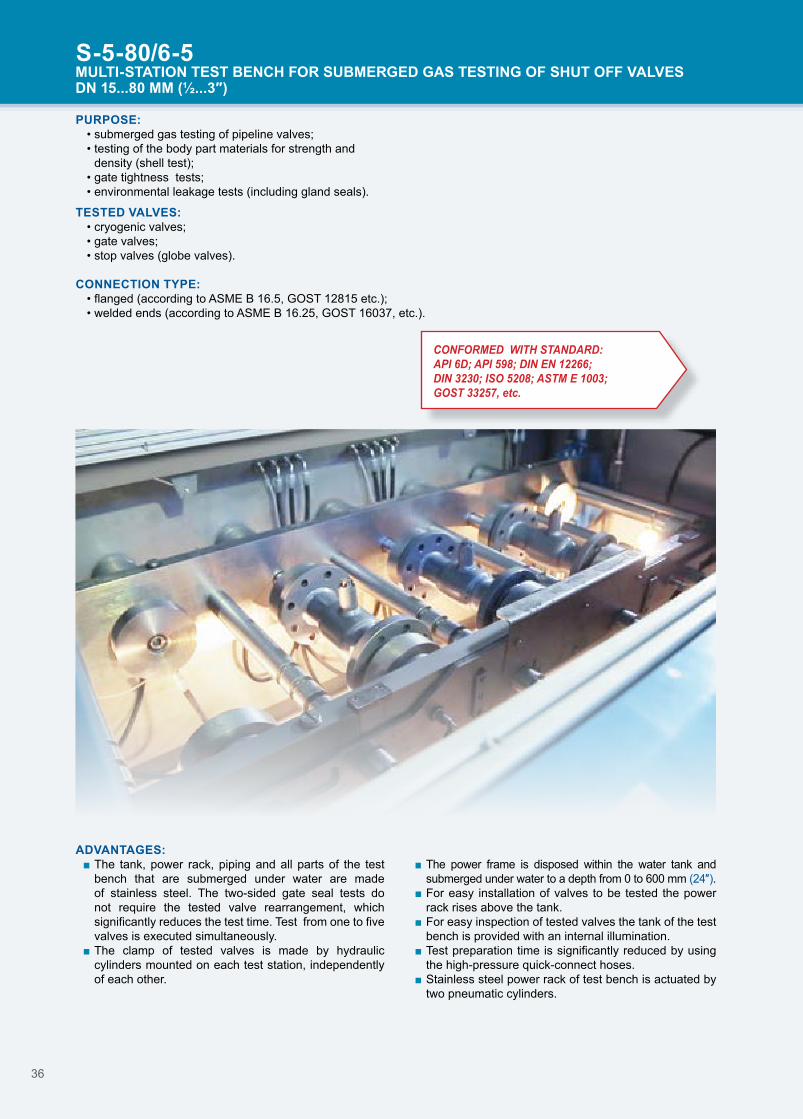
S-5-80/6-5MULTI-STATION TEST BENCH FOR SUBMERGED GAS TESTING OF SHUT OFF VALVESDN 15...80 MM (½...3″)
ADVANTAGES: ■ The tank, power rack, piping and all parts of the test bench that are submerged under water are made of stainless steel. The two-sided gate seal tests do not require the tested valve rearrangement, which significantly reduces the test time. Test from one to five valves is executed simultaneously.
■ The clamp of tested valves is made by hydraulic cylinders mounted on each test station, independently of each other.
■ The power frame is disposed within the water tank and submerged under water to a depth from 0 to 600 mm (24″).
■ For easy installation of valves to be tested the power rack rises above the tank.
■ For easy inspection of tested valves the tank of the test bench is provided with an internal illumination.
■ Test preparation time is significantly reduced by using the high-pressure quick-connect hoses.
■ Stainless steel power rack of test bench is actuated by two pneumatic cylinders.
TESTED VALVES: • cryogenic valves; • gate valves; • stop valves (globe valves).
CONNECTION TYPE:• flanged (according to ASME B 16.5, GOST 12815 etc.);• welded ends (according to ASME B 16.25, GOST 16037, etc.).
CONFORMED WITH STANDARD: API 6D; API 598; DIN EN 12266;DIN 3230; ISO 5208; ASTM E 1003;GOST 33257, etc.

37
S-5-80/6-5MULTI-STATION TEST BENCH FOR SUBMERGED GAS TESTING OF SHUT OFF VALVESDN 15...80 MM (½...3″)
SPECIFICATIONS:Parameter S-5-80/6-5Maximum clamping force of each test station, t 6Total maximal clamping force, t 30Min./max. distance between the moving and stationary cross-heads, mm (″) 115/510 (4/18)
Distance between the columns, mm (″) 270 (11)Power supply, V/Hz 400/50Overall dimensions (LхWхH), mm (″) 2730x1750x1370 (107х69х54)Weight, kg 2650
* Upon customer request.
Maximum test Pressure can be higner by use of inner Radial seal adapters.#
S-5-80/6-5Maximum test pressure, bar (psi)*
cl.150...300 cl.900 cl.1500 cl.2500DN, mm
(″)95
(1300)135
(1900)225
(3200)330
(4700)475
(6800)630
(9100)15...32 (½...1¼) #
40 (1½) #50 (2)
65 (2½)80 (3)

38
EQUIPMENT FOR TESTINGVERTICAL TEST BENCHES FOR HYDRAULIC AND PNEUMATIC TESTING
OF SHUT OFF & CONTROL VALVES
PURPOSE: Testing of shut-off and control valves:
• shell test acc. to API 598, API 6D, ISO 5208 etc.;• seat leakage test (cavities A to B, B to A) acc. to API 598, API 6D, ISO 5208 etc.;• backseat test acc. to API 598, API 6D, ISO 5208 etc.;• DBB/DIB test acc. to API 598, API 6D;• control valve seat leakage test, acc. to ANSI FCI 70.2, IEC 60534-4, EN 1349 etc.
TESTED VALVES:
• gate valves;• ball valves;• stop valves (globe valves);• check valves;• butterfly gates;• plug valves;• control valves.
CONNECTION TYPE:• flanged (according to ASME B 16.5, GOST 12815 etc.);• welded ends (according to ASME B 16.25, GOST 16037, etc.);• threaded-end;*• true union.*
ADVANTAGES: ■ Clamping of tested valve is provided by hydraulic cylinder. Optionally test bench can be equipped with proportional clamping control system, which excludes axial compression applied to the valve body during clamping by hydraulic cylinder, during high pressure testing.*
■ Two-sided gate sealing during tests does not require the tested valve rearrangement, which significantly reduces the test time.
■ The bench is equipped with the water-collection tray with stainless steel tank.*
■ Test preparation time is significantly reduced by using the high-pressure fast coupling hoses.
■ The bench is quickly adjusted to face-to-face dimensions of valve by using the electrically driven cross-head.
■ The patented design of the self-sealing adapters exclude axial compression during the tests, which ensures the test reliability, protects the valves against deformation, and extends the valve life.*
■ All water-wetted parts are corrosion-proof. ■ The bench can be equipped with replaceable sealing adapters.*
■ Increased-diameter hoses reduce the time of the valve filling with the test medium.
■ Turning upper cross-head is used to simplify the valve installation procedure before testing.
■ Test preparation time is significantly reduced by using the high-pressure quick-connect hoses.
■ Fast clamping and centering of the tested valve is ensured due to synchronized travel of the clamps.
■ Test bench allows visual detection of seat leakage point.
DEPENDENCE OF THRUST FORCE (T) ON VALVE CHARACTERISTICS:DN, мм
(")class
10(⅜)
15(½)
20(¾)
25(1)
32(1 ¼)
40(1 ½)
50(2)
65(2 ½)
80(3)
100(4)
125(5)
150(6)
200(8)
250(10)
300(12)
350(14)
400(16)
500(20)
600(24)
700(28)
750(30)
800(32)
cl.150 15 15 15 15 15 15 15 15 15 15 15 15 15 40 40 40 60 100 100 160 160 160cl.300 15 15 15 15 15 15 15 15 15 15 15 15 40 60 60 100 160 220cl.400 15 15 15 15 15 15 15 15 15 15 40 40 40 60 100 160 160 220cl.600 15 15 15 15 15 15 15 15 15 15 40 40 60 100 160 220 220cl.900 15 15 15 15 15 15 15 15 15 40 40 60 100 160 220cl.1500 15 15 15 15 15 15 15 40 40 40 60 100 160 220cl.2500 15 15 15 15 15 15 40 40 40 100 100 160
Note: Required tones of clamping force for valve shell test with test pressure 1.5 times exiding nominal. Parameters based on face sealing of RF flanged valves.
* Upon customer request.
OPTIONAL:PGS
p. 46
CRS
p. 64
UK
p. 66
SI-PRA BR
p. 69
MIP-W
p. 69p. 69
SOV
p. 67
VU
p. 67
B, SVN
p. 68

39
S-3-800/160, S-3-600/220, S-3-600/160 TEST BENCHES FOR SHUT OFF & CONTROL VALVES DN 10...800 MM (⅜...32″)
SPECIFICATIONS:Parameter S-3-800/160 S-3-600/220 S-3-600/160Maximum clamping force, t 160 220 160Min./max. diameter of the clamped flange, mm (″) 160/1020 (6/40) 160/910 (6/36) 90/840 (3/33)Maximum thickness of the clamped flange, mm (″) 94 (3) 115 (4) 94 (3)Min./max. distance between the moving and stationary cross-heads, mm (″) 80/1450 (3/57) 160/1445 (6/57) 90/1255 (4/50)
Distance between the columns, mm (″) 1150 (45) 970 (38) 900 (35)
Overall dimensions (LхWхH), mm (″) 1975х1700х4371 (78x67x176)
1745х1165х4505 (69x46x177)
1730х1640х3970 (68x64x156)
Weight, kg 4170 3815 3391
S-3-800/160Maximum test pressure, bar (psi)
- cl.150 cl.300 cl.600 cl.900 cl.1500 cl.2500DN, mm
(″)25
(300)35
(500)50
(700)70
(1000)110
(1500)145
(2100)190
(2800)275
(4000)420
(6100)630
(9100)10...150 (⅜...6)
200 (8)250 (10)300 (12) #350 (14)400 (16)500 (20)600 (24)700 (28)800 (32) #
S-3-600/220Maximum test pressure, bar (psi)
cl.150...300 cl.600 cl.900 cl.1500 cl.2500DN, mm
(″)70
(1000)100
(1500)150
(2200)200
(2900)265
(3900)380
(5500)580
(8500)630
(9100)50...150 (2...6)
200 (8) #250 (10)300 (12)350 (14) #400 (16)500 (20)600 (24)
S-3-600/160Maximum test pressure, bar (psi)
cl.150 cl.300 cl.600 cl.900 cl.1500 cl.2500DN, mm
(″)50
(700)70
(1000)110
(1600)145
(2100)190
(2800)270
(3900)400
(5800)630
(9100)50...150 (2...6)
200 (8)250 (10)300 (12) #350 (14)400 (16)500 (20)600 (24)
Maximum test Pressure can be higner by use of inner Radial seal adapters.#

40
S-3-600/100, S-3-500/160, S-3-500/100, S-3-500/60 TEST BENCHES FOR SHUT OFF & CONTROL VALVES DN 10...600 MM (⅜...24″)
SPECIFICATIONS:Parameter S-3-600/100 S-3-500/160 S-3-500/100 S-3-500/60Maximum clamping force, t 100 160 100 60Min./max. diameter of the clamped flange, mm (″) 90/840 (4/33) 90/730 (4/28) 90/730 (4/28) 90/730 (4/28)Maximum thickness of the clamped flange, mm (″) 115 (4) 94 (3) 115 (4)Min./max. distance between the moving and stationary cross-heads, mm (″) 80/1252 (3/49) 77/1146 (3/45) 110/1160 (4/45) 70/1000 (3/39)
Distance between the columns, mm (″) 900 (35) 750 (29) 770 (30) 775 (31)
Overall dimensions (LхWхH), mm (″) 1725х1405х3890 (68x55x153)
1485х1405х3707 (58x55x146)
1485х1395х3646 (58x55x143)
1350x1408x3095 (53x55x122)
Weight, kg 2683 3008 2457 1807
S-3-600/100Maximum test pressure, bar (psi)
cl.150 cl.300 cl.600 cl.900 cl.1500 cl.2500DN, mm
(″)30
(400)45
(600)70
(1000)90
(1300)120
(1700)170
(2500)265
(3800)450
(6500)630
(9100)10...125 (⅜...5)
150 (6)200 (8)
250 (10)300 (12)350 (14)400 (16)500 (20)600 (24)
S-3-500/160Maximum test pressure, bar (psi)
cl.150...300 cl.600 cl.900 cl.1500 cl.2500DN, mm
(″)70
(1000)110
(1300)145
(2100)190
(2800)270
(3900)400
(5800)630
(9100)10...150 (⅜...6)
200 (8)250 (10)300 (12) #350 (14)400 (16)500 (20)
S-3-500/100Maximum test pressure, bar (psi)
cl.150 cl.300 cl.600 cl.900 cl.1500 cl.2500
DN, mm(″)
45(600)
70(1000)
90(1300)
120(1700)
170(2500)
265(3800)
450(6500)
630(9100)
10...125 (⅜...5)150 (6)200 (8)
250 (10)300 (12)350 (14)400 (16)500 (20)
S-3-500/60Maximum test pressure, bar (psi)
cl.150 cl.300 cl.600 cl.900 cl.1500 cl.2500 DN, mm
(″)25
(300)40
(500)55
(700)70
(1000)100
(1500)150
(2200)280
(4000)400
(5800)600
(8700)630
(9100)10...80 (⅜...3)
100 (4) #125 (5)150 (6)200 (8)
250 (10)300 (12)350 (14)400 (16)500 (20)
Maximum test Pressure can be higner by use of inner Radial seal adapters.#

41
S-3-400/60, S-3-400/40, S-3-300/40, S-3-250/15 TEST BENCHES FOR SHUT OFF & CONTROL VALVES DN 10...400 MM (⅜... 16″)
SPECIFICATIONS:Parameter S-3-400/60 S-3-400/40 S-3-300/40 S-3-250/15Maximum clamping force, t 60 40 15Min./max. diameter of the clamped flange, mm (″) 90/580 (4/23) 90/460 (4/18)Maximum thickness of the clamped flange, mm (″) 115 (4)Min./max. distance between the moving and stationary cross-heads, mm (″) 70/1005 (2/40) 78/943 (3/37) 56/871 (2/34) 22/636 (1/25)
Distance between the columns, mm (″) 630 (25) 645 (25) 500 (19) 480 (19)
Overall dimensions (LхWхH), mm (″) 1212х1137х3055 (47x44x120)
1214х1034х2879 (47x40x113)
983х1068х2690 (38x42x106)
965х1068х2235 (38x42x88)
Weight, kg 1556 1082 860 631
S-3-400/60Maximum test pressure, bar (psi)
cl.150 cl.300 cl.600 cl.900 cl.1500 cl.2500DN, mm
(″)40
(500)55
(700)70
(1000)100
(1500)150
(2200)280
(4100)400
(5800)600
(8700)630
(9100)10...80 (⅜...3)
100 (4) #125 (5)150 (6)200 (8)
250 (10)300 (12)350 (14)400 (16)
S-3-400/40Maximum test pressure, bar (psi)
- cl.150 cl.300 cl.600 cl.900 cl.1500 cl.2500DN, mm
(″)25
(300)35
(500)45
(600)70
(1000)105
(1500)190
(2800)250
(3600)405
(5900)630
(9100)10...80 (⅜...3)
100 (4)125 (5)150 (6) #200 (8)
250 (10)300 (12)350 (14)400 (16) #
S-3-300/40Maximum test pressure, bar (psi)
cl.150 cl.300 cl.600 cl.900 cl.1500 cl.2500DN, mm
(″)45
(600)70
(1000)105
(1500)190
(2800)250
(3600)405
(5900)630
(9100)10...80 (⅜...3)
100 (4)125 (5)150 (6) #200 (8)
250 (10)300 (12) #
S-3-250/15Maximum test pressure, bar (psi)
- cl.150 cl.300 cl.600 cl.900 cl.1500 cl.2500 DN, mm
(″)25
(300)40
(500)70
(1000)105
(1500)150
(2200)240
(3500)330
(4800)540
(7800)630
(9100)10...40 (⅜...1½)
50 (2) #65 (2½) #
80 (3)100 (4)125 (5)150 (6)200 (8)
250 (10) #
Maximum test Pressure can be higner by use of inner Radial seal adapters.#

42
CRS
p. 64
OPTIONAL:PGS
p. 46
UK
p. 66
SOV
p. 67
VU
p. 67
B, SVN
p. 68
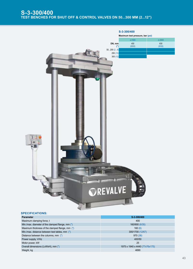
S-3-300/400TEST BENCHES FOR SHUT OFF & CONTROL VALVES DN 50...300 MM (2...12″)
PURPOSE:• shell test acc. to API 598, API 6D, ISO 5208 etc.;• seat leakage test (cavities A to B, B to A) acc. to API 598, API 6D, ISO 5208 etc.;• backseat test acc. to API 598, API 6D, ISO 5208 etc.;• DBB/DIB test acc. to API 598, API 6D;• control valve seat leakage test, acc. to ANSI FCI 70.2, IEC 60534-4, EN 1349 etc.
TESTED VALVES: • gate valves; • ball valves;• globe valves;• check valves;• butterfly gates;• plug valves.
CONNECTION TYPE:• flanged RF, FF, RTJ (according to ASME B 16.5, ASME 16.47 etc.);• BW (according to ASME B 16.25, etc.);• Flangeless (lug, wafer type).
SI-PRA BR
p. 69
MIP-W
p. 69p. 69
ADVANTAGES: ■ Adjustable valve testing position: valves intended to operate vertically are tested vertically, valves intended to use horizontally are tested horizontally;
■ Quicker valve mounting and centering because of three simultaneously moved claws
■ No airtraps during filling, the valve is filled vertically and then tilted to horizontal position
■ Possibility to observe sealing surface during leakage test (45 degrees tilted valve)
■ Clamping of tested valve is provided by hydraulic cylinder. Optionally test bench can be equipped with proportional clamping control system, which excludes axial compression applied to the valve body during clamping by hydraulic cylinder, during high pressure testing.
■ Two-sided gate sealing during tests does not require the tested valve rearrangement, which significantly reduces the test time.
■ The bench is equipped with the water-collection tray. ■ Test preparation time is significantly reduced by using the high-pressure fast coupling hoses.
■ The bench is quickly adjusted to face-to-face dimensions of valve by using the electrically driven cross-head.
■ All water-wetted parts are corrosion-proof. ■ Increased-diameter hoses reduce the time of the valve filling with the test medium.
43
SPECIFICATIONS:Parameter S-3-300/400Maximum clamping force, t 400Min./max. diameter of the clamped flange, mm (") 160/900 (6/35)Maximum thickness of the clamped flange, mm (") 160 (6)Min./max. distance between test tables, mm (") 300/1700 (12/67)Distance between the columns, mm (") 970 (38)Power supply, V/Hz 400/50Motor power, kW 25Overall dimensions (LхWхH), mm (″) 1975 х 1940 х 4440 (77х76х175)Weight, kg 4690
S-3-300/400TEST BENCHES FOR SHUT OFF & CONTROL VALVES DN 50...300 MM (2...12″)
S-3-300/400Maximum test pressure, bar (psi)
cl.1500 cl.2500 DN, mm
(″)450
(6500)630
(9100)50...200 (2...8)
250 (10)300 (12)

44
ADVANTAGES: ■ Adjustable valve testing position: valves intended to operate vertically are tested vertically, valves intended to use horizontally are tested horizontally;
■ Quicker valve mounting and centering because of three simultaneously moved claws.
■ No airtraps during filling, the valve is filled vertically and then tilted to horizontal position.
■ Possibility to observe sealing surface during leakage test (45 degrees tilted valve).
■ Clamping of tested valve is provided by hydraulic cylinder. Optionally test bench can be equipped with proportional clamping control system, which excludes axial compression applied to the valve body during clamping by hydraulic cylinder, during high pressure testing.
■ Two-sided gate sealing during tests does not require the tested valve rearrangement, which significantly reduces the test time.
■ The bench is equipped with the water-collection tray. ■ Test preparation time is significantly reduced by using the high-pressure fast coupling hoses.
■ The bench is quickly adjusted to face-to-face dimensions of valve by using the electrically driven cross-head.
■ All water-wetted parts are corrosion-proof. ■ Increased-diameter hoses reduce the time of the valve filling with the test medium.
PURPOSE:• shell test acc. to API 598, API 6D, ISO 5208 etc.;• seat leakage test (cavities A to B, B to A) acc. to API 598, API 6D, ISO 5208 etc.;• backseat test acc. to API 598, API 6D, ISO 5208 etc.;• DBB/DIB test acc. to API 598, API 6D;• control valve seat leakage test, acc. to ANSI FCI 70.2, IEC 60534-4, EN 1349 etc.
TESTED VALVES: • gate valves; • ball valves;• globe valves;• check valves;• butterfly gates;• plug valves.
CONNECTION TYPE:• flanged RF, FF, RTJ (according to ASME B 16.5, ASME 16.47 etc.);• BW (according to ASME B 16.25, etc.);• flangeless (lug, wafer type).
TILTING TEST BENCHESFOR HYDRAULIC AND PNEUMATIC TESTING OFF SHUT OFF & CONTROL VALVES
OPTIONAL:PGS
p. 46
CRS
p. 64
UK
p. 66
SI-PRA BR
p. 69
MIP-W
p. 69p. 69
SOV
p. 67
VU
p. 67
B, SVN
p. 68

45
S-4-400/25, S-4-400/270, S-4-300/40TEST BENCHES FOR SHUT OFF & CONTROL VALVES DN 15...400 MM (½...16″)
S-4-400/25 Maximum test pressure, bar (psi)
- - - cl.150 cl.300 cl.600 cl.900 cl.1500 DN, mm
(″)17
(600)23
(600)30
(600)45
(600)65
(1500)120
(2800)250
(4100)400
(5900)15...80 (½...3)
100 (4)150 (6)
200 (8)250 (10)300 (12)350 (14)
400 (16)
SPECIFICATIONS:Parameter S-4-400/25 S-4-400/270 S-4-300/40Maximum clamping force, t 25 270 40Min./max. diameter of the clamped flange, mm (″) 90/580 (3/23) 160/670 (6/26) 160/460 (6/18)Maximum thickness of the clamped flange, mm (″) 115 (4) 110 (4) 44 (2)Min./max. distance between test tables, mm (″) 70/1000 (2/39) 180/800 (7/31) 170/730 (7/29)Distance between the columns, mm (″) 645 (25) 1115 (44) 760 (30)Power supply, V/Hz 400/50Motor power, kW 5,5
Overall dimensions (LхWхH), mm (″) 3700 x 3000 x 2895 (145х118х114)
2000x2060x3370 (79х81х132)
1655x1038x2786 (65х41х110)
Weight, kg 3000 5500/2210 1320/470
S-4-400/270Maximum test pressure, bar (psi)
cl.150...600 cl.900 cl.1500 cl.2500 DN, mm
(″)190
(2700)245
(3500)330
(4700)485
(7000)630
(9100)50...200 (2...8)
250 (10)300 (12) #350 (14)400 (16)
S-4-300/40Maximum test pressure, bar (psi)
cl.150 cl.300 cl.600 cl.900 cl.1500 cl.2500 DN, mm
(″)45
(600)75
(1000)105
(1500)195
(2800)285
(4100)410
(5900)630
(9100)10...80 (⅜...3)
100 (4)125 (5)150 (6) #200 (8)
250 (10)300 (12)
Maximum test Pressure can be higner by use of inner Radial seal adapters.#

46
PGSCONTROL STATIONS
PURPOSE:• pressure source for hydraulic tests of valves and pressure vessels;• supplies as a control panel of the test bench;• as well as independent pressure source.
OPTIONS:• PGS-P edition is equipped with the automatic
proportional clamping control system. PLC controlled system allows to perform testing of valves in a safe mode excluding axial compression applied to the valve body during testing using automated proportional clamping pressure adjustment in hydraulic cylinder, relatively to testing pressure.
• PGS-M mobile version of control station, that allow to perform testing at sites (blind flanges are not included).
• PGS-A edition allow to perform testing of valves in automatic mode. Also can be provided with proportional clamping control system. The range of process automation should be negotiated and stated at the order stage in technical specification to the contract of supply.
FUNCTIONS: 1. Hydraulic test medium pressure up to 1600 bar (23200 psi).2. Continuous (stepless) pressure control for: - hydraulic tests 10...1600 bar (145…23200 psi); - pneumatic tests 0.5...10 bar (7…145 psi) (5...400 bar (72.5…5801 psi) upon customer request).*3. Smooth control of the test-bench hydraulic clamping cylinder.4. Automatic maintaining of achieved test pressure.5. Valve gate leakage measurement by the drop and bubble methods (see B).6. Control of the test process by the pressure-gage panel with the measurement accuracy of 1.0 % (0.6% as requested by customer).7. The PGS is equipped with sockets to connect additional calibration test gages with the required accuracy (see А).8. The PGS, can be connected to the CRS for recording of test data.
* Upon customer request.
Pressure up to 1600 bar (23200 psi)
PGS-A
B
C
A
F
E

47
COMPLETE SET:• pressure source unit with the bench control panel:
- 1 or 2 pneumohydraulic boosters (according to model);- monitoring, adjustment, and control equipment;
• air preparation unit;• preliminary and fine water filters (D);• pedal for the valve-clipping control during the test (Е);• air and water leakage control unit (В);• a set of high-pressure quick-connect hoses;• a set of spare parts, tools, and accessories;• safety fence (С);• embedded PKTBA-CRS (F).
PGSCONTROL STATIONS
ADVANTAGES: ■ The PGS control circuit uses pneumatically controlled gate elements. This releases the operator from opening and closing numerous needle valves and makes the unit control process simple and reliable.
■ The equipment has separate filling line to reduce the test preparation time.
■ For convenience, control of the hydraulic clamping cylinder of the test bench can be performed from the control panel and remote pedal (see E).
■ The PGS external connection diagram uses fast coupling joints with warranted operation life of 10,000 cycles, which significantly reduces the time required to complete preparation and final operations.
■ The compressed-air supply line has the air-preparation unit and ensures class 0 air supply even when the pneumatic network contains polluted air.
■ To extend the unit operation time, the PGS water input is equipped with a fine water filter (see D).
B A
D
PGS-M
PGS-P

48
MULTI-STATION TEST BENCHESFOR HYDRAULIC AND PNEUMATIC TESTING FOR SHUT OFF & CONTROL VALVES
PURPOSE: • shell test acc. to API 598, API 6D, ISO 5208 etc.;• seat leakage test (cavities A to B, B to A) acc. to API 598, API 6D, ISO 5208 etc.;• backseat test acc. to API 598, API 6D, ISO 5208 etc.;• DBB/DIB test acc. to API 598, API 6D;• control valve seat leakage test, acc. to ANSI FCI 70.2, IEC 60534-4, EN 1349 etc.
TESTED VALVES:
• gate valves; • globe valves;• check valves; • butterfly gates; • ball and plug valves.
CONNECTION TYPE:• flanged (according to ASME B 16.5, GOST 12815, etc.); • welded ends (according to ASME B 16.25, GOST16037, etc.).
ADVANTAGES: ■ Increased productivity due to simultaneous testing of multiple valves.
■ Testing in semi-automatic and automatic modes which affects the testing quality.
■ Digital flowmeters allows to check the leakage rate of valve on each station with leakage class automatic definition.
■ Axial load is minimized by using of self-sealing plugs; ■ All the wetted parts are made of stainless steel. ■ Two-side leakage test (A to B, B to A) without valve reinstallation (optional feature).
■ DBB/DIB tests are available for each station (optional feature)
■ Valve actuators are controlled remotely (optional feature).
■ Computerized registration system allows to create test reports for each station (optional feature).
■ Safety screen to improve operator safety (optional feature).
■ Remote video control (CCTV, optional feature).
CONFORMED WITH STANDARD: API 6D; API 598; DIN EN 12266;DIN 3230; ISO 5208; ASTM E 1003;GOST 33257, etc.
* Upon customer request.
DEPENDENCE OF THRUST FORCE (T) ON VALVE CHARACTERISTICS:DN, мм
(")class
10(⅜)
15(½)
20(¾)
25(1½)
32(1¼)
40(1 ½)
50(2)
65(2 ½)
80(3)
100(4)
125(5)
150(6)
200(8)
250(10)
300(12)
cl. 150
10 10 10 10 10 10 10 10 10 10 25 25 60 60 100
10 10 10 10 10 10 10 10 10 10 25 25 60 60 100
10 10 10 10 10 10 10 10 10 10 25 25 60 60 100
10 10 10 10 10 10 10 10 10 10 25 25 60 60 100
cl. 300 10 10 10 10 10 10 10 10 10 10 25 25 60 60 10
cl. 400 10 10 10 10 10 10 10 10 10 10 25 25 60 60 100
cl. 600 10 10 10 10 10 10 10 10 10 25 25 60 60 100 160
cl. 900 10 10 10 10 10 10 10 10 25 25 60 60 100 160
cl. 1500 10 10 10 10 10 10 25 25 60 60 60 100 160
cl. 2500 10 10 10 10 10 25 25 60 60 100 160 160
Note: Required tones of clamping force for valve shell test with test pressure 1.5 times exiding nominal. Parameters based on face sealing of RF flanged valves.
OPTIONAL:CRS
p. 64
SOV
p. 67
VU
p. 67
SI-PRA BR
p. 69
MIP-W
p. 69p. 69

49
SPECIFICATIONS: Parameter S-3-100/10-3 S-3-150/25-3 S-3-250/60-3 S-3-300/100-3 S-3-300/160-3 S-3-100/10-5 S-3-150/25-5 S-3-250/60-5Number of posts 3 5Maximal clamping force, t 3х12 3х25 3х62 3х104 3х160 5х12 5х25 5х62Min./max. diameter of the clamped flange, mm (″) 100 (4) 150 (6) 250 (10) 300 (12) 300 (12) 100 (4) 150 (6) 250 (10)
Max. construction reinforcement length, mm (″) 450 (18) 600 (24) 750 (30) 800 (32) 1000 (40) 450 (18) 600 (24) 750 (30)
Distance between the columns, mm (″) - 400 (16) 500 (20) 580 (22) 650 (25) - 400 (16) 500 (20)
Distance between axes of adjacent posts, mm (″) 300 (12) - - - - 300 (12) - -
S-3-250/60-5
S-3-300/160-3
S-3-300/160-3, S-3-250/60-5MULTI-STATION TEST BENCH FOR SHUT OFF & CONTROL VALVES DN 10...300 MM (⅜...12″)

50
TEST BENCHESFOR TESTING AND ADJUSTMENT OF PRESSURE SAFETY AND VACUUM RELIEF VALVES
PURPOSE: Test benches are designed for hydraulic and pneumatic testing of spring loaded, pilot-operated, and other types of PSVs with DN 10...400 mm (⅜...16''), breather (pressure vacuum relief) valves DN 50...500 mm (2...20'') according to the following standards:
• set pressure test according to API 526;• seat tightness test according to API 527;• breather (pressure vacuum relief) valves API RP 2000.
Advanced test system design, provides correspondence of the PSV test process to requirements of the following standards:
• API RP 576;• ISO 4126-1;• ASME BPVC Section VIII;• ASME PTC 25.
DEPENDENCE OF THRUST FORCE (TF) ON VALVE CHARACTERISTICS:DN, мм
(")class
10(⅜)
15(½)
40(1 ½)
50(2)
80(3)
100(4)
150(6)
200(8)
250(10)
300(12)
400(16)
cl.150 15 15 15 15 15 15 15 15 15 40 40cl.300 15 15 15 15 15 15 15 15 40 40cl.600 15 15 15 15 15 15 40 40 60cl.900 15 15 15 15 15 40 40 60cl.1500 15 15 15 15 40 40 60cl.2500 15 15 15 40 40 60
Note: Required tones of clamping force for valve shell test with test pressure 1.5 times exiding nominal. Parameters based on face sealing of RF flanged valves.
TESTED VALVES TYPES: • spring loaded PSVs;• pilot-operated PSVs;• breather (pressure vacuum relief) valves.
TESTED VALVE SIZES:• DN 50...500 mm (2...20") flanged breather valves;• DN 15...400 mm (½...16") flanged PSVs;• DN 10...50 mm (¼...2'') threaded PSVs.

51
S-1-400/60, S-1-400/40, S-1-300/40, S-1-250/15TEST BENCH FOR SAFETY VALVES DN 10...400 MM (⅜...16″)
SPECIFICATIONS:
ParameterS-1-400/60 S-1-400/40 S-1-300/40 S-1-250/15
3 claws 3 claws 2 claws 3 claws 3 clawsMaximum clamping force, t 60 40 15Tested valve sizes, mm (″) 10...400 (⅜...16) 10...300 (⅜...12) 10...250 (⅜...10)Min./max. diameter of the clamped flange, mm (″) 90/580 (4/23) 90/610 (4/24) 90/460 (4/18)
Maximum thickness of the clamped flange, mm (″) 115 (4)
Overall dimensions (LхWхH), mm (″)
1175х1315х970 (46x51x38)
1214х1034х990 (48x41x39)
1170х935х965 (46x37x38)
1048х1068х925 (41x42x36) 925x1070x925 (36x42x36)
Weight, kg 1050 607 538 481 370
CLAMPING UNIT
DESIGN FEATURES: ■ Clamping system design based on integrated high performance hydraulic cylinder, stainless steel base that serves as storage tank for hydraulic test medium. Clamping of valve need to be tested, provided by test table actuated by hydraulic cylinder and three synchronized claws thats centering and fastening of inlet PSV flange.
■ Increased inner diameter of test system tubing and high pressure hoses provides dynamic spool lifting during set pressure test, as well as smooth and accurate reseating, same time serves to avoid the seats surface damages while closing.
■ Use of special Nickel and Chrome coatings and stainless steel elements of clamping unit water wetted surfaces provides stable operation in hard environmental conditions with high level of humidity.
■ «Pockets» for set of sealing adapters storing. ■ Built-in stainless steel test fluid storage tank . ■ Adapters for PSV inlet flange face sealing for valves with DN 15...400 mm (½... 12'') of the following types: FF, SG, RF, LM, LG, RTJ as per ASME B 16.5.
■ Plugs for PSV outlet flange face sealing with fittings for quick connection of drop/bubble counter tubing.
OPTIONS:• Set of adapters with standard RTJ gasket for inlet
flange sealing, designed accord-ing to ASME B 16.5.• Sealing adapters for thread-type PSV sealing DN
15...50 mm (½...2'').• Safety fence for provision of operators safety in
accordance with HSE requirements available in several editions:
- surrounding (two sheets metal blocks) safety fence with bullet proof windows, gates safety locking device and remote operated video control system;- safety screen at control station for protection of operator's from splashes;- safety fence arrangement mounted around clamping unit.
• Portable muffler provides noise level reduction at PSVs outlet during pop testing.
• Test unit elements can be positioned on the mobile platform with forklift pockets for easier unit transportation to the end-users sites.
S-1-400/40
S-1-300/40
S-1-250/15
PSV test unit can be based on a several types of clamping systems, which clamping force and performance capabilities will be calculated according to PSV type, diameter and required pressure rating.

52
CONTROL STATIONTHE CONTROL STATION HAS MODULE CONSTRUCTION AND CAN BE EQUIPPED WITH THE FOLLOWING SYSTEMS ACCORDING TO THE CUSTOMER REQUIREMENTS:• High pressure hydraulic clamping control system. Mandatory system providing comfortable and quick operation of the clamping unit.• Pneumatic test system up to 400 bar (5800 psi). Test system allowing to test the most PSV's (according to API 526/527, up to class 1500) with gas/nitrogen test
mediums.System operation requires external compressed air/nitrogen source with maximum pressure up to 400 bar (5800 psi). Compressor unit or booster with accumulators available as an option.
• Hydraulic and pneumatic test system up to 400 bar (5800 psi). Test system allowing to test the most PSV's (according to API 526/527, up to class 1500) with liquid or gas/nitrogen test
mediums. System operation requires external compressed air/nitrogen source with maximum pressure up to 400 bar (5800 psi). Compressor unit or booster with accumulators available as an option.
• Pneumatic test system up to 690 bar (10000 psi). Optional system based on pneumatic-actuated booster. Used for gas testing of PSV up to class 2500 and higher.
Operation requires external compressed air/gas source with pressure up to 35 bar (500 psi).• Hydraulic test system up to 690 bar (10000 psi). Optional system used for hydraulic testing of PSV up to class 2500 and higher. Based on pneumatic-actuated
booster. Operation requires external compressed air/gas source with pressure up to 35 bar (500 psi).• Pneumatic and Hydraulic test system up to 690 bar (10000 psi). Optional system required for high pressure PSV testing with gas and liquid mediums. Combines both above-
mentioned test systems up to 690 bar (1000 psi).
TEST BENCHESFOR TESTING & ADJUSTMENT OF PRESSURE SAFETY & VACUUM RELIEF VALVES

53
TEST BENCHESFOR TESTING AND ADJUSTMENT OF PRESSURE SAFETY AND VACUUM RELIEF VALVES
DESIGN FEATURES: ■ Clamping system control is equipped with safety interlock that prevents tested valve unclamping while tested valve is under pressure higher than 1 bar.
■ Test process controlled by needle, regulating and isolation valves of world A-class manufacturers.
■ Test systems up to 400 bar (5800 psi) are equipped with additional test vessels for increasing of test line volume. Additional test medium volume provides dynamic spool lifting and precise determination of PSV set point, test line residual pressure, helps in accurate reseating point determination, saving PSV sealing surfaces from damages while reseating.
■ Equipment complies with following standards:ISO 4126-1, API RP 576, ASME BPVC Section VIII, which are establishing the requirements for the accuracy of the safety valve setting, and the ASME PTC 25 standard, which regulates the speed of the pressure gaining when 90% of the set pressure is reached.
■ Systems are equipped with additional lower pressure range gauges for more accurate test parameters measuring at low pressure testing. These pressure gauges are equipped with automatic shut-off devices to avoid pressure gauge damages while test pressure exceeds maximum stated test parameters.
■ To improve safety and avoid the risk of involuntary increasing of the test pressure, system control panel is equipped with a duplicate test line control button, to raise test pressure the operator shall hold the button pressed (two-handed control system)
■ Test medium, gas or liquid, can be selected by using switch at the control panel.
■ The control panel equipped with emergency stop button.
■ Control stations with hydraulic test systems are equipped with pneumatically driven pump for quick water filling of tested valve.
■ The control panel is equipped with protective screen with a large protective window of durable polycarbonate glass (Lexan or Makrolon).
■ Test mediums undergoes through fine filters, all water wetted parts are made of corrosion proof materials improving long service life of the test system.
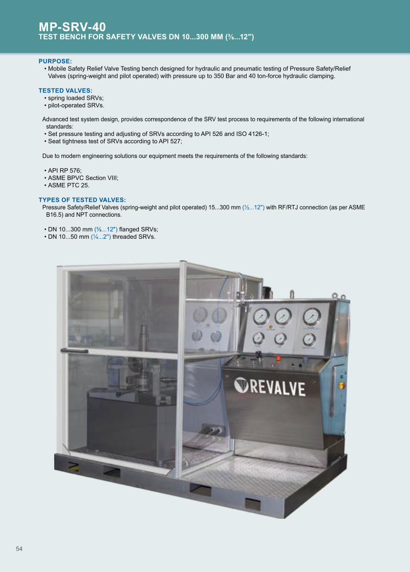
54
MP-SRV-40TEST BENCH FOR SAFETY VALVES DN 10...300 MM (⅜...12″)
PURPOSE: • Mobile Safety Relief Valve Testing bench designed for hydraulic and pneumatic testing of Pressure Safety/Relief
Valves (spring-weight and pilot operated) with pressure up to 350 Bar and 40 ton-force hydraulic clamping. TESTED VALVES:
• spring loaded SRVs;• pilot-operated SRVs.
Advanced test system design, provides correspondence of the SRV test process to requirements of the following international standards:
• Set pressure testing and adjusting of SRVs according to API 526 and ISO 4126-1;• Seat tightness test of SRVs according to API 527;
Due to modern engineering solutions our equipment meets the requirements of the following standards:
• API RP 576;• ASME BPVC Section VIII;• ASME PTC 25.
TYPES OF TESTED VALVES:Pressure Safety/Relief Valves (spring-weight and pilot operated) 15...300 mm (½...12'') with RF/RTJ connection (as per ASME
B16.5) and NPT connections.
• DN 10...300 mm (⅜...12″) flanged SRVs;• DN 10...50 mm (¼...2'') threaded SRVs.

55
MP-SRV-40TEST BENCH FOR SAFETY VALVES DN 10...300 MM (⅜...12″)
MP-SRV-40Maximum test pressure, bar (psi)
cl.150 cl.300 cl.600 cl.900 cl.1500DN, mm
(″)45
(600)70
(1000)105
(1500)190
(2800)350
(5100)10...100 (⅜...4)
150 (6)200 (8)
250 (10)300 (12)
SPECIFICATIONS:
ParameterMP-SRV-40
3 clawsMaximum clamping force, t 40Tested valve sizes, mm (″) 10...300 (⅜...12)Min./max. diameter of the clamped flange, mm (″) 90/460 (4/18)Maximum thickness of the clamped flange, mm (″) 125 (5)Overall dimensions (LхWхH), mm (″) 1050х1070х930 (41x42x36)Weight, kg 485
ADVANTAGES: ■ Clamping system design based on integrated high performance hydraulic cylinder, stainless steel base that serves as storage tank for hydraulic test medium. Clamping of valve need to be tested, provided by test table actuated by hydraulic cylinder and three synchronized claws that’s centering and fastening of inlet SRV flange.
■ Emergency stop button. In case of emergency and contingency by pressing the red button the pressure supply immediately stops protecting the operator, personnel and the tested valve. The tested unit stays clamped and stable, the testing pressure is released.
■ Safety interlock system. Unclamping automatically becomes impossible when a test pressure at the clamping station above 3 Bar so that yellow warning lamp indicates the presence of test pressure.
■ Two hand safety operation. To exclude the risk of unintended pressure increase during pneumatic, hydraulic testing and ensure the safety operation the station is equipped with a safety button.
■ Light signalization. Light signal on the control station automatically indicates that the valve is under pressure and respectively being deactivated when the pressure below 3 Bar.
■ Increased inner diameter of test system tubing and high-pressure hoses provides dynamic spool lifting during set pressure test, as well as smooth and accurate reseating same time serves to avoid the seats surface damages while closing.
■ Use of special Nickel and Chrome coatings and stainless steel elements of clamping unit water wetted surfaces provides stable operation in hard environmental conditions with high level of humidity.
■ «Pockets» for set of sealing adapters storing. ■ Built-in stainless steel test fluid storage tank. ■ Adapters for SRV inlet flange face sealing for valves with DN 15...400 mm (½...12'') of the following types: FF, SG, RF, LM, LG, RTJ as per ASME B 16.5.
■ Plugs for SRV outlet flange face sealing with fittings for quick connection of drop/bubble counter tubing.
OPTIONS:• Set of adapters with standard RTJ gasket for inlet
flange sealing, designed according to ASME B 16.5.• Sealing adapters for thread-type SRV sealing DN
15...50 mm (½ ... 2'').• Safety fence for provision of operators safety in
accordance with HSE requirements available in several editions:- surrounding (two sheets metal blocks) safety fence
with bullet proof windows, gates safety locking device and remote operated video control system;
- safety screen at control station for protection of operator's from splashes;
- strong and robust 4-side safety screen made of protective transparent 12 mm thick Lexan (polycarbonate) on a rigid metal base surrounding the clamping unit.
• Portable muffler provides noise level reduction at SRVs outlet during pop testing.
• Test unit elements can be positioned on the mobile platform with forklift pockets for easier unit transportation to the end-users sites.
• REVALVE can optionally provide the clamping unit with two claws that is able to perform testing most of SRV types.
• Computer Registration System is built-in to the control station for easy process operation and test monitor. Designed for continuous test data measuring and storing final reports as well as printing test protocols at workshop printer via Wi-Fi quick connection. Software package is customized and operator friendly so doesn't require special skills to launch and run the system. The package can be translated into the required native language upon request.
• Compressor unit. Serve for provision of the test system with constant supply of high-pressure air for valve test testing. The compressor unit consists of a piston-type compressor placed into the acoustic rigid cabinet and mounted on the base. There are pressure transmitter, pressure gauge and control panel are on the frame for an operator use. Storage cylinder area consists of 3 carbon steel rigid cylinders made of carbon steel fixed on the welded rack.

56
OPTIONS:• High pressure booster based gas test system with gas
accumulators.• High pressure compressor unit (air up to 400 bar/ 5800
psi) with compressed air accumulators up to 150 liters. • Compressed air saving system. Especially required
when customer needs to test a large number of valves within short time period without recharging vessels or compressed air accumulators.
• Computer Registration System. • CRS-based Semi-Automatic Test System. • Device for breather (pressure vacuum relief) valves
testing. Designed for mounting of pressure vent and breather valves DN 50...500 mm (2...20''). Control panel provides testing with overpressure up to 2 bar and vacuum depth of up to 500 mm (20'') of water column scale.
• Pressure vent and breather valves testing control system can be either integrated into the general control panel of PSV test system or be carried out in a separate cabinet, as per request of the client.
• Upon customers demand test system can be customized to meet specific test parameters.
OPTIONAL:PGS
p. 46
RMR-PPK
p. 8
B
p. 68
CRS
p. 64
UK
p. 66
MSSH
p. 70
SVN
p. 68
TEST BENCHESFOR TESTING & ADJUSTMENT OF PRESSURE SAFETY & VACUUM RELIEF VALVES

57
PURPOSE: • unit is designed for quick and convenient testing of breather
valves 50...600 mm (2...24'') with vacuum up to 0,8 bar and exceeding air pressure up to 6 bar.
TESTED VALVES:
• breather valves DN 50...600 mm (2...24'');• emergency vacuum vents with DN 50...600 mm (2...24'').
CONNECTION TYPE:• flanged.
TESTING STANDARDS:The valves are tested according to API 2000:
• set vacuum test;• set pressure test;• seat leakage in vacuum conditions;• seat leakage in exceeding pressure conditions.
TEST OPERATION CONTROL:• clamping – manually;• vacuum and air pressure testing – from control station panel.
ADVANTAGES: ■ Air reservoir under the tested valve which is mandated by API 2000.
■ Volume under the valve allows to pressurize smoothly without pressure hammering.
■ Accurate set pressure definition both on vacuum and exceeding pressure.
■ Unique technology for defining the valve leakage on vacuum.
■ Precise leakage definition in exceeding pressure conditions.
■ High-accuracy U-shape manometer used for small pressure values.
■ Computerized registration system allows to create test reports (optional feature).
SPECIFICATIONS:Parameter S-1-600/100Maximum clamping force, t 10Max. diameter of the clamped flange, mm (″) 780 (31)Maximum thickness of the clamped flange, mm (″) 30 (1)Overall dimensions (LхWхH), mm (″) 1495x952x2188 (59х37х86)Weight, kg 432
S-1-600/100Maximum test pressure, bar (psi)
DN, mm(″)
0,8(12)
3(44)
4,5(65)
6(87)
50...400 (2...16)500 (20)
600 (24)
S-1-600/100BREATHER VALVES TESTING UNIT IN THE RANGE OF DN 50...600 MM (2...24'')

58
SI-25MTEST BENCH FOR TESTING SPRINGS OF SAFETY VALVES Ø 25...300 MM (1...12″)
PURPOSE: • testing of the PSV spring with preset load and
measuring of the spring deformation;• testing of the PSV spring with preset deformation and
measuring of the load required for it;• checking the spring permanent deformation;• test report forming.
TESTED VALVES: • springs Ø 25...300 mm (1...12″).
ADVANTAGES: ■ Computer-aided automated control system with a touch screen display.
■ Tests of all the main standard sizes of springs used in safety valves.
■ Ready-to-use skid.
■ Recording, archiving, and printing-out of the test protocols
■ No human factor influence on the test results. ■ Can be integrated to the company local network.
SPECIFICATIONS:Parameter SI-25MExternal diameter of springs, mm (″) 25…300 (1...12)Free height of springs, mm (″) 50…500 (2...20)Controlled-load range, kg 5…10000Power supply, V/Hz 400/50Motor power, kW 4,5Overall dimensions (LхWхH), mm (″) 780х940х2040 (31x38x80)The weight of the bench and the control panel, kg 1100

59
SPECIFICATIONS:Parameter D-14-EXSpool traveling mechanism actuator hydraulicMaximum force applied to the PSV spring, kN 2,0; 20,0; 50,0ATEX certificate yesOperating temperature, ºС -10...+50Overall dimensions (LxWxH), mm (″): - spool traveling mechanism; 600х180х205 (23x7x8) - control unit; 455х210х480 (18x8x19)Weight, kg 60
D-14-EXPORTABLE MEASURING SYSTEMS
PURPOSE: • testing of all types of spring operated Pressure Safety Valves
in their operational pipeline position without plant shut-down.
MACHINE CONFIGURATION CHART:• test rig;• electronic control box;• industrial computer;• pressure sensors;• force sensors;• acoustic sensor;• extension cables;• accessory kit.
ADVANTAGES: ■ Essential when working with flangeless valves (allows testing of spring operated safety valve directly on their operational pipeline position without plant shut-down).
■ High accuracy of test results due to use of four interchangeable pressure sensors with accuracy class of 0.25% (with ranges of 16, 40, 100 and 250 Bar) as well as two interchangeable force sensors with class of accuracy 0.03% (with ranges of 2; 20; 50 kN).
■ Small device weight makes it convenient to move across the plant.
■ Does not require connection to any sources of energy during testing.
■ Universal mounting bracket simplify installation of the unit. ■ Allows testing of Pressure Safety Valves on the pipeline under pressure and without it.
■ ATEX certificate allows to use it in hazardous areas. ■ Acoustic sensor allows to determine set point precisely ■ Emergency valve closing system.
LISTED IN THE REGISTER OF AN PPROVED TYPE MEASURING INSTRUMENTS OF RUSSIAN FEDERATION
TESTED PRODUCTS: • spring-loaded safety valves with manual opening
mechanism.

60
PURPOSE:• strength and density testing of the body parts materials and welds under pressurized test medium;• environmental leakage tests;• gate tightness tests;• anti-blowout equipment tightness tests.
TESTED VALVES:• christmas tree valves;• swivels;• drilling heads;• gate valves;• adapter spools;• casing heads;• well flushing equipment set;• preventers (ram and annular BOPs);• packers;• high-pressure hoses;• wellhead.
TESTING MEDIUM:• water;• water with corrosion inhibitor of purity class not
rougher than 14 according to GOST 17216 (code 19/16 according to ISO 4406).
Usage of other testing mediums, specified in technical conditions or construction documentation for specific valves, is acceptable in agreement with REVALVE.
COMPLEX FOR TESTINGWELLHEAD AND ANTI-BLOWOUT EQUIPMENT
* Upon customer request.
ADVANTAGES: ■ Two-sided gate tightness tests do not require the tested-valve rearrangement, which significantly reduces the test time.
■ The patented design of the self-sealing blind flanges rules out axial compression during the tests, which ensures the test reliability, protects the valves against deformation, and extends the valve life.*
■ Accuracy and veracity of testing results are provided by controlling and additional gages as well as by computer registration system CRS.
CONFORMED WITH STANDARD: API 6A.

61
SI-PVOCOMPLEX FOR TESTING WELLHEAD AND ANTI-BLOWOUT EQUIPMENT

62
PURPOSE:• strength and density testing of the body parts materials
and welds under pressurized test medium;• environmental leakage tests;• gate tightness tests;• anti-blowout equipment tightness tests.
TESTED VALVES:• wellhead equipment (slab gate valves, spools, tee-
bends, cross-heads etc.);• anti-blowout equipment (small-sized preventors).
CONNECTION TYPE:• flanged;• non-flanged.
TESTING MEDIUM:• water;• water with corrosion inhibitor of purity class not
rougher than 14 according to GOST 17216 (code 19/16 according to ISO 4406).
Usage of other testing mediums, specified in technical conditions or manufacturer documentation for specific valves, is acceptable in agreement with REVALVE.
UNIT №1VERTICAL TEST BENCH FOR TESTING THE WELLHEAD AND ANTI-BLOWOUT EQUIPMENTDN 50...280 MM (2...11”)
SPECIFICATIONS:Parameter UNIT №1Maximum clamping force, t: 220Motor power, kW 1,1Actuating medium of hydraulic cylinder clamp Industrial oil of purity class not lower than 14 according to GOST 17216Overall dimensions (LхWхH), mm (″) 1745x1125x4505 (68х44х177)Weight, kg 3813
* Upon customer request.
UNIT №1
DN, mm (″)
Maximum test pressure, bar (psi)280
(4061)420
(6090)700
(10150)1050
(15225) 50...100 (2...4)
180...230 (7...9)
280 (11)
ADVANTAGES: ■ The bench is equipped with replaceable blind flanges for testing non-flanged valves*. This releases the operation from welding (lock-pin screwing) of the blind flanges to the pipes.
■ Side opening upper cross-head simplifies the valve installation procedure before testing.
■ Use of high-pressure hoses with fast couplings reduces test preparation time.

63
PURPOSE:• strength and density testing of the body parts materials
and welds under pressurized test medium;• environmental leakage tests;• gate tightness tests.
TESTED VALVES:• wellhead and anti-blowout equipment.
TYPE OF CONNECTION:• flanged;• non-flanged.
TESTING MEDIUM:• water;• water with corrosion inhibitor of purity class not
rougher than 14 according to GOST 17216 (code 19/16 according to ISO 4406).
Usage of other testing mediums, specified in technical conditions or manufacturer documentation for specific valves, is acceptable in agreement with REVALVE.
UNIT №4VERTICAL TEST BENCH FOR TESTING THE WELLHEAD AND ANTI-BLOWOUT EQUIPMENTDN 100...425 MM (4...17”)
SPECIFICATIONS:Parameter UNIT №4Min./max. Diameter of the clamping flange, mm (″) 275/872 (11/34)Overall dimensions (LхWхH), mm (″) 740х740х500 (29х29х20)
UNIT №4
DN, mm (″)
Maximum test pressure, bar (psi)280
(4061)420
(6090)700
(10150)1050
(15225) 1400
(20305)100 (4)
180 (7)
230 (9)
280 (11)
350 (14)
425 (17)

64
ADVANTAGES: ■ The bench allows to perform tests without axial compression, which protects the valves against deformation and ensures the test reliability.
■ The floor, caisson (pit) and safety fence installations are offered as options.
■ Clamping unit equipped with powerful hydraulic cylinder installed in the basement of the test bench. Hydraulic system of the clamping unit use oil as operating medium, which extends the bench service life.
■ Fast clamping of the tested product is provided with pneumatic cylinders providing synchronized travel of the clamps.
■ Optional application of hydraulic clamping unit with self-sealing adapters and medium separator allows to achieve even wider range of tested products.
UNIT №5VERTICAL TEST BENCH FOR TESTING THE WELLHEAD AND ANTI-BLOWOUT EQUIPMENT DN 50...425 MM (2...17″)
PURPOSE:• wellhead and anti-blowout equipment;• christmas tree and injection tree valves.
TESTED VALVES:• christmas tree;• injection tree;• blowout prevention equipment.
TYPE OF CONNECTION:• flanged.
TESTING MEDIUM:• water;• water with corrosion inhibitor of purity class not
rougher than 14 according to GOST 17216 (code 19/16 according to ISO 4406).
Usage of other testing mediums, specified in technical conditions or manufacturer documentation for specific valves, is acceptable in agreement with REVALVE.
OPTIONAL:
CONFORMED WITH STANDARD: API 6A.
PGS
p. 46
SOV
p. 67
CRS
p. 64
B, SVN
p. 68

65
UNIT №5 VERTICAL TEST BENCH FOR TESTING THE WELLHEAD AND ANTI-BLOWOUT EQUIPMENT DN 50...425 MM (2...17″)
SPECIFICATIONS:Parameter UNIT №5Maximum clamping force, t 700Min./max. diameter of clamped flange, mm (″) 165/560 (550/705*)Maximum pressure of the clamping system, bar (psi) 340 (4930)Air pressure, supplied to pneumatic cylinders providing travel of the clamps, bar (psi) 4+2 (58+29)Overall dimensions (LхWхH), mm (″) 1660х1220х1340 (66x49x53)Weight, kg (bench) 3855
* If using of the hydroclamped blind flanges.
UNIT №5Maximum test pressure, bar (psi)*
DN, mm (″)280
(4061)420
(6090)700
(10150)1050
(15225)50...230 (2...4)
280 (11)
350 (14)
425 (17)

66
ADVANTAGES: ■ No human influence on the test results. Automatic recording of the test results. Integration into the company network is possible.
■ High reliability and accuracy of the results are ensured by the pressure and leakage gauges, as well as industrial computer.
■ Software package is made for easy operation with the system, and allows to input necessary valve data as: DN, PN, test standard, types of test, operator and manufacturer details, sensor calibration parameters. When testing process has been finalized CRS system generates a report with real time testing conditions explicated in a graphics. Reports are saved in archive on internal HDD.
OPTIONAL EQUIPMENT
PURPOSE: • the system is designed for measuring pressure, test medium leakage
through the valve gate, temperature of the test medium and ambient air, HDD saving and printing out of the test protocols (testing in accordance with API, ANSI FCI, ISO, GOST, DIN and other standards).
TEST TYPES:• hydraulic and pneumatic tests of the valves for strength and density (shell test);• hydraulic and pneumatic tests of the shut-off valves for leakage;• hydraulic and pneumatic tests of the safety valve gate seal by the adjustment
pressure;• hydraulic and pneumatic tests of the well-head and anti-blowout equipment by
the working pressure;• safety valve adjustment (measuring the valve full lift, set and reseating
pressure).
FUNCTIONS: 1. Leakage measurement by bubbles (drops) and actual volume during the shut-off valve tests and the leakage class ( determination during hydraulic and pneumatic tests. For measurement of leakages according to ANSI FCI 70.2 (Class II-VI) ANSI B16.104 unit requires upgrade to CRS-R version.2. Measuring of the test-medium pressure during hydraulic and pneumatic tests of the shut-off and safety valves with maximum permissible error of 0.6% or smaller. 3. Test medium and surrounding air temperature measurement during hydraulic tests. (Not included in CRS-M.)4. Pressure measurement at the time of popping, full opening, and reseating of the safety valve gate during the valve test and adjustment.5. Graphic output of the test results.6. Electronic and paper saving and storing of the test protocols with possible data transmission.7. Test data base development for each item.8. Test result printout.9. Leakage measurement during the control valve tests (when using additional flowmeters).
CRS-ROPTIONS:
• CRS-M - mobile version of CRS designed for computer registration of test parameters and generating of test protocols during testing of valves at sites with blind flanges or in mobile testing workshops.
• CRS-R - special version of CRS designed for measurement of leakage of control valves in accordance with ANSI FCI 70.2 (Class II-VI) with computer registration of test parameters and generating of test protocols.

67
CRS COMPUTER REGISTRATION SYSTEM
SPECIFICATIONS:Parameter CRSOperating medium water, air*Maximum measured test pressure, bar (psi) 1600 (23200)Maximum measured leakage volume for water/air, cm³/min (fl oz) 7,2/11,0 (0,24/0,37)Reduced pressure measurement error, % +0,6Reduced leakage measurement error, % +5,0Test medium and surrounding air temperature measurement range, C° (F°) +5...+50 (+41...+122)Absolute error of the temperature measurement, C° (F°) +1,5 (+34,7)Power supply, V/Hz 230/50 (110/60**)Power consumption, kW 1,2Overall dimensions (LхWхH), mm (″) 760х520х1210 (30x21x48)Weight, kg (bench) 120
* Requirements for water: in 100 cubic centimeters (milliliters) (3,38 fl oz) of water should contain not more than 400 solid particles: size from 50 up to 100 microns (0,002-0,004″). Requirements for air: size of solid particles not more than 40 microns (0,002″).** Upon customer request.

68
UKAUTOMATED COMPRESSOR UNIT
PURPOSE:• pressure source for high pressure pneumatic tests of
valves and pressure vessels;• independent pressure source.
COMPLETE SET:• air compression and supply unit:
- compressor unit;- cylinder set 3х50 l (3х13gl);- monitoring, adjustment, and control unit;- piping and automatic equipment system;- additional available boosters (in UK-2 and UK-3).
• spare parts, tools, and accessories.
ADVANTAGES: ■ High pressure compressor unit with 150 l receiver, will provide you with long term reliable operation of testing unit, instead of air boosters which require monthly overhauling, and replacing of piston rings, which requires time and skilled operators.
■ The compressor unit is specially designed for use with test bench, which reduces its cost compared to large compressors supplying the required pressure.
■ The compressor unit is designed for long-term continuous operation.
■ The unit control system automatically maintains the cylinder pressure within the specified limits and ensures the unit shutdown in case of emergency.
■ It has 2 individually adjusted high- and low-pressure output lines.
■ Compressed air backup is up to 150 l (3x13 gl). ■ Stepwise air volume adjustment in the cylinders (50 - 100 - 150 l (13-26-40 gl)) allows to reduce the high pressure generation time.
SPECIFICATIONS:Parameter UK-1 UK-2 UK-3 UK-3MMaximum pressure at, bar (psi) 64 (928) 200 (2900) 350 (5075) 400 (5800)Pneumatic unit capacity reduced to initial conditions, l/min 250 300Pressure buildup time, min: - up to maximum pressure in a 50 l (13 gl) receiver; 15 40 70 85,0 - up to maximum pressure in a one-liter (0.3 gl) tank. 0,3 0,8 1,75Receiver volume, l (gl) 150 (40) 110 (27)Motor power, kW 5,5 10,0Power supply, V/Hz 400/50
Overall dimensions (LхWхH), mm (″) (compressor/receiver) 1212×1620×2130(48x64x84)
1350х600х770 (53x23x30)/ 850х343х2060 (33x14x81)
Weight, kg 650 620
Pressure up to 400 bar (5800 psi)

69
PURPOSE:• autonomous recycling process water supply
station for test benches and pneumohydraulic stations included in composition thereof as well as for other units applying process water.
ADVANTAGES: ■ Operation in automated mode with maintained set output water pressure.
■ The unit provides water supply for consumers through two lines with a separate adjustment of pressure for each one.
■ The unit stops automatically when water level in the tank reaches minimum.
■ Modular structure of the unit allow increasing of SOV tank volume up to 12 m³.*
■ Provides hydraulic testing without main process water supply line in the workshop.
■ Water drainage from several units (up to 4) to the tank. Providing a closed cycle of water recirculation.
■ High precision of water pressure maintaining and measuring at the installation output. The tank may be placed at 10 m distance away from the control panel.
■ Possible application of water with corrosion inhibitors.*
SOVRECYCLING WATER SUPPLY STATION
* Upon customer request.
VUVACUUM SYSTEM
PURPOSE:• air drainage from tested pipeline valves
clamped at the test bench before filling with process water. Recommended for use with horizontal test benches.
ADVANTAGES: ■ Provides significant reduction of time needed for filling of the tested products with water. Recommended to use with horizontal clamping units in case if tested valves are not equipped with relieve valves.
■ High degree of vacuumizing (up to -0.95 bar). ■ Essential for horizontal bench for testing of large inner diameter valves and fittings from DN 400 mm (16") and higher.
■ Equipped with automated control system which allows switching off the unit when the required level of vacuumization is reached.
■ Can be used as vacuum creation unit in set with PGS unit in other fields of applications such as breather valves testing.
■ Compatible with all types of test benches from REVALVE product range as well as for use as a component with other manufacturer’s test bench.

SVN
70
BSAFETY FENCE FOR HIGH PRESSURE TESTING
PURPOSE:• provision of safety protection in case of
depressurization of the tested valves or connecting elements during hydraulic and pneumatic testing.
ADVANTAGES: ■ Set of modules allows mounting of safety fence of various types and sizes with possible placement of gates at various sides.
■ The panels of safety fence are provided with viewing windows of certified armoured glass.
■ In the safety fencing provided the locking mechanism of the entrance gates during gas testing.
■ Armoured protection is mounted at the site. The columns are installed at foundations using foundation (anchor) bolts.
■ In order to provide electrical safety panels and gates are facilitated with grounding bolts.
COMPLETE SET:• columns;• panels (with or without window);• swing gates (sliding*);• sliding roof*;• lighting/warning panel;• electrical cabinet;• pneumatic safety locking device.*
TYPICAL SIZES (LXWXH):*• 4х4х2,5 m; • 4х6х2,5 m; • 6х10х2,5 m;• 9х9х2,5 m.
OPTIONAL:• Video control system (SVN).
SPECIFICATIONS:Parameter BHeight, mm (″) 2500 (96)Blank panel width, mm (″) 1000 (40)Width of blank panel with windows, mm (″) 1000 (40)Window dimensions, mm (″) 500х500 (20x20)Width of swinging gates, mm (″) 1700 (69)
* Upon customer request.

71
SI-PRATEST UNIT FOR TESTING OF CONTROL VALVE ACTUATORS
PURPOSE:• operation testing, valve closure element harmonization
and insensitivity adjustment for valves with diaphragm actuators and actuators of control valves with pneumatic and electric control.
SPECIFICATIONS:Parameter SI-PRAAir pressure control range , bar (psi):- channel I; from 0 to 4 (58)- channel II. from 0 to 7 (102)Pressure gauge accuracy rating, at least 0,6Adjustment range of current acc. to load, not exceeding 1kOhm, mA from 0 to 20Adjustment range of voltage acc. to load, at least 3 kOhm, V from 0 to 30Fixed values:- of current acc. to load, not exceeding 1kOhm, mA; 4, 8, 12, 16, 20- voltage acc. to load, at least 15 Ohm, V 24Power voltage of the tested products, V/W 24/20Milliammeter and voltmeter accuracy rating, at least 0,6Air pressure supplied to the bench, bar (psi), at least 7,5 (109)*Supply power, V/Hz 230/50
Overall dimensions, (LxWxH), mm (″) 600х700х1700 (24x28x68)
Weight, kg 75* Allowes to supply air with lower pressure to narrow the range of air control in the channel II.
BR, MIP-W, MIP-ALEAKAGE MEASURING UNIT FOR CONTROL VALVES
PURPOSE:• measuring of leakages through the gate element of control valve during
testing with air.
ADVANTAGES: ■ High precision and visibility when testing for gate tightness with air. ■ A large range of measured leakage allows testing of control valves with tightness class II-VI as per (ANSI/FCI 70-2).
■ Unit allows to connect additional flow sensors to register the leakages by using computer registration system CRS.*
■ Mobile design of the unit allows to move it between the different benches, depending on the need for testing of control valves.
■ Built-in filter eliminates the need to clean the flowmeters in contact with foreign particles from the tested valves.
SPECIFICATIONS:Parameter BR MIP-W MIP-A
Operation medium airwater according
to GOST R 51232*
air
Accuracy class, % 1 ±5,0 ±1
Range of airflow rate measurement
0...26,5 sm³/min (bubble counter)
0,021...816 nl/min (leakage measuring
unit) at 20°С
0,0072...56 l/min 0,01...1000,0 sm³/min
Operation conditions:- ambient air temperature, °C (ºF); from +5 (+41) to +40 (+104)
- relative humidity (at + 25 °C)%. 30...80
Overall dimensions (LxWxH), mm (″)
700х710х1880 (26х26х74)
705х665х1335 (28х26х53)
605х440х980 (24х17х39)
Weight, kg 40 30 20
* Upon customer request.
BR
MIP-W
MIP-A

72
ADVANTAGES: ■ A large volume of hydraulic tank with the possibility of refitting* allows to perform a wide range operations.
■ Fixed and remote control to enable/disable the unit. ■ Built-in sensor shuts off the unit automatically when oil achieves a minimum level.
■ Air heat exchange unit with integrated temperature sensor provides long smooth operation of the hydraulic drive unit due to oil cooling.
■ Pollution indication of a drain filter allows to replace the filter element in time for guaranteed oil purity.
■ Gear pump is oil-immersed to reduce noise and to provide favorable conditions for the unit operation.
PURPOSE:• pressurized oil supply
unit, with pressure rate adjustment by safety valve settings into system, for various hydroficated equipment.
COMPLETE SET:• hydraulic tank volume 160 l;• pumping unit;• control system;• filters (suction, inlet, drain);• safety valves;• gauge;• heat exchange unit;• oil level indicator.
MGHYDRAULIC DRIVE UNIT
SPECIFICATIONS:Parameter MGHydraulic tank rated capacity, dm³ 155Pumping unit type gearRated pumping capacity, l/min 14Pumping unit motor power, kW 7,5Supply voltage, V/Hz 400/50Min./max. hydraulic drive unit pressure, bar (psi) 5/210 (72,5/3046)
Overall dimensions, (LxWxH), mm (″) 1182х628х1065 (46x24x42)Weight without oil, kg, not exceeding 300
* Upon customer request.
MSSHMUFFLER FOR HIGH PRESSURE PSV GAS TESTING
PURPOSE: • reducing noise and providing exhaust filtration during
pneumatic testing of safety valves DN 50…300 мм (2...12″).
ADVANTAGES: ■ Unit provides safety valve output air noise reduction up to 25 times.
■ Provides filtration of the exhaust air from safety valve by reducing the mechanical impurities (dust, particles, scale, etc).
■ Specially designed on a mobile stand with height adjustment.
■ Adapters kit allows you to connect unit to almost any safety valve with DN up to 300 mm (12″) (more than DN 300 mm (12″) - on request).
SPECIFICATIONS:Parameter MSSHHeight adjustment (on the axis of the transition pipe), mm (″) 925…1555 (37…62)
Reduction in sound level, dB 14...16Weight, kg (reduction noise/set of replacement parts) 210/80

73
OUR CERTIFICATES
CONTACT:Export DepartmentTel.: +7 (8412) 200-201 E-mail: [email protected]
ADDRESS:75 Pobedy Ave., Penza, 440060, Russia
Please note! We reserve the rights to change characteristics of equipment during modernization.To receive the last updated information, please refer to our experts or fill out the on-line form.We will send you the Questionnaire list to help you choose equipment that matches your needs. We appreciate your confidence in us!

REVALVE by «PKTBA» CJSC 75 Prospekt Pobedy, Penza, 440060, RussiaTel./fax: +7 (8412) 200-201e-mail: [email protected]