Embed Size (px)
Citation preview
Single needle induStrial Sewing Machine
Model 3914Set up and Operating inStructiOnS
Visit our website at: http://www.harborfreight.com
read this material before using this product. Failure to do so can result in serious injury. SaVe thiS Manual.
Copyright© 2005 by Harbor Freight Tools®. All rights reserved. No portion of this manual or any artwork contained herein may be reproduced in any shape or form without the express written consent of Harbor Freight Tools. Diagrams within this manual may not be drawn proportionally. Due to continuing improvements, actual product may differ slightly from the product described herein. Tools required for assembly and service may not be included.
For technical questions or replacement parts, please call 1-800-444-3353.
reV 07f, 10b
Page 2 For technical questions, please call 1-800-444-3353. SKU 3914
Save this Manual You will need the manual for the
safety warnings and precautions, assembly instructions, operating and maintenance procedures, parts list and diagram. Keep your invoice with this manual. Write the invoice number on the inside of the front cover. Keep the manual and invoice in a safe and dry place for future reference.
SaFety warningS and precautiOnS
warning: when using tool, basic safety precautions should always be followed to reduce the risk of personal injury and damage to equipment.
read all instructions before using this tool!
Keep work area clean1. . Cluttered areas invite injuries.
Observe work area conditions2. . Do not use machines or power tools in damp or wet locations. Don’t expose to rain. Keep work area well lighted. Do not use electrically powered tools in the presence of flammable gases or liquids.
Keep children away3. . Children must never be allowed in the work area. Do not let them handle machines, tools, or extension cords.
Store idle equipment4. . When not in use, tools must be stored in a dry location to
reV 03d, 03e, 04c, 10b
SpeciFicatiOnSMachine Type Heavy duty, industrial sewing machine; high speed, single needle-lock stitchDrive V-belt driven (size 41 replacement belt)
Action Foot pedal operation, along with a knee and manual lifting arm for presser foot.
Feed Type Link style needle feedSewing Directions Forward and reverse feedMachine Dimensions 20-3/4” L x 10” H
Accessories - 2 Screwdrivers- 3 Bobbins- Small lubricating bottle with tip- Spare needles (size 90/14) - Power Switch
Table Stand Kit Table Stand Kit (Model 03929) not includedStitching Speed 5,500 SPM (Strokes per minute)Motor Type Clutch motor; 3,450 RPM, 5.8/2.9 amps, 110/220 V~, 60 Hz; single phaseSewing Thickness up to 5/16”Overall weight 61.6 lb.
note: Performance of this tool may vary depending on variations in local line voltage. Extension cord usage may also affect tool performance.
warning: Make certain that the voltage switch on the motor is set correctly for your use. See page 6. this machine is set up for 110V usage. rewiring of the plug and an approriate outlet is required for 220V usage. this Machine requires oil to be added before use - see page 6 for details.
Page 3For technical questions, please call 1-800-444-3353.SKU 3914
inhibit rust. Always lock up tools and keep out of reach of children.
use the right product for the job5. . Do not attempt to force a small product or attachment to do the work of a larger industrial tool. There are certain applications for which this product was designed. It will do the job better and more safely at the rate for which it was intended. Do not modify this product and do not use this product for a purpose for which it was not intended.
dress properly6. . Do not wear loose clothing or jewelry as they can be caught in moving parts. Protective, electrically nonconductive clothes and nonskid footwear are recommended when working. Wear restrictive hair covering to contain long hair.
do not overreach7. . Keep proper footing and balance at all times. Do not reach over or across running machines.
Maintain tools with care8. . Keep needles sharp and tools clean for better and safer performance. Follow instructions for lubricating and changing accessories. Inspect tool cords periodically and, if damaged, have them repaired by a qualified technician. The handles must be kept clean, dry, and free from oil and grease at all times.
disconnect power9. . Always turn the machine off and, if possible, disconnect the power plug of the machine from the receptacle before adjusting, repairing, or cleaning the machine; leaving the machine unattended; tilting the machine head; or removing the V-belt.
remove adjusting keys and 10. wrenches. Check that keys and adjusting wrenches are removed from
the machine work surface before plugging it in.
avoid unintentional starting11. . Be sure the switch is in the Off position when not in use and before plugging in.
Stay alert12. . Watch what you are doing, use common sense. Do not operate when you are tired.
check for damaged parts13. . Before using any product, any part that appears damaged should be carefully checked to determine that it will operate properly and perform its intended function. Check for alignment and binding of moving parts; any broken parts or mounting fixtures; and any other condition that may affect proper operation. Any part that is damaged should be properly repaired or replaced by a qualified technician. Do not use if any switch does not turn On and Off properly.
guard against electric shock14. . Prevent body contact with grounded surfaces such as pipes, radiators, ranges, and refrigerator enclosures.
replacement parts and accessories15. . When servicing, use only identical replacement parts. Use of any other parts will void the warranty. Only use accessories intended for use with this tool. Approved accessories are available from Harbor Freight Tools.
do not operate tool if under the 16. influence of alcohol or drugs. Read warning labels if taking prescription medicine to determine if your judgment or reflexes are impaired while taking drugs. If there is any doubt, do not operate the tool.
use proper size and type extension 17. cord. If an extension cord is required, it must be of the proper size and type
Page 4 For technical questions, please call 1-800-444-3353. SKU 3914
to supply the correct current to the tool without heating up. Otherwise, the extension cord could melt and catch fire, or cause electrical damage to the tool. This tool requires use of an extension cord with up to 10 amps capability (up to 50 feet), with wire size rated at 18 awg. Longer extension cords require larger size wire. If you are using the tool outdoors, use an extension cord rated for outdoor use (signified by “WA” on the jacket).
Maintenance18. . For your safety, service and maintenance should be performed regularly by a qualified technician.
People with pacemakers should 19. consult their physician(s) before use. Electromagnetic fields in close proximity to heart pacemaker could cause pacemaker interference or pacemaker failure.
WARNING: The brass components of 20. this product contain lead, a chemical known to the State of California to cause birth defects (or other reproductive harm). (California Health & Safety code § 25249.5, et seq.)
the warnings, cautions, and 21. instructions discussed in this instruction manual cannot cover all possible conditions and situations that may occur. it must be understood by the operator that common sense and caution are factors which cannot be built into this product, but must be supplied by the operator.
Sewing Safety precautionsKeep hands away from the needle when 1. you turn the power switch on, or while the machine is operating.
Do not place your fingers into the thread 2. take-up cover while the machine is operating.
Never leave the machine running and 3. unattended.
During operation, never place your head, 4. hair, or hands in the proximity of the hand wheel, V-belt, bobbin winder, or motor.
Do not operate the machine with any 5. safety guards removed.
This machine shall only be operated by 6. appropriately trained operators.
For your personal protection, we 7. recommend you wear ANSI approved safety glasses when using the machine.
If oil or grease comes in contact with 8. your eyes or skin, immediately wash the affected areas and consult a physician.
Tampering, modifying or altering any 9. device (aside from the cord and plug by a licensed electrician) on the machine is prohibited and will void manufacturer’s warranty.
Repair, adjustment, and specific 10. maintenance shall only be performed by a qualified service technician. Alteration or replacement of the 3 prong grounded electrical plug provided with the machine must only be performed by a licensed electrician. This machine must be properly grounded.
This sewing machine is only to be used 11. for the purpose intended.
reV 07a, 10b
Page 5For technical questions, please call 1-800-444-3353.SKU 3914
grOunding tO preVent
electric ShOcK and death FrOM incOrrect grOunding wire cOnnectiOn: Check with a qualified electrician if you are in doubt as to whether the outlet is properly grounded. do not modify the power cord plug provided with the tool. never remove the grounding prong from the plug. do not use the tool if the power cord or plug is damaged. if damaged, have it repaired by a service facility before use. If the plug will not fit the outlet, have a proper outlet installed by a qualified electrician.
grounded tools: tools with three prong plugs
3-prong plug and Outlet
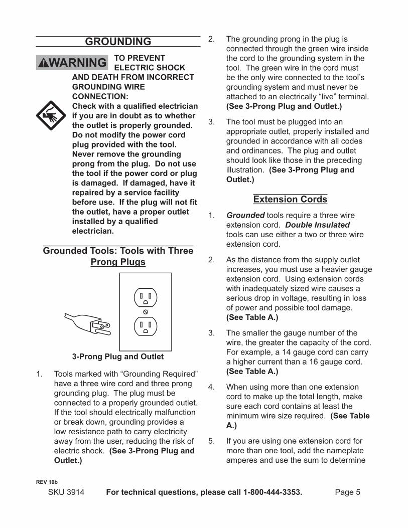
Tools marked with “Grounding Required” 1. have a three wire cord and three prong grounding plug. The plug must be connected to a properly grounded outlet. If the tool should electrically malfunction or break down, grounding provides a low resistance path to carry electricity away from the user, reducing the risk of electric shock. (See 3-prong plug and Outlet.)
The grounding prong in the plug is 2. connected through the green wire inside the cord to the grounding system in the tool. The green wire in the cord must be the only wire connected to the tool’s grounding system and must never be attached to an electrically “live” terminal. (See 3-prong plug and Outlet.)
The tool must be plugged into an 3. appropriate outlet, properly installed and grounded in accordance with all codes and ordinances. The plug and outlet should look like those in the preceding illustration. (See 3-prong plug and Outlet.)
extension cordsGrounded1. tools require a three wire extension cord. Double Insulated tools can use either a two or three wire extension cord.
As the distance from the supply outlet 2. increases, you must use a heavier gauge extension cord. Using extension cords with inadequately sized wire causes a serious drop in voltage, resulting in loss of power and possible tool damage. (See table a.)
The smaller the gauge number of the 3. wire, the greater the capacity of the cord. For example, a 14 gauge cord can carry a higher current than a 16 gauge cord. (See table a.)
When using more than one extension 4. cord to make up the total length, make sure each cord contains at least the minimum wire size required. (See table a.)
If you are using one extension cord for 5. more than one tool, add the nameplate amperes and use the sum to determine
reV 10b
Page 6 For technical questions, please call 1-800-444-3353. SKU 3914
the required minimum cord size. (See table a.)
If you are using an extension cord 6. outdoors, make sure it is marked with the suffix “W-A” (“W” in Canada) to indicate it is acceptable for outdoor use.
Make sure the extension cord is properly 7. wired and in good electrical condition. Always replace a damaged extension cord or have it repaired by a qualified electrician before using it.
Protect the extension cords from sharp 8. objects, excessive heat, and damp or wet areas.
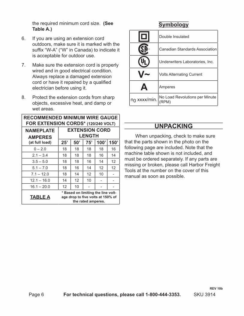
recOMMended MiniMuM wire gauge FOr eXtenSiOn cOrdS* (120/240 VOlt)
naMeplateaMpereS(at full load)
eXtenSiOn cOrd length
25’ 50’ 75’ 100’ 150’0 – 2.0 18 18 18 18 16
2.1 – 3.4 18 18 18 16 143.5 – 5.0 18 18 16 14 125.1 – 7.0 18 16 14 12 12
7.1 – 12.0 18 14 12 10 -12.1 – 16.0 14 12 10 - -16.1 – 20.0 12 10 - - -
taBle a* Based on limiting the line volt-age drop to five volts at 150% of
the rated amperes.
Symbology
Double Insulated
Canadian Standards Association
Underwriters Laboratories, Inc.
V~ Volts Alternating Current
a Amperes
n0 xxxx/min. No Load Revolutions per Minute (RPM)
unpacKingWhen unpacking, check to make sure
that the parts shown in the photo on the following page are included. Note that the machine table shown is not included, and must be ordered separately. If any parts are missing or broken, please call Harbor Freight Tools at the number on the cover of this manual as soon as possible.
reV 10b
Page 7For technical questions, please call 1-800-444-3353.SKU 3914
aSSeMBly
Sewing Machine
Motor
power Switch
Knee lifting arm for presser Foot
table Stand and top (not provided)
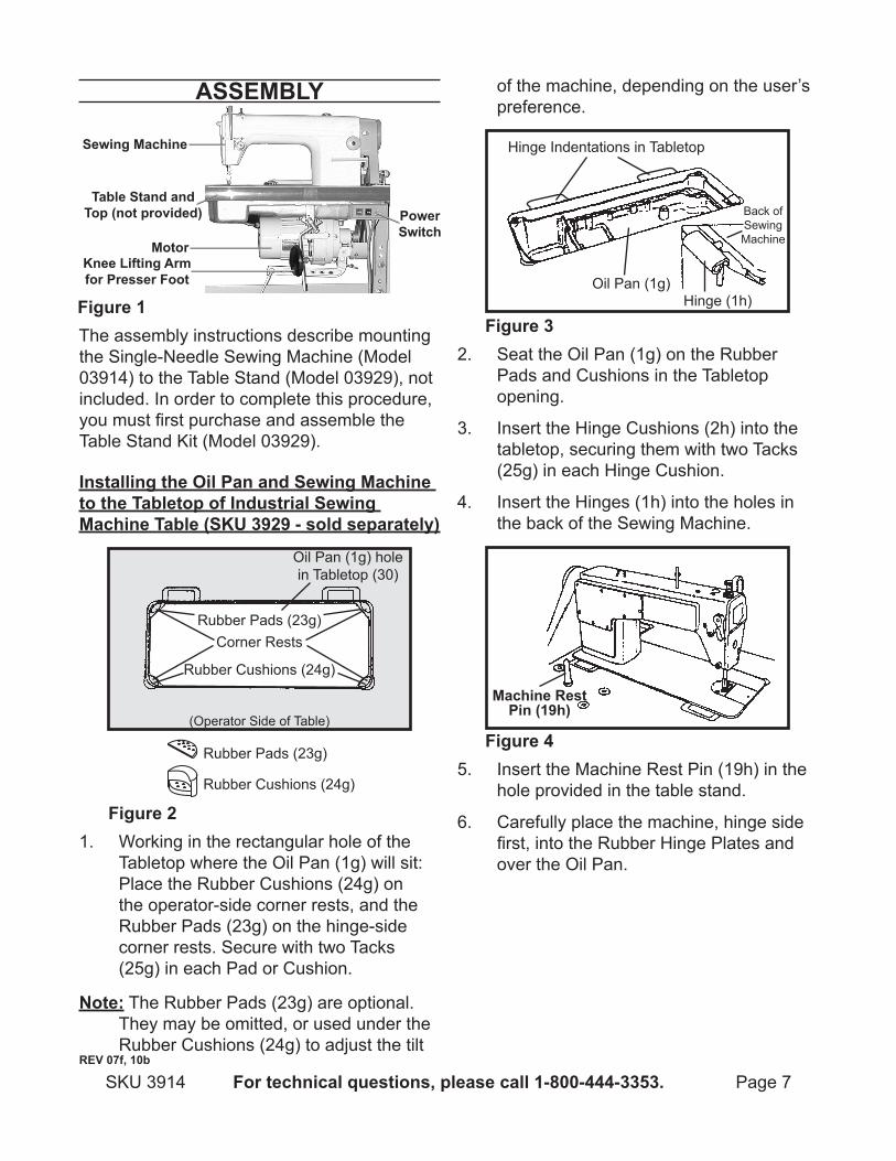
Figure 1The assembly instructions describe mounting the Single-Needle Sewing Machine (Model 03914) to the Table Stand (Model 03929), not included. In order to complete this procedure, you must first purchase and assemble the Table Stand Kit (Model 03929).
installing the Oil pan and Sewing Machine to the tabletop of industrial Sewing Machine table (SKu 3929 - sold separately)
Figure 2
Rubber Cushions (24g)
Rubber Cushions (24g)
Rubber Pads (23g)
Rubber Pads (23g)
Corner Rests
Oil Pan (1g) hole in Tabletop (30)
(Operator Side of Table)
1. Working in the rectangular hole of the Tabletop where the Oil Pan (1g) will sit: Place the Rubber Cushions (24g) on the operator-side corner rests, and the Rubber Pads (23g) on the hinge-side corner rests. Secure with two Tacks (25g) in each Pad or Cushion.
note: The Rubber Pads (23g) are optional. They may be omitted, or used under the Rubber Cushions (24g) to adjust the tilt
of the machine, depending on the user’s preference.
Figure 3
Back of Sewing Machine
Hinge (1h)
Hinge Indentations in Tabletop
Oil Pan (1g)
2. Seat the Oil Pan (1g) on the Rubber Pads and Cushions in the Tabletop opening.
Insert the Hinge Cushions (2h) into the 3. tabletop, securing them with two Tacks (25g) in each Hinge Cushion.
Insert the Hinges (1h) into the holes in 4. the back of the Sewing Machine.
Machine rest pin (19h)
Figure 45. Insert the Machine Rest Pin (19h) in the
hole provided in the table stand.
Carefully place the machine, hinge side 6. first, into the Rubber Hinge Plates and over the Oil Pan.
reV 07f, 10b
Page 8 For technical questions, please call 1-800-444-3353. SKU 3914
Knee Press Lifter Rod (2g) Oil Pan Magnet
(22g)
Oil Sight Window (1f)
Figure 5
Hand Wheel (7b)
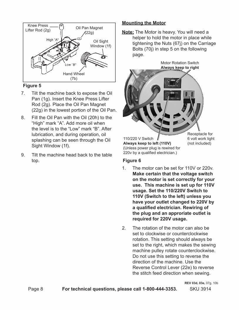
7. Tilt the machine back to expose the Oil Pan (1g). Insert the Knee Press Lifter Rod (2g). Place the Oil Pan Magnet (22g) in the lowest portion of the Oil Pan. Fill the Oil Pan with the Oil (20h) to the 8. “High” mark “A”. Add more oil when the level is to the “Low” mark “B”. After lubrication, and during operation, oil splashing can be seen through the Oil Sight Window (1f).
Tilt the machine head back to the table 9. top.
Mounting the Motor
note: The Motor is heavy. You will need a helper to hold the motor in place while tightening the Nuts (67j) on the Carriage Bolts (70j) in step 5 on the following page.
Motor Rotation Switchalways keep to right
Receptacle for 6 volt work light (not included)
110/220 V Switchalways keep to left (110V)(Unless power plug is rewired for 220v by a qualified electrician.)
Figure 61. The motor can be set for 110V or 220v.
Make certain that the voltage switch on the motor is set correctly for your use. this machine is set up for 110V usage. Set the 110/220V Switch to 110V (Switch to the left) unless you have your outlet changed to 220V by a qualified electrician. rewiring of the plug and an approriate outlet is required for 220V usage.
The rotation of the motor can also be 2. set to clockwise or counterclockwise rotation. This setting should always be set to the right, which makes the sewing machine pulley rotate counterclockwise. Do not use this setting to reverse the direction of the machine. Use the Reverse Control Lever (22e) to reverse the stitch feed direction when sewing.
reV 03d, 03e, 07g, 10b
Page 9For technical questions, please call 1-800-444-3353.SKU 3914
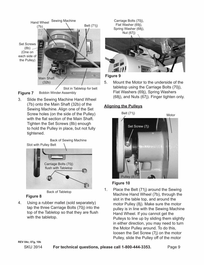
Figure 7
Hand Wheel (7b)
Sewing Machine
Set Screws (8b)
(One on each side of the Pulley)
Belt (71j)
Slot in Tabletop for belt
Main Shaft (32b)
Bobbin Winder Assembly
3. Slide the Sewing Machine Hand Wheel (7b) onto the Main Shaft (32b) of the Sewing Machine. Align one of the Set Screw holes (on the side of the Pulley) with the flat section of the Main Shaft. Tighten the Set Screws (8b) enough to hold the Pulley in place, but not fully tightened.
Figure 8
Carriage Bolts (70j) flush with Tabletop
Back of Tabletop
Back of Sewing MachineSlot with Pulley Belt
4. Using a rubber mallet (sold separately) tap the three Carriage Bolts (70j) into the top of the Tabletop so that they are flush with the tabletop.
Carriage Bolts (70j),Flat Washer (69j),
Spring Washer (68j),Nut (67j)
Figure 95. Mount the Motor to the underside of the
tabletop using the Carriage Bolts (70j), Flat Washers (69j), Spring Washers (68j), and Nuts (67j). Finger tighten only.
aligning the pulleys
Figure 10
Set Screw (7j)
Pulley (8j)
MotorBelt (71j)
1. Place the Belt (71j) around the Sewing Machine Hand Wheel (7b), through the slot in the table top, and around the motor Pulley (8j). Make sure the motor pulley is in line with the Sewing Machine Hand Wheel. If you cannot get the Pulleys to line up by sliding them slightly in either direction, you may need to turn the Motor Pulley around. To do this, loosen the Set Screw (7j) on the motor Pulley, slide the Pulley off of the motor
reV 04c; 07g, 10b
Page 10 For technical questions, please call 1-800-444-3353. SKU 3914
reV 04c, 05d, 07g, 10b
and turn it around. Move the belt by hand to verify that it is aligned and tracking correctly.
Once you have the Pulleys aligned, 2. remove the Belt from the Sewing Machine Hand Wheel (7b), and tighten its Set Screws (8b). Replace the Pulley and tighten the Motor Set Screw (7j).
Attach the Pulley Safety Cover (1j) over 3. the motor Pulley (8j), using the Bolt (2j), Spring Washer (3j), Flat Washer (4j), and Lock Nut (5j).
adjusting the Belt tension
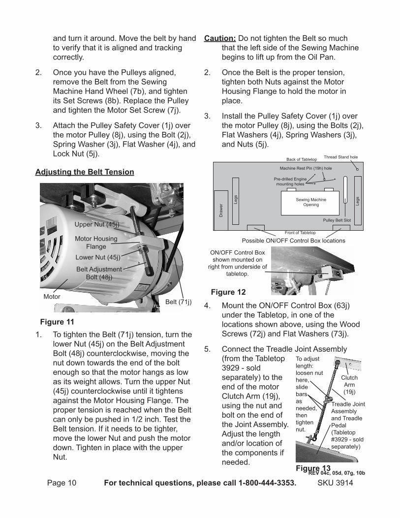
Figure 11
Belt Adjustment Bolt (48j)
Lower Nut (45j)
Belt (71j)Motor
Upper Nut (45j)
Motor Housing Flange
1. To tighten the Belt (71j) tension, turn the lower Nut (45j) on the Belt Adjustment Bolt (48j) counterclockwise, moving the nut down towards the end of the bolt enough so that the motor hangs as low as its weight allows. Turn the upper Nut (45j) counterclockwise until it tightens against the Motor Housing Flange. The proper tension is reached when the Belt can only be pushed in 1/2 inch. Test the Belt tension. If it needs to be tighter, move the lower Nut and push the motor down. Tighten in place with the upper Nut.
caution: Do not tighten the Belt so much that the left side of the Sewing Machine begins to lift up from the Oil Pan.
Once the Belt is the proper tension, 2. tighten both Nuts against the Motor Housing Flange to hold the motor in place.
Install the Pulley Safety Cover (1j) over 3. the motor Pulley (8j), using the Bolts (2j), Flat Washers (4j), Spring Washers (3j), and Nuts (5j).
Legs
Legs
Dra
wer
Possible ON/OFF Control Box locations
Pre-drilled Engine mounting holes
Machine Rest Pin (19h) hole
Thread Stand hole
Pulley Belt Slot
Sewing MachineOpening
Back of Tabletop
Front of Tabletop
Figure 12
ON/OFF Control Box shown mounted on
right from underside of tabletop.
4. Mount the ON/OFF Control Box (63j) under the Tabletop, in one of the locations shown above, using the Wood Screws (72j) and Flat Washers (73j).
5. Connect the Treadle Joint Assembly (from the Tabletop 3929 - sold separately) to the end of the motor Clutch Arm (19j), using the nut and bolt on the end of the Joint Assembly. Adjust the length and/or location of the components if needed.
Clutch Arm (19j)
Figure 13
Treadle Joint Assembly and Treadle Pedal (Tabletop #3929 - sold separately)
To adjust length: loosen nut here,slide bars asneeded,thentightennut.
Page 11For technical questions, please call 1-800-444-3353.SKU 3914
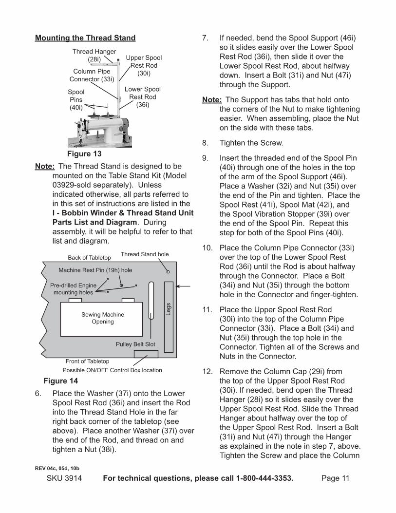
Mounting the thread Stand
Figure 13
Thread Hanger (28i) Upper Spool
Rest Rod (30i)
Lower Spool Rest Rod
(36i)
Column Pipe Connector (33i)
Spool Pins (40i)
note: The Thread Stand is designed to be mounted on the Table Stand Kit (Model 03929-sold separately). Unless indicated otherwise, all parts referred to in this set of instructions are listed in the i - Bobbin winder & thread Stand unit parts list and diagram. During assembly, it will be helpful to refer to that list and diagram.
Legs
Possible ON/OFF Control Box location
Pre-drilled Engine mounting holes
Machine Rest Pin (19h) hole
Thread Stand hole
Pulley Belt Slot
Sewing MachineOpening
Back of Tabletop
Front of Tabletop
Figure 146. Place the Washer (37i) onto the Lower
Spool Rest Rod (36i) and insert the Rod into the Thread Stand Hole in the far right back corner of the tabletop (see above). Place another Washer (37i) over the end of the Rod, and thread on and tighten a Nut (38i).
If needed, bend the Spool Support (46i) 7. so it slides easily over the Lower Spool Rest Rod (36i), then slide it over the Lower Spool Rest Rod, about halfway down. Insert a Bolt (31i) and Nut (47i) through the Support.
note: The Support has tabs that hold onto the corners of the Nut to make tightening easier. When assembling, place the Nut on the side with these tabs.
Tighten the Screw.8.
Insert the threaded end of the Spool Pin 9. (40i) through one of the holes in the top of the arm of the Spool Support (46i). Place a Washer (32i) and Nut (35i) over the end of the Pin and tighten. Place the Spool Rest (41i), Spool Mat (42i), and the Spool Vibration Stopper (39i) over the end of the Spool Pin. Repeat this step for both of the Spool Pins (40i).
Place the Column Pipe Connector (33i) 10. over the top of the Lower Spool Rest Rod (36i) until the Rod is about halfway through the Connector. Place a Bolt (34i) and Nut (35i) through the bottom hole in the Connector and finger-tighten.
Place the Upper Spool Rest Rod 11. (30i) into the top of the Column Pipe Connector (33i). Place a Bolt (34i) and Nut (35i) through the top hole in the Connector. Tighten all of the Screws and Nuts in the Connector.
Remove the Column Cap (29i) from 12. the top of the Upper Spool Rest Rod (30i). If needed, bend open the Thread Hanger (28i) so it slides easily over the Upper Spool Rest Rod. Slide the Thread Hanger about halfway over the top of the Upper Spool Rest Rod. Insert a Bolt (31i) and Nut (47i) through the Hanger as explained in the note in step 7, above. Tighten the Screw and place the Column
reV 04c, 05d, 10b
Page 12 For technical questions, please call 1-800-444-3353. SKU 3914
Cap over the end of the Upper Spool Rest Rod.
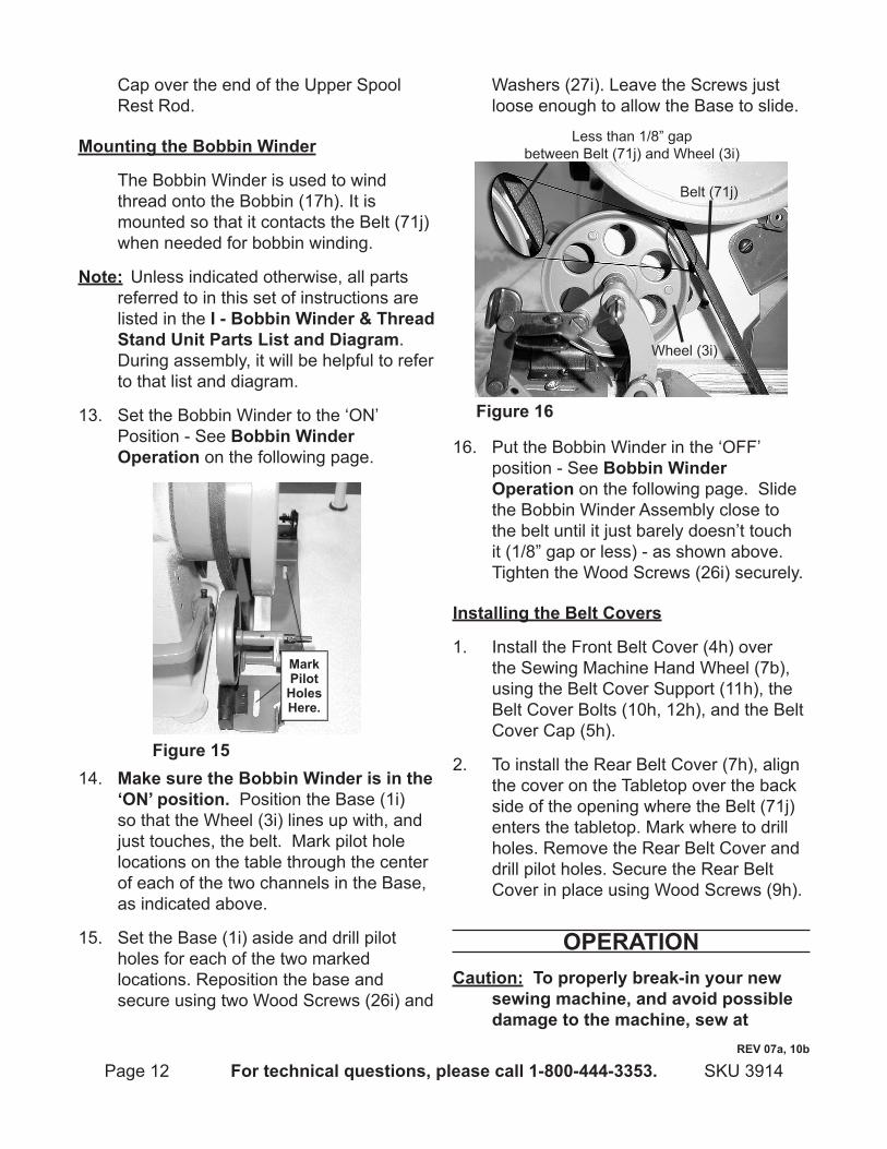
Mounting the Bobbin winder
The Bobbin Winder is used to wind thread onto the Bobbin (17h). It is mounted so that it contacts the Belt (71j) when needed for bobbin winding.
note: Unless indicated otherwise, all parts referred to in this set of instructions are listed in the i - Bobbin winder & thread Stand unit parts list and diagram. During assembly, it will be helpful to refer to that list and diagram.
Set the Bobbin Winder to the ‘ON’ 13. Position - See Bobbin winder Operation on the following page.
Figure 15
Mark pilot holes here.
14. Make sure the Bobbin winder is in the ‘On’ position. Position the Base (1i) so that the Wheel (3i) lines up with, and just touches, the belt. Mark pilot hole locations on the table through the center of each of the two channels in the Base, as indicated above.
Set the Base (1i) aside and drill pilot 15. holes for each of the two marked locations. Reposition the base and secure using two Wood Screws (26i) and
Washers (27i). Leave the Screws just loose enough to allow the Base to slide.
Figure 16
Belt (71j)
Wheel (3i)
Less than 1/8” gap between Belt (71j) and Wheel (3i)
16. Put the Bobbin Winder in the ‘OFF’ position - See Bobbin winder Operation on the following page. Slide the Bobbin Winder Assembly close to the belt until it just barely doesn’t touch it (1/8” gap or less) - as shown above. Tighten the Wood Screws (26i) securely.
installing the Belt covers
Install the Front Belt Cover (4h) over 1. the Sewing Machine Hand Wheel (7b), using the Belt Cover Support (11h), the Belt Cover Bolts (10h, 12h), and the Belt Cover Cap (5h).
To install the Rear Belt Cover (7h), align 2. the cover on the Tabletop over the back side of the opening where the Belt (71j) enters the tabletop. Mark where to drill holes. Remove the Rear Belt Cover and drill pilot holes. Secure the Rear Belt Cover in place using Wood Screws (9h).
OperatiOncaution: to properly break-in your new
sewing machine, and avoid possible damage to the machine, sew at
reV 07a, 10b

Page 13For technical questions, please call 1-800-444-3353.SKU 3914
moderate to slow speeds for the first 15 minutes of use.
warning: Shut the machine off completely before working around the needle or other moving parts.
BaSic SettingS
You will need to make the following adjustments on a regular basis when using the machine.
attaching the needleThe needles supplied with the Sewing Machine are size 90/14 (DBX1). The shank is size 16 x 257. For leatherwork use a 16 x 95 needle. This machine can accommodate a needle up to size 22.
note: Industrial sewing machine needles have a round shank (the top part of the needle that slides up into the machine). Do not use needles, such as most home sewing needles, which have a flat area on the shank of the needle.
Unplug the Power Cord.1.
Select the proper needle size for the 2. thread count and material being sewn.
Turn the Hand Wheel (7b) 3. counterclockwise until the Needle Bar reaches the highest point of its stroke.
Side ViewFront ViewFigure 17
Face indented section to right when inserting needle
Loosen Bolt (25c)
Shank
4. Loosen the Bolt (25c) and hold Needle (23c) with its indented part facing to the
right. Insert the Needle and push it up until it will go no farther.
While holding in place, securely tighten 5. the Bolt.
Bobbin winder OperationThe Bobbin Winder is used to wind thread onto the Bobbin. The Bobbin Winder has two positions, ‘ON’ and ‘OFF’:
OFF position
Figure 18OFF
position
Pull tab on Connecting Rod (6i)to disengage Winder
Pull the tab on the Connecting Rod (6i) to disengage the Winder from the Belt. The Bobbin Winder will not contact the belt.
On position
Figure 19On
position
Press here to push Winder toward Belt
This position is with the Connecting Rod (6i) pressed, as shown above. The Shaft on the Bobbin Winder will spin, winding thread onto the Bobbin.
reV 07a, 10b
Page 14 For technical questions, please call 1-800-444-3353. SKU 3914
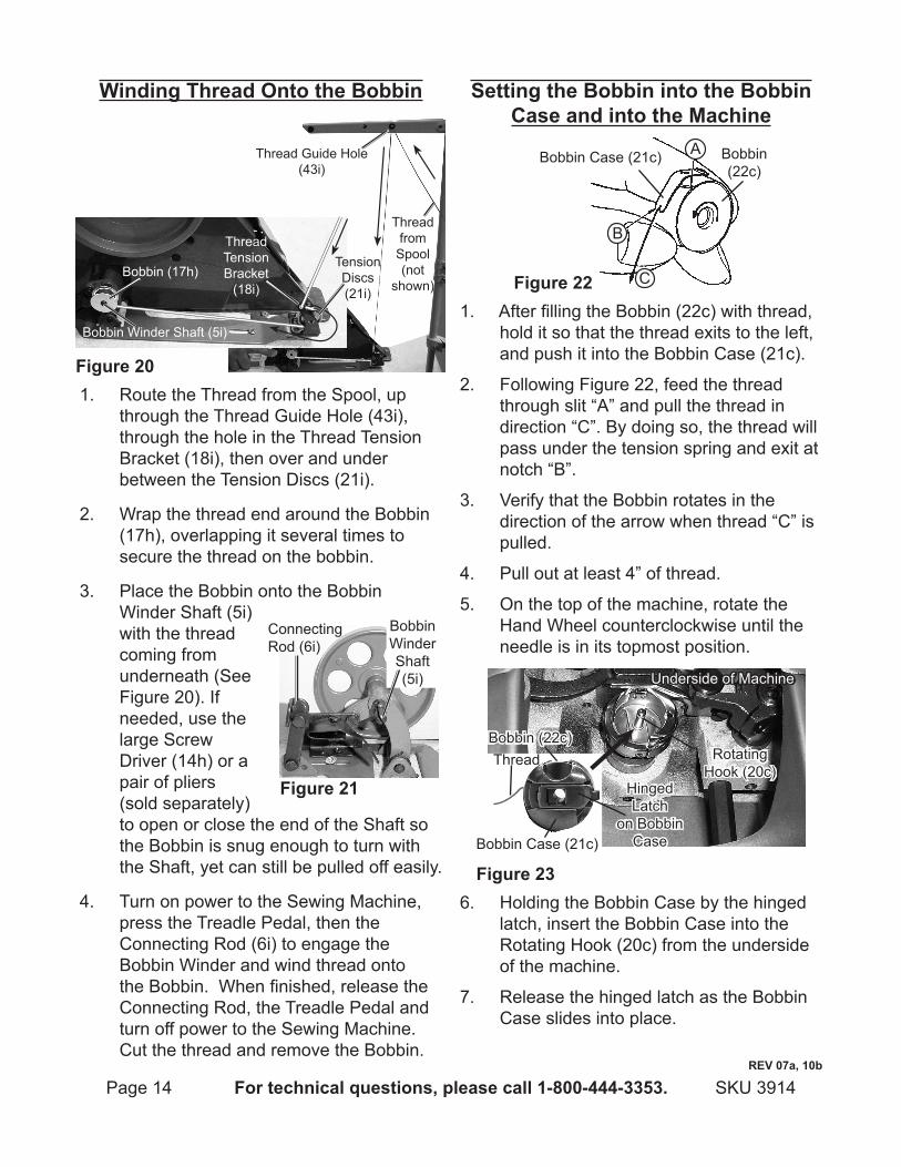
winding thread Onto the Bobbin
Thread Guide Hole (43i)
Thread from
Spool (not
shown)
Figure 20
Bobbin Winder Shaft (5i)
Thread Tension Bracket
(18i)
Tension Discs (21i)
Bobbin (17h)
1. Route the Thread from the Spool, up through the Thread Guide Hole (43i), through the hole in the Thread Tension Bracket (18i), then over and under between the Tension Discs (21i).
Wrap the thread end around the Bobbin 2. (17h), overlapping it several times to secure the thread on the bobbin.
3. Place the Bobbin onto the Bobbin Winder Shaft (5i) with the thread coming from underneath (See Figure 20). If needed, use the large Screw Driver (14h) or a pair of pliers (sold separately) to open or close the end of the Shaft so the Bobbin is snug enough to turn with the Shaft, yet can still be pulled off easily.
Turn on power to the Sewing Machine, 4. press the Treadle Pedal, then the Connecting Rod (6i) to engage the Bobbin Winder and wind thread onto the Bobbin. When finished, release the Connecting Rod, the Treadle Pedal and turn off power to the Sewing Machine. Cut the thread and remove the Bobbin.
Setting the Bobbin into the Bobbin case and into the Machine
Figure 22
A
B
C
Bobbin (22c)
Bobbin Case (21c)
1. After filling the Bobbin (22c) with thread, hold it so that the thread exits to the left, and push it into the Bobbin Case (21c).
Following Figure 22, feed the thread 2. through slit “A” and pull the thread in direction “C”. By doing so, the thread will pass under the tension spring and exit at notch “B”.
Verify that the Bobbin rotates in the 3. direction of the arrow when thread “C” is pulled.
Pull out at least 4” of thread.4.
On the top of the machine, rotate the 5. Hand Wheel counterclockwise until the needle is in its topmost position.
Figure 23
Bobbin Case (21c)
Hinged Latch
on Bobbin Case
Bobbin (22c)Thread
Underside of Machine
Rotating Hook (20c)
6. Holding the Bobbin Case by the hinged latch, insert the Bobbin Case into the Rotating Hook (20c) from the underside of the machine.
Release the hinged latch as the Bobbin 7. Case slides into place.
Figure 21
Bobbin Winder Shaft (5i)
Connecting Rod (6i)
reV 07a, 10b
Page 15For technical questions, please call 1-800-444-3353.SKU 3914
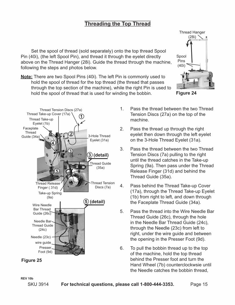
Figure 25
3 (detail)
Thread Tension Discs (27a)
Thread Take-up Eyelet (1b)
Thread Take-up Cover (17a)
Faceplate Thread
Guide (34a)
Thread Tension Discs (7a)
3-Hole Thread Eyelet (31a)
Thread Release Finger ( 31d)
Thread Guide (35a)
Take-up Spring (9a)
5 (detail)
Needle Bar Thread Guide
(24c)
Presser Foot (9d)
wire guideNeedle (23c)
Wire Needle Bar Thread Guide (26c)
1
2
4
3
5
Pass the thread between the two Thread 1. Tension Discs (27a) on the top of the machine.
Pass the thread up through the right 2. eyelet then down through the left eyelet on the 3-Hole Thread Eyelet (31a).
Pass the thread between the two Thread 3. Tension Discs (7a) pulling to the right until the thread catches in the Take-up Spring (9a). Then pass under the Thread Release Finger (31d) and behind the Thread Guide (35a).
Pass behind the Thread Take-up Cover 4. (17a), through the Thread Take-up Eyelet (1b) from right to left, and down through the Faceplate Thread Guide (34a).
Pass the thread into the Wire Needle Bar 5. Thread Guide (26c), through the hole in the Needle Bar Thread Guide (24c), through the Needle (23c) from left to right, under the wire guide and between the opening in the Presser Foot (9d).
To pull the bobbin thread up to the top 6. of the machine, hold the top thread behind the Presser foot and turn the Hand Wheel (7b) counterclockwsie until the Needle catches the bobbin thread,
reV 10b
threading the top thread
Set the spool of thread (sold separately) onto the top thread Spool Pin (40i), (the left Spool Pin), and thread it through the eyelet directly above on the Thread Hanger (28i). Guide the thread through the machine, following the steps and photos below.
note: There are two Spool Pins (40i). The left Pin is commonly used to hold the spool of thread for the top thread (the thread that passes through the top section of the machine), while the right Pin is used to hold the spool of thread that is used for winding the bobbin. Figure 24
Thread Hanger (28i)
Spool Pins (40i)
Page 16 For technical questions, please call 1-800-444-3353. SKU 3914
pulling it to the top of the machine. Pull both threads behind the Presser Foot, leaving at least 4” of excess thread.
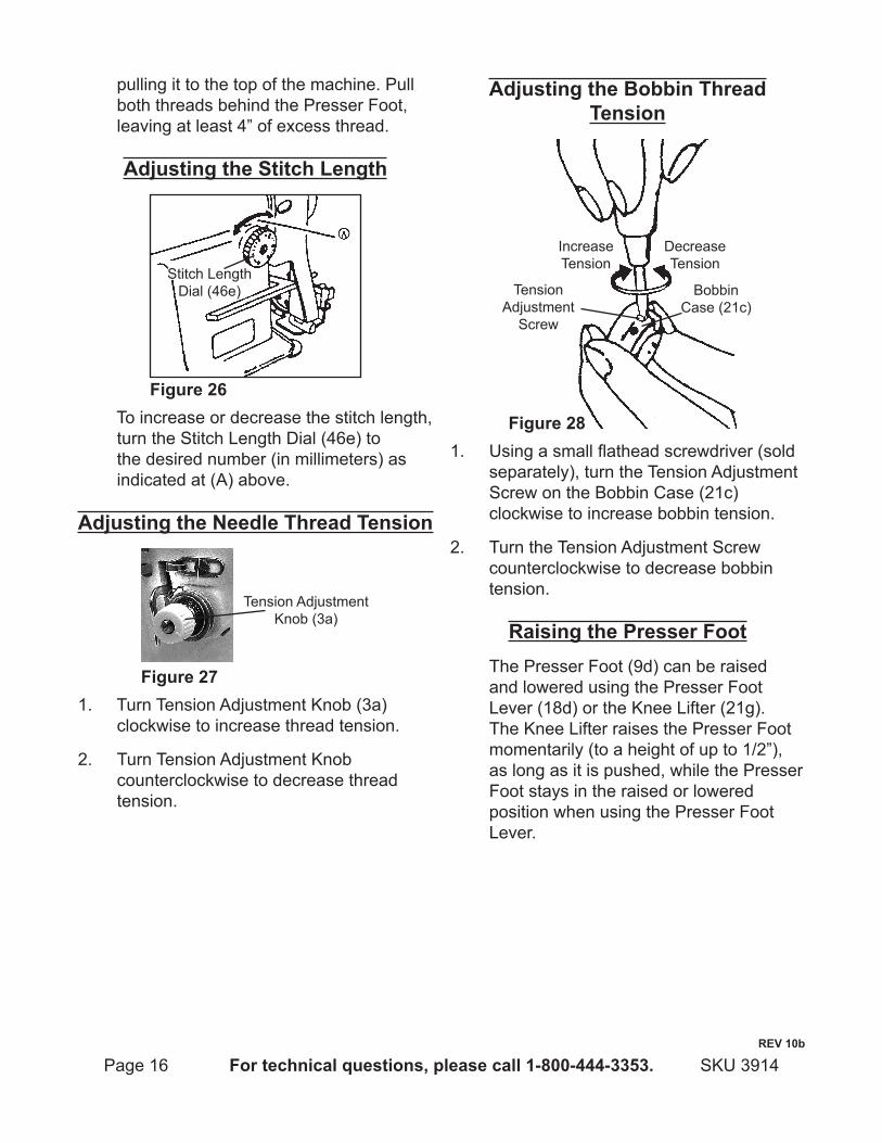
adjusting the Stitch length
Figure 26
Stitch Length Dial (46e)
To increase or decrease the stitch length, turn the Stitch Length Dial (46e) to the desired number (in millimeters) as indicated at (A) above.
adjusting the needle thread tension
Figure 27
Tension Adjustment Knob (3a)
1. Turn Tension Adjustment Knob (3a) clockwise to increase thread tension.
Turn Tension Adjustment Knob 2. counterclockwise to decrease thread tension.
adjusting the Bobbin thread tension
Figure 28
Increase Tension
Decrease Tension
Bobbin Case (21c)
Tension Adjustment
Screw
1. Using a small flathead screwdriver (sold separately), turn the Tension Adjustment Screw on the Bobbin Case (21c)clockwise to increase bobbin tension.
Turn the Tension Adjustment Screw 2. counterclockwise to decrease bobbin tension.
raising the presser Foot The Presser Foot (9d) can be raised and lowered using the Presser Foot Lever (18d) or the Knee Lifter (21g). The Knee Lifter raises the Presser Foot momentarily (to a height of up to 1/2”), as long as it is pushed, while the Presser Foot stays in the raised or lowered position when using the Presser Foot Lever.
reV 10b

Page 17For technical questions, please call 1-800-444-3353.SKU 3914
Figure 29
Presser Foot Lever
(18d)
Raises Presser
Foot
Lowers Presser
Foot
1. To raise the Presser Foot, turn the Presser Foot Lever up. The Presser Foot will go up about 1/4” and stop.
To lower the Presser Foot, turn the 2. Presser Foot Lever down.
Setting the presser Foot pressure
Figure 30
Increase Tension
Decrease Tension Presser
Regulator (20d)
Presser Spring
Regulator Nut (19d)
1. Loosen the Presser Spring Regulator Nut (19d) by turning it counterclockwise.
Turn the Presser Regulator (20d) 2. clockwise to increase Presser Foot pressure and counterclockwise to decrease Presser Foot pressure.
After adjustment, tighten the Presser 3. Spring Regulator Nut.
adVanced SettingS
The Sewing Machine is set at the factory for using with jean weight materials. The following adjustments are needed only when using the machine for unusual types of fabric or when changing machine components. These procedures should be performed only by a qualified sewing machine technician.
adjusting the Feed timing
Set Screws
Rotating Hook (20c)
Figure 311. Loosen Set Screws on the side of the
Rotating Hook (20c) and re-position the Rotating Hook as follows:To advance the feed timing in order to a. prevent uneven material feed, rotate the Rotating Hook up (clockwise).To delay the feed timing in order to b. increase stitch tightness, rotate the Rotating Hook down (counterclockwise).
Retighten the Set Screws.2.
adjusting Feed dog heightThe Feed Dog is factory adjusted so that
it juts out from the Throat Plate surface .031” (0.8 mm) to .035” (0.9 mm). If the Feed Dog juts out too much, puckering may result when sewing lightweight materials. To adjust the height of the Feed Dog:
reV 10b
Page 18 For technical questions, please call 1-800-444-3353. SKU 3914
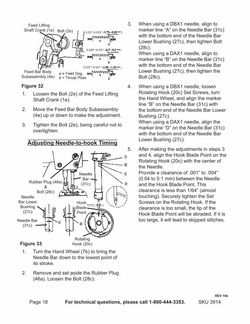
Feed Lifting Shaft Crank (1e)
Feed Bar Body Subassembly (4e)
Bolt (2e)
Figure 32
0.03”~0.033” ( )
0.028”~0.031” ( )
0.037”~0.041” ( )
1. Loosen the Bolt (2e) of the Feed Lifting Shaft Crank (1e).
Move the Feed Bar Body Subassembly 2. (4e) up or down to make the adjustment.
Tighten the Bolt (2e), being careful not to 3. overtighten.
adjusting needle-to-hook timing
Figure 33
Rubber Plug (46a)&
Bolt (28c)
Needle Bar (31c)
Needle Bar
(31c)
Needle Bar Lower Bushing
(27c)
Hook Blade Point
Rotating Hook (20c)
1. Turn the Hand Wheel (7b) to bring the Needle Bar down to the lowest point of its stroke.
Remove and set aside the Rubber Plug 2. (46a). Loosen the Bolt (28c).
When using a DBX1 needle, align to 3. marker line “A” on the Needle Bar (31c) with the bottom end of the Needle Bar Lower Bushing (27c), then tighten Bolt (28c). When using a DAX1 needle, align to marker line “B” on the Needle Bar (31c) with the bottom end of the Needle Bar Lower Bushing (27c), then tighten the Bolt (28c).
When using a DBX1 needle, loosen 4. Rotating Hook (20c) Set Screws, turn the Hand Wheel, and align the marker line “B” on the Needle Bar (31c) with the bottom end of the Needle Bar Lower Bushing (27c). When using a DAX1 needle, align the marker line “D” on the Needle Bar (31c) with the bottom end of the Needle Bar Lower Bushing (27c).
After making the adjustments in steps 3 5. and 4, align the Hook Blade Point on the Rotating Hook (20c) with the center of the Needle. Provide a clearance of .001” to .004” (0.04 to 0.1 mm) between the Needle and the Hook Blade Point. This clearance is less than 1/64” (almost touching). Securely tighten the Set Screws on the Rotating Hook. If the clearance is too small, the tip of the Hook Blade Point will be abraded. If it is too large, it will lead to skipped stitches.
reV 10b
Page 19For technical questions, please call 1-800-444-3353.SKU 3914
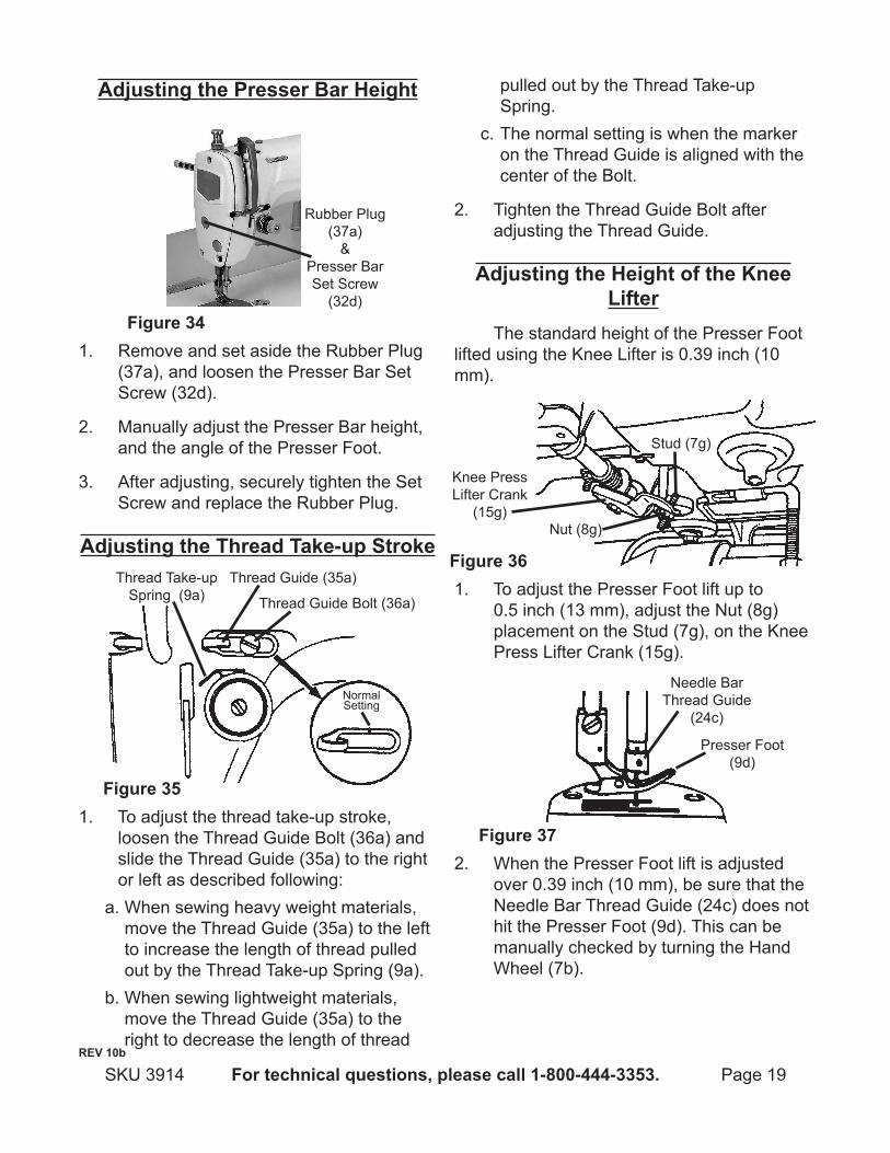
adjusting the presser Bar height
Figure 34
Rubber Plug (37a)
& Presser Bar Set Screw
(32d)
1. Remove and set aside the Rubber Plug (37a), and loosen the Presser Bar Set Screw (32d).
Manually adjust the Presser Bar height, 2. and the angle of the Presser Foot.
After adjusting, securely tighten the Set 3. Screw and replace the Rubber Plug.
adjusting the thread take-up Stroke
Figure 35
Thread Guide (35a)
Thread Guide Bolt (36a)
Normal Setting
Thread Take-up Spring (9a)
1. To adjust the thread take-up stroke, loosen the Thread Guide Bolt (36a) and slide the Thread Guide (35a) to the right or left as described following:When sewing heavy weight materials, a. move the Thread Guide (35a) to the left to increase the length of thread pulled out by the Thread Take-up Spring (9a).When sewing lightweight materials, b. move the Thread Guide (35a) to the right to decrease the length of thread
pulled out by the Thread Take-up Spring.The normal setting is when the marker c. on the Thread Guide is aligned with the center of the Bolt.
Tighten the Thread Guide Bolt after 2. adjusting the Thread Guide.
adjusting the height of the Knee lifter
The standard height of the Presser Foot lifted using the Knee Lifter is 0.39 inch (10 mm).
Figure 36
Nut (8g)
Stud (7g)
Knee Press Lifter Crank
(15g)
1. To adjust the Presser Foot lift up to 0.5 inch (13 mm), adjust the Nut (8g) placement on the Stud (7g), on the Knee Press Lifter Crank (15g).
Figure 37
Needle Bar Thread Guide
(24c)
Presser Foot (9d)
2. When the Presser Foot lift is adjusted over 0.39 inch (10 mm), be sure that the Needle Bar Thread Guide (24c) does not hit the Presser Foot (9d). This can be manually checked by turning the Hand Wheel (7b).
reV 10b
Page 20 For technical questions, please call 1-800-444-3353. SKU 3914
adjusting Sewing Speed with pulleys (sold separately)
This machine is a fast running machine. It can be adjusted to a slower running machine by changing the pulley on the motor to a smaller diameter pulley. Consult a qualified sewing machine repair shop to replace the pulley with a 1-3/4” or 1-1/2” pulley to slow the speed of the machine.
MaintenanceAdvanced Machine adjustments should 1. only be performed by a qualified technician.
Check the oil level weekly when the 2. machine is used daily. Add sewing machine oil as required to the high level marking.
Clean the machine with a clean, damp 3. cloth. Do not use solvents or thinners.
After each use, check for lint build up 4. and blow clean with pressurized air. Remove and discard any stray thread or fabric pieces.
Check the Belt (71j) tension after first 5. use and then weekly, and adjust as described in adjusting the Belt tension under the assembly instructions.
When not in use, cover the machine and 6. store in a clean and dry location.
reV 10b
Page 21For technical questions, please call 1-800-444-3353.SKU 3914
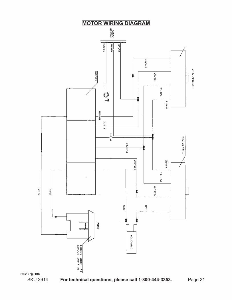
MOtOr wiring diagraM
reV 07g, 10b
Page 22 For technical questions, please call 1-800-444-3353. SKU 3914
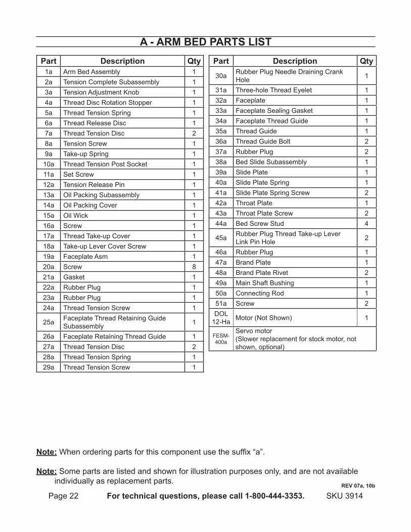
a - arM Bed partS liStpart description Qty
1a Arm Bed Assembly 12a Tension Complete Subassembly 13a Tension Adjustment Knob 14a Thread Disc Rotation Stopper 15a Thread Tension Spring 16a Thread Release Disc 17a Thread Tension Disc 28a Tension Screw 19a Take-up Spring 1
10a Thread Tension Post Socket 111a Set Screw 112a Tension Release Pin 113a Oil Packing Subassembly 114a Oil Packing Cover 115a Oil Wick 116a Screw 117a Thread Take-up Cover 118a Take-up Lever Cover Screw 119a Faceplate Asm 120a Screw 821a Gasket 122a Rubber Plug 123a Rubber Plug 124a Thread Tension Screw 1
25a Faceplate Thread Retaining Guide Subassembly 1
26a Faceplate Retaining Thread Guide 127a Thread Tension Disc 228a Thread Tension Spring 129a Thread Tension Screw 1
part description Qty
30a Rubber Plug Needle Draining Crank Hole 1
31a Three-hole Thread Eyelet 132a Faceplate 133a Faceplate Sealing Gasket 134a Faceplate Thread Guide 135a Thread Guide 136a Thread Guide Bolt 237a Rubber Plug 238a Bed Slide Subassembly 139a Slide Plate 140a Slide Plate Spring 141a Slide Plate Spring Screw 242a Throat Plate 143a Throat Plate Screw 244a Bed Screw Stud 4
45a Rubber Plug Thread Take-up Lever Link Pin Hole 2
46a Rubber Plug 147a Brand Plate 148a Brand Plate Rivet 249a Main Shaft Bushing 150a Connecting Rod 151a Screw 2DOL
12-Ha Motor (Not Shown) 1
FESM-400a
Servo motor(Slower replacement for stock motor, not shown, optional)
reV 07a, 10b
note: When ordering parts for this component use the suffix “a”.
note: Some parts are listed and shown for illustration purposes only, and are not available individually as replacement parts.

Page 23For technical questions, please call 1-800-444-3353.SKU 3914
a- arM Bed aSSeMBly drawing
46
Motor (DOL 12-Ha) (Not Shown)
Page 24 For technical questions, please call 1-800-444-3353. SKU 3914
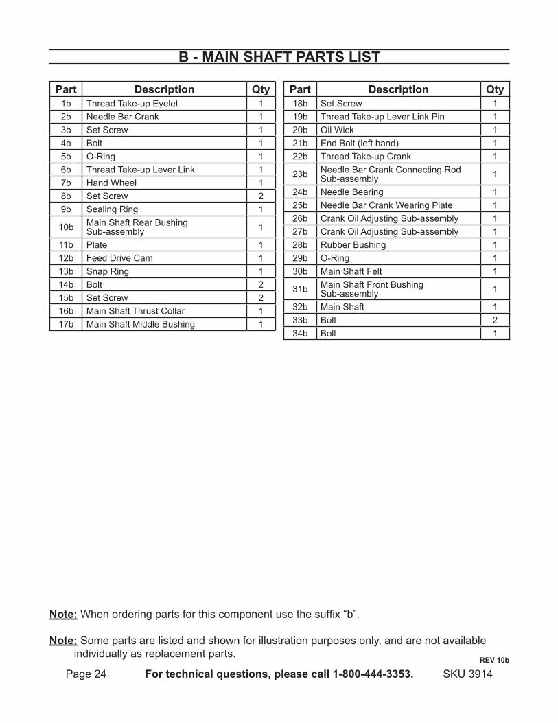
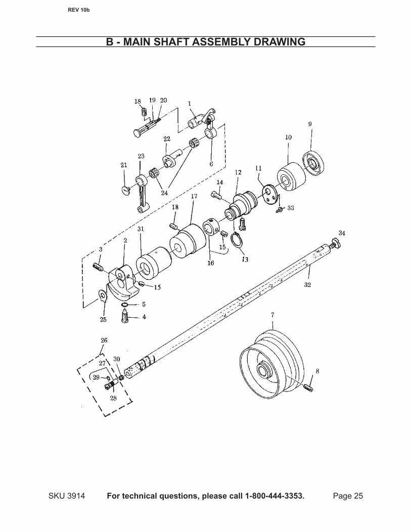
B - Main ShaFt partS liSt
part description Qty1b Thread Take-up Eyelet 12b Needle Bar Crank 13b Set Screw 14b Bolt 15b O-Ring 16b Thread Take-up Lever Link 17b Hand Wheel 18b Set Screw 29b Sealing Ring 1
10b Main Shaft Rear Bushing Sub-assembly 1
11b Plate 112b Feed Drive Cam 113b Snap Ring 114b Bolt 215b Set Screw 216b Main Shaft Thrust Collar 117b Main Shaft Middle Bushing 1
part description Qty18b Set Screw 119b Thread Take-up Lever Link Pin 120b Oil Wick 121b End Bolt (left hand) 122b Thread Take-up Crank 1
23b Needle Bar Crank Connecting Rod Sub-assembly 1
24b Needle Bearing 125b Needle Bar Crank Wearing Plate 126b Crank Oil Adjusting Sub-assembly 127b Crank Oil Adjusting Sub-assembly 128b Rubber Bushing 129b O-Ring 130b Main Shaft Felt 1
31b Main Shaft Front Bushing Sub-assembly 1
32b Main Shaft 133b Bolt 234b Bolt 1
note: When ordering parts for this component use the suffix “b”.
note: Some parts are listed and shown for illustration purposes only, and are not available individually as replacement parts.
reV 10b
Page 25For technical questions, please call 1-800-444-3353.SKU 3914
B - Main ShaFt aSSeMBly drawing
reV 10b
Page 26 For technical questions, please call 1-800-444-3353. SKU 3914
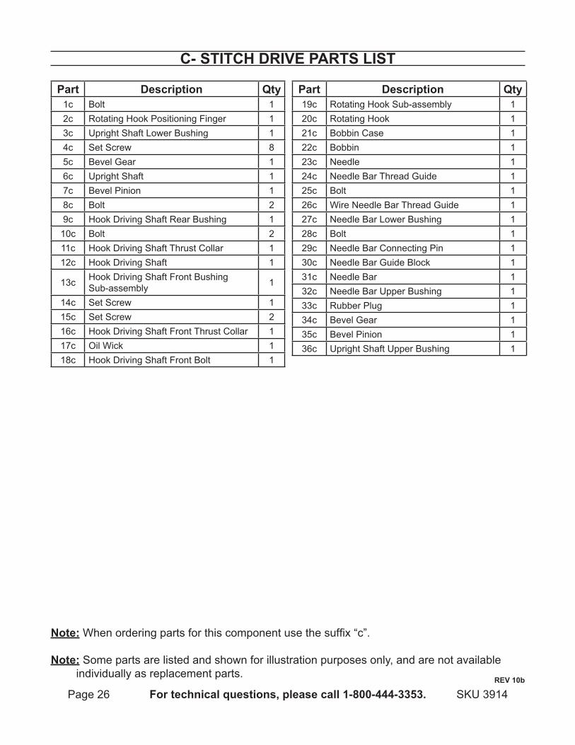
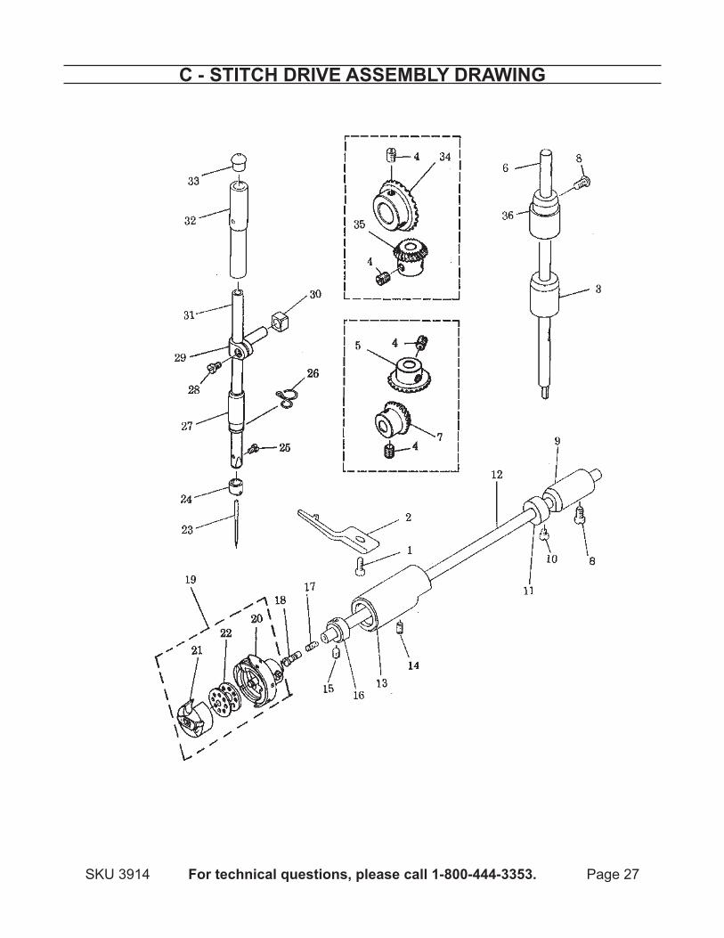
c- Stitch driVe partS liSt
part description Qty1c Bolt 12c Rotating Hook Positioning Finger 13c Upright Shaft Lower Bushing 14c Set Screw 85c Bevel Gear 16c Upright Shaft 17c Bevel Pinion 18c Bolt 29c Hook Driving Shaft Rear Bushing 1
10c Bolt 211c Hook Driving Shaft Thrust Collar 112c Hook Driving Shaft 1
13c Hook Driving Shaft Front Bushing Sub-assembly 1
14c Set Screw 115c Set Screw 216c Hook Driving Shaft Front Thrust Collar 117c Oil Wick 118c Hook Driving Shaft Front Bolt 1
part description Qty19c Rotating Hook Sub-assembly 120c Rotating Hook 121c Bobbin Case 122c Bobbin 123c Needle 124c Needle Bar Thread Guide 125c Bolt 126c Wire Needle Bar Thread Guide 127c Needle Bar Lower Bushing 128c Bolt 129c Needle Bar Connecting Pin 130c Needle Bar Guide Block 131c Needle Bar 132c Needle Bar Upper Bushing 133c Rubber Plug 134c Bevel Gear 135c Bevel Pinion 136c Upright Shaft Upper Bushing 1
note: When ordering parts for this component use the suffix “c”.
note: Some parts are listed and shown for illustration purposes only, and are not available individually as replacement parts.
reV 10b
Page 27For technical questions, please call 1-800-444-3353.SKU 3914
c - Stitch driVe aSSeMBly drawing
Page 28 For technical questions, please call 1-800-444-3353. SKU 3914
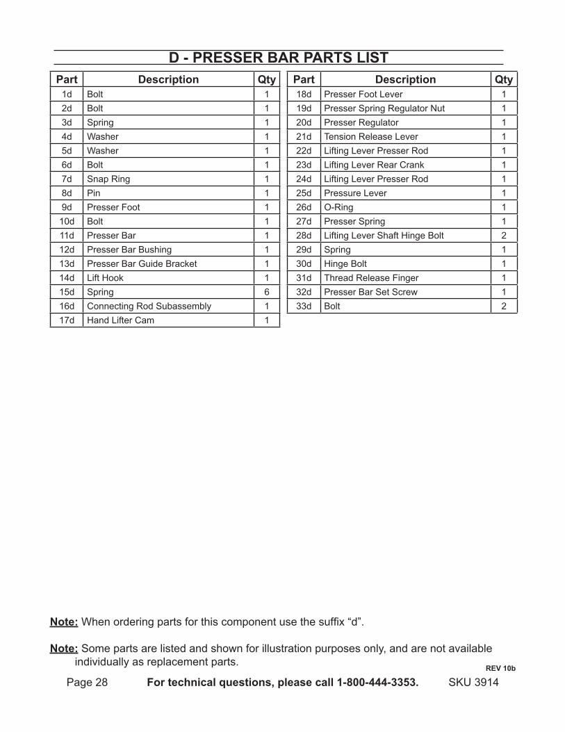
d - preSSer Bar partS liStpart description Qty
1d Bolt 12d Bolt 13d Spring 14d Washer 15d Washer 16d Bolt 17d Snap Ring 18d Pin 19d Presser Foot 1
10d Bolt 111d Presser Bar 112d Presser Bar Bushing 113d Presser Bar Guide Bracket 114d Lift Hook 115d Spring 616d Connecting Rod Subassembly 117d Hand Lifter Cam 1
part description Qty18d Presser Foot Lever 119d Presser Spring Regulator Nut 120d Presser Regulator 121d Tension Release Lever 122d Lifting Lever Presser Rod 123d Lifting Lever Rear Crank 124d Lifting Lever Presser Rod 125d Pressure Lever 126d O-Ring 127d Presser Spring 128d Lifting Lever Shaft Hinge Bolt 229d Spring 130d Hinge Bolt 131d Thread Release Finger 132d Presser Bar Set Screw 133d Bolt 2
note: When ordering parts for this component use the suffix “d”.
note: Some parts are listed and shown for illustration purposes only, and are not available individually as replacement parts.
reV 10b
Page 29For technical questions, please call 1-800-444-3353.SKU 3914
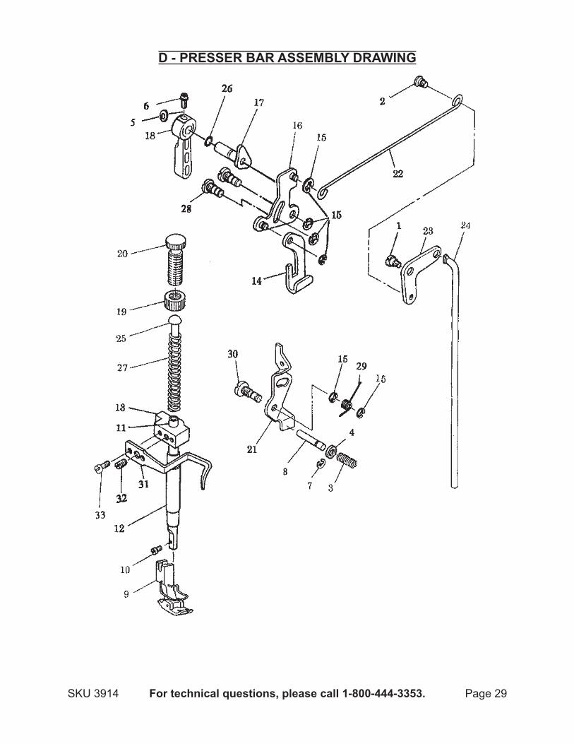
d - preSSer Bar aSSeMBly drawing
Page 30 For technical questions, please call 1-800-444-3353. SKU 3914
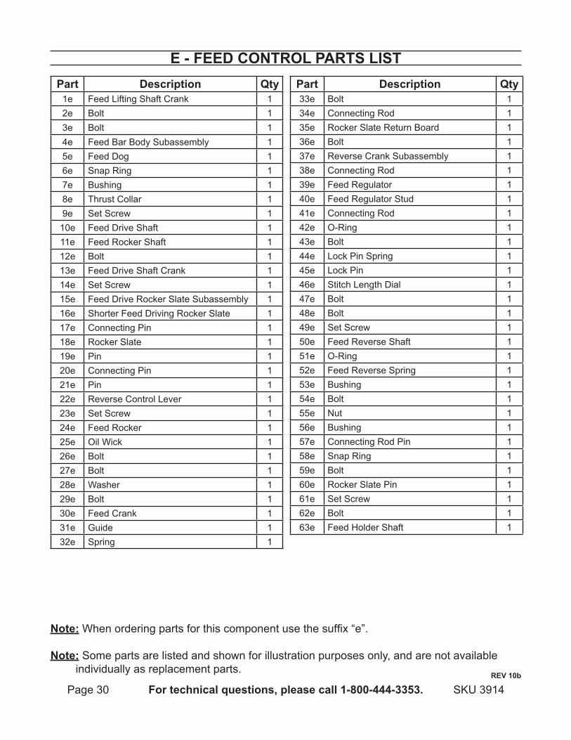
e - Feed cOntrOl partS liStpart description Qty
1e Feed Lifting Shaft Crank 12e Bolt 13e Bolt 14e Feed Bar Body Subassembly 15e Feed Dog 16e Snap Ring 17e Bushing 18e Thrust Collar 19e Set Screw 1
10e Feed Drive Shaft 111e Feed Rocker Shaft 112e Bolt 113e Feed Drive Shaft Crank 114e Set Screw 115e Feed Drive Rocker Slate Subassembly 116e Shorter Feed Driving Rocker Slate 117e Connecting Pin 118e Rocker Slate 119e Pin 120e Connecting Pin 121e Pin 122e Reverse Control Lever 123e Set Screw 124e Feed Rocker 125e Oil Wick 126e Bolt 127e Bolt 128e Washer 129e Bolt 130e Feed Crank 131e Guide 132e Spring 1
part description Qty33e Bolt 134e Connecting Rod 135e Rocker Slate Return Board 136e Bolt 137e Reverse Crank Subassembly 138e Connecting Rod 139e Feed Regulator 140e Feed Regulator Stud 141e Connecting Rod 142e O-Ring 143e Bolt 144e Lock Pin Spring 145e Lock Pin 146e Stitch Length Dial 147e Bolt 148e Bolt 149e Set Screw 150e Feed Reverse Shaft 151e O-Ring 152e Feed Reverse Spring 153e Bushing 154e Bolt 155e Nut 156e Bushing 157e Connecting Rod Pin 158e Snap Ring 159e Bolt 160e Rocker Slate Pin 161e Set Screw 162e Bolt 163e Feed Holder Shaft 1
note: When ordering parts for this component use the suffix “e”.
note: Some parts are listed and shown for illustration purposes only, and are not available individually as replacement parts.
reV 10b
Page 31For technical questions, please call 1-800-444-3353.SKU 3914
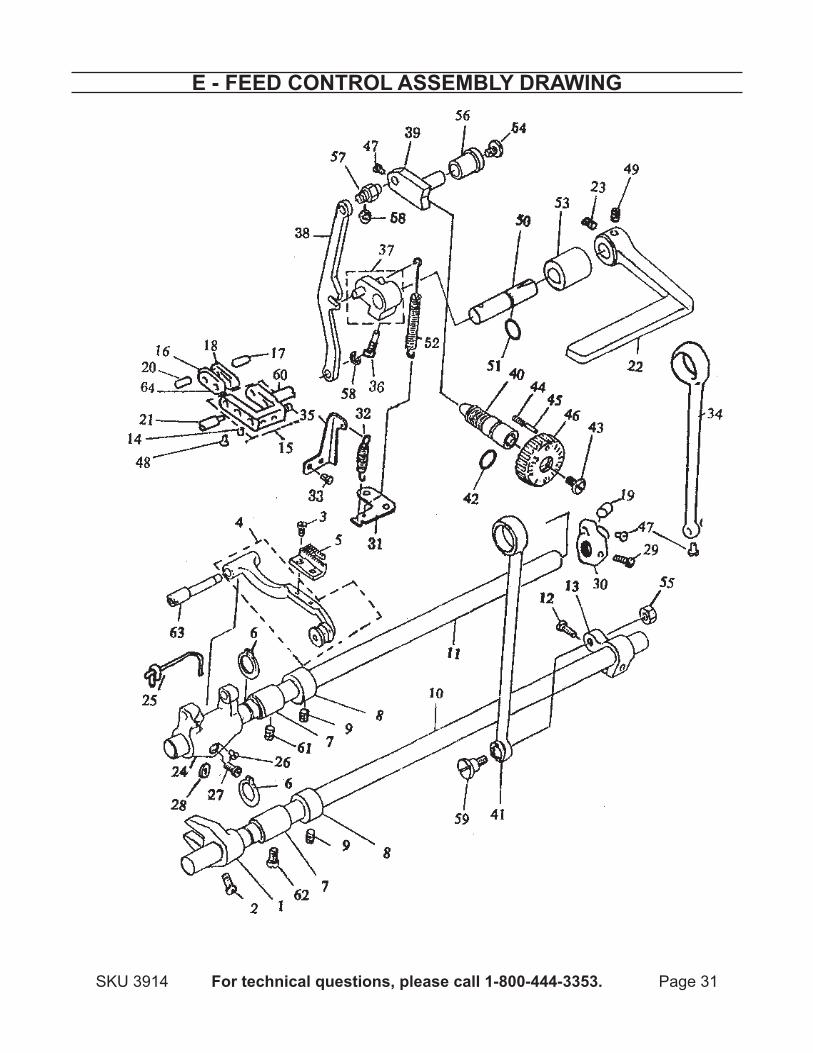
e - Feed cOntrOl aSSeMBly drawing
Page 32 For technical questions, please call 1-800-444-3353. SKU 3914
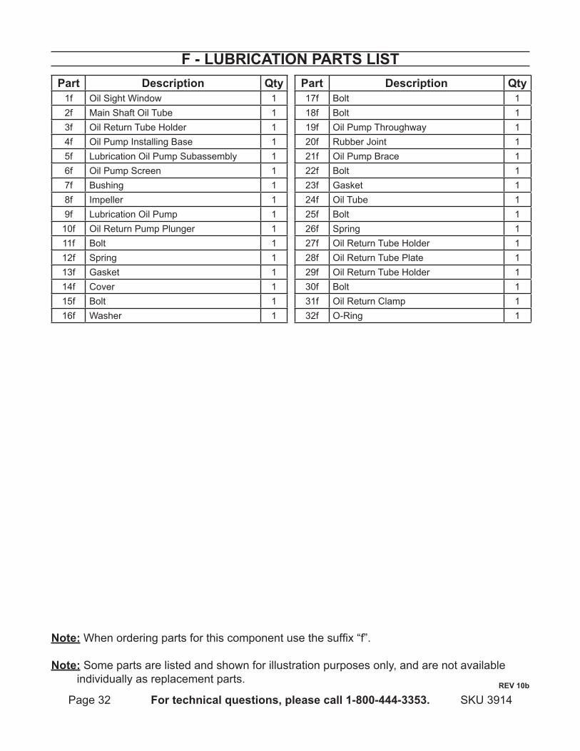
F - luBricatiOn partS liStpart description Qty
1f Oil Sight Window 12f Main Shaft Oil Tube 13f Oil Return Tube Holder 14f Oil Pump Installing Base 15f Lubrication Oil Pump Subassembly 16f Oil Pump Screen 17f Bushing 18f Impeller 19f Lubrication Oil Pump 1
10f Oil Return Pump Plunger 111f Bolt 112f Spring 113f Gasket 114f Cover 115f Bolt 116f Washer 1
part description Qty17f Bolt 118f Bolt 119f Oil Pump Throughway 120f Rubber Joint 121f Oil Pump Brace 122f Bolt 123f Gasket 124f Oil Tube 125f Bolt 126f Spring 127f Oil Return Tube Holder 128f Oil Return Tube Plate 129f Oil Return Tube Holder 130f Bolt 131f Oil Return Clamp 132f O-Ring 1
note: When ordering parts for this component use the suffix “f”.
note: Some parts are listed and shown for illustration purposes only, and are not available individually as replacement parts.
reV 10b
Page 33For technical questions, please call 1-800-444-3353.SKU 3914
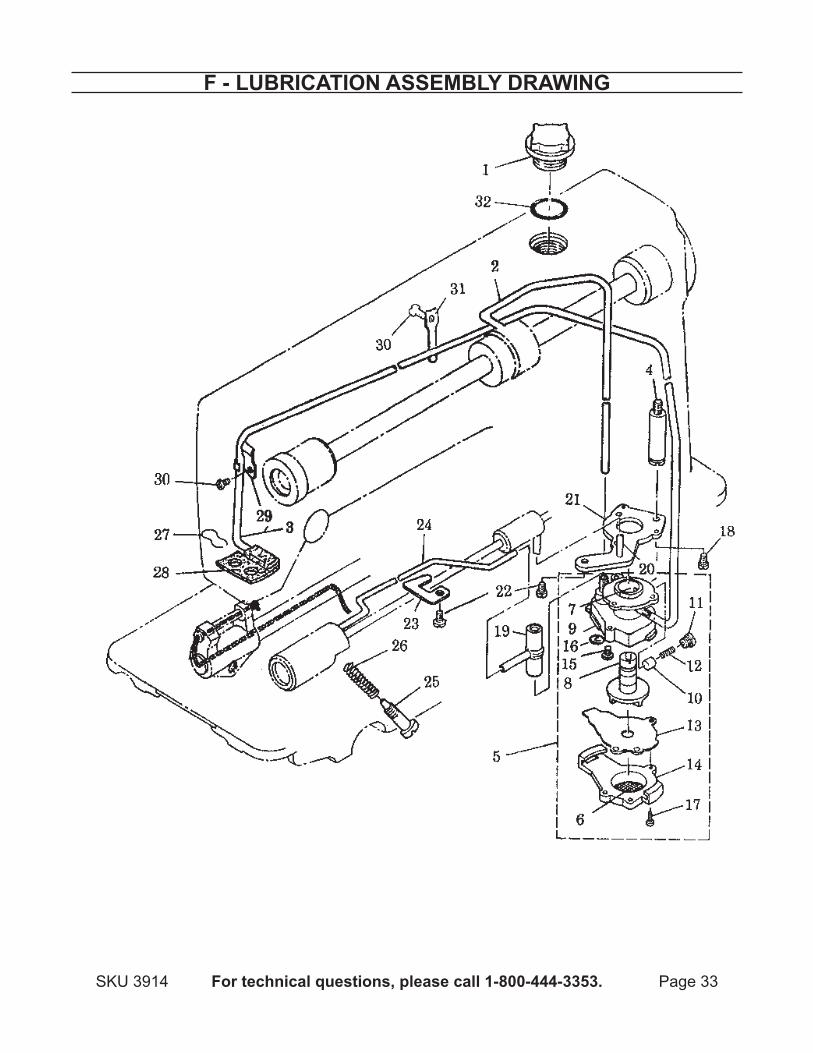
F - luBricatiOn aSSeMBly drawing
Page 34 For technical questions, please call 1-800-444-3353. SKU 3914
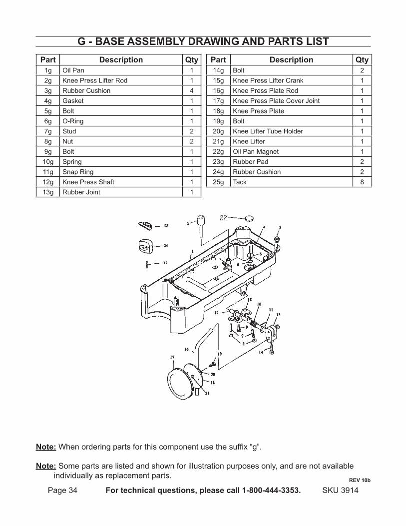
g - BaSe aSSeMBly drawing and partS liStpart description Qty
1g Oil Pan 12g Knee Press Lifter Rod 13g Rubber Cushion 44g Gasket 15g Bolt 16g O-Ring 17g Stud 28g Nut 29g Bolt 1
10g Spring 111g Snap Ring 112g Knee Press Shaft 113g Rubber Joint 1
part description Qty14g Bolt 215g Knee Press Lifter Crank 116g Knee Press Plate Rod 117g Knee Press Plate Cover Joint 118g Knee Press Plate 119g Bolt 120g Knee Lifter Tube Holder 121g Knee Lifter 122g Oil Pan Magnet 123g Rubber Pad 224g Rubber Cushion 225g Tack 8
note: When ordering parts for this component use the suffix “g”.
note: Some parts are listed and shown for illustration purposes only, and are not available individually as replacement parts.
reV 10b
Page 35For technical questions, please call 1-800-444-3353.SKU 3914
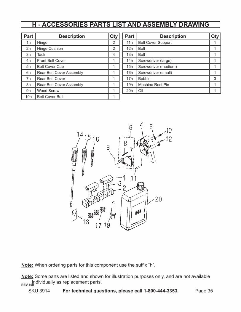
h - acceSSOrieS partS liSt and aSSeMBly drawing
part description Qty1h Hinge 22h Hinge Cushion 23h Tack 44h Front Belt Cover 15h Belt Cover Cap 16h Rear Belt Cover Assembly 17h Rear Belt Cover 18h Rear Belt Cover Assembly 19h Wood Screw 1
10h Belt Cover Bolt 1
part description Qty11h Belt Cover Support 112h Bolt 113h Bolt 114h Screwdriver (large) 115h Screwdriver (medium) 116h Screwdriver (small) 117h Bobbin 319h Machine Rest Pin 120h Oil 1
note: When ordering parts for this component use the suffix “h”.
note: Some parts are listed and shown for illustration purposes only, and are not available individually as replacement parts.
reV 10b
Page 36 For technical questions, please call 1-800-444-3353. SKU 3914
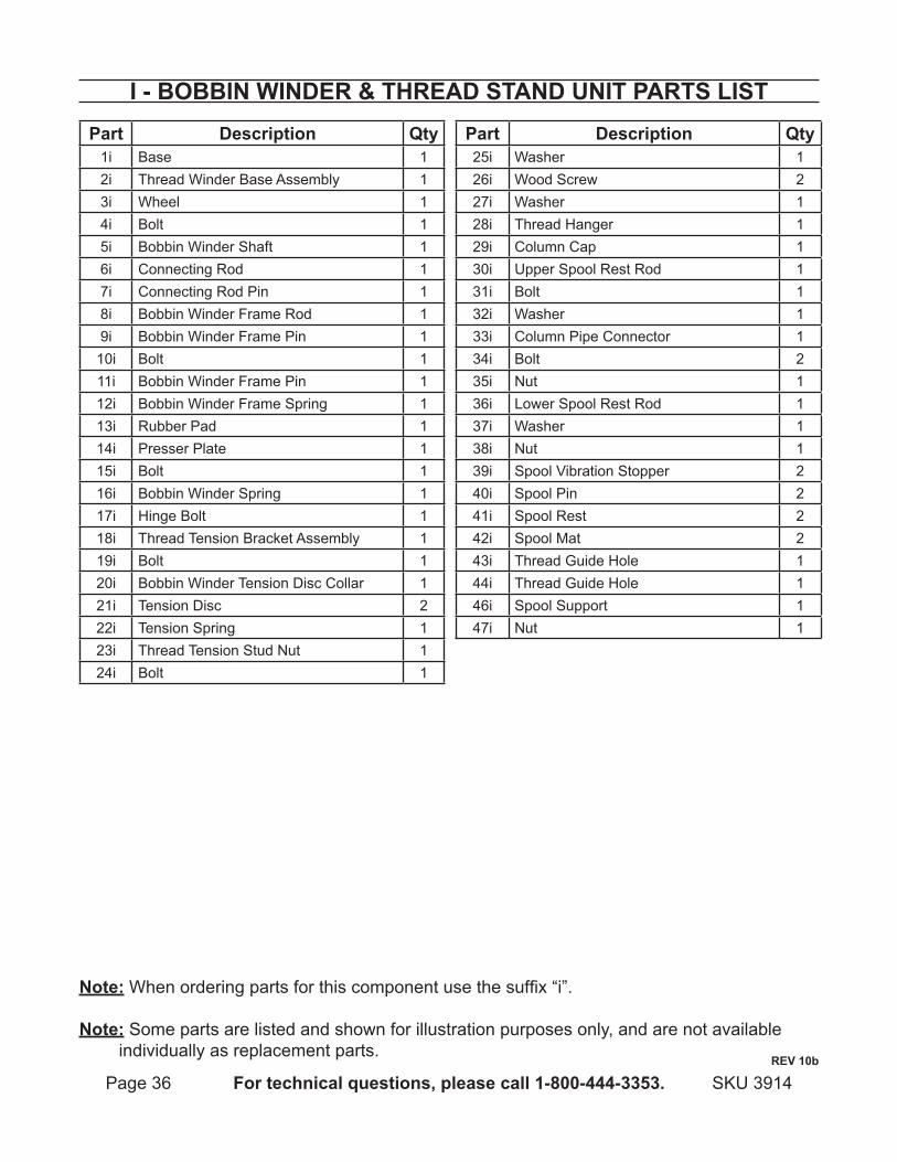
i - BOBBin winder & thread Stand unit partS liStpart description Qty
1i Base 12i Thread Winder Base Assembly 13i Wheel 14i Bolt 15i Bobbin Winder Shaft 16i Connecting Rod 17i Connecting Rod Pin 18i Bobbin Winder Frame Rod 19i Bobbin Winder Frame Pin 1
10i Bolt 111i Bobbin Winder Frame Pin 112i Bobbin Winder Frame Spring 113i Rubber Pad 114i Presser Plate 115i Bolt 116i Bobbin Winder Spring 117i Hinge Bolt 118i Thread Tension Bracket Assembly 119i Bolt 120i Bobbin Winder Tension Disc Collar 121i Tension Disc 222i Tension Spring 123i Thread Tension Stud Nut 124i Bolt 1
part description Qty25i Washer 126i Wood Screw 227i Washer 128i Thread Hanger 129i Column Cap 130i Upper Spool Rest Rod 131i Bolt 132i Washer 133i Column Pipe Connector 134i Bolt 235i Nut 136i Lower Spool Rest Rod 137i Washer 138i Nut 139i Spool Vibration Stopper 240i Spool Pin 241i Spool Rest 242i Spool Mat 243i Thread Guide Hole 144i Thread Guide Hole 146i Spool Support 147i Nut 1
note: When ordering parts for this component use the suffix “i”.
note: Some parts are listed and shown for illustration purposes only, and are not available individually as replacement parts.
reV 10b
Page 37For technical questions, please call 1-800-444-3353.SKU 3914
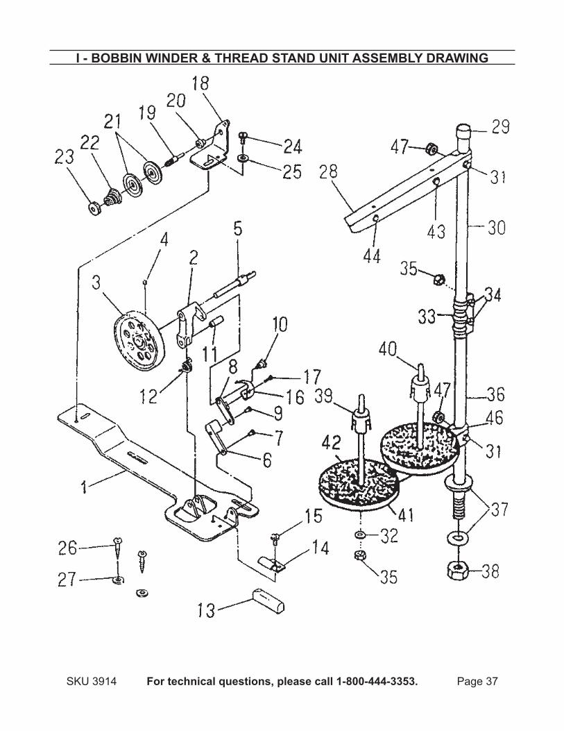
i - BOBBin winder & thread Stand unit aSSeMBly drawing
Page 38 For technical questions, please call 1-800-444-3353. SKU 3914
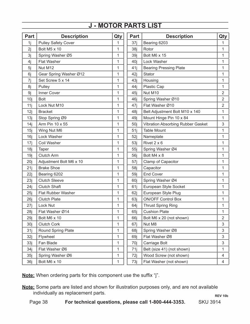
J - MOtOr partS liSt
note: When ordering parts for this component use the suffix “j”.
note: Some parts are listed and shown for illustration purposes only, and are not available individually as replacement parts.
reV 10b
part description Qty1j Pulley Safety Cover 12j Bolt M5 x 10 13j Spring Washer Ø5 14j Flat Washer 15j Nut M12 16j Gear Spring Washer Ø12 17j Set Screw 5 x 14 18j Pulley 19j Inner Cover 1
10j Bolt 111j Lock Nut M10 112j Bracket 113j Stop Spring Ø9 114j Arm Pin 10 x 55 115j Wing Nut M6 116j Lock Washer 117j Coil Washer 118j Taper 119j Clutch Arm 120j Adjustment Bolt M6 x 10 121j Brake Shoe 122j Bearing 6202 123j Clutch Sleeve 124j Clutch Shaft 125j Flat Rubber Washer 126j Clutch Plate 127j Lock Nut 128j Flat Washer Ø14 129j Bolt M6 x 10 130j Clutch Cork 131j Round Spring Plate 132j Flywheel 133j Fan Blade 134j Flat Washer Ø6 135j Spring Washer Ø6 136j Bolt M6 x 10 1
part description Qty37j Bearing 6203 138j Rotor 139j Bolt M6 x 15 140j Lock Washer 141j Bearing Pressing Plate 142j Stator 143j Housing 144j Plastic Cap 145j Nut M10 246j Spring Washer Ø10 247j Flat Washer Ø10 248j Belt Adjustment Bolt M10 x 140 149j Mount Hinge Pin 10 x 84 150j Vibration Absorbing Rubber Gasket 351j Table Mount 152j Nameplate 153j Rivet 2 x 6 155j Spring Washer Ø4 156j Bolt M4 x 8 157j Clamp of Capacitor 158j Capacitor 159j End Cover 160j Spring Washer Ø4 161j European Style Socket 162j European Style Plug 163j ON/OFF Control Box 164j Thrust Spring Ring 165j Cushion Plate 166j Bolt M6 x 20 (not shown) 267j Nut M8 368j Spring Washer Ø8 369j Flat Washer Ø8 370j Carriage Bolt 371j Belt (size 41) (not shown) 172j Wood Screw (not shown) 473j Flat Washer (not shown) 4
Page 39For technical questions, please call 1-800-444-3353.SKU 3914
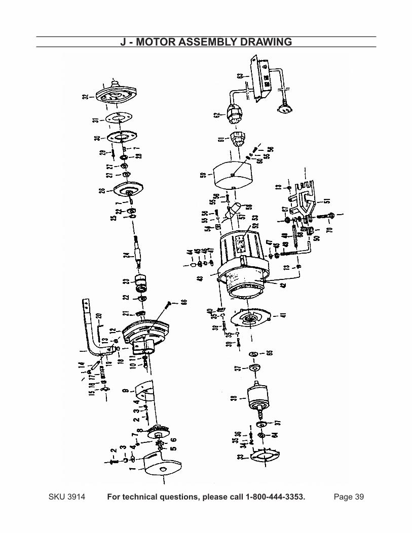
J - MOtOr aSSeMBly drawing
Page 40 For technical questions, please call 1-800-444-3353. SKU 3914
liMited 90 day warrantyHarbor Freight Tools Co. makes every effort to assure that its products meet high quality
and durability standards, and warrants to the original purchaser that this product is free from defects in materials and workmanship for the period of 90 days from the date of purchase. This warranty does not apply to damage due directly or indirectly, to misuse, abuse, negligence or accidents, repairs or alterations outside our facilities, criminal activity, improper installation, normal wear and tear, or to lack of maintenance. We shall in no event be liable for death, injuries to persons or property, or for incidental, contingent, special or consequential damages arising from the use of our product. Some states do not allow the exclusion or limitation of incidental or consequential damages, so the above limitation of exclusion may not apply to you. THIS WARRANTY IS EXPRESSLY IN LIEU OF ALL OTHER WARRANTIES, EXPRESS OR IMPLIED, INCLUDING THE WARRANTIES OF MERCHANTABILITY AND FITNESS.
To take advantage of this warranty, the product or part must be returned to us with transportation charges prepaid. Proof of purchase date and an explanation of the complaint must accompany the merchandise. If our inspection verifies the defect, we will either repair or replace the product at our election or we may elect to refund the purchase price if we cannot readily and quickly provide you with a replacement. We will return repaired products at our expense, but if we determine there is no defect, or that the defect resulted from causes not within the scope of our warranty, then you must bear the cost of returning the product.
This warranty gives you specific legal rights and you may also have other rights which vary from state to state.
3491 Mission Oaks Blvd. • PO Box 6009 • Camarillo, CA 93011 • (800) 444-3353
pleaSe read the FOllOwing careFullyTHE MANUFACTURER AND/OR DISTRIBUTOR HAS PROVIDED THE PARTS LIST AND ASSEMBLY DIAGRAM IN THIS MANUAL AS A REFERENCE TOOL ONLY. NEITHER THE MANUFACTURER OR DISTRIBUTOR MAKES ANY REPRESENTATION OR WARRANTY OF ANY KIND TO THE BUYER THAT HE OR SHE IS qUALIFIED TO MAKE ANY REPAIRS TO THE PRODUCT, OR THAT HE OR SHE IS qUALIFIED TO REPLACE ANY PARTS OF THE PRODUCT. IN FACT, THE MANUFACTURER AND/OR DISTRIBUTOR EXPRESSLY STATES THAT ALL REPAIRS AND PARTS REPLACEMENTS SHOULD BE UNDERTAKEN BY CERTIFIED AND LICENSED TECHNICIANS, AND NOT BY THE BUYER. THE BUYER ASSUMES ALL RISK AND LIABILITY ARISING OUT OF HIS OR HER REPAIRS TO THE ORIGINAL PRODUCT OR REPLACEMENT PARTS THERETO, OR ARISING OUT OF HIS OR HER INSTALLATION OF REPLACEMENT PARTS THERETO.


![1-NEEDLE LOCKSTITCH SEWING MACHINE WITH AUTOMATIC …€¦ · 1-NEEDLE LOCKSTITCH SEWING MACHINE WITH AUTOMATIC THREAD TRIMMER FOR PROFESSIONAL No.00 40175681. CONTENTS [1] SPECIFICATIONS](https://img.pdfslide.net/doc/110x75/6071735a1556115d42165cf8/1-needle-lockstitch-sewing-machine-with-automatic-1-needle-lockstitch-sewing-machine.jpg)