Embed Size (px)
Citation preview
© Festo Didactic 86359-00 25
When you have completed this exercise, you will be familiar with the operation of the single-phase PWM inverter.
The Discussion of this exercise covers the following points:
Using a four-quadrant chopper as an inverter
Relationship between the output voltage, input voltage, and modulation index in a single-phase PWM inverter
Using a four-quadrant chopper as an inverter
Inverters are devices which convert dc power into ac power. This allows single-phase and three-phase ac power systems with variable frequency and voltage to be obtained. For instance, three-phase inverters are widely used to build ac motor drives, while single-phase inverters are often used to power household appliances from energy produced by solar panels or wind turbines and stored in a battery or a battery bank.
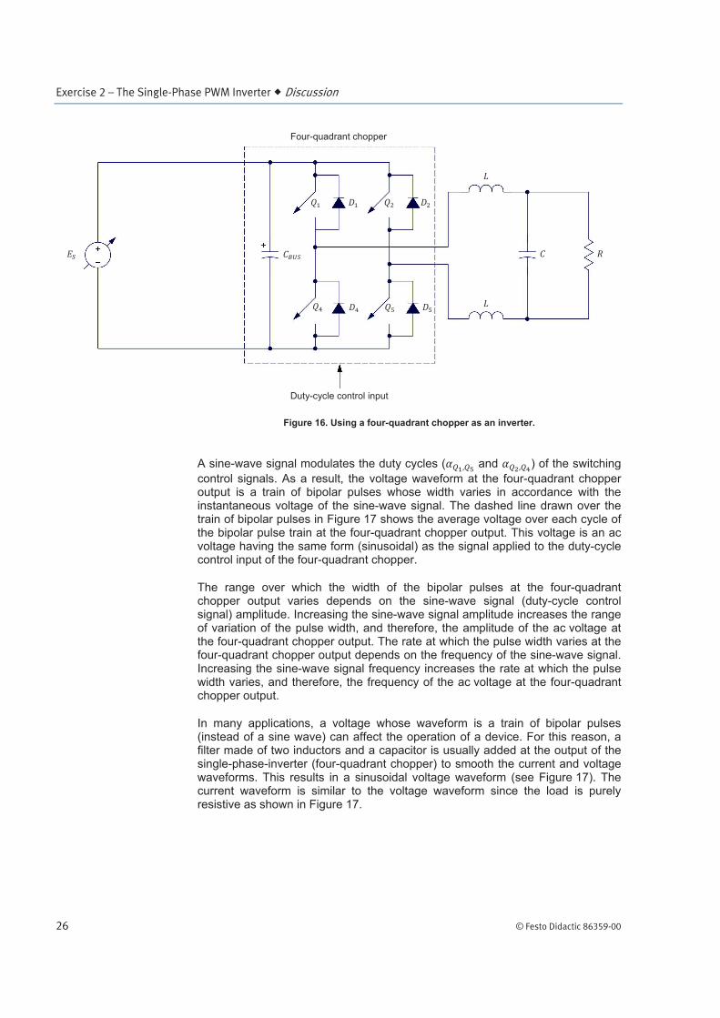
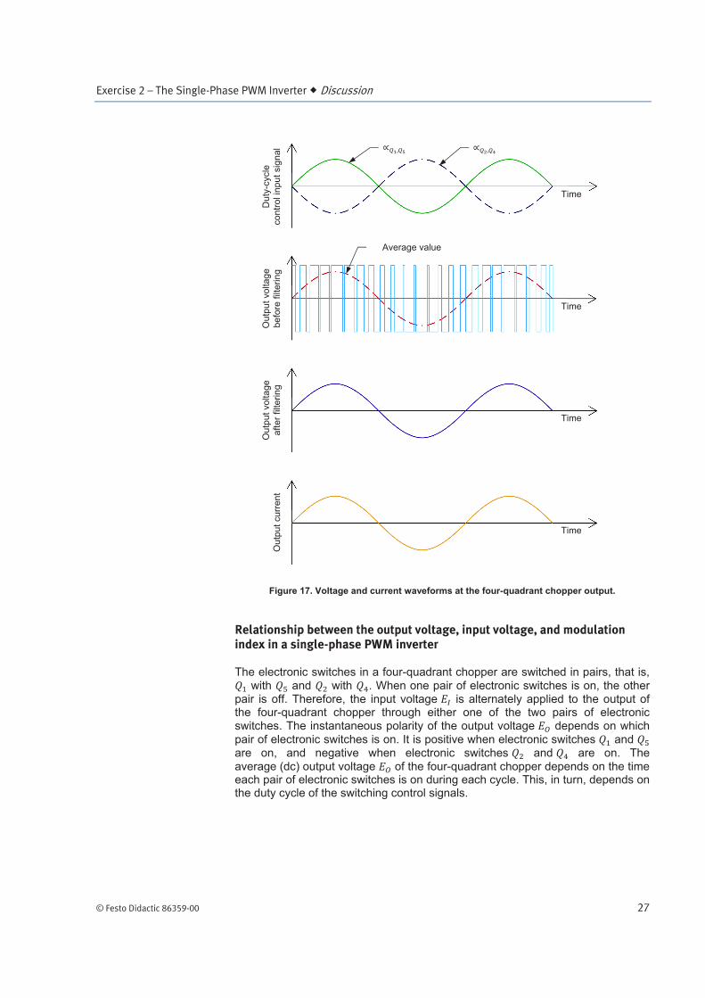
A single-phase inverter can be implemented using a four-quadrant chopper. In this situation, the duty cycle of the switching control signals is made to vary so that the voltage at the chopper output alternates at a given rate between positive and negative values. Figure 16 shows a four-quadrant chopper connected to a resistive load. Figure 17 shows the waveform of the signal applied at the duty-cycle control input of the four-quadrant chopper, and the waveforms of the voltage (before and after filtering) and current at the four-quadrant chopper output.
The Single-Phase PWM Inverter
Exercise 2
EXERCISE OBJECTIVE
DISCUSSION OUTLINE
DISCUSSION
Exercise 2 – The Single-Phase PWM Inverter Discussion
26 © Festo Didactic 86359-00
Figure 16. Using a four-quadrant chopper as an inverter.
A sine-wave signal modulates the duty cycles ( and ) of the switching
control signals. As a result, the voltage waveform at the four-quadrant chopper output is a train of bipolar pulses whose width varies in accordance with the instantaneous voltage of the sine-wave signal. The dashed line drawn over the train of bipolar pulses in Figure 17 shows the average voltage over each cycle of the bipolar pulse train at the four-quadrant chopper output. This voltage is an ac voltage having the same form (sinusoidal) as the signal applied to the duty-cycle control input of the four-quadrant chopper.
The range over which the width of the bipolar pulses at the four-quadrant chopper output varies depends on the sine-wave signal (duty-cycle control signal) amplitude. Increasing the sine-wave signal amplitude increases the range of variation of the pulse width, and therefore, the amplitude of the ac voltage at the four-quadrant chopper output. The rate at which the pulse width varies at the four-quadrant chopper output depends on the frequency of the sine-wave signal. Increasing the sine-wave signal frequency increases the rate at which the pulse width varies, and therefore, the frequency of the ac voltage at the four-quadrant chopper output.
In many applications, a voltage whose waveform is a train of bipolar pulses (instead of a sine wave) can affect the operation of a device. For this reason, a filter made of two inductors and a capacitor is usually added at the output of the single-phase-inverter (four-quadrant chopper) to smooth the current and voltage waveforms. This results in a sinusoidal voltage waveform (see Figure 17). The current waveform is similar to the voltage waveform since the load is purely resistive as shown in Figure 17.
Four-quadrant chopper
Duty-cycle control input
Exercise 2 – The Single-Phase PWM Inverter Discussion
© Festo Didactic 86359-00 27
Figure 17. Voltage and current waveforms at the four-quadrant chopper output.
Relationship between the output voltage, input voltage, and modulation index in a single-phase PWM inverter
The electronic switches in a four-quadrant chopper are switched in pairs, that is,
with and with . When one pair of electronic switches is on, the other pair is off. Therefore, the input voltage is alternately applied to the output of the four-quadrant chopper through either one of the two pairs of electronic switches. The instantaneous polarity of the output voltage depends on which
pair of electronic switches is on. It is positive when electronic switches and are on, and negative when electronic switches and are on. The
average (dc) output voltage of the four-quadrant chopper depends on the time each pair of electronic switches is on during each cycle. This, in turn, depends on the duty cycle of the switching control signals.
Du
ty-c
ycle
co
ntr
ol in
pu
t sig
na
l
Time
Time
Ou
tpu
t vo
lta
ge
be
fore
filt
eri
ng
Ou
tpu
t vo
lta
ge
aft
er
filte
rin
g
Ou
tpu
t cu
rre
nt
Time
Time
Average value
Exercise 2 – The Single-Phase PWM Inverter Discussion
28 © Festo Didactic 86359-00
The equation relating voltages and is written below.
(1)
where is the dc voltage at the four-quadrant chopper output.
is the dc voltage at the four-quadrant chopper input.
is the duty cycle of electronic switches and , expressed as a decimal.
Since the duty cycle can vary from approximately 0 to 1, the voltage can vary from approximately - to + .
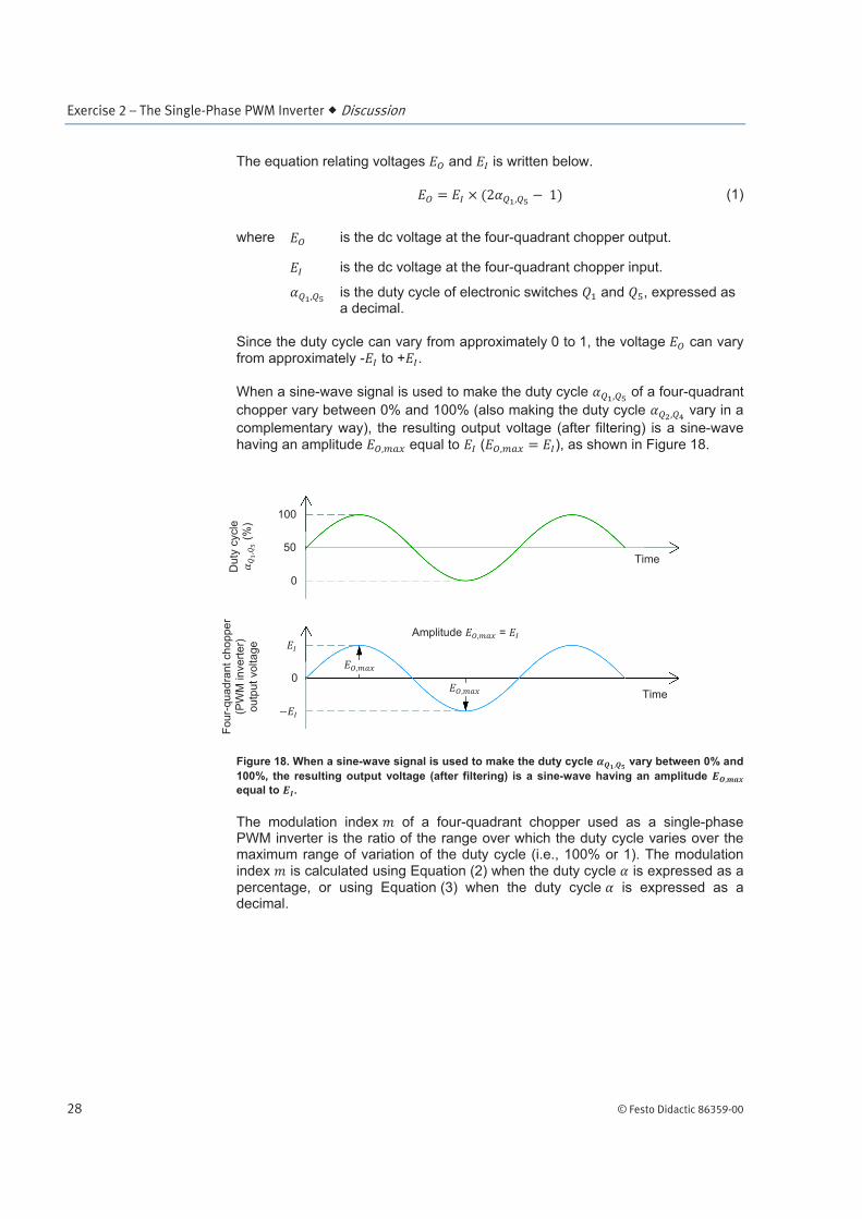
When a sine-wave signal is used to make the duty cycle of a four-quadrant
chopper vary between 0% and 100% (also making the duty cycle vary in a
complementary way), the resulting output voltage (after filtering) is a sine-wave
having an amplitude equal to ( ), as shown in Figure 18.
Figure 18. When a sine-wave signal is used to make the duty cycle vary between 0% and
100%, the resulting output voltage (after filtering) is a sine-wave having an amplitude
equal to .
The modulation index of a four-quadrant chopper used as a single-phase PWM inverter is the ratio of the range over which the duty cycle varies over the maximum range of variation of the duty cycle (i.e., 100% or 1). The modulation index is calculated using Equation (2) when the duty cycle is expressed as a
percentage, or using Equation (3) when the duty cycle is expressed as a decimal.
100
50
0
0
Amplitude =
Time
Time
Du
ty c
ycle
(%
)
Fo
ur-
qu
ad
ran
t ch
op
pe
r
(PW
M in
ve
rter)
ou
tpu
t vo
lta
ge
Exercise 2 – The Single-Phase PWM Inverter Discussion
© Festo Didactic 86359-00 29
(2)
where is the modulation index (pure number).
is the maximum value of the duty cycle, expressed as a percentage.
is the minimum value of the duty cycle, expressed as a percentage.
(3)
where is the modulation index (pure number).
is the maximum value of the duty cycle, expressed as a decimal.
is the minimum value of the duty cycle, expressed as a decimal.
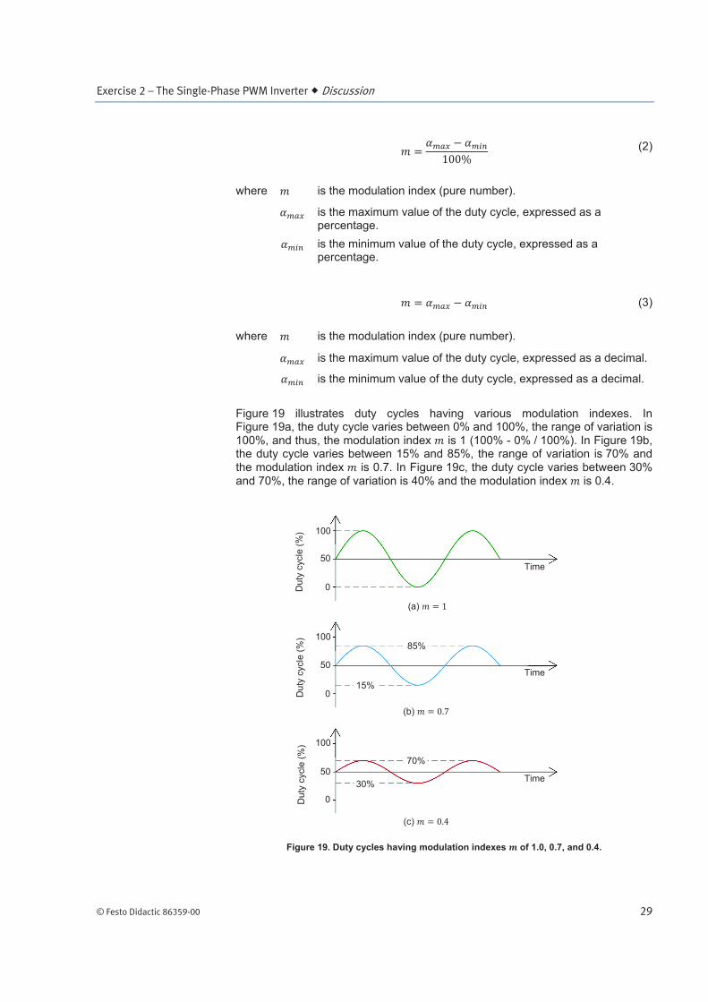
Figure 19 illustrates duty cycles having various modulation indexes. In Figure 19a, the duty cycle varies between 0% and 100%, the range of variation is
100%, and thus, the modulation index is 1 (100% - 0% / 100%). In Figure 19b, the duty cycle varies between 15% and 85%, the range of variation is 70% and the modulation index is 0.7. In Figure 19c, the duty cycle varies between 30%
and 70%, the range of variation is 40% and the modulation index is 0.4.
Figure 19. Duty cycles having modulation indexes of 1.0, 0.7, and 0.4.
100
50
0
100
50
0
100
50
0
Du
ty c
ycle
(%
) D
uty
cycle
(%
) D
uty
cycle
(%
)
85%
15%
70%
30%
(c)
(b)
(a)
Time
Time
Time
Exercise 2 – The Single-Phase PWM Inverter Discussion
30 © Festo Didactic 86359-00
When a four-quadrant chopper is used as a single-phase PWM inverter, the
amplitude of the voltage sine wave at the inverter output depends on both
the input voltage and the modulation index . The amplitude of the
voltage sine wave at the single-phase PWM inverter output can be calculated using the following equation:
(4)
where is the amplitude of the voltage sine wave at the single-phase
PWM inverter output (four-quadrant chopper output), expressed in V.
is the average (dc) voltage at the single-phase PWM inverter input (four-quadrant chopper input), expressed in V.
is the modulation index (pure number).
Equation (5) shows how the above equation can be modified to calculate the rms value of the voltage sine wave at the single-phase PWM inverter output.
(5)
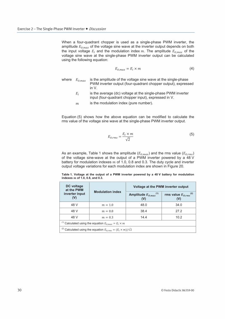
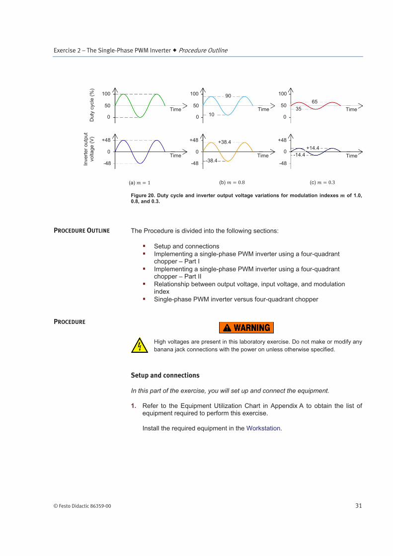
As an example, Table 1 shows the amplitude ( ) and the rms value ( )
of the voltage sine-wave at the output of a PWM inverter powered by a 48 V
battery for modulation indexes of 1.0, 0.8 and 0.3. The duty cycle and inverter output voltage variations for each modulation index are shown in Figure 20.
Table 1. Voltage at the output of a PWM inverter powered by a 48 V battery for modulation
indexes of 1.0, 0.8, and 0.3.
DC voltage at the PWM
inverter input (V)
Modulation index
Voltage at the PWM inverter output
Amplitude (1)
(V)
rms value (2)
(V)
48 V 48.0 34.0
48 V 38.4 27.2
48 V 14.4 10.2
(1) Calculated using the equation
(2) Calculated using the equation
Exercise 2 – The Single-Phase PWM Inverter Procedure Outline
© Festo Didactic 86359-00 31
Figure 20. Duty cycle and inverter output voltage variations for modulation indexes of 1.0, 0.8, and 0.3.
The Procedure is divided into the following sections:
Setup and connections
Implementing a single-phase PWM inverter using a four-quadrant chopper – Part I
Implementing a single-phase PWM inverter using a four-quadrant chopper – Part II
Relationship between output voltage, input voltage, and modulation index
Single-phase PWM inverter versus four-quadrant chopper
High voltages are present in this laboratory exercise. Do not make or modify any
banana jack connections with the power on unless otherwise specified.
Setup and connections
In this part of the exercise, you will set up and connect the equipment.
1. Refer to the Equipment Utilization Chart in Appendix A to obtain the list of equipment required to perform this exercise.
Install the required equipment in the Workstation.
PROCEDURE OUTLINE
PROCEDURE
Time
Time
Time
Time
Time
Time
Du
ty c
ycle
(%
) 100
50
0
100
50
0
100
50
0
+48
-48
0
+48
-48
0
+48
0
-48
(a) (b) (c)
Inve
rte
r o
utp
ut
vo
lta
ge
(V
) 90
1035
65
+38.4
-38.4
+14.4
-14.4
Exercise 2 – The Single-Phase PWM Inverter Procedure
32 © Festo Didactic 86359-00
2. Connect the Power Input of the Data Acquisition and Control Interface to a 24 V ac power supply.
Connect the Low Power Input of the IGBT Chopper/Inverter to the Power Input of the Data Acquisition and Control Interface. Turn the 24 V ac power supply on.
3. Connect the USB port of the Data Acquisition and Control Interface to a USB port of the host computer.
Connect the USB port of the Four-Quadrant Dynamometer/Power Supply to a USB port of the host computer.
4. Make sure that the main power switch of the Four-Quadrant Dynamometer/ Power Supply is set to O (off), then connect the Power Input to an ac power outlet.
Set the Operating Mode switch of the Four-Quadrant Dynamometer/Power Supply to Power Supply.
Turn the Four-Quadrant Dynamometer/Power Supply on by setting the main power switch to I (on).
5. Turn the host computer on, then start the LVDAC-EMS software.
In the LVDAC-EMS Start-Up window, make sure that the Data Acquisition and Control Interface is detected. Make sure that the Computer-Based Instrumentation and Chopper/Inverter Control functions for the Data Acquisition and Control Interface are available. Select the network voltage and frequency that correspond to the voltage and frequency of your local ac power network, then click the OK button to close the LVDAC-EMS Start-Up window.
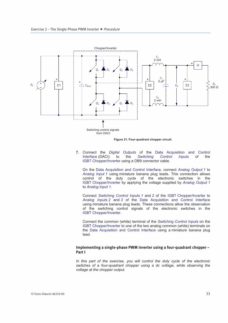
6. Set up the circuit shown in Figure 21. Use the two 2 mH inductors and the 5 F capacitor of the Filtering Inductors/Capacitors module to implement ,
, and . Make the necessary connections and switch settings on the Resistive Load in order to obtain the resistance value required.
Exercise 2 – The Single-Phase PWM Inverter Procedure
© Festo Didactic 86359-00 33
Figure 21. Four-quadrant chopper circuit.
7. Connect the Digital Outputs of the Data Acquisition and Control Interface (DACI) to the Switching Control Inputs of the IGBT Chopper/Inverter using a DB9 connector cable.
On the Data Acquisition and Control Interface, connect Analog Output 1 to Analog Input 1 using miniature banana plug leads. This connection allows control of the duty cycle of the electronic switches in the IGBT Chopper/Inverter by applying the voltage supplied by Analog Output 1 to Analog Input 1.
Connect Switching Control Inputs 1 and 2 of the IGBT Chopper/Inverter to Analog Inputs 2 and 3 of the Data Acquisition and Control Interface using miniature banana plug leads. These connections allow the observation of the switching control signals of the electronic switches in the IGBT Chopper/Inverter.
Connect the common (white) terminal of the Switching Control Inputs on the IGBT Chopper/Inverter to one of the two analog common (white) terminals on the Data Acquisition and Control Interface using a miniature banana plug lead.
Implementing a single-phase PWM inverter using a four-quadrant chopper – Part I
In this part of the exercise, you will control the duty cycle of the electronic switches of a four-quadrant chopper using a dc voltage, while observing the voltage at the chopper output.
300
2 mH
Switching control signals from DACI
Chopper/Inverter
5 µF
2 mH
Exercise 2 – The Single-Phase PWM Inverter Procedure
34 © Festo Didactic 86359-00
8. In LVDAC-EMS, open the Four-Quadrant Dynamometer/Power Supply window and make the following settings:
Select the Voltage Source (+) function.
Set the Voltage parameter to 100 V.
Start the voltage source.
9. In LVDAC-EMS, open the Chopper/Inverter Control window and make the following settings:
Select the Four-Quadrant Chopper function.
Set the Switching Frequency parameter to 2000 Hz.
Set the Duty Cycle Control parameter to AI-1 (-10 to 10 V). This setting allows control of the duty cycle of the electronic switches in the four-quadrant chopper using a dc voltage applied to Analog Input 1.
Make sure that the acceleration time is set to 0.0 s.
Make sure that the deceleration time is set to 0.0 s.
Make sure that the , , , and parameters are set to PWM.
Start the four-quadrant chopper.
10. In LVDAC-EMS, open the Oscilloscope window and use channels 1 to 7 to display the duty-cycle control voltage (AI-1), the switching control signals of
electronic switches (AI-2) and (AI-3), the dc voltage at the input of the inverter (E1), the voltage at the inverter output before
filtering (E2) and after filtering (E3), and the current flowing through the load (I1), respectively.
Select the Continuous Refresh mode, set the time base to 0.2 ms/div, and set the trigger controls so that the Oscilloscope triggers when the rising edge
of the switching control signal (AI-2) of electronic switches , reaches 2 V.
Select convenient vertical scale and position settings to facilitate observation of the waveforms.
11. In LVDAC-EMS, open the Analog Output 1 window. The analog outputs in LVDAC-EMS can be used to control various parameters such as voltage, current, speed, torque, frequency, ratio (duty cycle), and firing angle by producing a voltage that can varied between -10 V and +10 V. The correspondence between the controlled parameter and the voltage output is defined in the Analog Output windows.
Exercise 2 – The Single-Phase PWM Inverter Procedure
© Festo Didactic 86359-00 35
In the Analog Output 1 window, make the following settings:
Set the Function parameter to Command Button. This setting allows the voltage at Analog Output 1 to be set between -10 V and +10 V, using a control knob, arrow buttons, or by entering the desired value directly in the Analog Output Settings.
Set the Command Name parameter to Voltage. This sets the type of command that you are controlling. In the present case, the command you are controlling is the voltage used to control the duty cycle of the four-quadrant chopper.
Set the Max Command parameter to 10. This sets the maximum value for the command you are controlling. In the present case, the maximum voltage command that can be reached is 10 V.
Set the Voltage Corresponding to Max Command parameter to 10. This sets the voltage at the analog output corresponding to the Max Command parameter value that you set. In the present case, a voltage equal to 10 V at Analog Output 1 corresponds to a voltage command of 10 V.
Set the Min Command (V) parameter to -10. This sets the minimum value for the command you are controlling. In the present case, the minimum voltage command that can be reached is -10 V.
Make sure that the Voltage Corresponding to Min Command (V) is set to -10. This sets the voltage at the analog output corresponding to the Min Command parameter value you have set. In the present case, a voltage equal to -10 V at Analog Output 1 corresponds to a voltage command of -10 V.
Set the Command Step parameter to 1. This sets the increment corresponding to one click on the arrow buttons located under the control knob. In the present case, the voltage (command) increases by 1 V each time the up-arrow button is clicked, or decreases by 1 V each time the down-arrow button is clicked.
Set the Voltage parameter to -10. This sets the voltage at Analog Output 1 to -10 V.
a The value of the Voltage parameter and the voltage at Analog Output 1 are identical in the present case because the command type is voltage and because the values of the parameters "Voltage Corresponding to Min Command" and "Min Command" are equal. Note that if the command type were a speed command as an example, the Voltage parameter would become the Speed parameter and would set the number of revolutions per minute corresponding to the voltage at Analog Output 1.
These settings will allow you to produce a voltage variable between -10 V and +10 V at Analog Output 1 (currently set to -10 V). This voltage is used to control the duty-cycle of the electronic switches in the four-quadrant chopper.
Exercise 2 – The Single-Phase PWM Inverter Procedure
36 © Festo Didactic 86359-00
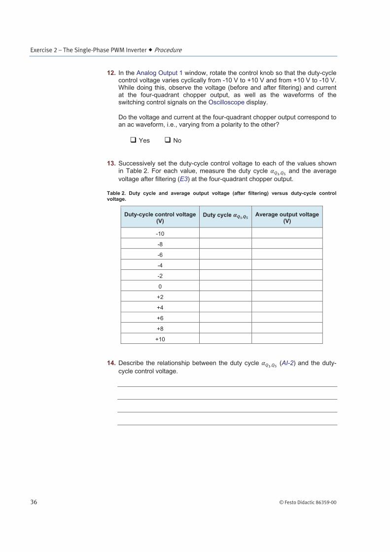
12. In the Analog Output 1 window, rotate the control knob so that the duty-cycle control voltage varies cyclically from -10 V to +10 V and from +10 V to -10 V. While doing this, observe the voltage (before and after filtering) and current at the four-quadrant chopper output, as well as the waveforms of the switching control signals on the Oscilloscope display.
Do the voltage and current at the four-quadrant chopper output correspond to an ac waveform, i.e., varying from a polarity to the other?
Yes No
13. Successively set the duty-cycle control voltage to each of the values shown in Table 2. For each value, measure the duty cycle and the average
voltage after filtering (E3) at the four-quadrant chopper output.
Table 2. Duty cycle and average output voltage (after filtering) versus duty-cycle control voltage.
Duty-cycle control voltage (V)
Duty cycle Average output voltage (V)
-10
-8
-6
-4
-2
0
+2
+4
+6
+8
+10
14. Describe the relationship between the duty cycle (AI-2) and the duty-
cycle control voltage.

Exercise 2 – The Single-Phase PWM Inverter Procedure
© Festo Didactic 86359-00 37
15. Describe the relationship between the average voltage at the four-quadrant chopper output and the duty-cycle control voltage.
16. From your observations, is it possible to convert dc power into ac power using a four-quadrant chopper? If so, explain how.
17. Stop the voltage source and the four-quadrant chopper.
Implementing a single-phase PWM inverter using a four-quadrant chopper – Part II
In this part of the exercise, you will control the duty cycle of the electronic switches of a four-quadrant chopper using a sinusoidal duty-cycle control voltage while observing the voltage at the chopper output.
18. In the Analog Output 1 window, make the following settings:
Set the Function parameter to Function Generator. This setting makes the output signal of a function generator available at Analog Output 1. The function generator can produce various voltage waveforms such as sine, square, triangle, and sawtooth.
Set the Waveform parameter to Sine. This sets the function generator to produce a sine wave.
Set the Frequency parameter to 1 Hz. This sets the frequency of the sine wave to 1 Hz.
Set the Amplitude parameter to 10 V. This sets the amplitude of the sine wave to 10 V.
Start the function generator.
These settings will produce a sinusoidal voltage varying slowly between -10 V and +10 V at Analog Output 1. This voltage will be used to control the duty cycle of the electronic switches in the four-quadrant chopper.
Exercise 2 – The Single-Phase PWM Inverter Procedure
38 © Festo Didactic 86359-00
19. Describe how the duty cycle will be affected by the duty-cycle control
voltage produced by the function generator.
20. In the main window of LVDAC-EMS, set the range of E3 to High.
21. Start the voltage source and the four-quadrant chopper.
In the Oscilloscope window, set the time base to 0.2 s/div.
Does the duty cycle vary as predicted in the previous step?
Yes No
22. Observe the voltage (after filtering) at the four-quadrant output on the Oscilloscope display. Describe what happens.
23. In the Analog Output 1 window, gradually increase the frequency of the duty-cycle control voltage up to 10 Hz while observing the voltage (after filtering) at the four-quadrant chopper output on the Oscilloscope display. Describe what happens.
24. In the Analog Output 1 window, set the frequency of the duty-cycle control signal to the frequency of your local ac power network. Set the amplitude of the control signal to 8 V.
In the Oscilloscope window, set the time base to 5 ms/div, and set the trigger controls so that the Oscilloscope triggers when the rising edge of the duty-cycle control signal (AI-1) of the four-quadrant chopper reaches 0 V.
Exercise 2 – The Single-Phase PWM Inverter Procedure
© Festo Didactic 86359-00 39
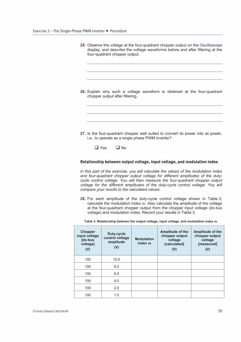
25. Observe the voltage at the four-quadrant chopper output on the Oscilloscope display, and describe the voltage waveforms before and after filtering at the four-quadrant chopper output.
26. Explain why such a voltage waveform is obtained at the four-quadrant chopper output after filtering.
27. Is the four-quadrant chopper well suited to convert dc power into ac power, i.e., to operate as a single phase PWM inverter?
Yes No
Relationship between output voltage, input voltage, and modulation index
In this part of the exercise, you will calculate the values of the modulation index and four-quadrant chopper output voltage for different amplitudes of the duty-cycle control voltage. You will then measure the four-quadrant chopper output voltage for the different amplitudes of the duty-cycle control voltage. You will compare your results to the calculated values.
28. For each amplitude of the duty-cycle control voltage shown in Table 3,
calculate the modulation index . Also calculate the amplitude of the voltage at the four-quadrant chopper output from the chopper input voltage (dc-bus voltage) and modulation index. Record your results in Table 3.
Table 3. Relationship between the output voltage, input voltage, and modulation index .
Chopper input voltage
[dc-bus voltage]
(V)
Duty-cycle control voltage
amplitude
(V)
Modulation
index
Amplitude of the chopper output
voltage [calculated]
(V)
Amplitude of the chopper output
voltage [measured]
(V)
100 10.0
100 8.0
100 6.0
100 4.0
100 2.0
100 1.0
Exercise 2 – The Single-Phase PWM Inverter Procedure
40 © Festo Didactic 86359-00
29. In the Analog Output 1 window, successively set the duty-cycle control voltage to each amplitude shown in Table 3. For each value, measure the amplitude of the chopper output voltage (after filtering) and record the
values in the table.
Are the amplitudes of the voltage measured at the four-quadrant chopper
output equal to the calculated values, confirming that ?
Yes No
30. Stop the voltage source and the four-quadrant chopper.
Single-phase PWM inverter versus four-quadrant chopper
In this part of the exercise, you will compare the voltage and current waveforms of the four-quadrant chopper to those of the single-phase PWM inverter.
31. In the Chopper/Inverter Control window, set the switching frequency to 20 000 Hz. (Do not modify the setting of the other parameters in this window.)
32. In the Analog Output 1 window, set the amplitude of the duty-cycle control
voltage to 8.0 V to obtain a modulation index of 0.8.
33. Start the voltage source and the four-quadrant chopper.
34. In the Oscilloscope window, make the following settings:
In the Oscilloscope Settings, set the Acquisition Filtering parameter to On.
Turn off Channels 1, 2, 3, 4, and 5, leaving only Channels 6 and 7 on to observe the four-quadrant chopper output voltage (after filtering) and current.
Make sure that the Continuous Refresh mode is selected, set the time base to 5 ms/div, and set the trigger controls so that the Oscilloscope triggers when the chopper output current (I-1) passes through 0 V with a positive slope.
Select convenient vertical scale and position settings to facilitate observation of the voltage and current at the four-quadrant chopper output (Channels 6, and 7).
Record the waveforms in memory M1.
Exercise 2 – The Single-Phase PWM Inverter Procedure
© Festo Didactic 86359-00 41
35. Open the Harmonic Analyzer window and make the following settings:
Select Network as Type of fundamental frequency. This setting allows the total harmonic distortion of the four-quadrant chopper output voltage (after filtering) to be determined at the local network frequency.
Select E3 as input. This setting determines the signal to analyze.
Select % of 1f as Type of scale to display. With this setting, the total harmonic distortion is displayed in % of the signal fundamental frequency in the Harmonic Analyzer window.
36. Enter the total harmonic distortion (THD) of the voltage at the output of the four-quadrant chopper shown in the Distortion [%] section in the Harmonic Analyzer window.
Total harmonic distortion THD: _____
37. Observe the output voltage waveform of the four-quadrant chopper displayed on the Oscilloscope. Can you conclude that the waveform is closed to a pure sine wave?
Yes No
38. Stop the four-quadrant chopper.
39. On the Data Acquisition and Control Interface, disconnect Analog Output 1 from Analog Input 1.
40. In the Chopper/Inverter Control window, select the Single-Phase, PWM Inverter function.
Observe the schematic diagram, and note that the single-phase PWM inverter is in fact a four quadrant chopper.
Make the following settings in the Chopper/Inverter Control window:
Make sure that the Switching Frequency parameter is set to 20 000 Hz.
Make sure that the DC Bus parameter is set to Unipolar. This setting indicates that the dc bus of the Chopper/Inverter is supplied by a unipolar dc voltage source.
Set the Frequency parameter to the frequency of your local ac power network.
Set the Peak Voltage (% of DC Bus/2) parameter to 80. This setting
determines the modulation index . In the present case, this sets the modulation index to 0.8.
Exercise 2 – The Single-Phase PWM Inverter Conclusion
42 © Festo Didactic 86359-00
a For comparison purposes, these parameters are set to the same values as those previously set in the four-quadrant chopper.
Start the single-phase PWM inverter.
41. Observe the voltage and current waveforms at the single-phase PWM inverter output on the Oscilloscope display.
Compare these waveforms with those obtained previously with the four-quadrant chopper and stored in memory M1.
Are the voltage and current waveforms identical, confirming that a single-phase PWM inverter is in fact a four-quadrant chopper?
Yes No
42. Stop the voltage source and the single-phase PWM inverter.
Close LVDAC-EMS, turn off all equipment, and remove all leads and cables.
In this exercise, you verified that dc power can be converted into ac power using a four-quadrant chopper in which the duty cycle of the switching control signals is modulated by a sine-wave signal. You observed that the frequency and the amplitude of the voltage and current at the four-quadrant chopper output are respectively proportional to the frequency and amplitude of the modulating sine-wave signal. You observed that the waveforms of the voltage and current at the four-quadrant chopper output are sinusoidal. You demonstrated that a single-phase PWM inverter is, in fact, a four-quadrant chopper.
1. What is the main function of inverters?
2. Briefly explain how dc power can be converted into ac power using a four-quadrant chopper.
CONCLUSION
REVIEW QUESTIONS

Exercise 2 – The Single-Phase PWM Inverter Review Questions
© Festo Didactic 86359-00 43
3. Explain why a filter is usually added at the output of single-phase-inverters.
4. What is the average dc voltage at the input of a single-phase PWM inverter if the amplitude of the voltage at the output of the PWM inverter is 175 V and
the modulation index equal to 0.5?
5. The rate at which the pulse width varies at the output of a four-quadrant chopper depends on the
a. network frequency. b. switching frequency. c. frequency of the duty-cycle control signal. d. amplitude of the duty-cycle control signal.