Embed Size (px)
Citation preview
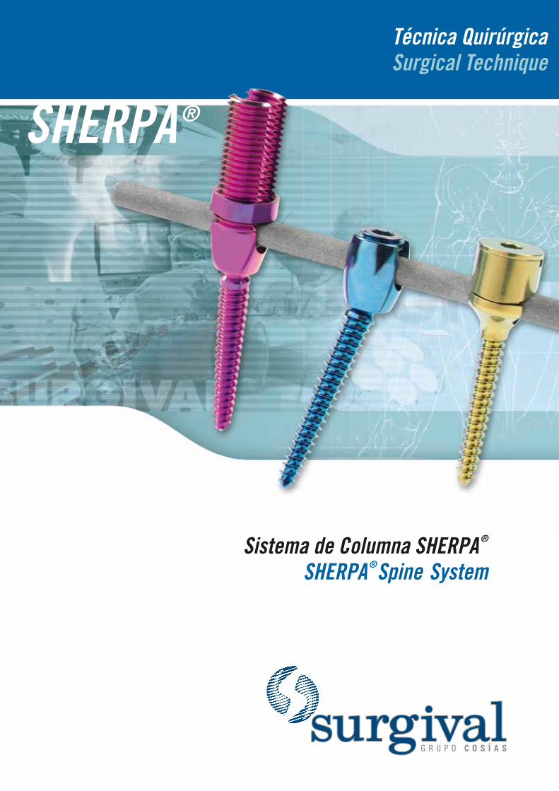
Sistema de Columna SHERPA ®
SHERPA ®Spine System

ÍndiceTable of contents
TÉCNICA QUIRÚRGICA / SURGICAL TECHNIQUE 2
1. Preparación del pedículo / Pedicle preparation 3
2. Inserción del tornillo / Screw insertion 6
3. Preparación y colocación de la barra / Rod preparation and placement 8
4. Cierre del sistema / System locking 10
5. Apriete final del sistema / Final system tightening 13
IMPLANTES E INSTRUMENTAL / IMPLANTS AND INSTRUMENTS 14
Técnica Quirúrgica Surgical Technique
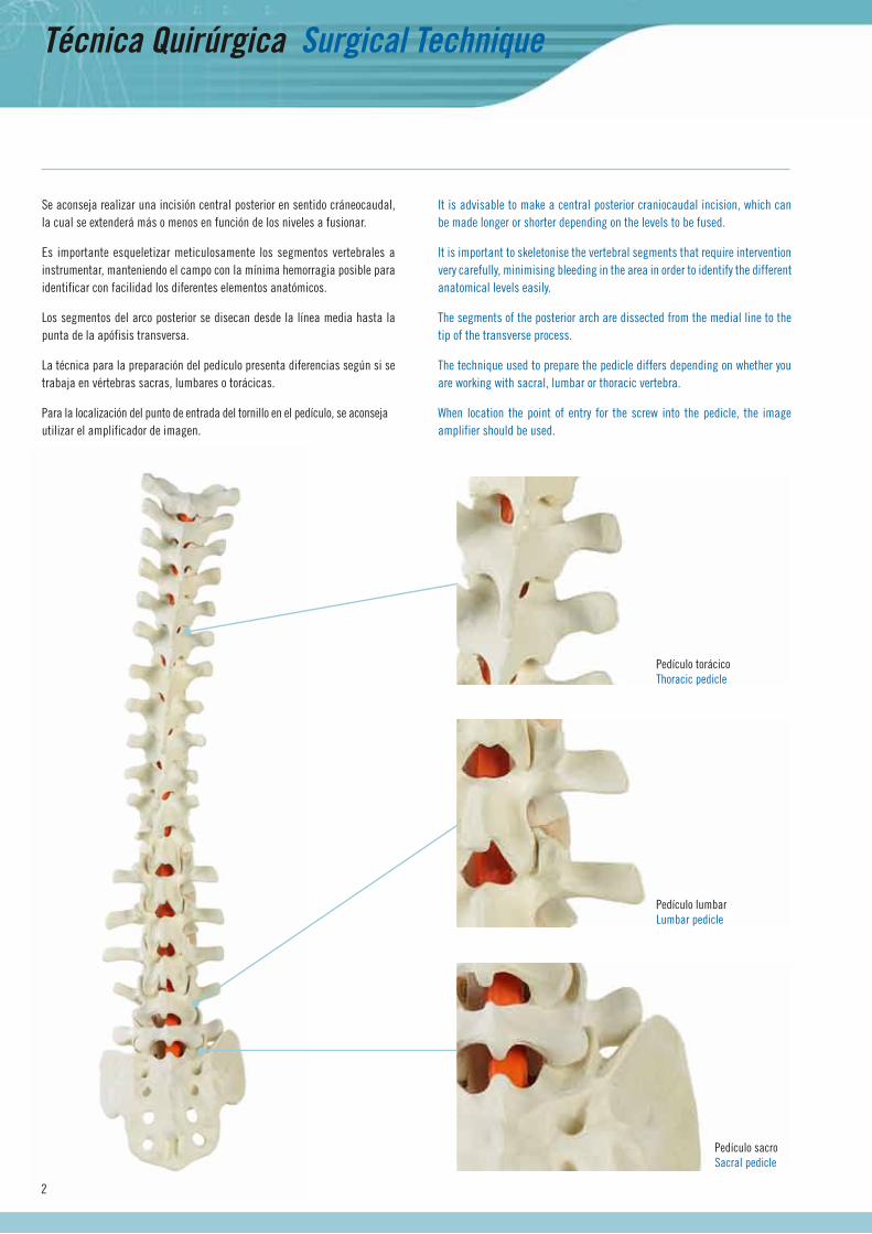
Se aconseja realizar una incisión central posterior en sentido cráneocaudal, la cual se extenderá más o menos en función de los niveles a fusionar.
Es importante esqueletizar meticulosamente los segmentos vertebrales a instrumentar, manteniendo el campo con la mínima hemorragia posible para identificar con facilidad los diferentes elementos anatómicos.
Los segmentos del arco posterior se disecan desde la línea media hasta la punta de la apófisis transversa.
La técnica para la preparación del pedículo presenta diferencias según si se trabaja en vértebras sacras, lumbares o torácicas.
Para la localización del punto de entrada del tornillo en el pedículo, se aconseja utilizar el amplificador de imagen.
It is advisable to make a central posterior craniocaudal incision, which can be made longer or shorter depending on the levels to be fused.
It is important to skeletonise the vertebral segments that require intervention very carefully, minimising bleeding in the area in order to identify the different anatomical levels easily.
The segments of the posterior arch are dissected from the medial line to the tip of the transverse process.
The technique used to prepare the pedicle differs depending on whether you are working with sacral, lumbar or thoracic vertebra.
When location the point of entry for the screw into the pedicle, the image amplifier should be used.
2
Pedículo torácicoThoracic pedicle
Pedículo lumbarLumbar pedicle
Pedículo sacroSacral pedicle
Punzón iniciadorStarter awl
Localizador pedicularPedicle finder
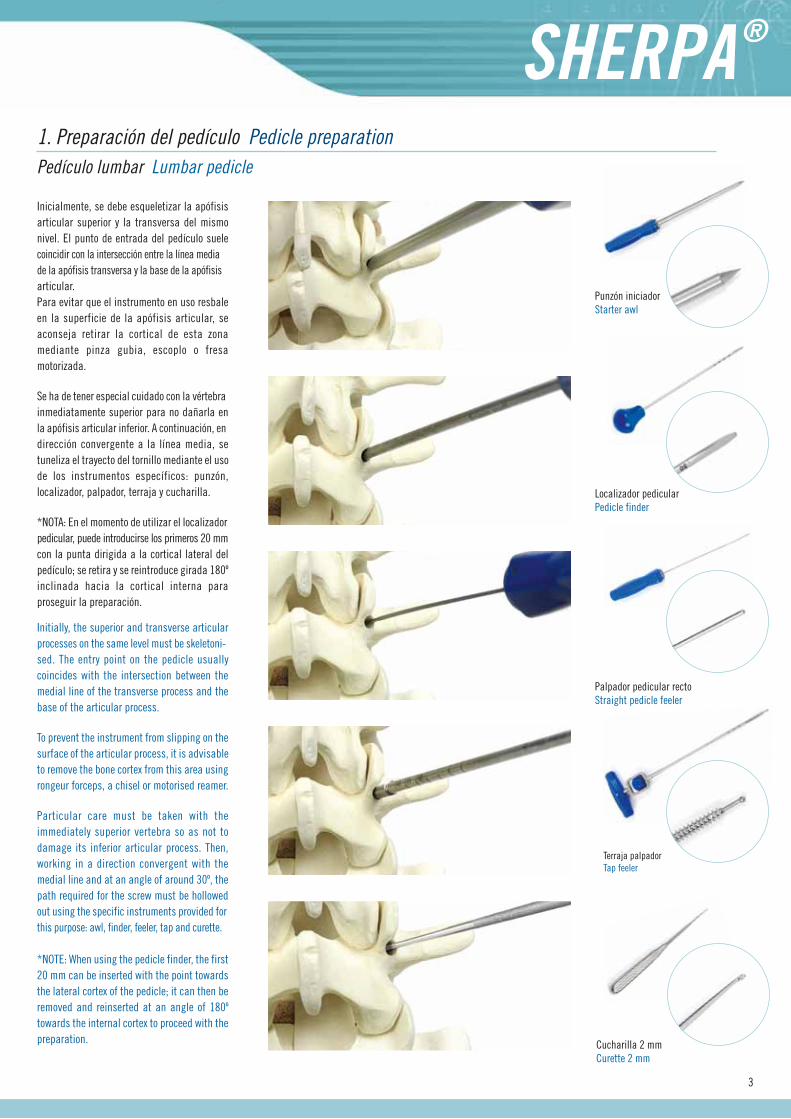
Inicialmente, se debe esqueletizar la apófisis articular superior y la transversa del mismo nivel. El punto de entrada del pedículo suelecoincidir con la intersección entre la línea media de la apófisis transversa y la base de la apófisis articular. Para evitar que el instrumento en uso resbale en la superficie de la apófisis articular, se aconseja retirar la cortical de esta zona mediante pinza gubia, escoplo o fresa motorizada.
Se ha de tener especial cuidado con la vértebra inmediatamente superior para no dañarla en la apófisis articular inferior. A continuación, endirección convergente a la línea media, se tuneliza el trayecto del tornillo mediante el uso de los instrumentos específicos: punzón, localizador, palpador, terraja y cucharilla.
*NOTA: En el momento de utilizar el localizador pedicular, puede introducirse los primeros 20 mm con la punta dirigida a la cortical lateral del pedículo; se retira y se reintroduce girada 180º inclinada hacia la cortical interna para proseguir la preparación.
1. Preparación del pedículo Pedicle preparation Pedículo lumbar Lumbar pedicle
Initially, the superior and transverse articular processes on the same level must be skeletoni-sed. The entry point on the pedicle usually coincides with the intersection between the medial line of the transverse process and the base of the articular process.
To prevent the instrument from slipping on the surface of the articular process, it is advisable to remove the bone cortex from this area using rongeur forceps, a chisel or motorised reamer.
Particular care must be taken with the immediately superior vertebra so as not to damage its inferior articular process. Then, working in a direction convergent with the medial line and at an angle of around 30º, the path required for the screw must be hollowed out using the specific instruments provided for this purpose: awl, finder, feeler, tap and curette.
*NOTE: When using the pedicle finder, the first 20 mm can be inserted with the point towards the lateral cortex of the pedicle; it can then be removed and reinserted at an angle of 180º towards the internal cortex to proceed with the preparation.
Palpador pedicular rectoStraight pedicle feeler
Terraja palpadorTap feeler
3
Cucharilla 2 mmCurette 2 mm
Técnica Quirúrgica Surgical Technique
4
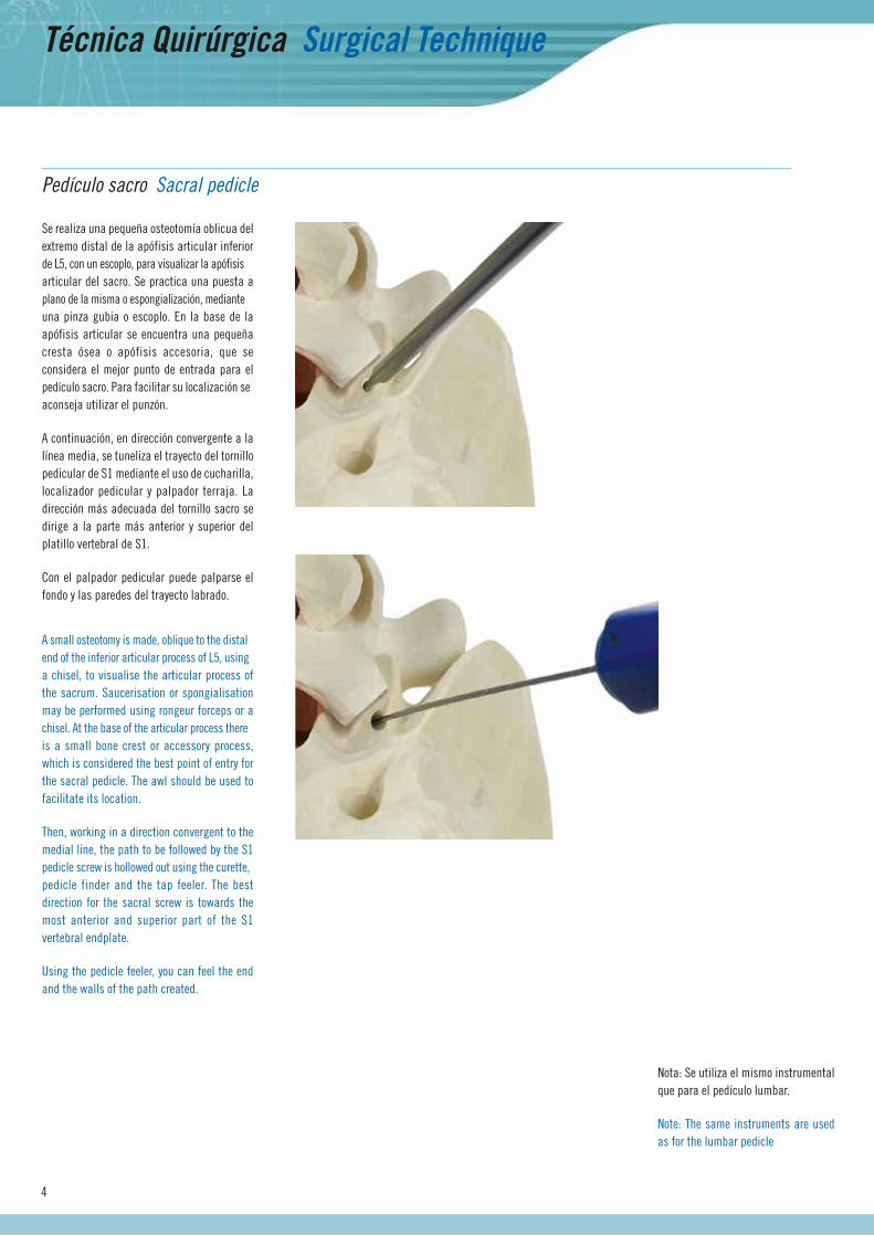
Nota: Se utiliza el mismo instrumental que para el pedículo lumbar.
Note: The same instruments are used as for the lumbar pedicle
Se realiza una pequeña osteotomía oblicua del extremo distal de la apófisis articular inferior de L5, con un escoplo, para visualizar la apófisis articular del sacro. Se practica una puesta a plano de la misma o espongialización, mediante una pinza gubia o escoplo. En la base de la apófisis articular se encuentra una pequeña cresta ósea o apófisis accesoria, que se considera el mejor punto de entrada para el pedículo sacro. Para facilitar su localización se aconseja utilizar el punzón.
A continuación, en dirección convergente a la línea media, se tuneliza el trayecto del tornillo pedicular de S1 mediante el uso de cucharilla, localizador pedicular y palpador terraja. La dirección más adecuada del tornillo sacro se dirige a la parte más anterior y superior del platillo vertebral de S1.
Con el palpador pedicular puede palparse el fondo y las paredes del trayecto labrado.
Pedículo sacro Sacral pedicle
A small osteotomy is made, oblique to the distal end of the inferior articular process of L5, using a chisel, to visualise the articular process of the sacrum. Saucerisation or spongialisation may be performed using rongeur forceps or a chisel. At the base of the articular process there is a small bone crest or accessory process, which is considered the best point of entry for the sacral pedicle. The awl should be used to facilitate its location.
Then, working in a direction convergent to the medial line, the path to be followed by the S1 pedicle screw is hollowed out using the curette, pedicle finder and the tap feeler. The best direction for the sacral screw is towards the most anterior and superior part of the S1 vertebral endplate.
Using the pedicle feeler, you can feel the end and the walls of the path created.
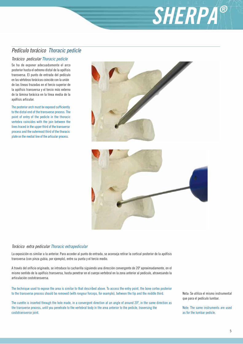
Se ha de exponer adecuadamente el arco posterior hasta el extremo distal de la apófisis transversa. El punto de entrada del pedículo en las vértebras torácicas coincide con la unión de las líneas trazadas en el tercio superior de la apófisis transversa y el tercio más externo de la lámina torácica en la línea media de la apófisis articular.
Torácico pedicular Thoracic pedicle
Pedículo torácico Thoracic pedicle
The posterior arch must be exposed sufficiently to the distal end of the transverse process. The point of entry of the pedicle in the thoracic vertebra coincides with the join between the lines traced in the upper third of the transverse process and the outermost third of the thoracic plate on the medial line of the articular process.
La exposición es similar a la anterior. Para acceder al punto de entrada, se aconseja retirar la cortical posterior de la apófisis transversa (con pinza gubia, por ejemplo), entre su punta y el tercio medio.
A través del orificio originado, se introduce la cucharilla siguiendo una dirección convergente de 20º aproximadamente, en el mismo sentido de la apófisis transversa, hasta penetrar en el cuerpo vertebral en la zona anterior al pedículo, atravesando la articulación costotransversa.
Torácico extra pedicular Thoracic extrapedicular
The technique used to expose the area is similar to that described above. To access the entry point, the bone cortex posterior to the transverse process should be removed (with rongeur forceps, for example), between the tip and the middle third.
The curette is inserted through the hole made, in a convergent direction at an angle of around 20º, in the same direction as the transverse process, until you penetrate to the vertebral body in the area anterior to the pedicle, traversing the costotransverse joint.
5
Nota: Se utiliza el mismo instrumental que para el pedículo lumbar.
Note: The same instruments are used as for the lumbar pedicle.
Técnica Quirúrgica Surgical Technique
Inserción tornillo monoaxial Monoaxial screw insertion
2. Inserción del tornillo Screw insertion
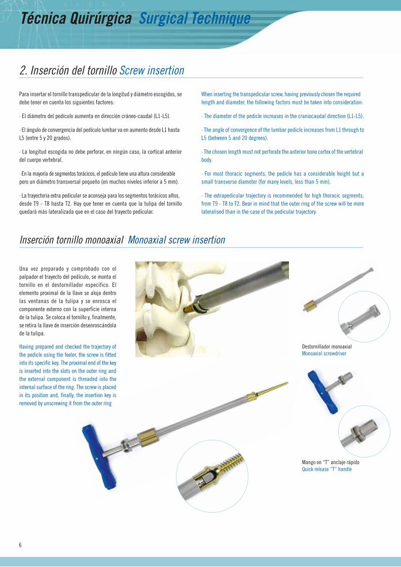
Para insertar el tornillo transpedicular de la longitud y diámetro escogidos, se debe tener en cuenta los siguientes factores:
· El diámetro del pedículo aumenta en dirección cráneo-caudal (L1-L5).
· El ángulo de convergencia del pedículo lumbar va en aumento desde L1 hasta L5 (entre 5 y 20 grados).
· La longitud escogida no debe perforar, en ningún caso, la cortical anterior del cuerpo vertebral.
· En la mayoría de segmentos torácicos, el pedículo tiene una altura considerable pero un diámetro transversal pequeño (en muchos niveles inferior a 5 mm).
· La trayectoria extra pedicular se aconseja para los segmentos torácicos altos, desde T9 - T8 hasta T2. Hay que tener en cuenta que la tulipa del tornillo quedará más lateralizada que en el caso del trayecto pedicular.
When inserting the transpedicular screw, having previously chosen the required length and diameter, the following factors must be taken into consideration:
· The diameter of the pedicle increases in the craniocaudal direction (L1-L5).
· The angle of convergence of the lumbar pedicle increases from L1 through to L5 (between 5 and 20 degrees).
· The chosen length must not perforate the anterior bone cortex of the vertebral body.
· For most thoracic segments, the pedicle has a considerable height but a small transverse diameter (for many levels, less than 5 mm).
· The extrapedicular trajectory is recommended for high thoracic segments, from T9 - T8 to T2. Bear in mind that the outer ring of the screw will be more lateralised than in the case of the pedicular trajectory.
Destornillador monoaxialMonoaxial screwdriver
Mango en “T” anclaje rápidoQuick release “T” handle
6
Una vez preparado y comprobado con el palpador el trayecto del pedículo, se monta el tornillo en el destornillador específico. El elemento proximal de la llave se aloja dentro las ventanas de la tulipa y se enrosca el componente externo con la superficie interna de la tulipa. Se coloca el tornillo y, finalmente, se retira la llave de inserción desenroscándola de la tulipa.
Having prepared and checked the trajectory of the pedicle using the feeler, the screw is fitted into its specific key. The proximal end of the key is inserted into the slots on the outer ring and the external component is threaded into the internal surface of the ring. The screw is placed in its position and, finally, the insertion key is removed by unscrewing it from the outer ring
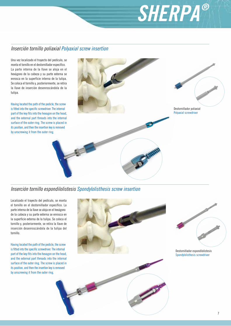
Una vez localizado el trayecto del pedículo, se monta el tornillo en el destornillador específico. La parte interna de la llave se aloja en el hexágono de la cabeza y su parte externa se enrosca en la superficie interna de la tulipa.Se coloca el tornillo y, posteriormente, se retira la llave de inserción desenroscándola de la tulipa.
Inserción tornillo poliaxial Polyaxial screw insertion
Having located the path of the pedicle, the screw is fitted into the specific screwdriver. The internal part of the key fits into the hexagon on the head, and the external part threads into the internal surface of the outer ring. The screw is placed in its position, and then the insertion key is removed by unscrewing it from the outer ring.
Destornillador poliaxialPolyaxial screwdriver
7
Localizado el trayecto del pedículo, se monta el tornillo en el destornillador específico. La parte interna de la llave se aloja en el hexágono de la cabeza y su parte externa se enrosca en la superficie externa de la tulipa. Se coloca el tornillo y, posteriormente, se retira la llave de inserción desenroscándola de la tulipa del tornillo.
Inserción tornillo espondilolistesis Spondylolisthesis screw insertion
Having located the path of the pedicle, the screw is fitted into the specific screwdriver. The internal part of the key fits into the hexagon on the head, and the external part threads into the internal surface of the outer ring. The screw is placed in its position, and then the insertion key is removed by unscrewing it from the outer ring.
Destornillador espondilolistesisSpondylolisthesis screwdriver

Técnica Quirúrgica Surgical Technique
Con la ayuda de la pinza porta barras, se presenta la barra sobre los tornillos para seleccionar la longitud adecuada de la misma. Al mismo tiempo, se obtiene una imagen de la silueta necesaria para iniciar el moldeo de ésta. Dicha maniobra se realiza con el doblador francés, en la posición 6 equivalente a la barra de Ø 6 mm, y la pinza porta barras.
3. Preparación y colocación de la barra Rod preparation and placement
Using the rod holders, offer the rod up to the screws to select the right length. At the same time, you will get an image of the outline required to start moulding the rod. The rod should be moulded using the bending pliers, in position 6, equivalent to the Ø 6 mm rod, and the rod holders.
Doblador de barrasRod bending pliers
Pinzas portabarrasRod holders
8
Calzador de tulipasOuter ring lever
9
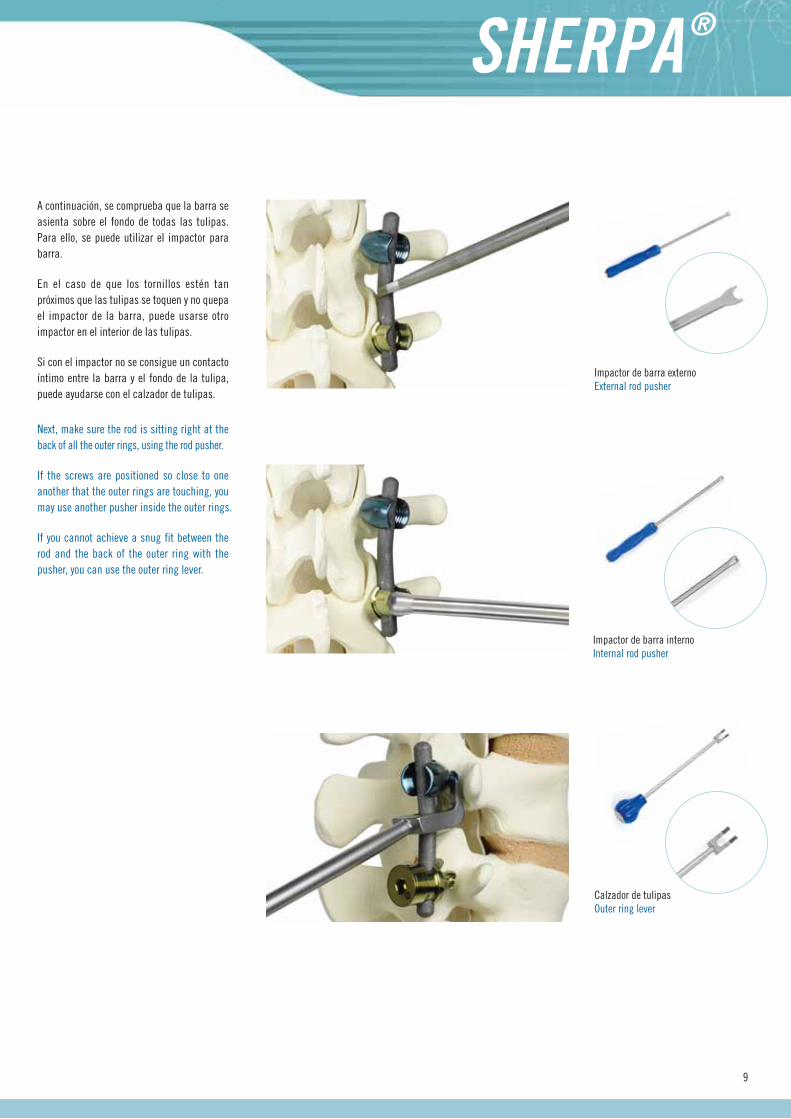
A continuación, se comprueba que la barra se asienta sobre el fondo de todas las tulipas. Para ello, se puede utilizar el impactor para barra.
En el caso de que los tornillos estén tan próximos que las tulipas se toquen y no quepa el impactor de la barra, puede usarse otro impactor en el interior de las tulipas.
Si con el impactor no se consigue un contacto íntimo entre la barra y el fondo de la tulipa, puede ayudarse con el calzador de tulipas.
Impactor de barra internoInternal rod pusher
Impactor de barra externoExternal rod pusher
Next, make sure the rod is sitting right at the back of all the outer rings, using the rod pusher.
If the screws are positioned so close to one another that the outer rings are touching, you may use another pusher inside the outer rings.
If you cannot achieve a snug fit between the rod and the back of the outer ring with the pusher, you can use the outer ring lever.
Técnica Quirúrgica Surgical Technique
4.Cierre del sistema System locking
Una vez introducida la barra, se cierra el sistema mediante los diferentes elementos de apriete, según se trate de un tornillo monoaxial, poliaxial o de espondilolistesis.
Having inserted the rod, lock the system in place using the various tightening elements, depending on whether you are locking a monoaxial, polyaxial or spondylolisthesis screw.
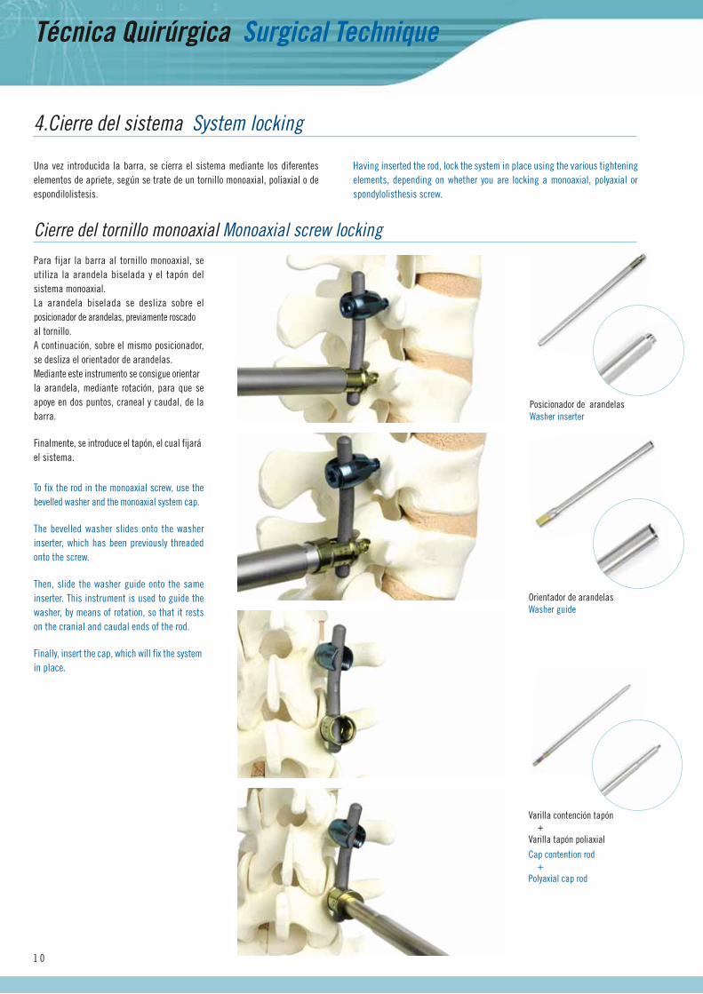
Para fijar la barra al tornillo monoaxial, se utiliza la arandela biselada y el tapón del sistema monoaxial.La arandela biselada se desliza sobre el posicionador de arandelas, previamente roscado al tornillo.A continuación, sobre el mismo posicionador, se desliza el orientador de arandelas.Mediante este instrumento se consigue orientar la arandela, mediante rotación, para que se apoye en dos puntos, craneal y caudal, de la barra.
Finalmente, se introduce el tapón, el cual fijará el sistema.
Cierre del tornillo monoaxial Monoaxial screw locking
Posicionador de arandelasWasher inserter
Orientador de arandelasWasher guide
1 0
To fix the rod in the monoaxial screw, use the bevelled washer and the monoaxial system cap.
The bevelled washer slides onto the washer inserter, which has been previously threaded onto the screw.
Then, slide the washer guide onto the same inserter. This instrument is used to guide the washer, by means of rotation, so that it rests on the cranial and caudal ends of the rod.
Finally, insert the cap, which will fix the system in place.
Varilla contención tapón +Varilla tapón poliaxial
Cap contention rod + Polyaxial cap rod
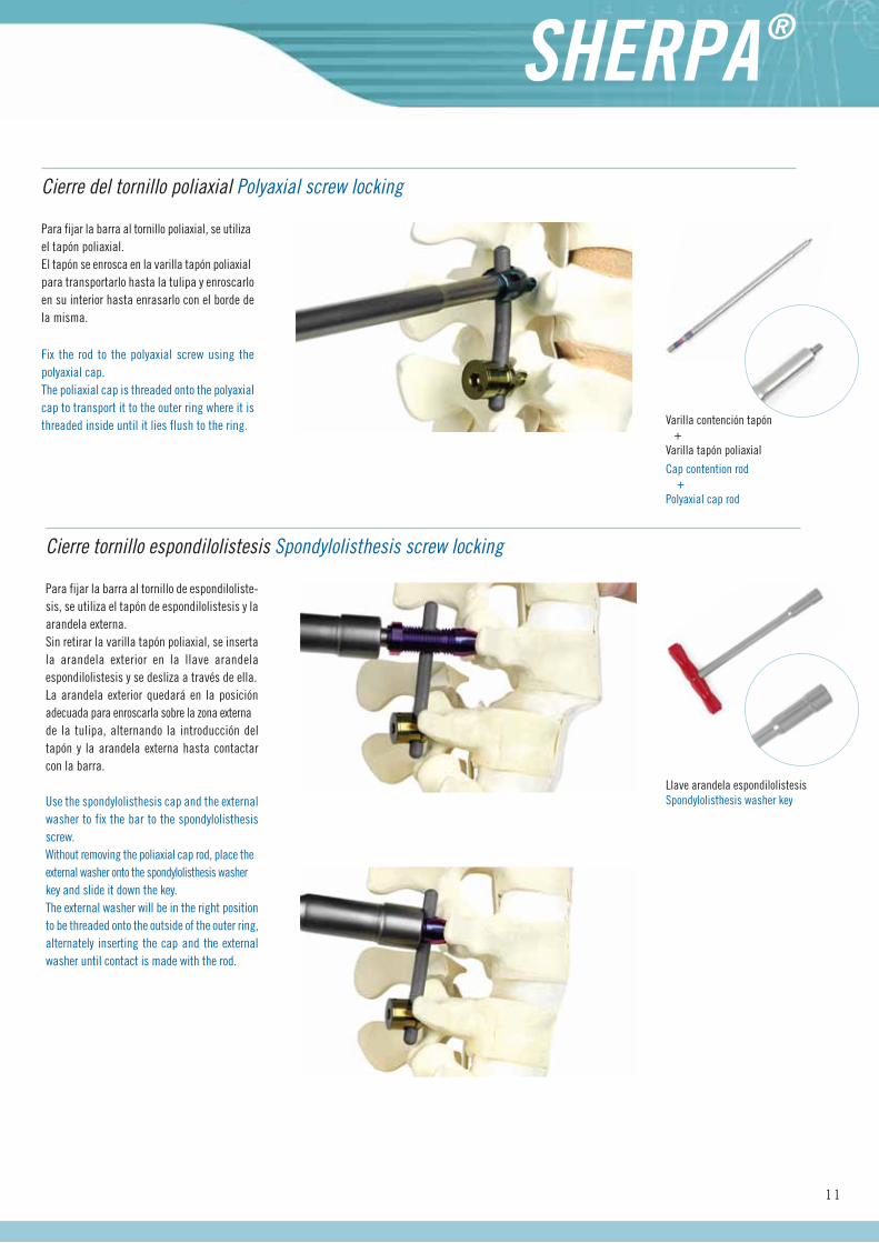
Para fijar la barra al tornillo poliaxial, se utiliza el tapón poliaxial. El tapón se enrosca en la varilla tapón poliaxial para transportarlo hasta la tulipa y enroscarlo en su interior hasta enrasarlo con el borde de la misma.
Fix the rod to the polyaxial screw using the polyaxial cap.The poliaxial cap is threaded onto the polyaxial cap to transport it to the outer ring where it is threaded inside until it lies flush to the ring.
Cierre del tornillo poliaxial Polyaxial screw locking
1 1
Para fijar la barra al tornillo de espondiloliste-sis, se utiliza el tapón de espondilolistesis y la arandela externa. Sin retirar la varilla tapón poliaxial, se inserta la arandela exterior en la llave arandela espondilolistesis y se desliza a través de ella.La arandela exterior quedará en la posición adecuada para enroscarla sobre la zona externa de la tulipa, alternando la introducción del tapón y la arandela externa hasta contactar con la barra.
Varilla contención tapón +Varilla tapón poliaxial
Cap contention rod +Polyaxial cap rod
Cierre tornillo espondilolistesis Spondylolisthesis screw locking
Use the spondylolisthesis cap and the external washer to fix the bar to the spondylolisthesis screw.Without removing the poliaxial cap rod, place the external washer onto the spondylolisthesis washer key and slide it down the key.The external washer will be in the right position to be threaded onto the outside of the outer ring, alternately inserting the cap and the external washer until contact is made with the rod.
Llave arandela espondilolistesisSpondylolisthesis washer key
Técnica Quirúrgica Surgical Technique
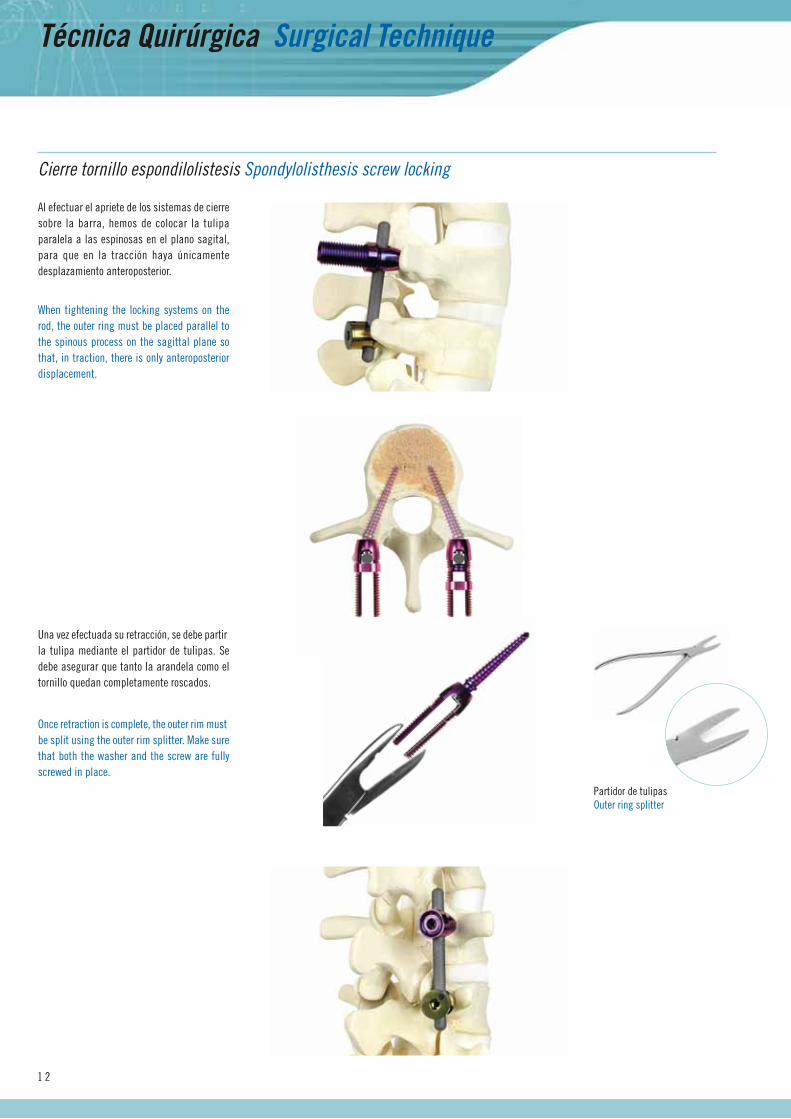
Al efectuar el apriete de los sistemas de cierre sobre la barra, hemos de colocar la tulipa paralela a las espinosas en el plano sagital, para que en la tracción haya únicamente desplazamiento anteroposterior.
Cierre tornillo espondilolistesis Spondylolisthesis screw locking
1 2
When tightening the locking systems on the rod, the outer ring must be placed parallel to the spinous process on the sagittal plane so that, in traction, there is only anteroposterior displacement.
Partidor de tulipasOuter ring splitter
Una vez efectuada su retracción, se debe partir la tulipa mediante el partidor de tulipas. Se debe asegurar que tanto la arandela como el tornillo quedan completamente roscados.
Once retraction is complete, the outer rim must be split using the outer rim splitter. Make sure that both the washer and the screw are fully screwed in place.
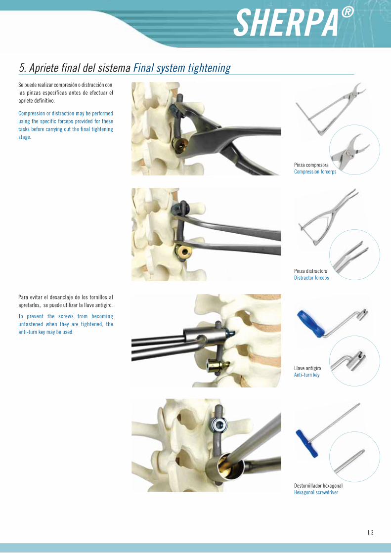
Se puede realizar compresión o distracción con las pinzas específicas antes de efectuar el apriete definitivo.
Compression or distraction may be performed using the specific forceps provided for these tasks before carrying out the final tightening stage.
5. Apriete final del sistema Final system tightening
Pinza compresoraCompression forcerps
Pinza distractoraDistractor forceps
Llave antigiroAnti-turn key
Destornillador hexagonalHexagonal screwdriver
1 3
Para evitar el desanclaje de los tornillos al apretarlos, se puede utilizar la llave antigiro.
To prevent the screws from becoming unfastened when they are tightened, the anti-turn key may be used.
ImplantesImplants
1 4
Ref. C6800740
Ref. C6800750
Ref. C6800760
Ref. C6800770
Ref. C6800780
Ref. C6800790
40 mm
50 mm
60 mm
70 mm
80 mm
90 mm
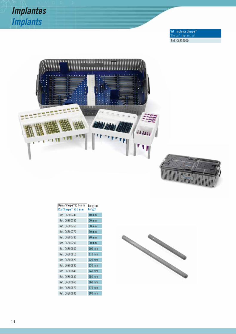
Barra Sherpa® Ø 6 mmRod Sherpa® Ø 6 mm
LongitudLength
Ref. C6800800
Ref. C6800810
Ref. C6800820
Ref. C6800830
Ref. C6800850
Ref. C6800860
100 mm
110 mm
120 mm
130 mm
150 mm
160 mm
Ref. C6800870 170 mm
Ref. C6800840 140 mm
Ref. C6800880 180 mm
Ref. C6836000
Set implante Sherpa®
Sherpa® implant set
1 5
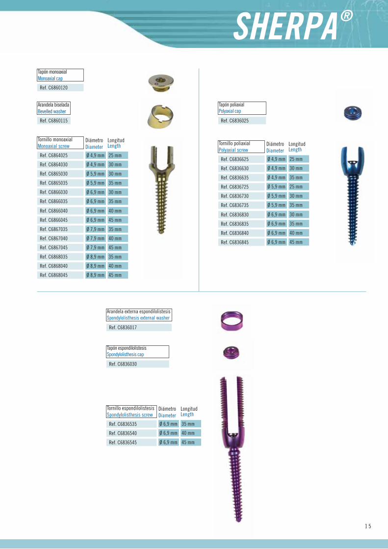
Ref. C6860120
Tapón monoaxialMonoaxial cap
Ref. C6860115
Arandela biseladaBevelled washer
Ref. C6836030
Tapón espondilolistesisSpondylolisthesis cap
Ref. C6836017
Arandela externa espondilolistesisSpondylolisthesis external washer
Ref. C6836535
Ref. C6836540
Ref. C6836545
Tornillo espondilolistesisSpondylolisthesis screw
Ø 6,9 mm
Ø 6,9 mm
Ø 6,9 mm
LongitudLength
DiámetroDiameter
35 mm
40 mm
45 mm
Ref. C6864025
Ref. C6864030
Ref. C6865030
Ref. C6865035
Ref. C6866030
Ref. C6866035
Tornillo monoaxialMonoaxial screw
Ref. C6866040
Ref. C6866045
Ref. C6867035
Ref. C6867040
Ref. C6868035
Ref. C6868040
Ref. C6868045
Ref. C6867045
Ø 4,9 mm
Ø 4,9 mm
Ø 5,9 mm
Ø 5,9 mm
Ø 6,9 mm
Ø 6,9 mm
LongitudLength
Ø 6,9 mm
Ø 6,9 mm
Ø 7,9 mm
Ø 7,9 mm
Ø 8,9 mm
Ø 8,9 mm
Ø 8,9 mm
Ø 7,9 mm
DiámetroDiameter
25 mm
30 mm
30 mm
35 mm
30 mm
35 mm
40 mm
45 mm
35 mm
40 mm
35 mm
40 mm
45 mm
45 mm
Ref. C6836625
Ref. C6836630
Ref. C6836635
Ref. C6836725
Ref. C6836730
Ref. C6836735
Tornillo poliaxialPolyaxial screw
Ref. C6836830
Ref. C6836835
Ref. C6836840
Ref. C6836845
Ref. C6836025
Tapón poliaxialPolyaxial cap
Ø 4,9 mm
Ø 4,9 mm
Ø 4,9 mm
Ø 5,9 mm
Ø 5,9 mm
Ø 5,9 mm
LongitudLength
Ø 6,9 mm
Ø 6,9 mm
Ø 6,9 mm
Ø 6,9 mm
DiámetroDiameter
25 mm
30 mm
35 mm
25 mm
30 mm
35 mm
30 mm
35 mm
40 mm
45 mm
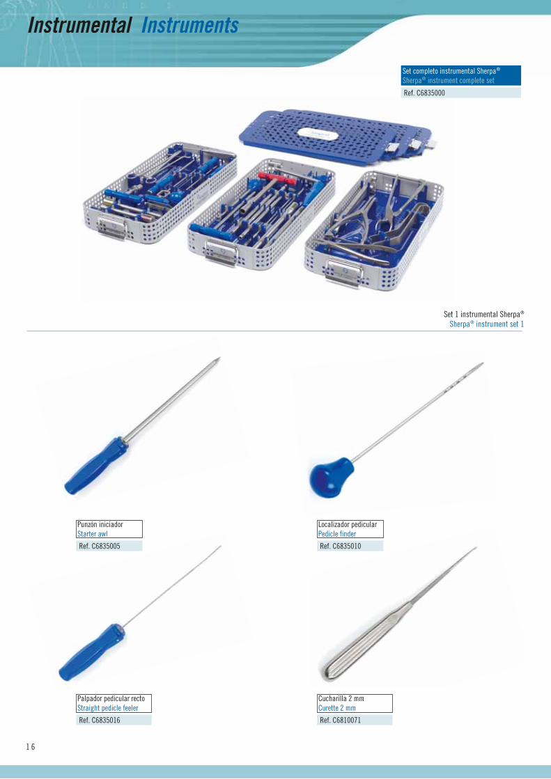
Instrumental Instruments
1 6
Ref. C6835005
Punzón iniciador Starter awl
Ref. C6835010
Localizador pedicular Pedicle finder
Ref. C6835016
Palpador pedicular rectoStraight pedicle feeler
Ref. C6810071
Cucharilla 2 mmCurette 2 mm
Ref. C6835000
Set completo instrumental Sherpa®
Sherpa® instrument complete set
Set 1 instrumental Sherpa®
Sherpa® instrument set 1
1 7
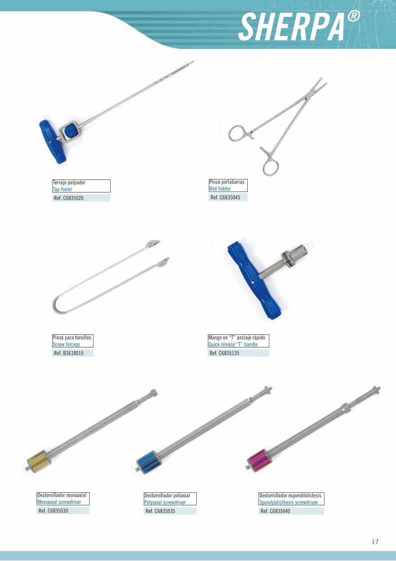
Ref. C6835020
Terraja palpadorTap feeler
Ref. C6835135
Mango en “T” anclaje rápidoQuick release “T” handle
Ref. B3618015
Pinza para tornillosScrew forceps
Ref. C6835030
Destornillador monoaxialMonoaxial screwdriver
Ref. C6835035
Destornillador poliaxialPolyaxial screwdriver
Ref. C6835040
Destornillador espondilolistesisSpondylolisthesis screwdriver
Ref. C6835045
Pinza portabarrasRod holder
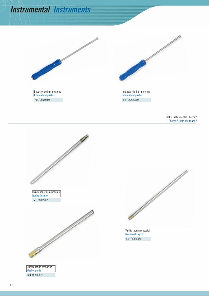
Instrumental Instruments
1 8
Ref. C6835055
Impactor de barra externoExternal rod pusher
Ref. C6835060
Impactor de barra internoInternal rod pusher
Ref. C6835065
Posicionador de arandelasWasher inserter
Ref. C6835070
Orientador de arandelasWasher guide
Ref. C6835085
Varilla tapón monoaxialMonoaxial cap rod
Set 2 instrumental Sherpa®
Sherpa® instrument set 2
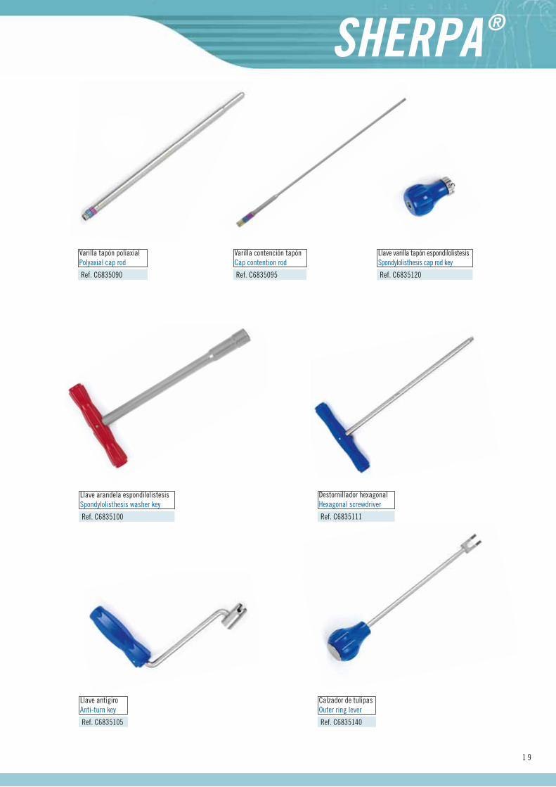
1 9
Ref. C6835090
Varilla tapón poliaxialPolyaxial cap rod
Ref. C6835095
Varilla contención tapónCap contention rod
Ref. C6835100
Llave arandela espondilolistesisSpondylolisthesis washer key
Ref. C6835120
Llave varilla tapón espondilolistesisSpondylolisthesis cap rod key
Ref. C6835111
Destornillador hexagonalHexagonal screwdriver
Ref. C6835105
Llave antigiroAnti-turn key
Ref. C6835140
Calzador de tulipasOuter ring lever
2 0
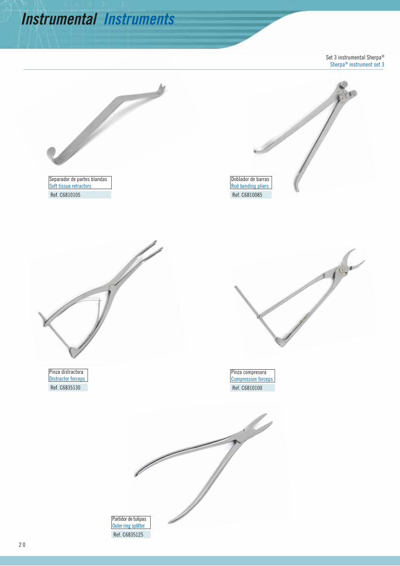
Ref. C6810105
Separador de partes blandasSoft tissue retractors
Ref. C6835130
Pinza distractoraDistractor forceps
Ref. C6835125
Partidor de tulipasOuter ring splitter
Ref. C6810100
Pinza compresoraCompression forceps
Ref. C6810085
Doblador de barrasRod bending pliers
Instrumental Instruments
Set 3 instrumental Sherpa®
Sherpa® instrument set 3

Tecnología Europea de VanguardiaAdvanced European Technology
Distribuido por: Distributed by:
1
3
4 7
2
5
6
1
2
3
1
2
4
6
53
K.H.A
Cotilo K.H.A..K.H.A. Cup
Instrumental Instruments
Implantes Implants
CotilosCups
Ref. F0005545 45 mm longitud length
Ref. F0005540 40 mm longitud length
Ref. F0005535 35 mm longitud length
Ref. F0005530 30 mm longitud length
Ref. F0005525 25 mm longitud length
Ref. F0005520 20 mm longitud length
Ref. F0005762E
Ref. F0005760E
Ref. F0005758E
Ref. F0005756E
Ref. F0005754E
Ref. F0005752E
Ref. F0005750E
Ref. F0005748E
Ref. F0005746E
Ø 62 mm / Ø 28 mm
Ø 60 mm / Ø 28 mm
Ø 58 mm / Ø 28 mm
Ø 56 mm / Ø 28 mm
Ø 54 mm / Ø 28 mm
Ø 52 mm / Ø 28 mm
Ø 50 mm / Ø 28 mm
Ø 48 mm / Ø 26 mm
Ø 46 mm / Ø 26 mm
Ref. F0005662E Ø 62 mm HA
Ref. F0005660E Ø 60 mm HA
Ref. F0005658E Ø 58 mm HA
Ref. F0005656E Ø 56 mm HA
Ref. F0005654E Ø 54 mm HA
Ref. F0005652E Ø 52 mm HA
Ref. F0005650E Ø 50 mm HA
Ref. F0005648E Ø 48 mm HA
Ref. F0005646E Ø 46 mm HA
Insertos cotiloCup inserts
TornillosScrews
Set completo instrumental K.H.A.K.H.A. instrumentation complete set
Ref.
F0005601
Set instrumental Cotilo K.H.A.K.H.A.Cup instrumentation set
Ref. F0005605
Bandeja superiorUpper tray
Ref. B3610000 Recto Straight
Ref. B3611350 Cardan Cardan
Destornilladores hexagonalesHexagonal screwdrivers
1
Pinza porta-tornillosScrew holding forceps Ref. F00059502
Guía de brocaDrill guide Ref. F00059353
Árbol flexible para brocasDrills flexible shafts Ref. F00059304
Ref. F0005931 Ø 3,2 x 35 mm
Ref. F0005932 Ø 3,2 x 56 mm
BrocasDrill bits
5
Medidor de profundidadDepth gauge Ref. F00059606
Ref. A1701075
Ref. A1701056 Ø 56 mm
Ref. A1701058 Ø 58 mm
Ref. A1701060 Ø 60 mm
Ref. A1701062 Ø 62 mm
Ref. A1701054 Ø 54 mm
Set fresas acetabularesAcetabular reamer set Ref. A1701000
Ref. A1701044 Ø 44 mm
Ref. A1701046 Ø 46 mm
Ref. A1701048 Ø 48 mm
Ref. A1701050 Ø 50 mm
Ref. A1701052 Ø 52 mm
Fresa acetabularAcetabular reamer
1
Mango porta fresa acetabular universalHandle for universal acetabular reamer
3
Acople universalUniversal Join Ref. A17003802
Ref. F0005846 Ø 46 mm
Ref. F0005848 Ø 48 mm
Ref. F0005850 Ø 50 mm
Ref. F0005852 Ø 52 mm
Ref. F0005854 Ø 54 mm
Ref. F0005856 Ø 56 mm
Ref. F0005858 Ø 58 mm
Ref. F0005860 Ø 60 mm
Ref. F0005862 Ø 62 mm
Cotilos de pruebaTrial acetabular cups
Ref. F0005831 46/48 Ø 26 mm
Ref. F0005832 50/52 Ø 28 mm
Posicionador insertoPositioner for inserts
Impactor final para cotiloCup final impactor Ref. A2400870
Bandeja inferiorLower tray
Impactor orientador cotiloCup guide impactor Ref. F0005830
Extractor para inser
2 unidades 2 units
toInserts extractor Ref. F0005900
14
6
7Ref. A2400834 Ø 26 mm
Ref. A2400835 Ø 28 mmImpactor definitivo inserto-cotiloDefinitive cup-insert impactor
2
5
Mango para cotiloCup´s handle Ref. F00058353
2 unidades 2 units
2 unidades 2 units
SURGIVAL COMERCIAL C/Ignacio Iglesias, 70
08950 Esplugues de Llobregrat · Barcelona · EspañaTel: (+34) 93 480 92 22 · Fax: (+34) 93 480 92 23
e-mail: [email protected]
FÁBRICA / DEPARTAMENTO INTERNACIONALParque Tecnológico
C/ Leonardo Da Vinci, 12-14 · 46980 Paterna · Valencia · EspañaTel: (+34) 96 131 80 50 · Fax: (+34) 96 131 80 95
e-mail: [email protected]
www.surgival.com 0086 ICOSHETQ01
/ 07-2
015 ©
Rev
. 1
El m
arca
do C
E es
vál
ido
únic
amen
te s
i tam
bién
est
á im
pres
o en
la e
tique
ta d
el p
rodu
cto.