Embed Size (px)
Citation preview
JLR No.: 24566-002 Revision: 0
January 11, 2019
Prepared for: MINTO COMMUNITIES INC. 200-180 Kent Street Ottawa, ON K1P 0B6
Prepared by: J.L. RICHARDS & ASSOCIATES LIMITED 1565 Carling Avenue Ottawa, ON K1Z 8R1
Site Servicing Brief
Morgan’s Creek – Stage 2 335 Sandhill Road Ottawa, Ontario
Value through service and commitment

Site Servicing Brief 335 Sandhill Road
J.L. Richards & Associates Limited January 11, 2019 JLR No.: 24566-002 -i- Revision: 0
Table of Contents
1.0 Introduction ........................................................................................................................ 1 1.1 Background ............................................................................................................ 1 1.2 Site Description ...................................................................................................... 1 1.3 Existing Infrastructure ............................................................................................ 2 1.4 Background Documents ........................................................................................ 2 1.5 Consultation and Permits ....................................................................................... 2
2.0 Geotechnical ..................................................................................................................... 3 3.0 Water Servicing ................................................................................................................. 4
3.1 Design Criteria ....................................................................................................... 4 3.2 Domestic Water Demands ..................................................................................... 4 3.3 Proposed Water Servicing and Roughness Coefficients ....................................... 5 3.4 Watermain Sizing and Roughness Coefficients ..................................................... 6 3.5 Hydraulic Boundary Conditions ............................................................................. 7 3.6 Simulation Results ................................................................................................. 7
4.0 Wastewater Servicing ........................................................................................................ 9 4.1 Design Criteria ....................................................................................................... 9 4.2 Proposed Sanitary Sewer Servicing and Calculations ........................................... 9 4.3 Summary and Conclusions .................................................................................. 10
5.0 Storm Servicing and Stormwater Management ............................................................... 11 5.1 General ................................................................................................................ 11 5.2 Storm Criteria ....................................................................................................... 11 5.3 Proposed Storm Servicing and Calculations ....................................................... 12 5.4 Summary and Conclusions .................................................................................. 15
6.0 Summary of Servicing and Recommendations ............................................................... 16
List of Tables
Table 3-1: Water Consumption Unit Rates ................................................................................... 5 Table 3-2: Calculated Water Demands ......................................................................................... 5 Table 3-3: Watermain Roughness Coefficients ............................................................................ 5 Table 3-4: PVC Watermain Internal Diameters ............................................................................. 6 Table 3-5: FUS Fire Flow Requirements ...................................................................................... 7 Table 3-6: Hydraulic Boundary Conditions at Existing Stubs ........................................................ 7 Table 4-1: Wastewater Servicing Design Criteria ......................................................................... 9 Table 4-2: Peak Wastewater Flows ............................................................................................ 10 Table 5-1: Stormwater Servicing Design Criteria ........................................................................ 12 Table 5-2: Summary of Stormwater Management Calculations and On-Site Retention Measures .................................................................................................................................................... 14
Site Servicing Brief 335 Sandhill Road
J.L. Richards & Associates Limited January 11, 2019 JLR No.: 24566-002 -ii- Revision: 0
List of Appendices
Appendix ' A ' - Background Documents Appendix ' B ' - Watermain Appendix ' C ' - Sanitary Appendix ' D ' - Storm Appendix ' E ' - Preliminary Engineering Drawings
Site Servicing Brief 335 Sandhill Road
J.L. Richards & Associates Limited January 11, 2019 JLR No.: 24566-002 -1- Revision: 0
1.0 Introduction
1.1 Background
Minto Communities Incorporated (Minto), along with their subsidiary companies, is one of the major landowners in the Kanata North Urban Area, located in the western portion of the City of Ottawa. In 2012, J.L. Richards & Associates Limited (JLR) had been retained by Minto to proceed with detailed design of municipal infrastructure for a private development located at 760 March Road referred to as Morgan’s Creek.
The Morgan’s Creek development consisted of a 2.87 ha parcel bisected by Shirley’s Brook, within the jurisdiction of the Mississippi Valley Conservation Authority (MVCA). Given that Shirley’s Brook represents a natural barrier bisecting the parcel, the overall servicing for the property was divided into two (2) sites (for design purposes) and investigated independently based on their respective frontage. The western parcel fronting onto March Road was referred to as the March Road Site (Site 1) while the eastern parcel fronting onto Sandhill Road was referred to as the Sandhill Road Site (Site 2). A Site Servicing Brief was submitted to the City of Ottawa (City) in 2012, which described infrastructure requirements for both private sites. Subsequently, the City and other regulatory agencies granted Site Plan Approvals. The infrastructure works were tendered in 2012 and a composite utility plan (CUP) was submitted to the City in 2013. Although the Tender was awarded, construction was never initiated on either of the sites.
Minto now wishes to revise the housing product and layout for both sites (March Road and Sandhill Road) to satisfy current housing demands in the Kanata North Urban Area. It is proposed to develop Morgan’s Creek in two (2) stages; Stage 1 consists of the development fronting March Road (762 March Road) while Stage 2 consists of the development fronting Sandhill Road (335 Sandhill Road). The approval for Stage 1 will be under Site Plan Control and subsequent Plan of Condominium, while Stage 2 will require approval under Draft Plan of Subdivision and Plan of Condominium.
This Servicing Brief has been prepared solely for Morgan’s Creek Stage 2 (335 Sandhill Road) for the purpose of rezoning as well as to outline the proposed servicing strategy for the Stage 2 lands in accordance with the limitation of existing infrastructure and the City of Ottawa Servicing Study Guidelines for Development Applications (2009). This includes conceptual servicing solutions for water, wastewater and stormwater management.
1.2 Site Description
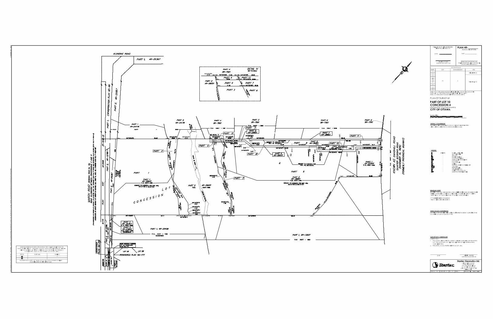
The overall Morgan’s Creek is sited on a ±2.87 ha parcel bisected by Shirley’s Brook. As a result of this constraint, a significant portion of the parcel (±0.57 ha) will not be developable as this block is floodplain land. The legal description of the subject property is Part of Lot 10, Concession 4, Geographic Township of March, City of Ottawa (refer to Appendix ‘A’ for Draft Plan of Subdivision). As noted previously, this Servicing Brief was prepared solely for Morgan’s Creek Stage 2 (335 Sandhill Road).
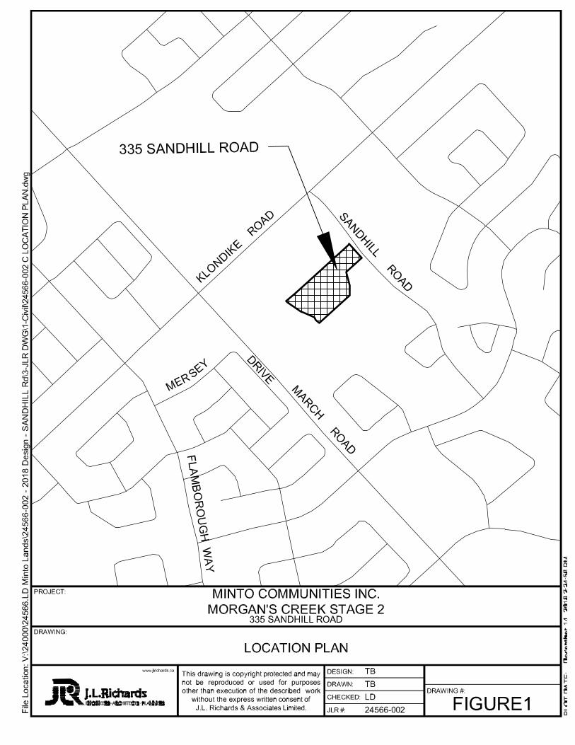
Currently, the site is undeveloped with the exception of a small gravel pad abutting Sandhill Road. Topography generally slopes westerly toward Shirley’s Brook. Stage 2 of Morgan’s Creek, which total 1.59 ha, is bounded along by Shirley’s Brook along its western perimeter, by Sandhill Road along its eastern perimeter, by an existing cemetery to the south, and by an existing residential
Site Servicing Brief 335 Sandhill Road
J.L. Richards & Associates Limited January 11, 2019 JLR No.: 24566-002 -2- Revision: 0
unit to the north. Minto wishes to develop Stage 2 of Morgan’s Creek into 60 row townhouse units (executive towns).
1.3 Existing Infrastructure
Existing watermains, sanitary and storm sewers that are located within the Sandhill Road right-of-way (ROW) will service stage 2 of Morgan’s Creek (See ‘Sandhill Road As-Builts (IBI Group)’ in Appendix ‘A’). This infrastructure has been identified as being readily accessible, if residual capacity can be proven to be available.
Water
There is one (1) watermain bounding the Stage 2 lands and available for a potential connection, if capacity permits. This watermain is 300 mm diameter and is located along Sandhill Road (along the east side of the roadway).
Sanitary
There is one (1) sanitary sewer bounding the Stage 2 lands and available for a potential connection, if capacity permits. This sewer is a 250 mm diameter sanitary sewer that is located along Sandhill Road.
Storm
There is one (1) storm sewer bounding the Stage 2 lands and available for a potential connection, if capacity permits. This sewer is a 675 mm diameter storm sewer that is located along Sandhill Road.
1.4 Background Documents
Infrastructure associated with Stage 2 of the Morgan’s Creek development will be designed in accordance with the following documents:
Kanata North Environmental/Stormwater Management Plan, CH2M Gore & Storrie, 2001.
Shirley’s Brook Floodplain Analysis and Stormwater Management Report Novatech Engineering Consultants Ltd, November 2006.
Shirley’s Brooks Stormwater Management Facility 1 – West, Design Brief, David McManus Engineering Ltd., April 15, 2009
Site Servicing Brief for Morgan’s Creek, 760 March Road, J.L. Richards & Associates Limited, revised July 2012.
1.5 Consultation and Permits
Two (2) pre-consultation meetings were held in 2012 for Morgan’s Creek. Due to the six (6) year time lapse since the original pre-consultation meetings, another pre-consultation meeting was held on August 22, 2018 (refer to Appendix ‘A’ for meeting notes).
Site Servicing Brief 335 Sandhill Road
J.L. Richards & Associates Limited January 11, 2019 JLR No.: 24566-002 -3- Revision: 0
2.0 Geotechnical
A geotechnical investigation was carried out by Paterson Group Inc. (Paterson) to assess general soil, groundwater and infiltration capabilities, and to provide recommendations for development, including construction considerations. The findings and recommendations of this investigation were compiled in the Report entitled “Geotechnical Investigation Proposed Residential Development, Sandhill Road at Ottawa, Ontario,” Report Number PG2234-2, dated July 13, 2011. In 2012, a complete copy of this Report was provided to the City. A more recent report was prepared titled “Geotechnical Investigation: Proposed Residential Development 762 March Road and 355 Sandhill Road, Ottawa, Ontario” Report PG2234-2 (revision 2), dated December 11, 2018 and submitted to the City for review.
Site Servicing Brief 335 Sandhill Road
J.L. Richards & Associates Limited January 11, 2019 JLR No.: 24566-002 -4- Revision: 0
3.0 Water Servicing
3.1 Design Criteria
A Hydraulic Network Analysis (HNA) was conducted for the Morgan’s Creek Stage 2 development to confirm that the existing and proposed watermains can provide adequate supply while complying with both the City of Ottawa Design Guidelines for Water Distribution (July 2010) and Technical Bulletins ISDTB-2010-02, ISTB-2014-02 and ISTB-2018-02. These documents have been referred to in this section as the Design Guidelines, TB-2010-02, TB-2014-02 and TB-2018-02, respectively. The Design Guidelines require that a water supply system be designed to satisfy the following demand criteria:
Maximum day demand plus fire flow; and
Maximum hourly demand (peak hour demand).
Section 4.2.2 of the Design Guidelines requires that all new development additions to the public water distribution system be designed such that the minimum and maximum water pressures, as well as flow rates, conform to the following:
Under maximum hourly demand conditions (peak hour), the pressures are not less than 276 kPa (40 psi);
During periods of maximum day and fire flow demand, the residual pressure at any point in the distribution system shall not be less than 140 kPa (20 psi);
In accordance with the Ontario Building Code in areas that may be occupied, the static pressure at any fixture shall not exceed 552 kPa (80 psi);
The maximum pressure at any point in the distribution system in unoccupied areas shall not exceed 689 kPa (100 psi); and
Feedermains, which have been provided primarily for the purpose of redundancy, shall meet, at a minimum, the basic day plus fire flow demand.
To satisfy the design criteria and water demand, supply to Morgan’s Creek Stage 2 will be achieved from the existing connections listed in Section 1.3. Further, to minimize degradation of water quality, the following is proposed:
Providing the best configuration of the system, particularly at dead ends. On this note, the proposed Draft Plan of Subdivision does not include any dead-end watermains, and
Optimizing and limiting the sizes of proposed infrastructure to minimize water degradation. Proposed watermains servicing multi-unit residential buildings have been limited to 200 mm diameter as per the recommendations of the TB-2014-02.
The analysis described in the following section was completed to satisfy the above demand criteria.
3.2 Domestic Water Demands
The water demands presented in this section reflect the unit count associated with the Draft Plan of Subdivision (refer to Appendix ’A’) which proposes 60 executive row townhouses in 14 blocks.
Site Servicing Brief 335 Sandhill Road
J.L. Richards & Associates Limited January 11, 2019 JLR No.: 24566-002 -5- Revision: 0
Domestic water demands were calculated for the proposed development based on the residential unit type and a population density of 2.7 person/unit, as prescribed in Table 4.1 of the Design Guidelines for Water Distribution.
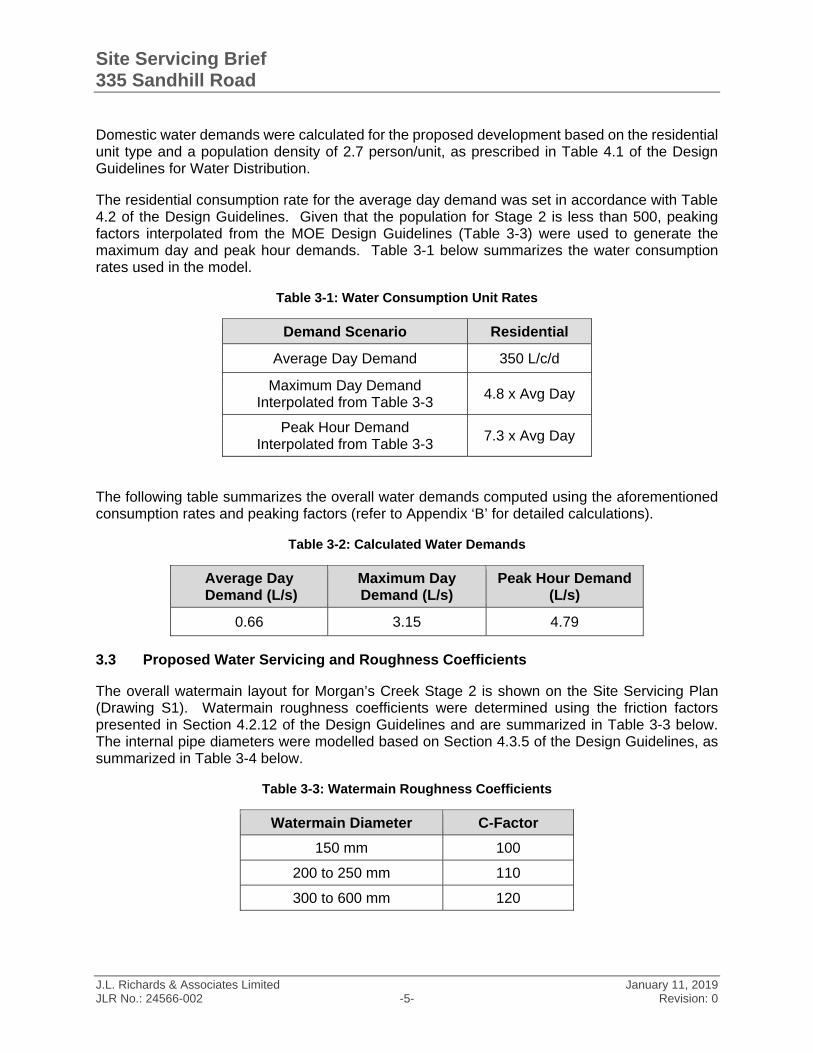
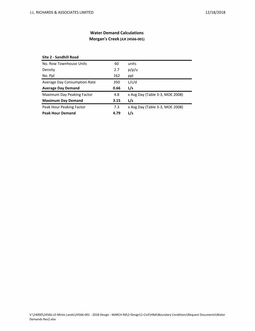
The residential consumption rate for the average day demand was set in accordance with Table 4.2 of the Design Guidelines. Given that the population for Stage 2 is less than 500, peaking factors interpolated from the MOE Design Guidelines (Table 3-3) were used to generate the maximum day and peak hour demands. Table 3-1 below summarizes the water consumption rates used in the model.
Table 3-1: Water Consumption Unit Rates
Demand Scenario Residential
Average Day Demand 350 L/c/d
Maximum Day Demand Interpolated from Table 3-3
4.8 x Avg Day
Peak Hour Demand Interpolated from Table 3-3
7.3 x Avg Day
The following table summarizes the overall water demands computed using the aforementioned consumption rates and peaking factors (refer to Appendix ‘B’ for detailed calculations).
Table 3-2: Calculated Water Demands
Average Day Demand (L/s)
Maximum Day Demand (L/s)
Peak Hour Demand (L/s)
0.66 3.15 4.79
3.3 Proposed Water Servicing and Roughness Coefficients
The overall watermain layout for Morgan’s Creek Stage 2 is shown on the Site Servicing Plan (Drawing S1). Watermain roughness coefficients were determined using the friction factors presented in Section 4.2.12 of the Design Guidelines and are summarized in Table 3-3 below. The internal pipe diameters were modelled based on Section 4.3.5 of the Design Guidelines, as summarized in Table 3-4 below.
Table 3-3: Watermain Roughness Coefficients
Watermain Diameter C-Factor
150 mm 100
200 to 250 mm 110
300 to 600 mm 120
Site Servicing Brief 335 Sandhill Road
J.L. Richards & Associates Limited January 11, 2019 JLR No.: 24566-002 -6- Revision: 0
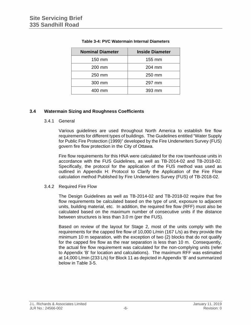
Table 3-4: PVC Watermain Internal Diameters
Nominal Diameter Inside Diameter
150 mm 155 mm
200 mm 204 mm
250 mm 250 mm
300 mm 297 mm
400 mm 393 mm
3.4 Watermain Sizing and Roughness Coefficients
3.4.1 General
Various guidelines are used throughout North America to establish fire flow requirements for different types of buildings. The Guidelines entitled “Water Supply for Public Fire Protection (1999)” developed by the Fire Underwriters Survey (FUS) govern fire flow protection in the City of Ottawa.
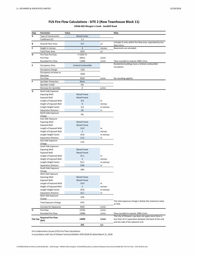
Fire flow requirements for this HNA were calculated for the row townhouse units in accordance with the FUS Guidelines, as well as TB-2014-02 and TB-2018-02. Specifically, the protocol for the application of the FUS method was used as outlined in Appendix H: Protocol to Clarify the Application of the Fire Flow calculation method Published by Fire Underwriters Survey (FUS) of TB-2018-02.
3.4.2 Required Fire Flow
The Design Guidelines as well as TB-2014-02 and TB-2018-02 require that fire flow requirements be calculated based on the type of unit, exposure to adjacent units, building material, etc. In addition, the required fire flow (RFF) must also be calculated based on the maximum number of consecutive units if the distance between structures is less than 3.0 m (per the FUS).
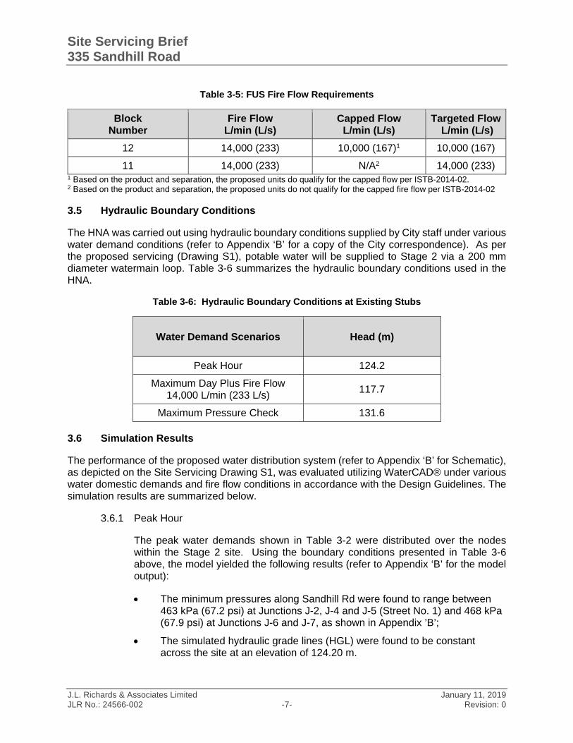
Based on review of the layout for Stage 2, most of the units comply with the requirements for the capped fire flow of 10,000 L/min (167 L/s) as they provide the minimum 10 m separation, with the exception of two (2) blocks that do not qualify for the capped fire flow as the rear separation is less than 10 m. Consequently, the actual fire flow requirement was calculated for the non-complying units (refer to Appendix ‘B’ for location and calculations). The maximum RFF was estimated at 14,000 L/min (233 L/s) for Block 11 as depicted in Appendix ‘B’ and summarized below in Table 3-5.
Site Servicing Brief 335 Sandhill Road
J.L. Richards & Associates Limited January 11, 2019 JLR No.: 24566-002 -7- Revision: 0
Table 3-5: FUS Fire Flow Requirements
Block Number
Fire Flow L/min (L/s)
Capped Flow L/min (L/s)
Targeted Flow L/min (L/s)
12 14,000 (233) 10,000 (167)1 10,000 (167)
11 14,000 (233) N/A2 14,000 (233) 1 Based on the product and separation, the proposed units do qualify for the capped flow per ISTB-2014-02. 2 Based on the product and separation, the proposed units do not qualify for the capped fire flow per ISTB-2014-02
3.5 Hydraulic Boundary Conditions
The HNA was carried out using hydraulic boundary conditions supplied by City staff under various water demand conditions (refer to Appendix ‘B’ for a copy of the City correspondence). As per the proposed servicing (Drawing S1), potable water will be supplied to Stage 2 via a 200 mm diameter watermain loop. Table 3-6 summarizes the hydraulic boundary conditions used in the HNA.
Table 3-6: Hydraulic Boundary Conditions at Existing Stubs
Water Demand Scenarios Head (m)
Peak Hour 124.2
Maximum Day Plus Fire Flow 14,000 L/min (233 L/s)
117.7
Maximum Pressure Check 131.6
3.6 Simulation Results
The performance of the proposed water distribution system (refer to Appendix ‘B’ for Schematic), as depicted on the Site Servicing Drawing S1, was evaluated utilizing WaterCAD® under various water domestic demands and fire flow conditions in accordance with the Design Guidelines. The simulation results are summarized below.
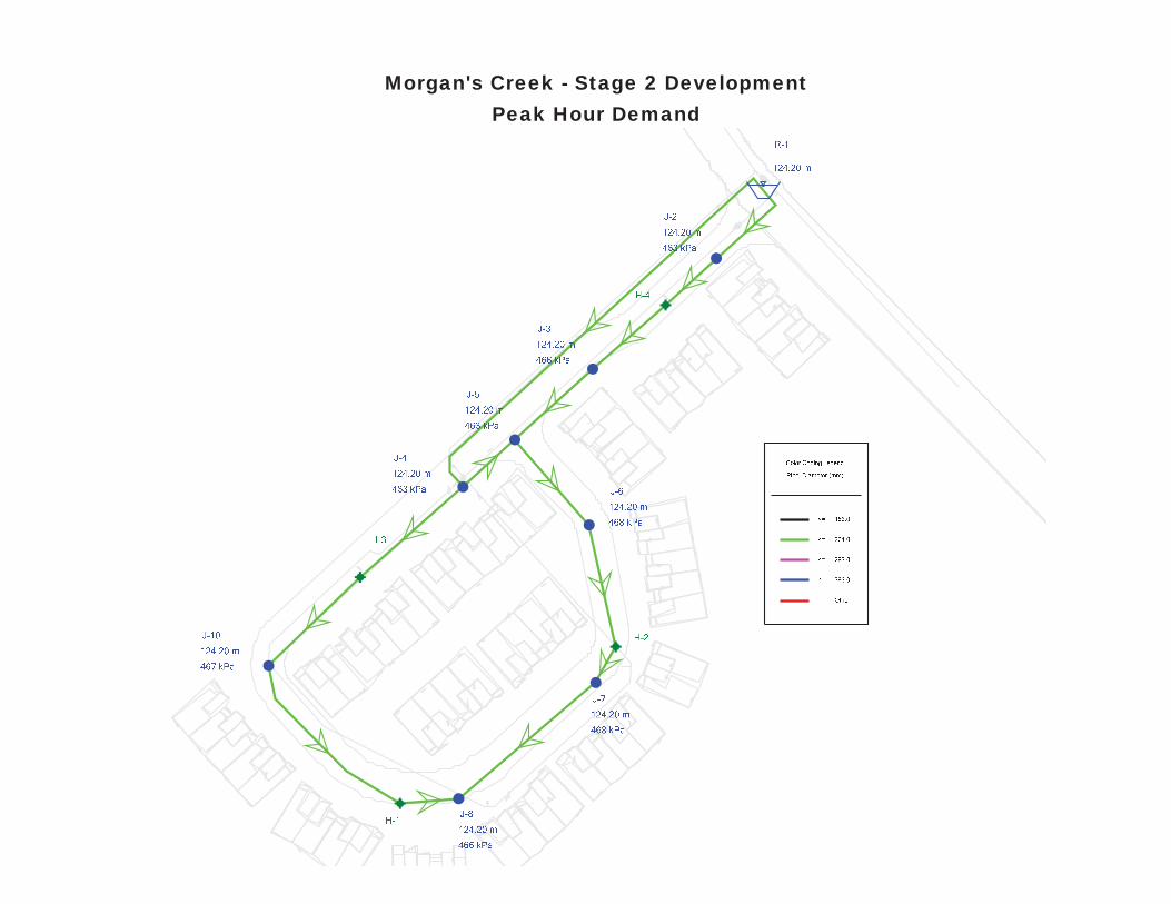
3.6.1 Peak Hour
The peak water demands shown in Table 3-2 were distributed over the nodes within the Stage 2 site. Using the boundary conditions presented in Table 3-6 above, the model yielded the following results (refer to Appendix ‘B’ for the model output):
The minimum pressures along Sandhill Rd were found to range between 463 kPa (67.2 psi) at Junctions J-2, J-4 and J-5 (Street No. 1) and 468 kPa (67.9 psi) at Junctions J-6 and J-7, as shown in Appendix ’B’;
The simulated hydraulic grade lines (HGL) were found to be constant across the site at an elevation of 124.20 m.
Site Servicing Brief 335 Sandhill Road
J.L. Richards & Associates Limited January 11, 2019 JLR No.: 24566-002 -8- Revision: 0
Based on the above simulation results, the minimum pressure criterion of 276 kPa (40 psi) will be exceeded everywhere within Stage 2.
3.6.2 Maximum Day plus Fire Flow
To ensure adequate fire protection, the maximum day demand shown in Table 3-2 was simulated simultaneously with the fire flow along the distribution system within Stage 2. This simulation was carried out using the boundary condition presented in Table 3-6. The conservative RFF of 14,000 L/min (233 L/s) was used for the analysis.
The fire flow simulation was carried out by allowing WaterCAD® to calculate the maximum fire flow availability that can be drawn from each hydrant without allowing any part of the system to experience pressures less than 140 kPa (20 psi), recognizing that hydrants have limited capacity. The simulation results showed that 95 L/s (the maximum fire flow that can be supplied by a hydrant per ISTB-2018-02) can be drawn from each proposed hydrant within Stage 2 while maintaining a minimum system pressure of 140 kPa.
The simulation results (Appendix ’B’) show that the proposed water distribution system is capable of delivering fire flows ranging between 17,400 L/min (290 L/s) and 31,380 L/min (523 L/s) within Stage 2 under the 14,000 L/min (233 L/s) supply head (refer to Appendix ’B’). Hence, the RFF can be fulfilled everywhere within Stage 2. At the time of detailed design, hydrant spacing will be carried out in accordance with their limitations as per ISTB-2018-02.
3.6.3 Maximum HGL
An analysis is generally required to ensure that the maximum pressure constraint of 552 kPa (80 psi) is not exceeded. The maximum HGL condition was simulated using average day demands within Stage 2 to determine the need to incorporate pressure reducing valves (PRVs). Based on the boundary condition shown in Table 3-6, the simulation results are as follows:
The maximum pressures were found to range between 535 kPa (77.6 psi) and 540 kPa (78.3 psi) as shown in Appendix ‘B’; and
The simulated hydraulic grade lines were found to be constant at 131.60 m within Stage 2.
These maximum pressures are below the maximum pressure constraint of 552 kPa (80 psi) and PRVs are not anticipated to be required.
Site Servicing Brief 335 Sandhill Road
J.L. Richards & Associates Limited January 11, 2019 JLR No.: 24566-002 -9- Revision: 0
4.0 Wastewater Servicing
4.1 Design Criteria
Local sanitary sewers for Stage 2 of Morgan’s Creek will be designed in accordance with the City of Ottawa Sewer Design Guidelines (2012) and Technical Bulletins. Sanitary sewers will be designed in accordance with the design parameters summarized in Table 4-1 below.
Table 4-1: Wastewater Servicing Design Criteria
Design Criteria Design Value Reference
Residential average flow 280 L/cap/day ISTB-2018-01
Residential peaking factor Harmon Formula x 0.8 ISTB-2018-01
Commercial average flow 28,000 L/gross ha/day ISTB-2018-01
ICI peaking factor(1) 1.0/1.5 ISTB-2018-01
Total Infiltration 0.33 L/s/ha ISTB-2018-01
Minimum velocity 0.6 m/s OSDG Section 6.1.2.2
Maximum velocity 3.0 m/s OSDG Section 6.1.2.2
Manning Roughness Coefficient
(for smooth wall pipes) 0.013
Section 6.1.8.2 OSDG
Minimum allowable slopes Varies Table 6.2, Section
6.1.2.2, OSDG
Population Density Towns: 2.7 pers/unit Table 4.2
Section 4.3, OSDG
(1) 1.5 if ICI contribution >20%, 1.0 otherwise
4.2 Proposed Sanitary Sewer Servicing and Calculations
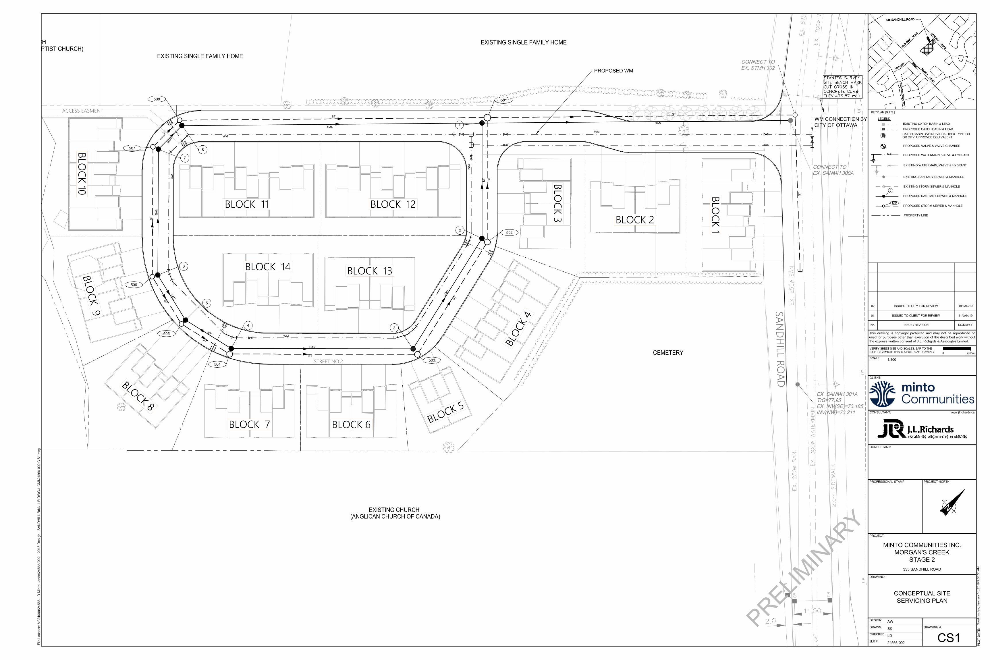
It is proposed to collect and convey wastewater generated by the Stage 2 lands (1.59 ha) via a local 200 mm diameter collection system, which will discharge into the existing Sandhill Road 250 mm diameter sanitary sewer system at existing MH300A. The local 200 mm diameter sanitary sewer system being proposed is shown on the Conceptual Site Servicing (Drawing CS1) attached to this Servicing Brief.
Sanitary servicing for the Briar Ridge Subdivision (Phase 2) identified the Sandhill Road 250 mm diameter sanitary sewer as the dedicated sanitary outlet for Morgan’s Creek Stage 2 as depicted on IBI’s Drawing 501-1 (Appendix ‘C’). Based on IBI’s sanitary sewer design calculations, part of the design capacity of 14.17 L/s for sanitary sewer reach Stub to 300A was allocated to Morgan’s Creek Stage 2. The Sandhill Road 250 mm diameter sanitary sewer was designed based on an
Site Servicing Brief 335 Sandhill Road
J.L. Richards & Associates Limited January 11, 2019 JLR No.: 24566-002 -10- Revision: 0
overall service area of 7.49 ha and overall population of 770. Given that Morgan’s Creek Stage 2 represents approximately 21% of the area (1.59 ha / 7.49 ha) and population (162 cap / 770 cap), its assigned capacity should be consistent on a pro-rata basis. Consequently, Stage 2’s capacity should be 21% of the total capacity of 14.17 L/s. which is 2.98 L/s.
The proposed layout for Stage 2 of Morgan’s Creek includes 60 townhouse units. Based on the proposed servicing for the subdivision (see Drawing CS1) and the design parameters for residential developments listed above in Table 4-1, a peak sanitary flow of 2.38 L/s was calculated (refer to Table 4-2 below for a summary of conceptual peak flows).
Table 4-2: Peak Wastewater Flows
Land Allocation
Population(1) Area Average
Flow Peaking Factor(2)
Peak Flow
Infiltration Flow(3)
Total Flow
Residential / Park / SWM
162 cap 1.59 ha 280
3.54 1.86 L/s 0.52 L/s 2.38 L/s L/cap/day
TOTAL CONCEPTUAL PEAK FLOW: 2.38 L/s (1) Based on 2.7 person/unit for townhomes and back-to-backs as per the City of Ottawa Sewer Design Guidelines. (2) Based on Harmon Peaking Factor Equation (3) Based on 0.33 L/s/ha infiltration allowance as per the City Technical Bulletin ISTB-2018-01.
Given the design basis of the Sandhill Road 250 mm diameter sanitary sewer, the theoretical peak wastewater flow of 2.38 L/s for Stage 2 is well below the prorated peak flow of 2.98 L/s described above. Therefore, there is sufficient capacity in the Sandhill Road sanitary sewer top to accommodate the wastewater flows from Stage 2.
4.3 Summary and Conclusions
Based on the above calculations, it is recommended that conceptual sanitary servicing shown on Drawing CS1 (at the back of the Report) be accepted by the City as this local system can accommodate peak wastewater flows from Stage 2 of Morgan’s Creek. Given the prorated capacity of the Sandhill Road 250 mm diameter sanitary sewer, the theoretical peak flows from Stage 2 can be accommodated by this dedicated sanitary sewer outlet.
Site Servicing Brief 335 Sandhill Road
J.L. Richards & Associates Limited January 11, 2019 JLR No.: 24566-002 -11- Revision: 0
5.0 Storm Servicing and Stormwater Management
5.1 General
This section of the Report presents the analysis (conceptual) completed to confirm that the existing and proposed storm sewers and stormwater management systems can accommodate Stage 2 of Morgan’s Creek in accordance with their design intent.
5.2 Storm Criteria
As part of the Briar Ridge project (Phase 2), a storm sewer was identified and constructed as the dedicated storm sewer outlet for the Sandhill Road site (1.59 ha). Based on the information shown on Drawing 500-1 and on the Storm Sewer Design Sheet (Appendix D), capacity was allocated into the Sandhill Road 675 mm diameter storm sewer for Morgan’s Creek Stage 2 (Sandhill Road site). Once captured, runoff will then be conveyed northerly along the Sandhill Road storm sewer and will eventually outlet into a stormwater management facility for water quality and quantity control. This facility, referred to by the City as the Shirley’s Brook East SWMF #2 (or SWM Facility “C” by Novatech), is located in the northwestern quadrant of the Klondike Road March Valley Road intersection.
Based on IBI’s design (refer to appendix ‘D’ for design information), storm servicing of the external area (7.18 ha) was developed with the following criteria:
an allowable minor system unit flow rate of 85 L/s/ha;
a minimum on-site detention constraint of 50 m3/ha based on a runoff coefficient (C) of 0.45.
Given that a weighted average C coefficient of 0.65 is more representative of terrace townhouse developments, the on-site storage requirement of 50 m3/ha should be increased to ensure that the integrity of the downstream stormwater management system is preserved. At detailed design, it is proposed to revisit the on-site storage volume requirements based on the final layout and calculated C coefficient. However, for the purpose of this Servicing Brief, stormwater management calculations were carried out assuming full retention of the 1:100 year storm based on a C of 0.65 (refer to Section 5.3 for details).
Based on the above, the following summarizes the servicing constraints for the Sandhill Road site:
Minor system flows from Stage 2 must be limited to 85 L/s/ha prior to discharge into the Sandhill Road 675 mm diameter sewer as per the calculations conducted by IBI as part of the Briar Ridge (Phase 2) Subdivision. Based on this design constraint and an area of 1.59 ha minor system flows generated by Stage 2 must be limited to 135.15 L/s.
In terms of major overland flow and for the purpose of this Servicing Brief, it was assumed that servicing of Stage 2 must incorporate sufficient on-site storage volume to detain the 1:100 year storm while limiting minor system flows to 135.15 L/s. Beyond the 1:100 year storm, excess flows can be conveyed overland to either Shirley’s Brook or Sandhill Road. However, during detailed design, a portion of the flow may be uncontrolled and directed to
Site Servicing Brief 335 Sandhill Road
J.L. Richards & Associates Limited January 11, 2019 JLR No.: 24566-002 -12- Revision: 0
Shirley’s Brook and Sandhill Road due to grading constraints. The portion of uncontrolled flow will be determined during detailed design.
As previously noted, Shirley’s Brook bisects the March Road site and Sandhill Road site. The review of the Flood Risk Map for Shirley’s Brook (1989) shows a floodplain elevation of ±73.8 m.
5.3 Proposed Storm Servicing and Calculations
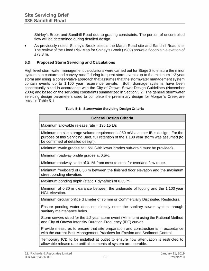
High level stormwater management calculations were carried out for Stage 2 to ensure the minor system can capture and convey runoff during frequent storm events up to the minimum 1:2 year storm and using a conservative approach that assumes that the stormwater management system contain events up to 1:100 year recurrence on-site. Both drainage systems have been conceptually sized in accordance with the City of Ottawa Sewer Design Guidelines (November 2004) and based on the servicing constraints summarized in Section 5.2. The general stormwater servicing design parameters used to complete the preliminary design for Morgan’s Creek are listed in Table 5-1.
Table 5-1: Stormwater Servicing Design Criteria
General Design Criteria
Maximum allowable release rate = 135.15 L/s
Minimum on-site storage volume requirement of 50 m3/ha as per IBI’s design. For the purpose of this Servicing Brief, full retention of the 1:100 year storm was assumed (to be confirmed at detailed design).
Minimum swale grades at 1.5% (with lower grades sub-drain must be provided).
Minimum roadway profile grades at 0.5%.
Minimum roadway slope of 0.1% from crest to crest for overland flow route.
Minimum freeboard of 0.30 m between the finished floor elevation and the maximum street ponding elevation.
Maximum ponding depth (static + dynamic) of 0.35 m.
Minimum of 0.30 m clearance between the underside of footing and the 1:100 year HGL elevation.
Minimum circular orifice diameter of 75 mm or Commercially Distributed Restrictors.
Ensure ponding water does not directly enter the sanitary sewer system through sanitary maintenance holes.
Storm sewers sized for the 1:2 year storm event (Minimum) using the Rational Method and City of Ottawa Intensity-Duration-Frequency (IDF) curves.
Provide measures to ensure that site preparation and construction is in accordance with the current Best Management Practices for Erosion and Sediment Control.
Temporary ICD to be installed at outlet to ensure flow attenuation is restricted to allowable release rate until all elements of system are operable.
Site Servicing Brief 335 Sandhill Road
J.L. Richards & Associates Limited January 11, 2019 JLR No.: 24566-002 -13- Revision: 0
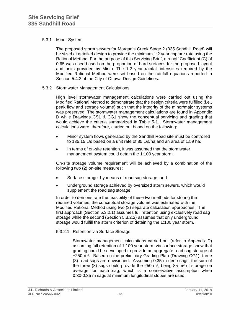
5.3.1 Minor System
The proposed storm sewers for Morgan’s Creek Stage 2 (335 Sandhill Road) will be sized at detailed design to provide the minimum 1:2 year capture rate using the Rational Method. For the purpose of this Servicing Brief, a runoff Coefficient (C) of 0.65 was used based on the proportion of hard surfaces for the proposed layout and units provided by Minto. The 1:2 year rainfall intensities required by the Modified Rational Method were set based on the rainfall equations reported in Section 5.4.2 of the City of Ottawa Design Guidelines.
5.3.2 Stormwater Management Calculations
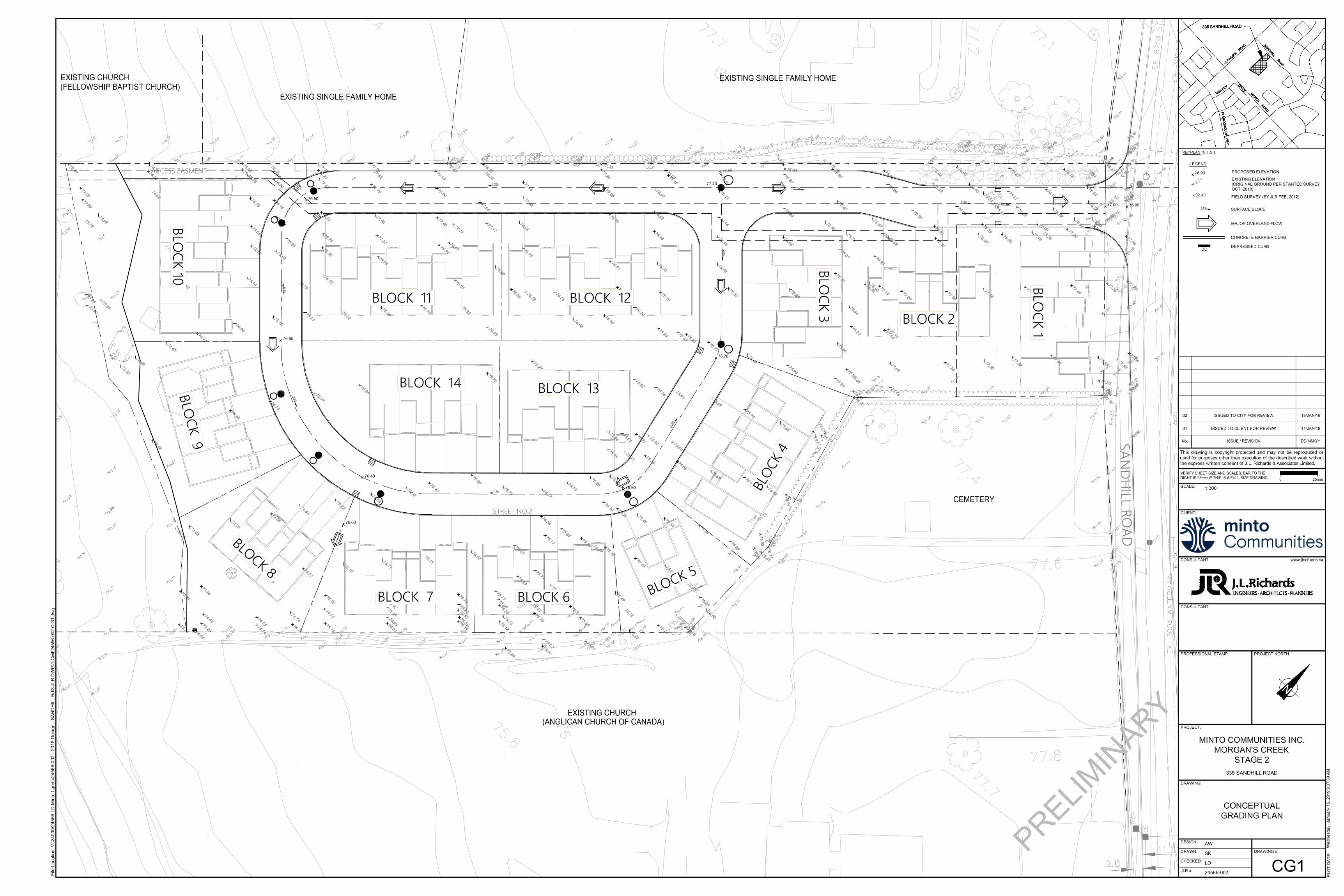
High level stormwater management calculations were carried out using the Modified Rational Method to demonstrate that the design criteria were fulfilled (i.e., peak flow and storage volume) such that the integrity of the minor/major systems was preserved. The stormwater management calculations are found in Appendix D while Drawings CS1 & CG1 show the conceptual servicing and grading that would achieve the criteria summarized in Table 5-1. Stormwater management calculations were, therefore, carried out based on the following:
Minor system flows generated by the Sandhill Road site must be controlled to 135.15 L/s based on a unit rate of 85 L/s/ha and an area of 1.59 ha.
In terms of on-site retention, it was assumed that the stormwater management system could detain the 1:100 year storm.
On-site storage volume requirement will be achieved by a combination of the following two (2) on-site measures:
Surface storage by means of road sag storage; and
Underground storage achieved by oversized storm sewers, which would supplement the road sag storage.
In order to demonstrate the feasibility of these two methods for storing the required volumes, the conceptual storage volume was estimated with the Modified Rational Method using two (2) separate calculation approaches. The first approach (Section 5.3.2.1) assumes full retention using exclusively road sag storage while the second (Section 5.3.2.2) assumes that only underground storage would fulfill the storm criterion of detaining the 1:100 year storm.
5.3.2.1 Retention via Surface Storage
Stormwater management calculations carried out (refer to Appendix D) assuming full retention of 1:100 year storm via surface storage show that grading could be developed to provide an aggregate road sag storage of ±250 m3. Based on the preliminary Grading Plan (Drawing CG1), three (3) road sags are envisioned. Assuming 0.35 m deep sags, the sum of the three (3) sags could provide the 250 m3, being 85 m3 of storage on average for each sag, which is a conservative assumption when 0.30-0.35 m sags at minimum longitudinal slopes are used.
Site Servicing Brief 335 Sandhill Road
J.L. Richards & Associates Limited January 11, 2019 JLR No.: 24566-002 -14- Revision: 0
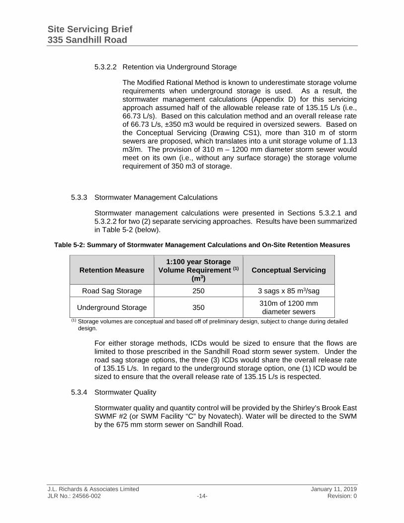
5.3.2.2 Retention via Underground Storage
The Modified Rational Method is known to underestimate storage volume requirements when underground storage is used. As a result, the stormwater management calculations (Appendix D) for this servicing approach assumed half of the allowable release rate of 135.15 L/s (i.e., 66.73 L/s). Based on this calculation method and an overall release rate of 66.73 L/s, ±350 m3 would be required in oversized sewers. Based on the Conceptual Servicing (Drawing CS1), more than 310 m of storm sewers are proposed, which translates into a unit storage volume of 1.13 m3/m. The provision of 310 m – 1200 mm diameter storm sewer would meet on its own (i.e., without any surface storage) the storage volume requirement of 350 m3 of storage.
5.3.3 Stormwater Management Calculations
Stormwater management calculations were presented in Sections 5.3.2.1 and 5.3.2.2 for two (2) separate servicing approaches. Results have been summarized in Table 5-2 (below).
Table 5-2: Summary of Stormwater Management Calculations and On-Site Retention Measures
Retention Measure 1:100 year Storage
Volume Requirement (1) (m3)
Conceptual Servicing
Road Sag Storage 250 3 sags x 85 m3/sag
Underground Storage 350 310m of 1200 mm diameter sewers
(1) Storage volumes are conceptual and based off of preliminary design, subject to change during detailed design.
For either storage methods, ICDs would be sized to ensure that the flows are limited to those prescribed in the Sandhill Road storm sewer system. Under the road sag storage options, the three (3) ICDs would share the overall release rate of 135.15 L/s. In regard to the underground storage option, one (1) ICD would be sized to ensure that the overall release rate of 135.15 L/s is respected.
5.3.4 Stormwater Quality
Stormwater quality and quantity control will be provided by the Shirley’s Brook East SWMF #2 (or SWM Facility “C” by Novatech). Water will be directed to the SWM by the 675 mm storm sewer on Sandhill Road.
Site Servicing Brief 335 Sandhill Road
J.L. Richards & Associates Limited January 11, 2019 JLR No.: 24566-002 -15- Revision: 0
5.4 Summary and Conclusions
The preliminary stormwater servicing and grading as described and shown on Drawing CS1 and CG1 show the Morgan’s Creek Stage 2 can be accommodated by the existing Sandhill Road storm sewer and downstream end-of-pipe facility. Servicing and Grading will be refined at detailed design once the on-site storage method (i.e., road sag or underground storage) has been selected.
Site Servicing Brief 335 Sandhill Road
J.L. Richards & Associates Limited January 11, 2019 JLR No.: 24566-002 -16- Revision: 0
6.0 Summary of Servicing and Recommendations
Servicing of Minto’s Morgan’s Creek Phase 2 development, as depicted on the Conceptual Servicing and Grading Plans, has been accounted for in previous studies completed for the subject area. In General, the lands will be serviced as follows:
Potable water is to be supplied to Morgan’s Creek Stage 2 by an existing 300 mm diameter watermain on Sandhill Road.
Wastewater servicing for Morgan’s Creek Stage 2 is to be provided by the existing 250 mm diameter sanitary sewer along Sandhill Road.
Stormwater servicing is to be provided by the existing 675 mm diameter storm sewer on Sandhill Road. Once captured, runoff will then be conveyed northerly along the Sandhill Road storm sewer and will eventually outlet into a stormwater management facility for water quality and quantity control. This facility, referred to by the City as the Shirley’s Brook East SWMF #2 (or SWM Facility “C” by Novatech)

Appendix ‘A’ – Background Documents

Draft Plan of Subdivision & Location Plan
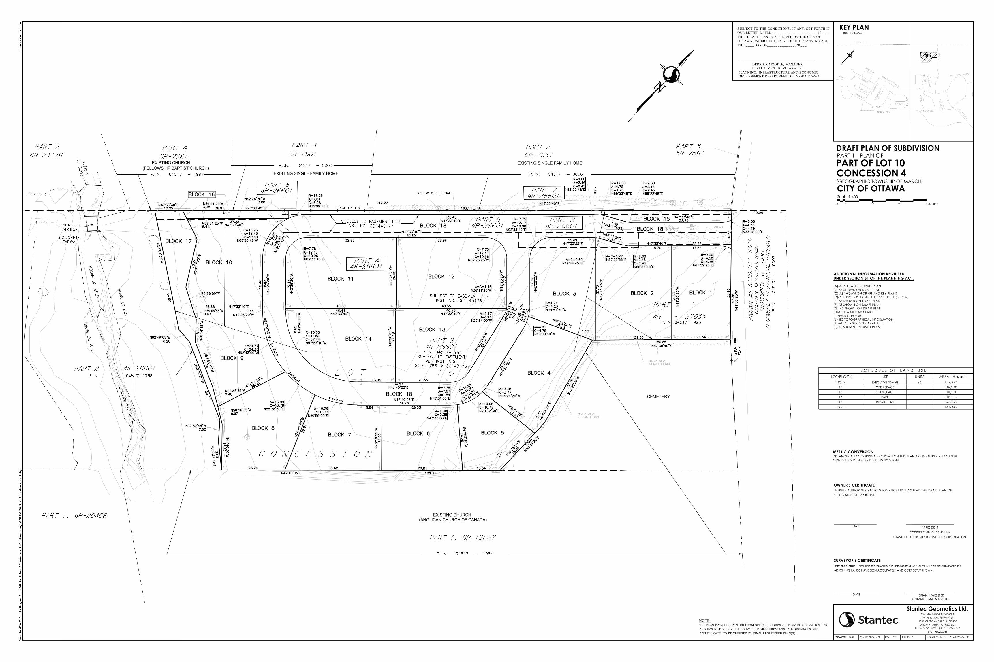
PART OF LOT 10CONCESSION 4(GEOGRAPHIC TOWNSHIP OF MARCH)
CITY OF OTTAWA
N
KEY PLAN(NOT TO SCALE)
*,PRESIDENTDATE
DATE
TMT CTDRAWN: CHECKED: PM:
DEVELOPMENT DEPARTMENT, CITY OF OTTAWA
DRAFT PLAN OF SUBDIVISIONPART 1 - PLAN OF
I HAVE THE AUTHORITY TO BIND THE CORPORATION
####### ONTARIO LIMITED
161613946-130CT PROJECT No.:*FIELD:
SUBJECT TO THE CONDITIONS, IF ANY, SET FORTH IN
OUR LETTER DATED _____________________20____
THIS DRAFT PLAN IS APPROVED BY THE CITY OF
OTTAWA UNDER SECTION 51 OF THE PLANNING ACT.
THIS____DAY OF_____________,20___.
_______________________________________________
DEVELOPMENT REVIEW-WEST
DERRICK MOODIE, MANAGER
PLANNING, INFRASTRUCTURE AND ECONOMIC
NOTE:
THE PLAN DATA IS COMPILED FROM OFFICE RECORDS OF STANTEC GEOMATICS LTD.
AND HAS NOT BEEN VERIFIED BY FIELD MEASUREMENTS. ALL DISTANCES ARE
APPROXIMATE, TO BE VERIFIED BY FINAL REGISTERED PLAN(S).
1 TO 14
S C H E D U L E O F L A N D U S ELOT/BLOCK USE AREA (Ha/ac)
EXECUTIVE TOWNS 60
UNITS1.19/2.95
15 OPEN SPACE
18 PRIVATE ROADTOTAL
0.04/0.09
0.30/0.731.59/3.92
16 OPEN SPACE 0.01/0.0317 PARK 0.05/0.12

Plan of Survey

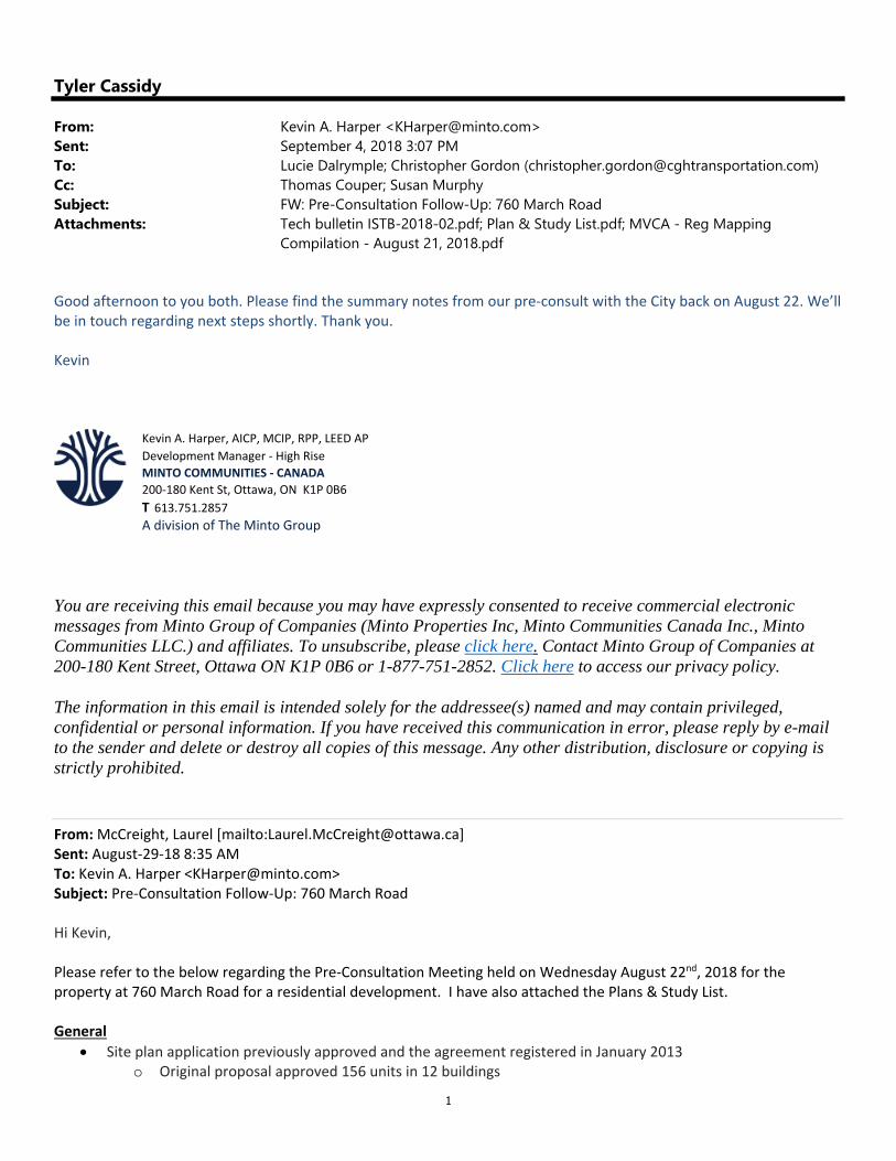
City of Ottawa Pre-Consultation
1
Tyler Cassidy
From: Kevin A. Harper <[email protected]>Sent: September 4, 2018 3:07 PMTo: Lucie Dalrymple; Christopher Gordon ([email protected])Cc: Thomas Couper; Susan MurphySubject: FW: Pre-Consultation Follow-Up: 760 March RoadAttachments: Tech bulletin ISTB-2018-02.pdf; Plan & Study List.pdf; MVCA - Reg Mapping
Compilation - August 21, 2018.pdf
Good afternoon to you both. Please find the summary notes from our pre‐consult with the City back on August 22. We’ll be in touch regarding next steps shortly. Thank you. Kevin
Kevin A. Harper, AICP, MCIP, RPP, LEED AP Development Manager ‐ High Rise MINTO COMMUNITIES ‐ CANADA 200‐180 Kent St, Ottawa, ON K1P 0B6 T 613.751.2857 A division of The Minto Group
You are receiving this email because you may have expressly consented to receive commercial electronic messages from Minto Group of Companies (Minto Properties Inc, Minto Communities Canada Inc., Minto Communities LLC.) and affiliates. To unsubscribe, please click here. Contact Minto Group of Companies at 200-180 Kent Street, Ottawa ON K1P 0B6 or 1-877-751-2852. Click here to access our privacy policy.
The information in this email is intended solely for the addressee(s) named and may contain privileged, confidential or personal information. If you have received this communication in error, please reply by e-mail to the sender and delete or destroy all copies of this message. Any other distribution, disclosure or copying is strictly prohibited.
From: McCreight, Laurel [mailto:[email protected]] Sent: August‐29‐18 8:35 AM To: Kevin A. Harper <[email protected]> Subject: Pre‐Consultation Follow‐Up: 760 March Road Hi Kevin, Please refer to the below regarding the Pre‐Consultation Meeting held on Wednesday August 22nd, 2018 for the property at 760 March Road for a residential development. I have also attached the Plans & Study List. General
Site plan application previously approved and the agreement registered in January 2013 o Original proposal approved 156 units in 12 buildings
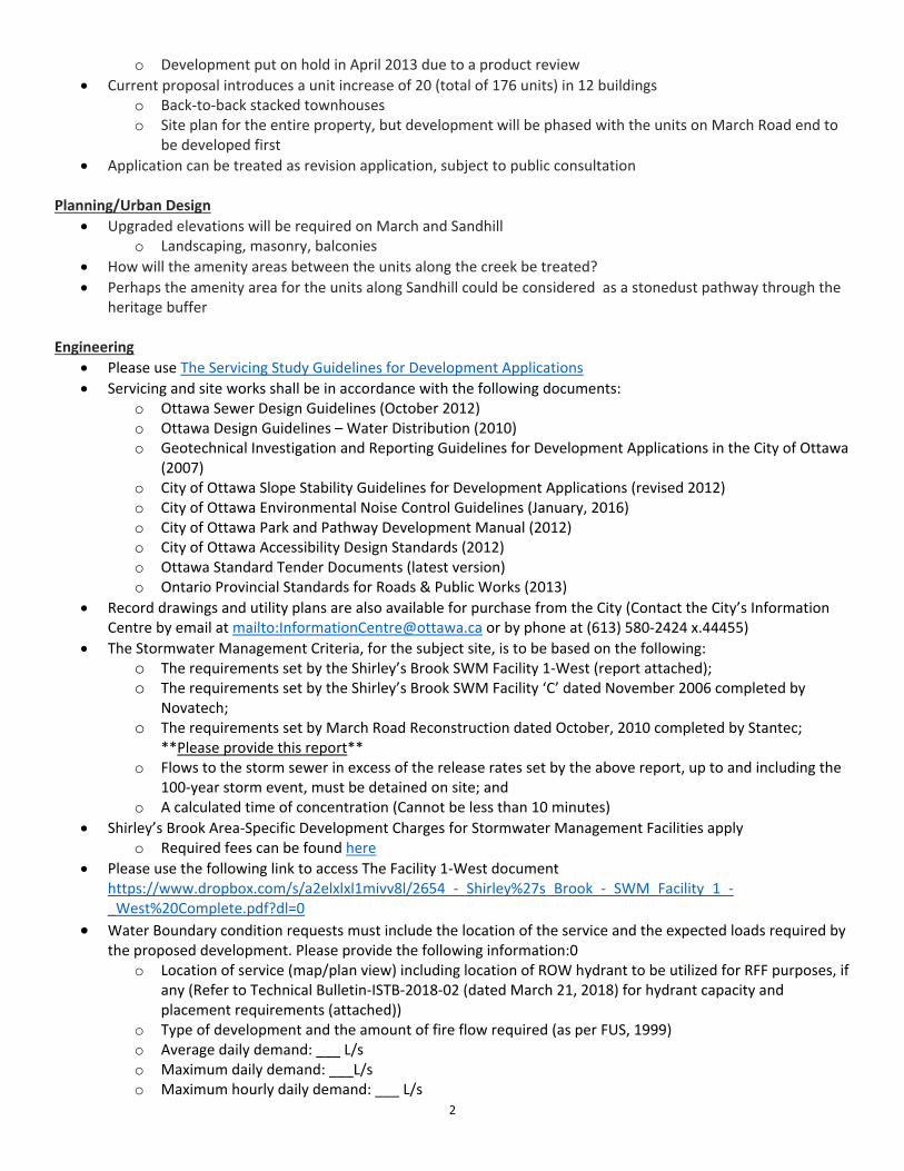
2
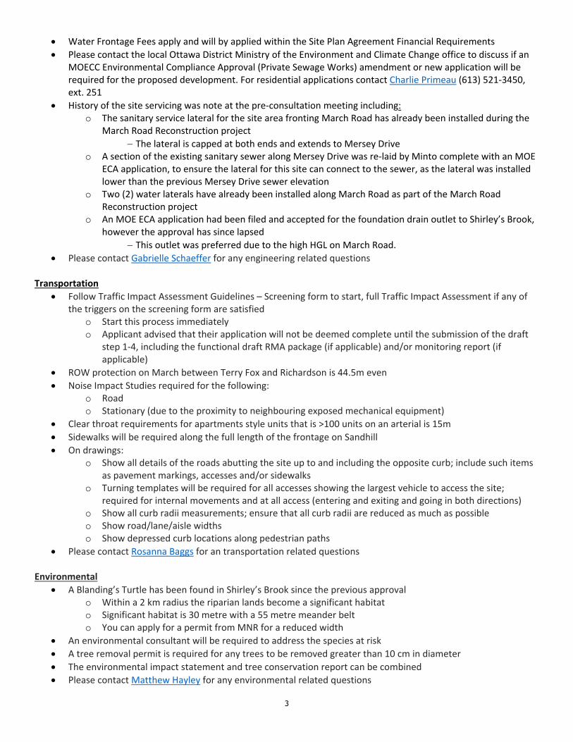
o Development put on hold in April 2013 due to a product review
Current proposal introduces a unit increase of 20 (total of 176 units) in 12 buildings o Back‐to‐back stacked townhouses o Site plan for the entire property, but development will be phased with the units on March Road end to
be developed first
Application can be treated as revision application, subject to public consultation Planning/Urban Design
Upgraded elevations will be required on March and Sandhill o Landscaping, masonry, balconies
How will the amenity areas between the units along the creek be treated?
Perhaps the amenity area for the units along Sandhill could be considered as a stonedust pathway through the heritage buffer
Engineering
Please use The Servicing Study Guidelines for Development Applications
Servicing and site works shall be in accordance with the following documents: o Ottawa Sewer Design Guidelines (October 2012) o Ottawa Design Guidelines – Water Distribution (2010) o Geotechnical Investigation and Reporting Guidelines for Development Applications in the City of Ottawa
(2007) o City of Ottawa Slope Stability Guidelines for Development Applications (revised 2012) o City of Ottawa Environmental Noise Control Guidelines (January, 2016) o City of Ottawa Park and Pathway Development Manual (2012) o City of Ottawa Accessibility Design Standards (2012) o Ottawa Standard Tender Documents (latest version) o Ontario Provincial Standards for Roads & Public Works (2013)
Record drawings and utility plans are also available for purchase from the City (Contact the City’s Information Centre by email at mailto:[email protected] or by phone at (613) 580‐2424 x.44455)
The Stormwater Management Criteria, for the subject site, is to be based on the following: o The requirements set by the Shirley’s Brook SWM Facility 1‐West (report attached); o The requirements set by the Shirley’s Brook SWM Facility ‘C’ dated November 2006 completed by
Novatech; o The requirements set by March Road Reconstruction dated October, 2010 completed by Stantec;
**Please provide this report** o Flows to the storm sewer in excess of the release rates set by the above report, up to and including the
100‐year storm event, must be detained on site; and o A calculated time of concentration (Cannot be less than 10 minutes)
Shirley’s Brook Area‐Specific Development Charges for Stormwater Management Facilities apply o Required fees can be found here
Please use the following link to access The Facility 1‐West document https://www.dropbox.com/s/a2elxlxl1mivv8l/2654_‐_Shirley%27s_Brook_‐_SWM_Facility_1_‐_West%20Complete.pdf?dl=0
Water Boundary condition requests must include the location of the service and the expected loads required by the proposed development. Please provide the following information:0
o Location of service (map/plan view) including location of ROW hydrant to be utilized for RFF purposes, if any (Refer to Technical Bulletin‐ISTB‐2018‐02 (dated March 21, 2018) for hydrant capacity and placement requirements (attached))
o Type of development and the amount of fire flow required (as per FUS, 1999) o Average daily demand: ___ L/s o Maximum daily demand: ___L/s o Maximum hourly daily demand: ___ L/s
3
Water Frontage Fees apply and will by applied within the Site Plan Agreement Financial Requirements
Please contact the local Ottawa District Ministry of the Environment and Climate Change office to discuss if an MOECC Environmental Compliance Approval (Private Sewage Works) amendment or new application will be required for the proposed development. For residential applications contact Charlie Primeau (613) 521‐3450, ext. 251
History of the site servicing was note at the pre‐consultation meeting including: o The sanitary service lateral for the site area fronting March Road has already been installed during the
March Road Reconstruction project
The lateral is capped at both ends and extends to Mersey Drive o A section of the existing sanitary sewer along Mersey Drive was re‐laid by Minto complete with an MOE
ECA application, to ensure the lateral for this site can connect to the sewer, as the lateral was installed lower than the previous Mersey Drive sewer elevation
o Two (2) water laterals have already been installed along March Road as part of the March Road Reconstruction project
o An MOE ECA application had been filed and accepted for the foundation drain outlet to Shirley’s Brook, however the approval has since lapsed
This outlet was preferred due to the high HGL on March Road.
Please contact Gabrielle Schaeffer for any engineering related questions Transportation
Follow Traffic Impact Assessment Guidelines – Screening form to start, full Traffic Impact Assessment if any of the triggers on the screening form are satisfied
o Start this process immediately o Applicant advised that their application will not be deemed complete until the submission of the draft
step 1‐4, including the functional draft RMA package (if applicable) and/or monitoring report (if applicable)
ROW protection on March between Terry Fox and Richardson is 44.5m even
Noise Impact Studies required for the following: o Road o Stationary (due to the proximity to neighbouring exposed mechanical equipment)
Clear throat requirements for apartments style units that is >100 units on an arterial is 15m
Sidewalks will be required along the full length of the frontage on Sandhill
On drawings: o Show all details of the roads abutting the site up to and including the opposite curb; include such items
as pavement markings, accesses and/or sidewalks o Turning templates will be required for all accesses showing the largest vehicle to access the site;
required for internal movements and at all access (entering and exiting and going in both directions) o Show all curb radii measurements; ensure that all curb radii are reduced as much as possible o Show road/lane/aisle widths o Show depressed curb locations along pedestrian paths
Please contact Rosanna Baggs for an transportation related questions Environmental
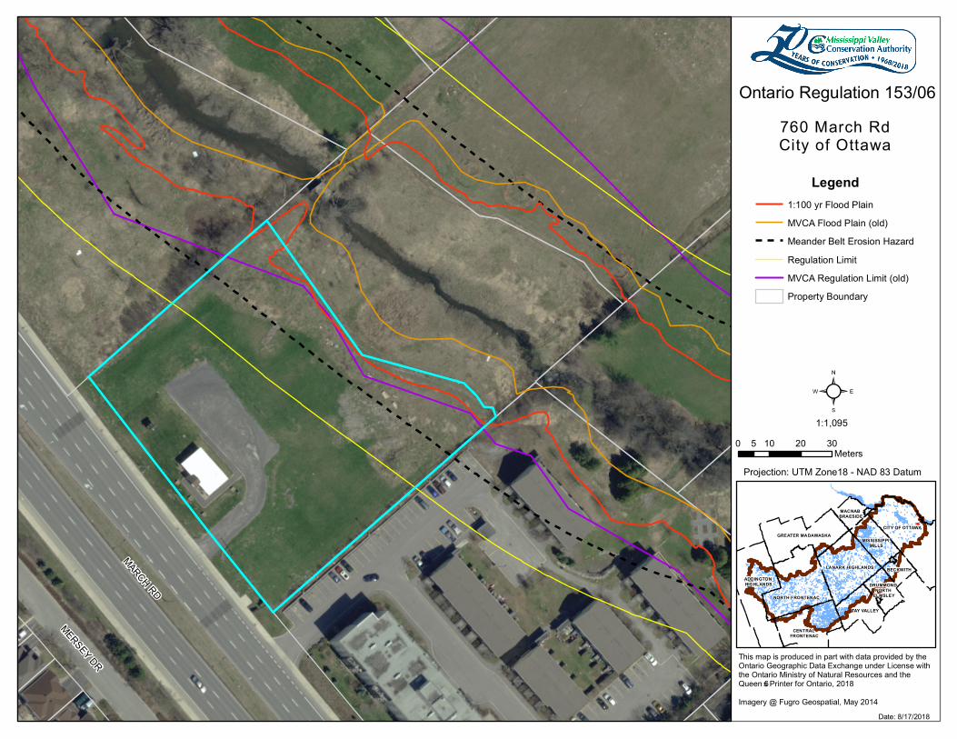
A Blanding’s Turtle has been found in Shirley’s Brook since the previous approval o Within a 2 km radius the riparian lands become a significant habitat o Significant habitat is 30 metre with a 55 metre meander belt o You can apply for a permit from MNR for a reduced width
An environmental consultant will be required to address the species at risk
A tree removal permit is required for any trees to be removed greater than 10 cm in diameter
The environmental impact statement and tree conservation report can be combined
Please contact Matthew Hayley for any environmental related questions
4
MVCA
Updated regulation mapping was completed in November 2017
A meander belt hazard of 87 metres was introduced o A erosion hazard study/meander belt width study can be completed to determine that actual width of
meander belt to be required o Can also work with adjacent landowners
Please contact Niall Oddie at MVCA for any questions Please do not hesitate to contact me if you have any questions. Regards, Laurel Laurel McCreight MCIP, RPP Planner Development Review West Urbaniste Examen des demandes d'aménagement ouest City of Ottawa | Ville d'Ottawa
613.580.2424 ext./poste 16587 ottawa.ca/planning / ottawa.ca/urbanisme
'
This e-mail originates from the City of Ottawa e-mail system. Any distribution, use or copying of this e-mail or the information it contains by other than the intended recipient(s) is unauthorized. Thank you.
Le présent courriel a été expédié par le système de courriels de la Ville d'Ottawa. Toute distribution, utilisation ou reproduction du courriel ou des renseignements qui s'y trouvent par une personne autre que son destinataire prévu est interdite. Je vous remercie de votre collaboration.
'
MERSEY DR
MARCH RD
Legend1:100 yr Flood P la inMVCA Flood P la in (old )Me a nd e r Be lt Erosion Haza rdRe g ula tion Lim itMVCA Re g ula tion Lim it (old )P rope rty Bound a ry
CITY OF OTTAWA
NORTH FRONTENAC
LANARK HIGHLANDS
TAY VALLEY
CENTRAL FRONTENAC
GREATER MADAWASKA
BECKWITHADDINGTON HIGHLANDS
MISSISSIPPI MILLS
MACNAB BRAESIDE
DRUMMOND NORTH
ELMSLEY
0 10 20 305Me te rs
760 Ma rch RdCity of Otta wa
Onta rio Re g ula tion 153/06
Date : 8/17/2018
²1:1,095
This m a p is prod uce d in pa rt with d a ta provid e d by the Onta rio Ge og ra phic Da ta Excha ng e und e r Lice nse with the Onta rio Ministry of Na tura l Re source s a nd the Que e n’s P rinte r for Onta rio, 2018Im a g e ry @ Fug ro Ge ospa tia l, May 2014
P rojection: UTM Z one 18 - NAD 83 Da tum
Last updated September, 2014
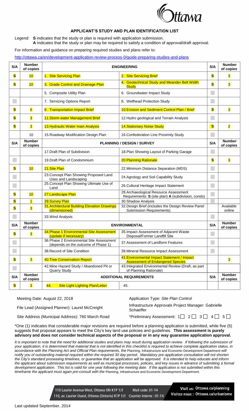
APPLICANT’S STUDY AND PLAN IDENTIFICATION LIST
Legend: S indicates that the study or plan is required with application submission. A indicates that the study or plan may be required to satisfy a condition of approval/draft approval.
For information and guidance on preparing required studies and plans refer to:
http://ottawa.ca/en/development-application-review-process-0/guide-preparing-studies-and-plans
S/A Number
of copies ENGINEERING S/A
Number of copies
S 10 1. Site Servicing Plan 2. Site Servicing Brief S 3
S 10 3. Grade Control and Drainage Plan 4. Geotechnical Study and Meander Belt Width
Study S 3
5. Composite Utility Plan 6. Groundwater Impact Study
7. Servicing Options Report 8. Wellhead Protection Study
S 6 9. Transportation Impact Brief 10. Erosion and Sediment Control Plan / Brief S 3
S 3 11. Storm water Management Brief 12. Hydro geological and Terrain Analysis
S 3 13. Hydraulic Water main Analysis 14. Stationary Noise Study S 2
10 15. Roadway Modification Design Plan 16. Confederation Line Proximity Study
S/A Number
of copies PLANNING / DESIGN / SURVEY S/A
Number of copies
17. Draft Plan of Subdivision 18. Plan Showing Layout of Parking Garage
19. Draft Plan of Condominium 20. Planning Rationale S 3
S 10 21. Site Plan 22. Minimum Distance Separation (MDS)
23. Concept Plan Showing Proposed Land
Uses and Landscaping 24. Agrology and Soil Capability Study
25. Concept Plan Showing Ultimate Use of
Land 26. Cultural Heritage Impact Statement
S 10 27. Landscape Plan 28. Archaeological Resource Assessment Requirements: S (site plan) A (subdivision, condo)
S 1 29. Survey Plan 30. Shadow Analysis
S 3 31. Architectural Building Elevation Drawings
(dimensioned) 32. Design Brief (includes the Design Review Panel
Submission Requirements)
Available online
33. Wind Analysis
S/A Number
of copies ENVIRONMENTAL S/A
Number of copies
S 3 34. Phase 1 Environmental Site Assessment
(update if necessary) 35. Impact Assessment of Adjacent Waste
Disposal/Former Landfill Site
36. Phase 2 Environmental Site Assessment
(depends on the outcome of Phase 1) 37. Assessment of Landform Features
38. Record of Site Condition 39. Mineral Resource Impact Assessment
S 3 40. Tree Conservation Report 41. Environmental Impact Statement / Impact
Assessment of Endangered Species 3
42. Mine Hazard Study / Abandoned Pit or
Quarry Study 43. Integrated Environmental Review (Draft, as part
of Planning Rationale)
S/A Number
of copies ADDITIONAL REQUIREMENTS S/A
Number of copies
S 3 44. Site Light Lighting Plan/Letter 45.
Meeting Date: August 22, 2018 Application Type: Site Plan Control
File Lead (Assigned Planner): Laurel McCreight Infrastructure Approvals Project Manager: Gabrielle Schaeffer
Site Address (Municipal Address): 760 March Road *Preliminary Assessment: 1 2 3 4 5
*One (1) indicates that considerable major revisions are required before a planning application is submitted, while five (5) suggests that proposal appears to meet the City’s key land use policies and guidelines. This assessment is purely advisory and does not consider technical aspects of the proposal or in any way guarantee application approval.
It is important to note that the need for additional studies and plans may result during application review. If following the submission of your application, it is determined that material that is not identified in this checklist is required to achieve complete application status, in accordance with the Planning Act and Official Plan requirements, the Planning, Infrastructure and Economic Development Department will notify you of outstanding material required within the required 30 day period. Mandatory pre-application consultation will not shorten the City’s standard processing timelines, or guarantee that an application will be approved. It is intended to help educate and inform the applicant about submission requirements as well as municipal processes, policies, and key issues in advance of submitting a formal development application. This list is valid for one year following the meeting date. If the application is not submitted within this timeframe the applicant must again pre-consult with the Planning, Infrastructure and Economic Development Department.

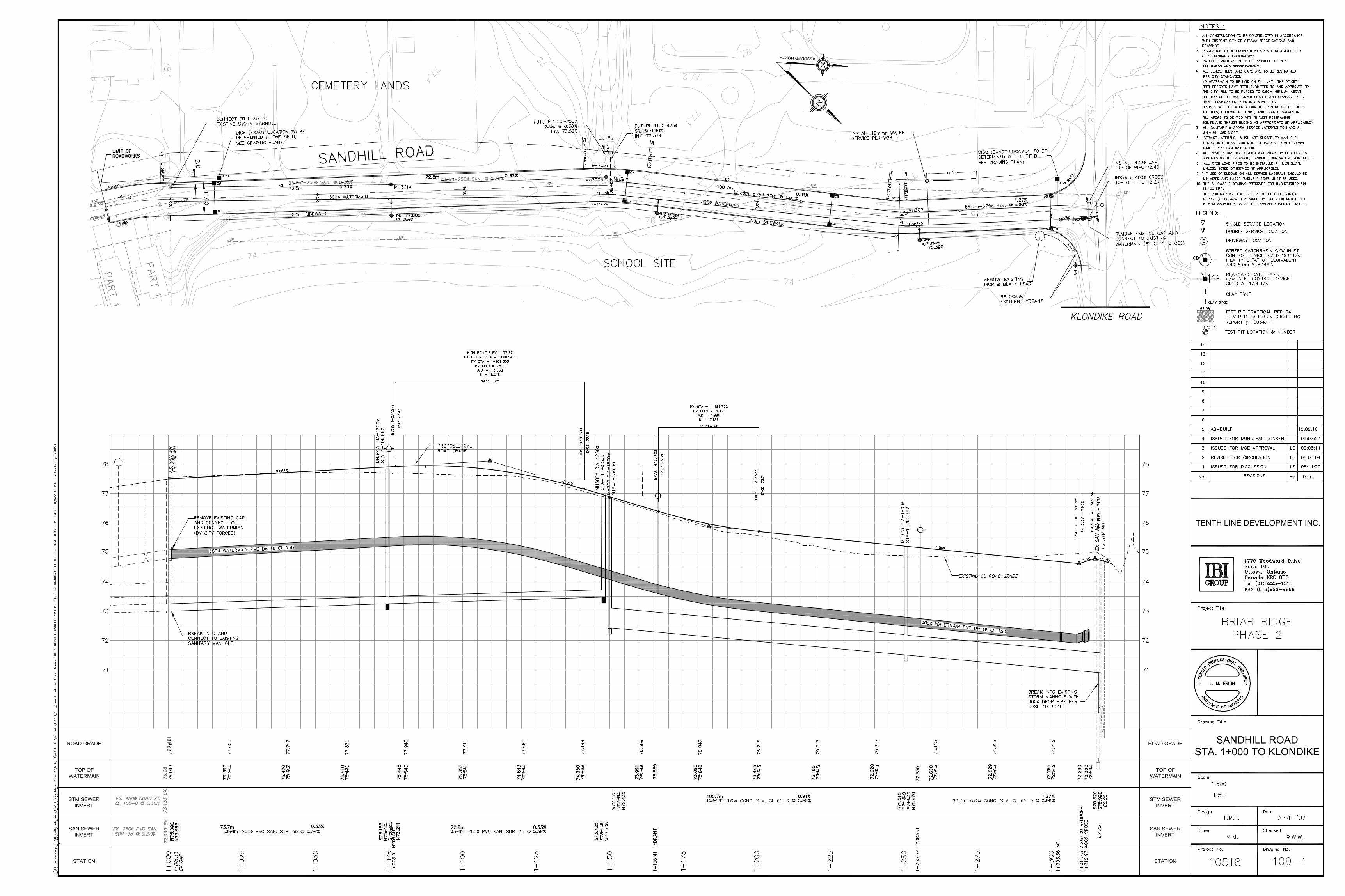
Sandhill Road As-Builts (IBI Group)

Appendix ‘B’ - Watermain

Water Demand and FUS Calculation
J.L. RICHARDS & ASSOCIATES LIMITED 12/18/2018
Water Demand Calculations
Morgan's Creek (JLR 24566‐001)
Site 2 ‐ Sandhill Road
No. Row Townhouse Units 60 units
Density 2.7 p/p/u
No. Ppl 162 ppl
Average Day Consumption Rate 350 L/c/d
Average Day Demand 0.66 L/s
Maximum Day Peaking Factor 4.8 x Avg Day (Table 3‐3, MOE 2008)
Maximum Day Demand 3.15 L/s
Peak Hour Peaking Factor 7.3 x Avg Day (Table 3‐3, MOE 2008)
Peak Hour Demand 4.79 L/s
V:\24000\24566.LD Minto Lands\24566‐001 ‐ 2018 Design ‐ MARCH Rd\2‐Design\1‐Civil\HNA\Boundary Conditions\Request Documents\Water
Demands Rev2.xlsx
J.L. RICHARDS & ASSOCIATES LIMITED 12/18/2018
Step Parameter Value Note
A Type of Construction Wood Frame
Coefficient (C) 1.5
B Ground Floor Area 517 m2 Includes 6 units within fire flow area, separated by less
than 3.0 m.
C Height in storeys 2 storeys Basements are excluded.
Total Floor Area 1034 m2
D Fire Flow Formula F=220C√A
Fire Flow 10611 L/min
Rounded Fire Flow 11000 L/min Flow rounded to nearest 1000 L/min.
E Occupancy Class Limited CombustibleResidential buildings have a limited combustible
occupancyOccupancy Charge ‐15%
Occupancy Increase or
Decrease‐1650
Fire Flow 9350 L/min No rounding applied.
F Sprinkler Protection None
Sprinkler Credit 0%
Decrease for Sprinkler 0 L/min
G North Side Exposure
Exposing Wall: Wood Frame
Exposed Wall: Wood Frame
Length of Exposed Wall: 0.0 m
Height of Exposed Wall: 0 storeys
Length‐Height Factor 0.0 m‐storeys
Separation Distance 93 m
North Side Exposure
Charge0%
East Side Exposure
Exposing Wall: Wood Frame
Exposed Wall: Wood Frame
Length of Exposed Wall: 14.9 m
Height of Exposed Wall: 2 storeys
Length‐Height Factor 29.8 m‐storeys
Separation Distance 3.12 m
East Side Exposure
Charge17%
South Side Exposure
Exposing Wall: Wood Frame
Exposed Wall: Wood Frame
Length of Exposed Wall: 25.1 m
Height of Exposed Wall: 2 storeys
Length‐Height Factor 50.2 m‐storeys
Separation Distance 9.84 m
South Side Exposure
Charge18%
West Side Exposure
Exposing Wall: Wood Frame
Exposed Wall: Wood Frame
Length of Exposed Wall: 14.9 m
Height of Exposed Wall: 2 storeys
Length‐Height Factor 29.8 m‐storeys
Separation Distance 16.1 m
West Side Exposure
Charge12%
Total Exposure Charge 47%The total exposure charge is below the maximum value
of 75%.
Increase for Exposures 4395 L/min
H Fire Flow 13745 L/min
Rounded Fire Flow 14000 L/min Flow rounded to nearest 1000 L/min.
City CapRequired Fire Flow
(RFF)14000 L/min
The City of Ottawa's cap does not apply since there is
less than 10 m separation between the back of the unit
and the side of the adjacent unit.233 L/s
Fire Underwriters Survey (FUS) Fire Flow Calculations
In accordance with City of Ottawa Technical Bulletin ISTB‐2018‐02 dated March 21, 2018
FUS Fire Flow Calculations ‐ SITE 2 (Row Townhouse Block 11)24566‐002 Morgan's Creek ‐ Sandhill Road
V:\24000\24566.LD Minto Lands\24566‐001 ‐ 2018 Design ‐ MARCH Rd\2‐Design\1‐Civil\HNA\Boundary Conditions\Request Documents\24566‐001 FUS Fire Flow ‐ ISTB‐2018‐02.xlsx

Model Schematic
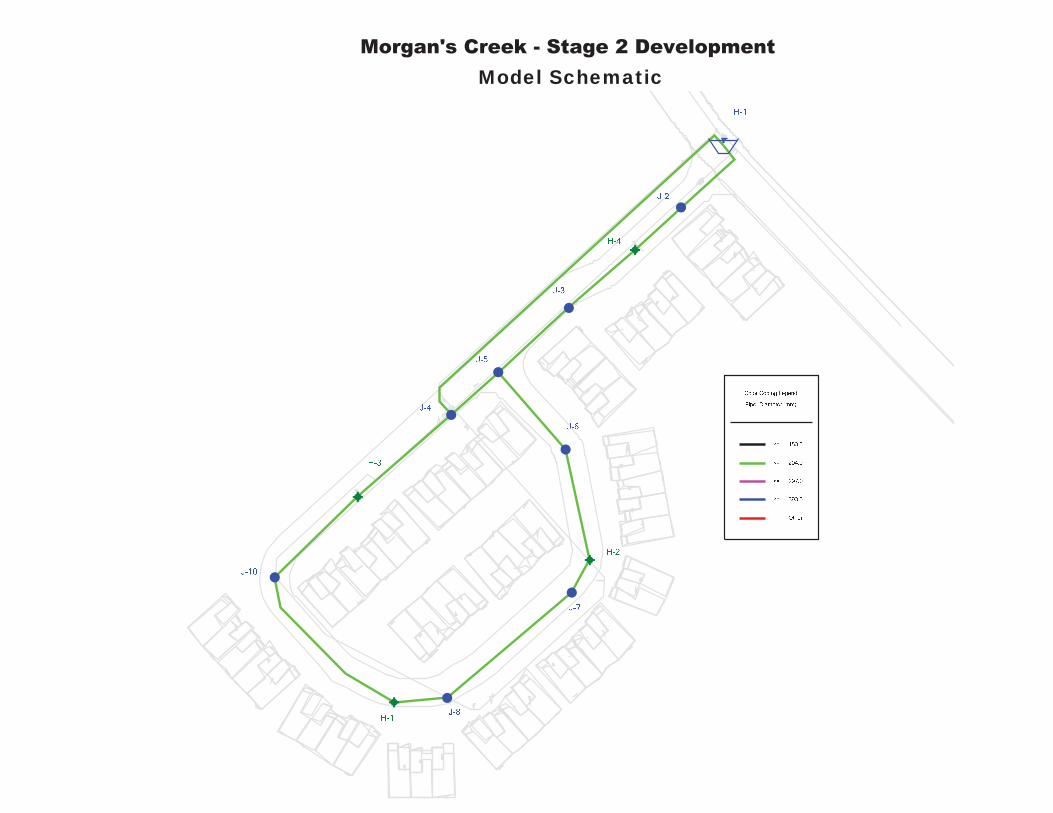
Morgan's Creek - Stage 2 Development Model Schematic
City Correspondence and Hydraulic Boundary Conditions
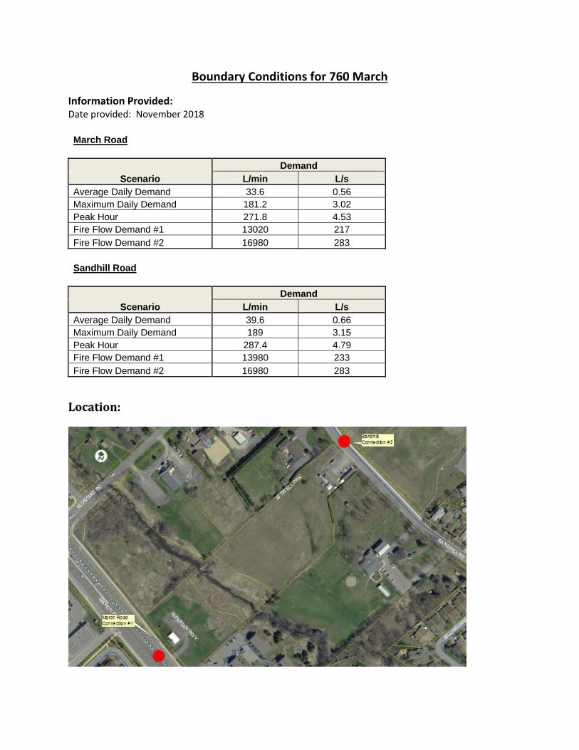
Boundary Conditions for 760 March
Information Provided: Date provided: November 2018 March Road
Demand
Scenario L/min L/s Average Daily Demand 33.6 0.56 Maximum Daily Demand 181.2 3.02 Peak Hour 271.8 4.53 Fire Flow Demand #1 13020 217
Fire Flow Demand #2 16980 283
Sandhill Road
Demand
Scenario L/min L/s Average Daily Demand 39.6 0.66 Maximum Daily Demand 189 3.15 Peak Hour 287.4 4.79 Fire Flow Demand #1 13980 233
Fire Flow Demand #2 16980 283
Location:
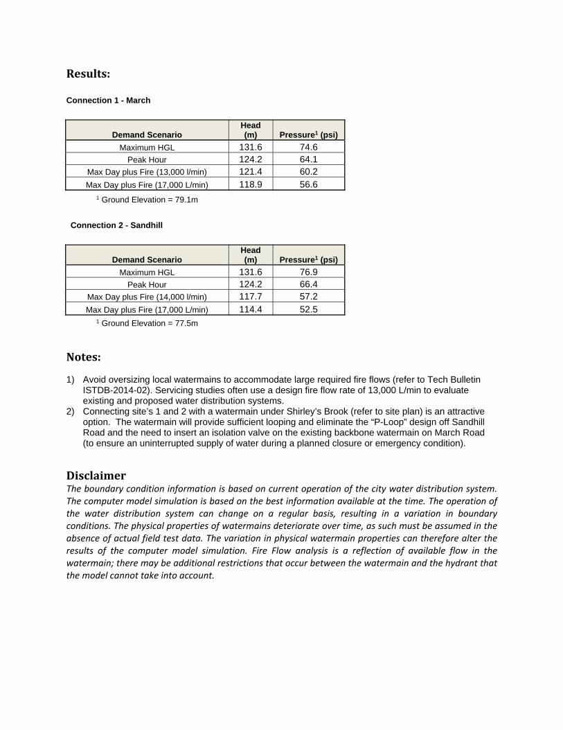
Results:
Connection 1 - March
Demand Scenario Head (m) Pressure1 (psi)
Maximum HGL 131.6 74.6 Peak Hour 124.2 64.1
Max Day plus Fire (13,000 l/min) 121.4 60.2
Max Day plus Fire (17,000 L/min) 118.9 56.6 1 Ground Elevation = 79.1m
Connection 2 - Sandhill
Demand Scenario Head (m) Pressure1 (psi)
Maximum HGL 131.6 76.9 Peak Hour 124.2 66.4
Max Day plus Fire (14,000 l/min) 117.7 57.2
Max Day plus Fire (17,000 L/min) 114.4 52.5 1 Ground Elevation = 77.5m
Notes:
1) Avoid oversizing local watermains to accommodate large required fire flows (refer to Tech Bulletin ISTDB-2014-02). Servicing studies often use a design fire flow rate of 13,000 L/min to evaluate existing and proposed water distribution systems.
2) Connecting site’s 1 and 2 with a watermain under Shirley’s Brook (refer to site plan) is an attractive option. The watermain will provide sufficient looping and eliminate the “P-Loop” design off Sandhill Road and the need to insert an isolation valve on the existing backbone watermain on March Road (to ensure an uninterrupted supply of water during a planned closure or emergency condition).
DisclaimerThe boundary condition information is based on current operation of the city water distribution system. The computer model simulation is based on the best information available at the time. The operation of the water distribution system can change on a regular basis, resulting in a variation in boundary conditions. The physical properties of watermains deteriorate over time, as such must be assumed in the absence of actual field test data. The variation in physical watermain properties can therefore alter the results of the computer model simulation. Fire Flow analysis is a reflection of available flow in the watermain; there may be additional restrictions that occur between the watermain and the hydrant that the model cannot take into account.
1
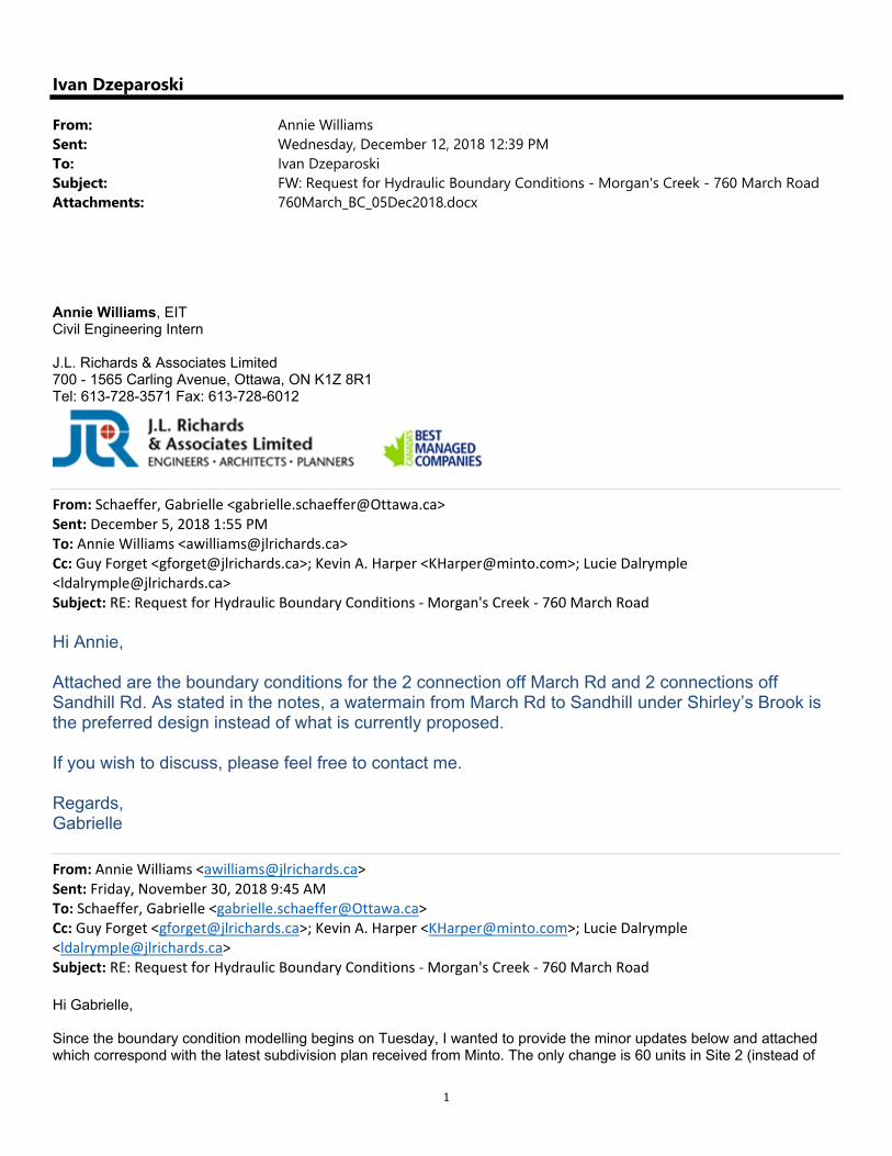
Ivan Dzeparoski
From: Annie WilliamsSent: Wednesday, December 12, 2018 12:39 PMTo: Ivan DzeparoskiSubject: FW: Request for Hydraulic Boundary Conditions - Morgan's Creek - 760 March RoadAttachments: 760March_BC_05Dec2018.docx
Annie Williams, EIT Civil Engineering Intern J.L. Richards & Associates Limited 700 - 1565 Carling Avenue, Ottawa, ON K1Z 8R1 Tel: 613-728-3571 Fax: 613-728-6012
From: Schaeffer, Gabrielle <[email protected]> Sent: December 5, 2018 1:55 PM To: Annie Williams <[email protected]> Cc: Guy Forget <[email protected]>; Kevin A. Harper <[email protected]>; Lucie Dalrymple <[email protected]> Subject: RE: Request for Hydraulic Boundary Conditions ‐ Morgan's Creek ‐ 760 March Road
Hi Annie, Attached are the boundary conditions for the 2 connection off March Rd and 2 connections off Sandhill Rd. As stated in the notes, a watermain from March Rd to Sandhill under Shirley’s Brook is the preferred design instead of what is currently proposed. If you wish to discuss, please feel free to contact me. Regards, Gabrielle
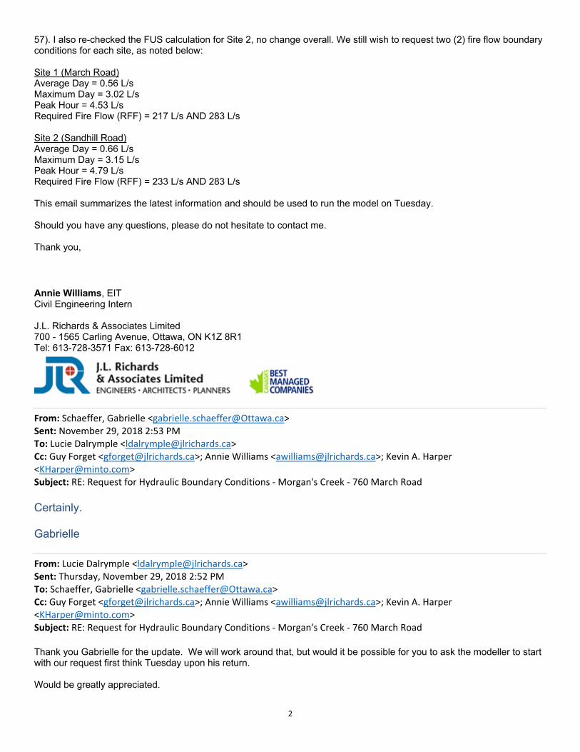
From: Annie Williams <[email protected]> Sent: Friday, November 30, 2018 9:45 AM To: Schaeffer, Gabrielle <[email protected]> Cc: Guy Forget <[email protected]>; Kevin A. Harper <[email protected]>; Lucie Dalrymple <[email protected]> Subject: RE: Request for Hydraulic Boundary Conditions ‐ Morgan's Creek ‐ 760 March Road Hi Gabrielle, Since the boundary condition modelling begins on Tuesday, I wanted to provide the minor updates below and attached which correspond with the latest subdivision plan received from Minto. The only change is 60 units in Site 2 (instead of
2
57). I also re-checked the FUS calculation for Site 2, no change overall. We still wish to request two (2) fire flow boundary conditions for each site, as noted below: Site 1 (March Road) Average Day = 0.56 L/s Maximum Day = 3.02 L/s Peak Hour = 4.53 L/s Required Fire Flow (RFF) = 217 L/s AND 283 L/s Site 2 (Sandhill Road) Average Day = 0.66 L/s Maximum Day = 3.15 L/s Peak Hour = 4.79 L/s Required Fire Flow (RFF) = 233 L/s AND 283 L/s This email summarizes the latest information and should be used to run the model on Tuesday. Should you have any questions, please do not hesitate to contact me. Thank you,
Annie Williams, EIT Civil Engineering Intern J.L. Richards & Associates Limited 700 - 1565 Carling Avenue, Ottawa, ON K1Z 8R1 Tel: 613-728-3571 Fax: 613-728-6012
From: Schaeffer, Gabrielle <[email protected]> Sent: November 29, 2018 2:53 PM To: Lucie Dalrymple <[email protected]> Cc: Guy Forget <[email protected]>; Annie Williams <[email protected]>; Kevin A. Harper <[email protected]> Subject: RE: Request for Hydraulic Boundary Conditions ‐ Morgan's Creek ‐ 760 March Road
Certainly. Gabrielle
From: Lucie Dalrymple <[email protected]> Sent: Thursday, November 29, 2018 2:52 PM To: Schaeffer, Gabrielle <[email protected]> Cc: Guy Forget <[email protected]>; Annie Williams <[email protected]>; Kevin A. Harper <[email protected]> Subject: RE: Request for Hydraulic Boundary Conditions ‐ Morgan's Creek ‐ 760 March Road Thank you Gabrielle for the update. We will work around that, but would it be possible for you to ask the modeller to start with our request first think Tuesday upon his return. Would be greatly appreciated.

3
Thank you Lucie
Lucie Dalrymple, P.Eng. Associate Senior Civil Engineer J.L. Richards & Associates Limited 700 - 1565 Carling Avenue, Ottawa, ON K1Z 8R1 Tel: 613-728-3571 Fax: 613-728-6012
From: Schaeffer, Gabrielle <[email protected]> Sent: November 29, 2018 1:54 PM To: Lucie Dalrymple <[email protected]> Cc: Guy Forget <[email protected]>; Annie Williams <[email protected]> Subject: RE: Request for Hydraulic Boundary Conditions ‐ Morgan's Creek ‐ 760 March Road
Lucie, Unfortunately, Tuesday is the earliest our modelling group can get BCs back to me. One modeler is away until then and the other is in meetings all three days (today, tomorrow and Monday). If you wish to proceed, I will accept the first submission with either: using the old BCs, or no boundary conditions/watermain sizing analysis. Additionally, I will accept a revised Water Servicing section and Water Appendix via email after the formal submittal has been made, but before review, comments are issued. I hope these options help at this time. Regards, Gabrielle
From: Lucie Dalrymple <[email protected]> Sent: Thursday, November 29, 2018 12:22 PM To: Schaeffer, Gabrielle <[email protected]> Cc: Guy Forget <[email protected]>; Annie Williams <[email protected]> Subject: RE: Request for Hydraulic Boundary Conditions ‐ Morgan's Creek ‐ 760 March Road Hi Gabrielle, Unfortunately, the timing in which the boundary conditions will be available (next Tuesday per you email) presents a significant delivery probable from the team of consultants. We have been coordinating this request with the City since October 26, 2018. There was approximately one month lost due to the uncertainty of the existence of the two watermain stubs off of March Road, which was discussed at the August 22, 2018 pre-consultation meeting and which was confirmed in the meeting minutes issued on August 29th, 2018 (copy attached). We understand that it is not you personally calculating the boundary condition, so would you please assist us in coordinating with the responsible City staff to see if these boundary conditions provided to JLR no later than end of day tomorrow? It would be greatly appreciated.
4
There is a lot of coordination efforts on all consultants to prepared a complete submission and when one study cannot be completed at the same time as all others, it presents issues. As Annie mentioned, the submission was to be issued tomorrow (based on a 3 week turn around for the boundary condition requested on October 26, 2018). We managed to push the submission date forward to next Friday, which means that the boundary conditions must be received this week. Please advise if the BC can be provided sooner than next Tuesday. We appreciate your assistance. Thank you, Lucie
Lucie Dalrymple, P.Eng. Associate Senior Civil Engineer J.L. Richards & Associates Limited 700 - 1565 Carling Avenue, Ottawa, ON K1Z 8R1 Tel: 613-728-3571 Fax: 613-728-6012
From: Schaeffer, Gabrielle <[email protected]> Sent: November 29, 2018 11:57 AM To: Annie Williams <[email protected]> Cc: Lucie Dalrymple <[email protected]>; Guy Forget <[email protected]> Subject: RE: Request for Hydraulic Boundary Conditions ‐ Morgan's Creek ‐ 760 March Road
Hi Annie, I touched base with our modelling group. I am expecting to receive the BCs Tuesday. Gabrielle
From: Annie Williams <[email protected]> Sent: Thursday, November 29, 2018 11:43 AM To: Schaeffer, Gabrielle <[email protected]> Cc: Lucie Dalrymple <[email protected]>; Guy Forget <[email protected]> Subject: RE: Request for Hydraulic Boundary Conditions ‐ Morgan's Creek ‐ 760 March Road Hi Gabrielle, Per my voicemail from this morning, please let us know when we can expect to receive these boundary conditions. As mentioned, our original deadline for the March Road design was tomorrow and we have shifted it to next week. We need to prepare our detailed water servicing design within the next few days. Feel free to give me a call if there is something holding this up. Thank you,
5
Annie Williams, EIT Civil Engineering Intern J.L. Richards & Associates Limited 700 - 1565 Carling Avenue, Ottawa, ON K1Z 8R1 Tel: 613-728-3571 Fax: 613-728-6012
From: Annie Williams Sent: November 26, 2018 2:05 PM To: Schaeffer, Gabrielle <[email protected]> Cc: Lucie Dalrymple <[email protected]>; Guy Forget <[email protected]> Subject: RE: Request for Hydraulic Boundary Conditions ‐ Morgan's Creek ‐ 760 March Road Hi Gabrielle, Following our phone conversation, I have attached the revised water demand calculations. As noted, the Site 2 plan has changed slightly to accommodate 57 units. Thank you,
From: Schaeffer, Gabrielle <[email protected]> Sent: November 26, 2018 11:40 AM To: Annie Williams <[email protected]> Subject: RE: Request for Hydraulic Boundary Conditions ‐ Morgan's Creek ‐ 760 March Road
Hi Annie, I just completed my review. FUS calcs look good. Domestic calcs need revision:
Since each population is less than 500 person, please use Table 3-3 of the MOE Design Guidelines for Drinking Water Systems to establish peaking factors for both sites. Please either interpolate the peaking factors or utilize the higher peaking factor which is associated with the lower population in the table (i.e. for 138 person you can use the peaking factors for 100 persons since they are higher than the peaking factors for 150 persons)
The number of units for Site 2 appear to be high. I see 51 units on the plan provided, not 57. Once I have the revised calcs, I can provide the boundary conditions. Regards, Gabrielle
From: Annie Williams <[email protected]> Sent: Friday, November 23, 2018 4:32 PM To: Schaeffer, Gabrielle <[email protected]> Cc: Lucie Dalrymple <[email protected]>; Guy Forget <[email protected]> Subject: RE: Request for Hydraulic Boundary Conditions ‐ Morgan's Creek ‐ 760 March Road Hi Gabrielle, Please let us know if the provided information is sufficient and when we can expect the boundary conditions.
6
Thank you,
Annie Williams, EIT Civil Engineering Intern J.L. Richards & Associates Limited 700 - 1565 Carling Avenue, Ottawa, ON K1Z 8R1 Tel: 613-728-3571 Fax: 613-728-6012
From: Annie Williams Sent: November 22, 2018 10:41 AM To: 'Schaeffer, Gabrielle' <[email protected]> Cc: Lucie Dalrymple <[email protected]>; Guy Forget <[email protected]> Subject: RE: Request for Hydraulic Boundary Conditions ‐ Morgan's Creek ‐ 760 March Road Hi Gabrielle, Minto has slightly revised their layout on the Sandhill site so I have revised the domestic demand calculations (attached). We would also like to request a second boundary condition for fire flow on each of the sites for 17,000 L/min (283 L/s). The City has indicated previously that the boundary conditions can be interpolated should further revisions to the draft plan occur. Let me know if you have any questions and when we can expect to receive the boundary conditions. Thank you,
From: Schaeffer, Gabrielle <[email protected]> Sent: November 20, 2018 10:08 AM To: Annie Williams <[email protected]> Subject: RE: Request for Hydraulic Boundary Conditions ‐ Morgan's Creek ‐ 760 March Road
Hi Annie, Thanks for your voicemail yesterday. I was unaware that water services were already installed for this site (at least fronting March). As of right now, I will proceed with the proposed double connection to March as previous proposed, however I am waiting on approval from operations so we’re not in the clear yet. Please provide me with supporting calcs for your domestic demand calculations. We’re trying to minimize the number of boundary condition requestes we run so we’re doing the water review up front and just doing a check that the circumstances are the same in application review. Regards, Gabrielle
From: Annie Williams <[email protected]> Sent: Friday, October 26, 2018 4:13 PM To: Schaeffer, Gabrielle <[email protected]> Cc: McCreight, Laurel <[email protected]>; Guy Forget <[email protected]>; Lucie Dalrymple

7
<[email protected]>; Thomas Couper <[email protected]>; Kevin A. Harper <[email protected]> Subject: Request for Hydraulic Boundary Conditions ‐ Morgan's Creek ‐ 760 March Road Hi Gabrielle, We would like to obtain updated hydraulic boundary conditions in support of a Site Plan Application for Minto’s development of a residential site (Morgan’s Creek) located at 760 March Road in the City of Ottawa (refer to attached Site Plan). The City previously provided hydraulic boundary conditions for this site back in 2011 (attached). Approvals for the site were granted under Site Plan control; however, the site was never developed. Since that time, the Site Plan has been slightly revised though the general concept remains as follows: The site is bisected by Shirley’s Brook with the western portion (Site 1) fronting onto March Road and the eastern portion (Site 2) fronting onto Sandhill Road. Site 1 includes 60 terrace (duplex) units and is proposed to be serviced from two (2) connections to the existing March Road 400 mm diameter watermain. Site 2 includes 51 row townhouse units and is proposed to be serviced from two (2) connections to the existing 300 mm diameter watermain on Sandhill Road. We request hydraulic boundary conditions for both Site 1 and Site 2 along the existing watermains at the proposed site entrances (as depicted on the Site Plan). Based on the City Design Guidelines, the following demands are anticipated: Site 1 Average Day = 0.56 L/s Maximum Day = 1.40 L/s Peak Hour = 3.07 L/s Required Fire Flow (RFF) = 217 L/s Site 2 Average Day = 0.56 L/s Maximum Day = 1.40 L/s Peak Hour = 3.07 L/s Required Fire Flow (RFF) = 233 L/s Furthermore, if static conditions are expected to fluctuate between existing and future build-out conditions, we would like to obtain both. The RFF was calculated in accordance with the City Design Guidelines for Water Distribution and associated Technical Bulletins, including the latest ISTB-2018-02. Detailed calculations are attached. Should you have any questions or require any further information, please do not hesitate to contact me. Thank you,
Annie Williams, EIT Civil Engineering Intern J.L. Richards & Associates Limited 700 - 1565 Carling Avenue, Ottawa, ON K1Z 8R1 Tel: 613-728-3571 Fax: 613-728-6012
'
This e-mail originates from the City of Ottawa e-mail system. Any distribution, use or copying of this e-mail or the information it contains by other than the intended recipient(s) is unauthorized. Thank you.

Simulation Results – Peak Hour Demand
Peak Hour DemandMorgan's Creek - Stage 2 Development
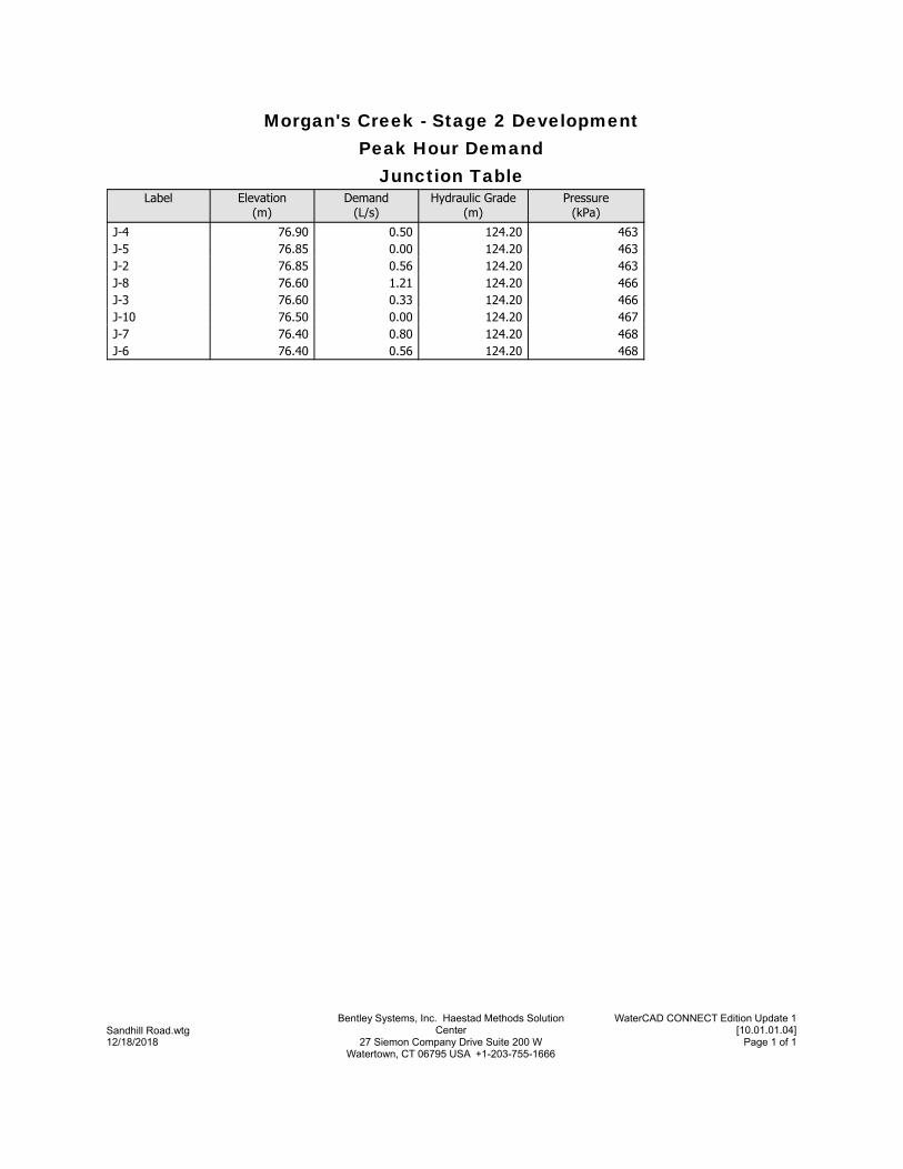
Junction TablePeak Hour Demand
Morgan's Creek - Stage 2 Development
Pressure(kPa)
Hydraulic Grade(m)
Demand(L/s)
Elevation(m)
Label
463124.200.5076.90J-4463124.200.0076.85J-5463124.200.5676.85J-2466124.201.2176.60J-8466124.200.3376.60J-3467124.200.0076.50J-10468124.200.8076.40J-7468124.200.5676.40J-6
Page 1 of 127 Siemon Company Drive Suite 200 W Watertown, CT 06795 USA +1-203-755-1666
12/18/2018
WaterCAD CONNECT Edition Update 1[10.01.01.04]
Bentley Systems, Inc. Haestad Methods Solution CenterSandhill Road.wtg
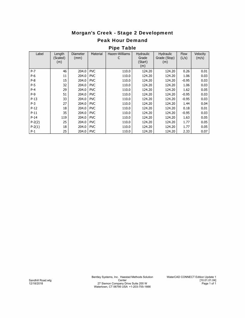
Pipe TablePeak Hour Demand
Morgan's Creek - Stage 2 Development
Velocity(m/s)
Flow(L/s)
Hydraulic Grade (Stop)
(m)
Hydraulic Grade (Start)
(m)
Hazen-Williams C
MaterialDiameter(mm)
Length (Scaled)
(m)
Label
0.010.26124.20124.20110.0PVC204.046P-70.031.06124.20124.20110.0PVC204.011P-60.03-0.95124.20124.20110.0PVC204.015P-80.031.06124.20124.20110.0PVC204.032P-50.051.62124.20124.20110.0PVC204.029P-40.03-0.95124.20124.20110.0PVC204.051P-90.03-0.95124.20124.20110.0PVC204.033P-130.041.44124.20124.20110.0PVC204.027P-30.010.18124.20124.20110.0PVC204.018P-120.03-0.95124.20124.20110.0PVC204.035P-110.051.63124.20124.20110.0PVC204.0119P-140.051.77124.20124.20110.0PVC204.025P-2(2)0.051.77124.20124.20110.0PVC204.018P-2(1)0.072.33124.20124.20110.0PVC204.025P-1
Page 1 of 127 Siemon Company Drive Suite 200 W Watertown, CT 06795 USA +1-203-755-1666
12/18/2018
WaterCAD CONNECT Edition Update 1[10.01.01.04]
Bentley Systems, Inc. Haestad Methods Solution CenterSandhill Road.wtg

Simulation Results – Maximum Day plus Fire Flow
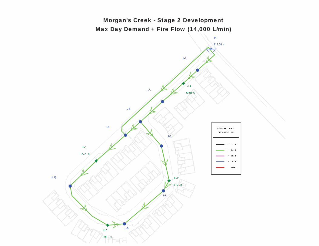
Max Day Demand + Fire Flow (14,000 L/min)Morgan's Creek - Stage 2 Development
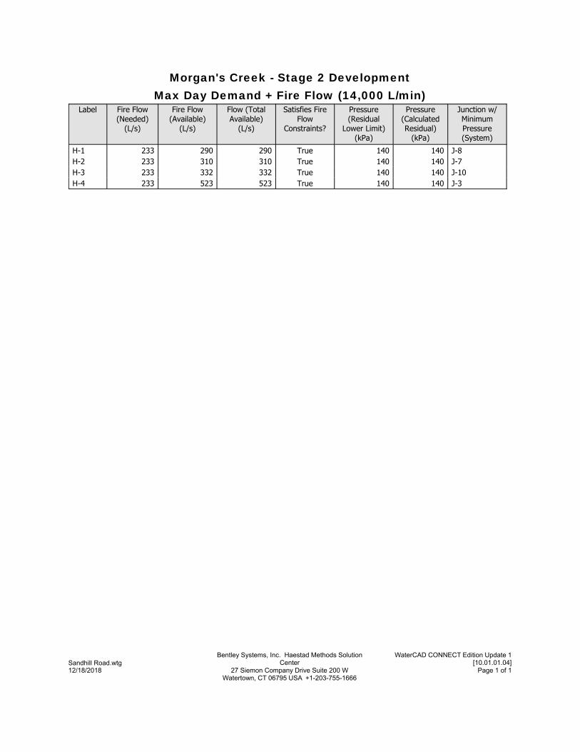
Max Day Demand + Fire Flow (14,000 L/min)Morgan's Creek - Stage 2 Development
Junction w/ Minimum Pressure (System)
Pressure (Calculated Residual)
(kPa)
Pressure (Residual
Lower Limit)(kPa)
Satisfies Fire Flow
Constraints?
Flow (Total Available)
(L/s)
Fire Flow (Available)
(L/s)
Fire Flow (Needed)
(L/s)
Label
J-8140140True290290233H-1J-7140140True310310233H-2J-10140140True332332233H-3J-3140140True523523233H-4
Page 1 of 127 Siemon Company Drive Suite 200 W Watertown, CT 06795 USA +1-203-755-1666
12/18/2018
WaterCAD CONNECT Edition Update 1[10.01.01.04]
Bentley Systems, Inc. Haestad Methods Solution CenterSandhill Road.wtg

Simulation Results – High Pressure Check
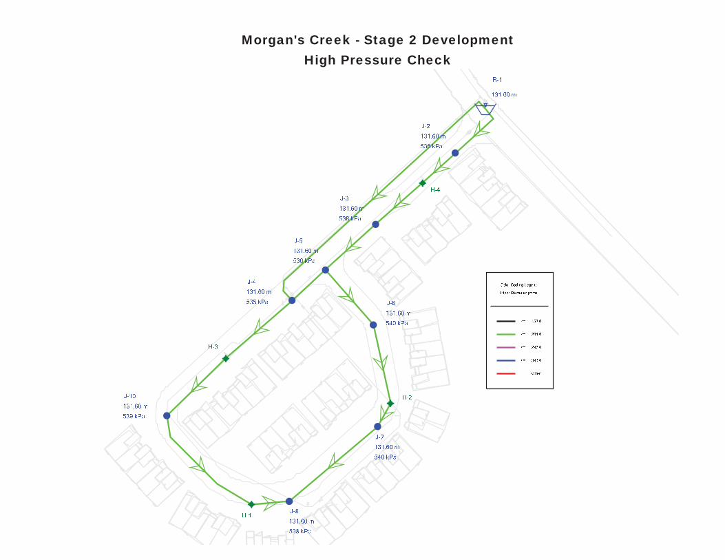
High Pressure CheckMorgan's Creek - Stage 2 Development
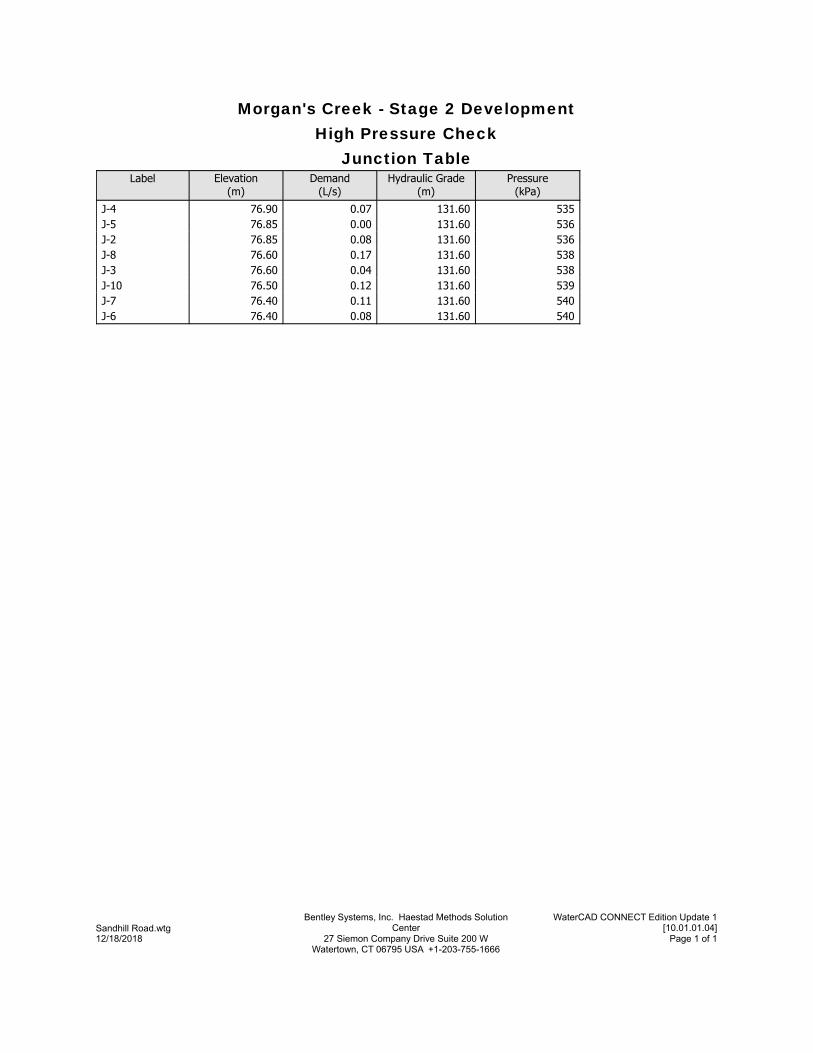
Junction TableHigh Pressure Check
Morgan's Creek - Stage 2 Development
Pressure(kPa)
Hydraulic Grade(m)
Demand(L/s)
Elevation(m)
Label
535131.600.0776.90J-4536131.600.0076.85J-5536131.600.0876.85J-2538131.600.1776.60J-8538131.600.0476.60J-3539131.600.1276.50J-10540131.600.1176.40J-7540131.600.0876.40J-6
Page 1 of 127 Siemon Company Drive Suite 200 W Watertown, CT 06795 USA +1-203-755-1666
12/18/2018
WaterCAD CONNECT Edition Update 1[10.01.01.04]
Bentley Systems, Inc. Haestad Methods Solution CenterSandhill Road.wtg
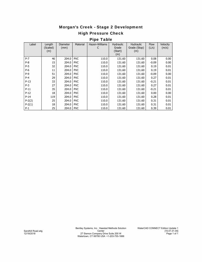
Pipe TableHigh Pressure Check
Morgan's Creek - Stage 2 Development
Velocity(m/s)
Flow(L/s)
Hydraulic Grade (Stop)
(m)
Hydraulic Grade (Start)
(m)
Hazen-Williams C
MaterialDiameter(mm)
Length (Scaled)
(m)
Label
0.000.08131.60131.60110.0PVC204.046P-70.00-0.09131.60131.60110.0PVC204.015P-80.010.19131.60131.60110.0PVC204.032P-50.010.19131.60131.60110.0PVC204.011P-60.00-0.09131.60131.60110.0PVC204.051P-90.010.27131.60131.60110.0PVC204.029P-40.01-0.21131.60131.60110.0PVC204.033P-130.010.27131.60131.60110.0PVC204.027P-30.01-0.21131.60131.60110.0PVC204.035P-110.000.00131.60131.60110.0PVC204.018P-120.010.28131.60131.60110.0PVC204.0119P-140.010.31131.60131.60110.0PVC204.025P-2(2)0.010.31131.60131.60110.0PVC204.018P-2(1)0.010.39131.60131.60110.0PVC204.025P-1
Page 1 of 127 Siemon Company Drive Suite 200 W Watertown, CT 06795 USA +1-203-755-1666
12/18/2018
WaterCAD CONNECT Edition Update 1[10.01.01.04]
Bentley Systems, Inc. Haestad Methods Solution CenterSandhill Road.wtg

Appendix ‘C’ - Sanitary

IBI Sanitary Drainage Area Plan Sandhill Road
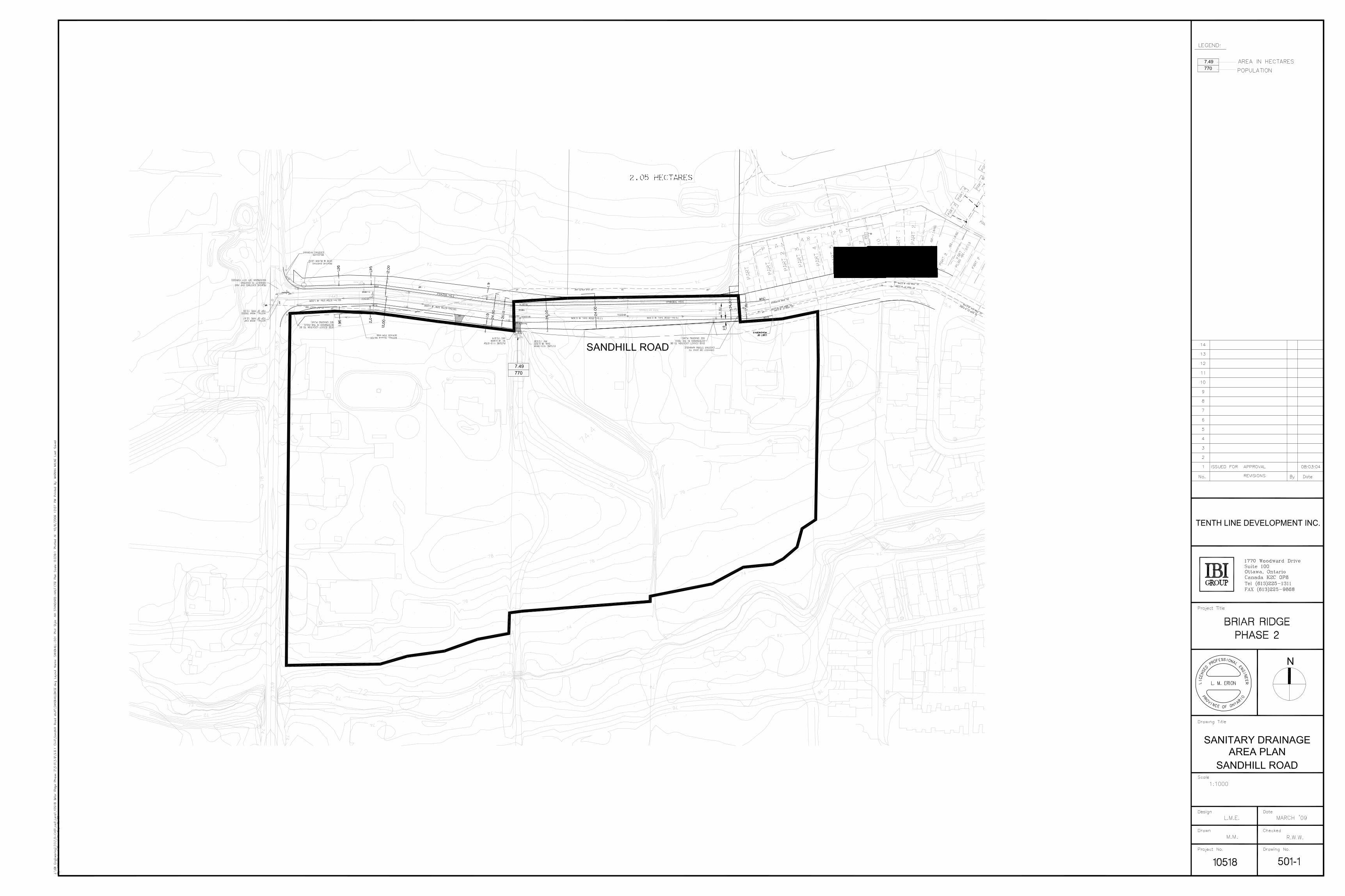

IBI Sanitary Design Sheet
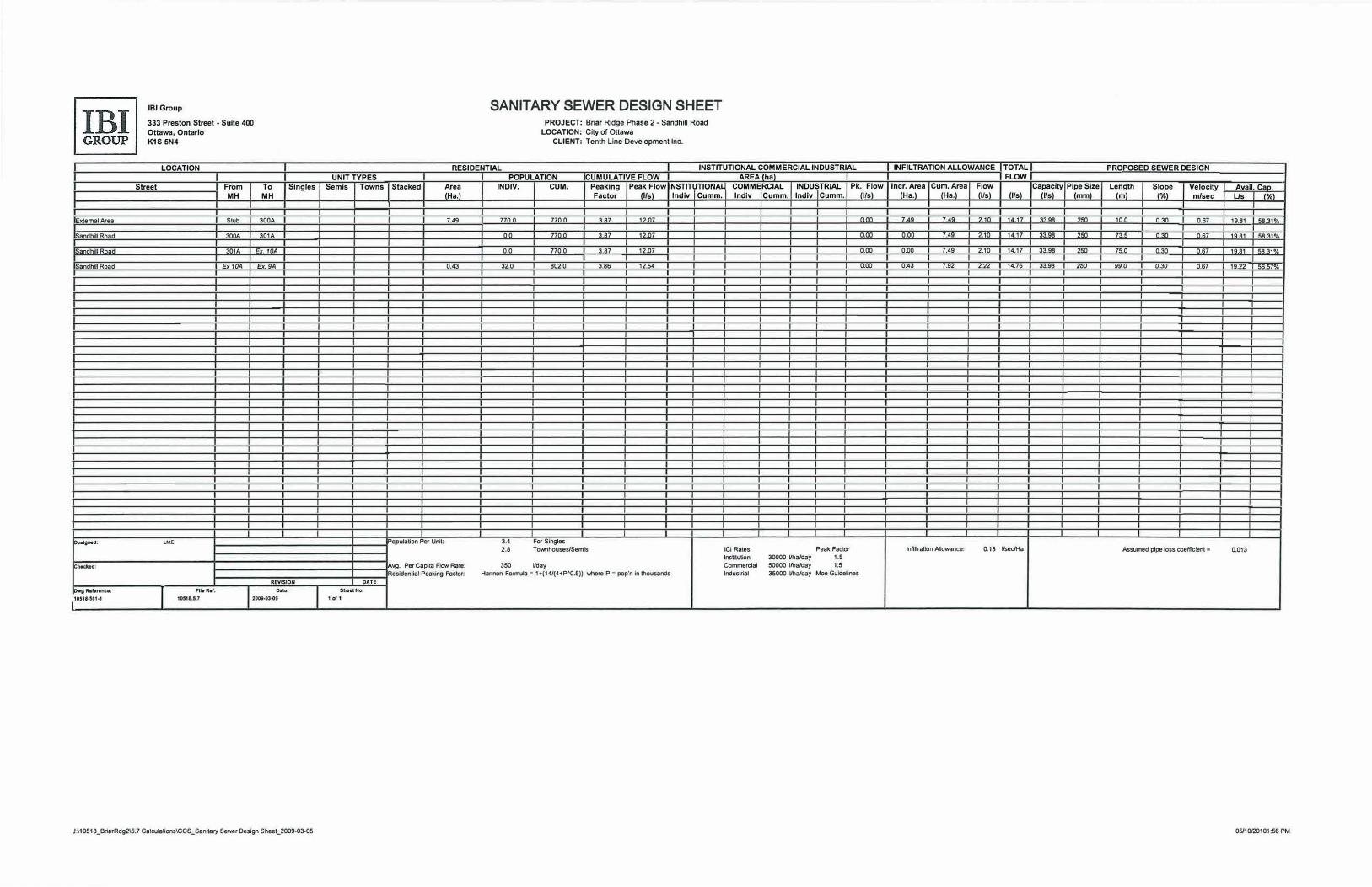
EJ<temal Area
Sandhill Road
Sandhill Road
Sandhm Road
Ooalgned:
ChllckHI:
Dwg R•ferenu:
110514.501.1
IBI Group
333 Preston Street • Suite 400 Ottawa, Ontario K1S 5N4
LOCATION
Street From MH
Stub
300A
301A
Ex10A
LME
FIie Ref:
To Singles MH
300A
301A
Ex.10A
Ex. 9A
REVISION
Date:
I 10518.5.7 2009.03.09
J:\10518_BrierRdg215.7 Calculations\CCS_Sanilary Sewer Design Sheet_2009-03-05
UNIT TYPES Semis Towns
DATE
Sheet No.
1 ol 1
SANITARY SEWER DESIGN SHEET
PROJECT: Briar Ridge Phase 2 - Sandhill Road LOCATION: City of Ottawa
CLIENT: Tenth Line Development Inc.
RESIDENTIAL INSTITUTIONAL COMMERCIAL INDUSTRIAL POPULATION CUMULATIVE FLOW AREA(hal
Stacked Area INDIV. CUM. Peaking Peak Flow INSTITUTIONAL COMMERCIAL INDUSTRIAL Pk. Flow (Ha.) Factor (1/s) lndiv Cumm. lndiv Cumm. lndlv Cumm. (Ifs)
7.49 770.0 770.0 3.87 12.07 0.00
0.0 770.0 3.87 12.07 0.00
0.0 770.0 3.87 12.07 0.00
0.43 32.0 802.0 3.86 12.54 0.00
Population Per Unit: 3.4 For Singles 2.8 Townhouses/Semis ICI Rales Peak Factor
lnstnulion 30000 Vha/day 1.5
Avg. Per Capila Flow Rale: 350 Vday Commercial 50000 Vha/day 1.5
Residential Peaking Factor: Hannon Formula - 1 +(14/(4+P"0.5)) v.toere P - pop'n in thousands Industrial 35000 Vha/day Moe Guidelines
INFILTRATION ALLOWANCE TOTAL PROPOSED SEWER DESIGN FLOW
Iner. Area Cum.Area Flow Capacity Pipe Size Length Slope Velocity Avail. Cap. (Ha.) (Ha.) (Ifs) (Ifs) (Us) (mm) (ml (%) m/sec Us (%)
7.49 7.49 2.10 14.17 33.98 250 10.0 0.30 0.67 19.81 58.31%
0.00 7.49 2.10 14.17 33.98 250 73.5 0.30 0.67 19.81 58.31%
0.00 7.49 2.10 14.17 33.98 250 75.0 0.30 0.67 19.81 58.31%
0.43 7.92 222 14.76 33.98 250 99.0 0.30 0.67 19.22 56.57%
lnfiltralion Allowance: 0.13 Vsec/Ha Assumed pipe loss coefficient= 0.013
05/10/20101:56 PM

Appendix ‘D’ - Storm

IBI Storm Drainage Area Plan Sandhill Road
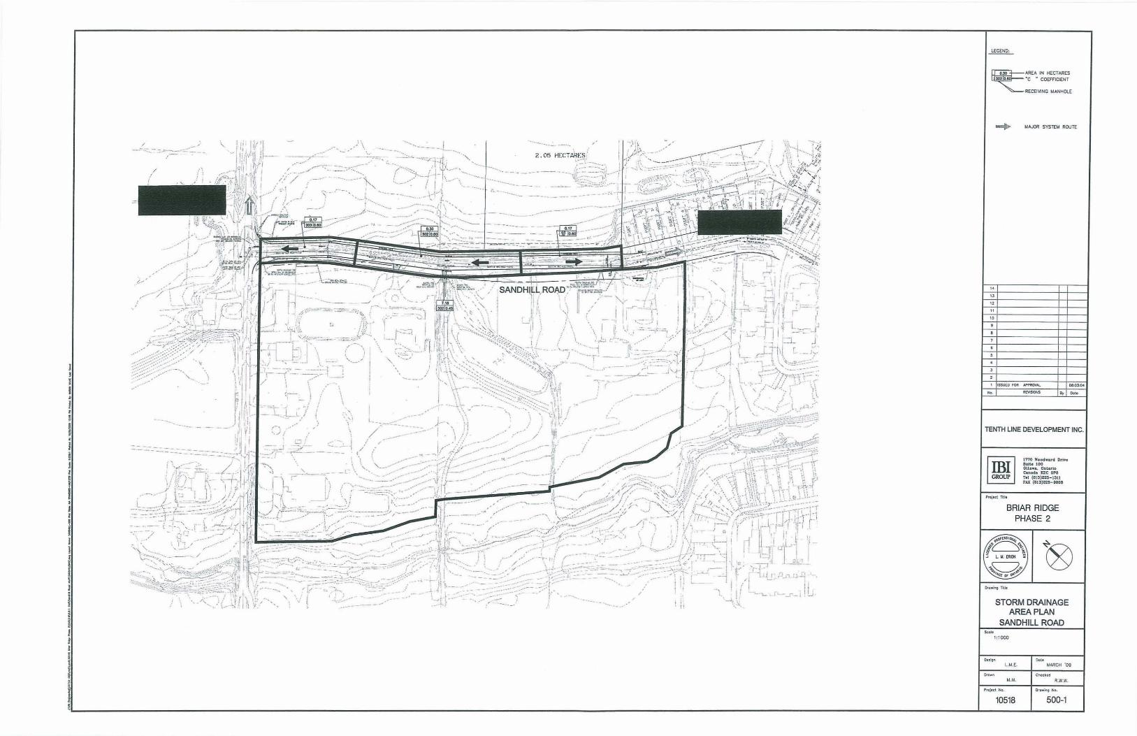
I l I I • I • l
i j I
I I
I I
i I I
I I
I j i I I I
I
... .- ..
//"/
" ,
.. ...•
," --7'"-
. ... .".i :'
-' .~.
2=---~-~
, ,
.}\
/ <,
,
... __ ....
--'
/ , .-.--."....--
'--_ .......... ," .....
- - - -- ---, "-"':'
---,--- - - ---,",,,,",
/
~30 AREA IN HECTARES
lO2 'c • CO(ffICI(NT
RECEIVING MANHOlE
" " " "
'.,
t.lA,.o()R SYSTEt.I ROUTE
TENTH LINE DEVELOPMENT INC.
1''n0 Woodwor<l Dri'oe Sullo 100 Olta .... OatlJ'lo !;<on. d. IG!C OPB Tel (813)225-1311 FAX (813)22$-0863
BRIAR RIDGE PHASE 2
STORM DRAINAGE AREA PLAN
SANDHILL ROAD .~
1:1000
UtE. ~ ..
MARCH '09
Choc'.d
R.W.W.
l:L-________________________________________ ~~~ 500-1 10518

IBI Storm Design Sheet
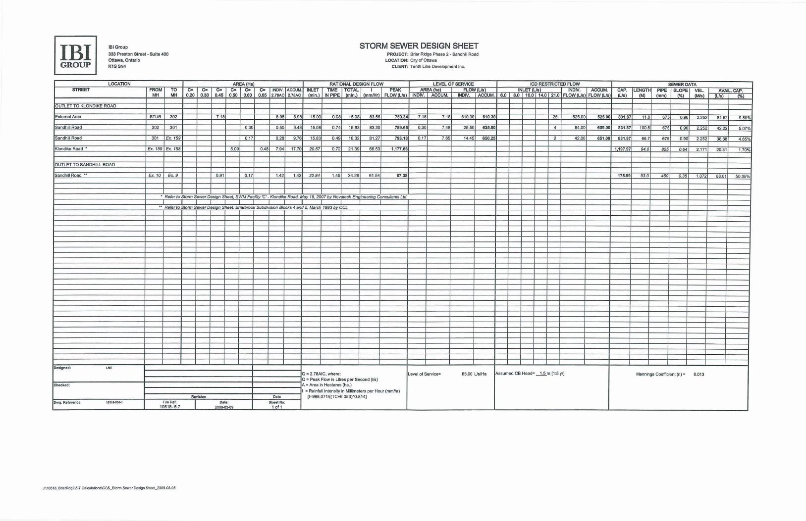
IBI IBI Group STORM SEWER DESIGN SHEET 333 Preston Street· Suile 400 PROJECT: Briar Ridge Phase 2 - Sandhl l Road
ottawa, OntarIo LOCATION: City of Ottawa GROUP K1$ 5N4 CLIENT: Tenth line Development Inc.
LOCATION AREA. (Ha) RATIONAL DESIGN FLOW LEVEL OF SERVICE ICD RESTRICTeD FLOW SEWER DATA STREET FROM TO Co c- C= c- Co Co INOIV. ACCUM. INLET TIME TOTAL I PEAK MEA • FLOW s INLET • INDIV. A~~~ ~i LE~~TH PIPE SLOPE VEL. AVAIL. CAP.
MH MH 0.20 0.30 0.45 0.50 0.60 0.65 2.7BAC 2.78AC (min .) IN PIPE (min.) (mmIH' FLOW(Us) INOIV. ACCUM. INOW. ACCUM. 6.0 8.0 10.0 14.0 21 .0 FLOW (Us FLOW lis (mm) (%) (MI.) • (%)
OUTLET TO KLONDIKE ROAD
External Area STUB 302 7.18 8.98 8.98 15.00 0.08 15.08 83.56 750.34 7.18 7.18 610.30 610.30 25 525.00 525.00 831 .87 11 .0 675 0.90 2.252 81.52 9.80%
Sandhill Road 302 301 0.30 0.50 9.48 15.08 0.74 15.83 83.30 789.65 0.30 7.48 25.50 635.80 4 84 .00 609.00 831.87 100.5 675 0.90 2.252 42.22 5.07%
Sandhill Road 301 Ex. 159 0.17 0.28 9 .76 15.83 0.49 16.32 81 .27 793.18 0 .17 7.65 14.45 650.25 2 42.00 651.00 831.87 66.7 675 0.90 2.252 38.68 4 .65%
Klondike Road • Ex. 159 Ex. 158 5.09 0.48 7.94 17.70 20.67 0.72 21 .39 66.53 1,177.66 1197.97 94.0 825 0.64 2.171 20.31 1.70%
OUTLET TO SANDHILL ROAD
SandhiU Road •• Ex. lO Ex. 9 0.91 0.17 1.42 1.42 22.84 1.45 24.29 61 .54 87.38 175.99 93.0 450 0.35 1.072 68.61 50.35%
• Refer to Storm Sewer Design Sheet, SWM Facility 'C' - Klondike Road, May 18. 2007 by Novatech Engineering ConsuftBnts Ltd .
•• Refer to Storm Sewer Des ' n Sheet. Briarbrook Subdivision Blocks 4 and 5, March 1993 b CCL
Designed: '"' a: 2.78AIC. where: Level of Service: 85.00 UslHa Assumed CB Head: ~m [1 :5 yr) Mannings CoeffICient (n)- 0.013 a: Peak Flow in Litres per Second (Us)
Cheeked: A " Area in Hectares (ha.)
I " Raintan Intensity in Millimeters per Hour (mmnu) Revision Dale [1"998.071 I«(TC+6.053)"'O.B14)
Dwg. Refere"ce: 10511-500.1 File Ref: Dele: Sheel No: 1051 8· 5.7 2009-(13-()9 10f 1
J :ll 0S18_ BrierRdg2\5.7 CaICl,llations\CCS_SlollT1 Sewer Design She eC2009"()3-OS

Stormwater Management Calculations Spreadsheet
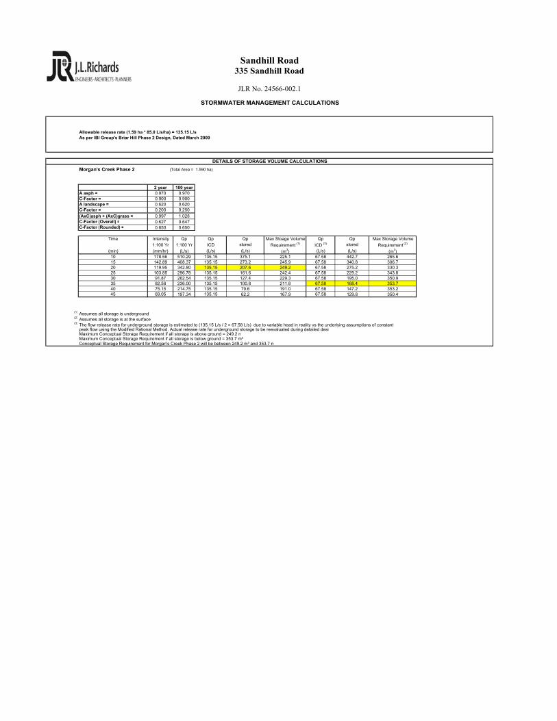
Morgan's Creek Phase 2 (Total Area = 1.590 ha)
2 year 100 yearA asph = 0.970 0.970C-Factor = 0.900 0.900A landscape = 0.620 0.620C-Factor = 0.200 0.250
(AxC)asph + (AxC)grass = 0.997 1.028C-Factor (Overall) = 0.627 0.647C-Factor (Rounded) = 0.650 0.650
Time Intensity Qp Qp Qp Max Stoage Volume Qp Qp Max Storage Volume
1:100 Yr 1:100 Yr ICD stored Requirement (1) ICD (3) stored Requirement (2)
(min) (mm/hr) (L/s) (L/s) (L/s) (m3) (L/s) (L/s) (m3)10 178.56 510.29 135.15 375.1 225.1 67.58 442.7 265.615 142.89 408.37 135.15 273.2 245.9 67.58 340.8 306.720 119.95 342.80 135.15 207.6 249.2 67.58 275.2 330.325 103.85 296.78 135.15 161.6 242.4 67.58 229.2 343.830 91.87 262.54 135.15 127.4 229.3 67.58 195.0 350.935 82.58 236.00 135.15 100.8 211.8 67.58 168.4 353.740 75.15 214.75 135.15 79.6 191.0 67.58 147.2 353.245 69.05 197.34 135.15 62.2 167.9 67.58 129.8 350.4
(1) Assumes all storage is underground(2) Assumes all storage is at the surface(3)
Maximum Conceptual Storage Requirement if all storage is above ground = 249.2 mMaximum Conceptual Storage Requirement if all storage is below ground = 353.7 m³Conceptual Storage Requirement for Morgan's Creek Phase 2 will be between 249.2 m³ and 353.7 m
Allowable release rate (1.59 ha * 85.0 L/s/ha) = 135.15 L/sAs per IBI Group's Briar Hill Phase 2 Design, Dated March 2009
Sandhill Road335 Sandhill Road
JLR No. 24566-002.1
STORMWATER MANAGEMENT CALCULATIONS
DETAILS OF STORAGE VOLUME CALCULATIONS
The flow release rate for underground storage is estimated to (135.15 L/s / 2 = 67.58 L/s) due to variable head in reality vs the underlying assumptions of constantpeak flow using the Modified Rational Method. Actual release rate for underground storage to be reevaluated during detailed desig

Appendix ‘E’ – Preliminary Engineering Drawings