Embed Size (px)
Citation preview

Proceedings of the International Conference on Mechanical Engineering and Renewable Energy 2017
(ICMERE2017) 18 – 20 December, 2017, Chittagong, Bangladesh
ICMERE2017-PI-254
© ICMERE2017
1. INTRODUCTION In the past few years, researchers have grown an
interest in nano science and technology. Using structure
at micron and nano level is the key to the development of
electronic devices and elements of micro/nano
electromechanical system (MEMS/NEMS). For
scientific and engineering purposes it is important to
study and understand the mechanical properties. In recent
years, great interest has been shown on nanowires and
other one-dimensional systems due to their potential in
different types of applications. Different types of
nanowires have been developed using chemical routes
such as laser assisted catalytic growth. The mechanical
strength of nanowires is necessary to maintain the
structural integrity of the systems.
Over the last past few years’ computer simulation
technique was developed to determine the mechanical
properties. Simulations using molecular dynamics
method are capable of unveiling some processes to
explain the fundamental mechanism of dislocation
formation, plastic region and breaking of nanomaterial
under stress.
Recently many researchers have studied the tensile
deformation of nanowires under uniaxial tension using
numerical methods such as molecular dynamics.
Komandari et al. [1,2] used Morse potential for modeling
BCC and FCC nanowires. They found that the two body
potentials could not predict the tensile behavior of BCC
metals accurately. Park et al. [3, 4] simulated the tensile
test for FCC nanowires with different crystallographic
orientations. Recently Wu [5, 6] studied the mechanical
properties of the copper nanowire at different
temperatures, sizes and strain rates. Golovnev [7]
developed more results on copper nanowires. Lin Yuan et
al. [8] studied aluminum nanocrystal under the uniaxial
tension at different temperatures. Branico and Rino [9]
investigated the failure mechanism of Ni nanowires.
Wena et al. [10] employed the molecular dynamics
simulation with quantum corrected suttenchen type many
body potential for Ni nanowire at room temperature.
Further studies on the mechanical behavior of
nanowires with various loading, Parinello and Rahman
[11] introduced a new Lagrangian formulation to perform
MD simulations on systems under external stress. Using
this method, they applied uniaxial stress to an FCC cubic
lattice (Ni) with periodic boundary conditions at 350 𝐾. Under uniaxial compression, they suggested a
transformation in the crystal structure from FCC to HCP.
The maximum tensile strength under uniaxial tension
was reported to be 11 × 1010 dyn/cm^2 . Kitamura et
al[12] conducted atomic simulations of tension on a
nanoscopic wire, film, and bulk of a Ni lattice without
defects. To investigate the effect of constraint of
transverse deformation on the fracture process,
simulations for the bulk were conducted under two
conditions: free transverse stress condition and fully
constrained condition. During the fracture process, the
wire and the film were reported to exhibit multiple slip
resulting in the neck formation after a strain of 1.0.
Concentrated shear deformation with the localization of
slip in the necked region was reported to result in ductile
fracture. However, with the bulk specimen, they reported
SIZE DEPENDENT STUDY OF MECHANICAL PROPERTIES OF COBALT THIN
FILMS UNDER UNIAXIAL AND BIAXIAL TENSION
Shahriar Nahian1, Arefin Mustafa Anik2, Tawfiqur Rakib3, Satyajit Mojumder 4
1-4Department of Mechanical Engineering, Bangladesh University of Engineering and Technology
Dhaka-1000, Bangladesh
[email protected]*, [email protected], [email protected],
Abstract- The mechanical properties of Cobalt thin film have been an important issue due to its application
as magnetic films in electronics and biomedical field. Being subjected to numerous applications, its
mechanical properties remain a key issue. In this paper, molecular dynamics simulations are conducted to
find the mechanical properties of Cobalt (Co) thin film. Embedded Atom Method (EAM) potential is
employed to define the atomic interactions between Co atoms.The present study shows the mechanical
properties and failure mechanism of Cobalt thin films under uniaxial and biaxial tension as its thickness (t)
varies in the range of t=2~10nm.The result shows that the ultimate tensile strength decreases with the
increase of thickness of the thin films. Finally, failure mechanisms are shown in consecutive atomic images.
Keywords: Molecular Dynamics, Tensile Strength, Stress Concentration, Thin Film, Atomic Potential
© ICMERE2017
the absence of necking by slip even at a strain of 1.0. The
transformation was reported to be induced by the tensile
strain. In the case of tension experiments with free
transverse stress condition, i.e. without the constraint of
transverse deformation, yielding was reported to be
brought about by the crystallographic slip on the (1 1 1)
planes at a strain of ∼0:1. The yield stress in tension was
found to be 15–20 GPa and very little difference in
strength was reported between the wire, the film, and the
bulk. Multiple slip even after yielding of the crystal and
significant plastic deformation were reported to cause the
ductile shear fracture. In the simulations with constraint
of transverse deformation, the yield stress was reported
to reach 40 GPa. No plastic strain was generated. This is
attributed to the restriction of dislocation glide. Cleavage
cracks were observed and found to bring about brittle
fracture and hence a change in the fracture mode.
In this investigation, molecular dynamic simulation
was carried out to study the effect on the mechanical
properties of cobalt thin film under uniaxial and biaxial
stress. The effect on the mechanical properties due to the
change in cross section was also studied.
2. METHODOLOGY Three-dimensional cobalt nanocrystalline sheets with
various thicknesses between 2 and 10 nm were created by
a computer code using LAMMPS with periodic boundary
conditions in the three primary axes. The other two
dimensions of nanosheets were kept 20 nm. The number
of atoms in each sample varied from 74,000 to 362,640
according to film thickness. To perform molecular
dynamics simulations using the LAMMPS code [13],
EAM (embedded-atom method) potential was employed
suggested by G. P. Purja Punand and Y. Mishin [14].
In the EAM formalism, the total energy of a collection
of atoms is represented by,
𝐸 =1
2∑ 𝜙(𝑟)𝑖,𝑗 +∑ 𝐹(𝜌�̅�)𝑖 , (1)
where 𝜙(𝑟𝑖𝑗) is a pair-interaction potential as a function
of distance 𝑟 between atoms 𝑖 and 𝑗𝐹(�̅�𝑖) is the
embedding energy as a function of the host electron
density �̅�𝑖 on atom 𝑖. The electron density is the sum of
atomic electron densities created at 𝑖 by all other atoms
of the system.
𝜌 = ∑ 𝜌(𝑟𝑖 𝑘) , (2)𝑘≠𝑖
The pair interactions are described by the generalized
Lennard-Jones-type function.
𝜑(𝑟) = 𝜓 (𝑟−𝑟𝑐
ℎ) [
𝑉𝑜
𝑏2−𝑏1(
𝑏2
(𝑟 𝑟1⁄ )𝑏1−
𝑏1
(𝑟 𝑟1⁄ )𝑏2) + 𝛿, (3)
Equilibration simulations at NVE ensemble were
performed for 50ps. NVE simulations were followed by
a pressure equilibration for 150ps using NPT ensemble at
atmospheric pressure. NVT simulations were done at
300K temperature for 10ps. An MD time step of 0.001ps
was used for all the simulations considered in this study.
The loading rate and temperature were kept constant at
109s-1 and 300K respectively. The OVITO code [15] was
employed to visualize and analyze the simulation results.
Structural characterization of the simulated systems was
performed using adaptive common neighbor analysis
[16]. In order to visualize the structure of the simulated
systems, atoms were colored according to their local
structure order. The atoms with perfect HCP structure are
shown as red, while those with perfect FCC structure are
shown as green.
Fig. 1: An initial configuration of Co thin film with size
of 20×20×10 nm.
3. RESULT AND DISCUSSION
3.1 Uniaxial Loading The generated results of the molecular dynamics
simulations are presented. The primary purpose of this
work is to establish a relationship between film thickness
and tensile strength. To elucidate that relationship, the
stress vs. strain graph is presented in Fig 1.The figure
shows two different types of responses. The stress either
produce double peak meaning strain hardening or
increasing, oscillating and then decreases. The stress
increases linearly with strain up to a strain of 10%.
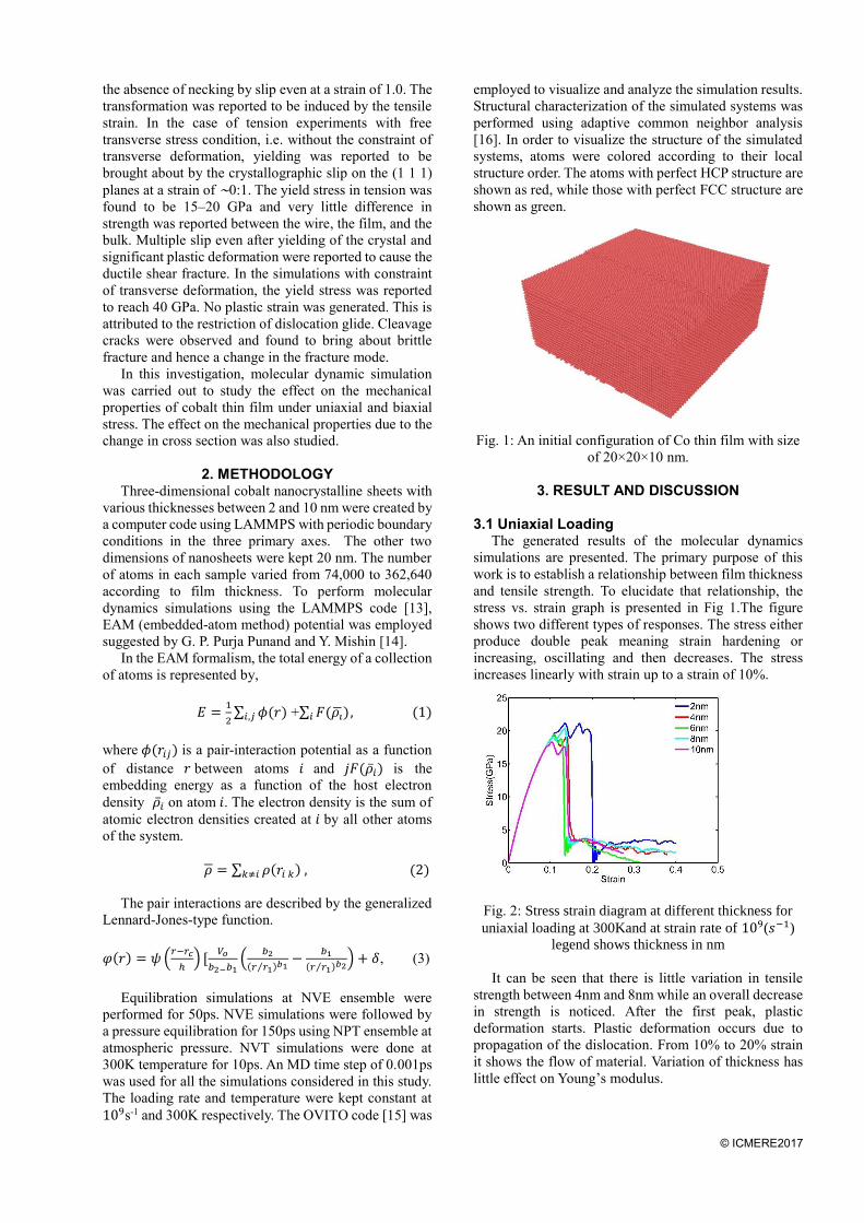
Fig. 2: Stress strain diagram at different thickness for
uniaxial loading at 300Kand at strain rate of 109(𝑠−1)
legend shows thickness in nm
It can be seen that there is little variation in tensile
strength between 4nm and 8nm while an overall decrease
in strength is noticed. After the first peak, plastic
deformation starts. Plastic deformation occurs due to
propagation of the dislocation. From 10% to 20% strain
it shows the flow of material. Variation of thickness has
little effect on Young’s modulus.
© ICMERE2017
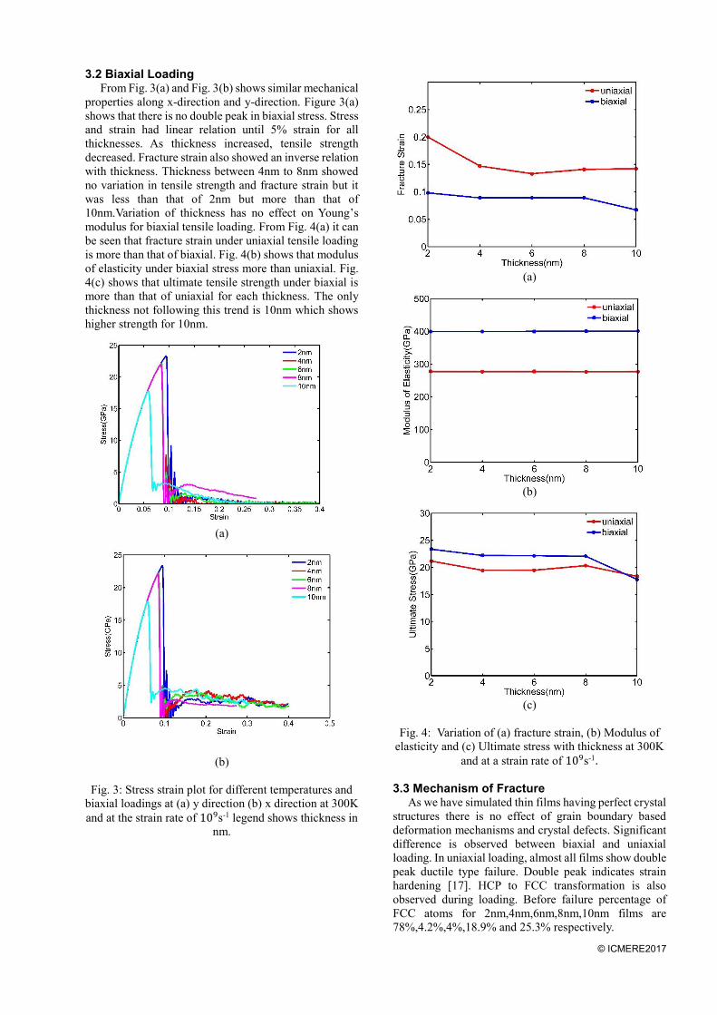
3.2 Biaxial Loading From Fig. 3(a) and Fig. 3(b) shows similar mechanical
properties along x-direction and y-direction. Figure 3(a)
shows that there is no double peak in biaxial stress. Stress
and strain had linear relation until 5% strain for all
thicknesses. As thickness increased, tensile strength
decreased. Fracture strain also showed an inverse relation
with thickness. Thickness between 4nm to 8nm showed
no variation in tensile strength and fracture strain but it
was less than that of 2nm but more than that of
10nm.Variation of thickness has no effect on Young’s
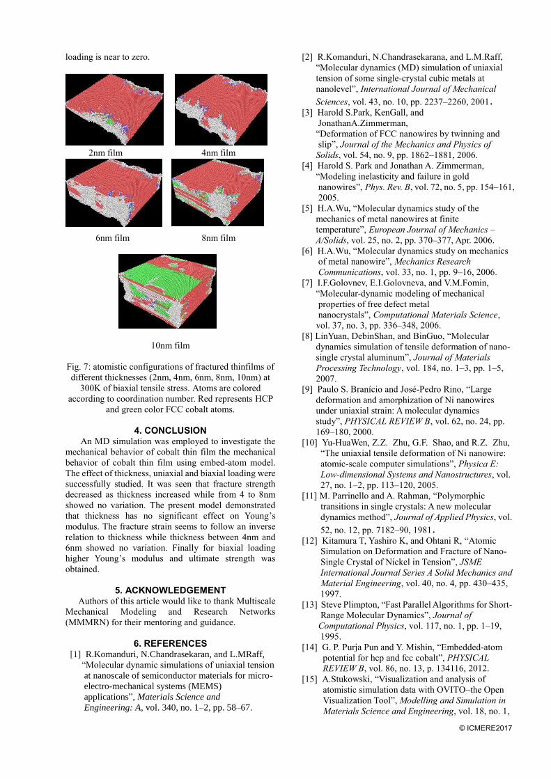
modulus for biaxial tensile loading. From Fig. 4(a) it can
be seen that fracture strain under uniaxial tensile loading
is more than that of biaxial. Fig. 4(b) shows that modulus
of elasticity under biaxial stress more than uniaxial. Fig.
4(c) shows that ultimate tensile strength under biaxial is
more than that of uniaxial for each thickness. The only
thickness not following this trend is 10nm which shows
higher strength for 10nm.
(a)
(b)
Fig. 3: Stress strain plot for different temperatures and
biaxial loadings at (a) y direction (b) x direction at 300K
and at the strain rate of 109s-1 legend shows thickness in
nm.
(a)
(b)
(c)
Fig. 4: Variation of (a) fracture strain, (b) Modulus of
elasticity and (c) Ultimate stress with thickness at 300K
and at a strain rate of 109s-1.
3.3 Mechanism of Fracture As we have simulated thin films having perfect crystal
structures there is no effect of grain boundary based
deformation mechanisms and crystal defects. Significant
difference is observed between biaxial and uniaxial
loading. In uniaxial loading, almost all films show double
peak ductile type failure. Double peak indicates strain
hardening [17]. HCP to FCC transformation is also
observed during loading. Before failure percentage of
FCC atoms for 2nm,4nm,6nm,8nm,10nm films are
78%,4.2%,4%,18.9% and 25.3% respectively.

© ICMERE2017
In Fig. 4(a) the failure mechanism for thin film of
thickness 2nm is shown. The fracture pattern is observed
to follow typical behavior for perfect crystal. Fracture
initiates via formation of small fissure in the structure due
to the stress concentration at the strain value of 1.95 %.
Fig. 4(a) and Fig. 4(b) shows the flow of materials at
strain value of 10% to 20% for 2nm thickness. 2nm film
is slightly different from other films and hence studied
extensively. Stress concentration and movement of atoms
with displacement vectors are shown for different values
of strains.
12% strain 19% strain 19.7% strain
(a)
19.25% strain 19.66% strain 19.80% strain
(b)
Fig. 4: (a) Atomistic configurations of thin film of 2nm
thickness at 300K at different stages (12%, 19%, 19.7%
strain) of uniaxial tensile stress. Atoms are colored
according to coordination number. Red represents HCP
and green color FCC cobalt atoms (b) Displacement
vectors of same thin film atoms at 300K at different
stages (19.25% 19.66% 19.8%) for uniaxial tensile
stress. Displacement vectors are shown in green color.
In Fig. 5 images of crystal when failure occurs is
shown. Though crack initiation spot is different in
different cases but considering periodic boundary
condition we can say propagation is same for all films of
different thicknesses in uniaxial loading.
Variation of values of ultimate stress and fracture
strain is seen in uniaxial loading with film size. Thin
films of 2nm and 10nm show the maximum and
minimum values of ultimate stress and fracture strain
respectively. Actually, for small sized nanosheets
dislocations are generated and propagated within small
dimensions but the large size nanosheets have enough
space for dislocation propagation.
4nm to 10nm thin films shows a double peak in the
plastic region and before fracture they show deformation
twinning. HCP structure most likely to form deformation
twin when they are strained [18]. In 4 nm wire (shown in
Fig. 6), generated twins are responsible for crack
initiation. The movement of dislocation is towards twin
boundary which causes propagation of the crack.
Multiple twin structure is formed at about 11.5%.
2nm film 4nm film
6nm film 8nm film
10nm film
Fig. 5: Atomistic configurations of fractured thin films of
different thicknesses (2nm, 4nm, 6nm, 8nm, 10nm) at
300K of uniaxial tensile stress. Atoms are colored
according to coordination number. Red represents HCP
and green color FCC cobalt atoms.
13.30% strain
14.05% strain
14.12% strain
14.20% strain
Fig. 6: Atomistic configurations of thin film of 4nm
thickness at 300K at different stages (13.30%, 14.05%,
14.12%, 14.20% strain) of uniaxial tensile stress atoms
are colored according to coordination number red
represents HCP and green color FCC cobalt atoms.
In the case of biaxial loading, the failure criteria is
totally different. Stress vs. strain plot Fig.3 for biaxial
loading indicates brittle type behavior. Plots for all
thicknesses shows single peak and sudden drop in value
of stress. HCP to FCC transformation is not seen in
biaxial loading. The percentage of FCC atoms before
© ICMERE2017
loading is near to zero.
2nm film 4nm film
6nm film 8nm film
10nm film
Fig. 7: atomistic configurations of fractured thinfilms of
different thicknesses (2nm, 4nm, 6nm, 8nm, 10nm) at
300K of biaxial tensile stress. Atoms are colored
according to coordination number. Red represents HCP
and green color FCC cobalt atoms.
4. CONCLUSION
An MD simulation was employed to investigate the
mechanical behavior of cobalt thin film the mechanical
behavior of cobalt thin film using embed-atom model.
The effect of thickness, uniaxial and biaxial loading were
successfully studied. It was seen that fracture strength
decreased as thickness increased while from 4 to 8nm
showed no variation. The present model demonstrated
that thickness has no significant effect on Young’s
modulus. The fracture strain seems to follow an inverse
relation to thickness while thickness between 4nm and
6nm showed no variation. Finally for biaxial loading
higher Young’s modulus and ultimate strength was
obtained.
5. ACKNOWLEDGEMENT
Authors of this article would like to thank Multiscale
Mechanical Modeling and Research Networks
(MMMRN) for their mentoring and guidance.
6. REFERENCES [1] R.Komanduri, N.Chandrasekaran, and L.MRaff,
“Molecular dynamic simulations of uniaxial tension
at nanoscale of semiconductor materials for micro-
electro-mechanical systems (MEMS)
applications”, Materials Science and
Engineering: A, vol. 340, no. 1–2, pp. 58–67.
[2] R.Komanduri, N.Chandrasekarana, and L.M.Raff,
“Molecular dynamics (MD) simulation of uniaxial
tension of some single-crystal cubic metals at
nanolevel”, International Journal of Mechanical
Sciences, vol. 43, no. 10, pp. 2237–2260, 2001. [3] Harold S.Park, KenGall, and
JonathanA.Zimmerman,
“Deformation of FCC nanowires by twinning and
slip”, Journal of the Mechanics and Physics of
Solids, vol. 54, no. 9, pp. 1862–1881, 2006.
[4] Harold S. Park and Jonathan A. Zimmerman,
“Modeling inelasticity and failure in gold
nanowires”, Phys. Rev. B, vol. 72, no. 5, pp. 154–161,
2005.
[5] H.A.Wu, “Molecular dynamics study of the
mechanics of metal nanowires at finite
temperature”, European Journal of Mechanics –
A/Solids, vol. 25, no. 2, pp. 370–377, Apr. 2006.
[6] H.A.Wu, “Molecular dynamics study on mechanics
of metal nanowire”, Mechanics Research
Communications, vol. 33, no. 1, pp. 9–16, 2006.
[7] I.F.Golovnev, E.I.Golovneva, and V.M.Fomin,
“Molecular-dynamic modeling of mechanical
properties of free defect metal
nanocrystals”, Computational Materials Science,
vol. 37, no. 3, pp. 336–348, 2006.
[8] LinYuan, DebinShan, and BinGuo, “Molecular
dynamics simulation of tensile deformation of nano-
single crystal aluminum”, Journal of Materials
Processing Technology, vol. 184, no. 1–3, pp. 1–5,
2007.
[9] Paulo S. Branício and José-Pedro Rino, “Large
deformation and amorphization of Ni nanowires
under uniaxial strain: A molecular dynamics
study”, PHYSICAL REVIEW B, vol. 62, no. 24, pp.
169–180, 2000.
[10] Yu-HuaWen, Z.Z. Zhu, G.F. Shao, and R.Z. Zhu,
“The uniaxial tensile deformation of Ni nanowire:
atomic-scale computer simulations”, Physica E:
Low-dimensional Systems and Nanostructures, vol.
27, no. 1–2, pp. 113–120, 2005.
[11] M. Parrinello and A. Rahman, “Polymorphic
transitions in single crystals: A new molecular
dynamics method”, Journal of Applied Physics, vol.
52, no. 12, pp. 7182–90, 1981. [12] Kitamura T, Yashiro K, and Ohtani R, “Atomic
Simulation on Deformation and Fracture of Nano-
Single Crystal of Nickel in Tension”, JSME
International Journal Series A Solid Mechanics and
Material Engineering, vol. 40, no. 4, pp. 430–435,
1997.
[13] Steve Plimpton, “Fast Parallel Algorithms for Short-
Range Molecular Dynamics”, Journal of
Computational Physics, vol. 117, no. 1, pp. 1–19,
1995.
[14] G. P. Purja Pun and Y. Mishin, “Embedded-atom
potential for hcp and fcc cobalt”, PHYSICAL
REVIEW B, vol. 86, no. 13, p. 134116, 2012.
[15] A.Stukowski, “Visualization and analysis of
atomistic simulation data with OVITO–the Open
Visualization Tool”, Modelling and Simulation in
Materials Science and Engineering, vol. 18, no. 1,

© ICMERE2017
p.015012, 2010.
[16] A.Stukowski, “Structure identification methods for
atomistic simulations of crystalline
materials”, Modelling and Simulation in Materials
Science and Engineering, vol. 20, no. 4, p. 045021.
[17] S.Saha, M.A.Motalab, and M.Mahboob,
“Investigation on mechanical properties of
polycrystalline W nanowire”, Computational
Materials Science, vol. 136, pp. 52–59, 2017.
[18] Steinmetz, D.R, Jäpel, T., Wietbrock, B.,
Eisenlohr,P., Gutierrez-Urrutia,I, and Saeed,
“Revealing the strain-hardening behavior of
twinning-induced plasticity steels: Theory,
simulations, experiments”, Acta Materialia, vol. 61,
no. 2, pp. 494–510,2013.
7. NOMANCLETURE
Symbol Meaning Unit
E Total Energy eV
Q
Pair interaction potential
eV
r
distance nm
rc Cutoff distance nm
V fitting parameter eV
𝛿 fitting parameter eV
F embedding energy
function
eV