Embed Size (px)
Citation preview
SK TECH CO., LTD. Page 2 of38
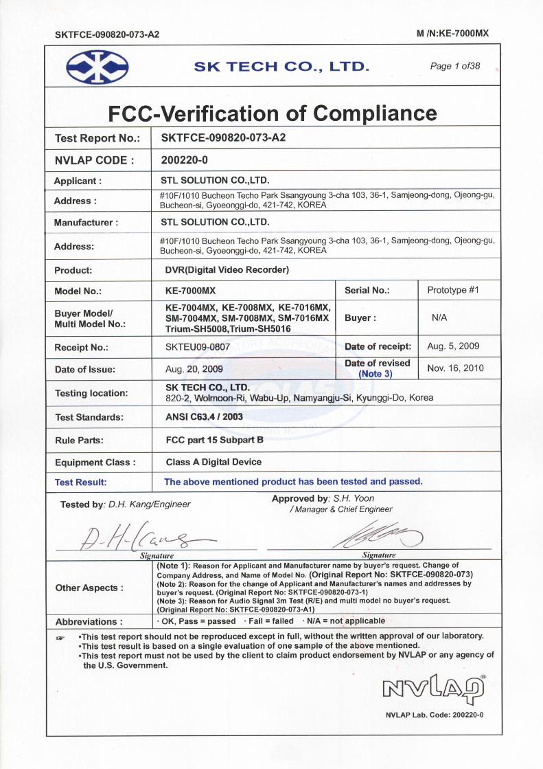
SKTFCE-090820-073-A2 M /N:KE-7000MX
》》 Contents 《《
Contents 2 List of Supplements 3 List of Tables 3 List of Photographs 3 1. General 4 2. Test Site 4
2.1 Location 4 2.2 List of Test and Measurement Instruments 5 2.3 Test Date 5 2.4 Test Environment 5
3. Summary of test results 6 4. Description of the tested samples 7
4.1 Rating and Physical Characteristics 7 4.2 Submitted Documents 8
5. Measurement Conditions 9 5.1 Modes of Operation 9 5.2 Additional Equipments 9 5.3 Type of Used Cables 10 5.4 Test Setup 11 5.5 Uncertainty 12
6. Test Results 13 6.1 Conducted Emissions 13 6.2 Radiated Emissions 17
7. Photographs of the Test Set-up 19-20 Annex1 Label 21 Annex2 Photographs of EUT 22-38
SK TECH CO., LTD. Page 3 of38
SKTFCE-090820-073-A2 M /N:KE-7000MX
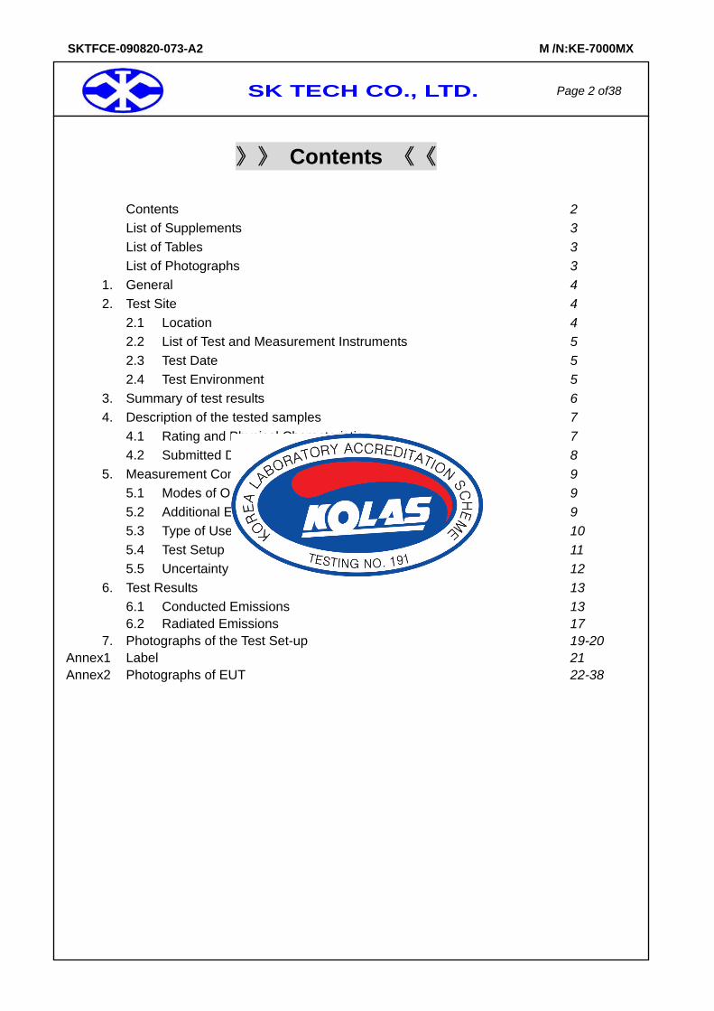
》List of Supplements Supplement 1 Test Data, conducted Disturbance 14 Supplement 2 Spectral Diagram, LINE-PE 15 Supplement 3 Spectral Diagram, NEUTRAL-PE 16
》List of Tables Table 1 List of test and measurement Equipment 5 Table 2 Test Data, Radiated Emissions 18
》List of Photographs Photograph 1 Setup for Conducted Emission 19 Photograph 2 Setup for Radiated Emission 20
SK TECH CO., LTD. Page 4 of38
SKTFCE-090820-073-A2 M /N:KE-7000MX
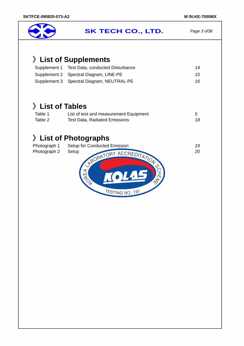
1. General
This equipment has been shown to be capable of compliance with the applicable technical standards and was tested in accordance with the measurement procedures as indicated in this report. We attest to the accuracy of data. All measurements reported herein were performed by SK Tech Co., Ltd. and were made under Chief Engineer’s supervision. We assume full responsibility for the completeness of these measurements and vouch for the qualifications of all persons taking them.
2. Test Site SK TECH Co., Ltd.
2.1 Location 820-2, Wolmoon Ri, Wabu-Up, Namyangju-Si, Kyunggi-Do, KOREA
The test site is in compliance with ISO/IEC 17025 for general requirements for the competence of testing and calibration laboratories. This laboratory is recognized as a Conformity Assessment Body(CAB) for CAB’s Designation Number: KR0007 by FCC, is accredited by NVLAP for NVLAP Lab. Code : 200220-0 and DATech for DAR-Registration No.DAT-P-076/97-02 and KOLAS for Accreditation No.:KT191.
SK TECH CO., LTD. Page 5 of38
SKTFCE-090820-073-A2 M /N:KE-7000MX
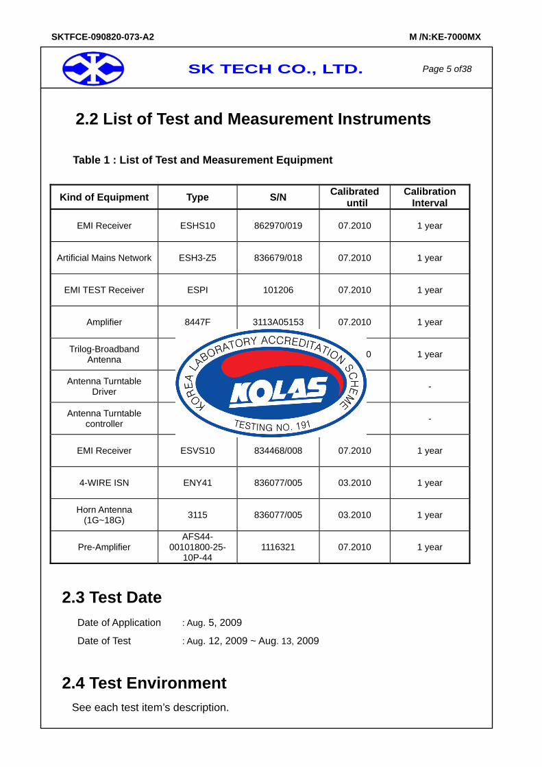
2.2 List of Test and Measurement Instruments Table 1 : List of Test and Measurement Equipment
Kind of Equipment Type S/N Calibrated until
Calibration Interval
EMI Receiver ESHS10 862970/019 07.2010 1 year
Artificial Mains Network ESH3-Z5 836679/018 07.2010 1 year
EMI TEST Receiver ESPI 101206 07.2010 1 year
Amplifier 8447F 3113A05153 07.2010 1 year
Trilog-Broadband Antenna VULB9168 9168-230 07.2010 1 year
Antenna Turntable Driver 5907 91X518 N/A -
Antenna Turntable controller 5906 91X519 N/A -
EMI Receiver ESVS10 834468/008 07.2010 1 year
4-WIRE ISN ENY41 836077/005 03.2010 1 year
Horn Antenna (1G~18G) 3115 836077/005 03.2010 1 year
Pre-Amplifier AFS44-
00101800-25-10P-44
1116321 07.2010 1 year
2.3 Test Date Date of Application : Aug. 5, 2009
Date of Test : Aug. 12, 2009 ~ Aug. 13, 2009
2.4 Test Environment See each test item’s description.
SK TECH CO., LTD. Page 6 of38
SKTFCE-090820-073-A2 M /N:KE-7000MX
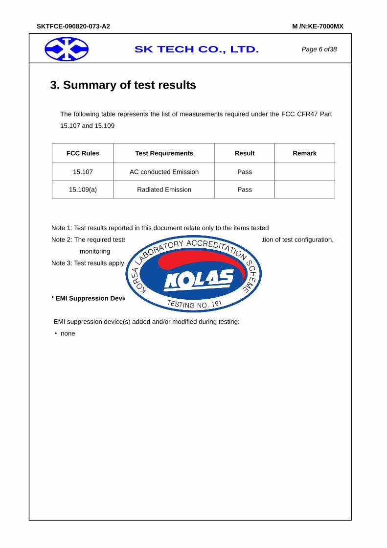
3. Summary of test results
The following table represents the list of measurements required under the FCC CFR47 Part
15.107 and 15.109
FCC Rules Test Requirements Result Remark
15.107 AC conducted Emission Pass
15.109(a) Radiated Emission Pass
Note 1: Test results reported in this document relate only to the items tested
Note 2: The required tests demonstrated compliance as per client declaration of test configuration,
monitoring
Note 3: Test results apply only to the item(s) tested
* EMI Suppression Device(s)
EMI suppression device(s) added and/or modified during testing:
• none
SK TECH CO., LTD. Page 7 of38
SKTFCE-090820-073-A2 M /N:KE-7000MX
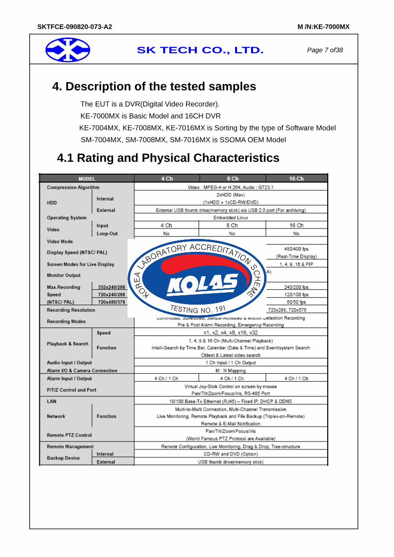
4. Description of the tested samples The EUT is a DVR(Digital Video Recorder). KE-7000MX is Basic Model and 16CH DVR KE-7004MX, KE-7008MX, KE-7016MX is Sorting by the type of Software Model
SM-7004MX, SM-7008MX, SM-7016MX is SSOMA OEM Model
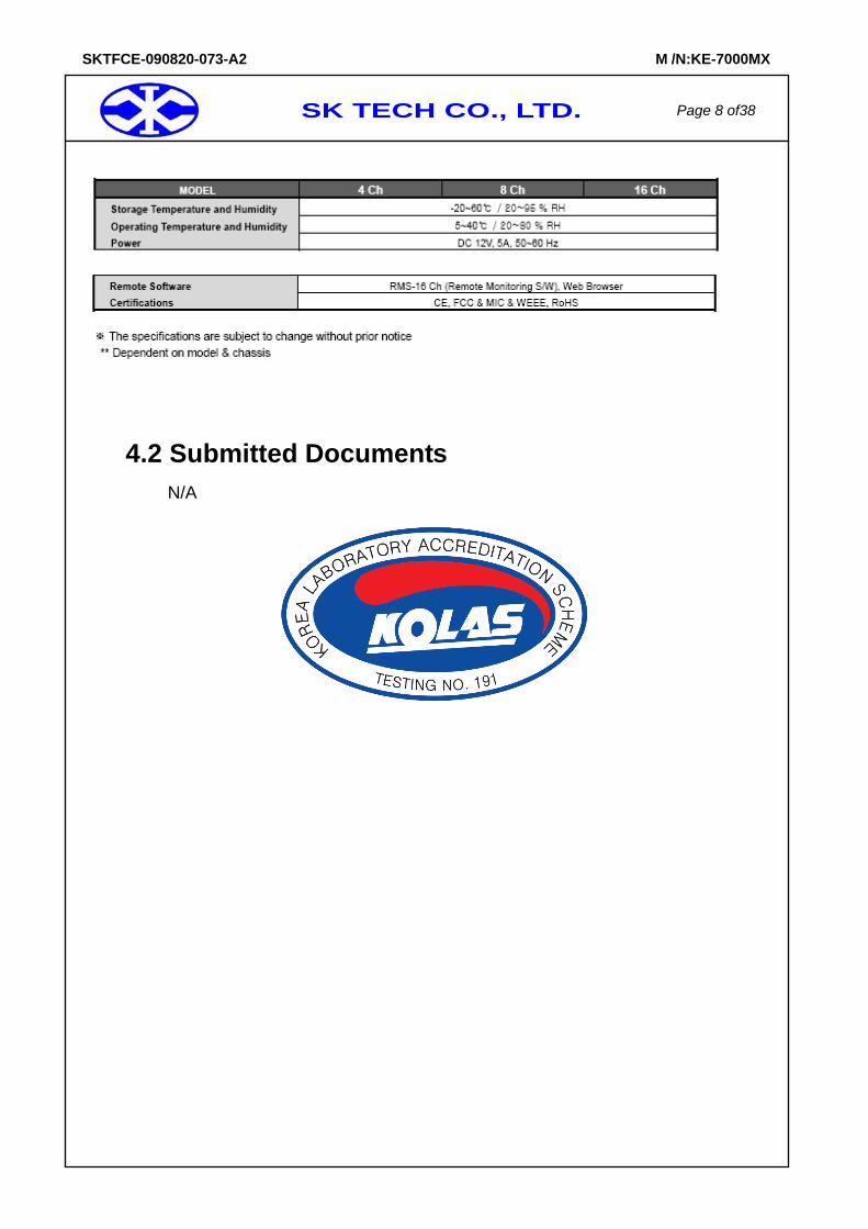
4.1 Rating and Physical Characteristics
SK TECH CO., LTD. Page 8 of38
SKTFCE-090820-073-A2 M /N:KE-7000MX
4.2 Submitted Documents
N/A
SK TECH CO., LTD. Page 9 of38
SKTFCE-090820-073-A2 M /N:KE-7000MX
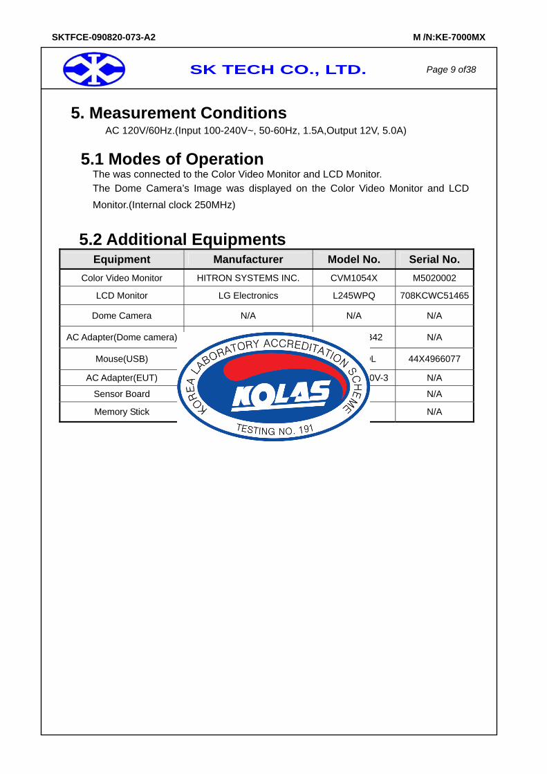
5. Measurement Conditions AC 120V/60Hz.(Input 100-240V~, 50-60Hz, 1.5A,Output 12V, 5.0A)
5.1 Modes of Operation The was connected to the Color Video Monitor and LCD Monitor. The Dome Camera’s Image was displayed on the Color Video Monitor and LCD Monitor.(Internal clock 250MHz)
5.2 Additional Equipments Equipment Manufacturer Model No. Serial No.
Color Video Monitor HITRON SYSTEMS INC. CVM1054X M5020002
LCD Monitor LG Electronics L245WPQ 708KCWC51465
Dome Camera N/A N/A N/A
AC Adapter(Dome camera) HUA JUNG COMP.CO., LTD HASU11FB42 N/A
Mouse(USB) DONGGUAN PRIMAX ELETRONICS LTD MO28UOL 44X4966077
AC Adapter(EUT) Sino-American SA165A-1250V-3 N/A
Sensor Board N/A N/A N/A
Memory Stick N/A N/A N/A
SK TECH CO., LTD. Page 10 of38
SKTFCE-090820-073-A2 M /N:KE-7000MX
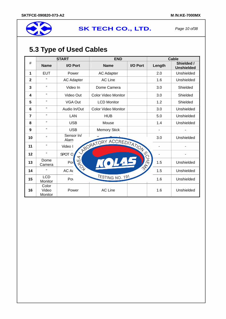
5.3 Type of Used Cables
START END Cable # Name I/O Port Name I/O Port Length Shielded /
Unshielded 1 EUT Power AC Adapter 2.0 Unshielded
2 " AC Adapter AC Line 1.6 Unshielded
3 " Video In Dome Camera 3.0 Shielded
4 " Video Out Color Video Monitor 3.0 Shielded
5 " VGA Out LCD Monitor 1.2 Shielded
6 " Audio In/Out Color Video Monitor 3.0 Unshielded
7 " LAN HUB 5.0 Unshielded
8 " USB Mouse 1.4 Unshielded
9 " USB Memory Stick - -
10 " Sensor In/ Alarm Out Sensor Board 3.0 Unshielded
11 " Video In(x15) 75Ω Termination - -
12 " SPOT OUT (x1) 75Ω Termination - -
13 Dome Camera Power AC Adapter 1.5 Unshielded
14 " AC Adapter AC Line 1.5 Unshielded
15 LCD Monitor Power AC Line 1.6 Unshielded
16 Color Video
Monitor Power AC Line 1.6 Unshielded
SK TECH CO., LTD. Page 11 of38
SKTFCE-090820-073-A2 M /N:KE-7000MX
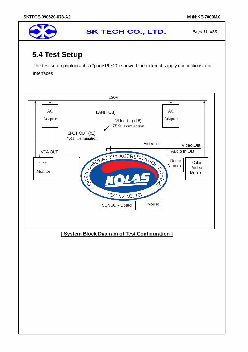
5.4 Test Setup
The test setup photographs (#page19 ~20) showed the external supply connections and Interfaces
``
[ System Block Diagram of Test Configuration ]
VGA OUT
Video In (x15) 75Ω Termination
120V
Color Video
Monitor
Video Out
SENSOR In
ALARM Out
LCD
Monitor
Audio In/Out
Memory Stick
Mouse
USB
Dome Camera
AC
Adapter
AC
Adapter
EUTDVR(Digital Video
Recoreder)
LAN(HUB)
SENSOR Board
SPOT OUT (x1) 75Ω Termination
Video in
SK TECH CO., LTD. Page 12 of38
SKTFCE-090820-073-A2 M /N:KE-7000MX
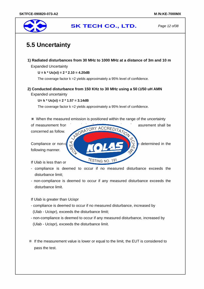
5.5 Uncertainty 1) Radiated disturbances from 30 MHz to 1000 MHz at a distance of 3m and 10 m
Expanded Uncertainty U = k * Uc(xi) = 2 * 2.10 = 4.20dB
The coverage factor k =2 yields approximately a 95% level of confidence.
2) Conducted disturbance from 150 KHz to 30 MHz using a 50 Ω/50 uH AMN Expanded uncertainty
U= k * Uc(xi) = 2 * 1.57 = 3.14dB
The coverage factor k =2 yields approximately a 95% level of confidence.
※ When the measured emission is positioned within the range of the uncertainty of measurement from the emission limit, the uncertainty of measurement shall be concerned as follow. Compliance or non-compliance with a disturbance limit shall be determined in the following manner. If Ulab is less than or equal to Ucispr - compliance is deemed to occur if no measured disturbance exceeds the
disturbance limit; - non-compliance is deemed to occur if any measured disturbance exceeds the
disturbance limit. If Ulab is greater than Ucispr - compliance is deemed to occur if no measured disturbance, increased by (Ulab - Ucispr), exceeds the disturbance limit;
- non-compliance is deemed to occur if any measured disturbance, increased by (Ulab - Ucispr), exceeds the disturbance limit.
※ If the measurement value is lower or equal to the limit, the EUT is considered to
pass the test.
SK TECH CO., LTD. Page 13 of38
SKTFCE-090820-073-A2 M /N:KE-7000MX
6. Test Results
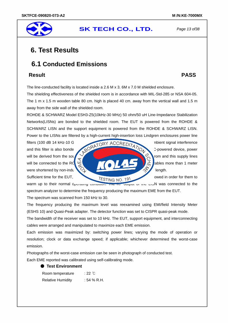
6.1 Conducted Emissions Result PASS
The line-conducted facility is located inside a 2.6 M x 3. 6M x 7.0 M shielded enclosure.
The shielding effectiveness of the shielded room is in accordance with MIL-Std-285 or NSA 604-05.
The 1 m x 1.5 m wooden table 80 cm. high is placed 40 cm. away from the vertical wall and 1.5 m
away from the side wall of the shielded room.
ROHDE & SCHWARZ Model ESH3-Z5(10kHz-30 MHz) 50 ohm/50 uH Line-Impedance Stabilization
Networks(LISNs) are bonded to the shielded room. The EUT is powered from the ROHDE &
SCHWARZ LISN and the support equipment is powered from the ROHDE & SCHWARZ LISN.
Power to the LISNs are filtered by a high-current high-insertion loss Lindgren enclosures power line
filters (100 dB 14 kHz-10 GHz). The purpose of the filter is to attenuate ambient signal interference
and this filter is also bonded to the shielded enclosure. If the EUT is a DC-powered device, power
will be derived from the source power supply it normally will be powered from and this supply lines
will be connected to the ROHDE & SCHWARZ LISN. All interconnecting cables more than 1 meter
were shortened by non-inductive bundling (serpentine fashion) to a 1-meter length.
Sufficient time for the EUT, support equipment, and test equipment was allowed in order for them to
warm up to their normal operating condition. The RF output of the LISN was connected to the
spectrum analyzer to determine the frequency producing the maximum EME from the EUT.
The spectrum was scanned from 150 kHz to 30.
The frequency producing the maximum level was reexamined using EMI/field Intensity Meter
(ESHS 10) and Quasi-Peak adapter. The detector function was set to CISPR quasi-peak mode.
The bandwidth of the receiver was set to 10 kHz. The EUT, support equipment, and interconnecting
cables were arranged and manipulated to maximize each EME emission.
Each emission was maximized by: switching power lines; varying the mode of operation or
resolution; clock or data exchange speed; if applicable; whichever determined the worst-case
emission.
Photographs of the worst-case emission can be seen in photograph of conducted test.
Each EME reported was calibrated using self-calibrating mode. Test Environment
Room temperature : 22
Relative Humidity : 54 % R.H.
SK TECH CO., LTD. Page 14 of38
SKTFCE-090820-073-A2 M /N:KE-7000MX
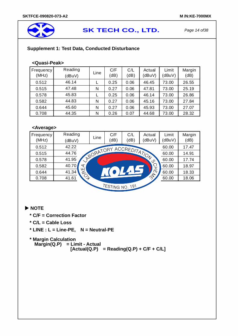
Supplement 1: Test Data, Conducted Disturbance <Quasi-Peak>
0.512 L 0.25 0.06 46.45 73.00 26.550.515 N 0.27 0.06 47.81 73.00 25.190.578 L 0.25 0.06 46.14 73.00 26.860.582 N 0.27 0.06 45.16 73.00 27.840.644 N 0.27 0.06 45.93 73.00 27.070.708 N 0.26 0.07 44.68 73.00 28.32
45.6044.35
46.1447.4845.8344.83
Frequency(MHz)
ReadingLine C/F
(dB)(dBuV)C/L(dB)
Actual(dBuV)
Limit(dBuV)
Margin(dB)
<Average>
0.512 L 0.25 0.06 42.53 60.00 17.470.515 N 0.27 0.06 45.09 60.00 14.910.578 L 0.25 0.06 42.26 60.00 17.740.582 N 0.27 0.06 41.03 60.00 18.970.644 N 0.27 0.06 41.67 60.00 18.330.708 N 0.26 0.07 41.94 60.00 18.06
C/L(dB)
Actual(dBuV)
Limit(dBuV)
Margin(dB)
Frequency(MHz)
ReadingLine C/F
(dB)(dBuV)
41.3441.61
42.2244.7641.9540.70
NOTE * C/F = Correction Factor * C/L = Cable Loss * LINE : L = Line-PE, N = Neutral-PE
* Margin Calculation Margin(Q.P) = Limit - Actual
[Actual(Q.P) = Reading(Q.P) + C/F + C/L]

SK TECH CO., LTD. Page 15 of38
SKTFCE-090820-073-A2 M /N:KE-7000MX
Supplement 2 : Spectral Diagram, LINE – PE
SK TECH CO., LTD. Page 16 of38
SKTFCE-090820-073-A2 M /N:KE-7000MX
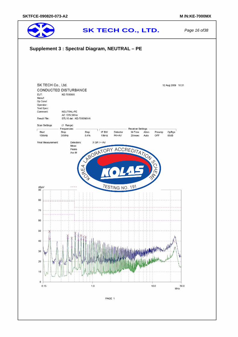
Supplement 3 : Spectral Diagram, NEUTRAL – PE
SK TECH CO., LTD. Page 17 of38
SKTFCE-090820-073-A2 M /N:KE-7000MX
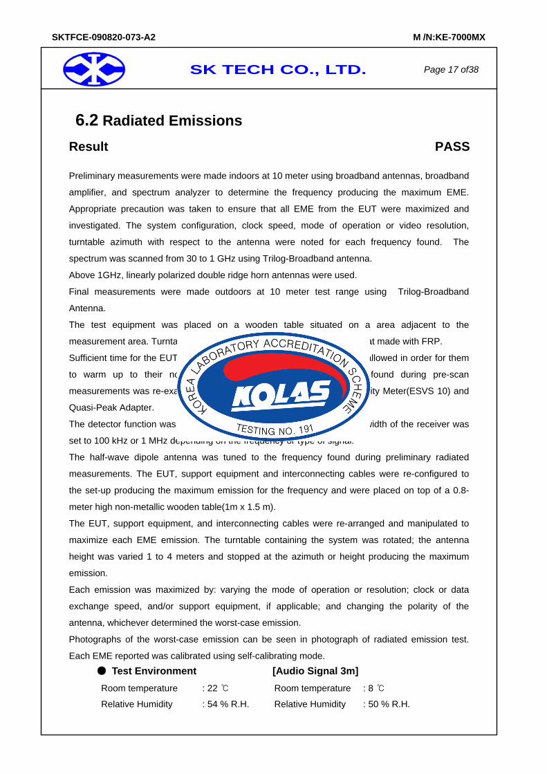
6.2 Radiated Emissions Result PASS
Preliminary measurements were made indoors at 10 meter using broadband antennas, broadband
amplifier, and spectrum analyzer to determine the frequency producing the maximum EME.
Appropriate precaution was taken to ensure that all EME from the EUT were maximized and
investigated. The system configuration, clock speed, mode of operation or video resolution,
turntable azimuth with respect to the antenna were noted for each frequency found. The
spectrum was scanned from 30 to 1 GHz using Trilog-Broadband antenna.
Above 1GHz, linearly polarized double ridge horn antennas were used.
Final measurements were made outdoors at 10 meter test range using Trilog-Broadband
Antenna.
The test equipment was placed on a wooden table situated on a area adjacent to the
measurement area. Turntable was to protect from weather in the dome that made with FRP.
Sufficient time for the EUT, support equipment, and test equipment was allowed in order for them
to warm up to their normal operating condition. Each frequency found during pre-scan
measurements was re-examined and investigated using EMI/Field Intensity Meter(ESVS 10) and
Quasi-Peak Adapter.
The detector function was set to CISPR quasi-peak mode and the bandwidth of the receiver was
set to 100 kHz or 1 MHz depending on the frequency or type of signal.
The half-wave dipole antenna was tuned to the frequency found during preliminary radiated
measurements. The EUT, support equipment and interconnecting cables were re-configured to
the set-up producing the maximum emission for the frequency and were placed on top of a 0.8-
meter high non-metallic wooden table(1m x 1.5 m).
The EUT, support equipment, and interconnecting cables were re-arranged and manipulated to
maximize each EME emission. The turntable containing the system was rotated; the antenna
height was varied 1 to 4 meters and stopped at the azimuth or height producing the maximum
emission.
Each emission was maximized by: varying the mode of operation or resolution; clock or data
exchange speed, and/or support equipment, if applicable; and changing the polarity of the
antenna, whichever determined the worst-case emission.
Photographs of the worst-case emission can be seen in photograph of radiated emission test.
Each EME reported was calibrated using self-calibrating mode.
Test Environment [Audio Signal 3m]
Room temperature : 22 Room temperature : 8
Relative Humidity : 54 % R.H. Relative Humidity : 50 % R.H.
SK TECH CO., LTD. Page 18 of38
SKTFCE-090820-073-A2 M /N:KE-7000MX
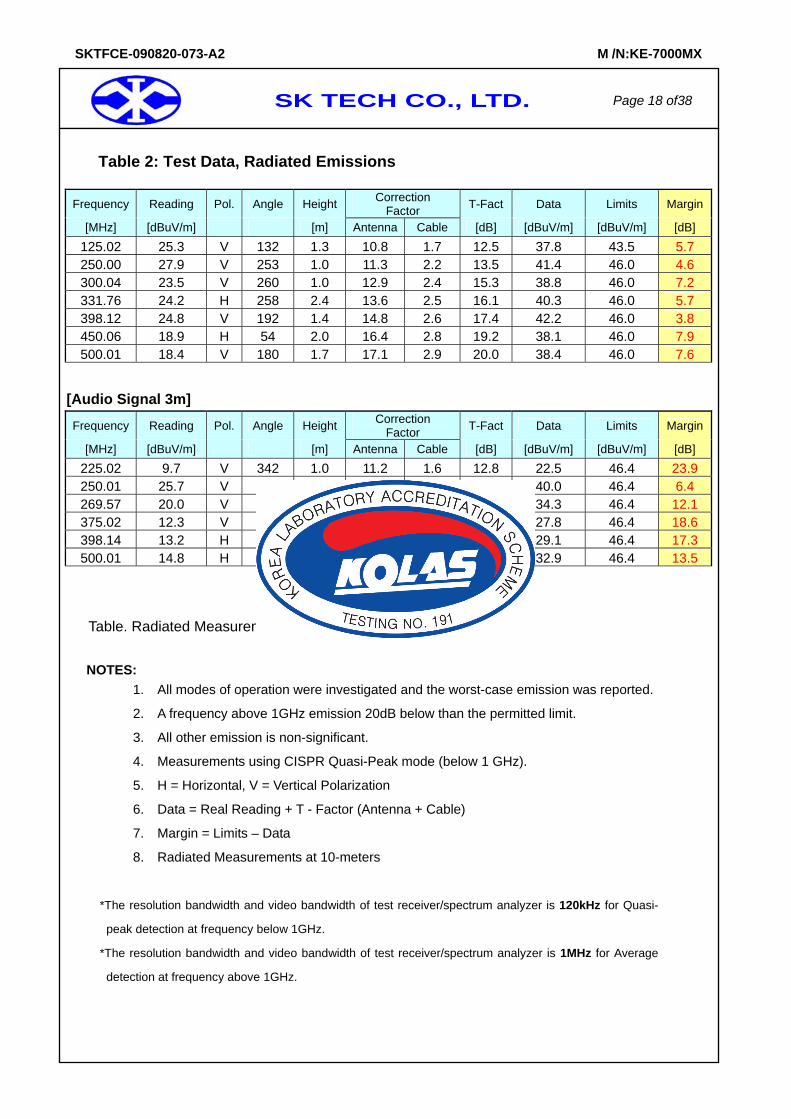
Table 2: Test Data, Radiated Emissions
Frequency Reading Pol. Angle Height Correction Factor T-Fact Data Limits Margin
[MHz] [dBuV/m] [m] Antenna Cable [dB] [dBuV/m] [dBuV/m] [dB] 125.02 25.3 V 132 1.3 10.8 1.7 12.5 37.8 43.5 5.7 250.00 27.9 V 253 1.0 11.3 2.2 13.5 41.4 46.0 4.6 300.04 23.5 V 260 1.0 12.9 2.4 15.3 38.8 46.0 7.2 331.76 24.2 H 258 2.4 13.6 2.5 16.1 40.3 46.0 5.7 398.12 24.8 V 192 1.4 14.8 2.6 17.4 42.2 46.0 3.8 450.06 18.9 H 54 2.0 16.4 2.8 19.2 38.1 46.0 7.9 500.01 18.4 V 180 1.7 17.1 2.9 20.0 38.4 46.0 7.6
[Audio Signal 3m]
Frequency Reading Pol. Angle Height Correction Factor T-Fact Data Limits Margin
[MHz] [dBuV/m] [m] Antenna Cable [dB] [dBuV/m] [dBuV/m] [dB] 225.02 9.7 V 342 1.0 11.2 1.6 12.8 22.5 46.4 23.9 250.01 25.7 V 314 1.0 12.6 1.7 14.3 40.0 46.4 6.4 269.57 20.0 V 249 1.1 12.6 1.7 14.3 34.3 46.4 12.1 375.02 12.3 V 342 1.0 13.5 2.0 15.5 27.8 46.4 18.6 398.14 13.2 H 87 2.0 13.8 2.1 15.9 29.1 46.4 17.3 500.01 14.8 H 332 3.3 15.8 2.3 18.1 32.9 46.4 13.5
Table. Radiated Measurements at 10-meters
NOTES:
1. All modes of operation were investigated and the worst-case emission was reported.
2. A frequency above 1GHz emission 20dB below than the permitted limit.
3. All other emission is non-significant.
4. Measurements using CISPR Quasi-Peak mode (below 1 GHz).
5. H = Horizontal, V = Vertical Polarization
6. Data = Real Reading + T - Factor (Antenna + Cable)
7. Margin = Limits – Data
8. Radiated Measurements at 10-meters
*The resolution bandwidth and video bandwidth of test receiver/spectrum analyzer is 120kHz for Quasi-
peak detection at frequency below 1GHz.
*The resolution bandwidth and video bandwidth of test receiver/spectrum analyzer is 1MHz for Average
detection at frequency above 1GHz.
SK TECH CO., LTD. Page 19 of38
SKTFCE-090820-073-A2 M /N:KE-7000MX
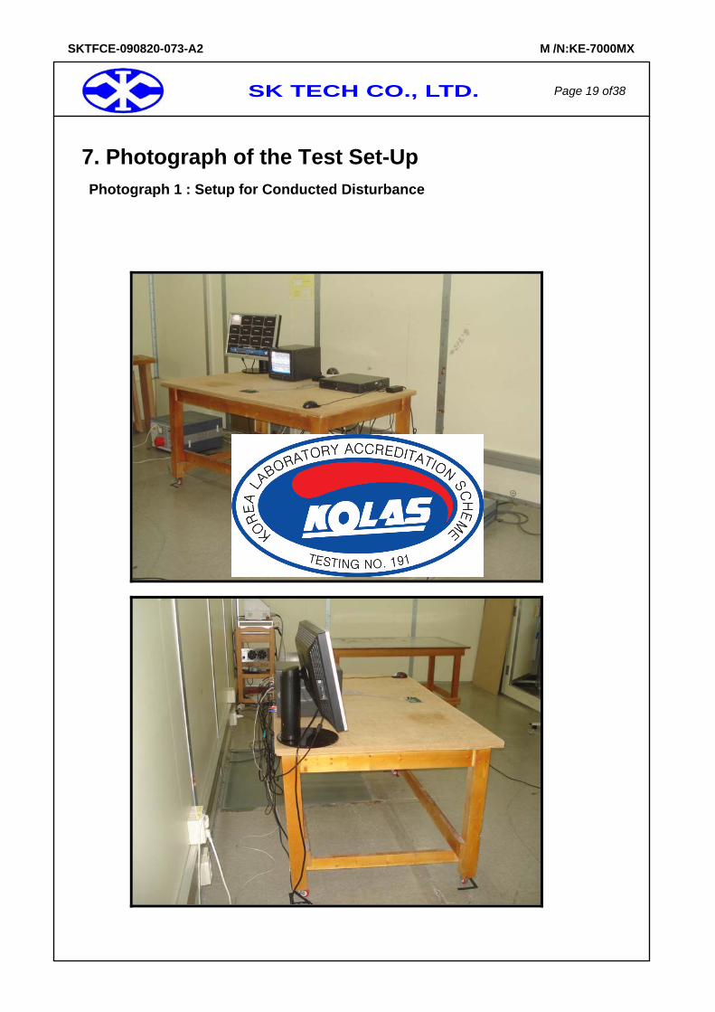
7. Photograph of the Test Set-Up Photograph 1 : Setup for Conducted Disturbance
SK TECH CO., LTD. Page 20 of38
SKTFCE-090820-073-A2 M /N:KE-7000MX
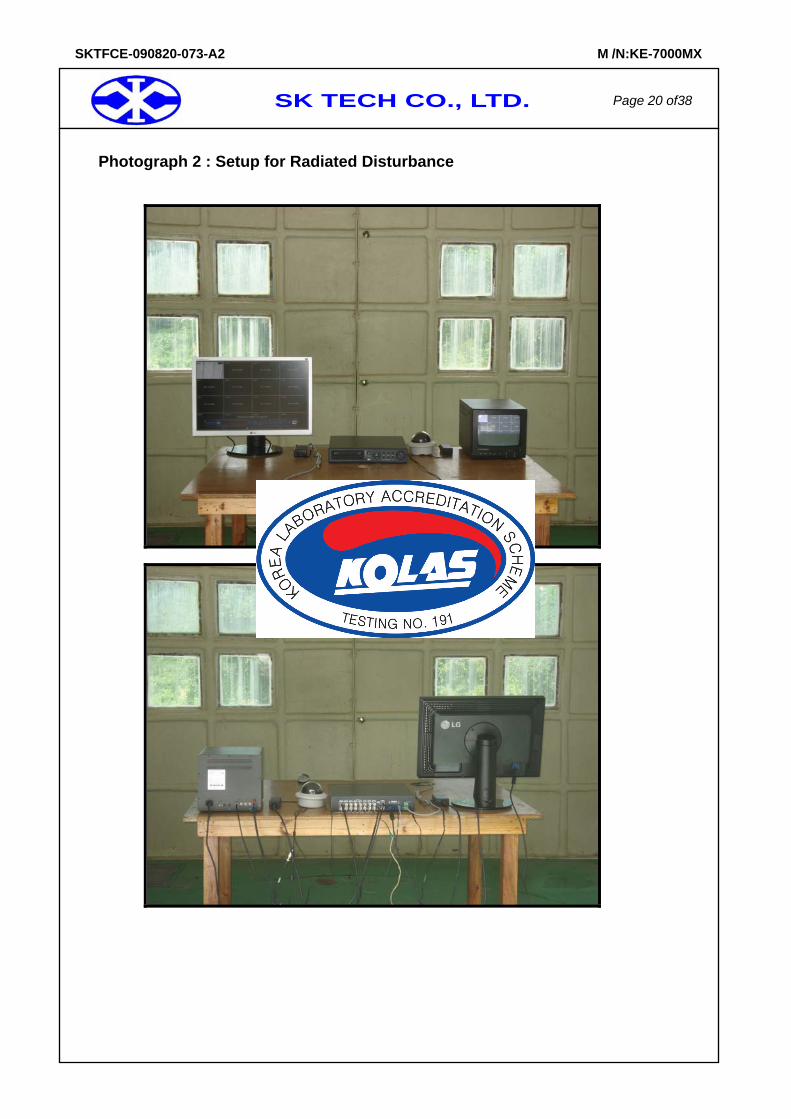
Photograph 2 : Setup for Radiated Disturbance
SK TECH CO., LTD. Page 21 of38
SKTFCE-090820-073-A2 M /N:KE-7000MX
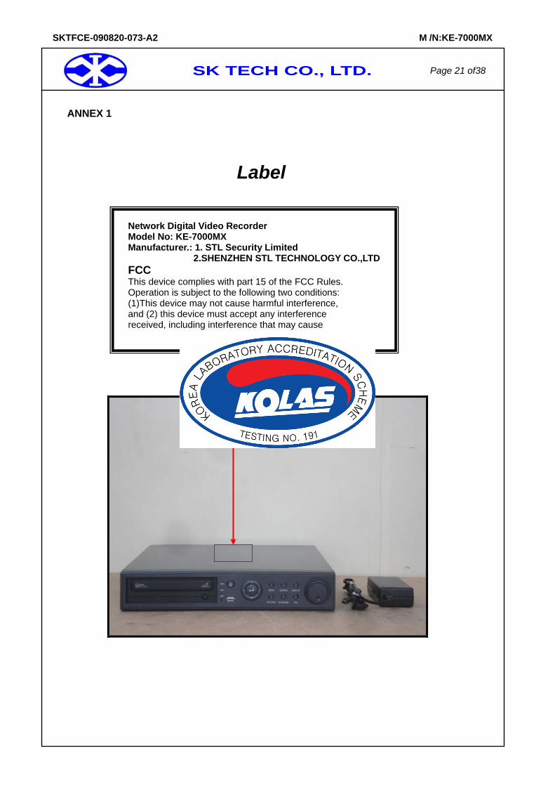
ANNEX 1
Label
Network Digital Video Recorder Model No: KE-7000MX Manufacturer.: 1. STL Security Limited 2.SHENZHEN STL TECHNOLOGY CO.,LTDFCC This device complies with part 15 of the FCC Rules. Operation is subject to the following two conditions: (1)This device may not cause harmful interference, and (2) this device must accept any interference received, including interference that may cause
SK TECH CO., LTD. Page 22 of38
SKTFCE-090820-073-A2 M /N:KE-7000MX
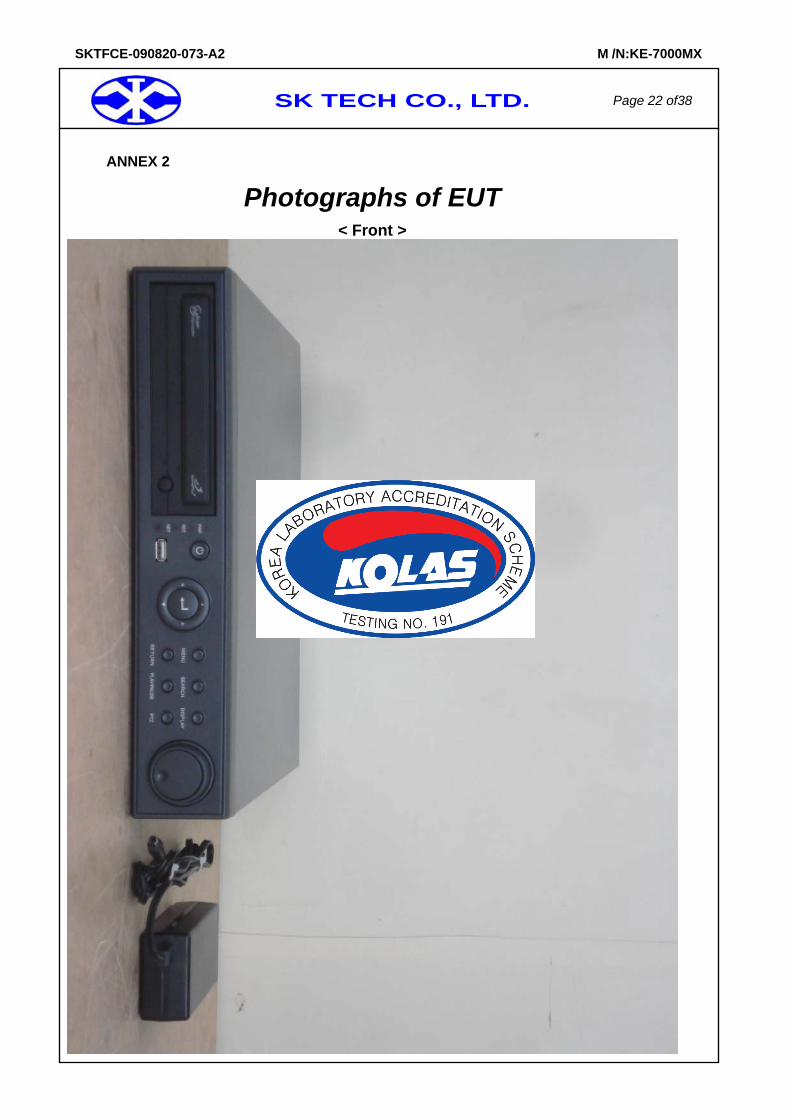
ANNEX 2
Photographs of EUT < Front >
SK TECH CO., LTD. Page 23 of38
SKTFCE-090820-073-A2 M /N:KE-7000MX
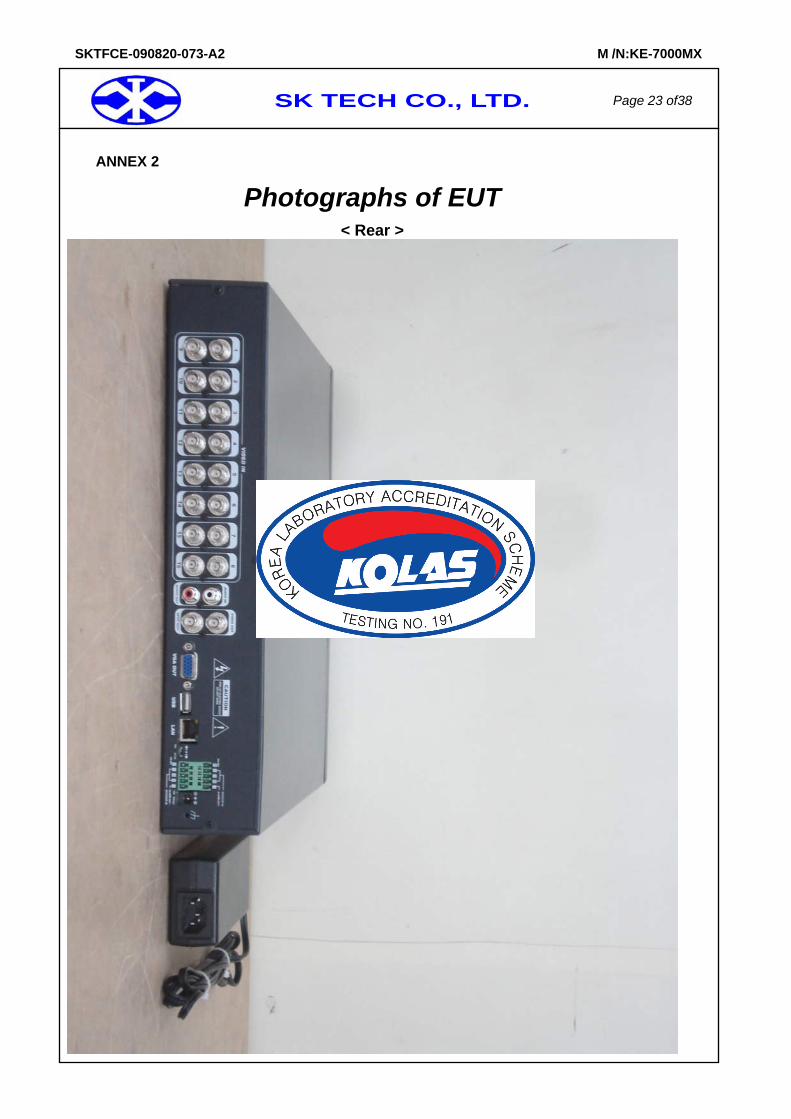
ANNEX 2
Photographs of EUT < Rear >
SK TECH CO., LTD. Page 24 of38
SKTFCE-090820-073-A2 M /N:KE-7000MX
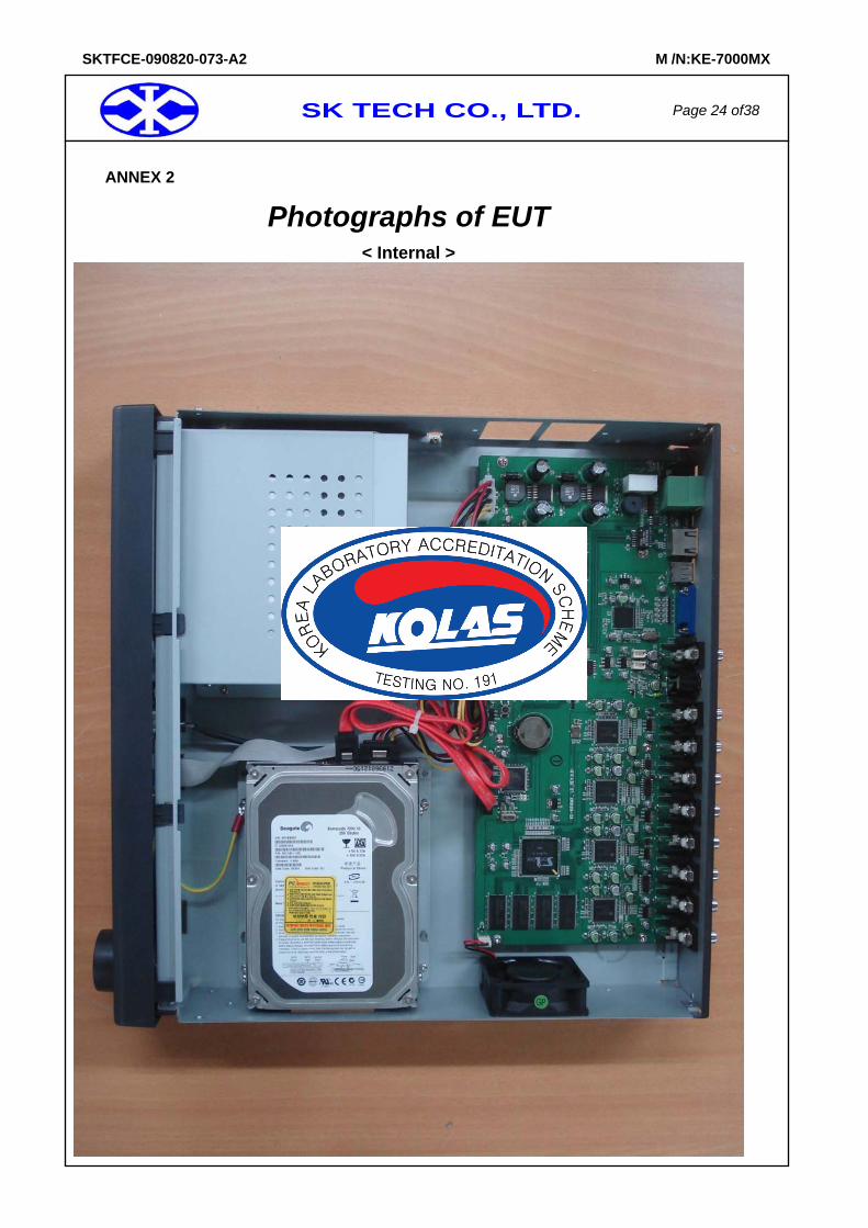
ANNEX 2
Photographs of EUT < Internal >
SK TECH CO., LTD. Page 25 of38
SKTFCE-090820-073-A2 M /N:KE-7000MX
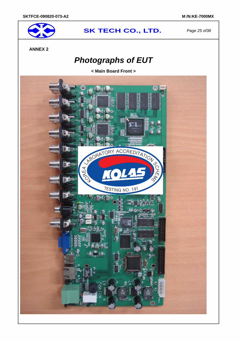
ANNEX 2
Photographs of EUT < Main Board Front >
SK TECH CO., LTD. Page 26 of38
SKTFCE-090820-073-A2 M /N:KE-7000MX
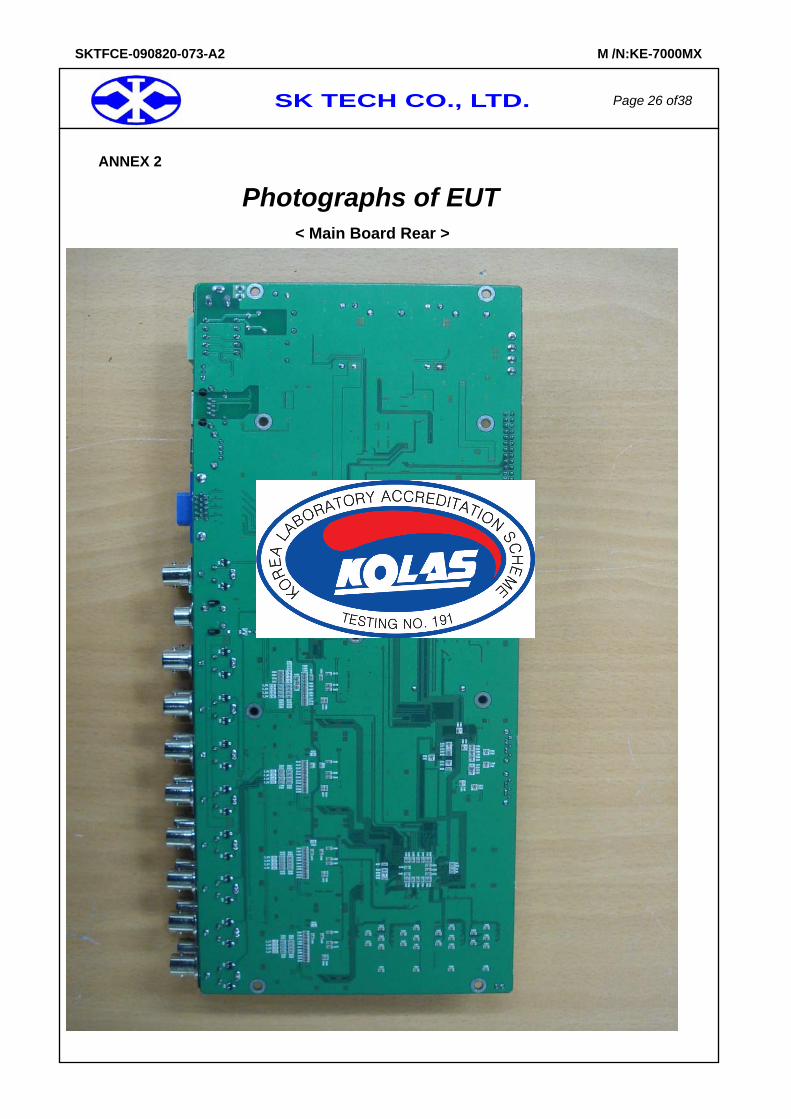
ANNEX 2
Photographs of EUT
< Main Board Rear >
SK TECH CO., LTD. Page 27 of38
SKTFCE-090820-073-A2 M /N:KE-7000MX
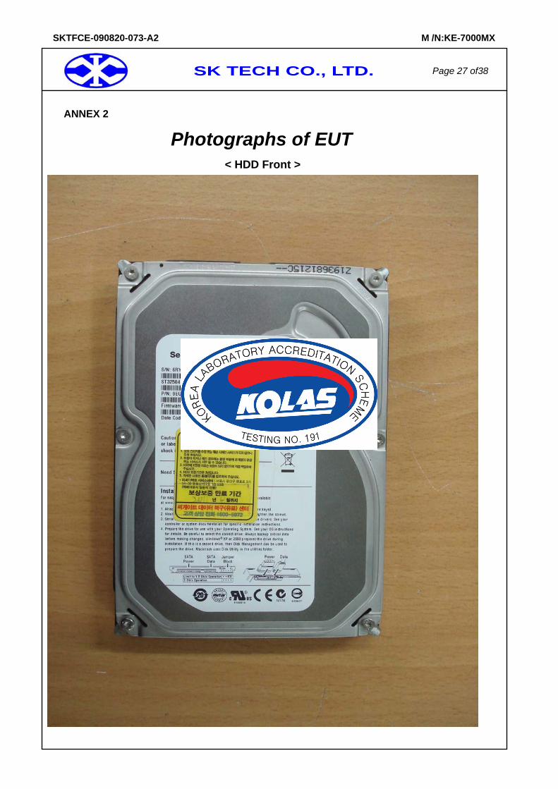
ANNEX 2
Photographs of EUT
< HDD Front >
SK TECH CO., LTD. Page 28 of38
SKTFCE-090820-073-A2 M /N:KE-7000MX
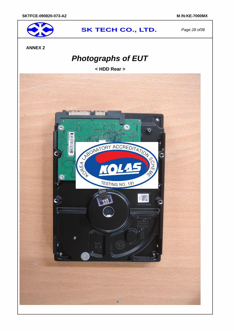
ANNEX 2
Photographs of EUT
< HDD Rear >
SK TECH CO., LTD. Page 29 of38
SKTFCE-090820-073-A2 M /N:KE-7000MX
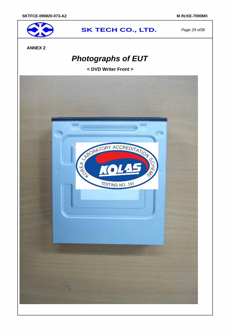
ANNEX 2
Photographs of EUT
< DVD Writer Front >
SK TECH CO., LTD. Page 30 of38
SKTFCE-090820-073-A2 M /N:KE-7000MX
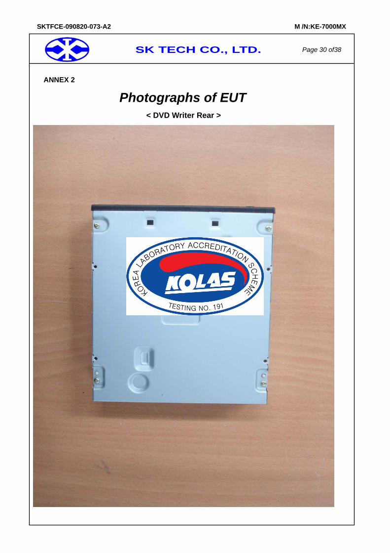
ANNEX 2
Photographs of EUT
< DVD Writer Rear >
SK TECH CO., LTD. Page 31 of38
SKTFCE-090820-073-A2 M /N:KE-7000MX
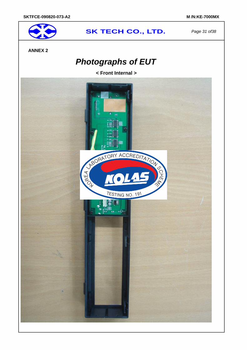
ANNEX 2
Photographs of EUT
< Front Internal >
SK TECH CO., LTD. Page 32 of38
SKTFCE-090820-073-A2 M /N:KE-7000MX
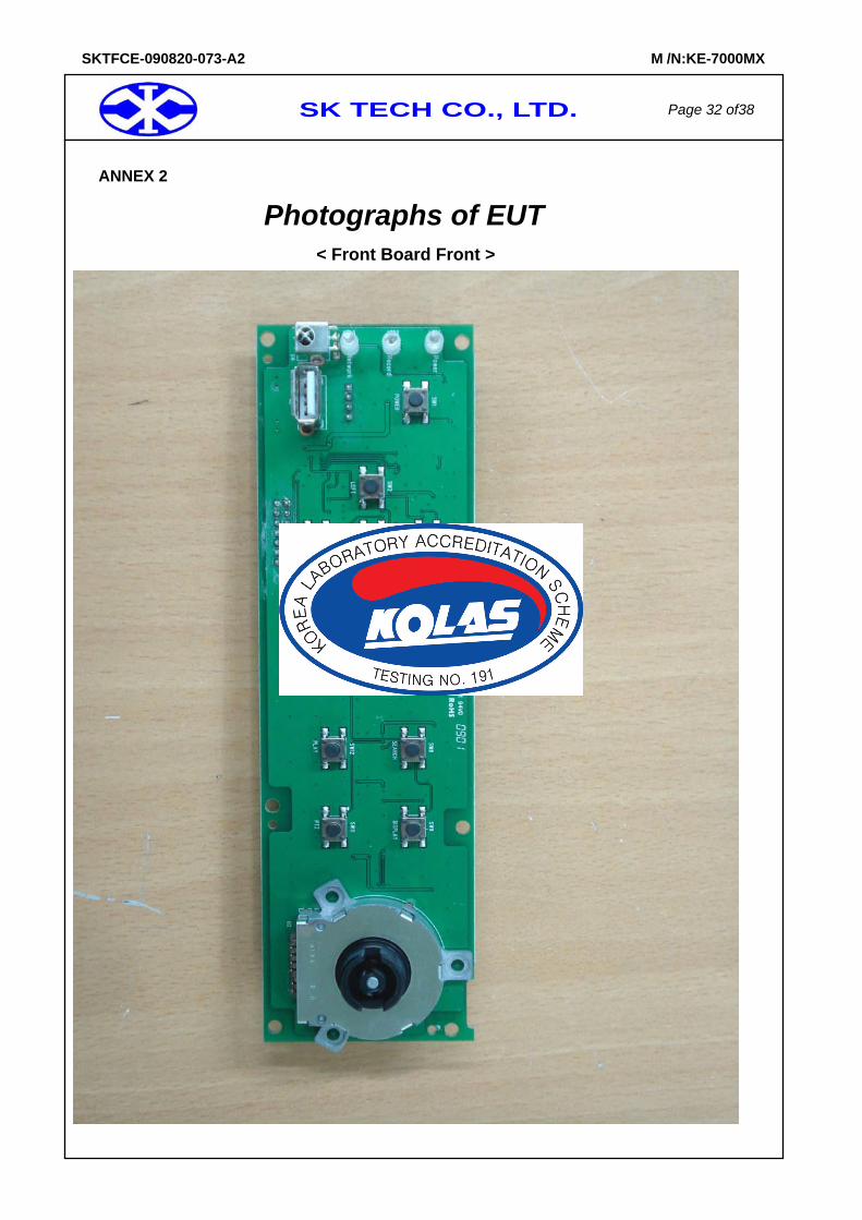
ANNEX 2
Photographs of EUT
< Front Board Front >
SK TECH CO., LTD. Page 33 of38
SKTFCE-090820-073-A2 M /N:KE-7000MX
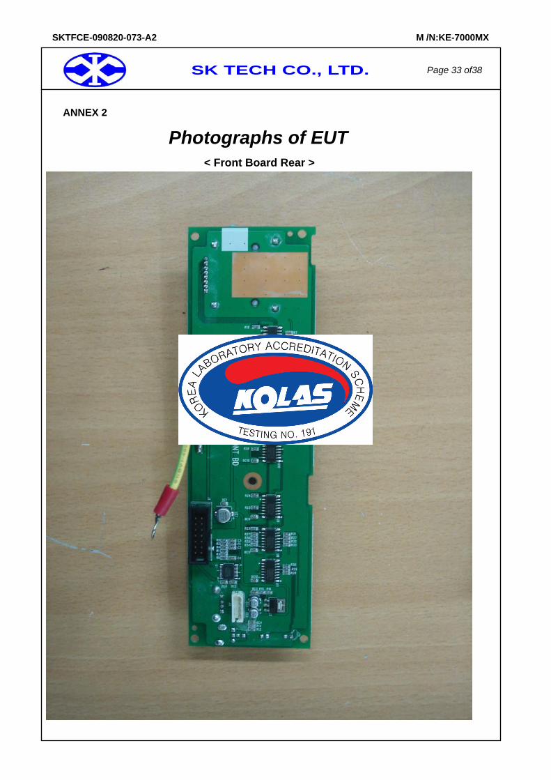
ANNEX 2
Photographs of EUT
< Front Board Rear >
SK TECH CO., LTD. Page 34 of38
SKTFCE-090820-073-A2 M /N:KE-7000MX
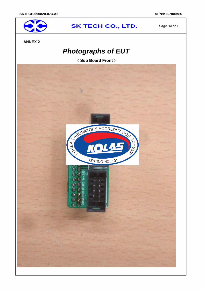
ANNEX 2
Photographs of EUT
< Sub Board Front >
SK TECH CO., LTD. Page 35 of38
SKTFCE-090820-073-A2 M /N:KE-7000MX
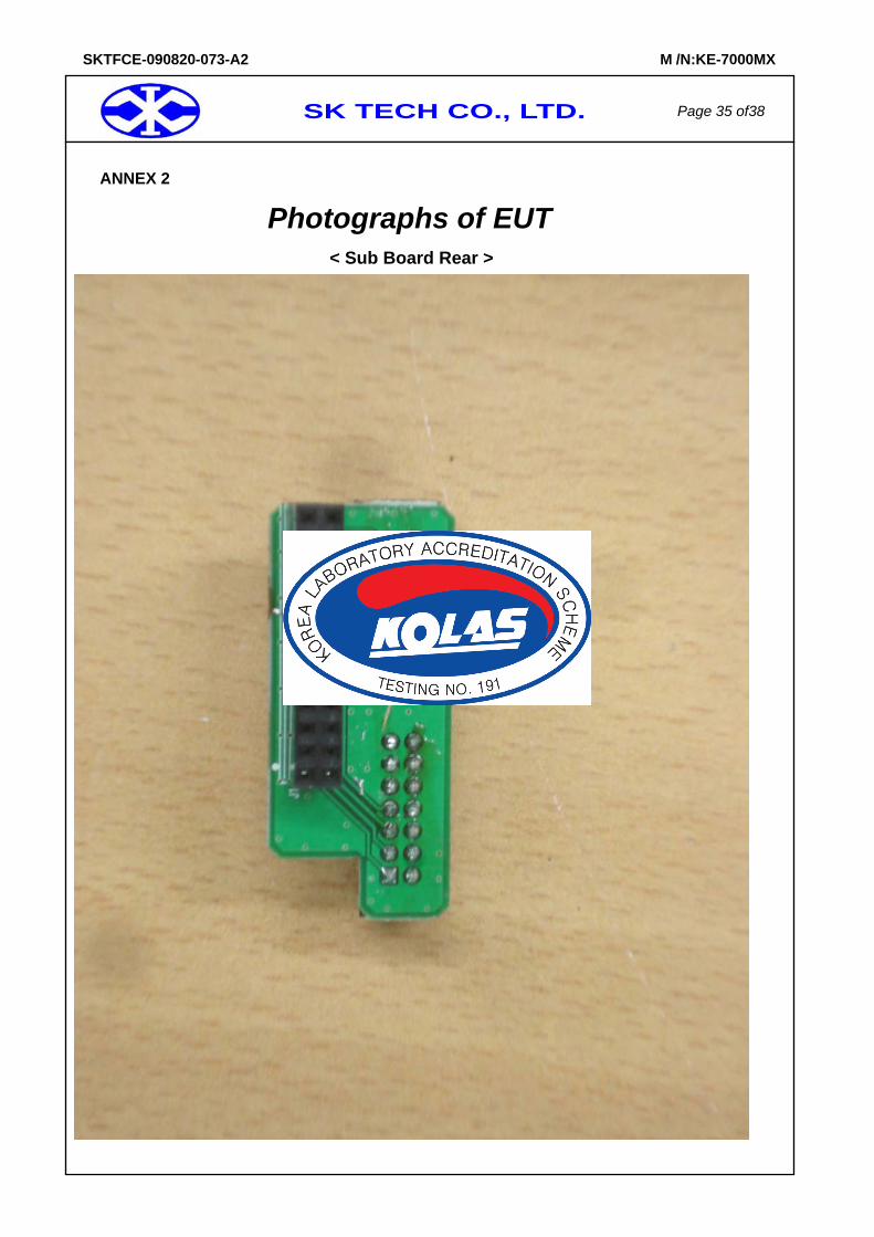
ANNEX 2
Photographs of EUT
< Sub Board Rear >
SK TECH CO., LTD. Page 36 of38
SKTFCE-090820-073-A2 M /N:KE-7000MX
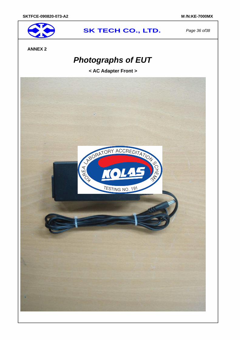
ANNEX 2
Photographs of EUT
< AC Adapter Front >
SK TECH CO., LTD. Page 37 of38
SKTFCE-090820-073-A2 M /N:KE-7000MX
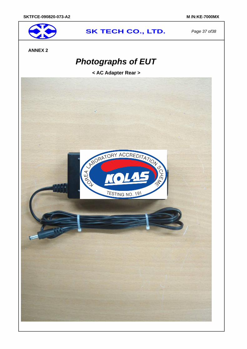
ANNEX 2
Photographs of EUT
< AC Adapter Rear >
SK TECH CO., LTD. Page 38 of38
SKTFCE-090820-073-A2 M /N:KE-7000MX
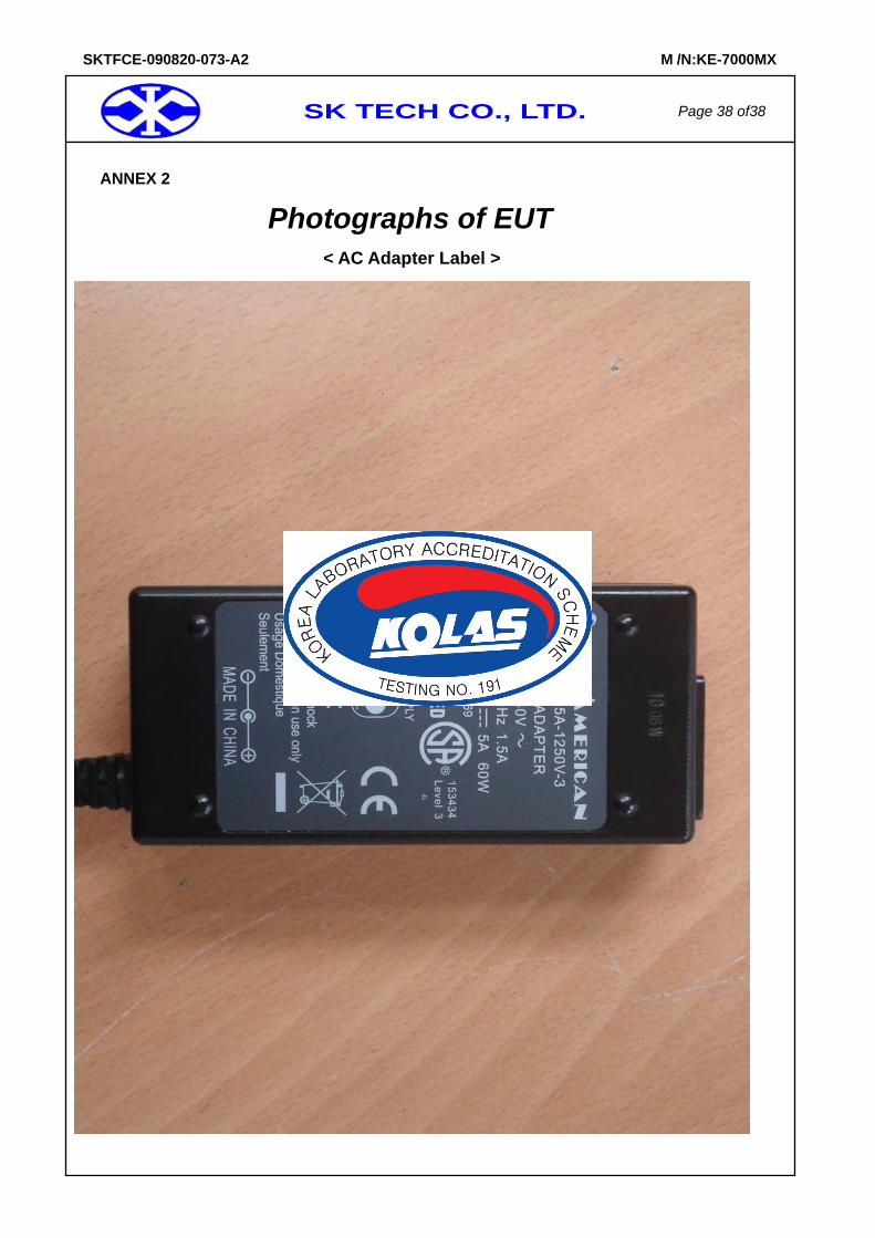
ANNEX 2
Photographs of EUT
< AC Adapter Label >