Embed Size (px)
Citation preview
INSTALLATION AND MAINTENANCE MANUAL
SKD
ENG
LISH
64 76 93 105 116 140 163 186 233 291
340 420 510 630 760 870 970 1100 1320 1570 1850 2200 2650 3000 35004000 4500 50005500 6000 6500 7000
2
General information
TABLE OF CONTENTS
1 GENERAL INFORMATION .................................................................................................................................................................................3 1.1 Symbols used in the manual .........................................................................................................................................................................3 1.2 Appropriate use of appliance ........................................................................................................................................................................3 1.3 Water treatment ............................................................................................................................................................................................3 1.4 Information for user or system manager .......................................................................................................................................................3 1.5 Safety warnings ............................................................................................................................................................................................4 1.6 Technical data plate ......................................................................................................................................................................................5 1.7 General warnings ..........................................................................................................................................................................................6
2 TECHNICAL FEATURES AND DIMENSIONS ...................................................................................................................................................7 2.1 Technical features .........................................................................................................................................................................................7 2.2 Main components .........................................................................................................................................................................................7 2.3 Smoke turbulators .........................................................................................................................................................................................8 2.4 Dimensions ...................................................................................................................................................................................................9 2.5 Operating data according to UNI 10348 .....................................................................................................................................................15
3 INSTALLATION INSTRUCTIONS .....................................................................................................................................................................17 3.1 General warnings .....................................................................................................................................................................................17 3.2 Installation rules ........................................................................................................................................................................................18 3.3 Handling ....................................................................................................................................................................................................19
3.4 Positioning in boiler room ..........................................................................................................................................................................19 3.5 Burner ........................................................................................................................................................................................................19
3.5.1 Choice of burner ...............................................................................................................................................................................19 3.5.2 Burner installation .............................................................................................................................................................................20 3.6 Connecting the flame controller to the burner ...........................................................................................................................................20 3.7 Furnace door: adjustment, opening, closing..............................................................................................................................................21 3.7.1 Boilers SKD 340÷SKD 630 ...............................................................................................................................................................21 3.7.2 Boilers SKD 760÷SKD 970 ...............................................................................................................................................................21 3.7.3 Boilers SKD 1100÷SKD 7000 ...........................................................................................................................................................22 3.7.4 Important note .................................................................................................................................................................................22 3.8 Flue gas exhaust duct connections ...........................................................................................................................................................22 3.9 Connecting the boiler to the system ..........................................................................................................................................................23 3.9.1 Recirculation pump ...........................................................................................................................................................................23
3.10 Filling the system .......................................................................................................................................................................................23 3.11 Gas connection..........................................................................................................................................................................................24
3.12 Packaging ..................................................................................................................................................................................................25 3.13 Assembly of casing ....................................................................................................................................................................................28 3.14 Electrical connections ................................................................................................................................................................................36 3.15 Panel board ...............................................................................................................................................................................................37 3.16 System water and electrical connection ....................................................................................................................................................38
3.17 First ignition ...............................................................................................................................................................................................42 3.18 Burner adjustment .....................................................................................................................................................................................43 3.19 Removing flue gas turbulators ...................................................................................................................................................................434 INSPECTION AND MAINTENANCE ................................................................................................................................................................44
Inspection and maintenance instructions ...........................................................................................................................................................44 Maintenance of the body ...................................................................................................................................................................................45
Maintenance of burner .......................................................................................................................................................................................45 Checking ignition electrode ................................................................................................................................................................................45 Components to check during yearly inspection .................................................................................................................................................45
3
General information
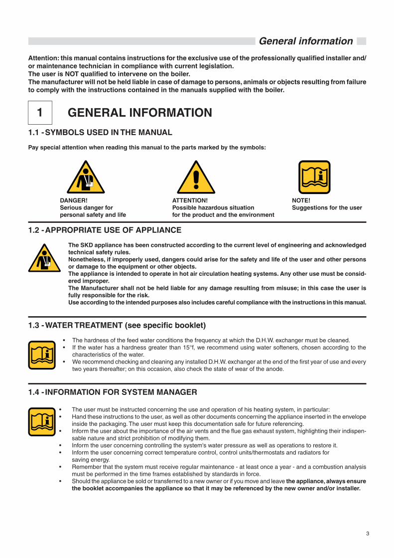
1.1 - SYMBOLS USED IN THE MANUAL
Pay special attention when reading this manual to the parts marked by the symbols:
NOTE!Suggestions for the user
ATTENTION!Possible hazardous situation for the product and the environment
DANGER!Serious danger for personal safety and life
1.2 - APPROPRIATE USE OF APPLIANCE
The SKD appliance has been constructed according to the current level of engineering and acknowledged technical safety rules. Nonetheless, if improperly used, dangers could arise for the safety and life of the user and other persons or damage to the equipment or other objects. The appliance is intended to operate in hot air circulation heating systems. Any other use must be consid-ered improper. The Manufacturer shall not be held liable for any damage resulting from misuse; in this case the user is fully responsible for the risk. Use according to the intended purposes also includes careful compliance with the instructions in this manual.
1.3 - WATER TREATMENT (see specific booklet)
• The hardness of the feed water conditions the frequency at which the D.H.W. exchanger must be cleaned.• If the water has a hardness greater than 15°f, we recommend using water softeners, chosen according to the
characteristics of the water.• We recommend checking and cleaning any installed D.H.W. exchanger at the end of the first year of use and every
two years thereafter; on this occasion, also check the state of wear of the anode.
1.4 - INFORMATION FOR SYSTEM MANAGER
• The user must be instructed concerning the use and operation of his heating system, in particular:• Hand these instructions to the user, as well as other documents concerning the appliance inserted in the envelope
inside the packaging. The user must keep this documentation safe for future referencing. • Inform the user about the importance of the air vents and the flue gas exhaust system, highlighting their indispen-
sable nature and strict prohibition of modifying them. • Inform the user concerning controlling the system's water pressure as well as operations to restore it. • Inform the user concerning correct temperature control, control units/thermostats and radiators for saving energy.• Remember that the system must receive regular maintenance - at least once a year - and a combustion analysis
must be performed in the time frames established by standards in force.• Should the appliance be sold or transferred to a new owner or if you move and leave the appliance, always ensure
the booklet accompanies the appliance so that it may be referenced by the new owner and/or installer.
1 GENERAL INFORMATION
Attention: this manual contains instructions for the exclusive use of the professionally qualified installer and/or maintenance technician in compliance with current legislation.The user is NOT qualified to intervene on the boiler.The manufacturer will not be held liable in case of damage to persons, animals or objects resulting from failure to comply with the instructions contained in the manuals supplied with the boiler.

4
General information
1.5 - SAFETY WARNINGS
ATTENTION!The appliance must be installed, adjusted and maintained by professionally qualified personnel, in compli-ance with standards and provisions in force. Incorrect installation can cause damage to persons, animals and objects for which the manufacturer cannot be held responsible.
DANGER!NEVER attempt performing maintenance or repairs on the boiler on your own initiative. Any work must be done by professionally qualified personnel. We recommend stipulating a maintenance contract.Insufficient or irregular maintenance can jeopardise the operating safety of the appliance and cause damage to persons, animals and objects for which the manufacturer cannot be held responsible.
Modifying parts connected to applianceDo not modify the following parts: - the boiler - the gas, air, water and electricity lines - the flue gas pipe, safety valves and heating water drain pipe - the construction parts which affect the operating safety of the appliance
Attention!To tighten or loosen the screwed fittings, use only appropriate fixed spanners.Incompliant use and/or inappropriate tools can cause damage (e.g. water or gas leakage).
ATTENTION!Indications for propane gas-fired appliances Make sure that the gas tank has been deaerated before installing the appliance. For state-of-the-art deaeration of the tank, contact the LPG supplier or a person qualified in compliance with law. If the tank has not been professionally deaerated, ignition problems could arise. In that case, contact the supplier of the LPG tank.
Smell of gasShould a smell of gas be perceived, follow these safety guidelines: - do not turn electric switches on or off - do not smoke - do not use the telephone - close the gas shut-off valve - air out the area where the gas leakage has occurred - inform the gas supplier or a company specialised in installation and maintenance of heating systems.
Explosive and easily flammable substancesDo not use or store explosive or easily flammable materials (e.g. petrol, paints, paper) in the room where the ap-pliance is installed.
5
General information
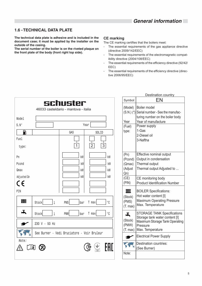
1.6 - TECHNICAL DATA PLATE
The technical data plate is adhesive and is included in the document case; it must be applied by the installer on the outside of the casing.The serial number of the boiler is on the riveted plaque on the front plate of the body (front right top side).
CE markingThe CE marking certifies that the boilers meet:- The essential requirements of the gas appliance directive
(directive 2009/142/EEC) - The essential requirements of the electromagnetic compat-
ibility directive (2004/108/EEC) - The essential requirements of the efficiency directive (92/42/
EEC)- The essential requirements of the efficiency directive (direc-
tive 2006/95/EEC)
Destination country
ENBoiler modelSerial number - See the manufac-turing number on the boiler bodyYear of manufacturePower supply1-Gas2-Diesel oil3-Naftha
Effective nominal outputOutput in condensationThermal output Thermal output Adjusted to ...
CE monitoring bodyProduct Identification Number
BOILER Specifications:Hot water content [I]Maximum Operating PressureMax. Temperature
Electrical Power Supply
Destination countries:(See Burner)
STORAGE TANK SpecificationsStorage tank water content [I]Maximum Storage Tank Operating PressureMax. Temperature
6
General information
1.7 - GENERAL WARNINGS
The instruction booklet is an integral and essential part of the product and must be kept by the user or system manager.
Read the warnings contained in this instruction booklet carefully as they provide important guidelines regarding installation, use and maintenance safety.
Keep the booklet with care for further consultation.
Installation and maintenance must be performed in compliance with standards in force according to the instructions of the man-ufacturer and by qualified and certified personnel in compliance with law.
By professionally qualified personnel we mean: personnel with specific technical skill in the field of heating system components for civil use, domestic hot water production and maintenance. Personnel must have the qualifications provided for by current legislation.
Incorrect installation or improper maintenance can cause dam-age to persons, animals or objects for which the manufacturer is not responsible.
Before performing any cleaning or maintenance, disconnect the appliance from the energy mains by acting on the switch of the system and/or through the specific cut-off devices.
Do not obstruct the terminals of the intake/exhaust ducts.
In case of failure and/or malfunctioning of the appliance, switch it off and do not try to repair it or intervene on it directly. Contact only personnel qualified in compliance with law.
Any product repairs must be performed solely by authorised personnel using original spare parts only. Failure to comply with the above can jeopardise the safety of the appliance.
To guarantee appliance efficiency and its correct operation, yearly maintenance must be performed by qualified personnel.
Should you decide not to use the appliance, parts entailing potential sources of hazard must be made safe.
Should the appliance be sold or transferred to a new owner or if you move and leave the appliance, always make sure that the instruction manual accompanies it in order to be consulted by the new owner and/or installer.
Only original accessories must be used for all appliances with optionals or kits (including electric).
This appliance is intended solely for the use for which it was expressly designed. Any other use is to be considered improper and therefore dangerous.
ATTENTIONWherever the boiler operates with a pressure jet gas burner, the appliance, not belonging to any category among those considered in Annex II of the Legislative Decree 93 of 25/02/2000 (Implementation of the Directive 97/23/EC regarding pressurised equipment), and moreover being considered by the Directive 90/396/EEC (Gas-fired appliances - transposed in Italy with Italian Presidential De-cree 661 of 15/11/1996) to which art. 1 comma 3 paragraph “f.5” refers, is excluded from the range of application of the decree itself.
7
Technical features and dimensions
2.1 - TECHNICAL FEATURES
SKD boilers are the horizontal cylindrical type with flame inver-sion in furnace and third flue gas pass in tubes.The construction fully complies with prescriptions laid down in EN 303 part 1.The components of the pressurised part, such as sheets and pipes, are made in certified carbon steel, according to the EU-RONORM 25 and EURONORM 28 tables.Welding devices and procedures are approved by TÜV (D) - UDT (PL) - SA (S) and ISPESL (I).
Up until model SKD 630, the furnace is bonded to the rear tube plate.For models SKD 760 ÷ SKD 3500, the furnace is free to expand (it is only sustained by the front tube plate).For models from SKD 4000 to SKD 7000, the furnace is bonded to the rear tube plate.The boilers are equipped with an opening door on the right or left.The outer shell is covered by a glass wool mat of thickness 60 ÷ 80 mm, itself protected by a mineral fibre fabric.
From models from SKD 4500 to SKD 7000, the outer shell is covered with a lamella felt mat 50 mm thick, itself protected by an aluminium sheet.The top part of the shell is provided with hooks for lifting the boiler.
Note: SKD 340 ÷ 7000 boilers are intended to operate with an ON/OFF burner; as an alternative, they can be equipped with a dual-stage or modulating burner, as long as the minimum heat output that can be reached is not lower than the value indicated on the technical data plate for the type of fuel used.
The boilers are provided with two ½" connections for conduits with an inside diameter of 15 mm (suitable to house 3 bulbs each).The shell has holes at the sides for the cable glands of the power, pumps, burner cables and those of any other auxiliary device.
2 TECHNICAL FEATURES AND DIMENSIONS
2.2 - MAIN COMPONENTS
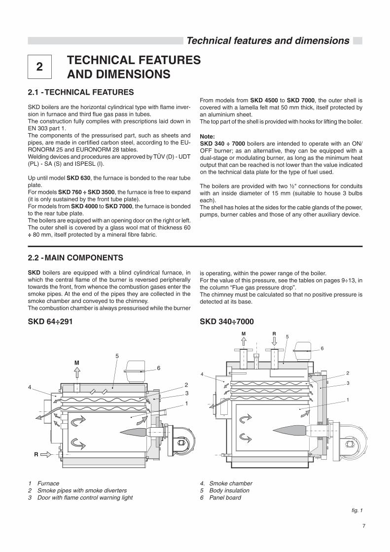
SKD boilers are equipped with a blind cylindrical furnace, in which the central flame of the burner is reversed peripherally towards the front, from whence the combustion gases enter the smoke pipes. At the end of the pipes they are collected in the smoke chamber and conveyed to the chimney.The combustion chamber is always pressurised while the burner
fig. 1
is operating, within the power range of the boiler.For the value of this pressure, see the tables on pages 9÷13, in the column “Flue gas pressure drop”.The chimney must be calculated so that no positive pressure is detected at its base.
1 Furnace2 Smoke pipes with smoke diverters3 Door with flame control warning light
4. Smoke chamber5 Body insulation6 Panel board
SKD 64÷291 SKD 340÷7000
8
Technical features and dimensions
2.3 - SMOKE TURBULATORS
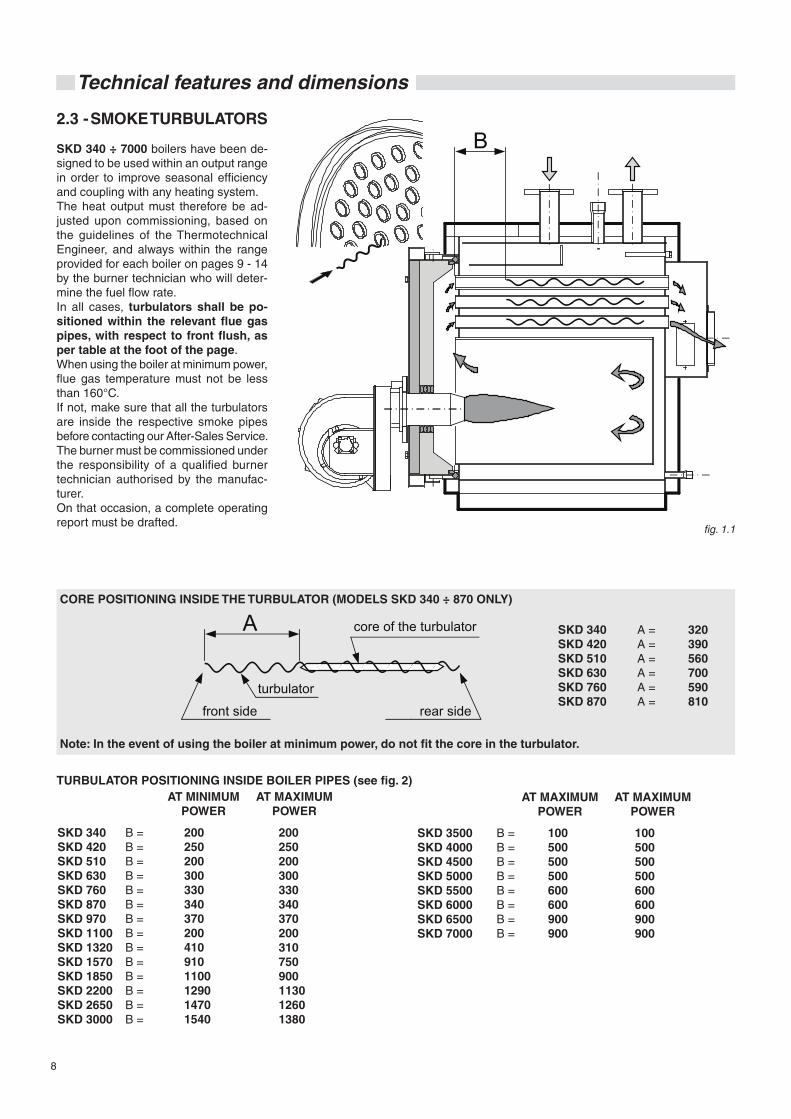
SKD 340 ÷ 7000 boilers have been de-signed to be used within an output range in order to improve seasonal efficiency and coupling with any heating system.The heat output must therefore be ad-justed upon commissioning, based on the guidelines of the Thermotechnical Engineer, and always within the range provided for each boiler on pages 9 - 14 by the burner technician who will deter-mine the fuel flow rate.In all cases, turbulators shall be po-sitioned within the relevant flue gas pipes, with respect to front flush, as per table at the foot of the page.When using the boiler at minimum power, flue gas temperature must not be less than 160°C.If not, make sure that all the turbulators are inside the respective smoke pipes before contacting our After-Sales Service.The burner must be commissioned under the responsibility of a qualified burner technician authorised by the manufac-turer.On that occasion, a complete operating report must be drafted.
CORE POSITIONING INSIDE THE TURBULATOR (MODELS SKD 340 ÷ 870 ONLY)
SKD 340SKD 420SKD 510SKD 630SKD 760SKD 870
A =A =A =A =A =A =
320390560700590810
Note: In the event of using the boiler at minimum power, do not fit the core in the turbulator.
TURBULATOR POSITIONING INSIDE BOILER PIPES (see fig. 2)AT MINIMUM
POWERAT MAXIMUM
POWER
2002502003003303403702004109101100129014701540
SKD 340SKD 420SKD 510SKD 630SKD 760SKD 870SKD 970SKD 1100SKD 1320SKD 1570SKD 1850SKD 2200SKD 2650SKD 3000
B =B =B =B =B =B =B =B =B =B =B =B =B =B =
fig. 1.1
B
A
lato anteriore
anima del turbolatore
lato posterioreturbolatore
200250200300330340370200310750900113012601380
AT MAXIMUM POWER
AT MAXIMUM POWER
100500500500600600900900
SKD 3500SKD 4000SKD 4500SKD 5000SKD 5500SKD 6000SKD 6500SKD 7000
B =B =B =B =B =B =B =B =
100500500500600600900900
core of the turbulator
front side
turbulator
rear side
9
Technical features and dimensions
Weight
kgSKD 64
SKD 76
SKD 93
SKD 105
SKD 116
SKD 140
SKD 163
SKD 186
SKD 233
SKD 291
57.6÷64
60.8÷76
65.1÷93
94.5÷105
96.3÷116
105÷140
130.4÷163
130.2÷186
209.7÷233
232.8÷291
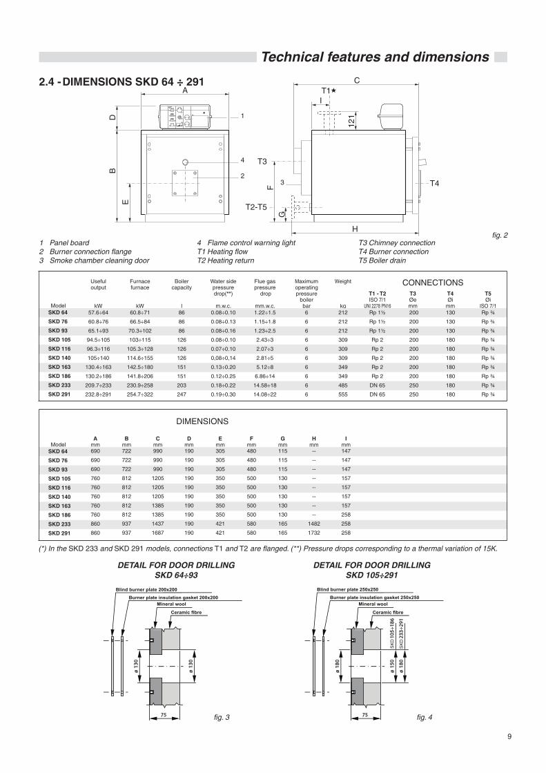
2.4 - DIMENSIONS SKD 64 ÷ 291
1 Panel board2 Burner connection flange3 Smoke chamber cleaning door
4 Flame control warning light T1 Heating flowT2 Heating return
T3 Chimney connectionT4 Burner connectionT5 Boiler drain
fig. 2
(*) In the SKD 233 and SKD 291 models, connections T1 and T2 are flanged. (**) Pressure drops corresponding to a thermal variation of 15K.
200
200
200
200
200
200
200
200
250
250
130
130
130
180
180
180
180
180
180
180
Rp ¾
Rp ¾
Rp ¾
Rp ¾
Rp ¾
Rp ¾
Rp ¾
Rp ¾
Rp ¾
Rp ¾
86
86
86
126
126
126
151
151
203
247
0.08÷0.10
0.08÷0.13
0.08÷0.16
0.08÷0.10
0.07÷0.10
0,08÷0,14
0.13÷0.20
0.12÷0.25
0.18÷0.22
0.19÷0.30
1.22÷1.5
1.15÷1.8
1.23÷2.5
2.43÷3
2.07÷3
2.81÷5
5.12÷8
6.86÷14
14.58÷18
14.08÷22
6
6
6
6
6
6
6
6
6
6
Rp 1½
Rp 1½
Rp 1½
Rp 2
Rp 2
Rp 2
Rp 2
Rp 2
DN 65
DN 65
60.8÷71
66.5÷84
70.3÷102
103÷115
105.3÷128
114.6÷155
142.5÷180
141.8÷206
230.9÷258
254.7÷322
212
212
212
309
309
309
349
349
485
555
Useful output
kWModel
Model
Furnacefurnace
kW
Boilercapacity
l
Water sidepressuredrop(**)
m.w.c.
Flue gaspressure
drop
mm.w.c.
Maximumoperatingpressure
boilerbar
CONNECTIONST1 - T2ISO 7/1
UNI 2278 PN16
T3Øemm
T4Øi
mm
T5Øi
ISO 7/1
DIMENSIONS
Amm690
690
690
760
760
760
760
760
860
860
Bmm722
722
722
812
812
812
812
812
937
937
990
990
990
1205
1205
1205
1385
1385
1437
1687
Cmm
190
190
190
190
190
190
190
190
190
190
Dmm
305
305
305
350
350
350
350
350
421
421
Emm
Fmm480
480
480
500
500
500
500
500
580
580
Gmm115
115
115
130
130
130
130
130
165
165
Hmm--
--
--
--
--
--
--
--
1482
1732
DETAIL FOR DOOR DRILLINGSKD 64÷93
DETAIL FOR DOOR DRILLINGSKD 105÷291
fig. 3 fig. 4
L ana di rocc ia
F ibra ceramic a
P ias tra porta-bruc iatore c ieca 200x200
G uarnizione pias tra porta-bruc iatore 200x200
ø 1
30
ø 1
30
75
L ana di rocc ia
F ibra ceramica
P ias tra porta-bruc iatore c ieca 250x250
G uarnizione pias tra porta-bruc iatore 250x250
ø 1
80
ø 1
50
75
ø 1
80
MD
105
÷186
MD
233
÷291
Imm147
147
147
157
157
157
157
258
258
258
SKD 64
SKD 76
SKD 93
SKD 105
SKD 116
SKD 140
SKD 163
SKD 186
SKD 233
SKD 291
SK
D
SK
D
Blind burner plate 200x200Burner plate insulation gasket 200x200
Mineral wool
Ceramic fibre
Blind burner plate 250x250
Burner plate insulation gasket 250x250Mineral wool
Ceramic fibre
10
Technical features and dimensions
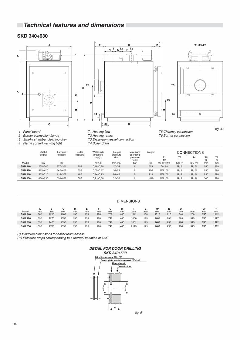
SKD 340÷630
1 Panel board2 Burner connection flange3 Smoke chamber cleaning door4 Flame control warning light
T1 Heating flowT2 Heating returnT3 Expansion vessel connectionT4 Boiler drain
T5 Chimney connectionT6 Burner connection
DETAIL FOR DOOR DRILLINGSKD 340÷630
Useful output
kW255÷340
315÷420
385÷510
480÷630
CONNECTIONST1T2
UNI 2278 PN16
T3
ISO 7/1
T4
ISO 7/1
T5Øi
mm
T6Ø
mmDN 80
DN 100
DN 100
DN 100
Rp 2
Rp 2
Rp 2
Rp 2
Rp ¾
Rp ¾
Rp ¾
Rp ¾
250
250
250
300
220
220
220
220
SKD 340
SKD 420
SKD 510
SKD 630
Furnacefurnace
kW277÷371
342÷459
418÷557
520÷688
Boilercapacity
l298
398
462
565
Water sidepressuredrop(**)
m.w.c.0,16÷0,28
0.09÷0.17
0.14÷0.25
0,21÷0,38
17÷34
16÷29
24÷43
32÷55
Flue gaspressure
drop
mm.w.c.
Maximumoperatingpressure
boilerbar6
6
6
6
Weight
kg629
796
919
1049
SKD 340
SKD 420
SKD 510
SKD 630
DIMENSIONS
Amm860
890
890
890
Bmm
1210
1275
1470
1780
1182
1352
1352
1352
Cmm
190
190
190
190
Dmm
139
139
139
139
Emm
Fmm190
190
190
190
Gmm708
748
748
748
Hmm400
440
440
440
Imm
1541
1606
1801
2113
Lmm130
125
125
125
1310
1485
1485
1485
M*mm
215
255
255
255
Nmm
340
285
480
790
Omm
250
315
315
315
Pmm
750
780
780
780
Q*mm
1112
1177
1372
1682
R*mm
(*) Minimum dimensions for boiler room access.(**) Pressure drops corresponding to a thermal variation of 15K.
fig. 4.1
fig. 5
Lana di rocciaFibra ceramica
Piastra porta-bruciatore cieca 280x280Guarnizione piastra porta-bruciatore 280x280
ø 22
0
ø 22
0
95
Model
Model
Blind burner plate 280x280Burner plate insulation gasket 280x280
Mineral woolCeramic fibre
11
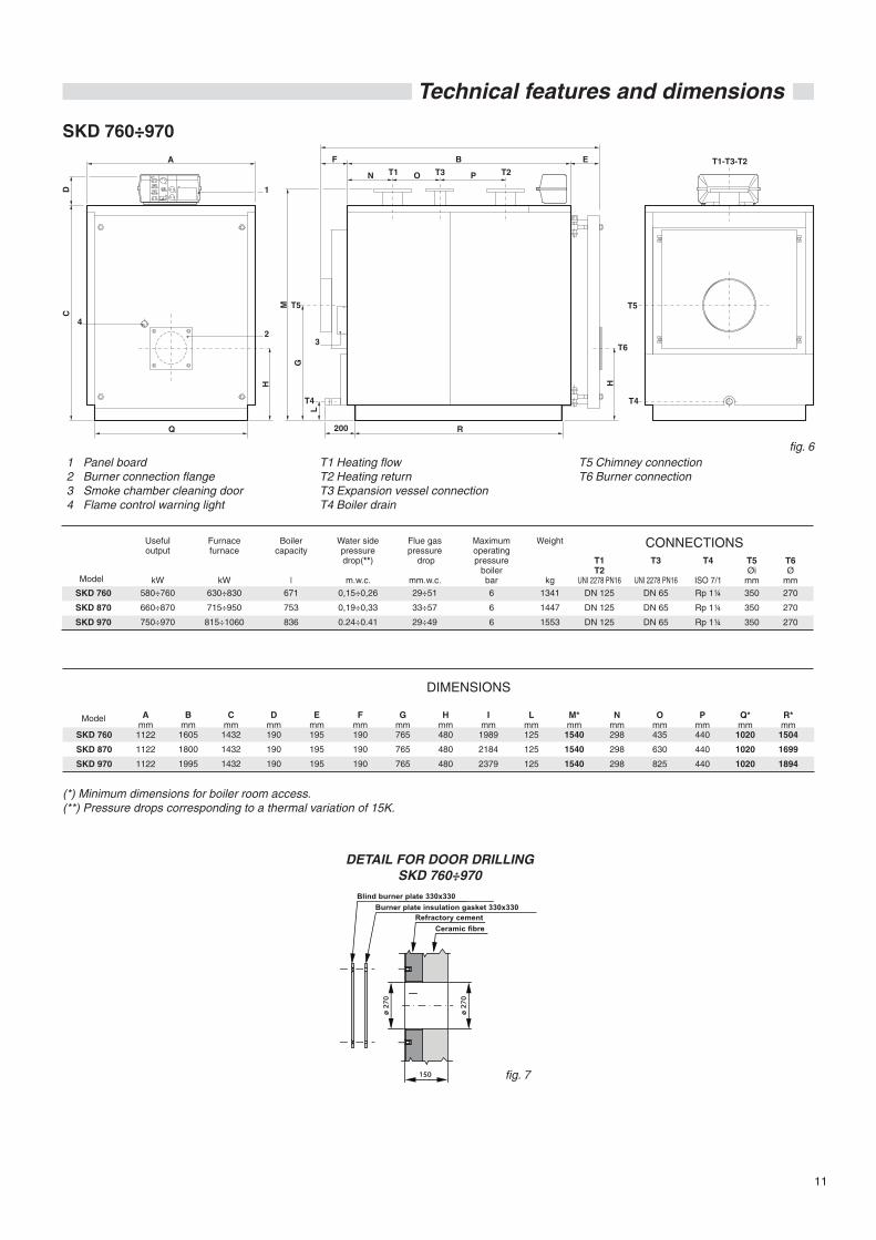
Technical features and dimensions
(*) Minimum dimensions for boiler room access.(**) Pressure drops corresponding to a thermal variation of 15K.
1 Panel board2 Burner connection flange3 Smoke chamber cleaning door4 Flame control warning light
T1 Heating flowT2 Heating returnT3 Expansion vessel connectionT4 Boiler drain
T5 Chimney connectionT6 Burner connection
DETAIL FOR DOOR DRILLINGSKD 760÷970
SKD 760
SKD 870
SKD 970
DIMENSIONS
Amm
1122
1122
1122
Bmm
1605
1800
1995
1432
1432
1432
Cmm
190
190
190
Dmm
195
195
195
Emm
Fmm190
190
190
Gmm765
765
765
Hmm480
480
480
Imm
1989
2184
2379
Lmm125
125
125
1540
1540
1540
M*mm
298
298
298
Nmm
435
630
825
Omm
440
440
440
Pmm
1020
1020
1020
Q*mm
1504
1699
1894
R*mm
Useful output
kW580÷760
660÷870
750÷970
CONNECTIONST1T2
UNI 2278 PN16
T3
UNI 2278 PN16
T4
ISO 7/1
T5Øi
mm
T6Ø
mmDN 125
DN 125
DN 125
DN 65
DN 65
DN 65
Rp 1¼
Rp 1¼
Rp 1¼
350
350
350
270
270
270
SKD 760
SKD 870
SKD 970
Furnacefurnace
kW630÷830
715÷950
815÷1060
Boilercapacity
l671
753
836
Water sidepressuredrop(**)
m.w.c.0,15÷0,26
0,19÷0,33
0.24÷0.41
29÷51
33÷57
29÷49
Flue gaspressure
drop
mm.w.c.
Maximumoperatingpressure
boilerbar6
6
6
Weight
kg1341
1447
1553
SKD 760÷970
fig. 6
fig. 7
˘˘˘?˘˘˘˘˘
F ibra ceramica
P ias tra porta-bruc iatore c ieca 330x330
G uarnizione pias tra porta-bruc iatore 330x330
ø 2
70
ø 2
70
150
Model
Model
Blind burner plate 330x330Burner plate insulation gasket 330x330
Refractory cementCeramic fibre
12
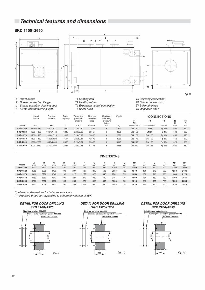
Technical features and dimensions
T1 Heating flowT2 Heating returnT3 Expansion vessel connectionT4 Boiler drain
T5 Chimney connectionT6 Burner connectionT7 Boiler air bleedT8 Inspection door
(*) Minimum dimensions for boiler room access.(**) Pressure drops corresponding to a thermal variation of 15K.
SKD 1100÷2650
SKD 1100
SKD 1320
SKD 1570
SKD 1850
SKD 2200
SKD 2650
SKD 1100
SKD 1320
SKD 1570
SKD 1850
SKD 2200
SKD 2650
DIMENSIONS
Amm
1352
1352
1462
1462
1622
1622
Bmm
1952
2292
2282
2652
2692
3014
1432
1432
1542
1542
1702
1702
Cmm
190
190
190
190
190
190
Dmm
207
207
227
227
259
258
Emm
Fmm187
187
272
272
274
273
Gmm810
810
880
880
950
950
Hmm595
595
640
640
690
690
Imm
2346
2686
2781
3151
3225
3545
Lmm180
180
75
75
75
75
1540
1540
1650
1650
1810
1810
M*mm
461
461
561
561
661
662
Nmm
330
670
510
880
670
990
Omm
500
500
550
550
700
700
Pmm
1250
1250
1360
1360
1520
1520
Q*mm
1846
2186
2176
2546
2590
2910
R*mm
DETAIL FOR DOOR DRILLINGSKD 1100÷1320
DETAIL FOR DOOR DRILLINGSKD 2200÷2650
DETAIL FOR DOOR DRILLINGSKD 1570÷1850
Useful output
kW
860÷1100
1000÷1320
1200÷1570
1400÷1850
1700÷2200
2000÷2650
Furnacefurnace
kW
935÷1200
1087÷1442
1304÷1715
1520÷2020
1845÷2400
2170÷2890
Boilercapacity
l
1040
1242
1418
1617
2086
2324
Water sidepressuredrop(**)
m.w.c.
0.18÷0.30
0.20÷0.35
0,19÷0,33
0.26÷0.45
0.21÷0.34
0.28÷0.48
1 Panel board2 Burner connection flange3 Smoke chamber cleaning door4 Flame control warning light
Flue gaspressure
drop
mm.w.c.
32÷52
38÷67
35÷60
42÷73
39÷65
43÷76
Maximumoperatingpressure
boilerbar
6
6
6
6
6
6
Weight
kg
1821
2030
2780
3280
4145
4465
CONNECTIONST1T2
UNI 2278 PN16
T3
UNI 2278 PN16
DN 80
DN 80
DN 100
DN 100
DN 125
DN 125
DN 150
DN 150
DN 175
DN 175
DN 200
DN 200
T4
ISO 7/1
Rp 1½
Rp 1½
Rp 1½
Rp 1½
Rp 1½
Rp 1½
T5Øi
mm
400
400
450
450
520
520
T6Ø
mm
320
320
320
320
380
380
fig. 8
˘˘˘?˘˘˘˘˘
P ias tra porta-bruc iatore c ieca 380x380
G uarnizione pias tra porta-bruc iatore 380x380
ø 3
20
ø 3
20
160
˘˘˘?˘˘˘˘˘
P ias tra porta-bruc iatore c ieca 380x380
G uarnizione pias tra porta-bruc iatore 380x380
ø 3
20
ø 3
20
180
˘˘˘?˘˘˘˘˘
P ias tra porta-bruc iatore c ieca 450x450
G uarnizione pias tra porta-bruc iatore 450x450
ø 3
80
ø 3
80
190fig. 9 fig. 10 fig. 11
Model
Model
Blind burner plate 380x380 Blind burner plate 380x380 Blind burner plate 450x450Burner plate insulation gasket 380x380 Burner plate insulation gasket 380x380 Burner plate insulation gasket 450x450
Refractory cement Refractory cement Refractory cement
13
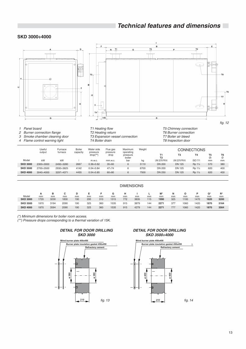
Technical features and dimensions
T1 Heating flowT2 Heating returnT3 Expansion vessel connectionT4 Boiler drain
T5 Chimney connectionT6 Burner connectionT7 Boiler air bleedT8 Inspection door
(*) Minimum dimensions for boiler room access.(**) Pressure drops corresponding to a thermal variation of 15K.
SKD 3000÷4000
SKD 3000
SKD 3500
SKD 4000
SKD 3000
SKD 3500
SKD 4000
DIMENSIONS
Amm
1720
1970
1970
Bmm
3230
3194
3594
1830
2090
2090
Cmm
190
190
190
Dmm
295
325
325
Emm
Fmm310
360
360
Gmm
1315
1535
1535
Hmm772
915
915
Imm
3835
3879
4279
Lmm115
144
144
1990
2271
2271
M*mm
325
377
777
Nmm
1100
1060
1060
Omm
1470
1420
1420
Pmm
1620
1870
1870
Q*mm
3200
3164
3564
R*mm
Useful output
kW
2300÷3000
2700÷3500
3040÷4000
Furnacefurnace
kW
2492÷3280
2930÷3825
3297÷4371
Boilercapacity
l
2667
4142
4455
Water sidepressuredrop(**)
m.w.c.
0.36÷0.62
0.54÷0.84
0.54÷0.85
1 Panel board2 Burner connection flange3 Smoke chamber cleaning door4 Flame control warning light
Flue gaspressure
drop
mm.w.c.
35÷60
47÷74
60÷80
Maximumoperatingpressure
boilerbar
6
6
6
Weight
kg
5110
6700
7500
CONNECTIONST1T2
UNI 2278 PN16
T3
UNI 2278 PN16
DN 125
DN 125
DN 125
DN 200
DN 200
DN 250
T4
ISO 7/1
Rp 1½
Rp 1½
Rp 1½
T5Øi
mm
570
620
620
T6Ø
mm
380
400
400
DETAIL FOR DOOR DRILLINGSKD 3000
DETAIL FOR DOOR DRILLINGSKD 3500÷4000
˘˘˘?˘˘˘˘˘
P ias tra porta-bruc iatore c ieca 450x450
G uarnizione pias tra porta-bruc iatore 450x450
ø 4
00
ø 4
00
210
fig. 12
fig. 13 fig. 14
˘˘˘?˘˘˘˘˘
P ias tra porta-bruc iatore c ieca 450x450
G uarnizione pias tra porta-bruc iatore 450x450
ø 3
80
ø 3
80
210
Model
Model
Blind burner plate 450x450 Blind burner plate 450x450Burner plate insulation gasket 450x450 Burner plate insulation gasket 450x450
Refractory cement Refractory cement
14
Technical features and dimensions
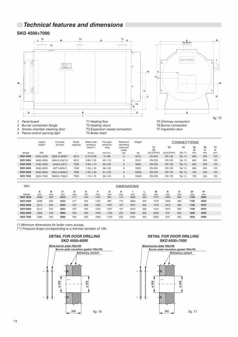
(*) Minimum dimensions for boiler room access.(**) Pressure drops corresponding to a thermal variation of 15K.
SKD 4500÷7000
fig. 15 T1 Heating flowT2 Heating returnT3 Expansion vessel connectionT4 Boiler drain
T5 Chimney connectionT6 Burner connectionT7 Inspection door
1 Panel board2 Burner connection flange3 Smoke chamber cleaning door4 Flame control warning light
SKD
ModelSKD 4500
SKD 5000
SKD 5500
SKD 6000
SKD 6500
SKD 7000
DIMENSIONSA
mm2088
2088
2214
2214
2380
2380
Bmm226
226
240
240
240
240
2533
2533
2653
2653
2860
2860
C*mm
417
417
437
437
509
509
Dmm
445
445
465
465
595
595
Emm
Fmm
1437
1437
1550
1550
1650
1650
Gmm987
987
1007
1007
1100
1100
Hmm170
170
167
167
224
224
Imm
4682
4682
4872
4872
5484
5484
Lmm320
320
320
320
325
325
1475
1475
1475
1475
2920
2920
Mmm
1665
1665
1815
1815
670
670
Nmm
360
360
360
360
465
465
Omm
1700
1700
1700
1700
1850
1850
Q*mm
R*mm
Useful output
kW
3420÷4500
3800÷5000
4180÷5500
4560÷6000
4940÷6500
5320÷7000
Furnacefurnace
kW
3638.3÷4838.7
4064.2÷5421.8
4446.8÷5914
4877÷6506.2
5255.3÷6989.2
5689.8÷7590.5
Boilercapacity
l
6012
6012
7058
7058
7909
7909
Water sidepressuredrop(**)
m.w.c.
0.70÷0.85
0.80÷1.05
0.95÷1.15
1.00÷1.35
1.05÷1.50
1.10÷1.75
Flue gaspressure
drop
mm.w.c.
51÷88
65÷110
60÷100
68÷120
61÷105
69÷120
Maximumoperatingpressure
boilerbar
6
6
6
6
6
6
Weight
kg
8310
8310
9300
9300
12600
12600
CONNECTIONST1T2
UNI 2278 PN16
T3
UNI 2278 PN16
DN 125
DN 125
DN 125
DN 125
DN 125
DN 125
DN 250
DN 250
DN 250
DN 250
DN 250
DN 250
T4
ISO 7/1
Rp 1½
Rp 1½
Rp 1½
Rp 1½
Rp 1½
Rp 1½
T5Øi
mm
660
660
660
660
720
720
T6Ø
mm
500
500
500
500
500
500
T7Ø
mm
133
133
133
133
133
133
3820
3820
3970
3970
4380
4380
fig. 16
˘˘˘?˘˘˘˘˘
P ias tra porta-bruc iatore c iec a 700x700
G uarnizione pias tra porta-bruc iatore 700x700
ø 5
00
ø 5
00
240
DETAIL FOR DOOR DRILLINGSKD 4500÷6000
SKD 4500
SKD 5000
SKD 5500
SKD 6000
SKD 6500
SKD 7000
DETAIL FOR DOOR DRILLINGSKD 6500÷7000
˘˘˘?˘˘˘˘˘
P ias tra porta-bruc iatore c iec a 700x700
G uarnizione pias tra porta-bruc iatore 700x700
ø 5
00
ø 5
00
282 fig. 17
Model
Blind burner plate 700x700 Blind burner plate 700x700Burner plate insulation gasket 700x700 Burner plate insulation gasket 700x700
Refractory cement Refractory cement
15
Technical features and dimensions2.
4 - O
PE
RA
TIN
G D
ATA
AC
CO
RD
ING
TO
UN
I 103
48 S
KD
64
÷ 29
1
Nom
inal
hea
t out
put
The
rmal
out
put o
f fur
nace
Hea
t effi
cien
cy a
t nom
inal
load
(10
0%)
Hea
t effi
cien
cy a
t 30%
load
Num
ber
of s
tars
(ac
cord
ing
to 9
2/42
EE
C)
Com
bust
ion
effic
ienc
y at
nom
inal
load
(10
0%)
Hea
t los
s at
cas
ing
(min
.-m
ax.)
Hea
t los
s at
chi
mne
y w
ith b
urne
r on
(m
in.-
max
.)
Hea
t los
s at
chi
mne
y w
ith b
urne
r of
f (m
in.-
max
.)
Gas
-fire
d
Flu
e ga
s te
mpe
ratu
re tf
-ta
(min
.-m
ax.)
CO
2 co
nten
t
Flu
e ga
s m
ass
flow
rat
e (m
in.-
max
)
Die
sel o
il-fi
red
Flu
e ga
s te
mpe
ratu
re tf
-ta
(min
.-m
ax.)
CO
2 co
nten
t
Flu
e ga
s m
ass
flow
rat
e (m
in.-
max
)
SK
D 1
63
130.
4÷16
3.0
142.
5÷18
0.0
91.5
÷90.
5
91.2
÷90.
2
1
92.1
÷91.
2
0,6÷
0,6
7.8÷
8.7
0,2÷
0,2
160.
5÷17
9.5
9.8¸
9.8
214.
1÷27
0.6
171.
7÷19
2.0
12.8
÷12.
8
218.
2÷27
5.6
SK
D 1
86
130.
2÷18
6.0
141.
8÷20
6.0
91.8
÷90.
2
91.5
÷90.
0
1
92.4
÷91.
0
0,6÷
0,7
7.5÷
8.9
0,2÷
0,2
154.
1÷18
4.2
9,8÷
9,8
231.
2÷30
9.6
164.
8÷19
7.0
12.8
÷12.
8
275.
6÷21
7.2
SK
D 2
33
209.
7÷23
3.0
230.
9÷25
8.0
90.8
÷90.
3
90.5
÷90.
0
1
91.5
÷91.
0
0.7÷
0.7
8.4÷
8.9
0,2÷
0,2
173.
8÷18
3.2
9,8÷
9,8
247.
1÷38
7.8
185.
9÷19
6.0
12.8
÷12.
8
315.
4÷35
3.6
SK
D 2
91
232.
8÷29
1.0
254.
7÷32
2.0
91.3
÷90.
3
91.1
÷90.
1
1
91.8
÷90.
8
0.4÷
0.5
8.1÷
9.1
0,2÷
0,2
167.
2÷18
7.0
9,8÷
9,8
382.
9÷48
4.0
178.
8÷20
0.0
12.8
÷12.
8
390.
1÷49
3.1
kW kW % % no.
% % % % °C % kg/h
°C % kg/h
SK
D 9
3
65.1
÷93.
0
70.3
÷102
.0
92.5
÷91.
1
92.3
÷90.
9
1
93.0
÷91.
6
0.4÷
0.5
6.9÷
8.3
0,2÷
0,2
141.
4÷16
9.2
9.7÷
9.7
106.
6÷15
4.7
151.
4÷18
1.0
12.6
÷12.
6
109.
3÷15
8.6
SK
D 1
05
94.5
÷105
.0
103.
0÷11
5.0
91.7
÷91.
3
91.5
÷91.
0
1
92.2
÷91.
8
0.4÷
0.5
7.7÷
8.1
0,2÷
0,2
158.
7÷16
7.3
9.8÷
9.7
154.
7÷17
2.9
169.
8÷17
9.0
12.7
÷12.
7
158.
9÷17
7.4
SK
D 1
16
96.6
÷116
.0
105.
3÷12
8.0
91.4
÷90.
6
91.1
÷91.
3
1
91.9
÷91.
1
0.4÷
0.4
8.1÷
8.9
0,2÷
0,2
166.
1÷18
2.3
9,8÷
9,8
158.
2÷19
2.4
177.
6÷19
5.0
12.8
÷12.
8
161.
2÷19
6.0
SK
D 1
40
105.
0÷14
0.0
114.
6÷15
5.0
91.6
÷90.
3
91.3
÷90.
0
1
92.0
÷90.
8
0.4÷
0.5
7.9÷
9.1
0,2÷
0,2
162.
7÷18
7.9
9,8÷
9,8
172.
3÷23
3.0
174.
0÷20
1.0
12.8
÷12.
8
175.
5÷23
7.4
SK
D 7
6
60.8
÷76.
0
66.5
÷84.
0
91.4
÷90.
4
91.2
÷90.
2
1
91.9
÷91.
0
0,5÷
0,5
8.0÷
8.9
0,2÷
0,2
161.
4÷18
0.4
9.6÷
9.6
101÷
128.
5
172.
6÷19
3.0
12.5
÷12.
5
104.
2÷13
1.6
SK
D 6
4
57.6
÷64
.0
63.5
÷71.
0
90.6
÷90.
1
90.4
÷89.
8
1
91.1
÷90.
6
0,5÷
0,5
8.8÷
9.3
0,2÷
0,2
177.
4÷18
7.0
9.5÷
9.5
97.6
÷109
.0
189.
7÷20
0.0
12.4
÷12.
4
99.7
÷111
.4
OP
ER
AT
ING
DA
TA A
CC
OR
DIN
G T
O U
NI 1
0348
SK
D 3
40 ÷
132
0
Nom
inal
hea
t out
put
The
rmal
out
put o
f fur
nace
Hea
t effi
cien
cy a
t nom
inal
load
(10
0%)
Hea
t effi
cien
cy a
t 30%
load
Num
ber
of s
tars
(ac
cord
ing
to 9
2/42
EE
C)
Com
bust
ion
effic
ienc
y at
nom
inal
load
(10
0%)
Hea
t los
s at
cas
ing
(min
.-m
ax.)
Hea
t los
s at
chi
mne
y w
ith b
urne
r on
(m
in.-
max
.)
Hea
t los
s at
chi
mne
y w
ith b
urne
r of
f (m
in.-
max
.)
Gas
-fire
d
Flu
e ga
s te
mpe
ratu
re tf
-ta
(min
.-m
ax.)
CO
2 co
nten
t
Flu
e ga
s m
ass
flow
rat
e (m
in.-
max
)
Die
sel o
il-fi
red
Flu
e ga
s te
mpe
ratu
re tf
-ta
(min
.-m
ax.)
CO
2 co
nten
t
Flu
e ga
s m
ass
flow
rat
e (m
in.-
max
)
SK
D 9
70
750.
0÷97
0
815.
0÷10
60
92.0
÷91.
5
93.9
÷93.
9
1
91.5
÷92.
4
0.5÷
0.4
7.4÷
8.0
0,2÷
0,2
160.
5÷17
9.5
9.8¸
9.8
1225
.1÷1
593.
3
158.
0÷17
2.0
12.8
÷12.
8
1094
.9÷1
454.
7
SK
D 1
100
860.
0÷11
10
935.
0÷12
00
91.8
÷91.
6
93.9
÷93.
9
1
92.4
÷92.
0
0.4÷
0.3
7.6÷
7.9
0,2÷
0,2
154.
1÷18
4.2
9,8÷
9,8
1405
.4÷1
803.
8
164.
0÷17
7.0
12.8
÷12.
8
1248
÷162
3.2
SK
D 1
320
1000
.0÷1
320
1087
.0÷1
442
92.0
÷91.
5
93.9
÷93.
9
1
92.2
÷91.
8
0.2÷
0.3
7.7÷
8.1
0,2÷
0,2
173.
8÷18
3.2
9,8÷
9,8
1633
.9÷2
167.
5
170.
0÷17
9.0
12.8
÷12.
8
1664
.5÷2
208.
1
kW kW % % no.
% % % % °C % kg/h
°C % kg/h
SK
D 5
10
385.
0÷51
0
418.
0÷55
7
92.1
÷91.
5
93.9
÷93.
9
1
92.7
÷92.
4
0.6÷
0.9
7.2÷
7.5
0,2÷
0,2
141.
4÷16
9.2
9,8÷
9,8
628.
3÷83
7.3
160.
0÷16
5.0
12.6
÷12.
6
640.
1÷85
2.9
SK
D 6
30
480.
0÷63
0
520.
0÷68
8
92.3
÷91.
5
93.9
÷93.
9
1
92.6
÷92.
4
0.3÷
0.4
7.3÷
7.9
0,2÷
0,2
158.
7÷16
7.3
9,8÷
9,8
781.
6÷10
34.2
169.
8÷17
9.0
12.7
÷12.
7
158.
9÷17
7.4
SK
D 7
60
580.
0÷77
6
630.
0÷83
0
92.0
÷91.
5
93.9
÷93.
9
1
92.3
÷92.
1
0.2÷
0.5
7.6÷
7.8
0,2÷
0,2
166.
1÷18
2.3
9,8÷
9,8
947.
0÷12
47.6
162.
0÷17
5.0
12.8
÷12.
8
796.
3÷10
53.5
SK
D 8
70
660.
0÷87
0
715.
0÷95
0
92.3
÷91.
5
93.9
÷93.
9
1
92.8
÷92.
1
0,5÷
0,6
7.1÷
7.8
0,2÷
0,2
162.
7÷18
7.9
9,8÷
9,8
1074
.7÷1
428
168.
0÷17
3,0
12.8
÷12.
8
964.
7÷12
71.0
SK
D 4
20
315.
0÷42
0
342.
0÷45
9
92.1
÷91.
5
93.9
÷93.
9
1
92.8
÷92.
4
0.7÷
0.9
7.1÷
7.5
0,2÷
0,2
147.
3÷15
4.8
9,8÷
9,8
514.
1÷68
9.9
158.
0÷16
6.0
12.5
÷12.
5
523.
7÷70
2.9
SK
D 3
40
255.
0÷34
0
277.
0÷37
1W
92.0
÷91.
6
93.6
÷93.
6
1
92.9
÷92.
5
0.8÷
0.8
7.1÷
7.4
0,2÷
0,2
145.
4÷15
2.9
9,8÷
9,8
416.
4÷55
7.7
156.
0÷16
4.0
12.8
÷12.
8
424.
2÷56
8.1
16
Technical features and dimensions
OP
ER
AT
ING
DA
TA A
CC
OR
DIN
G T
O U
NI 1
0348
SK
D 5
500
÷ 70
00
Nom
inal
hea
t out
put
The
rmal
out
put o
f fur
nace
Hea
t effi
cien
cy a
t nom
inal
load
(10
0%)
Hea
t effi
cien
cy a
t 30%
load
Num
ber
of s
tars
(ac
cord
ing
to 9
2/42
EE
C)
Com
bust
ion
effic
ienc
y at
nom
inal
load
(10
0%)
Hea
t los
s at
cas
ing
(min
.-m
ax.)
Hea
t los
s at
chi
mne
y w
ith b
urne
r on
(m
in.-
max
.)
Hea
t los
s at
chi
mne
y w
ith b
urne
r of
f (m
in.-
max
.)
Gas
-fire
d
Flu
e ga
s te
mpe
ratu
re tf
-ta
(min
.-m
ax.)
CO
2 co
nten
t
Flu
e ga
s m
ass
flow
rat
e (m
in.-
max
)
Die
sel o
il-fi
red
Flu
e ga
s te
mpe
ratu
re tf
-ta
(min
.-m
ax.)
CO
2 co
nten
t
Flu
e ga
s m
ass
flow
rat
e (m
in.-
max
)
SK
D 4
000
3040
÷400
0
3297
÷437
1
92.2
÷91.
5
93.9
÷93.
9
1
91.4
÷92.
8
0.5÷
0.4
7.4÷
8.0
0.2÷
0.3
153.
8÷16
6.9
9.8¸
9.8
5754
.0÷4
955.
9
165.
0÷17
9.0
12.8
÷12.
8
5048
.7÷6
693.
3
SK
D 4
500
3800
÷500
0
3638
÷433
8
94.0
÷93.
0
94.6
÷93.
6
1
94.5
÷93.
5
0.4÷
0.3
7.6÷
7.9
0,5÷
0,5
112÷
133
9,8÷
9,8
6570
.2÷5
468.
9
120.
0÷14
3.0
12.8
÷12.
8
5571
.4÷7
409.
6
SK
D 5
000
4180
÷550
0
4064
.2÷5
421.
8
93.5
÷92.
2
94.1
÷92.
8
1
94.0
÷92.
8
0.2÷
0.3
7.7÷
8.1
0,5÷
0,6
122÷
147
9,8÷
9,8
6109
÷814
9.8
130.
0÷15
7.0
12.8
÷12.
8
6223
.5÷8
302.
5
kW kW % % no.
% % % % °C % kg/h
°C % kg/h
SK
D 2
200
1700
÷220
0
1845
÷240
0
92.1
÷91.
6
93.9
÷93.
9
1
92.4
÷91.
9
0.3÷
0.3
7.2÷
7.5
0,2÷
0,2
153.
8÷16
4.1
9,8÷
9,8
2773
.3÷3
607.
5
165÷
176.
0
12.8
÷12.
8
2825
.3÷3
675.
1
SK
D 2
650
2000
÷265
0
2170
÷289
0
92.1
÷91.
7
93.9
÷93.
9
1
92.4
÷92.
0
0.3÷
0.3
7.3÷
7.9
0,2÷
0,2
153.
8÷16
3.2
9,8÷
9,8
3261
.8÷4
344.
1
165÷
175.
0
12.8
÷12.
8
3322
.9÷4
425.
5
SK
D 3
000
2300
÷300
0
2492
÷328
0
92.3
÷91.
4
93.9
÷93.
9
1
92.4
÷91.
8
0.2÷
0.3
7.6÷
7.8
0,2÷
0,2
153.
8÷16
7.8
9,8÷
9,8
3745
.8÷4
930.
3
165.
0÷18
0.0
12.8
÷12.
8
3816
÷502
2.7
SK
D 3
500
2700
÷350
0
2930
÷382
8
92.1
÷91.
4
93.9
÷93.
9
1
92.4
÷91.
8
0.3÷
0.3
7.1÷
7.8
0,2÷
0,2
153.
8÷16
7.8
9,8÷
9,8
4404
.2÷5
754
165.
0÷18
0.0
12.8
÷12.
8
4486
.7÷4
486.
7
SK
D 1
850
1400
÷185
0
1520
÷202
0
92.1
÷91.
5
93.9
÷93.
9
1
92.4
÷91.
9
0.3÷
0.3
7.1÷
7.5
0,2÷
0,2
153.
8÷16
6.0
9,8÷
9,8
2284
.8÷3
036.
3
165÷
178.
0
12.8
÷12.
8
2327
.6÷3
093.
2
SK
D 1
570
1200
÷157
0.0
1304
÷171
5.0
92.0
÷91.
5
93.9
÷93.
9
1
92.2
÷91.
9
0.2÷
0.4
7.7÷
8.0
0,2÷
0,2
167.
2÷18
7.0
9,8÷
9,8
1960
.1÷2
577.
9
170.
0÷17
7.0
12.8
÷12.
8
1996
.8÷2
626.
2
Nom
inal
hea
t out
put
The
rmal
out
put o
f fur
nace
Hea
t effi
cien
cy a
t nom
inal
load
(10
0%)
Hea
t effi
cien
cy a
t 30%
load
Num
ber
of s
tars
(ac
cord
ing
to 9
2/42
EE
C)
Com
bust
ion
effic
ienc
y at
nom
inal
load
(10
0%)
Hea
t los
s at
cas
ing
(min
.-m
ax.)
Hea
t los
s at
chi
mne
y w
ith b
urne
r on
(m
in.-
max
.)
Hea
t los
s at
chi
mne
y w
ith b
urne
r of
f (m
in.-
max
.)
Gas
-fire
d
Flu
e ga
s te
mpe
ratu
re tf
-ta
(min
.-m
ax.)
CO
2 co
nten
t
Flu
e ga
s m
ass
flow
rat
e (m
in.-
max
)
Die
sel o
il-fi
red
Flu
e ga
s te
mpe
ratu
re tf
-ta
(min
.-m
ax.)
CO
2 co
nten
t
Flu
e ga
s m
ass
flow
rat
e (m
in.-
max
)
kW kW % % no.
% % % % °C % kg/h
°C % kg/h
SK
D 6
500
4940
÷650
0
5255
.3÷6
989.
2
94.0
÷93.
0
94.6
÷93.
6
2
92.4
÷91.
9
0.5÷
0.4
5.4÷
6.5
0,2÷
0,2
112.
0÷13
4.0
9,8÷
9,8
7899
.5÷1
0506
120÷
143.
0
12.8
÷12.
8
8047
.5÷1
0702
.7
SK
D 7
000
5320
÷700
0
5689
.8÷7
590.
5
93.5
÷92.
2
94.1
÷92.
8
2
92.4
÷92.
0
0,5÷
0,6
5.9÷
7.1
0,2÷
0,2
122.
0÷14
7.0
9,8÷
9,8
8552
.6÷1
1410
130÷
157.
0
12.8
÷12.
8
8712
.9÷1
1623
.5
SK
D 6
000
4560
÷600
0
4877
÷650
6.2
93.5
÷92.
2
94.1
÷92.
8
2
92.4
÷91.
9
0,5÷
0,6
5.9÷
7.1
0,2÷
0,2
122.
0÷14
7.0
9,8÷
9,8
7730
.8÷9
779.
7
130÷
157.
0
12.8
÷12.
8
7468
.2÷9
963
SK
D 5
500
4180
÷550
0
4446
.8÷5
914
94.0
÷93.
0
94.6
÷93.
6
2
94.5
÷93.
4
0.5÷
0.4
5.4÷
6.5
0,2÷
0,2
112.
0÷13
4.0
9,8÷
9,8
6684
.2÷8
889.
5
120.
0÷14
3.0
12.8
÷12.
8
6809
.4÷9
056.
1
OP
ER
AT
ING
DA
TA A
CC
OR
DIN
G T
O U
NI 1
0348
SK
D 1
570
÷ 50
00
17
Technical features and dimensions
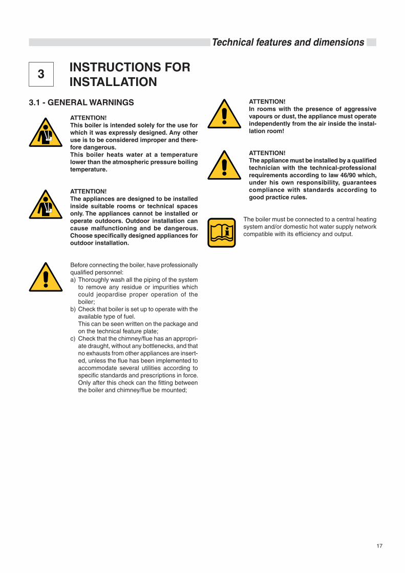
3 INSTRUCTIONS FOR INSTALLATION
3.1 - GENERAL WARNINGS
ATTENTION!This boiler is intended solely for the use for which it was expressly designed. Any other use is to be considered improper and there-fore dangerous.This boiler heats water at a temperature lower than the atmospheric pressure boiling temperature.
ATTENTION! The appliances are designed to be installed inside suitable rooms or technical spaces only. The appliances cannot be installed or operate outdoors. Outdoor installation can cause malfunctioning and be dangerous. Choose specifically designed appliances for outdoor installation.
Before connecting the boiler, have professionally qualified personnel:a) Thoroughly wash all the piping of the system
to remove any residue or impurities which could jeopardise proper operation of the boiler;
b) Check that boiler is set up to operate with the available type of fuel.
This can be seen written on the package and on the technical feature plate;
c) Check that the chimney/flue has an appropri-ate draught, without any bottlenecks, and that no exhausts from other appliances are insert-ed, unless the flue has been implemented to accommodate several utilities according to specific standards and prescriptions in force. Only after this check can the fitting between the boiler and chimney/flue be mounted;
ATTENTION!In rooms with the presence of aggressive vapours or dust, the appliance must operate independently from the air inside the instal-lation room!
ATTENTION!The appliance must be installed by a qualified technician with the technical-professional requirements according to law 46/90 which, under his own responsibility, guarantees compliance with standards according to good practice rules.
The boiler must be connected to a central heating system and/or domestic hot water supply network compatible with its efficiency and output.

18
Installation instructions
3.2 - INSTALLATION STANDARDS
The appliance must be installed in compliance with the instruc-tions provided in this manual.
It must be installed by a professionally qualified technician, who shall assume the responsibility of respecting all local and/or national laws published in the official journal, as well as applicable technical standards.
SKD is a steel boiler which can be combined with air-blown diesel or gas fired burners of category II2H3+.
Contact the gas supplying company before installing the appli-ance (if gas-fired).
The following standards, rules and prescriptions must be ob-served to perform installation. This list is indicative and not complete, needing to follow the progress of the "state-of-the-art".
Standard UNI 7129 Design, installation and maintenance of gas systems for house-hold use supplied by distribution network (NATURAL GAS).
Standard UNI 11137-1 Guidelines for inspection and restoration of the sealing of indoor systems in operation
Standard UNI 7131 Design, installation and maintenance of liquefied petroleum gas (LPG) systems for household use not supplied by distribution network.
Standard UNI 10412 of December 1994.Hot water heating systems. Safety prescriptions.FIELD OF APPLICATION: thermal potentials greater than 35 kW (30,000 kcal/h).
LAW March 5,1990 N° 46 and relative applicative regulation by Italian Presidential Decree 447 of December 6, 1991 (and subsequent amendments).Safety standards for systems FIELD OF APPLICATION: without thermal potential limits.
STANDARD UNI EN 676, November 1998.Air-blown gas-fired burners.Safety prescriptions.
L.D. Num. 93 of February 25, 2000.Implementation of directive 97/23/EC (P.E.D.) concerning pres-surised equipment.FIELD OF APPLICATION: appliances fed by liquid fuels (naph-tha, diesel oil, combustible oil) and solids.
Standard UNI 10847 of March 2000.Single flue systems for generators fed by solid and liquid fuels. Maintenance and control. Guidelines and procedures.
LAW January 9, 1990 N° 10 and relative applicative regulation by Italian Presidential Decree. 412 of 26 August 1993 (and subsequent modifications), Italian Presidential Decree n°551 of 21.12.1999.Regulation with amendments to Italian Presidential Decree. n°
412 concerning design, installation, operation and maintenance of thermal systems in buildings, in order to reduce energy con-sumption.FIELD OF APPLICATION: without thermal potential limits.
Law n°186 of 01.03.1968 Installation standard IEC 64-8 / II ed.Electric systems using rated voltage no greater than 1000 V AC and 1500 V DC.
Installation standard IEC 64-8 / II ed.Electric systems in buildings intended for residential and similar use.
LAW July 13 1966 Num. 615 and relative applicative regulation by Italian Presidential Decree. 1391 of December 22, 1970 (and subsequent amendments).Provisions against environmental pollution (systems fed with solid and liquid fuels).FIELD OF APPLICATION: thermal potentials greater than 35 kW.
Approval art. 44 Community Law of 2001 ''INSTALLATION OF HEAT GENERATORS'' suppression of last period comma 10 DPR551/99, (0.4 m² ventilation).
M.D. 28 April 2005 Approval of the fire prevention technical rule for designing, construction and operation of liquid fuel fed heating systems.FIELD OF APPLICATION: thermal potentials greater than 35 kW.
Directives concerning boiler rooms, building regulations and combustion heating provisions in the country of installation must also be respected.
The appliance must be installed, commissioned and undergo maintenance according to the current "state-of-the-art".This also holds for the hydraulic system, the flue exhaust system and the installation room.
19
Technical features and dimensions
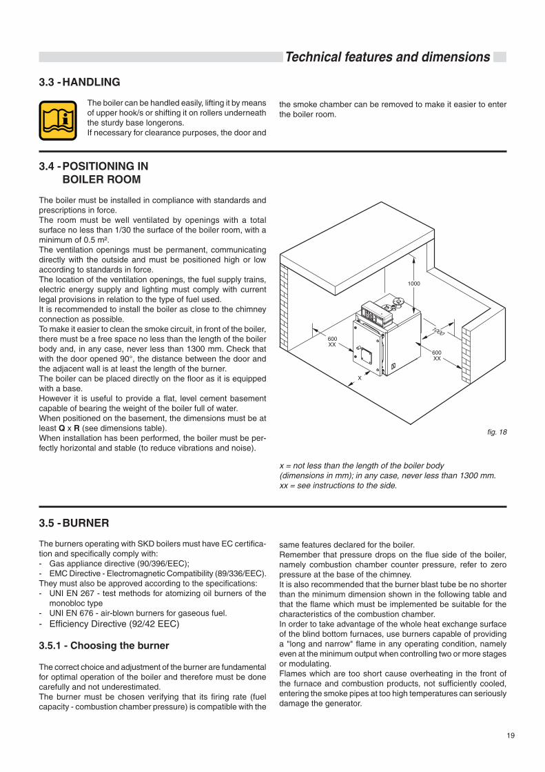
x = not less than the length of the boiler body (dimensions in mm); in any case, never less than 1300 mm.xx = see instructions to the side.
3.4 - POSITIONING IN BOILER ROOM
The boiler must be installed in compliance with standards and prescriptions in force.The room must be well ventilated by openings with a total surface no less than 1/30 the surface of the boiler room, with a minimum of 0.5 m². The ventilation openings must be permanent, communicating directly with the outside and must be positioned high or low according to standards in force. The location of the ventilation openings, the fuel supply trains, electric energy supply and lighting must comply with current legal provisions in relation to the type of fuel used.It is recommended to install the boiler as close to the chimney connection as possible.To make it easier to clean the smoke circuit, in front of the boiler, there must be a free space no less than the length of the boiler body and, in any case, never less than 1300 mm. Check that with the door opened 90°, the distance between the door and the adjacent wall is at least the length of the burner.The boiler can be placed directly on the floor as it is equipped with a base.However it is useful to provide a flat, level cement basement capable of bearing the weight of the boiler full of water.When positioned on the basement, the dimensions must be at least Q x R (see dimensions table).When installation has been performed, the boiler must be per-fectly horizontal and stable (to reduce vibrations and noise).
fig. 18
3.3 - HANDLING
The boiler can be handled easily, lifting it by means of upper hook/s or shifting it on rollers underneath the sturdy base longerons.If necessary for clearance purposes, the door and
3.5 - BURNER
The burners operating with SKD boilers must have EC certifica-tion and specifically comply with:- Gas appliance directive (90/396/EEC);- EMC Directive - Electromagnetic Compatibility (89/336/EEC). They must also be approved according to the specifications:- UNI EN 267 - test methods for atomizing oil burners of the
monobloc type - UNI EN 676 - air-blown burners for gaseous fuel.- Efficiency Directive (92/42 EEC)
3.5.1 - Choosing the burner
The correct choice and adjustment of the burner are fundamental for optimal operation of the boiler and therefore must be done carefully and not underestimated.The burner must be chosen verifying that its firing rate (fuel capacity - combustion chamber pressure) is compatible with the
same features declared for the boiler.Remember that pressure drops on the flue side of the boiler, namely combustion chamber counter pressure, refer to zero pressure at the base of the chimney.It is also recommended that the burner blast tube be no shorter than the minimum dimension shown in the following table and that the flame which must be implemented be suitable for the characteristics of the combustion chamber.In order to take advantage of the whole heat exchange surface of the blind bottom furnaces, use burners capable of providing a "long and narrow" flame in any operating condition, namely even at the minimum output when controlling two or more stages or modulating.Flames which are too short cause overheating in the front of the furnace and combustion products, not sufficiently cooled, entering the smoke pipes at too high temperatures can seriously damage the generator.
the smoke chamber can be removed to make it easier to enter the boiler room.
20
Installation instructions
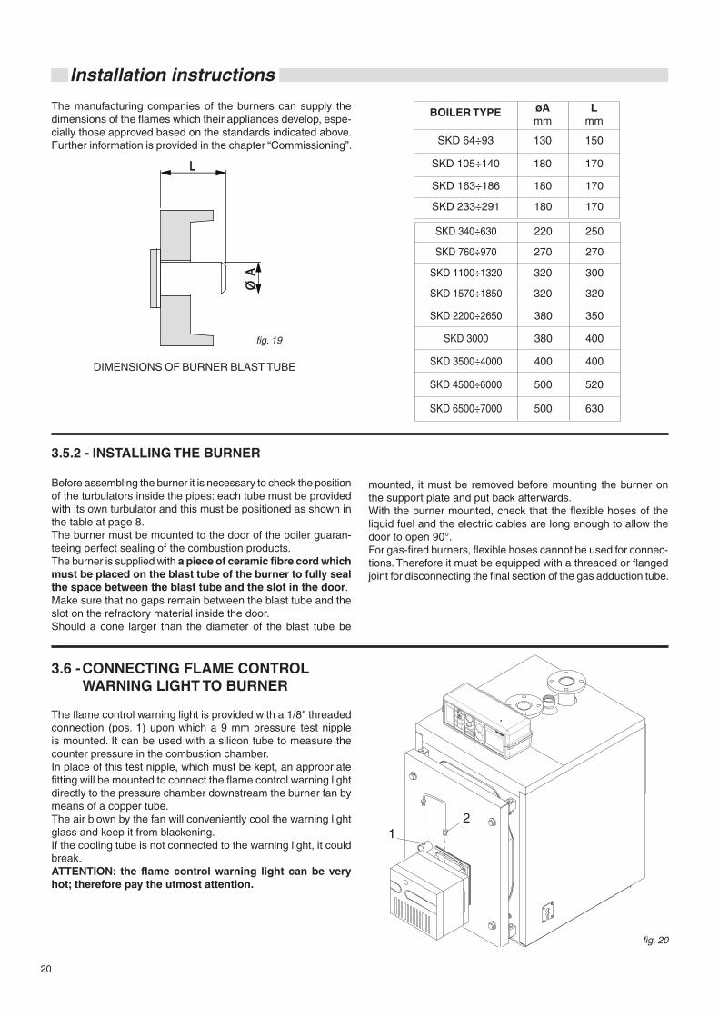
The manufacturing companies of the burners can supply the dimensions of the flames which their appliances develop, espe-cially those approved based on the standards indicated above.Further information is provided in the chapter “Commissioning”.
fig. 19
SKD 2200÷2650 380 350
SKD 1570÷1850 320 320
SKD 1100÷1320 320 300
SKD 760÷970 270 270
SKD 340÷630 220 250
DIMENSIONS OF BURNER BLAST TUBE
SKD 3000 380 400
SKD 3500÷4000 400 400
3.6 - CONNECTING FLAME CONTROL WARNING LIGHT TO BURNER
The flame control warning light is provided with a 1/8" threaded connection (pos. 1) upon which a 9 mm pressure test nipple is mounted. It can be used with a silicon tube to measure the counter pressure in the combustion chamber. In place of this test nipple, which must be kept, an appropriate fitting will be mounted to connect the flame control warning light directly to the pressure chamber downstream the burner fan by means of a copper tube.The air blown by the fan will conveniently cool the warning light glass and keep it from blackening.If the cooling tube is not connected to the warning light, it could break.ATTENTION: the flame control warning light can be very hot; therefore pay the utmost attention.
fig. 20
3.5.2 - INSTALLING THE BURNER
Before assembling the burner it is necessary to check the position of the turbulators inside the pipes: each tube must be provided with its own turbulator and this must be positioned as shown in the table at page 8.The burner must be mounted to the door of the boiler guaran-teeing perfect sealing of the combustion products.The burner is supplied with a piece of ceramic fibre cord which must be placed on the blast tube of the burner to fully seal the space between the blast tube and the slot in the door.Make sure that no gaps remain between the blast tube and the slot on the refractory material inside the door.Should a cone larger than the diameter of the blast tube be
mounted, it must be removed before mounting the burner on the support plate and put back afterwards.With the burner mounted, check that the flexible hoses of the liquid fuel and the electric cables are long enough to allow the door to open 90°.For gas-fired burners, flexible hoses cannot be used for connec-tions. Therefore it must be equipped with a threaded or flanged joint for disconnecting the final section of the gas adduction tube.
L
Ø A
SKD 4500÷6000 500 520
SKD 6500÷7000 500 630
BOILER TYPE øA mm
L mm
SKD 233÷291 180 170
SKD 163÷186 180 170
SKD 105÷140 180 170
SKD 64÷93 130 150
21
Technical features and dimensions3.7 - FURNACE DOOR: ADJUSTMENT, OPENING AND CLOSINGIMPORTANT- The door of the boiler must be opened when it is cooled off
to avoid damaging the fibre due to thermal shock.- The insulation fibre of the door can show cracks after a short
time of operation; this however does not reduce its insulation capacity nor jeopardise its lifespan.
- The door fibre is easy to replace and is covered by a two-year warranty.
- In the event of using naphtha with viscosity 3÷5°E or higher, or B.T.Z., the fibre door will need to be replaced (on demand) by a door with a suitable refractory cast.
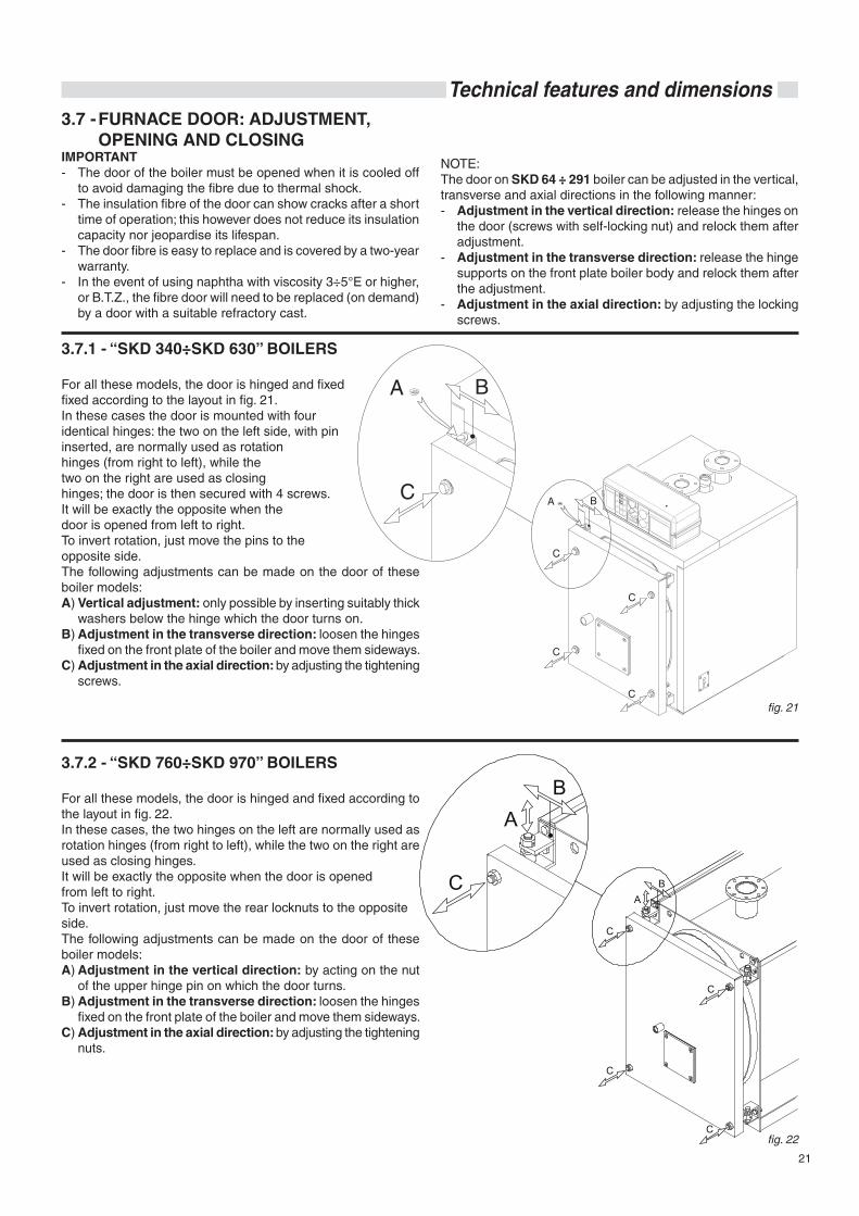
3.7.1 - “SKD 340÷SKD 630” BOILERS
For all these models, the door is hinged and fixed fixed according to the layout in fig. 21.In these cases the door is mounted with four identical hinges: the two on the left side, with pin inserted, are normally used as rotation hinges (from right to left), while the two on the right are used as closing hinges; the door is then secured with 4 screws.It will be exactly the opposite when the door is opened from left to right. To invert rotation, just move the pins to the opposite side.The following adjustments can be made on the door of these boiler models:A) Vertical adjustment: only possible by inserting suitably thick
washers below the hinge which the door turns on. B) Adjustment in the transverse direction: loosen the hinges
fixed on the front plate of the boiler and move them sideways.C) Adjustment in the axial direction: by adjusting the tightening
screws.
fig. 21
3.7.2 - “SKD 760÷SKD 970” BOILERS
For all these models, the door is hinged and fixed according to the layout in fig. 22.In these cases, the two hinges on the left are normally used as rotation hinges (from right to left), while the two on the right are used as closing hinges.It will be exactly the opposite when the door is opened from left to right.To invert rotation, just move the rear locknuts to the opposite side.The following adjustments can be made on the door of these boiler models:A) Adjustment in the vertical direction: by acting on the nut
of the upper hinge pin on which the door turns. B) Adjustment in the transverse direction: loosen the hinges
fixed on the front plate of the boiler and move them sideways.C) Adjustment in the axial direction: by adjusting the tightening
nuts.
C
C
C
C
BA
C
BA
fig. 22
NOTE:The door on SKD 64 ÷ 291 boiler can be adjusted in the vertical, transverse and axial directions in the following manner:- Adjustment in the vertical direction: release the hinges on
the door (screws with self-locking nut) and relock them after adjustment.
- Adjustment in the transverse direction: release the hinge supports on the front plate boiler body and relock them after the adjustment.
- Adjustment in the axial direction: by adjusting the locking screws.

22
Installation instructions
3.7.3 - “SKD 1100÷SKD 7000” BOILERS
For all these models, the door is hinged and fixed according to the layout in fig. 23.In these cases, the two hinges on the left are normally used as rotation hinges (from right to left), while the two on the right are used as closing hinges.It will be exactly the opposite when the door is opened from left to right.To invert rotation, just move the door support bushings.The following adjustments can be made on the door of these boiler models:A) Adjustment in the vertical direction: by acting on the nut
of the upper hinge pin on which the door turns. B) Adjustment in the transverse direction: loosen the hinges
fixed on the front plate of the boiler and move them sideways.C) Adjustment in the axial direction: by adjusting the tightening
nuts.
C
C
C
C
C
B
B
A
A
fig. 23
3.7.4 - IMPORTANT NOTE
Before opening the door of the furnace, take the following safety measures:- Close the fuel supply (diesel oil or gas) to the burner.- Cool the boiler off by having water circulate and then discon-
nect electrical power.
- Place a sign on the boiler with the following text: DO NOT USE, BOILER MAINTENANCE UNDERWAY, OUT OF SERVICE.
3.8 - CONNECTING FLUE EXHAUST PIPE
To connect the flue gas exhaust pipe, local and national stand-ards must be respected (see Standards UNI-CIG 7129 point 4 and 7131 point 5).
The SKD boiler can be attached to the chimney in different ways; straight pipes or elbows can be used to exit from the rear, on the left, on the right, or else vertically to enter the flue at a higher level.It is recommended to insulate the pipe connecting to the chimney to reduce heat loss and noise.Along the section connecting the boiler to the flue there must be suitable points for measuring flue gas temperature and analysing combustion products.
Use only exhaust pipes suitable for the type of fuel used. The supplier will have no contractual or ex-tra-contractual liability for damage caused due to incorrect installation and use and anyway failure to comply with the instructions provided by the manufacturer.
When performing replacement installations, ALWAYS re-place the flue gas exhaust accessory as well.
The flue must comply with the standards in force.
23
Technical features and dimensions
3.9 - CONNECTING BOILER TO SYSTEM
Attention!Before connecting the boiler to the heating system, thoroughly clean the piping with an appropriate product in order to eliminate metallic residue from processing and weld-ing, oil and grease which could be present and which, reaching the boiler, could alter its functioning.Do not use solvents to wash the system as they could damage the system and/or its components.Failure to comply with the instructions of the following manual can cause damage to persons, animals and objects for which the manufacturer cannot be held responsible.
Attention! Make sure that there are no mechanical ten-sion points while connecting the pipes to avoid the risk of leakage!
Heating flow and return pipes must be connected to the boiler at the respective fittings as indicated
on pages 9, 10, 11, 12 and 13.
For the dimensioning of the heating circuit pipes, you must take into account pressure drops caused by radiators, thermostatic valves, radiator stopping valves and by the configuration of the system.
The laying of the pipes must be designed taking every neces-sary precaution to avoid air pockets and to facilitate continuous degassing of the system.
Make sure that the pipes of the water and heating system are not used as earthing electrodes of the electric or telephone system. They are absolutely not suitable for this type of use. Serious damage could result for the piping, boiler and radiators in a short amount of time.
Heating system safety valve discharge
Provide a drain pipe with a funnel and a siphon leading to an appropriate drainage at the heating safety valve. This drainage must be controlled on sight.
Attention!If this precaution is not taken, triggering of the safety valve can cause damage to persons, animals and objects for which the manufac-turer cannot be held responsible.
Connection of expansion vessel
SKD boilers are suitable for operating with forced water circulation both with opened or closed expansion vessel.An expansion vessel is always necessary to compensate the increase in water volume due to heating.
The connection pipes of the expansion vessel will start from the T3 attachment (see DIMENSIONS TABLES) and must have no shut-off valve.
Connecting the filling / draining tap
A specific tap can be connected to the T4 attachment at the rear of the boiler for filling and draining.
3.9.1 - RECIRCULATION PUMP
SKD boilers must always operate with forced water circulation and a minimum return temperature of 55°C.It is therefore recommended to use a recirculation pump, which also has an anti-condensation function, installed between the flow and return connections upstream the mixing valve.This pump is dimensioned according to the formula:
Q = P x 22
where Q = Flow rate in l/hr P = Nominal output of boiler in kWand hydraulic head 1÷2 m HO
3.10 - FILLING THE SYSTEM
Attention!Do not mix the heating water with incorrect concentrations of antifreeze or anti-corrosion substances! This could damage the gaskets and cause noise during operation. The Manufacturer shall not be held liable for damage to persons, animals or property due to failure to comply with the instructions above.
When all system connections have been completed, the circuit can be filled. This operation must be performed carefully, respecting the following phases:- open the radiator air release valves.- open the filling tap gradually, making sure that the automatic
air release valves installed on the system work properly.- close the radiator air release valves as soon as water comes
out.
24
Installation instructions
- check the pressure gauge until pressure reaches approxi-mately 1 bar.
- close the filling tap and bleed air once again through the radiator air release valves.
- make sure that all the connections are watertight.- after commissioning the boiler and bringing the system to
the operating temperature, stop the pumps and repeat the air bleed operations.
- let the system cool off and, if necessary, return the water pressure to 1 bar.
NOTEThe water pressure in the heating system must not drop below 1 bar; open the filling tap on the boiler when the pressure is too low. This operation must be performed with a cooled system.
NOTEIf the boiler was without electric power, after a certain idle period, the pump could be blocked. Before turning on the main switch, the pump must be unblocked by operating as follows:Introduce a screwdriver in the hole below the pro-tective screw in the centre of the pump intended for this purpose and turn the pump shaft clockwise. After having unblocked the pump, tighten the protective screw and make sure there is no water leakage.
ATTENTION! After removing the protective screw, a small amount of water could leak out. Dry off all wet surfaces before powering the boiler.
3.11 - GAS CONNECTION
Danger! The gas connection must be carried out only by a qualified installer who must respect and apply that foreseen by relevant laws in force in the local prescriptions of the supply com-pany. Incorrect installation can cause damage to persons, animals and objects for which the manufacturer cannot be held responsible.
Before installation, we recommend a thor-ough inner cleaning of all fuel adduction piping to remove any residue which could jeopardise proper operation of the boiler.
Attention! Make sure that there are no mechanical tension points while connecting gas to avoid the risk of leakage!
If you smell gas: a) Do not turn electric switches on or off, use
a telephone or any other object which can create sparks;
b) Immediately open doors and windows to create an air current to air out the room;
c) Shut the gas cocks; d) Request the intervention of professionally
qualified personnel.
As a precaution against gas leaks, we recom-mend installing a monitoring and protection system consisting of a gas leak detector coupled with a shut-off solenoid valve on the gas feed line.
The supply pipes must have a cross-section sufficient for the flow rate of the burner.
You should nonetheless comply with the “General installation regulations” laid down in the standards UNI 7129, UNI 7131 and UNI 11137-1.
Before commissioning an internal gas distribution system and therefore before connecting it to the gas meter, check its sealing carefully.
If any part of the system is out of sight, the sealing test must be done before the pipes are covered.
Before connecting the appliances, the system must be tested with air or inert gas at a pressure of at least 100 mbar.
The following operations and checks must also be performed while commissioning the system:- Open the meter and air release valve to bleed the air from
the piping of the appliances, performing the same operation for each appliance.
- With the appliances closed, check that there are no gas leaks. The pressure gauge must show no pressure drop during the second quarter of an hour from the start of the test. Gas leaks must be found with a soapy solution or similar product and eliminated. Never look for gas leaks with an open flame.
25
Technical features and dimensions
3.12 - PACKAGING
SKD boilers are supplied complete with the door and smoke chamber assembled, while the casing and insulation are included in separate cardboard package(s).The panel and accessories are inside the combustion chamber.Before starting installation, make sure that the length and width of the boiler body received correspond respectively to the dimen-sions M, Q and R of the boiler you have ordered, provided on the previous tables, and that the boxes containing the casing, or part of it, are marked as in the table at the bottom of the page.
The casing of boilers from SKD 340 to SKD 510, complete with insulation mats, is contained in one box only.
The casing of boilers SKD 630 to SKD 2200 is contained in 3 boxes.
The casing of SKD 2650 boilers is contained in 4 boxes.
The casing of the SKD 3000 and SKD 3500 boilers is con-tained in 3 boxes.
The casing of the SKD 4000 boilers is contained in 4 boxes.
Boilers included between the SKD 4500 and SKD 7000 models, are supplied with casing.
In addition to the panel board packed in its own box, the following accessories are found in the combustion chamber:
- 1 box containing hydraulic connection flanges, with relative gaskets and bolts, cylindrical brush to clean pipes.
- cleaning brush extensions. - turbulator extractor. - ceramic fibre cord to insulate between burner blast tube and
door.
Upon reception, make sure that the supply is com-plete and undamaged.
Keep the packaging material (cardboard boxes, straps, plastic bags, etc.) out of the reach of children as they are potential sources of danger.The Manufacturer shall not be held liable for damage to persons, animals or property due to failure to comply with the instructions above.
The document envelope, besides the appliance, contains:
- Hydraulic test certificate - Heating system booklet - System manager operating instructions - Installation and maintenance instruction booklet- Warranty- Local ventilation requirements label.
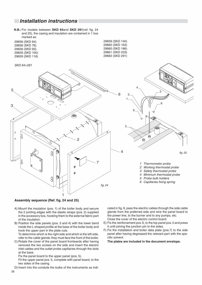
26
Installation instructions
N.B.: For models between SKD 64and SKD 291(ref. fig. 24 and 25), the casing and insulation are contained in 1 box marked as:
SKD 64÷291
fig. 24
cated in fig. 9, pass the electric cables through the side cable glands from the preferred side and wire the panel board to the power line, to the burner and to any pumps, etc.
Close the cover of the electric control board.E) Fix the reinforcement pos. 6, to the top panel pos. 5 and press
it until joining the junction pin to the sides.F) Fix the installation and boiler data plate (pos.7) to the side
panel after having degreased the relevant part with the spe-cific solvent.
The plates are included in the document envelope.
Assembly sequence (Ref. fig. 24 and 25)
A) Mount the insulation (pos. 1) of the boiler body and secure the 2 jointing edges with the elastic straps (pos. 2) supplied in the accessory box, hooking them to the external fabric part of the insulation.
B) Position the side panels (pos. 3 and 4) with the lower bend inside the L-shaped profile at the base of the boiler body and hook the upper part in the plate cuts.
To determine which is the right side and which is the left side, refer to the cable glands: they must face the front of the boiler.
C) Rotate the cover of the panel board frontwards after having removed the two screws on the side and insert the electric inlet cables and the outlet probe capillaries through the slots at the base.
Fix the panel board to the upper panel (pos. 5). Fit the upper panel pos. 5, complete with panel board, to the
two sides of the casing.D) Insert into the conduits the bulbs of the instruments as indi-
29658 (SKD 64) 29658 (SKD 76) 29658 (SKD 93)29659 (SKD 105) 29659 (SKD 116)
29659 (SKD 140)29660 (SKD 163) 29660 (SKD 186)29661 (SKD 233)29662 (SKD 291)
fig. 25
1 Thermometer probe2 Working thermostat probe3 Safety thermostat probe4 Minimum thermostat probe5 Probe bulb holders6 Capillaries fixing spring
27
Technical features and dimensions
N.B.: For models between SKD 340and SKD 510(ref. fig. 26), the casing and insulation are contained in 1 box marked as:
50056 (SKD 340)50057 (SKD 420)50058 (SKD 510)
N.B.: For model SKD 630 (ref. fig. 26) and for models between SKD 760 and SKD 2200 (ref. fig. 28 e 29), the casing and insulation are contained in 3 boxes marked as:
50059 (front casing SKD 630)50060 (rear casing SKD 630)50061 (top casing SKD 630)50062 (front casing SKD 760)50063 (rear casing SKD 760)50064 (top casing SKD 760)50062 (front casing SKD 870)50065 (rear casing SKD 870)50066 (top casing SKD 870)50062 (front casing SKD 970)50068 (top casing SKD 970)50069 (front casing SKD 1100)50070 (rear casing SKD 1100)50071 (top casing SKD 1100)50069 (front casing SKD 1320)50072 (rear casing SKD 1320)50073 (top casing SKD 1320)50074 (front casing SKD 1570)50075 (rear casing SKD 1570)50076 (top casing SKD 1570)50074 (front casing SKD 1850)50077 (rear casing SKD 1850)50078 (top casing SKD 1850)50079 (front casing SKD 2200)50080 (rear casing SKD 2200)50081 (top casing SKD 2200)
N.B.: For the SKD 2650 model (ref. fig. 30) the casing and insu-lation are contained in 4 boxes.
For models SKD 3000and SKD 3500 (ref. fig. 31), the casing and insulation are contained in 3 boxes:
For the SKD 4000 model (ref. fig. 32) the casing and insu-lation are contained in 4 boxes marked:
50079 (front casing SKD 2650)50082 (rear casing SKD 2650)50083 (top casing SKD 2650)50084 (middle casing SKD 2650)30111 (front casing SKD 3000)30112 (rear casing SKD 3000)30113 (middle casing SKD 3000)30114 (front casing SKD 3500)30115 (rear casing SKD 3500)30116 (middle casing SKD 3500)30114 (front casing SKD 4000)30115 (rear casing SKD 4000)30116 (middle casing SKD 4000)30543 (rear casing SKD 4000)
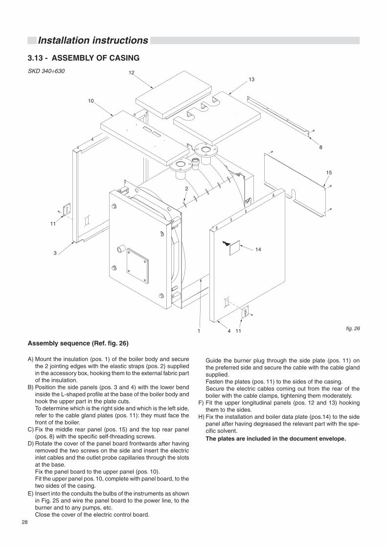
28
Installation instructions
3.13 - ASSEMBLY OF CASING
SKD 340÷630
fig. 26
Guide the burner plug through the side plate (pos. 11) on the preferred side and secure the cable with the cable gland supplied.
Fasten the plates (pos. 11) to the sides of the casing. Secure the electric cables coming out from the rear of the
boiler with the cable clamps, tightening them moderately.F) Fit the upper longitudinal panels (pos. 12 and 13) hooking
them to the sides.H) Fix the installation and boiler data plate (pos.14) to the side
panel after having degreased the relevant part with the spe-cific solvent.
The plates are included in the document envelope.
Assembly sequence (Ref. fig. 26)
A) Mount the insulation (pos. 1) of the boiler body and secure the 2 jointing edges with the elastic straps (pos. 2) supplied in the accessory box, hooking them to the external fabric part of the insulation.
B) Position the side panels (pos. 3 and 4) with the lower bend inside the L-shaped profile at the base of the boiler body and hook the upper part in the plate cuts.
To determine which is the right side and which is the left side, refer to the cable gland plates (pos. 11): they must face the front of the boiler.
C) Fix the middle rear panel (pos. 15) and the top rear panel (pos. 8) with the specific self-threading screws.
D) Rotate the cover of the panel board frontwards after having removed the two screws on the side and insert the electric inlet cables and the outlet probe capillaries through the slots at the base.
Fix the panel board to the upper panel (pos. 10). Fit the upper panel pos. 10, complete with panel board, to the
two sides of the casing.E) Insert into the conduits the bulbs of the instruments as shown
in Fig. 25 and wire the panel board to the power line, to the burner and to any pumps, etc.
Close the cover of the electric control board.
11
4 111
8
2
10
1213
314
15
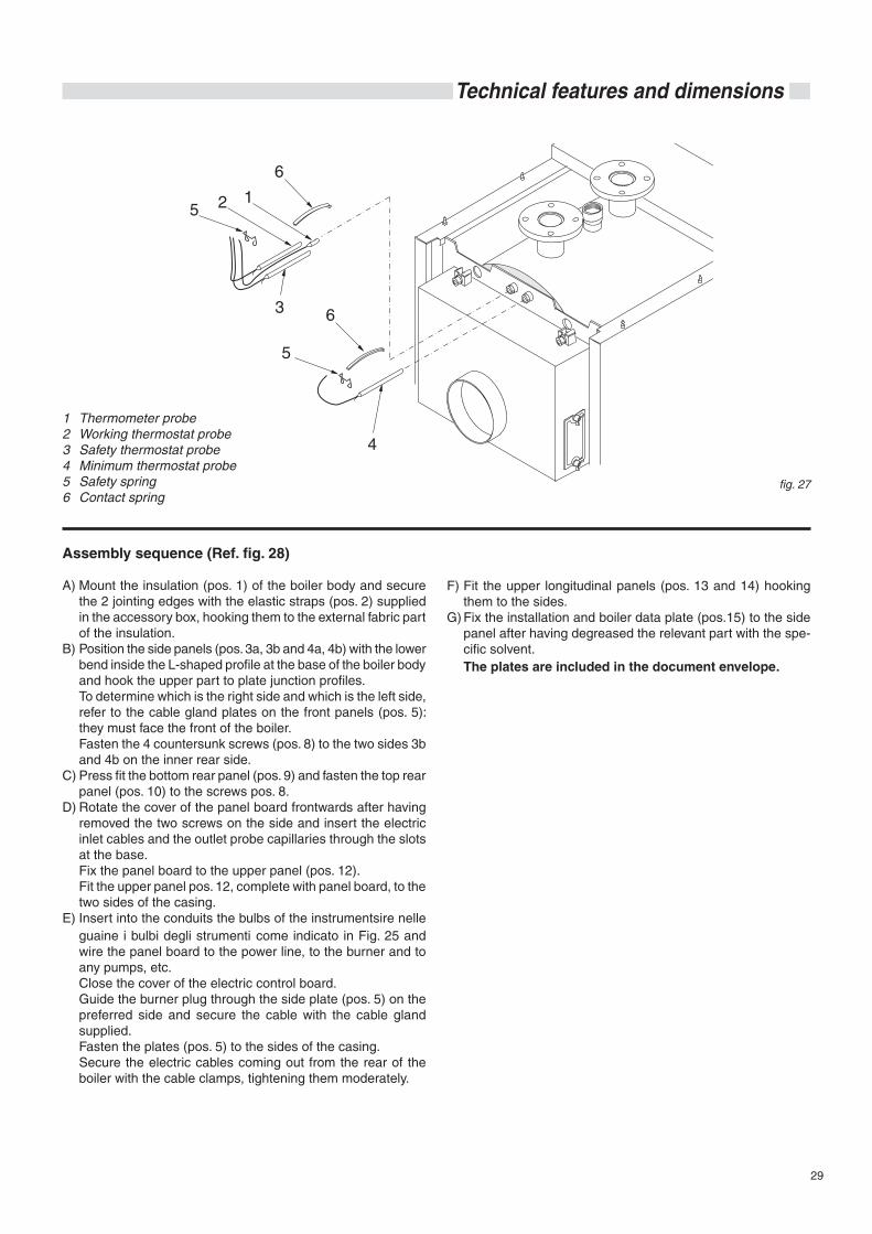
29
Technical features and dimensions
fig. 27
1 Thermometer probe2 Working thermostat probe3 Safety thermostat probe4 Minimum thermostat probe5 Safety spring6 Contact spring
Assembly sequence (Ref. fig. 28)
A) Mount the insulation (pos. 1) of the boiler body and secure the 2 jointing edges with the elastic straps (pos. 2) supplied in the accessory box, hooking them to the external fabric part of the insulation.
B) Position the side panels (pos. 3a, 3b and 4a, 4b) with the lower bend inside the L-shaped profile at the base of the boiler body and hook the upper part to plate junction profiles.
To determine which is the right side and which is the left side, refer to the cable gland plates on the front panels (pos. 5): they must face the front of the boiler.
Fasten the 4 countersunk screws (pos. 8) to the two sides 3b and 4b on the inner rear side.
C) Press fit the bottom rear panel (pos. 9) and fasten the top rear panel (pos. 10) to the screws pos. 8.
D) Rotate the cover of the panel board frontwards after having removed the two screws on the side and insert the electric inlet cables and the outlet probe capillaries through the slots at the base.
Fix the panel board to the upper panel (pos. 12). Fit the upper panel pos. 12, complete with panel board, to the
two sides of the casing.E) Insert into the conduits the bulbs of the instrumentsire nelle
guaine i bulbi degli strumenti come indicato in Fig. 25 and wire the panel board to the power line, to the burner and to any pumps, etc.
Close the cover of the electric control board. Guide the burner plug through the side plate (pos. 5) on the
preferred side and secure the cable with the cable gland supplied.
Fasten the plates (pos. 5) to the sides of the casing. Secure the electric cables coming out from the rear of the
boiler with the cable clamps, tightening them moderately.
F) Fit the upper longitudinal panels (pos. 13 and 14) hooking them to the sides.
G) Fix the installation and boiler data plate (pos.15) to the side panel after having degreased the relevant part with the spe-cific solvent.
The plates are included in the document envelope.
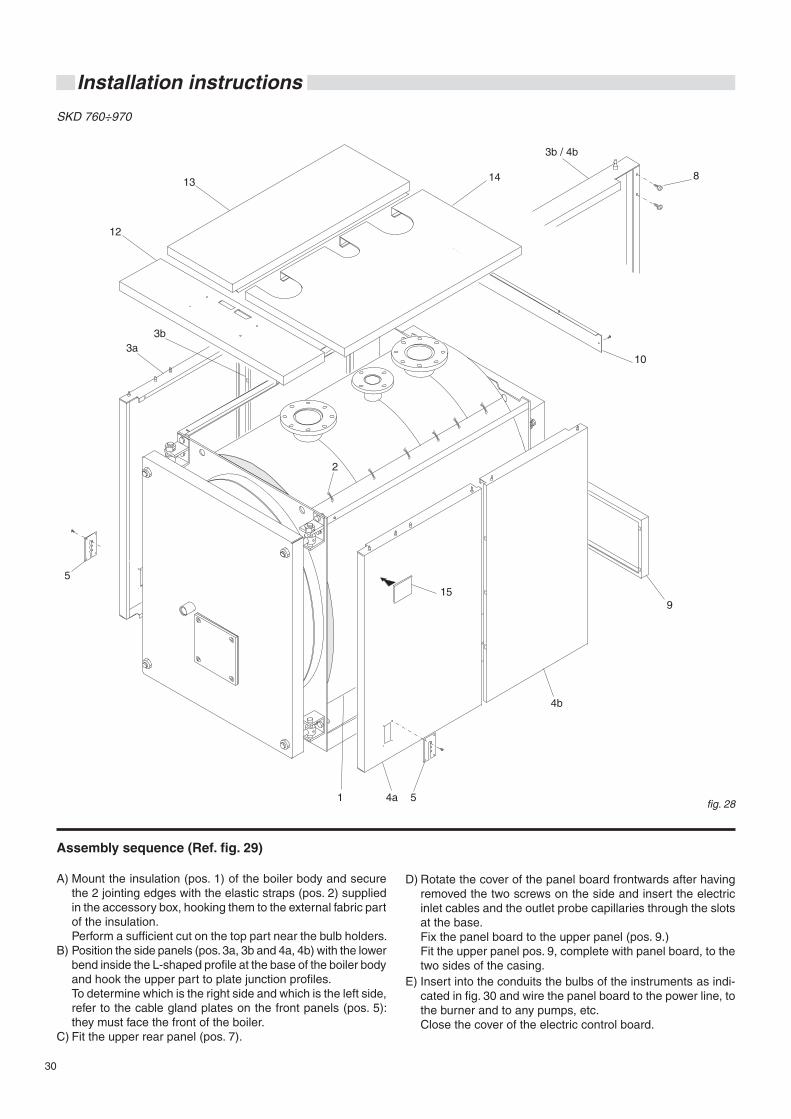
30
Installation instructions
SKD 760÷970
fig. 28
Assembly sequence (Ref. fig. 29)
A) Mount the insulation (pos. 1) of the boiler body and secure the 2 jointing edges with the elastic straps (pos. 2) supplied in the accessory box, hooking them to the external fabric part of the insulation.
Perform a sufficient cut on the top part near the bulb holders.B) Position the side panels (pos. 3a, 3b and 4a, 4b) with the lower
bend inside the L-shaped profile at the base of the boiler body and hook the upper part to plate junction profiles.
To determine which is the right side and which is the left side, refer to the cable gland plates on the front panels (pos. 5): they must face the front of the boiler.
C) Fit the upper rear panel (pos. 7).
D) Rotate the cover of the panel board frontwards after having removed the two screws on the side and insert the electric inlet cables and the outlet probe capillaries through the slots at the base.
Fix the panel board to the upper panel (pos. 9.) Fit the upper panel pos. 9, complete with panel board, to the
two sides of the casing.E) Insert into the conduits the bulbs of the instruments as indi-
cated in fig. 30 and wire the panel board to the power line, to the burner and to any pumps, etc.
Close the cover of the electric control board.
2
8
5
3a
3b / 4b
3b
12
13 14
4a
4b
51
9
10
15
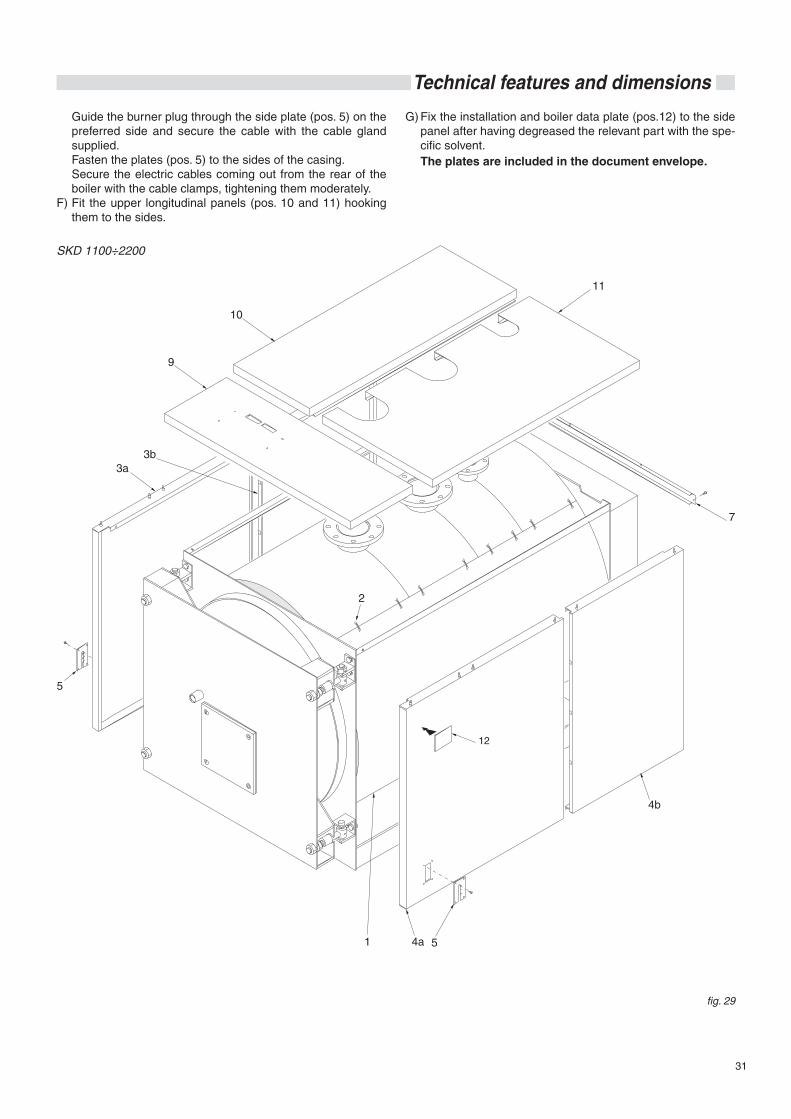
31
Technical features and dimensions
Guide the burner plug through the side plate (pos. 5) on the preferred side and secure the cable with the cable gland supplied.
Fasten the plates (pos. 5) to the sides of the casing. Secure the electric cables coming out from the rear of the
boiler with the cable clamps, tightening them moderately.F) Fit the upper longitudinal panels (pos. 10 and 11) hooking
them to the sides.
G) Fix the installation and boiler data plate (pos.12) to the side panel after having degreased the relevant part with the spe-cific solvent.
The plates are included in the document envelope.
SKD 1100÷2200
fig. 29
2
5
3a3b
9
10
11
7
4a 51
4b
12
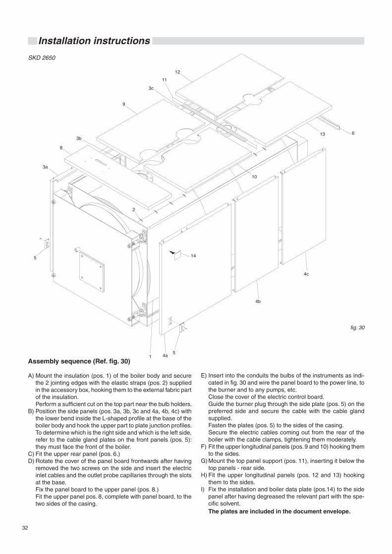
32
Installation instructions
SKD 2650
Assembly sequence (Ref. fig. 30)
A) Mount the insulation (pos. 1) of the boiler body and secure the 2 jointing edges with the elastic straps (pos. 2) supplied in the accessory box, hooking them to the external fabric part of the insulation.
Perform a sufficient cut on the top part near the bulb holders.B) Position the side panels (pos. 3a, 3b, 3c and 4a, 4b, 4c) with
the lower bend inside the L-shaped profile at the base of the boiler body and hook the upper part to plate junction profiles.
To determine which is the right side and which is the left side, refer to the cable gland plates on the front panels (pos. 5): they must face the front of the boiler.
C) Fit the upper rear panel (pos. 6.)D) Rotate the cover of the panel board frontwards after having
removed the two screws on the side and insert the electric inlet cables and the outlet probe capillaries through the slots at the base.
Fix the panel board to the upper panel (pos. 8.) Fit the upper panel pos. 8, complete with panel board, to the
two sides of the casing.
E) Insert into the conduits the bulbs of the instruments as indi-cated in fig. 30 and wire the panel board to the power line, to the burner and to any pumps, etc.
Close the cover of the electric control board. Guide the burner plug through the side plate (pos. 5) on the
preferred side and secure the cable with the cable gland supplied.
Fasten the plates (pos. 5) to the sides of the casing. Secure the electric cables coming out from the rear of the
boiler with the cable clamps, tightening them moderately.F) Fit the upper longitudinal panels (pos. 9 and 10) hooking them
to the sides.G) Mount the top panel support (pos. 11), inserting it below the
top panels - rear side. H) Fit the upper longitudinal panels (pos. 12 and 13) hooking
them to the sides.I) Fix the installation and boiler data plate (pos.14) to the side
panel after having degreased the relevant part with the spe-cific solvent.
The plates are included in the document envelope.
fig. 30
145
3a
3b
3c
9
8
12
11
2
1 4a
4b
4c
5
613
10
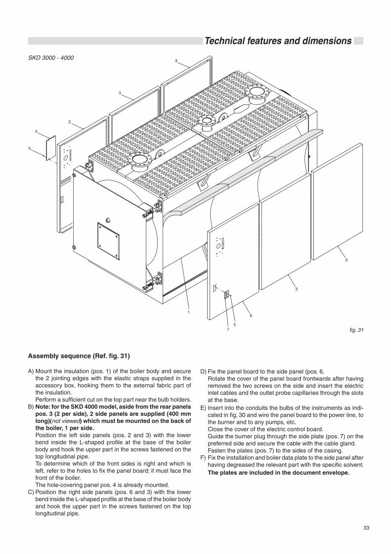
33
Technical features and dimensions
Assembly sequence (Ref. fig. 31)
A) Mount the insulation (pos. 1) of the boiler body and secure the 2 jointing edges with the elastic straps supplied in the accessory box, hooking them to the external fabric part of the insulation.
Perform a sufficient cut on the top part near the bulb holders.B) Note: for the SKD 4000 model, aside from the rear panels
pos. 3 (2 per side), 2 side panels are supplied (400 mm long)(not viewed) which must be mounted on the back of the boiler, 1 per side.
Position the left side panels (pos. 2 and 3) with the lower bend inside the L-shaped profile at the base of the boiler body and hook the upper part in the screws fastened on the top longitudinal pipe.
To determine which of the front sides is right and which is left, refer to the holes to fix the panel board; it must face the front of the boiler.
The hole-covering panel pos. 4 is already mounted.C) Position the right side panels (pos. 6 and 3) with the lower
bend inside the L-shaped profile at the base of the boiler body and hook the upper part in the screws fastened on the top longitudinal pipe.
D) Fix the panel board to the side panel (pos. 6. Rotate the cover of the panel board frontwards after having
removed the two screws on the side and insert the electric inlet cables and the outlet probe capillaries through the slots at the base.
E) Insert into the conduits the bulbs of the instruments as indi-cated in fig. 30 and wire the panel board to the power line, to the burner and to any pumps, etc.
Close the cover of the electric control board. Guide the burner plug through the side plate (pos. 7) on the
preferred side and secure the cable with the cable gland. Fasten the plates (pos. 7) to the sides of the casing.F) Fix the installation and boiler data plate to the side panel after
having degreased the relevant part with the specific solvent. The plates are included in the document envelope.
SKD 3000 - 4000
fig. 31
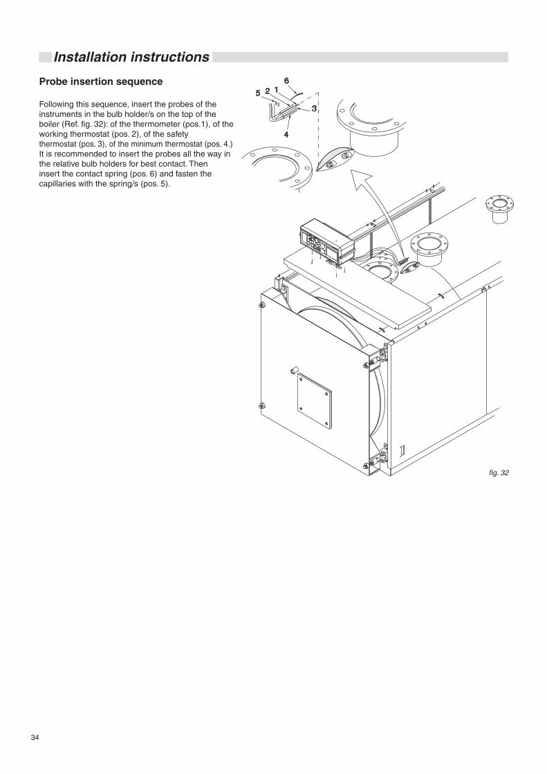
34
Installation instructions
Probe insertion sequence
Following this sequence, insert the probes of the instruments in the bulb holder/s on the top of the boiler (Ref. fig. 32): of the thermometer (pos.1), of the working thermostat (pos. 2), of the safety thermostat (pos. 3), of the minimum thermostat (pos. 4.)It is recommended to insert the probes all the way in the relative bulb holders for best contact. Then insert the contact spring (pos. 6) and fasten the capillaries with the spring/s (pos. 5).
fig. 32
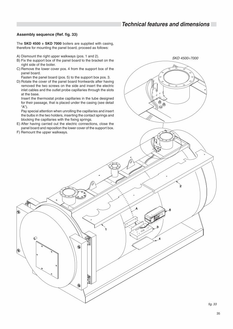
35
Technical features and dimensions
Assembly sequence (Ref. fig. 33)
The SKD 4500 ÷ SKD 7000 boilers are supplied with casing, therefore for mounting the panel board, proceed as follows:
A) Dismount the right upper walkways (pos. 1 and 2).B) Fix the support box of the panel board to the bracket on the
right side of the boiler.C) Remove the lower cover pos. 4 from the support box of the
panel board. Fasten the panel board (pos. 5) to the support box pos. 3.D) Rotate the cover of the panel board frontwards after having
removed the two screws on the side and insert the electric inlet cables and the outlet probe capillaries through the slots at the base.
Insert the thermostat probe capillaries in the tube designed for their passage, that is placed under the casing (see detail “A”).
Pay special attention when unrolling the capillaries and insert the bulbs in the two holders, inserting the contact springs and blocking the capillaries with the fixing springs.
E) After having carried out the electric connections, close the panel board and reposition the lower cover of the support box.
F) Remount the upper walkways.
fig. 33
SKD 4500÷7000

36
Installation instructions
3.14 - ELECTRICAL CONNECTIONS
General warnings
The electrical safety of the appliance is guaranteed only when it has been properly connected to an efficient earthing system carried out as intended by safety standards in force: pipes of the gas, water and heating systems are absolutely unsuitable as earthing electrodes.
It is necessary to verify this fundamental safety requirement. If in doubt, have the electric system carefully checked by profes-sionally qualified personnel as the manufacturer is not liable for damage caused by failure to provide an earthing system.
Have professionally qualified personnel check that the electric system is adequate for the maximum power absorbed by the appliance, indicated on the data plate. Make sure in particular that the cross-section of the cables is suitable for the power absorbed by the appliance.
Adapters, multiple sockets and/or extension cords cannot be used to power the appliance.
Use of any type of component using electric energy requires the observance of some fundamental rules, such as: • do not touch the appliance with wet and/or moist parts of the
body and/or in bare feet; • do not pull the electric cables; • do not leave the appliance exposed to atmospheric agents
(rain, sun, etc.) unless expressly designed; • do not allow children or unskilled persons to use the appli-
ance.
230V electric power supply connection
The electrical connections are illustrated in chap. 3.15, 3.16.
The boiler installation requires a connection to a 230 V - 50 Hz electric mains: this connection must be properly carried out as provided for by current IEC regulations.
Danger!Only a qualified technician may perform the electrical in-stallation.Before performing connections or any type of operation on electrical parts, always disconnect electrical power and make sure that it cannot be reconnected accidentally.
Remember that a bipolar switch must be installed on the boiler power line with over 3 mm between contacts, easy to access, making maintenance quick and safe.
The power cable must be replaced by authorised technical personnel. Failure to comply with the above can jeopardise the safety of the appliance.
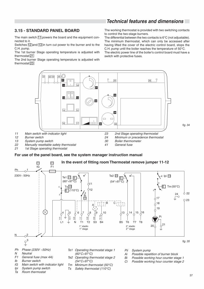
37
Technical features and dimensions
fig. 34
3.15 - STANDARD PANEL BOARD
11 Main switch with indicator light12 Burner switch13 System pump switch22 Manually resettable safety thermostat21 1st Stage operating thermostat
23 2nd Stage operating thermostat 24 Minimum or precedence thermostat30 Boiler thermometer41 General fuse
Te1 Operating thermostat stage 1 (60°C÷97°C)Te2 Operating thermostat stage 2 (54°C÷97°C)Tm Minimum thermostat (50°C)Ts Safety thermostat (110°C)
Ph Phase (230V ~50Hz)N NeutralF1 General fuse (max 4A)Ib Burner switchIG Main switch with indicator lightIpi System pump switchTa Room thermostat
fig. 35
Pii System pumpAi Possible repetition of burner blockBi Possible working hour counter stage 1 Ci Possible working hour counter stage 2
In the event of fitting room Thermostat remove jumper 11-12
The main switch 11 powers the board and the equipment con-nected to it. Switches 12 and 13 in turn cut power to the burner and to the C.H. pump.The 1st burner Stage operating temperature is adjusted with thermostat 21The 2nd burner Stage operating temperature is adjusted with thermostat 23
The working thermostat is provided with two switching contacts to control the two-stage burners.The differential between the two contacts is 6°C (not adjustable).The minimum thermostat, which can only be accessed after having lifted the cover of the electric control board, stops the C.H. pump until the boiler reaches the temperature of 50°C.The electric power line of the boiler's control board must have a switch with protective fuses.
For use of the panel board, see the system manager instruction manual
21
22
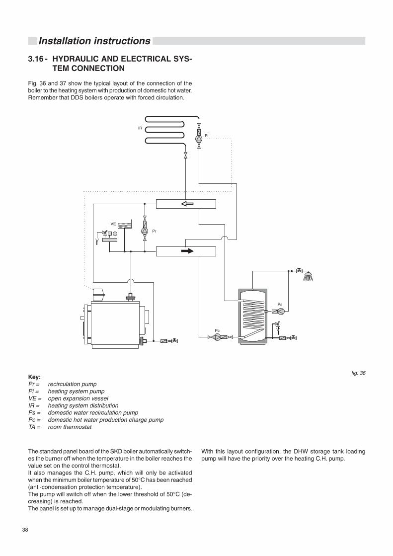
38
Installation instructions
3.16 - HYDRAULIC AND ELECTRICAL SYS-TEM CONNECTION
Fig. 36 and 37 show the typical layout of the connection of the boiler to the heating system with production of domestic hot water.Remember that DDS boilers operate with forced circulation.
Key:Pr = recirculation pump Pi = heating system pumpVE = open expansion vesselIR = heating system distribution Ps = domestic water recirculation pumpPc = domestic hot water production charge pumpTA = room thermostat
The standard panel board of the SKD boiler automatically switch-es the burner off when the temperature in the boiler reaches the value set on the control thermostat.It also manages the C.H. pump, which will only be activated when the minimum boiler temperature of 50°C has been reached (anti-condensation protection temperature).The pump will switch off when the lower threshold of 50°C (de-creasing) is reached.The panel is set up to manage dual-stage or modulating burners.
With this layout configuration, the DHW storage tank loading pump will have the priority over the heating C.H. pump.
fig. 36
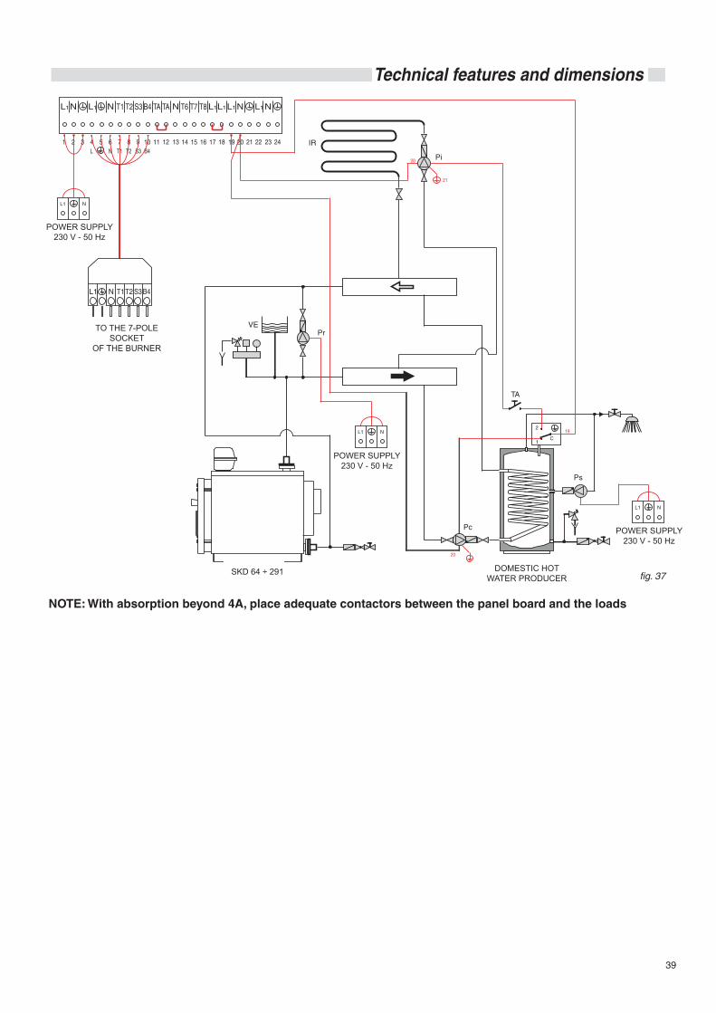
39
Technical features and dimensions
fig. 37
NOTE: With absorption beyond 4A, place adequate contactors between the panel board and the loads
DOMESTIC HOT WATER PRODUCER
POWER SUPPLY230 V - 50 Hz
POWER SUPPLY230 V - 50 Hz
POWER SUPPLY230 V - 50 Hz
TO THE 7-POLE SOCKET
OF THE BURNER
SKD 64 ÷ 291
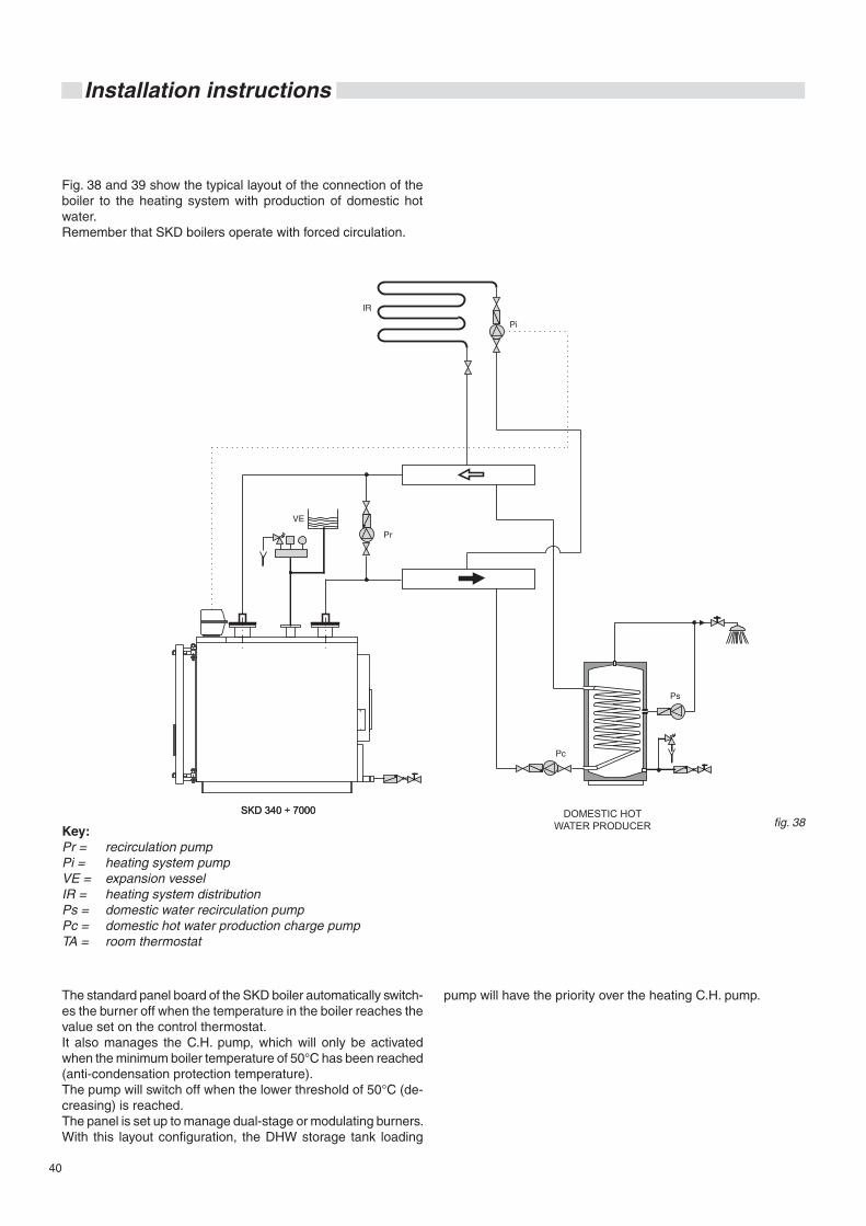
40
Installation instructions
Fig. 38 and 39 show the typical layout of the connection of the boiler to the heating system with production of domestic hot water.Remember that SKD boilers operate with forced circulation.
Key:Pr = recirculation pump Pi = heating system pumpVE = expansion vesselIR = heating system distribution Ps = domestic water recirculation pumpPc = domestic hot water production charge pumpTA = room thermostat
The standard panel board of the SKD boiler automatically switch-es the burner off when the temperature in the boiler reaches the value set on the control thermostat.It also manages the C.H. pump, which will only be activated when the minimum boiler temperature of 50°C has been reached (anti-condensation protection temperature).The pump will switch off when the lower threshold of 50°C (de-creasing) is reached.The panel is set up to manage dual-stage or modulating burners.With this layout configuration, the DHW storage tank loading
pump will have the priority over the heating C.H. pump.
fig. 38SKD 340 ÷ 7000SKD 340 ÷ 7000 DOMESTIC HOT
WATER PRODUCER
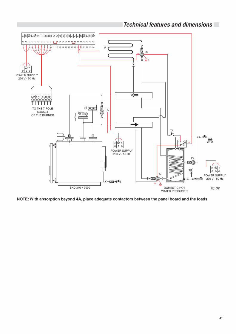
41
Technical features and dimensions
fig. 39
NOTE: With absorption beyond 4A, place adequate contactors between the panel board and the loads
DOMESTIC HOT WATER PRODUCER
POWER SUPPLY230 V - 50 Hz
POWER SUPPLY230 V - 50 Hz
POWER SUPPLY230 V - 50 Hz
TO THE 7-POLE SOCKET
OF THE BURNER
SKD 340 ÷ 7000
42
Installation instructions
3.17 - COMMISSIONING
Preliminary checks
Commissioning must be done by profession-ally qualified personnel. The Manufacturer shall not be held liable for damage to persons, animals or property due to failure to comply with the instructions above.
Before commissioning the boiler, check that:
- installation complies with standards UNI 7129 and 7131 for the gas part and with standards IEC 64-8 and 64-9 for the electrical power;
- the adduction of combustion air and flue gas evacuation are performed correctly according to that laid down by standards in force (UNI 7129/7131);
- the fuel feed system is dimensioned according to the flow rate required for the boiler and is provided with all safety and control systems prescribed by current standards;
- the power supply of the boiler is 230V - 50Hz;
- the system is filled with water (approximately 1 bar pressure on the pressure gauge with the pump stopped);
- any system shut-off gate valves are open;
- the gas to be used (SKD with gas burner) matches the boil-er's calibration one: otherwise perform boiler conversion to using the available gas; this operation must be performed by qualified technical personnel according to regulations in force;
- the gas feed valves (SKD with gas burner) are open;
- there are no gas leaks (SKD with gas burner);
- the external main switch is connected;
- the system safety valves are not blocked and are connected to the sewer system drainage;
- there is no water leakage;
- ventilation conditions and minimum distances are assured to perform maintenance should the boiler be enclosed between furniture or in a niche.
Switching boiler on and off
To switch the boiler on and off, see the “SYSTEM MANAGER OPERATING INSTRUCTIONS” booklet.
Information for system manager
The system manager must be instructed concerning the use and operation of his heating system, in particular:• Give the user the “SYSTEM MANAGER OPERATING IN-
STRUCTIONS”, as well as the other appliance documents inserted in the envelope inside the packaging. The system manager must keep this documentation for future con-sultation.
• Inform the system manager about the importance of the air vents and the flue gas exhaust system, highlighting their essential features and the absolute prohibition of modifying them.
• Inform the system manager concerning control of the sys-tem's water pressure as well as operations to restore it.
• Inform the system manager concerning correct control of temperatures, control units/thermostats and radiators to save energy.
• Remember that the system must receive regular maintenance at least once a year and a combustion analysis must be performed in the timetable foreseen by standards in force.
• Should the appliance be sold or transferred to a new owner or if you move and leave the appliance, always make sure that the instruction manual accompanies it in order to be consulted by the new owner and/or installer.
SKD boilers are forced circulation boilers: it is therefore necessary to make sure that water circulates while the boiler is running.Do not allow the burner to run without the C.H. pump being activated; otherwise the safety thermostat could be triggered.The return temperature shall not drop below:60°C for SKD 64 ÷ 29140°C for SKD 340 ÷ 7000to prevent, or at least limit, flue gas condensation phenomena, which cause early boiler deterioration.The working temperature of the boiler can therefore be adjusted between 50 and 80°C. Room temperature will be reg-ulated by the mixing valve commanded by the heating controller.The system must reach full operating temperature slowly, with possible insertion of secondary rings in the circuit, also to prevent the temperature from dropping below: 60°C for SKD 64 ÷ 291 40°C for SKD 340 ÷ 7000, It is always recommended to install an anti-condensation or recirculation pump (between the flow and the boiler return connection).Returns to low temperatures, below 40°C, cause the flue gas to condense corroding the heat exchange surfaces. You must therefore pay the utmost attention while operating the system.Corrosion caused by acid condensation of combustion products is not covered by the warranty as it is attributable to operation of the system alone.
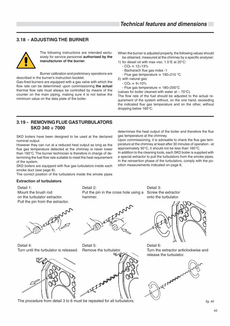
43
Technical features and dimensions
3.18 - ADJUSTING THE BURNER
The following instructions are intended exclu-sively for service personnel authorised by the manufacturer of the burner.
Burner calibration and preliminary operations are described in the burner's instruction booklet.Gas-fired burners are equipped with a gas valve with which the flow rate can be determined: upon commissioning the actual thermal flow rate must always be controlled by means of the counter on the main piping, making sure it is not below the minimum value on the data plate of the boiler.
When the burner is adjusted properly, the following values should be obtained, measured at the chimney by a specific analyser:
1) for diesel oil with max visc. 1.5°E at 20°C: - CO 12÷13% - Bacharach flue gas index ‹1 - Flue gas temperature 190÷210 °C2) with natural gas: - CO 9÷10% - Flue gas temperature 180÷200°C(values for boiler cleaned with water at ~ 70°C).The flow rate of the fuel should be adjusted to the actual re-quirement of the system without, on the one hand, exceeding the indicated flue gas temperature and on the other, without dropping below 160°C.
3.19 - REMOVING FLUE GAS TURBULATORS SKD 340 ÷ 7000
SKD boilers have been designed to be used at the declared nominal output.However they can run at a reduced heat output as long as the flue gas temperature detected at the chimney is never lower than 160°C. The burner technician is therefore in charge of de-termining the fuel flow rate suitable to meet the heat requirement of the system. SKD boilers are equipped with flue gas turbulators inside each smoke duct (see page 8).The correct position of the turbulators inside the smoke pipes
determines the heat output of the boiler and therefore the flue gas temperature at the chimney.Upon commissioning, it is advisable to check the flue gas tem-perature at the chimney at least after 30 minutes of operation - at approximately 50°C, it should not be less than 160°C.In addition to the cleaning tools, each SKD boiler is supplied with a special extractor to pull the turbulators from the smoke pipes.In the reinsertion phase of the turbulators, comply with the po-sition measurements indicated on page 8.
Detail 1: Mount the brush rodon the turbulator extractor.Pull the pin from the extractor.
Detail 2: Put the pin in the cross hole using a hammer.
Detail 3: Screw the extractor onto the turbulator.
Detail 4: Turn until the turbulator is released.
Detail 5: Remove the turbulator.
Detail 6: Turn the extractor anticlockwise and release the turbulator.
The procedure from detail 3 to 6 must be repeated for all turbulators.
Extraction of turbulators
fig. 40
44
Inspections and maintenance
Inspections and maintenance performed professionally and according to a regular schedule as well as the use of original spare parts are of the utmost importance for fault-free operation of the boiler and to guarantee its long life. Yearly maintenance of the appliance is man-datory in compliance with Laws in force.
Failure to perform Inspections and Main-tenance can entail material and personal damage.
We therefore recommend stipulating an inspection or mainte-nance contract.
Inspections help to determine the actual status of the appliance and to compare it with the nominal status. This is done through measuring, controls and observation.
Maintenance is required to eliminate any differences between the actual status and the nominal status. This is normally done by cleaning, setting and replacing individual components subject to wear.
Maintenance intervals and their extent are determined by a specialist based on the status of the appliance ascertained through inspection.
Inspection and maintenance jobs must be performed in the order shown on page 45.
Inspection and maintenance instructions
To assure long-term functionality of your appli-ance and to avoid altering its approved status, only original spare parts must be used.
Before proceeding with maintenance, always perform the following operations:
• Disconnect the electric mains switch. • Isolate the appliance from the electric mains by means of
an isolated device with a contact opening of at least 3 mm (e.g. safety devices or power switches) and make sure that it cannot be re-connected accidentally.
• Close the gas shutoff valve upstream of the boiler (SKD with gas burner).
• Close any shut-off valves on the heating flow and return pipes.
After having completed all maintenance work, always perform the following operations: • Open the heating flow and return pipes. • If necessary, restore the heating system pressure until it
reaches the static pressure relative to the highest point of the system.
• Open the gas shutoff valve (SKD with gas burner). • Reconnect the appliance to the electric mains and engage
the switch.• Check tightness of the appliance on the gas side (SKD with
gas burner) and on the water side. • Vent the heating system and restore pressure if necessary.
Should you decide to temporarily deactivate the boiler, you must:a) intercept the supplies: electric, water and fuel;b) empty the water system if antifreeze is not used.
4 INSPECTIONS ANDMAINTENANCE
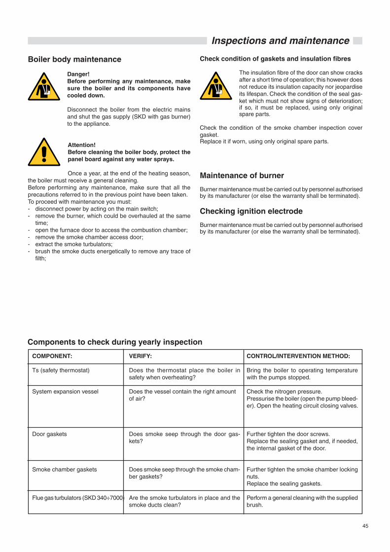
45
Inspections and maintenance
Boiler body maintenance
Danger!Before performing any maintenance, make sure the boiler and its components have cooled down.
Disconnect the boiler from the electric mains and shut the gas supply (SKD with gas burner) to the appliance.
Attention!Before cleaning the boiler body, protect the panel board against any water sprays.
Once a year, at the end of the heating season, the boiler must receive a general cleaning.Before performing any maintenance, make sure that all the precautions referred to in the previous point have been taken.To proceed with maintenance you must:- disconnect power by acting on the main switch;- remove the burner, which could be overhauled at the same
time;- open the furnace door to access the combustion chamber;- remove the smoke chamber access door; - extract the smoke turbulators;- brush the smoke ducts energetically to remove any trace of
filth;
Check condition of gaskets and insulation fibres
The insulation fibre of the door can show cracks after a short time of operation; this however does not reduce its insulation capacity nor jeopardise its lifespan. Check the condition of the seal gas-ket which must not show signs of deterioration; if so, it must be replaced, using only original spare parts.
Check the condition of the smoke chamber inspection cover gasket.Replace it if worn, using only original spare parts.
Maintenance of burner
Burner maintenance must be carried out by personnel authorised by its manufacturer (or else the warranty shall be terminated).
Checking ignition electrode
Burner maintenance must be carried out by personnel authorised by its manufacturer (or else the warranty shall be terminated).
COMPONENT:
Ts (safety thermostat)
System expansion vessel
Door gaskets
Smoke chamber gaskets
Flue gas turbulators (SKD 340÷7000)
VERIFY:
Does the thermostat place the boiler in safety when overheating?
Does the vessel contain the right amountof air?
Does smoke seep through the door gas-kets?
Does smoke seep through the smoke cham-ber gaskets?
Are the smoke turbulators in place and the smoke ducts clean?
CONTROL/INTERVENTION METHOD:
Bring the boiler to operating temperature with the pumps stopped.
Check the nitrogen pressure. Pressurise the boiler (open the pump bleed-er). Open the heating circuit closing valves.
Further tighten the door screws.Replace the sealing gasket and, if needed, the internal gasket of the door.
Further tighten the smoke chamber locking nuts.Replace the sealing gaskets.
Perform a general cleaning with the supplied brush.
Components to check during yearly inspection


0033
5164
- 2nd
edi
tion
11/1
5
Schuster - 46033 Casteldario - Mantua - Italy - Italy - e-mail: [email protected] - www.schusterboilers.com
The manufacturer shall not be held liable for possible inaccuracies if due to transcription or printing errors. Furthermore, it reserves the right to modify its products as deemed necessary or useful, without affecting their essential features.