Embed Size (px)
Citation preview
SLAC Accelerator Department
Super-B-Factory
John T. SeemanAssistant Director of the Technical Division
Head of the Accelerator DepartmentCaltech Meeting
December 3, 2004
SLAC Accelerator Department
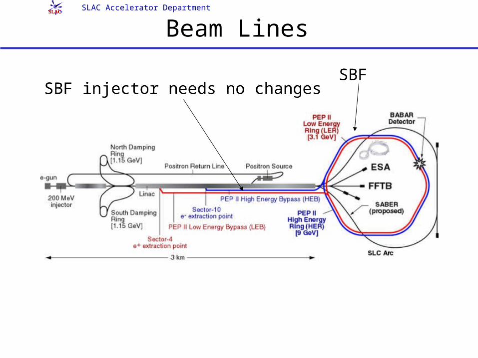
Beam Lines
SBFSBF injector needs no changes
SLAC Accelerator Department
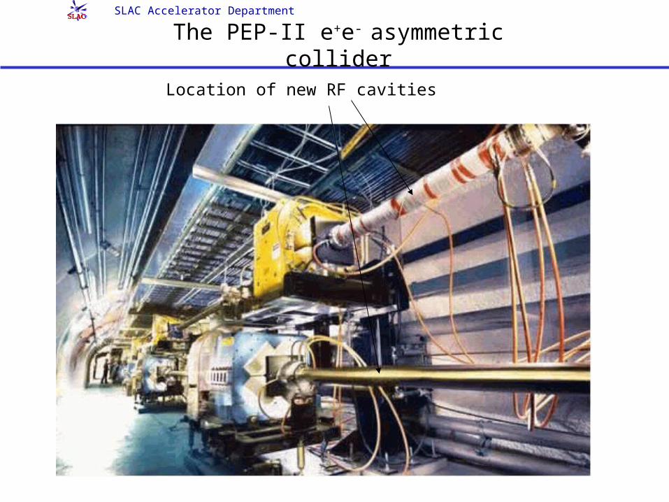
The PEP-II e+e- asymmetric collider
Location of new RF cavities
SLAC Accelerator Department
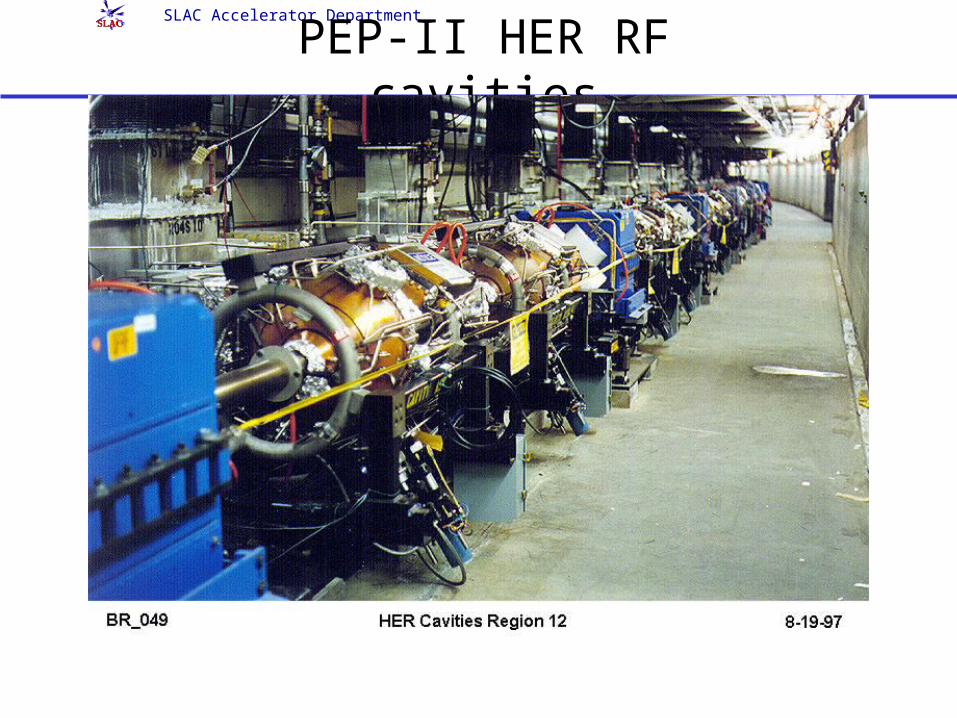
PEP-II HER RF cavities
SLAC Accelerator Department
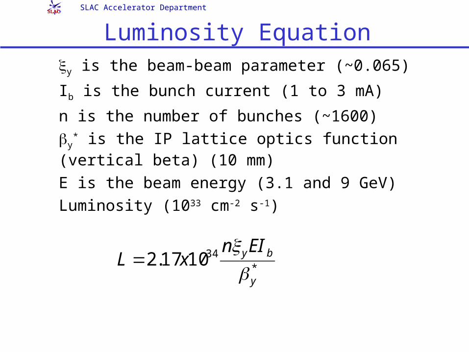
Luminosity Equation y is the beam-beam parameter (~0.065)
Ib is the bunch current (1 to 3 mA)
n is the number of bunches (~1600) y
* is the IP lattice optics function (vertical beta) (10 mm)
E is the beam energy (3.1 and 9 GeV) Luminosity (1033 cm-2 s-1)
*341017.2
y
byEInxL
SLAC Accelerator Department
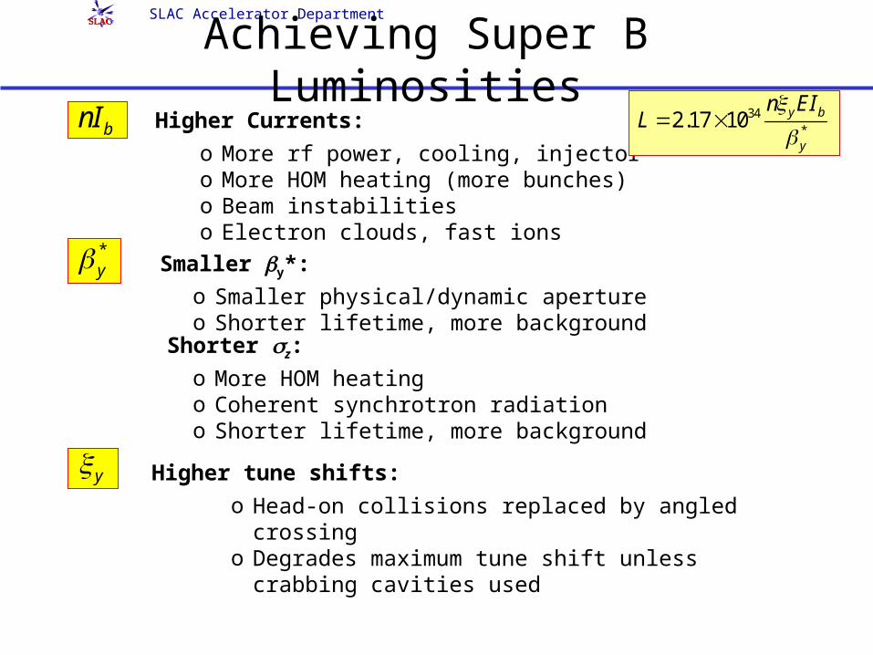
Achieving Super B Luminosities bnI Higher Currents:
o More rf power, cooling, injectoro More HOM heating (more bunches)o Beam instabilitieso Electron clouds, fast ions
* y Smaller y*:o Smaller physical/dynamic apertureo Shorter lifetime, more background
Shorter z:
o More HOM heatingo Coherent synchrotron radiationo Shorter lifetime, more background
y Higher tune shifts:
o Head-on collisions replaced by angled crossing
o Degrades maximum tune shift unless crabbing cavities used
34*
2.17 10 y b
y
n EIL
SLAC Accelerator Department
PEP-II/BaBar Roadmap: Super B-Factory Study
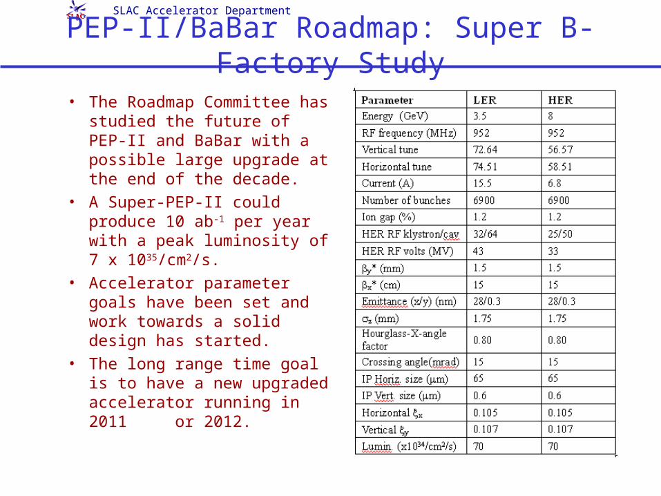
• The Roadmap Committee has studied the future of PEP-II and BaBar with a possible large upgrade at the end of the decade.
• A Super-PEP-II could produce 10 ab-1 per year with a peak luminosity of 7 x 1035/cm2/s.
• Accelerator parameter goals have been set and work towards a solid design has started.
• The long range time goal is to have a new upgraded accelerator running in 2011 or 2012.
SLAC Accelerator Department
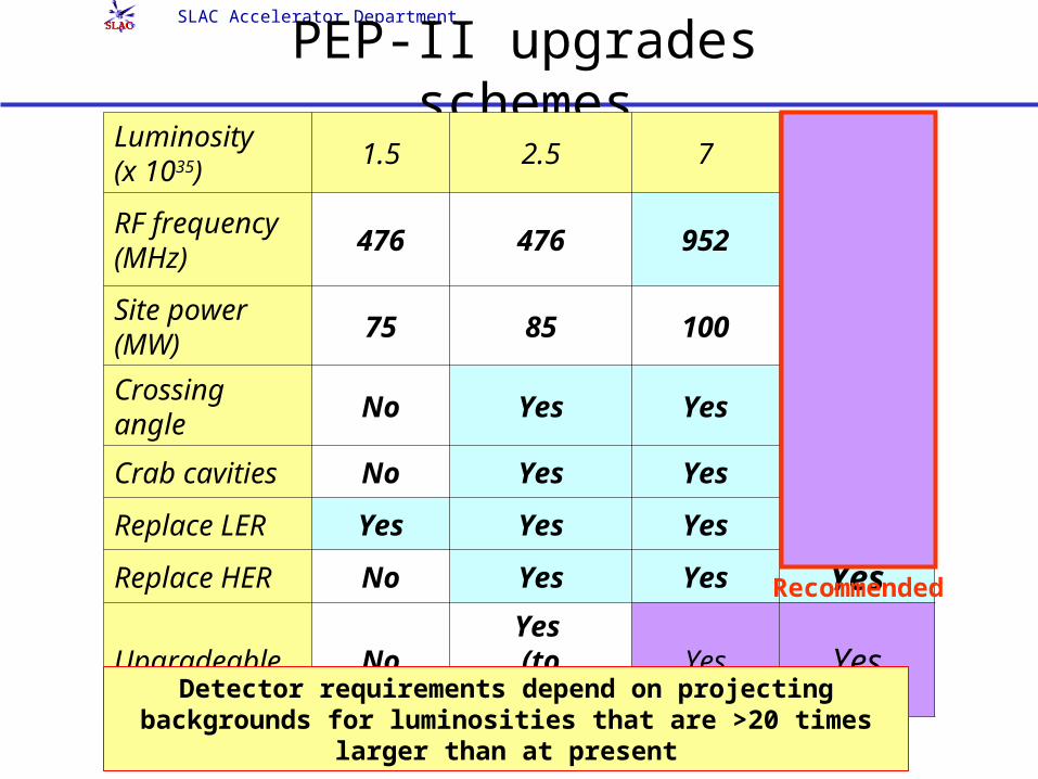
PEP-II upgrades schemesLuminosity (x 1035)
1.5 2.5 7 57
RF frequency (MHz)
476 476 952 476952
Site power (MW)
75 85 100 70100
Crossing angle No Yes Yes Yes
Crab cavities No Yes Yes Yes
Replace LER Yes Yes Yes Yes
Replace HER No Yes Yes Yes
Upgradeable NoYes
(to 952MHz)Yes Yes
Detector requirements depend on projecting backgrounds for luminosities that are >20 times
larger than at present
Recommended
SLAC Accelerator Department
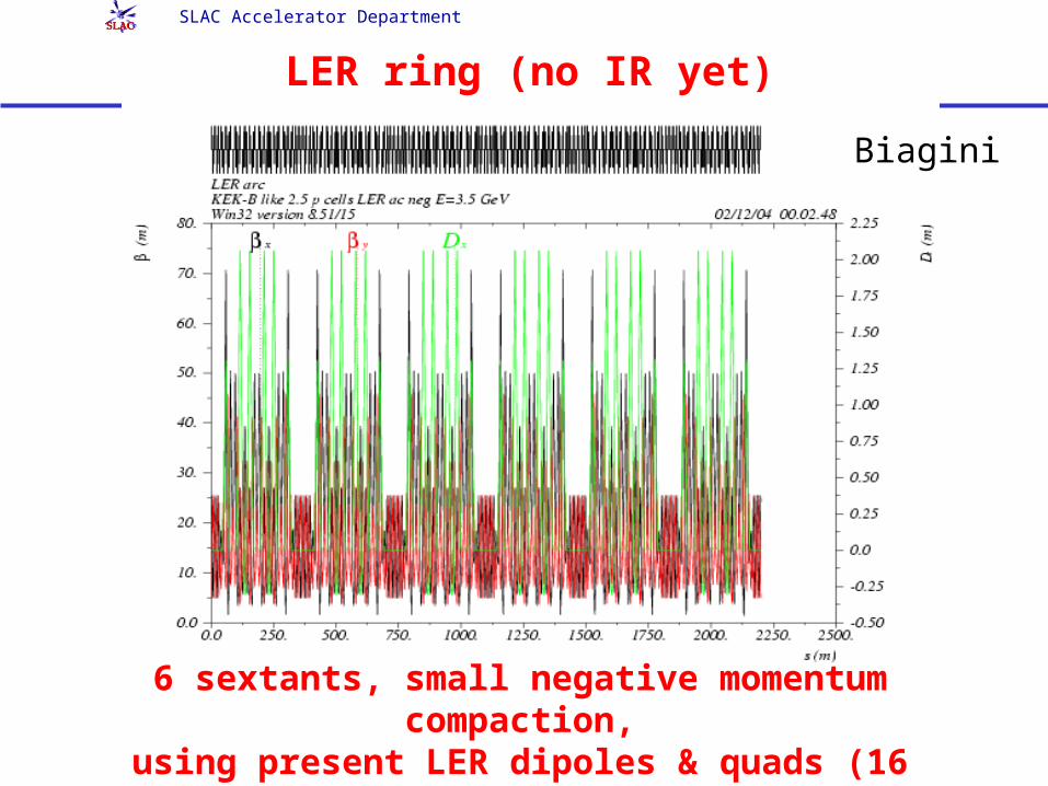
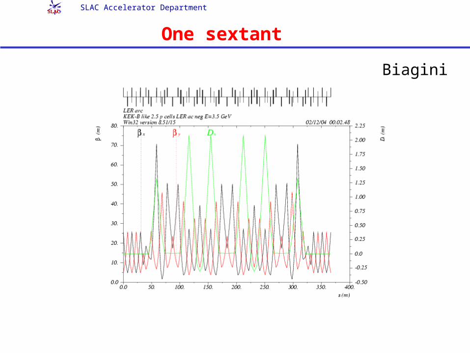
LER ring (no IR yet)
6 sextants, small negative momentum compaction,using present LER dipoles & quads (16 families),
3 sextupole families
Biagini
SLAC Accelerator Department
One sextant
Biagini
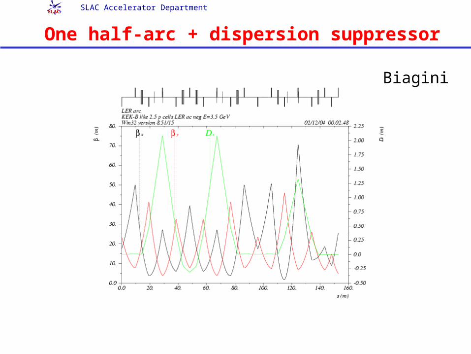
SLAC Accelerator Department
One half-arc + dispersion suppressor
Biagini
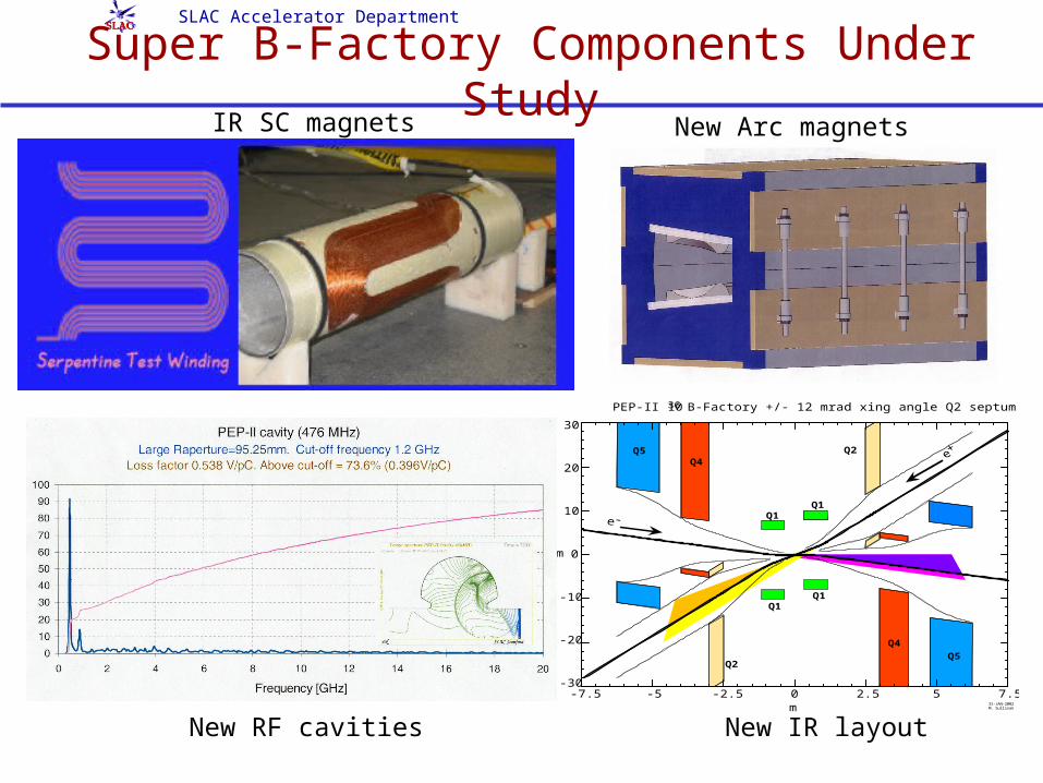
SLAC Accelerator Department
Super B-Factory Components Under Study
•
PEP-II 1036 B-Factory +/- 12 mrad xing angle Q2 septum at 2.5 m
30
20
10
0
-10
-20
-30
cm
-7.5 -5 -2.5 0 2.5 5 7.5m 31-JAN-2002
M. Sullivan
Q1
Q1Q1
Q1
Q2
Q4
Q5Q2
Q4Q5
IR SC magnets
New RF cavities New IR layout
New Arc magnets
SLAC Accelerator Department
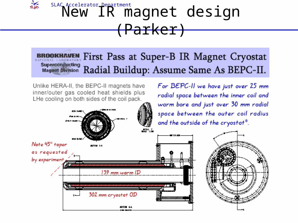
New IR magnet design (Parker)
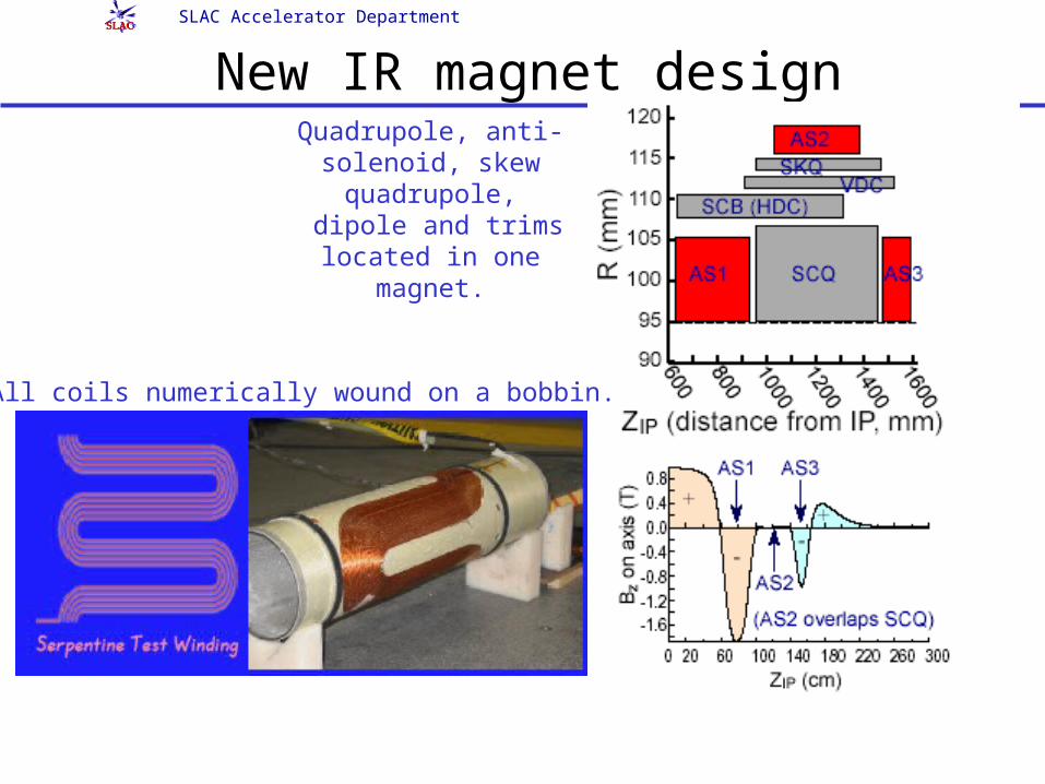
SLAC Accelerator Department
New IR magnet designQuadrupole, anti-
solenoid, skew quadrupole,
dipole and trims located in one
magnet.
All coils numerically wound on a bobbin.
SLAC Accelerator Department
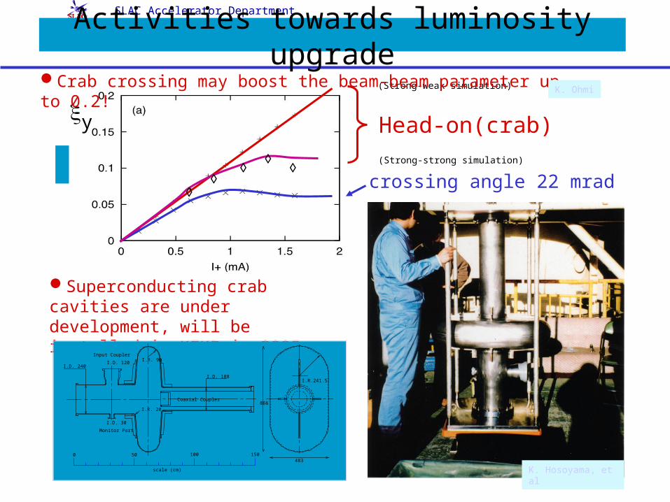
Activities towards luminosity upgrade
crossing angle 22 mrad
Head-on(crab)
◊
◊◊
◊◊
y
(Strong-weak simulation)
(Strong-strong simulation)
Crab crossing may boost the beam-beam parameter up to 0.2!
Superconducting crab cavities are under development, will be installed in KEKB in 2005.
I.R. 20
I.R. 90
I.D. 188
I.D. 120
I.D. 30
I.D. 240
Input Coupler
Monitor Port
I.R.241.5
483
866Coaxial Coupler
scale (cm)
0 50 100 150
K. Ohmi
K. Hosoyama, et al
SLAC Accelerator Department
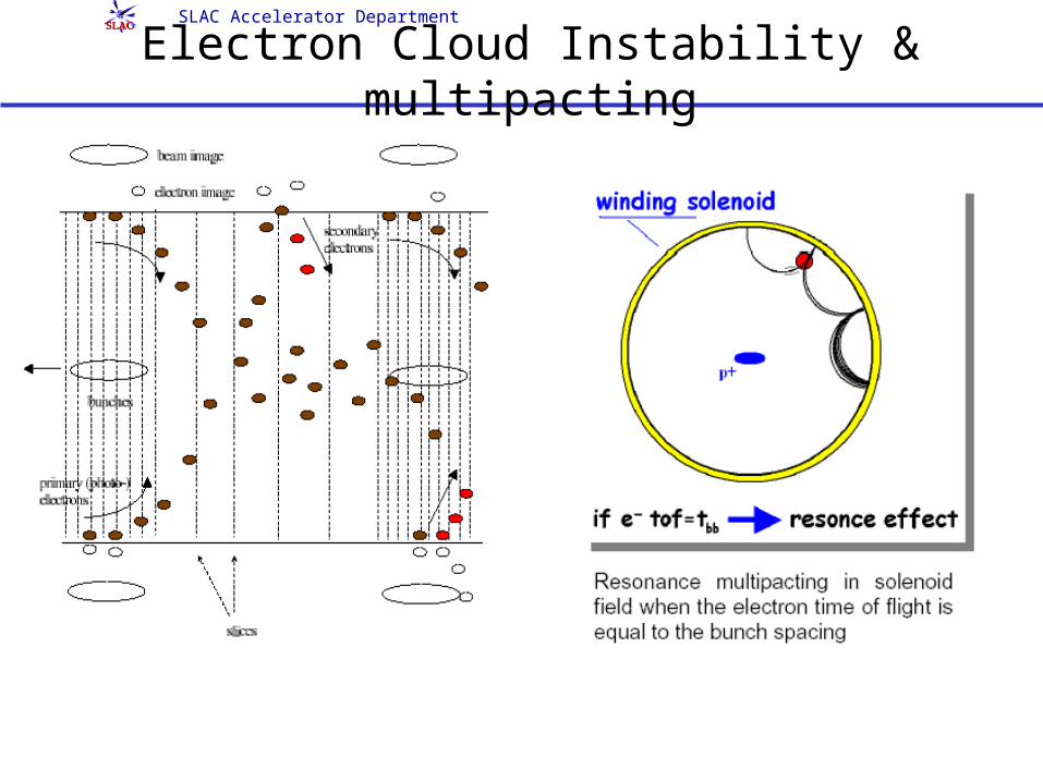
Electron Cloud Instability & multipacting
SLAC Accelerator Department
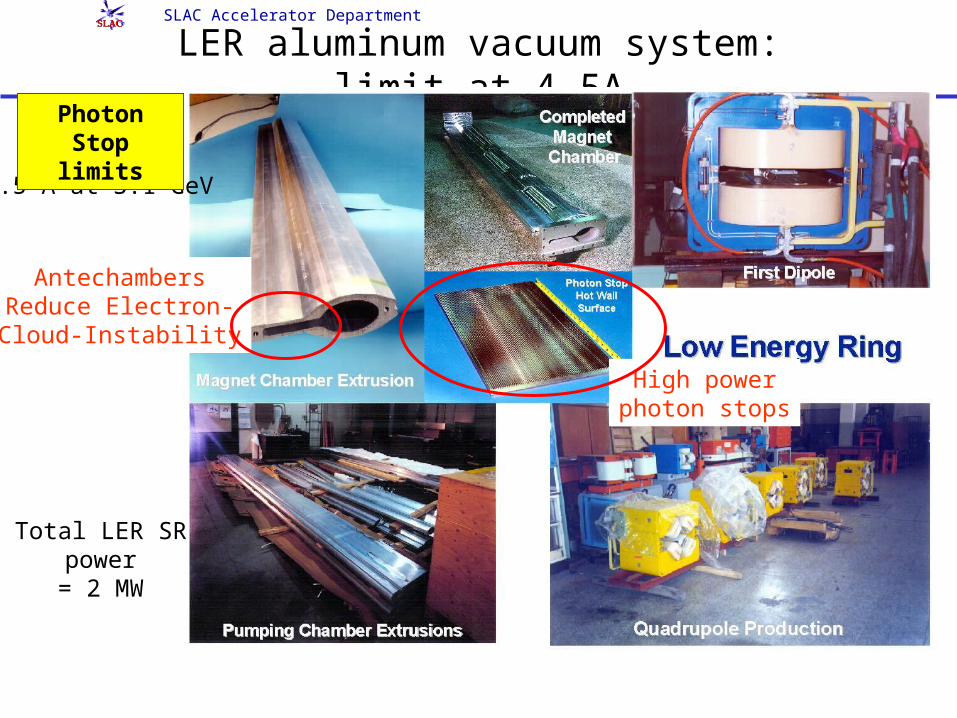
LER aluminum vacuum system: limit at 4.5A
Total LER SR power
= 2 MW
High powerphoton stops
AntechambersReduce Electron-Cloud-Instability
4.5 A at 3.1 GeV
Photon Stop limits
SLAC Accelerator Department
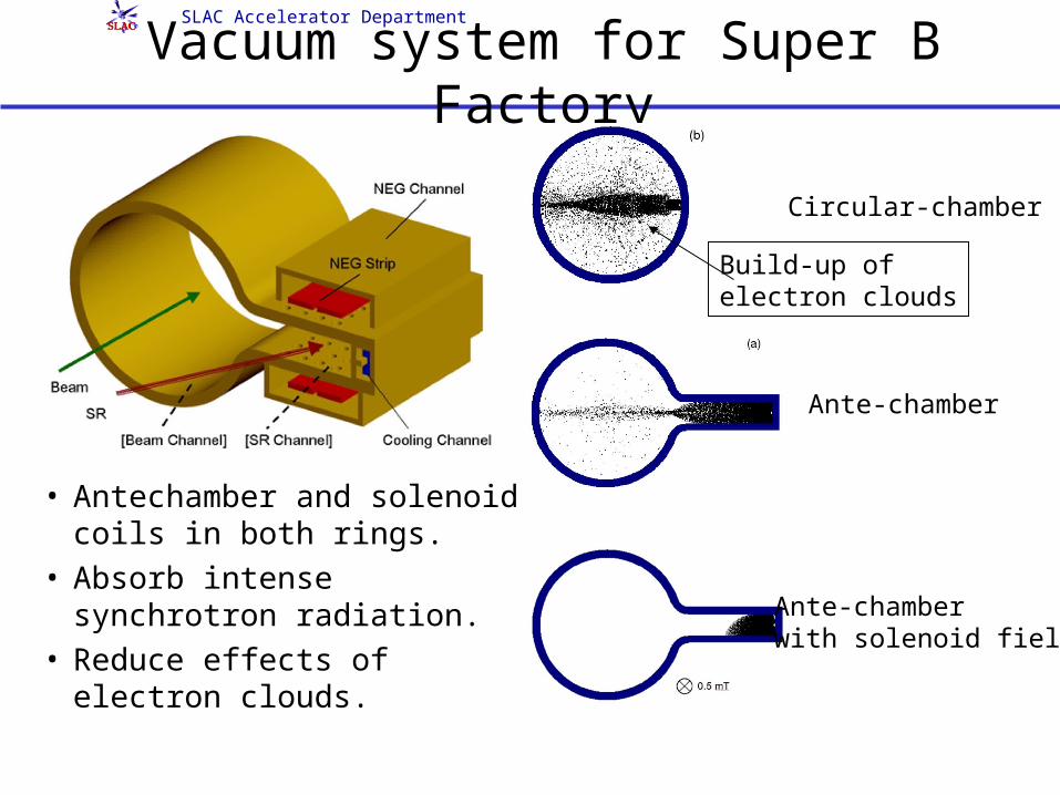
Vacuum system for Super B Factory
• Antechamber and solenoid coils in both rings.
• Absorb intense synchrotron radiation.
• Reduce effects of electron clouds.
Circular-chamber
Ante-chamber
Ante-chamberwith solenoid field
Build-up ofelectron clouds
SLAC Accelerator Department
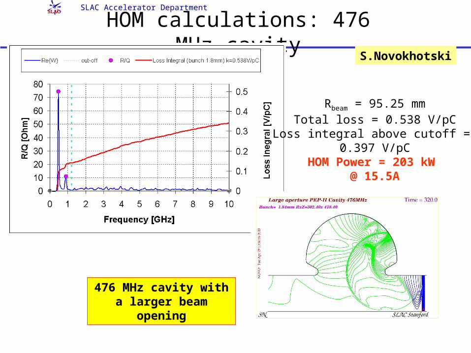
HOM calculations: 476 MHz cavity
476 MHz cavity with a larger beam
opening
S.Novokhotski
Rbeam = 95.25 mmTotal loss = 0.538 V/pC
Loss integral above cutoff = 0.397 V/pC
HOM Power = 203 kW @ 15.5A
SLAC Accelerator Department
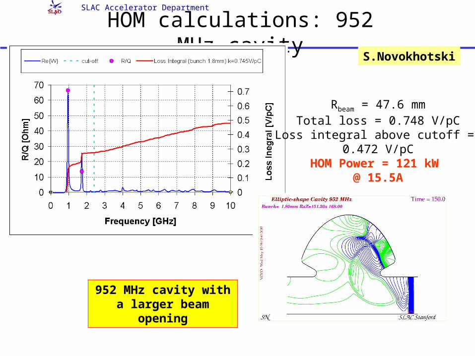
HOM calculations: 952 MHz cavity
952 MHz cavity with a larger beam
opening
S.Novokhotski
Rbeam = 47.6 mmTotal loss = 0.748 V/pC
Loss integral above cutoff = 0.472 V/pC
HOM Power = 121 kW @ 15.5A
SLAC Accelerator Department
87.57
6.56
5.5
4
3.532.5
21.51
0.5
4.55
HER Radiative Bhabhas
-7.5 -5 -2.5 0 2.5 5 7.5
0
10
20
30
-10
-20
-30
m
cm
M. SullivanFeb. 8, 2004API88k3_R5_RADBHA_TOT_7_5M
3.1 G
eV
3.1 G
eV
9 GeV
9 GeV
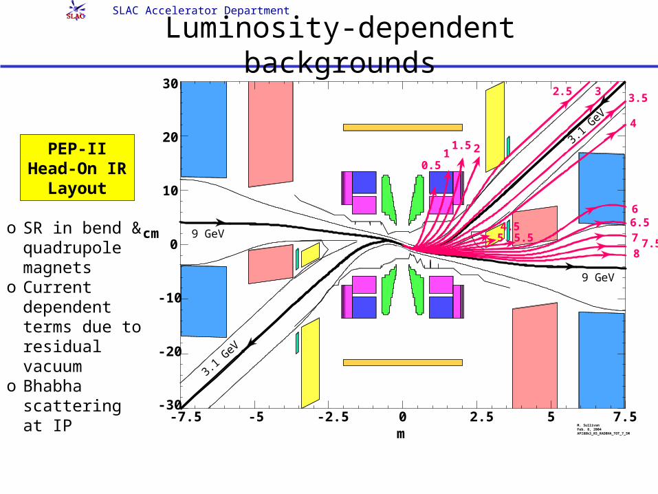
Luminosity-dependent backgrounds
o SR in bend & quadrupole magnets
o Current dependent terms due to residual vacuum
o Bhabha scattering at IP
PEP-II Head-On IR Layout

SLAC Accelerator Department
Achieving Super B Luminosities bnI Higher Currents:
o More rf power, cooling, injectoro More HOM heating (more bunches)o Beam instabilitieso Electron clouds, fast ions
* y Smaller y*:o Smaller physical/dynamic apertureo Shorter lifetime, more background
Shorter z:
o More HOM heatingo Coherent synchrotron radiationo Shorter lifetime, more background
y Higher tune shifts:
o Head-on collisions replaced by angled crossing
o Degrades maximum tune shift unless crabbing cavities used
34*
2.17 10 y b
y
n EIL
SLAC Accelerator Department
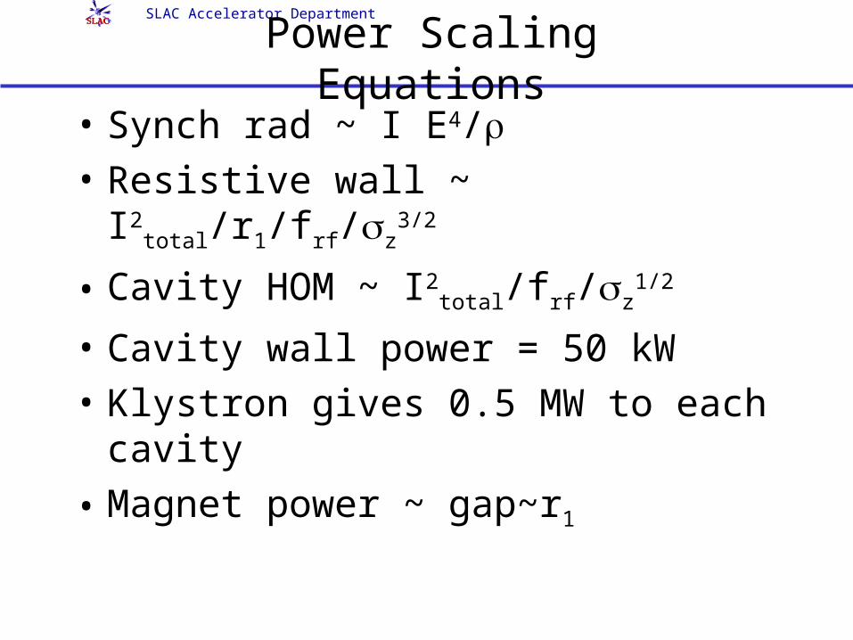
Power Scaling Equations
• Synch rad ~ I E4/• Resistive wall ~ I2
total/r1/frf/z3/2
• Cavity HOM ~ I2total/frf/z
1/2
• Cavity wall power = 50 kW
• Klystron gives 0.5 MW to each cavity
• Magnet power ~ gap~r1
SLAC Accelerator Department
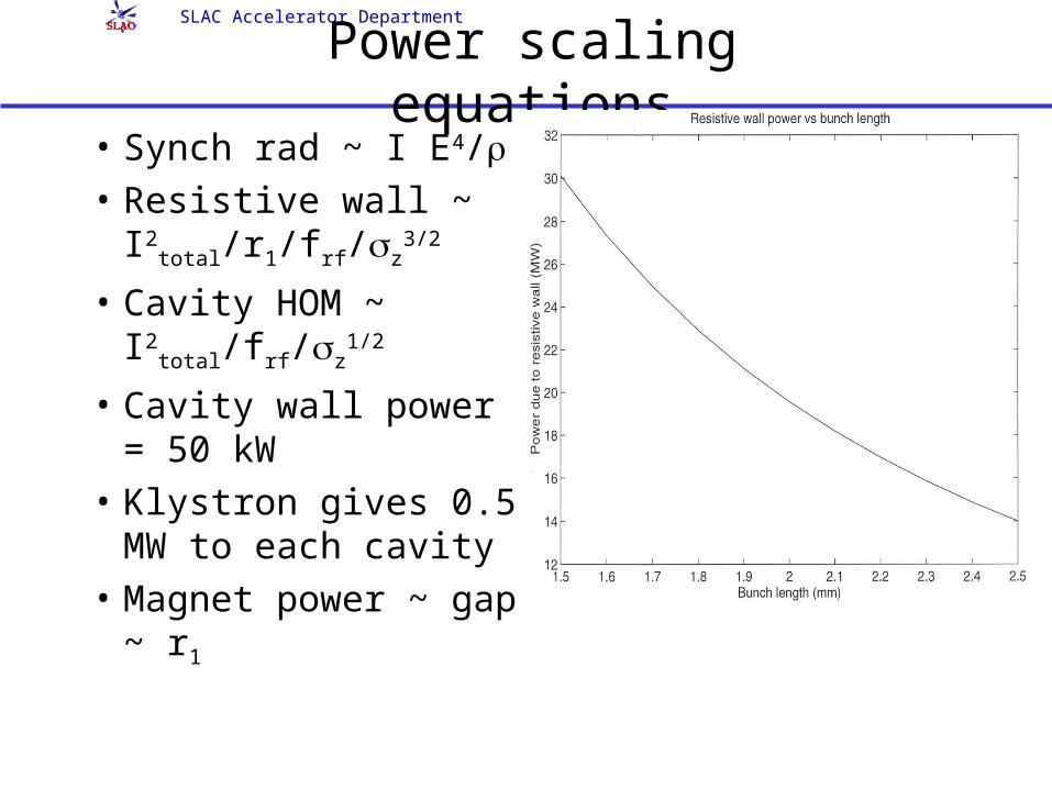
Power scaling equations• Synch rad ~ I E4/• Resistive wall ~
I2total/r1/frf/z
3/2
• Cavity HOM ~ I2
total/frf/z1/2
• Cavity wall power = 50 kW
• Klystron gives 0.5 MW to each cavity
• Magnet power ~ gap ~ r1
SLAC Accelerator Department
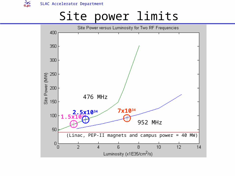
Site power limits
476 MHz
952 MHz
(Linac, PEP-II magnets and campus power = 40 MW)
1.5x10342.5x1034 7x1034
SLAC Accelerator Department
Recommended scenario: 5 to 7 x 1035
• Replace present RF with 952 MHz frequency over period of time.
• Use 8 x 3.5 GeV with up to 15.5 A x 6.8 A.• New LER and HER vacuum chambers with antechambers
for higher power (x 4). • Keep present LER arc magnets but add magnets to soften
losses; replace HER magnets as well.• New bunch-by-bunch feedback for 6900 bunches (every
bucket) at 1 nsec spacing. (Presently designing feedback system being 0.6-0.8 nsec spacing.)
• Push y* to 1.5 mm: need new IR (SC quadrupoles) with
15 mrad crossing angle and crab cavities
SLAC Accelerator Department
Important Factors in Upgrade Direction• Project is “tunable”
– Can react to physics developments
– Can react to changing geopolitical situation
• Project anti-commutes with linear collider
• Will emerge from BABAR and Belle, but could be attractive to wider community in context of other opportunities
– As we learn more about machine and detector requirements and design, can fine tune goals and plans within this framework
• Project has headroom
– Major upgrades to detector and machine, but none contingent upon completing fundamental R&D
– Headroom for detector up to 5 x 1035; with thin pixels beyond
– Headroom for machine up to 8.5 x 1035; requires additional rf, which can be staged into machine over time
SLAC Accelerator Department
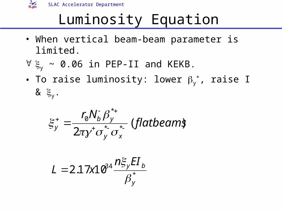
Luminosity Equation • When vertical beam-beam parameter is limited. y ~ 0.06 in PEP-II and KEKB.
• To raise luminosity: lower y*, raise I & y.
)(2 **
*0 flatbeamsNr
xy
yby
*341017.2
y
byEInxL
SLAC Accelerator Department
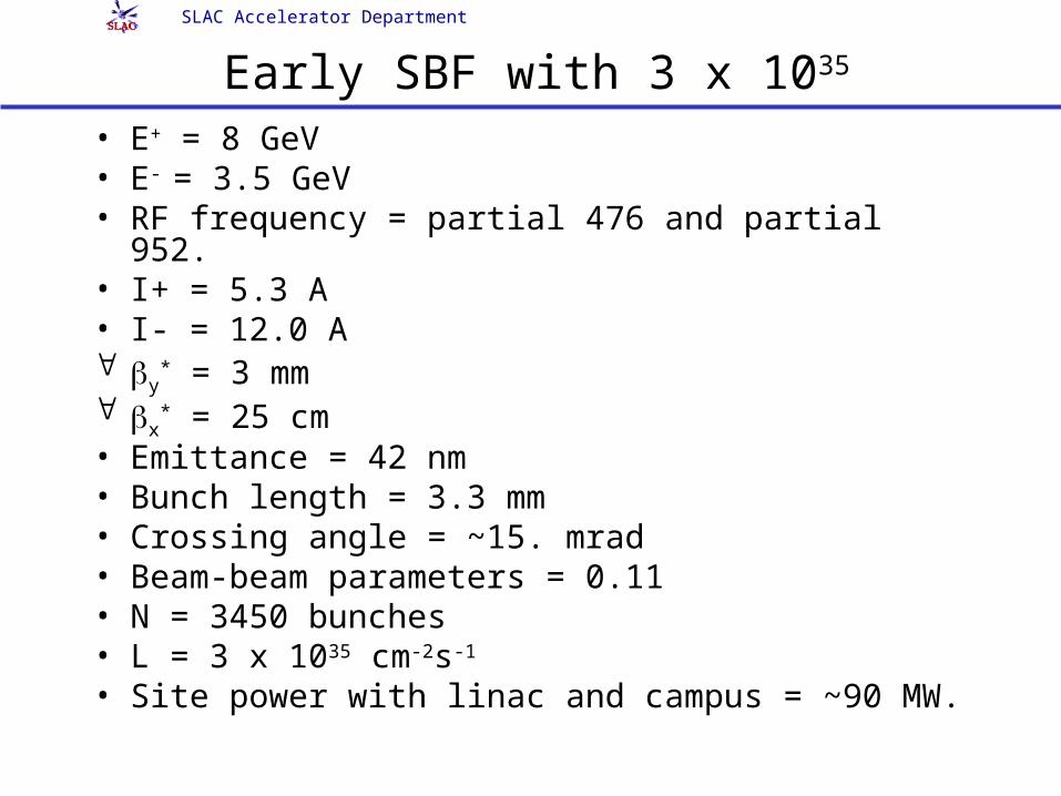
Early SBF with 3 x 1035
• E+ = 8 GeV• E- = 3.5 GeV• RF frequency = partial 476 and partial 952.• I+ = 5.3 A• I- = 12.0 A y
* = 3 mm x
* = 25 cm• Emittance = 42 nm• Bunch length = 3.3 mm• Crossing angle = ~15. mrad• Beam-beam parameters = 0.11• N = 3450 bunches• L = 3 x 1035 cm-2s-1
• Site power with linac and campus = ~90 MW.
SLAC Accelerator Department
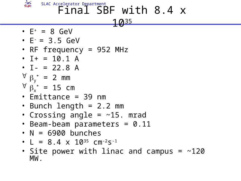
Final SBF with 8.4 x 1035
• E+ = 8 GeV• E- = 3.5 GeV• RF frequency = 952 MHz• I+ = 10.1 A• I- = 22.8 A y
* = 2 mm x
* = 15 cm• Emittance = 39 nm• Bunch length = 2.2 mm• Crossing angle = ~15. mrad• Beam-beam parameters = 0.11• N = 6900 bunches• L = 8.4 x 1035 cm-2s-1
• Site power with linac and campus = ~120 MW.
SLAC Accelerator Department
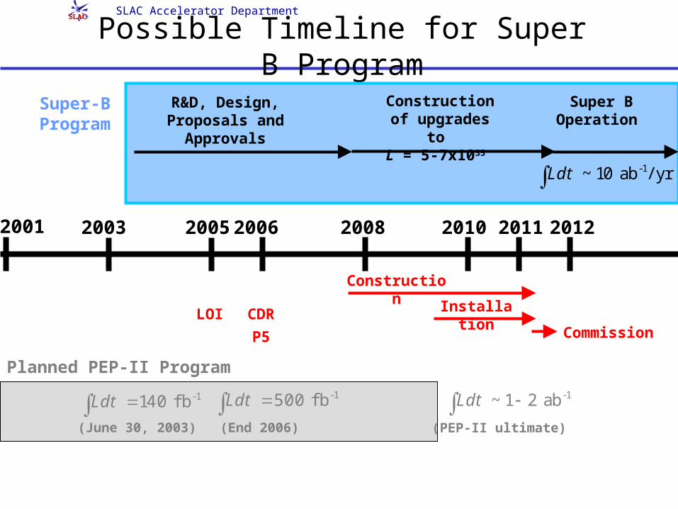
Possible Timeline for Super B Program
LOI
Construction of upgrades to L = 5-7x1035
-1~10 ab / yrLdt
Super-B Program
CDR Installation
R&D, Design, Proposals and
Approvals
P5
Construction
2001 2003 2010200820062005
Planned PEP-II Program
-1140 f bLdt -1500 f bLdt -1~1 2 abLdt
(June 30, 2003) (End 2006) (PEP-II ultimate)
Commission
2012
Super B Operation
2011
SLAC Accelerator Department
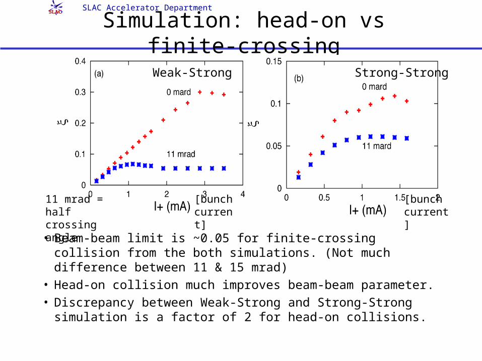
Simulation: head-on vs finite-crossing
• Beam-beam limit is ~0.05 for finite-crossing collision from the both simulations. (Not much difference between 11 & 15 mrad)
• Head-on collision much improves beam-beam parameter.• Discrepancy between Weak-Strong and Strong-Strong
simulation is a factor of 2 for head-on collisions.
Weak-Strong Strong-Strong
11 mrad = half crossing angle
[bunch current]
[bunch current]
SLAC Accelerator Department
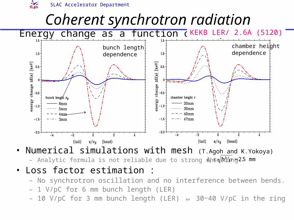
Coherent synchrotron radiation
• Numerical simulations with mesh (T.Agoh and K.Yokoya)
– Analytic formula is not reliable due to strong shielding.
• Loss factor estimation :– No synchrotron oscillation and no interference between bends.– 1 V/pC for 6 mm bunch length (LER)– 10 V/pC for 3 mm bunch length (LER) ⇔ 30~40 V/pC in the ring
Energy change as a function of z/zKEKB LER/ 2.6A (5120)
c h3 2.5 mm
bunch length dependence
chamber height dependence
SLAC Accelerator Department
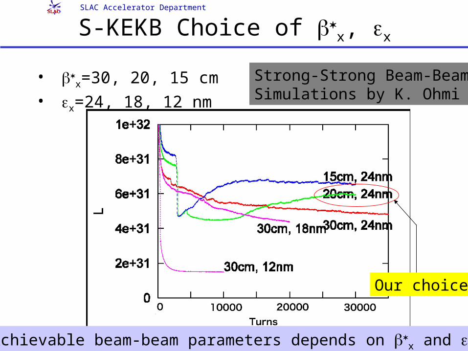
S-KEKB Choice of x, x
• x=30, 20, 15 cm
• x=24, 18, 12 nm
Strong-Strong Beam-BeamSimulations by K. Ohmi
Our choice
Achievable beam-beam parameters depends on x and x.
SLAC Accelerator Department
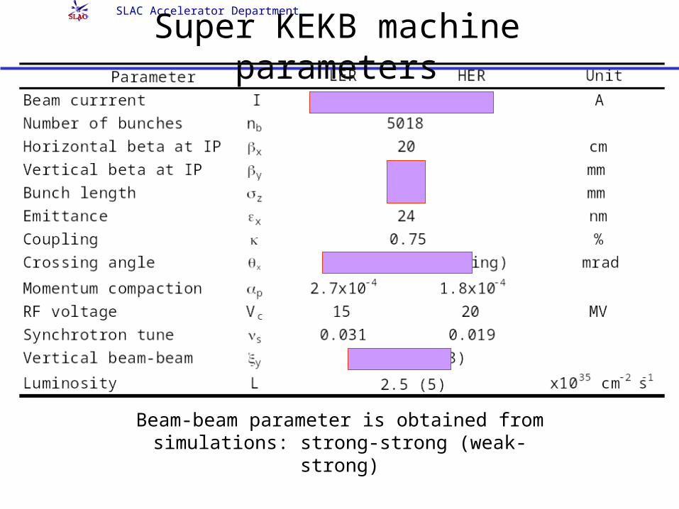
Super KEKB machine parameters
Beam-beam parameter is obtained from simulations: strong-strong (weak-strong)