Embed Size (px)
Citation preview
2004 5th Asian Control Conference
Sliding-Mode Tracking Control of the Stewart Platform Chin-I Huangl, Chih-Fu Chang', Ming-Yi Yu' and Li-Chen Fu"'
Department of Electrical Engineering' National Taiwan University, Taipei, Taiwan, R.Q.C.
E-mail: d992 [email protected]
Department of Electrical Engineering' Department of Computer Science and Information Engineerin$
National Taiwan University, Taipei, Taiwan, R.O.C. E-mail: [email protected],tw
Abstract
This paper presents a sliding mode control approach for the motion control of a Stewart platform. The control scheme is proposed given that the overall system parameters are subject to uncertainties while only the positions and velocities of links are measurable. To achieve high performance tracking control of a 6 DOF Stewart platform normally requires the full knowledge of the system dynamics. In this paper, some important properties of the dynamics of the Stewart platform have been derived and expIoited to develop a sliding-mode controller which can drive the motion tracking error to zero asymptotically. Stability analysis based on Lyapunov theory is performed to guarantee that the controller design is stable. Finally, the experimental results confirm the effectiveness of our control design.
&words- Stewart Platform, Paralfel Manipulators, Sliding Mode Control
1 Introduction
In recent years, the parallel link manipulators .have attracted much attention and many studies have been done on the kinematics or static analysis o f the parallel link manipulators [ 121. Generally speaking, the parallel link manipulators provide better accuracy, higher rigidity, higher load-to-weight ratio, and more uniform load distribution than the serial manipulators. Such advantages of fully paralle1 manipulators [I] originate from the fact that the actuators act in parallel sharing the common payload. The Stewart platform manipulator is a 6DOF mechanism with two bodies connected together by six extensible legs [l, 21. This closed-loop structure makes the manipulator system far more rigid in proportion to size and weight than any serial link robot, and yields a force-output-to- manipulator-weight ratio more than one order of magnitude greater than serial link robot. Practical usage of the Stewart platform manipulator has generally been in the area of low speed and large payload conditions such as motion base of
the classical automobile or flight simulator, and motion bed of a machine tool [4]. For the design and the control of the Stewart platform manipulators, dynamics analysis is a crucial step. In recent years, many research works have been conducted on the dynamics of the Cough-Stewart platform manipulator [3-111. Several methods such as the Lagrange equation, Newton-Euler equation and principle of virtual work are proposed to derive dynamic equations of the Gough-Stewart platform. The Lagrange formulation is well structured and can be expressed in closed form, but a large amount of symbolic computation is needed to find partial derivatives of the Lagrangian in this method. The Newton-Euler approach requires computation of all constraint forces and moments between the links. However, these computations are not necessary for the simulation and control of a manipulator.
The method of virtual work is an efficient approach to derive dynamic equations for the inverse dynamics of the Stewart platform [S, 91. However, for the forward dynamics, the method of virtual work is not straightforward because of the complicated velocity transform between the joint-space and task-space.
In this paper, an approach based on a sliding-mode control technique has been successfully developed for motion control of the Stewart platform system with having parametric uncertainty. These schemes are designed to guarantee practical robustness and stability. The remainder of this article is organized as follows: The kinematics and dynamics models for the Stewart platform are discussed in Section 2. In Section 3 the sIiding mode controller for a Stewart platform system is developed and the stability analysis is conducted. Section 4 shows some experimental results on controlling a realistic Stewart platform. Finally, some conclusions are made in Section 5.
2 Kinematics and Dynamics of a Stewart Platform
The Stewart Platform is a parallel manipulator [ I , 21. It has a lower base platform and an upper payload platform
562
connected by six extensible legs with ball joints at both ends. In the following subsections, we fvst make the inverse kinematics analysis of the Stewart platform, and then derive its dynamics.
2.1 Inverse and Forward Kinematics Analysis of a Stewart Platform The Stewart platform has parallel actuators in contrast to
the traditional manipulator arm equipped with serial actuators. The coordinates to represent the 6 DOF motion are the inertial frame and the moving frame attached to moving platform. The 6 DOF motions are linear and angular motions. Linear motions consist of the longitudinal (surge), lateral(sway), and vertical(heave) motion. Whereas angular motions are expressed as Eulerian angle rotations with respect to x-axis, y-axis, and z-axis, i.e. roll, pitch and yaw, in sequence.
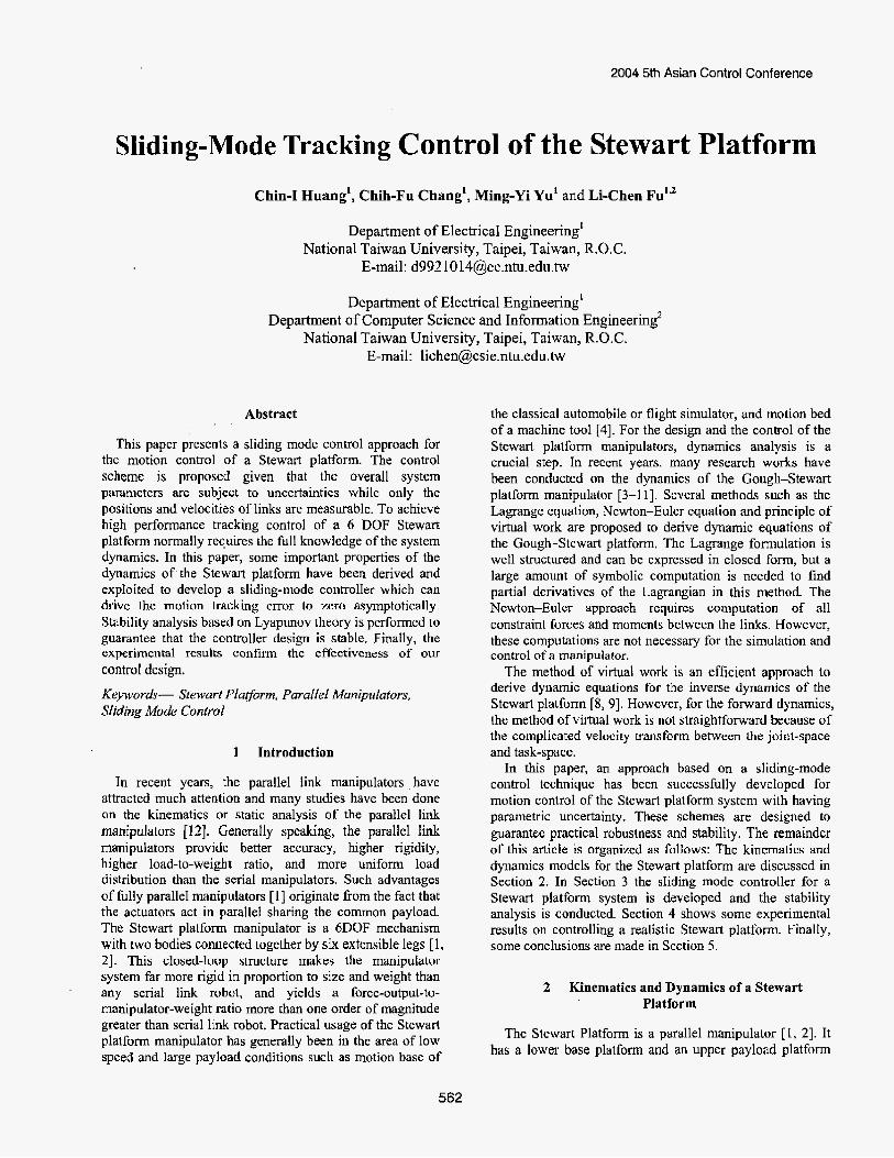
The inverse kinematics are mathematics treating the problem of describing the postion and orientation of the payload platform in terms of the actuator variables, i.e., to express (x, y , z , a, j, y ) by the actuator lengths l i , i = 1 , 2 , . - - , 6 . As the sketch map shown in Fig. 1, we attach two coordinate h m e s {P) and {B) to the payload platform and the base platform, respectively. Suppose that
vector 4 = [ p , p3y p , , IT describes the postion of the
reference point 4 shown in Fig, l(a) with respect to frame (P}. Then, < can be expressed as
.s L
Ai = A;-, + 8, i = 2,4,6 where rp is radius of the upper plate and in our case
?I 8, =- L
On the other hand, the vector B, = [b, be b,]’ in Fig.
l(a) describes the postion of the attachment point Bi with respect to frame {B), where Bi can be expressed as
A, = A,-l +Ob i = 2,4,6 again, r8 is radius of the lower plate, and in our case
IT # ‘ - 6
Fig. l(b) Sketch Map foxhe Stewart Platform Now, let orientation matrix R represent the orientation
of the frame {P} with respect to the frame {B), as being expressed as:
c a c p caspsy-sacy caspcy+sasy
where ca I C O S Q and sa ~ s i n a . By adopting proper coordinate transformation, the actuator vector Li corresponding to the actuator leg i w.r.t. h m e {B} can be derived as:
(2 ) Li = R-T -b P - B, for i = 1,2,-.. ,6,
563
where P = [ x y z]‘ . Since the actuator length is
1, = IIL, )I , we can obtain complete solution of the inverse kinematics as followed:
1,2 = r 2 + y 2 + z 2 + ~ ~ 2 + r ~ 2 + 2 ( ~ 1 ~ c r + 1 ; 2 p ~ ) ( X - b e )
+ 2(r,,PD + WT )(Y - by) f 2 h P W + %PiY )z
-2(x*b, +y.b,) for i= 1,2,.-.,6, (3) where rp and r, represent the radius of the payload platform and that of the base platforms, respectively.
The forward kinematics of Stewart platform the 6 DOF motions of the upper payload platform the link length variables, which plays important role for the MIMO control or the motion visualization of the Stewart platform, but unfortunately it is difficult to come by because of the nonlinearity and complexity. Although the Newton Raphson method, is a popular technique to solve the derivation problem, it suffers from repetitive steps before solution convergence and hence fails to become a real-time solution. Moreover, such method may ever lead to infinite loop provided wrong selection of the initial values. Nevertheless, the general from of expression can be made as follows: f ; (x , y , z, a, p, y ) = x2 + J + z2 + r,‘ + r; + 2(r,,% + 1;&)(x --BJ
+ 2(r,,p, +aP,1Cv-q + 2(131% +r,,%)z -2(x-Bu + y . B,)-Iz2 =O (i =1,2, ..., 4)
2.2 Dynamics Analysis of Stewart Ptatform To design a system with high operational performance, a
sound control method is crucially needed. However, to control the Stewart Platform system well is very challenging due to the high nonlinearity in system dynamics, system uncertainties, and complex kinematics. In general, the dynamic equations [4] of the Stewart Platform system can be written as:
M ( q ) 4 +. C ( W M + Gfq) = JTs (4) where M ( q ) i s an 6 x 6 inertia matrix, which is a
symmetric and positive definite for all q E R 6 ; C(q,q)q is the CoriolislCentripetal vector; G(q) and r are 6 x 1 vectors containing gravity torques and input torques, respectively, Some pertaining properties are given below. Property 1: C(q,q) andA&q) are bounded functions if
q andq are bounded. C(q,q) is a bounded function if q, q and ij are bounded. Property 2: kf is a symmetric and positive defmite matrix. Moreover, for an appropriate choice of C, M - 2C can be a skew-symmetric matrix, which means that xT (k - 2C)x = 0, Vx E R” . This property is well known in the robotics literature.
We now investigate every component of the Stewart Platform dynamics. For notational simplicity, we use SC),
C(-) to stand for sin(.) and cos(.) , respectively, I ( - )
represent the inertia of the platform. Thus, the inertia matrix M(.) can be written as:
o m 0 0 0 0 m O O 0 0
O O O M , 0 Ma O I 0 0 0 MH Mss
where MM = rxc;c; + z,c;s; + rzs;, M,, = Ms4 = (Ir - I,)C,C,S, 3
M , = M H = IzSo,
M55 = IxS: + IyC:,
M66 = I,, and Corilois and Centrifugal Matrix C(.) can be explicitly
written as:
J =
where
subject to the following rotation mabices
564
3 Sliding-Mode Control Design
A sliding-mode controlIer is proposed in this section to drive the Stewart platform system such that the motion tracking errors asymptotically converge to zero, i.e.,
where q,(r) is the desired trajectory. Some notations are now introduced to simplify the derivation addressed later. Thus, define
q(') q d ( t ) , q(t) j as O3 9
ep = q d 0) - 4 ( 4 ep E R" 4, = ( A t ' p + q d ) , 4, ER"
where ep , q, denote the motion error and a set of auxiliary signals, respectively. Assume that the equations of motion are linear in terms of an appropriately selected set of constant parameters 8, i.e.,
where U(.) is an 6 x r matrix of known functions of q , q, qd, [ j d and qd ; B is an r-dimensional vector, containing the unknown or uncertain parameters. In the literature, 19 and Yare called the unknown parametric vector and the regression matrix, respectively. This assumption is sometimes considered as a linear parameterization property and is valid for robot manipulators [13].
The sliding surface s E R 6 , which is composed of motion error as well as force error, is defined as
(6) , Note that the motion tracking can be insured once the
sliding surface s can be well controlled. When s ( t ) = O , then to zero.
W r + Cqr + G = Y(q, 4, q d 9 q d 9 4d)Q ( 5 )
s = q, - q = Aep + ep
Aep + kP = 0, (7) ' and the standard linear control arguments assure that lim,+= gP, ep = 0. In a word, e,, ep converge to zero as r + w as long as s( t ) = 0 . In terms of the sliding surface, the error dynamics can be rewritten in the following form:
Mi = M(4, - i j )
= Mqr - Mq
= Mqr + Ccj + G - JT T (8)
r = J-'(Ksgn(s)+U(.)q7), (9) So, if one sets the control law T in the form
where the controller parameter K = diag{Kl, K,, ... ,&I, , 6; Y(.) is defined in Eq. (5); and K, > 0, I = 1, 2,
p=[q, p,] is the switching function designed according to the sliding-mode theory [ I I], as follows:,
J = I
with e 21 6'i I , then Eq. (8) can be rewritten as follows:
M = Mqr +C(q , -s)+G-J'r
= Y ( ) d - C ~ - K s g n ( s ) - Y(.)p. (10) A complete stability analysis of the error system is given after stating the following theorem. Theorem : Consider the closed-loop system defined by the controller, Eq. (9). Then the system trajectories reach the sliding surface s ( r )=O in finite time. In addition, q(t) and q(r) will asymptotically track q d ( f ) and qd(t) , respectively, as t + m , Proof: Consider the Lyapunov function candidate
1 v = -sTM. 2
The time derivative of V leads to 1 G = sTMS + -s 'Ms 2
= - ~ K , l s J + s = Y ~ - s ~ Y p 1.1
S - k K , l S , l 11 1) i = l
where Eq. (10) and Property 2 have been applied in the second equality. Hence, the trajectories will reach the sliding surface s=O in finite timc. Following the arguments below Eq. (7), it can be shown that ep and&p converge to
zero as c -+ 00 by Barbalat's lemma.
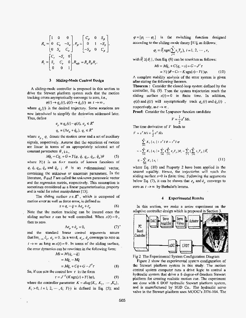
4 Experimental Results
In this section, we make a series experiment on the
Fig 2 The Experimental System Configuration Diagram Figure 2 show the experimental system configuration of
the Stewart platform system in this study. The motion control system computer runs a drive logic to control a hydraulic system that drive a 6 degree-of-freedom Stewart platform for creating realistic motion cue. The experiment are done with 6 DOF hydraulic Stewart platform system, and is manufactured by SGD Co.. The hydraulic servo valve in the Stewart platform uses MOOG'S JO76-104. The
565
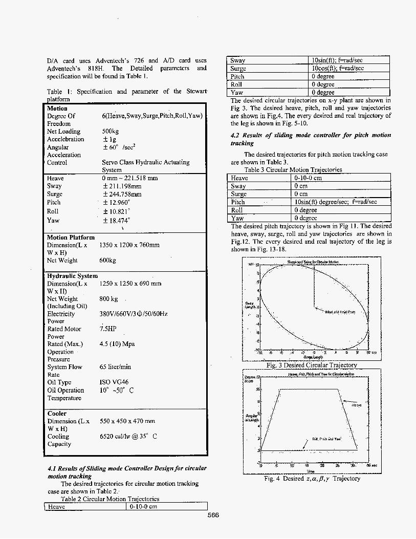
D/A card uses Adventech's 726 and A/D card uses Adventech's 818H. The Detailed parameters and specification will be found in Table 1.
Heave Sway Surge Pitch Roll Yaw
Table 1: Specification and parameter of the Stewart platform Motion Degree Of 6(Beave,Sway,Surge,Pitch,RoH,Yaw) Freedom Net Loading 500kg
Angular f 60" /secZ Acceleration Control Servo Class Hydraulic Actuating
AcceIebration * Ig
System Heave 0 KKII - 221.518 IIKII
Sway f 211.198mm Surge f 244.758mm Pitch f 12.960" Roll f 10.821' Yaw f 18.474"
8
0-10-0 cm 0 cm 0 cm lOsin(ft) degreehec; f+ad/sec 0 degree 0 degree
Motion Platform Dimension(L x
Net Weight 600kg
Hydraulic System
1350 x 1200 x 7 6 0 m W x H )
D&ension(L x
Net Weight (Including Oil) Electricity Power Rated Motor Power Rated (Max.) Operation Pressure System Flow Rate Oil Type Oil Operation Temperature
W x H ) ,
1250xl250x690mm
800 kg
3 XOV/660V/3 0 /50/60Hz
7.5HP
4.5 (10) Mpa
65 litedmin
IS0 VG46 10" -50" C
Cooler Dimension (L x W x H) Cooling Capacity
550 x 450 x 470 mm
6520 calihr @ 35" C
4. I Results of Sliding mode Controller Design for circular motion tracking
case are shown in Table 2: The desired trajectories for circular motion tracking
Fig. 3 Desired Circular Trajectory I ^___II
I 1 Fig. 4 Desired z , a, p , y Trajectory
Table 2 Circular Motion Trajectories LHeave 1 0-10-0 cm 1
566
Fig. 5 The Leuajectories .L Fig. 9 The Leg5 Trajectories P _LI_
Fig. 6 The Leg2 Trajectories ___r
r*rar Fig. 7 The Leg3 Trajectories
. Tart
Fig. 8 The Leg4 Trajectories Fig, 12 Desired x, y,z,a,y Trajectory 567
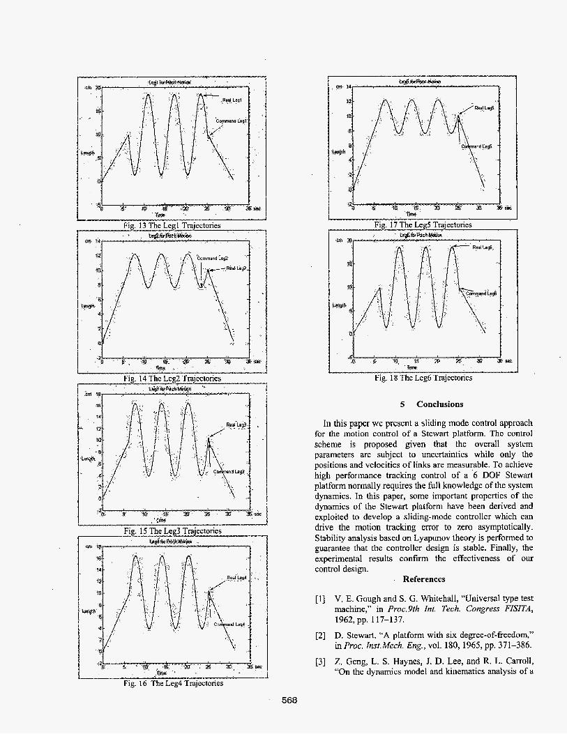
Fig. 16 The Leg4 Trajectories
t s r a x a as= r w
Fig. 17 The Leg5 Trajectories
5 Conclusions
In this paper we present a sliding mode control approach for the motion control of a Stewart platform. The control scheme is proposed given that the overall system parameters are subject to uncertainties while only the positions and velocities of links are measurable. To achieve high performance tracking control of a -6 DOF Stewart platform normally requires the full knowledge of the system dynamics. In this paper, some important properties of the dynamics of the Stewart platform have been dcrived and exploited to develop a sliding-mode controller which can drive the motion trackmg error to zero asymptotically. Stability analysis based on Lyapunov theory is performed to guarantee that the controller design is stable. Finally, the experimental results c o n f m the effectiveness of our control design.
I References
[ I ] V. E. Gough and S. G. Whitehall, "Universal type test machine," in Proc.9th Int. Tech. Congress FISITA,
D. Stewart, "A platform with six degree-of-freedom," in Proc. Inst.Mech. Eng., vol. 180, 1965, pp. 371-386.
Z. Geng, L. S . Haynes, 1. D. Lee, and R. L. Carroll, "On the dynamics model and kinematics analysis of a
1962, pp. 117-137.
[2]
[3]
568
class of Stewart platform,” Robot,Autonomous Syst.,
G. Lebret, K. Liu, and F. L. Lewis, “Dynamic analysis and control of a Stewart platform manipulator,” J. Robot. Syst., vol. 10, no. 5, pp.629-655, 1993.
W. Q. D. Do and D. C, H. Yang, “Inverse dynamic analysis and simulation of a platform type of robot,” J. Robot. Syst., vol. 5, no. 3, pp.209-227, 1998.
B. Dasgupta and T. S. Mmthyunjaya, “Closed-form dynamic equations of the General Stewart platform through the Newton-Euler approach,”Merh. Mach. Themy, vol. 33, no. 7,pp. 993-1012, 1998.
B. Dasgupta and T. S. Mruthyunjaya, “A Newton- Euler formulation for the inverse dynamics of the Stewart platform manipulator,” Mech. Much. Theoy, vol. 33, no. 8, pp, 1135-1 152, 1998.
C. D. Zhang and S. M. Song, “An efficient method for the inverse dynamics of manipulators based on the virtual work principle,” L Robot. Syst., vol. 10, no. 5,
J.Wang and C . M. Gosselin, “A new approach for the dynamic analysis of parallel manipulators,” MuItiho&
vol. 9, pp. 237-254, 1992,
pp. 605-627,1993.
Sy~t . Qw., vol. 2, pp. 3 17-334,1998.
[lo] K. E. Zanganek, R. Sinatra, and J. Angeles, “Kinematics and dynamics of a six-degree-of-freedom parallel manipulator with revolute legs,” Robot, vol.
(1 11 L. W. Tsai, “Solving the inverse dynamics of parallel manipulators by the principle of virtual work,” in 1998 ASME Design Eng. Tech. CQnf (DETC/MECH-5865), Sept. 1998, pp. 451457.
[I21 K. M. Lee and D. H. Shah, “Kinematics Analysis of a 3 DOF in Parallel Actuated Manipulator”, IEEE Journal of Robotics and Automation. Vol. 4, No. 3,
15, pp. 385-394,1997.
PP354-360, 1988.
[ 131 J.J.E. Slotine and W. Li. Applied Nonlinear Control. Englewood Cliffs, NJ: Prentice-Hall, 199 1.
569