Embed Size (px)
Citation preview
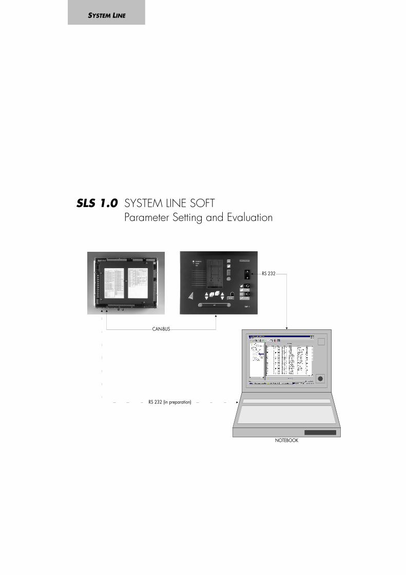
SLS 1.0 SYSTEM LINE SOFTParameter Setting and Evaluation
SYSTEM LINE
NOTEBOOK
RS 232
CAN-BUS
RS 232 (in preparation)
2 HB SLS1.0 E 02.00
Table of contents
1 Introduction................................................................................................................ 42 Application of the SYSTEM LINE SOFT .......................................................................... 63 Installation ................................................................................................................. 7
3.1 Hard- and software conditions...................................................................................................73.2 Installation of the SYSTEM LINE SOFT .........................................................................................7
4 De-installation ............................................................................................................ 85 Required configurations.............................................................................................. 9
5.1.1 Starting the programme � communication via RS232...............................................................95.1.2 Starting the programme - communication via CAN-BUS..........................................................105.1.3 Terminating the programme - communication via RS232 ........................................................115.1.4 Terminating the programme - communication via CAN-BUS ....................................................115.1.5 Configuration of the Communication Server for zero-modem operation......................................125.1.6 Configuration of the Communication Server for CAN-BUS operation.........................................13
6 Layout of the menu................................................................................................... 146.1 The button bar ......................................................................................................................156.2 Menu »File«..........................................................................................................................16
6.2.1 Choosing the language for the user surface .........................................................................176.3 Menu »Edit« .........................................................................................................................176.4 Menu »Parameters«................................................................................................................18
6.4.1 Copying a protective parameter set within the CSP ...............................................................186.4.2 Storing and loading parameter sets ....................................................................................206.4.3 Storing and loading single line diagrams ............................................................................21
6.5 Menu »Control« ....................................................................................................................216.6 Menu »Window« ..................................................................................................................226.7 Menu »Help« (in preparation) ..................................................................................................236.8 Menu »?« ............................................................................................................................24
7 The tree structure of the SYSTEM LINE SOFT ............................................................... 257.1 Measuring ...........................................................................................................................257.2 Statistics ..............................................................................................................................267.3 Event recorder ......................................................................................................................277.4 Fault recorder .......................................................................................................................287.5 I/O-Status ...........................................................................................................................29
7.5.1 Digital inputs..................................................................................................................297.5.2 Signal relays..................................................................................................................317.5.3 Service .........................................................................................................................327.5.4 Self-test .........................................................................................................................33
8 Parameter setting..................................................................................................... 348.1 Example 1: Changing the rated frequency (basic parameter).........................................................358.2 Example 2: Activating the C.B. failure protection ........................................................................368.3 Changing the protective parameter sets.....................................................................................37
9 Printing .................................................................................................................... 389.1 Preliminary printer settings .......................................................................................................389.2 Printing the active window ......................................................................................................389.3 Printing a complete branch inclusive of all submenus....................................................................38
10 Data recorder (optional) ......................................................................................... 3910.1 Introduction ........................................................................................................................3910.2 Hard- and software prerequisites............................................................................................3910.3 Installation of the data recorder..............................................................................................3910.4 De-installation of the data recorder .........................................................................................3910.5 Structure of the menu of the data recorder................................................................................40
10.5.1 Layout of the surface of the data recorder ..........................................................................4010.5.2 The button bar..............................................................................................................4110.5.3 Menu »File« .................................................................................................................42
HB SLS1.0 E 02.00 3
10.5.4 Menu »Preferences« ...................................................................................................... 4310.5.5 Menu »View«............................................................................................................... 46
10.6 Menu »Help« ..................................................................................................................... 4610.6.1 Starting the data recorder .............................................................................................. 47
10.7 The tree structure of the data recorder..................................................................................... 4810.7.1 Important information on the function of the mouse.............................................................. 4810.7.2 Adding channels to the operating window........................................................................ 4810.7.3 Zoom......................................................................................................................... 4910.7.4 Removing channels from the operating window.................................................................. 5110.7.5 Copying channels via the clipboard ................................................................................ 51
10.8 Display of the measured values on which the interpolated curve course is based ............................ 5110.8.1 Changing the colour of the channel display ...................................................................... 5110.8.2 Reading out the momentary values................................................................................... 52
11 Appendix I (cable assignment RS 232).....................................................................5312 Appendix II (communication links)...........................................................................5413 Appendix III (trouble-shooting) ................................................................................5614 Order Key ...............................................................................................................59
4 HB SLS1.0 E 02.00
1 Introduction
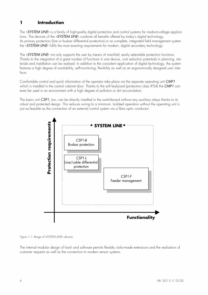
The »SYSTEM LINE« is a family of high-quality digital protection and control systems for medium-voltage applica-tions. The devices of the »SYSTEM LINE« combine all benefits offered by today's digital technology.As primary protection (line or busbar differential protection) or as complete, integrated field management systemthe »SYSTEM LINE« fulfils the most exacting requirements for modern, digital secondary technology.
The »SYSTEM LINE« not only supports the user by means of manifold, easily selectable protection functions.Thanks to the integration of a great number of functions in one device, cost reduction potentials in planning, ma-terials and installation can be realised. In addition to the consistent application of digital technology, the systemfeatures a high degree of availability, self-monitoring, flexibility as well as an ergonomically designed user inter-face.
Comfortable control and quick information of the operator take place via the separate operating unit CMP1which is installed in the control cabinet door. Thanks to the soft keyboard (protection class IP54) the CMP1 caneven be used in an environment with a high degree of pollution or dirt accumulation.
The basic unit CSP1, too, can be directly installed in the switchboard without any auxiliary relays thanks to itsrobust and protected design. This reduces wiring to a minimum. Isolated operation without the operating unit isjust as feasible as the connection of an external control system via a fibre optic conductor.
Pro
tect
ion r
equir
em
ents
Functionality
SYSTEM LINE
CSP1-B
Busbar protection
CSP1-L
Line/cable differentialprotection
CSP1-F
Feeder management
Figure 1.1: Range of »SYSTEM LINE« devices
The internal modular design of hard- and software permits flexible, tailor-made extensions and the realisation ofcustomer requests as well as the connection to modern sensor systems.
HB SLS1.0 E 02.00 5
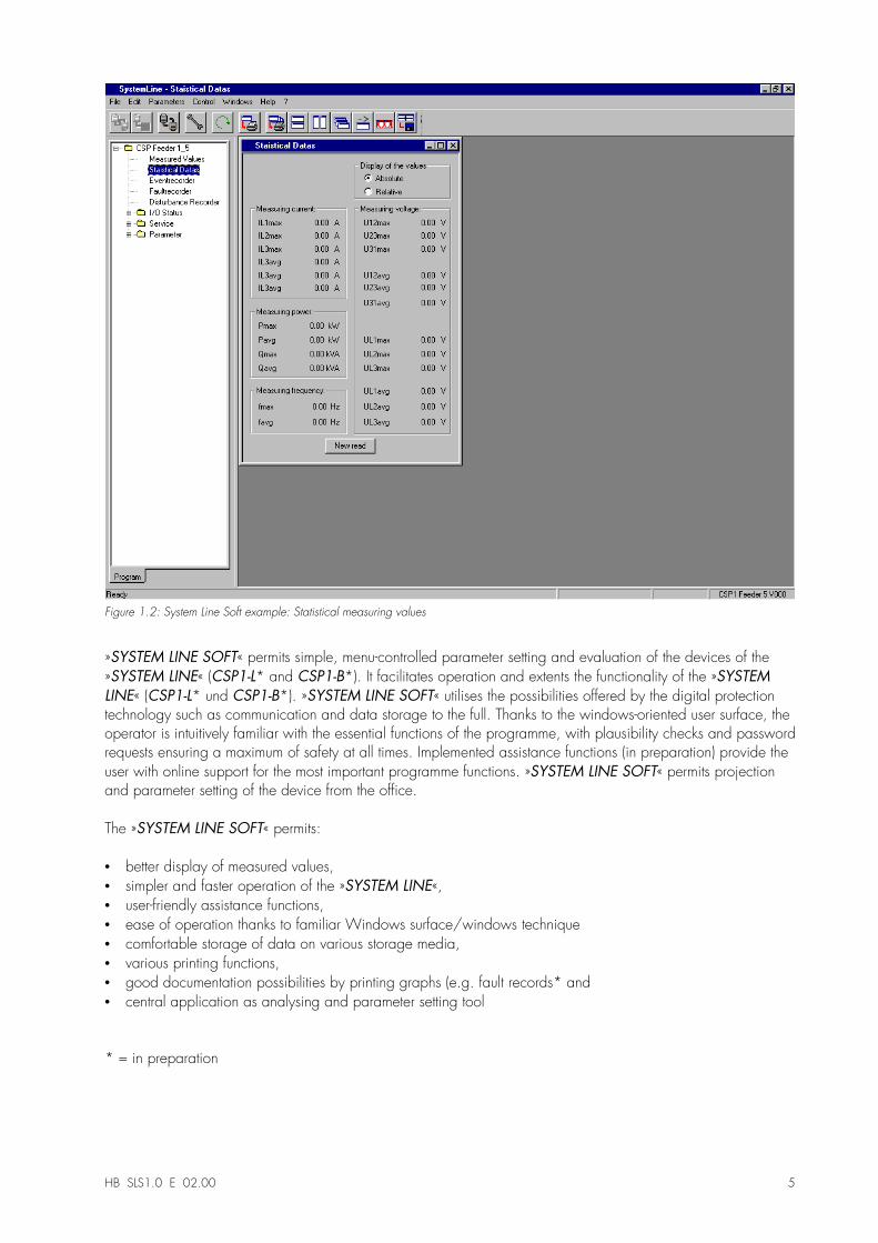
Figure 1.2: System Line Soft example: Statistical measuring values
»SYSTEM LINE SOFT« permits simple, menu-controlled parameter setting and evaluation of the devices of the»SYSTEM LINE« (CSP1-L* and CSP1-B*). It facilitates operation and extents the functionality of the »SYSTEMLINE« (CSP1-L* und CSP1-B*). »SYSTEM LINE SOFT« utilises the possibilities offered by the digital protectiontechnology such as communication and data storage to the full. Thanks to the windows-oriented user surface, theoperator is intuitively familiar with the essential functions of the programme, with plausibility checks and passwordrequests ensuring a maximum of safety at all times. Implemented assistance functions (in preparation) provide theuser with online support for the most important programme functions. »SYSTEM LINE SOFT« permits projectionand parameter setting of the device from the office.
The »SYSTEM LINE SOFT« permits:
•� better display of measured values,•� simpler and faster operation of the »SYSTEM LINE«,•� user-friendly assistance functions,•� ease of operation thanks to familiar Windows surface/windows technique•� comfortable storage of data on various storage media,•� various printing functions,•� good documentation possibilities by printing graphs (e.g. fault records* and•� central application as analysing and parameter setting tool
* = in preparation
6 HB SLS1.0 E 02.00
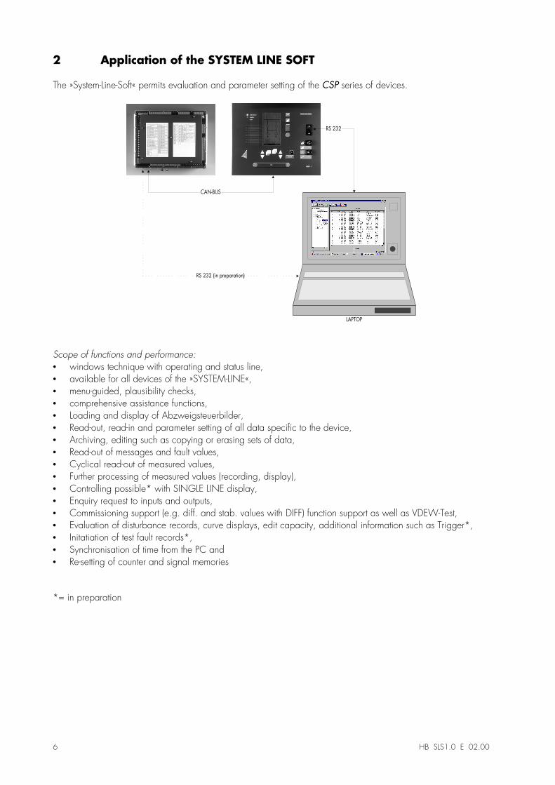
2 Application of the SYSTEM LINE SOFT
The »System-Line-Soft« permits evaluation and parameter setting of the CSP series of devices.
LAPTOP
RS 232
CAN-BUS
RS 232 (in preparation)
Scope of functions and performance:•� windows technique with operating and status line,•� available for all devices of the »SYSTEM-LINE«,•� menu-guided, plausibility checks,•� comprehensive assistance functions,•� Loading and display of Abzweigsteuerbilder,•� Read-out, read-in and parameter setting of all data specific to the device,•� Archiving, editing such as copying or erasing sets of data,•� Read-out of messages and fault values,•� Cyclical read-out of measured values,•� Further processing of measured values (recording, display),•� Controlling possible* with SINGLE LINE display,•� Enquiry request to inputs and outputs,•� Commissioning support (e.g. diff. and stab. values with DIFF) function support as well as VDEW-Test,•� Evaluation of disturbance records, curve displays, edit capacity, additional information such as Trigger*,•� Initatiation of test fault records*,•� Synchronisation of time from the PC and•� Re-setting of counter and signal memories
*= in preparation
HB SLS1.0 E 02.00 7
3 Installation
3.1 Hard- and software conditions
The »SYSTEM LINE SOFT« will run any IBM-compatible PC with operating systems Windows 95/98 or Win-dows NT. Communication takes place via the RS232 interface or via the internal CAN-BUS. It permits operationby mouse (Windows standard/surface) and is equipped with window image / technology controlled by theuser. The »SYSTEM LINE SOFT« is easy to install and is available in various languages (in preparation).
3.2 Installation of the SYSTEM LINE SOFT
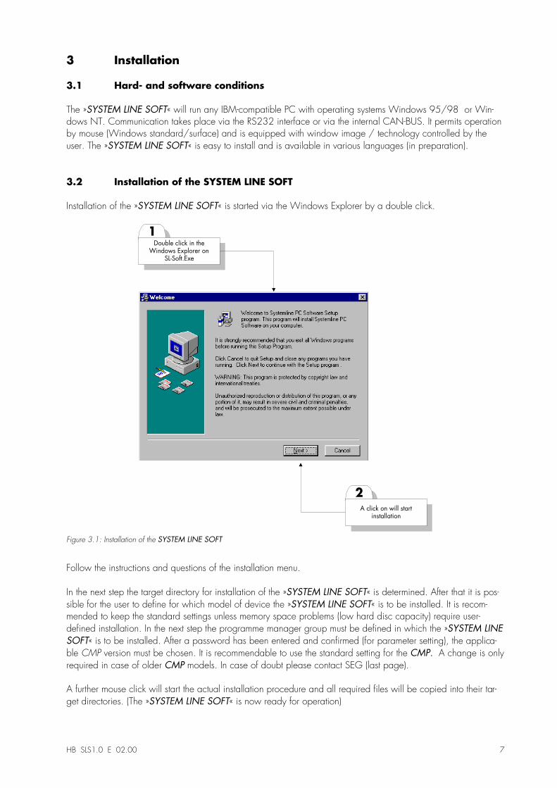
Installation of the »SYSTEM LINE SOFT« is started via the Windows Explorer by a double click.
2
1
A click on will startinstallation
Double click in theWindows Explorer on
SL-Soft.Exe
Figure 3.1: Installation of the SYSTEM LINE SOFT
Follow the instructions and questions of the installation menu.
In the next step the target directory for installation of the »SYSTEM LINE SOFT« is determined. After that it is pos-sible for the user to define for which model of device the »SYSTEM LINE SOFT« is to be installed. It is recom-mended to keep the standard settings unless memory space problems (low hard disc capacity) require user-defined installation. In the next step the programme manager group must be defined in which the »SYSTEM LINESOFT« is to be installed. After a password has been entered and confirmed (for parameter setting), the applica-ble CMP version must be chosen. It is recommendable to use the standard setting for the CMP. A change is onlyrequired in case of older CMP models. In case of doubt please contact SEG (last page).
A further mouse click will start the actual installation procedure and all required files will be copied into their tar-get directories. (The »SYSTEM LINE SOFT« is now ready for operation)
8 HB SLS1.0 E 02.00
4 De-installation
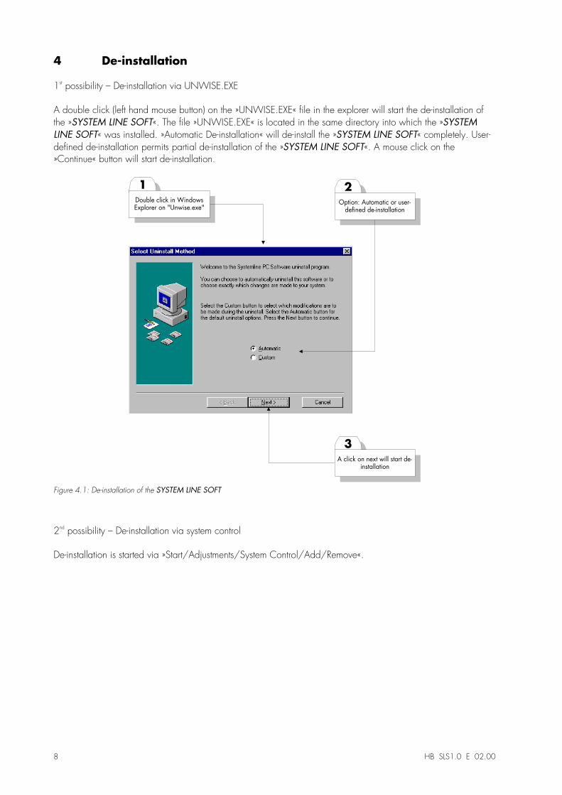
1st possibility � De-installation via UNWISE.EXE
A double click (left hand mouse button) on the »UNWISE.EXE« file in the explorer will start the de-installation ofthe »SYSTEM LINE SOFT«. The file »UNWISE.EXE« is located in the same directory into which the »SYSTEMLINE SOFT« was installed. »Automatic De-installation« will de-install the »SYSTEM LINE SOFT« completely. User-defined de-installation permits partial de-installation of the »SYSTEM LINE SOFT«. A mouse click on the»Continue« button will start de-installation.
3
1
A click on next will start de-installation
Double click in WindowsExplorer on "Unwise.exe"
2
Option: Automatic or user-defined de-installation
Figure 4.1: De-installation of the SYSTEM LINE SOFT
2nd possibility � De-installation via system control
De-installation is started via »Start/Adjustments/System Control/Add/Remove«.
HB SLS1.0 E 02.00 9
5 Required configurations
Communication between the PC/Laptop and the CSP1 can alternatively be realised via zero-modem cable (referto 5.1.1) or via CAN BUS cable (refer to 5.1.2).
5.1.1 Starting the programme � communication via RS232
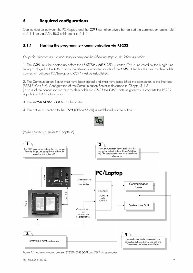
For perfect functioning it is necessary to carry out the following steps in the following order:
1. The CSP1 must be booted up before the »SYSTEM LINE SOFT« is started. This is indicated by the Single Linebeing displayed in the CMP1 or by the relevant illuminated diode of the CSP1. After that the zero-modem cableconnection between PC/Laptop and CSP1 must be established.
2. The Communication Server must have been started and must have established the connection to the interface(RS232/Can-Bus). Configuration of the Communication Server is described in Chapter 5.1.5.(In case of the connection via zero-modem cable via CMP1 the CMP1 acts as gateway. It converts the RS232signals into CAN-BUS signals).
3. The »SYSTEM LINE SOFT« can be started.
4. The active connection to the CSP1 (Online Mode) is established via the button
(make connection) (refer to Chapter 6).
3
21
PC/Laptop
The CSP1 must be booted up. This can be seenfrom the Single Line being shown or from the
respective LED of the CSP1.
The Communication Server establishes theconnection to the interface (COM-Port/Can-Bus). The zero-modem cable must have been
plugged in.
SYSTEM LINE SOFT can be started
CommunicationServer
CAN-BUS
CSP1
CM
P1
System Line Soft
Schnittstelle
COM-Portoder
CAN-Bus
Communicationvia
zero-modem
4
Via the button "Make connection" theconnection between System Line Soft and
Communication Server is established
Communicationvia
zero-modem(in preparation)
Figure 5.1: Active connection between SYSTEM LINE SOFT and CSP1 via zero-modem
10 HB SLS1.0 E 02.00
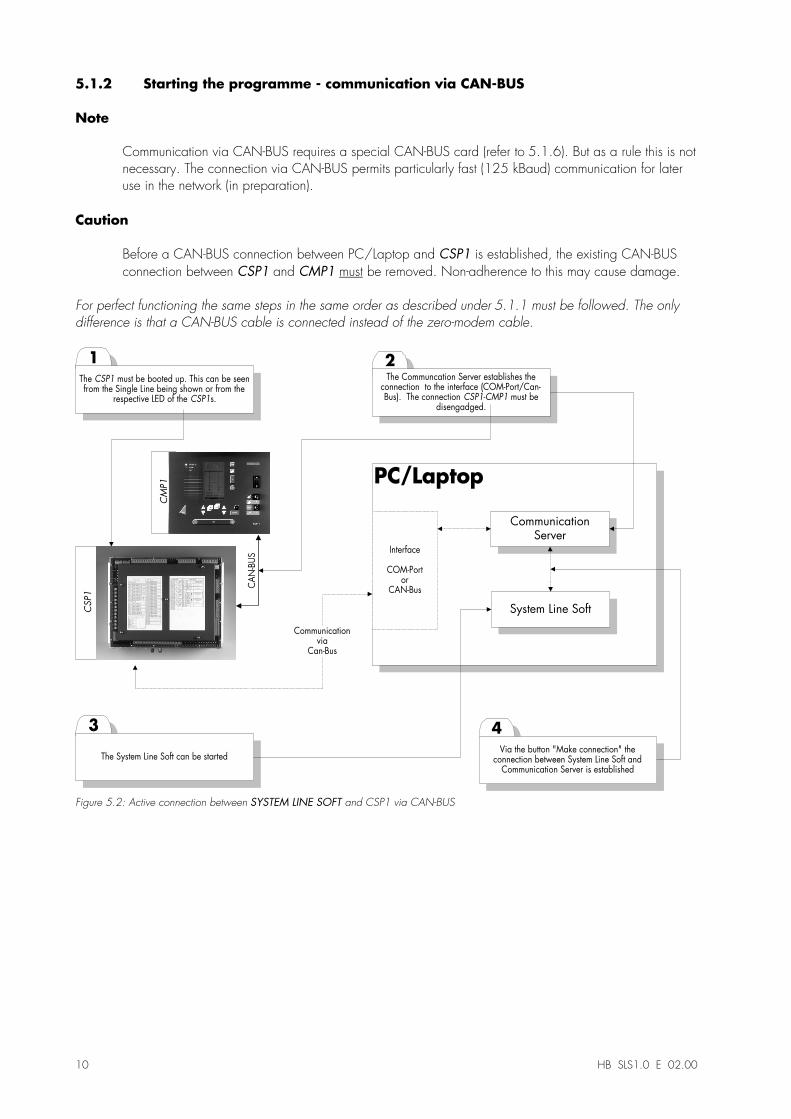
5.1.2 Starting the programme - communication via CAN-BUS
Note
Communication via CAN-BUS requires a special CAN-BUS card (refer to 5.1.6). But as a rule this is notnecessary. The connection via CAN-BUS permits particularly fast (125 kBaud) communication for lateruse in the network (in preparation).
Caution
Before a CAN-BUS connection between PC/Laptop and CSP1 is established, the existing CAN-BUSconnection between CSP1 and CMP1 must be removed. Non-adherence to this may cause damage.
For perfect functioning the same steps in the same order as described under 5.1.1 must be followed. The onlydifference is that a CAN-BUS cable is connected instead of the zero-modem cable.
3
21
PC/Laptop
The CSP1 must be booted up. This can be seenfrom the Single Line being shown or from the
respective LED of the CSP1s.
The Communcation Server establishes theconnection to the interface (COM-Port/Can-Bus). The connection CSP1-CMP1 must be
disengadged.
The System Line Soft can be started
CommunicationServer
CAN-BUS
CSP1
CM
P1
System Line Soft
Interface
COM-Portor
CAN-Bus
4
Via the button "Make connection" theconnection between System Line Soft and
Communication Server is established
Communicationvia
Can-Bus
Figure 5.2: Active connection between SYSTEM LINE SOFT and CSP1 via CAN-BUS
HB SLS1.0 E 02.00 11
5.1.3 Terminating the programme - communication via RS232
In order to avoid complications when terminating the programme, the following steps must be carried out in thisfixed order.
1.� The active connection to the CSP1 (Online mode) is terminated via the button
(break connection) (refer to chapter on layout of surface)
2. The »SYSTEM LINE SOFT« is closed�
3. In the Communication Server the connection is interrupted and then terminated (The CMP1 returns from thegetaway mode to normal operating mode.).
4. The zero-modem cable connection (RS232) must be interrupted.
5.1.4 Terminating the programme - communication via CAN-BUS
In order to avoid complications when terminating the programme, the following steps must be carried out in thisfixed order.
1. The active connection to the CSP1 (Online mode) is terminated via the button
(break connection) (refer to chapter on layout of surface)
2. The »SYSTEM LINE SOFT« is closed.
3. In the Communication Server the connection is interrupted and then terminated (The CMP1 returns from thegetaway mode to normal operating mode.).
4. Remove CAN-BUS cable connection between CSP1 and PC/Laptop. (This cable can also be removedearlier.)
5. It is only now that the CAN-Bus connection between CSP1 and CMP1 may be re-established.
12 HB SLS1.0 E 02.00
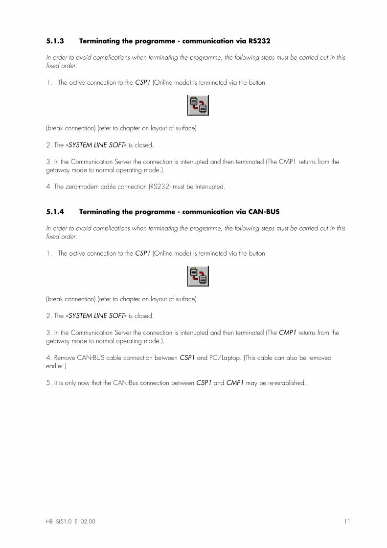
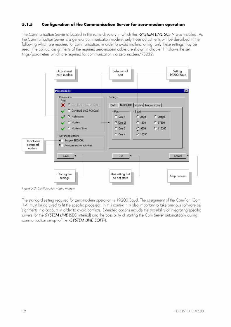
5.1.5 Configuration of the Communication Server for zero-modem operation
The Communication Server is located in the same directory in which the »SYSTEM LINE SOFT« was installed. Asthe Communication Server is a general communication module, only those adjustments will be described in thefollowing which are required for communication. In order to avoid malfunctioning, only these settings may beused. The contact assignments of the required zero-modem cable are shown in chapter 11 shows the set-tings/parameters which are required for communication via zero modem/RS232.
Adjustmentzero modem
Storing thesettings
Use setting butdo not store
Stop process
Selection ofport
Setting 19200 Baud
De-activateextendedoptions
Figure 5.3: Configuration � zero modem
The standard setting required for zero-modem operation is 19200 Baud. The assignment of the Com-Port (Com1-4) must be adjusted to fit the specific processor. In this context it is also important to take previous software as-signments into account in order to avoid conflicts. Extended options include the possibility of integrating specificdrivers for the SYSTEM LINE (SEG internal) and the possibility of starting the Com Server automatically duringcommunication set-up (of the »SYSTEM LINE SOFT«).
HB SLS1.0 E 02.00 13
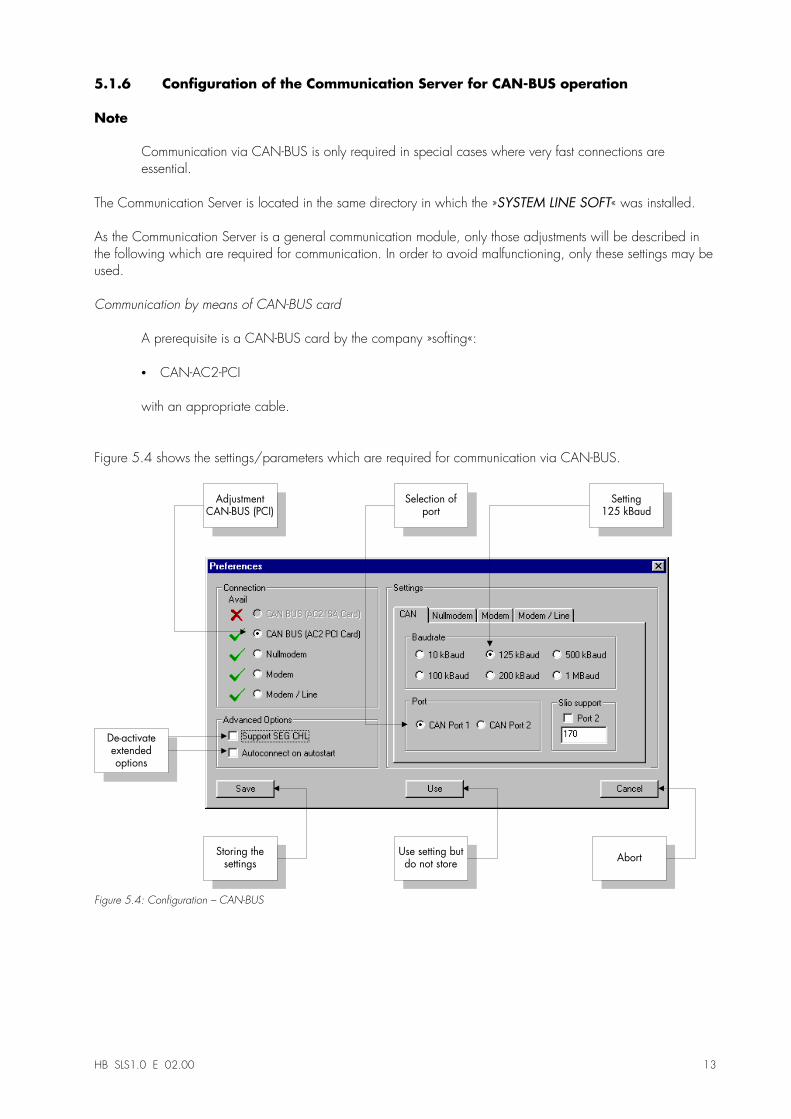
5.1.6 Configuration of the Communication Server for CAN-BUS operation
Note
Communication via CAN-BUS is only required in special cases where very fast connections areessential.
The Communication Server is located in the same directory in which the »SYSTEM LINE SOFT« was installed.
As the Communication Server is a general communication module, only those adjustments will be described inthe following which are required for communication. In order to avoid malfunctioning, only these settings may beused.
Communication by means of CAN-BUS card
A prerequisite is a CAN-BUS card by the company »softing«:
•� CAN-AC2-PCI
with an appropriate cable.
Figure 5.4 shows the settings/parameters which are required for communication via CAN-BUS.
AdjustmentCAN-BUS (PCI)
Storing thesettings
Use setting butdo not store
Abort
Selection ofport
Setting125 kBaud
De-activateextendedoptions
Figure 5.4: Configuration � CAN-BUS
14 HB SLS1.0 E 02.00
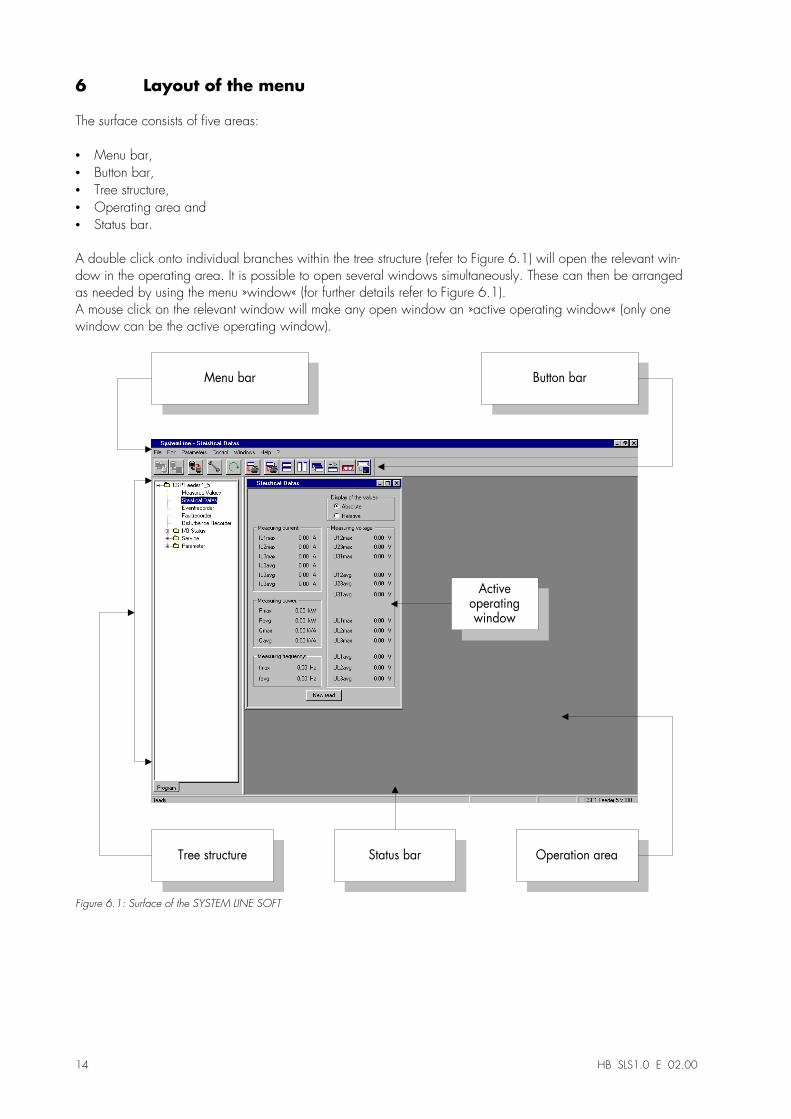
6 Layout of the menu
The surface consists of five areas:
•� Menu bar,•� Button bar,•� Tree structure,•� Operating area and•� Status bar.
A double click onto individual branches within the tree structure (refer to Figure 6.1) will open the relevant win-dow in the operating area. It is possible to open several windows simultaneously. These can then be arrangedas needed by using the menu »window« (for further details refer to Figure 6.1).A mouse click on the relevant window will make any open window an »active operating window« (only onewindow can be the active operating window).
Menu bar Button bar
Tree structure Operation area
Activeoperatingwindow
Status bar
Figure 6.1: Surface of the SYSTEM LINE SOFT
HB SLS1.0 E 02.00 15
Note:
The »SYSTEM LINE SOFT« has two operating modes:
•� Parameter setting and•� Evaluation/data reading
The operating mode »Parameter setting« is only accessible via a previously fixed password.
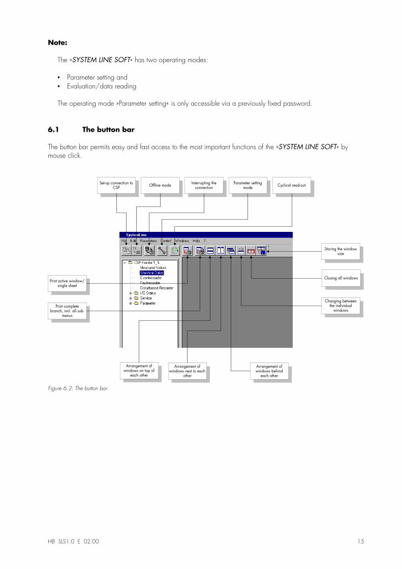
6.1 The button bar
The button bar permits easy and fast access to the most important functions of the »SYSTEM LINE SOFT« bymouse click.
Set-up connection toCSP
Offline modeInterrupting the
connectionParameter setting
modeCyclical read-out
Arrangement ofwindows next to each
other
Arrangement ofwindows behind
each other
Changing betweenthe individual
windows
Closing all windows
Storing the windowsize
Print active window/single sheet
Print completebranch, incl. all sub-
menus
Arrangement ofwindows on top of
each other
Figure 6.2: The button bar
16 HB SLS1.0 E 02.00
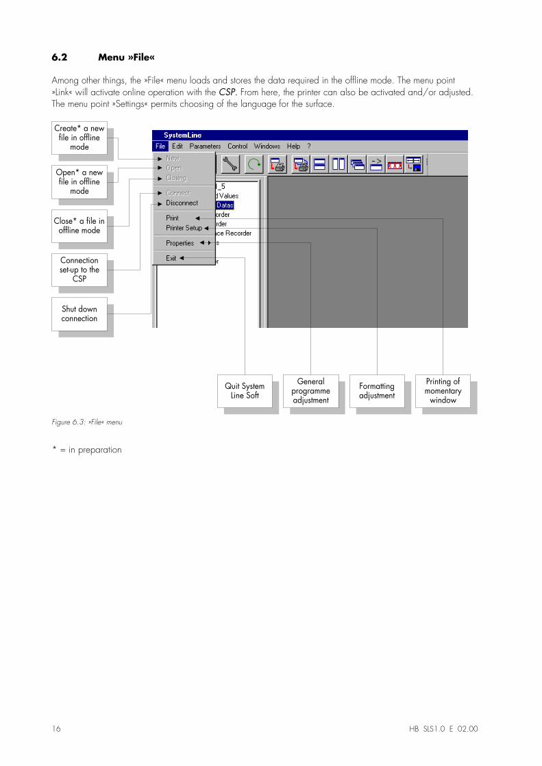
6.2 Menu »File«
Among other things, the »File« menu loads and stores the data required in the offline mode. The menu point»Link« will activate online operation with the CSP. From here, the printer can also be activated and/or adjusted.The menu point »Settings« permits choosing of the language for the surface.
Shut downconnection
Connectionset-up to the
CSP
Close* a file inoffline mode
Open* a newfile in offline
mode
Create* a newfile in offline
mode
Quit SystemLine Soft
Generalprogrammeadjustment
Formattingadjustment
Printing ofmomentary
window
Figure 6.3: »File« menu
* = in preparation
HB SLS1.0 E 02.00 17
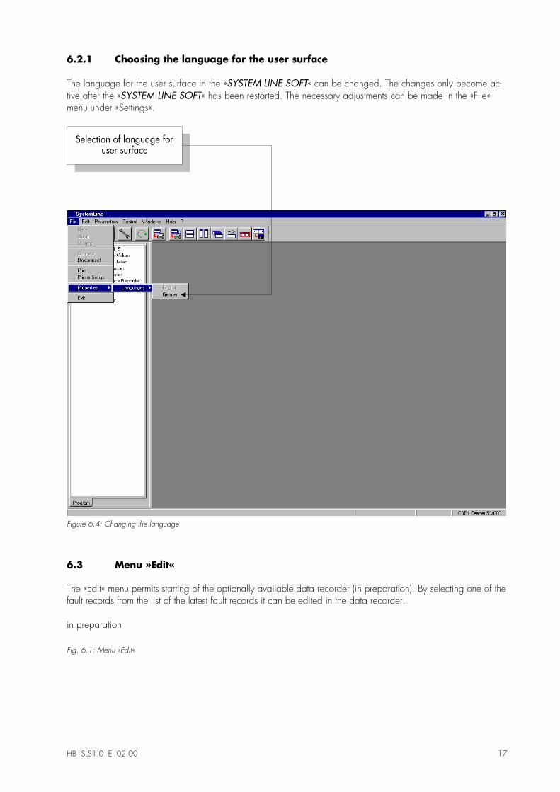
6.2.1 Choosing the language for the user surface
The language for the user surface in the »SYSTEM LINE SOFT« can be changed. The changes only become ac-tive after the »SYSTEM LINE SOFT« has been restarted. The necessary adjustments can be made in the »File«menu under »Settings«.
Selection of language foruser surface
Figure 6.4: Changing the language
6.3 Menu »Edit«
The »Edit« menu permits starting of the optionally available data recorder (in preparation). By selecting one of thefault records from the list of the latest fault records it can be edited in the data recorder.
in preparation
Fig. 6.1: Menu »Edit«
18 HB SLS1.0 E 02.00
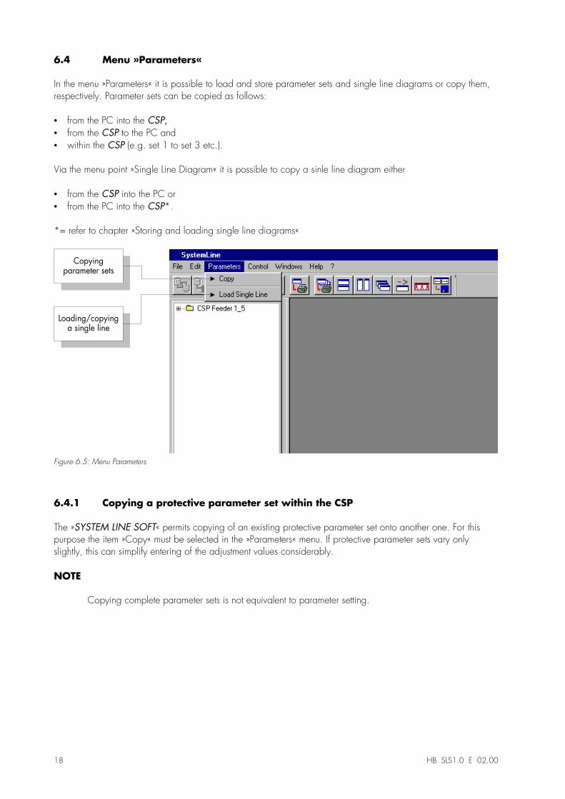
6.4 Menu »Parameters«
In the menu »Parameters« it is possible to load and store parameter sets and single line diagrams or copy them,respectively. Parameter sets can be copied as follows:
•� from the PC into the CSP,•� from the CSP to the PC and•� within the CSP (e.g. set 1 to set 3 etc.).
Via the menu point »Single Line Diagram« it is possible to copy a sinle line diagram either
•� from the CSP into the PC or•� from the PC into the CSP*.
*= refer to chapter »Storing and loading single line diagrams«
Copyingparameter sets
Loading/copyinga single line
Figure 6.5: Menu Parameters
6.4.1 Copying a protective parameter set within the CSP
The »SYSTEM LINE SOFT« permits copying of an existing protective parameter set onto another one. For thispurpose the item »Copy« must be selected in the »Parameters« menu. If protective parameter sets vary onlyslightly, this can simplify entering of the adjustment values considerably.
NOTE
Copying complete parameter sets is not equivalent to parameter setting.
HB SLS1.0 E 02.00 19
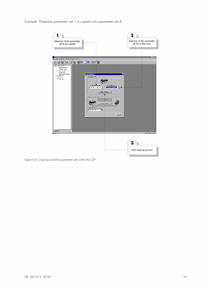
Example: Protective parameter set 1 is copied onto parameter set 4.
3
1
Start copying process
Selection of the parameterset to be copied
2
Selection of the parameterset be written over
Figure 6.6: Copying protective parameter sets within the CSP
20 HB SLS1.0 E 02.00
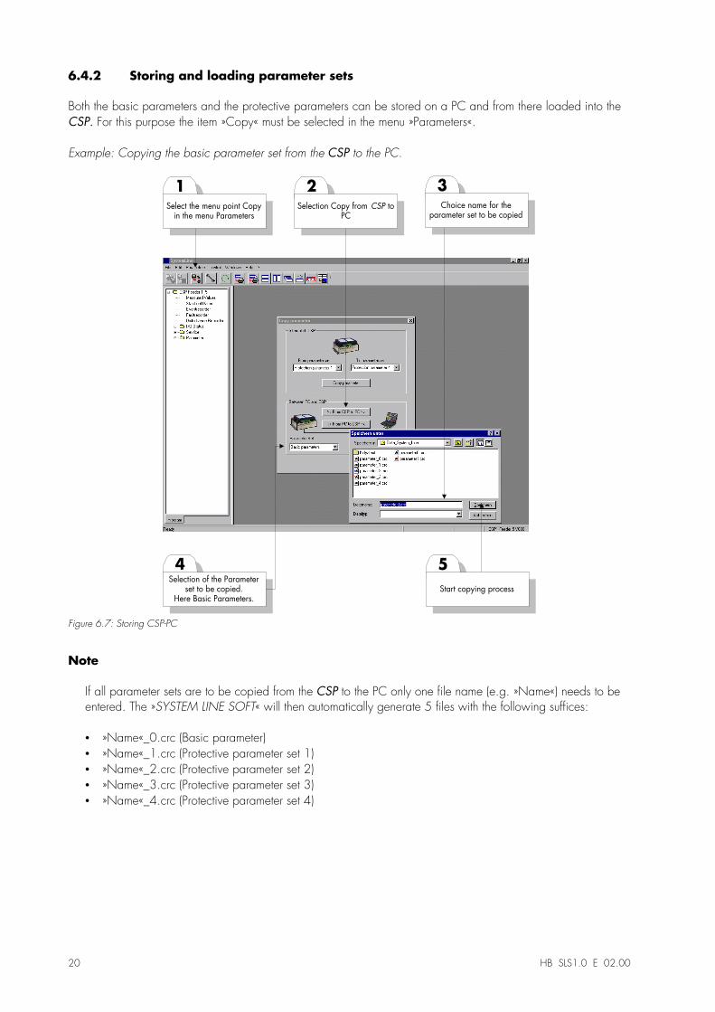
6.4.2 Storing and loading parameter sets
Both the basic parameters and the protective parameters can be stored on a PC and from there loaded into theCSP. For this purpose the item »Copy« must be selected in the menu »Parameters«.
Example: Copying the basic parameter set from the CSP to the PC.
5
1
Start copying process
Select the menu point Copyin the menu Parameters
3
Choice name for theparameter set to be copied
4Selection of the Parameter
set to be copied.Here Basic Parameters.
2
Selection Copy from CSP toPC
Figure 6.7: Storing CSP-PC
Note
If all parameter sets are to be copied from the CSP to the PC only one file name (e.g. »Name«) needs to beentered. The »SYSTEM LINE SOFT« will then automatically generate 5 files with the following suffices:
•� »Name«_0.crc (Basic parameter)•� »Name«_1.crc (Protective parameter set 1)•� »Name«_2.crc (Protective parameter set 2)•� »Name«_3.crc (Protective parameter set 3)•� »Name«_4.crc (Protective parameter set 4)
HB SLS1.0 E 02.00 21
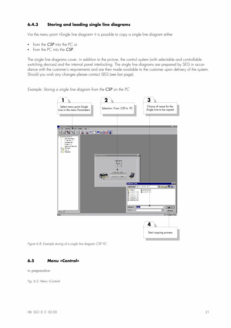
6.4.3 Storing and loading single line diagrams
Via the menu point »Single line diagram« it is possible to copy a single line diagram either
•� from the CSP into the PC or•� from the PC into the CSP.
The single line diagrams cover, in addition to the picture, the control system (with selectable and controllableswitching devices) and the internal panel interlocking. The single line diagrams are prepared by SEG in accor-dance with the customer's requirements and are then made available to the customer upon delivery of the system.Should you wish any changes please contact SEG (see last page).
Example: Storing a single line diagram from the CSP on the PC
4
1
Start copying process
Select menu point SingleLine in the menu Parameters
3
Choice of name for theSingle Line to be copied
2
Selection: From CSP to PC
Figure 6.8: Example storing of a single line diagram CSP- PC
6.5 Menu »Control«
in preparation
Fig. 6.2: Menu »Control«
22 HB SLS1.0 E 02.00
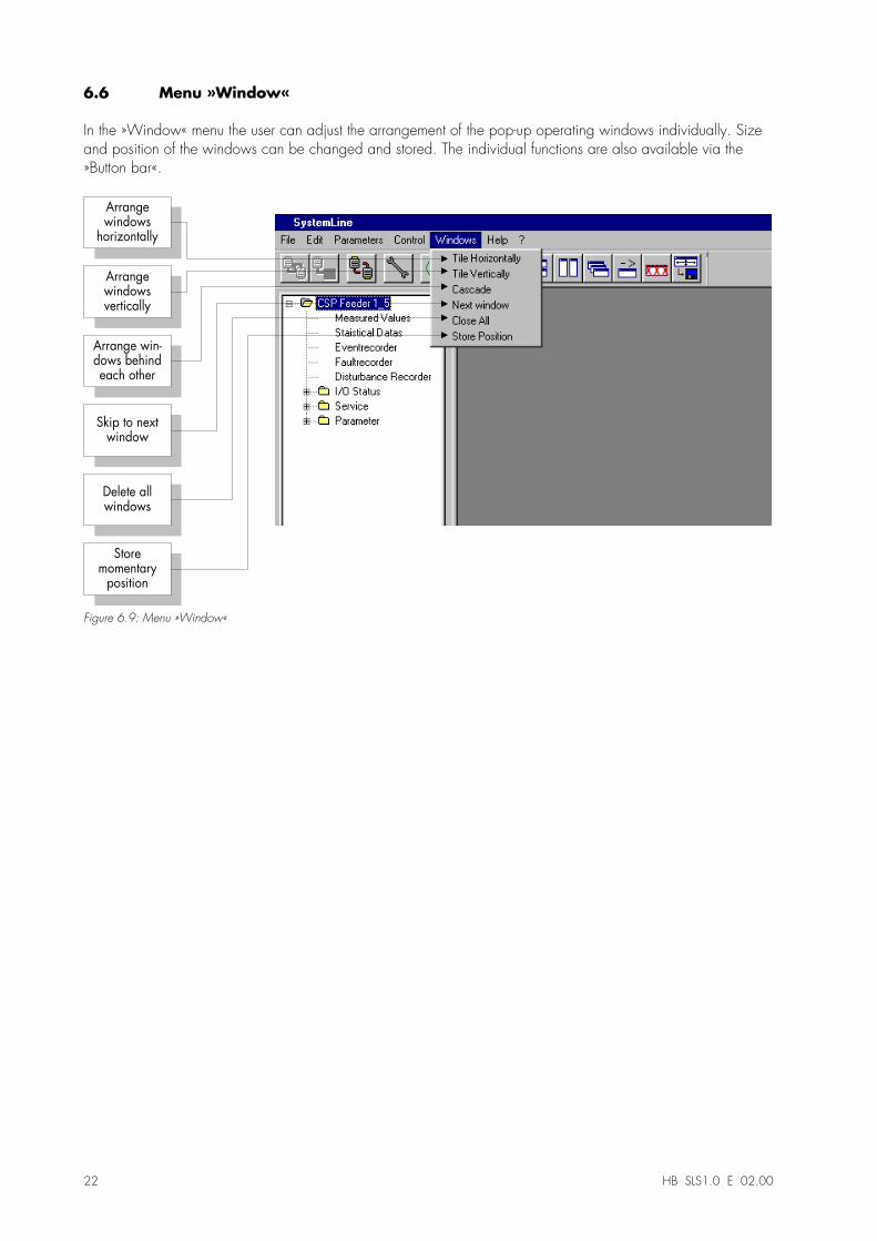
6.6 Menu »Window«
In the »Window« menu the user can adjust the arrangement of the pop-up operating windows individually. Sizeand position of the windows can be changed and stored. The individual functions are also available via the»Button bar«.
Delete allwindows
Skip to nextwindow
Arrange win-dows behindeach other
Arrangewindowsvertically
Arrangewindows
horizontally
Storemomentary
position
Figure 6.9: Menu »Window«
HB SLS1.0 E 02.00 23
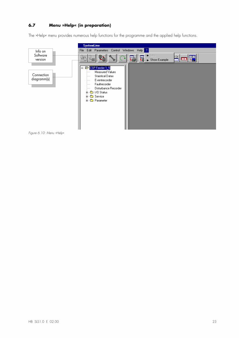
6.7 Menu »Help« (in preparation)
The »Help« menu provides numerous help functions for the programme and the applied help functions.
Connectiondiagramm(s)
Info onSoftwareversion
Figure 6.10: Menu »Help«
24 HB SLS1.0 E 02.00
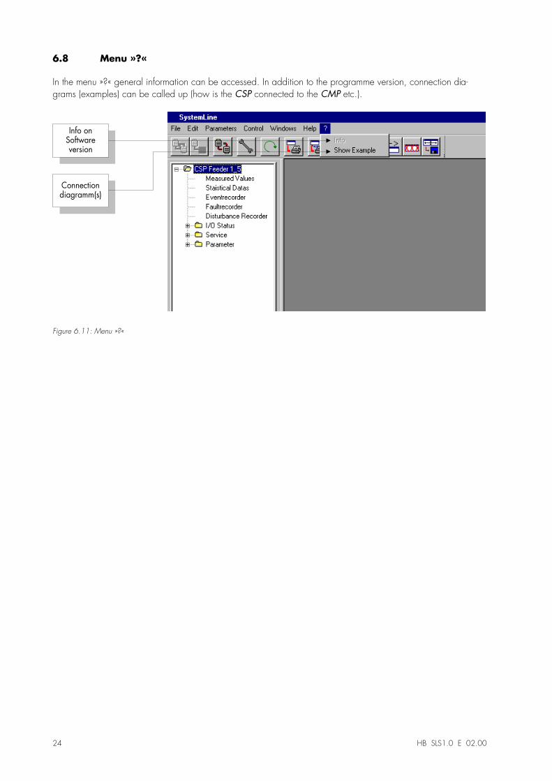
6.8 Menu »?«
In the menu »?« general information can be accessed. In addition to the programme version, connection dia-grams (examples) can be called up (how is the CSP connected to the CMP etc.).
Connectiondiagramm(s)
Info onSoftwareversion
Figure 6.11: Menu »?«
HB SLS1.0 E 02.00 25
7 The tree structure of the SYSTEM LINE SOFT
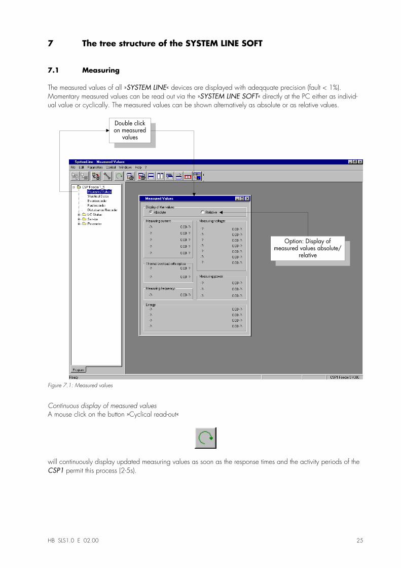
7.1 Measuring
The measured values of all »SYSTEM LINE« devices are displayed with adeqquate precision (fault < 1%).Momentary measured values can be read out via the »SYSTEM LINE SOFT« directly at the PC either as individ-ual value or cyclically. The measured values can be shown alternatively as absolute or as relative values.
Double clickon measured
values
Option: Display ofmeasured values absolute/
relative
Figure 7.1: Measured values
Continuous display of measured valuesA mouse click on the button »Cyclical read-out«
will continuously display updated measuring values as soon as the response times and the activity periods of theCSP1 permit this process (2-5s).
26 HB SLS1.0 E 02.00
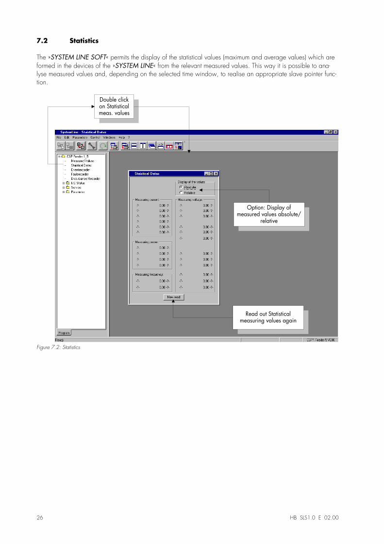
7.2 Statistics
The »SYSTEM LINE SOFT« permits the display of the statistical values (maximum and average values) which areformed in the devices of the »SYSTEM LINE« from the relevant measured values. This way it is possible to ana-lyse measured values and, depending on the selected time window, to realise an appropriate slave pointer func-tion.
Double clickon Statisticalmeas. values
Option: Display ofmeasured values absolute/
relative
Read out Statisticalmeasuring values again
Figure 7.2: Statistics
HB SLS1.0 E 02.00 27
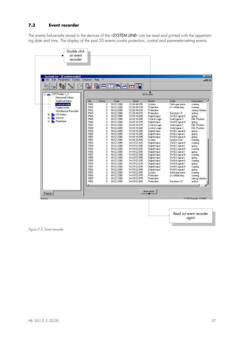
7.3 Event recorder
The events failure-safe stored in the devices of the »SYSTEM LINE« can be read and printed with the appertain-ing date and time. The display of the past 50 events covers protection, control and parameter-setting events.
Double clickon eventrecorder
Read out event recorderagain
Figure 7.3: Event recorder

28 HB SLS1.0 E 02.00
7.4 Fault recorder
The fault recorder stores the measured values which have lead to tripping. The latest 5 faults are stored failure-safe.
Read out fault recorderagain
1
Double click on faultrecorder
2
Double click on a faultevent
Figure 7.4: Fault recorder
HB SLS1.0 E 02.00 29
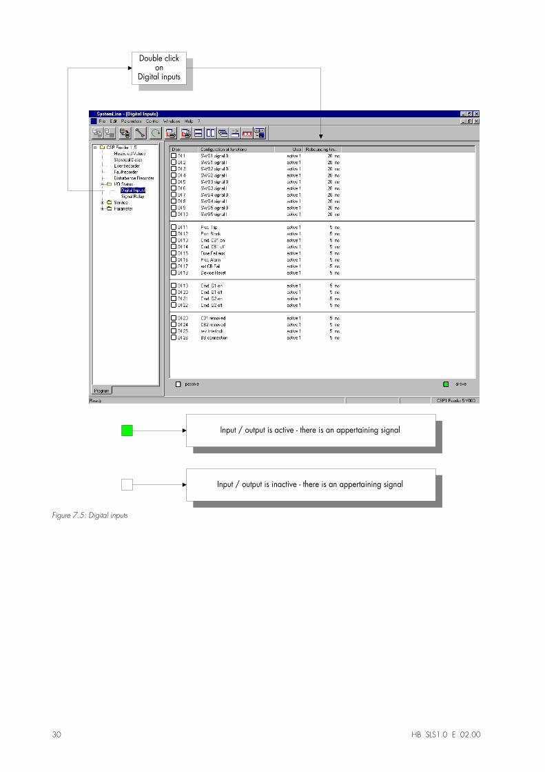
7.5 I/O-Status
By way of the I/O-Status it is possible to display the momentary status of all digital inputs and outputs. For exam-ple, the wiring can easily be checked during installation or commissioning work. The assignment of the digitalinputs is shown with the configured function.
7.5.1 Digital inputs
Cyclical readoutA mouse click on the button »Cyclical readout«
will continuously show the momentary status of the digital inputs as soon as the response times and the activityperiods of the CSP1 permit this (2-5s).
30 HB SLS1.0 E 02.00
Double clickon
Digital inputs
Input / output is active - there is an appertaining signal
Input / output is inactive - there is an appertaining signal
Figure 7.5: Digital inputs
HB SLS1.0 E 02.00 31
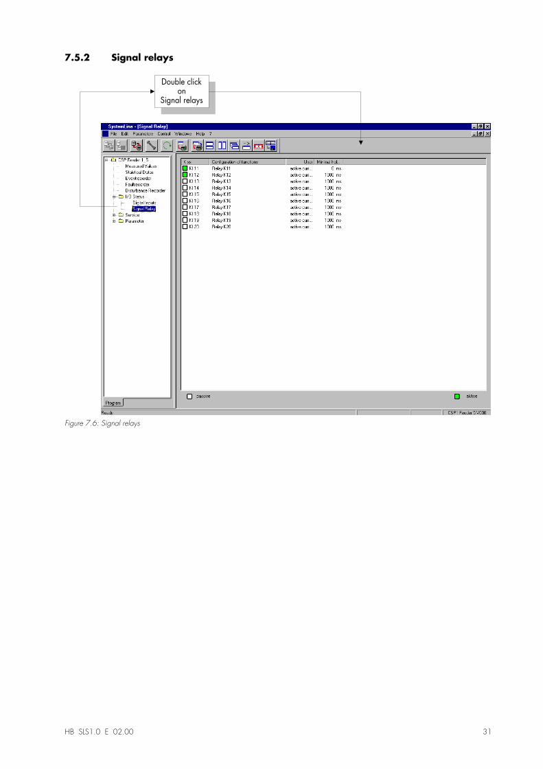
7.5.2 Signal relays
Double clickon
Signal relays
Figure 7.6: Signal relays
32 HB SLS1.0 E 02.00
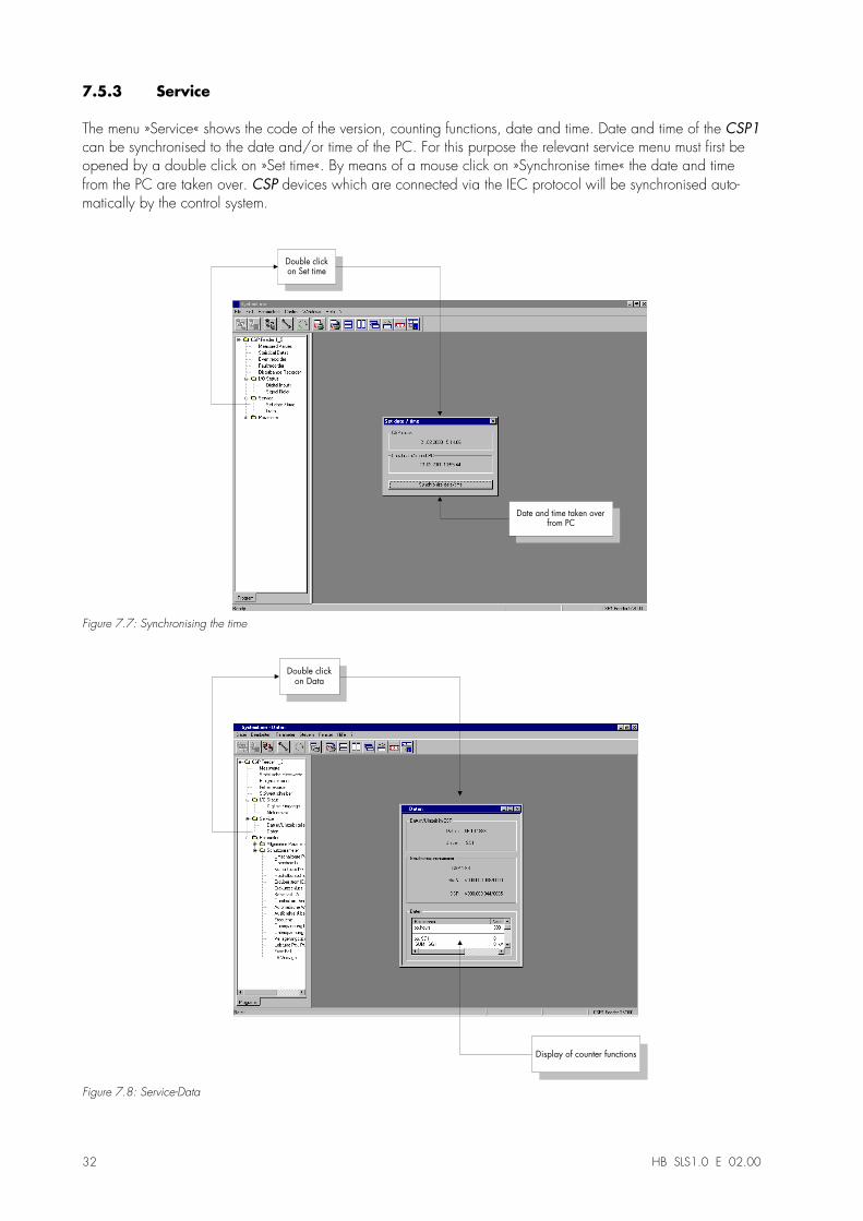
7.5.3 Service
The menu »Service« shows the code of the version, counting functions, date and time. Date and time of the CSP1can be synchronised to the date and/or time of the PC. For this purpose the relevant service menu must first beopened by a double click on »Set time«. By means of a mouse click on »Synchronise time« the date and timefrom the PC are taken over. CSP devices which are connected via the IEC protocol will be synchronised auto-matically by the control system.
Double click
on Set time
Date and time taken over
from PC
Figure 7.7: Synchronising the time
Double clickon Data
Display of counter functions
Figure 7.8: Service-Data

HB SLS1.0 E 02.00 33
7.5.4 Self-test
in preparation
34 HB SLS1.0 E 02.00
8 Parameter setting
The parameters are categorised as basic parameters and protection parameters.
The basic parameters include
•� panel parameters,•� control times,•� digital inputs,•� signal relays,•� LED configuration,•� fault recorder* and•� communication.
* = in preparation
The protection parameters consist of 4 parameter sets and it is possible to switch over between them (see 8.3).The exact parameter setting alternatives can be found in the relevant manuals of the »SYSTEM LINE«. The princi-ple procedure of parameter setting is only illustrated on the basis of a few examples at this point.
Note
•� Changes in the protective parameter sets (1-4) which are made during the parameter setting modeare taken over immediately. It is not necessary to restart the CSP1. After changes in the basic pa-rameter set the CSP1 is automatically restarted in order to take over the performed parameter setting.
Note
•� If no changes are made for 10 minutes in the parameter setting mode all previsouly made changesare cancelled unless the parameter setting mode was left correctly.
HB SLS1.0 E 02.00 35
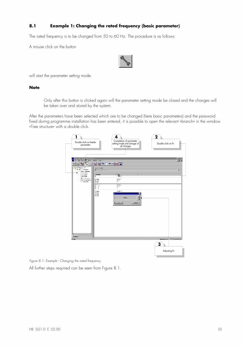
8.1 Example 1: Changing the rated frequency (basic parameter)
The rated frequency is to be changed from 50 to 60 Hz. The procedure is as follows:
A mouse click on the button
will start the parameter setting mode.
Note
Only after this button is clicked again will the parameter setting mode be closed and the changes willbe taken over and stored by the system.
After the parameters have been selected which are to be changed (here basic parameters) and the passwordfixed during programme installation has been entered, it is possible to open the relevant »branch« in the window»Tree structure« with a double click.
3
1
Adjusting fn
Double click on feederparameter
2
Double click on fn
4Completion of parameter
setting mode and storage ofall changes
Figure 8.1: Example - Changing the rated frequency
All further steps required can be seen from Figure 8.1.
36 HB SLS1.0 E 02.00
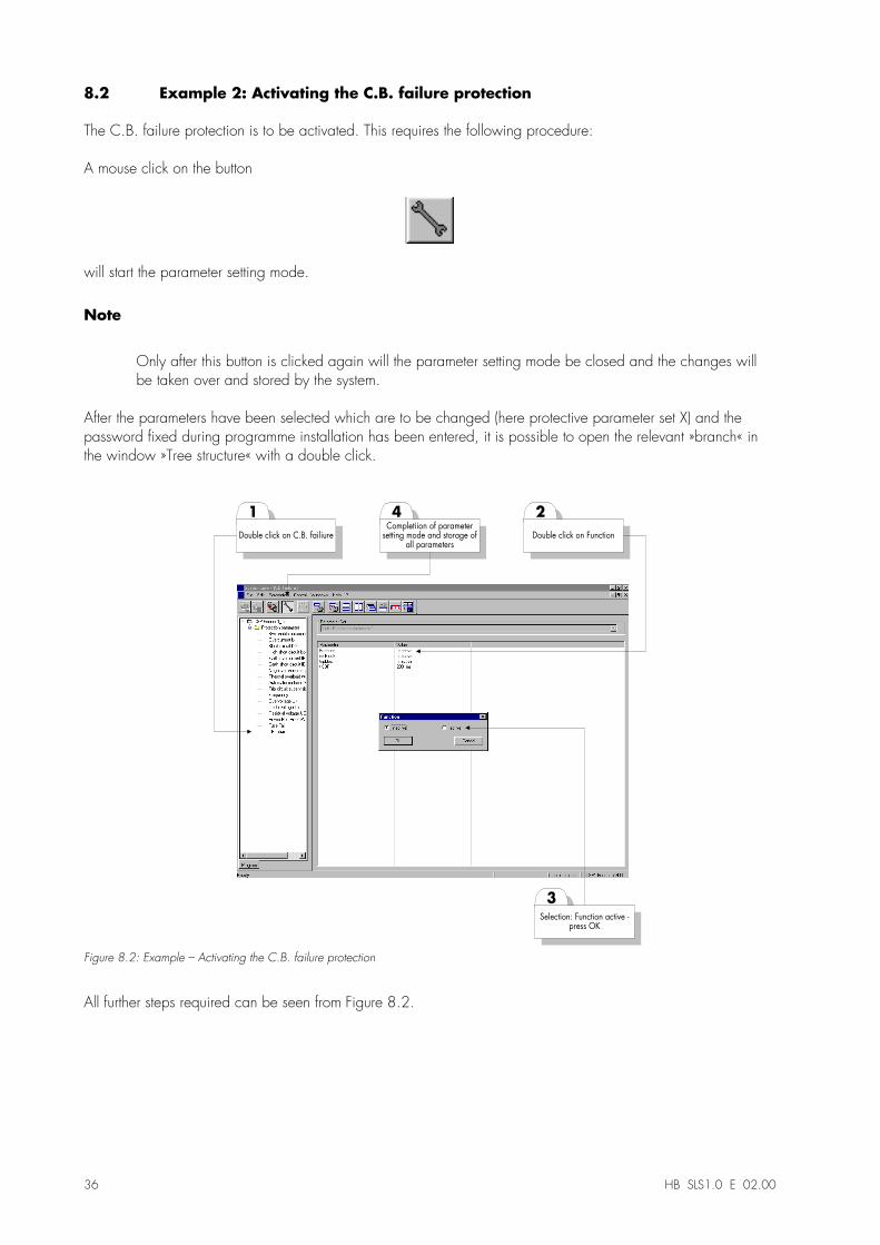
8.2 Example 2: Activating the C.B. failure protection
The C.B. failure protection is to be activated. This requires the following procedure:
A mouse click on the button
will start the parameter setting mode.
Note
Only after this button is clicked again will the parameter setting mode be closed and the changes willbe taken over and stored by the system.
After the parameters have been selected which are to be changed (here protective parameter set X) and thepassword fixed during programme installation has been entered, it is possible to open the relevant »branch« inthe window »Tree structure« with a double click.
3
1
Selection: Function active -press OK
Double click on C.B. failiure
2
Double click on Function
4Completiion of parameter
setting mode and storage ofall parameters
Figure 8.2: Example � Activating the C.B. failure protection
All further steps required can be seen from Figure 8.2.
HB SLS1.0 E 02.00 37
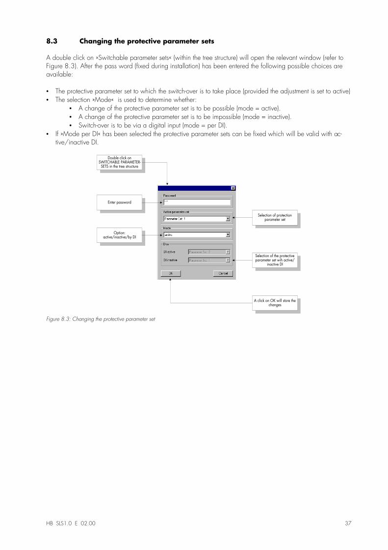
8.3 Changing the protective parameter sets
A double click on »Switchable parameter sets« (within the tree structure) will open the relevant window (refer toFigure 8.3). After the pass word (fixed during installation) has been entered the following possible choices areavailable:
•� The protective parameter set to which the switch-over is to take place (provided the adjustment is set to active)•� The selection »Mode« is used to determine whether:
•� A change of the protective parameter set is to be possible (mode = active).•� A change of the protective parameter set is to be impossible (mode = inactive).•� Switch-over is to be via a digital input (mode = per DI).
•� If »Mode per DI« has been selected the protective parameter sets can be fixed which will be valid with ac-tive/inactive DI.
A click on OK will store thechanges
Double click onSWITCHABLE PARAMETER-
SETS in the tree structure
Enter password
Selection of protectionparameter set
Option:active/inactive/by DI
Selection of the protectiveparameter set wih active/
inactive DI
Figure 8.3: Changing the protective parameter set
38 HB SLS1.0 E 02.00
9 Printing
The »SYSTEM LINE SOFT« permits both printing of a single active window and printing of a complete branch,incl. all sub-menus.
9.1 Preliminary printer settings
In [File > Prelim. printer settings] the formats of the header and footer as well as the standard text can be indi-vidually adjusted. In addition, the user has a description field at his disposal where he can enter remarks, for ex-ample.
9.2 Printing the active window
A click on the button
will print the active window.
9.3 Printing a complete branch inclusive of all submenus
A mouse click on the button
will print the momentary branch of the tree structure with all sub-windows.
10 Data recorder (optional)
10.1 Introduction
The data recorder is a universally applicable tool for the evaluation of fault records, currents and voltages whenfaults occur or at other times determined by the user. The data recorder evaluates the fault records stored in theindividual protection devices.With this programme it is possible to visually display, process, store and print fault records in their chronologicalprogress (as oscillographic curves) with the appertaining events (such as tripping, alarm, etc.). The data recorderoffers the user:
•� Analysis of the fault,•� detection of the faulty consumer,•� the reaction of the grid and•� the switch-off behaviour of the circuit breaker.
This information provides the user with the basis for the analysis of faults and weak points of his electrical equip-ment. On this basis it is possible, for example,
•� to adjust or revise circuit breakers,•� to limit short circuit powers,•� to optimise transformers (capacity / uK),•� to adjust converters (saturation behaviour).
10.2 Hard- and software prerequisites
The »Data recorder« will work on any IBM-compatible PC (as from i486) with the operating systems Windows95/98 or Windows NT4. It permits operation by mouse (Windows standard/surface) and has a user-guidedwindow display / windowing.
10.3 Installation of the data recorder
The installations routine is in preparation
10.4 De-installation of the data recorder
The de-installation routine is in preparation
40 HB SLS1.0 E 02.00
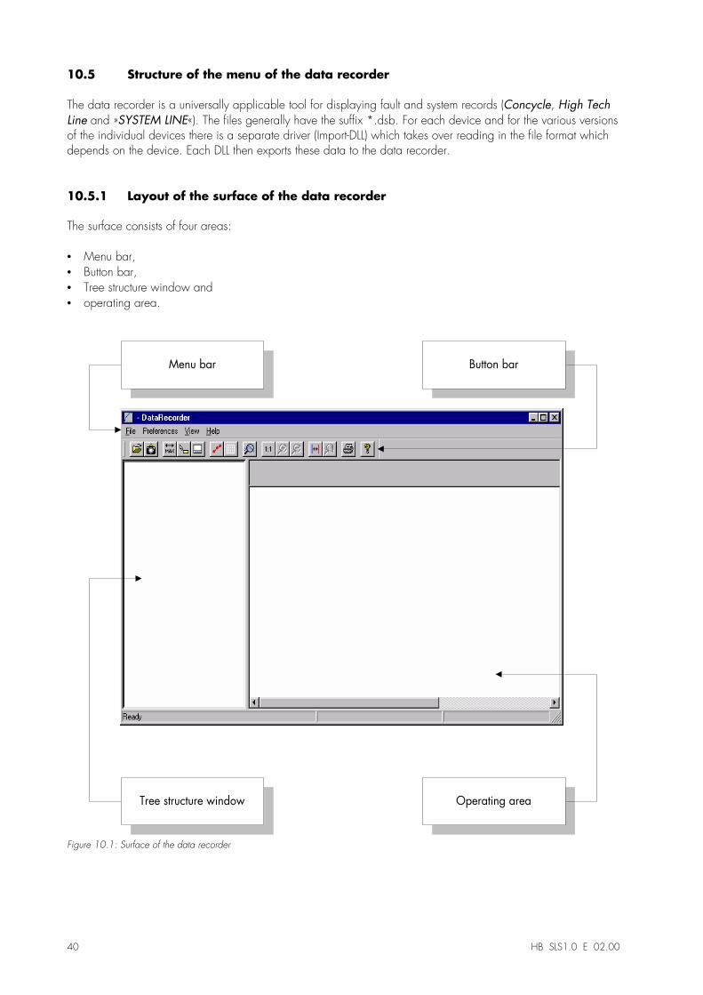
10.5 Structure of the menu of the data recorder
The data recorder is a universally applicable tool for displaying fault and system records (Concycle, High TechLine and »SYSTEM LINE«). The files generally have the suffix *.dsb. For each device and for the various versionsof the individual devices there is a separate driver (Import-DLL) which takes over reading in the file format whichdepends on the device. Each DLL then exports these data to the data recorder.
10.5.1 Layout of the surface of the data recorder
The surface consists of four areas:
•� Menu bar,•� Button bar,•� Tree structure window and•� operating area.
Menu bar Button bar
Tree structure window Operating area
Figure 10.1: Surface of the data recorder
HB SLS1.0 D 08.99 41
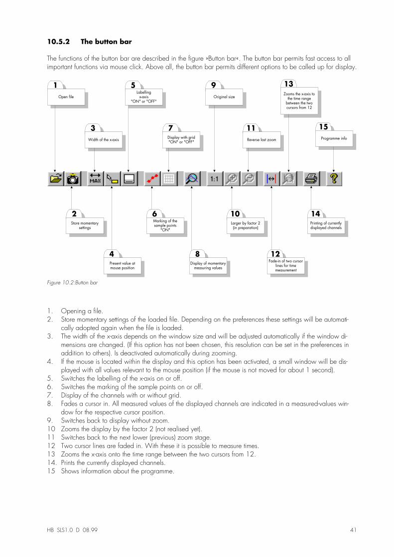
10.5.2 The button bar
The functions of the button bar are described in the figure »Button bar«. The button bar permits fast access to allimportant functions via mouse click. Above all, the button bar permits different options to be called up for display.
15
14
8
7
6
5
4
3
2
1
Open file
Store momentarysettings
Width of the x-axis
Present value atmouse position
Labellingx-axis
"ON" or "OFF"
Marking of thesample points
"ON"
Display with grid"ON" or "OFF"
Display of momentarymeasuring values
Printing of currentlydisplayed channels
Programme info
13
Zooms the x-axis tothe time range
between the twocursors from 12
9
Original size
10
Larger by factor 2(in preparation)
11
Reverse last zoom
12Fade-in of two cursor
lines for timemeasurement
Figure 10.2:Button bar
1. Opening a file.2. Store momentary settings of the loaded file. Depending on the preferences these settings will be automati-
cally adopted again when the file is loaded.3. The width of the x-axis depends on the window size and will be adjusted automatically if the window di-
mensions are changed. (If this option has not been chosen, this resolution can be set in the preferences inaddition to others). Is deactivated automatically during zooming.
4. If the mouse is located within the display and this option has been activated, a small window will be dis-played with all values relevant to the mouse position (if the mouse is not moved for about 1 second).
5. Switches the labelling of the x-axis on or off.6. Switches the marking of the sample points on or off.7. Display of the channels with or without grid.8. Fades a cursor in. All measured values of the displayed channels are indicated in a measured-values win-
dow for the respective cursor position.9. Switches back to display without zoom.10 Zooms the display by the factor 2 (not realised yet).11 Switches back to the next lower (previous) zoom stage.12 Two cursor lines are faded in. With these it is possible to measure times.13 Zooms the x-axis onto the time range between the two cursors from 12.14. Prints the currently displayed channels.15 Shows information about the programme.
42 HB SLS1.0 E 02.00
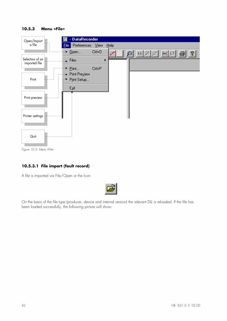
10.5.3 Menu »File«
Printer settings
Print preview
Selection of animported file
Open/Importa file
Quit
Figure 10.3: Menü »File«
10.5.3.1 File import (fault record)
A file is imported via File/Open or the Icon
On the basis of the file type (producer, device and internal version) the relevant DLL is reloaded. If the file hasbeen loaded successfully, the following picture will show:
HB SLS1.0 D 08.99 43
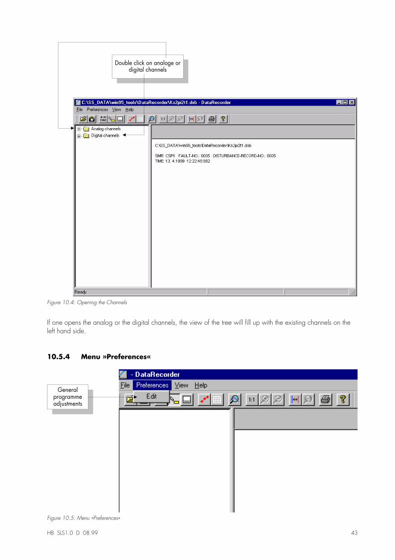
Double click on analoge ordigital channels
Figure 10.4: Opening the Channels
If one opens the analog or the digital channels, the view of the tree will fill up with the existing channels on theleft hand side.
10.5.4 Menu »Preferences«
Generalprogrammeadjustments
Figure 10.5: Menu »Preferences«
44 HB SLS1.0 E 02.00
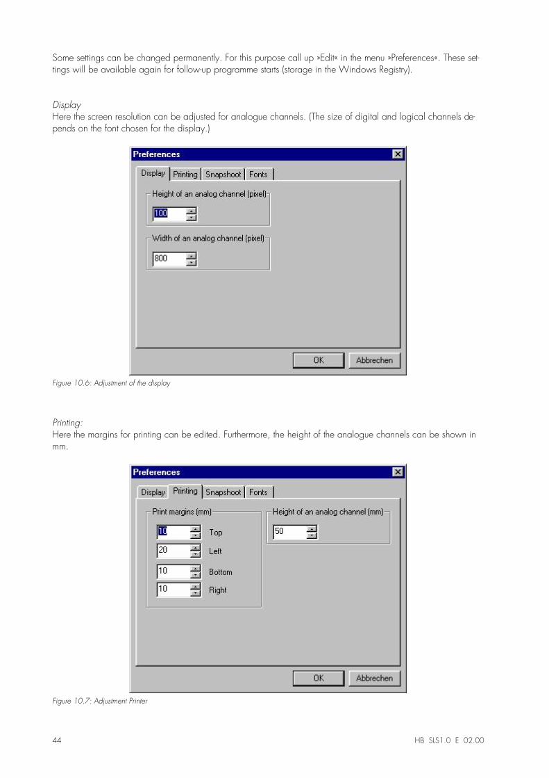
Some settings can be changed permanently. For this purpose call up »Edit« in the menu »Preferences«. These set-tings will be available again for follow-up programme starts (storage in the Windows Registry).
DisplayHere the screen resolution can be adjusted for analogue channels. (The size of digital and logical channels de-pends on the font chosen for the display.)
Figure 10.6: Adjustment of the display
Printing:Here the margins for printing can be edited. Furthermore, the height of the analogue channels can be shown inmm.
Figure 10.7: Adjustment Printer
HB SLS1.0 D 08.99 45
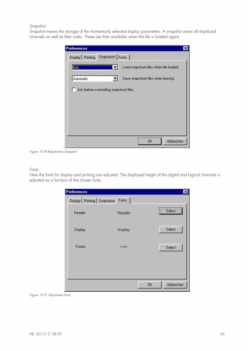
SnapshotSnapshot means the storage of the momentarily selected display parameters. A snapshot stores all displayedchannels as well as their order. These are then available when the file is loaded again.
Figure 10.8:Adjustments Snapshot
FontsHere the fonts for display and printing are adjusted. The displayed height of the digital and logical channels isadjusted as a function of the chosen fonts.
Figure 10.9: Adjustment fonts
46 HB SLS1.0 E 02.00
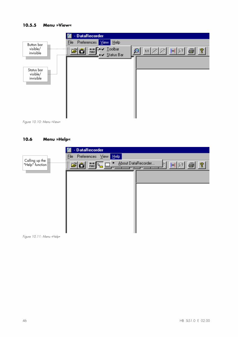
10.5.5 Menu »View«
Button barvisible/invisible
Status barvisible/invisible
Figure 10.10: Menu »View«
10.6 Menu »Help«
Calling up the"Help" function
Figure 10.11: Menu »Help«
HB SLS1.0 D 08.99 47
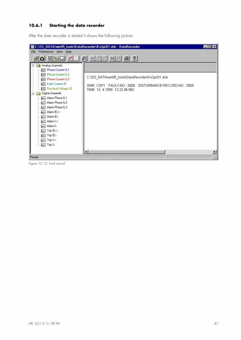
10.6.1 Starting the data recorder
After the data recorder is started it shows the following picture:
Figure 10.12: Fault record
48 HB SLS1.0 E 02.00
10.7 The tree structure of the data recorder
10.7.1 Important information on the function of the mouse
•� If the mouse is not moved inside the operating window, the appertaining sample number and time areshown. If the respective button is active, the measured values of the channel underneath the mouse will bedisplayed.
•� If the mouse position gets near the cursors (Button bar 8 or 11) the pointer changes and these cursor linescan be shifted by keeping the left mouse button suppressed.
•� If the left mouse button is pressed on a display, a section can be zoomed. If the mouse is moved while theleft mouse button is being pressed, it is possible to fix the section to be zoomed. There are two cursorswhich indicate during marking whether this zoom rate is permissible. (Zoom OK, Zooming not possibleas this would exceed the maximum resolution of 32.000 * 32.000 pixels.) Zooming can be abortedwith the "ESC" key.
•� If the right hand mouse key is pressed and the display is larger than the screen section, the mouse pointerchanges into a hand. This way, the shown section can be shifted.
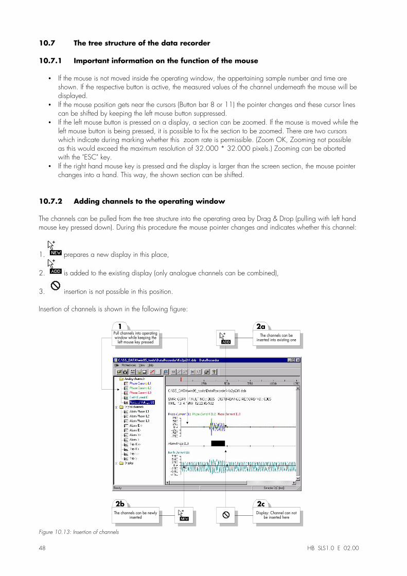
10.7.2 Adding channels to the operating window
The channels can be pulled from the tree structure into the operating area by Drag & Drop (pulling with left handmouse key pressed down). During this procedure the mouse pointer changes and indicates whether this channel:
1. prepares a new display in this place,
2. is added to the existing display (only analogue channels can be combined),
3. insertion is not possible in this position.
Insertion of channels is shown in the following figure:
2a
The channels can beinserted into existing one
1Pull channels into operatingwindow while keeping the
left mouse key pressed
2b
The channels can be newlyinserted
2c
Display: Channel can notbe inserted here
Figure 10.13: Insertion of channels
HB SLS1.0 D 08.99 49
Further channels can be added by Drag & Drop.
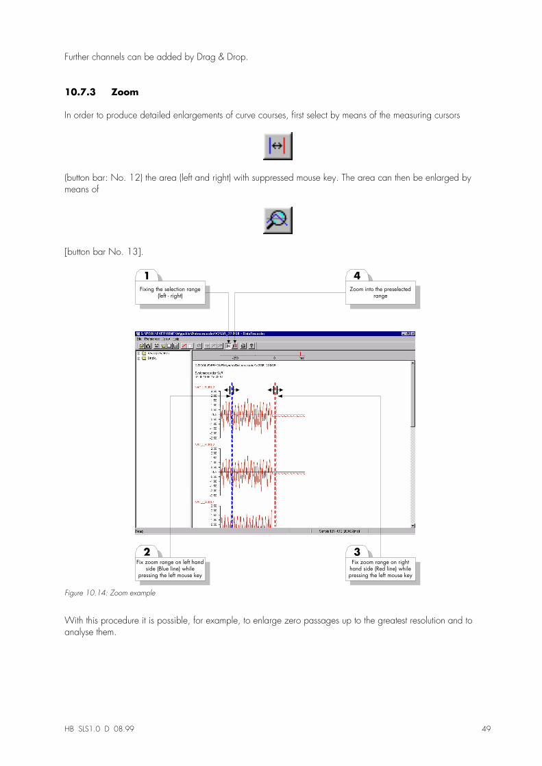
10.7.3 Zoom
In order to produce detailed enlargements of curve courses, first select by means of the measuring cursors
(button bar: No. 12) the area (left and right) with suppressed mouse key. The area can then be enlarged bymeans of
[button bar No. 13].
2
1
Fix zoom range on left handside (Blue line) while
pressing the left mouse key
Fixing the selection range(left - right)
3Fix zoom range on right
hand side (Red line) whilepressing the left mouse key
4
Zoom into the preselectedrange
Figure 10.14: Zoom example
With this procedure it is possible, for example, to enlarge zero passages up to the greatest resolution and toanalyse them.
50 HB SLS1.0 E 02.00
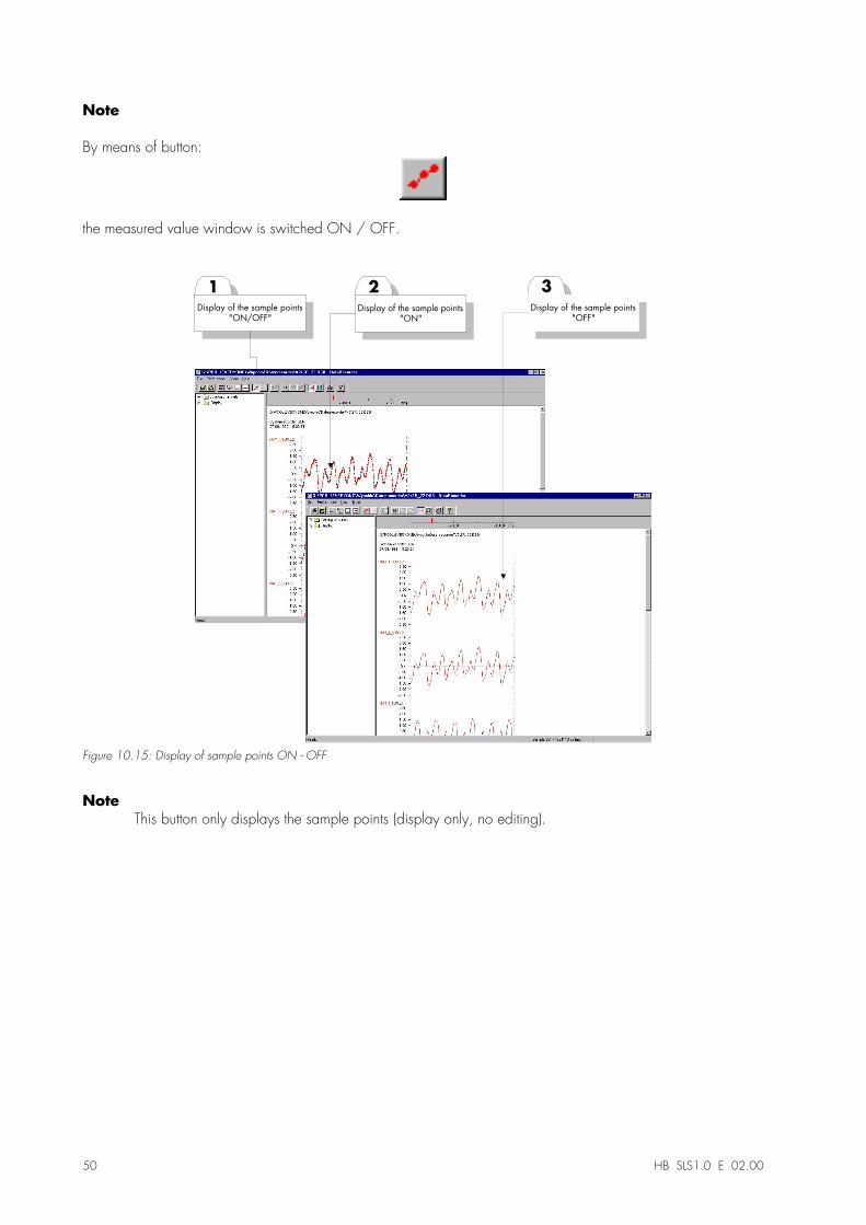
Note
By means of button:
the measured value window is switched ON / OFF.
1
Display of the sample points"ON/OFF"
3
Display of the sample points"OFF"
2
Display of the sample points"ON"
Figure 10.15: Display of sample points ON - OFF
NoteThis button only displays the sample points (display only, no editing).
HB SLS1.0 D 08.99 51
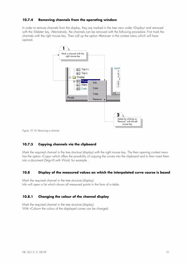
10.7.4 Removing channels from the operating window
In order to remove channels from the display, they are marked in the tree view under »Display« and removedwith the »Delete« key. Alternatively, the channels can be removed with the following procedure: First mark thechannels with the right mouse key. Then call up the option »Remove« in the context menu which will haveopened.
2
1
Delete by clicking on"Remove" with the left
mouse key
Mark a channel with theright mouse key
Figure 10.16: Removing a channel
10.7.5 Copying channels via the clipboard
Mark the required channel in the tree structure (display) with the right mouse key. The then opening context menuhas the option »Copy« which offers the possibility of copying the curves into the clipboard and to then insert theminto a document (Strg+V) with Word, for example. .
10.8 Display of the measured values on which the interpolated curve course is based
Mark the required channel in the tree structure (display).Info will open a list which shows all measured points in the form of a table.
10.8.1 Changing the colour of the channel display
Mark the required channel in the tree structure (display).With »Colour« the colour of the displayed curves can be changed.
52 HB SLS1.0 E 02.00
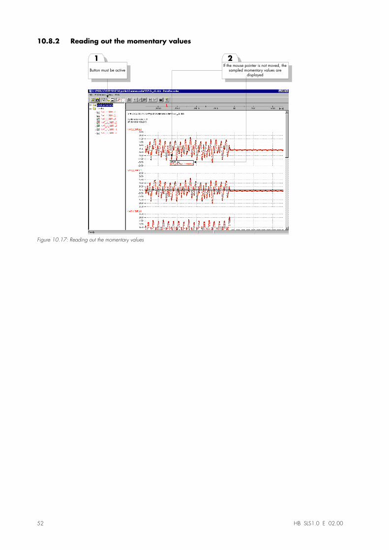
10.8.2 Reading out the momentary values
2If the mouse pointer is not moved, the
sampled momentary values aredisplayed
1
Button must be active
Figure 10.17: Reading out the momentary values
HB SLS1.0 D 08.99 53
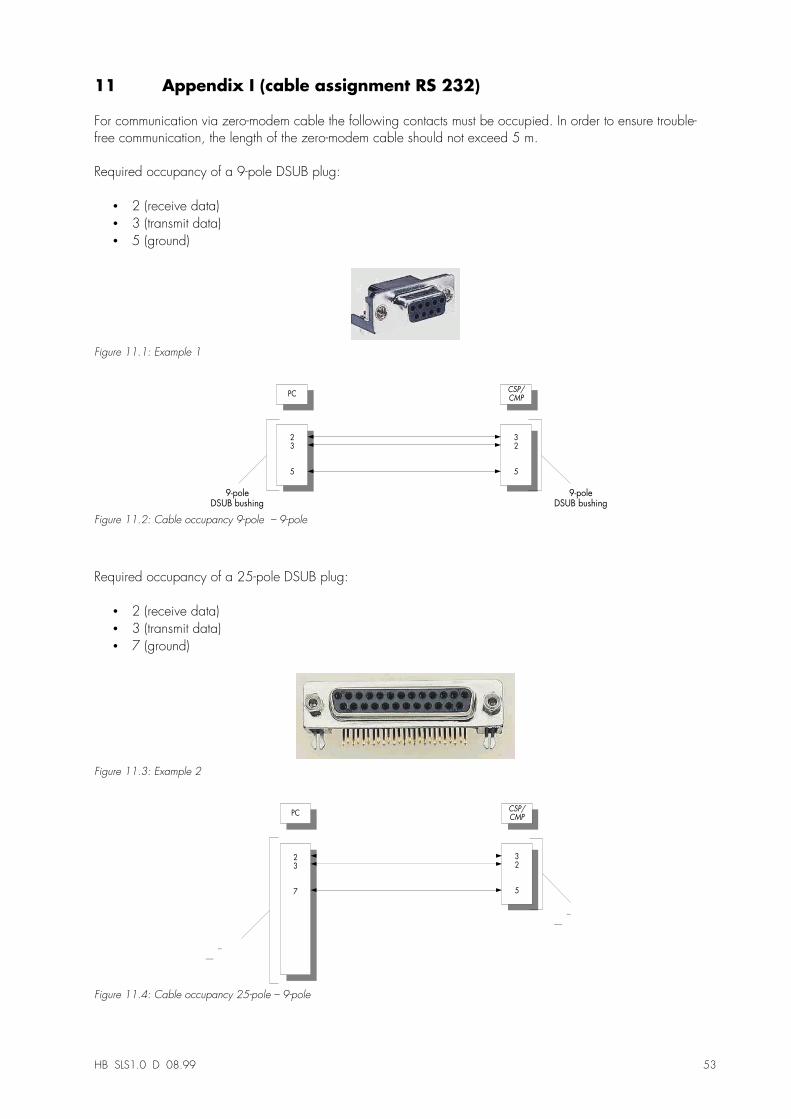
11 Appendix I (cable assignment RS 232)
For communication via zero-modem cable the following contacts must be occupied. In order to ensure trouble-free communication, the length of the zero-modem cable should not exceed 5 m.
Required occupancy of a 9-pole DSUB plug:
•� 2 (receive data)•� 3 (transmit data)•� 5 (ground)
Figure 11.1: Example 1
23
5
32
5
PC CSP/CMP
9-poleDSUB bushing
9-poleDSUB bushing
Figure 11.2: Cable occupancy 9-pole � 9-pole
Required occupancy of a 25-pole DSUB plug:
•� 2 (receive data)•� 3 (transmit data)•� 7 (ground)
Figure 11.3: Example 2
2
3
7
3
2
5
PCCSP/CMP
25-pole
DSUB bushing
25-pole
DSUB bushing
Figure 11.4: Cable occupancy 25-pole � 9-pole
54 HB SLS1.0 E 02.00
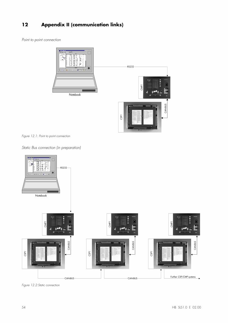
12 Appendix II (communication links)
Point to point connection
CA
N-B
US
CSP1
CMP1
Notebook
RS232
Figure 12.1: Point to point connection
Static Bus connection (in preparation)
CAN-BUS
CSP1
CM
P1
Notebook
RS232
CAN-BUS
CSP1
CM
P1
CAN-BUS
CSP1
CM
P1
CAN-BUS CAN-BUSFurther CSP/CMP systems
Figure 12.2:Static connection
HB SLS1.0 D 08.99 55
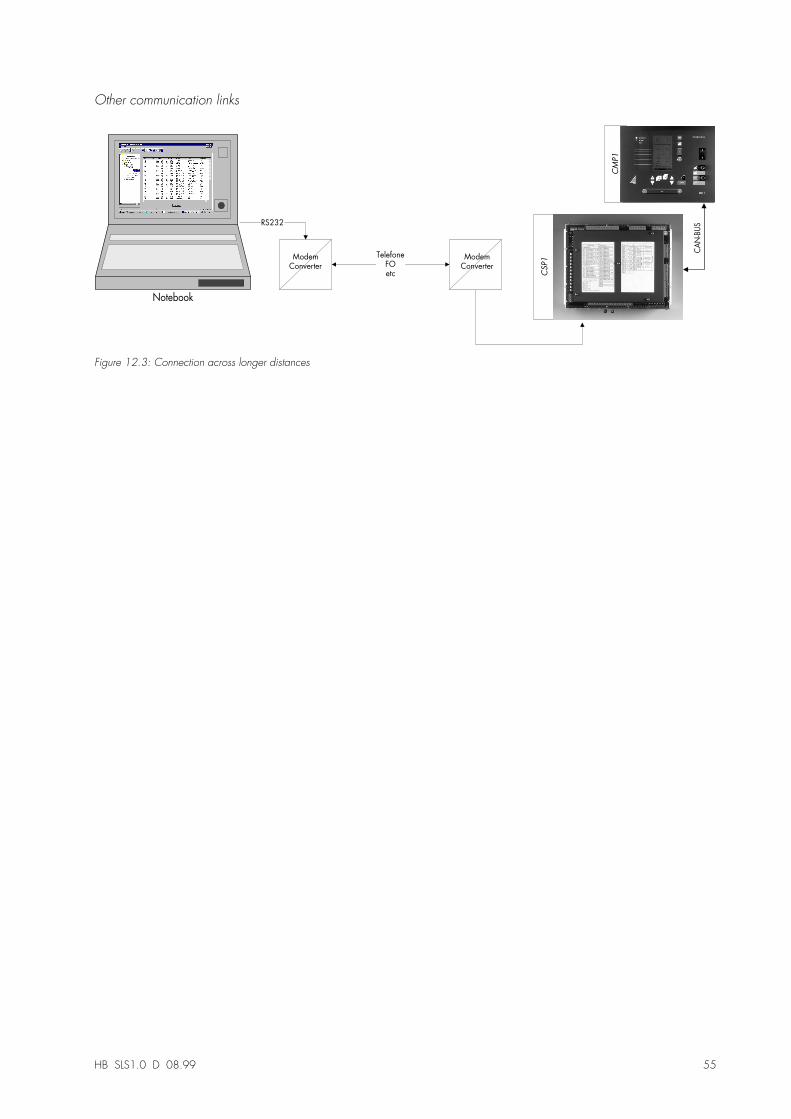
Other communication links
CAN-BUS
CSP1
CM
P1
Notebook
RS232
TelefoneFOetc
ModemConverter
ModemConverter
Figure 12.3: Connection across longer distances
56 HB SLS1.0 E 02.00
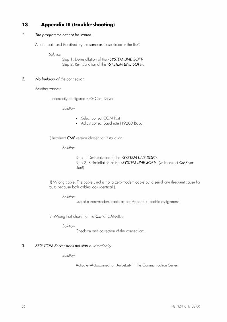
13 Appendix III (trouble-shooting)
1. The programme cannot be started:
Are the path and the directory the same as those stated in the link?
SolutionStep 1: De-installation of the »SYSTEM LINE SOFT«.Step 2: Re-installation of the »SYSTEM LINE SOFT«.
2. No build-up of the connection
Possible causes:
I) Incorrectly configured SEG Com Server
Solution
•� Select correct COM Port•� Adjust correct Baud rate (19200 Baud)
II) Incorrect CMP version chosen for installation
Solution
Step 1: De-installation of the »SYSTEM LINE SOFT«.Step 2: Re-installation of the »SYSTEM LINE SOFT«. (with correct CMP ver-sion!)
III) Wrong cable. The cable used is not a zero-modem cable but a serial one (frequent cause forfaults because both cables look identical!).
SolutionUse of a zero-modem cable as per Appendix I (cable assignment).
IV) Wrong Port chosen at the CSP or CAN-BUS
SolutionCheck on and correction of the connections.
3. SEG COM Server does not start automatically
Solution
Activate »Autoconnect on Autostart« in the Communication Server
HB SLS1.0 D 08.99 57
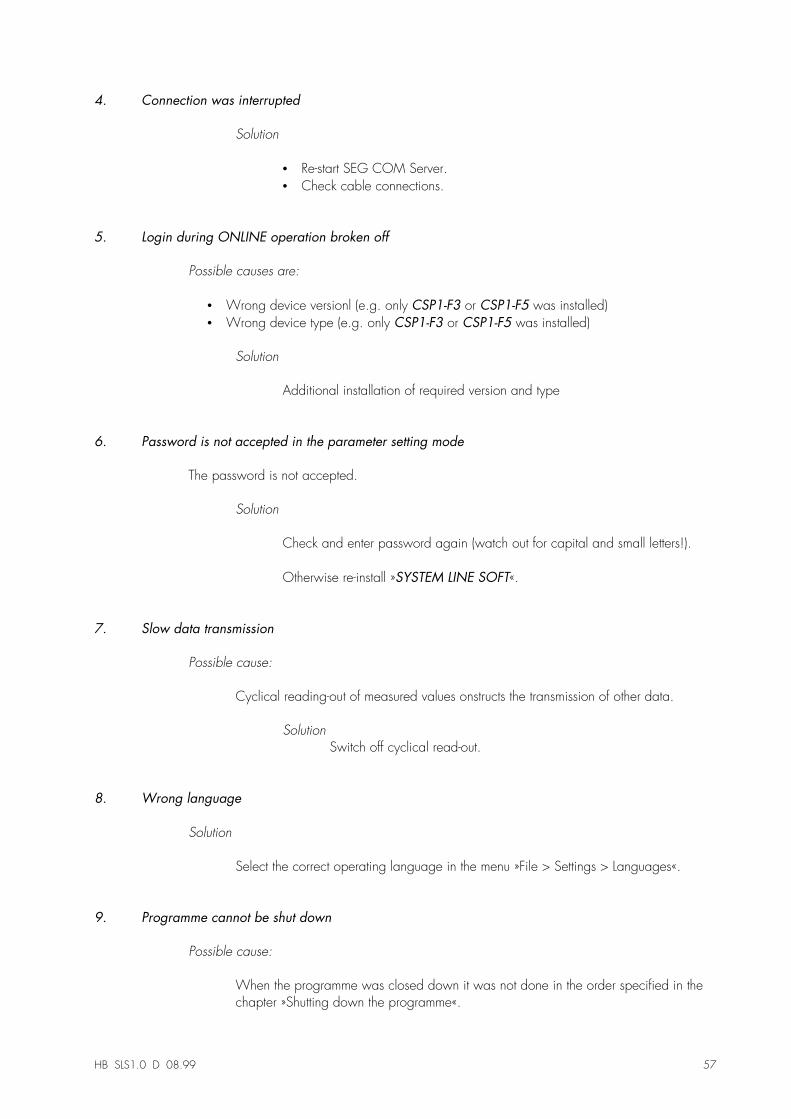
4. Connection was interrupted
Solution
•� Re-start SEG COM Server.•� Check cable connections.
5. Login during ONLINE operation broken off
Possible causes are:
•� Wrong device versionl (e.g. only CSP1-F3 or CSP1-F5 was installed)•� Wrong device type (e.g. only CSP1-F3 or CSP1-F5 was installed)
Solution
Additional installation of required version and type
6. Password is not accepted in the parameter setting mode
The password is not accepted.
Solution
Check and enter password again (watch out for capital and small letters!).
Otherwise re-install »SYSTEM LINE SOFT«.
7. Slow data transmission
Possible cause:
Cyclical reading-out of measured values onstructs the transmission of other data.
SolutionSwitch off cyclical read-out.
8. Wrong language
Solution
Select the correct operating language in the menu »File > Settings > Languages«.
9. Programme cannot be shut down
Possible cause:
When the programme was closed down it was not done in the order specified in thechapter »Shutting down the programme«.
58 HB SLS1.0 E 02.00
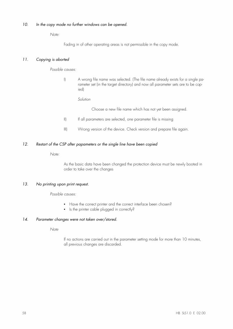
10. In the copy mode no further windows can be opened.
Note:
Fading in of other operating areas is not permissible in the copy mode.
11. Copying is aborted
Possible causes:
I)� A wrong file name was selected. (The file name already exists for a single pa-rameter set (in the target directory) and now all parameter sets are to be cop-ied)
Solution
Choose a new file name which has not yet been assigned.
II)� If all parameters are selected, one parameter file is missing
III)� Wrong version of the device. Check version and prepare file again.
12. Restart of the CSP after papameters or the single line have been copied
Note:
As the basic data have been changed the protection device must be newly booted inorder to take over the changes
13. No printing upon print request.
Possible causes:
•� Have the correct printer and the correct interface been chosen?•� Is the printer cable plugged in correctly?
14. Parameter changes were not taken over/stored.
Note
If no actions are carried out in the parameter setting mode for more than 10 minutes,all previous changes are discarded.
HB SLS1.0 D 08.99 59
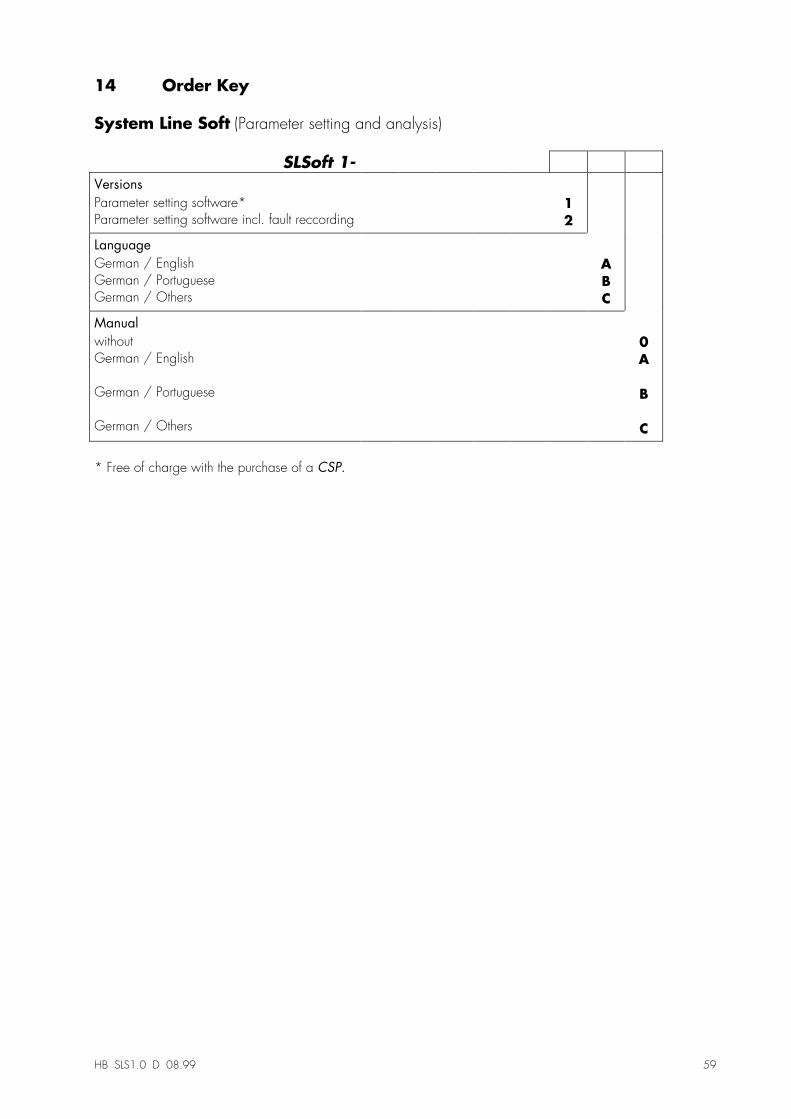
14 Order Key
System Line Soft (Parameter setting and analysis)
SLSoft 1-
Versions
Parameter setting software*Parameter setting software incl. fault reccording
12
Language
German / EnglishGerman / PortugueseGerman / Others
ABC
Manual
withoutGerman / English
German / Portuguese
German / Others
0A
B
C
* Free of charge with the purchase of a CSP.

This description is temporary. It is subject to continuous further revision without priornotice. In case of questions please contact: