Embed Size (px)
Citation preview

All parts of this document are the property of Saeco International Group.All rights reserved. This document and all the information herein is provided without liability deriving from any errors or omissions. Furthermore, no part may be reproduced, used or collected, except where express authorisation has been provided in writing or through a contractual agreement.
Published by Saeco International Group Subject to modifi cation EN 4219 400 00014
ServiceServiceServiceService
Coff ee Machine HD 8753 HD 8751 HD 8752
Intelia
Table of contents Page1. Introduction
1.1. Documentation required 11.2. Tools and equipment required 11.3. Material 11.4. Safety warnings 11.5 Intelia range 21.6.1. External machine parts 31.6.2. Internal machine parts 4
2. Technical specifi cations
2.1. Technical specifi cations 12.2. Machine parameters and performance 2
3. User instructions
3.1. Intelia Cappuccino customer and programming menu
1
3.2. Intelia Focus and Class customer and programming menu
2
3.3. Operation, cleaning and maintenance 3
4. Operating logic
4.1. Water circuit 14.2. Coff ee cycle 34.3. Single microswitch 44.4. Temperature sensor 44.5. Coff ee grinder 54.6 Low bean level detection, dose quantity
adjustment, coff ee grinder blocked5
2011-Sept-30
Table of contents Page4.7. Dose self-learning (SAS) 64.8. Water level detection (water tank) 7 4.9. Descaling request 74.10. Water fi lter 8
4.11 Intelia Cappuccino milk carafe 8
5. Troubleshooting
5.1.1. Intelia Cappuccino test mode 15.1.2. Intelia Focus and Class Test mode 65.2. SteamOut 105.3. Error messages 11
6. Standard checks
6.1. Repair schedule 16.2. Service schedule 16.3. Final test 2
7. Disassembly
7.1. Intelia Cappuccino outer Shell 17.2. Intellia Class and Focus outer Shell 27.3. Coff ee grinder 27.4. Grinder blades 37.5. Coff ee grinder adjustment 47.6 Intelia Cappuccino three-way solenoid valve 47.7 Intelia Class and Focus two-way solenoid valve 57.8 Intelia Cappuccino carafe fi tting body 57.9 Pump 6
Service Service ManualManual
Rev. 01 September 2011
Saeco International Group Rev. 01 / September 2011 INTELIA
Table of contents Page
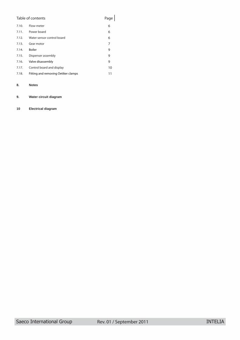
7.10. Flow-meter 6
7.11. Power board 6
7.12. Water sensor control board 6
7.13. Gear motor 7
7.14. Boiler 9
7.15. Dispenser assembly 9
7.16. Valve disassembly 9
7.17. Control board and display 10
7.18. Fitting and removing Oetiker clamps 11
8. Notes
9. Water circuit diagram
10 Electrical diagram

Saeco International Group Rev. 01 / September 2011 INTELIA
CHAPTER 1 INTRODUCTION
INTELIA 01 INTRODUCTION
Saeco International Group Rev. 01 / September 2011 Page / 05
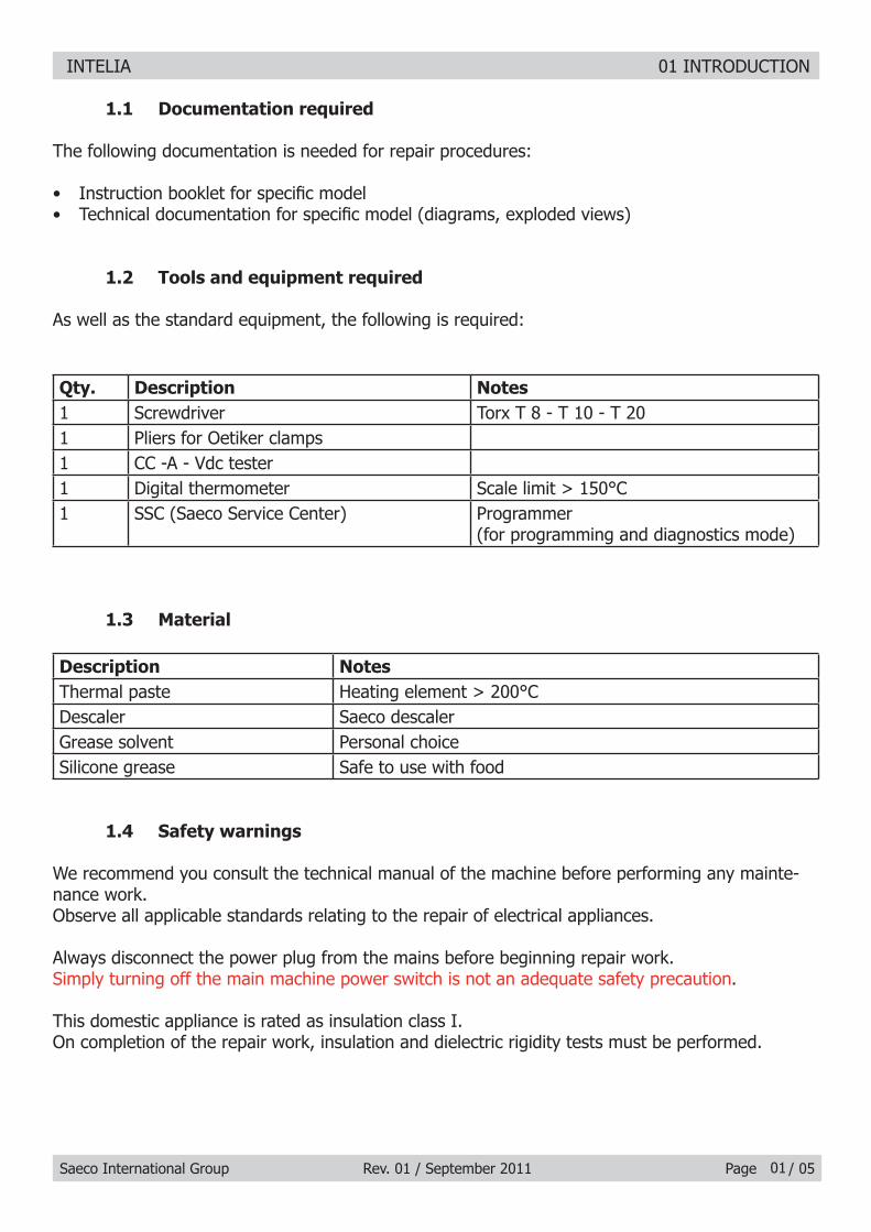
1.1 Documentation required
The following documentation is needed for repair procedures:
Instruction booklet for specifi c model• Technical documentation for specifi c model (diagrams, exploded views)•
1.2 Tools and equipment required
As well as the standard equipment, the following is required:
Qty. Description Notes1 Screwdriver Torx T 8 - T 10 - T 201 Pliers for Oetiker clamps 1 CC -A - Vdc tester1 Digital thermometer Scale limit > 150°C1 SSC (Saeco Service Center) Programmer
(for programming and diagnostics mode)
1.3 Material
Description NotesThermal paste Heating element > 200°CDescaler Saeco descalerGrease solvent Personal choiceSilicone grease Safe to use with food
1.4 Safety warnings
We recommend you consult the technical manual of the machine before performing any mainte-nance work.Observe all applicable standards relating to the repair of electrical appliances.
Always disconnect the power plug from the mains before beginning repair work.Simply turning off the main machine power switch is not an adequate safety precaution.
This domestic appliance is rated as insulation class I.On completion of the repair work, insulation and dielectric rigidity tests must be performed.
01

INTELIA 01 INTRODUCTION
Saeco International Group Rev. 01 / September 2011 Page / 05
1.5. Intelia range
Cappuccino Class FocusLed interface display x x xThermoplastic parts x x xMilk carafe xCappuccino maker xPannarello (frother) xAutomatic dosing (SAS) x x xDispensed coffee memory capacity x x xAutomatic shutdown (after 30’ inactivity) x x xAutomatic descaling cycle x x xHeight adjustable dispenser x x xCup stand x x xRemovable dispenser x x xAutomatic descaling cycle x x xDrip tray presence sensor x x x
02
CLASS
FOCUS
CAPPUCCINO

INTELIA 01 INTRODUCTION
Saeco International Group Rev. 01 / September 2011 Page / 0503
1.6.1 External machine parts
Coffee bean hopper with lid
Dreg drawer
Power cable socket and main switch
Grinding adjustment
Control panel
Milk carafe
Water dispenser(removable)
Intelia Cappuccino
Pre-ground coffee compartment
Coffee dispenser
Brewing unit
Water tank
Drip tray release button
Display
cappuccino button
ON/OFF buttonEspresso dispensing button
Long espresso dispensing button
Hot water/steam selection button MENU
button
Aroma / Pre-ground button
Drip tray+grille
Service hatch

INTELIA 01 INTRODUCTION
Saeco International Group Rev. 01 / September 2011 Page / 0504
Drip tray+grille
Coffee bean hopper with lid
Hot water/steam dispensing pipe
Pannarello(Intelia Focus)
Cappuccino valve (Intelia Class)
Dreg drawer
Power cable socket and main switch
Control panel
Pre-ground coffee compartment
Coffee dispenser
Service hatch
Brewing unit
Water tank
Display
ON/OFF buttonEspresso dispensing buttonLong espresso dispensing button
Hot water/steam selection button
MENU button
Descaling buttonIntelia Focus
Aroma / Pre-ground button
Intelia Class e Focus

INTELIA 01 INTRODUCTION
Saeco International Group Rev. 01 / September 2011 Page / 05
1.6.2 Internal machine parts
05
Boiler pin
Pump
Flow-meter
Power cable connector
Safety valve Boiler cover and boiler
Power board
Grinding adjustment insert
Steam pipe
KYB Interface card
2-way solenoid valve
Coffee grinder

Saeco International Group Rev. 01 / September 2011 INTELIA
CHAPTER 2 TECHNICAL
SPECIFICATIONS

INTELIA 02 TECHNICAL SPECIFICATIONS
Saeco International Group Rev. 01 / September 2011 Page / 03
2.1. Technical specifi cations
Power supply and output: 240 V~ 50 Hz 1850 W - 230 V~ 50/60 Hz 1850 W Temperature monitoring: (NTC) variable resistor sensor - transmits the value to the
electronic cardSafety system: 2 thermostats at 190°C one shotCoffee heat exchanger output: Stainless steel
(230 V~) 1900 W for coffee, hot water and steam dispensing
Steam heat exchanger output: Stainless steel As above
Gear motor: 2 rotation directions; power supply 24VCPump: Ulka Type EP5/S GW approx. 13-15 bar with reciprocating
piston and thermal switch 100°C 48 W, 230V, 50 Hz, 120V, 60Hz 100V, 50/60 Hz
Overpressure valve: Opening at approx. 16-18 barWater fi lter: In tank Coffee grinder: Direct current motor with fl at ceramic grinder blades Automatic dosage: Dose adjustment controlled by the electronic system Power consumption: During heating phase- approx. 5.6 ADimensions: W x H x D in mm: 256x340x440Weight: 9 kg Water tank capacity: 1.5 lCoffee bean hopper capacity: 300 g. of coffee beansDreg drawer capacity: 10Heat exchanger capacity: 10 (11 if after 9 dregs you dispense a double espresso)Water circuit fi lling time: Approx. 15 sec Max. on fi rst fi lling cycleHeating time: Approx. 45 sec.Dispensing temperature: Approx. 73°-83°Grinding time: Approx. 8-10 sec.
01

INTELIA 02 TECHNICAL SPECIFICATIONS
Saeco International Group Rev. 01 / September 2011 Page / 03
2.2. Machine parameters and performance
PRODUCT QUANTITY
Minimum quantity(Puls.)
Default quantity(Puls.)
Maximum quantity(Puls.)
User programmable
Programm. by Production /
ServiceEspresso 50 165 600 Yes No
Long coffee 70 440 600 Yes NoPre-ground NoHot water Continues until the water supply has been exhausted (capacitive sensor)
Steam pannarello (frother)
Continues until the water supply has been exhausted (capacitive sensor)
RINSE Initial rinse Final rinseWhen performed When the machine is switched
on and the boiler temperature is ≤ 50°C
When the machine is switched off electronically, manually or auto-matically after 30', if at least one coffee has been dispensed, be-
fore switching offNo. of pulses 180 80
Stopping option Yes, by pressing any key Yes, by pressing any keyUser disable option No No
Production/Service de-partment disable option No No
No. of pulses user adjust-ment option No No
No. of pulses Production/Service department ad-
justment optionNo No
Pulse range(Min. – Max.) No No
02
Descaling cycle frequencyHard-ness Water hardness Without water fi lter With water fi lter
1 Soft (up to 7°dH) 240 litres (480,000 pulses) 480 litres (960,000 pulses)2 Medium (7° - 14°dH) 120 litres (240,000 pulses) 240 litres (480,000 pulses)3 Hard (15° - 21°dH) 60 litres (120,000 pulses) 120 litres (240,000 pulses)4 Very hard (over 21°dH) 30 litres (60,000 pulses) 60 litres (120,000 pulses)
The default water hardness level is 4. Each litre of water corresponds to approximately 2,000 pulses.

INTELIA 02 TECHNICAL SPECIFICATIONS
Saeco International Group Rev. 01 / September 2011 Page / 03
WATER TANK DescriptionWater reserve (pulses) with water fi lter 200
Water reserve (pulses) with no water fi lter 200Water reserve modifi able by Production/Service
departmentsNo
"Fill tank" alarm Yes"No tray" alarm Yes (Fill tank)
Water mains No
DREG DRAWER Description and values
Time-out for dreg drawer 5 sec.
Reset dreg counter Dreg emptying alarm, if the dreg drawer is removed for more than 5 seconds.
STANDBY Description and valuesInlet time (default) 30 minutes
Inlet time programmed by Production/Serv-ice
Yes
Boiler temperature during Standby Boiler OFF
03

Saeco International Group Rev. 01 / September 2011 INTELIA
CHAPTER 3 USER INSTRUCTIONS

INTELIA 03 USER INSTRUCTIONS
Saeco International Group Rev. 01 / September 2011 Page / 05
3.1. Intelia Cappuccino customer and programming menu
01
If this screen appears after you switch the machine on, it means that you must run a descaling cycle.Press “ ” to access the descaling menu and consult the relative paragraph.Press “ ” to continue using the machine.
Notice signals (ORANGE)
Machine at correct temperature- for coffee bean dispensing- for hot water dispensingMachine at correct temperature- for ground bean dispensing
(pre-ground)
Hot water or hot milk selection
Hot water dispensing
Dispensing hot milk
Machine dispensing1 espresso
Machine dispensing2 espresso
Machine dispensing1 coffee
Machine dispensing2 coffees
The machine is being programmed with the coffee cup fi ll level
Machine in pre-heating phase for coffee, hot water and steam dispensing
The appliance is rinsing, wait until end of operation
The machine signals that the “INTENZA+” fi lter must be replaced
Brewing unit resetting during appliance reset
Fill the coffee bean container and start the dispensing cycle
Proceed to load the circuit
ON/OFF buttonespresso dispensing
buttonLong espresso
dispensing button
special beverages selection button cappuccino dispensing button
button MENU
Aroma button / Pre-ground button
Machine dispensing milk during the preparation of cappuccino
Machine dispensing coffee during the preparation of cappuccino
The machine is being programmed with the amount of milk to be dispensed to prepare cappuccino
The machine is being programmed with the amount of coffee to be dispensed to prepare cappuccino
MEMO
MEMO
MEMO
Machine ready signals (GREEN)
INTELIA 03 USER INSTRUCTIONS
Saeco International Group Rev. 01 / September 2011 Page / 0502
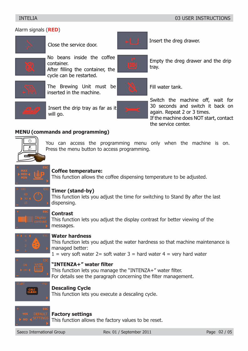
Alarm signals (RED)
MENU (commands and programming)
Close the service door.
No beans inside the coffee container.After fi lling the container, the cycle can be restarted.
The Brewing Unit must be inserted in the machine.
Insert the dreg drawer.
Empty the dreg drawer and the drip tray.
Fill water tank.
Insert the drip tray as far as it will go.
You can access the programming menu only when the machine is on.Press the menu button to access programming.
Coffee temperature:This function allows the coffee dispensing temperature to be adjusted.
Timer (stand-by)This function lets you adjust the time for switching to Stand By after the last dispensing.
ContrastThis function lets you adjust the display contrast for better viewing of the messages.
“INTENZA+” water fi lterThis function lets you manage the “INTENZA+” water fi lter. For details see the paragraph concerning the fi lter management.
Descaling CycleThis function lets you execute a descaling cycle.
Factory settingsThis function allows the factory values to be reset.
Water hardnessThis function lets you adjust the water hardness so that machine maintenance is managed better:1 = very soft water 2= soft water 3 = hard water 4 = very hard water
Switch the machine off, wait for 30 seconds and switch it back on again. Repeat 2 or 3 times.If the machine does NOT start, contact the service center.
ESC
-
+
Display contrast
ESC
-
+MAXMEDMIN
ESC
-
+
YES
NO
DEFAULT SETTINGS

INTELIA 03 USER INSTRUCTIONS
Saeco International Group Rev. 01 / September 2011 Page / 05
3.2. Intelia Focus and Class customer and programming menu
MEMO
03
ON/OFF buttonespresso dispensing button
Long espresso dispensing button
Hot water/steam selection button
Descaling button (Focus)
Aroma / Pre-ground button
If this screen appears after you switch the machine on, it means that you mustexecute a descaling cycle.Press “ ” to access the descaling menu and consult the relative paragraph.Press “ ” to continue using the machine.
Notice signals (ORANGE)
Machine at correct temperature- for coffee bean dispensing- for hot water dispensing
Machine at correct temperature- for pre-ground coffee dispensing
Hot water /steam selection
Water dispense pipe (spout)
Steam/water dispensing
Machine in phase for dispensing 1 cup of espresso
Machine in phase for dispensing 2 cups of espresso
Machine in phase for dispensing 1 cup of espresso
Machine in phase for dispensing 2 cups of espresso
The machine is being programmed with the coffee cup fi ll level
Machine in pre-heating phase for coffee, hot water and steam dispensing
The appliance is rinsing - wait until end of operation
The machine signals that the “INTENZA+” fi lter must be replaced
Brewing unit resetting during appliance reset
Fill the coffee bean container and start the dispensing cycle
Proceed to load the circuit
Machine ready signals (GREEN)
INTELIA 03 USER INSTRUCTIONS
Saeco International Group Rev. 01 / September 2011 Page / 0504
ESC
-
+
Display contrast
ESC
-
+MAXMEDMIN
ESC
-
+
YES
NO
DEFAULT SETTINGS
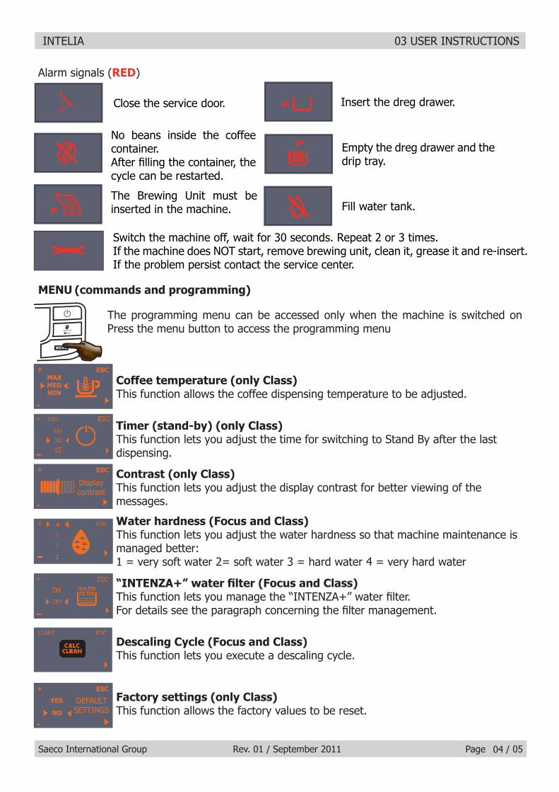
Alarm signals (RED)
MENU (commands and programming)
Close the service door.
No beans inside the coffee container.After fi lling the container, the cycle can be restarted.
The Brewing Unit must be inserted in the machine.
Insert the dreg drawer.
Empty the dreg drawer and the drip tray.
Fill water tank.
Switch the machine off, wait for 30 seconds. Repeat 2 or 3 times.If the machine does NOT start, remove brewing unit, clean it, grease it and re-insert. If the problem persist contact the service center.
The programming menu can be accessed only when the machine is switched on Press the menu button to access the programming menu
Coffee temperature (only Class)This function allows the coffee dispensing temperature to be adjusted.
Timer (stand-by) (only Class)This function lets you adjust the time for switching to Stand By after the last dispensing.
Contrast (only Class)This function lets you adjust the display contrast for better viewing of the messages.
“INTENZA+” water fi lter (Focus and Class)This function lets you manage the “INTENZA+” water fi lter.For details see the paragraph concerning the fi lter management.
Descaling Cycle (Focus and Class)This function lets you execute a descaling cycle.
Factory settings (only Class)This function allows the factory values to be reset.
Water hardness (Focus and Class)This function lets you adjust the water hardness so that machine maintenance is managed better:1 = very soft water 2= soft water 3 = hard water 4 = very hard water

INTELIA 03 USER INSTRUCTIONS
Saeco International Group Rev. 01 / September 2011 Page / 05
CLEANING AND TECHNICAL SERVICINGA Empty the dregs drawer When indicated
B Empty the drip tray As necessary
C Clean the water tank Weekly
D Clean the coffee bean hopper As necessary
E Clean the casing As necessary
F
Clean the brewing unit Every time the coffee bean hopper is fi lled or weekly
Lubricate the brewing unit After 500 dispensing cycles or when the grease is no longer present on the brewing unit
Clean the unit housing Weekly
H Descaling When indicated
Descaling cycle frequencyHardness Water hardness Without water fi lter With water fi lter
1 Soft (up to 7°dH) 240 litres (480,000 pulses) 480 litres (960,000 pulses)
2 Medium (7° - 14°dH) 120 litres (240,000 pulses) 240 litres (480,000 pulses)
3 Hard (15° - 21°dH) 60 litres (120,000 pulses) 120 litres (240,000 pulses)
4 Very hard (over 21°dH) 30 litres (60,000 pulses) 60 litres (120,000 pulses)
The default water hardness level is 3. Each litre of water corresponds to approximately 2,000 pulses
3.3. Operation, cleaning and maintenance
Operating the machine1 Fill water tank
2 Fill the coffee bean hopper
3 Switch on the appliance
4 Press the button to start the appliance
5 Heating When the heating phase begins, wait for it to fi nish
6 Rinse Carry out a rinse cycle for the internal circuits
7 Machine ready The machine is ready to dispense beverages
05

Saeco International Group Rev. 01 / September 2011 INTELIA
CHAPTER 4 OPERATING LOGIC

INTELIA 04 OPERATING LOGIC
Saeco International Group Rev. 01 / September 2011 Page / 08
4.1. Water circuit
01
Milk
car
afe
Com
pens
atio
n va
lve
wat
er o
utle
t
Flow
-met
er
1900
W b
oile
r
Wat
er
Hot
wat
er /
stea
m
Com
pens
atio
n va
lve
wat
er o
utle
t
Pum
p
Wat
er t
ank
Trad
ition
al w
ater
sys
tem
• Fl
ow m
eter
– A
mou
nt o
f co
ffee
disp
ense
d •
into
the
cup
Reci
proc
atin
g pi
ston
typ
e pu
mp
• (1
3 -
15 b
ar)
Com
pens
atio
n va
lve
• (o
peni
ng p
ress
ure
16 -
18
bar)
Boile
r –
1900
W•
Two-
way
sol
enoi
d va
lve
•
Thre
e-w
ay s
olen
oid
valv
e
Intelia Cappuccino
Brew
ing
unit
Thre
e-w
ay
sole
noid
val
ve

INTELIA 04 OPERATING LOGIC
Saeco International Group Rev. 01 / September 2011 Page / 08
Stea
m p
ipe
Com
pens
atio
n va
lve
wat
er o
utle
t
Flow
-met
er
1900
W b
oile
r
Wat
er
Hot
wat
er /
stea
m
Two-
way
sol
enoi
d va
lve
Pom
pa
Wat
er t
ank
Brew
ing
unit
Trad
ition
al w
ater
sys
tem
• Fl
ow m
eter
– A
mou
nt o
f co
ffee
dis-
• pe
nsed
into
the
cup
Reci
proc
atin
g pi
ston
typ
e pu
mp
• (1
3 -
15 b
ar)
Com
pens
atio
n va
lve
• (o
peni
ng p
ress
ure
16 -
18
bar)
Boile
r –
1900
W•
Two-
way
sol
enoi
d va
lve
•
Intelia Focus e Class
02

INTELIA 04 OPERATING LOGIC
Saeco International Group Rev. 01 / September 2011 Page / 08
Notes: * Only with Pre-brewing
4.2. Coffee cycle
Switching onWhen the machine is switched on, the gear motor repositions itself as follows:- It acts on microswitch 1 (see following chapter).- The gear motor changes its rotation direction and moves upwards again by approx. 1-2 mm.- The boiler begins to heat the water for approx. 45 sec., at full power, in order to reach the
optimal temperature. The temperature will then remain at a constant level.
Coffee cycleThe coffee grinder starts the grinding process (controlled by pulses generated by a sensor).1. The gear motor (brewing unit) moves to the brewing position.2. Preliminary dispensing phase (short pump activity, short pause).3. Product dispensing (the pump operation period is defi ned by the amount of product dis-4. pensed).The gear motor moves to its home position (the dregs are expelled automatically).5.
Main switch ON START STOP
Time
Coffee grinder
Heating
Pump
Brewing unit gear motor
Status Heating Ready Coffee cycle
Pulses (Dosage)
Pump operation (fl ow meter pulses) in
accordance with the amount of product
selected.
approx. 45 sec.
*
03
Single microswitch gear motor
StatusMicroswitch OFF ON

INTELIA 04 OPERATING LOGIC
Saeco International Group Rev. 01 / September 2011 Page / 08
An NTC is used as a temperature sensor; in the event of overheating this reduces boiler element power consumption.The electronic system detects the current boiler temperature from the drop in voltage of the sensor and adjusts it accordingly.Heating element values and corresponding temperatures: see table.
4.4. Temperature sensor (adjustment)
Temp. (°C) R nom (kΩ) ΔR (+/- %)20 61.465 8.650 17.599 5.975 7.214 4.180 6.121 3.785 5.213 3.490 4.459 3.1
100 3.3 2.5125 1.653 3.9150 0.893 5.1
4.3. Single microswitch
The gear motor is powered by a direct cur-rent motor that engages with the smaller double toothed wheel using a worm screw. The unit is mounted on the axle of the large gear wheel and when a coffee is requested, it moves from the standby position to the dis-pensing position, and then back to the stand-by position again.
- Standby position: 1
- Dispensing position: 2
2
1
04

INTELIA 04 OPERATING LOGIC
Saeco International Group Rev. 01 / September 2011 Page / 08
4.5. Coffee grinder
23
4
5
6
1
4.6. Low bean level detection, dose quantity adjustment, coffee grinder blocked
t1V
t2
t3
t4
t
Without beans n=100%
With beans n=100%
Without beans n=50%
With beans n=50%
The coffee grinder is driven by a direct current motor (1) using a worm screw helicoidal wheel transmission (2).The worm screw (2) drives a plastic gear wheel (3), which turns the lower grinder (4) and the increment pin (5) There are two magnets (6) in the gear wheel; at every rotation these induce two pulses to a Hall sensor, which in turn transmits them to the electronic system.
No coffeeA low coffee bean level is detected by the Hall sensor, after variations in the pulse frequency (with or without coffee). If there are no coffee beans (operation while empty), the number of rotations – and therefore the number of pulses – will be greater.t1 = no coffee indication
If, however, there are coffee beans, the number of rotations will be lower due to the force created by the grinding.t2 = no indication
t3 and t4 = this measurement is performed at the end of each grinding process
Dose quantity adjustmentThe dose quantity is adjusted in accordance with the pulses detected (number of rotations proportional to the selected fl avor – mild, medium or strong).Coffee grinder blockageIf the coffee grinder becomes blocked for any reason, pulses will no longer be transmitted to the electronic system and the grinder will come to a stop.
05

INTELIA 04 OPERATING LOGIC
Saeco International Group Rev. 01 / September 2011 Page / 08
4.7. Dose self-learning (SAS)
06
The aim of this function is to automatically regulate the average dose of ground coffee (SELF-LEARNING); this takes place with an algorithm based on three pieces of data that the machine receives via the card:
1. Number of coffee grinder pulses during the grinding cycle.2. Max. average value of the power consumed by the gear motor during the coffee brewing cycle.3. Aroma selected by the user.
The algorithm compares the maximum average value of the power consumed by the gear motor with the value listed in the table for the selected aroma, in order to calculate the new grinding pulse value for the next coffee produced.If the power consumption value is less than the minimum current value, the grinding pulses will be increased by 2.If the power consumption value is greater than the maximum current value, the grinding pulses will be decreased by 4.If the power consumption value falls within the “over-torque” interval, the product will be dis-pensed and the grinding pulses will be decreased by 10.If the power consumption value falls within the “abort cycle” interval, the dreg will be expelled and the grinding pulses will be decreased by 10.If the “pre-ground” fl avour is selected by the user, no modifi cation will be made.
This guarantees that, regardless of the coffee type used, the grinding level setting and the wear on the grinders, the ground coffee dose always remains constant.
Important:For perfect operation, machine adjustment should take place in the area of the fi elds highlighted in green (A, B, C). When the type or brand of coffee is changed, there may be variations in the size of the beans and their stickiness or roasting level. This leads to variations in power consumption (mA), with resulting excessive or insuffi cient doses (until the necessary adjustments have been made to compensate for this change).Caution: In the case of excessive dosage, powder may be expelled into the dreg drawer. This is not a fault, but can occur during preliminary operation or after a service.
Setting/Status Power consumption in mA
Pulses corrected in the next grinding process
In the event of absorp-tion above the range
In the event of absorp-tion below the range
A Mild aroma 200 - 300 mA - 4 +2
B Medium Aroma 301 - 450 mA - 4 +2
C Strong Aroma 451 - 600 mA - 4 +2
D Over-limit 601 - 800 mA - 4
E Overwork 801 - 1000 mA - 10
F Dreg expulsion > 1000 mA - 10

INTELIA 04 OPERATING LOGIC
Saeco International Group Rev. 01 / September 2011 Page / 08
4.8. Water level detection (water tank)
“Water low” message (water reserve)
Function:The water level is monitored by a capacitative sensor, located one third of the way up the water tank wall.If the electronics assembly detects, by means of the sensor, that the amount of water in the tank has dropped below the above mentioned level, a water reserve remains available for the dispensing process underway (this will cover 200 fl ow meter pulses).The product dispensing process will then come to an end.If a dispensing cycle ends after the sensor has been triggered (in the reserve) then the display “Water low” continues to be displayed during the following dispensing cycle.
200 puls.
Sensor
Water tank
07
“Descaling” – message with water fi lter inserted(appliances with display only)
The water hardness is set on the basis of the regional water hardness analysis (1, 2, 3, 4).
Filter off:If the function is turned off the electronics assembly monitors the fl ow meter pulses, recording one pulse each turn.
Filter on:If the function is turned on the electronics assembly monitors the fl ow meter pulses, recording one pulse every two turns.
“Change water fi lter” message The electronics assembly uses the fl ow meter impulses to keep track of the amount of water which has fl owed through; after the specifi ed amount (set in accordance with the water hardness level), the “Replace fi lter” message appears.
4.9. Descaling request
360°1 rev
Number of pulses
Filteron
Filteroff
Flow meter pulses
INTELIA 04 OPERATING LOGIC
Saeco International Group Rev. 01 / September 2011 Page / 08
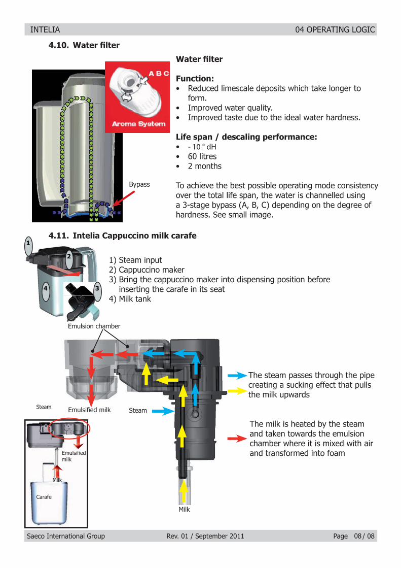
Water fi lter
Function: Reduced limescale deposits which take longer to • form. Improved water quality.• Improved taste due to the ideal water hardness.•
Life span / descaling performance: • - 10 ° dH 60 litres• 2 months•
To achieve the best possible operating mode consistency over the total life span, the water is channelled using a 3-stage bypass (A, B, C) depending on the degree of hardness. See small image.
Bypass
4.10. Water fi lter
08
1) Steam input2) Cappuccino maker3) Bring the cappuccino maker into dispensing position before
inserting the carafe in its seat4) Milk tank
4.11. Intelia Cappuccino milk carafe
The steam passes through the pipe creating a sucking effect that pulls the milk upwards
The milk is heated by the steam and taken towards the emulsion chamber where it is mixed with air and transformed into foam
Emulsifi ed milk
Emulsion chamber
Steam Steam
Emulsifi ed milk
Carafe
Milk
Milk
1
2
4 3
MiMiiilllM l

Saeco International Group Rev. 01 / September 2011 INTELIA
CHAPTER 5 TROUBLESHOOTING

INTELIA 05 TROUBLESHOOTING
Saeco International Group Rev. 01 / September 2011 Page / 11
5.1.1. Intelia Cappuccino test mode
Entry into Test Mode results in a screen divided into sections, as illustrated in the diagram below.Entry into Test Mode results in a screen divided into sections, as illustrated in the diagram below.Firmware Software versionFirmware Software version
Operational check – keysOperational check – keys
Operational check microswitches and sensorsOperational check microswitches and sensors
Shows the version of the fi rmware loaded and the internal checksum (it Shows the version of the fi rmware loaded and the internal checksum (it gives univocal traceability)gives univocal traceability)
Initial status Initial status
Initial status.Initial status.
The letter next to it changes from N to Y when only one button is pressed.The letter next to it changes from N to Y when only one button is pressed.By pressing buttons 1, 3, 4, 6 the display color changes from GREEN to RED. By pressing buttons 1, 3, 4, 6 the display color changes from GREEN to RED. By pressing buttons 2, 5 and 7 the display color changes from GREEN to By pressing buttons 2, 5 and 7 the display color changes from GREEN to YELLOW. YELLOW. Button 4 must be pressed at the end only once, since pressing it moves on to Button 4 must be pressed at the end only once, since pressing it moves on to the next page.the next page.
ERROR condition:ERROR condition:The letters do not change from N to Y or are always Y, in this case check the fl at communication The letters do not change from N to Y or are always Y, in this case check the fl at communication cable with the Control Board/Power Board, if it does not change color check the cable JP4 too.cable with the Control Board/Power Board, if it does not change color check the cable JP4 too.
Insert full water tankInsert full water tankThe TANK-H20 indicator must change from “N” to “Y” ERROR Condition:ERROR Condition:If the indication does not change, check the capacitive sensor and relative wiring If the indication does not change, check the capacitive sensor and relative wiring (JP23).(JP23).
01
To enter Test Mode Hold down the buttons Espresso 1. and Menu.Turn on the main switch at the 2. rear of the machine
1
2
Press STAND_BY “ Press STAND_BY “ ” to move to the next screen ” to move to the next screen
Insert the dreg drawerInsert the dreg drawerThe DREG indicator must change from “N” to “Y” The DREG indicator must change from “N” to “Y” ERROR Condition:ERROR Condition:If the indication does not change, check the microswitch on the dreg drawer If the indication does not change, check the microswitch on the dreg drawer and relative wiring (JP16).and relative wiring (JP16).
Press STAND_BY “ Press STAND_BY “ ” to move to the next screen ” to move to the next screen

INTELIA 05 TROUBLESHOOTING
Saeco International Group Rev. 01 / September 2011 Page / 1102
Close the side door (the dreg drawer must already be in position)Close the side door (the dreg drawer must already be in position)The DOOR indicator must change from “N” to “Y” The DOOR indicator must change from “N” to “Y” ERROR condition:ERROR condition:If the indication does not change, check the Microswitch on the hatch and If the indication does not change, check the Microswitch on the hatch and relative wiring (JP14), make sure that the dreg drawer is correctly in position.relative wiring (JP14), make sure that the dreg drawer is correctly in position.
Insert the brewing unitInsert the brewing unitThe BU-P indicator must change from “N” to “Y” The BU-P indicator must change from “N” to “Y” ERROR Condition:ERROR Condition:If the indication does not change, check the brewing unit microswitch and If the indication does not change, check the brewing unit microswitch and relative wiring (JP16).relative wiring (JP16).
Insert the dreg drawerInsert the dreg drawerThe TRAY indicator must change from “N” to “Y” The TRAY indicator must change from “N” to “Y” ERROR Condition:ERROR Condition:If the indication does not change, check the brewing unit microswitch and If the indication does not change, check the brewing unit microswitch and relative wiring (JP4).relative wiring (JP4).
Insert the CarafeInsert the CarafeThe CARAFE indicator must change from “N” to “Y” The CARAFE indicator must change from “N” to “Y” ERROR Condition:ERROR Condition:If the indication does not change, check the brewing unit microswitch and If the indication does not change, check the brewing unit microswitch and relative wiring (JP25).relative wiring (JP25).Insert the Water CouplingInsert the Water CouplingThe TAP indicator must change from “N” to “Y” The TAP indicator must change from “N” to “Y” ERROR Condition:ERROR Condition:If the indication does not change, check the brewing unit microswitch and If the indication does not change, check the brewing unit microswitch and relative wiring (JP25).relative wiring (JP25).
Initial statusInitial status
Operational check - milk inputs
Press STAND_BY “ Press STAND_BY “ ” to move to the next screen ” to move to the next screen
The COM indicator must be left on USCP.The COM indicator must be left on USCP.
Press STAND_BY “ Press STAND_BY “ ” to move to the next screen ” to move to the next screen
Operational check – brewing unit
Initial statusInitial status

INTELIA 05 TROUBLESHOOTING
Saeco International Group Rev. 01 / September 2011 Page / 1103
Press the ESPRESSO button to move the unit to Work position. When Press the ESPRESSO button to move the unit to Work position. When the unit is in position, the WORK indication changes from “N” to “Y”, the the unit is in position, the WORK indication changes from “N” to “Y”, the absorption current must be less than 200mA without the brewing unit on, absorption current must be less than 200mA without the brewing unit on, and less than 300mA with the brewing unit on.and less than 300mA with the brewing unit on.
The WORK indicator remains permanently on “N” The WORK indicator remains permanently on “N” ERROR condition:ERROR condition:The WORK indicator changes, and remains permanently on “N”, while the The WORK indicator changes, and remains permanently on “N”, while the backlight changes from green to red; check the microswitch, unit motor backlight changes from green to red; check the microswitch, unit motor (this may be blocked) and lastly the wiring JP16 and JP14.(this may be blocked) and lastly the wiring JP16 and JP14.
ERROR condition:ERROR condition:(without brewing unit):(without brewing unit):If the absorbed current exceeds 200 mA the display turns red, check the If the absorbed current exceeds 200 mA the display turns red, check the gears on the motor and the motor housing in its seat.gears on the motor and the motor housing in its seat.
ERROR condition: ERROR condition: (with brewing unit):(with brewing unit):If the absorbed current exceeds 300 mA the display turns red, check the If the absorbed current exceeds 300 mA the display turns red, check the brewing unit, the gears on the motor and the motor housing in its seat.brewing unit, the gears on the motor and the motor housing in its seat.
Press the COFFEE button to shift the unit into Home position. When the Press the COFFEE button to shift the unit into Home position. When the unit reaches HOME position the indication changes from “N” to “Y”, the unit reaches HOME position the indication changes from “N” to “Y”, the absorption current must be less than 200mA without the unit or less than absorption current must be less than 200mA without the unit or less than 300 mA with the unit on.300 mA with the unit on.
The HOME indicator remains permanently on “N” The HOME indicator remains permanently on “N” ERROR condition:ERROR condition:The HOME indicator changes, and remains permanently on “N”, while the The HOME indicator changes, and remains permanently on “N”, while the display changes from green to red; check the microswitch, unit motor (this display changes from green to red; check the microswitch, unit motor (this may be blocked) and lastly the wiring JP16 and JP14.may be blocked) and lastly the wiring JP16 and JP14.
ERROR condition:ERROR condition:(without brewing unit):(without brewing unit):If the absorbed current exceeds 200 mA the display turns red, check the If the absorbed current exceeds 200 mA the display turns red, check the gears on the motor and the motor housing in its seat.gears on the motor and the motor housing in its seat.
ERROR condition:ERROR condition:(with brewing unit):(with brewing unit):If the absorbed current exceeds 300 mA the display turns red, check the If the absorbed current exceeds 300 mA the display turns red, check the brewing unit, the gears on the motor and the motor housing in its seat.brewing unit, the gears on the motor and the motor housing in its seat.
Press STAND_BY “ Press STAND_BY “ ” to move to the next screen ” to move to the next screen

INTELIA 05 TROUBLESHOOTING
Saeco International Group Rev. 01 / September 2011 Page / 11
Operational check - coffee grinder and boiler
Initial StatusInitial Status
If the following screen appears it means that the dreg drawer is not If the following screen appears it means that the dreg drawer is not correctly inserted, or that the side door is not completely closed. The correctly inserted, or that the side door is not completely closed. The screen will disappear only after the drawer has been inserted or the door screen will disappear only after the drawer has been inserted or the door closed.closed.
Press the ESPRESSO button to activate solenoid valve EV1 (2-way, normally Press the ESPRESSO button to activate solenoid valve EV1 (2-way, normally closed).closed).The solenoid valve is activated and the indication to the right of EV1 The solenoid valve is activated and the indication to the right of EV1 changes from “OFF” to “ON”.changes from “OFF” to “ON”.
Press the COFFEE button to activate solenoid valve EV2 (3-way, normally Press the COFFEE button to activate solenoid valve EV2 (3-way, normally open).open).The solenoid valve is activated and the indication to the right of EV2 The solenoid valve is activated and the indication to the right of EV2 changes from “OFF” to “ON”.changes from “OFF” to “ON”.
Press the AROMA button to activate solenoid valve EV2 (3-way, normally Press the AROMA button to activate solenoid valve EV2 (3-way, normally open).open).The water is dispensed from the steam pipe. IMP indicates an increasing The water is dispensed from the steam pipe. IMP indicates an increasing number of pulses. L/H must be between 10 and 18.number of pulses. L/H must be between 10 and 18.
ERROR:ERROR:The pulses remain at 0, the display turns red, this means there is an error The pulses remain at 0, the display turns red, this means there is an error in the water circuit. If water is coming out of the coupling,it means there is in the water circuit. If water is coming out of the coupling,it means there is an error in the fl ow meter or in its wiring in the Control Board/Power Board an error in the fl ow meter or in its wiring in the Control Board/Power Board (JP5). If no water is coming out, check the pump, the connected water (JP5). If no water is coming out, check the pump, the connected water circuit, or the pump wiring (JP24).circuit, or the pump wiring (JP24).
Initial statusInitial status
Press Aroma to switch on the grinderPress Aroma to switch on the grinderThe coffee grinder starts to spin and the number of pulses is indicated by The coffee grinder starts to spin and the number of pulses is indicated by the number circled in red, the other numbers have no signifi cance for this the number circled in red, the other numbers have no signifi cance for this test.test.
04
Press STAND_BY “ Press STAND_BY “ ” to move to the next screen ” to move to the next screen
Operational check - solenoid valves and pump

INTELIA 05 TROUBLESHOOTING
Saeco International Group Rev. 01 / September 2011 Page / 1105
ERROR:ERROR:If the number remains 0, the display turns red, and the motor is run-If the number remains 0, the display turns red, and the motor is run-ning, the problem lies in the Hall sensors, or their wiring, or in the Control ning, the problem lies in the Hall sensors, or their wiring, or in the Control Board/Power Board input (JP2). If the motor does not run, the problem Board/Power Board input (JP2). If the motor does not run, the problem may lie in the chain (JP8), the coffee grinder wiring or the actual coffee may lie in the chain (JP8), the coffee grinder wiring or the actual coffee grinder.grinder.
Temperature controlTemperature controlThe circled number expresses the boiler temperature in degrees centi-The circled number expresses the boiler temperature in degrees centi-grade.grade.
ERROR:ERROR:If the HEATER indicator shows the word “SHORT”, this means that the If the HEATER indicator shows the word “SHORT”, this means that the NTC temperature sensor is in short circuit and the display turns from NTC temperature sensor is in short circuit and the display turns from green to red. In this case, check the wiring of the NTC or the Control green to red. In this case, check the wiring of the NTC or the Control Board/Power Board (JP13).Board/Power Board (JP13).
ERROR:ERROR:If the HEATER indicator shows the word “OPEN”, this means that the If the HEATER indicator shows the word “OPEN”, this means that the NTC temperature sensor is disconnected, the display turns from green NTC temperature sensor is disconnected, the display turns from green to red.to red.In this case, check the continuity of the NTC wiring and check the con-In this case, check the continuity of the NTC wiring and check the con-nection to the Control Board/Power Board (JP13).nection to the Control Board/Power Board (JP13).
Press the COFFEE button to activate the BoilerPress the COFFEE button to activate the BoilerThe indicator changes from “OFF” to “ON” and shortly after the tempera-The indicator changes from “OFF” to “ON” and shortly after the tempera-ture indicator should start to increase, and any ammeter at the techni-ture indicator should start to increase, and any ammeter at the techni-cian’s disposal on the counter must display an absorption of approximate-cian’s disposal on the counter must display an absorption of approximate-ly 8 Ampere with 230 volt.ly 8 Ampere with 230 volt.
ERROR:ERROR:If the temperature is not absorbed check the boiler resistor, relative wiring If the temperature is not absorbed check the boiler resistor, relative wiring and the connection to the Control Board/Power Board input (JP19), also and the connection to the Control Board/Power Board input (JP19), also check the wiring on the NTC (JP13).check the wiring on the NTC (JP13).
If the temperature goes above 125°C then the display turns yellow and If the temperature goes above 125°C then the display turns yellow and an alarm message appears on the display. an alarm message appears on the display. Above this temperature the boiler is always off, avoiding the risk of dan-Above this temperature the boiler is always off, avoiding the risk of dan-gerously high temperatures.gerously high temperatures.

INTELIA 05 TROUBLESHOOTING
Saeco International Group Rev. 01 / September 2011 Page / 11
5.1.2. Intelia Focus and Class Test mode
1
2
06
Entry into Test Mode results in a screen divided into sections, as illustrated in the diagram below.Entry into Test Mode results in a screen divided into sections, as illustrated in the diagram below.
To enter Test Mode Hold down the Espresso and 1. Menu buttons.Switch on the main switch at 2. the back of the machine.
Firmware Software versionFirmware Software version
Operational check – keysOperational check – keys
Operational check microswitches and sensorsOperational check microswitches and sensors
Shows the version of the fi rmware loaded for Focus and Class.Shows the version of the fi rmware loaded for Focus and Class.
Initial status Initial status
Initial status.Initial status.
The letter next to it changes from N to Y only when a button is pressed.The letter next to it changes from N to Y only when a button is pressed.By pressing buttons 1, 3, 4, 6 the display color changes from GREEN to RED.By pressing buttons 1, 3, 4, 6 the display color changes from GREEN to RED.By pressing buttons 2, 5, the display color changes from GREEN to YELLOW.By pressing buttons 2, 5, the display color changes from GREEN to YELLOW.Button 4 must be pressed at the end only once as when pressed it moves to Button 4 must be pressed at the end only once as when pressed it moves to the next page.the next page.
ERROR condition:ERROR condition:The letters do not change from N to Y or are always Y, in this case check the fl at communication The letters do not change from N to Y or are always Y, in this case check the fl at communication cable with the power board -Power JP21, if it does not change color check the cable JP4 between cable with the power board -Power JP21, if it does not change color check the cable JP4 between the board and the display.the board and the display.
If you insert a full drip tray the TANK-H20 indicator must change from “N” to “Y”.If you insert a full drip tray the TANK-H20 indicator must change from “N” to “Y”.ERROR condition:If the indication does not change, check the capacitive sensor and relative wiring (JP23).
Press STAND_BY “ Press STAND_BY “ ” to move to the next screen ” to move to the next screen
Press STAND_BY “ Press STAND_BY “ ” to move to the next screen ” to move to the next screen
INTELIA 05 TROUBLESHOOTING
Saeco International Group Rev. 01 / September 2011 Page / 11
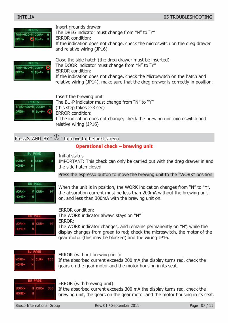
Insert grounds drawerInsert grounds drawerThe DREG indicator must change from “N” to “Y”The DREG indicator must change from “N” to “Y”ERROR condition:ERROR condition:If the indication does not change, check the microswitch on the dreg drawer If the indication does not change, check the microswitch on the dreg drawer and relative wiring (JP16).and relative wiring (JP16).
Close the side hatch (the dreg drawer must be inserted)Close the side hatch (the dreg drawer must be inserted)The DOOR indicator must change from “N” to “Y”The DOOR indicator must change from “N” to “Y”ERROR condition:ERROR condition:If the indication does not change, check the Microswitch on the hatch and If the indication does not change, check the Microswitch on the hatch and relative wiring (JP14), make sure that the dreg drawer is correctly in position.relative wiring (JP14), make sure that the dreg drawer is correctly in position.
Insert the brewing unitInsert the brewing unitThe BU-P indicator must change from “N” to “Y” The BU-P indicator must change from “N” to “Y” (this step takes 2-3 sec)(this step takes 2-3 sec)ERROR condition:If the indication does not change, check the brewing unit microswitch and relative wiring (JP16)
07
When the unit is in position, the WORK indication changes from “N” to “Y”, When the unit is in position, the WORK indication changes from “N” to “Y”, the absorption current must be less than 200mA without the brewing unit the absorption current must be less than 200mA without the brewing unit on, and less than 300mA with the brewing unit on.on, and less than 300mA with the brewing unit on.
ERROR condition:ERROR condition:The WORK indicator always stays on “N”The WORK indicator always stays on “N”ERROR:ERROR:The WORK indicator changes, and remains permanently on “N”, while the The WORK indicator changes, and remains permanently on “N”, while the display changes from green to red; check the microswitch, the motor of the display changes from green to red; check the microswitch, the motor of the gear motor (this may be blocked) and the wiring JP16.gear motor (this may be blocked) and the wiring JP16.
ERROR (without brewing unit):ERROR (without brewing unit):If the absorbed current exceeds 200 mA the display turns red, check the If the absorbed current exceeds 200 mA the display turns red, check the gears on the gear motor and the motor housing in its seat.gears on the gear motor and the motor housing in its seat.
Initial statusInitial statusIMPORTANT: This check can only be carried out with the dreg drawer in and IMPORTANT: This check can only be carried out with the dreg drawer in and the side hatch closedthe side hatch closed
Press the espresso button to move the brewing unit to the “WORK” position
Operational check – brewing unit
Press STAND_BY “ Press STAND_BY “ ” to move to the next screen ” to move to the next screen
ERROR (with brewing unit):ERROR (with brewing unit):If the absorbed current exceeds 300 mA the display turns red, check the If the absorbed current exceeds 300 mA the display turns red, check the brewing unit, the gears on the gear motor and the motor housing in its seat.brewing unit, the gears on the gear motor and the motor housing in its seat.
INTELIA 05 TROUBLESHOOTING
Saeco International Group Rev. 01 / September 2011 Page / 1108
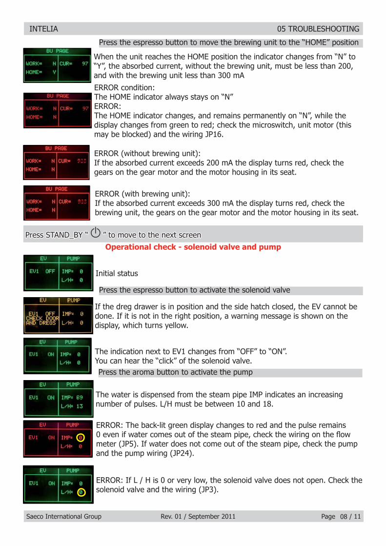
When the unit reaches the HOME position the indicator changes from “N” to When the unit reaches the HOME position the indicator changes from “N” to “Y”, the absorbed current, without the brewing unit, must be less than 200, “Y”, the absorbed current, without the brewing unit, must be less than 200, and with the brewing unit less than 300 mA and with the brewing unit less than 300 mA
ERROR condition:ERROR condition:The HOME indicator always stays on “N”The HOME indicator always stays on “N”ERROR:ERROR:The HOME indicator changes, and remains permanently on “N”, while the The HOME indicator changes, and remains permanently on “N”, while the display changes from green to red; check the microswitch, unit motor (this display changes from green to red; check the microswitch, unit motor (this may be blocked) and the wiring JP16.may be blocked) and the wiring JP16.
ERROR (without brewing unit):ERROR (without brewing unit):If the absorbed current exceeds 200 mA the display turns red, check the If the absorbed current exceeds 200 mA the display turns red, check the gears on the gear motor and the motor housing in its seat.gears on the gear motor and the motor housing in its seat.
Initial statusInitial status
Press the espresso button to activate the solenoid valve
Press the aroma button to activate the pump
Press the espresso button to move the brewing unit to the “HOME” position
Operational check - solenoid valve and pump
ERROR (with brewing unit):ERROR (with brewing unit):If the absorbed current exceeds 300 mA the display turns red, check the If the absorbed current exceeds 300 mA the display turns red, check the brewing unit, the gears on the gear motor and the motor housing in its seat.brewing unit, the gears on the gear motor and the motor housing in its seat.
If the dreg drawer is in position and the side hatch closed, the EV cannot be If the dreg drawer is in position and the side hatch closed, the EV cannot be done. If it is not in the right position, a warning message is shown on the done. If it is not in the right position, a warning message is shown on the display, which turns yellow.display, which turns yellow.
The indication next to EV1 changes from “OFF” to “ON”.The indication next to EV1 changes from “OFF” to “ON”.You can hear the “click” of the solenoid valve.You can hear the “click” of the solenoid valve.
The water is dispensed from the steam pipe IMP indicates an increasing The water is dispensed from the steam pipe IMP indicates an increasing number of pulses. L/H must be between 10 and 18.number of pulses. L/H must be between 10 and 18.
ERROR: The back-lit green display changes to red and the pulse remains ERROR: The back-lit green display changes to red and the pulse remains 0 even if water comes out of the steam pipe, check the wiring on the fl ow 0 even if water comes out of the steam pipe, check the wiring on the fl ow meter (JP5). If water does not come out of the steam pipe, check the pump meter (JP5). If water does not come out of the steam pipe, check the pump and the pump wiring (JP24).and the pump wiring (JP24).
Press STAND_BY “ Press STAND_BY “ ” to move to the next screen ” to move to the next screen
ERROR: If L / H is 0 or very low, the solenoid valve does not open. Check the ERROR: If L / H is 0 or very low, the solenoid valve does not open. Check the solenoid valve and the wiring (JP3).solenoid valve and the wiring (JP3).

INTELIA 05 TROUBLESHOOTING
Saeco International Group Rev. 01 / September 2011 Page / 1109
Operational check - coffee grinder and boiler
Initial StatusInitial Status
Press STAND_BY “ Press STAND_BY “ ” to move to the next screen ” to move to the next screen
Press the aroma button to activate the coffee grinder
Temperature control
Press the espresso button to activate the boiler
The coffee grinder starts to spin and the number of pulses is indicated by the The coffee grinder starts to spin and the number of pulses is indicated by the number circled in red, the other numbers have no signifi cance for this test.number circled in red, the other numbers have no signifi cance for this test.
ERROR:ERROR:If the number remains 0, the display changes to red, and the motor runs, the If the number remains 0, the display changes to red, and the motor runs, the problem lies in the Hall sensors, or their wiring, or in the CPU/POWER input problem lies in the Hall sensors, or their wiring, or in the CPU/POWER input (JP2). If the motor does not run, the problem may lie in the chain (JP8), the (JP2). If the motor does not run, the problem may lie in the chain (JP8), the coffee grinder wiring or the actual coffee grinder.coffee grinder wiring or the actual coffee grinder.
The circled number expresses the boiler temperature in degrees centigrade.The circled number expresses the boiler temperature in degrees centigrade.
ERROR:ERROR:If the HEATER indicator shows the word “SHORT”, this means that the NTC If the HEATER indicator shows the word “SHORT”, this means that the NTC temperature sensor is in short circuit. The display changes from green to red: temperature sensor is in short circuit. The display changes from green to red: in this case check the wiring on the NTC or the CPU/POWER inlet (JP13).in this case check the wiring on the NTC or the CPU/POWER inlet (JP13).
ERROR:ERROR:If the HEATER indicator displays the word “OPEN”, this means that the NTC If the HEATER indicator displays the word “OPEN”, this means that the NTC temperature sensor is disconnected; the display changes from green to red; temperature sensor is disconnected; the display changes from green to red; in this case check the continuity of the NTC wiring, and check the connection in this case check the continuity of the NTC wiring, and check the connection to the CPU/POWER in (JP13). to the CPU/POWER in (JP13).
The indicator changes from “OFF” to “ON” and shortly after the temperature The indicator changes from “OFF” to “ON” and shortly after the temperature indicator should start to increase, and the ammeter on the counter must dis-indicator should start to increase, and the ammeter on the counter must dis-play an absorption of approximately 8 Ampere with 230 volt. play an absorption of approximately 8 Ampere with 230 volt.
There is a further check to carry out if the temperature goes above 125°C There is a further check to carry out if the temperature goes above 125°C then the display changes to yellow and an alarm message appears on the then the display changes to yellow and an alarm message appears on the display. Above this temperature the boiler is always off, avoiding the risk of display. Above this temperature the boiler is always off, avoiding the risk of dangerously high temperatures.dangerously high temperatures.
ERROR:ERROR:If the temperature is not absorbed check the boiler resistor, relative wiring If the temperature is not absorbed check the boiler resistor, relative wiring and the connection to the CPU/POWER in (JP19), also check the wiring on the and the connection to the CPU/POWER in (JP19), also check the wiring on the NTC (JP13).NTC (JP13).

INTELIA 05 TROUBLESHOOTING
Saeco International Group Rev. 01 / September 2011 Page / 11
5.2. SteamOut
This procedure is carried out whenever you need to completely empty the residual water from This procedure is carried out whenever you need to completely empty the residual water from the boiler. the boiler. It is recommended to carry out the SteamOut when the machine is used in places It is recommended to carry out the SteamOut when the machine is used in places where the temperature could freeze the water inside the machinewhere the temperature could freeze the water inside the machine
When the machine is switched on the procedure starts; the display changes When the machine is switched on the procedure starts; the display changes to yellow and the word “ON” indicates that the procedure is running.to yellow and the word “ON” indicates that the procedure is running.During the procedure the 2-way solenoid valve remains open and the During the procedure the 2-way solenoid valve remains open and the steam is discharged.steam is discharged.
Caution!!!Caution!!!If the dreg drawer is not fully in, the machine will ask you to insert it, this If the dreg drawer is not fully in, the machine will ask you to insert it, this must be done otherwise the 2- and 3-way solenoid valves are not powered.must be done otherwise the 2- and 3-way solenoid valves are not powered.
Caution!!!Caution!!!If the side hatch opens, the machine warns you to close it, the hatch must If the side hatch opens, the machine warns you to close it, the hatch must be closed otherwise the 2- and 3-way solenoid valves will not be powered.be closed otherwise the 2- and 3-way solenoid valves will not be powered.
When the procedure is completed, the message “COMPLETE” appears on When the procedure is completed, the message “COMPLETE” appears on the display, the solenoid valves close automatically and the machine may the display, the solenoid valves close automatically and the machine may be switched off. be switched off.
To enter Test Mode Hold down the Espresso and 1. Menu buttons Switch on the main switch at 2. the back of the machine 1
2
10

INTELIA 05 TROUBLESHOOTING
Saeco International Group Rev. 01 / September 2011 Page / 11
ERROR ERROR CODESCODES DESCRIPTIONDESCRIPTION
0101 The coffee grinder is blocked (grinder blades jammed or sensor not reading properly)
0303The brewing unit is blocked in work position (microswitch not released in up position after 3", torque error trying to move down, descent time out exceeded)
0404The brewing unit is blocked in home position (microswitch not released in down position after 3", torque error trying to move up, ascent time out exceeded)
0505 Water circuit / fl ow meter problems (water circuit blocked or no fl ow meter signal)
1010 Boiler temperature sensor short circuited
1111 Boiler temperature sensor open circuit
1414 The boiler temperature has exceeded the maximum allowed value (165°c)
1515The boiler temperature has not increased by x°C in y sec (boiler power supply disconnected, incorrect boiler fi tted must be a 1300W boiler, par-tial power supply to boiler, cut out thermostat tripped)
1919 Mains voltage trouble
5.3. Error codes
11

Saeco International Group Rev. 01 / September 2011 INTELIA
CHAPTER 6 STANDARD CHECKS

INTELIA 06 STANDARD CHECKS
Saeco International Group Rev. 01 / September 2011 Page / 0201
Action1 Visual inspection (transport damage)2 Machine data check (rating plate)3 Operational check / problem analysis4 Opening machine5 Visual inspection6 Operational tests7 Repairing the faults encountered8 Checking any modifi cations (view Symptom Cure, new software, etc.)9 Service activities in accordance with the operating schedule
10 Internal cleaning11 Operational test while the appliance is open12 Assembly13 Final inspection test14 Draining the circuit (in winter)15 External cleaning16 Lubricating the brewing unit with suitable grease17 Insulation test HG 701 (dielectric)18 Documentation
S Replacement P CleaningES Visual inspection TR Noise testD Descaling R Adjustment
Component Action Support/toolWater fi lter P/SWater tank lip seal SBoiler pin O-ring SBrewing unit ES/P Grease solvent / GreaseHoses, attachments and Oetiker clamps ESPump ES/TRGear motor ES/TRCoffee grinder P/R Vacuum cleaner / brushWater circuit D Saeco descalerHot water/steam valve ES/S
6.2. Service schedule
6.1. Repair schedule

INTELIA 06 STANDARD CHECKS
Saeco International Group Rev. 01 / September 2011 Page / 0202
Test Procedure Support/tool Standard Tolerance
Espresso 2-3 Espressos for adjustment purposes
Measuring scoop Same amount 15%
Coffee 2-3 Coffees for adjustment purposes
Measuring scoop Same amount 15%
Noise Standard
Amount of cream
Blow into the cup until the cream separates
The cream should come together again to form a complete layer
Cream colour Hazel brown
Temperature Reading taken while dispensing Thermometer 84 ˚C ± 4 ˚C
Grinding level Check the grain size of the ground coffee
Hot water Dispense waterSteam Dispense steamDreg drawer missing indication
Remove the dreg drawer Dreg drawer missing indication
Low bean level indication
Start brewing a coffee while the coffee bean hopper is empty
Low bean level indication
6.3. Final test
Saeco International Group Rev. 01 / September 2011 INTELIA
CHAPTER 7 DISASSEMBLY

INTELIA 07 DISASSEMBLY
Saeco International Group Rev. 01 / September 2011 Page / 11
7.1. Intelia Cappuccino outer Shell
Remove the water tank, coffee con-tainer cover, drip tray, dreg drawer, brewing unit, carafe or hot water dispenser.
Unscrew the screws shown and remove the fi nger protection.
Lift the top cover. Unscrew the screws shown and slide out the left side body.
Loosen the screws as illustrated, slide out the rear body and the sound insulating cover of the coffee grinder.
01
Slide out the hatch.

INTELIA 07 DISASSEMBLY
Saeco International Group Rev. 01 / September 2011 Page / 11
7.2. Intellia Class and Focus outer Shell
Remove the water tank, coffee con-tainer cover, drip tray, dreg drawer, brewing unit, cappuccino maker or pannarello.
Unscrew the marked screws and remove the fi nger protection.
Raise the top cover.
Loosen the screws as illustrated and remove the left side body.
Loosen the screws as illustrated, slide out the rear body and the sound insulating cover of the coffee grinder.
7.3. Coffee grinder
Loosen the screws as illustrated and remove the sound insulating cover. Raise the coffee grinder and remove the connections.
When reassembling the coffee grinder, make sure the spring is repositioned correctly (see photo).
Slide out the hatch.
02

INTELIA 07 DISASSEMBLY
Saeco International Group Rev. 01 / September 2011 Page / 1103
To extract the top support of the appliance, press on the grinding adjustment spindle (A) and turn the support anticlockwise until it unhooks.
Turn the grinder blades anticlockwise out of the support.
Turn the grinder blades clockwise out of the support. The bayonet connections can be accessed from the rear.
For a standard adjustment, both markings must be aligned.
7.4. Grinder blades
A
B

INTELIA 07 DISASSEMBLY
Saeco International Group Rev. 01 / September 2011 Page / 1104
The grinding adjustment can be set by the user (only with the coffee grinder in operation) by pressing and turning (only by one click at a time) the insert inside the coffee bean hopper with the aid of the wrench supplied.
1) Loosen the screws holding the front plate to the upper plate2) Remove the front plate, pressing it in the center and pulling the side walls outward3) Remove the board support assembly4) Loosen the screws holding the solenoid valve to the upper plate5) Disconnect all electrical and water circuit connections
Adjustment by a service center
7.5. Coffee grinder adjustment
7.6. Intelia Cappuccino three-way solenoid valve
+
-
+
-
C
12
3
4 4 5
To adjust grinding further, the engineer can work directly on the coffee grinder by pressing and turning the ring nut (C) shown. (clockwise + to increase the particle size of the coffee and anticlockwise - to decrease it).
If there are any remains of coffee powder between the two grinding blades it is recommended to tighten by max. two marks at a time.
Lastly, move the arrow (A) on the adjustment knob to the center of the adjustment dots on the cover (B).

INTELIA 07 DISASSEMBLY
Saeco International Group Rev. 01 / September 2011 Page / 11
1) Loosen the screws holding the front plate to the upper plate.2) Remove the card support assembly.3) Loosen the screws holding the solenoid valve to the upper plate.4) Disconnect all electrical and water circuit connections.
7.7. Intelia Class and Focus two-way solenoid valve
2
3
4
1
1) Loosen the screws holding the front cover of the carafe fi tting body and release it from its seat2) Loosen the screws as illustrated3) Remove carafe presence sensors4) Remove carafe fi tting Tefl on pipe
7.8. Intelia Cappuccino carafe fi tting body
05
1
3
22 2
3 3 4

INTELIA 07 DISASSEMBLY
Saeco International Group Rev. 01 / September 2011 Page / 11
7.9. Pump
7.10. Flow-meter
Lift the fl ow meter out of the casing assembly and remove the electrical and water circuit connections.
Loosen the screws as illustrated, slide out the electrical connection and remove the card guard.
Slide the card off the support and disconnect the electrical connections.
Disconnect the water circuit connections (A) and electrical connections (B), loosen the safety valve (C) and slide the pump off the brackets (D).
06
7.11. Control board
A
B
D
D
CA
A
7.12. Water sensor control board
Slide the card off the support.
Slide out the pipe connecting the fl ow meter to the pump.
Loosen the screw as illustrated and remove the capacitive sensor glued to the seat.

INTELIA 07 DISASSEMBLY
Saeco International Group Rev. 01 / September 2011 Page / 11
7.13. Gear motor
Only for Intelia Cappuccino remove the plug body along with pitcher
Unscrew the screws (highlighted) and release the milk jug plug body assembly
Unscrew the screws in the front cover and lift it off the milk jug plug body from the place
07
Unscrew the screws as illustrated and remove the front panel to access the screws which fi x the dispenser cover into place.
Slide out the fork as illustrated.
Unscrew the screws shown and remove the fi nger protection.
Lift the top cover. Unscrew the screws shown and slide out the left side body.
INTELIA 07 DISASSEMBLY
Saeco International Group Rev. 01 / September 2011 Page / 1108
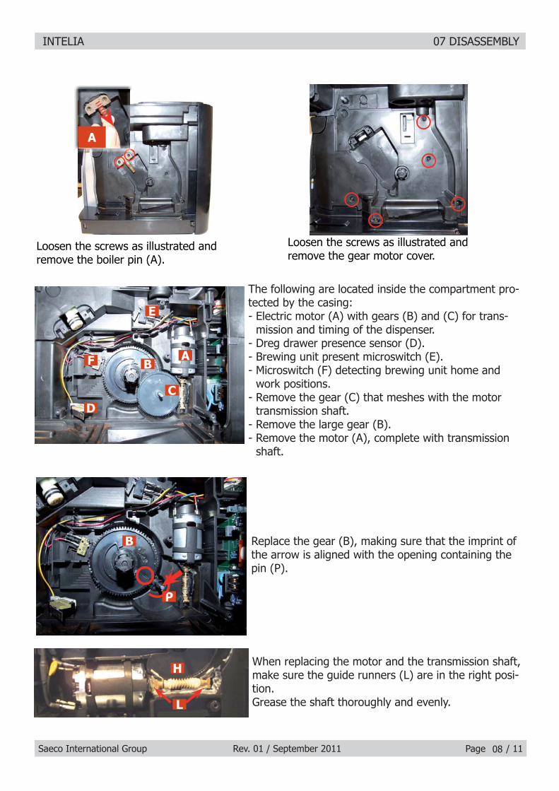
Loosen the screws as illustrated and remove the gear motor cover.
The following are located inside the compartment pro-tected by the casing:- Electric motor (A) with gears (B) and (C) for trans-
mission and timing of the dispenser.- Dreg drawer presence sensor (D).- Brewing unit present microswitch (E).- Microswitch (F) detecting brewing unit home and
work positions.- Remove the gear (C) that meshes with the motor
transmission shaft.- Remove the large gear (B).- Remove the motor (A), complete with transmission
shaft.
Loosen the screws as illustrated and remove the boiler pin (A).
Replace the gear (B), making sure that the imprint of the arrow is aligned with the opening containing the pin (P).
When replacing the motor and the transmission shaft, make sure the guide runners (L) are in the right posi-tion.Grease the shaft thoroughly and evenly.
AB
D
E
F
C
H
L
B
P
A

INTELIA 07 DISASSEMBLY
Saeco International Group Rev. 01 / September 2011 Page / 1109
7.15. Dispenser assembly
7.16. Valve disassembly
7.14. Boiler
Unscrew the marked screw and disconnect the electrical and water circuit connections.
Loosen the screws as illustrated and remove the front panel to access the screws which fi x the dispenser cover into place.
Press the hooks as illustrated and slide out the dispenser assembly.
Slide out the fork as illustrated.
Release the boiler cover and take it off.
Loosen the screws as illustrated and remove the front panel to access the screws which fi x the dispenser cover into place
Loosen the screws as illustrated and remove the boiler pin (A)
A

INTELIA 07 DISASSEMBLY
Saeco International Group Rev. 01 / September 2011 Page / 11
7.17. Control board and display
Loosen the screws as illustrated and remove the front panel.
Disconnect the electrical connections and unhook the card support.
Loosen the screws as illustrated.
Remove the frame from the keypad and the display.
Remove the electrical connections between the card and the display and release the card from the support.
Loosen the screws as illustrated.
10
Loosen the screws as illustrated and release the insert in the bottom of the body to obtain easy access for valve disassembly
Loosen the screws as illustrated, remove the hydraulic connections and take out the valve

INTELIA 07 DISASSEMBLY
Saeco International Group Rev. 01 / September 2011 Page / 11
Use a suitable pair of pliers to remove the clamp (as illustrated).
Tighten the clamp as illustrated.
1) Boiler connection.
2) Other connections.
7.18. Fitting and removing Oetiker clamps
11

Saeco International Group Rev. 01 / September 2011 INTELIA
CHAPTER 8 NOTES

INTELIA 08 NOTES
Saeco International Group Rev. 01 / September 2011 Page / 0101

Saeco International Group Rev. 01 / September 2011 INTELIA
CHAPTER 9 WATER CIRCUIT DIAGRAM

INTELIA 09 WATER CIRCUIT DIAGRAM
Saeco International Group Rev. 01 / September 2011 Page / 0101
Flow
met
erTu
rbin
a
Wat
er t
ank
Serb
atoi
o ac
qua
Silic
one
tube
Tubo
sili
cone
Si
licon
e tu
beTu
bo s
ilico
ne
Silic
one
tube
Tubo
sili
cone
Silic
one
tube
Tubo
sili
cone
Assy
Sol
enoi
d va
lve
Assi
eme
Elet
trov
alvo
le
4 ba
r Va
lve
Valv
ola
4 ba
r
Wat
er d
rain
Scar
ico
acqu
a
Wat
er d
rain
Scar
ico
acqu
a
Pum
pPo
mpa
Boile
rCa
ldai
a
Jug
conn
ectio
n
Safe
ty v
alve
Valv
ola
di s
icur
ezza
Intelia Cappuccino
Silic
one
tube
Tubo
sili
cone
Silic
one
tube
Tubo
sili
cone
Tefl o
n tu
beTu
bo T
efl o
n
Silic
one
tube
Tubo
sili
cone
Silic
one
tube
Tubo
sili
cone
Silic
one
tube
Tubo
sili
cone
Brew
uni
t G
rupp
o ca
ffè
Boile
r pi
nPe
rno
cald
aia

INTELIA 09 WATER CIRCUIT DIAGRAM
Saeco International Group Rev. 01 / September 2011 Page / 0102
Flow
met
erTu
rbin
a
Wat
er t
ank
Serb
atoi
o ac
qua
Silic
one
tube
Tubo
sili
cone
Silic
one
tube
Tubo
sili
cone
Silic
one
tube
Tubo
sili
cone
Silic
one
tube
Tubo
sili
cone
Silic
one
tube
Tubo
sili
cone
Silic
one
tube
Tubo
sili
cone
2
way
Sol
enoi
d va
lve
Elet
trov
alvo
la a
due
vie
Silic
one
tube
Tubo
sili
cone
4 ba
r Va
lve
Valv
ola
4 ba
r
Wat
er d
rain
Scar
ico
acqu
a
Boile
r pi
nPe
rno
cald
aia
Brew
uni
t G
rupp
o ca
ffè
Pum
pPo
mpa
Boile
rCa
ldai
a
Stea
m p
ipe
Tubo
vap
ore
Safe
ty v
alve
Valv
ola
di s
icur
ezza
Intelia Focus and Class

Saeco International Group Rev. 01 / September 2011 INTELIA
CHAPTER 10 ELECTRICAL DIAGRAM

INTELIA 10 WIRING DIAGRAM
Saeco International Group Rev. 01 / September 2011 Page / 0101
Intelia Focus and Class