Embed Size (px)
Citation preview
Gas Well De-Liquification WorkshopDenver, Colorado
February 27 - March 1, 2006
Small Diameter Casing Plungers
Authors: David Gregg and Jose Luis MaccarioCompanies: Multi Products Co. & Casing S.A.
Feb. 27 - Mar. 1, 2006 2006 Gas Well De-Liquification Workshop Denver, Colorado
2
What Problems Are We Solving?
• Extend the economic life of wells.• Reduce the production costs of marginal wells.• Enable you to find a solution to your production
problems.• Enable you to access a low cost, effective method to
produce your gas well.
Feb. 27 - Mar. 1, 2006 2006 Gas Well De-Liquification Workshop Denver, Colorado
3
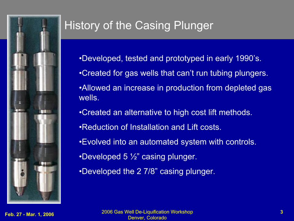
History of the Casing Plunger
•Developed, tested and prototyped in early 1990’s.
•Created for gas wells that can’t run tubing plungers.
•Allowed an increase in production from depleted gas wells.
•Created an alternative to high cost lift methods.
•Reduction of Installation and Lift costs.
•Evolved into an automated system with controls.
•Developed 5 ½” casing plunger.
•Developed the 2 7/8” casing plunger.
Feb. 27 - Mar. 1, 2006 2006 Gas Well De-Liquification Workshop Denver, Colorado
4
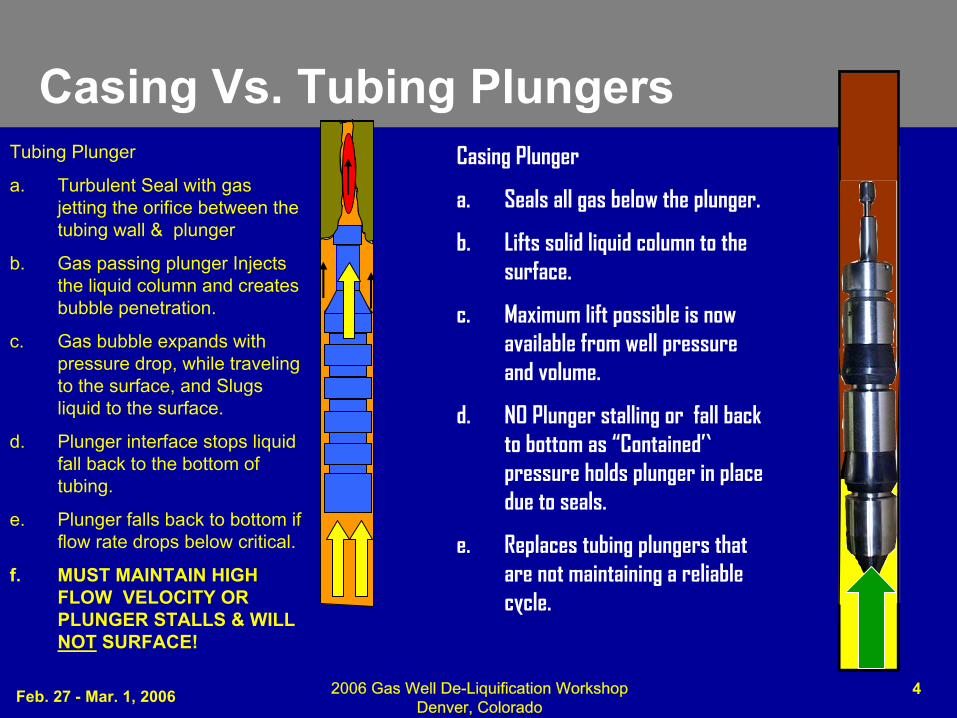
Tubing Plunger
a. Turbulent Seal with gas jetting the orifice between the tubing wall & plunger
b. Gas passing plunger Injects the liquid column and creates bubble penetration.
c. Gas bubble expands with pressure drop, while traveling to the surface, and Slugs liquid to the surface.
d. Plunger interface stops liquid fall back to the bottom of tubing.
e. Plunger falls back to bottom if flow rate drops below critical.
f. MUST MAINTAIN HIGH FLOW VELOCITY OR PLUNGER STALLS & WILL NOT SURFACE!
Casing Plunger
a. Seals all gas below the plunger.
b. Lifts solid liquid column to the surface.
c. Maximum lift possible is now available from well pressure and volume.
d. NO Plunger stalling or fall back to bottom as “Contained”pressure holds plunger in place due to seals.
e. Replaces tubing plungers that are not maintaining a reliable cycle.
Casing Vs. Tubing Plungers
Feb. 27 - Mar. 1, 2006 2006 Gas Well De-Liquification Workshop Denver, Colorado
5
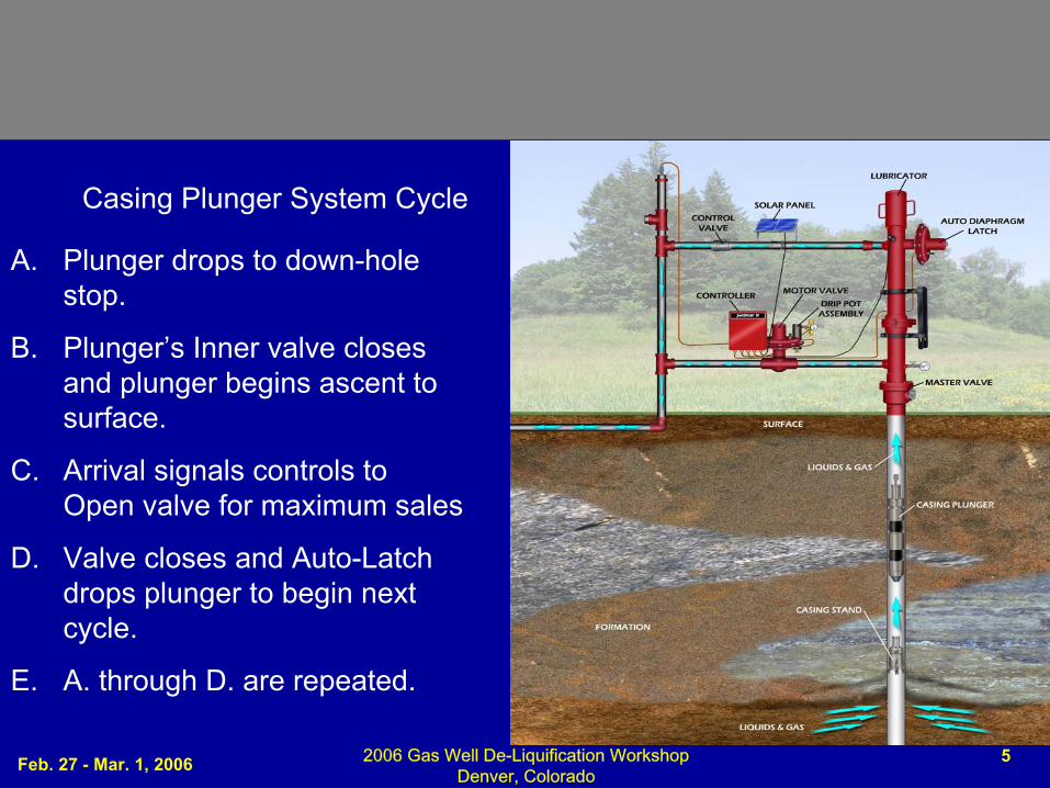
Casing Plunger System Cycle
A. Plunger drops to down-hole stop.
B. Plunger’s Inner valve closes and plunger begins ascent to surface.
C. Arrival signals controls to Open valve for maximum sales
D. Valve closes and Auto-Latch drops plunger to begin next cycle.
E. A. through D. are repeated.
Feb. 27 - Mar. 1, 2006 2006 Gas Well De-Liquification Workshop Denver, Colorado
6
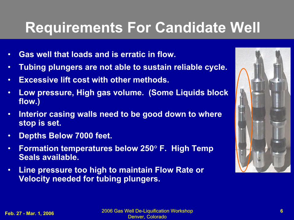
Requirements For Candidate Well• Gas well that loads and is erratic in flow.• Tubing plungers are not able to sustain reliable cycle. • Excessive lift cost with other methods. • Low pressure, High gas volume. (Some Liquids block
flow.)• Interior casing walls need to be good down to where
stop is set.• Depths Below 7000 feet.• Formation temperatures below 250° F. High Temp
Seals available.• Line pressure too high to maintain Flow Rate or
Velocity needed for tubing plungers.
Feb. 27 - Mar. 1, 2006 2006 Gas Well De-Liquification Workshop Denver, Colorado
7
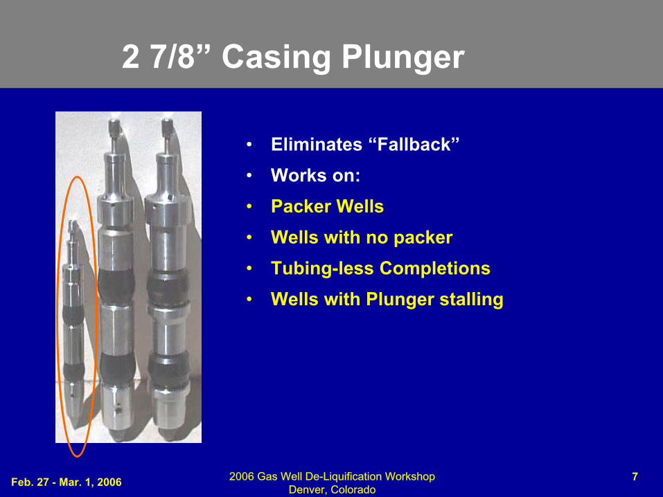
2 7/8” Casing Plunger
• Eliminates “Fallback”• Works on:• Packer Wells• Wells with no packer• Tubing-less Completions• Wells with Plunger stalling
Feb. 27 - Mar. 1, 2006 2006 Gas Well De-Liquification Workshop Denver, Colorado
8
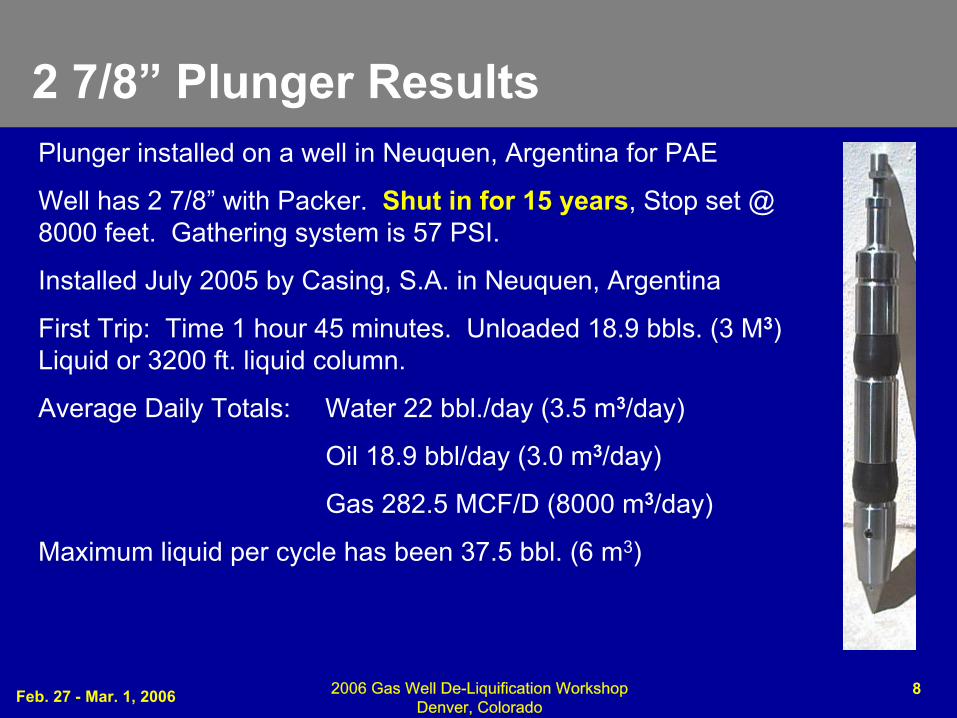
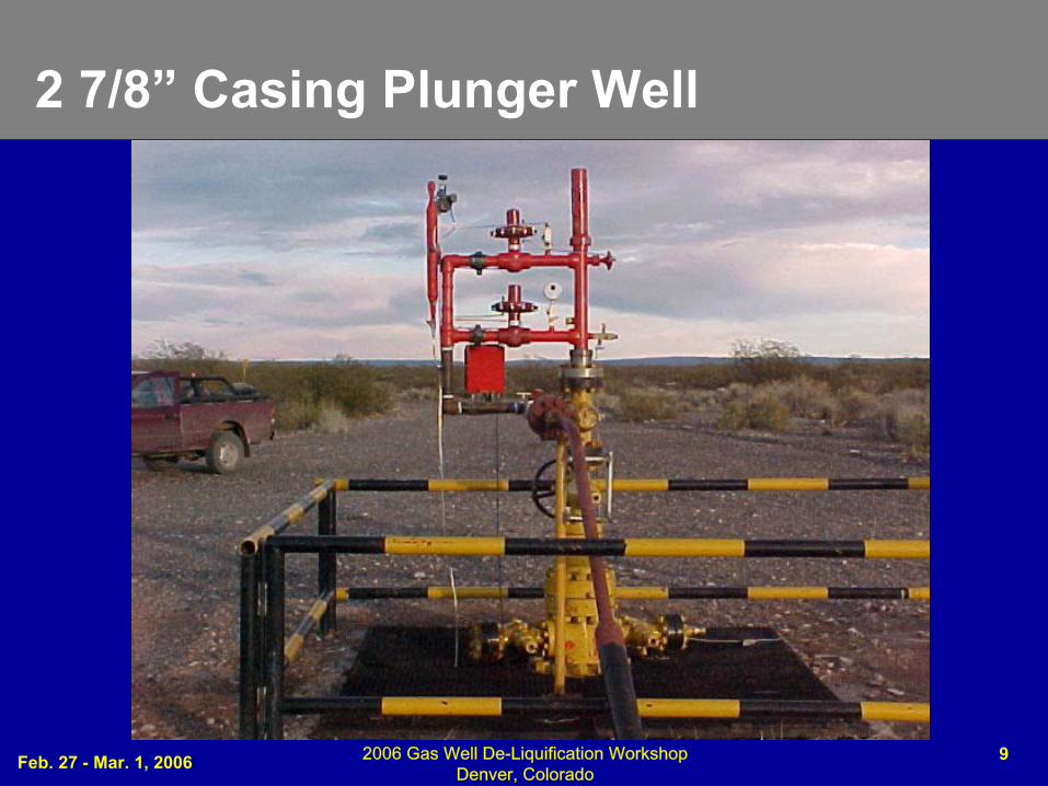
2 7/8” Plunger ResultsPlunger installed on a well in Neuquen, Argentina for PAE
Well has 2 7/8” with Packer. Shut in for 15 years, Stop set @ 8000 feet. Gathering system is 57 PSI.
Installed July 2005 by Casing, S.A. in Neuquen, Argentina
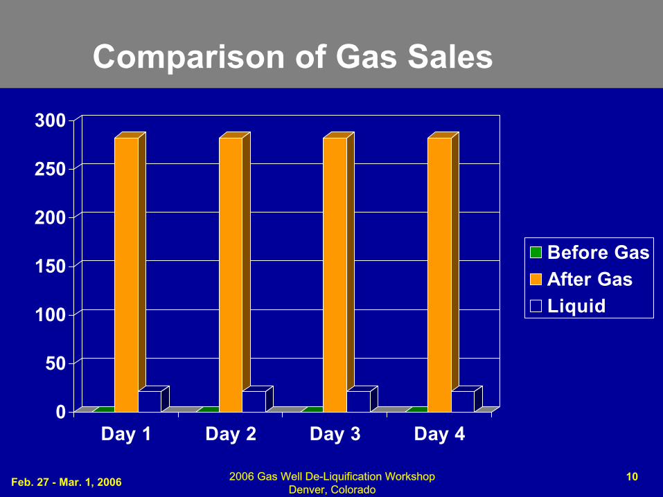
First Trip: Time 1 hour 45 minutes. Unloaded 18.9 bbls. (3 M3) Liquid or 3200 ft. liquid column.
Average Daily Totals: Water 22 bbl./day (3.5 m3/day)
Oil 18.9 bbl/day (3.0 m3/day)
Gas 282.5 MCF/D (8000 m3/day)
Maximum liquid per cycle has been 37.5 bbl. (6 m3)
Feb. 27 - Mar. 1, 2006 2006 Gas Well De-Liquification Workshop Denver, Colorado
9
2 7/8” Casing Plunger Well
Feb. 27 - Mar. 1, 2006 2006 Gas Well De-Liquification Workshop Denver, Colorado
10
Comparison of Gas Sales
0
50
100
150
200
250
300
Day 1 Day 2 Day 3 Day 4
Before GasAfter GasLiquid
Feb. 27 - Mar. 1, 2006 2006 Gas Well De-Liquification Workshop Denver, Colorado
11
Decision resulting From Installations
•Results are as good as any form of artificial lift can provide.
•Gas Volume increase provides short term payout of expenditure.
•Operating and Maintenance costs remain low for depleted well.
•Well now a source of revenue where not one prior to installation.
•Field personnel have less maintenance due to its self-sufficient operation.
•Original seals continue to work.
•Wax from the formation began to accumulate with a Hard film.
•System moved to another well due to deposition of film.
•Time on the well was 2 months due to hard film.
Feb. 27 - Mar. 1, 2006 2006 Gas Well De-Liquification Workshop Denver, Colorado
12
CONCLUSIONS
1. Most cost effective solution for marginal gas wells not able to maintain tubing plunger operation.
2. Production increases provide quick payback of investment.
3. Only system requirement is clean and smooth casing walls.
4. Stand-alone operation.
5. Removes liquid to maintain high well flow rates.
6. Works best on low pressure wells.
7. Provides revenue from Non-producing properties.