Embed Size (px)
Citation preview

AMSE JOURNALS-AMSE IIETA publication-2017-Series: Modelling D; Vol. 38; N°1; pp 102-110
Submitted April 2017; Revised July 30, 2017, Accepted Nov.15, 2017
Smart Glass for Blind People
*Ankita Bhuniya, **Sumanta Laha, ***Deb Kumar Maity, ****Abhishek Sarkar, *****Suvanjan
Bhattacharyya
* Department of ECE, MCKV Institute of Engineering, India
** Department of ME, MCKV Institute of Engineering, India
*** Department of ME, MCKV Institute of Engineering, India
**** Department of ECE, MCKV Institute of Engineering, India
***** Department of ME, MCKV Institute of Engineering, India ([email protected])
Abstract
Blind mobility is one of the major challenges encountered by visually impaired persons in
their daily lives. Their life and activities are greatly restricted by loss of eyesight. They normally
travel using blind navigation system or by their accumulated memories in their long term
exploration. The main objective of the present work is to develop a low cost, reliable, portable,
user friendly, low power and robust solution for smooth navigation.This paper (Smart Glasses for
Blind People), as meant are the glasses are for visually impaired people. It has an in-built sensor
in it which spreads ultrasonic waves in the direction the person is going by scanning at most 5-6
meters of 30º range. As soon as the obstacle is detected, the sensor detects it and sends it to the
device which generates an automated voice in the earphone connected to the person's ear.
Key words
Arduino, IVRS, microcontroller, ultrasonic, voice-assistant.
1. Introduction
On an approximation 285 million people are visually impaired across the globe, among
which 39 million are blind and 246 have low vision according to WHO statistics of 2011 [1].
About 90% of the world's visually impaired live in low-income settings whereas 82% of people
living with blindness are aged 50 and above. India is now home to the world's largest number of
102
blinds. Out of the 37 million blind people worldwide, over 15 million are from India. The worst
thing is that 75% of these are cases of avoidable blindness. India has an acute shortage of
optometrists and donated eyes for the treatment of corneal blindness. While India needs 40,000
optometrists, it has only 8,000. Blind people are usually dependent on assistance from others. The
assistance can be from human beings, dogs or some special electronic devices. There are already
many existing devices which help a blind person in walking. The most common is the simple
walking stick or cane. The blind man uses it to detect the obstacles by sweeping the cane back
and forth but unfortunately sometimes the blind man gets aware about the obstacle too late. With
the recent advances in technology normal walking cane has been modified to a blind stick with an
ultrasonic sensor attached to it. It has several limitations. Therefore, the solution that has been
protrayed in this paper is cost effective, reliable, robust and portable device which would help a
blind person to walk on the streets almost like any other pedestrian.
2. Literature Review
In a rapidly flourishing country like our innumerable number of attempts has been made for
the welfare of especially able people of our society. One of such attempts is the project “Project
Prakash"[2], an empathetic attempt towards the blind children to help them gain knowledge of a
set of obstacles around them by using their brains. Sheth et al [3] worked on how a blind people
can be able to detect any type of pits, potholes and several ups and downs by using a smart white
cane where they have used ultrasonic sensors. In this device a multilingual system for audio
feedback cannot be used because it can record only for 680 seconds. The idea that can be seen in
[4] has an ultrasonic sensor, a water sensor and a pit sensor. It also consists of a GPS system but
here the user needs to give the present location as the input itself. The method of doing so has not
been mentioned herein. In [5] it can be observed that it consists of a video camera on the frame
itself as well as a computer processing unit precise enough to get fit in the pocket and the
software that provides images of objects close by to transparent displays on the eyepieces. The
major limitation of this device is that it is not at all suitable for completely blind people. It is
recommended only for people with low vision or night blindness. There is another new attempt of
assisting the blind people which is named as H.A.L.O or Haptic Assisted Location of Obstacles
[6]. It consists of rangefinders that would take input from the ultrasonic sensors and output
feedback to pulse vibration motors which are placed on the blind man's head. When the person
gets closer to the object, the intensity and frequency of the vibration are increased. The main
limitation is the use of vibration motor. The vibrations as an output feedback are far way irritating
for any blind person.
103

3. Objective
The main objective of our present work is to provide a reliable, cost effective, low power
solution for a blind people which would help them to move almost like any other normal
pedestrian. The cost of this system makes it affordable for the majority of the society which in
turn an effective device for them to spend on, just for once and assures wonderful travel guidance
for them.
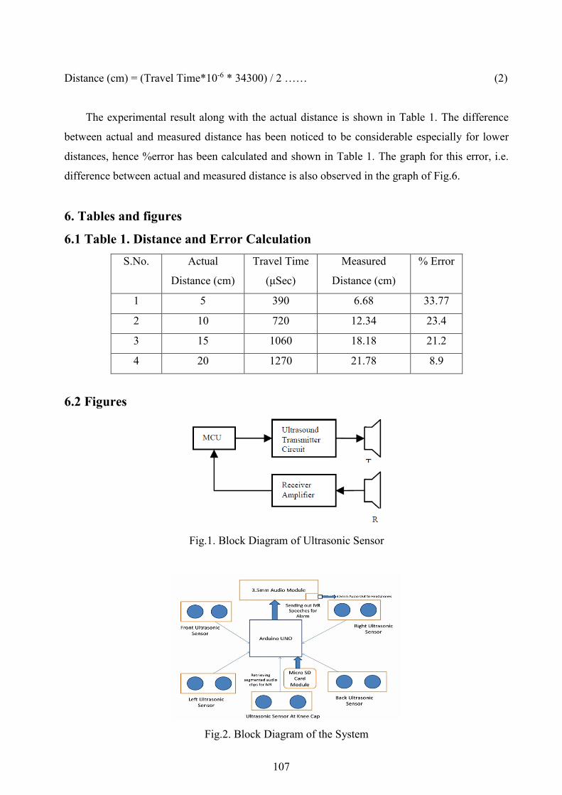
4. Working Principle
4.1 Ultrasonic Sensor
Ultrasonic Sensor is a transducer which uses the physical characteristics and various other
effects of ultrasound of a specific frequency which may transmit or receive the ultrasonic signal
of a particular strength. These are available in electromagnetic or piezoelectric versions. The
piezoelectric type is generally preferred due to its lower cost and simplicity to use comparatively
than other types [7].
The system mainly lies on the principle of Ultrasonic Range Finding sensor or simply an
ultrasonic sensor. It works on 40 KHz ultrasonic sound wave which when triggered by its
transmitter module, its receiver module receives back the echo of the triggered signal, having a
sensing angle of 30°. The block diagram of an ultrasonic sensor is shown below in Fig.1.
The propagation velocity of the ultrasonic wave is approximately 340m/s at 15°C of air or
atmospheric temperature. The ultrasound velocity depends by the propagation medium and its
temperature; hence the velocity in air is calculated using the equation 1, where t is the
temperature in °C.
V= 340+0.6(t-15) m/s ………. (1)
In this study, a room temperature of 20°C is assumed; hence the velocity of ultrasound in the
air is taken as 343 m/s. It is because the travel distance is very short; the travel time is little
affected by temperature. It takes approximately 29.15μsec for the ultrasound to propagate waves
through 1cm distance; hence it is possible to have 1cm resolution in the system [7].
4.2 IVR System
IVR System or Interactive Voice Response System which basically works on segmented
recorded voice clips to be logically merged and amended as per requirements. The SD Card
104
module is directly interfaced to the Arduino board to store the segmented voice clips of the IVR
system we built in different languages and is programmed on the Arduino board. The languages
can be changed over sequentially by two wire terminals kept open outside, when no command is
currently being played by the IVR, if the two wires are touched to each other for a moment, the
next language, as per the programmed sequence inside, will be played. Currently the system is
programmed for only English and Hindi, and many more languages will be added in near future.
4.3 Circuit Planning
The 5 ultrasonic sensors are well placed on the spectacle to sense 4 directions and one on the
knee cap for detecting smaller obstacles, block diagram shown in Fig.2.
It requires 5x4=20 pin-outs from Arduino to be interfaced with them. The terminals of a
sensor are as follows: 1. Vcc, 2. Trigger, 3. Echo, 4. Gnd, among which Vcc and Gnd can be
common to all 5 sensors and hence prevents wastage of GPIO pins of Arduino and to make room
for other components to be interfaced into the single board alongside the sensors. Other
components need to be interfaced are the SD card module which needs 6pins and the 3.5mm
Audio module (self-made) needs 3pins. Arduino has 13 Digital pins and 6 analog pins and among
which 20(5x4), 6, 3 pins are thus required for the complete interfacing of all three major
components and it is clear that pins will fall short, thus we kept shorted 5-6 pin-outs of Vcc &
Gnd (which are nothing but power source for the sensors) each in the self-made Audio module so
that only Trigger and Echo pin of each separate sensor needs to be directly interfaced to Arduino
and rest can be by-passed through the audio module itself. The Audio of the IVR system can be
received by a headphone through the self-made 3.5mm audio module which is basically filtering
the audio received in form PWM bits signal from the Arduino board.
4.4 Priority System of Working
The System works on priority to guide the blind man which can be readily changed as per
requirements. Currently set priorities are described below:
• If there is an obstacle within 80cm detected by the knee cap sensor then the person will be
alerted about it.
• If there is an obstacle detected by the front sensor within 120 cm then the person will be
directed to move left.
• If there is an obstacle detected by the left sensor within 100cm, along with the previous
point, then the person will be directed to move right.
105
• If now an obstacle detected by the right sensor within 100cm, along with the previous
point, then the person will be directed to step back.
• If now there is an obstacle detected by the sensor at the back within a range of 80cm,
along with the previous point, then the person will be alerted that it is a congested area and
system is unable to guide.
5. Experimental Results
First of all, this system is just a guidance system and it doesn’t do anything on its own but
just guides the blind person how to traverse. In no way does this system guarantee if a blind
person use this, he will be able to walk similar to a normal person because system needs time to
process the sensor values and guide them so they need to be walking at an appropriate speed so as
to allow the system to process and guide them, it won’t be similar to a normal person who can
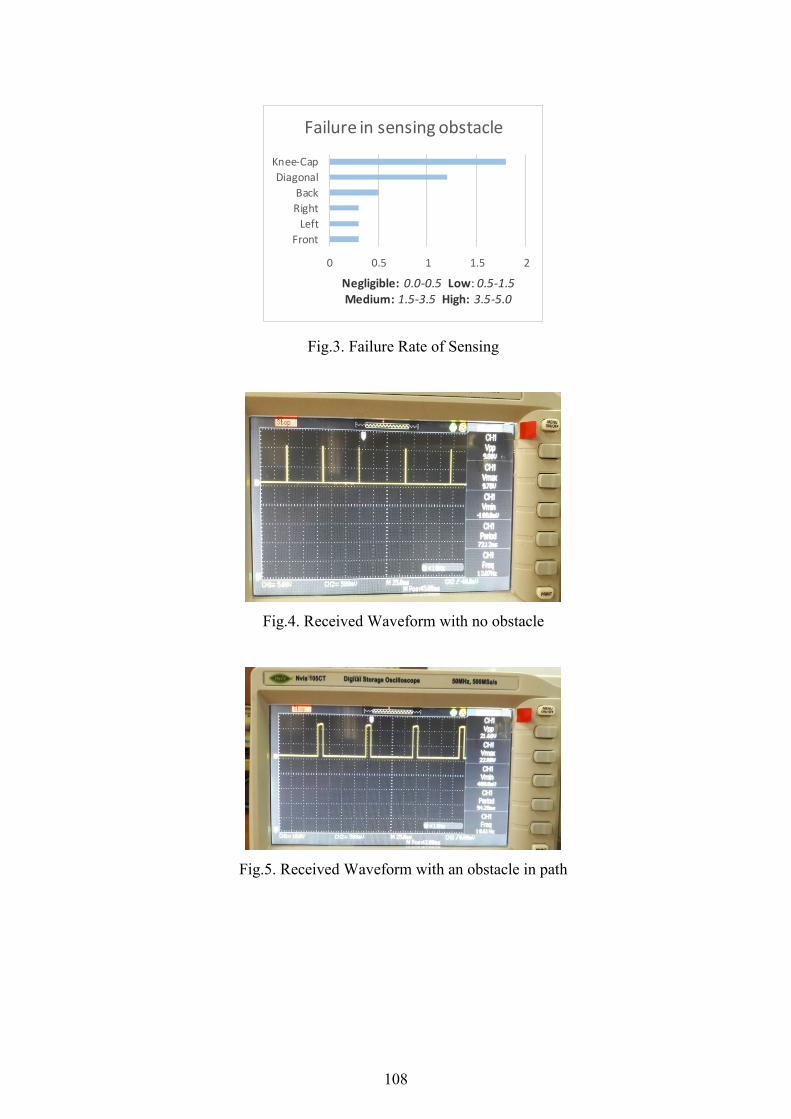
see. This system has been tested on 10 blind persons and some limitations and usage problems
has been traced. They are as follows:
(1) The sensor being highly directional, at times it may happen if there may be a
diagonally situated obstacle in between front and right sensor, the guidance frequently changes,
but it happens for a specific range and not always at every spot, 2-3 out of 10 people faced this
problem.
(2) If not placed appropriately, the knee cap sensor may overlook or may not sense
obstacles of 10-15cm height lying on the ground, which may be steps, speed breakers, etc. 3-4
out of 10 people faced this problem
(3) Front part and appropriate level of smaller obstacles for knee cap sensor worked
flawlessly most of the time.
(4) The blind man should normally be on its straight path, as per their feeling, unless
and until system guides them to turn in any direction, otherwise it was noticed that some kind of
avoidance of an obstacle may happen.
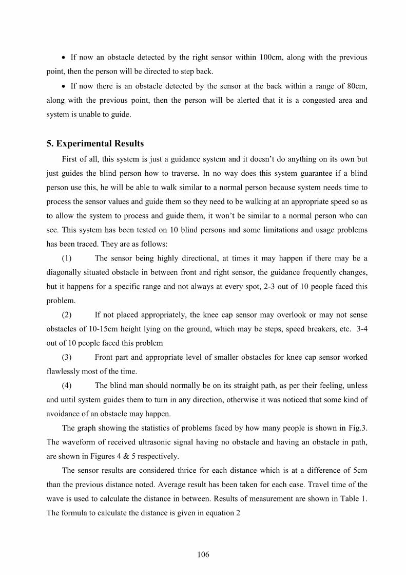
The graph showing the statistics of problems faced by how many people is shown in Fig.3.
The waveform of received ultrasonic signal having no obstacle and having an obstacle in path,
are shown in Figures 4 & 5 respectively.
The sensor results are considered thrice for each distance which is at a difference of 5cm
than the previous distance noted. Average result has been taken for each case. Travel time of the
wave is used to calculate the distance in between. Results of measurement are shown in Table 1.
The formula to calculate the distance is given in equation 2
106
Distance (cm) = (Travel Time*10-6 * 34300) / 2 …… (2)
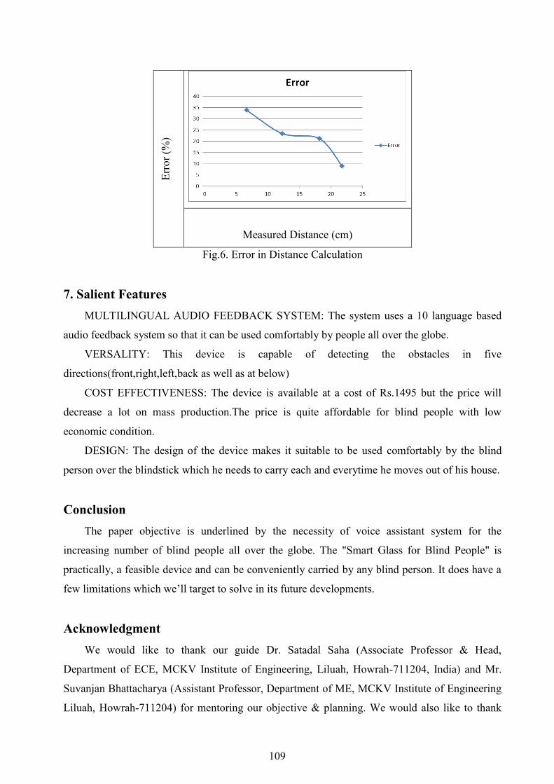
The experimental result along with the actual distance is shown in Table 1. The difference
between actual and measured distance has been noticed to be considerable especially for lower
distances, hence %error has been calculated and shown in Table 1. The graph for this error, i.e.
difference between actual and measured distance is also observed in the graph of Fig.6.
6. Tables and figures
6.1 Table 1. Distance and Error Calculation
S.No.
Actual
Distance (cm)
Travel Time
(μSec)
Measured
Distance (cm)
% Error
1 5 390 6.68 33.77
2 10 720 12.34 23.4
3 15 1060 18.18 21.2
4 20 1270 21.78 8.9
6.2 Figures
Fig.1. Block Diagram of Ultrasonic Sensor
Fig.2. Block Diagram of the System
107
0 0.5 1 1.5 2
Front
Left
Right
Back
Diagonal
Knee-Cap
Negligible: 0.0-0.5 Low: 0.5-1.5 Medium: 1.5-3.5 High: 3.5-5.0
Failure in sensing obstacle
Fig.3. Failure Rate of Sensing
Fig.4. Received Waveform with no obstacle
Fig.5. Received Waveform with an obstacle in path
108
Err
or
(%)
Measured Distance (cm)
Fig.6. Error in Distance Calculation
7. Salient Features
MULTILINGUAL AUDIO FEEDBACK SYSTEM: The system uses a 10 language based
audio feedback system so that it can be used comfortably by people all over the globe.
VERSALITY: This device is capable of detecting the obstacles in five
directions(front,right,left,back as well as at below)
COST EFFECTIVENESS: The device is available at a cost of Rs.1495 but the price will
decrease a lot on mass production.The price is quite affordable for blind people with low
economic condition.
DESIGN: The design of the device makes it suitable to be used comfortably by the blind
person over the blindstick which he needs to carry each and everytime he moves out of his house.
Conclusion
The paper objective is underlined by the necessity of voice assistant system for the
increasing number of blind people all over the globe. The "Smart Glass for Blind People" is
practically, a feasible device and can be conveniently carried by any blind person. It does have a
few limitations which we’ll target to solve in its future developments.
Acknowledgment
We would like to thank our guide Dr. Satadal Saha (Associate Professor & Head,
Department of ECE, MCKV Institute of Engineering, Liluah, Howrah-711204, India) and Mr.
Suvanjan Bhattacharya (Assistant Professor, Department of ME, MCKV Institute of Engineering
Liluah, Howrah-711204) for mentoring our objective & planning. We would also like to thank
109

Dr. Parasar Bandopadhyay (Director, MCKV Institute of Engineering) and Mr. Abir Shee
(Program Manager, Digital Business Service, SAP India) for constantly supporting us throughout
the project.
References
1. http://www.who.int/mediacentre/factsheets/fs282/en/
2. "Project Prakash" . https://nei.nih.gov/news/scienceadvances/discovery/project_prakash.
3. Rohit Sheth, Surabhi Rajandekar, Shalaka Laddha and Rahul Chaudhari (2014). American
Journal of Engineering. [Online]. 03(10), pp-84-89. Available:
http://www.ajer.org/papers/v3(10)/L031084089.pdf
4. G.Gayathri,M.Vishnupriya,R.Nandhini,Ms.M.Banupriya(2014, March). International
Journal of Engineering And Computer Science. [Online]. 03(03), pp-4057-4061. Available:
http://ijecs.in/issue/v3-i3/8%20ijecs. Pdf
5. Sarah Griffiths and Fiona Macrae. (2014, June). Smart glasses for the BLIND: Display turns
the world into outlines to help people with poor vision 'see' obstacles
andfaces.[Online].Available:http://www.dailymail.co.uk/sciencetech/article-2659993/Smart-
glasses-BLIND-Device-transforms-world-outlines-shapes-help-partially -sighted-
navigate.html
6. Steve (2010, Dec). HALO-Haptic Feedback System for Blind/Visually-Impaired. [Online].
Available: http:// www.polymythic.com/2010/12/teaser-haptic-feedback-for-visually-
impaired
7. K. Shrivastava, A. Verma, and S. P. Singh. Distance Measurement of an Object or Obstacle
by Ultrasound Sensors using P89C51RD2.(2010,February).International Journal of
Computer Theory and Engineering.[Online].02(01), pp-1793 - 8201. Available:
http://ijcte.org/papers/118-G227.pdf
110


![Indoor localization and navigation for blind persons using ... · Drishti [1] is an in- and outdoor navigation system. Outdoor it uses DGPS localization to keep the user as close](https://img.pdfslide.net/doc/110x75/5fe1ce25ab027730e458db70/indoor-localization-and-navigation-for-blind-persons-using-drishti-1-is-an.jpg)

![ASSIST: Personalized indoor navigation via multimodal ...openaccess.thecvf.com/content_ECCVW_2018/papers/... · lion blind & visually impaired (BVI) individuals worldwide [22] and](https://img.pdfslide.net/doc/110x75/5ec470c187b6177b0d6860a0/assist-personalized-indoor-navigation-via-multimodal-lion-blind-visually.jpg)