Embed Size (px)
Citation preview

Smart Professional Surveillance System User’s Manual
Version 1.0.0

i
Table of Contents
1 OVERVIEW AND ENVIRONMENT ..................................................................... 1
1.1 Overview ................................................................................................................................................. 1
1.2 Environment ........................................................................................................................................... 1
2 INSTALLATION AND UPGRADE ....................................................................... 2
2.1 Installation ............................................................................................................................................... 2
2.2 Un-installation ........................................................................................................................................ 5
3 SETUP ................................................................................................................ 7
3.1 Login Interface ....................................................................................................................................... 7
3.2 Main Interface ........................................................................................................................................ 7
3.3 Initialization Setup ................................................................................................................................. 8
3.3.1 User Manager .................................................................................................................................... 8
3.3.1.1 Add user ................................................................................................................................... 8
3.3.1.2 Modify or Delete Users ......................................................................................................... 10
3.3.2 General ............................................................................................................................................. 10
3.3.3 Device Manager .............................................................................................................................. 12
3.3.3.1 Add Device ............................................................................................................................. 12
3.3.3.2 Group Manager ...................................................................................................................... 14
3.4 Alarm Config ......................................................................................................................................... 16
3.4.1 Set Alarm Scheme .......................................................................................................................... 16
3.4.2 Alarm Activation Video ................................................................................................................... 19
3.4.3 Enable/Disable/Export Scheme .................................................................................................... 21
3.5 TV Wall Configuration ......................................................................................................................... 21

ii
3.6 Tour ....................................................................................................................................................... 23
3.7 PC-NVR ................................................................................................................................................ 25
4 BASIC OPERATION ......................................................................................... 30
4.1 Preview.................................................................................................................................................. 30
4.1.1 Real-time Preview ........................................................................................................................... 30
4.1.2 Record .............................................................................................................................................. 32
4.1.3 Snapshot .......................................................................................................................................... 32
4.1.4 PTZ ................................................................................................................................................... 33
4.1.4.1 Preset ...................................................................................................................................... 34
4.1.4.2 Tour ......................................................................................................................................... 34
4.2 Playback ................................................................................................................................................ 36
4.2.1 Playback Record ............................................................................................................................. 37
4.2.2 Record List ....................................................................................................................................... 38
4.3 Alarm Manager..................................................................................................................................... 40
4.4 Alarm Activation ................................................................................................................................... 41
4.5 TV Wall .................................................................................................................................................. 42
4.6 E-map .................................................................................................................................................... 43
4.6.1 Edit E-map ....................................................................................................................................... 43
4.6.2 Preview E-map ................................................................................................................................ 44
4.7 Device Display Control ....................................................................................................................... 44

iii
Welcome
Thank you for using our Smart Professional Surveillance System (Smart PSS)!
This user’s manual is designed to be a reference tool for operation of your system.
Here you can find detailed operation information about Smart PSS.

1
1 Overview and Environment
1.1 Overview
Smart PSS is an abbreviation for Smart Professional Surveillance System.
It is software to manage small quantity security surveillance devices. It releases with the device
and does not support the products from other manufacturers. It has the following features:
View real-time video of several camera channels.
View the playback video files from various cameras.
Support multiple scheduled arms to realize auto PC guard.
Support e-map; you can clearly view and manage all device locations.
TV wall plan setup and can output TV wall video at the same time.
Realize people counting, behavior analytics, facial recognition, intelligent track. It enters
intelligent time.
It can create individual configuration files for each user, which allows you maintain your own
habit and style.
Support extension applications, can send out alarm information to external programs.
1.2 Environment
Item Requirements
OS Windows 2000/Windows XP/Windows 2003/Window Vista/Win7.
CPU 2.4GHz or higher.
Display card Independent car and support directX 8.0c or higher.
Memory 1GB or higher for XP OS.
Displayer 1024×768 or higher.

2
2 Installation and Upgrade
2.1 Installation
1) Double click “SmartPSS_Setup.exe” to begin installation. See Figure 2-1.
Figure 2-1
2) Select installation language from the dropdown list and then click OK button to go to
Welcome interface. See Figure 2-2.
Figure 2-2
3) Click next button, you can see an interface is shown as in Figure 2-3. Here you can view
End user License Agreement.

3
Figure 2-3
4) Please check the Accept item and then click Next button to continue. System pops up
module installation dialogue box. See Figure 2-4.
Figure 2-4
5) Check Smart PSS item and then click Next button, you can see there is an interface asking
you to specify installation path. See Figure 2-5.
Note
You can check PC-NVR item if necessary.

4
Figure 2-5
6) After you select installation path click Next button, system begins installation. The interface
is shown as in Figure 2-6.
Figure 2-6
7) During the installation process, you can click Cancel button to exit. After installation, you can
see an interface is shown as below. See Figure 2-7.

5
Figure 2-7
8) Click Finish button, you can complete the installation.
2.2 Un-installation
1) From Start -> All programs->Smart PSS, select Uninstall Smart PSS item. System pops up
the following dialogue box. See Figure 2-8. Please click yes to remove PSS.
Figure 2-8
2) Click Next button, you can see an interface shown as in Figure 2-9.
3) Check the box here to remove Smart PSS. You can check the box to remove PC-NVR too.
Click Uninstall button to remove.

6
Figure 2-9

7
3 Setup
Double click Smart PSS icon , you can go to the login interface.
3.1 Login Interface
Login interface is shown as in Figure 3-1.
User name: Input the user account
Password: Please input corresponding password to log in.
OK: Click this button, system can verify the account and then enter the software main
interface.
Cancel: Click this button to exit login interface.
Note:
If it is your first time to run the Smart PSS program, default user name is admin and its
password is admin too. Admin is a super administrator and can not be removed. It can add,
modify or delete other user.
For security reason, please modify your password after first log in.
You can memory your password, so that when you can log in the next time, you do not need
to input user name and password. Please note this function is for your convenient only. Do
not enable this function in public PC.
Figure 3-1
3.2 Main Interface
Click Login button, system begins verifying user name and password and then go to the main
interface. See Figure 3-2.

8
Figure 3-2
Please refer to the following sheet for detailed information.
SN Parameter Function
1 Menu Here you can view main page icons and current open function icon.
2 Basic It includes preview, playback, alarm manager, alarm link, TV wall, e-map, device display control and etc.
3 Extension It includes behavior analytics, people counting, facial recognition, intelligent track and etc.
4 Setting It includes basic configuration, alarm configuration, TV wall configuration, device manager, user manager, PC-NVR manager, monitor task setup and etc.
5 Smart PSS basic information
It is to display current time, user information, login time.
3.3 Initialization Setup
3.3.1 User Manager
Here you can add, modify or delete a user.
3.3.1.1 Add user
1) Click in the Setting pane, you can go to the following interface. See Figure 3-3.

9
Figure 3-3
2) Click Add button, you can see system pops up the following interface. See Figure 3-4.
Figure 3-4
3) Select user type, input user name, password and confirm password. Input some description
information if necessary. Select rights for the new user.

10
4) Click add button to add a new user. Or you can click Add more button if you want to add
more new users.
Please refer to the following sheet for detailed information.
Item Function
User type You can select user type from the dropdown list. It includes: manager/operator.
User name Please input user name here.
Password Please set user password.
Confirm password
Please input new password again.
Details You can input some description information here if necessary,.
User authority
Here you can check the box to select corresponding rights for current user.
If the new user is a manager, system checks all rights by default.
Add more Check the box here if you want to add more users.
3.3.1.2 Modify or Delete Users
Select a user in the list, and then click to modify, or click to delete it. Or you can select
several users and then click the Delete button at the left bottom corner to remove them all.
3.3.2 General
Here you can set system network function, log save time, auto login Smart PSS /Windows or not,
picture/record save path.
Click the button; you can go to the basic setup interface. See Figure 3-5.

11
Figure 3-5
Please refer to the following sheet for detailed information.
Item Function
Network function
It is for you to set network function. It includes: “WAN”, “10M”,’100M’,”1000M”.
Log save period
Here you can set log save time. System automatically overwrites old files once it reaches the period you set here. It includes; 1/2/3/4/5/6-month.
Auto login Smart PSS
Check the box here, you can login Smart PSS directly without inputting user name and password.
Auto login Windows
Check the box here and then input user name and password, you can go to the Windows OS after the computer restart.
Auto sync time
Check the box here to enable time synchronization function and then input synchronization time. Smart PSS can auto synchronize time with the PC at the time you specified.
Default Click it to restore system default setup.
File configuration interface is shown as below. See Figure 3-6.
Here you can set snapshot picture and record file default save path.

12
Figure 3-6
3.3.3 Device Manager
Here you can add, modify and delete a device. You can also implement device channel group
function.
3.3.3.1 Add Device
You can refer to the steps listed below to add, modify or delete a device manually or
automatically.
3.3.3.1.1 Auto add
1) Click icon, system goes to the device manager interface; you can see an interface is
shown as in Figure 3-7.
Figure 3-7

13
2) Click Auto add button, you can see an interface shown as in Figure 3-8.
3) Please check the box to select the devices you want to add and then click the Add button.
Figure 3-8
3.3.3.1.2 Manual Add
Click Manual Add button, the interface is shown as in Figure 3-9. Please input the corresponding
information and then click Add button.
Figure 3-9

14
Please refer to the following sheet for detailed information.
Item Function
Title Please input a device name here.
Type Select a device type from the dropdown list.。
Add type Default type is to add one by one.
IP Device IP address. You need to select IP version first: IPv4 or IPv6.
Port Device IP port.
User name The user name you login the device.
Password The password you login the device.
Getting info It is to get the online device information automatically.
Device model
Device model. Read-only.
Device SN Device SN. Read-only.
Video input Device video input channel amount.
Video output Device video output channel amount.
Alarm input Device alarm input amount.
Alarm output Device alarm output amount.
Continuous add
Click it to add more devices.
3.3.3.1.3 Add/Modify Device
Select a device in the list, and then click to modify, or click to delete it. Or you can select
several devices and then click the Delete button at the left bottom corner to remove them all.
3.3.3.2 Group Manager
After you add devices, you can set channel group to manage it.
1) Right click the at the top right
pane on Figure 3-7, you can go to the following interface. See Figure 3-10.

15
Figure 3-10
2) Click the New group button at the right top corner, you can create new group.
Note
You can double click group name to change its name. Or you can right click a group
name to rename or delete it.
You can select a group and then click the button to delete it.
3) On the Device list on the left pane, you can select a device. You can view the corresponding
channel name on the near pane.
4) Select corresponding channels and then click , you can add channels to the new
group you created here. See Figure 3-11.
5) Click Finish button to complete the setup.

16
Figure 3-11
Note
For a device or a channel that is not included in the group management mode, you can not view
it on the device list of the Preview interface.
Tips
You can user Ctrl+channel ro select several channels at the same time. Or you can user Ctril+A
to select all channels.
3.4 Alarm Config
3.4.1 Set Alarm Scheme
You can follow the steps listed below to set an alarm scheme.
1) Click the icon , you can go to alarm configuration interface. See Figure 3-12.

17
Figure 3-12
2) Click Add button, you can set scheme information. See Figure 3-13.
Please refer to the following sheet for detailed information.
Item Function
Scheme name
Please input a scheme name here.
Memo You can input some description information here if necessary.
Time Input arm/disarm period and select corresponding level.
All-day: It is to arm the alarm scheme for a whole day.
Period: You can set different periods for each scheme. You
can use to add period, or you can use to delete period.
Note:
On period mode, the rest period here refers to the free periods you have not set.
Audio It is to set alarm sound.
Alarm type: It is to select alarm type you want to enable sound function.
Sound path: Select audio file path. You can click Browse button to select the audio file you want to use.
Loop play: Check the box here, system can play the audio repeatedly when a corresponding alarm occurs.
Play: Click it to hear current audio file.
Default: For non-customized alarm type, you can click this button to restore default setup.
Others Check the “E-map flash when an alarm occurs”, you can see the corresponding icon on the e-map flashes when an alarm occurs.

18
Figure 3-13
3) Set alarm source.
a) Click , system goes to alarm source setup interface. Or you can
click next button in Figure 3-13 to go to the following interface. See Figure 3-14.
b) Here you can select channel you want to set alarm scheme on the left pane and then
check the alarm type.
c) Click , you can add alarm source to the right pane.
.
Figure 3-14
19
Note
You can select corresponding alarm source on the right pane and then click to delete
an alarm source.
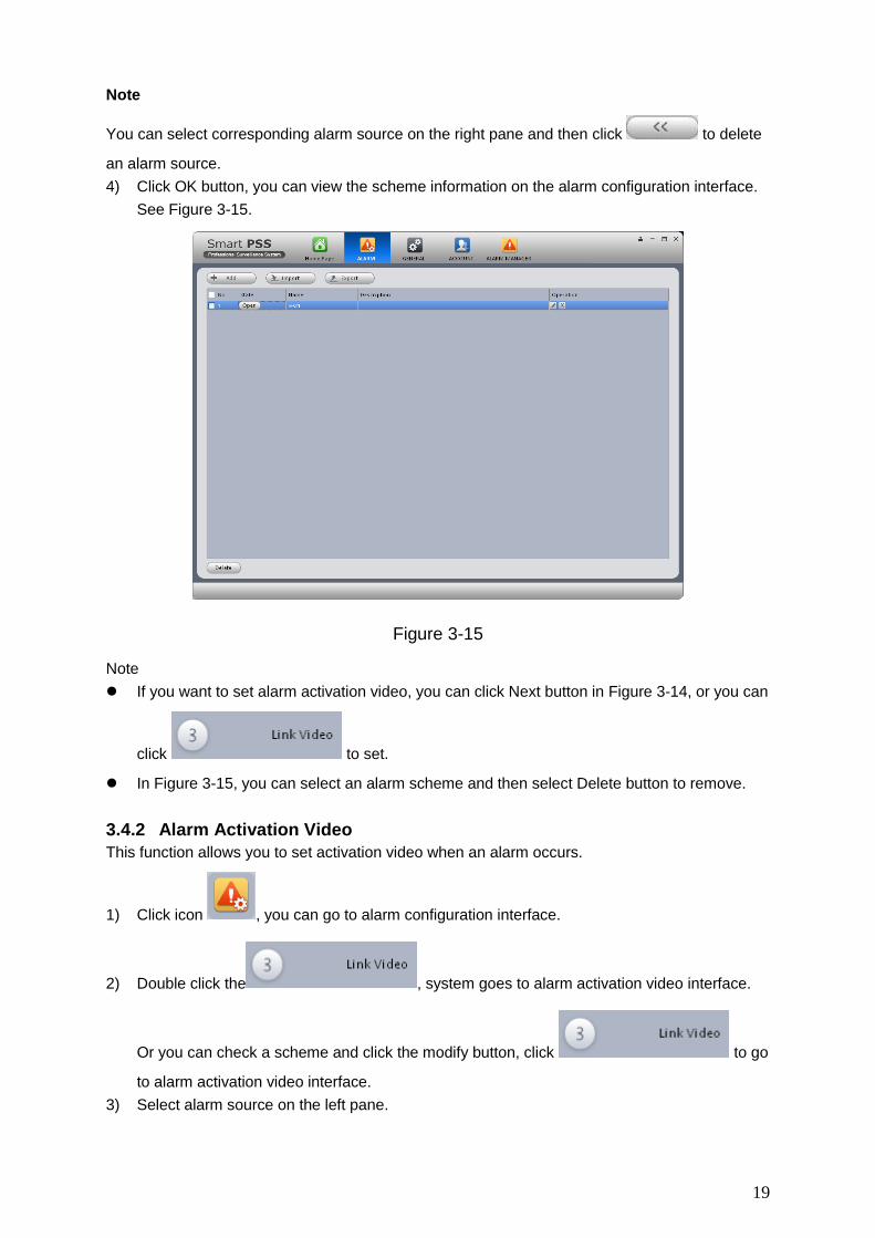
4) Click OK button, you can view the scheme information on the alarm configuration interface.
See Figure 3-15.
Figure 3-15
Note
If you want to set alarm activation video, you can click Next button in Figure 3-14, or you can
click to set.
In Figure 3-15, you can select an alarm scheme and then select Delete button to remove.
3.4.2 Alarm Activation Video
This function allows you to set activation video when an alarm occurs.
1) Click icon , you can go to alarm configuration interface.
2) Double click the , system goes to alarm activation video interface.
Or you can check a scheme and click the modify button, click to go
to alarm activation video interface.
3) Select alarm source on the left pane.

20
4) Click link video to set preset and stay time, check the activation channel and click .
Now you can view the alarm activation video on the right pane. See Figure 3-16.
Figure 3-16
Note
In Figure 3-16, you can double click preset or stay time to change its contents.
You can select a scheme and then click to remove activation video.
5) Click alarm output, you can go to alarm output interface. See Figure 3-17.
6) Here you can check the box to enable auto output device function and input stay time.
Please select channels from the device channel list and then click to add activation
output. Or you can change setup directly on the right pane.
7) Click OK button to complete setup.

21
Figure 3-17
3.4.3 Enable/Disable/Export Scheme
After you added scheme, click the Open on State column, you can see it becomes disable. Click
it again to enable current scheme, you can see state is open now. Click
/ button to import/export scheme.
3.5 TV Wall Configuration
This function allows you to output video to the TV wall. Please follow the steps listed below.
1) Click , system goes to TV wall setup interface. See Figure 3-18.
Figure 3-18
22
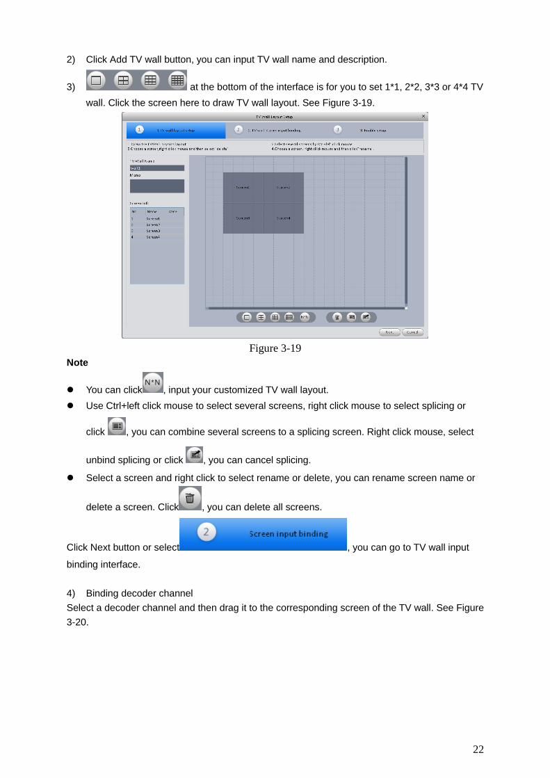
2) Click Add TV wall button, you can input TV wall name and description.
3) at the bottom of the interface is for you to set 1*1, 2*2, 3*3 or 4*4 TV
wall. Click the screen here to draw TV wall layout. See Figure 3-19.
Figure 3-19
Note
You can click , input your customized TV wall layout.
Use Ctrl+left click mouse to select several screens, right click mouse to select splicing or
click , you can combine several screens to a splicing screen. Right click mouse, select
unbind splicing or click , you can cancel splicing.
Select a screen and right click to select rename or delete, you can rename screen name or
delete a screen. Click , you can delete all screens.
Click Next button or select , you can go to TV wall input
binding interface.
4) Binding decoder channel
Select a decoder channel and then drag it to the corresponding screen of the TV wall. See Figure
3-20.

23
Figure 3-20
Click Next button, or click , you can go to enable status
interface.
5) Check the box to enable setup immediately and then click Finish button, you can see an
interface shown as in Figure 3-21.
Figure 3-21
In Figure 3-21, double click a TV wall, or select a TV wall and then click Modify button, you can
change its setup. You can also click Delete button to remove.
3.6 Tour
It is to realize monitor tour among each window. Please follow the steps listed below to set.

24
1) Click icon , you can go to monitor tour interface.
2) Click Add button to go to add task interface. See Figure 3-22.
3) Input task name, task description, and select window amount.
4) Drag channel(s) on the right pane to the list on the left pane.
You can use / button to adjust tour sequence. You can click
button to channel(s) you have added.
Double click newly added channel, you can change stay time, preset and bit stream type.
Figure 3-22
5) Click OK button, you can see an interface shown as in Figure 3-23.

25
Figure 3-23
In Figure 3-23, you can click button or to import/export tasks. You
can select a task and then click or to change or modify task.
3.7 PC-NVR
This function allows you to storage record file on the PC to effectively use wideband. You can
add, modify or delete PC-NVR and set PC-NVR parameter. Please follow the steps listed below.
1) Click icon , you can go the PC-NVR interface. See Figure 3-24.

26
Figure 3-24
2) Add PC-NVR
a) Click Add button, you can see an interface shown as in Figure 3-25.
Figure 3-25
b) Please input PC-NVR name, IP, port, user name and password.
c) Click Add button. You can go to Figure 3-24 to see there is a newly added item under
service list. See Figure 3-26.

27
Figure 3-26
Tips
You can click Auto search button in Figure 3-24 or Figure 3-25 to add searched PC-NVR directly.
3) Set PC-NVR
a) In Figure 3-26, click Setup button on the left pane, you can go to the setup interface.
b) You can see there are four items on the left pane: General setup, network setup, user
manager and disk manager. Here you can set system time, record length, device name,
port number and etc.
c) Select disk manager, you can select a disk and then click to implement disk
allocation operation. See Figure 3-27.

28
Figure 3-27
4) Binding record channel
Click Record button, drag the device channel on the device list to the corresponding of the PC-
NVR, click Save button.
5) Save record storage plan
a) Click button, you can go to the following interface. See Figure 3-28.
Figure 3-28
b) Select a channel from the dropdown list and click Set button. System pops up the
following interface for you to set. See Figure 3-29.

29
Figure 3-29
c) Please set the corresponding time and then click OK button.
Tips
After you complete setup for one channel, you can click Copy button in Figure 3-28 to copy
current setup to other channel(s). Please drag the channel to another channel you desire to save
the setup.

30
4 Basic Operation
4.1 Preview
4.1.1 Real-time Preview
After you set channel group, you can realize real-time preview, record, snap, PTZ operation and
etc.
On the main interface, click , you can go to the preview interface. See Figure 4-1.
Figure 4-1
Please refer to the following sheet for detailed information.
SN Item Function
1 Video window
Real-time video
2 Task window
Select and enable a task.
Note
If you have added task in the monitor task interfacem you can select corresponding task hter and enable it. Fot detailed operation, please refer to chapter3.6.
If you right click mouse and then select Save as a video task, you can save current video window and the channel open in current window as a task, you can select task and then enable.
3 Window split mode
Here you can set window split mode. You can drag the slide bar
or use to select 8 window modes.

31
SN Item Function
4 H/W ratio It is for you to set window height/width ratio. It is to adjust the window to the original size or the suitable scale.
5 Full-screen It is to go to full-screen mode. You can double click window or right click mouse to select exit full screen.
6 Device
Display device and channel.
For a device or a channel that is not included in the a group, you can not view the device or the channel on the device list.
7 PTZ It is to set PTZ preset, tour, aux function and etc.
8
Bit stream information and shortcut operation
Here you can view bit stream information and short cut operation.
Turn on/off the audio.
Turn on/off the microphone.
Turn on/off record.
Snapshot.
Select a preview window, double click device channel on the right pane to open the video.
Double click a group name; you can open all channels under current group. Right click device
channel, you can switch between main stream/extra stream.
Right click preview window, you can see an interface shown as in Figure 4-2.
Figure 4-2
Please refer to the following sheet for detailed information.
Item Function
Close video Click it to close current window.
Close all video Click it to close all windows.
Start record Save audio/video of current window to a record file.
Snapshot Snapshot current window. Click it once to save one picture.
Triple Snapshot Snapshot current window. Click it once to save three pictures by default.
Stream type Switch between main stream/extra stream
32
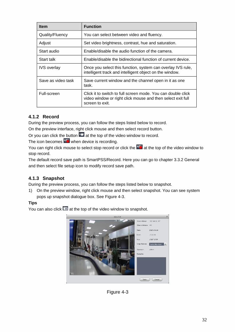
Item Function
Quality/Fluency You can select between video and fluency.
Adjust Set video brightness, contrast, hue and saturation.
Start audio Enable/disable the audio function of the camera.
Start talk Enable/disable the bidirectional function of current device.
IVS overlay Once you select this function, system can overlay IVS rule, intelligent track and intelligent object on the window.
Save as video task Save current window and the channel open in it as one task.
Full-screen Click it to switch to full screen mode. You can double click video window or right click mouse and then select exit full screen to exit.
4.1.2 Record
During the preview process, you can follow the steps listed below to record.
On the preview interface, right click mouse and then select record button.
Or you can click the button at the top of the video window to record.
The icon becomes when device is recording.
You can right click mouse to select stop record or click the at the top of the video window to
stop record.
The default record save path is SmartPSS/Record. Here you can go to chapter 3.3.2 General
and then select file setup icon to modify record save path.
4.1.3 Snapshot
During the preview process, you can follow the steps listed below to snapshot.
1) On the preview window, right click mouse and then select snapshot. You can see system
pops up snapshot dialogue box. See Figure 4-3.
Tips
You can also click at the top of the video window to snapshot.
Figure 4-3

33
2) Please select corresponding parameter from the snapshot reason dropdown list and then
input the information in the Remarks column.
3) Click save button, you can see system prompts “Successfully snapshot”.
On the Preview window, right click mouse and then click Triple snapshot, you can snap three
pictures at one time. You can see the corresponding dialogue box if the snapshot succeeds.
The default picture save path is SmartPSS/capture. Here you can go to chapter 3.3.2 General
and then select file setup icon to modify picture save path.
4.1.4 PTZ
If the device type is Speed dome, you can click the PTZ button to set. See Figure 4-4.
Figure 4-4
Please refer to the following sheet for detailed information.
Item Function
Direction buttons
It is to set PTZ movement direction. There are total 8 directions. Top/bottom/left/right/top left/top right/bottom left/bottom right.
Digital zoom (High-speed
PTZ)
It allows you to zoom in or zoom out the specified zone.
Please note, you can only use mouse to control.
Step It is to control PTZ movement speed. It supports value 1 to value 8.
Zoom It is to control speed dome to realize zoom function.

34
Item Function
Focus It is to adjust video definition.
Iris It is to adjust brightness.
Preset
You can set camera to a specified preset.
Use direction keys to move the camera to your desired location and then input preset value. Click Set button, you have set one preset.
Tour
This function allows the camera to move between several presets.
Please note as long as your speed dome supports preset funciton, it supports tour funcion.
Aux It is to call light, wiper, PTZ menu, auto rotation, aux 1, and aux 2.
4.1.4.1 Preset
This function allows you to set camera to a specified position.
Preset setup
1) In Figure 4-4, Use direction keys to move the camera to your desired location.
2) Click Preset button and then click setup button; you can see an interface shown as in Figure
4-5.
3) Input preset number and name, click Setup button on the right pane.
4) Click OK button to complete the setup.
Figure 4-5
Call preset
In Figure 4-4, click Preset button, select a value from the dropdown list and then click Goto
function, you can call a preset.
4.1.4.2 Tour
This function allows camera to go between several presets.
Important
Before you use this function, please set at least two presets first.

35
Tour setup
1) In Figure 4-4, click Tour button and then click Set.
2) System pops up the following dialogue box. See Figure 4-6.
Figure 4-6
3) Click New button, you can see the following interface. See Figure 4-7.
4) Input tour number and tour name and then select preset number from the dropdown list.
5) Click Add button to add one preset to the tour. Select another preset number from the
dropdown list and then click Add button again to add more preset to the tour.
6) Click OK button to complete the tour setup.
Figure 4-7
Now you can see an interface shown as in Figure 4-8.

36
Figure 4-8
Click Quit button to exit.
Call tour
In Figure 4-4, select corresponding tour value from the dropdown list and then click Start button,
you can call it.
4.2 Playback
After you recorded a file, you can go to this interface to playback.
On the main interface, click , you can go to the playback interface. See Figure 4-9.
Figure 4-9

37
4.2.1 Playback Record
Important
System can only search records of the storage plan. It can not search the local record
(The record files are saved to the default path “SmartPSS/Record”.)
Please follow the steps listed below to search the record you want and then playback.
1) Check channel on the device list on the top right pane.
2) Select search time.
3) Click the button on the left bottom to select record type.
4) Click Search button. You can see corresponding date is green if there is a record on current
data. You can see the corresponding dialogue box if there is no record.
5) Now you can see playback window. See Figure 4-10.
Figure 4-10
Please refer to the following sheet for detailed information.
SN Item Function
1 Shortcut operation column
There are shortcut operations to download record file and snapshot.
:Download record file.
:Snapshot.
2 Playback window
Playback record.

38
SN Item Function
3 Playback tool bar
It is to control the playback process, audio and etc:
:Window sync operation button. When this
function is enabled, the operation of the playback
bar is for all windows. When it is in status, it is for current selected window only.
:It is to switch playback and pause.
:Stop playback.
:Frame by frame backward.
:Frame by frame forward.
: It is to control the
playback speed.
:It is to adjust volume.
4
Record playback type and time process bar
It is to set record type and time line when playback. Click to set record type.
5 Time bar control
It is to zoom in /zoom out time line.
6 Device list
Display device and channels.
Note
For a device or a channel that is not included in the group management mode, you can not view it on the device list of the Preview interface.
7 Date Select record date.
8 Download manager
It is to manage download files.
9 Search Click it to search record.
10 Window display mode setup
It is to set window split mode, h/w ratio, and full-screen or
not. You can drag the slide bar or to set 8 modes.
4.2.2 Record List
Click button at the top right corner of the playback window. System pops up the following
interface. You can set to download by time or by record.
Click by file, check the file(s) you want to download and then click Download button. See Figure
4-11.

39
Figure 4-11
Click to select download by time, please input download period and then click Download button.
See Figure 4-12.
Figure 4-12
During the download process, you can click the download manager at the right bottom to view
download status, current download operation and download records. See Figure 4-6.
Here you can implement download, pause, delete operation and etc.

40
Figure 4-13
4.3 Alarm Manager
If you have set alarm scheme, you can see the corresponding alarm in the Alarm manager
interface. You can refer to chapter 3.4.1 to set alarm scheme first.
Click icon on the main interface, you can go to Alarm manager interface. See Figure 4-14.
Figure 4-14

41
Click alarm list, system displays all alarms and can display them by their level.
Click query list, check corresponding channel on the right pane and then select alarm type, start
time. Click Search button, you can see all alarm records matching the criteria you set here. See
Figure 4-15.
Figure 4-15
4.4 Alarm Activation
If you have set alarm activation video function in your alarm scheme setup (chapter 3.4.2), you
can see system pops up video window when a corresponding alarm occurs. See Figure 4-14.
If you check the box at the bottom of the interface to pause refresh, the new alarm activation
video will not overwrite current one. Click Alarm Manager at the right bottom of the interface,
system goes to the alarm manager interface for you to view the corresponding alarm record.

42
Figure 4-16
4.5 TV Wall
After you set TV wall setup (chapter 3.5 ), you can output video to the TV wall. You can follow the
steps listed below to set.
1) Click icon on the main interface, you can go to the following interface. See Figure 4-17.
Figure 4-17
2) Select corresponding TV wall from the screen information dropdown list. You can check to
select real-time mode if necessary. Once you enable real-time mode, system automatically
output the video to the TV wall after you complete the setup. Otherwise, it does not output
the video to the TV wall.
3) Drag the channel on the right pane to the corresponding screen and then binding.

43
Tips
Select one screen and then use the process bar you can set
four modes: 1/4/9/16-window. You can see the corresponding dialogue box, if current screen
does not support the mode you set here.
4) Click save as task button, you can see system pops up a dialogue box for you to input task
name.
5) Please input task name and click Save button.
6) Click Output video.
Please note:
You can select TV wall task from the task name dropdown list and then click the Output
video button to view the video.
Click task manager, you can view current task status. Or you can select one task and
click or to modify or delete current task.
4.6 E-map
Click icon on the main interface, you can go to the e-map interface. You can view the
device on the e-map. On the preview map interface, you can zoom e-map or open video, but you
can not edit it. On the Edit e-map interface, you can edit e-map, add camera and etc.
4.6.1 Edit E-map
Click , you can go to the following interface. See Figure 4-18.Click Tools, you can edit e-
map, delete e-map, delete device, add area, modify area, delete area and etc.
Drag a channel on the right pane to the e-map; you can add it to the e-map.
Figure 4-18
44
If you are in full-screen mode, you can see a function bar shown as below. See Figure 4-19.
Figure 4-19
Please refer to the following sheet for detailed information.
Item Function
Modify e-map It is for you to change e-map name, picture, description
Delete e-map Delete current e-map.
Delete device Delete a device from the e-map.
Add area Add hot zone on the e-map.
Modify area Change hot zone map name, picture and description.
Delete area Delete corresponding hot zone.
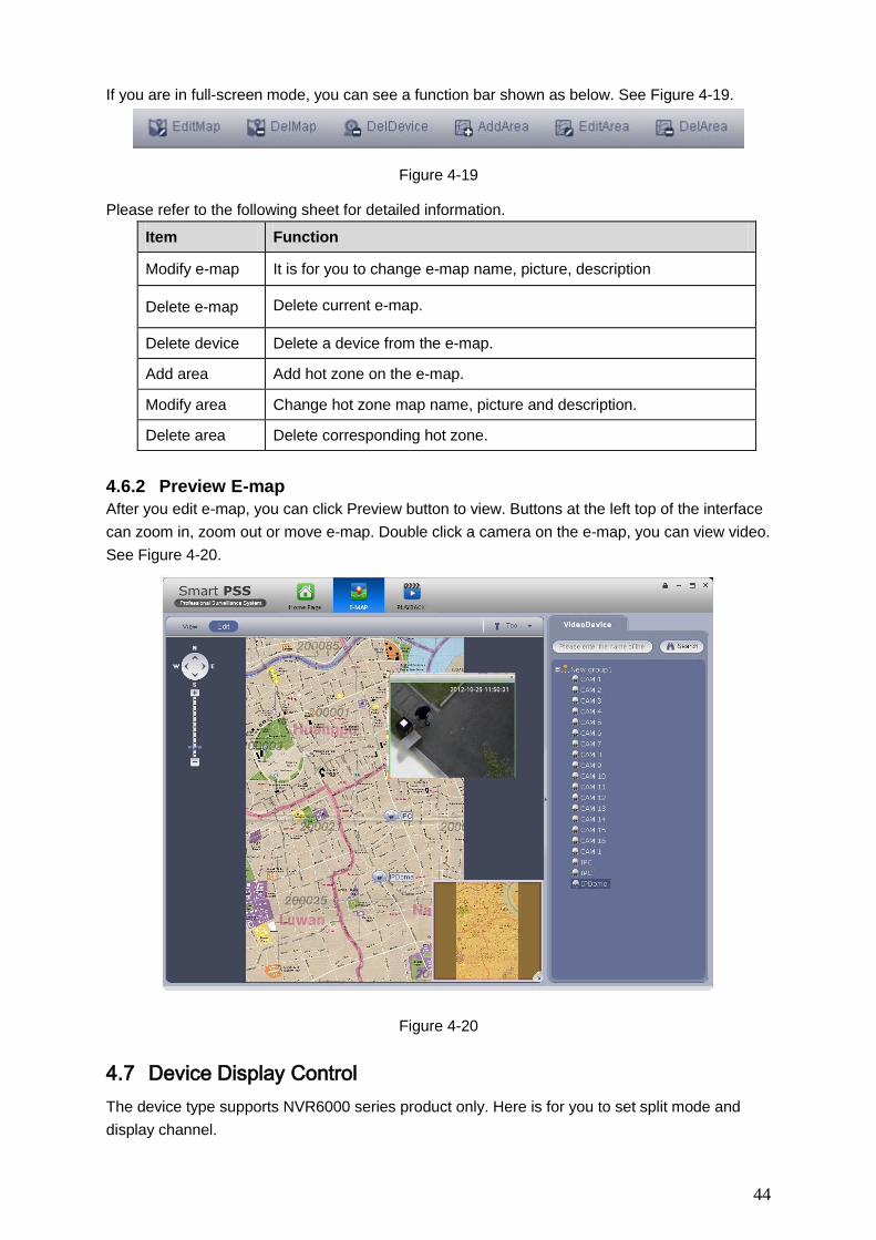
4.6.2 Preview E-map
After you edit e-map, you can click Preview button to view. Buttons at the left top of the interface
can zoom in, zoom out or move e-map. Double click a camera on the e-map, you can view video.
See Figure 4-20.
Figure 4-20
4.7 Device Display Control
The device type supports NVR6000 series product only. Here is for you to set split mode and
display channel.
45
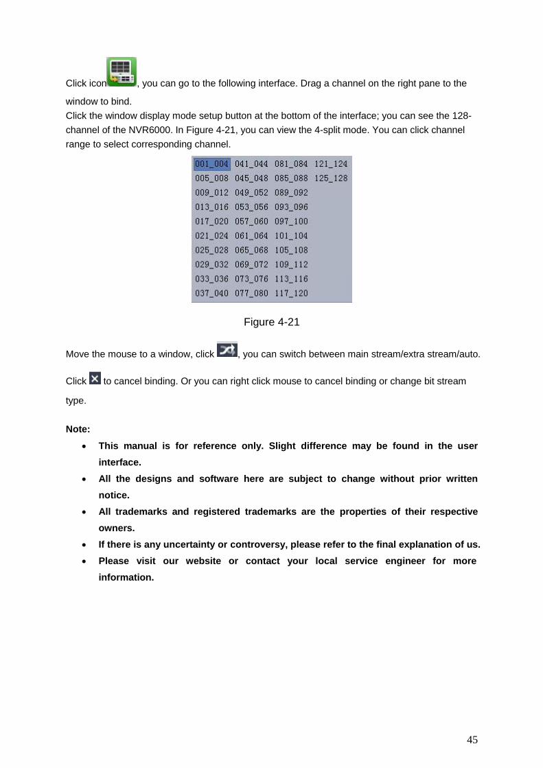
Click icon , you can go to the following interface. Drag a channel on the right pane to the
window to bind.
Click the window display mode setup button at the bottom of the interface; you can see the 128-
channel of the NVR6000. In Figure 4-21, you can view the 4-split mode. You can click channel
range to select corresponding channel.
Figure 4-21
Move the mouse to a window, click , you can switch between main stream/extra stream/auto.
Click to cancel binding. Or you can right click mouse to cancel binding or change bit stream
type.
Note:
This manual is for reference only. Slight difference may be found in the user
interface.
All the designs and software here are subject to change without prior written
notice.
All trademarks and registered trademarks are the properties of their respective
owners.
If there is any uncertainty or controversy, please refer to the final explanation of us.
Please visit our website or contact your local service engineer for more
information.