Embed Size (px)
Citation preview

SMART CONTROLmayfl wer

Contents
Lighting Control 3
How it works 4
Integrated Smart City Network 5
External Node 6
Sub Master 7
S6000 Socket 8
Internal Node 9
Antenna (Stub) 10
Antenna (Puck) 11 10
4
5
SMART CONTROL

From the early development of Central Management Systems (CMS), the nameMayflower has been at the forefront of research and development. As a market leader, Mayflowerprovides a 21st Century solution for themanagement of exterior lighting andassociated illuminated equipment.The Mayflower CMS allows full dynamic control and monitoring of each individual lighting unit using low power radio and GPRS/3G communication. Discrete infrastructure installed on lighting units receives and transmits data to the Back Office enabling full and effective asset management. Whether it’s new or existing lighting orsignage installations, Mayflower can giveyou the power to take control.
Lighting Control
Complete lighting control Reduced CO2 emissionsEnergy savings Increased financial savings Reduced maintenance and scouting costs Patented socket and security design Elexon approved – CMS equivalent meter system DALI and 0-10V
Benefits
2G / 3G connectivity Self-healing mesh networkSecure open protocol Fully hosted or client hosted options Easy planning with Google mapping Simple installation and commissioning Patented socket technology DALI and 0-10 Volt ballast compatibility Over The Air system upgrades (OTA) Solutions for all lighting and signage infrastructure5/7 Pin ANSI Standard C136.41 compatible
System Features
Elexon approved CMS equivalent meter system DALI or 0-10 Volt
Provides full flexible control of lighting infrastructure
SMART CONTROL
How it works
quick, easy and simple to install
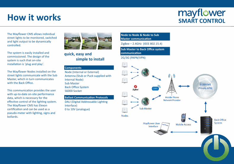
The Mayflower CMS allows individual street lights to be monitored, switched and light output to be dynamically controlled.
The system is easily installed andcommissioned. The design of thesystem is such that on-siteinstallation is ‘plug and play’.
The Mayflower Nodes installed on thestreet lights communicate with the SubMaster, which in turn communicateswith the Back Office.
This communication provides the userwith up-to-date on-site performancedata, which is necessary for theeffective control of the lighting system.The Mayflower CMS has Elexon certification and can be used as a pseudo-meter with lighting, signs and bollards.
Patent Number
ComponentsNode (Internal or External)Antenna (Stub or Puck supplied withInternal Node)Sub MasterBack Office SystemS6000 Socket
Ballast Communication ProtocolsDALI (Digital Addressable Lighting Interface)0 to 10V (analogue)
Node to Node & Node to Sub Master communication
ZigBee – 2.4GHz (IEEE 802.15.4)
Sub Master to Back Office systemcommunication2G/3G (PAPN/VPN)
Approvals
SMART CONTROL

Approvals
Mayflower CMS represents the 21st century solution for management of highway lighting and illuminated equipment. Mayflower (CMS) provides remote control, monitoring and energymeasurement of street lighting over awireless interface (ZigBee\Cellular). The functionality of the system givesasset managers the ability to monitorand report faults automatically, controlswitching and vary light output as well asmanage energy consumption. Mayflower is involved in some of the largest street lighting projects in the UK, including projects in the City of Southampton and the County of Hampshire.
These areas now have a ‘Smart City’ network ready for future IoTapplications. To date Mayflower hassupplied and is controlling nearly320,000 lighting units across 30 localauthorities in the UK and Ireland.
The Hampshire PFI (25 year) project includes approximately 150,000 Mayflower nodes, making it the world’s largest single CMS network. The Mayflower CMS and productshave received Elexon approval andcan be used as equivalent meters formeasuring energy usage.
Integrated Smart City Network SMART CONTROL

An external Mayflower node is installed onto a luminaire to control the on/off /dim function and reports back energy consumption information. It is installed using either the Mayflower S6000 socket or an ANSI Standard C136.41 compliant dimming receptacle.
The Node receives lamp control commands from the Mayflower Sub Master.
The Node monitors and records measurement data and can alert the user to potential fault issues, such as a change in lamp status.
External Node
Product CodeEXIII/ DALIEXIII/ 0-10V
Elexon Charge Code9800010010100
EnclosureIP67UV stableFlame retardantCompatible with Mayflower Electrical and mechanical inter-connection; S6000 socket or ANSI Standard C136.41
Node CommunicationZigbee IEEE 802.15.4Licence freeMulti-channelDynamically configured mesh networkingSelf-healing capabilityRange: up to 200m
Ballast Communication ProtocolsDALI (Digital Addressable Lighting Interface)0 to 10V (analogue)
Radio TransceiverFrequency: 2405-2480MHzModulation: O-QPSKOutput power: <10 dBmTemperature: -30degC to +70degC
Power SupplyVoltage: 230V 50HzPower consumption: <1WSupply voltage tolerance: +10% to -6%Voltage surge protection: 2KVOver current protection required: 10A BS88 or equivalent
MeasurementEnergy meter microchip controlsup to four electronic drivers in oneluminaire packageAccuracy: +/-1%Voltage span: 90 to 265 VAC, 50/60HzCurrent rating: 4A maximum
SwitchingEnergy efficient latching relayRelay rating: 16A, 250V high in-rush
MicrocontrollerFlash programmable CPUBrown-out protectionWatch-dog timer protectionRun time clock plus 48hr supply protection
ApprovalsUK/EU ApprovalsEN55015:2006 + A1 + A2EN61547:2009EN 301 489-1:2011FCC 47 CFR Part 15 Class AFCC Part 15 Subpart C, 15.247EN 300 328IEC 61347-2-11:2011IEC 61347-1:2007+A2:2012IEC 61010 1:2010ETSI EN 019-2-4: V2.2.2
AUS/NZ ApprovalsAS/NZS 61010.1:2003AS/NZS 4268:2012+A1:2013
SMART CONTROL

Control commands issued by the Mayflower Central Management System (CMS) are propagated from the Sub Master which acts as the wireless gateway between the Back OfficeSystem and the Nodes.
The Sub Master communicates with the Back Office System via secure 2G/3G links.
Up to 500 Mayflower Nodes can be connected to a single Sub Master using a wireless mesh open-communication protocol called ZigBee.
Sub Master
Patent NumberGB23272160
Product CodeEXIII/SM/DALIEXIII/SM/0-10V
SwitchingEnergy efficient latching relayRelay rating: 16A, 250V high in-rush
Switching ControlLux level switching based on three photo sensorsAstral ClockTen programmable switching actions per day(7 day programme) x10Five programmable fail safe switching actions
EnclosureIP67UV stableFlame retardantCompatible with Mayflower Electrical and mechanical inter-connection; S6000 socket or ANSI Standard C136.41
MeasurementEnergy meter microchipAccuracy: +/-1%Voltage span: 90 to 265 VAC, 50/60Hz
Elexon Charge Code9800020008100
Radio TransceiverFrequency: 2405-2480MHzModulation: O-QPSKOutput power: <10 dBmTemperature: -40degc to +70degCApprovals: ETSI EN300-328;EMC as per EN-301-489-1/17; EN60950
SwitchingEnergy efficient latching relayRelay rating: 16A, 250V high in-rush
MicrocontrollerFlash programmable CPUBrown-out protectionWatch-dog timer protectionRun time clock plus 48hr supply protection
Back Office CommunicationWeb based graphical user interface 2G/3G multi carrier SIMNetwork security: Secure Socket Layer (SSL)Private Access Name Point (APN)Virtual Private Network (VPN)
Node CommunicationZigbee IEEE 802.15.4Licence freeMulti-channelDynamically configured mesh networkingSelf-healing capabilityRange: Up to 200m
Ballast Communication ProtocolsDALI (Digital Addressable Lighting Interface)0 to 10V (analogue)
Power SupplyVoltage: 230V 50HzPower consumption: <2WSupply voltage tolerance: +10% to -6%Voltage surge protection: 2KVOver current protection required: 10A BS88 or equivalent
SMART CONTROL

Often referred to as a NEMA socket, theS6000 is a patented socket designed around the lighting industry’s standard photocell socket (BS5972). The S6000 Socket allows the installation of external Mayflower Nodes or Sub Masters to lanterns.The unique design provides three additional connections required for communication with either DALI or 0-10V ballasts.
The socket can be used with both the Mayflower external Node and Sub Master. It can also be used with a standard photocell if the installationof the Node/Sub Master is to take place after lantern installation.
S6000 Socket
UK Patent Number2480091B
Wiring DiagramAustralian Patent Application Number2011249592
Japanese Patent Application Number2013-508556
Voltage Rating230V 50Hz
EnclosurePolycarbonate
UK Patent Number2480234B
European Patent Application Number11719055.3
TypeBS5972
ContactsNickel plated Phosphor Bronze
Product CodeS6000
Current Rating10A
US Patent Number9,077,112
South African Patent Number2012/08383
SMART CONTROL

An internal Mayflower node is installed within a luminaire to control the on/off /dim function and reports back energy consumption information. It is has been designed to fit within a luminaire body for situations where it is not practical or aesthetically pleasing to fit an external control solution e.g. bollards, signs, heritage and designer lanterns.
In conjunction with the Mayflower Antenna, the Mayflower Node receives lamp control commands from the Mayflower Sub Master. The Mayflower Node is able to monitor, record andtransmit measurement data, as well as alerting the user to potential fault issues.
Internal Node
Product CodeINTIII/DALIINTIII/0-10V
Power SupplyVoltage: 230V 50HzPower consumption: <1WSupply voltage tolerance: +10% to -6%Voltage surge protection: 2KVOver current protection required: 10A BS88 or equivalent
SwitchingEnergy efficient latching relayRelay rating: 16A, 250V high in-rush
Node CommunicationZigbee IEEE 802.15.4Licence freeMulti-channelDynamically configured mesh networkingSelf-healing capabilityRange: Up to 200m
Ballast Communication ProtocolsDALI (Digital Addressable Lighting Interface)0 to 10V (analogue)
Radio TransceiverFrequency: 2405-2480MHzModulation: O-QPSKOutput power: <10 dBmTemperature: -20˚c to +65˚c
EnclosureIP42UV stableFlame retardant
MeasurementEnergy meter microchipAccuracy: +/-1%Voltage span: 90V to 260VCurrent span: 50mA to 4AWattage span: 1W to 1000W
MicrocontrollerFlash programmable CPUBrown-out protectionWatch-dog timer protectionRun time clock plus 48hr supply protection
AntennaIP6511mm fixing hole
Elexon Charge Code9800010011100
UK/EU ApprovalsEN55015:2006 + A1 + A2EN61547:2009EN 301 489-1:2011FCC 47 CFR Part 15 Class AFCC Part 15 Subpart C, 15.247EN 300 328IEC 61347-2-11:2011IEC 61347-1:2007+A2:2012IEC 61010 1:2010 AUS/NZ ApprovalsAS/NZS 61010.1:2003AS/NZS 4268:2012+A1:2013
SMART CONTROL

A 2.4GHz Mayflower Antenna providing a tamper resistant solution to enable the Mayflower Internal Node to communicate with the Sub Master.
It is installed through a 20mm hole on the lighting unit. An adhesive foam compression ring provides an IP65 seal.
The Mayflower Antenna is designed to be ground plane independent and is supplied with 700mm low loss cable, terminated with a male SMA connector.
Product Code
Enclosure
AN/ND/T2-STUB
RF PropertiesOperating frequency: 2.4-2.5GHzAntenna type: Quarter waveInput resistance: 50ΩVSWR: <2:1Polarization: VerticalPeak gain: 2 dBiBeam width: Omni directional
CableCable type: RG174Cable length: 70cmConnector: SMA-Male
Fitting InstructionsWhen fitting antenna make sure that lantern surface is cleaned and sticker has been removed from adhesive pad, so that Antenna will seal properly to the lantern body.
ComplianceIP65RoSH complianceREACHUL94-V0UV stableCE/IEC 60950-22IK06 to BSEN50102
Main body material: Polycarbonate Black UL94-V0Fitting: Body mountFitting diameter: 20mmThread length: 25mm x M20Lock nut: NylonOperating temperature range: -40°c to + 80°c
Antenna (Stub) SMART CONTROL

A 2.4GHz Mayflower Antenna providing a tamper-resistant solution to enable the internal Mayflower Node to communicate with the Sub Master.
It is installed through a small 11mm hole on the lighting unit and is anchored by a threaded base. An adhesive foam compression ring provides an IP65 seal.
The Mayflower Antenna is designed to be ground plane independent and is supplied with a 500mm coax feed, terminated with a male SMA connector.
It can also be supplied with a 20mm adapter to allow it to be retro-fitted in the place of a miniature photo-electric cell.
Product Code
Enclosure
AER08005
RF PropertiesFrequency: 2.4GHzNominal impedance: 50 Ohms Gain: 2 dBiVSWR: <2:1Polarisation: Vertical
CableType: RG174 Length: 50cm Connector: SMA Male
Fitting: BodymountIP Rating: IP65Size: Dia. 52mm x 18mm Working temperature: -40˚C to +85˚C
Antenna (Puck) SMART CONTROL

120345 076 7664 • [email protected] • www.mayflowercontrol.comMayflower Complete Lighting Control is a trading name of SSE Contracting Limited which is part of the SSE Group The Registered Office of SSE Contracting Limited is 55 Vastern Road Reading Berkshire RG1 8BU. Registered in England & Wales No 02317133
Central Management System
Dynamic lighting control
Smart City technology
SMART CONTROL
![W 16 Amp 230V, 50Hz Locking - Mastervolt Sweden AB · Locking Shore Power Cordset • H07BQ-F 3G 2.50 mm2 harmonized cable • IEC 60309 plug 2P+E [6H], 250V/50Hz • Watertight connector](https://img.pdfslide.net/doc/110x75/5f10bd507e708231d44a95c4/w-16-amp-230v-50hz-locking-mastervolt-sweden-ab-locking-shore-power-cordset-a.jpg)