Embed Size (px)
Citation preview

Smart Water Xtreme Technical Guide

-2- v7.2
Index
Document version: v7.2 - 11/2019© Libelium Comunicaciones Distribuidas S.L.
INDEX
1. General and safety information ......................................................................................................... 5
2. Important: Read before use ................................................................................................................ 6
3. Waspmote Plug & Sense! ..................................................................................................................... 73.2. General view ..................................................................................................................................................................................8
3.2.1. Specifications .................................................................................................................................................................8
3.2.2. Parts included ..............................................................................................................................................................11
3.2.3. Identification ................................................................................................................................................................12
3.3. Sensor probes .............................................................................................................................................................................14
3.4. Solar powered ............................................................................................................................................................................15
3.5. External Battery Module .........................................................................................................................................................16
3.6. Programming the Nodes ........................................................................................................................................................17
3.7. Program in minutes ..................................................................................................................................................................18
3.8. Radio interfaces .........................................................................................................................................................................19
3.9. Industrial Protocols...................................................................................................................................................................20
3.10. GPS ...............................................................................................................................................................................................22
3.11. Models ........................................................................................................................................................................................23
3.11.1. Smart Water Xtreme................................................................................................................................................24
4. Sensors probes .................................................................................................................................. 264.1. Important notes ........................................................................................................................................................................26
4.2. New Sensors for Waspmote Plug & Sense! Smart Water Xtreme ............................................................................28
4.2.1. Table 1: Parameters, units, ranges, resolutions and accuracies of every sensor ..................................28
4.2.2. Table 2: Applications and measuring principles .............................................................................................31
4.3. Optical dissolved oxygen and temperature OPTOD sensor probe .........................................................................35
4.3.1. Specifications ..............................................................................................................................................................35
4.3.2. Measurement process ..............................................................................................................................................36
4.3.3. Socket .............................................................................................................................................................................37
4.3.4. Maintenance ................................................................................................................................................................38
4.3.5. Installation ....................................................................................................................................................................48
4.3.7. Calibration report .......................................................................................................................................................50
4.4. pH, ORP and temperature PHEHT sensor probe ............................................................................................................51
4.4.1. Specifications ...............................................................................................................................................................52
4.4.2. Measurement process .............................................................................................................................................53
4.4.3. Socket .............................................................................................................................................................................54

-3- v7.2
Index
4.4.4. Maintenance ................................................................................................................................................................54
4.4.5. Installation ....................................................................................................................................................................62
4.4.6. Application examples ...............................................................................................................................................64
4.4.7. Calibration report .......................................................................................................................................................64
4.5. Conductivity, salinity and temperature C4E sensor probe ........................................................................................65
4.5.1. Specifications ..............................................................................................................................................................65
4.5.2. Measurement process ..............................................................................................................................................67
4.5.3. Socket .............................................................................................................................................................................67
4.5.4. Maintenance ................................................................................................................................................................68
4.5.5. Installation ....................................................................................................................................................................73
4.5.6. Application examples ...............................................................................................................................................75
4.5.7. Calibration report .......................................................................................................................................................75
4.6. Inductive conductivity, salinity and temperature CTZN sensor probe .................................................................76
4.6.3. Socket .............................................................................................................................................................................78
4.6.4. Maintenance ................................................................................................................................................................79
4.6.5. Installation ....................................................................................................................................................................85
4.6.6. Application examples ...............................................................................................................................................86
4.6.7. Calibration report .......................................................................................................................................................86
4.7. Turbidity and temperature NTU sensor probe ...............................................................................................................87
4.7.1. Specifications ...............................................................................................................................................................88
4.7.2. Measurement process ..............................................................................................................................................89
4.7.3. Socket .............................................................................................................................................................................90
4.7.4. Maintenance ................................................................................................................................................................90
4.7.5. Installation ....................................................................................................................................................................95
4.7.6. Application examples ...............................................................................................................................................97
4.7.7. Calibration report .......................................................................................................................................................97
4.8. Suspended solids, turbidity, sludge blanket and temperature MES5 sensor probe ........................................98
4.8.1. Specifications ...............................................................................................................................................................99
4.8.2. Measurement process ...........................................................................................................................................100
4.8.3. Socket ..........................................................................................................................................................................101
4.8.4. Maintenance .............................................................................................................................................................101
4.8.5. Installation .................................................................................................................................................................104
4.8.6. Application examples ............................................................................................................................................105
4.8.7. Calibration report ....................................................................................................................................................105
4.9. Temperature, humidity and pressure sensor probe (Bosch BME280) ..................................................................106
4.9.1. Specifications ............................................................................................................................................................106
4.9.2. Measurement process ...........................................................................................................................................107
4.9.3. Socket ..........................................................................................................................................................................108
4.9.4. Application examples ............................................................................................................................................108
4.10. Luminosity sensor probe (AMS TSL2561) ....................................................................................................................109

-4- v7.2
4.10.1. Specifications .........................................................................................................................................................109
4.10.2. Measurement process .........................................................................................................................................110
4.10.3. Socket .......................................................................................................................................................................110
4.10.4. Application examples..........................................................................................................................................110
4.11. Ultrasound sensor probe (MaxBotix MB7040) ...........................................................................................................111
4.11.1. Specifications .........................................................................................................................................................111
4.11.2. Measurement process .........................................................................................................................................112
4.11.3. Socket ......................................................................................................................................................................112
4.11.4. Installation ...............................................................................................................................................................113
4.11.5. Application examples..........................................................................................................................................113
4.12. Eureka Manta multi sensor probe ..................................................................................................................................114
4.12.1. Common specifications ......................................................................................................................................114
4.12.2. Fluorometer Chlorophyll ....................................................................................................................................115
4.12.3. Fluorometer Phycocyanin (freshwater BGA) ...............................................................................................115
4.12.4. Fluorometer Phycoerythrin (marine BGA) ...................................................................................................115
4.12.5. Fluorometer CDOM / FDOM .............................................................................................................................117
4.12.6. Ion selective electrode – Ammonium ...........................................................................................................117
4.12.7. Ion selective electrode – Nitrate......................................................................................................................117
4.12.8. Ion selective electrode – Chloride .................................................................................................................117
4.12.9. Ion selective electrode – Sodium ....................................................................................................................117
4.12.10. Ion selective electrode – Calcium .................................................................................................................117
4.12.11. Measurement process ......................................................................................................................................118
4.12.12. Socket .....................................................................................................................................................................119
4.12.13. Maintenance ........................................................................................................................................................119
4.12.14. Installation ............................................................................................................................................................121
4.12.15. Application examples .......................................................................................................................................121
4.13. Calibration solutions ...........................................................................................................................................................122
5. Board configuration and programming ........................................................................................ 1255.1. 5.1 Hardware configuration ..............................................................................................................................................125
5.2. API .................................................................................................................................................................................................125
5.2.1. Before starting to program ..................................................................................................................................125
5.2.2. Sending sensor values with the Frame class ................................................................................................126
6. Consumption ................................................................................................................................... 1276.1. Consumption table.................................................................................................................................................................127
7. Safety guides ................................................................................................................................... 1287.1. Turbidity calibration solution, 4000 NTU ........................................................................................................................128
7.2. KCl storage solution ...............................................................................................................................................................138
7.3. pH 4.00 Calibration Solution ...............................................................................................................................................147
Index

-5- v7.2
7.4. pH 7.00 Calibration Solution ..............................................................................................................................................150
7.5. pH 10.00 Calibration Solution ...........................................................................................................................................153
7.6. 0% Dissolved Oxygen Calibration Solution ...................................................................................................................156
7.7. ORP 225mV Calibration Solution .......................................................................................................................................159
7.8. Conductivity K=0.1, 1, 10 Calibration Solutions ...........................................................................................................161
8. API changelog .................................................................................................................................. 164
9. Documentation changelog ............................................................................................................. 165
10. Certifications .................................................................................................................................. 166
11. Maintenance ................................................................................................................................. 167
12. Disposal and recycling ................................................................................................................. 168

-6- v7.2
General and safety information
1. General and safety informationImportant:
• All documents and any examples they contain are provided as-is and are subject to change without notice. Except to the extent prohibited by law, Libelium makes no express or implied representation or warranty of any kind with regard to the documents, and specifically disclaims the implied warranties and conditions of merchantability and fitness for a particular purpose.
• The information on Libelium’s websites has been included in good faith for general informational purposes only. It should not be relied upon for any specific purpose and no representation or warranty is given as to its accuracy or completeness.
• Read carefully Limited Warranty and Terms and Conditions of Use before using “Waspmote Plug & Sense!”. • Do NOT open casing and do not damage black warranty stickers. If you do so, you will lose warranty. • Do not remove any of the connectors. • Do not allow contact between metallic objects and electronic parts to avoid injury and burns. • Never immerse equipment in any liquid. • Keep equipment within temperature range indicated in recommendation section. • Do not connect or power equipment using cables that have been damaged. • Place equipment in an area to which only maintenance personnel can have access (in a restricted access zone). • In any case keep children away from the equipment. • If there is a power failure, immediately disconnect from the mains. • If using a battery whether or not in combination with a solar panel as a power source follow the voltage and
current specifications indicated in the section “External solar panel connector”. • If a software failure occurs, contact Libelium technical support before doing any action by yourself. • Do not place equipment on trees or plants as they could be damaged by its weight. • Be particularly careful if you are connected through a software interface for handling the machine; if settings
of that interface are incorrectly altered, it could become inaccessible. • If you need to clean the node, wipe it with a dry towel. • If Waspmote Plug & Sense! needs to be returned please send it completely dry and free from contaminants. • Waspmote Plug & Sense! is not designed to be placed in hard environmental conditions, under dangerous
chemical elements, explosive atmospheres with flammable gases, high voltage installations or special installations. Please contact Libelium technical support to ensure your application is compatible with Waspmote Plug & Sense!.

-7- v7.2
Important: Read before use
2. Important: Read before useThe following list shows just some of the actions that produce the most common failures and warranty-voiding. Complete documentation about usage can be found at http://www.libelium.com/development. Failure to comply with the recommendations of use will entail the warranty cancellation.
Software:
• Upload code only using Waspmote IDE. If a different IDE is used, Waspmote can be damaged and can become unresponsive. This use is not covered under warranty.
• Do not unplug any connector while uploading code. Waspmote can become unresponsive. This use is not covered under warranty.
• Do not connect or disconnect any connector while Waspmote is on. Waspmote can become unstable or unresponsive, and internal parts can be damaged. This fact is not covered under warranty.
Hardware:
• Do not handle black stickers seals on both sides of the enclosure ( Warranty stickers). Their integrity is the proof that Waspmote Plug & Sense! has not been opened. If they have been handled, damaged or broken, the warranty is void.
• Do not open Waspmote Plug & Sense! in any case. This will automatically make the warranty void. • Do not handle the four metallic screws of Waspmote Plug & Sense!. They ensure waterproof seal. • Do not submerge Waspmote Plug & Sense! in liquids. • Do not place nodes on places or equipment where it could be exposed to shocks and/or big vibrations. • Do not expose Waspmote Plug & Sense! to temperatures below -20 ºC or above 60 ºC. • Do not power Waspmote with other power sources than the original provided by Libelium. Voltage and current
maximum ratings can be exceeded, stopping Waspmote working and voiding warranty. • Do not try to extract, screw, break or move Waspmote Plug & Sense! connectors far from necessary usage,
waterproof sealing can be damaged and warranty will be voided. • For more information: http://www.libelium.com • Do not connect any sensor on the solar panel connector and also do not connect the solar panel to any of
sensor connectors. Waspmote can be damaged and warranty void. • Do not connect any sensor not provided by Libelium. • Do not place Waspmote Plug & Sense! where water can reach internal parts of sensors. • Do not get the magnet close to a metal object. The magnet is really powerful and will get stuck. • Do not place the magnet close to electronic devices, like PCs, batteries, etc, they could be damaged, or
information could be deleted.

-8- v7.2
Waspmote Plug & Sense!
3. Waspmote Plug & Sense!The Waspmote Plug & Sense! line allows you to easily deploy Internet of Things networks in an easy and scalable way, ensuring minimum maintenance costs. The platform consists of a robust waterproof enclosure with specific external sockets to connect the sensors, the solar panel, the antenna and even the USB cable in order to reprogram the node. It has been specially designed to be scalable, easy to deploy and maintain.
Note: For a complete reference guide download the “Waspmote Plug & Sense! Technical Guide” in the Development section of the Libelium website.
3.1. Features • Robust waterproof IP65 enclosure • Add or change a sensor probe in seconds • Solar powered external panel option • Radios available: 802.15.4, 868 MHz, 900 MHz, WiFi, 4G, Sigfox and LoRaWAN • Over the air programming (OTAP) of multiple nodes at once (via WiFi or 4G radios) • Special holders and brackets ready for installation in street lights and building fronts • Graphical and intuitive interface Programming Cloud Service • Built-in, 3-axes accelerometer • External, contactless reset with magnet • Optional industrial protocols: RS-232, RS-485, Modbus, CAN Bus • Optional GPS receiver • Optional External Battery Module • External SIM connector for the 4G models • Fully certified: CE (Europe), FCC (USA), IC (Canada), ANATEL (Brazil), RCM (Australia), PTCRB (USA, cellular
connectivity), AT&T (USA, cellular connectivity)
Figure: Waspmote Plug & Sense!

-9- v7.2
Waspmote Plug & Sense!
3.2. General viewThis section shows main parts of Waspmote Plug & Sense! and a brief description of each one. In later sections all parts will be described deeply.
3.2.1. Specifications
• Material: polycarbonate • Sealing: polyurethane • Cover screws: stainless steel • Ingress protection: IP65 • Impact resistance: IK08 • Rated insulation voltage AC: 690 V • Rated insulation voltage DC: 1000 V • Heavy metals-free: Yes • Weatherproof: true - nach UL 746 C • Ambient temperature (min.): -30 °C* • Ambient temperature (max.): 70 °C* • Approximated weight: 800 g
* Temporary extreme temperatures are supported. Regular recommended usage: -20, +60 ºC.
In the pictures included below it is shown a general view of Waspmote Plug & Sense! main parts. Some elements are dedicated to node control, others are designated to sensor connection and other parts are just identification elements. All of them will be described along this guide.
164 mm
124 mm
175
mm
410
mm
160
mm
122
mm
85 mm
Figure: Main view of Waspmote Plug & Sense!

-10- v7.2
Waspmote Plug & Sense!
Figure: Control side of the enclosure
Control side of the enclosure for 4G model
Figure: Sensor side of the enclosure

-11- v7.2
Waspmote Plug & Sense!
Figure: Antenna side of the enclosure
Figure: Front view of the enclosure
Figure: Back view of the enclosure

-12- v7.2
Waspmote Plug & Sense!
Figure: Warranty stickers of the enclosure
Important note: Do not handle black stickers seals of the enclosure (Warranty stickers). Their integrity is the proof that Waspmote Plug & Sense! has not been opened. If they have been handled, damaged or broken, the warranty is automatically void.
3.2.2. Parts included
Next picture shows Waspmote Plug & Sense! and all of its elements. Some of them are optional accessories that may not be included.
1
2
34
5
7
68
9
10
Figure: Waspmote Plug & Sense! accessories: 1 enclosure, 2 sensor probes, 3 external solar panel, 4 USB cable, 5 antenna, 6 cable ties, 7 mounting feet (screwed to the enclosure), 8 extension cord, 9 solar panel cable, 10 wall plugs & screws

-13- v7.2
Waspmote Plug & Sense!
3.2.3. Identification
Each Waspmote model is identified by stickers. Next figure shows front sticker.
Model identification colour
Enclosure model
Figure: Front sticker of the enclosure
There are many configurations of Waspmote Plug & Sense! line, all of them identified by one unique sticker. Next image shows all possibilities.
Figure: Different front stickers

-14- v7.2
Waspmote Plug & Sense!
Moreover, Waspmote Plug & Sense! includes a back sticker where it is shown identification numbers, radio MAC addresses, etc. It is highly recommended to annotate this information and save it for future maintenance. Next figure shows it in detail.
Figure: Back sticker
Sensor probes are identified too by a sticker showing the measured parameter and the sensor manufacturer reference.
CO - TGS2442Measure
parameterSensor reference
Figure: Sensor probe identification sticker
-15- v7.2
Waspmote Plug & Sense!
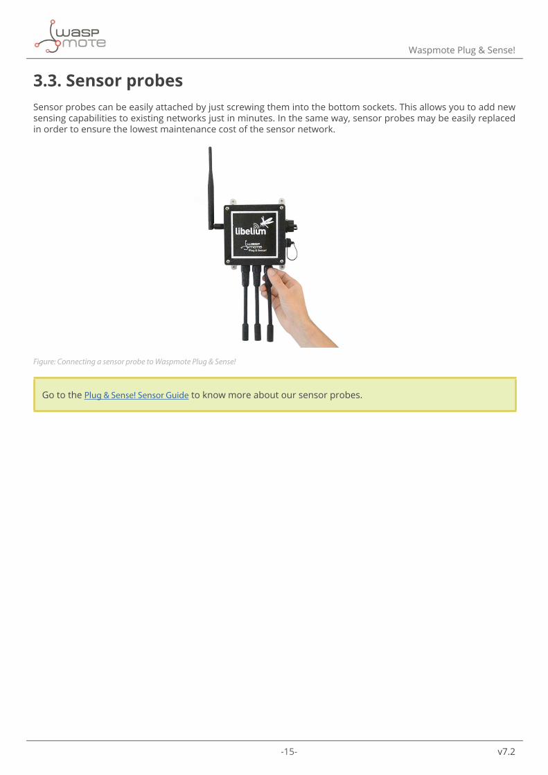
3.3. Sensor probesSensor probes can be easily attached by just screwing them into the bottom sockets. This allows you to add new sensing capabilities to existing networks just in minutes. In the same way, sensor probes may be easily replaced in order to ensure the lowest maintenance cost of the sensor network.
Figure: Connecting a sensor probe to Waspmote Plug & Sense!
Go to the Plug & Sense! Sensor Guide to know more about our sensor probes.

-16- v7.2
Waspmote Plug & Sense!
3.4. Solar poweredThe battery can be recharged using the waterproof USB cable but also the external solar panel option.
The external solar panel is mounted on a 45º holder which ensures the maximum performance of each outdoor installation.
Figure: Waspmote Plug & Sense! powered by an external solar panel

-17- v7.2
Waspmote Plug & Sense!
3.5. External Battery ModuleThe External Battery Module (EBM) is an accessory to extend the battery life of Plug & Sense!. The extension period may be from months to years depending on the sleep cycle and radio activity. The daily charging period is selectable among 5, 15 and 30 minutes with a selector switch and it can be combined with a solar panel to extend even more the node’s battery lifetime.
Note: Nodes using solar panel can keep using it through the External Battery Module. The EBM is connected to the solar panel connector of Plug & Sense! and the solar panel unit is connected to the solar panel connector of the EBM.
Figure: Plug & Sense! with External Battery Module
Figure: Plug & Sense! with External Battery Module and solar panel
-18- v7.2
Waspmote Plug & Sense!
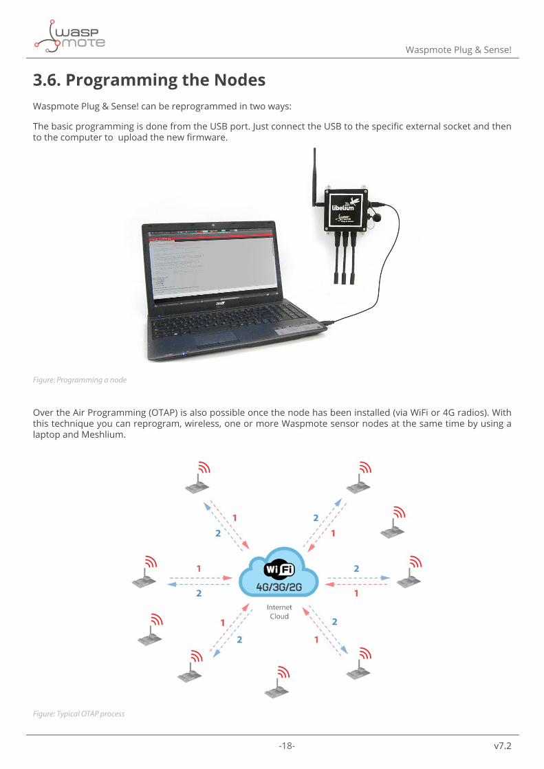
3.6. Programming the NodesWaspmote Plug & Sense! can be reprogrammed in two ways:
The basic programming is done from the USB port. Just connect the USB to the specific external socket and then to the computer to upload the new firmware.
Figure: Programming a node
Over the Air Programming (OTAP) is also possible once the node has been installed (via WiFi or 4G radios). With this technique you can reprogram, wireless, one or more Waspmote sensor nodes at the same time by using a laptop and Meshlium.
Figure: Typical OTAP process

-19- v7.2
Waspmote Plug & Sense!
3.7. Program in minutesThe Programming Cloud Service is an intuitive graphic interface which creates code automatically. The user just needs to to fill a web form to obtain binaries for Plug & Sense!. Advanced programming options are available, depending on the license selected.
Check how easy it is to handle the Programming Cloud Service at:
https://cloud.libelium.com/
Figure: Programming Cloud Service
-20- v7.2
Waspmote Plug & Sense!
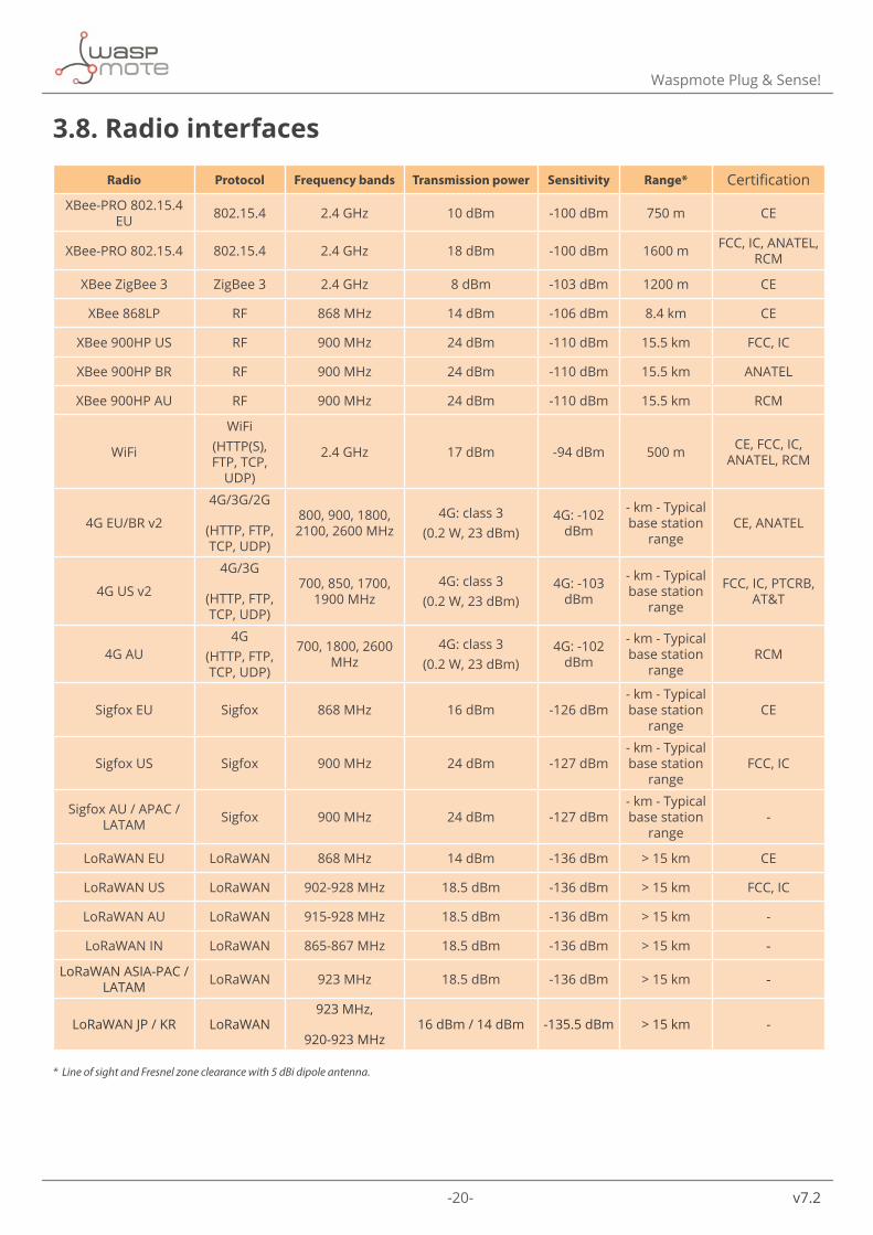
3.8. Radio interfaces
Radio Protocol Frequency bands Transmission power Sensitivity Range* Certification
XBee-PRO 802.15.4 EU 802.15.4 2.4 GHz 10 dBm -100 dBm 750 m CE
XBee-PRO 802.15.4 802.15.4 2.4 GHz 18 dBm -100 dBm 1600 m FCC, IC, ANATEL, RCM
XBee ZigBee 3 ZigBee 3 2.4 GHz 8 dBm -103 dBm 1200 m CE
XBee 868LP RF 868 MHz 14 dBm -106 dBm 8.4 km CE
XBee 900HP US RF 900 MHz 24 dBm -110 dBm 15.5 km FCC, IC
XBee 900HP BR RF 900 MHz 24 dBm -110 dBm 15.5 km ANATEL
XBee 900HP AU RF 900 MHz 24 dBm -110 dBm 15.5 km RCM
WiFi
WiFi(HTTP(S), FTP, TCP,
UDP)
2.4 GHz 17 dBm -94 dBm 500 m CE, FCC, IC, ANATEL, RCM
4G EU/BR v2
4G/3G/2G
(HTTP, FTP, TCP, UDP)
800, 900, 1800, 2100, 2600 MHz
4G: class 3 (0.2 W, 23 dBm)
4G: -102 dBm
- km - Typical base station
rangeCE, ANATEL
4G US v2
4G/3G
(HTTP, FTP, TCP, UDP)
700, 850, 1700, 1900 MHz
4G: class 3 (0.2 W, 23 dBm)
4G: -103 dBm
- km - Typical base station
range
FCC, IC, PTCRB, AT&T
4G AU4G
(HTTP, FTP, TCP, UDP)
700, 1800, 2600 MHz
4G: class 3 (0.2 W, 23 dBm)
4G: -102 dBm
- km - Typical base station
rangeRCM
Sigfox EU Sigfox 868 MHz 16 dBm -126 dBm- km - Typical base station
rangeCE
Sigfox US Sigfox 900 MHz 24 dBm -127 dBm- km - Typical base station
rangeFCC, IC
Sigfox AU / APAC / LATAM Sigfox 900 MHz 24 dBm -127 dBm
- km - Typical base station
range-
LoRaWAN EU LoRaWAN 868 MHz 14 dBm -136 dBm > 15 km CE
LoRaWAN US LoRaWAN 902-928 MHz 18.5 dBm -136 dBm > 15 km FCC, IC
LoRaWAN AU LoRaWAN 915-928 MHz 18.5 dBm -136 dBm > 15 km -
LoRaWAN IN LoRaWAN 865-867 MHz 18.5 dBm -136 dBm > 15 km -
LoRaWAN ASIA-PAC / LATAM LoRaWAN 923 MHz 18.5 dBm -136 dBm > 15 km -
LoRaWAN JP / KR LoRaWAN923 MHz,
920-923 MHz16 dBm / 14 dBm -135.5 dBm > 15 km -
* Line of sight and Fresnel zone clearance with 5 dBi dipole antenna.

-21- v7.2
Waspmote Plug & Sense!
3.9. Industrial ProtocolsBesides the main radio of Waspmote Plug & Sense!, it is possible to have an Industrial Protocol module as a secondary communication option. This is offered as an accessory feature.
The available Industrial Protocols are RS-485, Modbus (software layer over RS-485) and CAN Bus. This optional feature is accessible through an additional, dedicated socket on the antenna side of the enclosure.
Figure: Industrial Protocols available on Plug & Sense!

-22- v7.2
Waspmote Plug & Sense!
Finally, the user can choose between 2 probes to connect the desired Industrial Protocol: A standard DB9 connector and a waterproof terminal block junction box. These options make the connections on industrial environments or outdoor applications easier.
Figure: DB9 probe
Figure: Terminal box probe

-23- v7.2
Waspmote Plug & Sense!
3.10. GPSAny Plug & Sense! node can incorporate a GPS receiver in order to implement real-time asset tracking applications. The user can also take advantage of this accessory to geolocate data on a map. An external, waterproof antenna is provided; its long cable enables better installation for maximum satellite visibility.
Figure: Plug & Sense! node with GPS receiver
Chipset: JN3 (Telit)Sensitivity:
• Acquisition: -147 dBm • Navigation: -160 dBm • Tracking: -163 dBm
Hot start time: <1 sCold start time: <35 s
Positional accuracy error < 2.5 mSpeed accuracy < 0.01 m/sEGNOS, WAAS, GAGAN and MSAS capability
Antenna:
• Cable length: 2 m • Connector: SMA • Gain: 26 dBi (active)
Available information: latitude, longitude, altitude, speed, direction, date&time and ephemeris management

-24- v7.2
Waspmote Plug & Sense!
3.11. ModelsThere are some defined configurations of Waspmote Plug & Sense! depending on which sensors are going to be used. Waspmote Plug & Sense! configurations allow to connect up to six sensor probes at the same time.
Each model takes a different conditioning circuit to enable the sensor integration. For this reason, each model allows connecting just its specific sensors.
This section describes each model configuration in detail, showing the sensors which can be used in each case and how to connect them to Waspmote. In many cases, the sensor sockets accept the connection of more than one sensor probe. See the compatibility table for each model configuration to choose the best probe combination for the application.
It is very important to remark that each socket is designed only for one specific sensor, so they are not interchangeable. Always be sure you have connected the probes in the right socket. Otherwise, they can be damaged.
Figure: Identification of sensor sockets

-25- v7.2
Waspmote Plug & Sense!
3.11.1. Smart Water Xtreme
Smart Water Xtreme was created as an evolution of Smart Water. This model integrates high-end sensors, calibrated in factory, with enhanced accuracy and performance. Their reduced recalibration requirements and robust design enlarge maintenance periods, making it more affordable to deploy remote Smart Water applications. This line includes a great combination of the most significant water parameters like dissolved oxygen, pH, oxidation-reduction potential, conductivity, salinity, turbidity, suspended solids, sludge blanket and temperature.
Refer to Libelium website for more information.
Figure: Smart Water Xtreme Waspmote Plug & Sense! model

-26- v7.2
Waspmote Plug & Sense!
Sensor sockets are configured as shown in the figure below.
SensorSensor probes allowed for each sensor socket
Parameter Reference
A, B, C, D and E
Optical dissolved oxygen and temperature OPTOD 9488-P
Titanium optical dissolved oxygen and temperature OPTOD 9489-P
pH, ORP and temperature PHEHT 9485-P
Conductivity, salinity and temperature C4E 9486-PInductive conductivity, salinity and temperature CTZN 9487-P
Turbidity and temperature NTU 9353-PSuspended solids, turbidity, sludge blanket and temperature MES5 9490-P
A and D
Temperature, air humidity and pressure 9370-P
Luxes 9325-P
Ultrasound 9246-P
F
Manta+40 9495-P
Chlorophyll 72470
BGA 72471
Organic matter CDOM/FDOM 72472
Ammonium 72473
Nitrate 72474
Chloride 72475
Sodium 72476
Calcium 72477
Figure: Sensor sockets configuration for Smart Water Xtreme model
Note: For more technical information about each sensor probe go to the Development section on the Libelium website.

-27- v7.2
Sensors probes
4. Sensors probes4.1. Important notesThe following sections describe the main features and the general usage for all the sensors probes included in the Plug & Sense! Smart Water Xtreme model.
It is important to remark that Smart Water Xtreme is only available in the Waspmote Plug & Sense! line. It is not available for the Waspmote OEM line. Besides, keep in mind that Smart Water Xtreme is not compatible with the former Smart Water or Smart Water Ions models. In other words, the sensor probes described in this Guide are only compatible with Smart Water Xtreme, because its advanced electronics allow these specific sensor integrations (some exceptions are the BME, Ultrasound or Luminosity sensors).
In order to keep this guide as short as possible, some manufacturer information has been omitted. Libelium encourages the reader to visit the manufacturer websites and to spend some time studying all the technical papers and application notes provided for each sensor. Measured parameters on the great majority of Smart Water applications require a deep knowledge and, what is a more, sophisticated measure techniques to obtain the best accuracy.
The importance of laboratory tests
Additionally, Libelium highly recommends to carry out comprehensive laboratory tests before installing the system on the field, as well as proof of concepts on the field during a reasonable period, before going to a real deploy. Thanks to these good practices, the user will have an idea of the platform behavior, which will be very close to the reality. Parameters like accuracy over time, signal drift or battery drain can be only measured with real tests. As a result, a lot of time will be saved.
Typical scenarios
The Smart Water Xtreme model integrates high end sensors valid for the great majority of smart water applications like fish farming, waste water management or drinking water monitoring. They are developed in a robust and compact design, making them waterproof and allowing to place them completely underwater during long periods. In fact, they should be immersed completely for a good measurement. Take into account if the volume of water changes, like the flow in rivers and canals or sea tides.
Deployment
However, the deployment of the sensor is a matter of concern. First, it is recommended to isolate the sensors from big solids, rocks, walls or any the animal life present to prevent physical damages to the sensor. Besides, they would have to be placed at certain distance from other objects like motors or water pumps, in order to minimize interferences with the measures. Second, variable water flows, bubbles, rapid temperature changes or some chemicals would be avoided as much as possible in order to improve the quality and stability of measures. There are some accessories and solutions to achieve a good installation. Incidentally, it must not be forgotten to store the sensors correctly if they are not going to be used for a certain period. In the following sections more information is given about it.
Maintenance
Always take into account a maintenance factor for each sensor probe. The environmental conditions could affect the sensor behavior and accuracy, therefore it will become mandatory a periodic maintenance for each sensor probe, to watch out things like dirty on sensor probes, measure position or wire connections. The period between these maintenance actions will be different on each application.
Calibration
One of the most striking issues is the difference between maintenance tasks and calibration processes. While maintenance is done by low profile technicians, calibration is done only by skilled engineers with the necessary knowledge about the sensors. Despite Plug & Sense! is a stand-alone device, the Smart Water Xtreme sensor probes will definitely require certain maintenance and calibration. A large number of tips and advices, besides than reference calibration and maintenance periods are given in each sensor section.
-28- v7.2
Sensors probes
Even though manufacturers generally recommend a calibration before every measurement, it is not feasible at all when sensors are deployed in a remote location. Nevertheless, it is not really necessary unless an extremely accurate value is required, for a general purpose application a much more spread set of recalibrations should be enough.
This way, the frequency of the recalibration process will be determined by both the accuracy required in the given application and the environment in which the sensors will be operating. The more accurate measurements required, the more often will be necessary to recalibrate the sensor. As well, an aggressive environment with harmful chemicals or with an important variation of the conditions of the parameter under measurement and its temperature will lead to a faster loose of precision, while more steady conditions will allow the user to spread the recalibrations along time.
Life expectancy
If they are not subject to harassing environments Smart Water Xtreme sensor probes may keep on functioning for periods of several months, providing the required recalibrations are performed to maintain the accuracy demanded by the application.
It can be summarized that both recalibration and lifetime of the sensor probes depend on 3 main factors:
- Water environment: corrosive chemicals, salt, dirt, extreme temperatures, strong flow currents decrease the lifetime.
- Usage: the more the probes are used the sooner they need to be changed due to the depletion of the substances used as reference and measurement electrodes.
- Time: event in perfect conditions and low usage, the chemical reactions that take place in the reference electrodes will stop working.
Owing to all that, the OPTOD and PHEHT sensor probes (or their consumable parts) will probably have to be replaced between 6 months and one year after they have been deployed. For the optic sensor probes NTU and MES5 and the CTZN, the period is longer. The process of replacement is really easy as the probes may be easily unscrewed using just the hand.
Also beware that if, as indicated before, the sensors are placed in a chemically or physically aggressive media, with for example temperatures close to the extremes of the operating range, extreme air humidity (especially near salty water), strong flow of water or with presence of corrosive chemicals or salt, these wear and depletion processes may accelerate thus severely shortening the life of the sensors. In case of doubt please contact Libelium to get support about the sensors’ durability.
How to detect a non-working probe
There are certain symptoms that will reveal that a sensor is not working properly:
- A lack of a proper response during calibration process. This is an obvious error which may appear in different ways and in different degree. A noisy output of several millivolts when submerging the probes in the calibration solutions, inconsistent values with the expected output given in section “Calibration Procedure” and never reaching a stable output will be indicatives of a defective of probe.
- A steady continuous measurement for a long time. It is very rare that these sensors show a continuous value in a real environment as they do in laboratory. Owing to liquid flow, temperature effects or biological action, a slow fluctuation is to be expected. If the measurement is stalled in a given value, the probe will probably be broken.
- A sudden change in the output of the sensor. The sensors’ reaction is not instantaneous, if there is a leap between two consecutive measurements a problem with the sensor may have occurred (this kind of error may not be detected if a long time takes place between measurements).
- Values out of range. If the sensor drifts out of the normal operation range it will probably be caused by a failure.
If there are doubts about the correct operation of the sensor it is recommended to carry out a new calibration in order to discard any possible malfunction.
In any case, please contact our Sales department through the next link if you require more information: http://www.libelium.com/contact.
-29- v7.2
Sensors probes
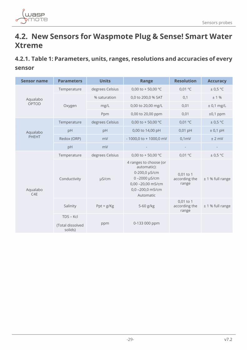
4.2. New Sensors for Waspmote Plug & Sense! Smart Water Xtreme
4.2.1. Table 1: Parameters, units, ranges, resolutions and accuracies of every sensor
Sensor name Parameters Units Range Resolution Accuracy
Aqualabo OPTOD
Temperature degrees Celsius 0,00 to + 50,00 ºC 0,01 ºC ± 0,5 °C
Oxygen
% saturation 0,0 to 200,0 % SAT 0,1 ± 1 %
mg/L 0,00 to 20,00 mg/L 0,01 ± 0,1 mg/L
Ppm 0,00 to 20,00 ppm 0,01 ±0,1 ppm
Aqualabo PHEHT
Temperature degrees Celsius 0,00 to + 50,00 ºC 0,01 ºC ± 0,5 °C
pH pH 0,00 to 14,00 pH 0,01 pH ± 0,1 pH
Redox (ORP) mV - 1000,0 to + 1000,0 mV 0,1mV ± 2 mV
pH mV - - -
Aqualabo C4E
Temperature degrees Celsius 0,00 to + 50,00 ºC 0,01 ºC ± 0,5 °C
Conductivity μS/cm
4 ranges to choose (or automatic):
0-200,0 μS/cm0 –2000 μS/cm
0,00 –20,00 mS/cm0,0 –200,0 mS/cm
Automatic
0,01 to 1 according the
range± 1 % full range
Salinity Ppt = g/Kg 5-60 g/kg0,01 to 1
according the range
± 1 % full range
TDS – Kcl
(Total dissolved solids)
ppm 0-133 000 ppm

-30- v7.2
Sensors probes
Sensor name Parameters Units Range Resolution Accuracy
Aqualabo NTU
Temperature degrees Celsius 0,00 to + 50,00 ºC 0,01 ºC ± 0,5 °C
Nephelometric
Turbidity
NTU
0-4000 NTU
4 ranges to choose for Parameters 1 and 2 (or
automatic):
- range 1: 0 / 50 NTU (FNU)
- range 2: 0 / 200 NTU (FNU)
- range 3: 0 / 1000 NTU (FNU)
- range 4: 0 / 4000 NTU (FNU)
-Automatic
0,01 to 1 NTU – mg/L
± < 5 % full range
Range 1: ±2,5NTU Range 2: ±10NTU
Range 3: ±50 NTU
Range 4: ±200NTU
FNU
(1 FNU = 1 NTU)
Same ranges than the previous parameter
SS
(Suspended Solids)
mg/L 0 to 4500 mg/L
Aqualabo CTZN
Temperature degrees Celsius 0,00 to + 50,00 ºC 0,01 ºC ± 0,5 °C
Conductivity mS/cm 0,0 –100,0 mS/cm 0,1 mS/cm
Check dependency
tables
Salinity Ppt = g/kg 5-60 g/kg 0,1 mS/cm
Conductivity not compensated
with temperature
mS/cm 0,0 –100,0 mS/cm 0,1 mS/cm
Aqualabo MES 5
Temperature degrees Celsius 0,00 to + 50,00 ºC 0,01 ºC ± 0,5 °C
Sludge blanket % 0-100 % 0.01 to 0.1 % 0,02
SS
(Suspended Solids)
g/L 0-50 g/L 0.01 g/L <10%
Turbidity FAU 0-400 FAU 0.01 to 1 FAU 0,05
Eureka Fluorometer:
Chlorophyll a - blue
Chlorophyll a - blue μg/l 0 to 500 μg/l
6 digits with maximum of two decimals
linearity of 0.99R²
Eureka Fluorometer:
Chlorophyll a - red
Chlorophyll a - red μg/l > 500 μg/l
6 digits with maximum of two decimals
linearity of 0.99R²
Eureka Fluorometer: Phycocyanin
(freshwater BGA)
Phycocyanin (freshwater BGA) ppb 0 to 40,000 ppb
6 digits with maximum of two decimals
linearity of 0.99R²
Eureka Fluorometer: Phycoerythrin (marine BGA)
Ammonium ppb 0 to 750 ppb6 digits with maximum of two decimals
linearity of 0.99R²

-31- v7.2
Sensors probes
Sensor name Parameters Units Range Resolution Accuracy
Eureka Fluorometer: CDOM/fDOM
CDOM/fDOM (Colored Dissolved
Organic Matter/ Fluorescent Dissolved
Organic Matter)
ppb 0 to 1250 or 0 to 5000 ppb
6 digits with maximum of two decimals
linearity of 0.99R²
Eureka Ion-selective
electrodes (ISE's): Ammonium
Ammonium mg/l 0 to 100 mg/l as nitrogen 0.1 5% or 2 mg/l
Eureka Ion-selective
electrodes (ISE's): Nitrate
Nitrate mg/l 0 to 100 mg/l as nitrogen 0.1 5% or 2 mg/l
Eureka Ion-selective
electrodes (ISE's): Chloride
Chloride mg/l 0 to 18,000 mg/l 0.1 5% or 2 mg/l
Eureka Ion-selective
electrodes (ISE's): Sodium
Sodium mg/l 0 to 20,000 mg/l 0.1 5% or 2 mg/l
Eureka Ion-selective
electrodes (ISE's): Calcium
Calcium mg/l 0 to 40,000 mg/l 0.1 5% or 2 mg/l

-32- v7.2
Sensors probes
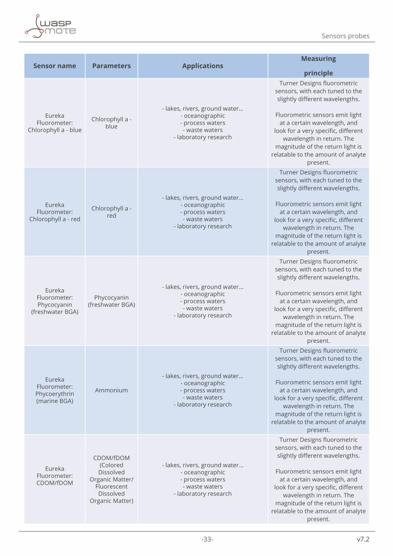
4.2.2. Table 2: Applications and measuring principles
Sensor name Parameters ApplicationsMeasuring
principle
Aqualabo OPTOD
Temperature - Industrial and municipal sewage treatment plants
- Wastewater management (nitrification and de-nitrification)
- Surface water monitoring - Fish farming, aquaculture - Drinking water monitoring
Optical measure by luminescence technologyOxygen
Aqualabo PHEHT
Temperature - Industrial and municipal sewage treatment plants
- Wastewater management (nitrification and de-nitrification)
- Surface water monitoring - Drinking water monitoring
ORP: Platinum electrode - Ag/AgCl reference
PH: plasticized PONSEL
PLASTOGEL®. Electrolyte – Ag/AgCl reference
pH
Redox (ORP)
pH
Aqualabo C4E
Temperature
- Industrial and municipal sewage treatment plants
- Wastewater management (nitrification and de-nitrification)*
- Surface water monitoring - Drinking water monitoring
Electrochemical conductivity sensor with 4 electrodes (2
graphite, 2 platinum)
Conductivity
Salinity
TDS – Kcl
(Total dissolved solids)
Aqualabo NTU
Temperature
- Urban wastewater treatment (inlet/ outlet controls)
- Sanitation network - Industrial effluent treatment
- Surface water monitoring - Drinking water
Nephelometry: Optical IR (850 nm) sensor based
on IR diffusion at 90 degrees
Nephelometric
Turbidity
SS
(Suspended Solids)
Aqualabo CTZN
Temperature
- Urban wastewater treatment - Industrial effluent treatment
- Surface water monitoring - Sea water
- Fish farming
Inductive conductivity sensor regulated in temperature
Conductivity
Salinity
Conductivity not compensated
with temperature
Aqualabo MES 5
Temperature - Urban Waste water treatment (Inlet/ sewage water (SS, Turbidity), Aeration basin
(SS), Outlet (Turbidity).
- Treatment of industrial effluents (Aeration b asin (SS)), Clarifier (Sludge blanket), Outlet
(Turbidity) - Sludge treatment (Centrifugation)
- Dredging site (turbidity)
Absorptometry: Optical IR (870 nm) sensor based on IR absorption at 180 degrees
Sludge blanket
SS
(Suspended Solids)
Turbidity
-33- v7.2
Sensors probes
Sensor name Parameters ApplicationsMeasuring
principle
Eureka Fluorometer:
Chlorophyll a - blue
Chlorophyll a - blue
- lakes, rivers, ground water... - oceanographic - process waters - waste waters
- laboratory research
Turner Designs fluorometric sensors, with each tuned to the slightly different wavelengths.
Fluorometric sensors emit light
at a certain wavelength, and look for a very specific, different
wavelength in return. The magnitude of the return light is
relatable to the amount of analyte present.
Eureka Fluorometer:
Chlorophyll a - red
Chlorophyll a - red
- lakes, rivers, ground water... - oceanographic - process waters - waste waters
- laboratory research
Turner Designs fluorometric sensors, with each tuned to the slightly different wavelengths.
Fluorometric sensors emit light
at a certain wavelength, and look for a very specific, different
wavelength in return. The magnitude of the return light is
relatable to the amount of analyte present.
Eureka Fluorometer: Phycocyanin
(freshwater BGA)
Phycocyanin (freshwater BGA)
- lakes, rivers, ground water... - oceanographic - process waters - waste waters
- laboratory research
Turner Designs fluorometric sensors, with each tuned to the slightly different wavelengths.
Fluorometric sensors emit light
at a certain wavelength, and look for a very specific, different
wavelength in return. The magnitude of the return light is
relatable to the amount of analyte present.
Eureka Fluorometer: Phycoerythrin (marine BGA)
Ammonium
- lakes, rivers, ground water... - oceanographic - process waters - waste waters
- laboratory research
Turner Designs fluorometric sensors, with each tuned to the slightly different wavelengths.
Fluorometric sensors emit light
at a certain wavelength, and look for a very specific, different
wavelength in return. The magnitude of the return light is
relatable to the amount of analyte present.
Eureka Fluorometer: CDOM/fDOM
CDOM/fDOM (Colored Dissolved
Organic Matter/ Fluorescent Dissolved
Organic Matter)
- lakes, rivers, ground water... - oceanographic - process waters - waste waters
- laboratory research
Turner Designs fluorometric sensors, with each tuned to the slightly different wavelengths.
Fluorometric sensors emit light
at a certain wavelength, and look for a very specific, different
wavelength in return. The magnitude of the return light is
relatable to the amount of analyte present.

-34- v7.2
Sensors probes
Sensor name Parameters ApplicationsMeasuring
principle
Eureka Ion-selective
electrodes (ISE's): Ammonium
Ammonium
- lakes, rivers, ground water... - oceanographic - process waters - waste waters
- laboratory research
Membrane that is selective for the analyte of ammonium.
The electrode’s filling solution contains a salt of the analyte, and the difference between that salt’s concentration and
the analyte concentration in the measured water produces a
charge separation. That charge separation is measured, relative to the reference electrode, as a
voltage that changes predictably with changes in the analyte concentration in the water adjacent the membrane.
Eureka Ion-selective
electrodes (ISE's): Nitrate
Nitrate
- lakes, rivers, ground water... - oceanographic - process waters - waste waters
- laboratory research
Membrane that is selective for the analyte of nitrate.
The electrode’s filling solution contains a salt of the analyte, and the difference between that salt’s concentration and
the analyte concentration in the measured water produces a
charge separation. That charge separation is measured, relative to the reference electrode, as a
voltage that changes predictably with changes in the analyte concentration in the water adjacent the membrane.
Eureka Ion-selective
electrodes (ISE's): Chloride
Chloride
- lakes, rivers, ground water... - oceanographic - process waters - waste waters
- laboratory research
Membrane that is selective for the analyte of chloride.
The electrode’s filling solution contains a salt of the analyte, and the difference between that salt’s concentration and
the analyte concentration in the measured water produces a
charge separation. That charge separation is measured, relative to the reference electrode, as a
voltage that changes predictably with changes in the analyte concentration in the water adjacent the membrane.

-35- v7.2
Sensors probes
Sensor name Parameters ApplicationsMeasuring
principle
Eureka Ion-selective
electrodes (ISE's): Sodium
Sodium
- lakes, rivers, ground water... - oceanographic - process waters - waste waters
- laboratory research
Membrane that is selective for the analyte of sodium.
The electrode’s filling solution contains a salt of the analyte, and the difference between that salt’s concentration and
the analyte concentration in the measured water produces a
charge separation. That charge separation is measured, relative to the reference electrode, as a
voltage that changes predictably with changes in the analyte concentration in the water adjacent the membrane.
Eureka Ion-selective
electrodes (ISE's): Calcium
Calcium
- lakes, rivers, ground water... - oceanographic - process waters - waste waters
- laboratory research
Membrane that is selective for the analyte of calcium.
The electrode’s filling solution contains a salt of the analyte, and the difference between that salt’s concentration and
the analyte concentration in the measured water produces a
charge separation. That charge separation is measured, relative to the reference electrode, as a
voltage that changes predictably with changes in the analyte concentration in the water adjacent the membrane.

-36- v7.2
Sensors probes
4.3. Optical dissolved oxygen and temperature OPTOD sen-sor probeThe Optical dissolved oxygen and temperature OPTOD sensor probe, based on a luminescent optical technology, meets the demands of long term smart water applications. The OPTOD sensor probe measures accurately without oxygen consumption, especially with very low concentrations and very weak water flow. It is designed in a compact, robust and light probe with a stainless steel body.
It is often recommended to use an atmospheric pressure sensor together with the OPTOD sensor probe, due to the degree of solubility of oxygen in water is dependant on the atmospheric pressure. Moreover, the salinity is also related.
Figure: Optical dissolved oxygen and temperature OPTOD sensor probe
4.3.1. Specifications
Dissolved oxygen sensor:
• Technology: Optical luminescence • Ranges:
- 0 to 20.00 mg/L - 0 to 20.00 ppm - 0 – 200%
• Resolution: 0.01 • Accuracy:
- ±0.1 mg/L - ±0.1 ppm - ±1%
• Response time: 90% of the value in less than 60 seconds • Frequency of recommended measure: > 5 s • Cross sensitivity: Organic solvents, such as acetone, toluene, chloroform or methylene chloride. Chlorine
gas.

-37- v7.2
Sensors probes
Temperature sensor:
• Technology: NTC • Range: 0 °C to +50 °C • Resolution: 0.01 °C • Accuracy: ±0.5 °C • Response time: < 5 s
Common:
• Water flow is not necessary • Default cable length: 15 m • Maximum pressure: 5 bars • Body material: Stainless steel (titanium option available on demand for sea water applications) • IP classification: IP68 • Storage temperature: -10 °C to +60 °C
Figure: Sensor probe parts: (1) membrane cap (consumable), (2) membrane screw and seal, (3) sensor body
Figure: Dimensions of the OPTOD sensor probe
4.3.2. Measurement process

-38- v7.2
Sensors probes
The OPTOD sensor probe provides a digital signal using the SDI-12 protocol.
Reading code:
{ // 1. Declare an object for the sensor Aqualabo_OPTOD mySensor(XTR_SOCKET_A); // 2. Turn ON the sensor mySensor.ON(); // 3. Read the sensor. Values stored in class variables // Check complete code example for details mySensor.read(); // 4. Turn off the sensor mySensor.OFF();}
During the sensor measurement, there is a small stabilization time of a few seconds, so it is recommendable to wait until the values remains stable over time.
A complete example code for reading this sensor probe can be found in the following link:
http://www.libelium.com/development/waspmote/examples/sw-xtr-06-optod-sensor-reading
4.3.3. Socket
Connect the OPTOD sensor probe to Plug & Sense! Smart Water Xtreme in any of the sockets shown in the image below.
Figure: Available sockets for the OPTOD sensor probe

-39- v7.2
Sensors probes
4.3.4. Maintenance
4.3.4.1. Calibration
By default, the sensor probe is factory-calibrated, therefore calibration may not be needed for the first usage. However, it is not recommended unless it is periodically required by regulatory agencies or the membrane is replaced. Nevertheless, prior to carry out the sensor probe calibration, please bear in mind the next comments:
• The OPTOD sensor probe comes dry and it needs to be rehydrated during 12 hours in tap water before taking any measure.
• It is important that the sensor and the buffer solutions have the same temperature, so before starting the calibration process leave all the necessary elements in the same temperature conditions. Besides, wait for sensor temperature stabilization once it has been immersed.
• During the sensor measurement, there is a small stabilization time of some seconds, so please wait until the values remains stable over time.
• The buffer solution bottles must be closed properly after the usage, to prevent deviations on the default values.
• The measured value for dissolved oxygen is automatically compensated with the temperature, air pressure, and salinity (salt content).
• It is recommended to replace the membrane every 2 years.
Note: The sensor membrane must not be inside the dissolved oxygen buffer solution more than an hour. Otherwise it will be damaged and measures will be incorrect. Besides, some chemicals can damage the membrane. Contact our Sales department through the next link if you require more information: http://www.libelium.com/contact.
First of all, ensure that all necessary elements are present. It is important that if a calibration process is started, it should be completed to save the results in the sensor internal memory. Do not abandon the calibration process and always follow the given steps and guidelines to avoid a sensor misconfiguration. If the process needs to be repeated or abandoned, always type the ‘Q’ command to exit the calibration procedure.
Libelium provides the necessary standard buffer solution to calibrate the Smart Water Xtreme sensor probes. Refer to the calibration solution section for more information.
Figure: Necessary elements for the OPTOD sensor probe calibration

-40- v7.2
Sensors probes
The sensor calibration can be done only on socket E. Owing to that, connect the sensor probe to socket E of the Plug & Sense! Smart Water Xtreme unit to calibrate the sensor, as shown in the image below. Do not use any other Plug & Sense! socket to calibrate a sensor. It will not work.
Figure: Connecting the sensor to the calibration socket
The OPTOD sensor probe allows to calibrate temperature and dissolved oxygen. Please read below the necessary steps to calibrate each parameter.
Temperature calibration
The temperature calibration process is the same for all Plug & Sense! Smart Water Xtreme sensor probes.
It is recommended to calibrate in 2 points. The user can choose any 2 points inside the sensor range, but it is recommended to use 0 ºC (can be achieved using water plus ice) and 25 ºC. Moreover, it is necessary to use a external thermometer as a reference.
Now, upload the temperature calibration example for the corresponding sensor probe. The code uses the serial monitor to assist the user with messages and recommendations. The main steps are described below, but the full details are provided in the code.

-41- v7.2
Sensors probes
Step 1: The pH calibration process allows 2 or 3 calibration points. Select the desired points.
Step 2: Type the first calibration point (offset) on the serial monitor and press enter.
Figure: Type the first calibration point on the serial monitor

-42- v7.2
Sensors probes
Step 3: Pour tap water in a clean baker. Immerse the sensor in water at your selected offset. Remove the black protection cap before immersing the sensor in the buffer solution. Wait until values are stabilized over time and type ‘N’ to continue. Ensure there are not any bubbles on the sensor membrane to avoid measure disturbances. The stabilization time for pH measures could take up to 20 minutes.
Note: Do not discard the black protection cap and keep it for the future. It will be useful if the sensor needs to be stored for a large period.
Figure: Immersing the sensor inside the calibration buffer solution

-43- v7.2
Sensors probes
Step 4: Remove the sensor from the buffer solution and clean it carefully as previously described.
Step 5: Type the second calibration point (slope) on the serial monitor and press enter.
Figure: Type the second calibration point on the serial monitor
Step 6: Immerse the sensor in water at your selected slope. Wait until values are stabilized over time and type ‘N’ to continue.

-44- v7.2
Sensors probes
Step 7: Save calibration data into the sensor by typing operators name and date of calibration. Then, the sensor values will be printed on the screen to check if the measures are done correctly.
Figure: Save the calibration data
Dissolved Oxygen calibration
The OPTOD sensor probe allows to calibrate the dissolved oxygen parameter with one or two calibration points. It is recommended that temperature and air pressure remain constant during the calibration process.
Upload the dissolved oxygen calibration example for the OPTOD sensor probe. The code uses the serial monitor to assist the user with messages and recommendations. The main steps are described below, but the full details are provided in the code.
Two points calibration:
With this method, a 0% concentration (offset) and a 100% concentration (slope) are measured, offering great accuracy for small concentrations.
Step 1: Type the desired number of calibration points on the serial monitor and press enter. After that, the first calibration point is automatically set to zero.
Step 2: Pour enough buffer solution in a clean baker to cover the sensor head. Immerse the sensor in the 0% standard buffer solution. Remove the black protection cap before immersing the sensor in the buffer solution. Remove the solution with the sensor so that the oxygen saturation decreases more quickly. Ensure there are not any bubbles on the sensor membrane to avoid measure disturbances. Wait until values are stabilized over time and type ‘N’ to continue.

-45- v7.2
Sensors probes
Figure: Waiting for stabilization
Note: The sensor membrane must not be in contact with the 0% buffer solution more than an hour, so minimize the contacting time. Otherwise the membrane will be damaged permanently and incorrect measurements will be obtained.

-46- v7.2
Sensors probes
Figure: Immersing the sensor inside the calibration buffer solution
Step 3: Remove the sensor from the buffer solution and clean it carefully as previously described.
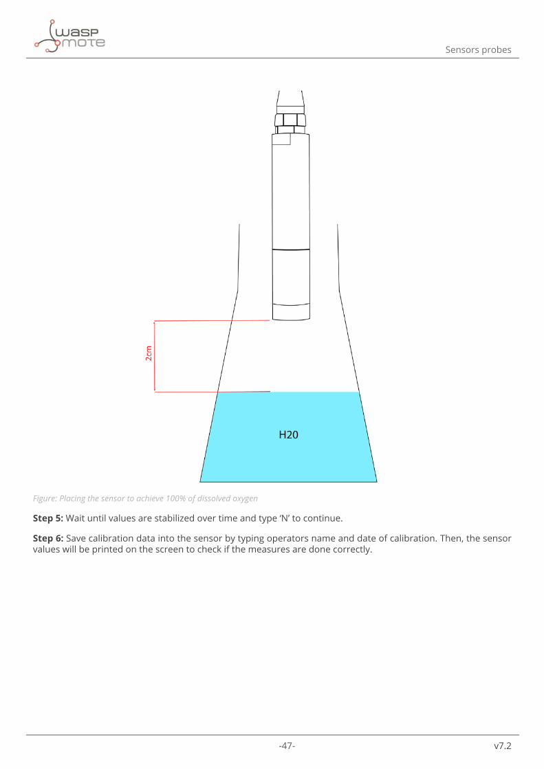
Step 4: Now the second calibration point of 100% can be achieved by placing the sensor approximately 2 centimeters above the water surface and keeping the membrane without water drops that could disturb the measure. Remember to shake the water in order to introduce the maximum amount of oxygen inside water. The next picture shows a diagram.
-47- v7.2
Sensors probes
Figure: Placing the sensor to achieve 100% of dissolved oxygen
Step 5: Wait until values are stabilized over time and type ‘N’ to continue.
Step 6: Save calibration data into the sensor by typing operators name and date of calibration. Then, the sensor values will be printed on the screen to check if the measures are done correctly.

-48- v7.2
Sensors probes
Figure: Save the calibration data
One point calibration:
It consist of measuring the 100% of dissolved oxygen as describd previously. The one point calibration process is valid for most situations, especially on the field. Remember that any water drop present in the membrane could distort the measures.

-49- v7.2
Sensors probes
4.3.4.2. Cleaning the sensor
The OPTOD sensor probe is designed for low maintenance. However, it needs to be cleaned periodically to remove the possible fouling or other biologic material that could appear in the sensor.
Use tap water, soap to rinse the sensor carefully and a soft towel to dry it and remove the biologic material.
The presence of biofilm in the sensor membrane can introduce measuring errors. Use a soft sponge if needed.
Figure: Cleaning de sensor
It is not necessary to remove the membrane for sensor cleaning.
Finally, if the sensor is not going to be used during a large period, it is important to clean the sensor prior to storing it. Remember to place the protection cap together with a moisture absorbent element (like a piece of cotton).
4.3.5. Installation
It is important to think about a few aspects before installing the sensor on the field:
• The sensor body should be easily accessible for cleaning, regular maintenance and calibration. • The sensor body must be firmly fastened to avoid sensor swing and possible collisions with the surrounding
objects that can damage the sensor. • If the sensor is installed totally immersed, it should be fastened from the body and not from the cable. The
cable is not designed to hold the sensor and it could be damaged. • Avoid bubbles around the sensor. • For those users interested in measuring directly inside pipes, there are pipe segments with a protected
measurement point. As an optional accessory for this sensor, Libelium offers a pipe mounting adapter (available in PVC and in stainless steel) which can be connected to those special pipe segments.

-50- v7.2
Sensors probes
Figure: Typical installation on a pipe
Figure: Another typical installation on a lake
If the sensor is used in a hard environment where animals, solids or other environmental elements can damage the sensor, a protection strainer is available as an accessory of extra protection. Contact our Sales department through the next link if you require more information: http://www.libelium.com/contact.

-51- v7.2
Sensors probes
Figure: Protection strainer accessory
A complete sensor manual can be found on the manufacturer’s website.
4.3.6. Application examples
• Industrial and public sewage treatment plants • Wastewater management (nitrification and de-nitrification) • Surface water monitoring • Fish farming, aquaculture • Drinking water monitoring
4.3.7. Calibration report
Together with this sensor we provide a factory calibration report in which the manufacturer ensures that the sensor has passed a calibration procedure with traceability.

-52- v7.2
Sensors probes
4.4. pH, ORP and temperature PHEHT sensor probeThe pH, ORP and temperature PHEHT sensor probe combines 3 sensors in one probe, which has been designed to measure under hard conditions like pure snow melting water with low conductivity, lakes, rivers, sea water or even waste waters with high conductivity values.
The PHEHT sensor probe is based on measuring the difference of potential between a reference electrode and a measure electrode. It includes a long-life reference which increases its lifetime and also it has a high interference immunity. The ORP sensor is thought for normal or modest accuracy applications (fine accuracy is not provided).
Besides, the sensor has a temperature compensation for pH measures carried out by its internal NTC temperature sensor.
Note: Oxidation reduction potential (ORP) and Reduction / Oxidation (Redox) are equivalent terms.
Figure: pH, ORP and temperature PHEHT sensor probe

-53- v7.2
Sensors probes
4.4.1. Specifications
pH sensor:
• Technology: Combined electrode • Measurement range: 0~14 pH • Resolution: 0.01 pH • Accuracy: ±0.1 pH
ORP sensor:
• Technology: Combined electrode • Measurement range: -1000 to +1000 mV • Resolution: 0.1 mV • Accuracy: ±2 mV
Temperature sensor:
• Technology: NTC • Range: 0 °C to +50 °C • Resolution: 0.01 °C • Accuracy: ±0.5 °C • Response time: < 5 s
Common:
• Default cable length: 15 m • Maximum pressure: 5 bars • IP classification: IP68 • Storage temperature: 0 °C to +60 °C
Figure: Sensor parts: (1) protection strainer, (2) cartridge (consumable part), (3) clamp, (4) sensor body

-54- v7.2
Sensors probes
Figure: Dimensions of the PHEHT sensor probe
4.4.2. Measurement process
The PHEHT sensor provides a digital signal using the SDI-12 protocol.
Reading code:
{ // 1. Declare an object for the sensor Aqualabo_PHEHT mySensor(XTR_SOCKET_A); // 2. Turn ON the sensor mySensor.ON(); // 3. Read the sensor. Values stored in class variables // Check complete code example for details mySensor.read(); // 4. Turn off the sensor mySensor.OFF();}
During the sensor measurement, there is a small stabilization time of a few seconds, so it is recommendable to wait until the values remains stable over time.
You can find a complete example code for reading this sensor probe in the following link:
http://www.libelium.com/development/waspmote/examples/sw-xtr-10-pheht-sensor-reading

-55- v7.2
Sensors probes
4.4.3. Socket
Connect the PHEHT sensor probe to Plug & Sense! Smart Water Xtreme in any of the sockets shown in the image below.
Figure: Available sockets for the PHEHT sensor probe
4.4.4. Maintenance
4.4.4.1. Calibration
By default, the sensor is factory-calibrated, therefore calibration may not be needed for the first usage. Nevertheless, prior to carry out the sensor calibration, please bear in mind the next comments:
• The PHEHT sensor probe comes dry and it needs to be rehydrated during 12 hours in a standard pH4 buffer solution before taking any measure.
• During the calibration process the temperature is not compensated, therefore it must be taken into account. On the contrary, during normal measures the temperature is compensated.
• It is important that the sensor and the buffer solutions have the same temperature, so before starting the calibration process leave all the necessary elements in the same temperature conditions. Besides, wait for sensor temperature stabilization once it has been immersed.
• During the sensor measurement, there is a small stabilization time of a few seconds, so please wait until the values remains stable over time.
• The calibration must be done every 15 days to get a reasonable accuracy in the measurements. However, depending the application, the time between two calibrations would vary. It is highly recommended to do a test as close as possible to the conditions of the final application to check the sensor drift over time. This will allow to adjust the calibration periods according to the required accuracy.
• The buffer solution bottles must be closed properly after the usage, to prevent deviations on the default values.

-56- v7.2
Sensors probes
Note: Do not place the sensor in distilled water. The sensor will be seriously damaged. Besides, the glass electrode is vulnerable to chemicals like organic solvents, acids and strong bases, peroxide and hydrocarbons.
First of all, ensure that all necessary elements are present. It is important that if a calibration process is started, it should be completed to save the results in the sensor internal memory. Do not abandon the calibration process and always follow the given steps and guidelines to avoid a sensor misconfiguration. If the process needs to be repeated or abandoned, always type the ‘D’ command to exit the calibration procedure.
Libelium provides the necessary standard buffer solution to calibrate the Smart Water Xtreme sensor probes. Refer to the calibration solution section for more information.
Figure: Necessary elements for the PHEHT sensor probe calibration
The sensor calibration can be done only on socket E. Owing to that, connect the sensor probe to socket E of the Plug & Sense! Smart Water Xtreme unit to calibrate the sensor, as shown in the image below. Do not use any other Plug & Sense! socket to calibrate a sensor. It will not work.

-57- v7.2
Sensors probes
Figure: Connecting the sensor to the calibration socket
The PHEHT sensor probe allows to calibrate temperature, pH and also check the ORP values. Please read below the necessary steps to calibrate each parameter.
Temperature calibration
The temperature calibration process is the same for all Plug & Sense! Smart Water Xtreme sensor probes. Refer to the previously described temperature calibration section of the OPTOD sensor probe for details.
pH calibration
In the same way as temperature, a two-point calibration is recommended for pH sensor of the PHEHT sensor probe. The offset and slope points can be achieved with the standard buffer solutions provided by Libelium. This calibration method offers the greatest possible level of accuracy and is particularly recommended.
In addition, it is recommended to calibrate first with pH 7 buffer solution and then move to pH 4 or pH 10 depending the range of the measures of the application.
It is important to remark that during the pH calibration process the temperature is not compensated and the pH value for standard buffer solution varies with the temperature, so it is important to carry out the calibration at 25 ºC. If it is not possible, take into account the next tables for temperature compensation. For example, if the buffer solution temperature is 20 ºC, the pH value will be 7.03 instead of 7.01.
Temperature (Celsius) pH value for standard buffer solution
pH value for standard buffer solution
0 7.13 4.015 7.10 4.00
10 7.07 4.0015 7.04 4.0020 7.03 4.0025 7.01 4.0130 7.00 4.0235 6.99 4.0340 6.98 4.0445 6.98 4.05
Figure: Temperature compensation table for standard buffer solutions
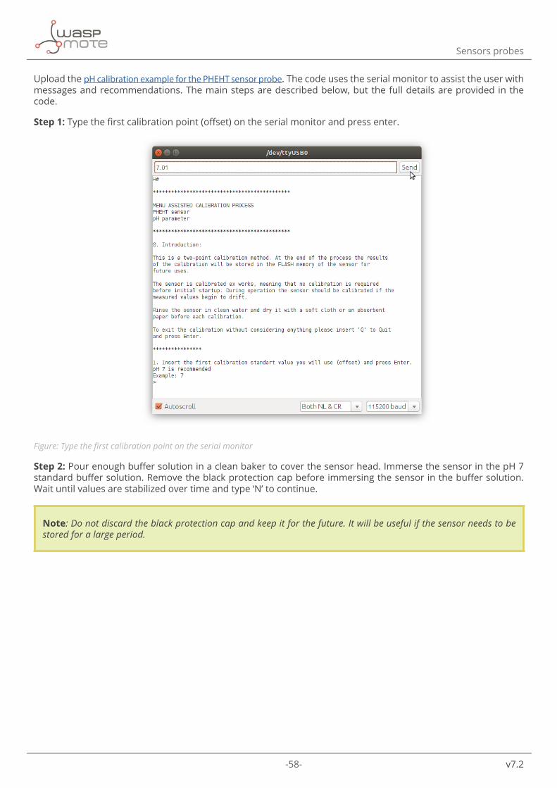
-58- v7.2
Sensors probes
Upload the pH calibration example for the PHEHT sensor probe. The code uses the serial monitor to assist the user with messages and recommendations. The main steps are described below, but the full details are provided in the code.
Step 1: Type the first calibration point (offset) on the serial monitor and press enter.
Figure: Type the first calibration point on the serial monitor
Step 2: Pour enough buffer solution in a clean baker to cover the sensor head. Immerse the sensor in the pH 7 standard buffer solution. Remove the black protection cap before immersing the sensor in the buffer solution. Wait until values are stabilized over time and type ‘N’ to continue.
Note: Do not discard the black protection cap and keep it for the future. It will be useful if the sensor needs to be stored for a large period.

-59- v7.2
Sensors probes
Figure: Immersing the sensor inside the calibration buffer solution
Step 3: Remove the sensor from the buffer solution and clean it carefully as previously described.
Step 4: Type the second calibration point (slope) on the serial monitor and press enter.

-60- v7.2
Sensors probes
Figure: Type the second calibration point on the serial monitor
Step 5: Pour enough buffer solution in a clean baker to cover the sensor head. Immerse the sensor inside the desired standard buffer solution. Wait until values are stabilized over time and type ‘N’ to continue.
Step 6: Save calibration data into the sensor by typing operators name and date of calibration. Then, the sensor values will be printed on the screen to check if the measures are done correctly.
Figure: Save the calibration data

-61- v7.2
Sensors probes
ORP calibration
Regarding the ORP calibration, it is done using a two-point calibration. The offset will be the zero value exposing the sensor in the air and the slope will be an ORP standard buffer solution (225 mV).
Upload the ORP calibration example for the PHEHT sensor probe. The code uses the serial monitor to assist the user with messages and recommendations. The main steps are described below, but the full details are provided in the code.
Step 1: The first calibration point (offset) is set to zero and it cannot be changed. So keep the sensor exposed to the air and wait till measure stabilization over time. Then type ‘N’ to continue. Remember to remove the black protection cap.
Note: Do not discard the black protection cap and keep it for the future. It will be useful if the sensor needs to be stored for a large period.
Step 2: Type the second calibration point (slope) on the serial monitor and press enter.
Step 3: Pour enough buffer solution in a clean baker to cover the sensor head. Immerse the sensor inside the ORP standard buffer solution. Wait until values are stabilized over time and type ‘N’ to continue.
Figure: Immersing the sensor inside the calibration buffer solution
Step 4: Save calibration data into the sensor by typing operators name and date of calibration. Then, the sensor values will be printed on the screen to check if the measures are done correctly.

-62- v7.2
Sensors probes
Figure: Save the calibration data
Step 5: Remove the sensor from the buffer solution and clean it carefully as described in the next section.

-63- v7.2
Sensors probes
4.4.4.2. Cleaning the sensor
The PHEHT sensor probe needs to be cleaned periodically to remove the possible fouling or other biologic material that could appear in the sensor.
Before cleaning the sensor, please keep in mind that the crystal electrode used for pH measurement is very fragile. Use tap water, soap to rinse the sensor carefully and a soft towel to dry it and remove the biologic material. Avoid using absorbent paper because the glass electrode is extremely vulnerable to frictions. Moreover, if the ORP sensor of the PHEHT sensor probe is still dirty, use a soft and fine sandpaper to clean the metallic part.
Figure: Cleaning the sensor
The presence of biofilm in the sensor electrodes can introduce measuring errors.
On top of that, the cartridge could be replaced if it is damaged for some reason. Contact Libelium for more information.
Finally, if the sensor is not going to be used during a large period, it is important to clean the sensor prior to storing it. Remember to place the protection cap together with a moisture absorbent element (like a piece of cotton) and also to fill the cap with the storage solution for PHEHT probe. This will avoid the electrode to become deteriorated. The storage solution is sold as an accessory for the sensor.
4.4.5. Installation
It is important to think about a few aspects before installing the sensor on the field:
• The sensor body should be easily accessible for cleaning, regular maintenance and calibration. • The sensor body must be firmly fastened to avoid sensor swing and possible collisions with the surrounding
objects that can damage the sensor. • If the sensor is installed totally immersed, it should be fastened from the body and not from the cable. The
cable is not designed to hold the sensor and it could be damaged. • Avoid bubbles around the sensor. • For those users interested in measuring directly inside pipes, there are pipe segments with a protected
measurement point. As an optional accessory for this sensor, Libelium offers a pipe mounting adapter (available in PVC and in stainless steel) which can be connected to those special pipe segments.

-64- v7.2
Sensors probes
Figure: Typical installation on a pipe
Figure: Another Typical installation on a lake
If the sensor is used in a hard environment where animals, solids or other environmental elements can damage the sensor, a protection strainer is available as an accessory of extra protection. Contact our Sales department through the next link if you require more information: http://www.libelium.com/contact.

-65- v7.2
Sensors probes
Figure: Protection strainer accessory
A complete sensor manual can be found on the manufacturer’s website.
4.4.6. Application examples
• Industrial and public sewage treatment plants • Wastewater management (nitrification and de-nitrification) • Surface water monitoring • Drinking water monitoring
4.4.7. Calibration report
Together with this sensor we provide a factory calibration report in which the manufacturer ensures that the sensor has passed a calibration procedure with traceability.

-66- v7.2
Sensors probes
4.5. Conductivity, salinity and temperature C4E sensor pro-beThe Conductivity, salinity and temperature C4E sensor probe uses a four-electrode technology that offers a great accuracy with low maintenance. For this, the electrolytes do not need to be replaced. Besides, calibration intervals are long due to the low drift of its measures.
The conductivity values are internally compensated with the temperature provided by the embedded sensor. Moreover, it does not consume oxygen and therefore does not require a minimum inflow.
Figure: Conductivity, salinity and temperature C4E sensor probe
4.5.1. Specifications
Conductivity sensor:
• Technology: 4 electrode (2 graphite, 2 platinum) • Ranges:
- 0 - 200 µS/cm - 0 - 2 mS/cm - 0 - 20 mS/cm - 0 - 200 mS/cm
• Resolution: 0.01 to 1 according the range • Accuracy: ±1% of the full range • Measurement range (salinity): 5 - 60 g/kg • Measurement range (TDS - Kcl): 0 - 133 000 ppm

-67- v7.2
Sensors probes
Temperature sensor:
• Technology: NTC • Range: 0 °C to +50 °C • Resolution: 0.01 °C • Accuracy: ±0.5 °C • Response time: < 5 s
Common:
• Default cable length: 15 m • Maximum pressure: 5 bars • Body material: PVC • IP classification: IP68 • Storage temperature: 0 °C to +60 °C
Figure: Sensor parts: (1) temperature sensor, (2) head with 4 electrodes, (3) sensor body
Figure: Dimensions of the C4E sensor probe

-68- v7.2
Sensors probes
4.5.2. Measurement process
The C4E sensor provides a digital signal using the SDI-12 protocol.
Reading code:
{ // 1. Declare an object for the sensor Aqualabo_C4E mySensor(XTR_SOCKET_A); // 2. Turn ON the sensor mySensor.ON(); // 3. Read the sensor. Values stored in class variables // Check complete code example for details mySensor.read(); // 4. Turn off the sensor mySensor.OFF();}
During the sensor measurement, there is a small stabilization time of a few seconds, so it is recommendable to wait until the values remains stable over time.
A complete example code for reading this sensor probe can be found in the following link:
http://www.libelium.com/development/waspmote/examples/sw-xtr-15-c4e-sensor-reading
4.5.3. Socket
Connect the C4E sensor probe to Plug & Sense! Smart Water Xtreme in any of the sockets shown in the image below.
Figure: Available sockets for the C4E sensor probe
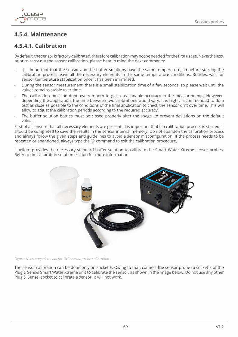
-69- v7.2
Sensors probes
4.5.4. Maintenance
4.5.4.1. Calibration
By default, the sensor is factory-calibrated, therefore calibration may not be needed for the first usage. Nevertheless, prior to carry out the sensor calibration, please bear in mind the next comments:
• It is important that the sensor and the buffer solutions have the same temperature, so before starting the calibration process leave all the necessary elements in the same temperature conditions. Besides, wait for sensor temperature stabilization once it has been immersed.
• During the sensor measurement, there is a small stabilization time of a few seconds, so please wait until the values remains stable over time.
• The calibration must be done every month to get a reasonable accuracy in the measurements. However, depending the application, the time between two calibrations would vary. It is highly recommended to do a test as close as possible to the conditions of the final application to check the sensor drift over time. This will allow to adjust the calibration periods according to the required accuracy.
• The buffer solution bottles must be closed properly after the usage, to prevent deviations on the default values.
First of all, ensure that all necessary elements are present. It is important that if a calibration process is started, it should be completed to save the results in the sensor internal memory. Do not abandon the calibration process and always follow the given steps and guidelines to avoid a sensor misconfiguration. If the process needs to be repeated or abandoned, always type the ‘Q’ command to exit the calibration procedure.
Libelium provides the necessary standard buffer solution to calibrate the Smart Water Xtreme sensor probes. Refer to the calibration solution section for more information.
Figure: Necessary elements for C4E sensor probe calibration
The sensor calibration can be done only on socket E. Owing to that, connect the sensor probe to socket E of the Plug & Sense! Smart Water Xtreme unit to calibrate the sensor, as shown in the image below. Do not use any other Plug & Sense! socket to calibrate a sensor. It will not work.

-70- v7.2
Sensors probes
Figure: Connecting the sensor to the calibration socket
The C4E sensor probe allows to calibrate temperature and conductivity. Please read below the necessary steps to calibrate each parameter.
Temperature calibration
The temperature calibration process is the same for all Plug & Sense! Smart Water Xtreme sensor probes. Refer to the previously described temperature calibration section of the OPTOD sensor probe for details.
Conductivity calibration
The conductivity calibration is based in a two-point calibration process. On top of that, the user should know the expected conductivity and salinity values of the final application in order to decide which buffer solutions are the best by choosing the closest values.
There are 3 different Calibration kits for Conductivity: K=0.1, K=1; K=10. The K factor is related to the salinity of the water we want to measure. Each calibration kit takes 2 solutions:
• K=0.1 - around µS 84 - around µS 1400
• K=1 - around µS 12000 - around µS 80000
• K=10 - around µS 12000 - around µS 150000
Note: The concentration value may vary in each batch with respect to the value shown above, due to the nature of the manufacturing process. That is why we wrote “around”. The sticker in each bottle indicates the exact value. Please notice that the software implemented for this calibration procedure is flexible, so it is valid for any concentration values.

-71- v7.2
Sensors probes
In the next table we see the typical conductivity depending on the kind of water we want to monitor:
Table of aqueous conductivitiesSolution µS/cm mS/cm ppm
Totally pure water 0.055 - -Typical DI water 0.1 - -Distilled water 0.5 - -
Domestic "tap" water 500-800 0.5-0.8 250-400Potable water (max) 1055 1.055 528
Sea water 50000 - 60000 56 28000
It can be seen that the relation between conductivity and dissolved solids is approximately:
2 µS/cm = 1 ppm (which is the same as 1 mg/l)
Upload the conductivity calibration example for the C4E sensor probe. The code uses the serial monitor to assist the user with messages and recommendations. The main steps are described below, but the full details are provided in the code.
Step 1: Select the desired sensor probe range according to the expected conductivity to be measured.
Step 2: Type the first calibration point (offset) on the serial monitor and press enter. Normally it is set to zero (sensor exposed to air). So keep the sensor exposed to the air and wait till measure stabilization over time. Then type ‘N’ to continue. Remember to remove the black protection cap.
Figure: Type the first calibration point on the serial monitor

-72- v7.2
Sensors probes
Step 3: Type the second calibration point (slope) on the serial monitor and press enter.
Figure: Type the second calibration point on the serial monitor
Step 4: Pour enough buffer solution in a clean baker to cover the sensor head. Immerse the sensor inside the chosen conductivity standard buffer solution. Wait until values are stabilized over time and type ‘N’ to continue.
Figure: Immersing the sensor inside the calibration buffer solution

-73- v7.2
Sensors probes
Step 4: Save calibration data into the sensor by typing operators name and date of calibration. Then, the sensor values will be printed on the screen to check if the measures are done correctly.
Figure: Save the calibration data
Step 5: Remove the sensor from the buffer solution and clean it carefully as described below.

-74- v7.2
Sensors probes
4.5.4.2. Cleaning the sensor
The C4E sensor probe needs to be cleaned periodically to remove the possible fouling or other biologic material that could appear in the sensor. The presence of biofilm in the sensor electrodes can introduce measuring errors.
Use tap water, soap to rinse the sensor carefully and a soft towel to dry it and remove the biologic material. If the biofilm persist on the electrodes, use an abrasive strip trough the sensor head slot to clean the electrodes under a stream of running water.
Figure: Cleaning the sensor
Finally, if the sensor is not going to be used during a large period, it is important to clean the sensor prior to storing it. Remember to place the protection cap together with a moisture absorbent element (like a piece of cotton).
4.5.5. Installation
It is important to think about a few aspects before installing the sensor on the field:
• The sensor body should be easily accessible for cleaning, regular maintenance and calibration. • The sensor body must be firmly fastened to avoid sensor swing and possible collisions with the surrounding
objects that can damage the sensor. • If the sensor is installed totally immersed, it should be fastened from the body and not from the cable. The
cable is not designed to hold the sensor and it could be damaged. • Avoid bubbles around the sensor. • For those users interested in measuring directly inside pipes, there are pipe segments with a protected
measurement point. As an optional accessory for this sensor, Libelium offers a pipe mounting adapter (available in PVC and in stainless steel) which can be connected to those special pipe segments.

-75- v7.2
Sensors probes
Figure: Typical installation on a pipe
Figure: Another Typical installation on a lake
If the sensor is used in a hard environment where animals, solids or other environmental elements can damage the sensor, a protection strainer is available as an accessory of extra protection. Contact our Sales department through the next link if you require more information: http://www.libelium.com/contact.
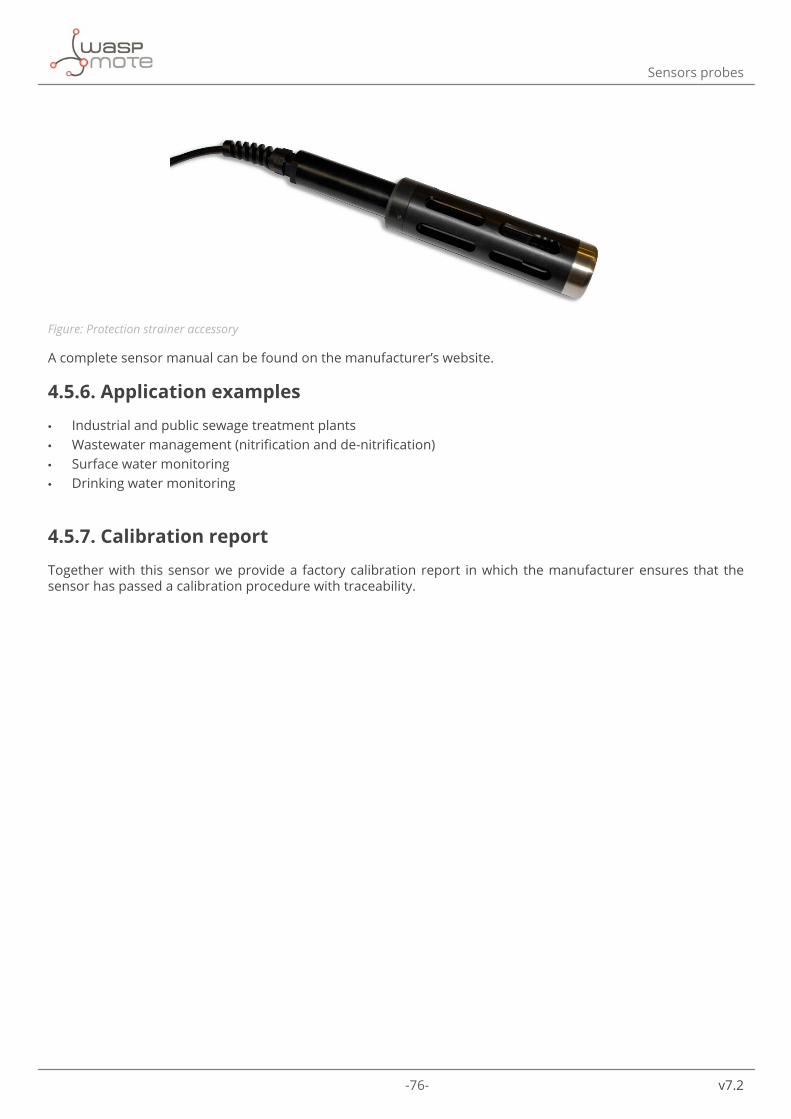
-76- v7.2
Sensors probes
Figure: Protection strainer accessory
A complete sensor manual can be found on the manufacturer’s website.
4.5.6. Application examples
• Industrial and public sewage treatment plants • Wastewater management (nitrification and de-nitrification) • Surface water monitoring • Drinking water monitoring
4.5.7. Calibration report
Together with this sensor we provide a factory calibration report in which the manufacturer ensures that the sensor has passed a calibration procedure with traceability.

-77- v7.2
Sensors probes
4.6. Inductive conductivity, salinity and temperature CTZN sensor probeThe Inductive conductivity, salinity and temperature CTZN sensor probe has a ring-type coil to measure the conductivity. This technology allows the sensor to avoid biofilm interferences, increasing the time between calibration periods and even avoiding most of the maintenance tasks.
In addition to conductivity, the CTZN sensor probe is able to measure salinity and temperature, all included in a compact and robust probe suitable for the most typical applications.
Figure: Inductive conductivity, salinity and temperature CTZN sensor probe
4.6.1. Specifications
Conductivity sensor:
• Technology: Inductive coil • Ranges: 0 – 100 mS/cm • Resolution: 0.1 • Measurement range (salinity): 5 - 60 g/kg • Working temperature: 0 to 50 °C • Response time: 90% of the value in less than 30 seconds
Temperature sensor:
• Technology: NTC • Range: 0 °C to +50 °C • Resolution: 0.01 °C • Accuracy: ±0.5 °C

-78- v7.2
Sensors probes
Common:
• Default cable length: 15 m • Maximum pressure: 5 bars • Body material: PVC • IP classification: IP68 • Storage temperature: -10 °C to +60 °C
Figure: Sensor parts: (1) conductivity coil, (2) temperature sensor, (3) sensor body
Figure: Dimensions of the CTZN sensor probe

-79- v7.2
Sensors probes
4.6.2. Measurement process
The CTZN sensor provides a digital signal using the SDI-12 protocol.
Reading code:
{ // 1. Declare an object for the sensor Aqualabo_CTZN mySensor(XTR_SOCKET_A); // 2. Turn ON the sensor mySensor.ON(); // 3. Read the sensor. Values stored in class variables // Check complete code example for details mySensor.read(); // 4. Turn off the sensor mySensor.OFF();}
During the sensor measurement, there is a small stabilization time of a few seconds, so it is recommendable to wait until the values remains stable over time.
A complete example code for reading this sensor probe can be found in the following link:
http://www.libelium.com/development/waspmote/examples/sw-xtr-23-ctzn-sensor-reading
4.6.3. Socket
Connect the CTZN sensor probe to Plug & Sense! Smart Water Xtreme in any of the sockets shown in the image below.
Figure: Available sockets for the CTZN sensor probe

-80- v7.2
Sensors probes
4.6.4. Maintenance
4.6.4.1. Calibration
By default, the sensor is factory-calibrated, therefore calibration may not be needed for the first usage. Nevertheless, prior to carry out the sensor calibration, please bear in mind the next comments:
• It is important that the sensor and the buffer solutions have the same temperature, so before starting the calibration process leave all the necessary elements in the same temperature conditions. Besides, wait for sensor temperature stabilization once it has been immersed.
• During the sensor measurement, there is a small stabilization time of a few seconds, so please wait until the values remains stable over time.
• The calibration must be done every 2 months to get a reasonable accuracy in the measurements. However, depending the application, the time between two calibrations would vary. It is highly recommended to do a test as close as possible to the conditions of the final application to check the sensor drift over time. This will allow to adjust the calibration periods according to the required accuracy.
• The buffer solution bottles must be closed properly after the usage, to prevent deviations on the default values.
First of all, ensure that all necessary elements are present. It is important that if a calibration process is started, it should be completed to save the results in the sensor internal memory. Do not abandon the calibration process and always follow the given steps and guidelines to avoid a sensor misconfiguration. If the process needs to be repeated or abandoned, always type the ‘Q’ command to exit the calibration procedure.
Libelium provides the necessary standard buffer solution to calibrate the Smart Water Xtreme sensor probes. Refer to the calibration solution section for more information.
Figure: Necessary elements for CTZN sensor probe calibration
The sensor calibration can be done only on socket E. Owing to that, connect the sensor probe to socket E of the Plug & Sense! Smart Water Xtreme unit to calibrate the sensor, as shown in the image below. Do not use any other Plug & Sense! socket to calibrate a sensor. It will not work.

-81- v7.2
Sensors probes
Figure: Connecting the sensor to the calibration socket
The CTZN sensor probe allows to calibrate temperature and conductivity. Please read below the necessary steps to calibrate each parameter.
Temperature calibration
The temperature calibration process is the same for all Plug & Sense! Smart Water Xtreme sensor probes. Refer to the previously described temperature calibration section of the OPTOD sensor probe for details.
Conductivity calibration
The conductivity calibration is based in a two-point calibration process. On top of that, the user should know the expected conductivity and salinity values of the final application in order to decide which buffer solutions are the best by choosing the closest values.
There are 3 different Calibration kits for Conductivity: K=0.1, K=1; K=10. The K factor is related to the salinity of the water we want to measure. Each calibration kit takes 2 solutions:
• K=0.1 - around µS 84 - around µS 1400
• K=1 - around µS 12000 - around µS 80000
• K=10 - around µS 12000 - around µS 150000
Note: The concentration value may vary in each batch with respect to the value shown above, due to the nature of the manufacturing process. That is why we wrote “around”. The sticker in each bottle indicates the exact value. Please notice that the software implemented for this calibration procedure is flexible, so it is valid for any concentration values.
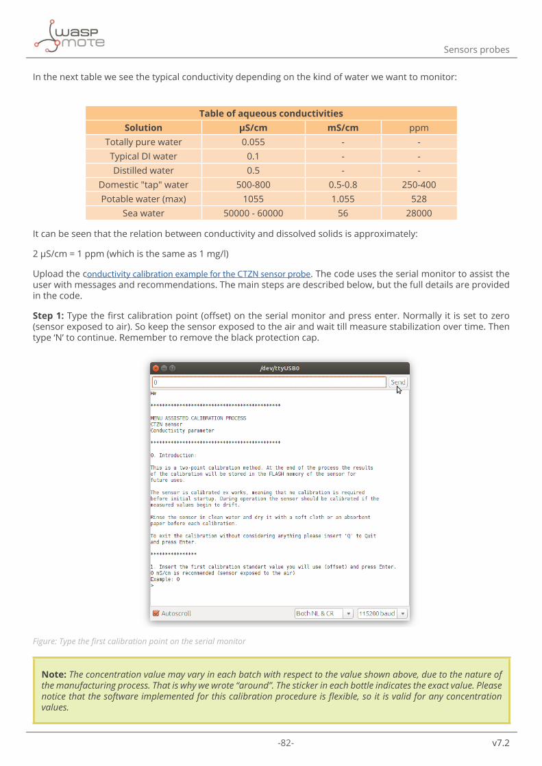
-82- v7.2
Sensors probes
In the next table we see the typical conductivity depending on the kind of water we want to monitor:
Table of aqueous conductivitiesSolution µS/cm mS/cm ppm
Totally pure water 0.055 - -Typical DI water 0.1 - -Distilled water 0.5 - -
Domestic "tap" water 500-800 0.5-0.8 250-400Potable water (max) 1055 1.055 528
Sea water 50000 - 60000 56 28000
It can be seen that the relation between conductivity and dissolved solids is approximately:
2 µS/cm = 1 ppm (which is the same as 1 mg/l)
Upload the conductivity calibration example for the CTZN sensor probe. The code uses the serial monitor to assist the user with messages and recommendations. The main steps are described below, but the full details are provided in the code.
Step 1: Type the first calibration point (offset) on the serial monitor and press enter. Normally it is set to zero (sensor exposed to air). So keep the sensor exposed to the air and wait till measure stabilization over time. Then type ‘N’ to continue. Remember to remove the black protection cap.
Figure: Type the first calibration point on the serial monitor
Note: The concentration value may vary in each batch with respect to the value shown above, due to the nature of the manufacturing process. That is why we wrote “around”. The sticker in each bottle indicates the exact value. Please notice that the software implemented for this calibration procedure is flexible, so it is valid for any concentration values.

-83- v7.2
Sensors probes
Step 2: Type the second calibration point (slope) on the serial monitor and press enter.
Figure: Type the second calibration point on the serial monitor
Step 3: Pour enough buffer solution in a clean baker to cover the sensor head. Immerse the sensor inside the chosen conductivity standard buffer solution. Wait until values are stabilized over time and type ‘N’ to continue.
Figure: Immersing the sensor inside the calibration buffer solution

-84- v7.2
Sensors probes
Step 4: Save calibration data into the sensor by typing operators name and date of calibration. Then, the sensor values will be printed on the screen to check if the measures are done correctly.
Figure: Save the calibration data
Step 5: Remove the sensor from the buffer solution and clean it carefully as described below.

-85- v7.2
Sensors probes
4.6.4.2. Cleaning the sensor
The CTZN sensor probe is designed to avoid periodic cleaning due to its immunity to fouling effects.
However, depending the environment it is recommendable to check the sensor to avoid solids to get tangled up into the sensor coil.
Figure: Cleaning the sensor
Finally, if the sensor is not going to be used during a large period, it is important to clean the sensor prior to storing it. Use tap water, soap to rinse the sensor carefully and a soft towel to dry it and remove the biologic material.

-86- v7.2
Sensors probes
4.6.5. Installation
It is important to think about a few aspects before installing the sensor on the field:
• The sensor body should be easily accessible for cleaning, regular maintenance and calibration. • The sensor body must be firmly fastened to avoid sensor swing and possible collisions with the surrounding
objects that can damage the sensor. • If the sensor is installed totally immersed., it should be fastened from the body and not from the cable. The
cable is not designed to hold the sensor and it could be damaged. • Avoid bubbles around the sensor. • For those users interested in measuring directly inside pipes, there are pipe segments with a protected
measurement point. As an optional accessory for this sensor, Libelium offers a pipe mounting adapter (available in PVC and in stainless steel) which can be connected to those special pipe segments.
Figure: Typical installation on a pipe

-87- v7.2
Sensors probes
Figure: Another Typical installation on a lake
A complete sensor manual can be found on the manufacturer’s website.
4.6.6. Application examples
• Urban wastewater treatment • Industrial effluent treatment • Surface water monitoring • Sea water • Fish farming
4.6.7. Calibration report
Together with this sensor we provide a factory calibration report in which the manufacturer ensures that the sensor has passed a calibration procedure with traceability.

-88- v7.2
Sensors probes
4.7. Turbidity and temperature NTU sensor probeThe Turbidity and temperature NTU sensor probe is based in infrared light reflections which allows measuring turbidity in a great range of applications. Besides, the sensor measures suspended solids and also an internal temperature sensor is included for temperature compensation of the turbidity measures.
Some sensors in the market calculate the suspended solids from the turbidity value. By contrast, the NTU sensor probe takes its own measure. However, to measure suspended solids correctly, the NTU sensor probe is directly calibrated on the material to be measured and an external laboratory is needed to analyze the sample. This service is not provided by Libelium.
The NTU sensor probe measures according to DIN EN ISO 7027, required in many Smart Water quality applications.
Note: The optical windows of the NTU sensor probe is vulnerable to chemicals (organic solvents, acids and strong bases, peroxide and hydrocarbons). Avoid using the sensor if they are present in your application.
Figure: Turbidity and temperature NTU sensor probe

-89- v7.2
Sensors probes
4.7.1. Specifications
Turbidity sensor:
• Technology: Optical infrared (IR 880 nm) • Ranges NTU: 0 to 4000 NTU in 5 ranges:
- 0 - 50 NTU - 0 - 200 NTU - 0 - 1000 NTU - 0 - 4000 NTU - AUTOMATIC
• Ranges mg/L: 0 to 4500 mg/L - Range 0 - 500 mg/L according to NF EN 872 - Range >500 mg/L according to NF T 90 105 2
• Resolution: 0.01 to 1 NTU - mg/L • Accuracy: < 5% of the reading • Response time: <5 s
Temperature sensor:
• Technology: NTC • Range: 0 °C to +50 °C • Resolution: 0.01 °C • Accuracy: ±0.5 °C
Common:
• Default cable length: 15 m • Maximum pressure: 5 bars • Body material: DELRIN • IP classification: IP68 • Storage temperature: 0 °C to +60 °C
Figure: Sensor parts: (1) temperature sensor, (2) optical window, (3) sensor body

-90- v7.2
Sensors probes
Figure: Dimensions of the NTU sensor probe
4.7.2. Measurement process
The sensor probe provides a digital signal using the SDI-12 protocol.
Reading code:
{ // 1. Declare an object for the sensor Aqualabo_NTU mySensor(XTR_SOCKET_A); // 2. Turn ON the sensor mySensor.ON(); // 3. Read the sensor. Values stored in class variables // Check complete code example for details mySensor.read(); // 4. Turn off the sensor mySensor.OFF();}
During the sensor measurement, there is a small stabilization time of a few seconds, so it is recommendable to wait until the values remains stable over time.
A complete example code for reading this sensor probe can be found in the following link:
http://www.libelium.com/development/waspmote/examples/sw-xtr-19-ntu-sensor-reading

-91- v7.2
Sensors probes
4.7.3. Socket
Connect the NTU sensor probe to Plug & Sense! Smart Water Xtreme in any of the sockets shown in the image below.
Figure: Available sockets for the NTU sensor probe
4.7.4. Maintenance
4.7.4.1. Calibration
By default, the sensor is factory-calibrated, therefore calibration may not be needed for the first usage. Nevertheless, prior to carry out the sensor calibration, please bear in mind the next comments:
• It is important that the sensor and the buffer solutions have the same temperature, so before starting the calibration process leave all the necessary elements in the same temperature conditions. Besides, wait for sensor temperature stabilization once it has been immersed.
• During the sensor measurement, there is a small stabilization time of a few seconds, so please wait until the values remains stable over time.
• The calibration must be done every month to get a reasonable accuracy in the measurements. However, depending the application, the time between two calibrations would vary. It is highly recommended to do a test as close as possible to the conditions of the final application to check the sensor drift over time. This will allow to adjust the calibration periods according to the required accuracy.
• The buffer solution bottles must be closed properly after the usage, to prevent deviations on the default values.
First of all, ensure that all necessary elements are present. It is important that if a calibration process is started, it should be completed to save the results in the sensor internal memory. Do not abandon the calibration process and always follow the given steps and guidelines to avoid a sensor misconfiguration. If the process needs to be repeated or abandoned, always type the ‘Q’ command to exit the calibration procedure.
Libelium provides the necessary standard buffer solution to calibrate the Smart Water Xtreme sensor probes. Refer to the calibration solution section for more information.

-92- v7.2
Sensors probes
Figure: Necessary elements for NTU sensor probe calibration
The sensor calibration can be done only on socket E. Owing to that, connect the sensor probe to socket E of the Plug & Sense! Smart Water Xtreme unit to calibrate the sensor, as shown in the image below. Do not use any other Plug & Sense! socket to calibrate a sensor. It will not work.
Figure: Connecting the sensor to the calibration socket
The NTU sensor probe allows to calibrate temperature and turbidity. Please read below the necessary steps to calibrate each parameter.
Temperature calibration
The temperature calibration process is the same for all Plug & Sense! Smart Water Xtreme sensor probes. Refer to the previously described temperature calibration section of the OPTOD sensor probe for details.
NTU calibration
By default the NTU sensor is in automatic range, which means that the internal circuitry is able to select the best sensor range according to the measure which is taking place. If turbidity values are between two ranges, some variations may be observed as a result of the automatic mode where the sensor is trying to adjust itself.

-93- v7.2
Sensors probes
The turbidity calibration requires a formazine solution with a concentration matching the middle of the
selected range. The solution could be prepared from a 4000 NTU standard solution mixing the necessary parts with distilled water.
The solutions of concentrations lower than 1000 NTU deteriorate fast, so do not preserve a solution during several days. By contrast, solutions around 2000 NTU could be preserved in the refrigerator for 2 or 3 weeks in a opaque and properly closed flask. Remember to shake the solutions before using them.
One instance could be selecting the range of 0 to 1000 NTU. it would be needed a concentration of 500 NTU as a second calibration point (half range). As an example, a reasonable amount of liquid to calibrate would be 200 ml, therefore to obtain 200 ml with a concentration of 500 NTU it would be needed 25 ml of 4000 NTU solution and 175 ml of distilled water (up to 200 ml).
Step 1: Select the range of the sensor to calibrate.
Step 2: Type the first calibration point (offset) on the serial monitor and press enter.
Figure: Type the first calibration point on the serial monitor
Step 3: The first calibration point (offset) is intended to be zero. So immerse the sensor in distilled water. The sensor needs to be at least 5 cm far from the baker walls to avoid side effects that could distort the measure. Remove the black protection cap before immersing the sensor in the buffer solution. Wait until values are stabilized over time and type ‘N’ to continue.

-94- v7.2
Sensors probes
Note: Do not discard the black protection cap and keep it for the future. It will be useful if the sensor needs to be stored for a large period.
Figure: Immersing the sensor inside the calibration buffer solution
Step 4: Remove the sensor from the buffer solution and clean it carefully as previously described.
Step 5: Type the second calibration point (slope) on the serial monitor and press enter.
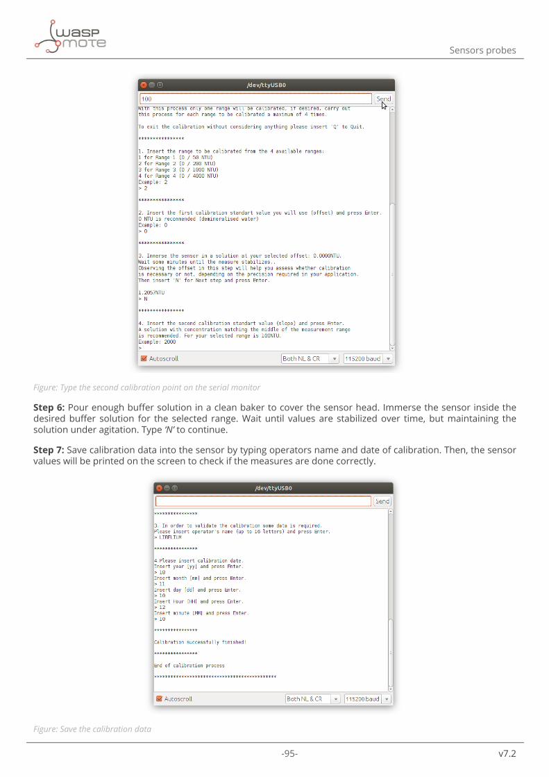
-95- v7.2
Sensors probes
Figure: Type the second calibration point on the serial monitor
Step 6: Pour enough buffer solution in a clean baker to cover the sensor head. Immerse the sensor inside the desired buffer solution for the selected range. Wait until values are stabilized over time, but maintaining the solution under agitation. Type ‘N’ to continue.
Step 7: Save calibration data into the sensor by typing operators name and date of calibration. Then, the sensor values will be printed on the screen to check if the measures are done correctly.
Figure: Save the calibration data

-96- v7.2
Sensors probes
4.7.4.2. Cleaning the sensor
The NTU sensor probe needs to be cleaned periodically to remove the possible fouling or other biologic material that could appear in the sensor. Organic deposits present on the sensor lens, such as a biofilm or silt, may cause measurement errors. These deposits should be removed carefully with warm soapy water and a soft sponge. Never use abrasive agents (e.g. scouring sponge). In addition, calcium deposits could be removed by immersing the sensor in a diluted hydrochloric acid solution (maximum concentration of 5%) for several minutes.
Figure: Cleaning the sensor
Finally, if the sensor is not going to be used during a large period, it is important to clean the sensor prior to storing it. Remember to place the protection cap together with a moisture absorbent element (like a piece of cotton).
4.7.5. Installation
It is important to think about a few aspects before installing the sensor on the field:
• The sensor body should be easily accessible for cleaning, regular maintenance and calibration. • The sensor body must be firmly fastened to avoid sensor swing and possible collisions with the surrounding
objects that can damage the sensor. • If the sensor is installed totally immersed, it should be fastened from the body and not from the cable. The
cable is not designed to hold the sensor and it could be damaged. • Avoid bubbles around the sensor. • For those users interested in measuring directly inside pipes, there are pipe segments with a protected
measurement point. As an optional accessory for this sensor, Libelium offers a pipe mounting adapter (available in PVC and in stainless steel) which can be connected to those special pipe segments.

-97- v7.2
Sensors probes
Figure: Typical installation on a pipe
Figure: Another Typical installation on a lake
Moreover, due to the optical sensor technology, the NTU sensor probe is affected by external light sources that could distort the measures. Try to place the sensor where it light does not reach the sensor probe’s head.

-98- v7.2
Sensors probes
Figure: Turbidity sensor probe wrongly and correctly placed
If the sensor is used in a hard environment where animals, solids or other environmental elements can damage the sensor, a protection strainer is available as an accessory of extra protection. Contact our Sales department through the next link if you require more information: http://www.libelium.com/contact.
Figure: Protection strainer accessory
A complete sensor manual can be found on the manufacturer’s website.
4.7.6. Application examples
• Drinking water management • Fish farming • Industrial and public sewage treatment plants • Process engineering plants
4.7.7. Calibration report
Together with this sensor we provide a factory calibration report in which the manufacturer ensures that the sensor has passed a calibration procedure with traceability.
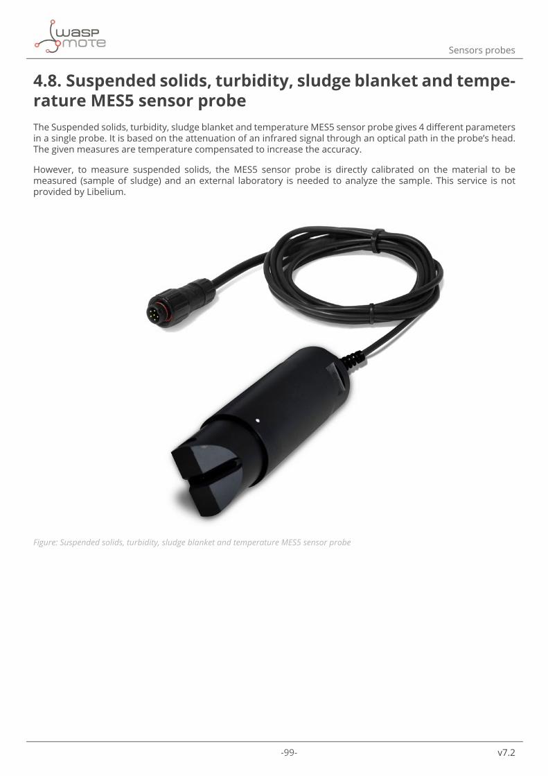
-99- v7.2
Sensors probes
4.8. Suspended solids, turbidity, sludge blanket and tempe-rature MES5 sensor probeThe Suspended solids, turbidity, sludge blanket and temperature MES5 sensor probe gives 4 different parameters in a single probe. It is based on the attenuation of an infrared signal through an optical path in the probe’s head. The given measures are temperature compensated to increase the accuracy.
However, to measure suspended solids, the MES5 sensor probe is directly calibrated on the material to be measured (sample of sludge) and an external laboratory is needed to analyze the sample. This service is not provided by Libelium.
Figure: Suspended solids, turbidity, sludge blanket and temperature MES5 sensor probe

-100- v7.2
Sensors probes
4.8.1. Specifications
Turbidity sensor:
• Technology: Optical infrared (IR 870 nm) • Ranges:
- SS : 0 - 50 g/L - Turbidity : 0 - 4000 FAU - Sludge blanket : 0 - 100%
• Resolution: - SS : 0.01 g/L - Turbidity : 0.01 to 1 FAU - Sludge blanket : 0.01 to 0.1%
• Accuracy: - SS< 10% - Turbidity : ±5% (range 200 - 4000 FAU) - Sludge blanket : ±2%
• Response time: < 35 seconds
Temperature sensor:
• Technology: NTC • Range: -5 °C to +50 °C • Resolution: 0.01 °C • Accuracy: ±0.5 °C
Common:
• Default cable length: 15 m • IP classification: IP68 • Maximum pressure: 5 bars • Body material: DELRIN • Storage temperature: 0 °C to +60 °C

-101- v7.2
Sensors probes
Figure: Sensor parts: (1) optical window, (2) temperature sensor, (3) sensor body
Figure: Dimensions of the MES5 sensor probe
4.8.2. Measurement process
The MES5 sensor provides a digital signal using the SDI-12 protocol.
Reading code:
{ // 1. Declare an object for the sensor Aqualabo_MES5 mySensor(XTR_SOCKET_A); // 2. Turn ON the sensor mySensor.ON(); // 3. Read the sensor. Values stored in class variables // Check complete code example for details mySensor.read(); // 4. Turn off the sensor mySensor.OFF();}

-102- v7.2
Sensors probes
During the sensor measurement, there is a small stabilization time of a few seconds, so it is recommendable to wait until the values remains stable over time.
A complete example code for reading this sensor probe can be found in the following link:
http://www.libelium.com/development/waspmote/examples/sw-xtr-27-mes5-sensor-reading
4.8.3. Socket
Connect the MES5 sensor probe to Plug & Sense! Smart Water Xtreme in any of the sockets shown in the image below.
Figure: Available sockets for the MES5 sensor probe
4.8.4. Maintenance
4.8.4.1. Calibration
By default, the sensor is factory-calibrated, therefore calibration may not be needed for the first usage. Nevertheless, prior to carry out the sensor calibration, please bear in mind the next comments:
• It is important that the sensor and the buffer solutions have the same temperature, so before starting the calibration process leave all the necessary elements in the same temperature conditions. Besides, wait for sensor temperature stabilization once it has been immersed.
• During the sensor measurement, there is a small stabilization time of a few seconds, so please wait until the values remains stable over time.
• The calibration must be done every month to get a reasonable accuracy in the measurements. However, depending the application, the time between two calibrations would vary. It is highly recommended to do a test as close as possible to the conditions of the final application to check the sensor drift over time. This will allow to adjust the calibration periods according to the required accuracy.
• The buffer solution bottles must be closed properly after the usage, to prevent deviations on the default values.
• The sensor needs to be rinsed with clean water before each calibration. First of all, ensure that all necessary elements are present. It is important that if a calibration process is started, it should be completed to save the results in the sensor internal memory. Do not abandon the calibration process and always follow the given steps and guidelines to avoid a sensor misconfiguration. If the process needs to be repeated or abandoned, always type the ‘Q’ command to exit the calibration procedure.

-103- v7.2
Sensors probes
Libelium provides the necessary standard buffer solution to calibrate the Smart Water Xtreme sensor probes. Refer to the calibration solution section for more information.
Figure: Necessary elements for MES5 sensor probe calibration
The sensor calibration can be done only on socket E. Owing to that, connect the sensor probe to socket E of the Plug & Sense! Smart Water Xtreme unit to calibrate the sensor, as shown in the image below. Do not use any other Plug & Sense! socket to calibrate a sensor. It will not work.
Figure: Connecting the sensor to the calibration socket
The MES5 sensor probe does not allow to calibrate suspended solids by itself and an external laboratory is needed to analyze the sample of the sludge blanket. This service is not provided by Libelium.
However, it allows to calibrate temperature and turbidity. Please read below the necessary steps to calibrate each parameter.
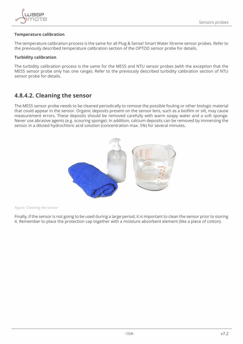
-104- v7.2
Sensors probes
Temperature calibration
The temperature calibration process is the same for all Plug & Sense! Smart Water Xtreme sensor probes. Refer to the previously described temperature calibration section of the OPTOD sensor probe for details.
Turbidity calibration
The turbidity calibration process is the same for the MES5 and NTU sensor probes (with the exception that the MES5 sensor probe only has one range). Refer to the previously described turbidity calibration section of NTU sensor probe for details.
4.8.4.2. Cleaning the sensor
The MES5 sensor probe needs to be cleaned periodically to remove the possible fouling or other biologic material that could appear in the sensor. Organic deposits present on the sensor lens, such as a biofilm or silt, may cause measurement errors. These deposits should be removed carefully with warm soapy water and a soft sponge. Never use abrasive agents (e.g. scouring sponge). In addition, calcium deposits can be removed by immersing the sensor in a diluted hydrochloric acid solution (concentration max. 5%) for several minutes.
Figure: Cleaning the sensor
Finally, if the sensor is not going to be used during a large period, it is important to clean the sensor prior to storing it. Remember to place the protection cap together with a moisture absorbent element (like a piece of cotton).

-105- v7.2
Sensors probes
4.8.5. Installation
It is important to think about a few aspects before installing the sensor on the field:
• The sensor body should be easily accessible for cleaning, regular maintenance and calibration. • The sensor body must be firmly fastened to avoid sensor swing and possible collisions with the surrounding
objects that can damage the sensor. • If the sensor is installed totally immersed, it should be fastened from the body and not from the cable. The
cable is not designed to hold the sensor and it could be damaged. • Avoid bubbles around the sensor. • For those users interested in measuring directly inside pipes, there are pipe segments with a protected
measurement point. As an optional accessory for this sensor, Libelium offers a pipe mounting adapter (available in PVC and in stainless steel) which can be connected to those special pipe segments.
Figure: Typical installation on a pipe

-106- v7.2
Sensors probes
Figure: Another Typical installation on a lake
A complete sensor manual can be found on the manufacturer’s website.
4.8.6. Application examples
• Urban Waste water treatment (Inlet/sewage water (SS, Turbidity), Aeration basin (SS), Outlet (Turbidity) • Treatment of industrial effluents (Aeration basin (SS)), Clarifier (Sludge blanket), Outlet (Turbidity) • Sludge treatment (Centrifugation) • Dredging site (turbidity)
4.8.7. Calibration report
Together with this sensor we provide a factory calibration report in which the manufacturer ensures that the sensor has passed a calibration procedure with traceability.
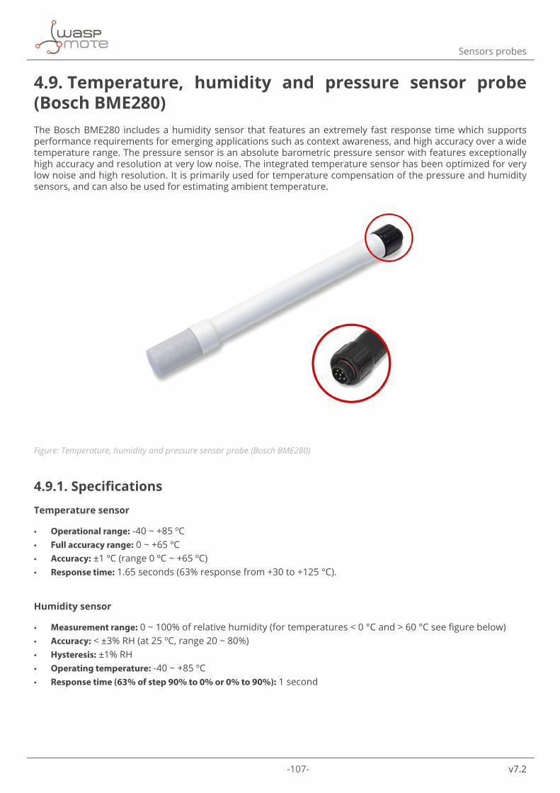
-107- v7.2
Sensors probes
4.9. Temperature, humidity and pressure sensor probe (Bosch BME280)The Bosch BME280 includes a humidity sensor that features an extremely fast response time which supports performance requirements for emerging applications such as context awareness, and high accuracy over a wide temperature range. The pressure sensor is an absolute barometric pressure sensor with features exceptionally high accuracy and resolution at very low noise. The integrated temperature sensor has been optimized for very low noise and high resolution. It is primarily used for temperature compensation of the pressure and humidity sensors, and can also be used for estimating ambient temperature.
Figure: Temperature, humidity and pressure sensor probe (Bosch BME280)
4.9.1. Specifications
Temperature sensor
• Operational range: -40 ~ +85 ºC • Full accuracy range: 0 ~ +65 ºC • Accuracy: ±1 ºC (range 0 ºC ~ +65 ºC) • Response time: 1.65 seconds (63% response from +30 to +125 °C).
Humidity sensor
• Measurement range: 0 ~ 100% of relative humidity (for temperatures < 0 °C and > 60 °C see figure below) • Accuracy: < ±3% RH (at 25 ºC, range 20 ~ 80%) • Hysteresis: ±1% RH • Operating temperature: -40 ~ +85 ºC • Response time (63% of step 90% to 0% or 0% to 90%): 1 second

-108- v7.2
Sensors probes
Figure: Humidity sensor operating range
Pressure sensor
• Measurement range: 30 ~ 110 kPa • Operational temperature range: -40 ~ +85 ºC • Full accuracy temperature range: 0 ~ +65 ºC • Absolute accuracy: ±0.1 kPa (0 ~ 65 ºC)
4.9.2. Measurement process
The Temperature, humidity and pressure sensor provides a digital signal using the I2C protocol.
Reading code:
{ // 1. Declare an object for the sensor bme mySensor(XTR_SOCKET_A); // 2. Turn ON the sensor mySensor.ON(); // 3. Read the sensor. Store parameters in local variables floattemperature=mySensor.getTemperature(); floathumidity=mySensor.getHumidity(); floatpressure=mySensor.getPressure(); // 4. Turn off the sensor mySensor.OFF();}
You can find a complete example code for reading this sensor probe in the following link:
http://www.libelium.com/development/waspmote/examples/sw-xtr-32-bme280-sensor-reading
-109- v7.2
Sensors probes
4.9.3. Socket
Connect the Temperature, humidity and pressure sensor probe (Bosch BME280) to Plug & Sense! Smart Water Xtreme in the sockets A or D.
4.9.4. Application examples
• Weather observation and forecast • Evapotranspiration analysis • Control heating, ventilation or air conditioning in greenhouses • Warning regarding dryness or high temperatures • Pressure compensation for dissolved oxygen accurate calculations

-110- v7.2
Sensors probes
4.10. Luminosity sensor probe (AMS TSL2561)This is a light-to-digital converter that transforms light intensity into a digital signal output. This device combines one broadband photo-diode (visible plus infrared) and one infrared-responding photo-diode on a single CMOS integrated circuit capable of providing a near-photopic response over an effective 20-bit dynamic range (16-bit resolution). Two integrating ADCs convert the photo-diode currents to a digital output that represents the irradiance measured on each channel. This digital output in lux is derived using an empirical formula to approximate the human eye response.
Figure: Luminosity sensor probe (AMS TSL2561)
4.10.1. Specifications
• Operating temperature: -30 ºC to +80 ºC • Dynamic range: 0.1 to 40000 Lux • Spectral range: 300 – 1100 nm • Usage: indoors and outdoors
Figure: Luminosity sensor graphic

-111- v7.2
Sensors probes
4.10.2. Measurement process
The luminosity sensor provides a digital signal using the I2C protocol.
Reading code:
{ // 1. Declare an object for the sensor luxes mySensor(XTR_SOCKET_A); // 2. Turn ON the sensor mySensor.ON(); // 3. Read the sensor. Store parameters in local variables uint32_tluminosity=mySensor.getLuminosity(); // 4. Turn off the sensor mySensor.OFF();}
You can find a complete example code for reading this sensor probe in the following link:
http://www.libelium.com/development/waspmote/examples/sw-xtr-33-tsl2561-sensor-reading
4.10.3. Socket
Connect the Luminosity sensor probe to Plug & Sense! Smart Water Xtreme in the sockets A or D.
Figure: Available sockets for the Luminosity sensor probe
4.10.4. Application examples
• Light presence detection

-112- v7.2
Sensors probes
4.11. Ultrasound sensor probe (MaxBotix MB7040)The Ultrasound sensor probe (MaxBotix MB7040) has high acoustic power output along with real-time auto calibration for changing conditions (voltage and acoustic or electrical noise) that ensure users receive the most reliable ranging data for every reading taken in air.
Figure: Ultrasound sensor (MaxBotix MB7040)
4.11.1. Specifications
• Operation frequency: 42 kHz • Maximum detection distance: 765 cm • Usage: indoors and outdoors (IP-67)
A 1.72” dia. 43.8 mm dia.
B 2.00” 50.7 mm
C 0.58” 14.4 mm
D 0.31” 7.9 mm
E 0.18” 4.6 mm
F 0.1” 2.54 mm
G 3/4” National Pipe Thread Straight
H 1.032” dia. 26.2 dia.
I 1.37” 34.8 mm
weight: 1.76 oz. ; 50 gramsFigure: Ultrasound sensor dimensions

-113- v7.2
Sensors probes
4.11.2. Measurement process
The ultrasound sensor provides a digital signal using the I2C protocol.
Reading code:
{ // 1. Declare an object for the sensor ultrasound mySensor(XTR_SOCKET_A); // 2. Turn ON the sensor mySensor.ON(); // 3. Read the sensor. Store parameters in local variables uint16_tdistance=mySensor.getDistance(); // 4. Turn off the sensor mySensor.OFF();}
You can find a complete example code for reading this sensor probe in the following link:
http://www.libelium.com/development/waspmote/examples/sw-xtr-34-mb7040-sensor-reading
4.11.3. Socket
Connect the Ultrasound sensor probe to Plug & Sense! Smart Water Xtreme in the sockets A or D.

-114- v7.2
Sensors probes
4.11.4. Installation
The ultrasound sensor probe may be placed in different positions. The sensor can be focused directly to the point we want to measure.
Figure: Ultrasound sensor (MaxBotix MB7040) installation
4.11.5. Application examples
• Tank level measurement • River height control • Early flood detection • Sea tide monitoring • Proximity zone detection • People detection • Distance measuring • Security systems • Motion detection • Collision avoidance

-115- v7.2
Sensors probes
4.12. Eureka Manta multi sensor probeThe Eureka Manta sensor probe is designed to unify a large number of sensors in only one probe. Owing to that, the Eureka Manta multi probe is highly configurable, offering a great number of parameter combinations to meet the requirements even for the most demanding applications.
Parameters like chlorophyll, Blue-Green Algae (BGA, also known as cyanobacteria), ammonium, nitrates, chloride, sodium or calcium can be measured with this multi probe, achieving up to 13 different measures.
Note: Ion Selective Electrode probes are not recommended for seawater applications due to their special calibration requirements and their reliability in terms of stability and accuracy. Same happens with any ISE sensor in the market. Contact your sales agent for more information.
Figure: Eureka Manta multi sensor probe
4.12.1. Common specifications
Fluorometers:
• Chlorophyll a – blue: 0 to 500 g/l • Chlorophyll a – red: > 500 g/l • CDOM/DOM: 0 to 1250 or 0 to 5000 ppb • Resolution: 6 digits with maximum of two decimals • Accuracy: linearity of 0.99 R²
Ion selective electrodes (ISE):
• Ammonium: 0 to 100 mg/l as nitrogen • Nitrate: 0 to 100 mg/l as nitrogen • Chloride: 0 to 18000 mg/l • Sodium: 0 to 20000 mg/l • Calcium: 0 to 40000 mg/l • Resolution: 0.1 • Accuracy: 5% or 2 mg/l • Ammonium and nitrate require tip replacement every 3 - 6 months
Common:

-116- v7.2
Sensors probes
• Diameter: 3.5’’ or 4’’ • Length: 19’’ • Temperature Range: -5 °C to +50 °C • Depth rating: 200 m, maximum for ISE and TDG sensor is 15 meters • IP classification: IP68 (complete and continuous immersion in water, up to 200 meters depth)
Figure: Probes assembled on the Eureka Manta multi probe
4.12.2. Fluorometer Chlorophyll
Fluorometric sensors emit light at a certain wavelength and look for a very specific wavelength in return. The magnitude of the return light is relatable to the amount of the analyzed parameter. They require non-trivial calibration.
In the case of chlorophyll, two fluorometers are available with the ranges shown below:
- Chlorophyll a – blue: 0 to 500 g/l - Chlorophyll a – red: > 500 g/l
4.12.3. Fluorometer Phycocyanin (freshwater BGA)
Phycocyanin fluorometer works in the same way as chlorophyll fluorometer. The main applications are lakes, rivers, ground water, oceanographic, process waters, waste waters or laboratory research. The range of this fluorometer is 0 to 40,000 ppb.
4.12.4. Fluorometer Phycoerythrin (marine BGA)

-117- v7.2
Sensors probes
There is a specific version of the fluorometer BGA for sea water applications with a range of 0 to 750 ppb.

-118- v7.2
Sensors probes
4.12.5. Fluorometer CDOM / FDOM
The CDOM (Colored Dissolved Organic Matter) and the FDOM (Fluorescent Dissolved Organic Matter) fluorometers work in the same way as previous fluorometers.
The ranges for these fluorometers are:
- CDOM: 0 to 1250 ppb - FDOM: 0 to 5000 ppb
4.12.6. Ion selective electrode – Ammonium
This sensor has a membrane that is selective for ammonium. The electrode’s filling solution contains a salt sensitive to ammonium, and the difference between that salt’s concentration and the ammonium concentration in the measured water produces a charge separation. That charge separation is measured, relative to the reference electrode, as a voltage that changes predictably with changes in the ammonium concentration in the water adjacent the membrane.
The range of this sensor is 0 to 100 mg/l as nitrogen.
4.12.7. Ion selective electrode – Nitrate
This sensor has a membrane that is selective for nitrate and works in the same way as Ammonium electrode.
The range of this sensor is 0 to 100 mg/l as nitrogen.
4.12.8. Ion selective electrode – Chloride
This sensor has a membrane that is selective for chloride and works in the same way as Ammonium electrode.
The range of this sensor is 0 to 18000 mg/l.
4.12.9. Ion selective electrode – Sodium
This sensor has a membrane that is selective for sodium and works in the same way as Ammonium electrode.
The range of this sensor is 0 to 20000 mg/l.
4.12.10. Ion selective electrode – Calcium
This sensor has a membrane that is selective for calcium and works in the same way as Ammonium electrode.
The range of this sensor is 0 to 40000 mg/l.

-119- v7.2
Sensors probes
4.12.11. Measurement process
The Eureka sensor provides a digital signal using the RS-232 protocol.
Reading code:
{ // 1. Declare an object for the sensor eureka mySensor(XTR_SOCKET_F); // 2. Turn ON the sensor mySensor.ON(); // 3. Read the sensor. Values stored in class variables // Check complete code example for details mySensor.read(); // 4. Turn off the sensor mySensor.OFF();}
During the sensor measurement, there is a small stabilization time of a few seconds, so it is recommendable to wait until the values remains stable over time.
A complete example code for reading this sensor probe can be found in the development section of Libelium website.

-120- v7.2
Sensors probes
4.12.12. Socket
Connect the Eureka sensor probe to Plug & Sense! Smart Water Xtreme in any of the sockets shown in the image below.
Figure: Available sockets for the Eureka sensor probe
4.12.13. Maintenance
4.12.13.1. Calibration
By default, the sensor is factory-calibrated, therefore calibration may not be needed for the first usage. Nevertheless, prior to carry out the sensor calibration, please bear in mind the next comments:
• It is important that the sensor and the buffer solutions have the same temperature, so before starting the calibration process leave all the necessary elements in the same temperature conditions. Besides, wait for sensor temperature stabilization once it has been immersed.
• During the sensor measurement, there is a small stabilization time of a few seconds, so please wait until the values remains stable over time.
• The calibration must be done every month to get a reasonable accuracy in the measurements. However, depending the application, the time between two calibrations would vary. It is highly recommended to do a test as close as possible to the conditions of the final application to check the sensor drift over time. This will allow to adjust the calibration periods according to the required accuracy.
• The buffer solution bottles must be closed properly after the usage, to prevent deviations on the default values.
• The sensor needs to be rinsed with clean water before each calibration.

-121- v7.2
Sensors probes
4.12.13.2. Cleaning the sensor
The Eureka Manta sensor probe needs to be cleaned periodically to remove the possible fouling or other biologic material that could appear in the sensor. Organic deposits present on the sensor lens, such as a biofilm or silt, may cause measurement errors. These deposits should be removed carefully with warm soapy water and a soft sponge. Never use abrasive agents (e.g. scouring sponge). Despite the sensor has its own wiper for probe cleaning, cleaning maintenance tasks can not be omitted.
Figure: Typical fouling on the Eureka Manta sensor probes
Finally, if the sensor is not going to be used during a large period, it is important to clean the sensor prior to storing it. Remember to place the protection cap together with a moisture absorbent element (like a piece of cotton).

-122- v7.2
Sensors probes
4.12.14. Installation
It is important to think about a few aspects before installing the sensor on the field:
• The sensor body should be easily accessible for cleaning, regular maintenance and calibration. • The sensor body must be firmly fastened to avoid sensor swing and possible collisions with the surrounding
objects that can damage the sensor. • If the sensor is installed totally immersed, it should be fastened from the body and not from the cable. The
cable is not designed to hold the sensor and it could be damaged. • Avoid bubbles around the sensor.
A complete sensor manual can be found on the manufacturer’s website.
4.12.15. Application examples
• Buoy deployments • Telemetered deployments • Unattended logging • Process monitoring

-123- v7.2
Sensors probes
4.13. Calibration solutionsLibelium provides several calibration solutions to calibrate the sensors.
pH Calibration kit
Characteristics: • 4.0 pH (red), 7.0 pH (yellow), 10.0 pH (blue) ±0.02 pH at 25 ºC • 125 ml each
This kit includes three buffer solutions of 4.0 pH, 7.0 pH and 10.0 pH, of colors red, yellow and blue respectively.
The calibration process is described in section “Calibration procedure”, when handling them pay attention to the information provided in the MSDS.
Figure: Image of the pH calibration kit
Conductivity calibration kits
Characteristics:
• 3 kits for K = 0.1, K = 1 and K = 10 • around 0.084 mS, 1.413 mS, 12.88 mS, 80 mS and 150 mS at 25 ºC • 125 ml each
Six solutions for sensor calibration are included within these 3 kits, so the probe can be calibrated in a wide range of conductivities
Figure: Image of the 3 conductivity calibration kits. Concentration values may vary.

-124- v7.2
Sensors probes
ORP Calibration solution
Characteristics:
• 225 mV ±2 mV at 25 ºC • 100 ml each
The ORP calibration solution provides a 225mV output at 25ºC (beware that it may change at different temperatures) which facilitates the adjustment of the sensor output to the actual values of oxidation-reduction potential. Note that this buffer will keep its properties for 30 days once open. It is recommended to store refrigerated.
Figure: Image of the ORP calibration solution
Dissolved Oxygen calibration solution
Characteristics:
• 0mg/ml at 25ºC • 100ml
In the case of the dissolved oxygen sensor Libelium provides a solution of 0mg/ml adequate to test the sensor. Though it provides a very good approximation for the zero output, it is not recommended for calibration.
Figure: Image of the dissolved oxygen calibration solution

-125- v7.2
Sensors probes
Note: remember to read carefully the material safety data sheets you can findin the “Safety guides” section of this guide, in order to take the corresponding precautions when manipulating these solutions and dispose them in the appropriate way.
Turbidity calibration kits
Characteristics:
2 kits for low and medium/high turbidities:
• 4000 NTU • 125 ml
The formazine solution of 4000 NTU allows the user to obtain any concentration lower than 4000 NTU by mixing with distilled water, in order to calibrate in the desired range.
Figure: Turbidity calibration solution
Note: remember to read carefully the material safety data sheets you can find in the “Safety guides” section of this guide, in order to take the corresponding precautions when manipulating these solutions and dispose them in the appropriate way.

-126- v7.2
Board configuration and programming
5. Board configuration and programming5.1. 5.1 Hardware configurationThe Plug & Sense! Smart Water Xtreme model does not require special handling of the hardware by the user, except for placing the sensors in their corresponding socket. In the previous sections each sensor connection has been described.
It is important to remark that Smart Water Xtreme model is only available in the Waspmote Plug & Sense! Line. It is not available for Waspmote OEM line.
5.2. API
5.2.1. Before starting to program
When using the Plug & Sense! Smart Water Xtreme model, remember that it is mandatory to include the WaspSensorXtr library by introducing the next line at the beginning:
#include <WaspSensorXtr.h>
The library manages the power supply and communication lines between Waspmote and the sockets. Prior to read the sensor probes, the user must declare an object of the corresponding sensor class, specifying the socket where the sensor is placed. The next table enumerates each sensor class.
Sensor probe Sensor classOptical dissolved oxygen and temperature OPTOD Aqualabo_OPTOD
pH, ORP and temperature PHEHT Aqualabo_PHEHT
Conductivity, salinity and temperature C4E Aqualabo_C4E
Turbidity and temperature NTU Aqualabo_NTU
Inductive conductivity, salinity and temperature CTZN Aqualabo_CTZN
Suspended solids, turbidity, sludge blanket and temperature MES5
Aqualabo_MES5
Each sensor class manages the Smart Water Xtreme sensor board according to its needs, so there is no need to turn on or off the whole board, as is often needed with other Libelium sensor boards. After declaring the object, the sensor can be turned on or off independently from each other. Incidentally, do not forget turning off the sensors to save battery when they are no longer needed.
The next snippet shows how to declare an object for the sensor PHEHT and then how to turn on, read and turn off the sensor:
{ // 1. Declare an object for the sensor Aqualabo_PHEHT mySensor(XTR_SOCKET_C); // 2. Turn ON the sensor mySensor.ON(); // 3. Read the sensor. Values stored in class variables // Check complete code example for details mySensor.read(); // 4. Turn off the sensor mySensor.OFF();}
-127- v7.2
Board configuration and programming
The read() function stores the sensor values in a public object. It does not return the values directly. The user can refer to the dedicated sensor example to see how the sensor values can be accessed. In the case of the PHEHT sensor, values will be printed by USB with the following snippet.
{ // 4. Print information USB.println(F(“PHEHT”)); USB.print(F(“Temperature: “)); USB.printFloat(mySensor.sensorPHEHT.temperature, 2); USB.println(F(“degreesCelsius”)); USB.print(F(“pH: “)); USB.printFloat(mySensor.sensorPHEHT.pH, 2); USB.println(); USB.print(F(“pH: “)); USB.printFloat(mySensor.sensorPHEHT.pHMV, 2); USB.println(F(“ mV”)); USB.print(F(“Redox: “)); USB.printFloat(mySensor.sensorPHEHT.redox, 2); USB.println(F(“ mV”)); }
The Temperature, humidity and pressure, the Ultrasound and the Luminosity sensors have their own reading functions in contrast to the rest of the Smart Water Xtreme sensors. This is due to these sensors can be used in other Plug & Sense! models and they share the same functions into the Waspmote API. Refer to the dedicated sensor example for further details.
5.2.2. Sending sensor values with the Frame class
Owing to the large amount of parameters that can be read by the Plug & Sense! Smart Water Xtreme model, a special frame type must be used with the Frame class in order to send the values correctly.
{ // It is mandatory to specify the Smart Water Xtreme type frame.setFrameType(INFORMATION_FRAME_WTR_XTR);}
A complete example code for using the frame class can be found in the following link:
http://www.libelium.com/development/waspmote/examples/sw-xtr-04-frame-class-utility
Refer to the Data Frame Guide for more information:
http://www.libelium.com/downloads/documentation/data_frame_guide.pdf

-128- v7.2
Consumption
6. Consumption6.1. Consumption tableThe following table shows the power consumption of the Plug & Sense! Smart Water Xtreme sensor probes. Remember that the sensor board can be completely disconnected by turning off all sensors, reducing the consumption to zero.
Added to that, some sensors are quite complex and they have various working modes, so the power consumption could vary. The values shown in the table are averages when the sensor is being read by Waspmote.
Sensor probe Consumption
Standby Average Pulse
Optical dissolved oxygen and temperature OPTOD 25 µA 7.3 mA 100 mA
pH, ORP and temperature PHEHT 25 µA 6.8 mA 500 mA
Conductivity, salinity and temperature C4E 25 µA 9.2 mA 500 mA
Turbidity and temperature NTU 40 µA 4.2 mA 500 mA
Inductive conductivity, salinity and temperature CTZN
50 µA 15.5 mA 700 mA
Suspended solids, turbidity, sludge blanket and temperature MES5
25 µA 4.5 mA 100 mA
Figure: Table: Power consumption for each sensor probe

-129- v7.2
Safety guides
7. Safety guides7.1. Turbidity calibration solution, 4000 NTUSection 1: Product and company identification
Product name: Solution of formazine 4000 NTU
Product use: Equipment maintenance
Article number: 1SF007, 1SF008, 1SF009
Relevant identified uses of the substance or mixture and uses advised against: No further relevant information available.
Application of the substance / the mixture: Reagent for analysis.
Details of the supplier of the safety data sheet
Manufacturer/Supplier:
Orchidis laboratoire, 90 rue du Pr Milliez 94506. Champigny/Marne, France
+33 1 55 09 10 10 mel: [email protected]
Further information obtainable from: - - -
Emergency telephone number:
Urgences n°unique d’appel européen: 112 (UE)
Urgences: centre anti poison +33(0)1 40 05 48 48
Liste des centres anti poison: ORFILA +33(0)1 45 42 59 59
#US/Canada/International:
24 Hour Emergency Information Telephone Numbers
CHEMTREC (USA): 800.424.9300
CANUTEC (Canada): 613.424.6666
International 703-527-3887
#Spain:
Centro Nacional de Toxicología
Teléfono: 91 5620420
http://www.mju.es/toxicologia

-130- v7.2
Safety guides
Section 2: Composition/ information on ingredients
COMPONENT CAS NO. % Other
Methenamine 100-97-0 2.5 – 5%
EINECS: 202-905-8
Flam. Liq. 1, H224; Flam. Sol. 2, H228;
Skin Sens. 1, H317
hydrazinium(2+) sulphate 10034-93-2 0.1 – 1%
EINECS: 233-110-4
Acute Tox. 3, H311; Acute Tox. 2, H330;
Carc. 1A, H350;
Acute Tox. 4, H302;
Skin Sens. 1, H317
Section 3: Hazards identification
Classification of the substance or mixture: Classification according to Regulation (EC) No 1272/2008
GHS08 health hazard
Carc. 1A - H350 May cause cancer.
GHS07
Skin Sens. 1 H317 May cause an allergic skin reaction.
Label elements
Labeling according to Regulation (EC) No 1272/2008
The product is classified and labeled according to the CLP regulation.
Hazard pictograms
GHS07 GHS08
Signal word Danger
Hazard-determining components of labelling:
methenamine
hydrazinium(2+) sulphate
Hazard statements
H317 May cause an allergic skin reaction.
H350 May cause cancer.
Precautionary statements
P261 - Avoid breathing dust/fume/gas/mist/vapours/spray.
P280 - Wear protective gloves/protective clothing/eye protection/face protection.

-131- v7.2
Safety guides
P321 - Specific treatment (see on this label).
P308+P313 - IF exposed or concerned: Get medical advice/attention.
P405 - Store locked up.
P501 - Dispose of contents/container in accordance with local/regional/national/international regulations.
Additional information: Restricted to professional users.
Other hazards
Results of PBT and vPvB assessment
PBT: Not applicable.
vPvB: Not applicable.
Section 4: First aid measures
Description of first aid measures
General information: Immediately remove any clothing soiled by the product.
After inhalation:
Supply fresh air and to be sure call for a doctor.
In case of unconsciousness place patient stably in side position for transportation.
After skin contact: Immediately wash with water and soap and rinse thoroughly.
After eye contact: Rinse opened eye for several minutes under running water.
After swallowing: If symptoms persist consult doctor.
Most important symptoms and effects, both acute and delayed No further relevant information available.
Indication of any immediate medical attention and special treatment needed
No further relevant information available.
Section 5: Fire fighting measures
Extinguishing media
Suitable extinguishing agents:
CO2, powder or water spray. Fight larger fires with water spray or alcohol resistant foam.
Special hazards arising from the substance or mixture No further relevant information available.
Advice for firefighters
Protective equipment: No special measures required.

-132- v7.2
Safety guides
Section 6: Accidental release measures
Personal precautions, protective equipment and emergency procedures Not required.
Environmental precautions: Do not allow to enter sewers/ surface or ground water.
Methods and material for containment and cleaning up:
Absorb with liquid-binding material (sand, diatomite, acid binders, universal binders, sawdust).
Dispose contaminated material as waste according to item 13.
Ensure adequate ventilation.
Reference to other sections
See Section 7 for information on safe handling.
See Section 8 for information on personal protection equipment.
Section 7: Handling and storage
Precautions for safe handling
Ensure good ventilation/exhaustion at the workplace.
Open and handle receptacle with care.
Prevent formation of aerosols.
Information about fire - and explosion protection: Keep respiratory protective device available.
Conditions for safe storage, including any incompatibilities
Storage:
Requirements to be met by storerooms and receptacles: No special requirements.
Information about storage in one common storage facility: Not required.
Further information about storage conditions: Keep container tightly sealed.
Specific end use(s) No further relevant information available.
Section 8: Exposure controls/ personal protection
Additional information about design of technical facilities: No further data; see item 7.
Control parameters
Ingredients with limit values that require monitoring at the workplace:
The product does not contain any relevant quantities of materials with critical values that have to be monitored at the workplace.
Additional information: The lists valid during the making were used as basis.
Exposure controls
Personal protective equipment:

-133- v7.2
Safety guides
General protective and hygienic measures:
Keep away from foodstuffs, beverages and feed.
Immediately remove all soiled and contaminated clothing
Wash hands before breaks and at the end of work.
Store protective clothing separately.
Respiratory protection:
In case of brief exposure or low pollution use respiratory filter device. In case of intensive or longer exposure use self-contained respiratory protective device.
Protection of hands:
Protective gloves
The glove material has to be impermeable and resistant to the product/ the substance/ the preparation.
Due to missing tests no recommendation to the glove material can be given for the product/ the preparation/ the chemical mixture.
Selection of the glove material on consideration of the penetration times, rates of diffusion and the degradation
Material of gloves
The selection of the suitable gloves does not only depend on the material, but also on further marks of quality and varies from manufacturer to manufacturer. As the product is a preparation of several substances, the resistance of the glove material can not be calculated in advance and has therefore to be checked prior to the application.
Penetration time of glove material
The exact break through time has to be found out by the manufacturer of the protective gloves and has to be observed.
Eye protection:
Tightly sealed goggles
Section 9: Physical and chemical properties
Information on basic physical and chemical properties
General Information
Appearance:
Form: Fluid
Colour:Whitish
Odour: Odourless
Odour threshold: Not determined.
pH-value at 20 °C: 6
Change in condition
Melting point/Melting range: Undetermined

-134- v7.2
Safety guides
Boiling point/Boiling range: 100 °C
Flash point: Not applicable.
Flammability (solid, gaseous): Not applicable.
Ignition temperature:
Decomposition temperature: Not determined.
Self-igniting: Product is not selfigniting.
Danger of explosion: Product does not present an explosion hazard.
Explosion limits:
Lower: Not determined.
Upper: Not determined.
Vapour pressure: Not determined.
Density at 20 °C: 1 g/cm3
Relative density: Not determined.
Vapour density: Not determined.
Evaporation rate: Not determined.
Solubility in / Miscibility with water: Not miscible or difficult to mix.
Partition coefficient (n-octanol/water): Not determined.
Viscosity: Not determined.
Dynamic: Not determined.
Kinematic: Not determined.
Solvent content:
Organic solvents: 0.0 %
Water: 94.5 %
Solids content: 5.0 %
Other information: No further relevant information available.
Section 10: Stability and reactivity
Reactivity No further relevant information available.
Chemical stability
Thermal decomposition / conditions to be avoided: No decomposition if used according to specifications.
Possibility of hazardous reactions No dangerous reactions known.
Conditions to avoid No further relevant information available.
Incompatible materials: No further relevant information available.

-135- v7.2
Safety guides
Hazardous decomposition products: No dangerous decomposition products known.
Section 11: Toxicological information
Information on toxicological effects
Acute toxicity Based on available data, the classification criteria are not met.
LD/LC50 values relevant for classification:
10034-93-2 hydrazinium(2+) sulphate
Oral LD50 601 mg/kg (rat)
Primary irritant effect:
Skin corrosion/irritation Based on available data, the classification criteria are not met.
Serious eye damage/irritation Based on available data, the classification criteria are not met.
Respiratory or skin sensitisation
May cause an allergic skin reaction.
CMR effects (carcinogenity, mutagenicity and toxicity for reproduction)
Germ cell mutagenicity Based on available data, the classification criteria are not met.
Carcinogenicity
May cause cancer.
Reproductive toxicity Based on available data, the classification criteria are not met.
STOT-single exposure Based on available data, the classification criteria are not met.
STOT-repeated exposure Based on available data, the classification criteria are not met.
Aspiration hazard Based on available data, the classification criteria are not met.
Section 12: Ecological information
Toxicity
Aquatic toxicity: No further relevant information available.
Persistence and degradability No further relevant information available.
Bioaccumulative potential No further relevant information available.
Mobility in soil No further relevant information available.
Additional ecological information:
General notes:
Water hazard class 3 (German Regulation) (Self-assessment): extremely hazardous for water
Do not allow product to reach ground water, water course or sewage system, even in small quantities.
Danger to drinking water if even extremely small quantities leak into the ground.

-136- v7.2
Safety guides
Results of PBT and vPvB assessment
PBT: Not applicable.
vPvB: Not applicable.
Other adverse effects No further relevant information available.
Section 13: Disposal considerations
Waste treatment methods
Recommendation Must not be disposed together with household garbage. Do not allow product to reach sewage system.
Uncleaned packaging:
Recommendation: Disposal must be made according to official regulations.
Section 14: Transport information
UN-Number
ADR, ADN, IMDG, IATA - Void
UN proper shipping name
ADR, ADN, IMDG, IATA - Void
Transport hazard class(es)
ADR, ADN, IMDG, IATA
Class - void
Packing group
ADR, IMDG, IATA - Void
Environmental hazards:
Marine pollutant: No
Special precautions for user - Not applicable.
Transport in bulk according to Annex II of Marpol and the IBC Code - Not applicable.
UN “Model Regulation”: Void
Additional Information:
This product may be shipped as part of a chemical kit composed of various compatible dangerous goods for
analytical or testing purposes. This kit would have the following classification : proper shipping name: chemical kit, hazard class 9, UN number 3316, package group II, EMS code : F-A, S-P

-137- v7.2
Safety guides
Section 15: Regulatory information
Safety, health and environmental regulations/legislation specific for the substance or mixture
Labeling according to Regulation (EC) No 1272/2008
The product is classified and labeled according to the CLP regulation.
Hazard pictograms
GHS07
GHS08
Signal word Danger
Hazard-determining components of labeling:
methenamine
hydrazinium(2+) sulphate
Hazard statements
H317 May cause an allergic skin reaction.
H350 May cause cancer.
Precautionary statements
P261 Avoid breathing dust/fume/gas/mist/vapours/spray.
P280 Wear protective gloves/protective clothing/eye protection/face protection.
P321 Specific treatment (see on this label).
P308+P313 IF exposed or concerned: Get medical advice/attention.
P405 Store locked up.
P501 Dispose of contents/container in accordance with local/regional/national/international regulations.
Directive 2012/18/EU
Named dangerous substances - ANNEX I None of the ingredients is listed.
REGULATION (EC) No 1907/2006 ANNEX XVII Conditions of restriction: 3
National regulations:
Additional classification according to Decree on Hazardous Materials, Annex II:
Carcinogenic hazardous material group III (dangerous).
Information about limitation of use:
Workers are not allowed to be exposed to the hazardous carcinogenic materials contained in this preparation.
Exceptions can be made by the authorities in certain cases.
Chemical safety assessment: A Chemical Safety Assessment has not been carried out.

-138- v7.2
Safety guides
Section 16: Other information
This information is based on our present knowledge. However, this shall not constitute a guarantee for any specific product features and shall not establish a legally valid contractual relationship.
Relevant phrases:
H224 Extremely flammable liquid and vapour.
H228 Flammable solid.
H302 Harmful if swallowed.
H311 Toxic in contact with skin.
H317 May cause an allergic skin reaction.
H330 Fatal if inhaled.
H350 May cause cancer.
Abbreviations and acronyms:
ADR: Accord européen sur le transport des marchandises dangereuses par Route (European Agreement concerning the International Carriage of Dangerous Goods by Road)
IMDG: International Maritime Code for Dangerous Goods
IATA: International Air Transport Association
GHS: Globally Harmonised System of Classification and Labelling of Chemicals
EINECS: European Inventory of Existing Commercial Chemical Substances
ELINCS: European List of Notified Chemical Substances
CAS: Chemical Abstracts Service (division of the American Chemical Society)
LC50: Lethal concentration, 50 percent
LD50: Lethal dose, 50 percent
PBT: Persistent, Bioaccumulative and Toxic
vPvB: very Persistent and very Bioaccumulative
Flam. Liq. 1: Flammable liquids – Category 1
Flam. Sol. 2: Flammable solids – Category 2
Acute Tox. 4: Acute toxicity – Category 4
Acute Tox. 3: Acute toxicity – Category 3
Acute Tox. 2: Acute toxicity – Category 2
Skin Sens. 1: Skin sensitisation – Category 1
Carc. 1A: Carcinogenicity – Category 1A
Carc. 1A: Carcinogenicity – Category 1A

-139- v7.2
Safety guides
7.2. KCl storage solutionSection 1: Identification of the substance/mixture and of the company/undertaking
1.1 Product identifier
Trade name: Solution de Conservation
Article number: 1SC009, 1SC021, 1SC035
1.2 Relevant identified uses of the substance or mixture and uses advised against
No further relevant information available.
Application of the substance / the mixture Reagent for analysis.
1.3 Details of the supplier of the safety data sheet
Manufacturer/Supplier:
Aqualabo
90 rue du Professeur P.Milliez - 94506 Champigny-sur-Marne - France
+33 1 55 09 10 10
mail: [email protected]
www.aqualabo.fr (all of our SDS can be downloaded from our website, section “Services”).
Further information obtainable from: - - -
1.4 Emergency telephone number:
Urgences n°unique d’appel européen : 112 (UE)
Urgences : Centre anti poison +33(0)1 40 05 48 48
Liste des centres anti poison : ORFILA +33(0)1 45 42 59 59
#US/Canada/International:
24 Hour Emergency Information Telephone Numbers
CHEMTREC (USA): 800.424.9300
CANUTEC (Canada): 613.424.6666
International 703-527-3887
#Spain:
Centro Nacional de Toxicología
Teléfono: 91 5620420
http://www.mju.es/toxicologia

-140- v7.2
Safety guides
Section 2: Hazards identification
2.1 Classification of the substance or mixture
Classification according to Regulation (EC) No 1272/2008
The product is not classified, according to the CLP regulation.
2.2 Label elements
Labelling according to Regulation (EC) No 1272/2008 Void
Hazard pictograms Void
Signal word Void
Hazard statements Void
Additional information:
Safety data sheet available on request.
2.3 Other hazards
Results of PBT and vPvB assessment
PBT: Not applicable.
vPvB: Not applicable.
Section 3: Composition/information on ingredients
Chemical characterisation: Mixtures
Description: Mixture of substances listed below with nonhazardous additions.
Dangerous components:CAS: 56-81-5
EINECS: 200-289-5
glycerol substance with a Community workplace exposure limit
25-50%
CAS: 10043-35-3
EINECS: 233-139-2
boric acid Repr. 1B, H360FD 0.1-1%
SVHC10043-35-3 boric acid
Additional information: For the wording of the listed hazard phrases refer to section 16.

-141- v7.2
Safety guides
Section 4: First aid measures
4.1 Description of first aid measures
General information: No special measures required.
After inhalation: Supply fresh air; consult doctor in case of complaints.
After skin contact: Generally the product does not irritate the skin.
After eye contact: Rinse opened eye for several minutes under running water.
After swallowing: If symptoms persist consult doctor.
4.2 Most important symptoms and effects, both acute and delayed No further relevant information available.
4.3 Indication of any immediate medical attention and special treatment needed
No further relevant information available.
Section 5: Firefighting measures
5.1 Extinguishing media
Suitable extinguishing agents: Use fire extinguishing methods suitable to surrounding conditions.
5.2 Special hazards arising from the substance or mixture No further relevant information available.
5.3 Advice for firefighters
Protective equipment: No special measures required.
Section 6: Accidental release measures
6.1 Personal precautions, protective equipment and emergency procedures Not required.
6.2 Environmental precautions: Do not allow to enter sewers/ surface or ground water.
6.3 Methods and material for containment and cleaning up:
Absorb with liquid-binding material (sand, diatomite, acid binders, universal binders, sawdust).
6.4 Reference to other sections
No dangerous substances are released.
See Section 7 for information on safe handling.
See Section 8 for information on personal protection equipment.
See Section 13 for disposal information.

-142- v7.2
Safety guides
Section 7: Handling and storage
7.1 Precautions for safe handling No special measures required.
Information about fire - and explosion protection: No special measures required.
7.2 Conditions for safe storage, including any incompatibilities
Storage:
Requirements to be met by storerooms and receptacles: No special requirements.
Information about storage in one common storage facility: Not required.
Further information about storage conditions: None.
7.3 Specific end use(s) No further relevant information available.
Section 8: Exposure controls/personal protection
Additional information about design of technical facilities: No further data; see item 7.
8.1 Control parameters
Ingredients with limit values that require monitoring at the workplace:
56-81-5 glycerol
WEL: Long-term value: 10 mg/m³
Additional information: The lists valid during the making were used as basis.
8.2 Exposure controls
Personal protective equipment:
General protective and hygienic measures:
The usual precautionary measures are to be adhered to when handling chemicals.
Respiratory protection: Not required.
Protection of hands:
The glove material has to be impermeable and resistant to the product/ the substance/ the preparation.
Due to missing tests no recommendation to the glove material can be given for the product/ the preparation/ the chemical mixture.
Selection of the glove material on consideration of the penetration times, rates of diffusion and the degradation
Material of gloves
The selection of the suitable gloves does not only depend on the material, but also on further marks of quality and varies from manufacturer to manufacturer. As the product is a preparation of several substances, the resistance of the glove material can not be calculated in advance and has therefore to be checked prior to the application.
Penetration time of glove material
The exact break through time has to be found out by the manufacturer of the protective gloves and has to be observed.

-143- v7.2
Safety guides
Eye protection: Goggles recommended during refilling
Section 9: Physical and chemical properties
9.1 Information on basic physical and chemical properties
General Information
Appearance:
Form: Fluid
Colour: Pink
Odour: Odourless
Odour threshold: Not determined.
pH-value at 20 °C: 1
Change in condition
Melting point/freezing point: Undetermined.
Initial boiling point and boiling range: 100 °C
Flash point: 160 °C
Flammability (solid, gas): Not applicable.
Ignition temperature: 400 °C
Decomposition temperature: Not determined.
Auto-ignition temperature: Product is not selfigniting.
Explosive properties: Product does not present an explosion hazard.
Explosion limits:
Lower: 0.9 Vol %
Upper: Not determined.
Vapour pressure: Not determined.
Density at 20 °C: 1.174 g/cm³
Relative density Not determined.
Vapour density Not determined.
Evaporation rate Not determined.
Solubility in / Miscibility with water: Not miscible or difficult to mix.
Partition coefficient: n-octanol/water: Not determined.
Viscosity:
Dynamic: Not determined.
Kinematic: Not determined.

-144- v7.2
Safety guides
Solvent content:
Organic solvents: 26.9 %
Water: 51.0 %
Solids content: 0.0 %
9.2 Other information No further relevant information available.
Section 10: Stability and reactivity
10.1 Reactivity No further relevant information available.
10.2 Chemical stability
Thermal decomposition / conditions to be avoided: No decomposition if used according to specifications.
10.3 Possibility of hazardous reactions No dangerous reactions known.
10.4 Conditions to avoid No further relevant information available.
10.5 Incompatible materials: No further relevant information available.
10.6 Hazardous decomposition products: No dangerous decomposition products known.
Section 11: Toxicological information
11.1 Information on toxicological effects
Acute toxicity Based on available data, the classification criteria are not met.
LD/LC50 values relevant for classification:
56-81-5 glycerol
Oral LD50 12,600 mg/kg (rat)
7447-40-7 potassium chloride
Oral LD50 2,600 mg/kg (rat)
7778-77-0 potassium dihydrogenorthophosphate
Oral LD50 4,640 mg/kg (rat)
10043-35-3 boric acid
Oral LD50 2,660 mg/kg (rat)
Primary irritant effect:
Skin corrosion/irritation Based on available data, the classification criteria are not met.
Serious eye damage/irritation Based on available data, the classification criteria are not met.
Respiratory or skin sensitisation Based on available data, the classification criteria are not met.
CMR effects (carcinogenity, mutagenicity and toxicity for reproduction)
Germ cell mutagenicity Based on available data, the classification criteria are not met.

-145- v7.2
Safety guides
Carcinogenicity Based on available data, the classification criteria are not met.
Reproductive toxicity Based on available data, the classification criteria are not met.
STOT-single exposure Based on available data, the classification criteria are not met.
STOT-repeated exposure Based on available data, the classification criteria are not met.
Aspiration hazard Based on available data, the classification criteria are not met.
Section 12: Ecological information
12.1 Toxicity
Aquatic toxicity: No further relevant information available.
12.2 Persistence and degradability No further relevant information available.
12.3 Bioaccumulative potential No further relevant information available.
12.4 Mobility in soil No further relevant information available.
Additional ecological information:
General notes:
Water hazard class 1 (German Regulation) (Self-assessment): slightly hazardous for water
Do not allow undiluted product or large quantities of it to reach ground water, water course or sewage system.
Rinse off of bigger amounts into drains or the aquatic environment may lead to decreased pH-values. A low pH-value harms aquatic organisms. In the dilution of the use-level the pH-value is considerably increased, so that after the use of the product the aqueous waste, emptied into drains, is only low water-dangerous.
12.5 Results of PBT and vPvB assessment
PBT: Not applicable.
vPvB: Not applicable.
12.6 Other adverse effects No further relevant information available.
Section 13: Disposal considerations
13.1 Waste treatment methods
Recommendation Smaller quantities can be disposed of with household waste.
Uncleaned packaging:
Recommendation: Disposal must be made according to official regulations.

-146- v7.2
Safety guides
Section 14: Transport information
14.1 UN-Number
ADR, ADN, IMDG, IATA Void
14.2 UN proper shipping name
ADR, ADN, IMDG, IATA Void
14.3 Transport hazard class(es)
ADR, ADN, IMDG, IATA
Class Void
14.4 Packing group
ADR, IMDG, IATA Void
14.5 Environmental hazards:
Marine pollutant: No
14.6 Special precautions for user Not applicable.
14.7 Transport in bulk according to Annex II of Marpol and the IBC Code Not applicable.
UN “Model Regulation”: Void
Additional Informations This product may be shipped as part of a chemical kit composed of various compatible dangerous goods for analytical or testing purposes. This kit would have the following classification : proper shipping name : chemical kit, hazard class 9, UN number 3316, package group II, EMS
code : F-A, S-P
Section 15: Regulatory information
15.1 Safety, health and environmental regulations/legislation specific for the substance or mixture
Labelling according to Regulation (EC) No 1272/2008 Void
Hazard pictograms Void
Signal word Void
Hazard statements Void
Directive 2012/18/EU
Named dangerous substances - ANNEX I None of the ingredients is listed.
National regulations:
Other regulations, limitations and prohibitive regulations
Substances of very high concern (SVHC) according to REACH, Article 57
10043-35-3 boric acid
15.2 Chemical safety assessment: A Chemical Safety Assessment has not been carried out.

-147- v7.2
Safety guides
Section 16: Other information
This information is based on our present knowledge. However, this shall not constitute a guarantee for any specific product features and shall not establish a legally valid contractual relationship.
Relevant phrases
H360FD May damage fertility. May damage the unborn child.
Abbreviations and acronyms:
ADR: Accord européen sur le transport des marchandises dangereuses par Route (European Agreement concerning the International Carriage of Dangerous Goods by Road)
IMDG: International Maritime Code for Dangerous Goods
IATA: International Air Transport Association
GHS: Globally Harmonised System of Classification and Labelling of Chemicals
EINECS: European Inventory of Existing Commercial Chemical Substances
ELINCS: European List of Notified Chemical Substances
CAS: Chemical Abstracts Service (division of the American Chemical Society)
LC50: Lethal concentration, 50 percent
LD50: Lethal dose, 50 percent
PBT: Persistent, Bioaccumulative and Toxic
SVHC: Substances of Very High Concern
vPvB: very Persistent and very Bioaccumulative
Repr. 1B: Reproductive toxicity – Category 1B

-148- v7.2
Safety guides
7.3. pH 4.00 Calibration SolutionSection 1: Product and Company Identification • Product name: pH 4.00 Calibration Solution • Synonyms/General Names: pH 4.00 Buffer solution • Product Use: For device calibration
#US/Canada/International: 24 Hour Emergency Information Telephone NumbersCHEMTREC (USA): 800.424.9300CANUTEC (Canada): 613.424.6666International 703-527-3887
#Spain: Centro Nacional de ToxicologíaTeléfono: 91 5620420http://institutodetoxicologia.justicia.es/
Section 2: Hazards IdentificationRed liquid; no odor.CAUTION! Body tissue irritant.Target organs: None known.This material is not considered hazardous by the OSHA Hazard Communication Standard (29 CFR 1910.1200) if used properly.
Section 3: Composition / Information on Ingredients • Potassium Hydrogen Phthalate: 10.21g, 1-2% • Hydrochloric Acid: 1ml, <1% • Water: (7732-18-5), 97-99% • Food coloring: <1%
Section 4: First Aid MeasuresAlways seek professional medical attention after first aid measures are provided.
• Eyes: Immediately flush eyes with excess water for 15 minutes, lifting lower and upper eyelids occasionally. • Skin: Immediately flush skin with excess water for 15 minutes while removing contaminated clothing. • Ingestion: Call Poison Control immediately. Rinse mouth with cold water. Give victim 1-2 cups of water or milk
to drink. Induce vomiting immediately. • Inhalation: Remove to fresh air. If not breathing, give artificial respiration.
Section 5: Fire Fighting MeasuresNon-combustible solution. When heated to decomposition, emits acrid fumes.
Protective equipment and precautions for firefighters: Use foam or dry chemical to extinguish fire.
Firefighters should wear full fire fighting turn-out gear and respiratory protection (SCBA). Cool container with water spray. Material is not sensitive to mechanical impact or static discharge.
-149- v7.2
Safety guides
Section 6: Accidental Release MeasuresUse personal protection recommended in Section 8. Isolate the hazard area and deny entry to unnecessary and unprotected personnel. Contain spill with sand or absorbent material and place in sealed bag or container for disposal. Ventilate and wash spill area after pickup is complete. See Section 13 for disposal information.
Section 7: Handling and Storage • Handling: Use with adequate ventilation and do not breathe dust or vapor. Avoid contact with skins, eyes, or
clothing. Wash hands thoroughly after handling. • Storage: Store in General Storage Area with other items with no specific storage hazards. Store in a cool, dry,
well-ventilated, locked store room away from incompatible materials.
Section 8: Exposure Controls / Personal ProtectionUse ventilation to keep airborne concentrations below exposure limits. Have approved eyewash facility, safety shower, and fire extinguishers readily available. Wear chemical splash goggles and chemical resistant clothing such as gloves and aprons. Wash hands thoroughly after handling material and before eating or drinking.
Exposure guidelines: Sodium Hydroxide: OSHA PEL: 2 mg/m3, ACGIH: TLV: N/A, STEL: 2 mg/m3 ceiling.
Section 9: Physical and Chemical Properties
Molecular formula: N/A Appearance: Red liquid
Molecular weight: N/A Odor: No odor
Specific Gravity: 1.00 g/mL @ 20°C Odor Threshold: N/A
Vapor Density (air=1): 0.7 (water) Solubility: Complete
Melting Point Freezes: @ ~0 °C Evaporation rate: N/A (Butyl acetate = 1)
Boiling Point/Range: ~100°C Partition Coefficient: N/A (log POW)
Vapor Pressure (20°C): N/A pH: 4.0
Flash Point: N/A LEL: N/A
Autoignition Temp: N/A UEL: N/A
Section 10: Stability and Reactivity • Avoid heat and moisture. • Stability: Stable under normal conditions of use and storage. • Incompatibility: Acids, alkalis. • Shelf life: Indefinite if stored properly.
Section 11: Toxicology Information • Acute Symptoms/Signs of exposure: Eyes: Redness, tearing, itching, burning, conjunctivitis. Skin: Redness,
itching. • Ingestion: Irritation and burning sensations of mouth and throat, nausea, vomiting and abdominal pain. • Inhalation: Irritation of mucous membranes, coughing, wheezing, shortness of breath. • Chronic Effects: No information found. • Sensitization: none expected.
Sodium Hydroxide: LD50 [oral, rabbit]; N/A; LC50 [rat]; N/A; LD50 Dermal [rabbit]; N/A.
Material has not been found to be a carcinogen nor produce genetic, reproductive, or developmental effects.

-150- v7.2
Safety guides
Section 12: Ecological Information • Ecotoxicity (aquatic and terrestrial): Not considered an environmental hazard.
Section 13: Disposal ConsiderationsCheck with all applicable local, regional, and national laws and regulations. Local regulations may be more stringent than regional or national regulations. Small amounts of this material may be suitable for sanitary sewer or trash disposal.
Section 14: Transport Information • DOT Shipping Name: Not regulated by DOT • DOT Hazard Class: • Identification Number: • Canada TDG: Not regulated by TDG • Hazard Class: • UN Number:
Section 15: Regulatory Information • EINECS: Not listed • TSCA: All components are listed or are exempt • WHMIS Canada: Not WHMIS Controlled • California Proposition 65: Not listed
The product has been classified in accordance with the hazard criteria of the Controlled Products Regulations and the MSDS contains all the information required by the Controlled Products Regulations.
Section 16: Other Information • Current Issue Date: January 2011
Disclaimer: Libelium believes that the information herein is factual but is not intended to be all inclusive. The information relates only to the specific material designated and does not relate to its use in combination with other materials or its use as to any particular process. Because safety standards and regulations are subject to change and because Libelium has no continuing control over the material, those handling, storing or using the material should satisfy themselves that they have current information regarding the particular way the material is handled, stored or used and that the same is done in accordance with federal, state and local law. Libelium makes no warranty, expressed or implied, including (without limitation) warranties with respect to the completeness or continuing accuracy of the information contained herein or with respect to fitness for any particular use.

-151- v7.2
Safety guides
7.4. pH 7.00 Calibration Solution Section 1: Product and Company Identification • Product name: pH 7.00 Calibration Solution • Synonyms/General Names: pH 7.00 Buffer solution • Product Use: For device calibration
#US/Canada/International: 24 Hour Emergency Information Telephone NumbersCHEMTREC (USA): 800.424.9300CANUTEC (Canada): 613.424.6666International 703-527-3887
#Spain: Centro Nacional de ToxicologíaTeléfono: 91 5620420http://institutodetoxicologia.justicia.es/
Section 2: Hazards IdentificationYellow liquid; no odor.CAUTION! Body tissue irritant.Target organs: None known.This material is not considered hazardous by the OSHA Hazard Communication Standard (29 CFR 1910.1200) if used properly.
Section 3: Composition / Information on Ingredients • Potassium Dihydrogen Phosphate: 6.81g, <1% • Sodium Hydroxide: 291mL, <1% • Water: (7732-18-5), >99% • Food coloring: <1%
Section 4: First Aid MeasuresAlways seek professional medical attention after first aid measures are provided.
• Eyes: Immediately flush eyes with excess water for 15 minutes, lifting lower and upper eyelids occasionally. • Skin: Immediately flush skin with excess water for 15 minutes while removing contaminated clothing. • Ingestion: Call Poison Control immediately. Rinse mouth with cold water. Give victim 1-2 cups of water or milk
to drink. Induce vomiting immediately. • Inhalation: Remove to fresh air. If not breathing, give artificial respiration.
Section 5: Fire Fighting MeasuresNoncombustible solution. When heated to decomposition, emits acrid fumes.
Protective equipment and precautions for firefighters: Use foam or dry chemical to extinguish fire.
Firefighters should wear full fire fighting turn-out gear and respiratory protection (SCBA). Cool container with water spray. Material is not sensitive to mechanical impact or static discharge.

-152- v7.2
Safety guides
Section 6: Accidental Release MeasuresUse personal protection recommended in Section 8. Isolate the hazard area and deny entry to unnecessary and unprotected personnel. Contain spill with sand or absorbent material and place in sealed bag or container for disposal. Ventilate and wash spill area after pickup is complete. See Section 13 for disposal information.
Section 7: Handling and Storage • Handling: Use with adequate ventilation and do not breathe dust or vapor. Avoid contact with skins, eyes, or
clothing. Wash hands thoroughly after handling. • Storage: Store in General Storage Area with other items with no specific storage hazards. Store in a cool, dry,
well-ventilated, locked store room away from incompatible materials.
Section 8: Exposure Controls / Personal ProtectionUse ventilation to keep airborne concentrations below exposure limits. Have approved eyewash facility, safety shower, and fire extinguishers readily available. Wear chemical splash goggles and chemical resistant clothing such as gloves and aprons. Wash hands thoroughly after handling material and before eating or drinking.
Exposure guidelines: Sodium Hydroxide: OSHA PEL: 2 mg/m3, ACGIH: TLV: N/A, STEL: 2 mg/m3 ceiling.
Section 9: Physical and Chemical Properties
Molecular formula: N/A Appearance: Yellow liquid
Molecular weight: N/A Odor: No odor
Specific Gravity: 1.00 g/mL @ 20°C Odor Threshold: N/A
Vapor Density (air=1): 0.7 (water) Solubility: Complete
Melting Point Freezes: @ ~0 °C Evaporation rate: N/A (Butyl acetate = 1)
Boiling Point/Range: ~100°C Partition Coefficient: N/A (log POW)
Vapor Pressure (20°C): N/A pH: 7.0
Flash Point: N/A LEL: N/A
Autoignition Temp: N/A UEL: N/A
Section 10: Stability and Reactivity • Avoid heat and moisture. • Stability: Stable under normal conditions of use and storage. • Incompatibility: Acids, alkalis. • Shelf life: Indefinite if stored properly.
Section 11: Toxicology Information • Acute Symptoms/Signs of exposure: Eyes: Redness, tearing, itching, burning, conjunctivitis. Skin: Redness,
itching. • Ingestion: Irritation and burning sensations of mouth and throat, nausea, vomiting and abdominal pain. • Inhalation: Irritation of mucous membranes, coughing, wheezing, shortness of breath. • Chronic Effects: No information found. • Sensitization: none expected.
Sodium Hydroxide: LD50 [oral, rabbit]; N/A; LC50 [rat]; N/A; LD50 Dermal [rabbit]; N/A.
Material has not been found to be a carcinogen nor produce genetic, reproductive, or developmental effects.

-153- v7.2
Safety guides
Section 12: Ecological Information • Ecotoxicity (aquatic and terrestrial): Not considered an environmental hazard.
Section 13: Disposal Considerations
Check with all applicable local, regional, and national laws and regulations. Local regulations may be more stringent than regional or national regulations. Small amounts of this material may be suitable for sanitary sewer or trash disposal.
Section 14: Transport Information • DOT Shipping Name: Not regulated by DOT • DOT Hazard Class: • Identification Number: • Canada TDG: Not regulated by TDG • Hazard Class: • UN Number:
Section 15: Regulatory Information • EINECS: Not listed. • TSCA: All components are listed or are exempt. • WHMIS Canada: Not WHMIS Controlled. • California Proposition 65: Not listed.
The product has been classified in accordance with the hazard criteria of the Controlled Products Regulations and the MSDS contains all the information required by the Controlled Products Regulations.
Section 16: Other Information • Current Issue Date: January 2011
Disclaimer: Libelium believes that the information herein is factual but is not intended to be all inclusive. The information relates only to the specific material designated and does not relate to its use in combination with other materials or its use as to any particular process. Because safety standards and regulations are subject to change and because Libelium has no continuing control over the material, those handling, storing or using the material should satisfy themselves that they have current information regarding the particular way the material is handled, stored or used and that the same is done in accordance with federal, state and local law. Libelium makes no warranty, expressed or implied, including (without limitation) warranties with respect to the completeness or continuing accuracy of the information contained herein or with respect to fitness for any particular use.

-154- v7.2
Safety guides
7.5. pH 10.00 Calibration Solution Section 1: Product and Company Identification • Product name: pH 10.00 Calibration Solution • Synonyms/General Names: pH 10.00 Buffer solution • Product Use: For device calibration
#US/Canada/International:
24 Hour Emergency Information Telephone NumbersCHEMTREC (USA): 800.424.9300CANUTEC (Canada): 613.424.6666International 703-527-3887
#Spain: Centro Nacional de ToxicologíaTeléfono: 91 5620420http://institutodetoxicologia.justicia.es/
Section 2: Hazards IdentificationBlue liquid; no odor.CAUTION! Body tissue irritant.Target organs: None known.This material is not considered hazardous by the OSHA Hazard Communication Standard (29 CFR 1910.1200) if used properly.
Section 3: Composition / Information on Ingredients • Sodium Tetraborate: 4.77g, 0.32-0.51% • Sodium Hydroxide: 183mL, <1% • Water: (7732-18-5), 99.1%
Section 4: First Aid MeasuresAlways seek professional medical attention after first aid measures are provided.
• Eyes: Immediately flush eyes with excess water for 15 minutes, lifting lower and upper eyelids occasionally. • Skin: Immediately flush skin with excess water for 15 minutes while removing contaminated clothing. • Ingestion: Call Poison Control immediately. Rinse mouth with cold water. Give victim 1-2 cups of water or milk
to drink. Induce vomiting immediately. • Inhalation: Remove to fresh air. If not breathing, give artificial respiration.
Section 5: Fire Fighting MeasuresNoncombustible solution. When heated to decomposition, emits acrid fumes.
Protective equipment and precautions for firefighters: Use foam or dry chemical to extinguish fire.
Firefighters should wear full fire fighting turn-out gear and respiratory protection (SCBA). Cool container with water spray. Material is not sensitive to mechanical impact or static discharge.
Section 6: Accidental Release MeasuresUse personal protection recommended in Section 8. Isolate the hazard area and deny entry to unnecessary and unprotected personnel. Contain spill with sand or absorbent material and place in sealed bag or container for disposal. Ventilate and wash spill area after pickup is complete. See Section 13 for disposal information.

-155- v7.2
Safety guides
Section 7: Handling and Storage • Handling: Use with adequate ventilation and do not breathe dust or vapor. Avoid contact with skins, eyes, or
clothing. Wash hands thoroughly after handling. • Storage: Store in General Storage Area with other items with no specific storage hazards. Store in a cool, dry,
well-ventilated, locked store room away from incompatible materials.
Section 8: Exposure Controls / Personal ProtectionUse ventilation to keep airborne concentrations below exposure limits. Have approved eyewash facility, safety shower, and fire extinguishers readily available. Wear chemical splash goggles and chemical resistant clothing such as gloves and aprons. Wash hands thoroughly after handling material and before eating or drinking. Use NIOSH-approved respirator with an dust cartridge.
Exposure guidelines: Sodium hydroxide: OSHA PEL: Not Available, ACGIH: TLV: Not Available, STEL: Not Available.
Section 9: Physical and Chemical Properties
Molecular formula: N/A Appearance: Blue liquid
Molecular weight: N/A Odor: No odor
Specific Gravity: 1.00 g/mL @ 20°C Odor Threshold: N/A
Vapor Density (air=1): 0.7 (water) Solubility: Complete
Melting Point Freezes: @ ~0 °C Evaporation rate: N/A (Butyl acetate = 1)
Boiling Point/Range: ~100°C Partition Coefficient: N/A (log POW)
Vapor Pressure (20°C): N/A pH: 10.0
Flash Point: N/A LEL: N/A
Autoignition Temp: N/A UEL: N/A
Section 10: Stability and Reactivity • Avoid heat and moisture. • Stability: Stable under normal conditions of use and storage. • Incompatibility: Acids, alkalis. • Shelf life: Indefinite if stored properly.
Section 11: Toxicology Information • Acute Symptoms/Signs of exposure: Eyes: Redness, tearing, itching, burning, conjunctivitis. Skin: Redness,
itching. • Ingestion: Irritation and burning sensations of mouth and throat, nausea, vomiting and abdominal pain. • Inhalation: Irritation of mucous membranes, coughing, wheezing, shortness of breath. • Chronic Effects: No information found. • Sensitization: none expected.
Sodium Hydroxide: LD50 [oral, rabbit]; N/A; LC50 [rat]; N/A; LD50 Dermal [rabbit]; N/A.
Material has not been found to be a carcinogen nor produce genetic, reproductive, or developmental effects.
Section 12: Ecological Information • Ecotoxicity (aquatic and terrestrial): Not considered an environmental hazard.

-156- v7.2
Safety guides
Section 13: Disposal ConsiderationsCheck with all applicable local, regional, and national laws and regulations. Local regulations may be more stringent than regional or national regulations. Small amounts of this material may be suitable for sanitary sewer or trash disposal.
Section 14: Transport Information • DOT Shipping Name: Not regulated by DOT • DOT Hazard Class: • Identification Number: • Canada TDG: Not regulated by TDG • Hazard Class: • UN Number:
Section 15: Regulatory Information • EINECS: Not listed. • TSCA: All components are listed or are exempt. • WHMIS Canada: Not WHMIS Controlled. • California Proposition 65: Not listed.
The product has been classified in accordance with the hazard criteria of the Controlled Products Regulations and the MSDS contains all the information required by the Controlled Products Regulations.
Section 16: Other Information • Current Issue Date: January 2011
Disclaimer: Libelium believes that the information herein is factual but is not intended to be all inclusive. The information relates only to the specific material designated and does not relate to its use in combination with other materials or its use as to any particular process. Because safety standards and regulations are subject to change and because Libelium has no continuing control over the material, those handling, storing or using the material should satisfy themselves that they have current information regarding the particular way the material is handled, stored or used and that the same is done in accordance with federal, state and local law. Libelium makes no warranty, expressed or implied, including (without limitation) warranties with respect to the completeness or continuing accuracy of the information contained herein or with respect to fitness for any particular use.
-157- v7.2
Safety guides
7.6. 0% Dissolved Oxygen Calibration SolutionSection 1: Product and company identification • Product name: 0 Dissolved Oxygen Solution • Product use: Reagent • NFPA ratings: Health: 1 Flammability: 0 Reactivity: 0
#US/Canada/International: 24 Hour Emergency Information Telephone NumbersCHEMTREC (USA): 800.424.9300CANUTEC (Canada): 613.424.6666International 703-527-3887
#Spain: Centro Nacional de ToxicologíaTeléfono: 91 5620420http://institutodetoxicologia.justicia.es/
Section 2: Composition/information on ingredients
COMPONENT CAS NO. % LD50 mg/kgSodium Sulfite (Na2SO3)
7757-83-7 5 820 (ORL-MUS)
Cobalt Chloride Hexahydrate (CoCl2.6H2O)
7791-13-1 <0.001 766 (ORL-RAT)
Deionized Water (H2O) 7732-18-5 >94 190,000 (IPR-MUS)
Section 3: Hazards identificationMay cause irritation to eyes and skin. May be harmful if swallowed. May cause allergic respiratory and skin reaction.
• Target organs: Eyes, skin, respiratory tract. • Acute toxicity: May cause gastric irritation by the liberation of sulfurous acid. Ingestion of large amount of
sodium sulfite may cause circulatory disturbances, diarrhea, and central nervous system depression. • Chronic toxicity: Cobalt compounds may cause cancer and adverse reproductive effects based upon animal
studies. • Medical conditions aggravated by exposure: Some people are said to be dangerously sensitive to minute
amounts of sulfites in foods and some bronchodilator medicines preserved with sulfites.
Section 4: Firts aid measures • Eye and skin contact: Wash off contact area with plenty of water for at least 15 minutes. Get medical attention
if irritation develops or persists. • Inhalation: Remove to fresh air. Get medical attention for any breathing difficulty. • Ingestion: Induce vomiting as directed by medical personnel. Never give anything by mouth to an unconscious
person. Call a physician immediately.
Section 5: Fire fighting measures • Flash point: NA. • Autoignition point: NA. • Flammability limits: UPPER: NA. • Lower: NA. • Extinguisihing media: Water, CO2, dry chemical or foam.
-158- v7.2
Safety guides
Section 6: Accidental release measuresTake up with absorbent materials. Place in small containers for disposal. Wash spill site after material pick up is complete.
Section 7: Handling and storage • Wear eye protection and gloves when working with this product. • This product absorbs oxygen from the air. Avoid direct solution contact with air as much as possible. • Avoid contact with eyes and skin. Do not ingest. • Store at room temperature. Keep away from heat and keep container closed.
Section 8: Exposure controls/ personal protection • OSHA threshold limit: None listed. • ACGIH threshold limit: 5 mg/m3 (TWA) as NaHSO3; 0.02 mg/m3 (TWA) as Co. • Protective equipment: Safety glasses, lab coat and gloves.
Section 9: Physical and chemical properties • State: Clear colorless liquid • Odor threshold: Odorless • Sensitivity to mechanical impact: None • Ssensitivity to static discharge: None • Coefficient of oil/water distribution: None • Solubility in water: Soluble • pH: 9.7 • Specific gravity: 1.06 • Boiling point: Not determined • Melting point: Not determined • Vapor density: Not determined
Section 10: Stability and reactivitySulfite reacts with oxygen to form sulfate. Hazardous polymerization will not occur.
• Incompatibles: Strong oxidizers, acids, high temperatures. • Hazardous decomposition product: May emit oxides of sulfur, cobalt and chloride when heated to
decomposition.
Section 11: Toxicological information • Route of Exposure: Eyes, skin, respiratory tract. • Teratogen Status: None. • Mutagen Status: Effects have occurred in experimental animals with Co compound. • Reproductive Toxicity: Adverse effects have occurred in experimental animals with Co compound. • Carcinogen Status: ‘Cobalt, inorganic compounds’ are listed as a group 2B carcinogen by IARC.
Section 12: Ecological informationCobalt is toxic to aquatic organisms and may cause long-term adverse effects in the aquatic environment.
Section 13: Disposal considerationsDispose of in a manner consistent with Federal, State and Local Regulations.
-159- v7.2
Safety guides
Section 14: Transport informationProduct is not hazardous for transport.
Section 15: Regulatory information
EUROPEAN INFORMATION: • Risk phrases: R51/53 Toxic to aquatic organisms, may cause long-term adverse effects in the aquatic
environment. • Safety phrases: S23 Do not breathe vapor. S24/25 Avoid contact with skin and eyes. S37/39 Wear suitable
gloves and eye/face protection.
US/ CANADA INFORMATION • SARA/Title III: CoCl2 is listed under CERCLA. • Cal. Proposition 65: Ingredients not listed. • US TSCA Inventory: Ingredients are listed. • CPR Class: None. • TDG Class: None.
MSDS discloses elements required by the CPR.
Section 16: Other informationThe above information is believed to be accurate and represents the best information currently available to us. All products are offered in accordance with the manufacturer’s current production specifications and are intended solely for use in analytical testing. The manufacturer shall in noevent be liable for any injury, loss or damage resulting from the handling, use or misuse of these products.

-160- v7.2
Safety guides
7.7. ORP 225mV Calibration SolutionMaterial safety data sheet • UN Number: None Allocated • Dangerous Goods Class: None Allocated • Other Names: Nil • Subsidiary Risk: None Allocated • Hazchem Code: None Allocated • Poisons Schedule: Not Scheduled • Uses: Analytical reagent for calibrating ORP / Redox sensors
#US/Canada/International: 24 Hour Emergency Information Telephone NumbersCHEMTREC (USA): 800.424.9300CANUTEC (Canada): 613.424.6666International 703-527-3887
#Spain: Centro Nacional de ToxicologíaTeléfono: 91 5620420http://institutodetoxicologia.justicia.es/
Physical Description / Properties: • Appearance: Yellow odorless liquid • Boiling Point (ºC): 100 (approx) • Vapour Pressure (mm of Hg @ 25ºC): 25 (approx) • Specific Gravity: 1 • Flash Point (ºC): Not flammable • Flammability Limits (%): Not flammable • Solubility in Water (g/L): Completely miscible
Ingredients:
Chemical Entity CAS NO. ProportionPotassium Chloride 7447-40-7 0.75% w/vPotassium Ferricyanide 13746-66-2 0.11% w/vPotassium Ferrocyanide 14459-95-1 0.14% w/vWater 7732-18-5 to 100%
Health hazard informationHealth Effects: • Swallowed: May be harmful if swallowed. May cause irritation of the gastric system. • Eye: May be irritating to eye tissue. • Skin: May irritate skin tissue. • Inhaled: Not considered a hazard with normal laboratory use. Mists may cause irritation of mucous
membranes. • Chronic Effects: No data available

-161- v7.2
Safety guides
First Aid: • Swallowed: If conscious wash out mouth with water. Seek medical advice. Show this MSDS to medical
practitioner. • Eye: Immediately hold eyelids open and flood with water for at least 15 minutes. Obtain medical aid. Show
this MSDS to medical practitioner. • Skin: Remove contaminated clothing. Immediately wash skin thoroughly with water and mild soap. Seek
medical advice if irritation persists. Show this MSDS to medical practitioner. • Inhaled: Remove from contaminated air. Maintain breathing with artificial respiration if necessary. Seek
medical assistance. Show this MSDS to a doctor.
Advice to Doctor:Treat symptomatically.
Precautions for use • Exposure Limits: Work safe - None Established • Engineering Controls: Not usually required with normal use. If mists or aerosols generated, maintain personal
exposure to minimal concentrations with extraction ventilation. • Personal Protection: Wear protective clothing including safety glasses and rubber or PVC gloves. • Flammability: Not flammable.
Safe handling information • Storage & Transport: Store sealed in original container in a cool well ventilated situation away from foods
and other chemicals. Observe good hygiene and housekeeping practices. No special transport requirements apply.
• Spills & Disposal: Absorb spills with sand or vermiculite. Transfer carefully to disposal container. Dispose of in accordance with local regulations.
• Fire/Explosion Hazard: Fire fighters should wear self contained breathing apparatus and impervious clothing if exposure to fumes is likely. Use water spray, foam or dry chemical to control fire situation if compatible with other chemical products in the vicinity.

-162- v7.2
Safety guides
7.8. Conductivity K=0.1, 1, 10 Calibration SolutionsSection 1: Product and company identification • Product name: Conductivity Solution • Product use: Standard • Nfpa ratings: Health: 0 Flammability: 0 Reactivity: 0
#US/Canada/International: 24 Hour Emergency Information Telephone NumbersCHEMTREC (USA): 800.424.9300CANUTEC (Canada): 613.424.6666International 703-527-3887
#Spain: Centro Nacional de ToxicologíaTeléfono: 91 5620420http://institutodetoxicologia.justicia.es/
Section 2: Composition/ information on ingredients
COMPONENT CAS NO. % LD50 mg/kgSodium Chloride (NaCl) 7647-14-5 < 1 2,600 (ORL-RAT)Deionized Water (H2O) 7732-18-5 > 99 190,000 (IPR-MUS)
Section 3: Hazards identification • Low hazard for normal use. • Target organs: Eyes, skin. • Acute toxicity: May cause irritation to eyes and skin. • Chronic toxicity: No information found. • Medical conditions aggravated by exposure: May cause stinging or irritation in an open cut.
Section 4: First aid measures • Eye and skin contact: Wash off with large amounts of water. • Ingestion: Drink large amounts of water. Consult physician. • Inhalation: Not hazardous.
Section 5: Fire fighting measures • Flash point: NA • Autoignition point:NA • Flammability limits: UPPER: NA • Lower: NA • Extinguisihing media: Water, dry chemical, foam or CO
Section 6: Accidental release measuresTake up with absorbent material. Place in small container for disposal. Wash spill site with water after material pick up is complete.

-163- v7.2
Safety guides
Section 7: Handling and storage • Wear eye protection and gloves when working with this product. • Avoid contact with eyes and skin. • Store at room temperature. Keep away from heat and keep container closed.
Section 8: Exposure controls/ personal protection • OSHA & ACGIH threshold limit: None listed. • Protective equipment: Safety glasses, lab coat and gloves.
Section 9: Physical and chemical properties • State: Clear colorless liquid • Odor threshold: None • Sensitivity to mechanical impact: None • Sensitivity to static discharge: None • Coefficient of oil/water distribution: None • Solubility in water: Soluble • pH: Approx. 7 • Specific gravity: 1.0 • Boiling point: Approx. 100ºC • Melting point: Not determined • Vapor density: Not determined
Section 10: Stability and reactivityProduct is stable. Hazardous polymerization will not occur.
• Incompatibles: Bromine trifluoride, potassium permanganate plus sulfuric acid. • Hazardous decomposition product: None.
Section 11: Toxicological information • Route of Exposure: Eyes, skin. • Teratogen Status: None • Mutagen Status: None • Reproductive Toxicity: None • Carcinogen Status: None
Section 12: Ecological informationNone available.
Section 13: Disposal considerationsDispose of in a manner consistent with Federal, State and Local regulations.
Section 14: Transport informationProduct is not hazardous for transport.

-164- v7.2
Safety guides
Section 15: Regularoty informationEUROPEAN INFORMATION: • Risk phrases: None • Safety phrases: S24/25 Avoid contact with skin and eyes.
US/ CANADA INFORMATION • SARA/Title III: Ingredients not listed. • Cal. Proposition 65: Ingredients not listed. • US TSCA Inventory: Ingredients are listed. • CPR Class: None. • TDG Class: None.
MSDS discloses elements required by the CPR.
Section 16: Other informationThe above information is believed to be accurate and represents the best information currently available to us. All products are offered in accordance with the manufacturer’s current production specifications and are intended solely for use in analytical testing. The manufacturer shall in noevent be liable for any injury, loss or damage resulting from the handling, use or misuse of these products.

-165- v7.2
API changelog
8. API changelogKeep track of the software changes on this link:
www.libelium.com/development/waspmote/documentation/changelog/#SmarWaterXtreme

-166- v7.2
Documentation changelog
9. Documentation changelog
From v7.1 to v7.2
• Added comment: Ion Selective Electrode probes are not recommended for seawater • Added references to the new LoRaWAN JP / KR radio • Updated information for the new 4G EU/BR radio, v2 version
From v7.0 to v7.1
• Added the safety guide for the Turbidity calibration solution, 4000 NTU • Added the safety guide for the storage solution (KCl) • Corrected the salinity range of the sensor CTZN • Added references to the new Bridge service • Added references to the new XBee ZigBee 3 radio • Updated information for the new 4G US radio, v2 version • The turbidity sensor was discontinued for Smart Water; now only available for the Smart Water Xtreme line • Deleted references to the discontinued RS-232 module

-167- v7.2
Certifications
10. CertificationsLibelium offers 2 types of IoT sensor platforms, Waspmote OEM and Plug & Sense!:
• Waspmote OEM is intended to be used for research purposes or as part of a major product so it needs final certification on the client side. More info at: www.libelium.com/products/waspmote
• Plug & Sense! is the line ready to be used out-of-the-box. It includes market certifications. See below the specific list of regulations passed. More info at: www.libelium.com/products/plug-sense
Besides, Meshlium, our multiprotocol router for the IoT, is also certified with the certifications below. Get more info at:
www.libelium.com/products/meshlium
List of certifications for Plug & Sense! and Meshlium:
• CE (Europe) • FCC (US) • IC (Canada) • ANATEL (Brazil) • RCM (Australia) • PTCRB (cellular certification for the US) • AT&T (cellular certification for the US)
Figure: Certifications of the Plug & Sense! product line
You can find all the certification documents at:
www.libelium.com/certifications

-168- v7.2
Maintenance
11. Maintenance • Although Waspmote is a highly resistant product, please handle with care in order to enjoy a longer useful life. • Handle Waspmote Plug & Sense! with care, do not allow it to drop or move roughly. • Avoid placing the devices in areas reaching high temperatures that could damage the electronic components. • The antennas screw on gently to the connector, do not force upon installing or you could damage the
connectors. • Plug antennas or sensor probes only in their corresponding connectors. • Do not use any type of paint on the device, it could affect the operation of connections and closing mechanisms. • Do not store Waspmote Plug & Sense! in places exposed to dirt and dust in order to avoid damage to electronic
components. • Never open the casing, warranty will not cover products that have been opened. • For cleaning, use a damp cloth, no aggressive chemical products.

-169- v7.2
Disposal and recycling
12. Disposal and recycling
• When Waspmote Plug & Sense! reaches the end of its useful life it must be taken to a recycling point for electronic equipment.
• The equipment should be disposed of separately from solid urban waste, please dispose of correctly. • Your distributor will advise you on the most appropriate and environmentally-friendly way of disposing of the
product and its packing.

-170- v7.2