Embed Size (px)
Citation preview
Eurographics/ ACM SIGGRAPH Symposium on Computer Animation (2012)P. Kry and J. Lee (Editors)
Smoke Sheets for Graph-Structured Vortex Filaments
Alfred Barnat and Nancy S. Pollard
Carnegie Mellon University
AbstractSmoke is one of the core phenomena which fluid simulation techniques in computer graphics have attempted tocapture. It is both well understood mathematically and important in lending realism to computer generated effects.In an attempt to overcome the diffusion inherent to Eulerian grid-based simulators, a technique has recently beendeveloped which represents velocity using a sparse set of vortex filaments. This has the advantage of providingan easily understandable and controllable model for fluid velocity, but is computationally expensive because eachfilament affects the fluid velocity over an unbounded region of the simulation space. We present an alternative toexisting techniques which merge adjacent filament rings, instead allowing filaments to form arbitrary structures,and we develop a new set of reconnection criteria to take advantage of this filament graph. To complement thistechnique, we also introduce a method for smoke surface tracking and rendering designed to minimize the numberof sample points without introducing excessive diffusion or blurring. Though this representation lends itself tostraightforward real-time rendering, we also present a method which renders the thin sheets and curls of smokeas diffuse volumes using any GPU capable of supporting geometry shaders.
Categories and Subject Descriptors (according to ACM CCS): I.3.7 [Computer Graphics]: Three-DimensionalGraphics and Realism—Animation; I.3.5 [Computer Graphics]: Computational Geometry and Object Modeling—Physically based modeling
1. Introduction
Vortex filaments provide an efficient means to capture com-plex fluid flow as compared to traditional grid or particle-based methods. In computer animation, the technique waspioneered by Angelidis and Neyret [AN05, ANSN06] andlater refined by Weißmann and Pinkall [PSW07, WP09,WP10], whose contributions include a variational methodfor vortex reconnection. In nature, vorticity is usually intro-duced in the form of sheets at object and flow boundaries, buttends to roll up into one-dimensional structures over time.Simulating these filaments directly leads to a naturally com-pact basis.
The goal of vortex reconnection is to join redundant bun-dles of filaments that form as regions of opposing vortic-ity attract each other, reducing the complexity of the sim-ulation over time without significantly impacting its accu-racy [WP10]. Whereas Weißmann and Pinkall limit theirtechnique to vortex rings, which form naturally in inviscidfluids and enable the use of Doubly Discrete Smoke RingFlow for improved self-advection [PSW07], we use a sim-plified simulation model supporting arbitrary filament struc-
tures to enable additional reconnections. Based on this sim-ulation, we develop a set of criteria to preserve accuracy bypreventing reconnections which are more likely to producevisible changes in flow.
Since each vortex filament affects the velocity at everypoint in the simulation, velocity computations required toadvect objects are relatively expensive as compared to otherfluid simulation techniques. We develop an adaptive, mesh-based smoke surface representation, allowing us to advectless than 1
10 the number of points a particle-based represen-tation would require to achieve comparable results. Using asimilar set of reconnection criteria to those we develop forvortex filaments, we split or join vertices in order to main-tain a consistent vertex density across the entire mesh. Witha selection of two GPU-based renderers, we can either drawthis mesh directly as a thin layer of smoke or render eachtriangle as a diffuse smoke volume (figure 1).
c© The Eurographics Association 2012.
A. Barnat & N. S. Pollard / Smoke Sheets for Graph-Structured Vortex Filaments
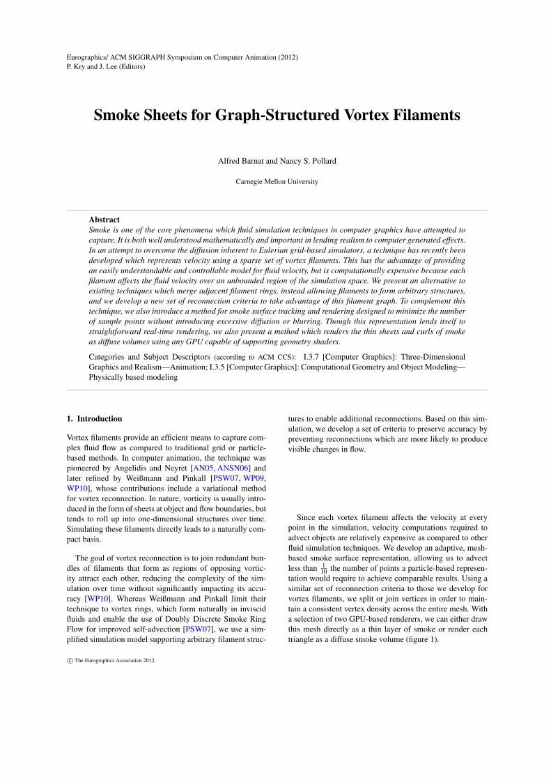
Figure 1: A high-resolution smoke plume with 439,934 ver-tices, simulated using a 719 vertex filament graph with 762edges.
2. Background
For general information on simulated fluids in graphics, werefer the reader to a recent survey paper and the referencestherein [TY09].
Much of the work in fluid animation over the past decadeis based on Stam’s Stable Fluids technique [Sta99], with theaddition of vorticity confinement [FSJ01], which attempts tocounteract velocity dissipation. Though well suited for con-fined environments, these techniques require prior knowl-edge and careful planning for application in open environ-ments, as the entire fluid domain must be discretized. Fur-thermore, even techniques which apply an adaptive gridspacing [LGF04] are unable to entirely eliminate velocitydissipation due to interpolation.
Smoothed Particle Hydrodynamics (SPH) offers an alter-native, where fluid state is associated with mobile particlesinstead of static grid coordinates [DG96, SF95]. By repre-senting the fluid domain as a collection of discrete particles,this and other Lagrangian methods avoid the need to prede-termine and discretize the region of space in which the sim-ulation will take place. However, SPH is best suited for thesimulation of a fluid which is mobile within a larger space,such as water surrounded by air, as it is difficult to preciselyfill an enclosed space with particles without either allowingholes in regions of high vorticity or reducing the stability ofthe simulation due to increased pressure.
Localized regions of vorticity have long been recognizedas important to the believability of a fluid simulation. Avariety of vorticity-preserving techniques have been devel-oped to slow the dissipation of these regions due to ve-locity diffusion [FSJ01, NSCL08, SRF05]. Simplical Flu-ids [ETK∗07] offers a mesh-based solution which preservescirculation by construction. However, even here the abilityto resolve these important structures of vorticity remainslimited by the sampling resolution of the simulation. Vor-tex particle formulations offer an alternative analogous toSPH [CCB∗08, GLG95, SRF05]. However, similar difficul-ties in information propagation arise, making them ill-suitedfor situations in which small timesteps are otherwise unnec-essary.
Angelidis and Neyret [AN05] pioneered the use of vortexfilaments as a simulation primitive for fluid animation. Sincefilaments of vorticity naturally form in a turbulent flow,a sparse filament basis is sufficient to approximate com-plex fluid motion. Pinkall et al. [PSW07] further developeda means to accurately model self-advection of discretizedpolygonal filaments, and Weißmann and Pinkall [WP10] in-troduced a physically motivated criteria for vortex reconnec-tion and hairpin removal. These techniques simulate onlyring-structured vortices.
The most direct means of simulating smoke is to storedensity values throughout the fluid domain, usually at thesame grid coordinates as the fluid velocity [FSJ01], and toadvect these values according to the fluid motion. However,this approach limits the minimum size of smoke featuresto the grid spacing and can cause aliasing artifacts if thisspacing is too large. Smoke particles can simulate fine-scaledetail [KW05], but dissipate quickly unless elongated andeventually split [AN05]. Funck et al. [FWTS08] use impliedconnectivity information to render smoke using sheets of ge-ometry with a particle at each vertex. Alternatively, geome-try can be constructed dynamically at each frame by joiningadjacent streams of particles [PSCN10]. However, neither ofthese methods modify particle placements or densities adap-tively as the simulation progresses.
Dynamic surface meshes have been used with great suc-cess for tracking both fine-scale features on fluid surfaces[WTGT09, TWGT10] and vortex sheets within a fluid, aseither the primary means of simulation [Sto06] or to addfine detail to a larger scale Eulerian simulation [PTG12].A variety of general use surface tracking techniques havebeen developed [CCB∗08, JCNH10], including the El Topolibrary [BB09b] which has proven effective for smoke an-imation [BB09a]. These techniques place a particular em-phasis on the maintenance of a valid physical interface inthe presence of topological changes, which is important formany applications. Such constraints are unnecessary in thecase of smoke, however, as the mesh tracks particle densitywithin a fluid.
c© The Eurographics Association 2012.
A. Barnat & N. S. Pollard / Smoke Sheets for Graph-Structured Vortex Filaments
3. Contributions
We develop a method of filament reconnection which at-tempts to preserve physical plausibility while allowing forthe maximum number of filament reconnections. Our ap-proach is motivated by visual accuracy of the results anddesigned to preserve a divergence-free vorticity graph.
Rather than enforcing ring-shaped structures of vorticity,we allow arbitrary reconnection between filaments of vary-ing strength, resulting in a directed graph of vortex filaments.This simplifies the overall technique while allowing us to re-duce the number of filament edges and vertices beyond pre-vious techniques.
We also explore the use of a triangle mesh with adaptivevertex spacing for smoke surface tracking. We use similarcriteria to those of our vortex reconnection technique to con-trol the vertex spacing within this mesh. Our system is ableto both dynamically re-mesh within a single layer and arbi-trarily reconnect multiple layers of smoke. In addition to thestraightforward direct rendering of this mesh, we present aGPU-based rendering technique which smoothes each trian-gle’s density according to an ellipsoidal gaussian kernel.
4. Physical Motivation
Our vortex filament based simulator allows for the construc-tion of any directed graph of filament edges. In regions ofcomplex flow, this structure bears a resemblance to the densevorticity mesh used by Simplical Fluids [ETK∗07], with thekey difference being that we advect the vertices themselvesrather than the values defined on the mesh.
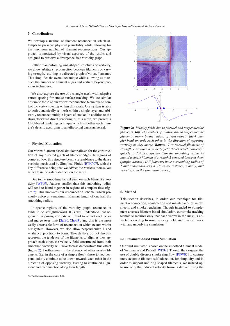
Due to the smoothing kernel used on each filament’s vor-ticity [WP09], features smaller than this smoothing radiuswill tend to blend together in regions of complex flow (fig-ure 2). This motivates our reconnection scheme, which pri-marily enforces a maximum filament length of one half thesmoothing radius.
In sparse regions of the vorticity graph, reconnectiontends to be straightforward. It is well understood that re-gions of opposing vorticity will tend to attract each otherand merge over time [Saf90, Cho93], and this is the mosteasily observable form of reconnection which occurs withinour system. However, we also allow perpendicular ⊥ and+ shaped junctions to form. Though they do not directlyrepresent the tendency of the filaments to align as they ap-proach each other, the velocity field constructed from theirsmoothed vorticity will nevertheless demonstrate this effect(figure 2). Furthermore, in the absence of other nearby fil-aments (i.e. in the case of a simple flow), those joined per-pendicularly continue to be drawn towards each other in thedirection of opposing vorticity, leading to continued align-ment and reconnection along their length.
-4 -3 -2 -1 0 1 2
-3
-2
-1
0
1
2
3
x
y
-4 -2 2 4
x
-2
-1
1
2
uz
Figure 2: Velocity fields due to parallel and perpendicularfilaments. Top: The centers of rotation due to perpendicularfilaments, shown by the regions of least velocity (dark pur-ple) bend towards each other in the direction of opposingvorticity as they merge. Bottom: Two parallel filaments ofstrength 1 produce a velocity field (blue) which convergesquickly at distances greater than the smoothing radius tothat of a single filament of strength 2 centered between them(purple, dashed). (All filaments have a smoothing radius of1 and unbounded length. Units are distance, x and y, andvelocity, uuu, in the simulation space.)
5. Method
This section describes, in order, our technique for fila-ment reconnection, construction and maintenance of smokesheets, and smoke rendering. Though intended to comple-ment a vortex filament based simulation, our smoke trackingtechnique requires only that each vertex in the mesh is ad-vected according to some velocity field, and thus can workwith any underlying simulation.
5.1. Filament-based Fluid Simulation
Our fluid simulator is based on the smoothed filament modelof Weißmann and Pinkall [WP09]. Though they suggest theuse of doubly discrete smoke ring flow [PSW07] to capturemore accurate filament self-advection, for simplicity and inorder to support non ring-shaped filaments, we instead optto use only the induced velocity formula derived using the
c© The Eurographics Association 2012.
A. Barnat & N. S. Pollard / Smoke Sheets for Graph-Structured Vortex Filaments
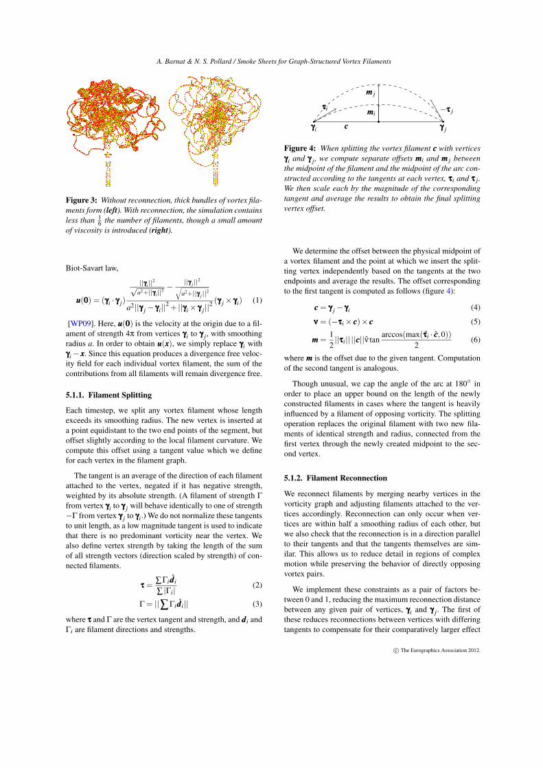
Figure 3: Without reconnection, thick bundles of vortex fila-ments form (left). With reconnection, the simulation containsless than 1
6 the number of filaments, though a small amountof viscosity is introduced (right).
Biot-Savart law,
uuu(000) = (γγγi · γγγ j)
||γγγi||2
√a2+||γγγi||
2 −||γγγ j||
2√a2+||γγγ j||
2
a2||γγγ j− γγγi||2 + ||γγγi× γγγ j||
2 (γγγ j× γγγi) (1)
[WP09]. Here, uuu(000) is the velocity at the origin due to a fil-ament of strength 4π from vertices γγγi to γγγ j, with smoothingradius a. In order to obtain uuu(xxx), we simply replace γγγi withγγγi− xxx. Since this equation produces a divergence free veloc-ity field for each individual vortex filament, the sum of thecontributions from all filaments will remain divergence free.
5.1.1. Filament Splitting
Each timestep, we split any vortex filament whose lengthexceeds its smoothing radius. The new vertex is inserted ata point equidistant to the two end points of the segment, butoffset slightly according to the local filament curvature. Wecompute this offset using a tangent value which we definefor each vertex in the filament graph.
The tangent is an average of the direction of each filamentattached to the vertex, negated if it has negative strength,weighted by its absolute strength. (A filament of strength Γ
from vertex γγγi to γγγ j will behave identically to one of strength−Γ from vertex γγγ j to γγγi.) We do not normalize these tangentsto unit length, as a low magnitude tangent is used to indicatethat there is no predominant vorticity near the vertex. Wealso define vertex strength by taking the length of the sumof all strength vectors (direction scaled by strength) of con-nected filaments.
τττ =∑Γidddi
∑ |Γi|(2)
Γ = ||∑Γidddi|| (3)
where τττ and Γ are the vertex tangent and strength, and dddi andΓi are filament directions and strengths.
τττi mmmi−τττ j
mmm j
γγγi γγγ jccc
Figure 4: When splitting the vortex filament ccc with verticesγγγi and γγγ j, we compute separate offsets mmmi and mmm j betweenthe midpoint of the filament and the midpoint of the arc con-structed according to the tangents at each vertex, τττi and τττ j.We then scale each by the magnitude of the correspondingtangent and average the results to obtain the final splittingvertex offset.
We determine the offset between the physical midpoint ofa vortex filament and the point at which we insert the split-ting vertex independently based on the tangents at the twoendpoints and average the results. The offset correspondingto the first tangent is computed as follows (figure 4):
ccc = γγγ j− γγγi (4)
ννν = (−τττi× ccc)× ccc (5)
mmm =12||τττi|| ||ccc||ν tan
arccos(max(τττi · ccc,0))2
(6)
where mmm is the offset due to the given tangent. Computationof the second tangent is analogous.
Though unusual, we cap the angle of the arc at 180◦ inorder to place an upper bound on the length of the newlyconstructed filaments in cases where the tangent is heavilyinfluenced by a filament of opposing vorticity. The splittingoperation replaces the original filament with two new fila-ments of identical strength and radius, connected from thefirst vertex through the newly created midpoint to the sec-ond vertex.
5.1.2. Filament Reconnection
We reconnect filaments by merging nearby vertices in thevorticity graph and adjusting filaments attached to the ver-tices accordingly. Reconnection can only occur when ver-tices are within half a smoothing radius of each other, butwe also check that the reconnection is in a direction parallelto their tangents and that the tangents themselves are sim-ilar. This allows us to reduce detail in regions of complexmotion while preserving the behavior of directly opposingvortex pairs.
We implement these constraints as a pair of factors be-tween 0 and 1, reducing the maximum reconnection distancebetween any given pair of vertices, γγγi and γγγ j. The first ofthese reduces reconnections between vertices with differingtangents to compensate for their comparatively larger effect
c© The Eurographics Association 2012.
A. Barnat & N. S. Pollard / Smoke Sheets for Graph-Structured Vortex Filaments
on local vorticity:
τττi · τττ j +12
. (7)
We then observe that reconnections which simply relo-cate a vertex along an existing filament will have no effecton the velocity field, whereas reconnections which movea vertex perpendicular to its connected filaments will havethe greatest effect. In order to limit the latter, we furtherscale the reconnection distance by the geometric mean ofthe dot products between the vertex tangents and the offsetbetween them, weighted by the magnitudes of their tangents(described in the previous section):
||τττi|| ||τττ j||
√√√√∣∣∣∣∣ (τττi · (γγγ j− γγγi))(τττ j · (γγγ j− γγγi))
||γγγ j− γγγi||2
∣∣∣∣∣+(1−||τττi|| ||τττ j||).
(8)
We merge vertices by averaging their positions, weightedby their aggregate strength. We then merge any filamentswhich become coincident by summing their strengths andaveraging their radii and we remove any filaments whichconnected the old vertices. This procedure ensures that thevorticity graph remains divergence free (i.e. the strength en-tering any vertex is equal to the strength exiting), as it isequivalent to simply moving the merged vertices to be coin-cident, modulo any difference in filament radii.
5.2. Smoke Sheets
Our smoke representation consists of an indexed trianglemesh with smoke density stored at each vertex. The den-sity is evenly distributed over the surrounding triangles, sothat the density per unit area at the vertex, which translatesloosely to absorbance, will change naturally as the area ofthe triangles changes.
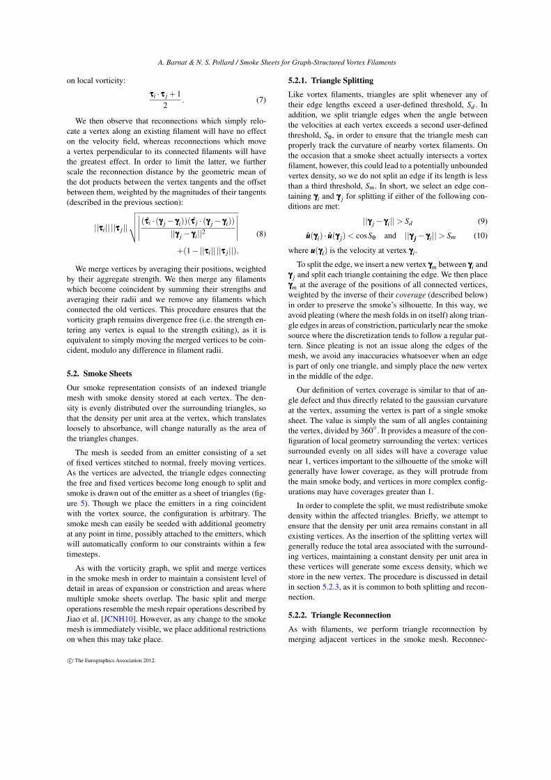
The mesh is seeded from an emitter consisting of a setof fixed vertices stitched to normal, freely moving vertices.As the vertices are advected, the triangle edges connectingthe free and fixed vertices become long enough to split andsmoke is drawn out of the emitter as a sheet of triangles (fig-ure 5). Though we place the emitters in a ring coincidentwith the vortex source, the configuration is arbitrary. Thesmoke mesh can easily be seeded with additional geometryat any point in time, possibly attached to the emitters, whichwill automatically conform to our constraints within a fewtimesteps.
As with the vorticity graph, we split and merge verticesin the smoke mesh in order to maintain a consistent level ofdetail in areas of expansion or constriction and areas wheremultiple smoke sheets overlap. The basic split and mergeoperations resemble the mesh repair operations described byJiao et al. [JCNH10]. However, as any change to the smokemesh is immediately visible, we place additional restrictionson when this may take place.
5.2.1. Triangle Splitting
Like vortex filaments, triangles are split whenever any oftheir edge lengths exceed a user-defined threshold, Sd . Inaddition, we split triangle edges when the angle betweenthe velocities at each vertex exceeds a second user-definedthreshold, Sθ, in order to ensure that the triangle mesh canproperly track the curvature of nearby vortex filaments. Onthe occasion that a smoke sheet actually intersects a vortexfilament, however, this could lead to a potentially unboundedvertex density, so we do not split an edge if its length is lessthan a third threshold, Sm. In short, we select an edge con-taining γγγi and γγγ j for splitting if either of the following con-ditions are met:
||γγγ j− γγγi||> Sd (9)
uuu(γγγi) · uuu(γγγ j)< cosSθ and ||γγγ jjj− γγγi||> Sm (10)
where uuu(γγγi) is the velocity at vertex γγγi.
To split the edge, we insert a new vertex γγγm between γγγi andγγγ j and split each triangle containing the edge. We then placeγγγm at the average of the positions of all connected vertices,weighted by the inverse of their coverage (described below)in order to preserve the smoke’s silhouette. In this way, weavoid pleating (where the mesh folds in on itself) along trian-gle edges in areas of constriction, particularly near the smokesource where the discretization tends to follow a regular pat-tern. Since pleating is not an issue along the edges of themesh, we avoid any inaccuracies whatsoever when an edgeis part of only one triangle, and simply place the new vertexin the middle of the edge.
Our definition of vertex coverage is similar to that of an-gle defect and thus directly related to the gaussian curvatureat the vertex, assuming the vertex is part of a single smokesheet. The value is simply the sum of all angles containingthe vertex, divided by 360◦. It provides a measure of the con-figuration of local geometry surrounding the vertex: verticessurrounded evenly on all sides will have a coverage valuenear 1, vertices important to the silhouette of the smoke willgenerally have lower coverage, as they will protrude fromthe main smoke body, and vertices in more complex config-urations may have coverages greater than 1.
In order to complete the split, we must redistribute smokedensity within the affected triangles. Briefly, we attempt toensure that the density per unit area remains constant in allexisting vertices. As the insertion of the splitting vertex willgenerally reduce the total area associated with the surround-ing vertices, maintaining a constant density per unit area inthese vertices will generate some excess density, which westore in the new vertex. The procedure is discussed in detailin section 5.2.3, as it is common to both splitting and recon-nection.
5.2.2. Triangle Reconnection
As with filaments, we perform triangle reconnection bymerging adjacent vertices in the smoke mesh. Reconnec-
c© The Eurographics Association 2012.
A. Barnat & N. S. Pollard / Smoke Sheets for Graph-Structured Vortex Filaments
Figure 5: The smoke source begins as a pair of coincident rings of vertices, one fixed and one advected with the fluid, whichform a cylindrical mesh as they are drawn apart. Once the edges are sufficiently long, our triangle splitting procedure beginsto insert additional vertices, allowing a smoke sheet to form.
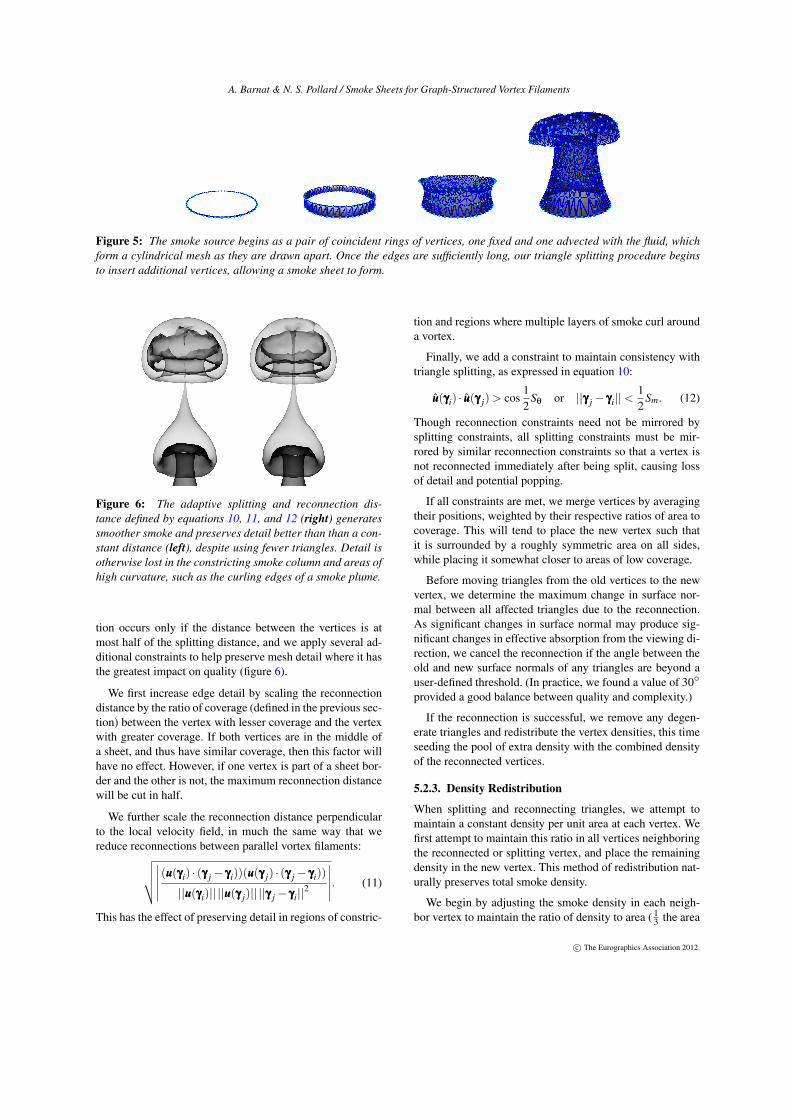
Figure 6: The adaptive splitting and reconnection dis-tance defined by equations 10, 11, and 12 (right) generatessmoother smoke and preserves detail better than than a con-stant distance (left), despite using fewer triangles. Detail isotherwise lost in the constricting smoke column and areas ofhigh curvature, such as the curling edges of a smoke plume.
tion occurs only if the distance between the vertices is atmost half of the splitting distance, and we apply several ad-ditional constraints to help preserve mesh detail where it hasthe greatest impact on quality (figure 6).
We first increase edge detail by scaling the reconnectiondistance by the ratio of coverage (defined in the previous sec-tion) between the vertex with lesser coverage and the vertexwith greater coverage. If both vertices are in the middle ofa sheet, and thus have similar coverage, then this factor willhave no effect. However, if one vertex is part of a sheet bor-der and the other is not, the maximum reconnection distancewill be cut in half.
We further scale the reconnection distance perpendicularto the local velocity field, in much the same way that wereduce reconnections between parallel vortex filaments:√√√√∣∣∣∣∣ (uuu(γγγi) · (γγγ j− γγγi))(uuu(γγγ j) · (γγγ j− γγγi))
||uuu(γγγi)|| ||uuu(γγγ j)|| ||γγγ j− γγγi||2
∣∣∣∣∣. (11)
This has the effect of preserving detail in regions of constric-
tion and regions where multiple layers of smoke curl arounda vortex.
Finally, we add a constraint to maintain consistency withtriangle splitting, as expressed in equation 10:
uuu(γγγi) · uuu(γγγ j)> cos12
Sθ or ||γγγ j− γγγi||<12
Sm. (12)
Though reconnection constraints need not be mirrored bysplitting constraints, all splitting constraints must be mir-rored by similar reconnection constraints so that a vertex isnot reconnected immediately after being split, causing lossof detail and potential popping.
If all constraints are met, we merge vertices by averagingtheir positions, weighted by their respective ratios of area tocoverage. This will tend to place the new vertex such thatit is surrounded by a roughly symmetric area on all sides,while placing it somewhat closer to areas of low coverage.
Before moving triangles from the old vertices to the newvertex, we determine the maximum change in surface nor-mal between all affected triangles due to the reconnection.As significant changes in surface normal may produce sig-nificant changes in effective absorption from the viewing di-rection, we cancel the reconnection if the angle between theold and new surface normals of any triangles are beyond auser-defined threshold. (In practice, we found a value of 30◦
provided a good balance between quality and complexity.)
If the reconnection is successful, we remove any degen-erate triangles and redistribute the vertex densities, this timeseeding the pool of extra density with the combined densityof the reconnected vertices.
5.2.3. Density Redistribution
When splitting and reconnecting triangles, we attempt tomaintain a constant density per unit area at each vertex. Wefirst attempt to maintain this ratio in all vertices neighboringthe reconnected or splitting vertex, and place the remainingdensity in the new vertex. This method of redistribution nat-urally preserves total smoke density.
We begin by adjusting the smoke density in each neigh-bor vertex to maintain the ratio of density to area ( 1
3 the area
c© The Eurographics Association 2012.
A. Barnat & N. S. Pollard / Smoke Sheets for Graph-Structured Vortex Filaments
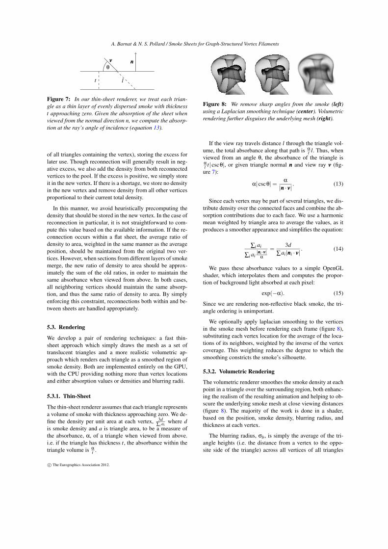
θ
nnnvvv
lt
Figure 7: In our thin-sheet renderer, we treat each trian-gle as a thin layer of evenly dispersed smoke with thicknesst approaching zero. Given the absorption of the sheet whenviewed from the normal direction n, we compute the absorp-tion at the ray’s angle of incidence (equation 13).
of all triangles containing the vertex), storing the excess forlater use. Though reconnection will generally result in neg-ative excess, we also add the density from both reconnectedvertices to the pool. If the excess is positive, we simply storeit in the new vertex. If there is a shortage, we store no densityin the new vertex and remove density from all other verticesproportional to their current total density.
In this manner, we avoid heuristically precomputing thedensity that should be stored in the new vertex. In the case ofreconnection in particular, it is not straightforward to com-pute this value based on the available information. If the re-connection occurs within a flat sheet, the average ratio ofdensity to area, weighted in the same manner as the averageposition, should be maintained from the original two ver-tices. However, when sections from different layers of smokemerge, the new ratio of density to area should be approx-imately the sum of the old ratios, in order to maintain thesame absorbance when viewed from above. In both cases,all neighboring vertices should maintain the same absorp-tion, and thus the same ratio of density to area. By simplyenforcing this constraint, reconnections both within and be-tween sheets are handled appropriately.
5.3. Rendering
We develop a pair of rendering techniques: a fast thin-sheet approach which simply draws the mesh as a set oftranslucent triangles and a more realistic volumetric ap-proach which renders each triangle as a smoothed region ofsmoke density. Both are implemented entirely on the GPU,with the CPU providing nothing more than vertex locationsand either absorption values or densities and blurring radii.
5.3.1. Thin-Sheet
The thin-sheet renderer assumes that each triangle representsa volume of smoke with thickness approaching zero. We de-fine the density per unit area at each vertex, 3d
∑i aiwhere d
is smoke density and a is triangle area, to be a measure ofthe absorbance, α, of a triangle when viewed from above.i.e. if the triangle has thickness t, the absorbance within thetriangle volume is α
t .
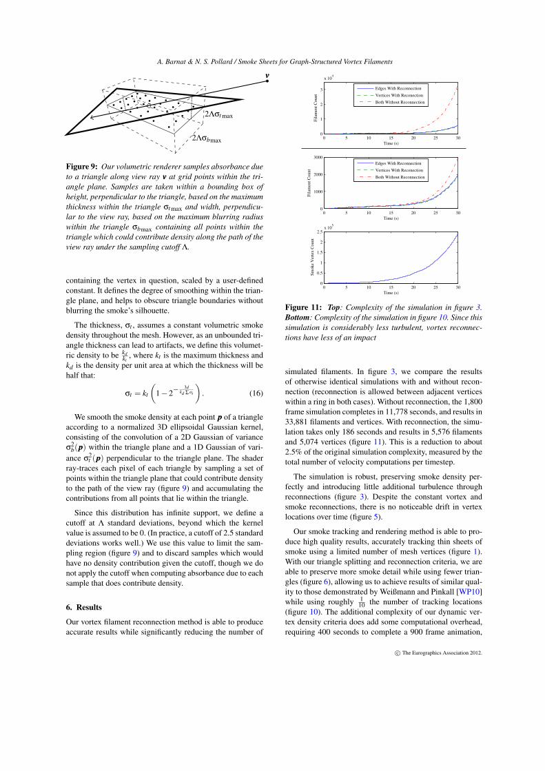
Figure 8: We remove sharp angles from the smoke (left)using a Laplacian smoothing technique (center). Volumetricrendering further disguises the underlying mesh (right).
If the view ray travels distance l through the triangle vol-ume, the total absorbance along that path is α
t l. Thus, whenviewed from an angle θ, the absorbance of the triangle isα
t t|cscθ|, or given triangle normal nnn and view ray vvv (fig-ure 7):
α|cscθ|= α
|nnn · vvv| . (13)
Since each vertex may be part of several triangles, we dis-tribute density over the connected faces and combine the ab-sorption contributions due to each face. We use a harmonicmean weighted by triangle area to average the values, as itproduces a smoother appearance and simplifies the equation:
∑i ai
∑i ai|nnni·vvv|
α
=3d
∑ai|nnni · vvv|. (14)
We pass these absorbance values to a simple OpenGLshader, which interpolates them and computes the propor-tion of background light absorbed at each pixel:
exp(−α). (15)
Since we are rendering non-reflective black smoke, the tri-angle ordering is unimportant.
We optionally apply laplacian smoothing to the verticesin the smoke mesh before rendering each frame (figure 8),substituting each vertex location for the average of the loca-tions of its neighbors, weighted by the inverse of the vertexcoverage. This weighting reduces the degree to which thesmoothing constricts the smoke’s silhouette.
5.3.2. Volumetric Rendering
The volumetric renderer smoothes the smoke density at eachpoint in a triangle over the surrounding region, both enhanc-ing the realism of the resulting animation and helping to ob-scure the underlying smoke mesh at close viewing distances(figure 8). The majority of the work is done in a shader,based on the position, smoke density, blurring radius, andthickness at each vertex.
The blurring radius, σb, is simply the average of the tri-angle heights (i.e. the distance from a vertex to the oppo-site side of the triangle) across all vertices of all triangles
c© The Eurographics Association 2012.
A. Barnat & N. S. Pollard / Smoke Sheets for Graph-Structured Vortex Filaments
vvv
2Λσbmax
2Λσt max
Figure 9: Our volumetric renderer samples absorbance dueto a triangle along view ray vvv at grid points within the tri-angle plane. Samples are taken within a bounding box ofheight, perpendicular to the triangle, based on the maximumthickness within the triangle σt max and width, perpendicu-lar to the view ray, based on the maximum blurring radiuswithin the triangle σbmax containing all points within thetriangle which could contribute density along the path of theview ray under the sampling cutoff Λ.
containing the vertex in question, scaled by a user-definedconstant. It defines the degree of smoothing within the trian-gle plane, and helps to obscure triangle boundaries withoutblurring the smoke’s silhouette.
The thickness, σt , assumes a constant volumetric smokedensity throughout the mesh. However, as an unbounded tri-angle thickness can lead to artifacts, we define this volumet-ric density to be kd
kt, where kt is the maximum thickness and
kd is the density per unit area at which the thickness will behalf that:
σt = kt
(1−2−
3dkd ∑ ai
). (16)
We smooth the smoke density at each point ppp of a triangleaccording to a normalized 3D ellipsoidal Gaussian kernel,consisting of the convolution of a 2D Gaussian of varianceσ
2b(ppp) within the triangle plane and a 1D Gaussian of vari-
ance σ2t (ppp) perpendicular to the triangle plane. The shader
ray-traces each pixel of each triangle by sampling a set ofpoints within the triangle plane that could contribute densityto the path of the view ray (figure 9) and accumulating thecontributions from all points that lie within the triangle.
Since this distribution has infinite support, we define acutoff at Λ standard deviations, beyond which the kernelvalue is assumed to be 0. (In practice, a cutoff of 2.5 standarddeviations works well.) We use this value to limit the sam-pling region (figure 9) and to discard samples which wouldhave no density contribution given the cutoff, though we donot apply the cutoff when computing absorbance due to eachsample that does contribute density.
6. Results
Our vortex filament reconnection method is able to produceaccurate results while significantly reducing the number of
0 5 10 15 20 25 300
1
2
3
x 104
Time (s)
Fil
amen
t C
ou
nt
Edges With Reconnection
Vertices With Reconection
Both Without Reconnection
0 5 10 15 20 25 300
1000
2000
3000
Time (s)
Fil
amen
t C
ou
nt
Edges With Reconnection
Vertices With Reconection
Both Without Reconnection
0 5 10 15 20 25 300
0.5
1
1.5
2
2.5x 10
5
Time (s)
Sm
oke V
ert
ex
Cou
nt
Figure 11: Top: Complexity of the simulation in figure 3.Bottom: Complexity of the simulation in figure 10. Since thissimulation is considerably less turbulent, vortex reconnec-tions have less of an impact
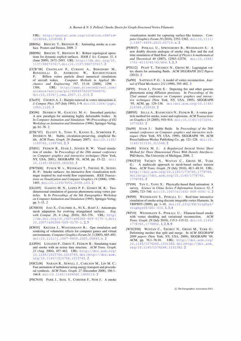
simulated filaments. In figure 3, we compare the resultsof otherwise identical simulations with and without recon-nection (reconnection is allowed between adjacent verticeswithin a ring in both cases). Without reconnection, the 1,800frame simulation completes in 11,778 seconds, and results in33,881 filaments and vertices. With reconnection, the simu-lation takes only 186 seconds and results in 5,576 filamentsand 5,074 vertices (figure 11). This is a reduction to about2.5% of the original simulation complexity, measured by thetotal number of velocity computations per timestep.
The simulation is robust, preserving smoke density per-fectly and introducing little additional turbulence throughreconnections (figure 3). Despite the constant vortex andsmoke reconnections, there is no noticeable drift in vertexlocations over time (figure 5).
Our smoke tracking and rendering method is able to pro-duce high quality results, accurately tracking thin sheets ofsmoke using a limited number of mesh vertices (figure 1).With our triangle splitting and reconnection criteria, we areable to preserve more smoke detail while using fewer trian-gles (figure 6), allowing us to achieve results of similar qual-ity to those demonstrated by Weißmann and Pinkall [WP10]while using roughly 1
10 the number of tracking locations(figure 10). The additional complexity of our dynamic ver-tex density criteria does add some computational overhead,requiring 400 seconds to complete a 900 frame animation,
c© The Eurographics Association 2012.

A. Barnat & N. S. Pollard / Smoke Sheets for Graph-Structured Vortex Filaments
Figure 10: A snapshot of the 1,500th frame of a 30 second, 1,800 frame simulation showing the blurred density (left), vortexfilaments and smoothed density (center), and triangle edges (right). The smoke mesh contains 108,711 vertices, and the vorticitygraph contains 656 vertices and 694 edges.
as opposed to 300 with a constant density. However, as thisoverhead is constant in the number of vortex filaments, it isdominated by velocity computation in longer simulations.
Though our volumetric renderer is slower than real-timefor smoke meshes of any significant size, the complexity islinear in the number of triangles, and thus will always even-tually be exceeded by simulation time. After one second ofsimulation at high output resolution and moderate smokevertex density (figure 10), rendering takes approximately 19times longer than simulation, or 0.079 seconds as opposed to0.0041 seconds per frame. However, by the end of the simu-lation, rendering takes 38 seconds while the simulation itselftakes 120 seconds per frame. Cumulatively, 21,827 secondsare spent on simulation and 13,007 on rendering for the 30second, 1,800 frame animation.
7. Discussion
In this paper, we introduce both an extension to existing vor-tex filament based fluid simulation techniques and a smoketracking and rendering system designed to reduce the num-ber of velocity computations required to achieve a givenlevel of detail over commonly used particle-based tech-niques. Our fluid simulator is able to retain a high degree ofphysical realism while significantly reducing the total num-ber of filaments through reconnection, and our smoke track-ing technique is able to preserve thin, sheet-like formationsusing far fewer points than would be required by existingparticle-based systems. Coupled with the volumetric ren-derer, our system is capable of producing highly detailed,realistic smoke animations using a limited number of fila-ment and smoke vertices.
Though we have shown that a visually inspired approachto reconnection can lead to plausible results, further im-
provement may be possible by directly bounding the changein velocity due to reconnection, much as Weißmann andPinkall [WP10] do in cases where the difference in vortic-ity takes the form of a closed filament loop.
Looking at our smoke tracking system, we may be able tofurther improve results by tracking additional information inthe smoke mesh. For instance we could more accurately dis-tribute density during rendering if we knew that one trianglerepresented two recently reconnected sheets while others,sharing a vertex, were part of only one of those sheets. Sep-arately, as an extension to volumetric rendering, we mighttrack density dissipation at each vertex, increasing trianglethicknesses and blurring radii over time.
Both filament-based fluids and mesh-based smoke havethe potential to enable styles and effects which are not wellsupported by other simulation and rendering techniques.With the exception of volumetric rendering, the greatest po-tential may be for real-time applications. Each technique de-grades well in quality with reduced complexity and, moreimportantly, the complexity depends only on the number offeatures currently being simulated, not the total capacity ofthe simulation environment.
References[AN05] ANGELIDIS A., NEYRET F.: Simulation of smoke based
on vortex filament primitives. In Proceedings of the 2005 ACMSIGGRAPH/Eurographics symposium on Computer animation(New York, NY, USA, 2005), SCA ’05, ACM, pp. 87–96. doi:10.1145/1073368.1073380. 1, 2
[ANSN06] ANGELIDIS A., NEYRET F., SINGH K.,NOWROUZEZAHRAI D.: A controllable, fast and stablebasis for vortex based smoke simulation. In Proceedingsof the 2006 ACM SIGGRAPH/Eurographics Symposium onComputer Animation (Aire-la-Ville, Switzerland, Switzer-land, 2006), SCA ’06, Eurographics Association, pp. 25–32.
c© The Eurographics Association 2012.
A. Barnat & N. S. Pollard / Smoke Sheets for Graph-Structured Vortex Filaments
URL: http://portal.acm.org/citation.cfm?id=1218064.1218068. 1
[BB09a] BROCHU T., BRIDSON R.: Animating smoke as a sur-face. Posters and Demos, 2009. 2
[BB09b] BROCHU T., BRIDSON R.: Robust topological opera-tions for dynamic explicit surfaces. SIAM J. Sci. Comput. 31, 4(June 2009), 2472–2493. URL: http://dx.doi.org/10.1137/080737617, doi:10.1137/080737617. 2
[CCB∗08] CHATELAIN P., CURIONI A., BERGDORF M.,ROSSINELLI D., ANDREONI W., KOUMOUTSAKOSP.: Billion vortex particle direct numerical simulationsof aircraft wakes. Computer Methods in Applied Me-chanics and Engineering 197, 13-16 (2008), 1296 –1304. URL: http://www.sciencedirect.com/science/article/pii/S0045782507004574,doi:10.1016/j.cma.2007.11.016. 2
[Cho93] CHORIN A. J.: Hairpin removal in vortex interactions ii.J. Comput. Phys. 107 (July 1993), 1–9. doi:10.1006/jcph.1993.1120. 3
[DG96] DESBRUN M., GASCUEL M.-P.: Smoothed particles:A new paradigm for animating highly deformable bodies. InIn Computer Animation and Simulation ’96 (Proceedings of EGWorkshop on Animation and Simulation (1996), Springer-Verlag,pp. 61–76. 2
[ETK∗07] ELCOTT S., TONG Y., KANSO E., SCHRÖDER P.,DESBRUN M.: Stable, circulation-preserving, simplicial flu-ids. ACM Trans. Graph. 26 (January 2007). doi:10.1145/1189762.1189766. 2, 3
[FSJ01] FEDKIW R., STAM J., JENSEN H. W.: Visual simula-tion of smoke. In Proceedings of the 28th annual conferenceon Computer graphics and interactive techniques (New York,NY, USA, 2001), SIGGRAPH ’01, ACM, pp. 15–22. doi:10.1145/383259.383260. 2
[FWTS08] FUNCK W. V., WEINKAUF T., THEISEL H., SEIDELH.-P.: Smoke surfaces: An interactive flow visualization tech-nique inspired by real-world flow experiments. IEEE Transac-tions on Visualization and Computer Graphics 14 (2008), 1396–1403. doi:10.1109/TVCG.2008.163. 2
[GLG95] GAMITO M. N., LOPES P. F., GOMES M. R.: Two-dimensional simulation of gaseous phenomena using vortex par-ticles. In In Proceedings of the 6th Eurographics Workshopon Computer Animation and Simulation (1995), Springer-Verlag,pp. 3–15. 2
[JCNH10] JIAO X., COLOMBI A., NI X., HART J.: Anisotropicmesh adaptation for evolving triangulated surfaces. Eng.with Comput. 26, 4 (Aug. 2010), 363–376. URL: http://dx.doi.org/10.1007/s00366-009-0170-1, doi:10.1007/s00366-009-0170-1. 2, 5
[KW05] KRÜGER J., WESTERMANN R.: Gpu simulation andrendering of volumetric effects for computer games and virtualenvironments. Computer Graphics Forum 24, 3 (2005), 685–693.doi:10.1111/j.1467-8659.2005.00893.x. 2
[LGF04] LOSASSO F., GIBOU F., FEDKIW R.: Simulating waterand smoke with an octree data structure. ACM Trans. Graph.23 (Aug. 2004), 457–462. URL: http://doi.acm.org/10.1145/1015706.1015745, doi:http://doi.acm.org/10.1145/1015706.1015745. 2
[NSCL08] NARAIN R., SEWALL J., CARLSON M., LIN M. C.:Fast animation of turbulence using energy transport and procedu-ral synthesis. ACM Trans. Graph. 27 (December 2008), 166:1–166:8. doi:10.1145/1409060.1409119. 2
[PSCN10] PARK J., SEOL Y., CORDIER F., NOH J.: A smoke
visualization model for capturing surface-like features. Com-puter Graphics Forum 29 (2010), 2352–2362. doi:10.1111/j.1467-8659.2010.01719.x. 2
[PSW07] PINKALL U., SPRINGBORN B., WEISSMANN S.: Anew doubly discrete analogue of smoke ring flow and the realtime simulation of fluid flow. Journal of Physics A-mathematicaland Theoretical 40 (2007), 12563–12576. doi:10.1088/1751-8113/40/42/S04. 1, 2, 3
[PTG12] PFAFF T., THUEREY N., GROSS M.: Lagrangian vor-tex sheets for animating fluids. ACM SIGGRAPH 2012 Papers(2012). 2
[Saf90] SAFFMAN P. G.: A model of vortex reconnection. Jour-nal of Fluid Mechanics 212 (1990), 395–402. 3
[SF95] STAM J., FIUME E.: Depicting fire and other gaseousphenomena using diffusion processes. In Proceedings of the22nd annual conference on Computer graphics and interac-tive techniques (New York, NY, USA, 1995), SIGGRAPH’95, ACM, pp. 129–136. doi:doi.acm.org/10.1145/218380.218430. 2
[SRF05] SELLE A., RASMUSSEN N., FEDKIW R.: A vortex par-ticle method for smoke, water and explosions. ACM Transactionson Graphics 24 (2005), 910–914. doi:10.1145/1073204.1073282. 2
[Sta99] STAM J.: Stable fluids. In Proceedings of the 26thannual conference on Computer graphics and interactive tech-niques (New York, NY, USA, 1999), SIGGRAPH ’99, ACMPress/Addison-Wesley Publishing Co., pp. 121–128. doi:10.1145/311535.311548. 2
[Sto06] STOCK M. J.: A Regularized Inviscid Vortex SheetMethod for Three Dimensional Flows With Density Interfaces.PhD thesis, The University of Michigan, 2006. 2
[TWGT10] THÜREY N., WOJTAN C., GROSS M., TURKG.: A multiscale approach to mesh-based surface tensionflows. ACM Trans. Graph. 29 (July 2010), 48:1–48:10. URL:http://doi.acm.org/10.1145/1778765.1778785,doi:http://doi.acm.org/10.1145/1778765.1778785. 2
[TY09] TAN J., YANG X.: Physically-based fluid animation: Asurvey. Science in China Series F-Information Sciences 52, 5(2009), 723–740. doi:10.1007/s11432-009-0091-z. 2
[WP09] WEISSMANN S., PINKALL U.: Real-time interactivesimulation of smoke using discrete integrable vortex filaments. InVRIPHYS (2009), pp. 1–10. doi:10.2312/PE/vriphys/vriphys09/001-010. 1, 3, 4
[WP10] WEISSMANN S., PINKALL U.: Filament-based smokewith vortex shedding and variational reconnection. ACMTrans. Graph. 29 (July 2010), 115:1–115:12. doi:10.1145/1778765.1778852. 1, 2, 8, 9
[WTGT09] WOJTAN C., THÜREY N., GROSS M., TURK G.:Deforming meshes that split and merge. In ACM SIGGRAPH2009 papers (New York, NY, USA, 2009), SIGGRAPH ’09,ACM, pp. 76:1–76:10. URL: http://doi.acm.org/10.1145/1576246.1531382, doi:http://doi.acm.org/10.1145/1576246.1531382. 2
c© The Eurographics Association 2012.


![SCA2012-02[1] Copy](https://img.pdfslide.net/doc/110x75/577cd6ef1a28ab9e789d9a5c/sca2012-021-copy.jpg)