Embed Size (px)
Citation preview
NATIONAL SYNCHROTRON LIGHT SOURCE II BROOKHAVEN NATIONAL LABORATORY BROOKHAVEN SCIENCE ASSOCIATES
UPTON, LONG ISLAND, N.Y. 11973
PROJECT:
SMI Beamline Instrument Readiness Functional Description
Page 1 of 13 NSLSII-12ID-RPT-001 14Oct2016 1
DATE VERSION
Soft Matter Interfaces (SMI) Beamline IRR Functional Description
NATIONAL SYNCHROTRON LIGHT SOURCE II BROOKHAVEN NATIONAL LABORATORY BROOKHAVEN SCIENCE ASSOCIATES
UPTON, LONG ISLAND, N.Y. 11973
PROJECT:
SMI Beamline Instrument Readiness Functional Description
Page 2 of 13 NSLSII-12ID-RPT-001 14Oct2016 1
DATE VERSION
Contents
1 1 INTRODUCTION .......................................................................................................................................................... 3
1.1 Primary Research Capabilities ............................................................................................................................. 3 1.2 Beamline Staff ...................................................................................................................................................... 4
2 BEAMLINE DESIGN AND COMPONENTS .................................................................................................................... 4
2.1 Beamline Performance Goals .............................................................................................................................. 4
2.2 Beamline Layout ................................................................................................................................................... 4
3 RADIATION SAFETY AND PERSONNEL PROTECTION SYSTEMS ........................................................................... 7
3.1 Radiation Enclosures and Shielding .................................................................................................................... 7 3.2 Radiation Safety Components ............................................................................................................................. 7
3.3 Thermal Management .......................................................................................................................................... 8
3.4 Gaseous Bremsstralhung Management ............................................................................................................... 9
3.5 Configuration Control .........................................................................................................................................10
3.6 Area Radiation Monitors .....................................................................................................................................10
3.7 Oxygen Sensors .................................................................................................................................................10 3.8 Personnel Protection system (PPS) ...................................................................................................................10
4 4 INSTRUMENT READINESS ......................................................................................................................................11
4.1 Survey and alignment.........................................................................................................................................11
4.2 Utilities ................................................................................................................................................................11
4.3 Vacuum System and Pressure Safety ...............................................................................................................11 4.3.1 Common Branch Vacuum Sections ......................................................................................................11 4.3.2 Inboard Branch Beam Transport Vacuum Sections ..............................................................................11 4.3.3 GISAXS/WAXS Experiment Vacuum Sections .....................................................................................12
4.4 Controls ..............................................................................................................................................................12
4.5 Equipment Protection System (EPS) .................................................................................................................12
Page 3 of 13
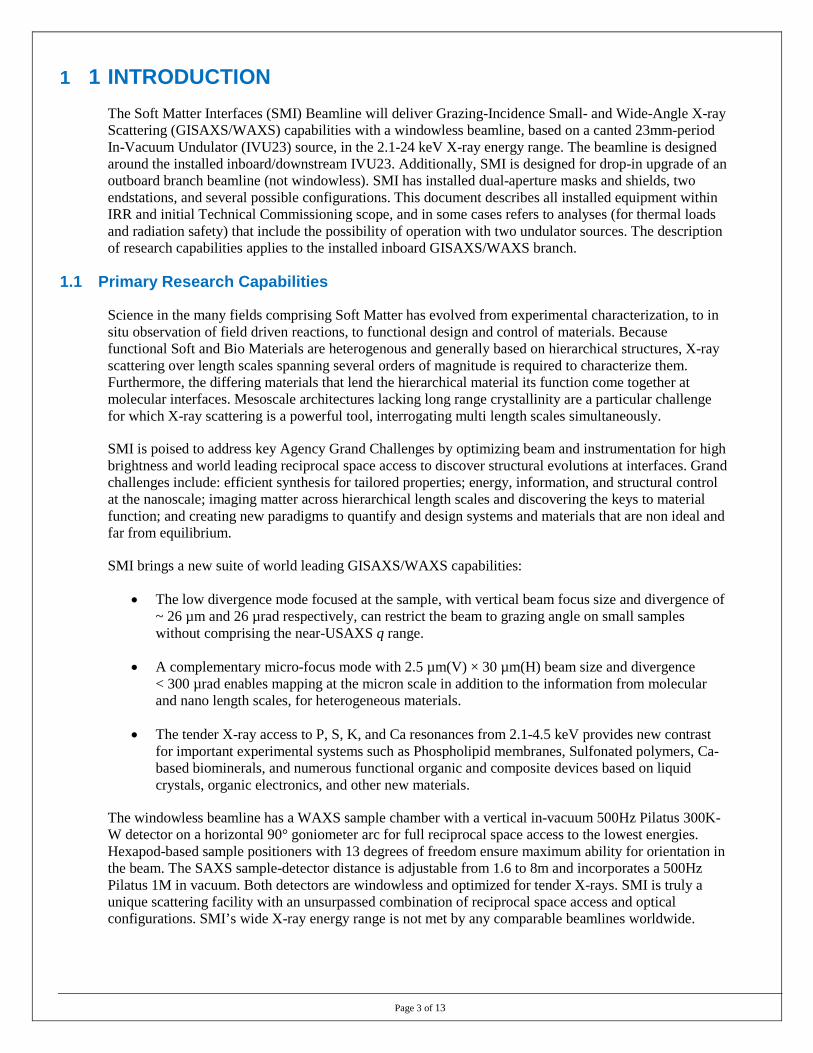
1 1 INTRODUCTION The Soft Matter Interfaces (SMI) Beamline will deliver Grazing-Incidence Small- and Wide-Angle X-ray Scattering (GISAXS/WAXS) capabilities with a windowless beamline, based on a canted 23mm-period In-Vacuum Undulator (IVU23) source, in the 2.1-24 keV X-ray energy range. The beamline is designed around the installed inboard/downstream IVU23. Additionally, SMI is designed for drop-in upgrade of an outboard branch beamline (not windowless). SMI has installed dual-aperture masks and shields, two endstations, and several possible configurations. This document describes all installed equipment within IRR and initial Technical Commissioning scope, and in some cases refers to analyses (for thermal loads and radiation safety) that include the possibility of operation with two undulator sources. The description of research capabilities applies to the installed inboard GISAXS/WAXS branch.
1.1 Primary Research Capabilities
Science in the many fields comprising Soft Matter has evolved from experimental characterization, to in situ observation of field driven reactions, to functional design and control of materials. Because functional Soft and Bio Materials are heterogenous and generally based on hierarchical structures, X-ray scattering over length scales spanning several orders of magnitude is required to characterize them. Furthermore, the differing materials that lend the hierarchical material its function come together at molecular interfaces. Mesoscale architectures lacking long range crystallinity are a particular challenge for which X-ray scattering is a powerful tool, interrogating multi length scales simultaneously.
SMI is poised to address key Agency Grand Challenges by optimizing beam and instrumentation for high brightness and world leading reciprocal space access to discover structural evolutions at interfaces. Grand challenges include: efficient synthesis for tailored properties; energy, information, and structural control at the nanoscale; imaging matter across hierarchical length scales and discovering the keys to material function; and creating new paradigms to quantify and design systems and materials that are non ideal and far from equilibrium.
SMI brings a new suite of world leading GISAXS/WAXS capabilities:
• The low divergence mode focused at the sample, with vertical beam focus size and divergence of ~ 26 µm and 26 µrad respectively, can restrict the beam to grazing angle on small samples without comprising the near-USAXS q range.
• A complementary micro-focus mode with 2.5 µm(V) × 30 µm(H) beam size and divergence < 300 µrad enables mapping at the micron scale in addition to the information from molecular and nano length scales, for heterogeneous materials.
• The tender X-ray access to P, S, K, and Ca resonances from 2.1-4.5 keV provides new contrast for important experimental systems such as Phospholipid membranes, Sulfonated polymers, Ca-based biominerals, and numerous functional organic and composite devices based on liquid crystals, organic electronics, and other new materials.
The windowless beamline has a WAXS sample chamber with a vertical in-vacuum 500Hz Pilatus 300K-W detector on a horizontal 90° goniometer arc for full reciprocal space access to the lowest energies. Hexapod-based sample positioners with 13 degrees of freedom ensure maximum ability for orientation in the beam. The SAXS sample-detector distance is adjustable from 1.6 to 8m and incorporates a 500Hz Pilatus 1M in vacuum. Both detectors are windowless and optimized for tender X-rays. SMI is truly a unique scattering facility with an unsurpassed combination of reciprocal space access and optical configurations. SMI’s wide X-ray energy range is not met by any comparable beamlines worldwide.
Page 4 of 13
1.2 Beamline Staff
Lead Beamline Scientist/ CSM Elaine DiMasi
Authorized Beamline Staff Mikhail Zhernenkov Assoc. Beamline Scientist Richard Greene Mechanical Technician Sung-Leung So Controls Engineer
Beamline Support Staff Daniel Bacescu Mechanical Engineer David Scott Coburn Mechanical Engineer
2 BEAMLINE DESIGN AND COMPONENTS 2.1 Beamline Performance Goals
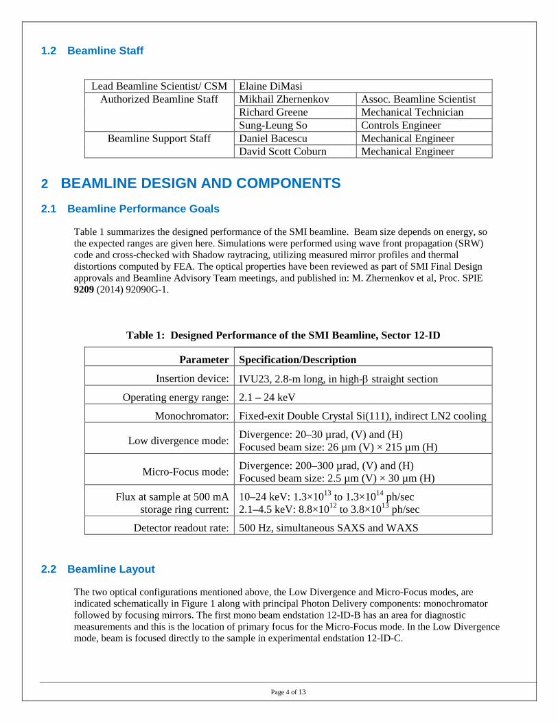
Table 1 summarizes the designed performance of the SMI beamline. Beam size depends on energy, so the expected ranges are given here. Simulations were performed using wave front propagation (SRW) code and cross-checked with Shadow raytracing, utilizing measured mirror profiles and thermal distortions computed by FEA. The optical properties have been reviewed as part of SMI Final Design approvals and Beamline Advisory Team meetings, and published in: M. Zhernenkov et al, Proc. SPIE 9209 (2014) 92090G-1.
Table 1: Designed Performance of the SMI Beamline, Sector 12-ID
Parameter Specification/Description
Insertion device: IVU23, 2.8-m long, in high-β straight section
Operating energy range: 2.1 – 24 keV
Monochromator: Fixed-exit Double Crystal Si(111), indirect LN2 cooling
Low divergence mode: Divergence: 20–30 µrad, (V) and (H) Focused beam size: 26 µm (V) × 215 µm (H)
Micro-Focus mode: Divergence: 200–300 µrad, (V) and (H) Focused beam size: 2.5 µm (V) × 30 µm (H)
Flux at sample at 500 mA storage ring current:
10–24 keV: 1.3×10¹³ to 1.3×10¹⁴ ph/sec 2.1–4.5 keV: 8.8×10¹² to 3.8×10¹³ ph/sec
Detector readout rate: 500 Hz, simultaneous SAXS and WAXS
2.2 Beamline Layout
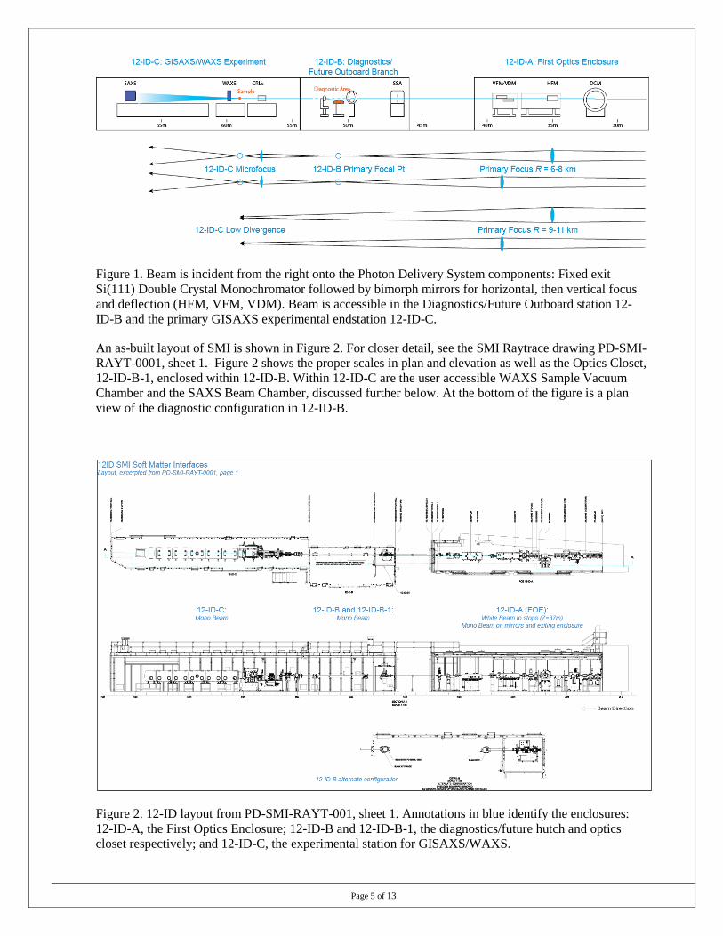
The two optical configurations mentioned above, the Low Divergence and Micro-Focus modes, are indicated schematically in Figure 1 along with principal Photon Delivery components: monochromator followed by focusing mirrors. The first mono beam endstation 12-ID-B has an area for diagnostic measurements and this is the location of primary focus for the Micro-Focus mode. In the Low Divergence mode, beam is focused directly to the sample in experimental endstation 12-ID-C.
Page 5 of 13
Figure 1. Beam is incident from the right onto the Photon Delivery System components: Fixed exit Si(111) Double Crystal Monochromator followed by bimorph mirrors for horizontal, then vertical focus and deflection (HFM, VFM, VDM). Beam is accessible in the Diagnostics/Future Outboard station 12-ID-B and the primary GISAXS experimental endstation 12-ID-C.
An as-built layout of SMI is shown in Figure 2. For closer detail, see the SMI Raytrace drawing PD-SMI-RAYT-0001, sheet 1. Figure 2 shows the proper scales in plan and elevation as well as the Optics Closet, 12-ID-B-1, enclosed within 12-ID-B. Within 12-ID-C are the user accessible WAXS Sample Vacuum Chamber and the SAXS Beam Chamber, discussed further below. At the bottom of the figure is a plan view of the diagnostic configuration in 12-ID-B.
Figure 2. 12-ID layout from PD-SMI-RAYT-001, sheet 1. Annotations in blue identify the enclosures: 12-ID-A, the First Optics Enclosure; 12-ID-B and 12-ID-B-1, the diagnostics/future hutch and optics closet respectively; and 12-ID-C, the experimental station for GISAXS/WAXS.
Page 6 of 13
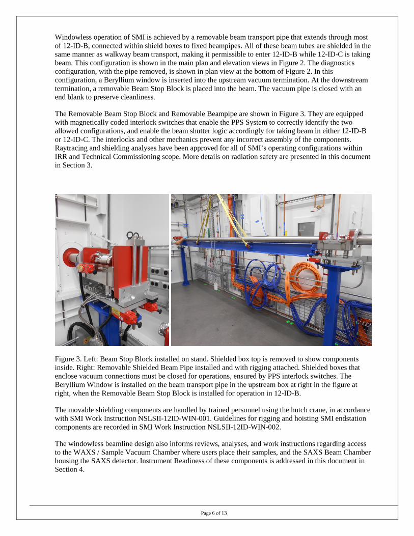
Windowless operation of SMI is achieved by a removable beam transport pipe that extends through most of 12-ID-B, connected within shield boxes to fixed beampipes. All of these beam tubes are shielded in the same manner as walkway beam transport, making it permissible to enter 12-ID-B while 12-ID-C is taking beam. This configuration is shown in the main plan and elevation views in Figure 2. The diagnostics configuration, with the pipe removed, is shown in plan view at the bottom of Figure 2. In this configuration, a Beryllium window is inserted into the upstream vacuum termination. At the downstream termination, a removable Beam Stop Block is placed into the beam. The vacuum pipe is closed with an end blank to preserve cleanliness.
The Removable Beam Stop Block and Removable Beampipe are shown in Figure 3. They are equipped with magnetically coded interlock switches that enable the PPS System to correctly identify the two allowed configurations, and enable the beam shutter logic accordingly for taking beam in either 12-ID-B or 12-ID-C. The interlocks and other mechanics prevent any incorrect assembly of the components. Raytracing and shielding analyses have been approved for all of SMI’s operating configurations within IRR and Technical Commissioning scope. More details on radiation safety are presented in this document in Section 3.
Figure 3. Left: Beam Stop Block installed on stand. Shielded box top is removed to show components inside. Right: Removable Shielded Beam Pipe installed and with rigging attached. Shielded boxes that enclose vacuum connections must be closed for operations, ensured by PPS interlock switches. The Beryllium Window is installed on the beam transport pipe in the upstream box at right in the figure at right, when the Removable Beam Stop Block is installed for operation in 12-ID-B.
The movable shielding components are handled by trained personnel using the hutch crane, in accordance with SMI Work Instruction NSLSII-12ID-WIN-001. Guidelines for rigging and hoisting SMI endstation components are recorded in SMI Work Instruction NSLSII-12ID-WIN-002.
The windowless beamline design also informs reviews, analyses, and work instructions regarding access to the WAXS / Sample Vacuum Chamber where users place their samples, and the SAXS Beam Chamber housing the SAXS detector. Instrument Readiness of these components is addressed in this document in Section 4.
Page 7 of 13
3 RADIATION SAFETY AND PERSONNEL PROTECTION SYSTEMS
3.1 Radiation Enclosures and Shielding
Radiation shielding design at NSLS-II follows strict guidelines to reduce radiation levels outside beamline enclosures to as low as reasonably achievable. Division guidelines as applied to SMI are documented in “12-ID SMI Beamline Radiation Shielding Analysis,” NSLS-II Technical Note 228. As explained in the analysis report, the recommended shielding is based on calculations to achieve dose rates less than 0.05 mrem/hr in continuously occupied areas and less than 0.5 mrem/hr on contact with the downstream wall of the First Optical Enclosure during normal operations.
The SMI FOE, a white beam enclosure, has been constructed with 18 mm Pb on the lateral wall, 50 mm Pb on the downstream wall, and 10 mm Pb on the roof. Enclosures 12-ID-A and 12-ID-B, for monochromatic x-rays from the IVU source, are constructed with 6 mm thick steel walls and ceilings.
Shielded beam transport consists of 68 mm diameter steel tubing (2mm thick wall) wrapped with 5mm Pb, wrapped outside with steel shim to protect the surface. Pb beam stop blocks in the monochromatic beam hutches are 25 mm thick. The removable shielded beam pipe has the same characteristics as all fixed shielded beam pipe, with equal or greater shielding on the shielded boxes and at all hutch wall beam pipe penetrations (guillotines). All guillotines and block-shaped shields are either continuous in the plane normal to the beam path or have chicane/chevron profiles to guarantee that no radiation path through the shielding sees any reduction of path length to a value below the specification.
A monochromatic beam shutter of the standard NSLS-II design is the final component in the downstream end of 12-ID-A.
3.2 Radiation Safety Components
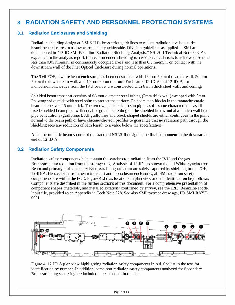
Radiation safety components help contain the synchrotron radiation from the IVU and the gas Bremsstrahlung radiation from the storage ring. Analysis of 12-ID has shown that all White Synchrotron Beam and primary and secondary Bremsstrahlung radiation are safely captured by shielding in the FOE, 12-ID-A. Hence, aside from beam transport and mono beam enclosures, all SMI radiation safety components are within the FOE. Figure 4 shows locations in plan view and an identification key follows. Components are described in the further sections of this document. For a comprehensive presentation of component shapes, materials, and installed locations confirmed by survey, see the 12ID Beamline Model Input file, provided as an Appendix in Tech Note 228. See also SMI raytrace drawings, PD-SMI-RAYT-0001.
Figure 4. 12-ID-A plan view highlighting radiation safety components in red. See list in the text for identification by number. In addition, some non-radiation safety components analyzed for Secondary Bremsstrahlung scattering are included here, as noted in the list.
Page 8 of 13
Identification by number is as follows. Unless noted otherwise, items are radiation safety components.
1. PPS Aperture: PPS System; and Dual Fixed Aperture Mask: Thermal management.
2. Primary Gaseous Bremsstrahlung (GB) Collimator.
3. White Beam Slits, vertical and horizontal: Thermal management. Movable into white beam and GB fan, they are secondary GB scatterers, and not radiation safety components.
4. Pinhole aperture: future thermal management. Movable into white beam and GB fan, secondary GB scatterer, not a radiation safety component. Additionally, this component is not installed in IRR scope and has been included in the reports for completeness of secondary GB shielding analysis.
5. Secondary GB Shield 1.
6. Double Crystal Monochromator first crystal. Thermal management. Movable within white beam and GB fan, secondary GB scatterer, not radiation safety component.
7. Secondary GB Shield 2.
8. White Beam Stop: Thermal management.
9. Primary GB Stop.
10. Photon Shutter.
11. Guillotine.
See also the 12-ID Radiation Safety Component Checklist, PS-R-XFD-CHK-015, for a controlled list of components including transport pipe, 12-ID-B/C guillotines, and all hutch labyrinths.
3.3 Thermal Management
The maximum power from the installed IVU23, a 2.8 m long device, is 6.0 kW based on SRW wavefront propogation simulations. With room in the straight section for another device of length < 1.5 m, a conceivable future maximum power load would be ~ 8.1 kW incident on the SMI Dual Aperture Fixed Mask. See document NX-C-XFD-RSI-001, “RSI for the Instertion Devices and Front Ends for the NEXT Project Beamlines.” Finite Element Analysis (FEA) of a conservative heat load of 12.4 kW, computed from two identical 6.2 kW profiles applied to both apertures of a preliminary model Glidcop mask simultaneously, was completed by NSLS-II Engineering. The report concluded that temperatures and stresses were well within acceptable limits (2013-07-26 SMI Fixed Mask FEA Results Summary). The vendors contracted to supply this mask subsequently analyzed the as-built Copper Chromium Zirconium alloy component with power loads of 6.0kW and 4.0kW on the inboard and outboard apertures respectively, using a water flow rate of 1.06gpm (Report No. NSL-121-65-01 Iss5). SMI has been constructed with the Dual Fixed Aperture Mask PPS water circuit with 1.2gpm flow and 1.06gpm trip level.
The Dual Aperture Fixed Mask reduces the white beam to 100 µrad × 100 µrad acceptance. The reduced power incident upon the White Beam Stop is calculated to be 500W for the inboard beam and 200W for the future outboard beam. FEA analysis of the White Beam Stop was provided by the vendor (Report No. NSL-121-65-04 Iss2). The White Beam Stop is protected by a second DI water PPS circuit. The 500W beam may be absorbed by a White Beam Slit (installed) or Pinhole Mask (future) (vendor FEA Reports NSL-121-65-03 Iss1 and NSL-121-65-05 Iss1 respectively). These components are cooled by DI water on EPS circuits, each equipped with a single flow meter. Levels: 0.5gpm operating / 0.35gpm trip threshold.
Page 9 of 13
White beam incident onto the Double Crystal Monochromator is planned to be restricted to 40 µrad × 40 µrad acceptance during operations. This power load restriction is required for near-normal incidence of beam onto the first cryo-cooled crystal (Bragg theta > 50°), and beneficial under all conditions. Cryogenic (Liquid Nitrogen, LN2) cooling of the crystal is accomplished by side-clamping LN2 tubing to copper blocks affixed to the first (white beam) crystal and strapped with braids to the second (mono beam) crystal. Temperature alarms have been set based on DCM cold test results without beam, taking into account the temperature gradients across the cooling blocks that are predicted by FEA.
In the installed configuration, during Technical Commissioning, beamline operators will ensure that when operating at full IVU23 power levels (nominal ring current and closed gap), the White Beam Slits will restrict the incident acceptance to 40 µrad × 40 µrad (see further discussion in Section EPS).
At a later phase of SMI commissioning or operations, a further review will be held to authorize installation of the Pinhole Mask. The Pinhole Mask restricts the inboard beam to a fixed 40 µrad × 40 µrad acceptance and is appropriate for use after commissioning activities confirm that SMI has stable beam that can be maintained within the small aperture. The outboard aperture in the Pinhole Mask for the future branch line is large and not intended to intercept the beam.
3.4 Gaseous Bremsstralhung Management
Primary GB is controlled by the dual aperture Tungsten GB Collimator after the Fixed Aperture mask, and stopped midway down the FOE by a Tungsten GB Stop following the White Beam Stop. Monochromatic beam from the installed and foreseen future bounce-up fixed exit DCMs travels through apertures in the GB Stop. This is a customary design for undulator beamlines and its adequacy for SMI is documented in the raytracing PD-SMI-RAYT-0001, in NSLS-II Tech Note 228, and in the SMI Radiation Safety Committee Report. The design was based on preliminary FOE raytracings provided by the vendor, using the released 12-ID Front End raytracing SR-FE-IVU12-1001. The vendor designed the components in accordance with NSLS-II Procedure PS-C-XFD-PRC-008.
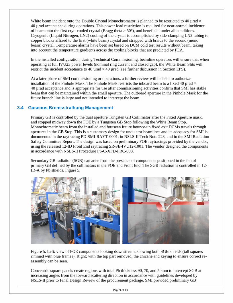
Secondary GB radiation (SGB) can arise from the presence of components positioned in the fan of primary GB defined by the collimators in the FOE and Front End. The SGB radiation is controlled in 12-ID-A by Pb shields, Figure 5.
Figure 5. Left: view of FOE components looking downstream, showing both SGB shields (tall squares rimmed with blue frames). Right: with the top part removed, the chicane and keying to ensure correct re-assembly can be seen.
Concentric square panels create regions with total Pb thickness 90, 70, and 50mm to intercept SGB at increasing angles from the forward scattering direction in accordance with guidelines developed by NSLS-II prior to Final Design Review of the procurement package. SMI provided preliminary GB
Page 10 of 13
analysis using FLUKA (Tech Note 147) prior to fabrication to confirm the adequacy of the design. The as-built configuration, utilizing Survey data as documented in the installation travelers, was used for the shielding analysis model for the final confirmation of the configuration (Tech Note 228).
3.5 Configuration Control
All radiation safety components are under configuration control, in accordance with the NSLS-II Radiation Safety Component Configuration Management procedure PS-C- XFD-PRC-058.
3.6 Area Radiation Monitors
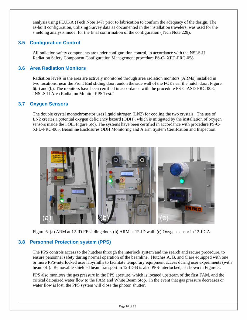
Radiation levels in the area are actively monitored through area radiation monitors (ARMs) installed in two locations: near the Front End sliding door, andon the side wall of the FOE near the hutch door, Figure 6(a) and (b). The monitors have been certified in accordance with the procedure PS-C-ASD-PRC-008, “NSLS-II Area Radiaiton Monitor PPS Test.”
3.7 Oxygen Sensors
The double crystal monochromator uses liquid nitrogen (LN2) for cooling the two crystals. The use of LN2 creates a potential oxygen deficiency hazard (ODH), which is mitigated by the installation of oxygen sensors inside the FOE, Figure 6(c). The systems have been certified in accordance with procedure PS-C-XFD-PRC-005, Beamline Enclosures ODH Monitoring and Alarm System Certifcation and Inspection.
Figure 6. (a) ARM at 12-ID FE sliding door. (b) ARM at 12-ID wall. (c) Oxygen sensor in 12-ID-A.
3.8 Personnel Protection system (PPS)
The PPS controls access to the hutches through the interlock system and the search and secure procedure, to ensure personnel safety during normal operation of the beamline. Hutches A, B, and C are equipped with one or more PPS-interlocked user labyrinths to facilitate temporary equipment access during user experiments (with beam off). Removable shielded beam transport in 12-ID-B is also PPS-interlocked, as shown in Figure 3.
PPS also monitors the gas pressure in the PPS aperture, which is located upstream of the first FAM, and the critical deionized water flow to the FAM and White Beam Stop. In the event that gas pressure decreases or water flow is lost, the PPS system will close the photon shutter.
Page 11 of 13
4 4 INSTRUMENT READINESS 4.1 Survey and alignment
The beamline components are installed according to the specifications and the respective final designs. Installation of the components is verified by the NSLS-II Survey Group working closely with the beamline staff and documented on the travelers.
4.2 Utilities
The following services/capabilities are deployed at the beamline:
• Electrical power distribution to all electrical power outlets, light fixtures, fans, etc., in the hutches and along the beamline
• Distribution of deionized water to the FOE for high heat load components
• Distribution of process chilled water to 12-ID-B and -C for experimental purposes including water cooled turbo pumps at the WAXS and SAXS chambers, and all water-cooled racks
• LN2 distribution to the LN2 cryocooler on the mezzanine
• Compressed air
• Dry nitrogen gas
• Network connectivity
• Cabling and piping support for all utilities, including EPS and PPS
4.3 Vacuum System and Pressure Safety
SMI is a windowless beamline in its operating configuration. The first two SMI vacuum sections at the ratchet wall, upstream and downstream of the FAM, are specified and operating at vacuum pressures of 4×10⁻⁹ torr or better. The vacuum pressure for FOE optical components is specified to be 10-8 torr or better. There is no physical barrier between the beamline vacuum and Front End vacuum. Ion pumps installed upstream and downstream of the FAM provide differential pumping, and the effectiveness of this scheme has been confirmed using calculations that show maintenance of a factor of four or more in pressure differential. Ion pumps through the length of the beamline from the Photon Delivery sections, through the 12-ID-B/C beam transport to the CRL Transfocator in 12-ID-C maintain local pressures that may rise into the 1×10⁻⁷ torr range downstream.
4.3.1 Common Branch Vacuum Sections The common branch vacuum sections in 12-ID-A comprise white beam optical components (FAM to WB Stop) and mono beam components (GB Stop, mirrors, diagnostics, photon shutter). Vacuum vessels containing water or LN2 coolant are equipped with burst disks. A fast valve sensor located at the GB Stop is monitored by the Front End and in case of fault triggers the Front End fast valve and shutters to close. An RGA is installed in the first vacuum section for continuous monitoring. A second RGA is installed at the Vertical Focusing Mirror for diagnostic purposes and is not connected during regular operations.
4.3.2 Inboard Branch Beam Transport Vacuum Sections The inboard branch vacuum sections begin with the beam pipe exiting the vertical mirrors vessel. (A port for the outboard branch connection is closed with a blank flange.) A fast valve is connected just downstream of the vertical mirrors vessel to protect mirrors and upstream optics from vacuum faults downstream. After exiting the FOE, fixed shielded transport pipe leads through the walkway and into the optics closet, hutch 12-ID-B-1. Beam transport further leads through components and exits 12-ID-B-1 and terminates at a shielded pipe enclosure in 12-ID-B (see Figure 3). Inside 12-ID-B-1 is a vacuum gauge cross containing a fast valve sensor. This sensor will detect faults in the case of a breach of the Be window for operation with beam in 12-ID-B and close the FOE fast valve.

Page 12 of 13
4.3.3 GISAXS/WAXS Experiment Vacuum Sections For operation with the GISAXS/WAXS equipment in 12-ID-C, the removable shielded beam pipe (Figure 3) conducts beam to the CRL Transfocator and WAXS chamber. These assemblies are shown in Figure 7. The WAXS chamber terminates the equipment in IRR scope. SMI Work Instruction NSLSII-12ID-WIN-003, “WAXS Chamber Venting,” gives the procedure for venting and pump-down of the WAXS chamber to insert and measure samples. Within the chamber are installed several pieces of vacuum rated instrumentation, including the water-cooled Pilatus 300K-W detector. The 300K-W water hoses are separated from the beamline vacuum by bellows installed inside the chamber and creating a barrier between the vacuum and the water feedthroughs. A fast valve sensor is installed on the WAXS chamber gauge cross along with a burst disk. The fast valve sensor will detect faults in the WAXS chamber and close the FOE fast valve. The WAXS chamber is pumped by an EPX turbo pump with water cooling. Water leak detection has been installed in the hutch.
Figure 7. CRL Transfocator (at right, background) and WAXS sample vacuum chamber (left, foreground).
4.4 Controls
All motorized components have been tested by the Controls Group and documented in the travelers. Controls System Studio (CSS) screens have been prepared to access the motors on the components. The individual motors are also accessible using standard EPICS Extensible Display Manager (EDM) screens.
4.5 Equipment Protection System (EPS)
The EPS at the SMI beamline performs the following functions:
• Vacuum pressure monitoring and interlock for all vacuum sections
• Temperature monitoring and interlock for all non-safety-related components, including those exposed to heat load in the monochromator, and in-vacuum motors
• Water flow monitoring for non-PPS high heat load components
• Control of WAXS turbo pump water solenoid valves and monitor of water leak detection system
• Monitoring of the 12-ID-A and 12-ID-B fast valve sensors / FOE fast valve operation, with logic to close other gate valves and beam shutter in case of fault
Page 13 of 13
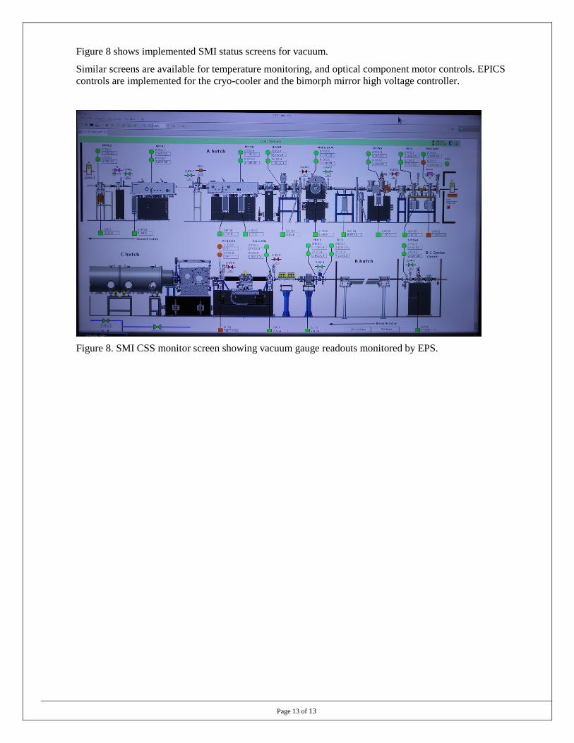
Figure 8 shows implemented SMI status screens for vacuum.
Similar screens are available for temperature monitoring, and optical component motor controls. EPICS controls are implemented for the cryo-cooler and the bimorph mirror high voltage controller.
Figure 8. SMI CSS monitor screen showing vacuum gauge readouts monitored by EPS.