Embed Size (px)
Citation preview
web: www.farmet.cz e-mail: [email protected]
IČ: 46504931 DIČ: CZ46504931
Farmet a. s. Jiřinková 276 552 03 Česká Skalice, CZ
telefon: +420 491 450 111 fax: +420 491 450 136 GSM: +420 774 715 738
OPERATING MANUAL
SOFTER 12,5 PS
Edition: 5 | effective from: 8. 10. 2020
Manual
SOFTER 12,5 PS
2 │ 54
Dear Customer, The SOFTER semi-mounted disc plough-harrows are quality products of Farmet a.s. Ceska Skalice. You can fully utilise the advantages of your machine after thoroughly studying the operating manual. The serial number of the machine is punched on the production label and written in the operating manual
(see Table 1). This machine serial number must be stated whenever ordering spare parts for possible repairs. The production label is located on the middle frame near the tow bar.
Use only spare parts for these machines according to the Spare parts catalogue officially issued by the manufacturer, Farmet a.s. Ceska Skalice. Possibilities of Use of the Disc Plough-harrow
The SOFTER disc plough-harrow is intended for ploughing all types of soil up to the depth of 12cm (4.7 in).
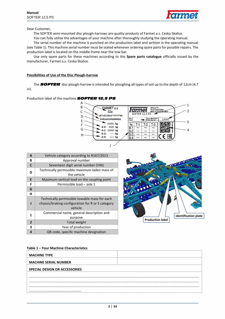
Production label of the machine SOFTER 12,5 PS
Table 1 – Your Machine Characteristics
MACHINE TYPE
MACHINE SERIAL NUMBER
SPECIAL DESIGN OR ACCESSORIES
..................................................................................................................................................................................
..................................................................................................................................................................................
..................................................................................................................................................................................
.....................……………………………….
A Vehicle category according to R167/2013
B Approval number
C Seventeen digit serial number (VIN)
D Technically permissible maximum laden mass of
the vehicle
E Maximum vertical load on the coupling point
F Permissible load – axle 1
G
H
J
Technically permissible towable mass for each chassis/braking configuration for R or S category
vehicle
1 Commercial name, general description and
purpose
2 Total weight
3 Year of production
4 QR code, specific machine designation
SOFTER 12,5 PS
10000
10000
3000
13000
A B C
D E F
1
2
3
4
J
G
H
Identification plate Production label
Manual
SOFTER 12,5 PS
3 │ 54
TABLE OF CONTENTS
MACHINE LIMIT PARAMETERS ................................................................................................................................ 5 Technical parameters ......................................................................................................................................... 5 Safety statement ................................................................................................................................................ 5
A. GENERAL INSTRUCTIONS FOR USE ................................................................................................................. 6 Protective tools .................................................................................................................................................. 6
B. MACHINE TRANSPORT USING TRANSPORT MEANS ....................................................................................... 7 C. MACHINE HANDLING USING LIFTING EQUIPMENT ........................................................................................ 8 D. WORK SAFETY LABELS .................................................................................................................................... 9 1. DESCRIPTION ................................................................................................................................................ 13
1.1. Working parts of the machine ............................................................................................................. 13 1.2. Hydraulic valve function ...................................................................................................................... 14 1.3. Hydraulic diagram of the machine ...................................................................................................... 17 1.4. Brake distribution of the machine ....................................................................................................... 18 1.5. Lighting equipment .............................................................................................................................. 21 1.6. Hydraulic frame lock ............................................................................................................................ 22 1.7. Transport rests on the axle .................................................................................................................. 22 1.8. Device against unauthorized use ......................................................................................................... 23 1.9. Tool set ................................................................................................................................................ 23
2. MACHINE ASSEMBLY AT THE CUSTOMER .................................................................................................... 24 3. COMMISSIONING ......................................................................................................................................... 24
3.1 Agregation to a tractor ........................................................................................................................ 25 3.2 Hydraulics connection ......................................................................................................................... 26 3.3 Machine folding and unfolding ............................................................................................................ 28
4. MACHINE TRANSPORT ON ROADS ............................................................................................................... 32 5. MACHINE ADJUSTMENT ............................................................................................................................... 33
5.1 Machine working depth adjtustment .................................................................................................. 33 5.2 Washers on the drawbar ..................................................................................................................... 34 5.3 Setting the front equipment ................................................................................................................ 34 5.4 Setting side deflectors ......................................................................................................................... 35 5.5 Setting edge discs ................................................................................................................................ 35 5.6 Setting shut-off valve ........................................................................................................................... 36 5.7 Setting the rear flexible leveller .......................................................................................................... 37 5.8 Setting the cutting disc ........................................................................................................................ 38 5.9 Turning at headland............................................................................................................................. 38
6. ELECTRONIC HYDRAULIC CIRCUIT SWITCH ................................................................................................... 39 6.1 Description of the equipment ............................................................................................................. 39 6.2 System wiring diagram ........................................................................................................................ 39 6.2.1 Designation of system components .................................................................................................... 39 6.2.2 Wiring diagram .................................................................................................................................... 40 6.3 Main components ................................................................................................................................ 41 6.3.1 Controller ............................................................................................................................................. 41 6.3.2 Hydraulic block .................................................................................................................................... 41 6.3.3 Power supply ....................................................................................................................................... 42 6.4 Functions + pictograms........................................................................................................................ 42 6.5 Connecting procedure ......................................................................................................................... 43 6.6 Emergency state .................................................................................................................................. 43
7. ADJUSTMENT AND MAINTENANCE PROCEDURES ....................................................................................... 44 7.1. Setting the hose mount ....................................................................................................................... 44 7.2. Depth connecting rods for the front row ............................................................................................ 44 7.3. Tracing wheel position......................................................................................................................... 45 7.4. Roller positions .................................................................................................................................... 45 7.5. Air jet drainage .................................................................................................................................... 46
8. MACHINE MAINTENANCE AND REPAIRS ...................................................................................................... 47 8.1. Maintenance plan ......................................................................................................................................... 48 9. MACHINE STORAGE ...................................................................................................................................... 51 10. MACHINE LUBRICATION SCHEDULE ............................................................................................................. 51 11. ENVIRONMENTAL PROTECTION ................................................................................................................... 52 12. MACHINE DISPOSAL AFTER SERVICE LIFE EXPIRY ......................................................................................... 52
Manual
SOFTER 12,5 PS
4 │ 54
13. SERVICING AND WARANTY CONDITIONS ..................................................................................................... 52 13.1. Servicing .............................................................................................................................................. 52 13.2. WARRANTY .......................................................................................................................................... 52
CE Certificate of Conformity ....................................................................................................................... 53
GB
Manual
SOFTER 12,5 PS
5 │ 54
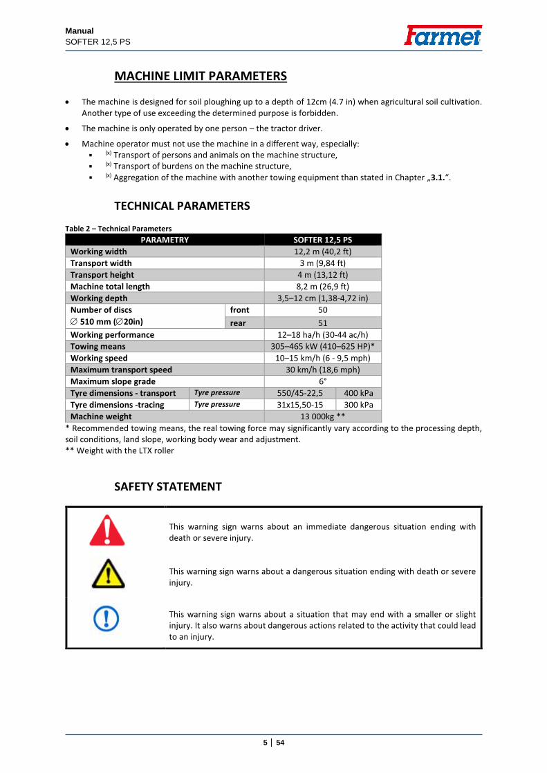
MACHINE LIMIT PARAMETERS
The machine is designed for soil ploughing up to a depth of 12cm (4.7 in) when agricultural soil cultivation. Another type of use exceeding the determined purpose is forbidden.
The machine is only operated by one person – the tractor driver.
Machine operator must not use the machine in a different way, especially: (x) Transport of persons and animals on the machine structure, (x) Transport of burdens on the machine structure, (x) Aggregation of the machine with another towing equipment than stated in Chapter „3.1.“.
TECHNICAL PARAMETERS Table 2 – Technical Parameters
PARAMETRY SOFTER 12,5 PS
Working width 12,2 m (40,2 ft)
Transport width 3 m (9,84 ft)
Transport height 4 m (13,12 ft)
Machine total length 8,2 m (26,9 ft)
Working depth 3,5–12 cm (1,38-4,72 in)
Number of discs
510 mm (20in)
front 50
rear 51
Working performance 12–18 ha/h (30-44 ac/h)
Towing means 305–465 kW (410–625 HP)*
Working speed 10–15 km/h (6 - 9,5 mph)
Maximum transport speed 30 km/h (18,6 mph)
Maximum slope grade 6°
Tyre dimensions - transport Tyre pressure 550/45-22,5 400 kPa
Tyre dimensions -tracing Tyre pressure 31x15,50-15 300 kPa
Machine weight 13 000kg **
* Recommended towing means, the real towing force may significantly vary according to the processing depth, soil conditions, land slope, working body wear and adjustment. ** Weight with the LTX roller
SAFETY STATEMENT
This warning sign warns about an immediate dangerous situation ending with death or severe injury.
This warning sign warns about a dangerous situation ending with death or severe injury.
This warning sign warns about a situation that may end with a smaller or slight injury. It also warns about dangerous actions related to the activity that could lead to an injury.
Manual
SOFTER 12,5 PS
6 │ 54
A. GENERAL INSTRUCTIONS FOR USE The machine is made in accordance with the latest equipment state and approved safety regulations.
However, dangers of user or third person injury or machine damage or creation of other material damage may arise during use.
Use the machine only in a technically sound condition, in accordance with its purpose, aware of possible dangers, and while adhering to the safety instructions of this operating manual! The manufacturer is not liable for damages caused by the use of the machine that is in contradiction with the limit parameters of the machine (p. 4) and with the instructions for the use of the machine (Chapter A and 3). The user bears the risk.
Immediately remove especially the failures that may negatively affect safety!
Machine operation may be performed by a person authorised by the operator under these conditions:
It must own a valid driver's licence of the corresponding category,
It must be demonstrably familiarised with the safety regulations for work with the machine and must practically master the machine operation,
The machine may not be operated by juveniles,
It must know the meaning of the safety signs located on the machine. Their respecting is important for safe and reliable machine operation.
Maintenance and servicing repairs on the machine may only be performed by a person:
Authorised by the operator,
Educated in the machinery field with knowledge of repairs of similar machines,
Demonstrably familiarised with safety regulations for work with the machine,
During a repair of a machine connected to a tractor, it must own a driver's licence of the corresponding category.
Machine operator must secure the safety of other persons when working with the machine or transporting the machine.
During machine work in the field or during transport, the operator must control the machine from the tractor's cabin.
The operator may enter the machine structure only with the machine at rest and blocked against movement, namely only for these reasons:
Adjustment of the machine working parts,
Repair and maintenance of the machine,
Release and securing of spherical valves of the axle,
Securing of spherical valves of the axle before folding the side frames,
Adjustment of the working parts of the machine after unfolding the side frames.
When climbing on the machine, do not step on the axle tyres, rollers, discs or other revolving parts. Those may turn and you can cause very serious injuries by the subsequent fall.
Any changes or modifications of machine may be performed only with written consent of the manufacturer. For possible damage arisen due to ignoring this instruction, the producer bears no responsibility. The machine must be maintained equipped with prescribed accessories and equipment including safety marking. All warning and safety signs must be legible and in their places. In case of damage or loss, these signs must be immediately renewed.
The operator must have the Operating Manual with the work safety requirements available at any time when working with the machine.
The operator must not consume alcohol, medicines, narcotic and hallucinogenic substances that decrease his attention and coordination capabilities while using the machine. If the operator must use medicines prescribed by a physician or uses freely sold medicines, he must be informed by a physician, whether he is capable of responsible and safe operation of the machine under these circumstances.
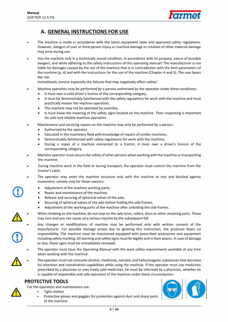
PROTECTIVE TOOLS For the operation and maintenance use:
Tight clothes Protective gloves and goggles for protection against dust and sharp parts
of the machine
Manual
SOFTER 12,5 PS
7 │ 54
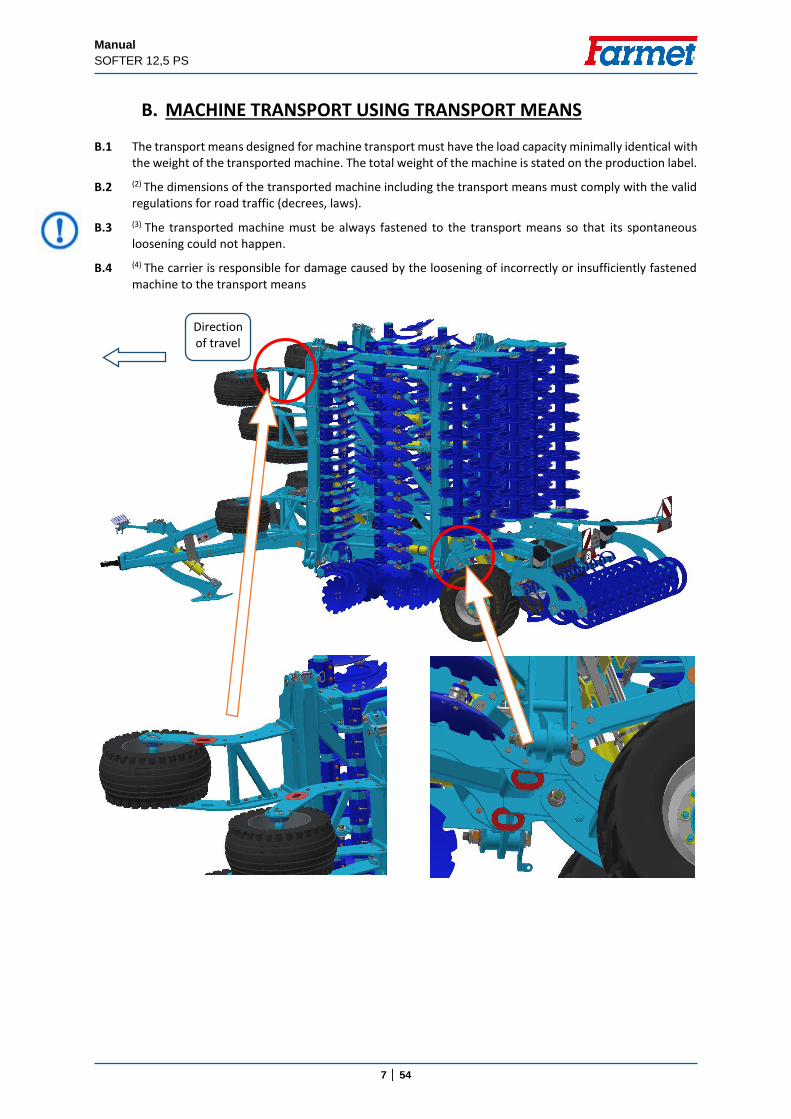
B. MACHINE TRANSPORT USING TRANSPORT MEANS B.1 The transport means designed for machine transport must have the load capacity minimally identical with
the weight of the transported machine. The total weight of the machine is stated on the production label.
B.2 (2) The dimensions of the transported machine including the transport means must comply with the valid regulations for road traffic (decrees, laws).
B.3 (3) The transported machine must be always fastened to the transport means so that its spontaneous loosening could not happen.
B.4 (4) The carrier is responsible for damage caused by the loosening of incorrectly or insufficiently fastened machine to the transport means
Direction of travel
Manual
SOFTER 12,5 PS
8 │ 54
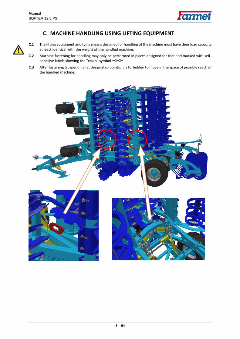
C. MACHINE HANDLING USING LIFTING EQUIPMENT C.1 The lifting equipment and tying means designed for handling of the machine must have their load capacity
at least identical with the weight of the handled machine.
C.2 Machine fastening for handling may only be performed in places designed for that and marked with self-adhesive labels showing the "chain" symbol
C.3 After fastening (suspending) at designated points, it is forbidden to move in the space of possible reach of the handled machine.
Manual
SOFTER 12,5 PS
9 │ 54
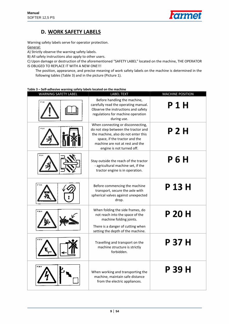
D. WORK SAFETY LABELS Warning safety labels serve for operator protection. General: A) Strictly observe the warning safety labels. B) All safety instructions also apply to other users. C) Upon damage or destruction of the aforementioned "SAFETY LABEL" located on the machine, THE OPERATOR IS OBLIGED TO REPLACE IT WITH A NEW ONE!!! The position, appearance, and precise meaning of work safety labels on the machine is determined in the
following tables (Table 3) and in the picture (Picture 1).
Table 3 – Self-adhesive warning safety labels located on the machine
WARNING SAFETY LABEL LABEL TEXT MACHINE POSITION
Before handling the machine, carefully read the operating manual. Observe the instructions and safety regulations for machine operation
during use.
P 1 H
When connecting or disconnecting,
do not step between the tractor and the machine, also do not enter this
space, if the tractor and the machine are not at rest and the
engine is not turned off.
P 2 H
Stay outside the reach of the tractor - agricultural machine set, if the tractor engine is in operation.
P 6 H
Before commencing the machine
transport, secure the axle with spherical valves against unexpected
drop.
P 13 H
When folding the side frames, do not reach into the space of the
machine folding joints.
There is a danger of cutting when setting the depth of the machine.
P 20 H
Travelling and transport on the
machine structure is strictly forbidden.
P 37 H
When working and transporting the machine, maintain safe distance
from the electric appliances.
P 39 H
Manual
SOFTER 12,5 PS
10 │ 54
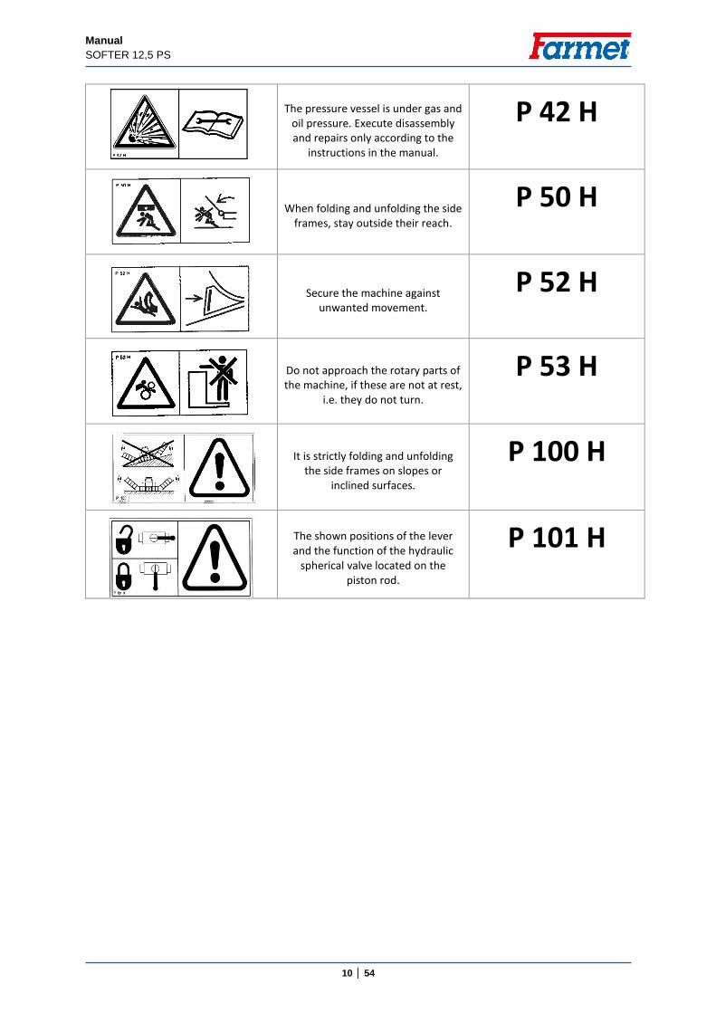
The pressure vessel is under gas and
oil pressure. Execute disassembly and repairs only according to the
instructions in the manual.
P 42 H
When folding and unfolding the side frames, stay outside their reach.
P 50 H
Secure the machine against unwanted movement.
P 52 H
Do not approach the rotary parts of the machine, if these are not at rest,
i.e. they do not turn.
P 53 H
It is strictly folding and unfolding the side frames on slopes or
inclined surfaces.
P 100 H
The shown positions of the lever and the function of the hydraulic
spherical valve located on the piston rod.
P 101 H
Manual
SOFTER 12,5 PS
11 │ 54
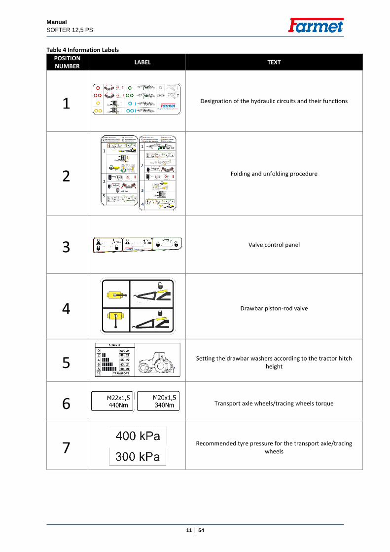
Table 4 Information Labels
POSITION NUMBER
LABEL TEXT
1
Designation of the hydraulic circuits and their functions
2
Folding and unfolding procedure
3
Valve control panel
4
Drawbar piston-rod valve
5
Setting the drawbar washers according to the tractor hitch
height
6
Transport axle wheels/tracing wheels torque
7
Recommended tyre pressure for the transport axle/tracing wheels
Manual
SOFTER 12,5 PS
12 │ 54
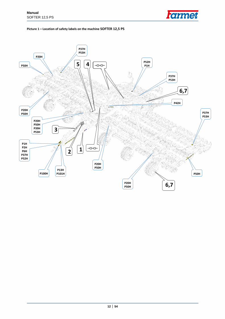
Picture 1 – Location of safety labels on the machine SOFTER 12,5 PS
P1H P2H P6H
P37H P52H
P13H P101H P100H
P20H P50H
P20H P50H P39H P53H
P37H P53H
P20H P50H
P50H
P52H P1H
P37H P53H
P37H P53H
P42H
P20H P50H
P50H
P20H
3
2 1
5 4
6,7
6,7
Manual
SOFTER 12,5 PS
13 │ 54
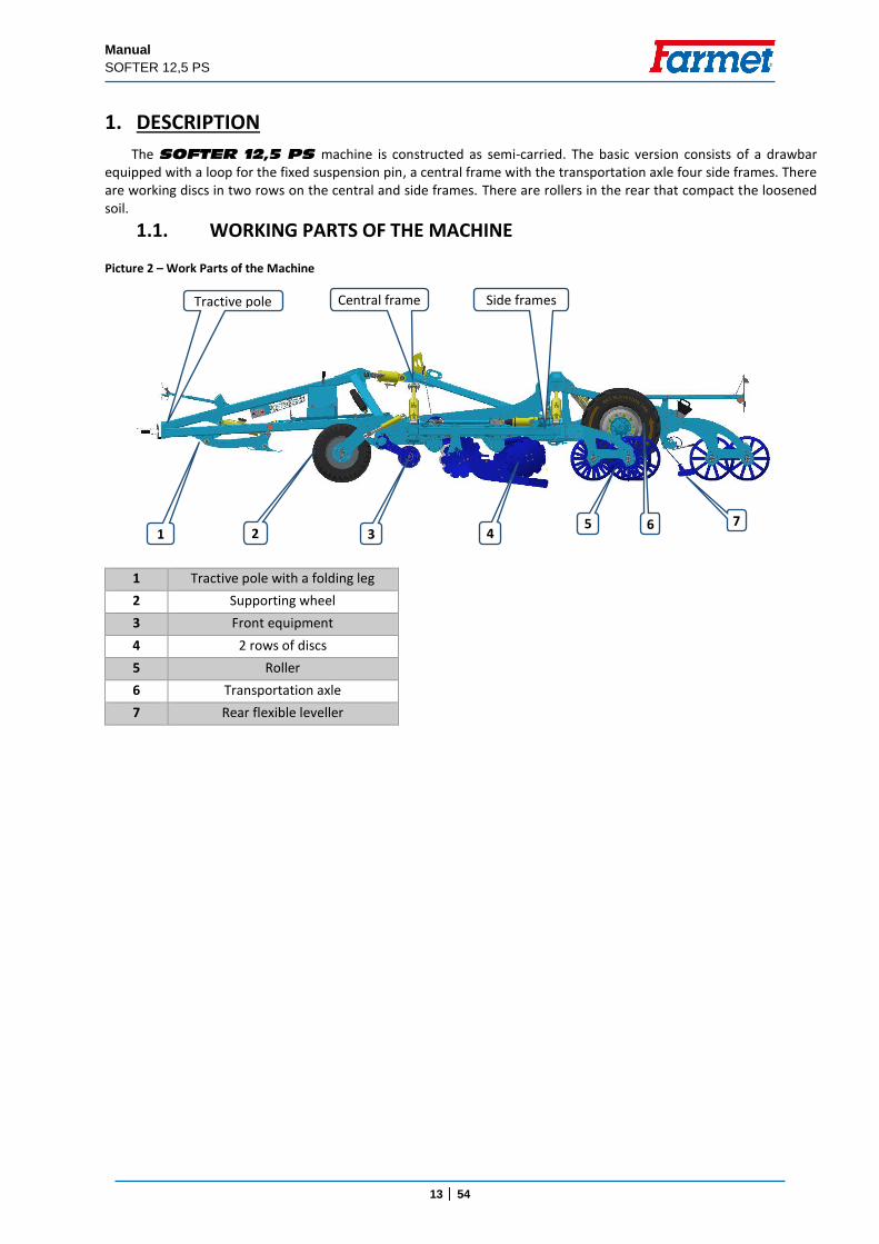
1. DESCRIPTION
The SOFTER 12,5 PS machine is constructed as semi-carried. The basic version consists of a drawbar equipped with a loop for the fixed suspension pin, a central frame with the transportation axle four side frames. There are working discs in two rows on the central and side frames. There are rollers in the rear that compact the loosened soil.
1.1. WORKING PARTS OF THE MACHINE
1 Tractive pole with a folding leg
2 Supporting wheel
3 Front equipment
4 2 rows of discs
5 Roller
6 Transportation axle
7 Rear flexible leveller
Picture 2 – Work Parts of the Machine
4
Central frame
Side frames
1 7
Tractive pole
2 5
3 6
Manual
SOFTER 12,5 PS
14 │ 54
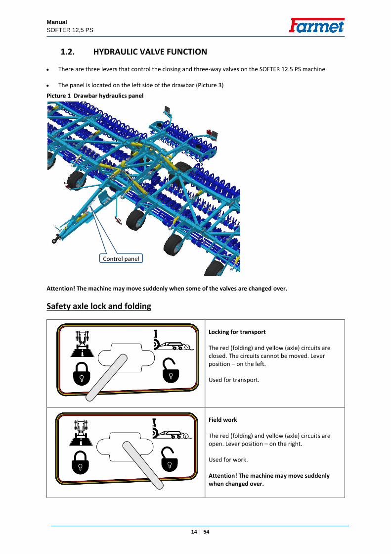
1.2. HYDRAULIC VALVE FUNCTION
There are three levers that control the closing and three-way valves on the SOFTER 12.5 PS machine
The panel is located on the left side of the drawbar (Picture 3)
Attention! The machine may move suddenly when some of the valves are changed over.
Safety axle lock and folding
Locking for transport
The red (folding) and yellow (axle) circuits are closed. The circuits cannot be moved. Lever position – on the left.
Used for transport.
Field work
The red (folding) and yellow (axle) circuits are open. Lever position – on the right.
Used for work.
Attention! The machine may move suddenly when changed over.
Control panel
Picture 1 Drawbar hydraulics panel
Manual
SOFTER 12,5 PS
15 │ 54
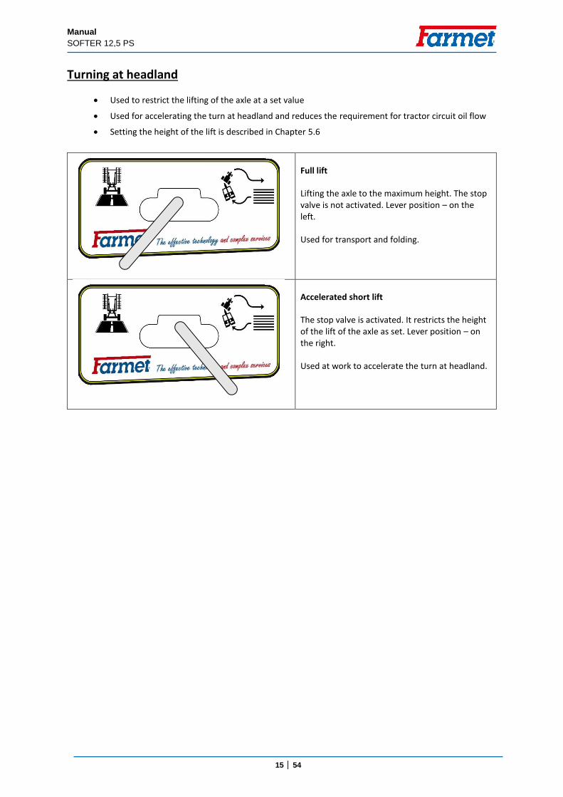
Turning at headland
Used to restrict the lifting of the axle at a set value
Used for accelerating the turn at headland and reduces the requirement for tractor circuit oil flow
Setting the height of the lift is described in Chapter 5.6
Full lift
Lifting the axle to the maximum height. The stop valve is not activated. Lever position – on the left.
Used for transport and folding.
Accelerated short lift
The stop valve is activated. It restricts the height of the lift of the axle as set. Lever position – on the right.
Used at work to accelerate the turn at headland.
Manual
SOFTER 12,5 PS
16 │ 54
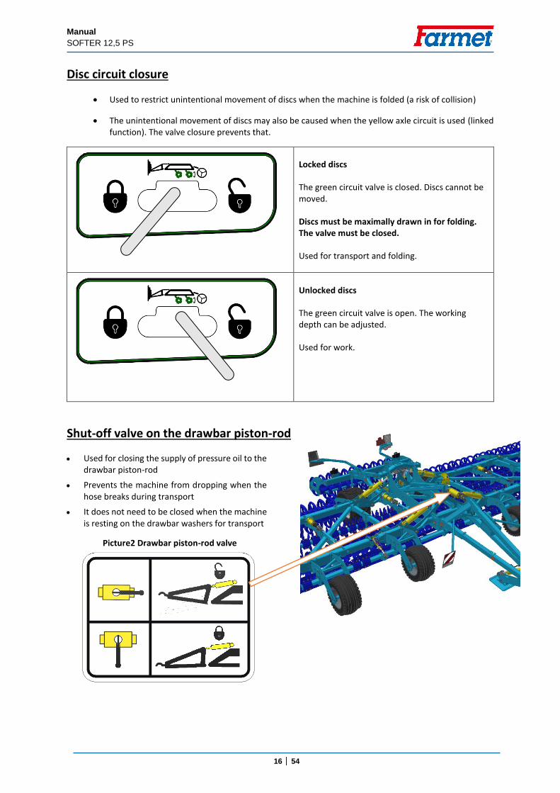
Disc circuit closure
Used to restrict unintentional movement of discs when the machine is folded (a risk of collision)
The unintentional movement of discs may also be caused when the yellow axle circuit is used (linked function). The valve closure prevents that.
Locked discs
The green circuit valve is closed. Discs cannot be moved.
Discs must be maximally drawn in for folding. The valve must be closed.
Used for transport and folding.
Unlocked discs
The green circuit valve is open. The working depth can be adjusted.
Used for work.
Shut-off valve on the drawbar piston-rod
Used for closing the supply of pressure oil to the drawbar piston-rod
Prevents the machine from dropping when the hose breaks during transport
It does not need to be closed when the machine is resting on the drawbar washers for transport
Picture2 Drawbar piston-rod valve
Manual
SOFTER 12,5 PS
17 │ 54
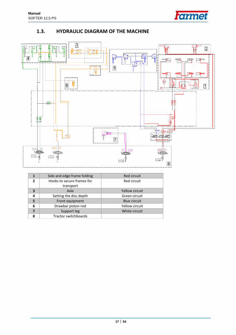
1.3. HYDRAULIC DIAGRAM OF THE MACHINE
1 Side and edge frame folding Red circuit
2 Hooks to secure frames for transport
Red circuit
3 Axle Yellow circuit
4 Setting the disc depth Green circuit
5 Front equipment Blue circuit
6 Drawbar piston-rod Yellow circuit
7 Support leg White circuit
8 Tractor switchboards
Manual
SOFTER 12,5 PS
18 │ 54
1.4. BRAKE DISTRIBUTION OF THE MACHINE
The standard version of the machine includes a single-circuit two-line braking system by KNORR BREMSE
Braking is provided by spring brake cylinders – the parking brake is implemented inside and it is automatic (controlled by a button, see below).
To release the parking brake, a sufficient air pressure in the system is required. Always check that the parking brake is released before driving.
If the machine is equipped with brakes, they must be connected to the tractor when driving.
Always release the brakes of the machine when lifting the machine on the axle.
ATTENTION !!! The parking brake is activated automatically when there is a leak of air from the system and physical brake release is only possible mechanically, see below.
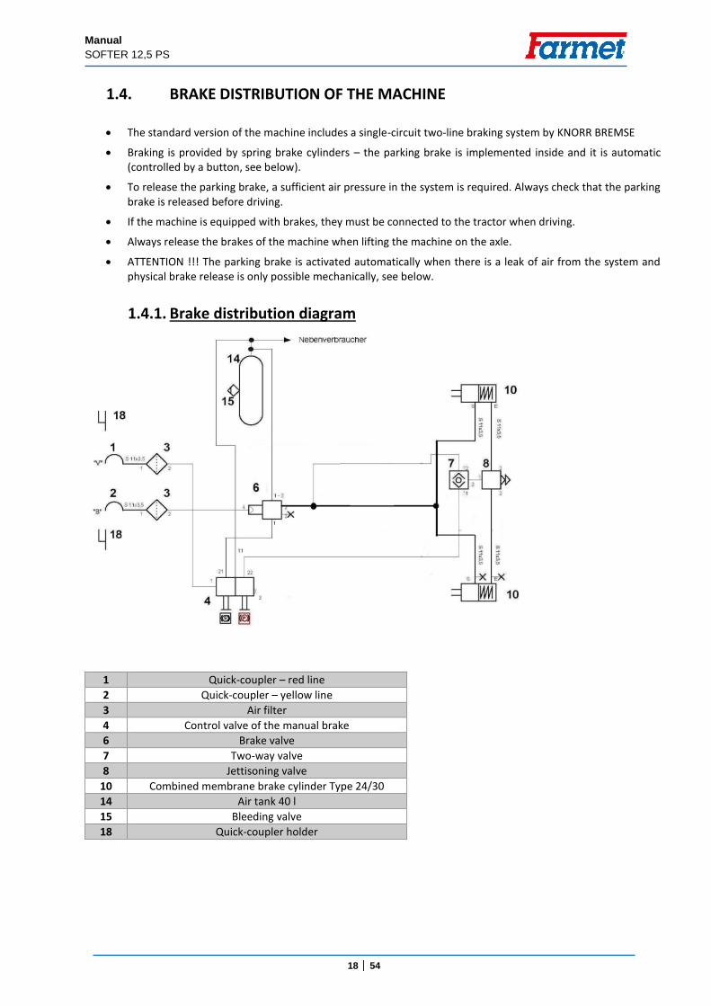
1.4.1. Brake distribution diagram
1 Quick-coupler – red line
2 Quick-coupler – yellow line
3 Air filter
4 Control valve of the manual brake
6 Brake valve
7 Two-way valve
8 Jettisoning valve
10 Combined membrane brake cylinder Type 24/30
14 Air tank 40 l
15 Bleeding valve
18 Quick-coupler holder
Manual
SOFTER 12,5 PS
19 │ 54
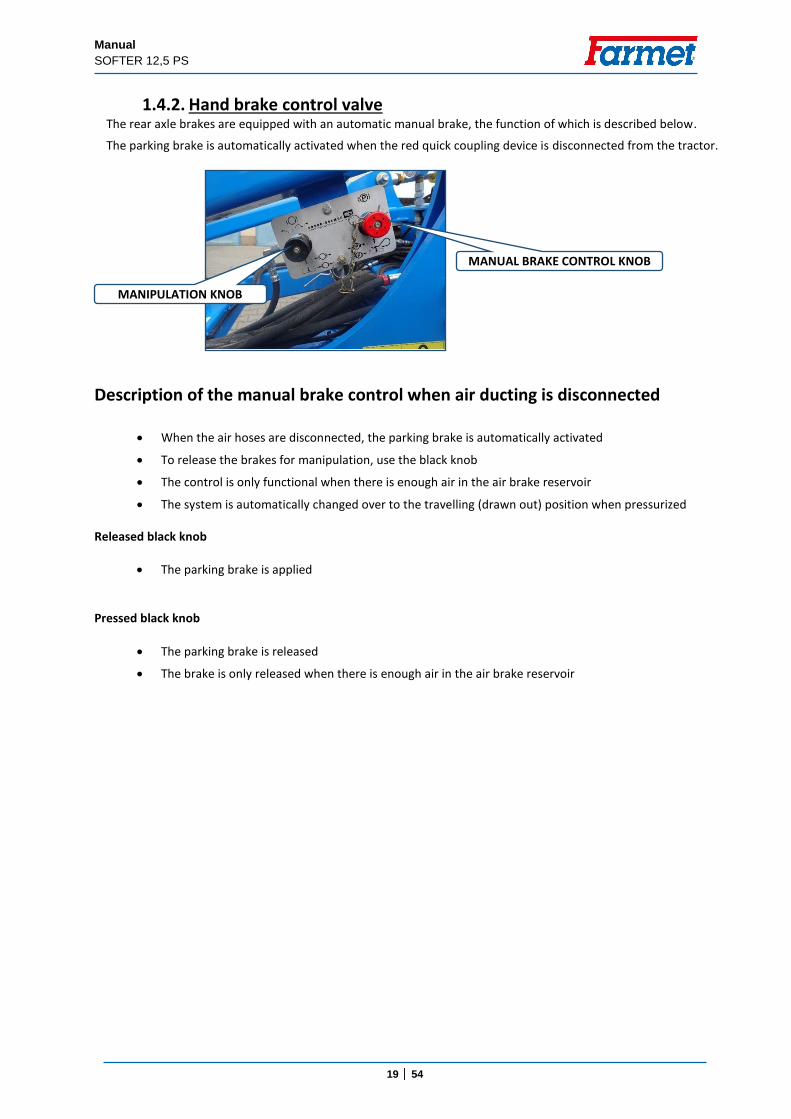
1.4.2. Hand brake control valve The rear axle brakes are equipped with an automatic manual brake, the function of which is described below.
The parking brake is automatically activated when the red quick coupling device is disconnected from the tractor.
Description of the manual brake control when air ducting is disconnected
When the air hoses are disconnected, the parking brake is automatically activated
To release the brakes for manipulation, use the black knob
The control is only functional when there is enough air in the air brake reservoir
The system is automatically changed over to the travelling (drawn out) position when pressurized
Released black knob
The parking brake is applied
Pressed black knob
The parking brake is released
The brake is only released when there is enough air in the air brake reservoir
MANUAL BRAKE CONTROL KNOB
MANIPULATION KNOB
Manual
SOFTER 12,5 PS
20 │ 54
Description of the manual brake control when air ducting is connected The knob has to be pressed when travelling (there is no automatic change over).
It does not need to be used when the machine is disconnected, the brake is automatically activated when the red quick coupling device of the tractor is disconnected.
1.4.3. Emergency brake release in case of air leak
It is possible to release the brakes of the machine using special brake release bolts in case of a leak of air from the brake system.
The bolts are included in the installation unit of the brake cylinder.
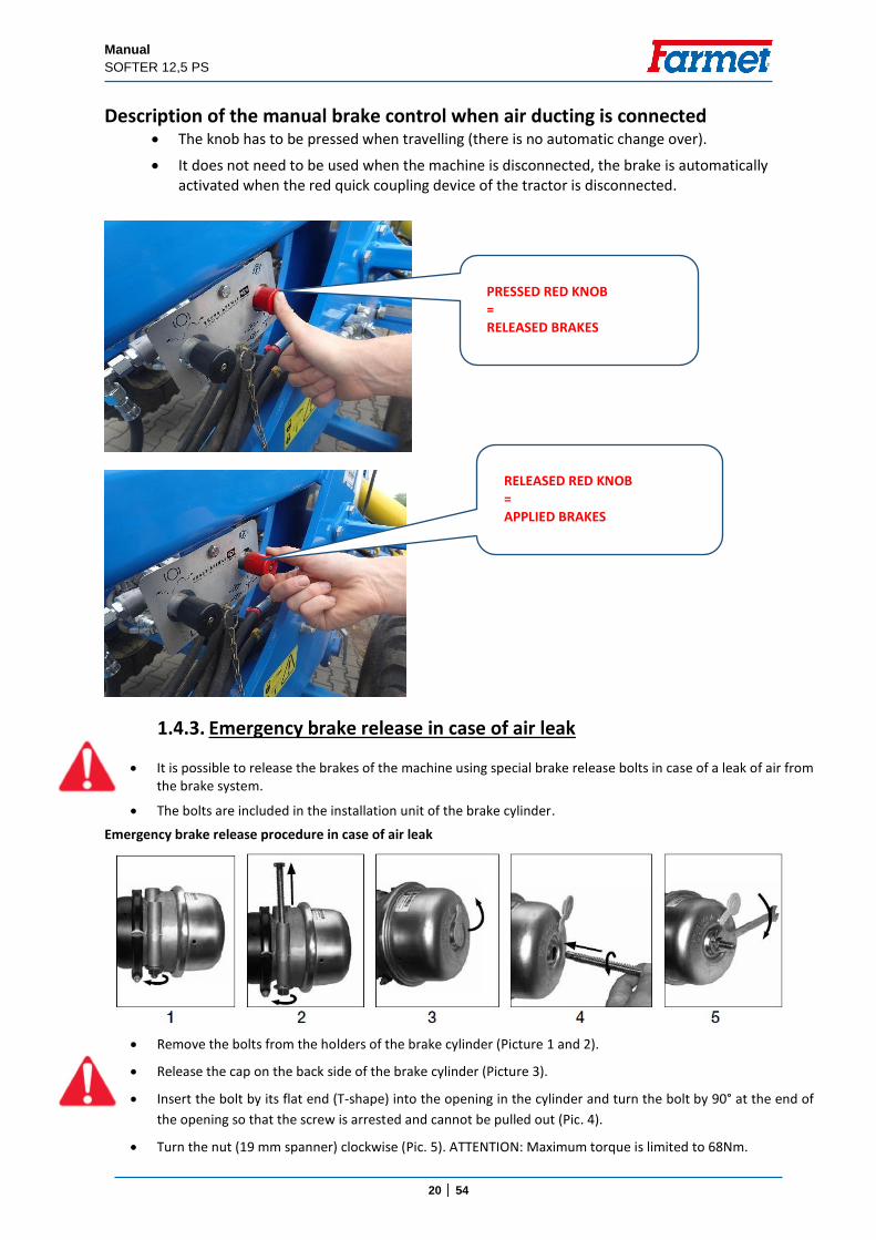
Emergency brake release procedure in case of air leak
Remove the bolts from the holders of the brake cylinder (Picture 1 and 2).
Release the cap on the back side of the brake cylinder (Picture 3).
Insert the bolt by its flat end (T-shape) into the opening in the cylinder and turn the bolt by 90° at the end of
the opening so that the screw is arrested and cannot be pulled out (Pic. 4).
Turn the nut (19 mm spanner) clockwise (Pic. 5). ATTENTION: Maximum torque is limited to 68Nm.
PRESSED RED KNOB = RELEASED BRAKES
RELEASED RED KNOB = APPLIED BRAKES
Manual
SOFTER 12,5 PS
21 │ 54
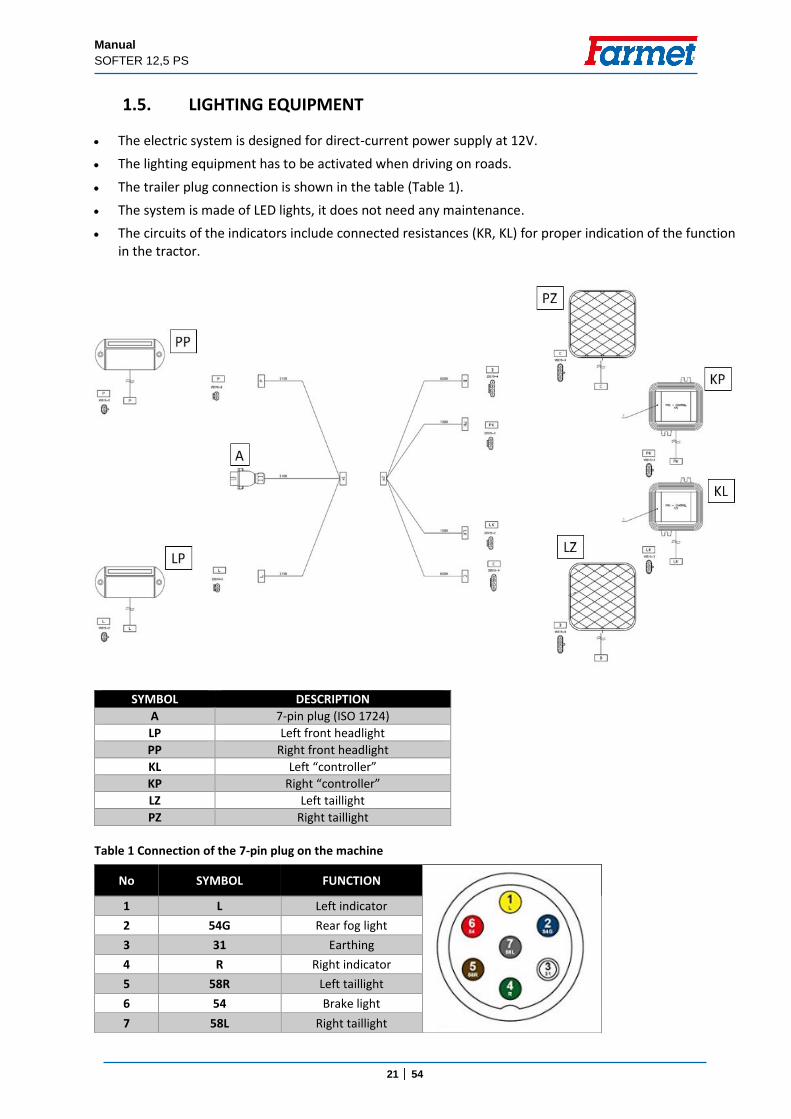
1.5. LIGHTING EQUIPMENT
The electric system is designed for direct-current power supply at 12V.
The lighting equipment has to be activated when driving on roads.
The trailer plug connection is shown in the table (Table 1).
The system is made of LED lights, it does not need any maintenance.
The circuits of the indicators include connected resistances (KR, KL) for proper indication of the function in the tractor.
SYMBOL DESCRIPTION
A 7-pin plug (ISO 1724)
LP Left front headlight
PP Right front headlight
KL Left “controller”
KP Right “controller”
LZ Left taillight
PZ Right taillight
Table 1 Connection of the 7-pin plug on the machine
No SYMBOL FUNCTION
1 L Left indicator
2 54G Rear fog light
3 31 Earthing
4 R Right indicator
5 58R Left taillight
6 54 Brake light
7 58L Right taillight
Manual
SOFTER 12,5 PS
22 │ 54
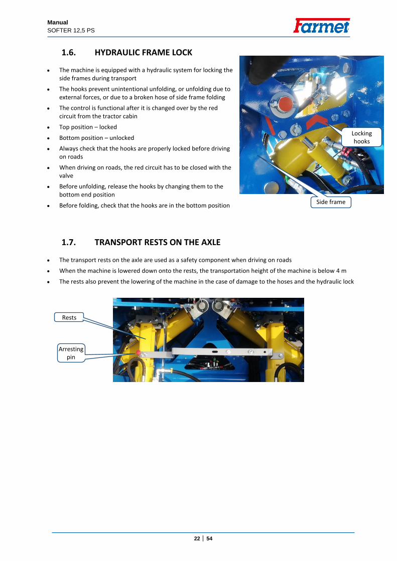
1.6. HYDRAULIC FRAME LOCK
The machine is equipped with a hydraulic system for locking the side frames during transport
The hooks prevent unintentional unfolding, or unfolding due to external forces, or due to a broken hose of side frame folding
The control is functional after it is changed over by the red circuit from the tractor cabin
Top position – locked
Bottom position – unlocked
Always check that the hooks are properly locked before driving on roads
When driving on roads, the red circuit has to be closed with the valve
Before unfolding, release the hooks by changing them to the bottom end position
Before folding, check that the hooks are in the bottom position
1.7. TRANSPORT RESTS ON THE AXLE
The transport rests on the axle are used as a safety component when driving on roads
When the machine is lowered down onto the rests, the transportation height of the machine is below 4 m
The rests also prevent the lowering of the machine in the case of damage to the hoses and the hydraulic lock
Rests
Arresting pin
Locking hooks
Side frame
Manual
SOFTER 12,5 PS
23 │ 54
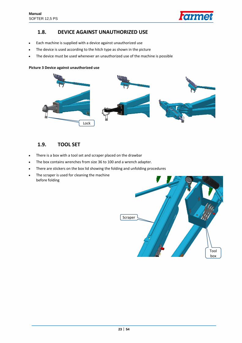
1.8. DEVICE AGAINST UNAUTHORIZED USE
Each machine is supplied with a device against unauthorized use
The device is used according to the hitch type as shown in the picture
The device must be used whenever an unauthorized use of the machine is possible
Picture 3 Device against unauthorized use
1.9. TOOL SET
There is a box with a tool set and scraper placed on the drawbar
The box contains wrenches from size 36 to 100 and a wrench adapter.
There are stickers on the box lid showing the folding and unfolding procedures
The scraper is used for cleaning the machine before folding
Scraper
Tool box
Lock
Manual
SOFTER 12,5 PS
24 │ 54
2. MACHINE ASSEMBLY AT THE CUSTOMER The operator must perform the assembly according to the instructions of the producer, best in cooperation with
the expert servicing technician determined by the producer.
The operator must secure a functional test of all assembled parts after the completion of the machine assembly.
The operator must secure that the handling of the machine using lifting equipment during its assembly is in accordance with chapter „C“.
3. COMMISSIONING
Before taking over the machine, test and check, whether damage occurred during transport and whether all parts contained in the bill of delivery were supplied.
Before commissioning the machine, carefully read this operating manual, especially Chapters A-D p. 6-12. Before the first use of the machine, familiarise yourselves with its controls and overall function.
During work with the machine, observe not only the instructions of this operating manual but also generally valid regulations of work safety, health protection, fire and transport safety, and environmental protection.
The operator must check the machine before every use (commissioning) from the standpoint of completeness, work safety, work hygiene, fire safety, transport safety, and environmental protection.
A machine showing signs of damage must not be commissioned.
Aggregation of the machine with the tractor is to be performed on a flat and hardened surface.
When working on slopes, observe the lowest allowable slope grade of the set TRACTOR - MACHINE.
Before starting the tractor motor, check whether no person or animal is in the working space of the set and push the warning sound signal.
The operator is responsible for the safety and all damage caused by the operation of the tractor and the connected machine.
The operator is obliged to adhere to the technical and safety regulations of the machine determined by the producer when working.
When turning the machine at headland, the Operator must lift the machine, i.e. the working bodies are not in the ground.
The operator is obliged to observe the prescribed working depths and speeds stated in the manual in Tabl. 2/p. 5 when.
The operator is obliged to lower the machine to the ground and secure the set against movement before leaving the tractor cabin.
Manual
SOFTER 12,5 PS
25 │ 54
3.1 AGREGATION TO A TRACTOR
The machine can be connected only to a tractor, whose curb weight is identical or higher than the overall weight of the connected machine.
The machine operator must observe all generally valid regulations of work safety, health protection, fire safety, and environmental protection.
The operator may connect the machine exclusively to a tractor that is equipped with a rear three-point suspension (or bottom fixed suspension) and a functional undamaged hydraulic system.
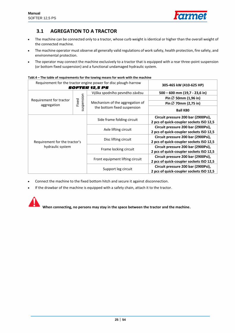
Tabl.4 – The table of requirements for the towing means for work with the machine
Requirement for the tractor engine power for disc plough-harrow SOFTER 12,5 PS
305-465 kW (410-625 HP)
Requirement for tractor aggregation Fi
xed
susp
ensi
on
Výška spodního pevného závěsu 500 – 600 mm (19,7 - 23,6 in)
Mechanism of the aggregation of the bottom fixed suspension
Pin 50mm (1,96 in)
Pin 70mm (2,75 in)
Ball K80
Requirement for the tractor's hydraulic system
Side frame folding circuit Circuit pressure 200 bar (2900Psi),
2 pcs of quick-coupler sockets ISO 12,5
Axle lifting circuit Circuit pressure 200 bar (2900Psi),
2 pcs of quick-coupler sockets ISO 12,5
Disc lifting circuit Circuit pressure 200 bar (2900Psi),
2 pcs of quick-coupler sockets ISO 12,5
Frame locking circuit Circuit pressure 200 bar (2900Psi),
2 pcs of quick-coupler sockets ISO 12,5
Front equipment lifting circuit Circuit pressure 200 bar (2900Psi),
2 pcs of quick-coupler sockets ISO 12,5
Support leg circuit Circuit pressure 200 bar (2900Psi),
2 pcs of quick-coupler sockets ISO 12,5
Connect the machine to the fixed bottom hitch and secure it against disconnection.
If the drawbar of the machine is equipped with a safety chain, attach it to the tractor.
When connecting, no persons may stay in the space between the tractor and the machine.
Manual
SOFTER 12,5 PS
26 │ 54
3.2 HYDRAULICS CONNECTION
Connect the hydraulics only when the hydraulic circuits of the machine and the tractor (aggregate) are in a pressure-less condition.
The hydraulic system is under high pressure. Regularly check for leaks and immediately remove obvious damage of all lines, hoses, and pipe unions.
When seeking and removing leaks, use only the suitable tools.
For connecting the hydraulic system of the machine to the tractor, use the plug (on the machine) and the socket (on the tractor) of the quick-couplers of the same type.
Connect the quick-couplers of the machine to the tractor’s hydraulic circuits so that one hydraulic circuit in the machine is connected to one circuit in the tractor (double-acting hydraulic circuits)
In order to prevent accidental or foreign person (children, passengers) caused movement of the hydraulics, the control switchboards on the tractor must be secured or blocked in the transport position.
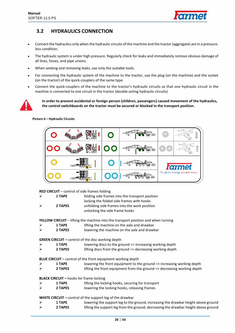
RED CIRCUIT – control of side frames folding 1 TAPE folding side frames into the transport position locking the folded side frames with hooks 2 TAPES unfolding side frames into the work position unlocking the side frame hooks YELLOW CIRCUIT – lifting the machine into the transport position and when turning 1 TAPE lifting the machine on the axle and drawbar 2 TAPES lowering the machine on the axle and drawbar GREEN CIRCUIT – control of the disc working depth 1 TAPE lowering discs to the ground => increasing working depth 2 TAPES lifting discs from the ground => decreasing working depth BLUE CIRCUIT – control of the front equipment working depth 1 TAPE lowering the front equipment to the ground => increasing working depth 2 TAPES lifting the front equipment from the ground => decreasing working depth BLACK CIRCUIT – hooks for frame locking 1 TAPE lifting the locking hooks, securing for transport 2 TAPES lowering the locking hooks, releasing frames WHITE CIRCUIT – control of the support leg of the drawbar 1 TAPE lowering the support leg to the ground, increasing the drawbar height above ground 2 TAPES lifting the support leg from the ground, decreasing the drawbar height above ground
Picture 6 – Hydraulic Circuits
Manual
SOFTER 12,5 PS
27 │ 54
To reduce the number of circuits required in the tractor, it is possible to use an electronic hydraulic circuit switch. Then, it is possible to control up to three machine circuits with one tractor circuit.
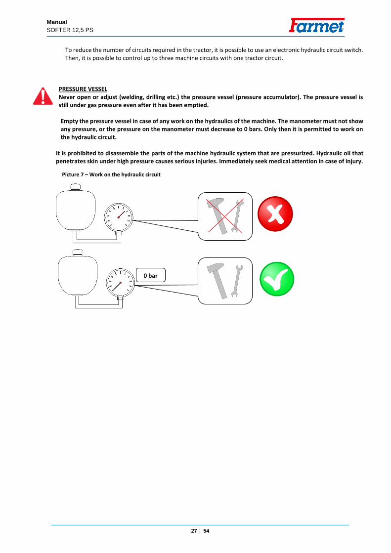
PRESSURE VESSEL Never open or adjust (welding, drilling etc.) the pressure vessel (pressure accumulator). The pressure vessel is still under gas pressure even after it has been emptied. Empty the pressure vessel in case of any work on the hydraulics of the machine. The manometer must not show any pressure, or the pressure on the manometer must decrease to 0 bars. Only then it is permitted to work on the hydraulic circuit.
It is prohibited to disassemble the parts of the machine hydraulic system that are pressurized. Hydraulic oil that penetrates skin under high pressure causes serious injuries. Immediately seek medical attention in case of injury.
0 bar
Picture 7 – Work on the hydraulic circuit
Manual
SOFTER 12,5 PS
28 │ 54
3.3 MACHINE FOLDING AND UNFOLDING
The hydraulics for the folding and unfolding must be connected to the double-action control unit.
The operator must ensure that during folding and unfolding of the side frames, no person or animal is within their reach (i.e. at the place of their impact) or vicinity.
Perform folding and unfolding on flat and solid surfaces or laterally to the slope with the fully open control unit.
Execute the folding or unfolding only with a machine that is raised on the axle.
Check free turning and sufficient lubrication of the folding mechanism of edge frames before folding.
During folding or unfolding, check the side frames and have them continuously fold into the end position to the stoppers.
Remove stuck soil from folding points, soil may impair function and cause damage to the mechanics. Soil may also apply excessive load on the machine frames during folding and transport.
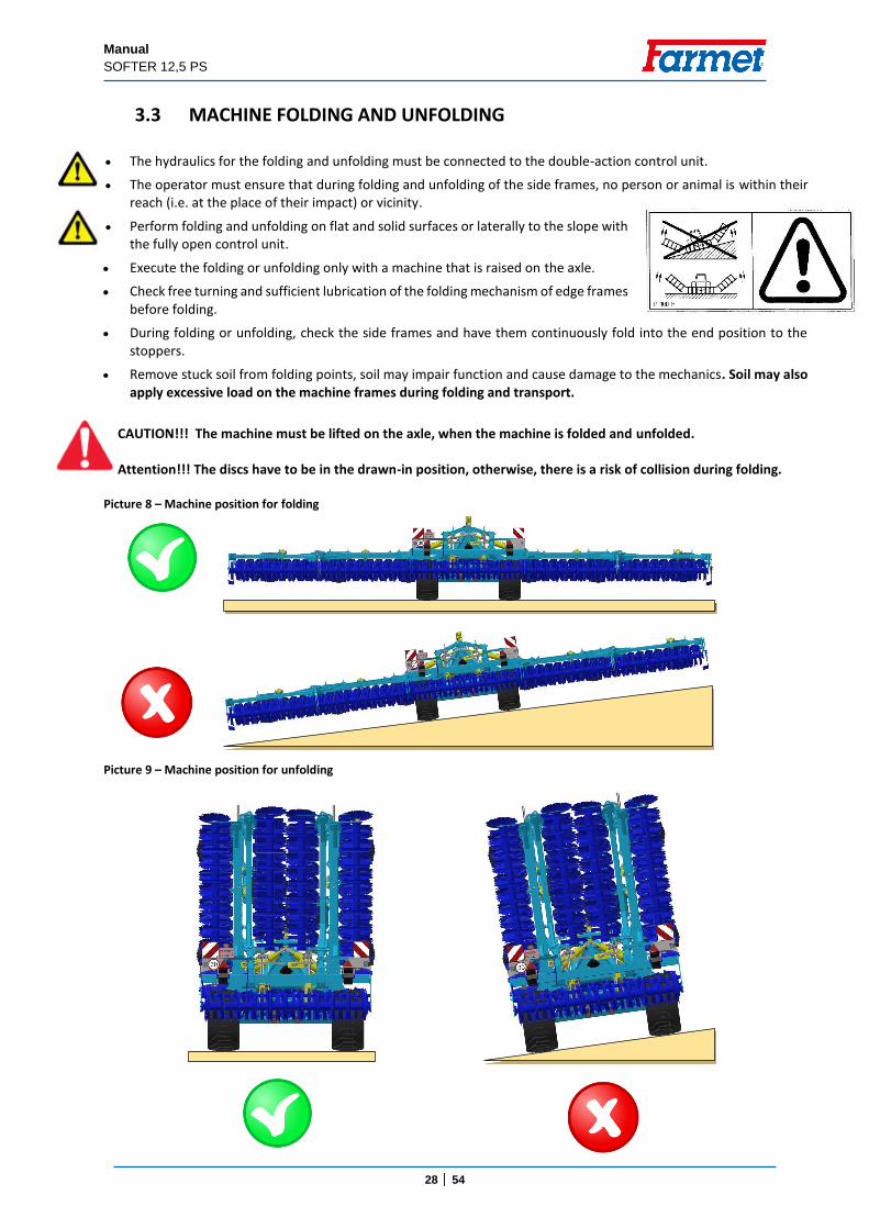
CAUTION!!! The machine must be lifted on the axle, when the machine is folded and unfolded. Attention!!! The discs have to be in the drawn-in position, otherwise, there is a risk of collision during folding.
Picture 8 – Machine position for folding
Picture 9 – Machine position for unfolding
Manual
SOFTER 12,5 PS
29 │ 54
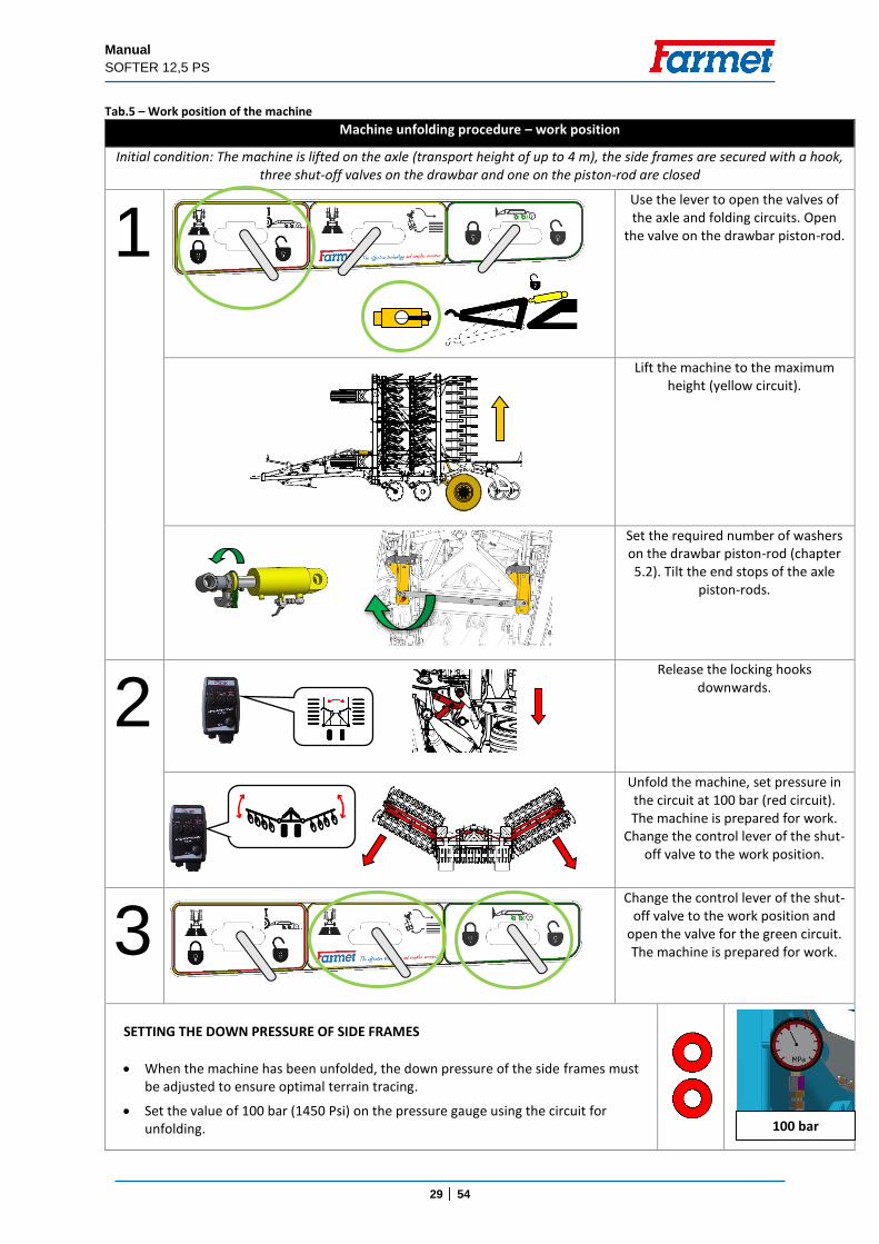
Tab.5 – Work position of the machine
Machine unfolding procedure – work position
Initial condition: The machine is lifted on the axle (transport height of up to 4 m), the side frames are secured with a hook, three shut-off valves on the drawbar and one on the piston-rod are closed
1 Use the lever to open the valves of
the axle and folding circuits. Open the valve on the drawbar piston-rod.
Lift the machine to the maximum height (yellow circuit).
Set the required number of washers on the drawbar piston-rod (chapter 5.2). Tilt the end stops of the axle
piston-rods.
2 Release the locking hooks
downwards.
Unfold the machine, set pressure in the circuit at 100 bar (red circuit). The machine is prepared for work.
Change the control lever of the shut-off valve to the work position.
3 Change the control lever of the shut-
off valve to the work position and open the valve for the green circuit. The machine is prepared for work.
SETTING THE DOWN PRESSURE OF SIDE FRAMES
When the machine has been unfolded, the down pressure of the side frames must be adjusted to ensure optimal terrain tracing.
Set the value of 100 bar (1450 Psi) on the pressure gauge using the circuit for unfolding.
100 bar
Manual
SOFTER 12,5 PS
30 │ 54
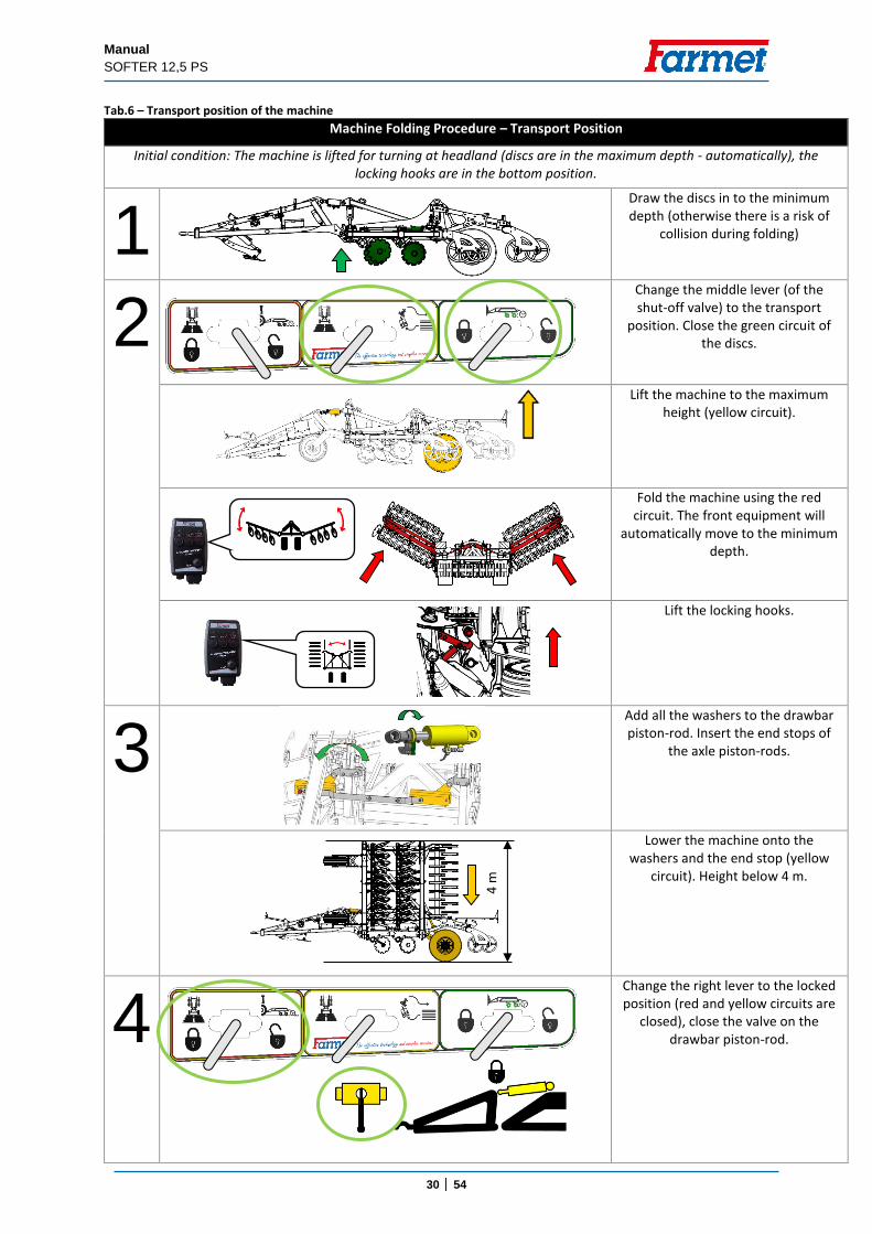
Tab.6 – Transport position of the machine
Machine Folding Procedure – Transport Position
Initial condition: The machine is lifted for turning at headland (discs are in the maximum depth - automatically), the locking hooks are in the bottom position.
1 Draw the discs in to the minimum
depth (otherwise there is a risk of collision during folding)
2 Change the middle lever (of the
shut-off valve) to the transport position. Close the green circuit of
the discs.
Lift the machine to the maximum height (yellow circuit).
Fold the machine using the red circuit. The front equipment will
automatically move to the minimum depth.
Lift the locking hooks.
3
Add all the washers to the drawbar piston-rod. Insert the end stops of
the axle piston-rods.
Lower the machine onto the washers and the end stop (yellow
circuit). Height below 4 m.
4 ;
Change the right lever to the locked position (red and yellow circuits are
closed), close the valve on the drawbar piston-rod.
4 m
;
Manual
SOFTER 12,5 PS
31 │ 54
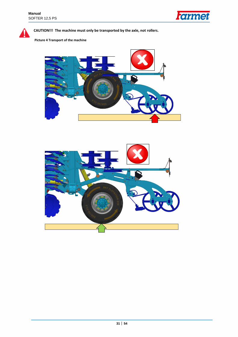
CAUTION!!! The machine must only be transported by the axle, not rollers.
Picture 4 Transport of the machine
Manual
SOFTER 12,5 PS
32 │ 54
4. MACHINE TRANSPORT ON ROADS
Transport position of SOFTER 12,5 PS Connect the machine to the tractor by the fixed bottom hitch using a pin or a ball.
Bring the machine into the transport position (according to Tab.6)
The height must be lower than 4 metres. The machine is lowered on the washers of the drawbar piston-rod and on the end stops of the axle.
The machine must be equipped with removable shields with marking of contours, functional lighting, and the board of the rear marking for slow vehicles (according to ECE No. 69).
The lighting must be activated during travelling on roads.
The tractor must be equipped with a special light device of an orange colour, which must be activated during travelling on roads.
When the machine is equipped with a brake system, it has to be connected to the tractor when driving.
The maximum transport speed during travelling on roads is 30 km/h (18.6 mph).
Ban of transport with decreased visibility!
The operator is obliged to pay increased attention during transport on roads, due to the transport dimensions of
the machine.
The operator must observe the valid regulations for transport on roads (laws, decrees) after connecting the machine to the tractor, for reason of a change of the axle load. The driving properties of the set also change depending on the terrain nature, adapt the manner of driving to these conditions.
Only machines with a valid technical certificate issued in accordance with the valid regulation on the approval of technical qualification and operation on public communications as amended may be transported on public communications. Machines without a valid technical certificate may only be transported on public communications when carried by a towed trailer or other approved means of transport in accordance with the valid regulation.
The operator is obliged to secure sufficient outlook during reversing from his position of the tractor driver. In case of insufficient outlook, the operator is obliged to call a competent and informed person.
The operator must fold the side frames for transport and secure then against unwanted unfolding by disconnecting the hydraulic circuit of the machine and the tractor.
During machine transport on roads, the operator must observe the valid laws and decrees that deal with this topic and which specify the relationships of the tractor axle load depending on transport speed.
Clean the entire machine from any accumulated soil before the transportation on the road.
Manual
SOFTER 12,5 PS
33 │ 54
5. MACHINE ADJUSTMENT
5.1 MACHINE WORKING DEPTH ADJTUSTMENT
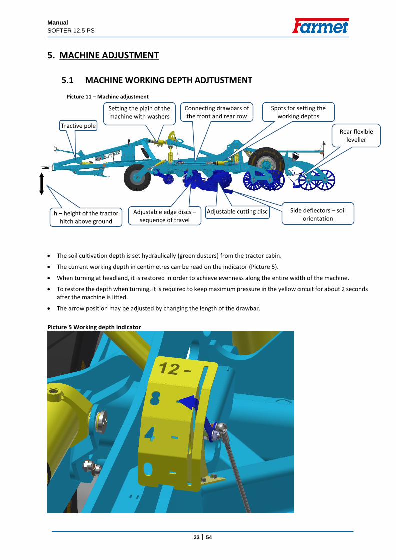
The soil cultivation depth is set hydraulically (green dusters) from the tractor cabin.
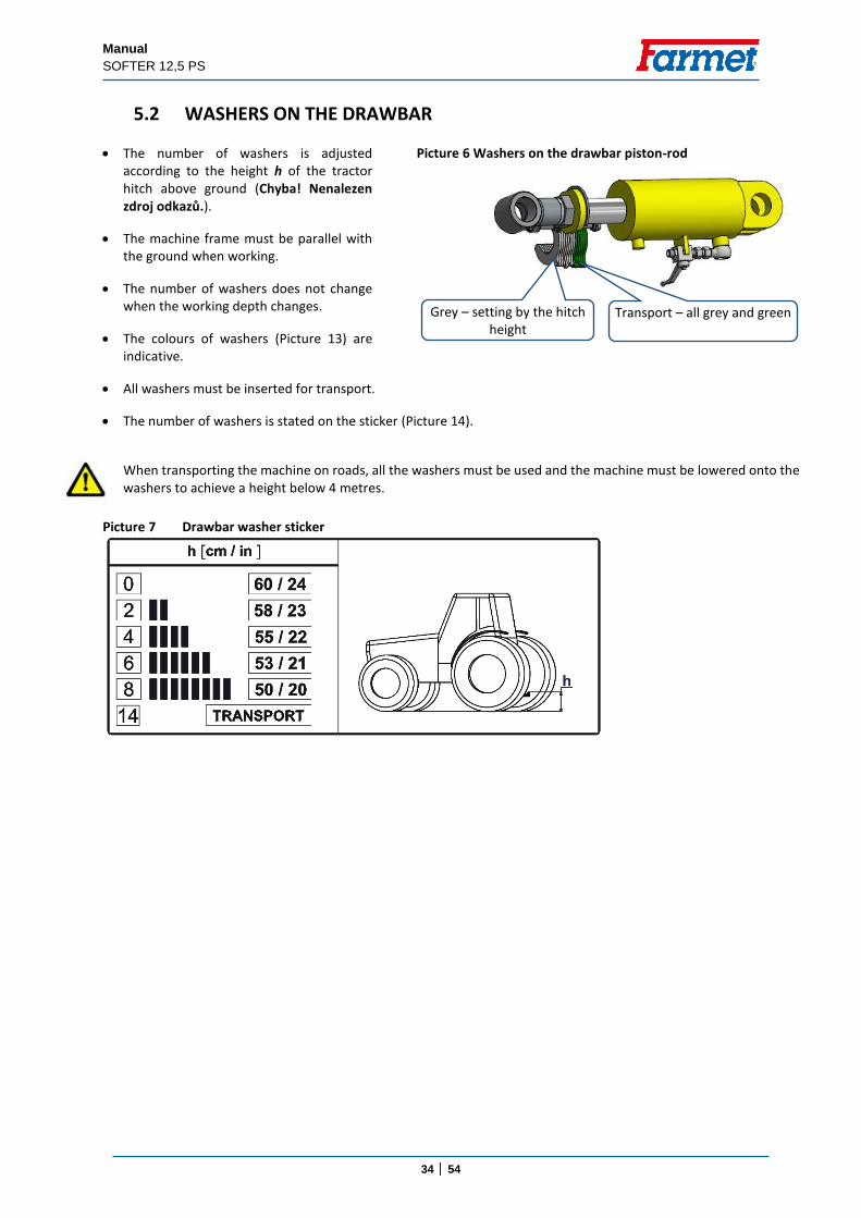
The current working depth in centimetres can be read on the indicator (Picture 5).
When turning at headland, it is restored in order to achieve evenness along the entire width of the machine.
To restore the depth when turning, it is required to keep maximum pressure in the yellow circuit for about 2 seconds after the machine is lifted.
The arrow position may be adjusted by changing the length of the drawbar.
Picture 5 Working depth indicator
Picture 11 – Machine adjustment
Tractive pole
Setting the plain of the machine with washers
Connecting drawbars of the front and rear row
Adjustable edge discs –sequence of travel
Side deflectors – soil orientation
Spots for setting the working depths
h – height of the tractor hitch above ground
Adjustable cutting disc
Rear flexible leveller
Manual
SOFTER 12,5 PS
34 │ 54
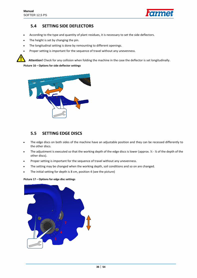
5.2 WASHERS ON THE DRAWBAR
The number of washers is adjusted according to the height h of the tractor hitch above ground (Chyba! Nenalezen zdroj odkazů.).
The machine frame must be parallel with the ground when working.
The number of washers does not change when the working depth changes.
The colours of washers (Picture 13) are indicative.
All washers must be inserted for transport.
The number of washers is stated on the sticker (Picture 14).
When transporting the machine on roads, all the washers must be used and the machine must be lowered onto the washers to achieve a height below 4 metres.
Picture 6 Washers on the drawbar piston-rod
Grey – setting by the hitch height
Transport – all grey and green
Picture 7 Drawbar washer sticker

Manual
SOFTER 12,5 PS
35 │ 54
5.3 SETTING THE FRONT EQUIPMENT
The front equipment is set from the cabin by the blue hydraulic circuit.
The machine may be equipped with a cutting roller or a flexible leveller.
The position is shown on the piston-rod indicator (Picture 15).
Position 4 – highest labour intensity.
Position 1 – deactivated.
The setting is independent of the disc working depth setting.
There are flow limiters in the circuit.
It may be deactivated when there is a large quantity of crop residue (marked position 1.
An excessive down pressure on the front cutting roller may worsen recessing of the discs.
Picture 8 Front equipment indicator
Manual
SOFTER 12,5 PS
36 │ 54
5.4 SETTING SIDE DEFLECTORS According to the type and quantity of plant residues, it is necessary to set the side deflectors.
The height is set by changing the pin.
The longitudinal setting is done by remounting to different openings.
Proper setting is important for the sequence of travel without any unevenness.
Attention! Check for any collision when folding the machine in the case the deflector is set longitudinally.
5.5 SETTING EDGE DISCS
The edge discs on both sides of the machine have an adjustable position and they can be recessed differently to the other discs.
The adjustment is executed so that the working depth of the edge discs is lower (approx. ½ - ¼ of the depth of the other discs).
Proper setting is important for the sequence of travel without any unevenness.
The setting may be changed when the working depth, soil conditions and so on are changed.
The initial setting for depth is 8 cm, position 4 (see the picture)
Picture 16 – Options for side deflector settings
Picture 17 – Options for edge disc settings
1
4
7
Manual
SOFTER 12,5 PS
37 │ 54
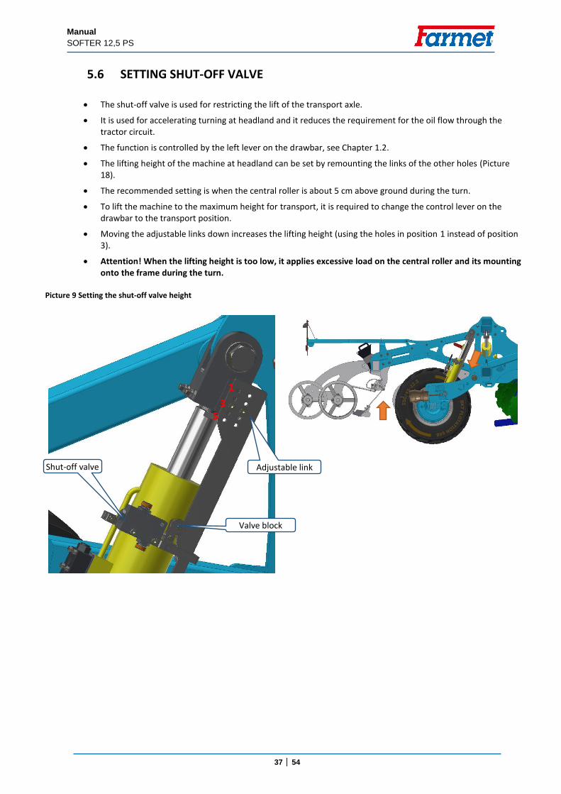
5.6 SETTING SHUT-OFF VALVE
The shut-off valve is used for restricting the lift of the transport axle.
It is used for accelerating turning at headland and it reduces the requirement for the oil flow through the tractor circuit.
The function is controlled by the left lever on the drawbar, see Chapter 1.2.
The lifting height of the machine at headland can be set by remounting the links of the other holes (Picture 18).
The recommended setting is when the central roller is about 5 cm above ground during the turn.
To lift the machine to the maximum height for transport, it is required to change the control lever on the drawbar to the transport position.
Moving the adjustable links down increases the lifting height (using the holes in position 1 instead of position 3).
Attention! When the lifting height is too low, it applies excessive load on the central roller and its mounting onto the frame during the turn.
Picture 9 Setting the shut-off valve height
Adjustable link Shut-off valve
Valve block
3
1
5
Manual
SOFTER 12,5 PS
38 │ 54
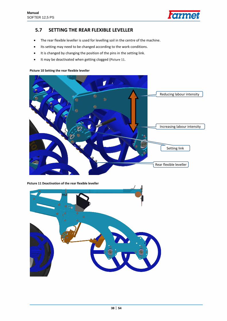
5.7 SETTING THE REAR FLEXIBLE LEVELLER
The rear flexible leveller is used for levelling soil in the centre of the machine.
Its setting may need to be changed according to the work conditions.
It is changed by changing the position of the pins in the setting link.
It may be deactivated when getting clogged (Picture 11.
Picture 11 Deactivation of the rear flexible leveller
Picture 10 Setting the rear flexible leveller
Rear flexible leveller
Setting link
Increasing labour intensity
Reducing labour intensity
Manual
SOFTER 12,5 PS
39 │ 54
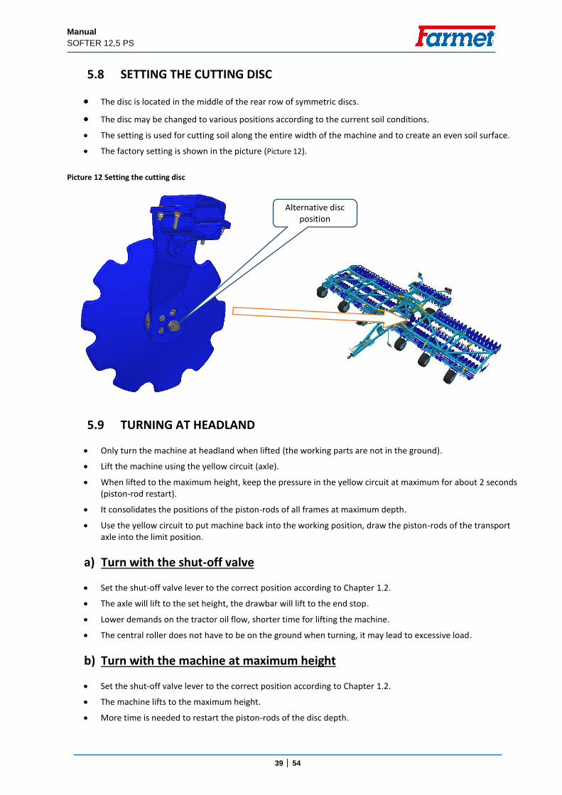
5.8 SETTING THE CUTTING DISC
The disc is located in the middle of the rear row of symmetric discs.
The disc may be changed to various positions according to the current soil conditions.
The setting is used for cutting soil along the entire width of the machine and to create an even soil surface.
The factory setting is shown in the picture (Picture 12).
Picture 12 Setting the cutting disc
5.9 TURNING AT HEADLAND
Only turn the machine at headland when lifted (the working parts are not in the ground).
Lift the machine using the yellow circuit (axle).
When lifted to the maximum height, keep the pressure in the yellow circuit at maximum for about 2 seconds (piston-rod restart).
It consolidates the positions of the piston-rods of all frames at maximum depth.
Use the yellow circuit to put machine back into the working position, draw the piston-rods of the transport axle into the limit position.
a) Turn with the shut-off valve
Set the shut-off valve lever to the correct position according to Chapter 1.2.
The axle will lift to the set height, the drawbar will lift to the end stop.
Lower demands on the tractor oil flow, shorter time for lifting the machine.
The central roller does not have to be on the ground when turning, it may lead to excessive load.
b) Turn with the machine at maximum height
Set the shut-off valve lever to the correct position according to Chapter 1.2.
The machine lifts to the maximum height.
More time is needed to restart the piston-rods of the disc depth.
Alternative disc position
disku
Manual
SOFTER 12,5 PS
40 │ 54
6. ELECTRONIC HYDRAULIC CIRCUIT SWITCH
6.1 DESCRIPTION OF THE EQUIPMENT
The product is designed for electronic division and control of the hydraulic circuits. Primarily, the system has one input circuit and three output circuits, while the selection of the individual circuits is done via an electronic controller from the tractor cabin.
Thus, we are reducing the final number of connected hydraulic circuits between the tractor and the machine.
6.2 SYSTEM WIRING DIAGRAM
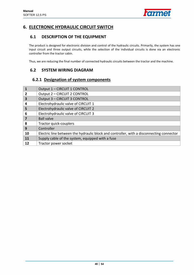
6.2.1 Designation of system components
1 Output 1 – CIRCUIT 1 CONTROL
2 Output 2 – CIRCUIT 2 CONTROL
3 Output 3 – CIRCUIT 3 CONTROL
4 Electrohydraulic valve of CIRCUIT 1
5 Electrohydraulic valve of CIRCUIT 2
6 Electrohydraulic valve of CIRCUIT 3
7 Ball valve
8 Tractor quick-couplers
9 Controller
10 Electric line between the hydraulic block and controller, with a disconnecting connector
11 Supply cable of the system, equipped with a fuse
12 Tractor power socket

Manual
SOFTER 12,5 PS
41 │ 54
6.2.2 Wiring diagram
Manual
SOFTER 12,5 PS
42 │ 54
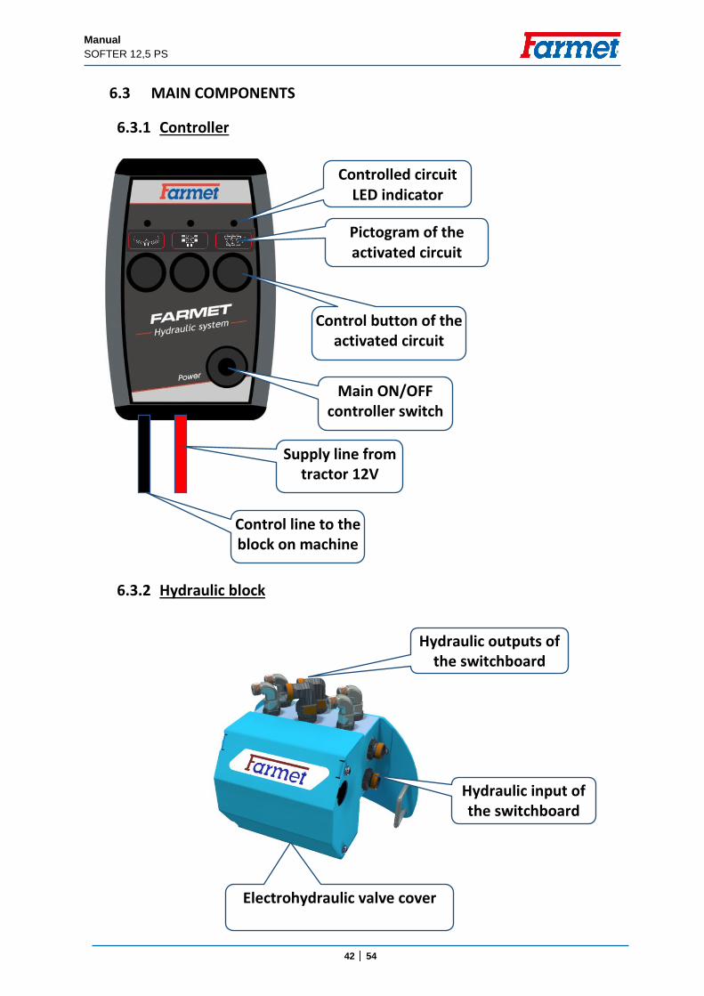
6.3 MAIN COMPONENTS
6.3.1 Controller
6.3.2 Hydraulic block
Main ON/OFF controller switch
Control button of the activated circuit
Pictogram of the activated circuit
Controlled circuit LED indicator
Supply line from tractor 12V
Control line to the block on machine
Hydraulic outputs of the switchboard
Hydraulic input of the switchboard
Electrohydraulic valve cover
Manual
SOFTER 12,5 PS
43 │ 54
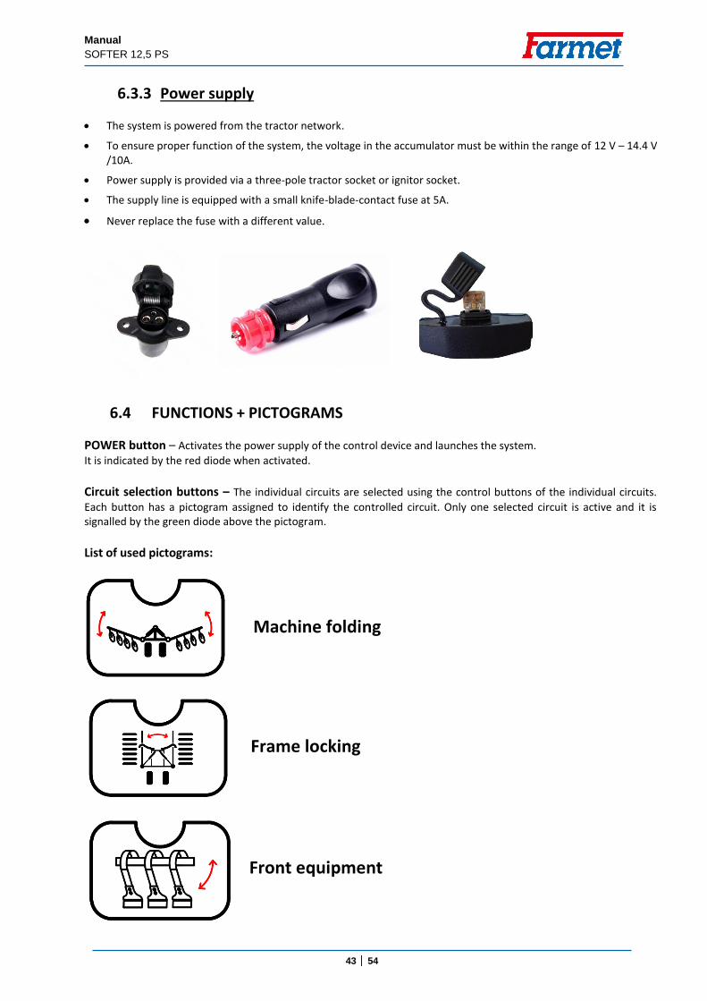
6.3.3 Power supply
The system is powered from the tractor network.
To ensure proper function of the system, the voltage in the accumulator must be within the range of 12 V – 14.4 V /10A.
Power supply is provided via a three-pole tractor socket or ignitor socket.
The supply line is equipped with a small knife-blade-contact fuse at 5A.
Never replace the fuse with a different value.
6.4 FUNCTIONS + PICTOGRAMS
POWER button – Activates the power supply of the control device and launches the system.
It is indicated by the red diode when activated.
Circuit selection buttons – The individual circuits are selected using the control buttons of the individual circuits.
Each button has a pictogram assigned to identify the controlled circuit. Only one selected circuit is active and it is signalled by the green diode above the pictogram.
List of used pictograms:
Frame locking
Machine folding
Front equipment
Manual
SOFTER 12,5 PS
44 │ 54
6.5 CONNECTING PROCEDURE
1. Installation of the controller in the tractor cabin
2. Connection with the machine
3. Connection with the electric source
4. System activation using the Power button
5. Circuit selection
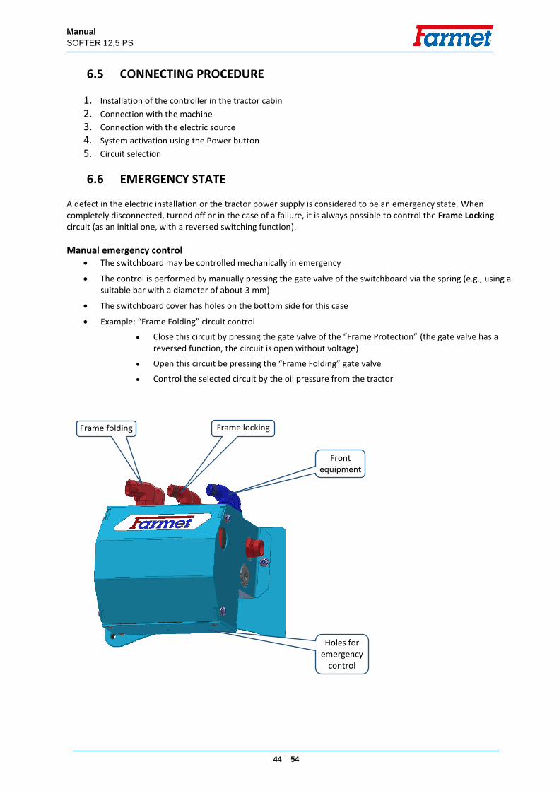
6.6 EMERGENCY STATE
A defect in the electric installation or the tractor power supply is considered to be an emergency state. When completely disconnected, turned off or in the case of a failure, it is always possible to control the Frame Locking circuit (as an initial one, with a reversed switching function).
Manual emergency control The switchboard may be controlled mechanically in emergency
The control is performed by manually pressing the gate valve of the switchboard via the spring (e.g., using a suitable bar with a diameter of about 3 mm)
The switchboard cover has holes on the bottom side for this case
Example: “Frame Folding” circuit control
Close this circuit by pressing the gate valve of the “Frame Protection” (the gate valve has a reversed function, the circuit is open without voltage)
Open this circuit be pressing the “Frame Folding” gate valve
Control the selected circuit by the oil pressure from the tractor
Holes for emergency
control
Front equipment
Frame locking Frame folding
Manual
SOFTER 12,5 PS
45 │ 54
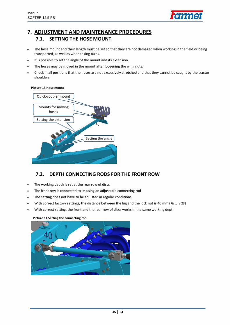
7. ADJUSTMENT AND MAINTENANCE PROCEDURES 7.1. SETTING THE HOSE MOUNT
The hose mount and their length must be set so that they are not damaged when working in the field or being transported, as well as when taking turns.
It is possible to set the angle of the mount and its extension.
The hoses may be moved in the mount after loosening the wing nuts.
Check in all positions that the hoses are not excessively stretched and that they cannot be caught by the tractor shoulders
7.2. DEPTH CONNECTING RODS FOR THE FRONT ROW
The working depth is set at the rear row of discs
The front row is connected to its using an adjustable connecting rod
The setting does not have to be adjusted in regular conditions
With correct factory settings, the distance between the lug and the lock nut is 40 mm (Picture 23)
With correct setting, the front and the rear row of discs works in the same working depth
Picture 14 Setting the connecting rod
Quick-coupler mount
Mounts for moving hoses
Setting the extension
Setting the angle
Picture 13 Hose mount
Manual
SOFTER 12,5 PS
46 │ 54
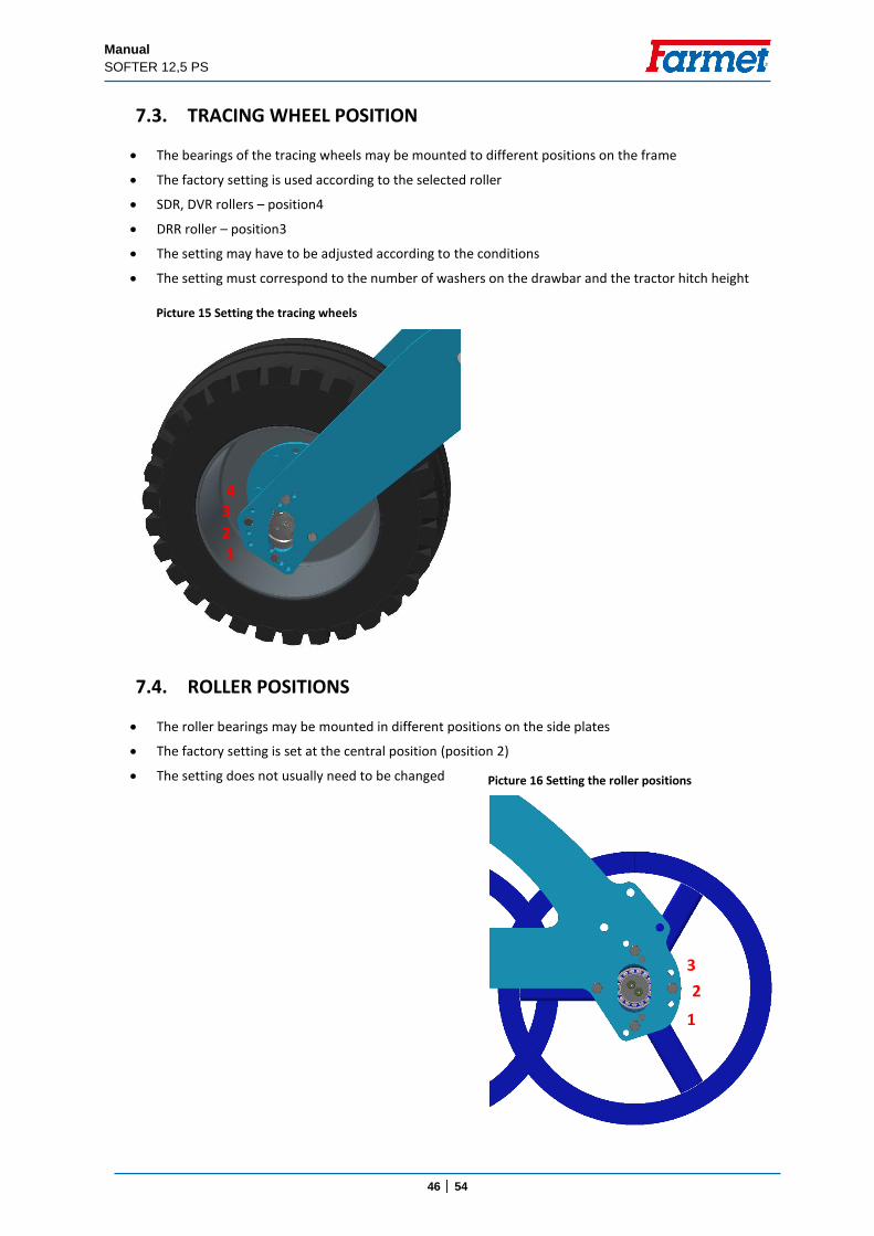
7.3. TRACING WHEEL POSITION
The bearings of the tracing wheels may be mounted to different positions on the frame
The factory setting is used according to the selected roller
SDR, DVR rollers – position4
DRR roller – position3
The setting may have to be adjusted according to the conditions
The setting must correspond to the number of washers on the drawbar and the tractor hitch height
7.4. ROLLER POSITIONS
The roller bearings may be mounted in different positions on the side plates
The factory setting is set at the central position (position 2)
The setting does not usually need to be changed
1 2 3 4
Picture 15 Setting the tracing wheels
1
2
3
Picture 16 Setting the roller positions
Manual
SOFTER 12,5 PS
47 │ 54
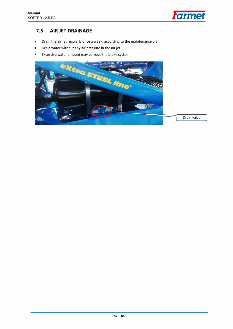
7.5. AIR JET DRAINAGE
Drain the air jet regularly once a week, according to the maintenance plan.
Drain water without any air pressure in the air jet
Excessive water amount may corrode the brake system
Drain valve
Manual
SOFTER 12,5 PS
48 │ 54
8. MACHINE MAINTENANCE AND REPAIRS Observe the safety instructions for treatment and maintenance.
If it is necessary to weld during the repair and have the machine connected to the tractor, it must have disconnected supply cables from the alternator and the accumulator.
Check the tightening of all screw and other assembly connections at the machine before every use of the machine, furthermore continuously as needed.
Continuously check the wear of the working bodies of the machine, possibly replace these worn working bodies with new ones.
Adjustment, cleaning, and lubrication of the machine may only be performed with the machine at rest (i.e. the machine is standing and not working).
When working on a lifted machine, use suitable support equipment supported at marked points or at points suitable for that.
During adjustment, cleaning, maintenance, and repair of the machine, you must secure those parts of the machine that could endanger the operator by falling or another movement.
For catching the machine during handling using lifting equipment, use only the places marked with self-adhesive labels with the chain sign " ".
Upon a failure or damage of the machine, immediately turn off the tractor's engine and secure against restarting,
secure the machine against movement only then you can remove the failure.
During repairs of the machine, use exclusively the genuine spare parts, suitable tools and protective equipment.
Regularly check the prescribed pressure in the machine tyres and the condition of the tyres. Perform possible repairs of the tyres in an expert workshop.
Keep the machine clean.
Do not clean hydraulic cylinders and bearings with a high-pressure cleaner or direct water stream. The seals and bearings are not watertight at high pressure.
Manual
SOFTER 12,5 PS
49 │ 54
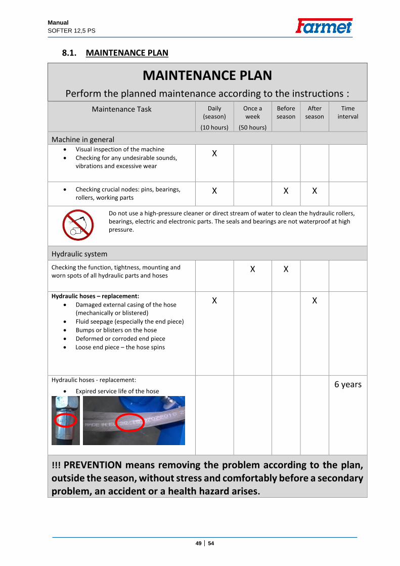
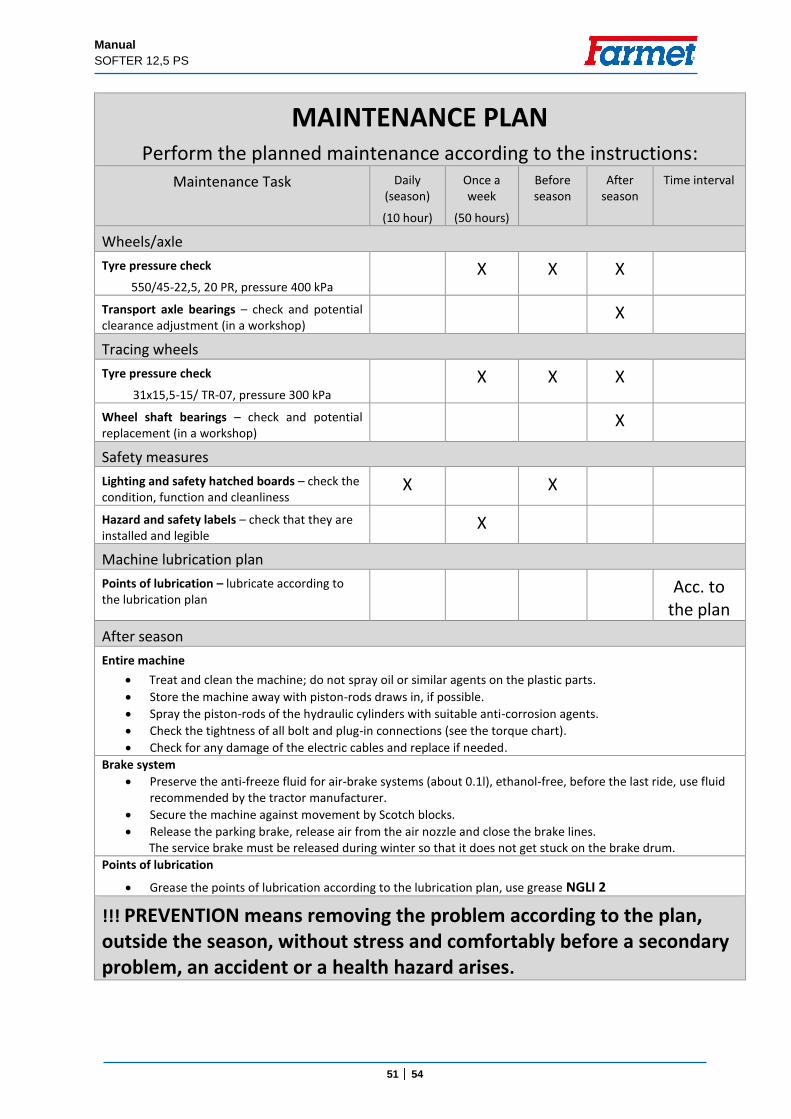
8.1. MAINTENANCE PLAN
MAINTENANCE PLAN
Perform the planned maintenance according to the instructions :
Maintenance Task Daily (season)
(10 hours)
Once a week
(50 hours)
Before season
After season
Time interval
Machine in general Visual inspection of the machine
Checking for any undesirable sounds, vibrations and excessive wear
X
Checking crucial nodes: pins, bearings, rollers, working parts
X X X
Do not use a high-pressure cleaner or direct stream of water to clean the hydraulic rollers, bearings, electric and electronic parts. The seals and bearings are not waterproof at high pressure.
Hydraulic system
Checking the function, tightness, mounting and worn spots of all hydraulic parts and hoses
X X
Hydraulic hoses – replacement:
Damaged external casing of the hose (mechanically or blistered)
Fluid seepage (especially the end piece)
Bumps or blisters on the hose
Deformed or corroded end piece
Loose end piece – the hose spins
X X
Hydraulic hoses - replacement:
Expired service life of the hose
6 years
!!! PREVENTION means removing the problem according to the plan, outside the season, without stress and comfortably before a secondary problem, an accident or a health hazard arises.
Manual
SOFTER 12,5 PS
50 │ 54
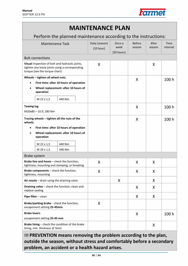
MAINTENANCE PLAN
Perform the planned maintenance according to the instructions:
Maintenance Task Daily (season)
(10 hour)
Once a week
(50 hours)
Before season
After season
Time interval
Bolt connections
Visual inspection of bolt and hydraulic joints, tighten any loose joints using a corresponding torque (see the torque chart)
X X
Wheels – tighten all wheel nuts.
First time: after 10 hours of operation
Wheel replacement: after 10 hours of operation
M 22 x 1,5 440 Nm
X 100 h
Towing lug
M20x80 – 10.9, 280 Nm
X 100 h
Tracing wheels – tighten all the nuts of the wheels.
First time: after 10 hours of operation
Wheel replacement: after 10 hours of operation
M 22 x 1,5 440 Nm
M 20 x 1,5 340 Nm
X 100 h
Brake system
Brake line and hoses – check the function, tightness, mounting and clamping, or breaking
X X X
Brake components – check the function, tightness, mounting
X X X
Air nozzle – drain using the draining valve X X
Draining valve – check the function, clean and replace sealing
X X
Pipe filter – clean X X
Brake/parking brake – check the function, escapement setting 25-45mm
X
Brake levers
escapement setting 25-45 mm
X 100 h
Brake lining – check the condition of the brake lining, min. thickness of 3mm
X
!!! PREVENTION means removing the problem according to the plan, outside the season, without stress and comfortably before a secondary problem, an accident or a health hazard arises.
Manual
SOFTER 12,5 PS
51 │ 54
MAINTENANCE PLAN
Perform the planned maintenance according to the instructions:
Maintenance Task Daily (season)
(10 hour)
Once a week
(50 hours)
Before season
After season
Time interval
Wheels/axle
Tyre pressure check
550/45-22,5, 20 PR, pressure 400 kPa
X X X
Transport axle bearings – check and potential clearance adjustment (in a workshop)
X
Tracing wheels
Tyre pressure check
31x15,5-15/ TR-07, pressure 300 kPa
X X X
Wheel shaft bearings – check and potential replacement (in a workshop)
X
Safety measures
Lighting and safety hatched boards – check the condition, function and cleanliness
X X
Hazard and safety labels – check that they are installed and legible
X
Machine lubrication plan
Points of lubrication – lubricate according to the lubrication plan
Acc. to the plan
After season
Entire machine
Treat and clean the machine; do not spray oil or similar agents on the plastic parts.
Store the machine away with piston-rods draws in, if possible.
Spray the piston-rods of the hydraulic cylinders with suitable anti-corrosion agents.
Check the tightness of all bolt and plug-in connections (see the torque chart).
Check for any damage of the electric cables and replace if needed. Brake system
Preserve the anti-freeze fluid for air-brake systems (about 0.1l), ethanol-free, before the last ride, use fluid recommended by the tractor manufacturer.
Secure the machine against movement by Scotch blocks. Release the parking brake, release air from the air nozzle and close the brake lines.
The service brake must be released during winter so that it does not get stuck on the brake drum. Points of lubrication
Grease the points of lubrication according to the lubrication plan, use grease NGLI 2
!!! PREVENTION means removing the problem according to the plan, outside the season, without stress and comfortably before a secondary problem, an accident or a health hazard arises.
Manual
SOFTER 12,5 PS
52 │ 54
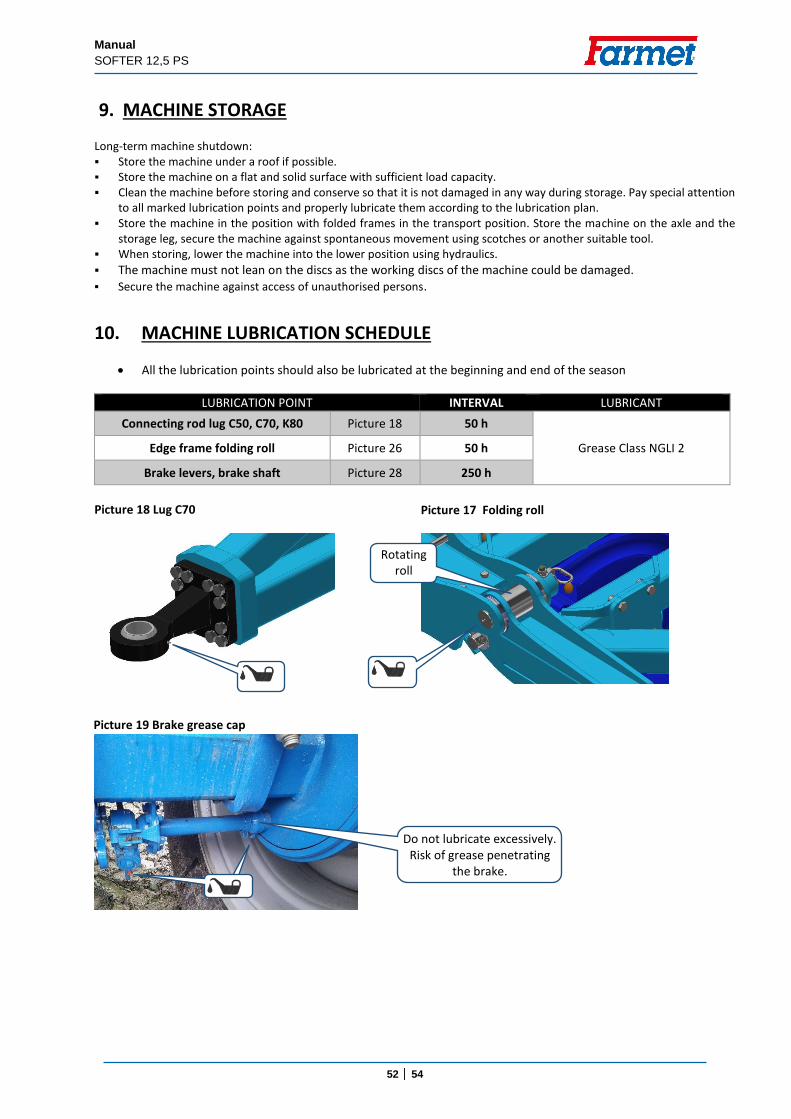
9. MACHINE STORAGE Long-term machine shutdown: Store the machine under a roof if possible. Store the machine on a flat and solid surface with sufficient load capacity. Clean the machine before storing and conserve so that it is not damaged in any way during storage. Pay special attention
to all marked lubrication points and properly lubricate them according to the lubrication plan. Store the machine in the position with folded frames in the transport position. Store the machine on the axle and the
storage leg, secure the machine against spontaneous movement using scotches or another suitable tool. When storing, lower the machine into the lower position using hydraulics.
The machine must not lean on the discs as the working discs of the machine could be damaged. Secure the machine against access of unauthorised persons.
10. MACHINE LUBRICATION SCHEDULE
All the lubrication points should also be lubricated at the beginning and end of the season
LUBRICATION POINT INTERVAL LUBRICANT
Connecting rod lug C50, C70, K80 Picture 18 50 h
Grease Class NGLI 2 Edge frame folding roll Picture 26 50 h
Brake levers, brake shaft Picture 28 250 h
Picture 18 Lug C70
Rotating roll
Picture 17 Folding roll
Do not lubricate excessively. Risk of grease penetrating
the brake.
Picture 19 Brake grease cap
Manual
SOFTER 12,5 PS
53 │ 54
11. ENVIRONMENTAL PROTECTION Regularly check the tightness of the hydraulic system. Preventively replace or repair hydraulic hoses, possibly further parts of the hydraulic system showing signs of
damage, before oil leaks occur. Check the condition of hydraulic hoses and perform their timely replacement. The service life of hydraulic hoses
includes the time, when they were stored. Handle oils and greases according to valid waste laws and regulations
12. MACHINE DISPOSAL AFTER SERVICE LIFE EXPIRY The operator must secure during machine disposal that steel parts and parts, in which hydraulic oil or lubricating
grease moves are differentiated. Steel parts must be cut by the operator while observing safety regulations and handed over to the secondary raw
material collection point. He must proceed with other parts according to valid laws about waste.
13. SERVICING AND WARANTY CONDITIONS 13.1. SERVICING Servicing is secured by the dealer after consulting with the manufacturer, possibly directly by the
manufacturer. Spare parts then using the sales network by individual sellers in the entire country. Use only the spare parts according to the spare parts catalogue officially issued by the manufacturer.
13.2. WARRANTY 13.2.1 The manufacturer provides a warranty of 24 months for these machine parts: main frame, axle, and
machine tow bar. For other parts of the machine, the manufacturer provides a warranty of 12 months. The warranty is provided from the date of sale of the new machine to the end user (consumer).
13.2.2 The warranty applies to hidden defects that will show in the warranty period with proper use of the machine and while fulfilling the conditions stated in the operating manual.
13.2.3 The warranty does not apply to wearable spare parts, i.e. regular mechanical wear and tear of replaceable parts of the working sections (shares, edges, etc.).
13.2.4 The warranty does not apply to indirect consequences of possible damage, such as service life decrease etc.
13.2.5 The warranty is bound to the machine and is not void upon an owner change.
13.2.6 The warranty is limited to the disassembly and assembly, possibly replacement or repair of the defective part. The decision, whether to replace or repair the defective part, is up to the contractual workshop of Farmet.
13.2.7 During the warranty period, only the authorised servicing technician of the manufacturer may perform repairs or other interventions into the machine. In the opposite case, the warranty will not be acknowledged. This provision does not apply to the replacement of wearable spare parts (see point 13.2.3).
13.2.8 The warranty is conditioned by using the genuine spare parts of the manufacturer.
Prepared by: Technical Department, Farmet a.s., Jirinkova 276, Ceska Skalice 552 03, On 8 October 2020, changes reserved.
54 │ 54
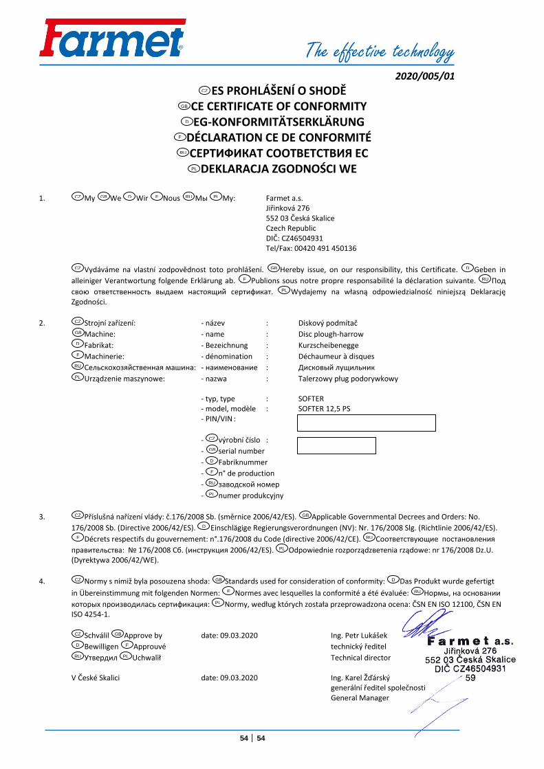
2020/005/01
ES PROHLÁŠENÍ O SHODĚ CE CERTIFICATE OF CONFORMITY EG-KONFORMITÄTSERKLÄRUNG
DÉCLARATION CE DE CONFORMITÉ СЕРТИФИКАТ СООТВЕТСТВИЯ ЕС
DEKLARACJA ZGODNOŚCI WE
1. My We Wir Nous Мы My: Farmet a.s. Jiřinková 276 552 03 Česká Skalice Czech Republic DIČ: CZ46504931 Tel/Fax: 00420 491 450136
Vydáváme na vlastní zodpovědnost toto prohlášení. Hereby issue, on our responsibility, this Certificate. Geben in
alleiniger Verantwortung folgende Erklärung ab. Publions sous notre propre responsabilité la déclaration suivante. Под
свою ответственность выдаем настоящий сертификат. Wydajemy na własną odpowiedzialność niniejszą Deklarację Zgodności.
2. Strojní zařízení: - název : Diskový podmítač
Machine: - name : Disc plough-harrow
Fabrikat: - Bezeichnung : Kurzscheibenegge
Machinerie: - dénomination : Déchaumeur à disques
Сельскохозяйственная машина: - наименование : Дисковый лущильник
Urządzenie maszynowe: - nazwa : Talerzowy pług podorywkowy - typ, type : SOFTER - model, modèle : SOFTER 12,5 PS - PIN/VIN :
- výrobní číslo :
- serial number
- Fabriknummer
- n° de production
- заводской номер
- numer produkcyjny
3. Příslušná nařízení vlády: č.176/2008 Sb. (směrnice 2006/42/ES). Applicable Governmental Decrees and Orders: No.
176/2008 Sb. (Directive 2006/42/ES). Einschlägige Regierungsverordnungen (NV): Nr. 176/2008 Slg. (Richtlinie 2006/42/ES).
Décrets respectifs du gouvernement: n°.176/2008 du Code (directive 2006/42/CE). Соответствующие постановления
правительства: № 176/2008 Сб. (инструкция 2006/42/ES). Odpowiednie rozporządzветenia rządowe: nr 176/2008 Dz.U. (Dyrektywa 2006/42/WE).
4. Normy s nimiž byla posouzena shoda: Standards used for consideration of conformity: Das Produkt wurde gefertigt
in Übereinstimmung mit folgenden Normen: Normes avec lesquelles la conformité a été évaluée: Нормы, на основании
которых производилась сертификация: Normy, według których została przeprowadzona ocena: ČSN EN ISO 12100, ČSN EN ISO 4254-1.
Schválil Approve by date: 09.03.2020 Ing. Petr Lukášek
Bewilligen Approuvé technický ředitel
Утвеpдил Uchwalił Technical director V České Skalici date: 09.03.2020 Ing. Karel Žďárský generální ředitel společnosti General Manager
CZ
GB
D
F
RU
PL
CZ GB D F RU PL
CZ GB D
F RU
PL
CZ
GB
D
F
RU
PL
CZ
GB
D
F
RU
PL
CZ GB
D
F RU
PL
CZ GB D
F RU
PL
CZ GB
D F
RU PL