Embed Size (px)
Citation preview
Software
Motors | Automation | Energy | Transmission & Distribution | Coatings
SuperDrive 7.0.0
User's Manual

User's Manual
Language: English
Document: 10001830633 / 01
Publication Date: 08/31/2015
Series: SuperDrive
Content
SuperDrive 7.0.0 | 3
Content
1 SuperDrive 7.0.0 5
................................................................................................................................... 51 Welcome
................................................................................................................................... 52 Main Features
................................................................................................................................... 63 What's New
................................................................................................................................... 64 Migrating from Previous Versions
................................................................................................................................... 65 Copyright Notice
................................................................................................................................... 66 Safety Warning
................................................................................................................................... 77 User's Manual - PDF
................................................................................................................................... 78 License
2 Installation Instructions 8
................................................................................................................................... 81 Before Installing SuperDrive
................................................................................................................................... 82 Minimum Requirements
................................................................................................................................... 93 Supported Drives
................................................................................................................................... 154 Installing SuperDrive
................................................................................................................................... 165 Uninstalling SuperDrive
3 SuperDrive Structure 17
................................................................................................................................... 171 SuperDrive Architecture
................................................................................................................................... 182 Project Architecture
4 Menus 20
................................................................................................................................... 211 Project
......................................................................................................................................................... 21New
......................................................................................................................................................... 21Open
......................................................................................................................................................... 22Close
......................................................................................................................................................... 22Save As
......................................................................................................................................................... 22Remove
......................................................................................................................................................... 23Print Setup
......................................................................................................................................................... 23Print
......................................................................................................................................................... 24Exit
................................................................................................................................... 242 View
......................................................................................................................................................... 24ToolBar
......................................................................................................................................................... 24DriveBar
......................................................................................................................................................... 25StatusBar
................................................................................................................................... 253 Offline
......................................................................................................................................................... 25Parameters
......................................................................................................................................................... 26Application Data
......................................................................................................................................................... 26Customer Data
......................................................................................................................................................... 27End User Data
......................................................................................................................................................... 27Drive Data
......................................................................................................................................................... 27Motor Data
................................................................................................................................... 284 Online
......................................................................................................................................................... 28Select Drive Address
......................................................................................................................................................... 29Read Parameters (Drive -> PC)
......................................................................................................................................................... 29Write Parameters (PC -> Drive)

Content
SuperDrive 7.0.0 | 4
......................................................................................................................................................... 30Monitor Parameters
......................................................................................................................................................... 30Monitor Using Keypad
......................................................................................................................................................... 31Monitor Parameters using Modem
......................................................................................................................................................... 36Acquire Parameter
......................................................................................................................................................... 38View Chart
......................................................................................................................................................... 39Online Graph
......................................................................................................................................................... 40Trace Function
......................................................................................................................................................... 42Error Log
......................................................................................................................................................... 43Identify Drives
......................................................................................................................................................... 43Communication Settings
................................................................................................................................... 445 Macros
......................................................................................................................................................... 44Basic Application
......................................................................................................................................................... 45Always Local Command
......................................................................................................................................................... 47Always Remote Command
......................................................................................................................................................... 48Multispeed with Commands via Digital Inputs
......................................................................................................................................................... 50Local/Remote Command with Selection via HMI
......................................................................................................................................................... 51Local Command with Reference via HMI and 3-Wire Start/Stop
................................................................................................................................... 526 Tools
......................................................................................................................................................... 52Drives Network
......................................................................................................................................................... 52Update Parameters to Other Firmware Version
......................................................................................................................................................... 53Language
......................................................................................................................................................... 53Options
................................................................................................................................... 547 Help
......................................................................................................................................................... 54Topics
......................................................................................................................................................... 55About SuperDrive
5 Wizards 56
................................................................................................................................... 561 Initial Power-up Wizard
................................................................................................................................... 562 Control Setting Wizard
................................................................................................................................... 563 Self-Tuning Wizard
6 Serial Communication 57
................................................................................................................................... 571 Drive Parametrization
................................................................................................................................... 582 Protocol
................................................................................................................................... 583 RS232
................................................................................................................................... 604 RS485
................................................................................................................................... 625 Adam 4520
................................................................................................................................... 626 IC109A
................................................................................................................................... 647 MIW-02
................................................................................................................................... 648 Serial Communication Errors
................................................................................................................................... 659 USB Serial Converter
7 Solving Problems 67
................................................................................................................................... 671 Printing Problem
................................................................................................................................... 672 Communication Problem
Index 69
SuperDrive 7.0.0
SuperDrive 7.0.0 | 5
1 SuperDrive 7.0.0
Technical Support: Contact a local branch or representative.
Contact Us: http://www.weg.net/
Publication Date: 08/31/2015
Start
Click the Welcome button to start.
Welcome
1.1 Welcome
WELCOME TO SUPERDRIVE!
We thank you for using the SuperDrive, a windows graph tool for parameter setting, control and monitor ofDrives.
It permits to edit directly in the drive online parameters, or to edit offline parameter files stored in themicrocomputer.
It enables you to store parameters of all drives that exist in the installation.
The software also incorporates functions enable the upload to the drive of the microcomputer parameterssets as well as the download from the drive to the microcomputer.
The communication between drive and microcomputer is realized via RS232 serial interface (point to point)or by RS485 for network linkage.
1.2 Main Features
The Main features are:
· Online identification of connected drive,· Offline configuration of drive,· Parameter transfer from PC to the drive,· Parameter transfer from drive to the PC,· Offline editing of the parameters stored on the PC,· Online editing of the parameters in drive,· Monitoring of the drive status,· Command operations (motor stop/run, jog, forward/reverse, local/remote, etc),· Supports multiple databases for standard and special firmware version,· RS232 point-to-point serial communication,· RS485 network serial communication,· Graphical monitoring of parameters,· Online help.
Note: some features are not available in all drives.
SuperDrive 7.0.0
SuperDrive 7.0.0 | 6
1.3 What's New
New Functions:
· Approved to run on Windows 8 / 8.1 (x86 and x64),· Visualization / changing / printing of hidden parameters in MVW01 by password,· Warning when the window will open outside the primary monitor,· Communication with MVW-01 V3.0x,· Communication with MVW-01 V3.2x.
Enhancements:
· Update Trace function of MVW01 (including new currents).
Corrections:
· Print error with some page sizes,· Communication with MVW01 V1.9X.
1.4 Migrating from Previous Versions
Due to the several facilities that have been introduced in this SuperDrive Version, it is not compatible withthe previous versions of the SuperDrive (< V4.00).
As this version is incompatible with the previous versions, you must create a new project and save againthe parameters of your drive, by using the function read from drive (download).
In this way you store again you data in the microcomputer.
1.5 Copyright Notice
This computer program is protected by copyright law and international treaties. Unauthorizedreproduction or distribution of this program, or any portion of it, may result in severe civil and criminalpenalties, and will be prosecuted to the maximum extent possible under law.
1.6 Safety Warning
The use of this software can change the operation or the performance of the drive. The user isresponsible for the adoption of all necessary precautions to ensure the safety of the equipment andinvolved personnel. Before this Software is used, read carefully all Instruction of the Online Help. Thenon observation of these instructions can cause serious damages to the equipment and result in seriouspersonnel injuries.
SuperDrive 7.0.0
SuperDrive 7.0.0 | 7
1.7 User's Manual - PDF
The user's manual in PDF format can be found in the Help folder where SuperDrive is installed.
Example: C:\WEG\SuperDrive 7.0.0\Help.
1.8 License
The license in PDF format can be found in the Help folder where SuperDrive is installed.
Example: C:\WEG\SuperDrive 7.0.0\Help.
Installation Instructions
SuperDrive 7.0.0 | 8
2 Installation Instructions
Before Installing SuperDrive
Minimum Requirements
Supported Drives
Installing SuperDrive
Uninstalling SuperDrive
2.1 Before Installing SuperDrive
Check the following items before installing SuperDrive:
· If the microcomputer meets the Minimum Requirements.· If the SuperDrive version is compatible with your drive, see Supported Drives.
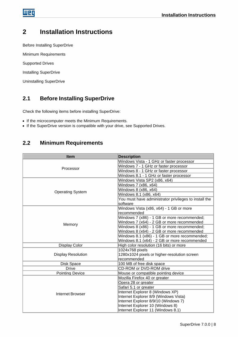
2.2 Minimum Requirements
Item Description
Processor
Windows Vista - 1 GHz or faster processorWindows 7 - 1 GHz or faster processorWindows 8 - 1 GHz or faster processorWindows 8.1 - 1 GHz or faster processor
Operating System
Windows Vista SP2 (x86, x64)Windows 7 (x86, x64)Windows 8 (x86, x64)Windows 8.1 (x86, x64)You must have administrator privileges to install thesoftware
Memory
Windows Vista (x86, x64) - 1 GB or morerecommendedWindows 7 (x86) - 1 GB or more recommended;Windows 7 (x64) - 2 GB or more recommendedWindows 8 (x86) - 1 GB or more recommended;Windows 8 (x64) - 2 GB or more recommendedWindows 8.1 (x86) - 1 GB or more recommended;Windows 8.1 (x64) - 2 GB or more recommended
Display Color High color resolution (16 bits) or more
Display Resolution1024x768 pixels1280x1024 pixels or higher-resolution screenrecommended
Disk Space 100 MB of free disk spaceDrive CD-ROM or DVD-ROM drive
Pointing Device Mouse or compatible pointing device
Internet Browser
Mozilla Firefox 40 or greaterOpera 28 or greaterSafari 5.1 or greaterInternet Explorer 8 (Windows XP)Internet Explorer 8/9 (Windows Vista)Internet Explorer 8/9/10 (Windows 7)Internet Explorer 10 (Windows 8)Internet Explorer 11 (Windows 8.1)
Installation Instructions
SuperDrive 7.0.0 | 9
Item DescriptionJavaScript enabledBrowser should support Cascading Style Sheets(CSS1) and JavaScript
Communication RS232 Serial Interface
(x86) = 32-bit Edition.(x64) = 64-bit Edition.
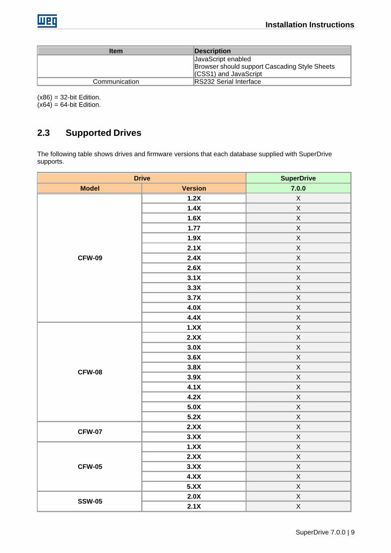
2.3 Supported Drives
The following table shows drives and firmware versions that each database supplied with SuperDrivesupports.
Drive SuperDrive
Model Version 7.0.0
CFW-09
1.2X X
1.4X X
1.6X X
1.77 X
1.9X X
2.1X X
2.4X X
2.6X X
3.1X X
3.3X X
3.7X X
4.0X X
4.4X X
CFW-08
1.XX X
2.XX X
3.0X X
3.6X X
3.8X X
3.9X X
4.1X X
4.2X X
5.0X X
5.2X X
CFW-072.XX X
3.XX X
CFW-05
1.XX X
2.XX X
3.XX X
4.XX X
5.XX X
SSW-052.0X X
2.1X X
Installation Instructions
SuperDrive 7.0.0 | 10
Drive SuperDrive
Model Version 7.0.0
2.2X X
2.3X X
SSW-04
2.XX X
3.XX X
4.XX X
5.XX X
5.2X X
5.3X X
5.4X X
SSW-03
2.XX X
3.XX X
4.XX X
5.XX X
5.1X X
5.2X X
5.3X X
5.4X X
SCA-05
2.1X X
2.2X X
2.4X X
2.7X X
SCA-04
1.XX X
2.XX X
3.XX X
4.XX
4.0X X
4.1X X
4.2X X
CTW-04
1.0X X
1.1X X
1.4X X
MVW-01
1.4X X
1.5X X
1.6X X
1.7X X
1.8X X
1.9X X
3.0X X
3.2X X
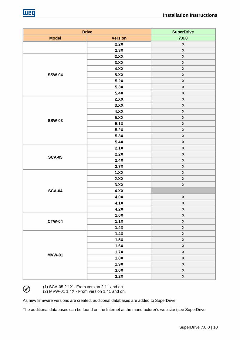
(1) SCA-05 2.1X - From version 2.11 and on.(2) MVW-01 1.4X - From version 1.41 and on.
As new firmware versions are created, additional databases are added to SuperDrive.
The additional databases can be found on the Internet at the manufacturer's web site (see SuperDrive

Installation Instructions
SuperDrive 7.0.0 | 11
7.0.0).
If your drive uses a special firmware version (customized version), SuperDrive needs an additionaldatabase. Request this additional database for the manufacturer.
The software allows communication only with the drive types listed in the above table.
Firmware is the software which controls the drive. To find out which is the firmware version, readparameter P0023.
Installation Instructions
SuperDrive 7.0.0 | 12
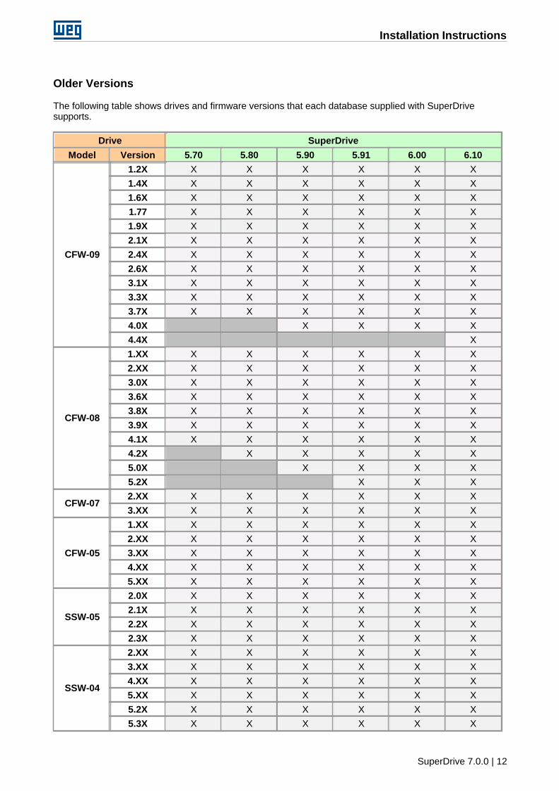
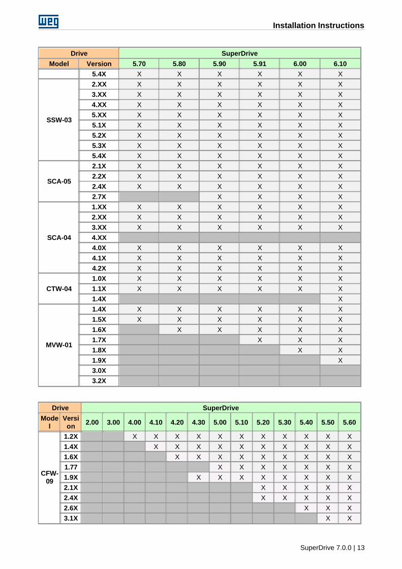
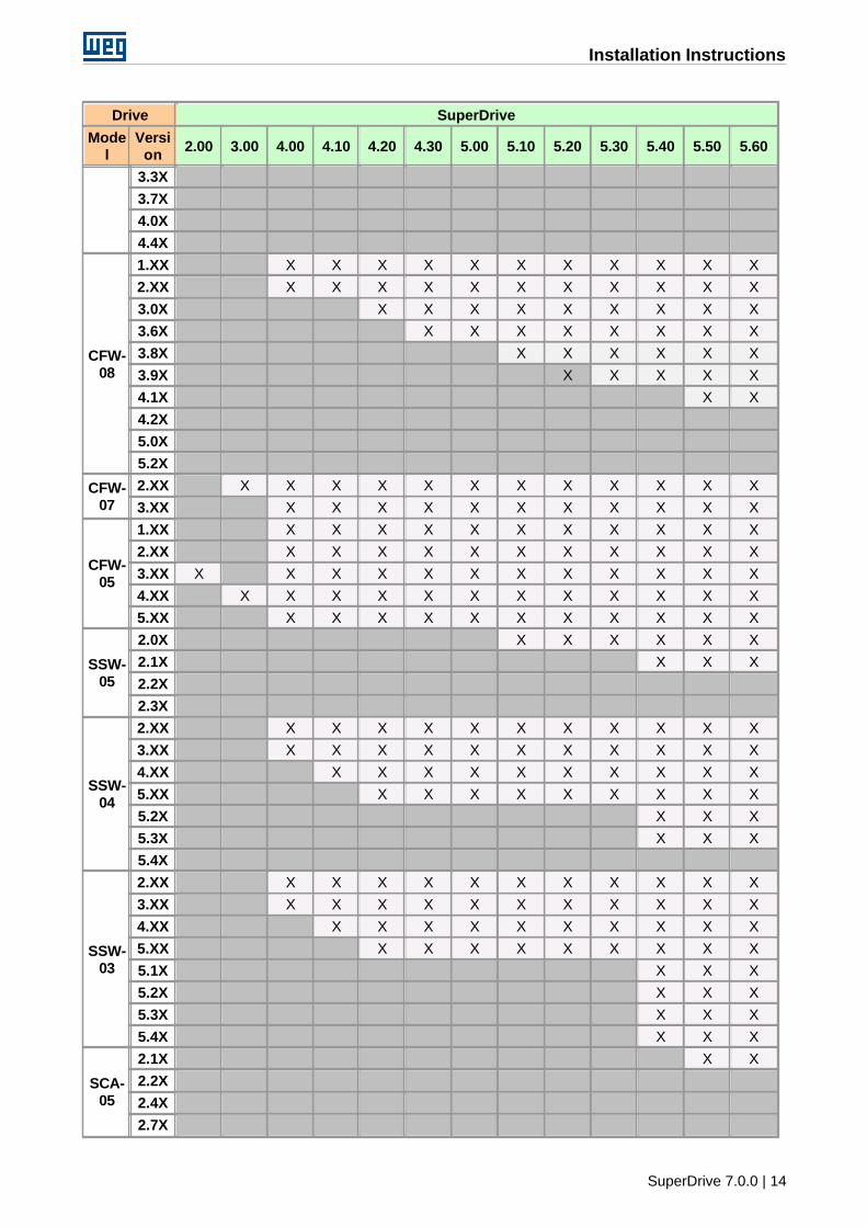
Older Versions
The following table shows drives and firmware versions that each database supplied with SuperDrivesupports.
Drive SuperDrive
Model Version 5.70 5.80 5.90 5.91 6.00 6.10
CFW-09
1.2X X X X X X X
1.4X X X X X X X
1.6X X X X X X X
1.77 X X X X X X
1.9X X X X X X X
2.1X X X X X X X
2.4X X X X X X X
2.6X X X X X X X
3.1X X X X X X X
3.3X X X X X X X
3.7X X X X X X X
4.0X X X X X
4.4X X
CFW-08
1.XX X X X X X X
2.XX X X X X X X
3.0X X X X X X X
3.6X X X X X X X
3.8X X X X X X X
3.9X X X X X X X
4.1X X X X X X X
4.2X X X X X X
5.0X X X X X
5.2X X X X
CFW-072.XX X X X X X X
3.XX X X X X X X
CFW-05
1.XX X X X X X X
2.XX X X X X X X
3.XX X X X X X X
4.XX X X X X X X
5.XX X X X X X X
SSW-05
2.0X X X X X X X
2.1X X X X X X X
2.2X X X X X X X
2.3X X X X X X X
SSW-04
2.XX X X X X X X
3.XX X X X X X X
4.XX X X X X X X
5.XX X X X X X X
5.2X X X X X X X
5.3X X X X X X X
Installation Instructions
SuperDrive 7.0.0 | 13
Drive SuperDrive
Model Version 5.70 5.80 5.90 5.91 6.00 6.10
5.4X X X X X X X
SSW-03
2.XX X X X X X X
3.XX X X X X X X
4.XX X X X X X X
5.XX X X X X X X
5.1X X X X X X X
5.2X X X X X X X
5.3X X X X X X X
5.4X X X X X X X
SCA-05
2.1X X X X X X X
2.2X X X X X X X
2.4X X X X X X X
2.7X X X X X
SCA-04
1.XX X X X X X X
2.XX X X X X X X
3.XX X X X X X X
4.XX
4.0X X X X X X X
4.1X X X X X X X
4.2X X X X X X X
CTW-04
1.0X X X X X X X
1.1X X X X X X X
1.4X X
MVW-01
1.4X X X X X X X
1.5X X X X X X X
1.6X X X X X X
1.7X X X X
1.8X X X
1.9X X
3.0X
3.2X
Drive SuperDrive
Model
Version
2.00 3.00 4.00 4.10 4.20 4.30 5.00 5.10 5.20 5.30 5.40 5.50 5.60
CFW-09
1.2X X X X X X X X X X X X
1.4X X X X X X X X X X X
1.6X X X X X X X X X X
1.77 X X X X X X X
1.9X X X X X X X X X
2.1X X X X X X
2.4X X X X X X
2.6X X X X
3.1X X X
Installation Instructions
SuperDrive 7.0.0 | 14
Drive SuperDrive
Model
Version
2.00 3.00 4.00 4.10 4.20 4.30 5.00 5.10 5.20 5.30 5.40 5.50 5.60
3.3X
3.7X
4.0X
4.4X
CFW-08
1.XX X X X X X X X X X X X
2.XX X X X X X X X X X X X
3.0X X X X X X X X X X
3.6X X X X X X X X X
3.8X X X X X X X
3.9X X X X X X
4.1X X X
4.2X
5.0X
5.2X
CFW-07
2.XX X X X X X X X X X X X X
3.XX X X X X X X X X X X X
CFW-05
1.XX X X X X X X X X X X X
2.XX X X X X X X X X X X X
3.XX X X X X X X X X X X X X
4.XX X X X X X X X X X X X X
5.XX X X X X X X X X X X X
SSW-05
2.0X X X X X X X
2.1X X X X
2.2X
2.3X
SSW-04
2.XX X X X X X X X X X X X
3.XX X X X X X X X X X X X
4.XX X X X X X X X X X X
5.XX X X X X X X X X X
5.2X X X X
5.3X X X X
5.4X
SSW-03
2.XX X X X X X X X X X X X
3.XX X X X X X X X X X X X
4.XX X X X X X X X X X X
5.XX X X X X X X X X X
5.1X X X X
5.2X X X X
5.3X X X X
5.4X X X X
SCA-05
2.1X X X
2.2X
2.4X
2.7X
Installation Instructions
SuperDrive 7.0.0 | 15
Drive SuperDrive
Model
Version
2.00 3.00 4.00 4.10 4.20 4.30 5.00 5.10 5.20 5.30 5.40 5.50 5.60
SCA-04
1.XX X X X X X X X X X X X
2.XX X X X X X X X X X X X
3.XX X X X X X X X X X X X
4.XX X X X X X X X X X
4.0X
4.1X
4.2X X X X X X
CTW-04
1.0X X X X X
1.1X X X X X
1.4X
MVW-01
1.4X
1.5X
1.6X
1.7X
1.8X
1.9X
3.0X
3.2X
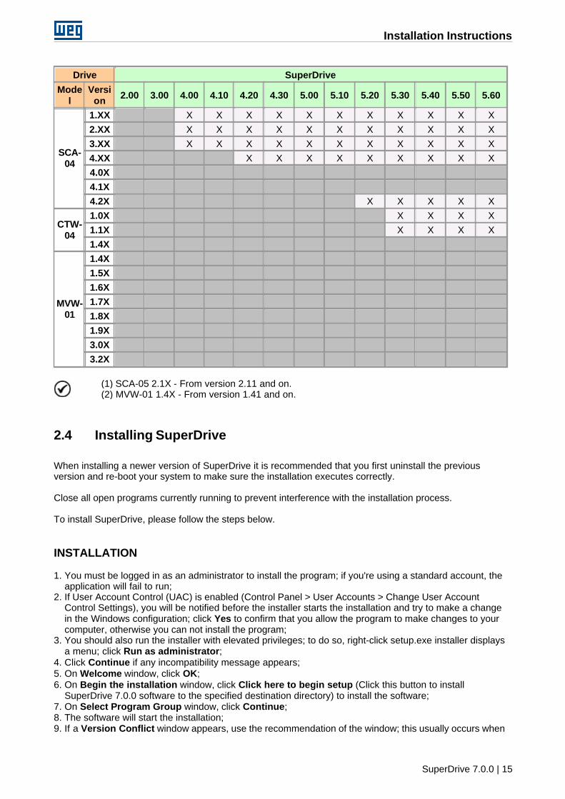
(1) SCA-05 2.1X - From version 2.11 and on.(2) MVW-01 1.4X - From version 1.41 and on.
2.4 Installing SuperDrive
When installing a newer version of SuperDrive it is recommended that you first uninstall the previousversion and re-boot your system to make sure the installation executes correctly.
Close all open programs currently running to prevent interference with the installation process.
To install SuperDrive, please follow the steps below.
INSTALLATION
1. You must be logged in as an administrator to install the program; if you're using a standard account, theapplication will fail to run;
2. If User Account Control (UAC) is enabled (Control Panel > User Accounts > Change User AccountControl Settings), you will be notified before the installer starts the installation and try to make a changein the Windows configuration; click Yes to confirm that you allow the program to make changes to yourcomputer, otherwise you can not install the program;
3. You should also run the installer with elevated privileges; to do so, right-click setup.exe installer displaysa menu; click Run as administrator;
4. Click Continue if any incompatibility message appears;5. On Welcome window, click OK;6. On Begin the installation window, click Click here to begin setup (Click this button to install
SuperDrive 7.0.0 software to the specified destination directory) to install the software;7. On Select Program Group window, click Continue;8. The software will start the installation;9. If a Version Conflict window appears, use the recommendation of the window; this usually occurs when
Installation Instructions
SuperDrive 7.0.0 | 16
the file to be installed is older than the current file in the system; click Yes to keep the current file in thesystem;
10.On the last window where the message "SuperDrive 7.0.0 Setup was completed successfully" appears,click OK to exit.
2.5 Uninstalling SuperDrive
To uninstall SuperDrive, please follow the steps below.
UNINSTALLATION
As indicated below, use Programs and Features utility from control panel to remove SuperDrive. Donot manually delete files and folders.
1. In Control Panel, click Programs and Features > SuperDrive 7.0.0 > Uninstall;2. You must be logged in as an administrator to remove the program; if you're using a standard account,
then you can not remove the software;3. If User Account Control (UAC) is enabled (Control Panel > User Accounts > Change User Account
Control Settings), you will be notified before starting the removal and try to make a change in theWindows configuration; click Yes to confirm that you allow the program to make changes to yourcomputer, otherwise you can not remove the program;
4. On Application Removal window, click Yes to confirm you want to remove the program;5. On Shared Component window (if it appears), select the best option for the question; normally select
Remove if you are sure the file is not used by other programs, otherwise press Keep;6. In the last window where the message "Program installation removed" appears, click OK to exit.
SuperDrive Structure
SuperDrive 7.0.0 | 17
3 SuperDrive Structure
SuperDrive Architecture
Project Architecture
3.1 SuperDrive Architecture
The SuperDrive is divided in directories and several files are part of the system.
SUPERDRIVE PATH
The SuperDrive is installed in one directory of the hard disk called as ...\SuperDrive 7.0.0.
DIRECTORY ...\SuperDrive 7.0.0
SuperDrive.exeMain File of the SuperDrive
Chart.dllCommunicate.dllCopy.dllData.dllDocument.dllHMI.dllIPowerup.dllProgressBar.dllSDComm.dllSelfTuning.dllTools.dllUpdate.dllVectorControl.dllLibraries used by the SuperDrive.
DIRECTORY ...\SuperDrive 7.0.0\Drivers
*P.wcdDevice driver in Portuguese of the drive
*E.wcdDevice driver in English of the drive
*S.wcdDevice driver in Spanish of the drive
*.def, *.verDefinition files of SuperDrive.
DIRECTORY ...\SuperDrive 7.0.0\Graphics
*.icoIcon files.
*.bmp

SuperDrive Structure
SuperDrive 7.0.0 | 18
Bitmap files.
*.jpgJpg files.
*.curCursor files.
DIRECTORY...\SuperDrive 7.0.0\Help
*.chmSuperDrive Help Files.
DIRECTORY ...\SuperDrive 7.0.0\Media
*.wavSound files.
3.2 Project Architecture
The project consists in a directory and a set of files.
PROJECT ARCHITECTURE
Each project is stored in the directory ...\SuperDrive 7.0.0\Projects\XXXXXXXX where XXXXXXXX is thename of the project.All files are stored in this directory.
FILES
Each project is divided into several files in the project directory. The files are described below.
Project.sdpMain project file.
XX.parFile with the content of the drive parameters in the address XX (01...30)
XX.rerFile with the occurred errors during drive read operation.
XX.werFile with the occurred errors during drive write operation.
Application.appFile with the application data.
Customer.appFile with the customer data.
EndUser.appFile with the EndUser data.
XX.sdpFile with the drive data.
XX.mot
SuperDrive Structure
SuperDrive 7.0.0 | 19
File with the motor data.
*.chtFile with the adquired points from drive.
XX.hmiFile with parameters stored in the EEPROM memory of the keypad.
*.gol*File with the adquired points from drive.
*.trc*File with the data stored by the Trace function, acquired from drive.
*.errFile with the register of errors stored in the drive.
Menus
SuperDrive 7.0.0 | 20
4 Menus
Project
NewOpenCloseSave asRemovePrint SetupPrintExit
View
ToolBarDriveBarStatusBar
Offline
ParametersApplication DataCustomer DataEnd User DataDrive DataMotor Data
Online
Select Drive AddressRead Parameters (Drive -> PC)Write Parameters (PC -> Drive)Monitor ParametersMonitor Using KeypadMonitor Parameters using ModemAcquire ParameterView ChartOnline GraphTrace FunctionError LogIdentify DrivesCommunication Settings
Macros
Basic ApplicationAlways Local CommandAlways Remote CommandMultispeed with Commands via Digital InputsLocal/Remote Command with Selection via HMILocal Command with Reference via HMI and 3-Wire Start/Stop
Tools
Drives NetworkUpdate parameters to other firmware versionLanguageOptions
Help
Menus
SuperDrive 7.0.0 | 21
TopicsAbout SuperDrive
4.1 Project
New
Open
Close
Save as
Remove
Print Setup
Exit
4.1.1 New
ACCESS
Menu: Project + NewShortcut Key: Ctrl+N
FUNCTION
It creates a new project.
DESCRIPTION
Enter the name of the new project. If the selected name is valid, the project will be open after confirmed bythe Ok button.The cancel button does not created the project and closes the dialogue.
4.1.2 Open
ACCESS
Menu: Project + OpenShortcut Key: Ctrl+O
FUNCTION
Opens an existing project.
Menus
SuperDrive 7.0.0 | 22
DESCRIPTION
Select one of the existing projects from the project list and press Ok button or press with the left button ofthe mouse two times on the selected project.The project will be opened automatically and the drive network window shows the drives that areconfigured in the project.
4.1.3 Close
ACCESS
Menu: Project + CloseShortcut Key: -
FUNCTION
Closes the current project.
DESCRIPTION
When a project is closed, some menu items are disabled and thus those functions can not be accessed.
4.1.4 Save As
ACCESS
Menu: Project + Save asShortcut Key: -
FUNCTION
Saves the actual current project with other name.
DESCRIPTION
Enter the new name of the current project. Is the chosen name valid, the project will be open afterconfirmation by Ok button. The Cancel button does not save the project and closes the dialogue.
4.1.5 Remove
ACCESS
Menu: Project + RemoveShortcut Key: -
FUNCTION
Removes the selected project.
Menus
SuperDrive 7.0.0 | 23
DESCRIPTION
Select a project from the list of existing projects and press OK button. The user has to confirm projectdeletion before it is completely removed. OK button is disabled while no project is selected. Any projectcan be removed, including the active project (the one that is opened).
4.1.6 Print Setup
ACCESS
Menu: Project + Print SetupShortcut Key: -
FUNCTION
It changes the printer and the printing options.
DESCRIPTION
It permits the printer selection, changing the printing quality, paper, etc.It shows the standard dialogue box of the printing configuration with options to specify the printer, paperorientation, paper size and paper source, as well as other printing options.
4.1.7 Print
ACCESS
Menu: Project + PrintShortcut Key: Ctrl+P
FUNCTION
Prints the project data.
DESCRIPTION
It prints the following project data:· Application Data· Customer Data· End User Data· Drive Data· Motor Data· Parameters
Menus
SuperDrive 7.0.0 | 24
4.1.8 Exit
ACCESS
Menu: Project + ExitShortcut Key: -
FUNCTION
Closes the open project and quits the SuperDrive.
DESCRIPTION
All information and configuration are stored automatically.
4.2 View
ToolBar
DriveBar
StatusBar
4.2.1 ToolBar
ACCESS
Menu: Display + toolbarShortcut Key: -
FUNCTION
Shows and hides Toolbar.
DESCRIPTION
The Toolbar contains the icons corresponding to the menu items.
4.2.2 DriveBar
ACCESS
Menu: Display + DriveBarShortcut Key: -
FUNCTION
Menus
SuperDrive 7.0.0 | 25
Shows or hides the drivebar.
DESCRIPTION
The drivebar contains the information about the selected drive: tag, address, type, firmware version, ratedvoltage, rated current and serial port.
4.2.3 StatusBar
ACCESS
Menu: display + Status barShortcut Key: -
FUNCTION
Displays or hides the status bar.
DESCRIPTION
The status bar contains a field for system messages, status of the keys caps lock, num lock, insert andscroll lock, date and clock time.
4.3 Offline
Parameters
Application Data
Customer Data
End User Data
Drive Data
Motor Data
4.3.1 Parameters
ACCESS
Menu: Offline + ParametersShortcut Key: -
FUNCTION
Permits offline editing of the parameter content.
DESCRIPTION
Menus
SuperDrive 7.0.0 | 26
The online editing consists in displaying/changing of the parameter content.The parameters will be displayed sequentially on a grade in ascending order. There are 2 arrows forvertical scroll that permits to scroll the window up and down.Columns form the grade that contains a note, parameter number, function, Adjustable Range, FactorySetting, User's Setting and Unit.The only field that can be changed on the grade is the User's Setting.Some parameters can not be changed, but only displayed (reading parameters)
Displaying
The user's setting field is updated automatically after user has made changes.
Changes
The user must click on the User's Setting field and fill in this field the desired value. After that he mustpress Enter or click on Ok button.
The value inserted in the grade by the user is not checked in this stage. Only when the usertransfers the parameter content by using the function write to the drive, and when the parametervalue is out of range, i.e., when the value is not numerical, etc., the user will be informed about thisautomatically when the writing process is finished.
Commands
Show/Hide - This command shows or hides the secondary parameter lines on the grid.Print - printing of the chart with all information contained in the window.Export - export parameters to Microsoft Excel.Ok - when this command is give, you exit the window.Help - this command opens a Help window.
4.3.2 Application Data
ACCESS
Menu: Offline + Application dataShortcut Key: -
FUNCTION
It permits displaying/changing application data.
DESCRIPTION
Following data can be stored: title, version, data, description and comments.
4.3.3 Customer Data
ACCESS
Menu: Offline + Customer DataShortcut Key: -
FUNCTION
Menus
SuperDrive 7.0.0 | 27
Permits displaying/changing of customer data.
DESCRIPTION
Following data can be stored: company data (company address, city, state, Zip Code, country and homepage) and data for contacts (name, function, department, telephone, mobile phone, fax, bip and e-mail).
4.3.4 End User Data
ACCESS
Menu: Offline + End User DataShortcut Key: -
FUNCTION
Permits displaying/changing the end user data.
DESCRIPTION
Following data can be stored: company data (company address, city, state, Zip Code, country and homepage) and data for contacts (name, function, department, telephone, mobile phone, fax, bip and e-mail).
4.3.5 Drive Data
ACCESS
Menu: Offline + Drive DataShortcut Key: -
FUNCTION
Permits displaying/changing of the drive data.
DESCRIPTION
The following data can be stored: address, type, firmware version, rated voltage, rated current, tag,commercial reference and serial number.
Update Button: SuperDrive requests some basic data about the drive, such as type, firmware version, ratedvoltage, rated current. If no drive is detected at the address, then the fields will be erased automaticallyand all files related to this address will be deleted.
4.3.6 Motor Data
ACCESS
Menu: Offline + Motor DataShortcut Key: -
Menus
SuperDrive 7.0.0 | 28
FUNCTION
It permits displaying/changing the motor data.
DESCRIPTION
The following data can be stored: manufacturer, type, power, rpm, number of poles, rated voltage, ratedcurrent and serial number.
4.4 Online
Select Drive Address
Read Parameters (Drive -> PC)
Write Parameters (PC -> Drive)
Monitor Parameters
Monitor Using Keypad
Monitor Parameters using Modem
Acquire Parameter
View Chart
Online Graph
Trace Function
Error Log
Identify Drives
Communication Settings
4.4.1 Select Drive Address
ACCESS
Menu: Online + Select Drive AddressShortcut Key: -
FUNCTION
Selects one of the drive configured in the project.
DESCRIPTION
The configured drive is indicated by the check mark at the left of the selected menu item.
Menus
SuperDrive 7.0.0 | 29
4.4.2 Read Parameters (Drive -> PC)
ACCESS
Menu: Online + Read Parameters (Drive -> PC)Shortcut Key: -
FUNCTION
Transfers the content of each drive parameter to the microcomputer.
DESCRIPTION
Also known as download, the user can visualize the advance of the parameter reading.Errors that occurred during the reading will be displayed and the end of the reading.
4.4.3 Write Parameters (PC -> Drive)
ACCESS
Menu: Online + Write Parameters (PC -> Drive)Shortcut Key: -
FUNCTION
Transfer the content of each parameter stored on the PC (Source Drive) to the Destination Drive.The file XX.par with the parameter contents is required, otherwise an error message will be displayed.
DESCRIPTION
Known as upload, the user can visualize the advance of the parameter writing.Errors that occurred during the writing will be displayed and the end o the writing process.The user shall select the destination address.Model, firmware version, and tag of the source drive are automatically presented.
It will be necessary to confirm if SuperDrive must change the configuration of the destination drive on theproject when transferring parameters to a drive with a different address from the source drive. Theinformation of the connected drive will be stored on the project. However, in case there is already a driveconfigured in that address, the configurations of the connected drive will substitute the configurations of thedrive that was previous stored on the project.
It is recommended to write the parameters to drives of the same model and firmware version.
Example:
Source: Address 02, CFW-09 model, firmware version V4.00Destination: Address 12, CFW-09 model, firmware version V4.00
It is possible to write parameters to different firmware versions in case the drive is from the CFW-09 series.In order to do that it is necessary to update the parameters to the version of the destination drive.Currently, the following versions have the automatic updating function: v2.4x, v2.6x, v3.1x, v3.7x and
Menus
SuperDrive 7.0.0 | 30
v4.0x. Any update between these versions can be automatically performed. Versions that were notmentioned above can be manually updated by using this tool.
4.4.4 Monitor Parameters
ACCESS
Menu: Online + Monitor ParametersShortcut Key: -
FUNCTION
It permits online editing of all drive parameters contents.
DESCRIPTION
The online editing consists in showing/changing all parameter contents.The parameters are showed sequentially on a grid in ascending order. There are two arrows for scrollingdown/up. The grid comprises columns containing a note, the parameter number, function range, factorysetting, user‘s setting, unit and comparison. The only field that can be changed in the grid is the user'ssetting.
Visualization
The user‘s field is updated automatically.
Changing
The user must click on the user‘s setting field and fill in the filed the desired value. Then he must activeEnter and click on OK.
Commands
Show/Hide - This command shows or hides the secondary parameter lines on the grid.Ok - when this command is give, you exit the window.Help - this command opens a Help window.
4.4.5 Monitor Using Keypad
ACCESS
Menu: Online + Monitor Using KeypadShortcut Key: -
FUNCTION
This function allows to show/change the drive parameter in a similar way as the drive keypad.
DESCRIPTION
CFW and MVW Line
Menus
SuperDrive 7.0.0 | 31
The keypad (HMI) is a simple interface that allows the inverter operation/programming.This interface allows permits following functions:· indication of the operation status, as well as the display of the main variables.· fault display.· visualization and changing of the settable parameters.· operation: enable, disable, reversal, jog, commutation: local/remote, incrementing/decrementing the
parameter number, general enable, general disable, serial reference.· virtual keypad - local: the key Enable allows that all commands can be executed via serial interface in
local status, the key Disable allows that all commands can be executed via serial interface (HMI) in localstatus.
· virtual key - remote: the key Enable allows that all commands can be executed via serial interface inremote status, the key Disable allows that all commands can be executed via serial interface (HMI) inremote status.
Line SSW
The keypad (HMI) is a simple interface that allows the soft-starter operation/programming.This interface allows permits following functions:· indication of the operation status, as well as the display of the main variables.· fault display.· visualization and changing of the settable parameters.· operation: enable, disable, reversal, jog, incrementing/decrementing the parameter number, general
enable, general disable.· Motor status: acceleration. Current limiting, rated voltage, energy saving, deceleration, braking, reversal
and power supply.
Line SCA
The keypad (HMI) is a simple interface that allows the servodrive operation/programming.This interface allows permits following functions:· indication of the operation status, as well as the display of the main variables.· fault display.· display and change of the settable parameters.· Operation: enable, speed reference, current reference or position reference, STOP function, among
others.
4.4.6 Monitor Parameters using Modem
ACCESS
Menu: Online + Monitor Parameters using ModemShortcut Key: -
FUNCTION
Its allow you to monitor the parameters using a telephone line.
DESCRIPTION
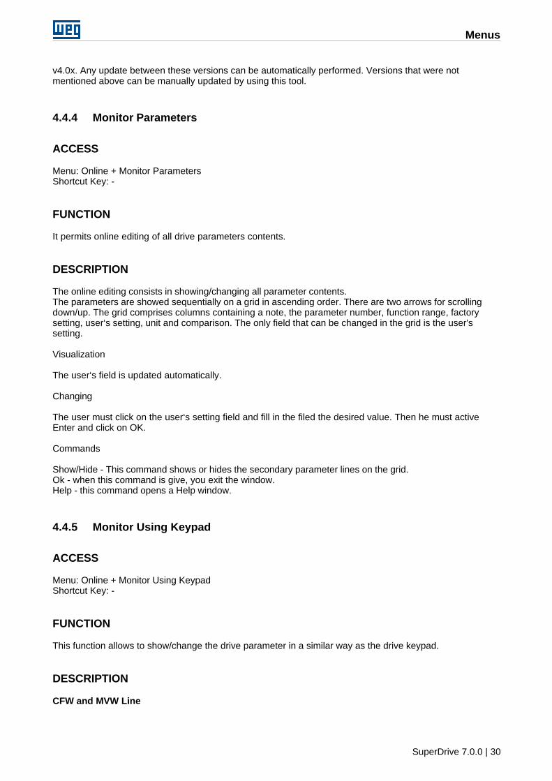
It is possible to remotely monitor a drive by using the phone line. In one side we have SuperDriveconnected to a modem (internal or external). On the other side of the phone line we have another modemwith auto-answer feature, which is connected to a drive. SuperDrive dials the modem with auto-answerfeature, the modems establish the communication with each other, and then it is possible to monitor thedrive. Figure below illustrates the application.
Menus
SuperDrive 7.0.0 | 32
(1) PC with SuperDrive Software.(2) Internal or external Modem.(3) External modem with auto-answer feature.(4) Drive.(5) Direct Modem cable (pin-to-pin) when modem is external.(6) Telephone Line.(7) Modem Null Cable (crossover cable).(8) RS232 PC/Drive serial cable (SuperDrive standard cable).
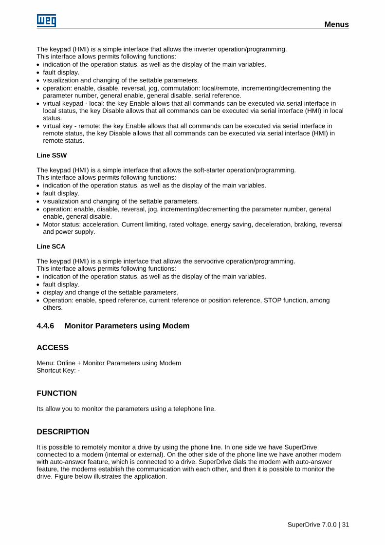
Direct Modem Cable (pin-to-pin) when using external modem.
This pin-to-pin cable is used to connect the microcomputer to the modem and perform the dialing. Thispin-to-pin characteristic means that the same signal from one cable end must be connected to the othercable end.
Example 1: in case of using a cable with two DB9 connectors, pin 1 of the connector will be connected tothe pin 1 of the other connector, pin 2 connected to pin 2, and so on.Example 2: when a DB25 connector cable is connected to a DB9 connector, the pin 8 of the connectorDB25 must be connected to the pin 1 of the DB9 connector, and pin 3 of the connector DB25 must beconnected to pin 2 of the connector DB9 and so forth.
Table below shows the pin location of this cable.
Modem PCSignal name DB25 DB9 DB9 DB25 Signal nameCD (Carrier
Detect)8 1 1 8 CD
RD (ReceiveData)
3 2 2 3 RD
TD (TransmitData)
2 3 3 2 TD
DTR (DataTerminal Ready)
20 4 4 20 DTR
SG (SignalGround)
7 5 5 7 SG
DSR (Data SetReady)
6 6 6 6 DSR
RTS (Request ToSend)
4 7 7 4 RTS
CTS (Clear ToSend)
5 8 8 5 CTS
RI (RingIndicator)
22 9 9 22 RI
FG (FrameGround)
1 - - 1 FG
Drive/PC RS232 serial cable (SuperDrive Standard Cable)
Menus
SuperDrive 7.0.0 | 33
Drive/PC RS232 serial Cable is the standard cable.
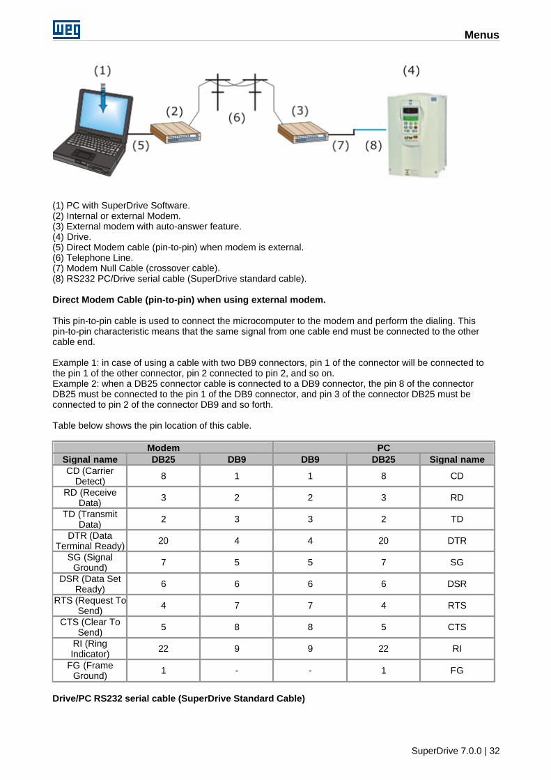
Null Modem Cable (Crossover Cable)
The cable used to connect the modem to the SuperDrive standard cable is named as null modem orcrossover cable.
The Null Modem cable allows two DTE RS232 devices to communicate with each other. In order to do that,the TD signal from one device shall be connected to the RD input of the other device (and vice versa).
The following table indicates the pins connection when using a null modem cable.
Connector Side A Connector Side BSignal name DB25 DB9 DB9 DB25 Signal nameFG (Frame
Ground)1 - - 1 FG
TD (TransmitData)
2 3 2 3 RD
RD (ReceiveData)
3 2 3 2 TD
RTS (Request ToSend)
4 7 8 5 CTS
CTS (Clear ToSend)
5 8 7 4 RTS
SG (SignalGround)
7 5 5 7 SG
DSR (Data SetReady)
6 6 4 20 DTR
CD (CarrierDetect)
8 1 4 20 DTR
DTR (DataTerminal Ready)
20 4 1 8 CD
DTR (DataTerminal Ready)
20 4 6 6 DSR
For this application only signals RD, TD and GND are used..
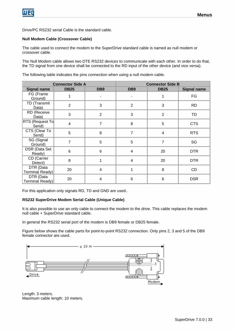
RS232 SuperDrive Modem Serial Cable (Unique Cable)
It is also possible to use an only cable to connect the modem to the drive. This cable replaces the modemnull cable + SuperDrive standard cable.
In general the RS232 serial port of the modem is DB9 female or DB25 female.
Figure below shows the cable parts for point-to-point RS232 connection. Only pins 2, 3 and 5 of the DB9female connector are used.
Length: 3 meters.Maximum cable length: 10 meters.
Menus
SuperDrive 7.0.0 | 34
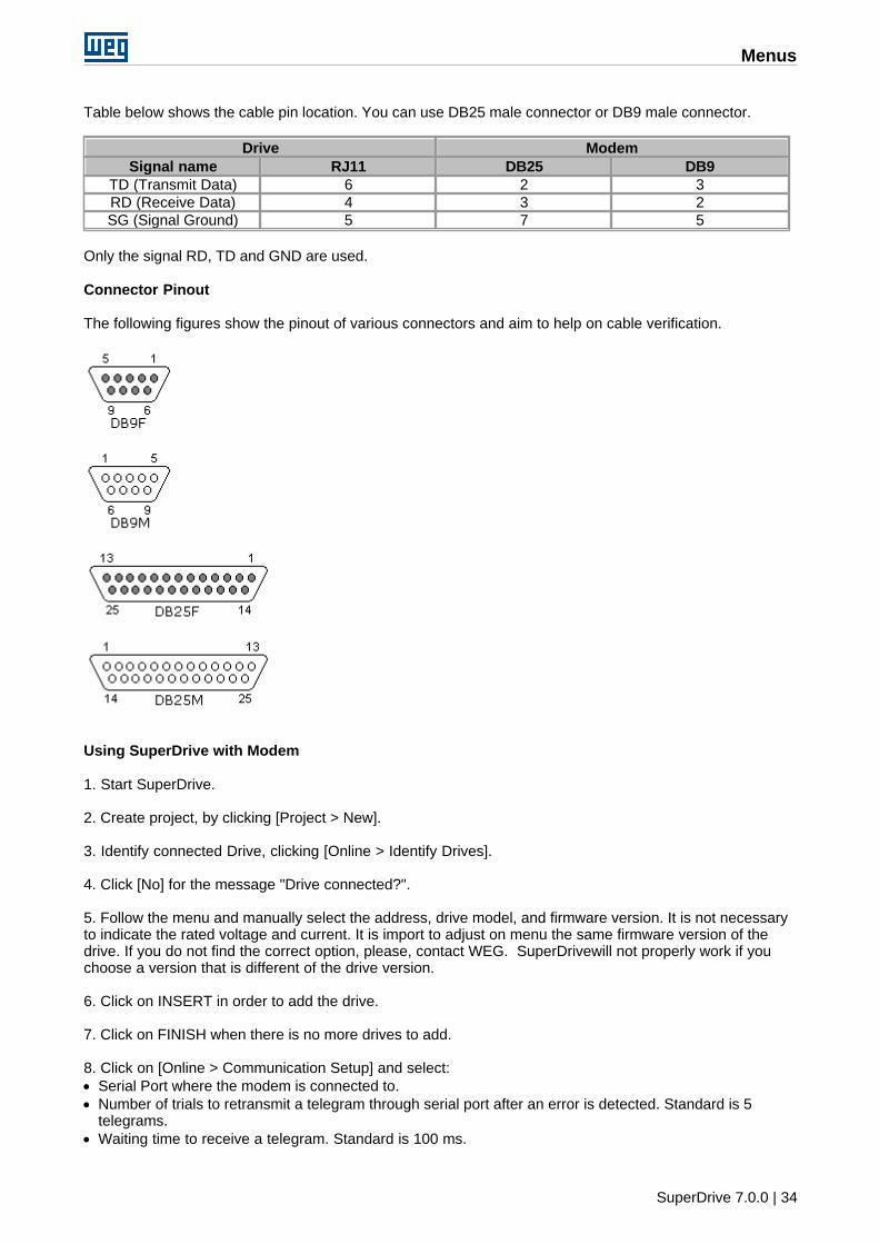
Table below shows the cable pin location. You can use DB25 male connector or DB9 male connector.
Drive ModemSignal name RJ11 DB25 DB9
TD (Transmit Data) 6 2 3RD (Receive Data) 4 3 2SG (Signal Ground) 5 7 5
Only the signal RD, TD and GND are used.
Connector Pinout
The following figures show the pinout of various connectors and aim to help on cable verification.
Using SuperDrive with Modem
1. Start SuperDrive.
2. Create project, by clicking [Project > New].
3. Identify connected Drive, clicking [Online > Identify Drives].
4. Click [No] for the message "Drive connected?".
5. Follow the menu and manually select the address, drive model, and firmware version. It is not necessaryto indicate the rated voltage and current. It is import to adjust on menu the same firmware version of thedrive. If you do not find the correct option, please, contact WEG. SuperDrivewill not properly work if youchoose a version that is different of the drive version.
6. Click on INSERT in order to add the drive.
7. Click on FINISH when there is no more drives to add.
8. Click on [Online > Communication Setup] and select:· Serial Port where the modem is connected to.· Number of trials to retransmit a telegram through serial port after an error is detected. Standard is 5
telegrams.· Waiting time to receive a telegram. Standard is 100 ms.
Menus
SuperDrive 7.0.0 | 35
· Modem delay time. Standard is 5000 ms.
9. Click on [Online > Monitor Parameters using a Modem].
10. Under Modem window specify:· Modem command for dialing, the suggested standard is ATDT.· Phone Number (when using an extension line, add a comma in order to insert an one-second pause).· Example 1: Phone number 0,33724000. It is a local call.· Example 2: Phone number 0,0XX4733724000. It is a long distance call, where XX is the phone company
code and the area code is 47.
11. Click on [Dial] and wait for the CD signal (green color).
12. After the phone call is established, click on [Start monitoring].
13. SuperDrive is now monitoring the drive through the phone line.
For more details, see online help, accessing [Help > Topics].
Suggestions for Modems
ATMC - Automação e Comunicação Ltda.http://www.atmc.com.brModel MV34.
To display the commands, use the commands ATE1.E1 = Eco enabled, ecoa commands to the computer to display what is entered via keypad.
To operate the auto-answer, the manufacturer suggests to apply following commands:"AT&F&D0&T5X3&K0S2=128S0=2".AT informs the modem that an AT command is coming.&F loads factory setting.&D0 ignores DTR signal.&T5 disables the remote digital loop recognition.&X3 enables dialing without tone recognition.&K0 disables the local flow control.&S2=128 ignores escape sequence.&S0=2 answers after 2nd ringing (auto answer).
The user must save the configuration in NVRAM by using "AT&W&W1".&W saves active profile in profile 0.&W1 saves active profile in profile 1.
To display what has being saved, enter "AT&V".&V shows the current configuration and the saved profile.
To implement these commands correctly, check the modem manual or contact the ATMC TechnicalSupport.
Jumpers of the Modem MV34:S1 = 2-3S2 = -S3 = 2-3
Encore Electronics Inc.http://www.encore-usa.com/product.php?id=30Model ENF656-EV-CIPR external modem.
To display the commands, use the commands ATE1.E1 = Eco enabled, ecoa commands to the computer to display what is entered via keypad.
To operate the auto-answer, the manufacturer suggests to apply following commands:
Menus
SuperDrive 7.0.0 | 36
"AT&F&D0X3&K0S2=128S0=2".AT informs the modem that an AT command is coming.&F loads factory setting.&D0 ignores DTR signal.&X3 enables dialing without tone recognition.&K0 disables the local flow control.&S2=128 ignores escape sequence.&S0=2 answers after 2nd ringing (auto answer).
The user must save the configuration in NVRAM by using "AT&W&W1".&W saves active profile in profile 0.&W1 saves active profile in profile 1.
To display what has being saved, enter "AT&V".&V shows the current configuration and the saved profile.
To implement these commands correctly, check the modem manual or contact the ATMC TechnicalSupport.
How to install a standard modem on Windows
· Go to the Start Menu/ Configuration / Control Panel -> Modem and telephone options -> Modems.· Press the button Add.· Select: "Do not detect the modem. It will be selected from a list" and press Next.· Select "(standard Modem types)" and "33600 bps standard Modem" and press Next. Obs.: in the model
section the model must be selected according to modem manufacturer specification.· Select the serial port where the modem will be connected and press Next. Obs.: This information will be
necessary to configure the serial communication of the SuperDrive when on the Online menu theMonitoring using modem option is used.
· Press Finish.· The modem has been created and it appears on the Modem and telephone Options· It is possible to visualize the properties of the modem by clicking on the Properties button.
4.4.7 Acquire Parameter
ACCESS
Menu: Online + Acquire ParameterShortcut Key: -
FUNCTION
It allows to acquire up to 4 parameters at the same time.
DESCRIPTION
File Name: file name where the acquired points will be saved.Example: P9 (full path will be showed on the window)
Drive Address: drive address in the network (01...30).
Parameters Number: number of parameters that will be monitored (01...04).
Parameters: number of each parameter which will be acquired.
Time between points: time between acquisitions.
Menus
SuperDrive 7.0.0 | 37
Milliseconds: range from 200...65535 msSeconds: range from 1...65 sHour:Minute:Second: range from 00:00:01...23:59:59
Number of Points: number of points to be acquired (read) from drive (1...2000000000)
Trigger Mode: there are 2 modes: manual or event.In manual mode the user must press the Start button to start the acquisitionIn event mode the acquisition is fired after the user has pressed the trigger button and the selected eventhas been fired.
Available Events
Inverter is enabled (RUN): the acquisition is started, after inverter has been enabled.
Inverter is READY to be enabled: the acquisition is started, when inverter is ready to be enabled.
Power supply voltage is too low for the inverter operation (Undervoltage): when the power supply voltage istoo low for the inverter operation, the acquisition is started.
P012 - DI1 = 0: when DI1 is inactive, the acquisition is started.
P012 - DI1 = 1: when DI1 is active, the acquisition is started.
P012 - DI2 = 0: when DI2 is inactive, the acquisition is started.
P012 - DI2 = 1: when DI2 is active, the acquisition is started.
P012 - DI3 = 0: when DI3is inactive, the acquisition is started.
P012 - DI3 = 1: when DI3 is active, the acquisition is started.
P012 - DI4 = 0: when DI4is inactive, the acquisition is started.
P012 - DI4 = 1: when DI4 is active, the acquisition is started.
P012 - DI5 = 0: when DI5is inactive, the acquisition is started.
P012 - DI5 = 1: when DI5 is active, the acquisition is started.
P012 - DI6 = 0: when DI6is inactive, the acquisition is started.
P012 - DI6 = 1: when DI6 is active, the acquisition is started.
P012 - DI7 = 0: when DI7 is inactive, the acquisition is started.
P012 - DI7 = 1: when DI7 is active, the acquisition is started.
P012 - DI8 = 0: when DI8 is inactive, the acquisition is started.
P012 - DI8 = 1: when DI8 is active, the acquisition is started.
P012 - DI9 = 0: when DI9 is inactive, the acquisition is started.
P012 - DI9 = 1: when DI9 is active, the acquisition is started.
P012 - DI10 = 0: when DI10 is inactive, the acquisition is started.
P012 - DI10 = 1: when DI10 is active, the acquisition is started.
<PXXX> > Content: when the content of the indicated parameter is greater than the selected one, theacquisition is started.
Menus
SuperDrive 7.0.0 | 38
<PXXX> < Content: when the content of the indicated parameter is less than the selected one, theacquisition is started.
<PXXX> = Content: when the content of the indicated parameter is equal to the selected one, theacquisition is started.
<PXXX> >= Content: when the content of the indicated parameter is greater then or equal to the selectedone, the acquisition is started.
<PXXX> <= Content: when the content of the indicated parameter is less than or equal to the selected one,the acquisition is started.
Parameter/Content: these fields are enabled only when one of the below events are selected.<PXXX> > Content<PXXX> < Content<PXXX> = Content<PXXX> >= Content<PXXX> <= Content
Start Data Acquisition Button: this command is used to start parameter acquisition when set to ManualMode.
Trigger Button: this command is used to trigger SuperDrive, i. e., SuperDrive monitors the selected eventuntil it occurs.
Erase Fields Button: it loads the standard values in the fields.
Ok Button: to exit the window.
Delay in the parameter acquisition with SuperDrive
There is always a delay between the parameter acquisition and the sampling time. If the sampling rate isset to a value greater than 1 second, the delay in the parameter acquisition is almost imperceptible.
Causes of delay:· Computer operational system is slow; too many programs running at the same time; number of
parameters and samples being acquired.· The timer that controls the sampling rate restarts the count when the processing routine ends; therefore,
all above delays are added to the acquisition time.
4.4.8 View Chart
ACCESS
Menu: Online + View ChartShortcut Key: -
FUNCTION
It permits to view the chart with up to 4 parameter that were acquired (Acquire Parameter function).
DESCRIPTION
User must select the name of the chart file (.cht extension).The chart is displayed in the window and it also indicates some information about the chart.This information is the same that has been entered by the user in the window Acquire Parameter, besides
Menus
SuperDrive 7.0.0 | 39
the start data, start hour, end data and end hour.
The following information will be available: · the scale of each parameter can be changed in the range from 1...32767.· function of each parameter.· chart type selection: bar 3D, bar 2D, line 3D, line 2D, area 3D, area 2D, step 3D, step 2D.· the user can enable/disable the grid , the marker or the line.· printing of the chart with all information contained in the window.· export graph data to Microsoft Excel.· definition of the number of visible points displayed on the graph (25 ... 2500).
4.4.9 Online Graph
ACCESS
Menu: Online + Online GraphShortcut Key: -
FUNCTION
This function allows monitoring (acquiring) up to 4 signals (parameters/variables) and visualizing thesesignals in a graph simultaneously.
DESCRIPTION
Signal SelectionThe user shall select the channels combo boxes to be used for the data acquisition, the drive address andthe signal (parameter/variable) to be monitored on the correspondent lists. By choosing the drive address,the drive model and the firmware version will be displayed, and the available signals will be loaded into thevariables list. By choosing the variable, the description and the minimum and maximum scale values willbe automatically loaded.
Setting the time between samplesThe time between samples can be set on the time between samples textbox. This is the time intervalbetween two consecutive signal samples.
Setting the time scaleChoose a horizontal scale for the graph from the list. This is the time interval presented on the graph.
Starting and stopping the acquisitionThe data acquisition can be started or stopped by pressing the Start/Stop button in the toolbar or byselecting the correspondent item under the Acquisition menu.
Pausing graph updatingIt is possible to stop the graph updating without interrupting the signal acquisition by pressing the Pausebutton or through the item Pause updating under the Graph menu.
Displaying the channel lineIt is possible to choose the channels to be shown on the graph by clicking on the channel check box belowthe horizontal axis scale. The other channels will be also acquired, however they will not be displayed onthe graph.
Signal ValueThe current signal value can be seen in the signal amplitude field. In the Cursor mode, when you click inany point of the graph, the signal value in that point is displayed.
Signal Scale
Menus
SuperDrive 7.0.0 | 40
The signal scale can be changed by using the Max and Min textboxes.
Changing the thickness and the color of the graph lineThe thickness and the color of the graph line for each signal can be changed.Click on the signal color (near the combo box) to change it. P.S.: this operation can be performed onlywhen the acquisition is stopped.Select one item from the list of line thicknesses (near the signal value) to change the line thickness.
Changing the graph background colorSelect the item Background Color under the submenu Color under the Graph menu to change the graphbackground color.
RecorderThere is an option for recording the data during the acquisition. After configuring the acquisition, press theRecord button or select the correspondent item under the Recorder menu. Start the acquisition. The datawill be saved in a file and the number of recorded points is presented in the status bar. Stop the acquisitionand save the file by using the option Save as of the Recorder menu.
Opening a file with stored dataSelect the item Open under the Graph menu and search for the file you want to display. It is possible tonavigate through the data by using the navigation bar below the graph.
ZoomPress the Zoom button or choose the correspondent item on the Graph menu to activate the Zoomfunction. Click on the graph and drag to select the portion of the graph you want to apply the zoom. Theselected area will be expanded to fit in the whole graph area.
Cursor modeClick on the Cursor button or select the correspondent item under the Graph menu to activate the cursormode. In this mode, when you click in any point of the graph, the time fot that point is presented in thegraph top and the signal values are presented in the signal amplitude textbox.P.S.: In this mode the zoom cannot be changed.
ExportIt is possible to export the acquisition file data to the Microsoft Excel format. Select the item Export underthe Graph menu to export the data.
Copy the graphSelect the item Copy to clipboard under the Graph menu to copy the graph to the clipboard. If the optionUse white background when printing or copying under the submenu Color is selected, then the graph will becopied with a white background instead of the colors that appear on the screen.
PrintSelect the Print item under Graph menu to print the current graph screen with the channel data, startingacquisition date, time scale and time between samples. If the option Use white background when printing orcopying under the submenu Color is selected, then the graph will be printed with a white backgroundinstead of the colors that appear on the screen.
Clear the graph screenSelect the item Clear under Graph menu to clear the graph screen.
MarkersSelect the item Markers under Graph menu to present the markers that identifies each graph channel.
4.4.10 Trace Function
ACCESS
Menu: Online + Trace FunctionShortcut Key: -
Menus
SuperDrive 7.0.0 | 41
FUNCTION
This function allows configuring the trace function and downloading the data stored on the drive's tracememory (these data can be displayed in a graph). This function is available only for the MVW-01 drive.
DESCRIPTION
SETTINGS
Reading ConfigurationsClick on the button Read Configuration to read the drive configuration. The parameters configuration of thedrive's trace function will be updated on the screen.
Writing ConfigurationsThe trace configurations will be sent to the drive when the Send Configuration button is pressed, however,the trace will not be activated.
Important: It is only possible to change the configuration if the data acquisition is inactive.
ChannelsThe channels from 1 to 8 can be configured by using the lists. The mask list is available only forparameters P012 and P013.
Sample TimeThe sample time shall be a multiple value of 500 microseconds.
Trigger ValueThe trigger value shall be configured with the internal representation of the processor so that the tracefunction works properly.Example: If P550 = 4, set P551 = 4095 to compare the value of P004 with the total DC Link voltage value(100%). The parameter P004 uses the numerical format Q4.12.
Data acquisition· The trace function is deactivated by pressing the Inactive button. P.S.: When the Inactive button is
pressed, the previous data stored on the drive is erased.· The trace configuration and the command to activate the trace function will be sent to the drive when the
Active button is pressed.
Acquiring the trace channels dataThe button Acquire trace points and the channel combo boxes will be enabled if the trace status is Tracecomplete.In order to acquire the trace channel data, first selected the desired channels, then change the filenamewhere the data should be saved (click on Change to change the filename) and finally press the Acquiretrace points button.It is possible to read data from other channels in different moments and save them in the same file.Press the Save as button to save the file with a different name. P.S.: the destination filename shall bedifferent from the source filename to avoid data lost.
ExportIt is possible to export the acquisition file data to the Microsoft Excel by pressing the Export button.
GRAPH
The trace information recorded in the file is presented in the left side. The SuperDrive indicates:· filename;· address, model, drive firmware version;· date and time of trigger;
Menus
SuperDrive 7.0.0 | 42
· number of points per channel;· trigger position;· parameters of the trace function.
Visualizing channels in the graphIt is possible to choose the channels to be displayed on the graph by clicking on the channel combo boxesbelow the horizontal axis scale.The parameters set in the trace channels are displayed below, where the user can change the scale ofeach channel by using the Max and Min textboxes, the line thickness and color for each channel, and seethe parameter value for the channel in the point where the cursor is located (when the Cursor mode isactive).
Horizontal axis scaleThe horizontal axis scale can be changed by selecting one of the available options. The Personalizedoption allows the user to select a different scale for the graph.
Opening a file with stored dataClick on the Open button under the Settings tab and search for the file you want to display. It is possible tonavigate through the data by using the navigation bar below the graph.
ZoomPress the Zoom button to activate this function. Click on the graph and drag to select the portion of thegraph you want to apply the zoom. The selected area will be expanded to fit in the whole graph area.
Cursor modeClick on the Cursor button to activate the cursor mode. In this mode, when you click in any graph point, theselected point is presented in the bottom part of the graph. The signal values are presented in the Cursortextbox.P.S.: In this mode the zoom cannot be changed.
PrintPress the Print button under the Settings tab to print the current graph screen with the channels data,trigger date, number of points per channel, and the trigger position.
4.4.11 Error Log
ACCESS
Menu: Online + Error LogShortcut Key: -
FUNCTION
This function allows visualizing the last 100 drive errors. Available only for the MVW-01 drive.
DESCRIPTION
With this function, it is possible to retrieve the last 100 errors stored on the drive and see them in a list.
In order to retrieve the errors press the Read Errors button. When the acquisition of the errors is complete,the data stored on the drive will be presented in a list. These data can be saved to a file by pressing theSave button.
In order to erase the data for the last errors in the screen press the clear button.
The options for exporting the data to Microsoft Excel and printing the errors list are available.
Menus
SuperDrive 7.0.0 | 43
4.4.12 Identify Drives
ACCESS
Menu: Online + Identify DrivesShortcut Key: -
FUNCTION
Identifies the drives that are RS232 network or via RS 484 connected. I.e. which drives can communicatewith the SuperDrive.
DESCRIPTION
It is possible to identify the drives automatically or selecting them manually.SuperDrive reads up to 30 drives that are RS485 network connected.
Automatic Detection
SuperDrive identifies automatically the drives that are network: at the end of the operation, the networkwindow shows the drives their characteristics.
Manual Selection
The manual selection is used when no drive is connected to the SuperDrive and is used only to create andoffline configuration.The user can insert 1 drive in RS232 and up to 30 drives in RS485.For each drive you must define at minimum the address, type and firmware version. The definition of therated voltage, rated current and tag are optional.
The drives have the following characteristics:
CFW-05, CFW-07, CFW-09, SSW-03, SSW-04, MVW-01:Address, type, firmware version, rated voltage, rated current.
CFW-08, SCA-04, SCA-05, SSW-05:Address, type, firmware version, rated current, rated current. (there is no rated voltage).
In manual selection, the firmware version defined by the user must be the same as that in the drive that willbe connected to the PC.
4.4.13 Communication Settings
ACCESS
Menu: Online + Communication SettingsShortcut Key: -
FUNCTION
Configures Serial Port.
Menus
SuperDrive 7.0.0 | 44
DESCRIPTION
Serial number of the port: 1...16 (COM1...COM16). It is the number of COM that will realize thecommunication between drive and SuperDrive.
Number of trials to transmit a telegram through serial port when an error is found: 1...10. This is thenumber of trials to send a telegram when the drive is not answering, i. e., the SuperDrive will send thetelegram how often the number of trials will be.
Time-out to receive a telegram (ms): it is the time that SuperDrive waits to consider an error.
Modem delay time-out (ms): extra time considered during the serial communication when a modem isused.
It tests the drive type and the firmware version before the telegram is sent via serial port: enabled or not.SuperDrive checks if the connected drive is of the same type and firmware version of the project before itstarts the serial communication.
No other application can use this serial port simultaneously with the SuperDrive.
4.5 Macros
Basic Application
Always Local Command
Always Remote Command
Multispeed with Commands via Digital Inputs
Local/Remote Command with Selection via HMI
Local Command with Reference via HMI and 3-Wire Start/Stop
4.5.1 Basic Application
ACCESS
Menu: Macros + Basic ApplicationShortcut Key: -
FUNCTION
It allows defining the macro for the CFW-09 drive.The macro parameters may be saved in file. The macro can also be printed.
DESCRIPTION
This application should be used immediately after the routine of the first start-up has been concluded(loads factory standard parameters) where the drive and the motor data have been defined, including thetype of control. The user defines the max./min. motor speed reference. The user also defines theacceleration time required for accelerating from the min. frequency up to the max. frequency and thedeceleration time required for decelerating from the max. frequency up to the min. frequency.
Menus
SuperDrive 7.0.0 | 45
Drive Data
The user can see the drive data. However these parameters can not be changed in this window, they canbe displayed only.These parameters can be changed only by using the offline parameter editor.
Drive Model - CFW-09P023 - Firmware VersionP296 - Rated VoltageP295 - Rated Current
Motor Data
The user can see the motor data. However these parameters can not be changed is this window, they canbe displayed only.These parameters can be changed only by using the offline parameter editor.
P400 - Motor Rated VoltageP401 - Motor Rated CurrentP402 - Motor Rated RPMP403 - Motor Rated FrequencyP404 - Motor Rated HPP405 - Encoder PPRP406 - Motor Ventilation Type
Basic Application Parameters
The user must define the basic application parameters, which are P100, P101, P133 e P134.
P100 - Acceleration TimeP101 - Deceleration TimeP133 - Minimum Speed ReferenceP134 - Maximum Speed Reference
File Name - file name to save the macro.Save - saves the macro in file.Search - it allows selecting a macro file.Print - it prints the macro.Send - it sends the macro to the drive.Read the Project - it reads each parameter stored in the project and loads them in the suitable field.Read the Drive - it reads each parameter from the drive and loads them in the suitable field. The readparameters are not stored in the project. They are only displayed.
4.5.2 Always Local Command
ACCESS
Menu: Macros + Always Local CommandShortcut Key: -
FUNCTION
It allows defining the macro for the CFW-09 drive.The macro parameters can be saved in file. The macro can also be printed.
DESCRIPTION
Menus
SuperDrive 7.0.0 | 46
User can command the drive from an only command origin which commands for speed reference, run/stopand direction of rotation should be defined previously
The user can visualize the function of each pin of the XC1/XC1A terminal according to the selections. Nexteach selected item you can see the content of each parameter which will be sent to the drive when themacro will be sent.
When Multipeed will be selected in the Speed Reference , the user must fill-in the value of P124 ... P131.
Selections
Options for the Speed Reference:· Analog Signal from 0 to 10 Vcc - AI1· Analog Signal from 0 to 10 Vcc - AI2· Analog Signal from 0 to 20 mA - AI1· Analog Signal from 0 to 20 mA - AI2· Analog Signal from 4 to 20 mA - AI1· Analog Signal from 4 to 20 mA - AI2· Potentiometer 5 kOhms 1 or 10 turns - AI1· Potentiometer 5 kOhms 1 or 10 turns - AI2· Electronic Potentiometer - DI3/DI4· Electronic Potentiometer - DI5/DI6· Multispeed· Via HMI keypad· Via serial
Options for Run/Stop Commands:· Via digital input with ramp enable· Via digital input with general enable - DI1· Via digital input with general enable - DI3· Via digital input with general enable - DI4· Via digital input with general enable - DI5· Via digital input with general enable - DI6 · Via digital input with ramp and general enable - Disable by Ramp DI1 - General Enable DI3· Via digital input with ramp and general enable - Disable by Ramp DI1 - General Enable DI4· Via digital input with ramp and general enable - Disable by Ramp DI1 - General Enable DI5· Via digital input with ramp and general enable - Disable by Ramp DI1 - General Enable DI6· Via HMI Keypad· Via serial
Options for Direction of Rotation:· Only one Direction of rotation - CW· Only one Direction of rotation - CCW· CW/CWW via digital input· Via HMI Keypad - CW· Via HMI Keypad - CCW· Via serial - CW· Via serial - CCW
File Name - file name to save the macro.Save - saves the macro in file.Search - it allows selecting a macro file.Print - it prints the macro.Send - it sends the macro to the drive.Read the Project - it reads each parameter stored in the project and loads them in the suitable field.Read the Drive - - it reads each parameter from the drive and loads them in the suitable field. The readparameters are not stored in the project. They are only displayed.See orientative diagram - a new window is opened, where the diagram is orientative and corresponds to astandard factory configuration. It does not correspond to the user selected configuration.
Menus
SuperDrive 7.0.0 | 47
4.5.3 Always Remote Command
ACCESS
Menu: Macros + Always Remote CommandShortcut Key: -
FUNCTION
It allows defining the macro for the CFW-09 drive.The macro parameters can be saved in file. The macro can also be printed.
DESCRIPTION
User can command the drive from an only command origin which commands for speed reference, run/stopand direction of rotation should be defined previously
The user can visualize the function of each pin of the XC1/XC1A terminal according to the selections. Nexteach selected item you can see the content of each parameter which will be sent to the drive when themacro will be sent.
When Multipeed will be selected in the Speed Reference , the user must fill-in the value of P124 ... P131.
Selections
Options for the Speed Reference:· Analog Signal from 0 to 10 Vcc - AI1· Analog Signal from 0 to 10 Vcc - AI2· Analog Signal from 0 to 20 mA - AI1· Analog Signal from 0 to 20 mA - AI2· Analog Signal from 4 to 20 mA - AI1· Analog Signal from 4 to 20 mA - AI2· Potentiometer 5 kOhms 1 or 10 turns - AI1· Potentiometer 5 kOhms 1 or 10 turns - AI2· Electronic Potentiometer - DI3/DI4· Electronic Potentiometer - DI5/DI6· Multispeed· Via HMI keypad· Via serial
Options for Run/Stop Commands:· Via digital input with ramp enable· Via digital input with general enable - DI1· Via digital input with general enable - DI3· Via digital input with general enable - DI4· Via digital input with general enable - DI5· Via digital input with general enable - DI6 · Via digital input with ramp and general enable - Disable by Ramp DI1 - General Enable DI3· Via digital input with ramp and general enable - Disable by Ramp DI1 - General Enable DI4· Via digital input with ramp and general enable - Disable by Ramp DI1 - General Enable DI5· Via digital input with ramp and general enable - Disable by Ramp DI1 - General Enable DI6· Via HMI Keypad· Via serial
Options for Direction of Rotation:· Only one Direction of rotation - CW
Menus
SuperDrive 7.0.0 | 48
· Only one Direction of rotation - CCW· CW/CWW via digital input.· Via HMI Keypad - CW· Via HMI Keypad - CCW· Via serial - CW· Via serial - CCW
File Name - file name to save the macro.Save - saves the macro in file.Search - it allows selecting a macro file.Print - it prints the macro.Send - it sends the macro to the drive.Read the Project - it reads each parameter stored in the project and loads them in the suitable field.Read the Drive - it reads each parameter from the drive and loads them in the suitable field. The readparameters are not stored in the project. They are only displayed.See orientative diagram - a new window is opened, where the diagram is orientative and corresponds to astandard factory configuration. It does not correspond to the user selected configuration.
4.5.4 Multispeed with Commands via Digital Inputs
ACCESS
Menu: Macros + Multispeed with Commands via Digital InputsShortcut Key: -
FUNCTION
It allows defining the macro for the CFW-09 drive.The macro parameters can be saved in file. The macro can also be printed.
DESCRIPTION
The user can operate the drive with up to 8 fixed predefined speed that can be selected via digital inputs.
The user can visualize the function of each pin of the XC1/XC1A terminal according to the selections. Nexteach selected item you can see the content of each parameter which will be sent to the drive when themacro will be sent. The user must also select the number of speeds and then fill-in the value of each speedP124 ... P131.
Selections
Local/Remote Selection:· Always local· Alaways remote
Direction of Rotation:· CW· CWW· Reversal via DI2
Start/Stop Command via DI:· Local (displayed when local/remote = always Local has been selected)or· Remote (displayed when local/remote = always Remote has been selected)
Number of Speeds:
Menus
SuperDrive 7.0.0 | 49
· 2 speedsP124 - Reference 1 MultispeedP125 - Reference 2 Multispeed
or
· 4 speedsP124 - Reference 1 MultispeedP125 - Reference 2 MultispeedP126 - Reference 3 Multispeed P127 - Reference 4 Multispeed
or
· 8 speedsP124 - Reference 1 MultispeedP125 - Reference 2 MultispeedP126 - Reference 3 Multispeed P127 - Reference 4 MultispeedP128 - Reference 5 MultispeedP129 - Reference 6 MultispeedP130 - Reference 7 MultispeedP131 - Reference 8 Multispeed
File Name - file name to save the macro.Save - saves the macro in file.Search - it allows selecting a macro file.Print - it prints the macro.Send - it sends the macro to the drive.Read the Project - it reads each parameter stored in the project and loads them in the suitable field.Read the Drive - it reads each parameter from the drive and loads them in the suitable field. The readparameters are not stored in the project. They are only displayed.See orientative diagram - a new window is opened, where the diagram is orientative and corresponds to astandard factory configuration. It does not correspond to the user selected configuration.
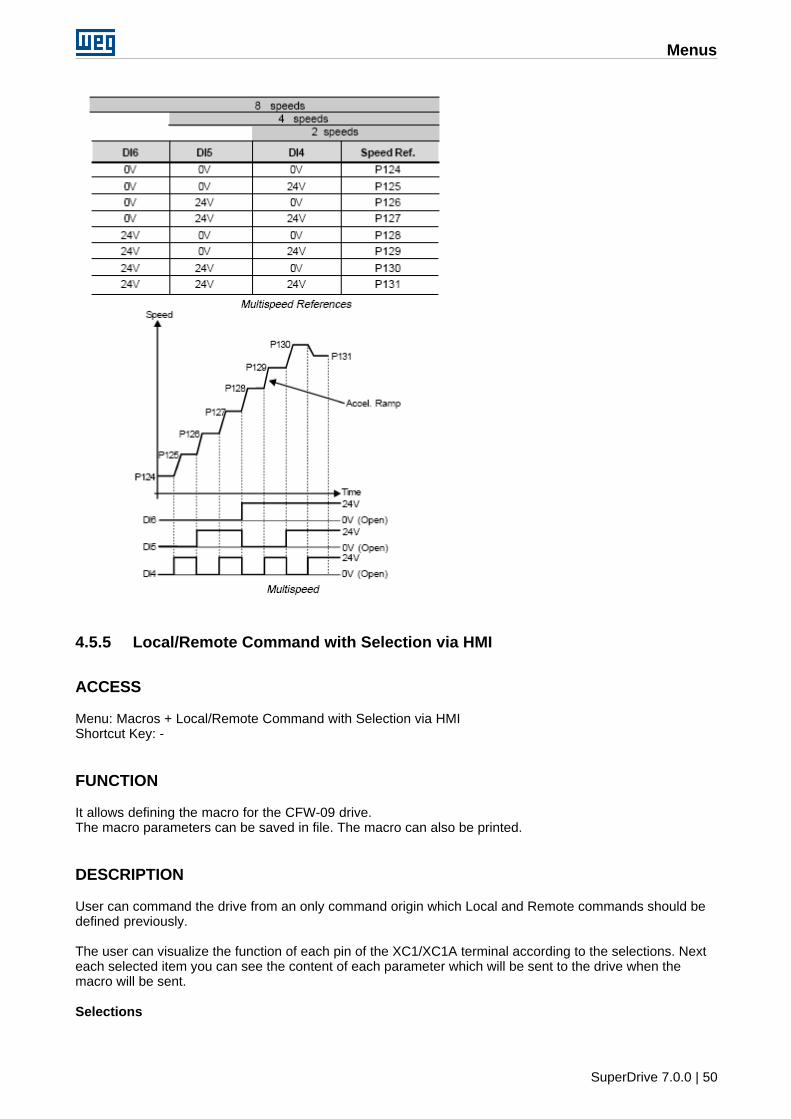
Menus
SuperDrive 7.0.0 | 50
4.5.5 Local/Remote Command with Selection via HMI
ACCESS
Menu: Macros + Local/Remote Command with Selection via HMIShortcut Key: -
FUNCTION
It allows defining the macro for the CFW-09 drive.The macro parameters can be saved in file. The macro can also be printed.
DESCRIPTION
User can command the drive from an only command origin which Local and Remote commands should bedefined previously.
The user can visualize the function of each pin of the XC1/XC1A terminal according to the selections. Nexteach selected item you can see the content of each parameter which will be sent to the drive when themacro will be sent.
Selections
Menus
SuperDrive 7.0.0 | 51
Local Command:· HMI
Remote Command:· Terminals
File Name - file name to save the macro.Save - saves the macro in file.Search - it allows selecting a file with the macro.Print - it prints the macro.Send - it sends the macro to the drive.See orientative diagram - a new window is opened, where the diagram is orientative and corresponds to astandard factory configuration. It does not correspond to the user selected configuration.
4.5.6 Local Command with Reference via HMI and 3-Wire Start/Stop
ACCESS
Menu: Macros + Local Command with Reference via HMI and 3-Wire Start/StopShortcut Key: -
FUNCTION
It allows defining the macro for the CFW-09 drive.The macro parameters can be saved in file. The macro can also be printed.
DESCRIPTION
User can command the drive from an only command origin which Speed Reference Commands/ Run/StopCommand and Direction of Rotation Command should be defined previously.
The user can visualize the function of each pin of the XC1/XC1A terminal according to the selections. Nexteach selected item you can see the content of each parameter which will be sent to the drive when themacro will be sent.
Selections
Speed Reference:· HMI
Command Run/Stop:· Terminals
· Direction of rotation· Terminal
File Name - file name to save the macro.Save - saves the macro in file.Search - it allows selecting a macro file.Print - it prints the macro.Send - it sends the macro to the drive.See orientative diagram - a new window is opened, where the diagram is orientative and corresponds to astandard factory configuration. It does not correspond to the selected user configuration.
Menus
SuperDrive 7.0.0 | 52
4.6 Tools
Drives Network
Update parameters to other fimrware version
Language
Options
4.6.1 Drives Network
ACCESS
Menu: Tools + Drives networkShortcut Key: -
FUNCTION
Permits displaying all drives (1...30) that are connected to the SuperDrive or configured only.
DESCRIPTION
Following data can be displayed:· Address· Type· Firmware Version· Nominal Voltage· Nominal Current· Tag
4.6.2 Update Parameters to Other Firmware Version
ACCESS
Menu: Tools + Update parameters to other firmware versionShortcut Key: -
FUNCTION
This tool was designed for updating CFW-09 parameters from the original firmware version, where theparameters were created, to a different firmware version.
DESCRIPTION
When selecting this tool, the user shall indicate the firmware version to which the parameters of each driveon the network will be converted.The conversion is performed and the parameters that were changed are presented to the user. Theparameters that cannot be automatically updated will be loaded with the factory default value. The user willstill be able to change the parameters manually.The project shall be saved with a different name, so that the existing information is not lost.
Menus
SuperDrive 7.0.0 | 53
Currently, the following versions have the automatic updating function:· v2.4x· v2.6x· v3.1x· v3.7x· v4.0x· v4.4x
Any update between these versions can be automatically performed. Versions that were not listed abovecan be manually updated by using this tool.
Example:
· The parameters of a CFW-09 v2.42 were read and stored on the PC.· The drive was replaced by a CFW-09 v2.64.· It is desired to transfer the CFW-09 v2.42 parameters stored on the PC to the new CFW-09 v2.64 drive.· The group of parameters is different since we have different software versions.· One example is parameter P404. When it is set to 9 on version 2.42 we have 6.0 HP/4.5 kW; when it is
set to 9 on version 2.64 we have 5.5 HP/4.0 kW.· By using this tool the contents will be converted and it will be possible to transfer them to the drive.
4.6.3 Language
ACCESS
Menu: Tools + LanguageShortcut Key: -
FUNCTION
Selects the message language.
DESCRIPTION
You can select between Portuguese, English or Spanish.After user confirmation, SuperDrive shows the messages in the selected language.
4.6.4 Options
ACCESS
Menu: Tools + OptionsShortcut Key: -
FUNCTION
Displays the option windows, where the user can configure the SuperDrive.
DESCRIPTION
Sound a tone
Menus
SuperDrive 7.0.0 | 54
When activated, a bip is emitted in various situations, such as when the widows are closed, when a value isinserted in a text input box, when a drive is detected in the automatic network identification, etc.
Confirmation when exiting the programWhen activated, a message confirming the exit is presented when the user closes the SuperDrive.
Confirmation message to continueWhen activated, a message asks the user to confirm the execution continuation.This happens with the following functions:1- Close project2- Read from drive3- Write to the drive4 - Identify drives / search for drives automatically
Example:Before the parameters download is executed (read the drive), the user must confirm this operation.
Background colorThis enables user to select a background color, using a dialogue box of standard Windows colors. The usercan select between the standard colors or he can create and select a personalized color.
StandardAfter user's confirmation all configurations returns to the default values. Also the windows position and size(those that can be changed) will be changed to the default values.
Shows the Warning window during the initializationWhen activated, the windows Warning is always displayed during the SuperDrive initialization
Test of the serial port during initializationWhen activated, the configured serial port is tested during the SuperDrive initialization.If any error occurs, the communication setting windows is open and the user can select another serial port(COM1...COM16).
Narrowing Effect during Windows ClosingWhen activated, the windows is narrowed during closing in so many steps as selected on the slide bar(1...100).The higher the number selected on the slide bar, the slower will be the closing of the windows, giving ashrinkage effect.
Projects pathAllows the user to select the path where the projects of the SuperDrive must be saved.
4.7 Help
Topics
About SuperDrive
4.7.1 Topics
ACCESS
Menu: Help + TopicsShortcut Key: -
FUNCTION
Menus
SuperDrive 7.0.0 | 55
Shows the Help Window of the SuperDrive.
DESCRIPTION
The user can select on of the following tables:
ContentThe manual is distributed by topics and divided in subjects.
IndexThe user analyze the manual by entering a known keyword.
LocalizeThe user localizes the subject by topics shown in alphabetic order.
4.7.2 About SuperDrive
ACCESS
Menu: Help + About SuperDriveShortcut Key: -
FUNCTION
Displays the window with information about SuperDrive.
DESCRIPTION
This window displays the number of the version, copyrights and system information.
Wizards
SuperDrive 7.0.0 | 56
5 Wizards
A Wizard is a tool which leads a user step-by-step to program drives.
Three wizards tools are available that are automatically activated by SuperDrive. These wizards tools areactivated during serial communication.
Initial Power-up Wizard
Control Setting Wizard
Self-Tuning Wizard
5.1 Initial Power-up Wizard
CFW-09This wizard will guide the user through sequential steps. Parameters P201, P296, P400, P401, P403, P402,P404, P406 will be programmed in this wizard.
MVW-01This wizard will guide the user through sequential steps. Parameters P201, P400, P401, P403, P402 will beprogrammed in this wizard.
5.2 Control Setting Wizard
VECTOR CONTROL
CFW-09This wizard will guide the user through sequential steps. Parameters P400, P401, P403, P402, P404, P406,P408, P409, P410, P411, P412, P413 will be programmed in this wizard.
MVW-01This wizard will guide the user through sequential steps. Parameters P400, P401, P402, P403, P404, P405,P406, P408, P409, P410, P411, P412, P413 will be programmed in this wizard.
VVW CONTROL
CFW-09This wizard will guide the user through sequential steps. Parameters P400, P401, P403, P402, P404, P406,P407, P399, P408, P409 will be programmed in this wizard.
5.3 Self-Tuning Wizard
CFW-09This wizard will guide the user through sequential steps. Parameters P409, P410, P411, P412, P413 will beestimated automatically by the drive.
Serial Communication
SuperDrive 7.0.0 | 57
6 Serial Communication
Drive Parametrization
Protocol
RS232
RS485
Adam 4520
IC109A
MIW-02
Serial Communication Errors
USB Serial Converter
6.1 Drive Parametrization
The following parameters must be set as below:
Drive Connection Type Parameter Description SuperDrive Default
CFW-05 RS232/RS485307 Serial Bit Rate (bit/s) 6 = 9600
308 Drive Address 1
CFW-07 RS232/RS485 308 Drive Address 1
CFW-08 RS232/RS485
308 Drive Address 1
312Serial
CommunicationProtocol
0 = WEGBUS
CFW-09 RS232/RS485
308 Drive Address 1
309 Fieldbus 0 = Disable
312Serial
CommunicationProtocol
0 = WEGBUS
CTW-04 RS232/RS485
65DI Function
(XC1:37)
1 = operation viaserial (WEGBUS) or
DI
83 Serial WEGBUS 1 = 9600 bps
84 Drive Address 1
85 FieldBus 0 = Inactive
MVW-01 RS232/RS485
308 Drive Address 1
309 Fieldbus 0 = Disable
312Serial
CommunicationProtocol
0 = WEGBUS
SCA-04 RS232/RS485
55 Drive Address 1
48Serial
CommunicationProtocol
0 = 7 bits + 1 paritybit
SCA-05 RS232/RS485
308 Drive Address 1
310 Serial Bit Rate 1 = 9600 bits/s
311 Data Bits, Parity, 7=7bits, even parity,
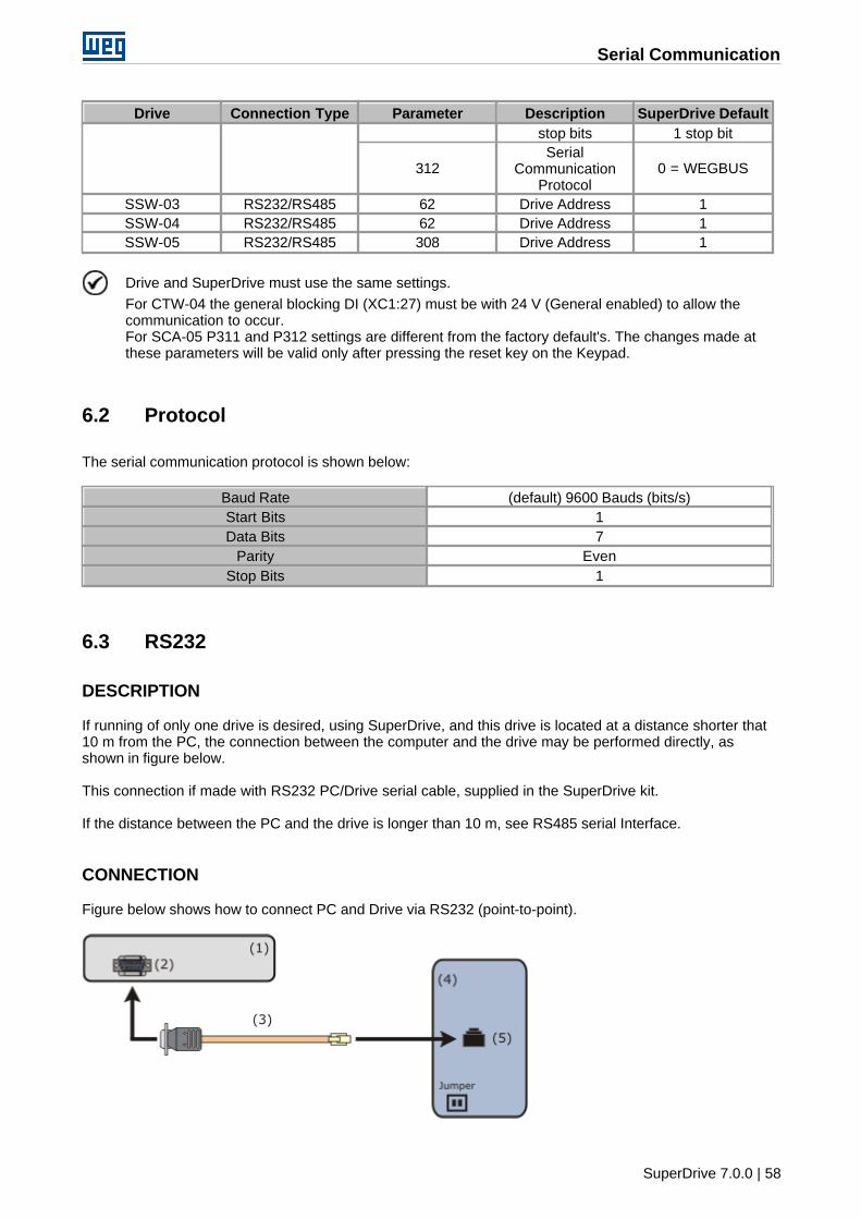
Serial Communication
SuperDrive 7.0.0 | 58
Drive Connection Type Parameter Description SuperDrive Default
stop bits 1 stop bit
312Serial
CommunicationProtocol
0 = WEGBUS
SSW-03 RS232/RS485 62 Drive Address 1
SSW-04 RS232/RS485 62 Drive Address 1
SSW-05 RS232/RS485 308 Drive Address 1
Drive and SuperDrive must use the same settings.
For CTW-04 the general blocking DI (XC1:27) must be with 24 V (General enabled) to allow thecommunication to occur.For SCA-05 P311 and P312 settings are different from the factory default's. The changes made atthese parameters will be valid only after pressing the reset key on the Keypad.
6.2 Protocol
The serial communication protocol is shown below:
Baud Rate (default) 9600 Bauds (bits/s)
Start Bits 1
Data Bits 7
Parity Even
Stop Bits 1
6.3 RS232
DESCRIPTION
If running of only one drive is desired, using SuperDrive, and this drive is located at a distance shorter that10 m from the PC, the connection between the computer and the drive may be performed directly, asshown in figure below.
This connection if made with RS232 PC/Drive serial cable, supplied in the SuperDrive kit.
If the distance between the PC and the drive is longer than 10 m, see RS485 serial Interface.
CONNECTION
Figure below shows how to connect PC and Drive via RS232 (point-to-point).
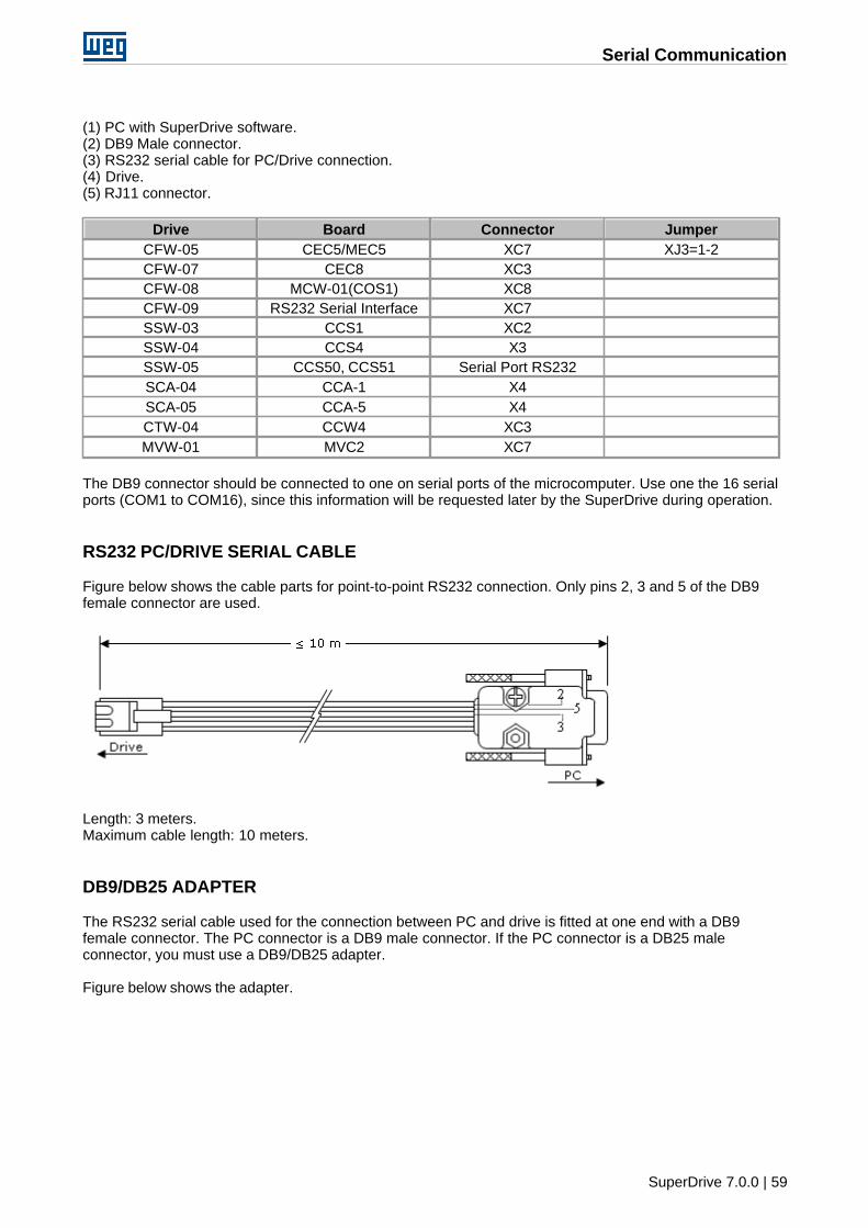
Serial Communication
SuperDrive 7.0.0 | 59
(1) PC with SuperDrive software.(2) DB9 Male connector.(3) RS232 serial cable for PC/Drive connection.(4) Drive.(5) RJ11 connector.
Drive Board Connector Jumper
CFW-05 CEC5/MEC5 XC7 XJ3=1-2
CFW-07 CEC8 XC3
CFW-08 MCW-01(COS1) XC8
CFW-09 RS232 Serial Interface XC7
SSW-03 CCS1 XC2
SSW-04 CCS4 X3
SSW-05 CCS50, CCS51 Serial Port RS232
SCA-04 CCA-1 X4
SCA-05 CCA-5 X4
CTW-04 CCW4 XC3
MVW-01 MVC2 XC7
The DB9 connector should be connected to one on serial ports of the microcomputer. Use one the 16 serialports (COM1 to COM16), since this information will be requested later by the SuperDrive during operation.
RS232 PC/DRIVE SERIAL CABLE
Figure below shows the cable parts for point-to-point RS232 connection. Only pins 2, 3 and 5 of the DB9female connector are used.
Length: 3 meters.Maximum cable length: 10 meters.
DB9/DB25 ADAPTER
The RS232 serial cable used for the connection between PC and drive is fitted at one end with a DB9female connector. The PC connector is a DB9 male connector. If the PC connector is a DB25 maleconnector, you must use a DB9/DB25 adapter.
Figure below shows the adapter.
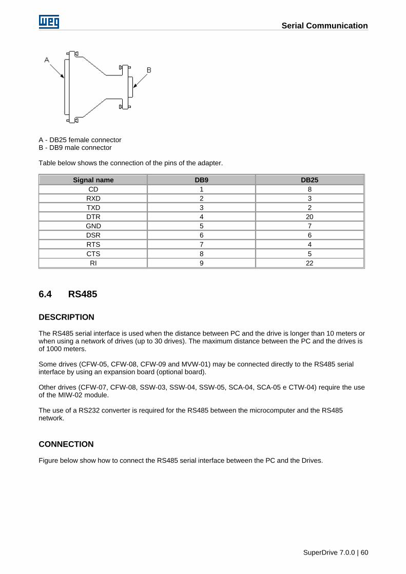
Serial Communication
SuperDrive 7.0.0 | 60
A - DB25 female connectorB - DB9 male connector
Table below shows the connection of the pins of the adapter.
Signal name DB9 DB25
CD 1 8
RXD 2 3
TXD 3 2
DTR 4 20
GND 5 7
DSR 6 6
RTS 7 4
CTS 8 5
RI 9 22
6.4 RS485
DESCRIPTION
The RS485 serial interface is used when the distance between PC and the drive is longer than 10 meters orwhen using a network of drives (up to 30 drives). The maximum distance between the PC and the drives isof 1000 meters.
Some drives (CFW-05, CFW-08, CFW-09 and MVW-01) may be connected directly to the RS485 serialinterface by using an expansion board (optional board).
Other drives (CFW-07, CFW-08, SSW-03, SSW-04, SSW-05, SCA-04, SCA-05 e CTW-04) require the useof the MIW-02 module.
The use of a RS232 converter is required for the RS485 between the microcomputer and the RS485network.
CONNECTION
Figure below show how to connect the RS485 serial interface between the PC and the Drives.
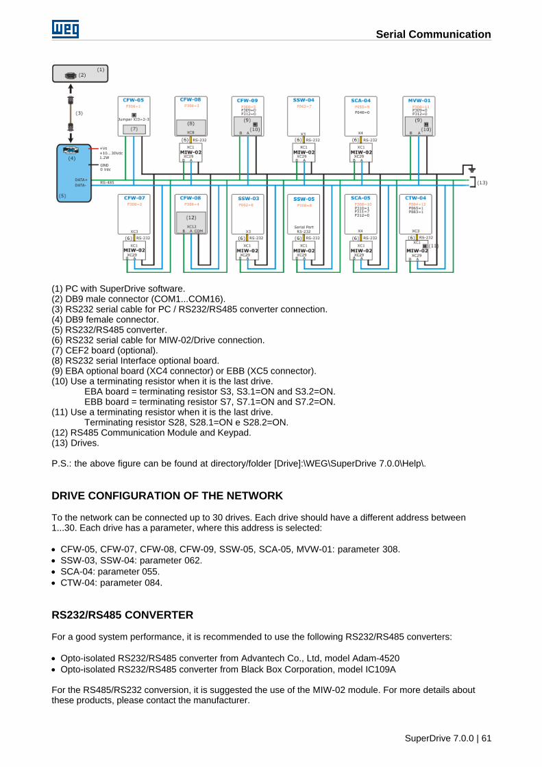
Serial Communication
SuperDrive 7.0.0 | 61
(1) PC with SuperDrive software.(2) DB9 male connector (COM1...COM16).(3) RS232 serial cable for PC / RS232/RS485 converter connection.(4) DB9 female connector.(5) RS232/RS485 converter.(6) RS232 serial cable for MIW-02/Drive connection.(7) CEF2 board (optional).(8) RS232 serial Interface optional board.(9) EBA optional board (XC4 connector) or EBB (XC5 connector).(10) Use a terminating resistor when it is the last drive.
EBA board = terminating resistor S3, S3.1=ON and S3.2=ON.EBB board = terminating resistor S7, S7.1=ON and S7.2=ON.
(11) Use a terminating resistor when it is the last drive.Terminating resistor S28, S28.1=ON e S28.2=ON.
(12) RS485 Communication Module and Keypad.(13) Drives.
P.S.: the above figure can be found at directory/folder [Drive]:\WEG\SuperDrive 7.0.0\Help\.
DRIVE CONFIGURATION OF THE NETWORK
To the network can be connected up to 30 drives. Each drive should have a different address between1...30. Each drive has a parameter, where this address is selected:
· CFW-05, CFW-07, CFW-08, CFW-09, SSW-05, SCA-05, MVW-01: parameter 308.· SSW-03, SSW-04: parameter 062.· SCA-04: parameter 055.· CTW-04: parameter 084.
RS232/RS485 CONVERTER
For a good system performance, it is recommended to use the following RS232/RS485 converters:
· Opto-isolated RS232/RS485 converter from Advantech Co., Ltd, model Adam-4520· Opto-isolated RS232/RS485 converter from Black Box Corporation, model IC109A
For the RS485/RS232 conversion, it is suggested the use of the MIW-02 module. For more details aboutthese products, please contact the manufacturer.
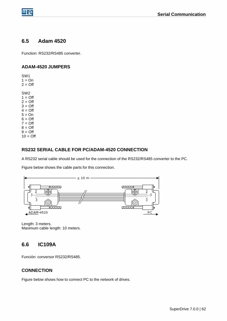
Serial Communication
SuperDrive 7.0.0 | 62
6.5 Adam 4520
Function: RS232/RS485 converter.
ADAM-4520 JUMPERS
SW11 = On2 = Off
SW21 = Off2 = Off3 = Off4 = Off5 = On6 = Off7 = Off8 = Off9 = Off10 = Off
RS232 SERIAL CABLE FOR PC/ADAM-4520 CONNECTION
A RS232 serial cable should be used for the connection of the RS232/RS485 converter to the PC.
Figure below shows the cable parts for this connection.
Length: 3 meters.Maximum cable length: 10 meters.
6.6 IC109A
Función: conversor RS232/RS485.
CONNECTION
Figure below shows how to connect PC to the network of drives.
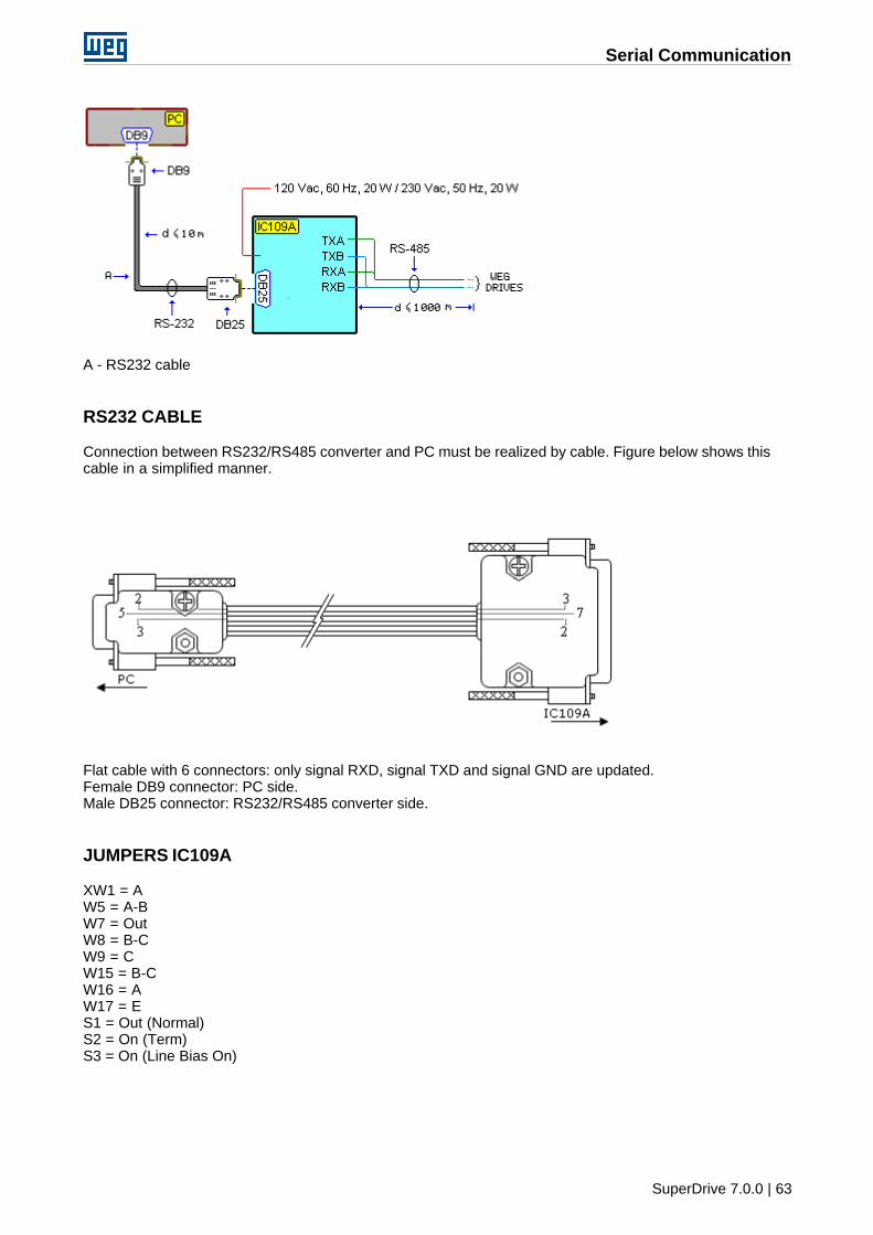
Serial Communication
SuperDrive 7.0.0 | 63
A - RS232 cable
RS232 CABLE
Connection between RS232/RS485 converter and PC must be realized by cable. Figure below shows thiscable in a simplified manner.
Flat cable with 6 connectors: only signal RXD, signal TXD and signal GND are updated.Female DB9 connector: PC side.Male DB25 connector: RS232/RS485 converter side.
JUMPERS IC109A
XW1 = AW5 = A-BW7 = OutW8 = B-CW9 = CW15 = B-CW16 = AW17 = ES1 = Out (Normal)S2 = On (Term)S3 = On (Line Bias On)
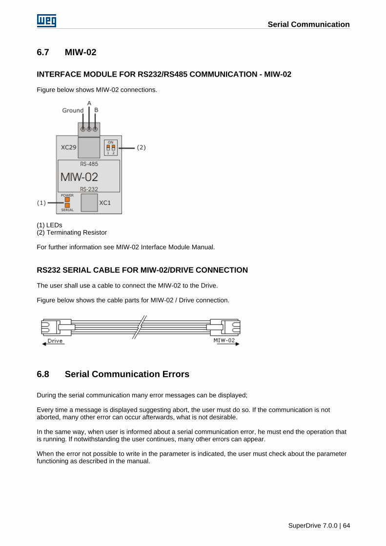
Serial Communication
SuperDrive 7.0.0 | 64
6.7 MIW-02
INTERFACE MODULE FOR RS232/RS485 COMMUNICATION - MIW-02
Figure below shows MIW-02 connections.
(1) LEDs(2) Terminating Resistor
For further information see MIW-02 Interface Module Manual.
RS232 SERIAL CABLE FOR MIW-02/DRIVE CONNECTION
The user shall use a cable to connect the MIW-02 to the Drive.
Figure below shows the cable parts for MIW-02 / Drive connection.
6.8 Serial Communication Errors
During the serial communication many error messages can be displayed;
Every time a message is displayed suggesting abort, the user must do so. If the communication is notaborted, many other error can occur afterwards, what is not desirable.
In the same way, when user is informed about a serial communication error, he must end the operation thatis running. If notwithstanding the user continues, many other errors can appear.
When the error not possible to write in the parameter is indicated, the user must check about the parameterfunctioning as described in the manual.
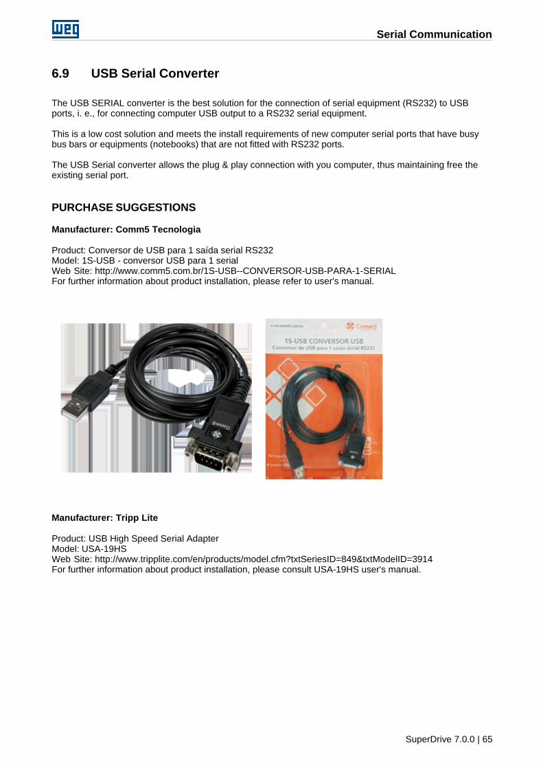
Serial Communication
SuperDrive 7.0.0 | 65
6.9 USB Serial Converter
The USB SERIAL converter is the best solution for the connection of serial equipment (RS232) to USBports, i. e., for connecting computer USB output to a RS232 serial equipment.
This is a low cost solution and meets the install requirements of new computer serial ports that have busybus bars or equipments (notebooks) that are not fitted with RS232 ports.
The USB Serial converter allows the plug & play connection with you computer, thus maintaining free theexisting serial port.
PURCHASE SUGGESTIONS
Manufacturer: Comm5 Tecnologia
Product: Conversor de USB para 1 saída serial RS232Model: 1S-USB - conversor USB para 1 serialWeb Site: http://www.comm5.com.br/1S-USB--CONVERSOR-USB-PARA-1-SERIALFor further information about product installation, please refer to user's manual.
Manufacturer: Tripp Lite
Product: USB High Speed Serial AdapterModel: USA-19HSWeb Site: http://www.tripplite.com/en/products/model.cfm?txtSeriesID=849&txtModelID=3914For further information about product installation, please consult USA-19HS user's manual.

Serial Communication
SuperDrive 7.0.0 | 66
Solving Problems
SuperDrive 7.0.0 | 67
7 Solving Problems
Printing Problem
Communication Problem
7.1 Printing Problem
The screen and the printing resolution are not frequently the same. Thus when you are printing, the resultsmay be not the same as seen on the screen.
Thus, if general protection fault is shown when you are printing some topic, check the printer driver. Ifpossible, change to a more updated version of the driver.
Assure that the printer is activated and that you can print from any application. If even thus the problempersists, open the property page of the printer that you are using. Select the properties that better matchesyour system.
7.2 Communication Problem
If SuperDrive does not communicate with the Drive
· Check if the serial cable is properly working and if you are using the correct cable model. Check if thereis no disconnected wire on the cable, if the cable pinout is correct or if the cable is well connected.
· Check if you are using the correct drive address and if the project on SuperDrive indicates the sameaddress. Also check if the drive communication protocol is correct (WEGBUS).
· Check equipment jumpers: see drive Manual.
· Check if the PC serial port (COM1...COM16) selected in the SuperDrive is the same where the cable isconnected.
· Turned off drive, disconnect and connect the cable again, turn on the drive again.
· Interrupt request of Windows for the serial ports (COMxx) not correctly configured: check on controlpanel the item [Device Manager > Ports]. If possible, use default configurations. The window must showthat there is no conflict with other devices.
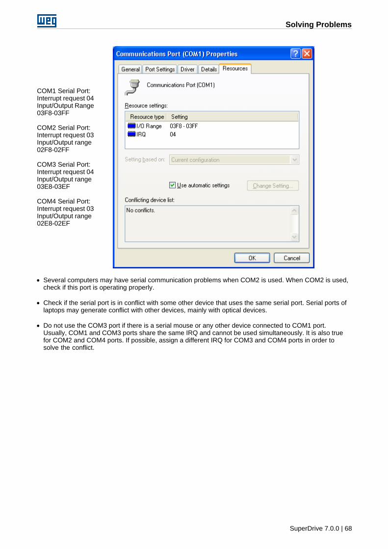
Solving Problems
SuperDrive 7.0.0 | 68
COM1 Serial Port:Interrupt request 04Input/Output Range03F8-03FF
COM2 Serial Port:Interrupt request 03Input/Output range02F8-02FF
COM3 Serial Port:Interrupt request 04Input/Output range03E8-03EF
COM4 Serial Port:Interrupt request 03Input/Output range02E8-02EF
· Several computers may have serial communication problems when COM2 is used. When COM2 is used,check if this port is operating properly.
· Check if the serial port is in conflict with some other device that uses the same serial port. Serial ports oflaptops may generate conflict with other devices, mainly with optical devices.
· Do not use the COM3 port if there is a serial mouse or any other device connected to COM1 port.Usually, COM1 and COM3 ports share the same IRQ and cannot be used simultaneously. It is also truefor COM2 and COM4 ports. If possible, assign a different IRQ for COM3 and COM4 ports in order tosolve the conflict.
SuperDrive 7.0.0 | 69
Index
Index
- A -About SuperDrive 55
Acquire Parameter 36
Adam 4520 62
Always Local Command 45
Always Remote Command 47
Application Data 26
- B -Basic Application 44
Before Installing SuperDrive 8
- C -Close 22
Communication Problem 67
Communication Settings 43
Control Setting Wizard 56
Copyright Notice 6
Customer Data 26
- D -Drive Data 27
Drive Parametrization 57
DriveBar 24
Drives Network 52
- E -End User Data 27
Error Log 42
Exit 24
- H -Help 54
- I -IC109A 62
Identify Drives 43
Initial Power-up Wizard 56
Installation Instructions 8
Installing SuperDrive 15
- L -Language 53
License 7
Local Command with Reference via HMI and 3-WireStart/Stop 51
Local/Remote Command with Selection via HMI 50
- M -Macros 44
Main Features 5
Menus 20
Migrating from Previous Versions 6
Minimum Requirements 8
MIW-02 64
Monitor Parameters 30
Monitor Parameters using Modem 31
Monitor Using Keypad 30
Motor Data 27
Multispeed with Commands via Digital Inputs 48
- N -New 21
- O -Offline 25
Online 28
Online Graph 39
Open 21
Options 53
- P -Parameters 25
Print 23
Print Setup 23
Printing Problem 67
Project 21
Project Architecture 18
Protocol 58
- R -Read Parameters 29
Remove 22
SuperDrive 7.0.0 | 70
Index
RS232 58
RS485 60
- S -Safety Warning 6
Save As 22
Select Drive Address 28
Self-Tuning Wizard 56
Serial Communication 57
Serial Communication Errors 64
Solving Problems 67
StatusBar 25
SuperDrive 7.0.0 5
SuperDrive Architecture 17
SuperDrive Structure 17
Supported Drives 9
- T -ToolBar 24
Tools 52
Topics 54
Trace Function 40
- U -Uninstalling SuperDrive 16
Update Parameters to Other Firmware Version 52
USB Serial Converter 65
User's Manual - PDF 7
- V -View 24
View Chart 38
- W -Welcome 5
What's New 6
Wizards 56
Write Parameters 29


![ForeScout CounterACT Supplemental Administrative … Secure Acceptance, Installation, and Configuration ... CounterACT® Installation Guide Version 7.0.0 [2] CounterACT® Console User](https://img.pdfslide.net/doc/110x75/5b0d73937f8b9a685a8e27f5/forescout-counteract-supplemental-administrative-secure-acceptance-installation.jpg)