Embed Size (px)
Citation preview
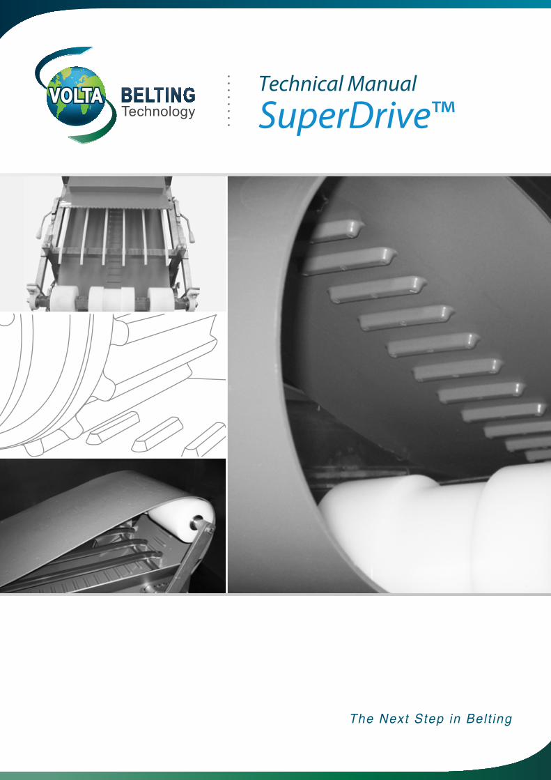
Technical Manual
SuperDrive™
The Next Step in Bel t ing

2 Volta Belting Technology Ltd.
SuperDrive™ Technical MMaanuuaal
Table of Contents Page
1. Introduction 32. Technical Data 4
Volta ‘M’ Material SuperDrive™ Belts 6-7Volta “LT” Low Temperature Material SuperDrive™ Belts 8-9
3. Accessories 10Drive, Tail & Support Pulleys 10Pulley Bore Description 11Securing SuperDrive™ Pulleys: Locking Collars 11Motorized Pulley 12
4. Conveyor Construction 13Classic Conveyor Construction 13Conveyor Construction Guidelines; Slidebed Construction 13Return Rollers 14Standard Belt Tensioners 14Quick Release Tensioner 14Snub Rollers 14
“Z” or Swanneck Conveyor Construction 16-1791-81 sroyevnoC hguorT
Centre Drive Conveyor 20Removing Belt for Cleaning 20
5. Splicing the SuperDrive™ 21FT – Electrode Welding Kit 21FBW Flat Butt Welding Tool 21
22 ecaL lateM32 ecaL egniH citsalP
6. Belt Calculations 24Pull Force Calculation Procedure 24-25Determine the number of Support Pulleys Required 26Installation & Positioning of Support Pulleys 27Calculation Example 28-29
7. Motor Capacity Calculation 308. Frequently Asked Questions 31
3www.voltabelting.com
1. Introduction
Material Features
Mechanical Benefits
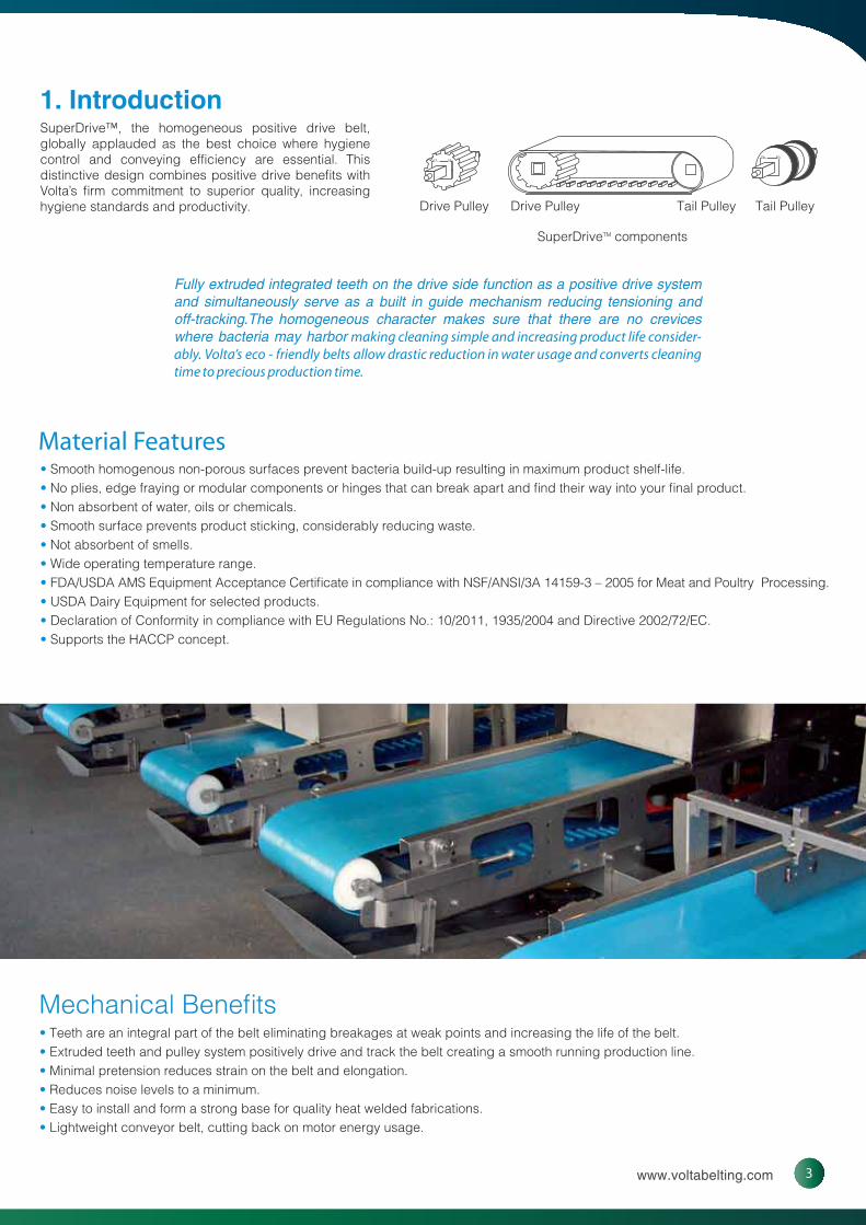
Fully extruded integrated teeth on the drive side function as a positive drive system and simultaneously serve as a built in guide mechanism reducing tensioning and off-tracking.The homogeneous character makes sure that there are no crevices where bacteria may harbor making cleaning simple and increasing product life consider-ably. Volta’s eco - friendly belts allow drastic reduction in water usage and converts cleaning time to precious production time.
SuperDrive™, the homogeneous positive drive belt, globally applauded as the best choice where hygiene control and conveying efficiency are essential. This distinctive design combines positive drive benefits with Volta’s firm commitment to superior quality, increasing hygiene standards and productivity. Drive Pulley Drive Pulley Tail PulleyTail Pulley
SuperDriveTM components
• Smooth homogenous non-porous surfaces prevent bacteria build-up resulting in maximum product shelf-life.• No plies, edge fraying or modular components or hinges that can break apart and find their way into your final product.• Non absorbent of water, oils or chemicals.• Smooth surface prevents product sticking, considerably reducing waste.• Not absorbent of smells.• Wide operating temperature range.• FDA/USDA AMS Equipment Acceptance Certificate in compliance with NSF/ANSI/3A 14159-3 – 2005 for Meat and Poultry Processing.• USDA Dairy Equipment for selected products.• Declaration of Conformity in compliance with EU Regulations No.: 10/2011, 1935/2004 and Directive 2002/72/EC.• Supports the HACCP concept.
• Teeth are an integral part of the belt eliminating breakages at weak points and increasing the life of the belt.• Extruded teeth and pulley system positively drive and track the belt creating a smooth running production line. • Minimal pretension reduces strain on the belt and elongation.• Reduces noise levels to a minimum. • Easy to install and form a strong base for quality heat welded fabrications.• Lightweight conveyor belt, cutting back on motor energy usage.
4 Volta Belting Technology Ltd.
SuperDrive™ Technical MMaanuuaal
2. Technical Data
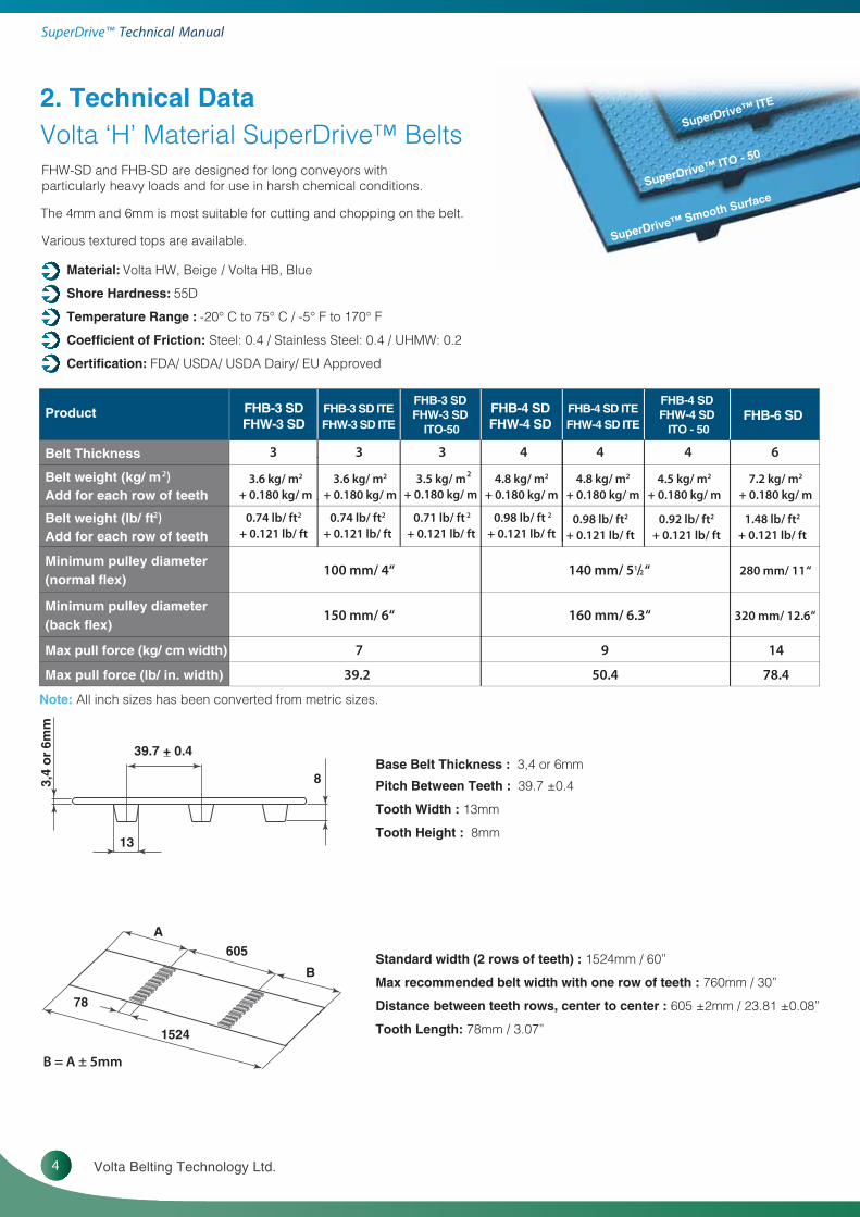
Standard width (2 rows of teeth) : 1524mm / 60”
Max recommended belt width with one row of teeth : 760mm / 30”
Distance between teeth rows, center to center : 605 ±2mm / 23.81 ±0.08”
Tooth Length: 78mm / 3.07”
Base Belt Thickness : 3,4 or 6mm
Pitch Between Teeth : 39.7 ±0.4
Tooth Width : 13mm
Tooth Height : 8mm
Note: All inch sizes has been converted from metric sizes.
8
13
39.7 + 0.4
3,4
or
6mm
B
A605
78
1524
B = A ± 5mm
Volta ‘H’ Material SuperDrive™ BeltsFHW-SD and FHB-SD are designed for long conveyors with particularly heavy loads and for use in harsh chemical conditions.
Various textured tops are available.
The 4mm and 6mm is most suitable for cutting and chopping on the belt.
Material: Volta HW, Beige / Volta HB, Blue
Shore Hardness: 55D
Temperature Range : -20° C to 75° C / -5° F to 170° F
Coefficient of Friction: Steel: 0.4 / Stainless Steel: 0.4 / UHMW: 0.2
Certification: FDA/ USDA/ USDA Dairy/ EU Approved
ProductFHB-3 SDFHW-3 SD
ITO-50
FHB-3 SDFHW-3 SD
FHB-3 SD ITEFHW-3 SD ITE
FHB-4 SDFHW-4 SD
FHB-6 SDFHB-4 SD ITEFHW-4 SD ITE
FHB-4 SD FHW-4 SD
ITO - 50
Belt Thickness
Belt weight (kg/ m2)Add for each row of teeth
3 33
3.6 kg/ m2 + 0.180 kg/ m
3.6 kg/ m2 + 0.180 kg/ m
23.5 kg/ m + 0.180 kg/ m
4.8 kg/ m2 + 0.180 kg/ m
4.8 kg/ m2 + 0.180 kg/ m
4.5 kg/ m2
+ 0.180 kg/ m7.2 kg/ m2
+ 0.180 kg/ m
Belt weight (lb/ ft2)Add for each row of teeth
0.74 lb/ ft2
+ 0.121 lb/ ft0.74 lb/ ft2
+ 0.121 lb/ ft 0.71 lb/ ft 2
+ 0.121 lb/ ft
4 44 6
0.98 lb/ ft 2
+ 0.121 lb/ ft 0.98 lb/ ft2
+ 0.121 lb/ ft0.92 lb/ ft2
+ 0.121 lb/ ft1.48 lb/ ft2
+ 0.121 lb/ ft
Minimum pulley diameter (normal flex)
100 mm/ 4“ 140 mm/ 51/2 “ 280 mm/ 11 “
Minimum pulley diameter (back flex)
150 mm/ 6“ 160 mm/ 6.3“ 320 mm/ 12.6“
Max pull force (kg/ cm width) 97 14
Max pull force (lb/ in. width) 39.2 50.4 78.4
SuperDrive™ ITO - 50
SuperDrive™ ITE
SuperDrive™ Smooth Surface

5www.voltabelting.com
Pulleys: when choosing the pulley size , it must be equal to or larger than the minimum pulley required.
Flights:can be welded on top of a tooth but they must not exceed the width of the tooth or between teeth. Flights can not be welded where pulley teeth make contact with the belt when driving it.
Pulley Guidelines & Fabrication Options
DS 4-BHF / DS 4-WHFDS 3-BHF / DS 3-WHFepyT tleB
MPD Base Belt 100mm 4” 140mm 5.50”
Minimum Pulley Diameter for V-Cleat
Electrode 132mm 5.20” 155mm 6.10”
VW / VWB 10 157mm 6.18” 175mm 6.89”
VW / VWB 13 177mm 6.97” 200mm 7.87”
VW / VWB 17 217mm 8.54” 240mm 9.45”
Minimum Pulley Diameter for Flat Electrode Welded Flights
Single Electrode 7 157mm 6.18” 180mm 7.08”
Single Electrode 9 177mm 6.97” 200mm 7.87”
Double Electrode 7 192mm 7.56” 215mm 8.46”
Double Electrode 9 RNRN
Table 2.2
Note: NR - Not Recommended. Contact your local distributor for further details regarding the 6mm thick SuperDrive™ belt.
Recommended Flights Welding location
* Locations 1 & 4 are not recommended because the cleat is on top of the pulley teeth driving area.* Location 2 & 3 are the recommended ones.
Note: In location 2, it is essential that the cleat and weld widths do not exceed the width of the belt tooth.
3 4 2 1
Pulley teeth driving area

6 Volta Belting Technology Ltd.
SuperDrive™ Technical MMaanuuaal
Base Belt Thickness : 3, 4 or 6mm
Pitch Between Teeth : 39.7 ±0.4
Standard width (2 rows of teeth) : 1524mm / 60”
Max recommended belt width with one row of teeth : 760mm / 30”
Distance between teeth rows, center to center : 613 ±2mm / 24.13 ±0.08”
Tooth Length: 78mm / 3.07”
Tooth Width : 13mm
Tooth Height : 8mm
8
13
39.7 + 0.4
3, 4
or
6mm
B
A613
78
1524
B = A ± 5mm
FMW-SD and FMB-SD are designed for shorter conveyors with lighter loads and where fabrications or sidewalls are needed.We highly recommend using FMW-3-SD and FMB-3-SD with bigger pulleys for low temperature applications.
Material: Volta MW, Beige / Volta MB, Blue
Shore Hardness: 53D
Temperature Range : -20° C to 60° C / -5° F to 140° F
Coefficient of Friction: Steel: 0.5 / Stainless Steel: 0.5 / UHMW: 0.28
Certification: FDA/ USDA/ USDA Dairy/ EU Approved
Technical Data
Volta ‘M’ Material SuperDrive™ Belts
Product FMB-3 SDFMW-3 SD
FMB-3 SD ITEFMW-3 SD ITE
FMB-3 SD ITO - 50
FMB-4 SDFMW-4 SD
FMB-6 SD
Belt Thickness 433
Belt weight (kg/ m 2)Add for each row of teeth
3 6
3.6 kg/ m 2 + 0.180 kg/ m
3.5 kg/ m2 + 0.180 kg/ m
4.8 kg/ m 2 + 0.180 kg/ m
7.2 kg/ m 2 + 0.180 kg/ m
Belt weight (lb/ ft 2)Add for each row of teeth
0.74 lb/ ft 2 + 0.121 lb/ ft
3.6 kg/ m 2
+ 0.180 kg/ m
0.74 lb/ ft 2
+ 0.121 lb/ ft0.71 lb/ ft2
+ 0.121 lb/ ft0.98 lb/ ft 2
+ 0.121 lb/ ft1.48 lb/ ft 2
+ 0.121 lb/ ft
Minimum pulley diameter (normal flex)*
80 mm/ 31/4 “ 120 mm/4 3/4” 240 mm/ 9.45”
Minimum pulley diameter (back flex)*
100 mm/ 4” 150 mm/ 6” 280 mm/ 11”
Max pull force (kg/ cm width) 6.25 8 12.5
Max pull force (lb/ in. width) 35 44.8 70
Note: *All inch sizes have been converted from metric sizes.
SuperDrive™ ITO - 50
SuperDrive™ ITE
SuperDrive™ Smooth Surface

7www.voltabelting.com
Electrode welded cleats: we recommend welding the cleats above the teeth location and cleat thickness should not exceed the tooth base width.
Sidewalls: must be positioned at a minimum distance of 100mm from the belt teeth.
Flights: can be welded on top of a tooth but they must not exceed the width of the tooth or between teeth, but not in the area where pulley teeth make contact with the belt when driving it. (see page 5)
Pulleys: when choosing the pulley size , it must be equal to or larger than the minimum pulley required.
Note: NR - Not Recommended. Contact your local distributor for further details regarding the 6mm thick SuperDrive™ belt. All inch sizes have been converted from metric sizes.
Pulley Guidelines & Fabrication Options
DS 4-BMF / DS 4-WMFDS 3-BMF / DS 3-WMFepyT tleB
MPD Base Belt 80mm 3¼” 120mm 4¾”
Minimum Pulley Diameter for V-Cleat
Electrode 120mm 4.72” 150mm 5.90”
VLC / VLB 10 130mm 5.12” 170mm 6.70”
VLC / VLB 13 140mm 5.51” 180mm 7.08”
VLC / VLB 17 155mm 6.10” 195mm 7.68”
Minimum Pulley Diameter for Flat Electrode Welded Flights
Single Electrode 7 125mm 4.92” 150mm 5.90”
Single Electrode 9 140mm 5.51” 165mm 6.50”
Double Electrode 7 165mm 6.50” 190mm 7.48”
Double Electrode 9 RNRN
Minimum Pulley Diameter for Flat High Frequency Welded Flights
App. Temperature Temp ≥ 0° C / 32° F Temp < 0° C / 32° F Temp ≥ 0° C / 32° F Temp < 0° C / 32° F
Flight 3 - 5 mm 101mm 3.97” 151mm 5.94” 128mm 5.04” 180mm 7.09”
Flight 6 - 8 mm 128mm 5.04” 180mm 7.09” 143mm 5.63” 200mm 7.87”
Minimum Pulley Diameter for Based Sidewalls - Normal Flex
SW-20 92mm 3.62” 120mm 4.72”
SW-30 92mm 3.62” 120mm 4.72”
SW-40 100mm 3.94” 120mm 4.72”
SW-50 110mm 4.33” 120mm 4.72”
SW-60 120mm 4.72” 130mm 5.12”
SW-80 155mm 6.10” 155mm 6.10”
SW-100 210mm 8.27” 210mm 8.27”
Minimum Pulley Diameter for Baseless Sidewalls
Normal Flex Back Flex Normal Flex Back Flex
B-SW 30mm/ 1”
1.6mm Thick
80mm 3.15” 110mm 4.33” 120mm 4.72” 150mm 5.90”
B-SW 40 mm/ 1.5” 90mm 3.54” 120mm 4.72” 120mm 4.72” 150mm 5.90”
B-SW 50 mm/ 2” 100mm 3.94” 150mm 5.90” 120mm 4.72” 160mm 6.30”
B-SW 60 mm/ 2.5” 110mm 4.33” 180mm 7.10” 120mm 4.72” 190mm 7.48”
B-SW 80 mm/ 3” 130mm 5.12” 230mm 9.05” 130mm 5.12” 240mm 9.45”
B-SW 100 mm/ 4” 160mm 6.30” 300mm 11.81” 160mm 6.30” 310mm 12.2”
B-SW 130 mm/ 5” 2mmThick
210mm 8.27” 400mm 15.75” 210mm 8.27” 420mm 16.53”
B-SW 150 mm/ 6” 250mm 9.84” 450mm 17.72” 250mm 9.84” 470mm 18.5”
Minimum Pulley Diameter for 2 Upper Side Guides: see page 15
Table 2.4

8 Volta Belting Technology Ltd.
SuperDrive™ Technical MMaanuuaal
Technical DataVolta ‘LT’ Low Temperature Material SuperDrive™ Belts
Note: *All inch sizes have been converted from metric sizes.
TL DS 3-BMFtcudorP
Belt Thickness 3
Belt weight (kg/ m2)Add for each row of teeth
3.6 kg/ m2 + 0.180 kg/ m
Belt weight (lb/ ft2)Add for each row of teeth
0.74 lb/ ft2 + 0.121 lb/ ft
Minimum pulley diameter (normal flex)*
80 mm/ 31/4 “
Minimum pulley diameter (back flex)*
100 mm/ 4”
Max pull force (kg/ cm width) 3
Max pull force (lb/ in. width) 16.8
Table 2.5
Material: Volta MB LT, Blue
Shore Hardness: 95A/ 46D
Temperature Range : -35° C to 35° C / -31° F to 95° F
Coefficient of Friction: Steel: 0.55 /Stainless Steel: 0.55 /UHMW: 0.30
Certification: FDA/ USDA/ USDA Dairy/ EU Approved
Base Belt Thickness : 3mm
Pitch Between Teeth : 39.7 ±0.4
Standard width (2 rows of teeth) : 1524mm / 60”
Max recommended belt width with one row of teeth : 760mm / 30”
Distance between teeth rows, center to center : 613 ±2mm / 24.13 ±0.08”
Tooth Length: 78mm / 3.07”
Tooth Width : 13mm
Tooth Height : 8mm
8
13
39.7 + 0.4
3mm
B
A613
78
1524
B = A ± 5mm
SuperDrive™ Smooth Surface

9www.voltabelting.com
Note: All inch sizes have been converted from metric sizes. *Special guides suited to Low Temperature (LT) applications are also available.
Pulley Guidelines & Fabrication Options
Guidelines and Suggested Materials for the Fabrication of FMB-3 SD LT belt
TL DS 3-WMFepyT tleB
MPD Base Belt ”¼3mm08
*Minimum Pulley Diameter for V-Cleat (working temp. range -20°C to 40°C (-4°F to 104°F))
Electrode ”27.4mm021
VLC / VLB 10 ”21.5mm031
VLC / VLB 13 ”15.5mm041
VLC / VLB 17 ”01.6mm551
Minimum Pulley Diameter for Flat High Frequency Welded Flights
App. Temperature Temp ≥ 0° C Temp ≥ 32° F Temp < 0° C Temp < 32° F
Flight 3 - 5 mm 101mm 3.97” 151mm 5.94”
Flight 6 - 8 mm 128mm 5.04” 180mm 7.09”
Minimum Pulley Diameter for Based Sidewalls (working temp. range -20°C to 40°C (-4°F to 104°F))
SW-20 ”26.3mm29
SW-30 ”26.3mm29
SW-40 ”49.3 mm001
SW-50 ”33.4mm011
SW-60 ”27.4mm021
SW-80 ”01.6mm551
SW-100 ”72.8mm012
Minimum Pulley Diameter for Baseless Sidewalls
Normal Flex Back Flex
B-SW 30mm/ 1”
1.6mm Thick
80mm 3.15” 110mm 4.33”
B-SW 40 mm/ 1.5” 90mm 3.54” 120mm 4.72”
B-SW 50 mm/ 2” 100mm 3.94” 150mm 5.90”
B-SW 60 mm/ 2.5” 110mm 4.33” 180mm 7.10”
B-SW 80 mm/ 3” 130mm 5.12” 230mm 9.05”
B-SW 100 mm/ 4” 160mm 6.30” 300mm 11.81”
B-SW 130 mm/ 5” 2mmThick
210mm 8.27” 400mm 15.75”
B-SW 150 mm/ 6” 250mm 9.84” 450mm 17.72”
Minimum Pulley Diameter for 2 Upper Side Guides: see page 15
Table 2.6
Sidewalls: It is possible to weld Sidewalls from L material to the LT belts. Sidewalls must be positioned at a minimum distance of 100mm from the belt teeth.
Flights: We recommend using LT material as preferred Flights material. MB material is also acceptable but in this case you should make sure that the temperature of your application does not exceed the regular MB LT materials limit. Flights can be welded on top of a tooth but they must not exceed the width of the tooth or between teeth, but not in the area where pulley teeth make contact with the belt when driving it. (see page 5)
Electrodes: We do not recommend using electrodes for welding flights on these belts at all. The entire belt area around the welded electrode becomes rigid and we lose the belt flexibility advantage which characterizes Volta regular flat belts.
HF Welding: We approve HF welding of flights on these LT belts only.
Endless Making: We suggest joining these LT belts with a Butt weld using the FBW Tool.
10 Volta Belting Technology Ltd.
SuperDrive™ Technical MMaanuuaal
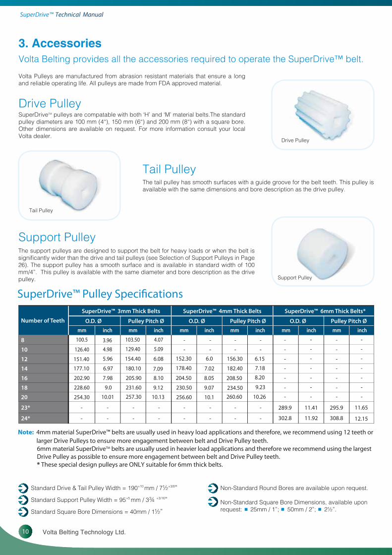
Standard Drive & Tail Pulley Width = 190+10 mm / 7½+3/8”
Standard Support Pulley Width = 95+5 mm / 3¾ +3/16”
Standard Square Bore Dimensions = 40mm / 1½”
Drive Pulley
Tail Pulley
Support Pulley
3. AccessoriesVolta Belting provides all the accessories required to operate the SuperDrive™ belt.
Drive Pulley
Tail Pulley
Support Pulley
Non-Standard Round Bores are available upon request.
Non-Standard Square Bore Dimensions, available uponrequest: 25mm / 1”; 50mm / 2”; 2½”. ▪ ▪ ▪
SuperDriveTM pulleys are compatable with both ‘H’ and ‘M’ material belts.The standard pulley diameters are 100 mm (4“), 150 mm (6“) and 200 mm (8“) with a square bore. Other dimensions are available on request. For more information consult your local Volta dealer.
Volta Pulleys are manufactured from abrasion resistant materials that ensure a long and reliable operating life. All pulleys are made from FDA approved material.
The support pulleys are designed to support the belt for heavy loads or when the belt is significantly wider than the drive and tail pulleys (see Selection of Support Pulleys in Page 26). The support pulley has a smooth surface and is available in standard width of 100 mm/4”. This pulley is available with the same diameter and bore description as the drive pulley.
The tail pulley has smooth surfaces with a guide groove for the belt teeth. This pulley is available with the same dimensions and bore description as the drive pulley.
SuperDrive™ Pulley Specifications
Number of Teeth
SuperDrive™ 3mm Thick Belts SuperDrive™ 4mm Thick Belts SuperDrive™ 6mm Thick Belts*
O.D. Ø Pulley Pitch Ø O.D. Ø Pulley Pitch Ø O.D. Ø Pulley Pitch Ø
8 -
10 -
-
-
-
-
-
-
-
-
-
-
-
-
-
-
-
-
-
-
-
-
-
-
-
-
-
-
-
-
-
-
-
-
-
-
-- - -
-
-
-
-
-
-
-
-
-
-
-
-
12
14
16
18
20
23*
24*
289.9 11.41 295.9 11.65
302.8 11.92 308.8 12.15
Note: 4mm material SuperDrive™ belts are usually used in heavy load applications and therefore, we recommend using 12 teeth orlarger Drive Pulleys to ensure more engagement between belt and Drive Pulley teeth.6mm material SuperDriveTM belts are usually used in heavier load applications and therefore we recommend using the largest Drive Pulley as possible to ensure more engagement between belt and Drive Pulley teeth.* These special design pulleys are ONLY suitable for 6mm thick belts.
11www.voltabelting.com
Square Plastic (UHMW) Locking Collar
Round Plastic (UHMW) Locking Collar
Square Metal Locking Collar
Standard bore Round Corner bore
1
2
3
Pulley bore patterns
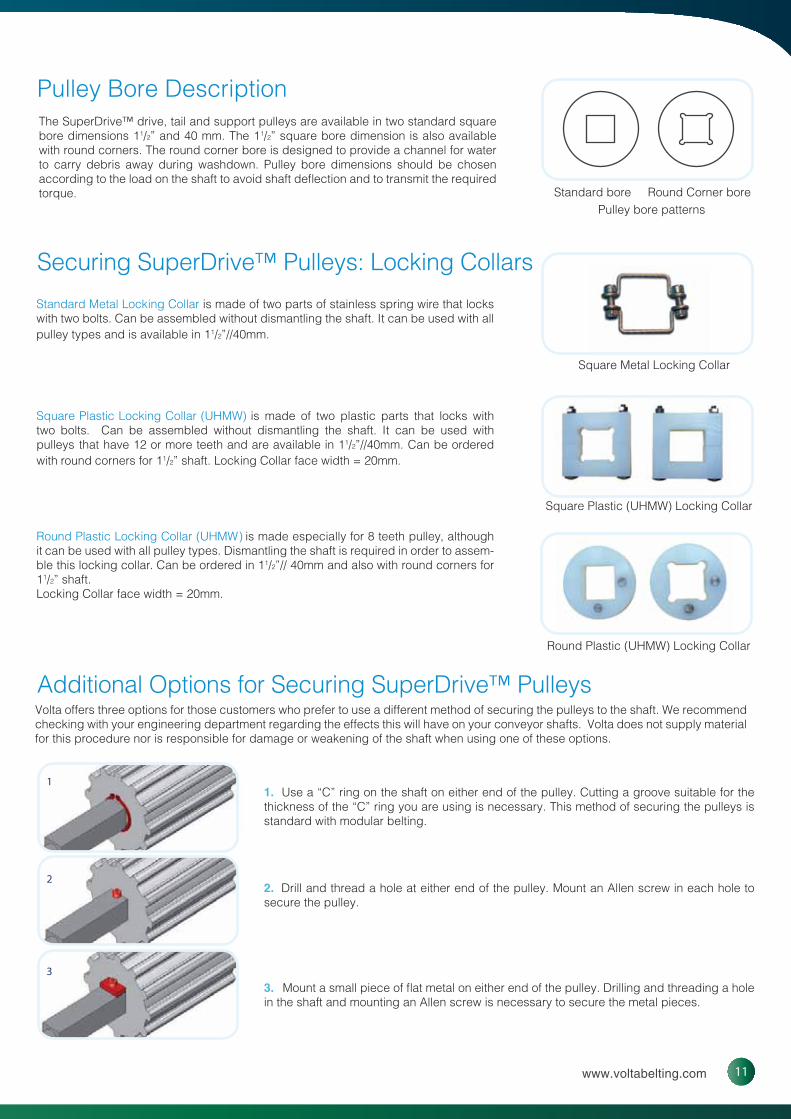
Pulley Bore Description
Securing SuperDrive™ Pulleys: Locking Collars
Additional Options for Securing SuperDrive™ Pulleys
The SuperDrive™ drive, tail and support pulleys are available in two standard square bore dimensions 11/2” and 40 mm. The 11/2” square bore dimension is also available with round corners. The round corner bore is designed to provide a channel for water to carry debris away during washdown. Pulley bore dimensions should be chosen according to the load on the shaft to avoid shaft deflection and to transmit the required torque.
Standard Metal Locking Collar is made of two parts of stainless spring wire that locks with two bolts. Can be assembled without dismantling the shaft. It can be used with all pulley types and is available in 11/2”//40mm.
Square Plastic Locking Collar (UHMW) is made of two plastic parts that locks with two bolts. Can be assembled without dismantling the shaft. It can be used with pulleys that have 12 or more teeth and are available in 11/2”//40mm. Can be ordered with round corners for 11/2” shaft. Locking Collar face width = 20mm.
Round Plastic Locking Collar (UHMW) is made especially for 8 teeth pulley, although it can be used with all pulley types. Dismantling the shaft is required in order to assem-ble this locking collar. Can be ordered in 11/2”// 40mm and also with round corners for 11/2” shaft. Locking Collar face width = 20mm.
1. Use a “C” ring on the shaft on either end of the pulley. Cutting a groove suitable for the thickness of the “C” ring you are using is necessary. This method of securing the pulleys is standard with modular belting.
2. Drill and thread a hole at either end of the pulley. Mount an Allen screw in each hole to secure the pulley.
3. Mount a small piece of flat metal on either end of the pulley. Drilling and threading a hole in the shaft and mounting an Allen screw is necessary to secure the metal pieces.
Volta offers three options for those customers who prefer to use a different method of securing the pulleys to the shaft. We recommend checking with your engineering department regarding the effects this will have on your conveyor shafts. Volta does not supply material for this procedure nor is responsible for damage or weakening of the shaft when using one of these options.

12 Volta Belting Technology Ltd.
SuperDrive™ Technical MMaanuuaal
Motorized Pulley
In the motorized pulleys, the motor, gearbox and shaft are totally enclosed within a drum motor shell. Power from the motor is transmitted through the gearbox, which is coupled to a geared rim fixed to the drum end housing.
It is especially useful on fish factory ships, meat and poultry processing lines and in the production of milk and dairy products. In these applications, the motor and gears are enclosed within the drum which makes it impervious to high pressure cleaning. This is a major benefit in food processing where hygiene is of the utmost importance. An added benefit when using our SuperDriveTM is that it creates a conveying system that is hygienic and easily cleaned, while withstanding the high pressure and temperature of water used in cleaning food processing facilities.
For a better conveyor performance, we recommend using a UHMW drum adaptor. The drawing shows two stainless steel rings which have 3 or more pins that are inserted into the drum shell from both sides. The stainless steel rings are connected by 3 bolts or more to the drum motor shell and are placed in the rings and inserted into small grooves in the drum motor shell.
The ring diameter should be less than the diameter of the pulley teeth base to release the dirt and clean the pulley.
We recommend that the thickness of the pulley teeth base is not less than 15 mm (5/8 in). The stainless steel rings can be shaped sprocket-like or similar to the shape of the teeth. Then the pins can be inserted into the teeth area of the shell.
We cooperate with several of the best known motorized pulley manufacturers to develop drum motors fitted with pulleys and teeth suitable to the SuperDriveTM conveyor belt. Please contact your local Volta belting distributor or Volta Belting for more information.

13www.voltabelting.com
4. Conveyor Construction
Classic Conveyor ConstructionThe classic conveyor construction consists of the following parts:
• Volta Drive Pulley• Slidebed made of UHMW Strips• Tail Pulley with Tension Device• Additional support pulleys depending on the belt width and the projected load (see Belt Calculations on Page 28).• Return Rollers• Snub Rollers when needed In particularly long conveyors with heavy loads we recommend using roller slide bed as shown on Page 15.
Many conveyors have a special construction that allows a complete and quick removal of the belt without using a lace.
Conveyor Construction GuidelinesSuggested Conveyor Slidebed Construction
UHMW StripsRecommended dimensions:
A. Distance between Guide Strips for the belt teeth: 85mm (3.35”)
B. Distance between Support Strips: 100-150mm (4-6”)
C. Distance of the front edge of the slide strip from the pulley depends on the cross - section of the slide strip and the slide strip supports. ‘C’ should be kept to a minimum possible distance as long as ‘X’ is at least 20mm.
D. Distance between Drive Pulley Centre and Strip Surface: half of thedrive pulley diameter.
E. Distance between Slide Bed Surface and Return Bed Surface at180° contact engagement between the belt and pulley: pulley pitch diameter(= pulley diameter + belt thickness).
F. Strips width: 25-50mm (1-2”)
G.
BB
BB
C
A
Maximum distance between the belt edges and Strip : 50mm (2”)
G
G
F
AB
14 Volta Belting Technology Ltd.
SuperDrive™ Technical MMaanuuaal
A A
Return Rollers
Standard Belt Tensioners
Quick Release Tensioner
Snub Rollers
Drawing 1
Drawing 2
Drawing 3
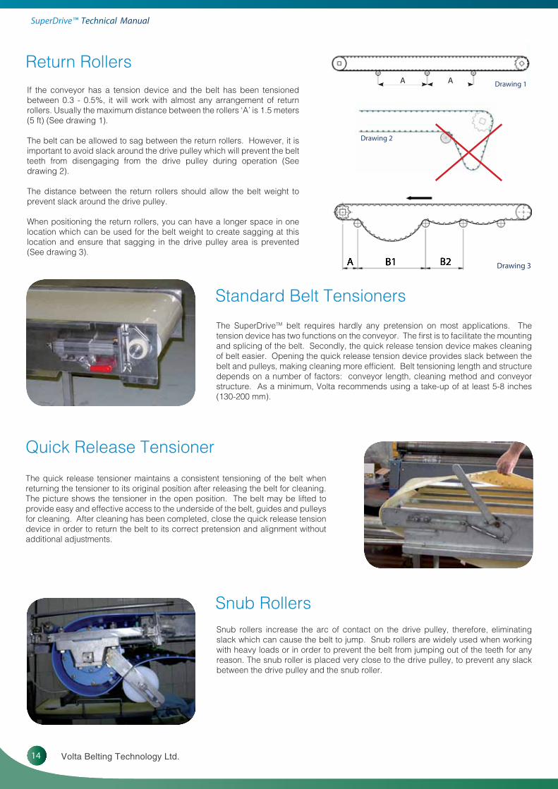
If the conveyor has a tension device and the belt has been tensioned between 0.3 - 0.5%, it will work with almost any arrangement of return rollers. Usually the maximum distance between the rollers ‘A’ is 1.5 meters(5 ft) (See drawing 1).
The belt can be allowed to sag between the return rollers. However, it is important to avoid slack around the drive pulley which will prevent the belt teeth from disengaging from the drive pulley during operation (See drawing 2).
The distance between the return rollers should allow the belt weight to prevent slack around the drive pulley.
When positioning the return rollers, you can have a longer space in one location which can be used for the belt weight to create sagging at this location and ensure that sagging in the drive pulley area is prevented (See drawing 3).
The SuperDriveTM belt requires hardly any pretension on most applications. The tension device has two functions on the conveyor. The first is to facilitate the mounting and splicing of the belt. Secondly, the quick release tension device makes cleaning of belt easier. Opening the quick release tension device provides slack between the belt and pulleys, making cleaning more efficient. Belt tensioning length and structure depends on a number of factors: conveyor length, cleaning method and conveyor structure. As a minimum, Volta recommends using a take-up of at least 5-8 inches (130-200 mm).
Snub rollers increase the arc of contact on the drive pulley, therefore, eliminating slack which can cause the belt to jump. Snub rollers are widely used when working with heavy loads or in order to prevent the belt from jumping out of the teeth for any reason. The snub roller is placed very close to the drive pulley, to prevent any slack between the drive pulley and the snub roller.
The quick release tensioner maintains a consistent tensioning of the belt when returning the tensioner to its original position after releasing the belt for cleaning. The picture shows the tensioner in the open position. The belt may be lifted to provide easy and effective access to the underside of the belt, guides and pulleys for cleaning. After cleaning has been completed, close the quick release tension device in order to return the belt to its correct pretension and alignment without additional adjustments.

15www.voltabelting.com
Conveyor RetrofitRetrofit of Conveyor with a Flat Slidebed
1. Flat SlidebedThe teeth can ride on the flat slidebed without affecting the belt operation. In this case, because of the SuperDrive™ teeth, the centre line of the belt will be slightly higher than the edges of the belt. This method is less recom-mended when using ‘M’ material belts.
2. Slidebed with a groove to accommodate SuperDrive™ teethWhen a groove is added to the slidebed the belt operation becomes smoother and more efficient. In this case the belt should be guided by its teeth in the centre groove and it should not touch the conveyor bed sidewalls.This construction is not recommended with ‘M’ belts in applications with heavy loads and long conveyors.
3. Slidebed with UHMW stripsSlidebed as seen in opposite drawing is the most highly recommended type, especially for SuperDrive™ ‘M’ material belt applications. The UHMW strips reduce the coefficient of friction between the belt and the slidebed. This increases the load that the belt is capable of carrying. In this case, it may be necessary to raise the position of the drive and tail pulleys.
Retrofit of Conveyor with a Roller Slidebed
This type of conveyor is not typical of food applications. If you wish to install a SuperDrive™ belt on a roller bed conveyor, use rollers with grooves in order to guide the teeth and allow a smooth belt operation.
Stainless Steel slidebed is least recommended especially when using SuperDrive™ ‘M’ belts.
These conveyors typically have outside walls. In this case strips are not necessary to guide the belt teeth (remember that the belt should not press against either one of the conveyor walls). Several options for retrofit are available :

16 Volta Belting Technology Ltd.
SuperDrive™ Technical MMaanuuaal
“Z” or Swanneck Conveyor Construction
UHMW Strip Bed Construction Roller Bed ConstructionFigure 1 Figure 2
The “Z” or swanneck conveyor is in relatively common use for lifting the product from a lower to an upper level.
The SuperDriveTM is ideally suited to this application for several reasons:
• The SuperDriveTM material is relatively stiff across the belt and will not bend in the middle when the belt changes from a horizontal to an angled position.• The SuperDriveTM operates without tension, therefore, eliminates problems of holding the belt in place.
The direction change (horizontal to angle) can be made as for regular belts by using a roller or a set of small rollers (see drawing below).
1. Tail Pulley2. Roller Set: Transition Horizontal to Incline3. Incline UHMW Slide Bed4. Top Roller: Transition Incline to Horizontal5. Drive Pulley. 6. Roller Set: Return transition horizontal to decline7. Return Support Roller8. Bottom Roller: Return transition decline to horizontal9. Tensioning Device for tail pulley
Figure 1 & 2 demonstrate typical Z-elevator conveyor constructions. The difference between the 2 configurations is the elevating slide belt type. In Fig. 1 a UHMW strip bed is shown and Fig 2 shows a roller slide bed. In applications with heavy loads & long conveyors it is important to use the roller slide bed type (Fig. 2) especially when using ‘M’ type belts.
In transition areas 2 + 4 – the belt rubs against the conveyor curved construction and creates a high strain area. Therefore, it is very impor-tant to use rollers at these two transition points which will minimize the strain and friction at these points.
1. Tail Pulley2. Roller Set: Transition Horizontal to Incline3. Roller Slide Bed4. Top Roller: Transition Incline to Horizontal5. Drive Pulley. 6. Roller Set: Return transition horizontal to decline7. Return Support Roller8. Bottom Roller: Return transition decline to horizontal9. Tensioning Device for tail pulley

17www.voltabelting.com
Swanneck conveyor - transition rollers/ shoe (direction change) options
Roller SetShoe Roller
Guide Typemm4 ’M‘ ™evirDrepuSmm3 ’M‘ ™evirDrepuS
Normal Flex Back Flex* Normal Flex Back Flex*
VLB/VLC-13 145mm / 5.70” 150mm / 5.90” 185mm / 7.28” 200mm / 7.87”
VLB/VLC-17 177.5mm / 7” 175mm / 6.89” 217.5mm / 8.56” 225mm / 8.85”
CLB/CLC-13 124mm / 4.88” 140mm / 5.51” 164mm / 6.45” 190mm / 7.48”
CLB/CLC-17 146mm / 5.74” 160mm / 6.30” 186mm / 7.32” 210mm / 8.26”
VSB/VSC-13 125.5mm / 4.94” 135mm / 5.31” 165.5mm / 6.50” 185mm / 7.28”
VSB/VSC-17 145mm / 5.70” 150mm / 5.90” 185mm / 7.28” 200mm / 7.87”
CSB/CSC-13 110.8mm / 3.96” 128mm / 5.04” 150.8mm / 5.93” 178mm / 7”
CSB/CSC-17 124mm / 4.88” 140mm / 5.51” 164mm / 6.45” 190mm / 7.48”
Note:Note: Contact your local distributor for further details regarding the 6mm thick SuperDrive™ belt.
* Back flex location can be seen in positions 2 and 6 on Figure 1 & 2 shown on page 16.
Minimum pulley Specifications for SuperDrive™ belt with two side guides
There are 3 typical options for the transition areas.
• The belt curve should be the maximum possible size and not less than the minimum pulley diameter of the belt + fabrications. In principle, the bigger the curve, the better. It is easiest to apply the roller set to larger curves.
• Do not use the shoe option with ‘M’ material belts, heavy loads or long conveyors. This type is least recommended.
• For belts 600mm or wider we recommend using guides on both upper edge sides of the belt. The belt guides go through the v-pulleys in the transition section to hold the belt (see the picture). This is the most recommended method.
• When using wide belts, it is very important to support the belt on the return side. Using cleats may cause problems and you may have to make a center gap in the cleat to enable supporting the belt.
18 Volta Belting Technology Ltd.
SuperDrive™ Technical MMaanuuaal
Trough Bed Construction
Transition Length
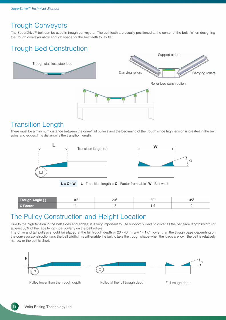
L - Transition length = C - Factor from table* W - Belt width L = C * W
Trough Angle (�) 10° 20° 30° 45°
C Factor 1 1.5 1.5 2
Trough Conveyors
The Pulley Construction and Height Location
The SuperDriveTM belt can be used in trough conveyors. The belt teeth are usually positioned at the center of the belt. When designing the trough conveyor allow enough space for the belt teeth to lay flat.
Trough stainless steel bed
Support strips
Carrying rollers
Roller bed construction
Full trough depthPulley at the full trough depthPulley lower than the trough depth
Carrying rollers
There must be a minimum distance between the drive/ tail pulleys and the beginning of the trough since high tension is created in the belt sides and edges.This distance is the transition length.
Due to the high tension in the belt sides and edges, it is very important to use support pulleys to cover all the belt face length (width) or at least 80% of the face length, particularly on the belt edges.The drive and tail pulleys should be placed at the full trough depth or 20 - 40 mm//¾ “ - 1½” lower than the trough base depending on the conveyor construction and the belt width.This will enable the belt to take the trough shape when the loads are low, the belt is relatively narrow or the belt is short.
H α
Transition length (L) L
α
w

19www.voltabelting.com
Allowed belt trough angle - FHW- 3 SD and FHB-3 SDBelt Width
300 mm/12” 400 mm/16” 500 mm/20”� 600 mm/24”Trough Angle (�)
10° No Yes Yes Yes
20° No Yes Yes Yes
30° No Yes Yes Yes
45° ***oN
Note: * When loaded, the belt will take the trough shape. Note: Discuss trough angle with your local distributor when choosing a thicker SuperDrive™ belt.
Note: Discuss trough angle with your local distributor when choosing thicker SuperDrive™ belt.
Allowed belt trough angle - FMW- 3 SD and FMB-3 SDBelt Width
300 mm/12” 400 mm/16” 500 mm/20”� 600 mm/24”Trough Angle (�)
10° * Yes Yes Yes
20° * Yes Yes Yes
30° * Yes Yes Yes
45° seYseY**
Construction of Trough Conveyor when Using SuperDriveTM Belt with Two Rows of Teeth
Trough stainless steel bed for belt with two rows of teeth. UHMW bed for belt with two rows of teeth.
Belt TensionThe belt used on a trough conveyor must have a tension of 0.3 - 0.5% for the belt to take the trough shape.
You may also use a side shoe to form the trough shape in the belt; in this case, the belt must be supported by the trough bed. The side shoe should only be used in short sections. At this side shoe point, the belt must be supported with an underside support piece that is longer than the side shoe piece.
The same principle as in the belt with one row of teeth should be taken into consideration when strips are used to support the belt. It is important to leave a gap between the belt teeth and the nearest strip to the center side (B) to enable the belt to take the trough shape. The belt can be guided by the strips on the teeth closest to the outer side (A). When adding UHMW strips on an existing frame (see figure above), the strips should be at least 10 mm (3/8”) high.

20 Volta Belting Technology Ltd.
SuperDrive™ Technical MMaanuuaal
Tail Pulley Type
Snub Rollers
Tail Pulley Type
Smooth Back-bend Pulley Drive Pulley
Removing the Belt for Cleaning
Center Drive Conveyor
This conveyor is used in two typical applications:
Conveyor Construction for quick dismounting of the belt and telescoping supports to hold the belt
• One option is when the drive pulley is large and tail pulleys can be much smaller within the limitations of the minimum pulley diameter of the base belt making the conveyor most suitable for tight transition of products. Only one snub roller can be used. In many cases only one snub roller is used by positioning it tightly against the drive pulley.
• Another option is when the conveyor works in two directions. In this case you would need two snub rollers to ensure smooth working.To prevent slippage and jumping the belt must be tensioned up to 0.5%. In most cases, snub rollers are placed both before and after the drive pulley, positioned tightly against the drive pulleys on both sides. This ensures smooth operation when the belt is running in both directions.
There are a number of options in the conveyor construction that allow the belt to be removed from the conveyor without being opened.
• Quick Release Tensioner - This device permits the release of belt tension without losing belt alignment (Page 14).In some conveyors the telescoping supports are used. During normal operation of the conveyor, the supports are flush with the sides of the conveyor. During cleaning or maintenance, the supports are pulled out and are in a position to hold the conveyor belt during cleaning and maintenance (see drawing).• The Hinge Lace or Metal Lace can be used to open the belt for cleaning and maintenance (Page 22).

21www.voltabelting.com
FBW Welding Kit
FT electrode Welding kit
5. Splicing the SuperDrive™
FT - Electrode Welding Kit
FBW Flat Butt Welding Tool
The SuperDrive™ conveyor belt is extruded with a series of teeth as an integral part of the belt. These teeth are designed to mesh with the teeth on the SuperDrive™ drive pulley. To ensure efficient performance, it is necessary to maintain the spacing between the teeth in the region of the weld.
We recommend using Volta Tools for this procedure. These tools are designed for use with all our belts and materials. They are also designed to maintain the correct spacing between the teeth on the SuperDrive™ belt.
The FT Welding System is a tool for electrode welded endless making highly suitable for Volta flat belts and SuperDrive™, DualDrive and DualDrive SP. The FT Welding System uses a router to cut the angle on the belt edges and to trim the weld on completion. The weld is carried out by using a Leister Hot Air Gun and Volta electrodes. When joining up to 2mm thick belts, use the 7mm section electrode and for a belt thicker than 2mm, the 9mm section electrode is used. This tool is supplied with a built-in adaptor for welding SuperDrive™ belts. The FT tool is capable of joining belts up to a width of 1500mm.
The FBW System was created to butt-weld flat belts making them endless. The FBW Welding System can be used for Super-Drive™, DualDrive, DualDrive SP and special textured top flat belts. The FBW tool is capable of joining belts up to a width of 2100mm.

22 Volta Belting Technology Ltd.
SuperDrive™ Technical MMaanuuaal
Figure 5a: Tooth pattern after closing the SuperDrive™ belt with lace
Figure 5b: Shows the correct spacing between teeth with one missing tooth
Cut and scrapped
Metal lace are mounted on these surfaces
Metal Lace
Note: The spacing at the splice can be reduced by up to 2-3 mm without adversely affecting belt operation. However, the distance between the teeth should never be increased.
With some lacing products, such as the Alligator brand model RS62 and RS125, it may be necessary to remove one tooth completely. For these products, it will be necessary to cut each end of the belt at the base of a tooth (Figure 5a). After mounting the Alligator brand metal lacing, the belt will have a gap of one tooth (Figure 5b). The loss of one tooth will not affect the operation of the belt. We do not recom-mend using this method when using pulleys of 12 teeth or less.
There are occasions when it may be necessary to splice the SuperDriveTM belt using lace.
When working with lace, it is important that you work according to the recommendations of the lace manufacturer.
When using lace for splicing the SuperDriveTM belt, the Pull Force calculations provided by Volta are not applicable.
The distance between the teeth at the splice must be the same as the distance between the teeth on the rest of the belt.
Cut
Scrap
Scrap

23www.voltabelting.com
Closing belt with Universal Lace
Plastic Hinge Lace
Hinge Lace BenefitsEasy Open-Close Technique
Reduced Maintenance Downtime
Plastic Hinge Lace SpecificationsU-BML atloVU-WML atloV
Description pirts dehtoot talFpirts dehtoot talF
Material eulb ,BM atloVegieb ,WM atloV
Hardness A59A59
Working Temp Range -20°C to 60°C/ -5°F to 140°F -20°C to 60°C/ -5°F to 140°F
Dimensions ni 36.0 x ni 2.0 - mm 61 x 5ni 36.0 x ni 2.0 - mm 61 x 5
Max Length tf 01 - m 50.3tf 01 - m 50.3
Max Pull Force ni/bl 8.61 - mc/gk 3ni/bl 8.61 - mc/gk 3
Minimum PulleyNormal Flex with SD 3mm
80 mm/ 31/8 3 /mm 08.ni 1/8 in.
Minimum PulleyBack Flex with SD 3mm .ni 4 /mm 001.ni 4 /mm 001
Hinge Pin Stainless Steel: 1.65 mm / FDA approved
The Plastic Hinge Lace allows you to easily open the belt by taking the hinge pin out, clean or service the conveyor, reinstall the belt and close the lace with a new pin. The Plastic Hinge Lace is made of Volta homogeneous food approved materials and is compatible with Volta M family product belts. Volta belts are renowned for their homogeneous and hygienic characteristics and, therefore, they do not require opening and closing on a regular basis - unlike modular belts.
We recommend using the Universal Lace only when absolutely necessary. Make sure that the conveyor pulleys fully support the entire face length of the belt or al least 80% of the face length. Note that the maximum allowed pull force for the lace (per cm/ inch.) is lower than the allowed pull force of the belt (per cm/ inch.). Therefore, check that the calculated pull force of your belt is lower than the maximum allowed pull force of the lace.
The fastening structure allows you to easily open the Plastic Hinge Lace by removing the hinge pin from the lace. After setting up the belt on the conveyor, fasten the lace and close it by inserting a new hinge pin into the slit and crimp up the pin ends.
Since Volta belts are extremely hygienic, you don’t have to regularly install and uninstall your belt for cleaning. In cases where belt disman-tling is necessary, Universal Lace provides you with the best solution. Why? Volta Universal Lace will not tear off from the belt, since it is welded onto your belt and is made of the same homogeneous material.
5
L
16
24 Volta Belting Technology Ltd.
SuperDrive™ Technical MMaanuuaal
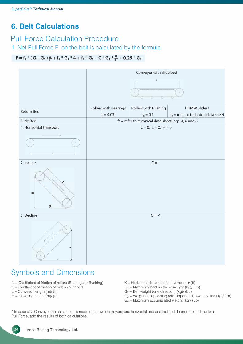
F = fS * ( G1+G2 ) + fR * G2 * + fR * G3 + C * G1 * + 0.25 * G4XL
HL
XL
6. Belt Calculations
Pull Force Calculation Procedure
Symbols and Dimensions
* In case of Z Conveyor the calculation is made up of two conveyors, one horizontal and one inclined. In order to find the total Pull Force, add the results of both calculations.
Conveyor with slide bed
Return BedRollers with Bearings
fR = 0.03
Rollers with Bushing
fR = 0.1
UHMW Sliders
fR = refer to technical data sheet
Slide Bed fs = refer to technical data sheet, pgs. 4, 6 and 8
1. Horizontal transport C = 0; L = X; H = 0
2. Incline C = 1
3. Decline C = -1
1. Net Pull Force F on the belt is calculated by the formula
fR = Coefficient of friction of rollers (Bearings or Bushing)fS = Coefficient of friction of belt on slidebedL = Conveyor length (m)/ (ft)H = Elevating height (m)/ (ft)
X = Horizontal distance of conveyor (m)/ (ft)G1 = Maximum load on the conveyor (kg)/ (Lb)G2 = Belt weight (one direction) (kg)/ (Lb)G3 = Weight of supporting rolls-upper and lower section (kg)/ (Lb) G4 = Maximum accumulated weight (kg)/ (Lb)

25www.voltabelting.com
Fa = Fmax * K
Fa = Allowed pull force
Fmax = Maximum pull force allowed for the belt (Technical Data table, pgs. 4, 6 and 8)
K= Factor from Table 6a
4. Verify that the selected belt can carry the calculated pull force
stnemmoCrotcaF KhseM ni hteeT
6 or more 1 180° arc of contact at standard 150 mm/6” pulley
5 0.8
4 0.6 180° arc of contact at standard 100 mm/4” pulley
2. Pull Force per unit belt widthDivide the Calculated Pull Force from Step 1 by the belt width (cm or inch.) and record the answer.
3. Determine allowed pull force and pulley diameterPulley diameter affects the maximum allowable pull force (Fa). To determine the Allowable Pull Force (Fa), find the number of meshed teeth in the left hand column of Table 6a. If the number of meshed teeth is less than 6, multiply the Maximum Pull Force (Table 2.1, Page 4 or Table 2.3, Page 6 or Table 2.5 page 8) by K Factor below.
Compare the answer in step 2 to the Maximum Allowable Pull Force. If the Calculated Pull Force in Step 2, is less than or equal to Maximum Allowable Pull Force (Fa), then the selected belt is suitable for the application. You should continue with Step 5 to select the correct combination of Drive/Tail and Support Pulleys. If the Calculated Pull Force in Step 2 is greater than maximum Allowable Pull Force in Step 3, you must change one of the following parameters:• Increase the belt width.• Change the slidebed to reduce the coefficient of friction. Volta recommends using UHMW strips.• Add a snub roller to increase the arc of contact (to increase the number of meshed teeth).• Choose a larger diameter Pulley (to increase the number of meshed teeth).• Reduce the load on the belt.
Table 6a: K Factor
For belts with one row of teeth add support pulleys in pairs.Tables 6b and 6c give the different pulley combinations based on the Pull Force. Locate the Calculated Pull Force from Step 1 in Tables 6b and 6c. The row heading indicates the pulley combination you need for the conveyor drive and tail shafts. Volta recom-mends using support pulleys for any belt 600mm/24” or wider regardless of the load weight.

26 Volta Belting Technology Ltd.
SuperDrive™ Technical MMaanuuaal
Table 6b: Selection of Support Pulleys for FMW/ FMB-3 SD and FMW/ FMB-4 SD
FMW/ FMB-3 SD FMW/ FMB-4 SD
Required Pulley Combination Pull Force (kg)up to
Pull Force (lb)up to
Pull Force (kg)up to
Pull Force (lb)up to
783671403831yelluP evirD
937633875362syellup troppus 2 htiw yelluP evirD
1901694458883syellup troppus 4 htiw yelluP evirD
34416560311315syellup troppus 6 htiw yelluP evirD
For Two Rows of Teeth
2 Drive Pulleys (one for each row of teeth) 276 608 352 774
6710863126:dda yellup troppus hcae roF
Table 6c: Selection of Support Pulleys for FHW/ FHB-3 SD and FHW/ FHB-4 SD
FHW/ FHB-3 SD FHW/ FHB-4 SD
Required Pulley Combination Pull Force (kg)up to
Pull Force (lb)up to kg up to lb up to
475162844302yelluP evirD
079144657343syellup troppus 2 htiw yelluP evirD
66311265601384syellup troppus 4 htiw yelluP evirD
26711084731326syellup troppus 6 htiw yelluP evirD
For Two Rows of Teeth
2 Drive Pulleys (one for each row of teeth) 406 896 522 1148
Each support pulley can be loaded up to: 70 154 90 198
For belts with two rows of teeth determine the number of Support Pulleys as follows5.1. If the Calculated Pull Force from Step 1 is less than the values shown in Table 6b for SD-M or Table 6c for SD-H for the Pull Force of a Standard Pulley (one for each row of teeth), you will need two Drive Pulleys without Support Pulleys. Nevertheless, Volta recommends the use of one Support Pulley mounted between the two Drive Pulleys.
For a belt wider than 1200mm we recommend using at least 3 support pulleys regardless of load (one support between two rows of teeth and one on either end side of the teeth).
5.2. If the Calculated Pull Force in Step 1 is greater than the value shown in Table 6b for SD-M or Table 6c for SD-H:
5.2.1. Subtract the value in Table 6b or 6c from the calculated Pull Force (For example, for “M” material we substract 276 kg / 608 lbs).
5.2.2. Divide the answer by 62 kg/136 lbs (for “M” material, Table 6b) and round up the given value. This gives the number of Support Pulleys needed to meet the Pull Force requirements.
For example, if the Pull Force is 320 kg/ 704 lbs. for a SD ‘M’ belt with two rows of teeth, then the number of support pulleys that you need is calculated as follows:
Metric Calculation English Calculation(320 - 276) /62 = 0.7 and round up to 1 (704 - 608) /136 = 0.7 and round up to 1
You will need one support pulley for each one of your conveyor drive and tail shafts. After selecting the number of Support Pulleys required, add the lengths of all the Pulleys (Drive and Support or Tail and Support)together and make sure that the total length of pulleys is not larger than the width of the belt.
For belts with one row of teeth add support pulleys in pairs.Tables 6b and 6c give the different pulley combinations based on the Pull Force. Locate the Calculated Pull Force from Step 1 in Tables 6b and 6c. The row heading indicates the pulley combination you need for the conveyor drive and tail shafts. Volta recommends using support pulleys for any belt 600mm/24” or wider regardless of the load weight.
5. Determine the number of support pulleys required
Discuss support pulleys with your local distributor when choosing thicker SuperDrive™ belt.
Note: Contact your local distributor for further details regarding the 6mm thick SuperDrive™ belt.

27www.voltabelting.com
6.2a
6.2b
6.2c
6.2d
Installation and Positioning of Support Pulleys
• Volta recommends using support pulleys for any belt 600 mm/ 24” or wider regardless of the load.• For belts with two rows of teeth, we recommend including at least one support pulley between the two drive pulleys. • For a belt wider than 1200mm we recommend using at least 3 support pulleys regardless of load (one support between two rows of teeth and one on either end side of the teeth).• Support pulleys should be added according to the load to be carried on the belt and the belt width. The support pulleys should be positioned to remove any depressions in the belt surface.
The figures below show how to arrange the support pulleys in the right position.
Figure 6.2a shows a depression between the two drive pulleys. In this situation, install at least one support pulley between the two drive pulleys as shown in Figure 6.2b.
Figure 6.2c shows the belt with support pulley between the drive pulleys but with the ends of the belt left unsupported.
Figure 6.2d shows the installation of support pulleys under each belt edge. The support pulleys should be positioned symmetrically.

28 Volta Belting Technology Ltd.
SuperDrive™ Technical MMaanuuaal
Conveyor Conditions
sbl 03gk 6.31thgieW egakcaP
Maximum number of packages on the belt 30 30
.tf 05m 2.51)L( htgneL royevnoC
.tf 48.9m 3)H( thgieH gniyevnoC
Converyor Horizontal Distance (X) 14.9 m 48.8 ft.
Weight of Return Rollers 4.5 kg 10 lbs
Number of Return Rollers 6 6
”6mm 251retemaiD yelluP
Number of Teeth in Mesh 6 6
00thgieW detalumuccA
1. Calculate the Maximum Pull Force
F=fs*(G1+G2)*X/L+fr*G2*X/L+fr*G3+C*G1*H/L+0.25*G4
hsilgnE cirteM
8.84=X 9.41=X
48.9=H3=H
05=L2.51=L
)debedils leets sselniats( 4.0 = sf )debedils leets sselniats( 4.0 = sf
1.0 = rf 1.0 = rf
sbl 009=03*03 =1Ggk 804=6.31*03 =1G
G2= (3.6*0.45*15.2)+(0.180*15.2)=27.4 kg G2=0.74*(18/12)*50+(0.121*50)=61.5 lbs
sbl 06=01*6 =3Ggk 72=5.4*6 =3G
0 =4G 0 =4G
F=0.4*(408+27.4)*14.9/15.2+0.1*27.4*14.9/15.2+0.1*27+1*48*3/15.2+0.25*0
F=0.4*(900+61.5)*48.8/50+0.1*61.5*48.8/50+0.1*60+1*900*9.84/50+0.25*0
sbl 5.485=F gk 6.652=F
Calculation ExampleA Stainless Steel slidebed conveyor that elevates meat packages. Check if the 450 mm (18”.) FHB3-SD belt is suitable for the applica-tion and choose the pulley set (drive, tail and support pulleys) and the pulley diameter.
2. Calculate the Pull Force per unit width of belt
256.6/45 = 5.7 kg/cm or 584.5/18 = 32.5 lbs/inch.
3. Determine Allowable Pull Force and pulley diameter
Fa=Fmax * K
Fmax = 7 kg/cm (39.2 lb/in.) - see Maximum Pull Force in Technical Data on Page 4K = 1 (180° arc of contact at standard 15 0 mm/6 in. pulley)

29www.voltabelting.com
4. Verify that the Selected Belts can Carry the Calculated Pull Force
The Pull Force per unit width of belt, 5.7 kg/cm (32.5 lbs/ft) is less than the allowable Pull Force for 6 or more teeth in mesh. Therefore you can use 150 mm (6”) pulleys with 180o arc of contact.
If you require a 100 mm (4”) pulley for design reasons, calculate as follows:
Fa=7*0.6=4.2 kg/cm or Fa=39.2*0.6=23.5 lb/in. (k = 0.6 for 4 teeth in mesh)
The allowable Pull Force 4.2 kg/cm (23.5 lb/inch.) is less than the application requirements 5.7 kg/cm (32.5 lb/inch). You must change one of the parameters listed in Step 4, Page 25. For example, if you change the slidebed to UHMW strips, the coefficient of friction will be 0.2 and therefore, the Calculated Pull Force from Step 1 will be 171.3 kg (377.6 lbs). The Pull Force per unit width of belt will be:
171.3/45 = 3.8 kg/cm or 377.6/18 = 21 lbs/inch.
This change brings the Pull Force per unit width below 4.2 kg/cm (23.5 lbs/ft). So you can use a 100 mm (4”) pulley.
5. Determine Support Pulley Requirements
The calculated pull force is 256.6 kg (584.5 lbs) and the Pull Force for a Standard Pulley without supports is 203 kg (448 lbs.) as shown in Table 6b, Page 27. Therefore we must use the standard Drive Pulley with 2 Support Pulleys.
This arrangement can take up to 343 kg (756 lbs.) of Pull Force.The length of the drive pulley and two support pulleys is shorter than the belt.
200 + 2 * 100 = 400mm 8 + 2 * 4 = 16 inch.And the belt is: 450 mm 18 inch.
30 Volta Belting Technology Ltd.
SuperDrive™ Technical MMaanuuaal
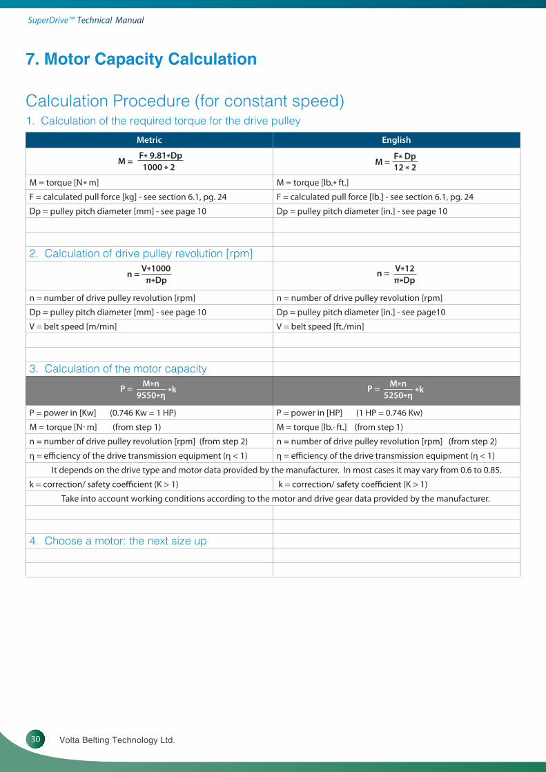
Calculation Procedure (for constant speed) 1. Calculation of the required torque for the drive pulley
7. Motor Capacity Calculation
hsilgnEcirteM
F* 9.81*Dp1000 * 2
M = F* Dp12 * 2M =
M = torque [N * m] M = torque [lb. * ft.]
F = calculated pull force [kg] - see section 6.1, pg. 24 F = calculated pull force [lb.] - see section 6.1, pg. 24
Dp = pulley pitch diameter [mm] - see page 10 Dp = pulley pitch diameter [in.] - see page 10
2. Calculation of drive pulley revolution [rpm]V*1000
π*Dpn =
V*12π*Dp
n =
n = number of drive pulley revolution [rpm] n = number of drive pulley revolution [rpm]
Dp = pulley pitch diameter [mm] - see page 10 Dp = pulley pitch diameter [in.] - see page10
V = belt speed [m/min] V = belt speed [ft./min]
3. Calculation of the motor capacityM*n
9550*ηP = *k
M*n5250*η
P = *k
P = power in [Kw] (0.746 Kw = 1 HP) P = power in [HP] (1 HP = 0.746 Kw)
M = torque [N . m] (from step 1) M = torque [lb. . ft.] (from step 1)
n = number of drive pulley revolution [rpm] (from step 2) n = number of drive pulley revolution [rpm] (from step 2)
η = e�ciency of the drive transmission equipment (η < 1) η = e�ciency of the drive transmission equipment (η < 1)
It depends on the drive type and motor data provided by the manufacturer. In most cases it may vary from 0.6 to 0.85.
k = correction/ safety coe�cient (K > 1) k = correction/ safety coe�cient (K > 1)
Take into account working conditions according to the motor and drive gear data provided by the manufacturer.
4. Choose a motor: the next size up

31www.voltabelting.com
8. Frequently Asked Questions
How much pretension is required on the SuperDrive™ for best operation?The SuperDrive™ can work with little or no pretension (in most cases you probably could get away with no pretension at all). In spite of this we recommend the installation of a tension device. The maximum pretension needed should be no more than 0.5%.
If the SuperDrive™ doesn’t require pretension, why do we need a tension device (take-up)?As stated above, the SuperDrive™ requires hardly any pretension on most applications. The tension device has two functions on the conveyor. The first is to facilitate the mounting and splicing of the belt. Secondly, the quick release tension device makes the conveyor cleaning easier. Opening the quick release tension device provides slack between the belt and the pulleys to make cleaning more efficient. At the conclusion of cleaning, closing the quick release tension device returns the belt to its correct pretension and alignment without additional adjustments.
What is the recommended length of the take-up? This depends on a number of factors of the application including: length of the conveyor, method of cleaning, structure of the conveyor. As a minimum Volta recommends using a take-up of at least 5-8 inches (130 - 200 mm).
How do I calculate the correct belt length for the SuperDrive™?The belt length for the SuperDrive™ is calculated the same as for any conveyor belt with one exception. With standard flat belting you first reduce the distance between the shafts to their minimum. Then measure the distance between the shafts and add ½ the circumfer-ence of the drive pulley and ½ the circumference of the tail pulley. Errors in splicing/welding are corrected by cutting a few millimeters from the belt and resplicing/rewelding. With the SuperDrive™, an error in welding will necessitate removing two teeth from the belt (approximately 80 mm / 3.14”) in order to maintain the correct spacing between the teeth. For this reason, when measuring the conveyor belt length, the take-up should be extended to ¾ of its maximum position and then the distance should be measured between the shafts. This will leave sufficient room for applying pretension if required. You should be aware that when you calculate the belt length it is an approximate calculation because the length of the belt depends on the conveyor construction and the ability to close the belt on the conveyor, therefore, it is very important to take measurements on-site.
How do I clean the SuperDrive™?The SuperDrive™ should be cleaned in accordance with standard Volta instructions. A copy of Volta’s cleaning instructions is available from your local Volta representative.
What is the maximum water temperature that can be used to clean the SuperDrive™? The water temperature should not exceed 80oC (176oF).
Can cleats be fabricated on the SuperDrive™ belt?Yes they can. See technical data on pages 5, 7 and 9.
Will the SuperDrive™ develop edge waves?The waves at the edge of the belt are typically caused by an off-tracking condition where the belt edge comes into contact with the conveyor’s frame. Because the SuperDrive™ eliminates off-tracking, you should experience no waves on the edges of the belt. The condition may also be caused by certain maintenance practices. For example, the use of broom handles to hold the belt up during cleaning with hot water. If these are left while the belt cools, waves could remain where the broom handles were.
What is the maximum offset from the center line allowed for the drive pulley?It is preferred that the SuperDrive™ operate with the drive pulley in the center of the conveyor to ensure correct and efficient operation.

Think Positive! Think SuperDriveTM!
SD™ Drive & Support pulley
SuperDrive™working under water
Perforated SD™ belt with cleats
On site welding
SD™- LT Low Temperature "Z" or Swanneck Conveyor Trough conveyor
SD™ Tail pulley SD™ Drive pulley
Copyright©2010 Volta Belting Technology Ltd.CAT200EN00 - Ver. D - January 2013
www.voltabelting.com
Volta Belting makes no warranty with respect to any of its products for a particular purpose. See Volta General Terms and Conditions. Copyright©2012 Volta Belting Technology Ltd.
Corporate HeadquartersSales and [email protected]
USATel: +1 973 276 7905Fax: +1 973 276 7908Toll Free: 1-877-VOLTAUS
EUROPETel: +31-546-580166Fax: +31-546-579508