Embed Size (px)
Citation preview

Software & Systems ProcessEngineering Meta-Model (SPEM)
ENTERPRISE ARCHITECT
User Guide Series
Author: Sparx Systems
Date: 2022-01-07
Version: 16.0
CREATED WITH

Table of Contents
Software & Systems Process Engineering Meta-Model (SPEM) 3Getting Started 5Example Diagram 7Language Overview 9SPEM Toolbox Pages 10More Information 15
Software & Systems Process Engineering Meta-Model (SPEM) 7 January, 2022
Software & Systems Process Engineering Meta-Model(SPEM)
Create Expressive Process Meta-models for Software and Systems Engineering Projects
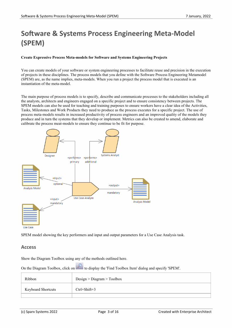
You can create models of your software or system engineering processes to facilitate reuse and precision in the executionof projects in these disciplines. The process models that you define with the Software Process Engineering Metamodel(SPEM) are, as the name implies, meta-models. When you run a project the process model that is executed is aninstantiation of the meta-model.
The main purpose of process models is to specify, describe and communicate processes to the stakeholders including allthe analysts, architects and engineers engaged on a specific project and to ensure consistency between projects. TheSPEM models can also be used for teaching and training purposes to ensure workers have a clear idea of the Activities,Tasks, Milestones and Work Products they need to produce as the process executes for a specific project. The use ofprocess meta-models results in increased productivity of process engineers and an improved quality of the models theyproduce and in turn the systems that they develop or implement. Metrics can also be created to amend, elaborate andcalibrate the process meat-models to ensure they continue to be fit for purpose.
SPEM model showing the key performers and input and output parameters for a Use Case Analysis task.
Access
Show the Diagram Toolbox using any of the methods outlined here.
On the Diagram Toolbox, click on to display the 'Find Toolbox Item' dialog and specify 'SPEM'.
Ribbon Design > Diagram > Toolbox
Keyboard Shortcuts Ctrl+Shift+3
(c) Sparx Systems 2022 Page 3 of 16 Created with Enterprise Architect
Software & Systems Process Engineering Meta-Model (SPEM) 7 January, 2022
Other Click the icon on the Diagram caption bar to display the Diagram Toolbox
SPEM Integration
Use Discussion
SPEM in EnterpriseArchitect
Developing SPEM diagrams is quick and simple, using the MDG Technology forSPEM 2.0. The SPEM facilities are provided in the form of:
A SPEM diagram type, accessed through the 'New Diagram' dialog·A set of SPEM pages in the Diagram Toolbox, providing SPEM elements·(stereotyped UML elements)
SPEM element and relationship entries in the 'Toolbox Shortcut Menu' and·Quick Linker
(c) Sparx Systems 2022 Page 4 of 16 Created with Enterprise Architect
Software & Systems Process Engineering Meta-Model (SPEM) 7 January, 2022
Getting Started
The MDG Technology for SPEM 2.0 is one of the modeling tools integrated with Enterprise Architect.
"The Software and Systems Process Engineering Metamodel (SPEM) is a process engineering meta-model as well asconceptual framework, which can provide the necessary concepts for modeling, documenting, presenting, managing,interchanging, and enacting development methods and processes. An implementation of this meta-model would betargeted at process engineers, project leads, project and program managers who are responsible for maintaining andimplementing processes for their development organizations or individual projects."
(Quoted from the Object Management Group (OMG) Software & Systems Process Engineering Meta-ModelSpecification (Version 2.0, April 01 2008))
SPEM is a Profile of UML, which uses UML as a notation and takes an object-oriented approach. To accommodateUML 2, the SPEM specification was upgraded to 2.0 in April 2008. SPEM 2.0 focuses on providing the additionalinformation structures that you require for processes modeled with UML 2 Activities or BPMN/BPDM, to describe anactual development process.
Selecting the Perspective
Enterprise Architect partitions the tool's extensive features into Perspectives, which ensures that you can focus on aspecific task and work with the tools you need without the distraction of other features. To work with the Software &Systems Process Engineering Meta-Model you first need to select the Perspective:
<perspective name> > Management > SPEM
Setting the Perspective ensures that the SPEM diagrams, their tool boxes and other features of the Perspective will beavailable by default.
Example Diagram
An example diagram provides a visual introduction to the topic and allows you to see some of the important elementsand connectors that are created in specifying or describing a Software or System Engineering method or processincluding: Process Activities, Milestones, Team Profiles, Work Product Definitions, Steps, Tool and Task DefinitionsGuidance Metrics and more.
Language Overview
This topic introduces you to the main concepts of the language including its structure, architecture and the elements andconnectors that are used to create SPEM models.
Toolbox Pages
The toolboxes contain the palette of elements and connectors that can be used to create software or system processengineering metamodels. When you create a process metamodel you will use these items to create drawing of the processyou wish to define.
More Information
This section provides useful links to other topics and resources that you might find useful when working with the
(c) Sparx Systems 2022 Page 5 of 16 Created with Enterprise Architect

Software & Systems Process Engineering Meta-Model (SPEM) 7 January, 2022
Software & Systems Process Engineering Meta-Model tool features.
(c) Sparx Systems 2022 Page 6 of 16 Created with Enterprise Architect
Software & Systems Process Engineering Meta-Model (SPEM) 7 January, 2022
Example Diagram
You can model the development processes underpinning software and business process modeling using SPEM diagrams,and the wide range of specialized elements and connectors provided in the 'SPEM' pages of the Diagram Toolbox.
Example Diagram
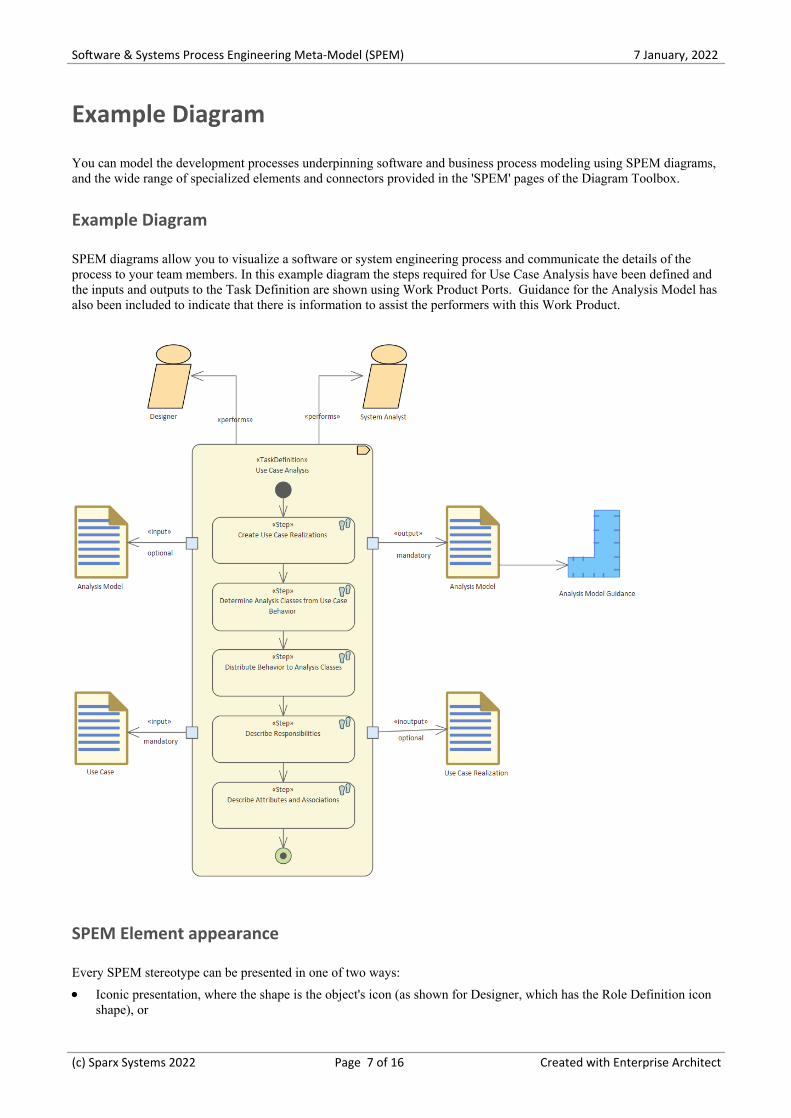
SPEM diagrams allow you to visualize a software or system engineering process and communicate the details of theprocess to your team members. In this example diagram the steps required for Use Case Analysis have been defined andthe inputs and outputs to the Task Definition are shown using Work Product Ports. Guidance for the Analysis Model hasalso been included to indicate that there is information to assist the performers with this Work Product.
SPEM Element appearance
Every SPEM stereotype can be presented in one of two ways:
Iconic presentation, where the shape is the object's icon (as shown for Designer, which has the Role Definition icon·shape), or
(c) Sparx Systems 2022 Page 7 of 16 Created with Enterprise Architect
Software & Systems Process Engineering Meta-Model (SPEM) 7 January, 2022
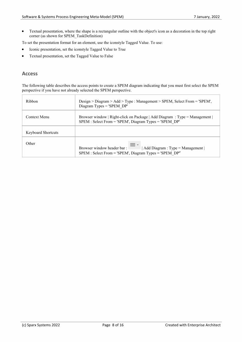
Textual presentation, where the shape is a rectangular outline with the object's icon as a decoration in the top right·corner (as shown for SPEM_TaskDefinition)
To set the presentation format for an element, use the iconstyle Tagged Value. To use:
Iconic presentation, set the iconstyle Tagged Value to True·Textual presentation, set the Tagged Value to False·
Access
The following table describes the access points to create a SPEM diagram indicating that you must first select the SPEMperspective if you have not already selected the SPEM perspective.
Ribbon Design > Diagram > Add > Type : Management > SPEM, Select From = 'SPEM',Diagram Types = 'SPEM_DP'
Context Menu Browser window | Right-click on Package | Add Diagram : Type = Management |SPEM : Select From = 'SPEM', Diagram Types = 'SPEM_DP'
Keyboard Shortcuts
OtherBrowser window header bar : | Add Diagram : Type = Management |SPEM : Select From = 'SPEM', Diagram Types = 'SPEM_DP''
(c) Sparx Systems 2022 Page 8 of 16 Created with Enterprise Architect
Software & Systems Process Engineering Meta-Model (SPEM) 7 January, 2022
Language Overview
You will use the Software & Systems Process Engineering Meta-Model to define software and systems developmentprocesses and the components that they are made up of including: Activities, Tasks, Milestones and Work Products. Thescope of SPEM is intentionally limited to the minimal elements necessary to define any software and systemsdevelopment process. Features for particular development domains or disciplines (e.g., project management, analysis)have been deliberately excluded. The focus of SPEM is squarely set on development projects with the goal to create afacility useful for a large range of development methods and processes of different styles, cultural backgrounds, levels offormalism, life-cycle models, and communities.
SPEM is not a generic but rather a highly flexible process modeling language, and does not attempt to provide its ownbehavior modeling concepts. The language rather defines the ability for the implementor to choose the generic behaviormodeling approach that best fits their needs. It also provides specific structures to enhance such generic behavior modelsthat are characteristic for describing development processes. SPEM defines the additional elements and informationstructures that you need for engineering processes modeled with UML 2.0 Activities or BPMN/BPDM to describe aproduction development process. The SPEM 2.0 meta-model is structured into seven main meta-model packages as
The structure partitions the model into logical units. Each unit extends the units it depends upon, and in turn providesadditional structures and capabilities to the elements defined lower down in the structure. The UML package mergemechanism is used to realize a gradual extension of the capabilities modeled unit by unit, effectively meaning the lowerpackages are used for more specialized processes.
(c) Sparx Systems 2022 Page 9 of 16 Created with Enterprise Architect
Software & Systems Process Engineering Meta-Model (SPEM) 7 January, 2022
SPEM Toolbox Pages
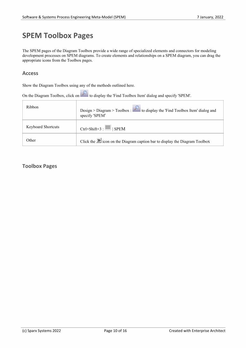
The SPEM pages of the Diagram Toolbox provide a wide range of specialized elements and connectors for modelingdevelopment processes on SPEM diagrams. To create elements and relationships on a SPEM diagram, you can drag theappropriate icons from the Toolbox pages.
Access
Show the Diagram Toolbox using any of the methods outlined here.
On the Diagram Toolbox, click on to display the 'Find Toolbox Item' dialog and specify 'SPEM'.
RibbonDesign > Diagram > Toolbox : to display the 'Find Toolbox Item' dialog andspecify 'SPEM'
Keyboard Shortcuts Ctrl+Shift+3 : | SPEM
Other Click the icon on the Diagram caption bar to display the Diagram Toolbox
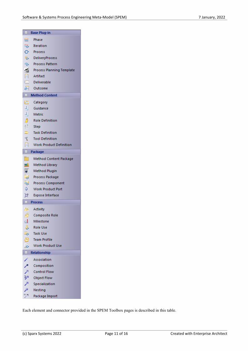
Toolbox Pages
(c) Sparx Systems 2022 Page 10 of 16 Created with Enterprise Architect
Software & Systems Process Engineering Meta-Model (SPEM) 7 January, 2022
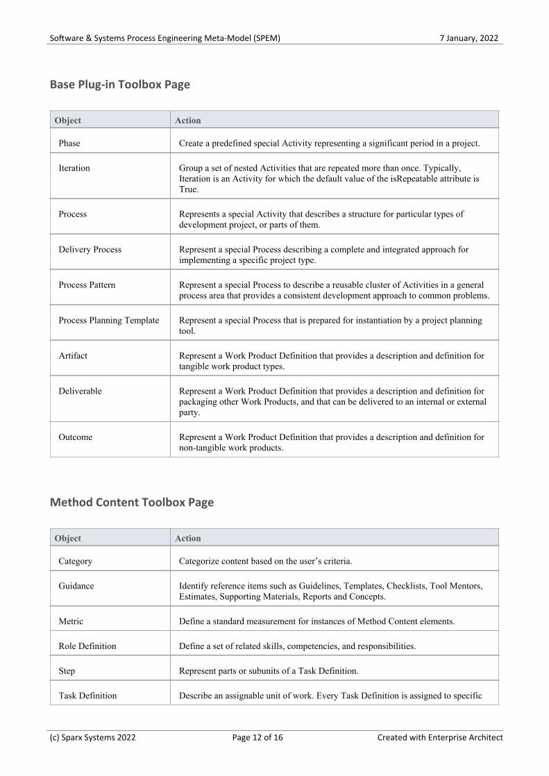
Each element and connector provided in the SPEM Toolbox pages is described in this table.
(c) Sparx Systems 2022 Page 11 of 16 Created with Enterprise Architect
Software & Systems Process Engineering Meta-Model (SPEM) 7 January, 2022
Base Plug-in Toolbox Page
Object Action
Phase Create a predefined special Activity representing a significant period in a project.
Iteration Group a set of nested Activities that are repeated more than once. Typically,Iteration is an Activity for which the default value of the isRepeatable attribute isTrue.
Process Represents a special Activity that describes a structure for particular types ofdevelopment project, or parts of them.
Delivery Process Represent a special Process describing a complete and integrated approach forimplementing a specific project type.
Process Pattern Represent a special Process to describe a reusable cluster of Activities in a generalprocess area that provides a consistent development approach to common problems.
Process Planning Template Represent a special Process that is prepared for instantiation by a project planningtool.
Artifact Represent a Work Product Definition that provides a description and definition fortangible work product types.
Deliverable Represent a Work Product Definition that provides a description and definition forpackaging other Work Products, and that can be delivered to an internal or externalparty.
Outcome Represent a Work Product Definition that provides a description and definition fornon-tangible work products.
Method Content Toolbox Page
Object Action
Category Categorize content based on the user’s criteria.
Guidance Identify reference items such as Guidelines, Templates, Checklists, Tool Mentors,Estimates, Supporting Materials, Reports and Concepts.
Metric Define a standard measurement for instances of Method Content elements.
Role Definition Define a set of related skills, competencies, and responsibilities.
Step Represent parts or subunits of a Task Definition.
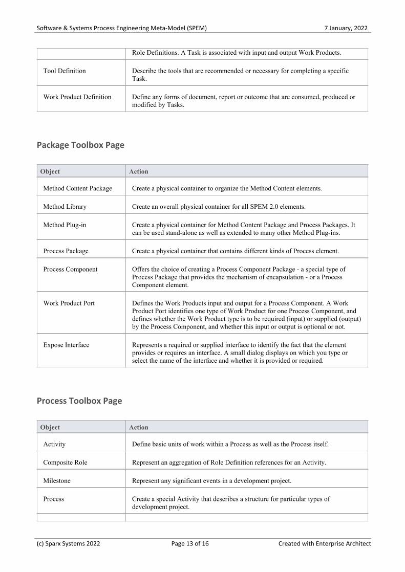
Task Definition Describe an assignable unit of work. Every Task Definition is assigned to specific
(c) Sparx Systems 2022 Page 12 of 16 Created with Enterprise Architect
Software & Systems Process Engineering Meta-Model (SPEM) 7 January, 2022
Role Definitions. A Task is associated with input and output Work Products.
Tool Definition Describe the tools that are recommended or necessary for completing a specificTask.
Work Product Definition Define any forms of document, report or outcome that are consumed, produced ormodified by Tasks.
Package Toolbox Page
Object Action
Method Content Package Create a physical container to organize the Method Content elements.
Method Library Create an overall physical container for all SPEM 2.0 elements.
Method Plug-in Create a physical container for Method Content Package and Process Packages. Itcan be used stand-alone as well as extended to many other Method Plug-ins.
Process Package Create a physical container that contains different kinds of Process element.
Process Component Offers the choice of creating a Process Component Package - a special type ofProcess Package that provides the mechanism of encapsulation - or a ProcessComponent element.
Work Product Port Defines the Work Products input and output for a Process Component. A WorkProduct Port identifies one type of Work Product for one Process Component, anddefines whether the Work Product type is to be required (input) or supplied (output)by the Process Component, and whether this input or output is optional or not.
Expose Interface Represents a required or supplied interface to identify the fact that the elementprovides or requires an interface. A small dialog displays on which you type orselect the name of the interface and whether it is provided or required.
Process Toolbox Page
Object Action
Activity Define basic units of work within a Process as well as the Process itself.
Composite Role Represent an aggregation of Role Definition references for an Activity.
Milestone Represent any significant events in a development project.
Process Create a special Activity that describes a structure for particular types ofdevelopment project.
(c) Sparx Systems 2022 Page 13 of 16 Created with Enterprise Architect
Software & Systems Process Engineering Meta-Model (SPEM) 7 January, 2022
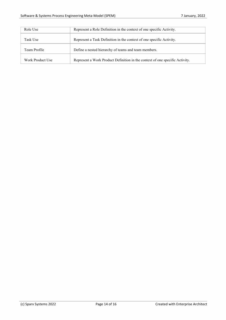
Role Use Represent a Role Definition in the context of one specific Activity.
Task Use Represent a Task Definition in the context of one specific Activity.
Team Profile Define a nested hierarchy of teams and team members.
Work Product Use Represent a Work Product Definition in the context of one specific Activity.
(c) Sparx Systems 2022 Page 14 of 16 Created with Enterprise Architect

Software & Systems Process Engineering Meta-Model (SPEM) 7 January, 2022
More Information
(c) Sparx Systems 2022 Page 15 of 16 Created with Enterprise Architect

Software & Systems Process Engineering Meta-Model (SPEM) 7 January, 2022
(c) Sparx Systems 2022 Page 16 of 16 Created with Enterprise Architect


![Metamodel-based Analysis of Domain-specific …eprints.cs.univie.ac.at/5656/1/[Bork18] Metamodel-based...Metamodel-based Analysis of Domain-speci c Conceptual Modeling Methods Dominik](https://img.pdfslide.net/doc/110x75/5ed7914d67b53e06555d25f2/metamodel-based-analysis-of-domain-specific-bork18-metamodel-based-metamodel-based.jpg)