Embed Size (px)
Citation preview

Software Integration Plan for Dynamic Co-Simulation and Advanced Process Control
Work Performed Under
Activity Number 0004000.6.600.007.002 ARRA
Prepared by D. Olson (LBNL), S. Zitney (NETL)
Prepared for U.S. Department of Energy
National Energy Technology Laboratory
27 June 2012

Soft. Int. Plan for Dynamic Co-Simulation Rev. 0.3draft, 25 Jan 2012
Page | 1-1
Revision Log
Revision
Date
Revised By:
Description
0.3 27 Jan 2012 D. Olson Draft V3, in CCSI template format
Disclaimer This report was prepared as an account of work sponsored by an agency of the United States Government. Neither the United States Government nor any agency thereof, nor any of their employees, makes any warranty, express or implied, or assumes any legal liability or responsibility for the accuracy, completeness, or usefulness of any information, apparatus, product, or process disclosed, or represents that its use would not infringe privately owned rights. Reference herein to any specific commercial product, process, or service by trade name, trademark, manufacturer, or otherwise does not necessarily constitute or imply its endorsement, recommendation, or favoring by the United States Government or any agency thereof. The views and opinions of authors expressed herein do not necessarily state or reflect those of the United States Government or any agency thereof.

Soft. Int. Plan for Dynamic Co-Simulation Rev. 0.3draft, 25 Jan 2012
Page | 1-2
Table of Contents 1.0 Introduction ...................................................................................................................... 1-1
2.0 Goals ................................................................................................................................ 2-2
3.0 Technical Description ...................................................................................................... 3-3
4.0 Tasks ................................................................................................................................ 4-7
5.0 Summary .......................................................................................................................... 5-9
6.0 Appendix – Use Cases ................................................................................................... 6-10
7.0 Appendix: Commercial tools ......................................................................................... 7-25
List of Figures
Figure 3-1 . Illustration showing the communication paths and technologies between the four main dynamic simulation frameworks. ................................................................................ 3-4
Figure 6-1 Use Case 1a. Sim4Me controlling Dynsim and Aspen ............................................ 6-11
Figure 6-2 Use Case 1b. Sim4Me controlling Dynsim and gPROMS ...................................... 6-12
Figure 6-3 Use Case 1c. Sim4Me controlling Dynsim, Aspen, gPROMS ................................ 6-13
Figure 6-4 Use Case 1d. Sim4Me controlling Dynsim and Matlab/Simulink ........................... 6-14
Figure 6-5 Use Case 1e. Sim4Me controlling Dynsim, gPROMS and Matlab/Simulink ......... 6-15
Figure 6-6 Use Case 2a. Aspen OTS controlling Aspen Dynamics and Dynsim ...................... 6-16
Figure 6-7 Use Case 2b. Aspen OTS controlling Aspen Dynamics and gPROMS ................... 6-17
Figure 6-8 Use Case 2c. Aspen OTS controlling Aspen Dynamics, gPROMS and Dynsim ..... 6-18
Figure 6-9 Use Case 2d. Aspen OTS controlling Aspen Dynamics, gPROMS, Matlab/Simulink and Dynsim ........................................................................................................................ 6-19
Figure 6-10 Use Case 2e. Aspen OTS controlling Aspen Dynamics and Matlab/Simulink ...... 6-20
Figure 6-11 Use Case 3a. Matlab controlling Matlab/Simulink and Dynsim ............................ 6-21
Figure 6-12 Use Case 3b. Matlab controlling Matlab/Simulink, Dynsim and gPROMS .......... 6-22
Figure 6-13 Use Case 3c. Matlab controlling Matlab/Simulink, Dynsim and Aspen Dynamics 6-23
Figure 6-14 Use Case 3d. Matlab controlling Matlab/Simulink, Dynsim, gPROMS and Aspen Dynamics ........................................................................................................................... 6-24

Soft. Int. Plan for Dynamic Co-Simulation Rev. 0.3draft, 25 Jan 2012
Page | 1-3
Figure 7-1 Sim4Me/Dynsim Framework ................................................................................... 7-25

Soft. Int. Plan for Dynamic Co-Simulation Rev. 0.3draft, 25 Jan 2012
Page | 1-1
1.0 Introduction It is assumed that the reader is familiar with the requirements and technical specifications provided in Dynamic_Co_Simulation_CCSI_Spec_v1.doc and NETL_APC_Spec_v4.doc.
A complete description and model for dynamic simulation and control of a coal-fired power plant with carbon capture is a very complex problem. To make the problem more tractable tractable and to achieve real-time performance for training applications, it is broken down into subsystems which can be studied with a high degree of independence. And, given the collaborative nature of the problem (and the CCSI project), the different subsystems of a complete plant are modeled in dynamic simulation frameworks from different software vendors. This plan describes integrating dynamic co-simulations running in the following frameworks:
• Invensys Dynsim/Sim4Me
• AspenTech Aspen Plus Dynamics/ Aspen OTS Framework
• PSEnterprise gPROMS
• Mathworks Matlab/Simulink
A brief description and reference information for each of these frameworks is given in the appendix on Commercial Tools.
The overall system has three modes of operation according to the type of use. For real-time power plant applications, including operator training systems (OTSs), Sim4Me provides the integration and run-time control for the overall dynamic simulation (mode 1). For carbon capture research uses, the dynamic simulations are coordinated by the Aspen OTS Framework executive (mode 2). For advanced process control research uses, the simulations are coordinated by the Mathworks Matlab/Simulink framework (mode 3).
An important question is what task is providing the overall control of the carbon capture research co-simulations when the carbon capture models are implemented in gPROMS. This could be implemented in a high-level gPROMS model that coordinates all the lower level models, or possibly using Sim4Me or Matlab as the control environment. This question is largely unresolved in this document at this point in time. This may lead to a 4th mode of operation use cases.

Soft. Int. Plan for Dynamic Co-Simulation Rev. 0.3draft, 25 Jan 2012
Page | 2-2
2.0 Goals 1. Integration for the purposes of CCSI Element 4 Dynamic Simulation and Control activities
2. Provide package of integrated power plant and carbon capture dynamic simulations and operator training system for industrial partners.
This document describes the integration plan to achieve Goal 1. Goal 2 is to be considered at a later date.

Soft. Int. Plan for Dynamic Co-Simulation Rev. 0.3draft, 25 Jan 2012
Page | 3-3
3.0 Technical Description The primary purpose of this work is to coordinate and synchronize process simulations where parts of the model are implemented in different commercial tools. The OPC specifications and tools (described in more detail below) are well suited to form the basis of the necessary communications framework. Three of the four commercial modeling frameworks already support OPC interfaces but the gPROMS modeling framework does not natively support OPC, so one important aspect of the integration is about coupling gPROMS to the OPC infrastructure. Beyond the basic communications and synchronization infrastructure there will be a collection of issues about system initialization, data and configuration management, and possibly a unified user interface. Given these aspects of the problem, the work can be categorized into the following areas:
• communications infrastructure – supporting starting, stopping, saving and reloading initial conditions, and time & data synchronization between running models
• gPROMS integration – mechanism to interface gPROMS models with the system
• configuration management – supports initialization, version control, data management
• user interface – any new user interface development required, probably minimal for goal 1 but significant effort for goal 2.
COMMUNICATIONS INFRASTRUCTURE
Figure 3-1 below illustrates the communication paths and technologies that couple the three dynamic simulation frameworks. The Dynsim OPCEngine is a simulation engine controlled by the Sim4me executive that also acts as an OPC client to arbitrary OPC servers. The Aspen OTS/Aspen Dynamics framework includes an OPC server and the Dynsim OPCEngine will provide the client interface to control the Aspen OTS based simulations. For a particular simulation model one will configure the OPCEngine for the set of OPC tags necessary to share the process variables and time synchronization control parameters so that Dynsim and Aspen Dynamics models make a consistent co-simulation model.
For the use cases where Advanced Process Controls are implemented in Matlab/Simulink one is able to use a direct proprietary interface to execute Aspen Dynamics models directly from Simulink as well as using the Mathworks OPC Toolbox that provides an OPC client interface to arbitrary OPC servers. In order to interface Simulink to Sim4me/Dynsim models one can use the Cogent OPCDatahub tool, that provides client and server OPC interfaces as well as options for data transformations.

Soft. Int. Plan for Dynamic Co-Simulation Rev. 0.3draft, 25 Jan 2012
Page | 3-4
Figure 3-1 . Illustration showing the communication paths and technologies between the four main dynamic simulation frameworks.
OPC
OPC can form the backbone of the inter-process communications necessary for the synchronized dynamic co-simulations using the software frameworks mentioned above. Historically, OPC was an acronym for “OLE for Process Controls” based on Microsoft OLE (object linking and embedding) but the underlying technology has evolved to DCOM and SOAP and OPC now means a set of interoperability standards for industrial automation. The OPC Foundation (www.opcfoundation.org) is a consortium that manages the standards specifications, reference implementations and compliance testing for software conforming to the assortment of OPC standards. OPC defines a client-server architecture with standards that fall into three classes, OPC DA, OPC HAD, OPC A&E. OPC DA defines data access (read/write) specifications for live data. OPC HDA defines historical data access generally used for reading/writing logged OPC DA data. OPC A&E defines alarms and events. These standards use the underlying DCOM specifications from Microsoft. In addition, the latest OPC standards have a new Unified Architecture (UA) which is based on SOAP rather than DCOM but currently, most software vendors products are still using the DCOM-based OPC standards. The UA specifications are

Soft. Int. Plan for Dynamic Co-Simulation Rev. 0.3draft, 25 Jan 2012
Page | 3-5
backward compatible with the DCOM-based specifications so work in CCSI using the DCOM version of interfaces should still be useful when vendors advance to UA interfaces.
In addition to the standards, there is a market for tools and utilities based on OPC and several vendors have tools that can be useful to CCSI for integrating the dynamic process co-simulation tools.
OPC servers publish available data in a hierarchically structured space that OPC clients are able to inspect and then choose which parameters used and propagated via read/write data functions that tie the co-simulation together. In this context, managing the overall co-simulation model becomes an exercise in managing the OPC data space of the various OPC clients & servers as well as transformations of relevant parameters.
OPC runs in a windows environment, processes are easily distributed across multiple hosts. There are some tools for interface to linux environments but that is likely not necessary for CCSI.
GPROMS INTERFACE
gPROMS includes several features for interfacing model calculations with other applications. For co-simulation uses the Foreign Object Interface (FOI) and the Foreign Process Interface (FPI) are the most useful. They provide essentially the same interface to executing a gPROMS model, the difference being that with FOI a gPROMS model is embedded in the same process and with FPI the gPROMS model runs in a separate process.
Three options for interfacing to gPROMS, shown on most of the diagrams are:
• Option A – implement a custom Sim4Me engine using the YGSIM example code from Invensys with either the gPROMS FOI or FPI.
• Option B – implement a custom OPC interface using an OPC development kit and the gPROMS FOI or FPI.
• Option C – use Matlab with the OPC Toolbox and the gO:MATLAB interface to execute gPROMS models. In this case the interface logic is implemented in Matlab.
Of these, Option A has limited value since it is tightly coupled to Sim4Me and won’t work for uses that do not otherwise need Sim4Me. Option B has the most flexibility and functionality but is also probably somewhat more labor intensive than Option A. Option C may be the easiest to implement but needs some testing to determine if all the functionality can be handled via the OPC Toolbox.
Given these considerations, Option C should be the first to consider. To aid in understanding the tradeoffs of Options A & B one should try the various application uses of Dynsim – gPROMS co-simulation using Excel, as both Sim4Me and gPROMS provide an interface to Excel.

Soft. Int. Plan for Dynamic Co-Simulation Rev. 0.3draft, 25 Jan 2012
Page | 3-6
CONFIGURATION MANAGEMENT
Each of the commercial simulation frameworks have their own means of handling model definitions, configurations, initial conditions, presentation of results and preparing the system to be ready to run a simulation. As the co-simulation system is being developed it will work to just continue to use the individual packages features and interfaces for these purposes. In order to make a coherent system with reproducible results there will need to be a means to coordinate these, track all the files, and define versions of the co-simulation models.
The interface of the packages to the OPC communication infrastructure is configured at run time, usually via files, and this configuration also needs to be managed and the configuration steps coordinated with the preparations for model execution.
Most of the development and testing work should be possible on a single system but for actual uses it is likely that the co-simulation is distributed across several computer systems and the configuration management will need to handle this distributed system.
USER INTERFACE
Initial development and testing can be accomplished using whatever user interfaces exist in the commercial tools as well as just OS level utilities for handling files, launching programs, etc. However, in order to use the system in reliable production uses, even for experts (goal 1), there will need to be some user interface that helps guide the workflow for configuration, execution, versioning and archiving to enable reproducible results.
To produce a system that can be used by industrial users (goal 2) the user interface needs to be more complete and able to handle many error conditions. All the features of this user interface will need to be identified and developed as part of a user centered design process with some actual industrial users once the base infrastructure of the system is working.
It may actually be the case that dynamic co-simulation for industrial users should fit into the UQ framework. In this case, the user interface is not necessarily a full featured graphic UI but instead more about packaging the models and a script level wrapper so a comprehensive co-simulation is executed in batch mode behind the CCSI Gateway where the point of the models is to expore behavior under a range of initial conditions.
Soft. Int. Plan for Dynamic Co-Simulation Rev. 0.3draft, 25 Jan 2012
Page | 4-7
4.0 Tasks
The tasks listed below identify the work items to achieve goal 1 ( a system usable by Element4). The tasks are listed in the time order necessary except that some tasks could be carried out in parallel with some others, depending upon available effort.
1. Write plan This document.
2. Set up development environment Hardware ~ 8-core, 16GB mem, windows (XP, 7, 2008, 2008R2?) Software & licenses for Dynsim/Sim4me, Aspen, Matlab/Simulink, OPC Toolbox, OPCDataHub, … OPC UA works on linux as well as Windows so we can consider if running gPROMS on linux is useful in this context.
3. Obtain sample models and instructions from Element4 team Debangsu sent Dynsim & Aspen models & test scenario. Also need gPROMS models.
4. Test Sim4Me-Aspen co-simulation using OPC This test will show if Dynsim and Aspen OTS software systems include sufficient functionality or if additional functionality is required in the OPC interface, perhaps using the OPC DataHub.
5. Test Sim4Me-gPROMS co-simulation with Excel Sim4Me includes an Excel Engine interface to MS Excel and gPROMS also has an interface to Excel via COM. The test is to develop and use an Excel workbook that interfaces to both Sim4Me and gPROMS and see if this Excel “bridge” will work to run a useful co-simulation. The result will provide information useful to the choice of interface for gPROMS is appropriate.
6. Test Sim4Me-gPROMS co-simulation via Matlab OPC Toolbox & gO:MATLAB Run the same application tests as 4 but with gPROMS interfaced via gO:MATLAB and the Matlab OPC Toolbox. Results will indicate what range of functionality is covered by Option C.
7. Test prototype system Option C Configure and run simple application tests including Dynsim, Aspen, Matlab and gPROMS.
8. Element4 prototype testing with Option C Configure and run typical application tests including Dynsim, Aspen, Matlab and gPROMS. Tests should be run join tly or with very close feedback between Elements 4 & 5.
9. Decide on Option A, B, and/or C for initial system If Option C is not sufficient given earlier test results, run additional tests pertaining to Options A and B and make choice of A, B, and/or C. There should be NDA-like
Soft. Int. Plan for Dynamic Co-Simulation Rev. 0.3draft, 25 Jan 2012
Page | 4-8
discussions with Invensys and PSE about any commercial activities that may solve the interface problem. Depending on test results and information available it could be that anywhere from none to all of these options are appropriate to implement. It is necessary to consider the license requirements of any 3rd party interface code used.
10. Implement gPROMS interface (Options A, B, C) Develop the code (if any) and test the gPROMS interface of choice, until working.
11. Decide on and design prototype configuration management system The experiences of previous system testing should provide information that is written up as detailed requirements for the functionality of the configuration management system. Discuss (review) design with Element 4 & 5 teams.
12. Implement prototype configuration management system Implement and test the prototype configuration management system.
13. Element4 testing initial system Element 4 team carries out tests of the full range of functionality for each of the co-simulation usage modes. This should be done in close cooperation and timely interaction with Element 5 so bugs and issues are resolved quickly.
14. Start user centered UI design While Element 4 starts using the system for useful simulations the Element 5 UI person (or team) should begin to look at usage and interact with potential industrial users on needs and features.
Soft. Int. Plan for Dynamic Co-Simulation Rev. 0.3draft, 25 Jan 2012
Page | 5-9
5.0 Summary
The current status is that Task 1 is nearly complete and some work has been done on Tasks 2 & 3. Some testing has been done with a few of the OPC tools but no realistic application testing has been carried out yet, primarily due to not having licenses for necessary products. What we can do is prioritize the next steps for how to proceed with the co-simulation integration.
The first priority and perhaps easiest thing to set up is a Sime4Me/Dynsim – Aspen OTS/Aspen Dynamics co-simulation. This will require the necessary Aspen licenses. LBNL has an evaluation license for Dynsim valid through 8/31/2012 and that will need to be replaced or extended as appropriate. LBNL has the testing setup to run Windows XP machines for this work.
The next target should be to explore the coupling of gPROMS to Sim4Me/Dynsim using the Matlab OPC Toolbox and the gO:MATLAB feature from PSE. This will require the appropriate gPROMS, Dynsim and Matlab licenses and can also be run in the LBNL Windows XP testing environment. It also requires suitable Dynsim and gPROMS models so that the co-simulation has a meaningful degree of functionality.
The next target would be to include the Advanced Process Controls features modeled in Matlab/Simulink combined with either of the first two targets. This requires the additional licenses for Simulink as well as the appropriate models implemented in Simulink.
After achieving the above targets the project should then re-evaluate the plans and define technical targets for additional work. There will be significant knowledge and experience gained in achieving the above targets that it is not useful to predict additional future work at this time.

Soft. Int. Plan for Dynamic Co-Simulation Rev. 0.3draft, 25 Jan 2012
Page | 6-10
6.0 Appendix – Use Cases
The use cases listed below are chosen to illustrate the technical aspects of the software integration necessary to enable the co-simulation uses for optimizing (eventually) full scale coal-fired power plants including the CO2 capture equipment to achieve the operational goals of CCSI. The application use cases would likely be organized and described differently. However, for any particular application use case one should be able to identify which technical use case below would be used for that application. (If there are application cases that do not map on to the list below, please let us know!).
An important characteristic of these co-simulation use cases is that the complete system being modeled is broken down into a collection of sub-models that function independently except for being controlled and synchronized at appropriate time points by the master control process for the simulation. This means that communications for any of the sub-models is only with the master controller (spoke & hub model) and not between sub-models directly (a mesh).
The use cases below are organized according to the framework providing the master controller for the simulations, which we call modes. For mode 1 the Sim4Me framework from Invensys is providing the control, for mode 2 the Aspen OTS framework is providing the control and for mode 3 the Matlab framework is providing the control.
For each use case below a brief description of the options or plan for the software integration is given.

Soft. Int. Plan for Dynamic Co-Simulation Rev. 0.3draft, 25 Jan 2012
Page | 6-11
MODE 1: SIM4ME IS MASTER
Case 1a: Sim4Me co-simulation with Dynsim and Aspen Dynamics
Communication via OPC using Dynsim OPCEngine to Aspen OTS framework which is OPC enabled. This is illustrated in the figure below. It may possibly need additional OPC tools from MatrikonOPC or Cogent to achieve the full functionality for co-cimulation but this needs testing when both Dynsim and Aspen licenses are available.
Figure 6-1 Use Case 1a. Sim4Me controlling Dynsim and Aspen

Soft. Int. Plan for Dynamic Co-Simulation Rev. 0.3draft, 25 Jan 2012
Page | 6-12
Case 1b: Sim4Me co-simulation with Dynsim and gPROMS
Can be tested using Sim4Me Excel engine, gO:RUN Excel and MS Excel. The Excel link may not be reliable or automated enough for production use. Production likely requires a custom link to gPROMS. This link could be implemented via custom Sim4Me engine based on YGSIM (option A), or as a custom OPC server for gO:RUN (option B). An OPC server would communicate with Sim4Me via the Dynsim OPCEngine. Another alternative (option C) is to execute the gPROMS model via Matlab using OPC to the Matlab OPC Toolbox and the gO:MATLAB interface from PSE. In the latter option, Matlab is simply serving as a connectivity option for executing the gPROMS model and does not include any process models itself. These options with their associated communications paths are shown below.
Figure 6-2 Use Case 1b. Sim4Me controlling Dynsim and gPROMS
Soft. Int. Plan for Dynamic Co-Simulation Rev. 0.3draft, 25 Jan 2012
Page | 6-13
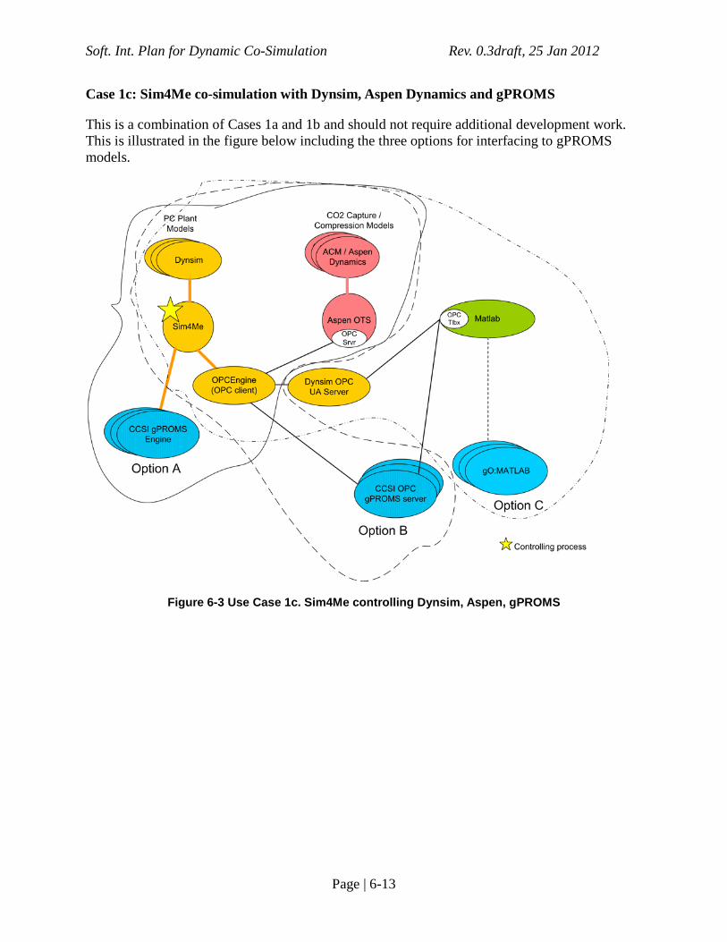
Case 1c: Sim4Me co-simulation with Dynsim, Aspen Dynamics and gPROMS
This is a combination of Cases 1a and 1b and should not require additional development work. This is illustrated in the figure below including the three options for interfacing to gPROMS models.
Figure 6-3 Use Case 1c. Sim4Me controlling Dynsim, Aspen, gPROMS

Soft. Int. Plan for Dynamic Co-Simulation Rev. 0.3draft, 25 Jan 2012
Page | 6-14
Case 1d: Sim4Me co-simulation with Dynsim and Matlab
One possibility is to use the Matlab OPC Toolbox to communicating with Sim4Me via OPC as illustrated below. The OPC DataHub can be used as the OPC server connecting the two OPC clients but it may work to uses the Dynsim OPC UA Server instead of the OPC DataHub. An alternative is to make a custom Sim4Me engine (based on YGSIM) which calls the Matlab model as an embedded application, however, this would require considerably more development work and is not shown below.
Figure 6-4 Use Case 1d. Sim4Me controlling Dynsim and Matlab/Simulink
Soft. Int. Plan for Dynamic Co-Simulation Rev. 0.3draft, 25 Jan 2012
Page | 6-15
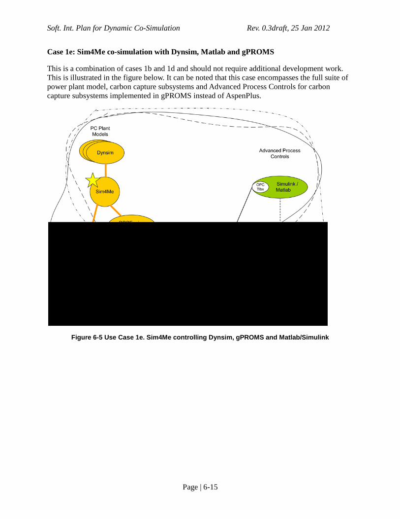
Case 1e: Sim4Me co-simulation with Dynsim, Matlab and gPROMS
This is a combination of cases 1b and 1d and should not require additional development work. This is illustrated in the figure below. It can be noted that this case encompasses the full suite of power plant model, carbon capture subsystems and Advanced Process Controls for carbon capture subsystems implemented in gPROMS instead of AspenPlus.
Figure 6-5 Use Case 1e. Sim4Me controlling Dynsim, gPROMS and Matlab/Simulink
Soft. Int. Plan for Dynamic Co-Simulation Rev. 0.3draft, 25 Jan 2012
Page | 6-16
MODE 2: ASPEN OTS IS MASTER
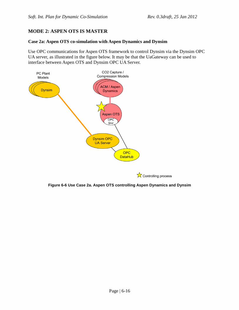
Case 2a: Aspen OTS co-simulation with Aspen Dynamics and Dynsim
Use OPC communications for Aspen OTS framework to control Dynsim via the Dynsim OPC UA server, as illustrated in the figure below. It may be that the UaGateway can be used to interface between Aspen OTS and Dynsim OPC UA Server.
Figure 6-6 Use Case 2a. Aspen OTS controlling Aspen Dynamics and Dynsim
Soft. Int. Plan for Dynamic Co-Simulation Rev. 0.3draft, 25 Jan 2012
Page | 6-17
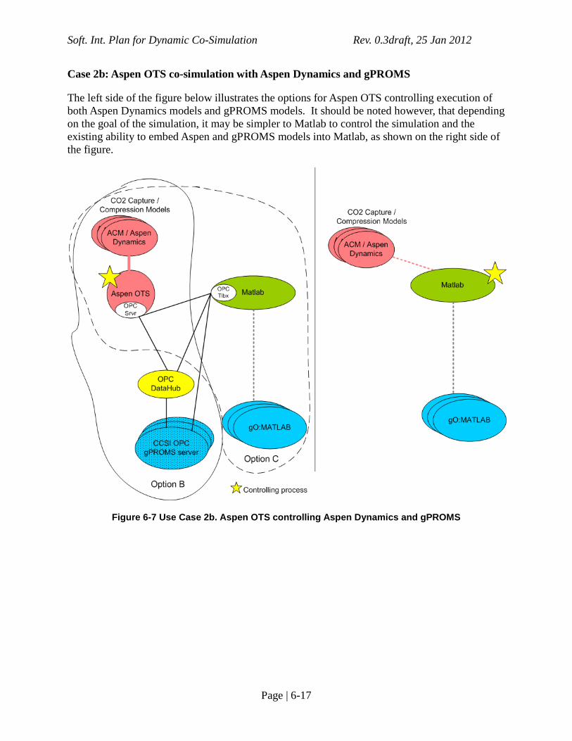
Case 2b: Aspen OTS co-simulation with Aspen Dynamics and gPROMS
The left side of the figure below illustrates the options for Aspen OTS controlling execution of both Aspen Dynamics models and gPROMS models. It should be noted however, that depending on the goal of the simulation, it may be simpler to Matlab to control the simulation and the existing ability to embed Aspen and gPROMS models into Matlab, as shown on the right side of the figure.
Figure 6-7 Use Case 2b. Aspen OTS controlling Aspen Dynamics and gPROMS

Soft. Int. Plan for Dynamic Co-Simulation Rev. 0.3draft, 25 Jan 2012
Page | 6-18
Case 2c: Aspen OTS co-simulation with Aspen Dynamics, Dynsim and gPROMS
It should be that the work for cases 1b and/or 2b satisfy this case, shown in the figure below.
Figure 6-8 Use Case 2c. Aspen OTS controlling Aspen Dynamics, gPROMS and Dynsim

Soft. Int. Plan for Dynamic Co-Simulation Rev. 0.3draft, 25 Jan 2012
Page | 6-19
Case 2d: Aspen OTS co-simulation with Aspen Dynamics, Dynsim, gPROMS and Matlab
In addition to the solution for 2c, the Matlab OPC Toolbox can be used to communicate with the Aspen OTS framework OPC network, as shown below. The difference compared to 2c is that there is now significant logic implemented in the Matlab/Simulink process.
Figure 6-9 Use Case 2d. Aspen OTS controlling Aspen Dynamics, gPROMS, Matlab/Simulink and Dynsim
Soft. Int. Plan for Dynamic Co-Simulation Rev. 0.3draft, 25 Jan 2012
Page | 6-20
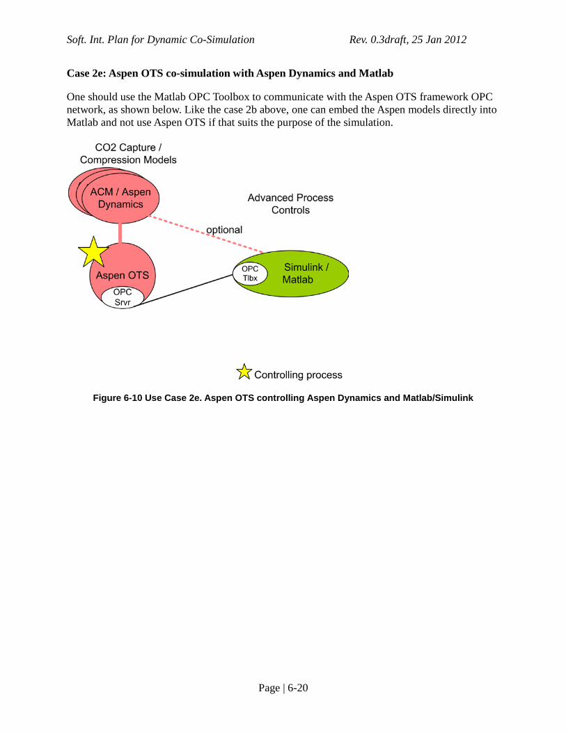
Case 2e: Aspen OTS co-simulation with Aspen Dynamics and Matlab
One should use the Matlab OPC Toolbox to communicate with the Aspen OTS framework OPC network, as shown below. Like the case 2b above, one can embed the Aspen models directly into Matlab and not use Aspen OTS if that suits the purpose of the simulation.
Figure 6-10 Use Case 2e. Aspen OTS controlling Aspen Dynamics and Matlab/Simulink

Soft. Int. Plan for Dynamic Co-Simulation Rev. 0.3draft, 25 Jan 2012
Page | 6-21
MODE 3: MATLAB IS MASTER
Case 3a: Matlab co-simulation with Dynsim
Use Matlab OPC Toolbox to control Dynsim via the Dynsim OPC UA server, as shown below. It may be that the UaGateway is needed in connecting the classic OPC Toolbox features with the OPC UA Server.
Figure 6-11 Use Case 3a. Matlab controlling Matlab/Simulink and Dynsim
Soft. Int. Plan for Dynamic Co-Simulation Rev. 0.3draft, 25 Jan 2012
Page | 6-22
Case 3b: Matlab co-simulation with Dynsim and gPROMS
If a gPROMS OPC server is implemented then gPROMS model can be controlled using the Matlab OPC Toolbox as well as Dynsim. Otherwise one can run gPROMS as an embedded application in Matlab. These options are shown in the figure below.
Figure 6-12 Use Case 3b. Matlab controlling Matlab/Simulink, Dynsim and gPROMS

Soft. Int. Plan for Dynamic Co-Simulation Rev. 0.3draft, 25 Jan 2012
Page | 6-23
Case 3c: Matlab co-simulation with Dynsim and Aspen Dynamics
As shown below, usethe Matlab OPC Toolbox to communication with Dynsim OPC UA server & Dynsim and also with Aspen OTS framework OPC network to control Aspen Dynamics. Alternatively one can use the available Matlab interface for Aspen Dynamics to call Aspen as an embedded model from Matlab in which case the Aspen OTS framework is not used.
Figure 6-13 Use Case 3c. Matlab controlling Matlab/Simulink, Dynsim and Aspen Dynamics

Soft. Int. Plan for Dynamic Co-Simulation Rev. 0.3draft, 25 Jan 2012
Page | 6-24
Case 3d: Matlab co-simulation with Dynsim, Aspen Dynamics and gPROMS
As shown below, usethe Matlab OPC Toolbox to communication with Dynsim OPC UA server. Control Aspen either via OPC or as embedded model in Matlab. Control gPROMS either via OPC or as embedded model in Matlab.
Figure 6-14 Use Case 3d. Matlab controlling Matlab/Simulink, Dynsim, gPROMS and Aspen Dynamics

Soft. Int. Plan for Dynamic Co-Simulation Rev. 0.3draft, 25 Jan 2012
Page | 7-25
7.0 Appendix: Commercial tools
SIMULATION FRAMEWORKS
Invensys Dynsim/Sim4Me
Sim4Me provides the interactive user interface for designing and executing process models in Dynsim, and is part of the SimSci-Esscor suite of products from Invensys (iom.invensys.com). This framework uses CAPE-OPEN for internal communications and control and has many features for control and synchronization of models deployed across several instances of Dynsim (co-simulation), including managing initial conditions (ICs), saving state, rollback to previous conditions (backtrack) and executing scenarios as part of operator training. 3rd party models (called engines) can be executed and controlled directly by Sim4Me using CAPE-OPEN interfaces or also by using the OPC interfaces provided by the OPCEngine. The Dynsim engine models can also be controlled and executed by 3rd party systems using the OPC interfaces provided through the OPC UA Server. Interfacing with classic OPC tools can be achieved using the UaGateway from Unified Automation. An example simulation engine called YGSIM is provided in C++ and can be used as a basis for developing a new custom simulation engine.
These features are illustrated in the figure below.
Figure 7-1 Sim4Me/Dynsim Framework
Aspen OTS
The Aspen OTS framework can provide operator training functionality as well as general purpose execution of dynamic simulations using AspenPlus Dynamics. Aspen OTS can coordinate any number of simultaneous AspenPlus Dynamics models running and has features to partition one mode across several AspenPlus Dynamics instances in order to achieve greater

Soft. Int. Plan for Dynamic Co-Simulation Rev. 0.3draft, 25 Jan 2012
Page | 7-26
performance. Aspen OTS integrates into a larger scale simulation system via OPC and includes an OPC Server.
Aspen Dynamics process simulations can be used as a block in a Simulink flowsheet.
gPROMS
The gPROMS simulation framework from PSE (Process Systems Enterprise, www.psenterprise.com) consists of numerous components for process modeling, simulation and optimization. The key components for the work here are:
• ModelBuilder – the interactive user interface for designing process models and running simulation and optimizations of those models. Models developed in ModelBuilder can be exported to run in several other contexts described below.
• gO:RUN – an environment for executing models as a standalone process or as an embedded function or process in another application. The Foreign Object Interface (FOI) enables executing models as embedded functions. The Foreign Process Interface (FPI) allows control and execution of models synchronously or asynchronously with another application.
• gO:MATLAB – allows executing models as functions in Matlab.
• gO:Simulink – allows embedding a model in a Simulink flowsheet, or allows embedding a Simulink flowsheet model in a gPROMS model.
gPROMS does not support OPC interfaces directly although there is 3rd party software from IPCOS (www.ipcos.com) that provides an interfaces supporting OPC DA 1.05 and 2.0. Information from a PSE representative on OPC use is that the two customers using OPC heavily have implemented their own OPC interface for gPROMS rather than using the IPCOS software.
Matlab/Simulink
Matlab is the popular numerical modeling and data analysis environment with a large range of additional tools specific to various application areas, interfaces to many 3rd party simulation tools and API for custom applications. The Simulink add-on to Matlab provides capability to design process flowsheets, ability to interface to many process modeling tools. Interfaces are available to execute gPROMS and Aspen models from Matlab. The OPC Toolbox for Matlab enables an OPC client interface to OPC based process control systems.
USEFUL TOOLS
OPC DataHub
The OPCDataHub product from Cogent (www.cogentdatahub.com) provides a general purpose bridging and gateway tool for OPC communications, supporting simultaneously any number of both client and server interfaces. One can configure OPCDataHub to provide a range of translation and transformations on data elements in other OPC clients and servers. It also

Soft. Int. Plan for Dynamic Co-Simulation Rev. 0.3draft, 25 Jan 2012
Page | 7-27
supports connections to Excel for additional algorithm and UI functionality. One of the uses applicable here is as a bridge between the OPC Client interfaces of the Dynsim/Sim4me and Matlab/Simulink environments, as described below.
UaExpert
The UaExpert tool from Unified Automation (www.unified-automation.com) is an OPC UA compliant client recommended by Invensys for configuring theDynsim OPC UA Server.
UaGateway
The UaGateway tool from Unified Automation (www.unified-automation.com) is a wrapper/proxy tool for interfacing classic OPC DA products with OPC UA products.