Embed Size (px)
Citation preview

f]~j I~ORTLAND CEMENT ASSOCIATION
SOIL-CEMENT
INSPECTOR’S
MANUAL
PAO5O.O 3

SOIL-CEMENT
INSPECTOR’S
MAN UAL
PORTLAND CEMENT ASSOCIATION
5420 Old Orchard Road, Skokie, Illinois 60077-1083Phone: 847.966.6200; Fax: 847.966-9781Web site: www.portcement.org
© 2001 Portland Cement AssociationAll rights reserved

Contents Foreword
Foreword. 3
An introduction to Soil-Cement 4
Chapter 1 Checklist 6
Chapter 2 Inspection of Site Preparation 8
Identification of Soil Materials 8Site Preparation 8Equipment Check 11Pulverization 13
Chapter 3 Inspection of Processing Operations 15
Cement Application 15Water Application 31Uniformity of Mix: Depth and Width of Treatment . . . 44Compaction 46Finishing 47Joint Construction 48Degree of Compaction and Final Depth Check 49Curing 57Opening to Traffic 57Maintenance 57
Appendix 59
This second edition of Soil-Cement Inspector’s Manual outlines and illustrates procedures for inspection of soil-cementconstruction. Each step of proper inspection and control isexplained; sample problems are given to show how to compute material quantities and perform field tests. Tables andcharts to simplify these calculations are also included.
Other PCA publications of interest to the soil-cement inspector are listed at the back of this manual.
Equipment for Field Tests 59Form Sheets 60

An Introductionto Soil-Cement
Soil-cement is a mixture of pulverized soil material and measured amounts of portland cement and water, compacted tohigh density. As the cement hydrates, the mixture becomes ahard, durable paving material. A bituminous wearing courseis placed on the soil-cement base to complete the pavement.
Only three basic ingredients are needed for soil-cement:soil material, portland cement, and water. The soil in soil-cement can be a wide variety of materials. Either in-place orborrow material can be used. Old granular-base roads, withor without their bituminous surfaces, can be recycled to makesoil-cement.
Soil-cement is sometimes called cement-treated base orcement-stabilized-aggregate base. Regardless of what it iscalled, the principles governing its composition and construction are the same.
Before construction with soil-cement starts, the soil materials that will be treated with cement should have been identified and representative samples of each type tested. Thesetests determine the minimum cement content required toharden each material adequately and the approximate optimum moisture content and density values for use in construction.
Soil-cement road construction involves two steps—preparation and processing. Variations in these steps are dictatedby the type of mixing equipment used. Regardless of theequipment and methods used, it is essential to have an adequately compacted, thorough mixture of soil material with theproper amounts of cement and moisture. The completed soil-cement must be adequately cured.
Soil, cement, and water can be (1) mixed in place using traveling mixing machines, or (2) mixed in a central mixing plant.The types of mixing equipment are
1. Traveling mixing machinesa. Flat-transverse-shaft type
Single-shaft mixerMultiple-shaft mixer
b. Windrow-type pugmill
2. Central mixing plantsa. Continuous-flow-type pugmillb. Batch-type pugmillc. Rotary-drum mixers
Steps for construction with traveling mixing machines are1. Preparation
a. With in-place soil materialShape roadway to crown and grade.Scarify roadway soil material.Pulverize if necessary.Prewet as needed.Shape prepared soil material.
b. With borrow materialShape subgrade to crown and grade.Compact subgrade.Place borrow material.Shape borrow material.
2. Soil-cement processingSpread portland cement and mix.Apply water and mix.Compact.Finish.Cure.
Construction steps for central-mixing-plant constructionare
1. PreparationShape subgrade to crown and grade.Compact subgrade.
2. Soil-cement processingMix soil material, cement, and water in plant.Haul mixed soil-cement to roadway and spread.Compact.Finish.Cure.
Compacted and finished soil-cement contains sufficientmoisture for adequate cement hydration. A moisture-retainingcover is placed over the soil-cement soon after completion toretain this moisture and permit the cement to hydrate. Mostsoil-cement is cured with bituminous material, but other materials (see page 57) are satisfactory.
4 5

Chapter 1 12. Have any defects been repaired for full depth of
Ch treatment?ec IS The proper methods of controlling each of these 12 items aredescribed in following chapters.
Field inspection of soil-cement construction involves the control of five factors:
Cement contentMoisture contentMixingCompactionCuring
The inspector can easily control these factors by organizing the inspection steps into a routine that fits in with the sequence of construction operations.
The following checklist covers the inspection steps requiredto assure quality soil-cement:
1. Have soil surveys, laboratory reports, plans, and specifications been reviewed and correlated with job conditions?
2. Have all soft subgrade areas been corrected? Has theroadway been shaped to crown and grade? Have manhole covers and other obstacles been removed or lowered?
3. Is all of the construction equipment properly adjusted andin good working condition?
4. Have the soil materials been pulverized sufficiently, andwill their moisture contents allow them to mix readily withcement?
5. Has the proper quantity of cement been spread uniformly? Has the central mixing plant been properly calibrated?
6. Is the soil-cement mixture between optimum moistureand 2% above optimum moisture?
7. Is the mixture uniform and thoroughly mixed? Are thewidth and depth of treatment according to the plans?
8. Is the finished surface moist, dense, and free of compaction planes?
9. Is the soil-cement mixture at the transverse constructionjoint well mixed and compacted?
10. Are the specified density and depth of treatment beingachieved?
11. Is sufficient curing material for complete coverage beingapplied? Where subjected to traffic, has the bituminousmaterial been sanded sufficiently to prevent pickup?
8

Chapter 2
Cow
Ix
IzICC
ICCC.)
0Coz0CoI-CowIIC.0
DCo
C
Inspection of Site Preparation
Before processing begins, laboratory reports, soil surveys,plans, and specifications are reviewed by the inspector. Theinspector should be thoroughly familiar with the specificationsand must insist upon compliance with them. The constructionsite is inspected to make sure that the soil materials are atproper grade and adequately pulverized, and that the sub-grade is stable throughout the project.
Identification of Soil MaterialsCement requirements are determined in the laboratory beforeconstruction and are tabulated in the laboratory reports alongwith identification information for the soil. (See Fig. 1.)
The soil materials to be processed in the field are comparedwith the identification data given in the laboratory report andwith information given in the plans and specifications. This willassure the use of the proper amount of cement. If there is anobvious difference between the materials tested and the soilmaterials on the site, further testing may be necessary.
Site PreparationAreas of unstable subgrade must be corrected before processing starts, since proper compaction of soil-cement will notbe possible if the subgrade cannot support the compactionequipment.
Unstable subgrade soils, which usually contain excessmoisture, can generally be detected by observing their stability under the wheels of the motor grader as it shapes the areaprior to soil-cement processing. Shallow wet spots can be improved by aerating and drying. When deep unstable areas areencountered, it is usually necessary to remove the underlyingsoil and replace it with better material. An alternate method ofcorrection is to treat the subgrade with cement.
When in-place soil materials are used, the grade at the startof construction will influence the final cross section. Therefore, before processing is started, the roadway should beshaped to approximate crown and grade. Maintenance of
U
~ I
jj~h
~ ~~ 11111111 ~ll
-~ill~ll r~ ~ -
~ ~ ii ~~ C
Fig. 1. Summary of soil and soil-cement tests on Soil No. C.
8 9

essed. This permits processing over manholes without difficulty or delay. Manhole locations should be accurately referenced with offset stakes. After final finishing but before thesoil-cement has hardened, manhole frames and covers arereplaced. Soil-cement is then tamped (to maximum density)around the structures, or ready mixed concrete is placed andfinished to grade.
Equipment CheckAll equipment necessary for construction must be at the job-site and in good operating condition before processing begins.A short trial run is valuable in assuring proper operation andadjustment of equipment.
Listed below are items that should be checked prior to processing.
Central Mixing
Fig. 2. Unstable subgrade areas can usually be detected byobserving their stability under the motor-grader wheels. Softareas must be corrected before processing starts.
crown and grade prior to soil-cement construction will permitrapid runoff of water during heavy rains and is good insuranceagainst wet spots developing.
Prewetting of dry, in-place soil materials is common practice. Applying water during preparation saves time duringactual processing operations because most of the requiredwater will already have been added to the soil material. In verygranular materials, prewetting prevents cement from sifting tothe bottom of the mix by causing it to adhere more readily tothe sand and gravel particles.
Guide stakes should be set 1 ft (0.3 m) beyond the proposedpavement edges to control the width of treatment and to guidethe equipment operators during construction.
Soil-cement street processing is facilitated by removingmanhole covers and frames and covering the holes withheavy sheet metal or planks just below the depth to be proc
1. Cement feed, Is the cement meter on the central plant ingood condition and in an exposed location where it canconveniently be calibrated? Does the plant include a surgetank between the cement silo and the feeder to maintain aconstant head of cement for the feeder? Have air jets beeninstalled in the hoppers to produce a loose, uniform, accurate flow of cement? Is there a positive connection betweenthe soil feed and cement feed apparatus so that if the cement feed stops, the soil supply will stop?
2. MIxer. Are the paddles all in place and in good condition?Does the spraybar give a uniform, constant spray of water?Can the required quantity of water be delivered through theplant under maximum production?
3. Transporting equIpment. Is the equipment of sufficientcapacity to meet the production requirements? Are protective covers provided for use during bad weather?
4. Spreader. Is it in good operating condition and adjusted tospread the mixed soil-r.ement to the proper loose depth andwidth?
Mixed in Place
1. Cement spreader. Is the conveyor belt or chain on thecement spreader in good condition? Does the spreader run
10 11

smoothly? Are the proper gears and plates installed? Is thetruck hitch operating properly?
2. Cement trucks. Are the cement trucks equipped with special hitches for attaching the cement spreader? Are thetruck beds tight enough to prevent loss of cement? Are thetrucks equipped with tarpaulins for protection against rain?
3. Mixing machines. Are the tines or paddles all in place andin good condition? Does the spraybar on each mixer give auniform, constant spray? Be sure that it does not leak waterwhen turned off.
Water Source and EquipmentIs there any chance that the water source is contaminated?If so, has the water been tested in the laboratory? Is the waterpump in good working order? Are all of the nozzles on thespraybars unclogged? Have all leaks been eliminated?
Motor GraderIs the motor grader blade in good condition and not worn ex- Fig. 4. Screening soil-cement mixture through No. 4 (4.75-mm)cessively? sieve to determine percent pulverization.
Compaction EquipmentFig. 3. Checking for water truck spraybar leakage. Is the tamping roller filled with water or sand? Are the tamping
feet the proper size, shape, and length for the type and thickness of soil to be processed? Are the rubber-tire and steel-wheel rollers of the proper weight?
PulverizationMost soil materials require little if any pulverization beforeprocessing starts. However, the heavier clayey soils do require some preliminary work. The keys to pulverization ofclayey soils are proper moisture control and proper equipment.
Most specifications require that, at the completion of moistmixing, 80% of the soil-cement mixture pass the No. 4 (4.75-mm) sieve and 100% pass the 1-in. (25-mm) sieve, exclusiveof gravel or stone retained on these sieves. This is checkedby making a pulverization test. The test consists of screeninga representative sample of soil-cement through a No. 4(4.75-mm) sieve. Any gravel or stone retained on the sieve is picked
13

Chapter 3out and discarded. The clay lumps retained and the pulverizedsoil passing the No.4(4.75-mm) sieve are weighed separatelyand their dry weights determined. The degree of pulverizationis calculated as follows:
dry weight of soil-cement mixturepassing No. 4 (4.75-mm) sieve
% pulverization . . 100dry weight of total sample exclusiveof gravel retained on No.4(4.75-mm)
sieve
For practical purposes, wet weights of materials are oftenused instead of the corrected dry weights. The wet-weightmeasurements are reasonably accurate and permit immediate adjustments in pulverization and mixing procedures ifnecessary.
Pulverization can be improved by1. Slower forward speed of the mixing machine2. Additional passes, if using a multiple-pass mixing
machine3. Replacing worn mixer teeth4. Prewetting and premixing the soil before processing
beginsSoil material that contains excessive moisture will not mix
readily with cement; therefore, the moisture content of thematerial should be checked visually before cement is applied.The percentage of moisture in the material at the time of cement application should not exceed the optimum moisturecontent.
Inspection of Processing OperationsSoil-cement construction operations are well suited to anorderly procedure of inspection and field control. This procedure is aimed at controlling the amount of cement andwater, and the degree of mixing and compaction.
Daily processing is best carried out in several sections rather than one long section. This permits more efficient use ofequipment and thus speeds up operations. It also permitscompliance with time limits for moist-mixing, compacting, andfinishing, as given in the specifications.
Cement ApplicationSince cement hydration practically ceases when temperatures approach freezing, cement should not be applied whenair temperature is 40°F (4° C) or lower. Cement must not beapplied when the soil material or subgrade is frozen.
The amount of cement required is specified either as a percentage of cement by weight of oven-dry soil material, or inpounds of cement per cubic foot (kilograms per cubic meter)of compacted soil~cement.* Fig. 5can be used to convert fromone to the other if the maximum dry density of the compactedsoil-cement is known.EXAMPLE 1.Calculate the quantity of cement per cubic foot of compactedsoil-cement.GIVEN: Maximum dry density of compacted soil-cement
121.2 lb per cubic foot (1941 kg/m3)Specified cement content by dry weight of soil material... 6%
PROCEDURE: Calculate the weight of soil material by dividingthe weight of soil-cement by the quantity 1 plus the cementcontent expressed as a decimal:
(1.0±0.06) = 114.3 lb per cubic foot (1831 kg/m3)
The quantity of cement in each cubic foot is
121.2 - 114.3 = 6.9 lb per cubic foot (110 kg/m3)
*Previous editions of this handbook used percentage of cement byvolume as an alternate method of expressing cement content Thiswas based on a 94-lb (43-kg) U.S. bag of cement.
15

TABLE 1. Normal Range of Cement Requirements for B- and C-Horizon Soils*
Cement, Cement,Cement pounds per kilograms per
percentage cubic foot of cubic meter ofAASHTO by weight of compacted compacted
Soil Group soil soil-cement soil-cement
A-i-a 3-5 5-7 80-110A-i-b 5-8 7-8 110-130A-2-4
~ 5-9 7-9 110-140
A-2-7 ~A-3 7-il 8-11 130-180A-4 7-12 8-il 130-180A-S 8-13 8-11 130-180A-6 9-15 9-13 140-210A-7 10-16 9-13 140-210
IS
A-horizon soils (topsol s may Contain organic or other material detrimental to cement reaction and thus require highercement factorsFor dark grey to grey A-horizon soils, increase the above Cementcontents 4 percentage po nts 4 b Cu ft 60 kg m j of compactedsoii-cement(; for black A-hor zon soi a 6 percentage points 6 b Cuft [100 kg m I of compacted s cement
TABLE 2. Average Cement Requirementsof Miscellaneous Materials
15- —240
i7 —230
1600- —iOO is 14- 220
15 210
14 200
—los i3 iz 190i700-
i2180
—iio 170
iO i60iSoo- —
• -iso~—25 gV 8
1900- s S
~8- -1306
V -20~
2000- —125 ~ ~ ~6 ___•~
2100- 30 -s — -ioo
—35 -90
2200- V
-140 5— -80
2300--i45
Fig. 5. Cement factor conversion chart.
Cement Application forMixed-in-Place ConstructionBulk Cement spreaders should be operated at a constant slowrate of speed and a relatively constant level of cement kept inthe hopper to obtain a uniform cement spread. A true line atthe edge of the pavement should be maintained by using astringline. There should be no skips between spreading lanes.
Fig. 6 and Table 3 can be used to determine quantities of
Cement, Cement,Cement, pounds per kilograms per
percentage cubic foot of cubic meter ofby weight of compacted compacted
Material soil soil-cement soil-cement
Caliche 7 8 130Chat 7 8 130Chert 8 8 130Cinders 8 8 130Limestone screenings 5 7 110Marl 11 10 160Red dog 8 8 130Scoria containing plus
No 4 material 11 ii 180Scoria (minus No 4
material only) 7 8 130Shale or disintegrated
shale 10 10 160Shell soils 7 8 130Slag (air-cooledl 7 8 130Slag (water-cooled) 12 9 140
16
17

Fig. 6. Quantity of cement per unit length for given depth andwidth of treatment for specified cement contents.
cement per square yard (square meter) of pavement or perlinear foot (meter). If the soil-cement is mixed in windrows, Fig.7 can be used to determine cement quantities per linear foot(meter) of windrow.
Check on Cement SpreadA check on the accuracy of the cement spread is necessaryto ensure that the proper quantity is actually being applied.When bulk cement is being used, the check is made in twoways:
1. Spot check. Place a canvas, usually 1 sq yd (1 m2)in area,
TABLE 3. Cement Spread Requirement, Poundsper Square Yard per Inch of CompactedThickness (kg/rn2 per 10 mm)
cement spread, Cement spread,Cement content. pounds per square Cement content. kilograms per square
pounds per yard per inch of kilograms per meter per 10mmcubic foot of thickness of cubic meter of of thickness ofcompacted compacted compacted compactedsoil-cement soil-cement soil-cement soil-cement
4.5 3.38 72 0.725.0 3.75 80 0.805.5 4.13 88 0.886.0 4.50 96 0.966.5 4.88 104 1.047.0 5.25 112 1.127.5 5.63 120 1 2080 6.0 128 1288.5 6.38 136 1.369.0 6.75 144 1.449.5 7.13 152 1.52
10.0 7.50 160 1.60105 7.88 168 16811.0 8.25 176 1 7611.5 8.63 184 18412.0 9.0 192 1 9212.5 9.38 200 2.0013.0 9.75 208 2.0813.5 10.13 216 2.1614.0 10.50 224 2.2414.5 1088 232 2.3215.0 11 25 240 2.4015.5 1163 248 248160 12.0 256 256
on the roadway ahead of the cement spreader. After thespreader has passed, carefully pick up the canvas andweigh the cement collected on it.
2. Overall check. Check the distance of area over which atruckload of cement of known weight is spread.
EXAMPLE 2.
Determine the linear distance a truckload of cement shouldtravel to spread the required amount of cement.
GIVEN: Required cement content 6.9 lb per cubic foot(110kg m)
Depth of compacted soil-cement 6 in. (150 mm)Width of spread 8 ft (2.4 m)Weight of truckload of cement 15,400 lb (6990 kg)
34 120 us im
5.~I,Iy of cqll~OM 2[ 101,1 logIn no, gb.,, bOoth 0,10 .10111
18 19

Fig. 7. Quantity of cement per unit length of windrow for specifiedcement content.
Fig. 8. weighing cement collected on a square yard (m2) ofcanvas is a check on the quantity of cement spread.
vertically to the bottom edge and read the quantity of cementper unit length required: 27.6 lb per foot (41.1 kg/rn).
The required distance of travel for the 15,400-lb (6990-kg)truckload of cement to obtain the specified cement spreadequals the total weight of cement on the truck divided by thepounds (kilograms) per linear foot (meter) required:
15A00 = 558ft(170m)
If the truck traveled only 530ft (1 61 m), morethan the requiredquantity of cement was applied and the spreader should beadjusted to spread slightly less cement. The quantity of cement actually spread in this case is:
15,400 lb ÷ 530 ft = 29.1 lb/foot (43.3 kg/rn)or
291 lb ft ÷4 cu ft ft* —73 lb per cubic foot (117 kg m
PROCEDURE: Enter Fig. 6 on the top edge at 6.9 lb of cementper cubic foot (110 kg/rn3) and proceed vertically to the 6-in.(150-mm) depth line; proceed horizontally to intersection withline representing 8-ft (2.4-rn) width of spread; then proceed
This is compared to 6.9 lb percubic foot (110kg m ) required.
*Spread is for 1-ft (03-rn) length 8-ft (24-rn) width, and 6-in (150-mm) depth: 1 x 8 x 6 12 4 cu ft ft (037 m m
0
0
:::~
4 ~:~jj~::
8
E
a
0
2
IouaIou IfS Lip _uaAo JO LJ&IaM Lq ~uawa, lu;ond
20 21

Bagged-Cement Spread forMixed-in-Place ConstructionWhen bags of cement are used on small jobs, a simple butexact method for properly placing the bags is necessary. Thebags should be spaced at approximately equal transverse andlongitudinal intervals that will ensure the proper percentageof cement. Positions can be spotted by flags or markers fastened to chains at proper intervals to mark the transverse andlongitudinal rows.
Calibrating Central Mixing PlantsWhen borrow materials are specified, central plants with pug-mill-type mixers or rotary-drum mixers are often used to mixsoil-cement. Use of such equipment makes it necessary toproportion the cement and the soil aggregate before theyenter the mixing chamber. Central mixing plants can be calibrated as explained below.
Continuous-Flow Mixing Plant
Fig. 9. The distance over which a truckload of cement of knownweight spreads is a check on the quantity of cement spread.
Bulk cement that is spread mechanically on the top of awndrow of soil may be checked by forming a trough in the topof the windrow and placing a piece of canvas in the trough.Cement spread is checked by pushing two metal plates intothe top of the windrow exactly 1 ft or 1 m apart. All cement between the plates is carefully collected and weighed. This is adirect method of finding the quantity of cement spread per unitlength.
Generally, the spreader is first adjusted at the start of construction by checking the cement spread per unit length ofwindrow or per square yard (m2). Then, when the proper adjustments have been made, a continuous check of the spreadis easily made by determining the distance over which eachtruckload is spread. Bag cement is checked by counting thenumber of bags placed per 100-ft (30-m) station. It is important to keep a continuous check on cement-spreading operations.
The soil material alone is run through the plant for a givenperiod of time and collected in a truck. This should be done forspecific periods of time, such as 1, 2, and 3 minutes, to determine the uniformity of flow and the quantity of soil material going through the plant. The amount of moist soil per hourdividedby the quantity 1 plus the moisture content (expressed as adecimal) will give the quantity of dry soil per hour.
EXAMPLE 3.
Find the hourly delivery rate of dry soil material.GIVEN: Moist soil material going through the plant per hour
500 tons (454 f)*Moisture content of material 5.5%
PROCEDURE: Delivery rate of dry soil material is
(1.0 ±0055) = 474 tons per hour (430 t/h)
Cement is calibrated in a similar manner by diverting it di-
*1 t = 1 tonne = 1000 kg = 1 Mg
I.I
22 23

a
Cit
Fig. 10. Soil material is collected in a truck to determine rate offeed.
Fig. 12. Collecting soil material from main feeder belt todetermine dry weight and rate of feed.
EXAMPLE 4.
-‘/
I
Fig. 11. Rate of cement feed is calibrated to revolutions of the cement feeder.
rectly from the cement feeder into a truck or suitable containerwhile soil material is going through the plant. A diversion chutedirects the cement from the cement meter to the container.The plant is run at full capacity during calibration so that operations will be comparable to those of actual running conditionsand power drawdown will not affect calibration results duringcement trials. Generally, periods of 15, 30, and sometimes 45seconds are used to determine the uniformity of feed and thequantity of cement delivered.
Determine the amount of cement required per minute.
GIVEN: Specified cement content by weight of dry soil material 6%
PROCEDURE: 474 tons per hour (430 t/h) (from Example 3)of dry soil material requires 474 x 0.06 = 28.4 tons of cementper hour (25.8 t/h), or
28.4x 200060 = 948 lb of cementperminute (430kg mm)
Rather than arbitrarily adjusting the cement feeder until thecorrect amount of cement is being discharged, first determinethe relationship between various feeder gate openings orrevolutions per minute (depending on type of feeder) andamount of cement discharged. Plot this relationship to find thegate opening or revolutions per minute (RPM) for the requiredamount of cement.
A second method is to operate the plant with only soil aggregate material feeding onto the main conveyor belt. The material on a selected length of conveyor belt is collected and itsdry weight determined. The plant is then operated with onlycement feeding onto the main conveyor belt. If a variablespeed screw or vane cement feeder is being used, severaltrials are made at different revolutions-per-minute (RPM) set-
24 25

tings on the cement feeder. If a belt cement feeder is beingused, trials are made at different cement feeder gate openings. The cement on the selected length of conveyor belt iscollected and weighed for each trial run. A calibration graphcan then be drawn by plotting the RPM setting or gate opening on the cement feeder on the horizontal scale and the computed percent of cement by dry weight of soil material on thevertical scale. Thus, for a constant supply of soil material, thesetting on the cement feeder for the required quantity of cement can be determined from the graph.
EXAMPLE 5.
Determine cement meter setting.
GIVEN: Specified cement content by weight of dry soil material 6%Moisture content of material 5.5%
PROCEDURE: Determine the weight of soil material on themain conveyor belt at various feeder gate openings.
Gate opening Moist soil material on beltin. (mm) lb on 5ft (kg on 1.5 m)
Calculate the weight of dry soil material by dividing the quantity of moist soil material by the quantity 1 plus the moisturecontent expressed as a decimal:
Moist soil material(1.0 + 0.055)
Dry soil materialper unit length
Gate opening Dry soil material on belt of belt
in. (mm) lb on 5ft (kg on 1.5 m) lb/ft (kg/m)
8 (200) 213 (95.2) 42.6 (63.5)7 (175) 181 (80.8) 36.2 (53.9)6 (150) 148 (66.0) 29.6 (44.0)5 (125) 115 (51.2) 23.0 (34.1)
Determine weight of cement on main conveyor belt at variousRPM settings of feeder:
Cement per unit____________________________ length of belt
lb/ft (kg m)14 28.7 (12.8) 2.87 (4.27)12 25.5 (11.4) 2.55 (3.80)10 22.2 ( 9.9) 2.22 (3.30)
8 19.0 ( 8.5) 1.90 (2.83)
For production, the main feeder belt is set at 8 in. (200 mm).Calculate the cement content by weight of dry soil material at8-in. (200-mm) soil-aggregate feeder belt setting for eachcement feeder setting.
Example for RPM setting of 14:
2.87 lb cement x 100= 6.7% cement42.6 lb dry soil material
An RPM setting of 12 will give the required cement contentof 6% by weight of dry soil material.
RPMsetting
Cement on belt
lb on lOft (kg on 3.Om)
8 (200)7 (175)6 (150)5 (125)
RPMsetting
225 (100.4) 14191 ( 85.3) 12156 ( 69.6) 10121 ( 54.0) 8
Cement content by weightof dry soil material, %
6.76.05.24.5
EXAMPLE 6.
Find the production of the plantwith the 8-in. (200-mm)feedergate opening and 1 2-RPM cement feeder setting.
GIVEN: Total length of main feeder belt 165.0 ft(50.29 m)
Average time for one revolution of belt 26.7 seconds
PROCEDURE: Calculate average belt speed:
165.0/26.7 = 6.18 ft/second (1.88 m/s)
Dry soil material plus cement going through plant:
26 27

Fig. 13. Example of calibration curve for a central-mixing-plantcement feeder.
Soil: 42.6 lb x 6.18 ft/sec x 3600 sec ± 2000 lb = 474.0Cement: 2.55 lb x 6.18 ft/sec x 3600 sec ÷ 2000 lb = 28.4
502.4tons per hour (455.8 t/h)
Once the plant is properly calibrated, only one check a dayis usually necessary. A cement batch weigher between the siloand holding hopper will keep track of cement used. Occasionally, the silo should be emptied completelyto checkthe amountof cement used against bulk transport weights.
Water is calibrated by weighing the amount discharged forone minute and comparing it with the water meter that measures rate of flow on the mixer.
To determine the quantity of water needed for the mixture,the moisture content in the soil material and the percent ofmoisture required must be known.
EXAMPLE 7.
Determine the amount of water needed per minute.
GIVEN: Optimum moisture content 11.5%
Add for evaporation loss 2%Moisture in soil material 5.5%From previous example, dry soil material used 474
tons per hour (430 t/h)From previous example, cement used.... 28.4 tons per hour
(25.8 t/h)
PROCEDURE: Water in soil material: 474 x 0.055 = 26.1 tonsper hour (23.7 t/h)Soil material and cement: 474 + 28.4 = 502.4 tons per hour(455.8 t/h)Water required: 502.4 x 0.135* = 67.8 tons per hour (61.5 t/h)Water to add: 67.8- 26.1 = 41.7 tons per hour (37.8 t/h)
or ~ ~°~= 167 U.S. gal per minute (632 L/min)
or 139 imperial gallons per minute
Batch-Type Mixing Plant
When soil-cement is mixed in a batch-type pugmill or rotary-drum mixing plant, the proper quantities of soil material, cement, and water for each batch are weighed before beingtransferred to the mixer.
EXAMPLE 8.
Calculate the correct proportionsfora 2000-lb (907-kg) batchof soil-cement to be mixed in a batch-type pugmill or rotary-drum mixing plant.
GIVEN: Cement content by weight of soil material 6%Optimum moisture content by weight of soil material pluscement 11 .5%Moisture content of raw soil material 5.5%
PROCEDURE:1. Weight of dry soil material plus cement per batch
2000(1.0 + 0.135*) 1762 lb (800 kg)
Percentage of moisture required equals the optimum moisturecontent (11 .5%) plus 2% for evaporation.
“1 U.S. gal weighs 8.33 lb1 imperial gallon (imp gal) weighs 10.0 lb.
7
6 ——---~
0
0’ -
II 50
8 0 2
Cement feeder setting, RPM
4
28 29

8. Batch-weights corrected for moisture in soil material:
Fig. 14. Each load of soil-cement from a central mixing plant isweighed for a continuous record of the quantity processed.Note tarp being placed over the soil-cement to minimize evaporative moisture lost during transport. Covering soil-cementalso protects it from rain.
2. Weight of dry soil material:1762
= 1662 lb (754kg)(1.0 + 0.06)
3. Weight of cement:1762- 1662= 100 lb (45 kg)
4. Weight of moist soil material:1662 x (1.0 + 0.055) = 1753 lb (795 kg)
5. Weight of water in soil material:1753_1662=91 lb(41 kg)
6. Weight of water needed:2000- 1762 = 238 lb (108 kg)
7. Weight of water to add:238-91 147 lb (67 kg)
or 17.6 U.S. gal (67 L) (14.7 imp gal)
Water Application
lOOlb (45kg)147 lb (67kg)
1753 lb (795 kg)2000 lb (907 kg)
One of the five control factors for soil-cement is proper moisture content. The optimum moisture content determined in thelaboratory is used as a guide when starting construction. Atthe conclusion of moist-mixing, a moisture-density test,AASHTO T134 or ASTM D558, is made on a representativesample of the mixture taken from the roadway. This test determines the optimum moisture and maximum density to be usedfor field control of the section under construction. These results may differ from laboratory values due to minor variationsin the soil material or due to the effects of partial hydration ofthe cement during the mixing period.
In the moisture-density test, the soil-cement mixture iscompacted in three layers of approximately equal thicknessin a 1 30-cu-ft (943-cm ) mold with collar attachment, sometimes called a Proctor mold. The mold should be on a rigid, uniform foundation.
Each layer is compacted by 25 uniformly distributed verticalblows of a 5 -lb (2.5-kg) rammer with a free fall of 12 in. (305mm). The thickness of the layers is controlled so that the thirdlayer extends above the top of the mold about 2 in. (13 mm)into the collar extension. After the collar is removed, the soil-cement is trimmed to the exact height of the mold: then theassembly is weighed. The net wet weight of the compacted
Fig. 15. Running a field moisture-density test.
..,
ii
~1 1111
CementWaterMoist soil material
30

MOISTURE-DENSITY RELATIONS MOISTURE-DENSITY RELATIONS
Maximum Density
120.0 lb/cu ft
Optimum Moisture
11.8
Muximum Density
1922 kg/m5
Optimum Moisture
ite %
10MOISTURE CONTENT.%
Inspector
10MOISTURE CONTENT,ft’.
15
Inspector
Fig. 16. Typical field moisture-density data and curve in U.S.customary units.
material at different moisture contents is determined in thismanner.
For each trial, the moisture content is determined and the
IiFig. 17. Typical field moisture-density data and curve in SI units.
dry weight calculated and plotted against ittoform a moisture-density curve(Figs.16 and 1 7).The optimum mo sture contentis that at which the greatest dry density is obtained. This den-
STATE
ROUTE cou~nv
DATE LOCATION:
PROJECT N PROJECT —
ITEST NUMBERiii Wetweightspecimen + mold lb L2..40 12.95.. .12.96.
i2i Weight St mold lb
i3i Net wetweight specimen (1)— (2) lb ~ ~
(4i Wlume St mold cx ft ~ —
(5) Wet density (3) — i4i lb/Cu ft i29_0_ 131i ~
i61 Wet weight sample + Container g ~ ~(7) Dry weight sample + cOntainer ~ ~ ~
(8) Weight of moisture iEi i7i .SL
(9) Weight of Container g •~~~__ .105....
ilSi Netweightdrysample~7( )9i 5~_. .52.4.... ....584....(It) Moisturecontent (8) (10) 100 ~ ~
(12) Dry density (5) I + (lv) Ib/Cuft .uL~... £1.LS.. ~ —
REMARKS
PROJECT NO
TEST NUMBER(1) Wet mass specimen + mold kg ~ .974. 9.815.
(2) MaSs xl mold kg .3_Sos
(3) Net wet muss specimen )t) —(2) kg ~ ~ ~(4) Volume 01 mOld Cm
(5) Wet density (31 * (4) kgb5 2058. ZL40. .2J.45..
181 Wet mass sample + Container g ~ ._SL.. ~
(7) Dry mass sample + container g ~ ~ ~
18) Mass of moisture 16) —(7) g ..._$L .........Z8.... ........
19) Mass 01 Container g ~ ~ L~..(10) Net muss dry sample (7)— (9) g ~ .554..
(it) Moisturn Content ((8) * (to)) 100 ~ ._~..o..
)t2) Dry density (5) -i- (1 + (11)) kgb5 I 883 ~ ~ —
E0r.SS.dflad.o,,,&
ISO
0za
Euxe.se~iasadecmai
~ 19
019CC
a
32 33

sity is referred to as the maximum density, and representsapproximately the density to be attained in soil-cement construction.
Many engineers have devised shortcuts in making fieldmoisture-density tests. For instance, the field sample, whichis near optimum moisture, is split in three parts and one portionis used to establish a point near the peak of the moisture-density curve (Fig. 18). A second portion of material with the addition of a small increment of water is then used to establish apoint on the wet side of the curve. The third part of the originalfield sample. which has dried slightly in the interim, is used toestablish a dry point on the curve.
With a little experience, an inspector can accurately judgewhen a soil-cement mixture is at optimum moisture by its feeland by the way it packs into the mold. Such shortcuts decrease the time required to make a moisture-density test and
10 15
MOISTURE CONTENT. %
Fig. 18. Field moisture-density curve for soil-cement mixture ator near optimum moisture can be established by running the testin the order indicated.
produce reliable results when tests are performed by an experienced operator.
Field moisture-density tests are important and should beconducted regularly to control construction variables andassure satisfactory results. Figs. A-i and A-2 in the Appendixare typical form sheets used for moisture-density determinations in the field.
Moisture TestIn order to estimate mixing-water requirements, representative moisture samples are obtained from the raw soil prior tomixing and water application.
The moist samples are weighed, then dried and reweighed.The moisture content is computed as follows:
wet weight - dry weightPercent moisture = . x 100dry weight
For field testing, samples containing gravel retained on theNo. 4 (4.75-mm) sieve should weigh at least 750 g. Samplescontaining no gravel should weigh at least 400g. Tables 4 and5 can be used to determine moisture contents for moist samples weighing either 750 or 400 g when their dry weights areknown.
Fig. 19. Soils are dried on a portable stove to determine moisturecontent.
- - - ~I950
20- - -
1900
850
= =(I)z - - - -
~ 110- - - - - -
5
34

TAB
LE4.
Moi
stur
eC
onte
nts
ofS
ampl
esW
eigh
ing
750
gW
etan
dH
avin
g°~
Fina
lD
ryW
eigh
tS
how
n
Dry
wei
ght,
Dry
weig
ht,
Dry
wei
ght,
Dry
wei
ght,
g%
mois
ture
g%
mois
ture
g%
mois
ture
g°k
mois
ture
749.
00.
172
9.0
2.9
709.
05.
868
9.0
8.9
748.
00.
372
8.0
3.0
708.
05.
968
8.0
9.0
747.
00.
472
7.0
3.2
707.
06.
168
7.0
9.2
746.
00.
572
6.0
3.3
706.
06.
268
6.0
9.3
745.
00.
772
5.0
3.4
705.
06.
468
5.0
9.5
744.
00.
872
4.0
3.6
704.
06.
568
4.0
9.6
743.
00.
972
3.0
3.7
703.
06.
768
3.0
9.8
742.
01.
172
2.0
3.9
702.
06.
868
2.0
10.0
741.
01.
272
1.0
4.0
701.
07.
068
1.0
10.1
740.
01.
472
0.0
4.2
700.
07.
168
0.0
10.3
739.
01.
571
9.0
4.3
699.
07.
367
9.0
10.5
738.
01.
671
8.0
4.5
698.
07.
567
8.0
10.6
737.
01.
871
7.0
4.6
697.
07.
667
7.0
10.8
736.
01.
971
6.0
4.7
696.
07.
867
6.0
10.9
735.
02.
071
5.0
4.9
695.
07.
967
5.0
11.1
734.
02.
271
4.0
5.0
694.
08.
167
4.0
11.3
733.
02.
371
3.0
5.2
693.
08.
267
3.0
11.4
732.
02.
571
2.0
5.3
692.
08.
467
2.0
11.6
731.
02.
671
1.0
5.5
691.
08.
567
1.0
11.8
730.
02.
771
0.0
5.6
690.
08.
767
0.0
11.9
Dry
weig
ht,
Dry
wei
ght,
Dry
wei
ght,
Dry
wei
ght,
g%
mois
ture
g%
moi
stur
eg
%m
ois
ture
g%
mois
ture
669.
066
8.0
667.
066
6.0
665.
0
664.
066
3.0
662.
066
1.0
660.
0
659.
065
8.0
657.
065
6.0
655.
0
654.
065
3.0
652.
065
1.0
650.
0
12.1
12.3
12.4
12.6
12.8
13.0
13.1
13.3
13.5
13.6
13.8
14.0
14.2
14.3
14.5
14.7
14.9
15.0
15.2
15.4
649.
064
8.0
647.
064
6.0
645.
0
644.
064
3.0
642.
064
1.0
640.
0
639.
063
8.0
637.
063
6.0
635.
0
634.
063
3.0
632.
063
1.0
630.
0
15.6
15.7
15.9
16.1
16.3
16.5
16.6
16.8
17.0
17.2
17.4
17.6
17.7
17.9
18.1
18.3
18.5
18.7
18.9
19.0
629.
062
8.0
627.
062
6.0
625.
0
624.
062
3.0
622.
062
1.0
620.
0
619.
061
8.0
617.
061
6.0
615.
0
614.
061
3.0
612.
061
1.0
610.
0
19.2
19.4
19.6
19.8
20.0
20.2
20.4
20.6
20.8
21.0
21.2
21.4
21.6
21.8
22.0
22.1
22.3
22.5
22.7
23.0
609.
060
8.0
607.
060
6.0
605.
0
604.
060
3.0
602.
060
1.0
600.
0
599.
059
8.0
597.
059
6.0
595.
0
594.
059
3.0
592.
059
1.0
590.
0
23.2
23.4
23.6
23.8
24.0
24.2
24.4
24.6
24.8
25.0
25.2
25.4
25.6
25.8
26.0
26.3
26.5
26.7
26.9
27.1

~,,
TAB
LE5.
Moi
stur
eC
onte
nts
ofS
ampl
esW
eigh
ing
400
gW
etan
dH
avin
g~
Fina
lDry
Wei
ght
Sho
wn
Dry
wei
ght,
Dry
wei
ght,
Dry
wei
ght,
Dry
wei
ght,
g%
mois
ture
g%
moi
stur
eg
%m
oist
ure
g%
moi
stur
e
399.
50.
138
9.5
2.7
379.
55.
436
9.5
8.3
399.
00.
338
9.0
2.8
379.
05.
536
9.0
8.4
398.
50.
438
8.5
3.0
378.
55.
736
8.5
8.5
398.
00.
538
8.0
3.1
378.
05.
836
8.0
8.7
397.
50.
638
7.5
3.2
377.
56.
036
7.5
8.8
397.
00.
838
7.0
3.4
377.
06.
136
7.0
9.0
396.
50.
938
6.5
3.5
376.
56.
236
6.5
9.1
396.
01.
038
6.0
3.6
376.
06.
436
6.0
9.3
395.
51.
138
5.5
3.8
375.
56.
536
5.5
9.4
395.
01.
338
5.0
3.9
375.
06.
736
5.0
9.6
394.
51.
438
4.5
4.0
374.
56.
836
4.5
9.7
394.
01.
538
4.0
4.2
374.
07.
036
4.0
9.9
393.
51.
738
3.5
4.3
373.
57.
136
3.5
10.0
393.
01.
838
3.0
4.4
373.
07.
236
3.0
10.2
392.
51.
938
2.5
4.6
372.
57.
436
2.5
10.3
392.
02.
038
2.0
4.7
372.
07.
536
2.0
10.5
391.
52.
238
1.5
4.8
371.
57.
736
1.5
10.7
391.
02.
338
1.0
5.0
371.
07.
836
1.0
10.8
390.
52.
438
0.5
5.1
370.
58.
036
0.5
11.0
390.
02.
638
0.0
5.3
370.
08.
136
0.0
11.1
Dry
wei
ght,
Dry
wei
ght,
Dry
wei
ght,
Dry
wei
ght,
g%
mois
ture
g%
moi
stur
eg
%m
oist
ure
g%
moi
stur
e
359.
535
9.0
358.
535
8.0
357.
5
357.
035
6.5
356.
035
5.5
355.
0
354.
535
4.0
353.
535
3.0
352.
5
352.
035
1.5
351.
035
0.5
350.
0
11.3
11.4
11.6
11.7
11.9
12.0
12.2
12.4
12.5
12.7
12.8
13.0
13.2
13.3
13.5
13.6
13.8
14.0
14.1
14.3
349.
534
9.0
348.
534
8.0
347.
5
347.
034
6.5
346.
034
5.5
345.
0
344.
534
4.0
343.
534
3.0
342.
5
342.
034
1.5
341.
034
0.5
340.
0
14.4
14.6
14.8
14.9
15.1
15.3
15.4
15.6
15.8
15.9
16.1
16.3
16.4
16.6
16.8
17.0
17.1
17.3
17.5
17.6
339.
533
9.0
338.
533
8.0
337.
5
337.
033
6.5
336.
033
5.5
335.
0
334.
533
4.0
333.
533
3.0
332.
5
332.
033
1.5
331.
033
0.5
330.
0
17.8
18.0
18.2
18.3
18.5
18.7
18.9
19.0
19.2
19.4
19.6
19.8
19.9
20.1
20.3
20.5
20.7
20.8
21.0
21.2
329.
532
9.0
328.
532
8.0
327.
5
327.
032
6.5
326.
032
5.5
325.
0
324.
532
4.0
323.
532
3.0
322.
5
322.
032
1.5
321.
032
0.5
320.
0
21.4
21.6
21.8
22.0
22.1
22.3
22.5
22.7
22.9
23.1
23.3
23.5
23.6
23.8
24.0
24.2
24.4
24.6
24.8
25.0

Some agencies use the large calcium carbide/acetylenegas pressure moisture tester for determining moisture content. It can be used only for materials that pass the No.4(4.75-mm) sieve, and the sample size is very limited.
Mixing-Water Requirements forMixed-in-Place ConstructionThe approximate percentage of mixing water required is equalto the difference between the optimum moisture content andthe moisture content of the soil material as determined above.About 2% additional moisture must be added to account forthe dry cement added to the soil and for evaporation that normally occurs during processing. The quantity of water required per unit length or per minute for 1% moisture can bedetermined by using Fig. 20.
EXAMPLE 9.
Determine water required.
GIVEN:In-place moisture content of raw soil material 5.5%Optimum moisture content 11.5%Maximum density.... 121.2 lb per cubic foot (1941 kg/m3)Compacted depth 6 in. (150 mm)Mixing width 8 ft (2.4 m)Mixing rate 30 ft per minute (9.1 m/min)PROCEDURE:
1. The approximate percentage of moisture required equalsthe difference between the optimum moisture contentand the moisture content of the raw soil material, plus2% of the total mixture (forevaporation): 11.5- 5.5 + 2 = 8%.
2. Enter Fig. 20 at the left edge at 8-ft (2.4-m) width of processing and proceed horizontally to the 6-in. (150-mm)depth line; then proceed downward until the 121 .2-lb/Cu ft (1941-kg/m3) density line is intersected. Proceedhorizontally to the right and read gallons per foot (L/m)for 1% moisture: approximately 0.58 U.S. gal per foot, or0.48 imp gal per foot (7.2 L/m).
3. Multiply gallons per foot (L/m) by the 8% moisture required: 8 x 0.58 = 4.6 U.S. gal per foot, or 3.8 imp gal perfoot (8 x 7.2 = 58 L/m).
Fig. 20. Quantity of water required to raise the moisture contentof soil-cement mixture one percentage point.
4. Continue on Fig. 20 horizontally from gallons per foot(L/m) for 1% moisture until the travel-speed line of 30 ftper minute (9.1 m/min) is intersected. Then proceed
E
Dc’J
S
*Suissa~ojd ~0 LBPIMI I I I I I
~n 0 g~ 0 ~ 0I., ~ c’J c~i — -~
40 41

downward and read gallons per minute (LImin) for 1%moisture change: 17.4 u.s. gal or 14.5 imp gal (65.9 L).
5. Multiply gallons per minute (L/min) for 1% moisturechange by the 8% moisture required: 17.4 x 8 = 139 u.s.gal per minute or 116 imp gal per minute (526 L/min).
If the soil-cement is being processed in windrows, the approximate mixing water requirements are based on the quantity of soil material and cement per unit length of windrow.
EXAMPLE 10.
Calculate quantity of water required.
GIVEN: Weight of soil material at field moisture content perunit length of windrow 460 lb per foot (685 kg/m)Moisture content of in-place raw soil material 5.5%Optimum moisture content of soil-cement mixture ... 11.5%Forward speed of mixing machine, approximately 12 ft perminute (3.7 rn/mm)
PROCEDURE:1. Convert weight of soil material per unit length of windrow
at its in-place moisture content to weight of the ovendrysoil material:
2. Quantity of cement required per unit length of windrow:436 x 0.06 = 26.2 lb per foot (39 kg/rn)
3. Quantity of dry soil material plus cement per unit lengthof windrow:
436 + 26.2 = 462.2 lb per foot (688 kg/rn)
4. Quantity of water in soil material per unit length of wind-row:
460 - 436 = 24 lb per foot (35.7 kg/rn)
5. Estimate quantity of water required per unit length ofwindrow to bring mixture to required moisture (optimummoisture content, 11 .5%, plus 2% for evaporation):
462.2 x 0.135 = 62.4 lb per foot (92.9 kg/rn)
6. Subtract water in the soil material:
62.4 - 24 38.4 lb per foot (57.1 kg/m)38.4/8.33 = 4.6 U.S. gal per foot or 3.8 imp gal per foot
(57 L/m)This is the quantity of water to be added per unit length ofwindrow.
7. Quantity of water to be added per unit of time:4.6 x 12 ft per minute (forward speed of mixer) = 55.2 u.s.gal per minute or 46.0 imp gal per minute (209 L/min)
Mixing-Water Requirements forCentral Mixing ConstructionThe quantity of water required in central mixing plants to bringthe soil-cement mixture to optimum moisture is based on thequantity of soil material and cement entering the plant. Thecalculations for the quantity of water required are included inthe examples in the section Calibrating Central MixingPlants.’
Hand-Squeeze Test for Moisture ContentWith a little experience, an inspector can estimate the moisture content of a soil-cement mixture by observation and feel.A mixture near or at optimum moisture content is just moistenough to dampen the hands when it is squeezed in a tightcast. Mixtures above optimum will leave excess water on the
Fig. 21. Soil-cement at optimum moisture casts readily whensqueezed in the hand and can be broken into two pieces withoutcrumbling.
I •_.
460(1.0 + 0.055)
= 436 lb ovendry soil materialper linear foot (649 kg/rn)
42

hands, while mixtures below optimum will tend to crumbleeasily. If the mixture is near optimum moisture content, thecast can be broken into two pieces with little or no crumbling.
The hand-squeeze test is not a replacement for the standard moisture-content test, but it does reduce the number ofthese tests required during construction. The moisture-determination test validates what has been determined by visualinspection and the hand-squeeze test.
Moisture for Compaction and Finishing
At the start of compaction, the moisture content of the soil-cement mixture must be at slightly above optimum. A finalcheck of moisture is made at this time. Proper moisture is necessary for proper compaction and for hydration of the cement.Because of evaporation, it is better to have a slight excess ofmoisture than a deficiency when compaction begins.
During compaction and finishing, the surface of the soil-cement mixture may become dry, as evidenced by greying ofthe surface. When this occurs, very light applications of waterare made to bring the moisture content back to optimum. Apressure distributor is used to make these fog applicationsof water. Proper moisture in the compacted soil-cement is evidenced by a smooth, moist, tightly knit surface free of checks,cracks, or ridges.
Uniformity of Mix: Depthand Width of Treatment
A thorough mixture of pulverized soil, cement, and water isnecessary to make quality soil-cement. The uniformity of mixis checked by digging trenches or a series of holes at regularintervals for the full depth of treatment and then inspecting thecolor of the exposed material. The area between mixing lanesshould also be checked. When the mixture is of uniform colorand texture from top to bottom, the mix is satisfactory. A mixture that has a streaked appearance has not been mixed sufficiently.
Depth of mixing is usually checked at the same time as uniformity. Usually 8to gin. (200 to 230 mm)of loose mixwill produce about a 6-in. (150-mm) compacted thickness. This rela
Fig. 22. Uniform color indicates thorough mixing.
tionship varies slightly with the type of soil being processed.Routine depth checks should be made during mixing operations to assure that the specified thickness is attained.
Line stakes set 1 ft (0.3 m) outside the desired roadwayedge are used to control width of processing. It is importantthat a uniform mix be obtained at the edges.
Fig. 23. A stick with marks on it can be used to check the depthof the loose soil-cement. Frequent depth checks of the loosemixture should be made.
4544

In street construction, special attention should be given tothe mixing of soil-cement adjacent to curbs and gutters. Allsoil and cement should be moved away from the gutter section for the full depth of processing using the point of themotor-grader blade, a plow, or other devices. After mixing isperformed, the material is bladed back and compacted.
CompactionThe principles governing compaction of soil-cement are thesame as those for compacting the same soil materials withoutcement treatment. The soil-cement mixture at optimum moisture should be compacted and finished immediately. Moistureloss by evaporation during compaction and finishing, indicated by a greying of the surface, should be replaced with lightapplications of water.
Tamping (sheepsfoot) rollers are generally used for initialcompaction except for the more granular soils. To obtain adequate compaction, it is sometimes necessary to operate therollers with ballast to give greater unit pressure. The generalrule is to use the greatest contact pressure that will not exceedthe bearing capacity of the soil-cement mixture and that willstill ‘walk out” in a reasonable number of passes.
When tamping rollers are used for initial compaction, themixed material must be loose so that the feet will pack the bottom material and gradually walk out on each succeeding pass.If penetration is not being obtained, the scarifier on a motorgrader or a traveling mixer can be used to loosen the mix during start of compaction, thus allowing the feet to penetrate.
Vibratory-steel-wheel rollers, grid rollers, and segmentedrollers can be used satisfactorily to compact soil-cementmade of granular soil materials. Vibratory-plate compactorsare used on nonpiastic granular materials.
Pneumatic-tire rollers can be used to compact coarse sandand gravel soil-cement mixtures with very little plasticity andvery sandy mixtures such as dune, beach, or blow sand, whichhave little or no binder material. Some rollers permit rapid inflation and deflation of the tires while compacting.
Pneumatic-tire rollers pulled by track-type tractors equipped with street plates can be used to compact cohesionlesssand mixtures. The weight and vibration of the tractor aid incompaction.
Fig. 24. Compacting the soil-cement with a vibratory steelwheel roller.
Heavy three-wheel steel rollers can be used to compactcoarse granular materials containing little or no binder. Gravelly soils that have low plasticity are best suited for compaction with these rollers.
For best results, compaction should start immediately afterthe soil material, cement, and water have been mixed. Required densities are then obtained more readily, there is lesswater evaporation, and daily production is increased.
FinishingThere are several acceptable methods for finishing soil-cement. The exact procedure depends on equipment, jobconditions, and soil characteristics. Regardless of method,the fundamental requirements of adequate compactionand optimum moisture must be met to produce a high-qualitysurface. The surface should be smooth, dense, and free ofruts, ridges, or cracks.
46

When shaping is done during finishing, all smooth surfaces,such as tire imprints and blade marks, should be lightlyscratched with a weeder, nail drag, coil spring, or spiketoothharrow to remove cleavage or compaction planes from thesurface. The reason for this is that a thin layer of soil-cementplaced on top of these compaction planes may not adhereproperly and in time may fracture, loosen, and spall. For goodbond, the area must be rough and damp. Scratching should bedone on all soil-cement mixtures except those containingappreciable quantities of gravel.
The surface should be kept damp during finishing operations. Steel-wheel rollers can be used to smooth out ridges leftby the initial pneumatic-tire rolling. Steel-wheel rollers areparticularly advantageous when rock is present in the surface.A broom drag can sometimes be used advantageously to pullbinder material in and around pieces of gravel that have beenset by the steel-wheel roller. Instead of using a steel-wheelroller, surfaces can be shaved with the motor grader and thenrerolled with a pneumatic-tire roller to seal the surface. Shaving consists of lightly cutting off any small ridges left by the finishing equipment. Only a very thin depth is cut and all materialremoved is bladed to the edge of the road and should not beused. The final operation usually consists of a light applicationof water and rolling with a pneumatic-tire roller to seal the surface. The finished soil-cement is then cured.
Regardless of the method used, the surface should be maintained at not less than optimum moisture content during finishing and the compacted surface should be smooth, dense, andfree of compaction planes and cracks.
A complete discussion of finishing of soil-cement, includinga suggested step-by-step procedure to be used for varioussoil types, can be found in the PCA publication Soil-CementConstruction Handbook, EBOO3.
Joint ConstructionAt the end of each day’s construction, a transverse construction joint is formed by cutting back into the completed soil-cement, using the toe of the motor-grader blade or axes. Theresulting joint should be vertical and firm.
During processing of the abutting section, it is important thatthe material next to the joint be mixed well. The joint is cleanedof all dry and unmixed material and retrimmed if necessary.Then the mixed moist material is bladed back to the joint. The
material next to the joint must be thoroughly compacted. Thejoint should be left slightly high; then during final blading it istrimmed to grade with the motor grader and rerolled.
Degree of Compactionand Final Depth CheckThe most common density test methods are
1. Nuclear method2. Sand-cone method3. Balloon methodIf the test is performed with care, these and other methods
can be used to determine the degree of compaction obtained.Various types of apparatus are available for all these methods.A comparison of dry densities is used to determine the degreeof compaction obtained; however, a rough check on thedegree of compaction can be made quickly by comparing wetdensities.
Densities should be determined at several locations on thefirst few sections completed; the tests are made immediatelyafter final rolling. Comparison of these densities with the results of the field moisture-density test indicates any adjustments in compaction procedures that may be required to ensure compliance with job specifications. Specifications generally require that the density obtained not be less than 96%as determined by the field moisture-density test. After compaction procedures have been adjusted, only routine dailydensity checks are required.
In street construction, special attention to compaction adjacent to the curb, gutter, and utility structures is necessary.The wheels of a motor grader can be used to obtain additionalcompaction along the gutter line.
Nuclear MethodMany agencies that are engaged in compaction control on afairly regular basis use the nuclear method in the direct transmission mode of operation (ASTM D2922 and D3017,AASHTO T238 and T239). Many of these nondestructive testscan be run in a short time. Proper calibration, operation, andmaintenance of the equipment are essential. A license is required and operator instructions and safety precautions mustbe adhered to.
48 49

, ~
.,,-. ‘~r~~ ~ ~
.,.. ;.
• •- •,. ••
Fig. 25. Density of compacted soil-cement being determined bythe nuclear method in the directtransmisSiOfl modeof operation.
The sand-cone method, AASHTO Ti 91 or ASTM Dl 556, isone of the most common for determining in-place densities.Fig. 26 shows the apparatus used.
The sand should be clean, dry, uniform, uncemented, durable, and free-flowing. The sand should be comprised ofnatural subrounded or rounded particles. The maximum-sizeparticle should pass the No. 10 (2.0-mm) sieve with less than3% passing the No. 60 (0.25-mm) sieve. The sand must be air-dry both at the time its bulk density is determined and when itis used for in-place density determinations.
The procedure for calibrating the sand and funnel and formaking the test follows.
Calibration of Sand and Apparatus1. Determine the weight of the density apparatus.2. Pour the air-dry sand into the inverted apparatus through
the open valve until the jug and the pycnometer top arefull. During this operation the funnel shall be approximately half-full of sand at all times. Avoid jarring or vibratingthe density apparatus while the sand is flowing. When thesand stops flowing, close the valve and remove the ex
Fig. 26. Density of compacted soil-cement being determined bythe sand-cone method. A hole is dug in the base, and the dryweight of the material removed and the volume of the hole arecomputed.
cess sand in the funnel. Weigh the apparatus and sandand determine the net weight of sand. Remove the sandfrom the density apparatus.
3. Determine the volume of the jug and pycnometer top withwater. Pour water into the inverted density apparatusthrough the open valve until water appears in the funnel.Close the valve, remove excess water, and dry the funneland outside surfaces of the apparatus. Weigh the apparatus and the water and determine the net weight of water.Remove the water and dry the apparatus.
EXAMPLE 11.
Determine unit weight of sand and calibrate funnel.
PROCEDURE:1. Weight of apparatus filled with sand 1 7.91 lb
(8.124 kg)2. Weight of apparatus 4.20 lb (1 .905 kg)3. Weight of sand, (1) -(2) 13.71 lb (6.219 kg)4. Weight of apparatus filled with water 12.75 lb
(5.783 kg)
.•., ~•1
t
j51
Sand-Cone Method
50 51
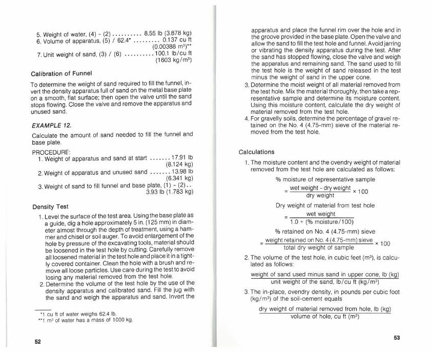
5. Weight of water, (4) - (2). 8.55 lb (3.878 kg)6. Volume of apparatus, (5) / 62.4* 0.137 Cu ft
(0.00388 m3)**7. Unit weight of sand, (3) / (6) 100.1 lb/cu ft
(1603 kg/m3)
Calibration of Funnel
To determine the weight of sand required to fill the funnel, invert the density apparatus full of sand on the metal base plateon a smooth, flat surface; then open the valve until the sandstops flowing. Close the valve and remove the apparatus andunused sand.
EXAMPLE 12.
Calculate the amount of sand needed to fill the funnel andbase plate.
PROCEDURE:1. Weight of apparatus and sand at start 17.91 lb
(8.124 kg)2. Weight of apparatus and unused sand 13.98 lb
(6.341 kg)3. Weight of sand to fill funnel and base plate, (1) - (2)..
3.93 lb (1 .783 kg)
Density Test
1. Level the surface of the test area. Using the base plate asa guide, dig a hole approximately 5 in. (125 mm) in diameter almost through the depth of treatment, using a hammer and chisel or soil auger. To avoid enlargement of thehole by pressure of the excavating tools, material shouldbe loosened in the test hole by cutting. Carefully removeall loosened material in the test hole and place itin a tightly covered container. Clean the hole with a brush and remove all loose particles. Use care during the test to avoidlosing any material removed from the test hole.
2. Determine the volume of the test hole by the use of thedensity apparatus and calibrated sand. Fill the jug withthe sand and weigh the apparatus and sand. Invert the
*1 cu ft of water weighs 62.4 lb.~1 m3 of water has a mass of 1000 kg
apparatus and place the funnel rim over the hole and inthe groove provided in the base plate. Open the valve andallow the sand to fill the test hole and funnel. Avoid jarringor vibrating the density apparatus during the test. Afterthe sand has stopped flowing, close the valve and weighthe apparatus and remaining sand. The sand used to fillthe test hole is the weight of sand released in the testminus the weight of sand in the upper cone.
3. Determine the moist weight of all material removed fromthe test hole. Mix the material thoroughly, then take a representative sample and determine its moisture content.Using this moisture content, calculate the dry weight ofmaterial removed from the test hole.
4. For gravelly soils, determine the percentage of gravel retained on the No. 4 (4.75-mm) sieve of the material removed from the test hole.
Calculations
1 . The moisture content and the ovendry weight of materialremoved from the test hole are calculated as follows:
% moisture of representative sample= wet weight-dryweight ~ 100
dry weight
Dry weight of material from test holewet weiqht
1.0 + (% moisture/100)% retained on No. 4 (4.75-mm) sieve
= weight retained on No.4(4.75-mm) sieve 100total dry weight of sample
2. The volume of the test hole, in cubic feet (m3), is calculated as follows:
weight of sand used minus sand in upper cone, lb (kg)unit weight of the sand, lb/cu ft (kg/rn3)
3. The in-place, ovendry density, in pounds per cubic foot(kg/rn3) of the soil-cement equals
dry weight of material removed from hole, lb (kg)volume of hole, Cu ft (m3)
5253

Rubber-Balloon MethodAs with the sand-cone method, the density hole is dug and allthe material removed is placed in a container and its dryweight determined. The volume of the hole is then determineddirectly using a calibrated apparatus containing water. A pressure bulb exerts pressure on the water and a rubber ballooncontaining water is forced into the confines of the density hole(ASTM D21 67, AASHTO T205). The difference between theinitial and final water volume readings is the volume of thehole. Like other methods, the rubber-balloon method has limitations and care must be taken in running the test.
Record of Field Density TestsA record of density and depth data should be kept. The procedure for keeping records is illustrated on the form sheet (Fig.A-3) in the Appendix.
Correcting for Differences in Gravel ContentOccasionally, field densities of soil-cement containing largepercentages of gravel do not agree with the moisture-densitytest results. The percentage of gravel in the material takenfrom the density hole may be different from that in the sampleused in the field moisture-density test. This difference in density can be corrected by using Fig. 28. A similar chart is givenin AASHTO T224.
Fig. 27. Measuring depth oftreatment through the densityhole. A phenolphthalein solutioncan be squirted down the sideof a freshly cut face of newlycompacted soil-cement. Thesoil-cement will turn pinkish-redwhile the untreated subgradematerial will retain itsnatural color.
~- Q ~() ~N N N N
n~I
0
B ro/q~ ~ ~G
Fig. 28. Density correction chart for differences in gravel content.
aAoJb ~o •j~ ds ~iI~8N
N NI I
~ ~U, ~ ~
~ .a_ ~+0 55 “~ ~—
U U~” 5~Z
~LX ~& ~ U,
0 0
/
0+
S
E5
54 55

EXAMPLE 13.
Find density corrected for gravel content.
GIVEN:Percentage of gravel larger than No.4(4.75-mm) sieve in fieldmoisture-density test sample 18%Percentage of gravel larger than No. 4 (4.75-mm) sieve insample from field density hole 11%Bulk specific gravity of gravel 2.50*Maximum density from field moisture-density curve determined on sample containing 18% gravel 120.0 lb per
cubic foot (1922 kg/m3)
PROCEDURE:On the grid (Fig. 28) locate the intersection of 120.0 lb percubic foot (1922 kg/m3) dry density and 18% gravel. With astraightedge, intersect this point and the specific gravity of2.50, then extend this line until it intersects the vertical line onthe grid representing 11 % gravel. Project this point horizontally to the dry density scale on the left edge: 118.2 lb per cubicfoot (1893 kg/m3)
ANSWER:The density of 118.2 lb per cubic foot (1893 kg! m3) is the corrected theoretical maximum dry density of the field moisture-density testforasample containing 11% gravel instead of 18%gravel. The in-place dry density of the material tested shouldbe compared to this corrected density.
After the density determination is made, the compacteddepth is measured. The depth of treatment is usually quiteapparent because of the difference in color between the sub-grade and the soil-cement mixture. However, it is sometimesdifficult to distinguish the bottom of treatment by color, inwhich case water is poured into the density hole and allowedto stand. The subgrade will be softened while the full depth oftreatment will remain firm. The bottom of treatment can then
*Bulk specific gravity of gravel (pycnometer method) = B +~ ~
A = ovendry weight of gravel, gramsB = saturated surface-dry weight of gravel, gramsY = weight of pycnometer filled with water, gramsZ = weight of pycnometer and saturated surface-dry gravel, filled
with water, grams
be determined by probing with a pointed instrument.A phenolphthalein solution can be squirted down the side ofa freshly cut face of newly compacted soil-cement. The soil-cement will turn pinkish-red while the untreated subgradematerial will retain its natural color.
CuringSoil-cement at optimum moisture contains sufficient moisturefor adequate cement hydration. After final compaction, amoisture-retaining cover is placed over the soil-cement topermit the cement to hydrate. Moist soil-cement is cured withbituminous material, but other materials such as waterproofpaper or plastic sheets, wet straw or sand, fog-type waterspray, and wet burlap or cotton mats are entirely satisfactory.The bituminous materials most commonly used are emulsifiedasphalt SS-1, RC-250, MC-250, and RT-5.
The rate of application varies from 0.15 to 0.30 gal persquare yard (0.7 to 1 .4 L!m2). Before the bituminous materialis applied, the surface of the soil-cement should be moist andfree of dry, loose material. In most cases a light application ofwater precedes the bituminous cure.
When the air temperature is expected to reach the freezingpoint, the soil-cement should be protected from freezing for 7days after its construction and until it has hardened.
( ‘I
-.7..
Fig. 28.Water truck applies light water spray to soil-cement surface to maintain moisture throughout compaction, finishing, andcuring operations.
56 57

AppendixOpening to TrafficCompleted portions of soil-cement can be opened immediately to local traffic and to construction equipment providingthe soil-cement has hardened sufficiently to prevent marringor distorting of the surface, and providing the curing materialis not impaired. If the bituminous moisture-retaining coverhas not dried sufficiently to prevent pick-up, sufficient sand orgrandular cover should be applied.
MaintenanceSpecifications require that the contractor maintain the soil-cement in good condition until all work has been completed andaccepted. Any defects that occur should be repaired immediately by replacing the soil-cement for the full depth of treatment.Areas deficient in thickness should also be remedied by replacing the material for full depth of treatment rather than by addinga thin layer of soil-cement to the completed work.
Equipment for Field Tests1. Field laboratory.2. Two-burner field stove.3. Split moisture-density mold and rammer(1 /30-cu-ft [943-
cm3] mold; sleeved 5Y2-lb [2.5-kg] rammer).4. Balance with weights, 750-g capacity.5. Scale with weights, 20-lb (9-kg) capacity.6. Three 3x3-ft (lxi -m) pieces of canvas.7. Spring scale, 100-lb (45-kg) capacity.8. Set of 8-in-diameter (200-mm) sieves: 2 in. (50 mm), 34 in.
(19 mm), and No. 4 (4.75 mm).9. Sand-cone density apparatus with supply of dry sand of
known unit weight.10. A 5-in.-diameter (125-mm) soil auger and No. 2 short-
handled square-pointed shovel.11. Hammer and two 1-in. (25-mm) mason’s chisels.12. Six tin pie plates and six ‘h-gal (2-L) containers with lids.13. Two 1 0-in-diameter (250-mm) frying pans.14. A 100-mI glass graduated cylinder.*-5..A 10-in. (250-mm) butcher knife, 12-in. (300-mm) steel
straightedge, and 10-in. (250-mm) trowel.16. Two 1 2-qt (11 -L) pails, two large spoons, and a 2-in. (50-
mm) paint brush.17. A 5x5-ft (1 .5x1 .5-rn) canvas sample cloth.18. Ruler and 50-ft (15-rn) tape.
58 59

STATE
ROUTE COUNTY
DATE
PROJECT NO
flflATIflN
C
Moisture-Density Relations(SI Units)
—~MOISTURE CONTENT.%
Inspector
MOISTURE CONTENT. %
Inspector
Fig. A-i. Form sheet for recording field moisture-density data(U.S. customary units).
Fig. A-2. Form sheet for recording field moisture-density data(SI units).
Moisture-Density Relations(U.S. Customary Units)
STATION:_________________________ REMARKS:
TESTNUMBER 1 2(1) Wet weight specimen + mold lb
(2) Weight 01 mOld lb
(3) Net wet weight specimen (I) — (2) lb
(4) Volume of mold Cu It
(5) Wet density (3) — (4) lb/cu It
(6) Wet weight sample + contamer g —
(7) Dryweight sample + container 5
(8) Weight of moisture (6) — (7)
(9) We:ghtotcontainer g —
(IS) NetweightdrysarnPle(7( — (9) g —
(it) Moisturecofltenti)8) (iO))iOO
(12) Drydensity)5) [I * )1t)) lb/cu It —
PROJECT: PROJECT NO.:
STATION: REMARKS:____________________________
TEST NUMBER I 2 3 4(I) Wet mass specimen + mold kg
(2) Mass of mold kg
(3) Net wet mass spec:men (1) —(2) kg
(4) Volume of mold cm’
(5) Wet densdy (3) • (4) kg/mu
(6) Wet mats sample + container g
(7) Dry mass sample + container
(8) Mass of moisture (6) —(7)
(9) Mass of container
(10) Net mass dry sample (7(—)9)
(it) Moisture content ((8) • (10)] 100
(12) Dry density (5) * (1 + (11() kg/rn’
S
0)
0
Maoimum Density
lb/cu If
Optimum Mc,sture
Mammum Density
kyIm’
Optimum Moislure
60 61

LOCATION
PROJECT
REMARKS
Field Density
DATE
PROJECT NO
LOCATION
PROJECT
REMARKS
method.
Field Density
DATE
PROJECT NO
Irapector
Wee WeIght of Sereplefrom Test Hole
(I) Wet WeightotSamPle+Pe1’ lb
121 Weightof Pen lb kg
(31 Wet Weight 01 Sample From Test Hole (1) — (2) lb kg
Holame Detemileetlen of Test Hole
4 lnSalWeightOtApParatuO~ Sand E
S Final Weightof Apparatus + Sand lb kg
(El Weight 01 Sand Used (4) — (SI lb . kg
(7) Less Weight at Sand in Furerel lb kg
1W Weightot Sand Uead to FilITest Hole (6) — (7) lb kg
(5) UnitWeightotSand(asCalibrated( lb/cuR ............kglmi
(IS) i~urneotTestHnle(g( (9) cuR .______.cm’
Meletere Contest Detenolsetlon
(111 WetWeightotbalnPle+Cmttorrem
(12) Dry Weight of Sample + Container
)t3( WeighlolCorrtainer g
(14) WeigbtotMoloture(l1( (12)
tb) DryWeIghlotSaInPta(t2( (131
(16) MmstureCOntentStd( (tb((ISO
Dermeftp
(Ill DryWaightotbanrplehOrrrTestHxle(3( — It + (16)9 lb kg
hg) Dry Density(17) — (IS) lblcutt kg/me
(19) Maximum Dry DensityItrom Rest M-D relebmis) Ibicu 9 kglm’
(25) DegreeOfCompactixflSlo) (15)1120
Depth
(Sm) Depth at Treabnent eon
emseede,.dec?d
WeaWeIglitot Sample trese Test Hole
(I) Wet Weightol Sample + Pan 1203 lb 5.965 kg
(2) WeightolPan 3.10 lb 1406 kg
(3) WetWeightxlSampleFmmTestHole(1) (2) 603 lb 4459 kg
*tume Determleag(ae of Tees Hole
Id) lnibalWeightofApparatuo.Sand 1791 lb 6124 kg
b) Final Weight at Apparatus + Sand 646 lb 2 030 kg
(61 WeighrxlbondUsad(4(—)b( 1149 lb 6194 kg
)7( LessWeigktotgandinpunnral 3.93 lb 1.763 kg
(6) WeighrotSandUsedroFieTeothtole)6(—(7) 792 lb 9411 kg
(51 Unit Weight xl Sand (at catbraled) 100 I lb/ca g 1603 kg/mr
(IS) SalumeofTeetHole(9) (9) 00791 cuR 213 cmi
Molotare Coolest Determln.gloe
(ml) Wet WeightotSample + Container 1210
(12) Dry Weightof Sample 4 Container 1106
(13) Weight of Coritoner 376
(ld) Weight of Moisture )tt) (12) 04
113) DryWeightotSemple)t2) 113) 750
(16) MoistumCorrrenr (ld( (151) 150 II 2 %
Denety
(17) DryWeighrolSamplehmnTesrHole(3) .-(t + )rgr( 004 lb 4 010 kg
)16( Dry Density (17) + (IS) 1177 lb/caR 1003 kglm’
1101 Manimam Dry Deosby(fromlehtM-Drelatixss) 20.0 Ib/oult 1925 kg/m3
(20) DegreeotCompactionplt8) (t9)(rSS 90 %
Depth
)Sr) DepthntTmabnent 6-114 n 109 mm
Fig. A-3. Form sheet for in-place density test—sand-Conemethod.
Fig. A-4. Example of in-place density test data—sand-cone
62 63

Related Publications
The following publications are available for purchasefrom the Portland Cement Association.
Cement-Treated Aggregate Base, SR221PCA Soil Primer, EBOO7Properties and Uses of Cement-Modified Soil, 1411Soil-Cement Construction Handbook, EBOO3Soil-Cement Laboratoiy Handbook, EB052Suggested Specifications for Soil-Cement Base
Course, lSOO8Thickness Design for Soil-Cement Pavements, EB068
The publications listed above can be obtained by writing,calling, or faxing Customer Service, Portland CementAssociation, 5420 Old Orchard Road, Skokie, Illinois60077-1083, Phone: 847.966.6200, Fax: 847.966.9666 orfor a complete listing of all our products visit our Web siteat: www.portcement.org.
This publication is intended SOLELY for use by PROFESSIONAL PERSONNEL who are competent to evaluate the significance and limitationsof the information provided herein, and who will accept total responsibility for the application of this information. The portland CementAssociation DISCLAIMS any and all RESPONSIBILITY and LIABILITY forthe accuracy of and the application of the information contained in thispublication to the full extent permitted by law.
Warning: Contact with wet (unhardened) concrete, mortar, cement, orcement mixtures can cause SKIN IRRITATION, SEVERE CHEMICALBURNS (THIRD-DEGREE), or SERIOUS EYE DAMAGE. Frequent exposure may be associated with irritant and/or allergic contact dermatitis.Wear waterproof gloves, a long-sleeved shirt, full-length trousers, andproper eye protection when working with these materials. If you have tostand in wet concrete, use waterproof boots that are high enough to keepconcrete from flowing into them. Wash wet concrete, mortar, cement, orcement mixtures from your skin immediately. Flush eyes with clean waterimmediately after contact. Indirect contact through clothing can be asserious as direct contact, so promptly rinse out wet concrete, mortar,cement, or cement mixtures from clothing. Seek immediate medicalattention if you have persistent or severe discomfort.
]
KEYWORDS: calibration, cement application, compaction, curing,density, equipment, finishing, inspection, maintenance, mixingplants, moisture, moisture density, pulvenzation, site preparation,soil-cement processing, soil identification, soil materials, uniformity,water application.
ABSTRACT: Describes procedures for inspecting soil-cement con- Istruction. Sample problems are given that show typical calculationsrequired for computing material quantities, and for field test. Tablesand charts to simplify these calculations are included.
REFERENCE: Soil-Cement Inspector’s Manual (PAO5O.03),Portland Cement Association, 2001.
64