Embed Size (px)
Citation preview

Project Report on
SOLAR POWERED LAKE AND POND AERATION SYSTEM
(Approved by KSCST)
VISVESVARAYA TECHNOLOGICAL UNIVERSITY Jnana Sangama, Belagavi
Submitted in partial fulfillment of the requirements for the award of degree of
Bachelor of Engineering in Mechanical Engineering
Submitted By
R. Ameen Ahmed 1CE13ME057
Mohammed Zeeya Mudnal 1CE13ME044
S. Sanjay Kumar 1CE13ME065
Shivappa 1CE13ME074
Under the guidance of
Mr. HARSHA VARDHAN U Assistant professor
Department of Mechanical Engg .
CEC, Bangalore
DEPARTMENT OF MECHANICAL ENGINEERING
CITY ENGINEERING COLLEGE
Vasanthapura, Kanakapura Main Road Bangalore - 560 062
2016-17

CITY ENGINEERING COLLEGE Vasanthapura, Kanakapura Main Road Bangalore - 560 062
Department of Mechanical Engineering
Certificate
Certified that the project work entitled “SOLAR POWERED LAKE AND POND
AERATION SYSTEM” is a bonafide work carried out by Mr. R. Ameen Ahmed
(1CE13ME057), Mr. Mohammed Zeeya Mudnal (1CE13ME044), Mr. Sanjay Kumar
(1CE13ME065), and Mr. Shivappa (1CE13ME074) in partial fulfillment for the award of
Bachelor of Engineering in Mechanical Engineering of the Visvesvaraya Technological
University, Belagavi during the year 2016-17. It is certified that all corrections / suggestions
indicated for internal assessment have been incorporated in the Report deposited in the
departmental library. The project has been approved as it satisfies the academic requirements
in respect of Project work prescribed for the said Degree.
Signature of Guide Signature of HOD
(Mr. Harsha Vardhan U) (Uma T.R)
Signature of Principal
(Dr. Bharathesh T.P)
External Viva
Name of the Examiners Signature with Date
1.
2.

DECLARATION
We,Mr.R.Ameen.Ahmed(1CE13ME057),Mr.Mohammed.Zeeya.Mudnal
(1CE13ME044), Mr.S.Sanjay.Kumar (1CE13ME065), Mr.Shivappa (1CE13ME074)
hereby declare that the project work entitled “SOLAR POWERED LAKE AND POND
AERATION SYSTEM” has been independently carried out by us under the guidance of
Mr. HARSHA VARDHAN U, Assistant professor, Department of Mechanical
Engineering, City Engineering College, Bangalore, in partial fulfillment of the
requirements of the Degree in Bachelor Of Engineering in Mechanical Engineering
Visvesvaraya Technological University, Belagavi.
We further declare that we have not submitted this report either in part or in full to any
other university for the award of any degree.
NAMES USN NO SIGNATURE
R.AMEEN.AHMED 1CE13ME057………………………………..
MOHAMMED.ZEEYA.MUDNAL 1CE13ME044…………………………..........
S.SANJAY.KUMAR 1CE13ME065………………………………...
SHIVAPPA 1CE13ME074………………………………..
Place: Bangalore
Date:
ABSTRACT
Water aeration and filtration is a method to improve the water quality in a lake or pond by
adding oxygen to the water and filtering it. As water aeration systems are often located in
remote locations, Solar panels are ideal for powering these systems. This paper describes a
water aeration and filtration system powered by Solar panels. The portable nature of this
system permits the owner to conveniently relocate the system aerate and filter bodies of
water as needed.
The present invention is a solar powered aeration and filtration system that
incorporates a battery. The device can be used for improvement of water bodies for use in
aqua culture systems, reservoirs, fish tanks, lakes, and ponds alike. The device doesn’t
require connection to the electrical power grid and may be used in any location. Further,
the device can be used during periods of low oxygen content and filtration of polluted water
bodies. Increased efficiency can be obtained by matching the pump size, solar panels,
filters, batteries according to the area of the water boy to be covered.
(i)

ACKNOWLEDGMENTS
We express our happiness and gratitude for having completed the project titled “SOLAR
POWERED LAKE AND POND AERATION SYSTEM” without any hindrances.
Our sincere thanks to the management of CEC, who have strived to provide the best to the
students in all aspects.
We express our deep gratitude to Mr. HARSHAVARDHAN U, Assistant professor, Dept.
of Mechanical Engineering, City Engineering College, our internal guide for his inspiration
and guidance to complete the project.
We would also like to thank our Head of the Department, Mrs. UMA T R, City
Engineering College, Bangalore, for the encouragement that she gives us to achieve higher
and greater things in life.
We fall short of words to thank and express gratitude to our beloved principal,
Dr. BHARATHESH T P, City Engineering College, Bangalore.
I would like to extend my sincere gratitude to all the respected faculty of the Department
of Mechanical Engineering for their extreme support which helped me in completing the
project successfully.
It is my pleasure to acknowledge my family and friends who helped me in completing the
project successfully.
(ii)

LIST OF CONTENTS
CERTIFICATE…………………………………………………………… i
DECLARATION………………………………………………………….. ii
ABSTARCT……………………………………………………………….. iii
ACKNOWLEDGEMENT………………………………………………... iv
CHAPTER 1……………………………………………………………….. 1
1.1 INTRODUCTION…………………………………………………….. 2
1.2 SHOULD WATER BE CHLORINATED…………………………… 3
1.3 REDUCING THE CONCENTRATION OF
CHEMICALS IN WATER………………………………………….. 3
CHAPTER 2………………………………………………………………. 4
2.1 BOILING…………………………………………………………….... 5
2.2 HOUSEHOLD SLOW SAND FILTER……………………………... 6
2.3 WATER CHLORINATION AT HOUSEHOLD LEVEL…………. 8
2.4 STORAGE AND SEDEMENTAION……………………………….. 9
CHAPTER 3…………………………………………………………….... 12
3.1 POTABLE WATER PURIFICATION…………………………….. 13
3.2 ADDITIONAL TREATMENT OPTIONS………………………… 13
CHAPTER 4……………………………………………………………... 17
4.1 SAND FILTER………………………………………………………. 19
4.2 WATER CHOLRINATION………………………………………… 20
4.3 CLEAN COAL TECHNOLOGY…………………………………... 22
4.4 SAND BED FILTRATION CONCEPT…………………………… 22
CHAPTER 5……………………………………………………………... 24
5.1 SOURCES OF WATER…………………………………………...... 26
5.2 PRE-TREATMENT………………………………………………… 27
5.3 COAGULATION AND FLOCCULATION………………………. 28
5.4 SEDIMENTATION…………………………………………………. 29
5.5 SLUDGE STORAGE AND REMOVAL…………………………... 29

5.6 FLOC BLANKET CLARIFIERS…………………………………...... 30
5.7 DISSOLVED AIR FLOTATION……………………………………... 30
5.8 RAPID SAND FILTER………………………………………………... 30
5.9 SLOW SAND FILTERS……………………………………………...... 31
5.10 MEMBRANE FILTRATION………………………………………… 32
CHAPTER 6……………………………………………………………….... 34
6.1 ELECTRICAL DC MOTORS………………………………………… 35
6.2 FISH TANK…………………………………………………………….. 38
6.3 GEARED DC MOTOR……………………………………………….... 38
6.4 L293D DC MOTOR DRIVER IC……………………………………… 40
6.5 LIQUID CRYSTAL DISPLAY………………………………………... 42
6.6 LIGHT SENSORS……………………………………………………… 44
CHAPTER 7………………………………………………………………… 49
7.1 PIC MICROCONTROLLER………………………………………….. 50
7.2 POWER SUPPLY CIRCUIT…………………………………………. 51
7.3 RESISTORS…………………………………………………………… 53
7.4 SOLAR PANEL……………………………………………………….. 56
7.5.1 LEAD ACID BATTERY……………………………………………. 58
7.5.2 VRLA BATTERY…………………………………………………… 58
7.6WATER PUMP MOTOR……………………………………………… 59
ADVANTAGES……………………………………………………………… 62
APPLICATIONS…………………………………………………………….. 62
CONCLUSION………………………………………………………………. 63
BIBLOGRAPHY…………………………………………………………….. 64

LIST OF FIGURES
FIG.NO
CONTENTS
PG.NO
1. BOILING TECHNOLOGY 5
2. HOUSEHOLD FLOWS AND FILTER 6
3. DOMESTIC CHLORINATION 9
4. TYPICAL SMALL DC MOTOR 35
5. DC SERVO MOTOR 37
6. GLASS 38
7.1 GEARD DC MOTOR EXTERNAL STRUCTURE 39
7.2 GEARD DC MOTOR INTERNAL STRUCTURE 39
8.1 L293D PIN CONFIGURATION 41
8.2 L293D BASED MOTOR DRIVER 42
9.1 LCD DISPLAY UNIT 42
9.2 INTERNAL WORKING LCD UNIT 43
10.1 TYPICAL LDR 44
10.2 THE LIGHT DEPENDENT RESISTOR CELL 45
11. LIGHT LEVEL SENSING CIRCUIT 46
12. PHOTO-DIODE CIRCUIT 47
13. PHOTOVOLTAIC CELL 47
14. PHOTOVOLTAIC SOLAR CELL 48
15. PIC MICROCONTROLLER 51
16. TRANSFORMER 52
17.1 POWER SUPPLY CIRCUIT 53
17.2 POWER SUPPLY CIRCUIT ALONG WITH
RGULATOR
53
18.1 CARBON RESISTOR 54
18.2 FILM RESISTOR 55
18.3 WIRE WOUND RESISTOR 56
19. OPERATION OF SOLAR PANEL 57
20. VRLA BATTERY 59

21. WATER PUMP MOTOR 59
22. BLOCK DIAGRAM OF SOLAR POWERED LAKE
AND POND AERATION SYSTEM
60
LIST OF TABLES
TABLE 1 LIST OF MATERIALS 61

DEPT OF MECHANICAL, CEC 2016-2017 Page 1
SOLAR POWERED LAKE AND POND AERATION SYSTEM
CHAPTER 1
INTRODUCTION

DEPT OF MECHANICAL, CEC 2016-2017 Page 2
SOLAR POWERED LAKE AND POND AERATION SYSTEM
1.1 INTRODUCTION:
Water can be contaminated by the following agents:
Pathogens – disease-causing organisms that include bacteria, amoebas and viruses, as
well as the eggs and larvae of parasitic worms. Harmful chemicals from human
activities (industrial wastes, pesticides, fertilizers). Chemicals and minerals from the
natural environment, such as arsenic, common salt and fluorides. Some non-harmful
contaminants may influence the taste, smell, colour or temperature of water, and make it
unacceptable to the community. Water from surface sources is often contaminated by
microbes, whereas groundwater is normally safer, but even groundwater can be
contaminated by harmful chemicals from human activities or from the natural
environment. Rainwater captured by a rooftop harvesting system or with small
catchment dams is relatively safe, provided that the first water is allowed to flow to
waste when the rainy season starts. The amount of water to be treated should also be
assessed. This can be estimated by assuming that each person will need a minimum of
20–50 litres of water a day for drinking, cooking, laundry and personal hygiene. A
community should be consulted when choosing a water-treatment system and should be
made aware of the costs associated with the technology. In particular, community
members should be made aware of the behavioural and/or cultural changes needed to
make the system effective over the long-term and thus be acceptable to them.
Communities may also need to be educated about protecting water sources from animal
or human contamination, and mobilized. It should be emphasized that all the positive
effects of a water-treatment system could be jeopardized if the water is not drawn, stored
and transported carefully and hygienically. The Fact Sheets in this section deal with both
community and household methods for treating water. Whereas the following household
and community water-treatment technologies are described in greater detail:
Household water-treatment systems
boiling;
Household slow sand filter;
Domestic chlorination.
Community water-treatment systems
Storage and sedimentation;
DEPT OF MECHANICAL, CEC 2016-2017 Page 3
SOLAR POWERED LAKE AND POND AERATION SYSTEM
up-flow roughing filter;
slow sand filtration;
Chlorination in piped water-supply systems.
1.2 Should water be chlorinated?
The water-treatment methods described above can reduce the number of pathogens in
water, but do not always eliminate them completely. And although boiling and solar
disinfection are effective, the methods are impractical with large volumes of water. In
contrast, chemical disinfection inactivates pathogenic organisms and the method can be
used with large volumes of water. Chlorine compounds usually destroy pathogens after
30 minutes of contact time, and free residual chlorine (0.2–0.5 mg per litre of treated
water) can be maintained in the water supply to provide ongoing disinfection. Several
chlorine compounds, such as sodium hypochlorite and calcium hypochlorite, can be used
domestically, but the active chlorine concentrations of such sources can be different and
this should be taken into account when calculating the amount of chlorine to add to the
water. The amount of chlorine that will be needed to kill the pathogens will be affected
by the quality of the untreated water and by the strength of the chlorine compound used.
If the water is excessively turbid, it should be filtered or allowed to settle before
chlorinating it.
1.3 Reducing the concentration of chemicals in water
1.3.1 Iron and manganese:
Water collected from boreholes can have a high concentration of iron (greater than 0.3
mg/l, the WHO guideline value). This can be the result of a naturally high iron content in
the soil, or the result of corrosion (from iron pipes, borehole casings and screens). The
iron gives the water an unpleasant metallic taste and odour, stains laundry and white
enamel on sinks and bowls, and discolours food. Although such levels of iron are known
to be harmful, the undesirable properties can cause communities to accept contaminated
water that has no taste, instead of safe water that has a metallic taste. Most of the iron
can be removed simply, by aerating the water and filtering it through sand and gravel.
The sand and gravel used in the filters will need to be cleaned periodically.

DEPT OF MECHANICAL, CEC 2016-2017 Page 4
SOLAR POWERED LAKE AND POND AERATION SYSTEM
CHAPTER 2
EXISTING METHODS

DEPT OF MECHANICAL, CEC 2016-2017 Page 5
SOLAR POWERED LAKE AND POND AERATION SYSTEM
2.1 Boiling:
Heating water is an effective way to kill the microorganisms in it. WHO recommends
that the water be brought to a vigorous boil? This will kill, or inactivate, most organisms
that cause diarrhoea. High turbidity does not affect disinfection by boiling, but if the
water is to be filtered, this must be done before boiling. For household use, water is
mostly boiled in a pot on a stove. If it is not to be stored in the same pot in which it was
boiled, the water should be poured into a clean storage container immediately after
boiling, so that the heat of the boiled water will kill
Most of the bacteria in the storage container. Fuel costs, and the time involved in boiling
and cooling the water, limit the usefulness of this method. A study in Bangladesh
estimated it would cost 7% of the average family budget to boil all the water for the
village (Gilman & Skill corn, 1985). Also, fuel prices continue to rise in most parts of the
world.
Fig.1 BOILING TECHNOLOGY
Main O&M activities:
Disinfection of water by heating is normally carried out within the household.
Usually, the water is brought to a rolling boil in a clean pot on a stove, sometimes with
herbs added to the water. The water is then allowed to cool down. Care must be taken not
to contaminate the water after boiling. When fuel has to be collected or treated, this may
take up a lot of a household’s time. In the kitchen, everyday maintenance includes
checking the stove and pots. The frequency with which the stove will need to be repaired
or replaced will depend on stove design, the quality of materials and workmanship, and

DEPT OF MECHANICAL, CEC 2016-2017 Page 6
SOLAR POWERED LAKE AND POND AERATION SYSTEM
intensity of use. Pots are seldom repaired, and earthen pots often need to be replaced.
The necessary skills for O&M activities are usually available in all communities.
Potential problems:
a. The water becomes decontaminated after boiling;
b. Fuel for boiling the water is scarce and, consequently, expensive;
c. Boiled water tastes flat – this may be corrected by adding herbs to the
water during boiling and not drinking it for six hours after it has been
boiled.
2.2 HOUSEHOLD SLOW SAND FILTER:
With a household slow sand filter, water is passed slowly downwards through a
bed of sand, where it is treated by a combination of biological, physical and chemical
processes. Fine particles in the water are filtered out by the sand, while microorganisms
grow on top of the sand
Filter and feed on bacteria, viruses and organic matter in the water. The filter can be
made of clean 200- litre steel barrels connected by hoses. The system consists of a raw-
water supply
Tank a filter tank and a clean water tank. A floating weir (that can be made of a bowl,
two small tubes and a hose) in the supply tank maintains a constant flow of water to the
top of the filter tank, where it is purified by passing downwards through a 45–60-cm bed
of washed sand and a 5-cm layer of fine gravel.
Fig.2 HOUSEHOLD FLOWS AND FILTER
The water flows through the sand at about 0.1 m/hour (1 m3 m-2 h-1). Water drains from
the bottom layer of the filter tank via a perforated tube and is led to a clean water-storage

DEPT OF MECHANICAL, CEC 2016-2017 Page 7
SOLAR POWERED LAKE AND POND AERATION SYSTEM
tank. To prevent oxidation of the steel barrels, they must be treated with cement mortar,
or any safe protective paint. Instead of steel barrels, tanks of fibrocement and other
materials can also be used. All tanks should be protected with lids. With good operation
and maintenance, a household slow sand filter produces water virtually free from
disease-causing organisms.
Initial cost: This depends on the local cost of used metal drums and other parts.
Yield: 380 litres per day for a tank 0.45 m in diameter.
Area of use: In places where drinking-water is unsafe and needs to be purified at
household level.
Manufacturers: Local artisans can make a household slow sand filter.
Main O&M activities:
For a slow sand filter to be effective, the flow of water must be maintained at a
constant 0.1 m/h. This provides the organisms in the filter with a stable flow of nutrients
and oxygen, and gives them time to purify the water. The flow rate of the water is
regulated by adjusting the floating weir. The raw-water storage tank must never be
allowed to empty. After a few weeks of operation, (or a few months, depending on the
quality of the raw water), the flow rate in the filter will become too low. At this point, 1–
2 cm of sand and organic material must be scraped off the top of the filter, washed, dried
in the sun and put aside. When the filter bed becomes too thin, the washed sand is
restored. This is done by taking some more sand from the top of the filter, adding back
the washed sand from previous operations, and then placing the sand just taken out on
top of the filter. Every year, the tanks must be checked for corrosion, and any leaks
repaired immediately. Occasionally, the clean-water tank may need to be disinfected
with chlorine, and a hose or tap may need to be repaired. As a household slow sand filter
is operated at family or household level, the organizational structure for operation
already exists. At least one person in each household should be trained in matters of
hygiene, and in the O&M of the filtering system. It may also be beneficial to have a local
laboratory to support and train families on water-quality issues.
1. Potential problems;
a. Water quality drops if the flow rate through the filter is too high;

DEPT OF MECHANICAL, CEC 2016-2017 Page 8
SOLAR POWERED LAKE AND POND AERATION SYSTEM
b. if the water flow is interrupted for more than a few hours, or if the surface
of the
2. Filter runs dry, beneficial microorganisms in the filter may die and the
effectiveness of the filter may be impaired;
a. excessive turbidity (>30 NTU) in the raw water can cause the filter to clog
rapidly,
3. in which case a pre-filter may be needed;
4. when water quality is very poor, harmful and bad-tasting products like ammonia
5. may be formed in the lower layers of the filter;
a. smooth vertical surfaces in the filter tank may cause short circuits in the
water
6. flow, producing badly-filtered water;
a. in some regions, sand is expensive or difficult to get – as an alternative,
other
7. Materials such as burnt rice husks can be used.
2.3 WATER CHLORINATION OF HOUSEHOLD LEVEL:
Chlorination of water at household level can be used as an emergency
measure or as part of everyday life. When water quality cannot be trusted, a carefully
measured amount of concentrated chlorine solution is added to a container with a
known amount of clear water. The mixture is stirred and left for at least 30 minutes,
to let the chlorine react and oxidize any organic matter in the water. After this, the
water is safe to drink. The amount of chlorine needed depends mainly on the
concentration of organic matter in the water and has to be determined for each
situation. After 30 minutes, the residual concentration of active chlorine in the water
should be between 0.2–0.5 mg/l, which can be determined using a special test kit.
The concentrated chlorine solution can be made of clear water and chlorine-
producing chemicals, such as bleaching powder, sodium hypochlorite, or organic
chlorine tablets.

DEPT OF MECHANICAL, CEC 2016-2017 Page 9
SOLAR POWERED LAKE AND POND AERATION SYSTEM
Fig.3 Domestic chlorination using a chlorine tablet
It can be prepared at household level, but also in larger quantities and distributed among
the households. A concentrated chlorine solution should be used within a relatively short
time (defined according to the compound used) before it loses its strength. In some cases,
chlorine-producing chemicals are added directly added to the water, without prior
dilution. Some chlorine products come in combination with a flocculent to help settle
suspended material in the water.
Initial cost: The costs depend on the type of chlorine compound used, the quality of the
untreated water, etc.
Yield: About 150–1400 m3 treated water per kg of dry chemical, depending on the water
quality and the strength of the concentrated chemical.
Area of use: Wherever drinking-water needs to be disinfected at household level, and
chlorine is available.
Trademarks: Chlor-dechlor; Dazzle; Halamid; Halazone; Javelle; Milton; Regina;
Zonite
And many others.
2.4 STORAGE AND SEDIMENTATION:
The quality of raw water can be improved considerably by storage. During storage, non-
colloidal, suspended particles slowly settle to the bottom of a storage tank, and solar
radiation will kill some of the harmful organisms in the water. Schistosoma larvae, for
example, will die after storage for at least 48 hours. In contrast, colloidal particles remain
in suspension. The smaller the suspended particles, the longer the water needs to be
retained in the reservoir. If the suspended matter precipitates very slowly, chemicals can
DEPT OF MECHANICAL, CEC 2016-2017 Page 10
SOLAR POWERED LAKE AND POND AERATION SYSTEM
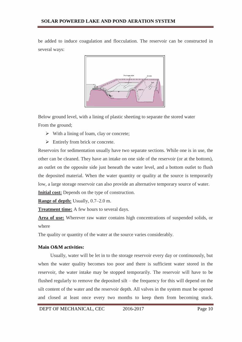
be added to induce coagulation and flocculation. The reservoir can be constructed in
several ways:
Below ground level, with a lining of plastic sheeting to separate the stored water
From the ground;
With a lining of loam, clay or concrete;
Entirely from brick or concrete.
Reservoirs for sedimentation usually have two separate sections. While one is in use, the
other can be cleaned. They have an intake on one side of the reservoir (or at the bottom),
an outlet on the opposite side just beneath the water level, and a bottom outlet to flush
the deposited material. When the water quantity or quality at the source is temporarily
low, a large storage reservoir can also provide an alternative temporary source of water.
Initial cost: Depends on the type of construction.
Range of depth: Usually, 0.7–2.0 m.
Treatment time: A few hours to several days.
Area of use: Wherever raw water contains high concentrations of suspended solids, or
where
The quality or quantity of the water at the source varies considerably.
Main O&M activities:
Usually, water will be let in to the storage reservoir every day or continuously, but
when the water quality becomes too poor and there is sufficient water stored in the
reservoir, the water intake may be stopped temporarily. The reservoir will have to be
flushed regularly to remove the deposited silt – the frequency for this will depend on the
silt content of the water and the reservoir depth. All valves in the system must be opened
and closed at least once every two months to keep them from becoming stuck.

DEPT OF MECHANICAL, CEC 2016-2017 Page 11
SOLAR POWERED LAKE AND POND AERATION SYSTEM
Occasionally, the valves may need to be repaired or replaced, and leaks in the reservoir
will have to be fixed. Apart from some help from the water users to clean the reservoir
after it has been flushed, the system requires little support from an established
organization to maintain it.

DEPT OF MECHANICAL, CEC 2016-2017 Page 12
SOLAR POWERED LAKE AND POND AERATION SYSTEM
CHAPTER 3

DEPT OF MECHANICAL, CEC 2016-2017 Page 13
SOLAR POWERED LAKE AND POND AERATION SYSTEM
3.1 PORTABLE WATER PURIFICATION:
Portable water purification devices and methods are available for disinfection and
treatment in emergencies or in remote locations. Disinfection is the primary goal, since
aesthetic considerations such as taste; odour, appearance, and trace chemical
contamination do not affect the short-term safety of drinking water.
3.2 ADDITIONAL TREATMENT OPTIONS:
1. Water fluoridation: in many areas fluoride is added to water with the goal of
preventing tooth decay. Fluoride is usually added after the disinfection process. In the
U.S., fluoridation is usually accomplished by the addition of hexafluorosilicic acid,
which decomposes in water, yielding fluoride ions.
2. Water conditioning: This is a method of reducing the effects of hard water. In
water systems subject to heating hardness salts can be deposited as the decomposition of
bicarbonate ions creates carbonate ions that precipitate out of solution. Water with high
concentrations of hardness salts can be treated with soda ash (sodium carbonate) which
precipitates out the excess salts, through the common-ion effect, producing calcium
carbonate of very high purity. The precipitated calcium carbonate is traditionally sold to
the manufacturers of toothpaste. Several other methods of industrial and residential water
treatment are claimed (without general scientific acceptance) to include the use of
magnetic and/or electrical fields reducing the effects of hard water [citation needed]
3. Plumb solvency reduction: In areas with naturally acidic waters of low
conductivity (i.e. surface rainfall in upland mountains of igneous rocks), the water may
be capable of dissolving lead from any lead pipes that it is carried in. The addition of
small quantities of phosphate ion and increasing the pH slightly both assist in greatly
reducing plumbo-solvency by creating insoluble lead salts on the inner surfaces of the
pipes.
4. Radium Removal: Some groundwater sources contain radium, a radioactive
chemical element. Typical sources include many groundwater sources north of the
Illinois River in Illinois. Radium can be removed by ion exchange, or by water

DEPT OF MECHANICAL, CEC 2016-2017 Page 14
SOLAR POWERED LAKE AND POND AERATION SYSTEM
conditioning. The back flush or sludge that is produced is, however, a low-level
radioactive waste.
5. Fluoride Removal: Although fluoride is added to water in many areas, some areas
of the world have excessive levels of natural fluoride in the source water. Excessive
levels can be toxic or cause undesirable cosmetic effects such as staining of teeth.
Methods of reducing fluoride levels are through treatment with activated alumina and
bone char filter media.
OTHER WATER PURIFICATION TECHNIQUES:
Other popular methods for purifying water, especially for local private supplies are listed
below. In some countries some of these methods are also used for large scale municipal
supplies. Particularly important are distillation (de-salination of seawater) and reverse
osmosis.
1. Boiling: Bringing it to its boiling point at 100 °C (212 °F), is the oldest and most
effective way since it eliminates most microbes causing intestine related diseases, but it
cannot remove chemical toxins or impurities. For human health, complete sterilization of
water is not required, since the heat resistant microbes are not intestine affecting. The
traditional advice of boiling water for ten minutes is mainly for additional safety, since
microbes start getting eliminated at temperatures greater than 60 °C (140 °F). Though the
boiling point decreases with increasing altitude, it is not enough to affect the disinfecting
process. In areas where the water is "hard" (that is, containing significant dissolved
calcium salts), boiling decomposes the bicarbonate ions, resulting in partial precipitation
as calcium carbonate. This is the "fur" that builds up on kettle elements, etc., in hard
water areas. With the exception of calcium, boiling does not remove solutes of higher
boiling point than water and in fact increases their concentration (due to some water
being lost as vapour). Boiling does not leave a residual disinfectant in the water.
Therefore, water that is boiled and then stored for any length of time may acquire new
pathogens.
2. Granular Activated Carbon filtering: a form of activated carbon with a high
surface area, adsorbs many compounds including many toxic compounds. Water passing

DEPT OF MECHANICAL, CEC 2016-2017 Page 15
SOLAR POWERED LAKE AND POND AERATION SYSTEM
through activated carbon is commonly used in municipal regions with organic
contamination, taste or odours. Many household water filters and fish tanks use activated
carbon filters to further purify the water. Household filters for drinking water sometimes
contain silver as metallic silver nanoparticle. If water is held in the carbon block for
longer periods, microorganisms can grow inside which results in fouling and
contamination. Silver nanoparticles are excellent anti-bacterial material and they can
decompose toxic halo-organic compounds such as pesticides into non-toxic organic
products.
3. Distillation involves boiling the water to produce water vapour. The vapour
contacts a cool surface where it condenses as a liquid. Because the solutes are not
normally vaporised, they remain in the boiling solution. Even distillation does not
completely purify water, because of contaminants with similar boiling points and
droplets of unvapourised liquid carried with the steam. However, 99.9% pure water can
be obtained by distillation.
4. Reverse osmosis: Mechanical pressure is applied to an impure solution to force
pure water through a semi-permeable membrane. Reverse osmosis is theoretically the
most thorough method of large scale water purification available, although perfect semi-
permeable membranes are difficult to create. Unless membranes are well-maintained,
algae and other life forms can colonize the membranes.
5. The use of iron in removing arsenic from water. See Arsenic contamination of
groundwater.
6. Direct contact membrane distillation (DCMD). Applicable to desalination.
Heated seawater is passed along the surface of a hydrophobic polymer membrane.
Evaporated water passes from the hot side through pores in the membrane into a stream
of cold pure water on the other side. The difference in vapour pressure between the hot
and cold side helps to push water molecules through.
7. Desalination – is a process by which saline water (generally sea water) is
converted to fresh water. The most common desalination processes are distillation and
reverse osmosis. Desalination is currently expensive compared to most alternative

DEPT OF MECHANICAL, CEC 2016-2017 Page 16
SOLAR POWERED LAKE AND POND AERATION SYSTEM
sources of water, and only a very small fraction of total human use is satisfied by
desalination. It is only economically practical for high-valued uses (such as household
and industrial uses) in arid areas.
8. Gas hydrate crystals centrifuge method. If carbon dioxide or other low molecular
weight gas is mixed with contaminated water at high pressure and low temperature, gas
hydrate crystals will form exothermically. Separation of the crystalline hydrate may be
performed by centrifuge or sedimentation and decanting. Water can be released from the
hydrate crystals by heating.
9. In Situ Chemical Oxidation, a form of advanced oxidation processes and
advanced oxidation technology, is an environmental remediation technique used for soil
and/or groundwater remediation to reduce the concentrations of targeted environmental
contaminants to acceptable levels. ISCO is accomplished by injecting or otherwise
introducing strong chemical oxidizers directly into the contaminated medium (soil or
groundwater) to destroy chemical contaminants in place. It can be used to remediate a
variety of organic compounds, including some that are resistant to natural degradation
10. Bioremediation is a technique that uses microorganisms in order to remove or
extract certain waste products from a contaminated area. Since 1991 bioremediation has
been a suggested tactic to remove impurities from water such as alkanes, perchlorates,
and metals. The treatment of ground and surface water, through bioremediation, with
respect to perchlorate and chloride compounds, has seen success as perchlorate
compounds are highly soluble making it difficult to remove. Such success by use of
Dechloromonas agitate strain CKB include field studies conducted in Maryland and the
Southwest region of the United States. Although a bioremediation technique may be
successful, implementation is not feasible as there is still much to be studied regarding
rates and after effects of microbial activity as well as producing a large scale
implementation method.

DEPT OF MECHANICAL, CEC 2016-2017 Page 17
SOLAR POWERED LAKE AND POND AERATION SYSTEM
CHAPTER 4

DEPT OF MECHANICAL, CEC 2016-2017 Page 18
SOLAR POWERED LAKE AND POND AERATION SYSTEM
DEMATERIALIZED WATER:
Distillation removes all minerals from water, and the membrane methods of
reverse osmosis and nano filtration remove most of all minerals. These results in
demineralized water which is not considered ideal drinking water. The World Health
Organization has investigated the health effects of dematerialized water since 1980.
Experiments in humans found that demineralized water increased diuresis and the
elimination of electrolytes, with decreased blood serum potassium concentration.
Magnesium, calcium, and other minerals in water can help to protect against nutritional
deficiency. Demineralized water may also increase the risk from toxic metals because it
more readily leaches materials from piping like lead and cadmium, which is prevented
by dissolved minerals such as calcium and magnesium. Low-mineral water has been
implicated in specific cases of lead poisoning in infants, when lead from pipes leached at
especially high rates into the water. Recommendations for magnesium have been put at a
minimum of 10 mg/L with 20–30 mg/L optimum; for calcium a 20 mg/L minimum and a
40–80 mg/L optimum, and a total water hardness (adding magnesium and calcium) of 2
to 4 mmol/L. At water hardness above 5 mmol/L, higher incidence of gallstones, kidney
stones, urinary stones, arthrosis, and arthropathies have been observed. Additionally,
desalination processes can increase the risk of bacterial contamination.
Manufacturers of home water distillers claim the opposite—that minerals in
water are the cause of many diseases, and that most beneficial minerals come from food,
not water. They quote the American Medical Association as saying "The body's need for
minerals is largely met through foods, not drinking water." The WHO report agrees that
"drinking water, with some rare exceptions, is not the major source of essential elements
for humans" and is "not the major source of our calcium and magnesium intake", yet
states that demineralized water is harmful anyway. "Additional evidence comes from
animal experiments and clinical observations in several countries. Animals given zinc or
magnesium dosed in their drinking water had a significantly higher concentration of
these elements in the serum than animals given the same elements in much higher
amounts with food and provided with low-mineral water to drink."
DEPT OF MECHANICAL, CEC 2016-2017 Page 19
SOLAR POWERED LAKE AND POND AERATION SYSTEM
Demineralized water is also the type of water injection used to increase thrust in some
turbojet engines such as the J57 engine used on KC-135A/Q and B-52A/B/C/D/E/F/G
aircraft, as well as the civilian version of that engine, the JT-3C used on early build
Boeing 707 and Douglas DC-8 airliners.
HISTORY:
Drawing of an apparatus for studying the chemical analysis of mineral waters in a
book from 1799. The first experiments into water filtration were made in the 17th
century. Sir Francis Bacon attempted to desalinate sea water by passing the flow through
a sand filter. Although his experiment did not succeed, it marked the beginning of a new
interest in the field. The fathers of microscopy, Antonie van Leeuwenhoek and Robert
Hooke, used the newly invented microscope to observe for the first time small material
particles that lay suspended in the water, laying the groundwork for the future
understanding of waterborne pathogens.
4.1 SAND FILTER:
Original map by John Snow showing the clusters of cholera cases in the London
epidemic of 1854. The first documented use of sand filters to purify the water supply
dates to 1804, when the owner of a bleachery in Paisley, Scotland, John Gibb, installed
an experimental filter, selling his unwanted surplus to the public. This method was
refined in the following two decades by engineers working for private water companies,
and it culminated in the first treated public water supply in the world, installed by
engineer James Simpson for the Chelsea Waterworks Company in London in 1829. This
installation provided filtered water for every resident of the area, and the network design
was widely copied throughout the United Kingdom in the ensuing decades.
The practice of water treatment soon became mainstream and common, and the virtues
of the system were made starkly apparent after the investigations of the physician John
Snow during the 1854 Broad Street cholera outbreak. Snow was skeptical of the then-
dominant miasma theory that stated that diseases were caused by noxious "bad airs".
Although the germ theory of disease had not yet been developed, Snow's observations
led him to discount the prevailing theory.

DEPT OF MECHANICAL, CEC 2016-2017 Page 20
SOLAR POWERED LAKE AND POND AERATION SYSTEM
His 1855 essay On the Mode of Communication of Cholera conclusively demonstrated
the role of the water supply in spreading the cholera epidemic in Soho, with the use of a
dot distribution map and statistical proof to illustrate the connection between the quality
of the water source and cholera cases. His data convinced the local council to disable the
water pump, which promptly ended the outbreak.
The Metropolis Water Act introduced the regulation of the water supply companies in
London, including minimum standards of water quality for the first time. The Act "made
provision for securing the supply to the Metropolis of pure and wholesome water", and
required that all water be "effectually filtered" from 31 December 1855. This was
followed up with legislation for the mandatory inspection of water quality, including
comprehensive chemical analyses, in 1858. This legislation set a worldwide precedent
for similar state public health interventions across Europe. The Metropolitan
Commission of Sewers was formed at the same time, water filtration was adopted
throughout the country, and new water intakes on the Thames were established above
Teddington Lock. Automatic pressure filters, where the water is forced under pressure
through the filtration system, were innovated in 1899 in England.
4.2 WATER CHLORINATION:
John Snow was the first to successfully use chlorine to disinfect the water supply
in Soho that had helped spread the cholera outbreak. William Soper also used chlorinated
lime to treat the sewage produced by typhoid patients in 1879.
In a paper published in 1894, Moritz Traube formally proposed the addition of
chloride of lime (calcium hypochlorite) to water to render it "germ-free." Two other
investigators confirmed Traube's findings and published their papers in 1895.[36] Early
attempts at implementing water chlorination at a water treatment plant were made in
1893 in Hamburg, Germany and in 1897 the city of Maidstone England was the first to
have its entire water supply treated with chlorine.
Manual-control chlorinator for the liquefaction of chlorine for water purification, early
20th century. From Chlorination of Water by Joseph Race, 1918.

DEPT OF MECHANICAL, CEC 2016-2017 Page 21
SOLAR POWERED LAKE AND POND AERATION SYSTEM
Permanent water chlorination began in 1905, when a faulty slow sand filter and a
contaminated water supply led to a serious typhoid fever epidemic in Lincoln, England.
Dr. Alexander Cruickshank Houston used chlorination of the water to stem the epidemic.
His installation fed a concentrated solution of chloride of lime to the water being treated.
The chlorination of the water supply helped stop the epidemic and as a precaution, the
chlorination was continued until 1911 when a new water supply was instituted.
The first continuous use of chlorine in the United States for disinfection took place in
1908 at Boonton Reservoir (on the Rockaway River), which served as the supply for
Jersey City, New Jersey.[40] Chlorination was achieved by controlled additions of dilute
solutions of chloride of lime (calcium hypochlorite) at doses of 0.2 to 0.35 ppm. The
treatment process was conceived by Dr. John L. Leal and the chlorination plant was
designed by George Warren Fuller. Over the next few years, chlorine disinfection using
chloride of lime were rapidly installed in drinking water systems around the world.
The technique of purification of drinking water by use of compressed liquefied chlorine
gas was developed by a British officer in the Indian Medical Service, Vincent B.
Nesfield, in 1903. According to his own account:
It occurred to me that chlorine gas might be found satisfactory, if suitable means could
be found for using it.The next important question was how to render the gas portable.
This might be accomplished in two ways: By liquefying it, and storing it in lead-lined
iron vessels, having a jet with a very fine capillary canal, and fitted with a tap or a screw
cap. The tap is turned on, and the cylinder placed in the amount of water required. The
chlorine bubbles out, and in ten to fifteen minutes the water is absolutely safe. This
method would be of use on a large scale, as for service water carts.
U.S. Army Major Carl Rogers Darnall, Professor of Chemistry at the Army Medical
School, gave the first practical demonstration of this in 1910. Shortly thereafter, Major
William J. L. Lyster of the Army Medical Department used a solution of calcium
hypochlorite in a linen bag to treat water. For many decades, Lyster's method remained
the standard for U.S. ground forces in the field and in camps, implemented in the form of
the familiar Lyster Bag (also spelled Lister Bag).

DEPT OF MECHANICAL, CEC 2016-2017 Page 22
SOLAR POWERED LAKE AND POND AERATION SYSTEM
4.3 CLEAN COAL TECHNOLOGY:
This article is about technological innovations related to coal pollution
mitigation. For the general concept of mitigation, see Coal pollution mitigation.
Clean coal technology is a collection of technologies being developed to attempt to
mitigate the environmental impact of coal energy generation and to mitigate climate
change. When coal is used as a fuel source, the gaseous emissions generated by the
thermal decomposition of the coal include sulphur dioxide (SO2), nitrogen oxides
(NOx), mercury, and other chemical byproducts that vary depending on the type of the
coal being used. These emissions have been established to have a negative impact on the
environment and human health, contributing to acid rain, lung cancer and cardiovascular
disease. As a result, clean coal technologies are being developed to remove or reduce
pollutant emissions to the atmosphere. Some of the techniques that would be used to
accomplish this include chemically washing minerals and impurities from the coal,
gasification (see also IGCC), improved technology for treating flue gases to remove
pollutants to increasingly stringent levels and at higher efficiency, carbon capture and
storage technologies to capture the carbon dioxide from the flue gas and dewatering
lower rank coals (brown coals) to improve the calorific value, and thus the efficiency of
the conversion into electricity.
Clean coal technology usually addresses atmospheric problems resulting from burning
coal. Historically, the primary focus was on SO2 and NOx, the most important gases in
causation of acid rain, and particulates which cause visible air pollution and deleterious
effects on human health. Concerns exist regarding the economic viability of these
technologies and the timeframe of delivery, potentially high hidden economic costs in
terms of social and environmental damage, and the costs and viability of disposing of
removed carbon and other toxic matter.
4.4 SAND BED FILTRATION CONCEPT:
A sand bed filter is a kind of depth filter. Broadly, there are two types of filter for
separating particulate solids from fluids:
• Surface filters, where particulates are captured on a permeable surface
DEPT OF MECHANICAL, CEC 2016-2017 Page 23
SOLAR POWERED LAKE AND POND AERATION SYSTEM
• Depth filters, where particulates are captured within a porous body of material.
In addition, there are passive and active devices for causing solid-liquid separation such
as settling tanks, self-cleaning screen filters, hydro cyclones and centrifuges.
There are several kinds of depth filter, some employing fibrous material and others
employing granular materials. Sand bed filters are an example of a granular loose media
depth filter. They are usually used to separate small amounts (<10 parts per million or
<10 g per cubic metre) of fine solids (<100 micrometres) from aqueous solutions. In
addition, they are usually used to purify the fluid rather than capture the solids as a
valuable material. Therefore they find most of their uses in liquid effluent (wastewater)
treatment.
AIM:
The aims of the treatment are to remove unwanted constituents in the water and
to make it safe to drink or fit for a specific purpose in industry or medical applications.
Widely varied techniques are available to remove contaminants like fine solids, micro-
organisms and some dissolved inorganic and organic materials, or environmental
persistent pharmaceutical pollutants. The choice of method will depend on the quality of
the water being treated, the cost of the treatment process and the quality standards
expected of the processed water. The processes below are the ones commonly used in
water purification plants. Some or most may not be used depending on the scale of the
plant and quality of the raw (source) water.

DEPT OF MECHANICAL, CEC 2016-2017 Page 24
SOLAR POWERED LAKE AND POND AERATION SYSTEM
CHAPTER 5
WATER PURIFICATION

DEPT OF MECHANICAL, CEC 2016-2017 Page 25
SOLAR POWERED LAKE AND POND AERATION SYSTEM
INTRODUCTION:
Water purification is the process of removing undesirable chemicals, biological
contaminants, suspended solids and gases from water. The goal is to produce water fit
for a specific purpose. Most water is disinfected for human consumption (drinking
water), but water purification may also be designed for a variety of other purposes,
including fulfilling the requirements of medical, pharmacological, chemical and
industrial applications. The methods used include physical processes such as filtration,
sedimentation, and distillation; biological processes such as slow sand filters or
biologically active carbon; chemical processes such as flocculation and chlorination and
the use of electromagnetic radiation such as ultraviolet light.
Purifying water may reduce the concentration of particulate matter including suspended
particles, parasites, bacteria, algae, viruses, fungi, as well as reducing the amount of a
range of dissolved and particulate material derived from the surfaces that come from
runoff due to rain.
Visual inspection cannot determine if water is of appropriate quality. Simple procedures
such as boiling or the use of a household activated carbon filter are not sufficient for
treating all the possible contaminants that may be present in water from an unknown
source. Even natural spring water – considered safe for all practical purposes in the 19th
century – must now be tested before determining what kind of treatment, if any, is
needed. Chemical and microbiological analysis, while expensive, are the only way to
obtain the information necessary for deciding on the appropriate method of purification.
According to a 2007 World Health Organization (WHO) report, 1.1 billion people lack
access to an improved drinking water supply, 88% of the 4 billion annual cases of
diarrheal disease are attributed to unsafe water and inadequate sanitation and hygiene,
while 1.8 million people die from diarrheal diseases each year. The WHO estimates that
94% of these diarrheal cases are preventable through modifications to the environment,
including access to safe water. Simple techniques for treating water at home, such as
chlorination, filters, and solar disinfection, and storing it in safe containers could save a

DEPT OF MECHANICAL, CEC 2016-2017 Page 26
SOLAR POWERED LAKE AND POND AERATION SYSTEM
huge number of lives each year. Reducing deaths from waterborne diseases is a major
public health goal in developing countries.
5.1 SOURCES OF WATER:
1. Groundwater: The water emerging from some deep ground water may have fallen
as rain many tens, hundreds, or thousands of years ago. Soil and rock layers naturally
filter the ground water to a high degree of clarity and often, it does not require additional
treatment besides adding chlorine or chloramines as secondary disinfectants. Such water
may emerge as springs, artesian springs, or may be extracted from boreholes or wells.
Deep ground water is generally of very high bacteriological quality (i.e., pathogenic
bacteria or the pathogenic protozoa are typically absent), but the water may be rich in
dissolved solids, especially carbonates and sulphates of calcium and magnesium.
Depending on the strata through which the water has flowed, other ions may also be
present including chloride, and bicarbonate. There may be a requirement to reduce the
iron or manganese content of this water to make it acceptable for drinking, cooking, and
laundry use. Primary disinfection may also be required. Where groundwater recharge is
practised (a process in which river water is injected into an aquifer to store the water in
times of plenty so that it is available in times of drought), the groundwater may require
additional treatment depending on applicable state and federal regulations.
2. Upland lakes and reservoirs: Typically located in the headwaters of river systems,
upland reservoirs are usually sited above any human habitation and may be surrounded
by a protective zone to restrict the opportunities for contamination. Bacteria and
pathogen levels are usually low, but some bacteria, protozoa or algae will be present.
Where uplands are forested or peaty, humic acids can colour the water. Many upland
sources have low pH which require adjustment.
3. Rivers, canals and low land reservoirs: Low land surface waters will have a
significant bacterial load and may also contain algae, suspended solids and a variety of
dissolved constituents.

DEPT OF MECHANICAL, CEC 2016-2017 Page 27
SOLAR POWERED LAKE AND POND AERATION SYSTEM
4. Atmospheric water generation is a new technology that can provide high quality
drinking water by extracting water from the air by cooling the air and thus condensing
water vapour.
5. Rainwater harvesting or fog collection which collect water from the atmosphere
can be used especially in areas with significant dry seasons and in areas which
experience fog even when there is little rain.
6. Desalination of seawater by distillation or reverse osmosis.
7. Surface Water: Freshwater bodies that are open to the atmosphere and are not
designated as groundwater are termed surface waters.
5.2 PRETREATMENT:
1. Pumping and containment – The majority of water must be pumped from its
source or directed into pipes or holding tanks. To avoid adding contaminants to the
water, this physical infrastructure must be made from appropriate materials and
constructed so that accidental contamination does not occur.
2. Screening (see also screen filter) – The first step in purifying surface water is to
remove large debris such as sticks, leaves, rubbish and other large particles which may
interfere with subsequent purification steps. Most deep groundwater does not need
screening before other purification steps.
3. Storage – Water from rivers may also be stored in bankside reservoirs for periods
between a few days and many months to allow natural biological purification to take
place. This is especially important if treatment is by slow sand filters. Storage reservoirs
also provide a buffer against short periods of drought or to allow water supply to be
maintained during transitory pollution incidents in the source river.
4. Pre-chlorination – In many plants the incoming water was chlorinated to
minimize the growth of fouling organisms on the pipe-work and tanks. Because of the
potential adverse quality effects (see chlorine below), this has largely been discontinued.
DEPT OF MECHANICAL, CEC 2016-2017 Page 28
SOLAR POWERED LAKE AND POND AERATION SYSTEM
5.3 COAGULATION AND FLOCCULATION:
One of the first steps in a conventional water purification process is the addition
of chemicals to assist in the removal of particles suspended in water. Particles can be
inorganic such as clay and silt or organic such as algae, bacteria, viruses, protozoa and
natural organic matter. Inorganic and organic particles contribute to the turbidity and
color of water.
The addition of inorganic coagulants such as aluminium sulphate (or alum) or iron (III)
salts such as iron (III) chloride cause several simultaneous chemical and physical
interactions on and among the particles. Within seconds, negative charges on the
particles are neutralized by inorganic coagulants. Also within seconds, metal hydroxide
precipitates of the iron and aluminium ions begin to form. These precipitates combine
into larger particles under natural processes such as Brownian motion and through
induced mixing which is sometimes referred to as flocculation. The term most often used
for the amorphous metal hydroxides is "floc." Large, amorphous aluminium and iron
(III) hydroxides adsorb and enmesh particles in suspension and facilitate the removal of
particles by subsequent processes of sedimentation and filtration.
In the literature, there is much debate and confusion over the usage of the terms
coagulation and flocculation—where does coagulation end and flocculation begin? In
water purification plants, there is usually a high energy, rapid mix unit process (detention
time in seconds) where the coagulant chemicals are added followed by flocculation
basins (detention times range from 15 to 45 minutes) where low energy inputs turn large
paddles or other gentle mixing devices to enhance the formation of flock. In fact,
coagulation and flocculation processes are ongoing once the metal salt coagulants are
added.
Organic polymers were developed in the 1960s as aids to coagulants and, in some cases,
as replacements for the inorganic metal salt coagulants. Synthetic organic polymers are
high molecular weight compounds that carry negative, positive or neutral charges. When
organic polymers are added to water with particulates, the high molecular weight
compounds adsorb onto particle surfaces and through interparticle bridging coalesce with

DEPT OF MECHANICAL, CEC 2016-2017 Page 29
SOLAR POWERED LAKE AND POND AERATION SYSTEM
other particles to form flock. PolyDADMAC is a popular cationic (positively charged)
organic polymer used in water purification plants.
5.4 SEDIMENTATION:
Waters exiting the flocculation basin may enter the sedimentation basin, also called a
clarifier or settling basin. It is a large tank with low water velocities, allowing floc to
settle to the bottom. The sedimentation basin is best located close to the flocculation
basin so the transit between the two processes does not permit settlement or floc break
up. Sedimentation basins may be rectangular, where water flows from end to end, or
circular where flow is from the centre outward. Sedimentation basin outflow is typically
over a weir so only a thin top layer of water—that furthest from the sludge—exits.
In 1904, Allen Hazen showed that the efficiency of a sedimentation process was a
function of the particle settling velocity, the flow through the tank and the surface area of
tank. Sedimentation tanks are typically designed within a range of overflow rates of 0.5
to 1.0 gallons per minute per square foot (or 1.25 to 2.5 meters per hour). In general,
sedimentation basin efficiency is not a function of detention time or depth of the basin.
Although, basin depth must be sufficient so that water currents do not disturb the sludge
and settled particle interactions are promoted. As particle concentrations in the settled
water increase near the sludge surface on the bottom of the tank, settling velocities can
increase due to collisions and agglomeration of particles. Typical detention times for
sedimentation vary from 1.5 to 4 hours and basin depths vary from 10 to 15 feet (3 to 4.5
meters).
Inclined flat plates or tubes can be added to traditional sedimentation basins to improve
particle removal performance. Inclined plates and tubes drastically increase the surface
area available for particles to be removed in concert with Hazen's original theory. The
amount of ground surface area occupied by a sedimentation basin with inclined plates or
tubes can be far smaller than a conventional sedimentation basin.
5.5 SLUDGE STORAGE AND REMOVAL:
As particles settle to the bottom of a sedimentation basin, a layer of sludge is formed on
the floor of the tank which must be removed and treated. The amount of sludge

DEPT OF MECHANICAL, CEC 2016-2017 Page 30
SOLAR POWERED LAKE AND POND AERATION SYSTEM
generated is significant, often 3 to 5 percent of the total volume of water to be treated.
The cost of treating and disposing of the sludge can impact the operating cost of a water
treatment plant. The sedimentation basin may be equipped with mechanical cleaning
devices that continually clean its bottom, or the basin can be periodically taken out of
service and cleaned manually.
5.6 FLOC BLANKET CLARIFIERS:
A subcategory of sedimentation is the removal of particulates by entrapment in a layer of
suspended floc as the water is forced upward. The major advantage of floc blanket
clarifiers is that they occupy a smaller footprint than conventional sedimentation.
Disadvantages are that particle removal efficiency can be highly variable depending on
changes in influent water quality and influent water flow rate.
5.7 DISSOLVED AIR FLOTATION:
When particles to be removed do not settle out of solution easily, dissolved air flotation
(DAF) is often used. After coagulation and flocculation processes, water flows to DAF
tanks where air diffusers on the tank bottom create fine bubbles that attach to floc
resulting in a floating mass of concentrated floc. The floating floc blanket is removed
from the surface and clarified water is withdrawn from the bottom of the DAF tank.
Water supplies that are particularly vulnerable to unicellular algae blooms and supplies
with low turbidity and high colour often employ DAF.
5.8 RAPID SAND FILTER:
The most common type of filter is a rapid sand filter. Water moves vertically through
sand which often has a layer of activated carbon or anthracite coal above the sand. The
top layer removes organic compounds, which contribute to taste and odour. The space
between sand particles is larger than the smallest suspended particles, so simple filtration
is not enough. Most particles pass through surface layers but are trapped in pore spaces
or adhere to sand particles. Effective filtration extends into the depth of the filter.
To clean the filter, water is passed quickly upward through the filter, opposite the normal
direction (called back flushing or backwashing) to remove embedded or unwanted

DEPT OF MECHANICAL, CEC 2016-2017 Page 31
SOLAR POWERED LAKE AND POND AERATION SYSTEM
particles. Prior to this step, compressed air may be blown up through the bottom of the
filter to break up the compacted filter media to aid the backwashing process; this is
known as air scouring. This contaminated water can be disposed of, along with the
sludge from the sedimentation basin, or it can be recycled by mixing with the raw water
entering the plant although this is often considered poor practice since it re-introduces an
elevated concentration of bacteria into the raw water.
Some water treatment plants employ pressure filters. These work on the same principle
as rapid gravity filters, differing in that the filter medium is enclosed in a steel vessel and
the water is forced through it under pressure.
5.9 SLOW SAND FILTERS:
Slow "artificial" filtration (a variation of bank filtration) to the ground, Water
purification plant Káraný, Czech Republic.
A profile of layers of gravel, sand and fine sand used in a slow sand filter plant.
Slow sand filters may be used where there is sufficient land and space, as the water must
be passed very slowly through the filters. These filters rely on biological treatment
processes for their action rather than physical filtration. The filters are carefully
constructed using graded layers of sand, with the coarsest sand, along with some gravel,
at the bottom and finest sand at the top. Drains at the base convey treated water away for
disinfection. Filtration depends on the development of a thin biological layer, called the
zoogleal layer or Schmutzdecke, on the surface of the filter. An effective slow sand filter
may remain in service for many weeks or even months if the pre-treatment is well
designed and produces water with a very low available nutrient level which physical
methods of treatment rarely achieve.
Very low nutrient levels allow water to be safely sent through distribution systems with
very low disinfectant levels, thereby reducing consumer irritation over offensive levels
of chlorine and chlorine by-products. Slow sand filters are not backwashed; they are
maintained by having the top layer of sand scraped off when flow is eventually
obstructed by biological growth. [Citation needed]
DEPT OF MECHANICAL, CEC 2016-2017 Page 32
SOLAR POWERED LAKE AND POND AERATION SYSTEM
A specific "large-scale" form of slow sand filter is the process of bank filtration, in which
natural sediments in a riverbank are used to provide a first stage of contaminant
filtration. While typically not clean enough to be used directly for drinking water, the
water gained from the associated extraction wells is much less problematic than river
water taken directly from the major streams where bank filtration is often used.[citation
needed]
5.10 MEMBRANE FILTRATION:
Membrane filters are widely used for filtering both drinking water and sewage. For
drinking water, membrane filters can remove virtually all particles larger than 0.2 μm—
including giardia and cryptosporidium. Membrane filters are an effective form of tertiary
treatment when it is desired to reuse the water for industry, for limited domestic
purposes, or before discharging the water into a river that is used by towns further
downstream. They are widely used in industry, particularly for beverage preparation
(including bottled water). However no filtration can remove substances that are actually
dissolved in the water such as phosphorus, nitrates and heavy metal ions.
Removal of ions and other dissolved substances.
Ultrafiltration membranes use polymer membranes with chemically formed microscopic
pores that can be used to filter out dissolved substances avoiding the use of coagulants.
The type of membrane media determines how much pressure is needed to drive the water
through and what sizes of micro-organisms can be filtered out [citation needed]
(a) Ion exchange:
Ion exchange systems use ion exchange resin- or zeolite-packed columns to replace
unwanted ions. The most common case is water softening consisting of removal of Ca2+
and Mg2+ ions replacing them with benign (soap friendly) Na+ or K+ ions. Ion

DEPT OF MECHANICAL, CEC 2016-2017 Page 33
SOLAR POWERED LAKE AND POND AERATION SYSTEM
exchange resins are also used to remove toxic ions such as nitrite, lead, mercury, arsenic
and many others.
(b) Precipitative softening:
Water rich in hardness (calcium and magnesium ions) is treated with lime (calcium
oxide) and/or soda-ash (sodium carbonate) to precipitate calcium carbonate out of
solution utilizing the common-ion effect.
(c) Electrode ionization:
Water is passed between a positive electrode and a negative electrode. Ion exchange
membranes allow only positive ions to migrate from the treated water toward the
negative electrode and only negative ions toward the positive electrode. High purity
deionized water is produced continuously, similar to ion exchange treatment. Complete
removal of ions from water is possible if the right conditions are met. The water is
normally pre-treated with a reverse osmosis unit to remove non-ionic organic
contaminants, and with gas transfer membranes to remove carbon dioxide. A water
recovery of 99% is possible if the concentrate stream is fed to the RO inlet.
DEPT OF MECHANICAL, CEC 2016-2017 Page 34
SOLAR POWERED LAKE AND POND AERATION SYSTEM
CHAPTER 6
SYSTEM COMPONENTS AND DESCRIPTION
DEPT OF MECHANICAL, CEC 2016-2017 Page 35
SOLAR POWERED LAKE AND POND AERATION SYSTEM
Components:
Solar panel
DC Motor
Geared DC Motor
L293D
IDC display
Light sensor
Microcontroller
Resistor
Battery
Fish Tank
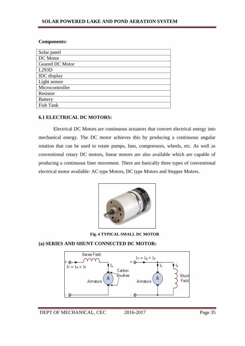
6.1 ELECTRICAL DC MOTORS:
Electrical DC Motors are continuous actuators that convert electrical energy into
mechanical energy. The DC motor achieves this by producing a continuous angular
rotation that can be used to rotate pumps, fans, compressors, wheels, etc. As well as
conventional rotary DC motors, linear motors are also available which are capable of
producing a continuous liner movement. There are basically three types of conventional
electrical motor available: AC type Motors, DC type Motors and Stepper Motors.
Fig. 4 TYPICAL SMALL DC MOTOR
(a) SERIES AND SHUNT CONNECTED DC MOTOR:
DEPT OF MECHANICAL, CEC 2016-2017 Page 36
SOLAR POWERED LAKE AND POND AERATION SYSTEM
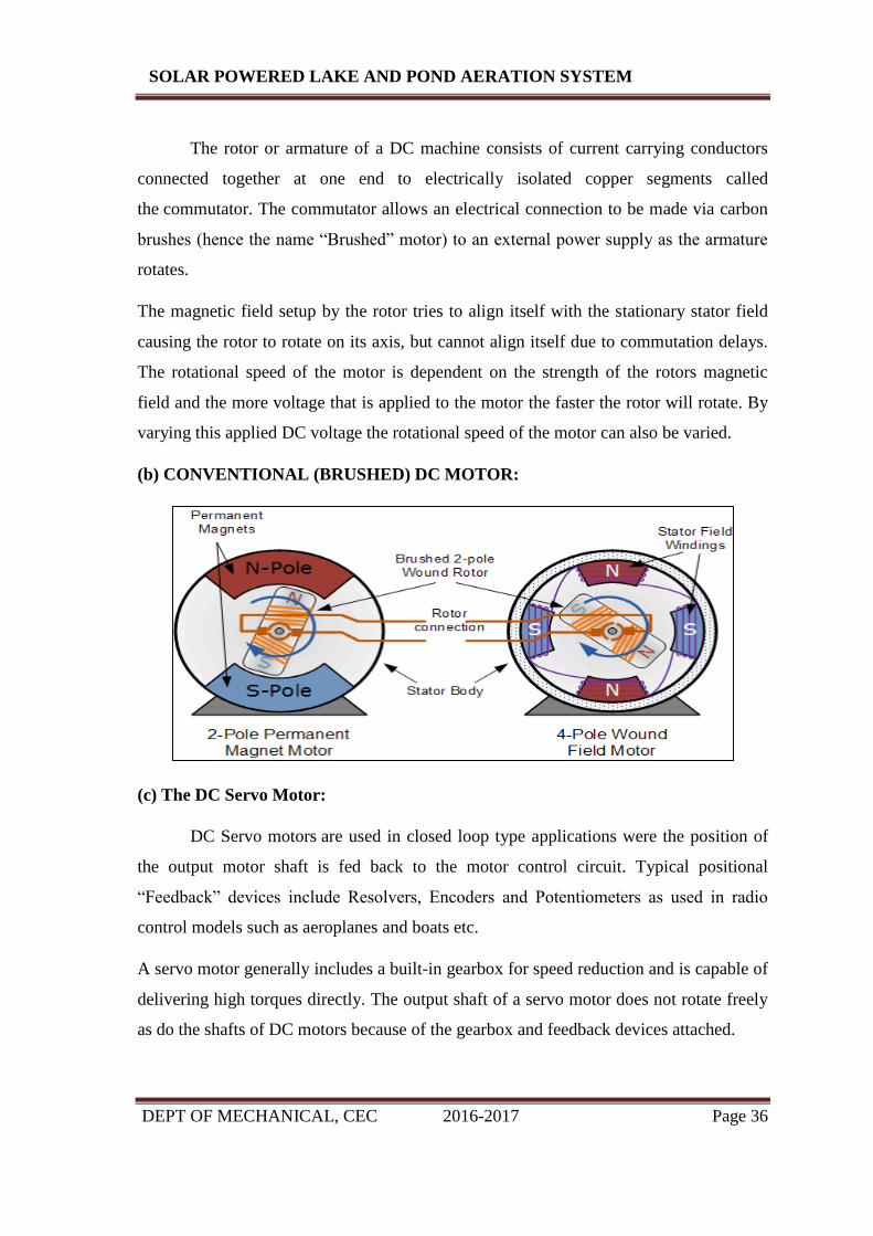
The rotor or armature of a DC machine consists of current carrying conductors
connected together at one end to electrically isolated copper segments called
the commutator. The commutator allows an electrical connection to be made via carbon
brushes (hence the name “Brushed” motor) to an external power supply as the armature
rotates.
The magnetic field setup by the rotor tries to align itself with the stationary stator field
causing the rotor to rotate on its axis, but cannot align itself due to commutation delays.
The rotational speed of the motor is dependent on the strength of the rotors magnetic
field and the more voltage that is applied to the motor the faster the rotor will rotate. By
varying this applied DC voltage the rotational speed of the motor can also be varied.
(b) CONVENTIONAL (BRUSHED) DC MOTOR:
(c) The DC Servo Motor:
DC Servo motors are used in closed loop type applications were the position of
the output motor shaft is fed back to the motor control circuit. Typical positional
“Feedback” devices include Resolvers, Encoders and Potentiometers as used in radio
control models such as aeroplanes and boats etc.
A servo motor generally includes a built-in gearbox for speed reduction and is capable of
delivering high torques directly. The output shaft of a servo motor does not rotate freely
as do the shafts of DC motors because of the gearbox and feedback devices attached.

DEPT OF MECHANICAL, CEC 2016-2017 Page 37
SOLAR POWERED LAKE AND POND AERATION SYSTEM
Fig.5 DC SERVO MOTOR
(d) MOTOR SPEED CONTROL:
The simple switching circuit above shows the circuit for a Uni-directional (one direction
only) motor speed control circuit. As the rotational speed of a DC motor is proportional
to the voltage across its terminals, we can regulate this terminal voltage using a
transistor. The two transistors are connected as a Darlington pair to control the main
armature current of the motor. A 5kΩ potentiometer is used to control the amount of base
drive to the first pilot transistorTR1, which in turn controls the main switching
transistor, TR2 allowing the motor’s DC voltage to be varied from zero to Vcc, in this
example 9 to 12 volts.
Optional flywheel diodes are connected across the switching transistor, TR2 and the
motor terminals for protection from any back emf generated by the motor as it rotates.
The adjustable potentiometer could be replaced with continuous logic “1” or logic “0”
signal applied directly to the input of the circuit to switch the motor “fully-ON”
(saturation) or “fully-OFF” (cut-off) respectively from the port of a micro-controller or
PIC. As well as this basic speed control, the same circuit can also be used to control the
motors rotational speed. By repeatedly switching the motor current “ON” and “OFF” at a
high enough frequency, the speed of the motor can be varied between stand still (0 rpm)
and full speed (100%) by varying the mark-space ratio of its supply. This is achieved by
DEPT OF MECHANICAL, CEC 2016-2017 Page 38
SOLAR POWERED LAKE AND POND AERATION SYSTEM
varying the proportion of “ON” time (tON) to the “OFF” time (tOFF) and this can be
achieved using a process known as Pulse Width Modulation.
6.2 FISH TANK:
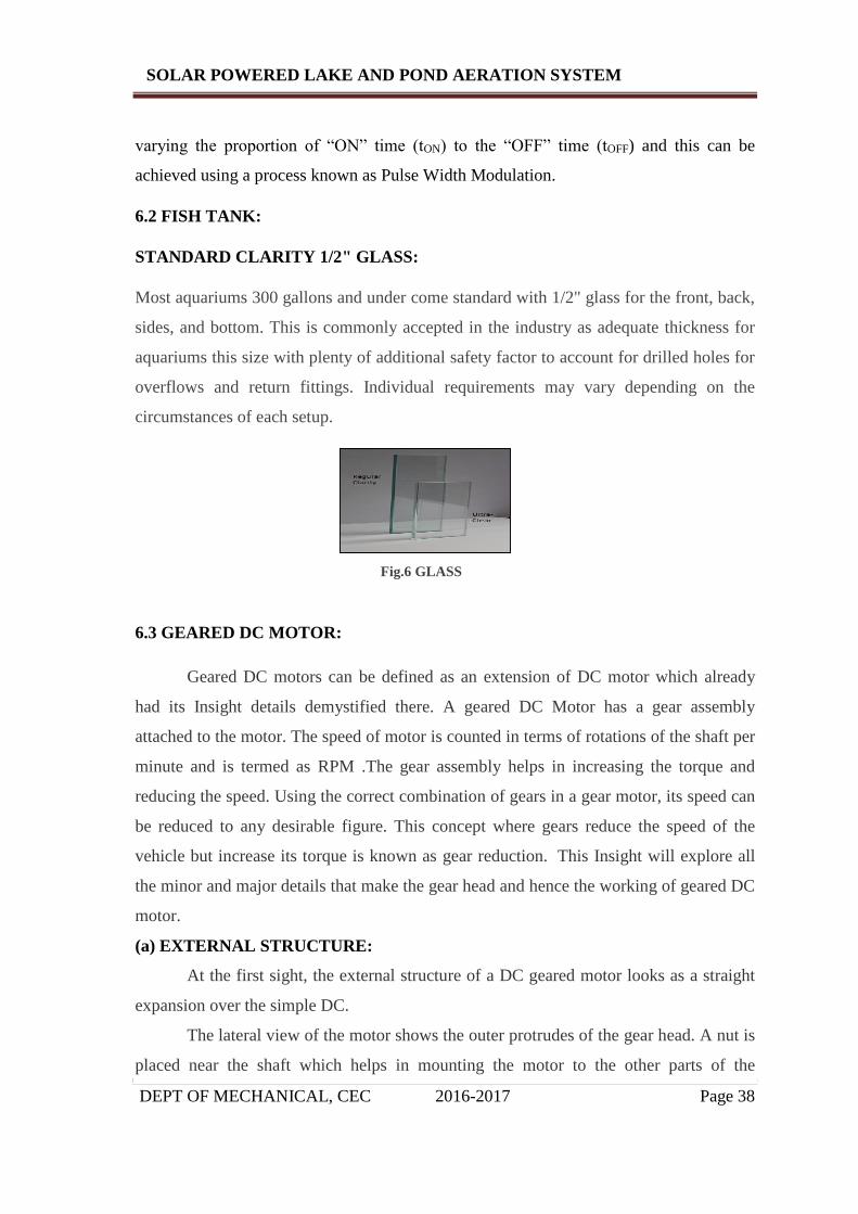
STANDARD CLARITY 1/2" GLASS:
Most aquariums 300 gallons and under come standard with 1/2" glass for the front, back,
sides, and bottom. This is commonly accepted in the industry as adequate thickness for
aquariums this size with plenty of additional safety factor to account for drilled holes for
overflows and return fittings. Individual requirements may vary depending on the
circumstances of each setup.
Fig.6 GLASS
6.3 GEARED DC MOTOR:
Geared DC motors can be defined as an extension of DC motor which already
had its Insight details demystified there. A geared DC Motor has a gear assembly
attached to the motor. The speed of motor is counted in terms of rotations of the shaft per
minute and is termed as RPM .The gear assembly helps in increasing the torque and
reducing the speed. Using the correct combination of gears in a gear motor, its speed can
be reduced to any desirable figure. This concept where gears reduce the speed of the
vehicle but increase its torque is known as gear reduction. This Insight will explore all
the minor and major details that make the gear head and hence the working of geared DC
motor.
(a) EXTERNAL STRUCTURE:
At the first sight, the external structure of a DC geared motor looks as a straight
expansion over the simple DC.
The lateral view of the motor shows the outer protrudes of the gear head. A nut is
placed near the shaft which helps in mounting the motor to the other parts of the
DEPT OF MECHANICAL, CEC 2016-2017 Page 39
SOLAR POWERED LAKE AND POND AERATION SYSTEM
assembly. Also, an internally threaded hole is there on the shaft to allow attachments or
extensions such as wheel to be attached to the motor.
The outer body of the gear head is made of high density plastic but it is quite easy
to open as only screws are used to attach the outer and the inner structure. The major
reason behind this could be to lubricate gear head from time to time. The plastic body
has a threading through which nut can be easily mounted and vice versa from the gear
head.
Fig.7.1 EXTERNAL STRUCTURE
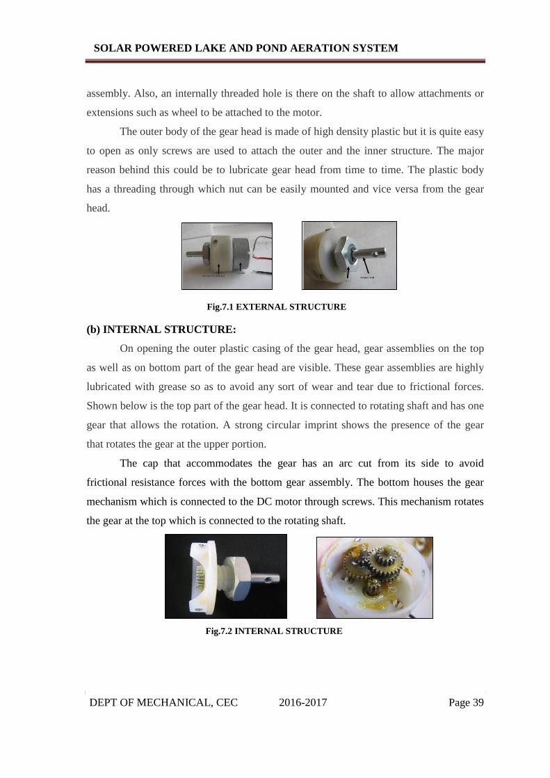
(b) INTERNAL STRUCTURE:
On opening the outer plastic casing of the gear head, gear assemblies on the top
as well as on bottom part of the gear head are visible. These gear assemblies are highly
lubricated with grease so as to avoid any sort of wear and tear due to frictional forces.
Shown below is the top part of the gear head. It is connected to rotating shaft and has one
gear that allows the rotation. A strong circular imprint shows the presence of the gear
that rotates the gear at the upper portion.
The cap that accommodates the gear has an arc cut from its side to avoid
frictional resistance forces with the bottom gear assembly. The bottom houses the gear
mechanism which is connected to the DC motor through screws. This mechanism rotates
the gear at the top which is connected to the rotating shaft.
Fig.7.2 INTERNAL STRUCTURE

DEPT OF MECHANICAL, CEC 2016-2017 Page 40
SOLAR POWERED LAKE AND POND AERATION SYSTEM
(d) WORKING OF GEARED DC MOTOR:
The DC motor works over a fair range of voltage. The higher the input voltage
more is the RPM (rotations per minute) of the motor. For example, if the motor works in
the range of 6-12V, it will have the least RPM at 6V and maximum at 12 V.
In terms of voltage, we can put the equation as:
RPM= K1 * V, where,
K1= induced voltage constant
V=voltage applied
The working of the gears is very interesting to know. It can be explained by the
principle of conservation of angular momentum. The gear having smaller radius will
cover more RPM than the one with larger radius. However, the larger gear will give
more torque to the smaller gear than vice versa. The comparison of angular velocity
between input gear (the one that transfers energy) to output gear gives the gear ratio.
When multiple gears are connected together, conservation of energy is also followed.
The direction in which the other gear rotates is always the opposite of the gear adjacent
to it.
In any DC motor, RPM and torque are inversely proportional. Hence the gear
having more torque will provide a lesser RPM and converse. In a geared DC motor, the
concept of pulse width modulation is applied.
In a geared DC motor, the gear connecting the motor and the gear head is quite
small, hence it transfers more speed to the larger teeth part of the gear head and makes it
rotate. The larger part of the gear further turns the smaller duplex part. The small duplex
part receives the torque but not the speed from its predecessor which it transfers to larger
part of other gear and so on. The third gear’s duplex part has more teeth than others and
hence it transfers more torque to the gear that is connected to the shaft.
6.4 L293D –DC MOTOR DRIVER IC:
We start with the L293D. L293D is a popular motor driving IC. It is a 16 pin
IC. The IC has 8 pins on both the sides. It has 2 enable pins, 1 VSS pin, 1 VS pin, 4
ground pins, 4 input pins and 4 output pins. Though not required here, but in case you
wish to learn how to interface L293D with a microcontroller.

DEPT OF MECHANICAL, CEC 2016-2017 Page 41
SOLAR POWERED LAKE AND POND AERATION SYSTEM
Fig.8.1 L293D Pin Configuration
(a) PIN DESCRIPTIONS:
Enable – the enable pins, when are given true, (i.e. 1) then they enable the respective
part of the IC. The enable 1 chip enables the Left part of the IC for inputs and outputs,
and so does the Enable 2 does to the right part of the IC.
1. VSS – this pin is to be given an input of 5 volts. This is used to power up the chip
for its operations.
2. VS – This pin is given the voltage that we have to supply to the motors. This
voltage comes out through the output pins. Due to the gates used in the IC, the output
is usually 1.8 to 2 volts less than the Vs.
3. Input – the input pin decides whether output has to be given to the respective
output pin or not. When the Input is true, then output is also 1in the respective output
pin. When input in the Input pin is 0, and then output in the respective output pin is
also 0.
4. Output – the output pin is connected to the terminals of the motor. The input pins,
as stated above, control its output.
5. GND – these pins are the ground pins, or, in other words, Zero.
The L293D IC can be used to control a maximum of 4 motors simultaneously.
When 4 motors are connected to the IC, then for operation, -ve of each of the motors is
connected to the GND, and the +ve terminal to the outputs. For bidirectional control,
you can connect only two motors simultaneously as per the circuit diagram below:

DEPT OF MECHANICAL, CEC 2016-2017 Page 42
SOLAR POWERED LAKE AND POND AERATION SYSTEM
Fig.8.2 L293D BASED MOTOR DRIVER
6.5 LIQUID CRYSTAL DISPLAY:
A liquid crystal display (LCD) is a flat panel display, electronic visual display, or video
display that uses the light modulating properties of liquid crystals. Liquid crystals do not emit
light directly. LCDs are available to display arbitrary images (as in a general-purpose computer
display) or fixed images which can be displayed or hidden, such as preset words, digits, and 7-
segment displays as in a digital clock. They use the same basic technology, except that arbitrary
images are made up of a large number of small pixels, while other displays have larger elements.
An LCD is a small low cost display. It is easy to interface with a micro-controller because of an
embedded controller (the black blob on the back of the board). This controller is standard across
many displays (HD 44780) which means many micro-controllers (including the Arduino) have
libraries that make displaying messages as easy as a single line of code.
Fig.9.1 LCD DISPLAY UNIT
LCDs are used in a wide range of applications including computer
monitors, televisions, instrument panels, aircraft cockpit displays, and signage. They are common

DEPT OF MECHANICAL, CEC 2016-2017 Page 43
SOLAR POWERED LAKE AND POND AERATION SYSTEM
in consumer devices such as video players, gaming devices, clocks, watches, calculators,
and telephones, and have replaced cathode ray tube (CRT) displays in most applications. They
are available in a wider range of screen sizes than CRT and plasma displays, and since they do
not use phosphors, they do not suffer image burn-in. LCDs are, however, susceptible to image
persistence.
Fig.9.2 INTRENAL WORKING OF LCD UNIT
Pin
No Function Name
1 Ground (0V) Ground
2 Supply voltage; 5V (4.7V – 5.3V) Vcc
3 Contrast adjustment; through a variable resistor VEE
4 Selects command register when low; and data register when
high Register Select
5 Low to write to the register; High to read from the register Read/write
6 Sends data to data pins when a high to low pulse is given Enable
7
8-bit data pins
DB0
8 DB1
9 DB2
10 DB3
11 DB4
12 DB5
13 DB6
14 DB7
15 Backlight VCC (5V) Led+
16 Backlight Ground (0V) Led-

DEPT OF MECHANICAL, CEC 2016-2017 Page 44
SOLAR POWERED LAKE AND POND AERATION SYSTEM
6.6 LIGHT SENSORS:
A Light Sensor generates an output signal indicating the intensity of light by
measuring the radiant energy that exists in a very narrow range of frequencies basically
called “light”, and which ranges in frequency from “Infra-red” to “Visible” up to
“Ultraviolet” light spectrum. The Light Sensor is a passive devices that convert this
“light energy” whether visible or in the infra-red parts of the spectrum into an electrical
signal output. Light sensors are more commonly known as “Photoelectric Devices” or
“Photo Sensors” because the convert light energy (photons) into electricity (electrons).
(a) THE PHOTOCONDUCTIVE CELL:
A Photoconductive light sensor does not produce electricity but simply changes
its physical properties when subjected to light energy. The most common type of
photoconductive device is the Photo resistor which changes its electrical resistance in
response to changes in the light intensity. Photo resistors are Semiconductor devices that
use light energy to control the flow of electrons, and hence the current flowing through
them. The commonly used Photoconductive Cell is called the Light Dependent
Resistor or LDR.
(b) THE LIGHT DEPENDENT RESISTOR:
Fig.10.1 TYPICAL LDR
As its name implies, the Light Dependent Resistor (LDR) is made from a piece of
exposed semiconductor material such as cadmium sulphide that changes its electrical

DEPT OF MECHANICAL, CEC 2016-2017 Page 45
SOLAR POWERED LAKE AND POND AERATION SYSTEM
resistance from several thousand Ohms in the dark to only a few hundred Ohms when
light falls upon it by creating hole-electron pairs in the material.
Materials used as the semiconductor substrate include, lead sulphide (PbS), lead
selenide (PbSe), indium anti monide (InSb) which detect light in the infra-red range with
the most commonly used of all photo resistive light sensors being Cadmium
Sulphide (Cds).
Cadmium sulphide is used in the manufacture of photoconductive cells because
its spectral response curve closely matches that of the human eye and can even be
controlled using a simple torch as a light source. Typically then, it has a peak sensitivity
wavelength (λp) of about 560nm to 600nm in the visible spectral range.
(c) THE LIGHT DEPENDENT RESISTOR CELL:
Fig.10.2 THE LIGHT DEPENDENT RESISTOR CELL
The most commonly used photo resistive light sensor is the ORP12 Cadmium
Sulphide photoconductive cell. This light dependent resistor has a spectral response of
about 610nm in the yellow to orange region of light. The resistance of the cell when UN
illuminated (dark resistance) is very high at about 10MΩ’s which falls to about 100Ω’s
when fully illuminated (lit resistance).
To increase the dark resistance and therefore reduce the dark current, the resistive path
forms a zigzag pattern across the ceramic substrate. The CdS photocell is a very low cost
device often used in auto dimming, darkness or twilight detection for turning the street
lights “ON” and “OFF”, and for photographic exposure meter type applications.

DEPT OF MECHANICAL, CEC 2016-2017 Page 46
SOLAR POWERED LAKE AND POND AERATION SYSTEM
(d) LDR SWITCH:
This basic light sensor circuit is of a relay output light activated switch. A
potential divider circuit is formed between the photo resistor, LDR and the resistor R1.
When no light is present i.e. in darkness, the resistance of the LDR is very high in the
Mega ohms (MΩ’s) range so zero base bias is applied to the transistor TR1 and the relay
is de-energized or “OFF”.
As the light level increases the resistance of the LDR starts to decrease causing the base
bias voltage at V1 to rise. At some point determined by the potential divider network
formed with resistor R1, the base bias voltage is high enough to turn the
transistor TR1 “ON” and thus activate the relay which in turn is used to control some
external circuitry. As the light level falls back to darkness again the resistance of
the LDR increases causing the base voltage of the transistor to decrease, turning the
transistor and relay “OFF” at a fixed light level determined again by the potential divider
network. By replacing the fixed resistor R1 with a potentiometer VR1, the point at which
the relay turns “ON” or “OFF” can be pre-set to a particular light level. This type of
simple circuit shown above has a fairly low sensitivity and its switching point may not be
consistent due to variations in either temperature or the supply voltage. A more sensitive
precision light activated circuit can be easily made by incorporating the LDR into a
“Wheatstone Bridge” arrangement and replacing the transistor with an Operational
Amplifier as shown.
Fig.11 LIGHT LEVEL SENSING CIRCUIT

DEPT OF MECHANICAL, CEC 2016-2017 Page 47
SOLAR POWERED LAKE AND POND AERATION SYSTEM
(e) PHOTO-DIODE AMPLIFIER CIRCUIT:
Photodiodes are very versatile light sensors that can turn its current flow both
“ON” and “OFF” in nanoseconds and are commonly used in cameras, light meters, CD
and DVD-ROM drives, TV remote controls, scanners, fax machines and copiers etc, and
when integrated into operational amplifier circuits as infrared spectrum detectors for
fibre optic communications, burglar alarm motion detection circuits and numerous
imaging, laser scanning and positioning systems etc.
Fig.12 PHOTO-DIODE CIRCUIT
(f) PHOTOVOLTAIC CELLS:
The most common type of photovoltaic light sensor is the Solar Cell. Solar cells
convert light energy directly into DC electrical energy in the form of a voltage or current
to a power a resistive load such as a light, battery or motor. Then photovoltaic cells are
similar in many ways to a battery because they supply DC power.
Solar cells are used in many different types of applications to offer an alternative
power source from conventional batteries, such as in calculators, satellites and now in
homes offering a form of renewable power.
Fig.13 PHOTOVOLTIC CELL

DEPT OF MECHANICAL, CEC 2016-2017 Page 48
SOLAR POWERED LAKE AND POND AERATION SYSTEM
Photovoltaic cells are made from single crystal silicon PN junctions, the same as
photodiodes with a very large light sensitive region but are used without the reverse bias.
They have the same characteristics as a very large photodiode when in the dark.
When illuminated the light energy causes electrons to flow through the PN junction and
an individual solar cell can generate an open circuit voltage of about 0.58v (580mV).
Solar cells have a “Positive” and a “Negative” side just like a battery.
Individual solar cells can be connected together in series to form solar panels which
increases the output voltage or connected together in parallel to increase the available
current. Commercially available solar panels are rated in Watts, which is the product of
the output voltage and current (Volts times Amps) when fully lit.
(g) CHARACTERISTICS OF A TYPICAL PHOTOVOLTIC SOLAR CELL:
Fig.14 PHOTOVOLTIC SOLAR CELL
The amount of available current from a solar cell depends upon the light intensity, the
size of the cell and its efficiency which is generally very low at around 15 to 20%. To
increase the overall efficiency of the cell commercially available solar cells use
polycrystalline silicon or amorphous silicon, which have no crystalline structure, and can
generate currents of between 20 to 40mA per cm2.

DEPT OF MECHANICAL, CEC 2016-2017 Page 49
SOLAR POWERED LAKE AND POND AERATION SYSTEM
CHAPTER 7
HARDWARE REQUIREMENT
DEPT OF MECHANICAL, CEC 2016-2017 Page 50
SOLAR POWERED LAKE AND POND AERATION SYSTEM
7.1 PIC MICROCONTROLLER
Introduction:
Peripheral Interface Controllers (PIC) is one of the advanced microcontrollers
developed by microchip technologies. These microcontrollers are widely used in modern
electronics applications. A PIC controller integrates all type of advanced interfacing
ports and memory modules. These controllers are more advanced than normal
microcontroller like INTEL 8051. The first PIC chip was announced in 1975 (PIC1650).
As like normal microcontroller, the PIC chip also combines a microprocessor unit
called CPU and is integrated with various types of memory modules (RAM, ROM,
EEPROM, etc), I/O ports, timers/counters, communication ports, etc.
All PIC microcontroller family uses Harvard architecture. This architecture has
the program and data accessed from separate memories so the device has a program
memory bus and a data memory bus (more than 8 lines in a normal bus). This improves
the bandwidth (data throughput) over traditional von Neumann architecture where
program and data are fetched from the same memory (accesses over the same bus).
Separating program and data memory further allows instructions to be sized differently
than the 8-bit wide data word.
(a) PIC DEVELOPMENT BOARD:
The PIC development board is the important circuit element in the project. Its
previous predecessor was the PIC DEM2 board which has its faults. The central pin
element is the 40 pin socket to the programmed PIC chip into; a ZIF socket has also been
placed in to it. The board was designed to be powered by a DC supply. This voltage was
then passed through a voltage regulator on the board which reduces the voltage to 5 VDC
required for the controller.
The current rating to the wall adapter is 300mA which was more than sufficient
to run the board and peripherals. The next major element in it is the Oscillator. It has a
PIC DEM2 board (a Microchip) which uses 12MHz that was carried through for use in
the development board. It has 14 pin footprints but only the corner 4 pins are utilized for
the circuit. The remaining portion of the board consists of the I\0 pins that are connected
to various small strips throughout the board and are ready for the connection.

DEPT OF MECHANICAL, CEC 2016-2017 Page 51
SOLAR POWERED LAKE AND POND AERATION SYSTEM
Fig.15 PIC MICROCONTROLLER
(b) PROGRAMMING THE PIC MICROCONTROLLER:
The main benefit of the 16f877 for our application was the flash program
memory which was used for the easy reprogramming ability. The chip, that you flash the
memory with the assembled machine language using a programmer of your choice. The
programmer was that available to us at the time was the PIC star plus programmer which
works flawlessly. The programming was done in the C programming language and was
compiled and assembled in to the microcontroller’s machine language.
This offers the benefit of readability and portability. A tip presented to us by our
instructor when programming the microcontroller is to disable as many features which
offer no use in our application. This removes any unwanted behaviour which may be a
result of these features and could be later enabled if it offers any benefit after
development.
7.2 POWER SUPPLY CIRCUIT:
Power supply is a reference to a source of electrical power. A device or system
that supplies electrical or other types of energy to an output load or group of loads is
called a power supply unit or PSU. The term is most commonly applied to electrical
energy supplies, less often to mechanical ones, and rarely to others.
Power supplies for electronic devices can be broadly divided into linear and
switching power supplies. The linear supply is a relatively simple design that becomes
increasingly bulky and heavy for high current devices; voltage regulation in a linear
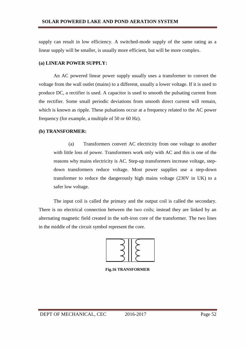
DEPT OF MECHANICAL, CEC 2016-2017 Page 52
SOLAR POWERED LAKE AND POND AERATION SYSTEM
supply can result in low efficiency. A switched-mode supply of the same rating as a
linear supply will be smaller, is usually more efficient, but will be more complex.
(a) LINEAR POWER SUPPLY:
An AC powered linear power supply usually uses a transformer to convert the
voltage from the wall outlet (mains) to a different, usually a lower voltage. If it is used to
produce DC, a rectifier is used. A capacitor is used to smooth the pulsating current from
the rectifier. Some small periodic deviations from smooth direct current will remain,
which is known as ripple. These pulsations occur at a frequency related to the AC power
frequency (for example, a multiple of 50 or 60 Hz).
(b) TRANSFORMER:
(a) Transformers convert AC electricity from one voltage to another
with little loss of power. Transformers work only with AC and this is one of the
reasons why mains electricity is AC. Step-up transformers increase voltage, step-
down transformers reduce voltage. Most power supplies use a step-down
transformer to reduce the dangerously high mains voltage (230V in UK) to a
safer low voltage.
The input coil is called the primary and the output coil is called the secondary.
There is no electrical connection between the two coils; instead they are linked by an
alternating magnetic field created in the soft-iron core of the transformer. The two lines
in the middle of the circuit symbol represent the core.
Fig.16 TRANSFORMER

DEPT OF MECHANICAL, CEC 2016-2017 Page 53
SOLAR POWERED LAKE AND POND AERATION SYSTEM
(b) Transformers waste very little power so the power out is (almost)
equal to the power in. Note that as voltage is stepped down current is stepped up.
The ratio of the number of turns on each coil, called the turn’s ratio, determines the ratio
of the voltages. A step-down transformer has a large number of turns on its primary
(input) coil which is connected to the high voltage mains supply, and a small number of
turns on its secondary (output) coil to give a low output voltage.
Fig.17.1 POWER SUPPLY CIRCUIT
Fig.17.2 POWER SUPPLY CIRCUIT ALONG RESISTOR
7.3 RESISTORS:
Resistors, (R) are the most fundamental and commonly used of all the electronic
components, to the point where they are almost taken for granted. There are many
different Types of Resistor available for the electronics constructor to choose from,
from very small surface mount chip resistors up to large wire wound power resistors.

DEPT OF MECHANICAL, CEC 2016-2017 Page 54
SOLAR POWERED LAKE AND POND AERATION SYSTEM
The principal job of a resistor within an electrical or electronic circuit is to “resist”
(hence the name Resistor), regulate or to set the flow of electrons (current) through them
by using the type of conductive material from which they are composed.
TYPES OF RESISTORS:
(a) CARBON RESISTOR
Fig.18.1
The Carbon Composite Resistor is a low to medium type power resistor which has a low
inductance making them ideal for high frequency applications but they can also suffer
from noise and stability when hot. Carbon composite resistors are generally prefixed
with a “CR” notation (CR10kΩ) and are available in E6 (± 20% tolerance)
(accuracy), E12 (± 10% tolerance) and E24 (5% tolerance) packages with power ratings
from 0.125 or 1/4 of a Watt up to 5 Watts.
Carbon composite resistor types are very cheap to make and are therefore commonly
used in electrical circuits. However, due to their manufacturing process carbon type
resistors have very large tolerances so for more precision and high value resistances, film
type resistors are used instead.

DEPT OF MECHANICAL, CEC 2016-2017 Page 55
SOLAR POWERED LAKE AND POND AERATION SYSTEM
(b) FILM RESISTOR
Fig.18.2
Metal Film Resistors have much better temperature stability than their carbon
equivalents, lower noise and are generally better for high frequency or radio frequency
applications. Metal Oxide Resistors have better high surge current capability with a
much higher temperature rating than the equivalent metal film resistors.
Another type of film resistor commonly known as a Thick Film Resistor is manufactured
by depositing a much thicker conductive paste of Ceramic and Metal, called Cermet,
onto an alumina ceramic substrate. Cermet resistors have similar properties to metal film
resistors and are generally used for making small surface mount chip type resistors,
multi-resistor networks in one package for pcb’s and high frequency resistors. They have
good temperature stability, low noise, and good voltage ratings but low surge current
properties.
Metal Film Resistors are prefixed with a “MFR” notation (eg, MFR100kΩ) and a CF for
Carbon Film types. Metal film resistors are available in E24 (±5% & ±2%
tolerances), E96 (±1%tolerance) and E192 (±0.5%, ±0.25% & ±0.1% tolerances)
packages with power ratings of 0.05 (1/20th) of a Watt up to 1/2 Watt. Generally
speaking Film resistors are precision low power components.

DEPT OF MECHANICAL, CEC 2016-2017 Page 56
SOLAR POWERED LAKE AND POND AERATION SYSTEM
(c) WIRE WOUND RESISTOR
Fig.18.3
Wire wound resistor types are prefixed with a “WH” or “W” notation (eg WH10Ω) and
are available in the WH aluminium clad package (±1%, ±2%, ±5% & ±10% tolerance) or
the W vitreous enamelled package (±1%, ±2% & ±5% tolerance) with power ratings
from 1W to 300W or more.
Another type of wire wound resistor is the Power Wire wound Resistor. These are high
temperature, high power non-inductive resistor types generally coated with a vitreous or
glass epoxy enamel for use in resistance banks or DC motor/servo control and dynamic
braking applications. They can even be used as low wattage space or cabinet heaters.
The non-inductive resistance wire is wound around a ceramic or porcelain tube covered
with mica to prevent the alloy wires from moving when hot. Wire wound resistors are
available in a variety of resistance and power ratings with one main use of power wire
wound resistor is in the electrical heating elements of an electric fire which converts the
electrical current flowing through it into heat with each element dissipating up to 1000
Watts, (1kW) of energy.
7.4 SOLAR PANEL:
Solar panels absorb the sunlight as a source of energy to generate electricity or heat.
A photovoltaic system, also solar PV power system, or PV system, is a power system designed to
supply usable solar power by means of photovoltaics. It consists of an arrangement of several
components, including solar panels to absorb and convert sunlight into electricity, a solar
inverter to change the electric current from DC to AC, as well as mounting, cabling and other
electrical accessories to set up a working system. It may also use a solar tracking system to
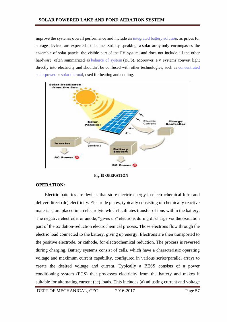
DEPT OF MECHANICAL, CEC 2016-2017 Page 57
SOLAR POWERED LAKE AND POND AERATION SYSTEM
improve the system's overall performance and include an integrated battery solution, as prices for
storage devices are expected to decline. Strictly speaking, a solar array only encompasses the
ensemble of solar panels, the visible part of the PV system, and does not include all the other
hardware, often summarized as balance of system (BOS). Moreover, PV systems convert light
directly into electricity and shouldn't be confused with other technologies, such as concentrated
solar power or solar thermal, used for heating and cooling.
Fig.19 OPERATION
OPERATION:
Electric batteries are devices that store electric energy in electrochemical form and
deliver direct (dc) electricity. Electrode plates, typically consisting of chemically reactive
materials, are placed in an electrolyte which facilitates transfer of ions within the battery.
The negative electrode, or anode, “gives up” electrons during discharge via the oxidation
part of the oxidation-reduction electrochemical process. Those electrons flow through the
electric load connected to the battery, giving up energy. Electrons are then transported to
the positive electrode, or cathode, for electrochemical reduction. The process is reversed
during charging. Battery systems consist of cells, which have a characteristic operating
voltage and maximum current capability, configured in various series/parallel arrays to
create the desired voltage and current. Typically a BESS consists of a power
conditioning system (PCS) that processes electricity from the battery and makes it
suitable for alternating current (ac) loads. This includes (a) adjusting current and voltage

DEPT OF MECHANICAL, CEC 2016-2017 Page 58
SOLAR POWERED LAKE AND POND AERATION SYSTEM
to maximize power output, (b) converting DC power to AC power, (c) matching the
converted AC electricity to a utility’s AC electrical network, and (d) halting current flow
from the system into the grid during utility outages to safeguard utility personnel. The
conversion from DC to AC power in the PCS is achieved by an inverter, which is a set of
electronic switches that change DC voltage from battery to AC voltage in order to serve
an AC load.
7.5.1 LEAD-ACID BATTERY:
Lead acid batteries are marginally economic but they have substantial space and
maintenance requirements. They also have a shorter life, which decreases rapidly if
battery is discharged below 30%. This results in the reduction of energy density
amounting to increased capital costs. They are commonly installed in uninterruptible
power supply (UPS) systems as well as in renewable and distributed power systems. The
largest one installed is a 40 MWh system in Chino, California.
7.5.2 VALVE REGULATED LEAD ACID BATTERY (VRLA):
VRLAs use the same basic electrochemical technology as flooded lead-acid
batteries, but these batteries are closed with a pressure regulating valve, so that they are
essentially sealed. In addition, the acid electrolyte is immobilized. This eliminates the
need to add water to the cells to keep the electrolyte functioning properly, or to mix the
electrolyte to prevent stratification. The oxygen recombination and the valves of VRLAs
prevent the venting of hydrogen and oxygen gases and the ingress of air into the cells.
The battery subsystem may need to be replaced more frequently than with the flooded
lead-acid battery, increasing the levelized cost of the system. The major advantages of
VRLAs over flooded lead-acid cells are: a) the dramatic reduction in the maintenance
that is necessary to keep the battery in operation, and b) the battery cells can be packaged
more tightly because of the sealed construction and immobilized electrolyte, reducing the
footprint and weight of the battery. The disadvantages of VRLAs are that they are less
robust than flooded lead-acid batteries, and they are more costly and shorter-lived.
VRLAs are perceived as being maintenance free and safe and have become popular for
standby power supplies in telecommunications applications and for uninterruptible
power supplies in situations where special rooms cannot be set aside for the batteries.

DEPT OF MECHANICAL, CEC 2016-2017 Page 59
SOLAR POWERED LAKE AND POND AERATION SYSTEM
Fig.20 VRLA BATTERY
7.6 WATER PUMP MOTOR:
The pumping of water is a basic and practical technique, far more practical than
scooping it up with one's hands or lifting it in a hand-held bucket. This is true whether
the water is drawn from a fresh source, moved to a needed location, purified, or used for
irrigation, washing, or sewage treatment, or for evacuating water from an undesirable
location. Regardless of the outcome, the energy required to pump water is an extremely
demanding component of water consumption. All other processes depend or benefit
either from water descending from a higher elevation or some pressurized plumbing
system.
The ancient concept of the aqueduct took simple and eloquent advantage of
maintaining elevation of water for as long and far a distance as possible. Thus, as water
moves over great distances, it retains a larger component of its potential energy by
spending small portions of this energy flowing down a slight gradation. Granted, a useful
aqueduct system ultimately depends on a fresh water source existing at a higher elevation
than the location.
Fig.21 WATER PUMP MOTOR

DEPT OF MECHANICAL, CEC 2016-2017 Page 60
SOLAR POWERED LAKE AND POND AERATION SYSTEM
Fig.22 BLOCK DIAGRAM OF SOLAR POWERED LAKE AND POND AERATION SYSTEM

DEPT OF MECHANICAL, CEC 2016-2017 Page 61
SOLAR POWERED LAKE AND POND AERATION SYSTEM
TOTAL EXPECTED BUDGET: 38,000/-
COMPONENTS QUANTITY COST
Solar panel(s) 2 4000
Deep cycle gel cell solar batteries 2 2500
Brushless DC compressor 1 1200
Wiring harness kit 1 1700
Pro star charge control centre 1 900
12/24 volt smart box converter 1 2000
Programmable digital timer 1 600
Energy efficient, high volume air
compressors
1 4000
100% recycled plastic cabinet equipped with
cooling and sound reduction packages
1 1500
Fully-adjustable manifold with safety relief
valve and pressure gauge
1 1500
Duraplate self-cleaning, non-clogging,
membrane diffusers
2 4500
Complete fittings package 1 2000
Oxygen/Ozone Generation systems 1 2000
Automatic Solar Tracking System 1 3500
Acrylic Flowmeters 1 2200
Alpine Self-weighted Feeder Tubing 1 3400
Installation and maintenance 2500
DEPT OF MECHANICAL, CEC 2016-2017 Page 62
SOLAR POWERED LAKE AND POND AERATION SYSTEM
ADVANTAGES:
Improves the aesthetics and overall health of ponds and lakes.
Targets the "cause" of the problem, rather than just its "symptoms".
Eliminates the need for harmful chemicals.
Reduces maintenance, saving your money and time.
Improves Water Quality and Clarity.
Improves Fish and Water fowl habitat.
APPLICATIONS:
For aquatic environments ranging in size from small ornamental ponds to lakes
up for filtration.
Remote areas installation
Environmentally beneficial landscaping / aqua scaping.

DEPT OF MECHANICAL, CEC 2016-2017 Page 63
SOLAR POWERED LAKE AND POND AERATION SYSTEM
CONCLUSION
We are proud that we have completed the work within the limited time
successfully. At the end of this project you will have more inside knowledge about
SOLAR POWERED LAKE AND POND AERATION SYSTEM. Our project is
interesting as well has a detailed evaluation of prevailiry chemical and biological
limnology and anticipated effects and engineering evaluation of most appropriate
technology was utilized.
We have developed a project “SOLAR POWERED LAKE AND POND
AERATION SYSTEM” which helped in increasing dissolved oxygen by eliminating
stratified water and more information regarding aeration and filtration of lakes and
reservoirs is known.

DEPT OF MECHANICAL, CEC 2016-2017 Page 64
SOLAR POWERED LAKE AND POND AERATION SYSTEM
BIBLIOGRAPHY
INTERNET SOURCES:
1. Http://www.solardirect.com/pv/systems/systems.html
2. Http://www.energy.gov/energysources/solar.html
3. http://radiantsolar.com/info_library.php
4. http://www.quasarelectronics.com/microcontroller_projects.html
5. http://www.lib.ku.ac.th/KUCONF/KC4511046.pdf
6. http://www.clinictech.most.go.th/online/techlist/attatchFile/20111171720461.pdf
7. http://scienceanalys.com
TEXTBOOK:
1. Hefei zhang, Shabou huo, "A Hybrid Solar Desalination Process of the multi effect
Humidification Dehumidification and Basin type Unit" Desalination Vol.220 (2008)
Pages 552-557
2. Mayuresh Kathe, Akshay Acholkar, Nimish kavishwar, Mayur patil and Deepak
Devasagayam, "Solar Water Purifier" International Journal of Engineering Technology
Science and Research, Vol 2, Issue 4, April 2015.
3. J. Rizk and Y. Chaiko "Solar tracking System: More efficient use of Solar panels" in
Proc. World Academy of Science, Engineering and Technology, 2008, pp.2-3
4. Gay, CF and Wilson, JH and Yerkes, JW "Performance advantages of two-axis
tracking for large flat plate solar radiant systems" in Conf. Rec. IEEE Photovoltaic spec,
1982.
5. Microcontroller and Embedded Systems, By Dr.Rajiv Kapadia
6. Wilma Hurst, Tim. "Designing Embedded Systems with PIC Microcontrollers,
Elsevier, 2007, pp.137
7. Condit and Jones D.W, "Stepping Motor Fundamentals", Microchip.inc, 2004.
8. Daro UV systems LTD. "UV general information" about Underwatertreatment.co.uk-
water treatment applications, Daro UV systems, 2010, April 2014
9. Gregory, J Cryptosporidium "Water Treatment and Monitoring methods (Filtration
and Separation)
10. Stodard L, J Abiecunas, R O'Connell Economic, “Energy and Environmental Benifits
of Concentrating Solar Power". 2006