Embed Size (px)
Citation preview
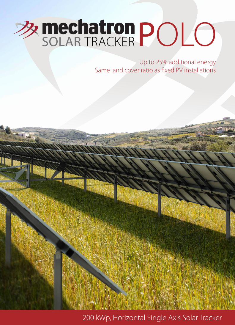
200 kWp, Horizontal Single Axis Solar Tracker
POLOSOLAR TRACKERUp to 25% additional energy
Same land cover ratio as fixed PV installations

Cost Effective InvestmentAlthough the cost of POLO Solar Tracker is slightly higher when compared to an equal capacity fixed installation, the increase
in energy production is significantly higher than the increase in the investment capital, therefore the IRR and the NPV of the
investment is greatly improved.
Lean Design
General Dimensioning
The POLO Solar Tracker’s lean design is based on Mechatron’s accumulated design
knowledge and field experience. Every detail has been thoroughly engineered to have
the minimum impact to LCOE.
The motion mechanism can drive up to 8 rows, 53 m long and 3 m wide each (25 kW).
The position of the pivot joints and the motion mechanism is out of reach of the modules
during the operation, therefore there are no gaps above the foundation, making POLO
Solar Tracker the solution with the best Ground Coverage Ratio.
The structure is a combination of large diameter rectangle tubes and cantilever purlins
providing maximum material usage efficiency and enabling great cost reductions.
In order to secure safe operation for many years the POLO Solar Tracker uses a hydraulic
motion mechanism. The motion mechanism is completely assembled and tested prior to
shipping and it is delivered ready to be installed and switched on (plug and play).
ROWEach row can bear any type of PV modules of a total surface up to 162 m2.
LINKAll rows are connected to each other and to the motion mechanism with the use of link beams.
MOTION MECHANISMAll rows are actuated by a single mechanism.
MODULAR ASSEMBLYA. Different row lengths are allowed in order to overcome dificulties due to field inconsinstencies e.g. existing buildings.
B. Extra rows can be added to compensate the missing length of the shorter rows.
A B

Mechatron Solar Trackers are equipped with the most advanced
telemetry system. Each plant has a web control interface with
an incorporated web server which connects the plant with
World Wide Web though any available connection type (aDSL,
GSM, etc). This web control interface is communicating with
each tracker of the plant and monitors their status.
Plant operators can log-in from any browser and see the status
of each tracker. They are also able to interact with any tracker
and make movements or perfotm any test they wish.
In case of failure the telemetry sends a message to the operators
which contains a description of the probable cause of the fault.
Messages can be sent via SMS or E-mail.
Time and Cost Savings In the Field
The POLO Installation In 8 Simple Steps
The installation of a POLO Solar Tracker is quick and easy with
optimized functionality in every step of the procedure. The high
stiffness and stability design enables the foundations to be 5
m apart, reducing labor and material costs during assembling
(compared to the costly narrow spaced foundations of fixed
installations).
Also, the use of the mechgripTM clamp saves labor time, as
each module needs less than a minute to be mounted on the
tracker.
There is no need for field work (drilling, cutting, welding, etc)
and there is no room for decisions during assembling, thus
eliminating application errors and the need for expert staff.
The POLO Solar Tracker foundation and assembling cost is
kept similar to, or in many cases even lower than that of fixed
mounting systems.
ROWEach row can bear any type of PV modules of a total surface up to 162 m2.
LINKAll rows are connected to each other and to the motion mechanism with the use of link beams.
MOTION MECHANISMAll rows are actuated by a single mechanism.
MODULAR ASSEMBLYA. Different row lengths are allowed in order to overcome dificulties due to field inconsinstencies e.g. existing buildings.
B. Extra rows can be added to compensate the missing length of the shorter rows.
A B
STEP 1Drill a hole in the ground
(there is no need for rebaring)
STEP 3A. Place the mounting blades
B. Adjust angle and height
STEP 6A. Place the module carriers
B. Screw the carriers together
STEP 4A. Place the half mounting bracket
B. Add the pin and safety pins
STEP 7A. Place the PV modules
B. Fix them with MechgripsTM
STEP 5Place the carrier beam and fix it in
place with the mounting bracket
STEP 8Place the link beams to link the
rows with the motion mechanism
STEP 2Place the vertical beam and
fill the hole with concrete
A
A
A Β
Β
Β
Β
A
The Networked Tracker
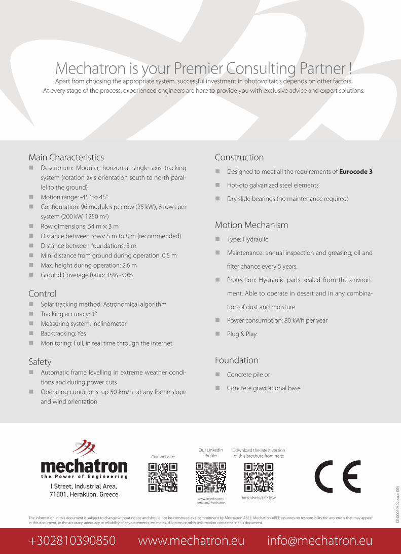
Main Characteristics � Description: Modular, horizontal single axis tracking
system (rotation axis orientation south to north paral-
lel to the ground)
� Motion range: -45° to 45°
� Configuration: 96 modules per row (25 kW), 8 rows per
system (200 kW, 1250 m2)
� Row dimensions: 54 m × 3 m
� Distance between rows: 5 m to 8 m (recommended)
� Distance between foundations: 5 m
� Min. distance from ground during operation: 0,5 m
� Max. height during operation: 2,6 m
� Ground Coverage Ratio: 35% -50%
Control � Solar tracking method: Astronomical algorithm
� Tracking accuracy: 1°
� Measuring system: Inclinometer
� Backtracking: Yes
� Monitoring: Full, in real time through the internet
Safety � Automatic frame levelling in extreme weather condi-
tions and during power cuts
� Operating conditions: up 50 km/h at any frame slope
and wind orientation.
Construction
� Designed to meet all the requirements of Eurocode 3
� Hot-dip galvanized steel elements
� Dry slide bearings (no maintenance required)
Motion Mechanism
� Type: Hydraulic
� Maintenance: annual inspection and greasing, oil and
filter chance every 5 years.
� Protection: Hydraulic parts sealed from the environ-
ment. Able to operate in desert and in any combina-
tion of dust and moisture
� Power consumption: 80 kWh per year
� Plug & Play
Foundation
� Concrete pile or
� Concrete gravitational base
I Street, Industrial Area, 71601, Heraklion, Greece
The information in this document is subject to change without notice and should not be construed as a commitment by Mechatron ABEE. Mechatron ABEE assumes no responsibility for: any errors that may appear in this document, to the accuracy, adequacy or reliability of any statements, estimates, diagrams or other information contained in this document. D
N00
0193
02 Is
sue
005
+302810390850 www.mechatron.eu [email protected]
www.linkedin.com/company/mechatron
Our website:
Our LinkedInProfile:
Download the latest version of this brochure from here:
http://bit.ly/1KIXTpW
Mechatron is your Premier Consulting Partner !Apart from choosing the appropriate system, successful investment in photovoltaic’s depends on other factors.
At every stage of the process, experienced engineers are here to provide you with exclusive advice and expert solutions.
