Embed Size (px)
DESCRIPTION
Appropriate Technology Library - Instructions for building a solar water heather
Citation preview
A project of Volunteers in Asia
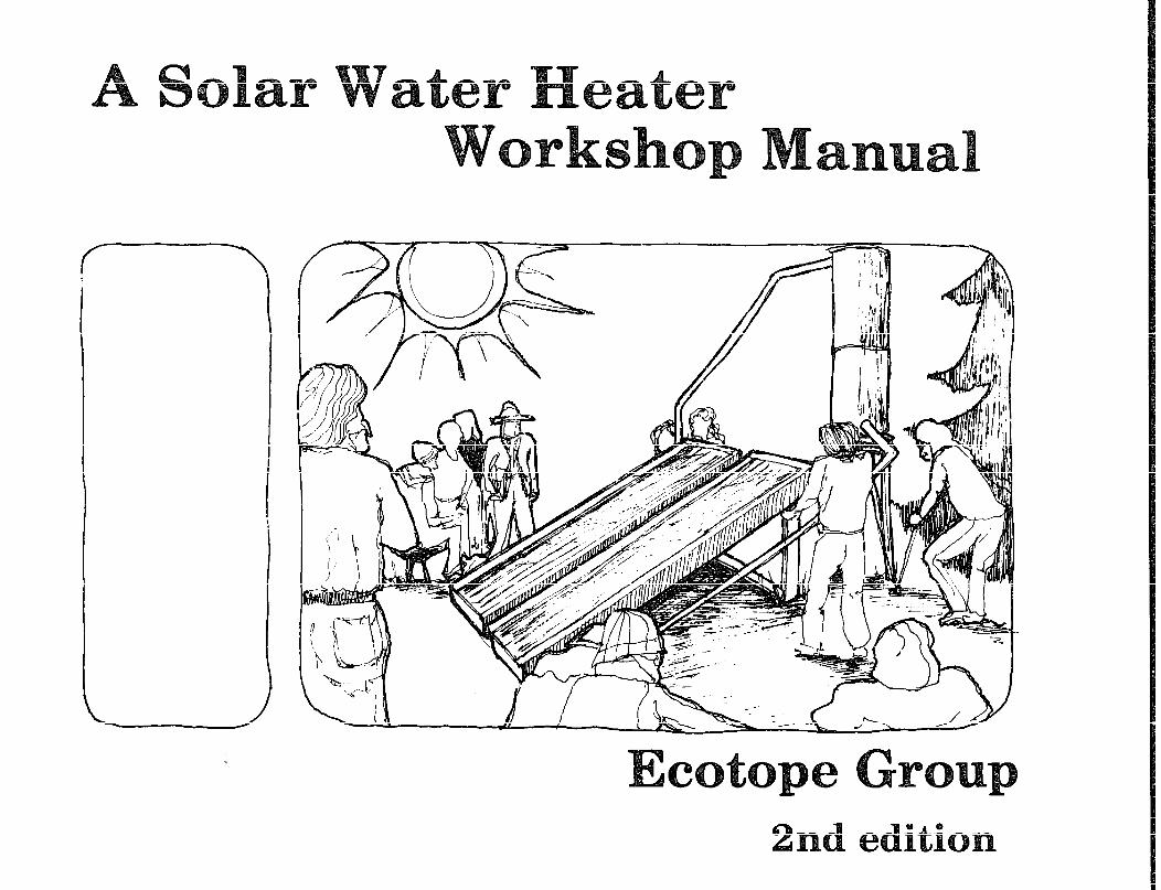
A Solar Water Heater Workshop Manual
by Ken Eklund et. al.
Published by:
Ecotope Group 2812 East Madison Seattle, Washington 98112 USA
Available from:
same as above
Reproduced by permission.
Reproduction of this microfiche document in any form is subject to the same restrictions as those of the original document.
#--
TEXT BY: Ken Eklund, with David Baylon, Belinda Boulter, Stuart Gustafson, Bruce Lampcov, and Randy Skoog
GRAPHICS: Carol Oberton
EDITING, LAYOUT AND TYPING: Annie Stewart and Richard Sassaman
Based on the Ecotope/RAIN Solar Workshop Manual of September 1976, by Ken Smith and Lee Johnson, including their substantial revision work.
Special thanks to Christopher Mattock of Solar Design and Applications Ltd., Vancouver, B.C., for sharing design information and permission to use the graphics noted below.
(The f a 2 Zowing drawings, Z&ted as numbered in the text, are from the pre2imGaaq draft of a book on so2ar water heaters by Chxis Mattock for B.C. Hydra, and are used with the author’s permCssion: the figure or”; page 5, and f<gures 5, 6, 7, 6, 9, 10, 14, 21, 22, 23 & 24.)
Second edition copyright 1979
Why Build A Solar Water Heater?
How Does A Solar Water Heater Work?
Will A Solar Water Heater Save Money?
How To Build And Install A Solar Water Heater
Step By Step Instructions
Material 3
Alternative Designs
How To Site Yol!r Hot Water System
Your Collector and the Code
Location Options and Considerations
The System's Piping
Active Systems
1
2
5
6
10
23
24
27
36
37
36
53
Freeze Protection
Heat Exchangers
Commercial Systems
Maintenance
Hot Water Conservation
What Happens When There's No Sun?
Organizing A Workshop
Tools
Access
Further Reading
Feedback
57
60
64
66
67
69
70
77
78
80
81
Right now we are changing the way we use energy, and the kinds of energy we use. Lately there has been an emphasis on conserving energy, while at the same time plans are being put forward for mass expansion of production in order to supply energy at our present use levels. We are developing energy sources-- coal. nuclear, oil shale and solar in all of its forms (wind, plant fuel, direct, and electricj-- different from those recently rel ied upon.
The cost of energy has climbed and will continue to increase. This is due mainly to the restricted supply of conventional fuels and the high cost of electricity from electric generating plants operated by heat (thermal plants). This electricity is expensive because of the large construction costs and because only about 40% of the heat energy put in comes out as electricity.
Since we are in an important time of change, we have the opportunity to make both better use of energy and to find better sources.
Better Uses of Energy What is commonly called “conservation” is really an effort to stop the leaks, to eliminate waste. But we can also do an incredible amount of conserving by eliminating the amount of unusuable energy we create. We can do this through matching the energy source to the most appropriate energy use, The idea here is that we first determine the minimum amount of energy needed to do a specific job, and then find an energy source that can supply the energy needed for the job while losing the least amount of energy along the way.
Let’s say we have two energy sources that can give us the same amount of enerpv-- one cubic foot of natural gas and one day’s collected energy from one ft2 of solar collector. (The actuzi value depends on the month, the geographical location, and the position of the collector.) We want to heat our water for washing dishes and bathing.
The natural gas burner operates at iOOO’F., while the solar collector operates at 120’F. (once again depending on several factors). The gas burner will lose more heat than the collector because the hotter an object is, the more heat it will give off to thz environment. So, even though the cubic foot of natural gas contains the same amount of energy as the square foot of collector will supply per day, we will have to burn more natural. gas to compensate for the heat it gives off to the environment. As you can see, our low temperature solar collector is more appropriately matched to the job of heating water than is the natural gas flame.
Another way to better use energy is to decentralize the process of converting energy into forms for doing work. This can offer opportunities to use waste heat and will cut transportation and transmission costs.
Better Sources of Energy Our present fossil fuels are: 1) nonrenewable; 2) environmentally harmful in extraction,
transportation and use, and 3) require expensive and centrally located
efforts to extract and transport.
More desirable sources would : 1) be renewable; 2) have a low impact on the environment in all
phases of production and use;
3) be converted as closely as possible to the point of energy use;
4) be labor intensive rather than capital intensive (make jobs); and
5) be controlled by the people who use it.
Solar Energy Solar energv iJJ its various forms can qualify both as a better source and a better use of energy in many appl icut ions. Individual, on-site collection systems (like ollr water heater) can supply heat at temperatures adequate for space and water heating with simple. direct conversion of light to heat -- without using greater temperatures than we need for the job.
Electricity can be produced by the direct conversion of the mechanical energy in wind through windmills or (in the future) through quantum conversion, as in photovoltaic cells. lligh temperatures can be supplied by focusing collectors and by fuels supplied from growing plants. tlowevcr, if we attempt to supply al 1 of our energy needs by constructing large, high temperature electrical generation facilities powered by the sun, we could run into many of the problems associated with our present fossil fuel technology.
So how do we begin implementing a better energy solution? Stopping waste is an important step no matter what else we do. Coupled with conservation, we can begin to take advantage of the sun’s energy. The solar water heating system described in this manual is a concrete project that can supply energy to help reduce your water heating bill-- the reduction in your bill will show the contribution to conservation that you are making.
By building and installing the water heater yourself, you will save one-half to two-thirds the cost of a high quality commercially available system, and still receive three-quarters of the energy that the best systems can give you. You will also gain an understanding of solar energy and of how your system works-- plus the skills and experience acquired in building and installing it that you can get no other way.
How Does a Solar ater Heater Work?
First, some basic terms:
Heat: the form of energy whose effect is the rel3tive motion of molecules.
Temperature: the measure of the degree of the effect of heat.
BTU (British Thermal Unit): the amount of heat needed to raise the temperature of one pound of water one degree Farenheit. (In the metric system, heat energy is now measured in Joules. One BTU= 1,055 Joules.)
The major rule in heat transfer is the Second Law of Thermodynamics: heat will flow from warmer bodies to cooler ones. The greater the temperature difference, the greater the heat flow. There are three pathways for this transfer of heat:
1) Convection is the transfer of heat by the mass movement of the heated particles. An example is a cool breeze on a hot day.
2) Radiation is a net transfer by electromagnetic waves that will be given off by particles with higher heat, and absorbed by particles with less
heat. An example of this-- warming yourself in front of a fire.
3) Conduction is the transfer of heat from one particle to another by direct contact. An example of this is burning your finger on a stove.
All solar systems must have some kind of collector to catch solar energy (which arrives mainly in the form of light) and convert it to heat. Solar systems must also have some way to move the heat a.nd a way to store it until it is needed. There are many different ways to do each of these things, but we will focus here on the system described in this manual.
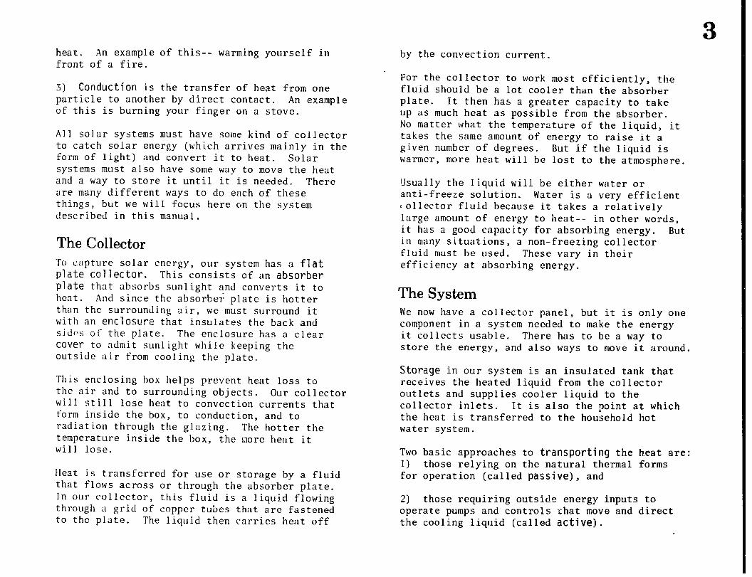
The Collector To capture solar energy, our system has a flat plate collector. This consists of an absorber plate that absorbs sunlight and converts it to heat . And since the absorber; plate is hotter than the surrounding air, we must surround it with an enclosure that insulates the back and sides of the plate. The enclosure has a clear cover to admit sunlight while keeping the outside air from cooling the plate.
This enclosing box helps prevent heat loss to the air and to surrounding objects. Our collector will still lose heat to convection currents that form inside the box, to conduction, and to radiation through the glazing. The hotter the temperature inside the box, the I;lore heat it will lose.
Heat is transferred for use or storage by a fluid that flows across or through the absorber plate. In our collector, this fluid is a liquid flowing through a grid of copper tubes that are fastened to the plate. The liquid then carries heat off
by the convection current.
For the collector to work most efficiently, the fluid should be a lot cooler than the absorber plate. It then has a greater capacity to take up as much heat as possible from the absorber. No matter what the temperature of the liquid, it takes the same amount of energy to raise it a given number of degrees. But if the liquid is warmer, more heat will be lost to the atmosphere.
Usually the liquid will be either water or anti-freeze solution. Water is a very efficient 1 ollector fluid because it takes a relatively large amount of energy to heat-- in other words, it has a good capacity for absorbing energy. But in many situations, a non-freezing collector fluid must be used. These vary in their efficiency at absorbing energy.
The System We now have a collector panel, but it is only one component in a system needed to make the energy it collects usable. There has to be a way to store the energy, and also ways to move it around.
Storage in our system is an insulated tank that receives the heated liquid from the collector outlets and supplies cooler liquid to the collector inlets. It is also the point at which the heat is transferred to the household hot water system.
Two basic approaches to transporting the h.eat are: 1) those relying on the natural thermal forms for operation (called passive), and
2) those requiring outside energy inputs to operate pumps and controls ehat move and direct the cooling liquid (called active).
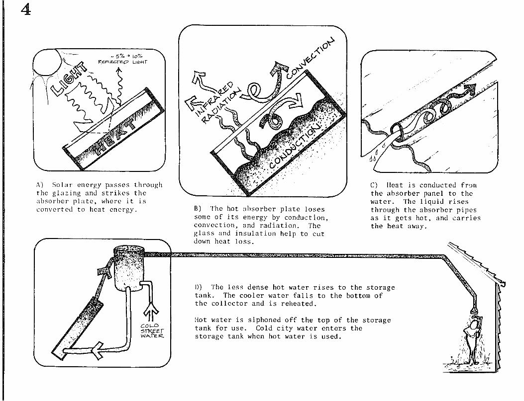
A) Solar energy passes t.hrough the glazing and strikes the absorber plate, where it is convcrtcd to heat energy.
/ C) lleat is conducted from the absorber panel to the water. The liquid rises
B) The hot absorber plate loses through the absorber pipes some of its energy by COndUCt ion, as it gets hot, and carries convection, and radiation. The the heat away. glass and insulation help to cut down heat loss.
D) The less dense hot water rises to the storage tank. The cooler water falls to the bottom of the collector and is reheated.
:Iot water is siphoned off the top of the storage tank for use. Cold city water enters the storage tank when hot water is used.
The system we recommend wherever it can be used is a passive natural flow system called a thermosiphon. It is less expensive than an active system because it requires no pumps or controls to make it work. Because it is less complex, it is easier and cheaper to maintain.
The driving force behind the thermosiphon is convection. Colder water in the bottom of the storage tank sinks to the bottom of the collector panels. As it does this, it pushes up the warmer water (which is lighter) in the panel. This water will rise into the storage tank, creating the circuit demonstrated
-__ ---.-- - -_ below.
ar ates ter ve Money?
To analyze an invcstmcnt in solar energy, several important vari lhles must be consider-e. :
1) The cost of the system. 2) ‘l’!lc cncrgy gcncratcd (saved) by that system. 3) The cost of that energy at present. -1) The cost of that energy in the future. 5) The interest rates and inflation rates
;ISSOC‘ iated with the investment.
Using these variables, a payback period can be computed. The payback period is the number of years of energy savings required to cause the system to break even, and return in energy savings the invested capital plus interest.
In general, if this payback period Js less than the life of the collectors (20 years), then the investment is justified. Payback analysis is a 1 ife cycle cost procedure that gives economic comparisons based on a common set of assumptions about the future. Different assumptions yield different results.
The Economics of Solar Hot Water The use of solar panels for water heating presents one of the most cost effective means of using flat plate solar collector technology in theNorthwcst climate. This is largely because the demand for hot water is fairly uniform year round, and the flat plate collector can be used in late spring, summer and fall to produce virtually all the hot water required by a residence.
The variation in costs, however, makes careful selection of a collector more critical. In genera 1 , a durable collector without costly frills [such as selective surface coatings, sophisticated glazing configurations or other amenities) has an economic payback period of eight to 12 years. The extras have their place, but generally it is a sunnier climate that provides their justification. These more expensive systems when used for water heating have payback periods of 12 to 20 years.
Table 1 summarizes the payback periods associated with a system similar to the one built in this workshop.
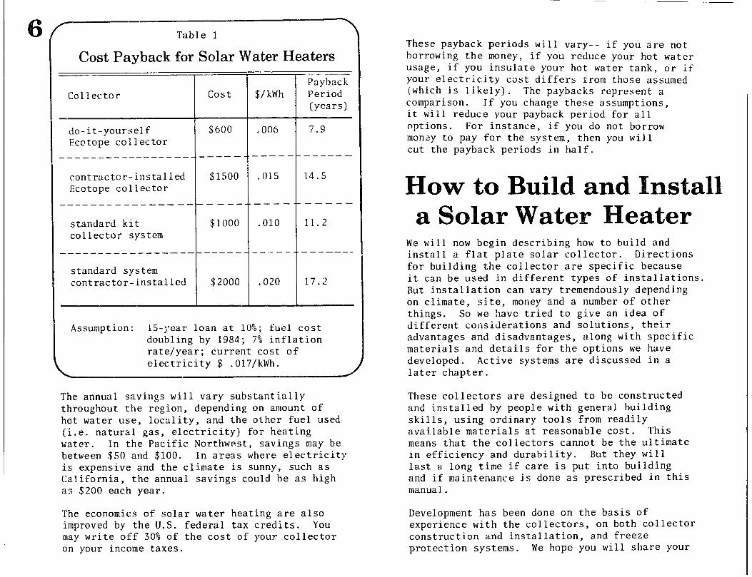
Table 1
Cost Payback for Solar Water Heaters --
Co1 lector
- --- Payback
cost $/kWh Period (years)
do-it-yourself $600 .006 7.9 Ecotope collector
.___________ ------.-em---.----- -------
contractcr-installed $1500 .015 14.5 Ecctope collector
.--------__----- -- ------- ---------
standard kit $1000 .OlO 11.2 collector system
____-_ --- ____- ---_--------v--T-------
standard system contractor-installed $2000 ,020 17.2
Assumption: 15-year loan at 10%; fuel cost doubling by 1984; 7% inflation rate/year; current cost of electricity $ .017/kWh.
The annual savings will vary substantially throughout the region, depending on amount of hot water use, locality, and the other fuel used (i.e. natural gas, electricity) for heating water. In the Pacific Northwest, savings may be between $50 and $100. In areas where electricity is expensive and the climate is sunny, such as California, the annual savings could be as high as $200 each year.
The economics of solar water heating are also improved by the U.S. federal tax credits. You may write off 30% of the cost of your collector on your income taxes.
These payback periods will vary-- if you are not borrowing the money, if you reduce your hot water usage, if you insulate your hot water tank, or if your electricity cost differs from those assumed (which is likely). The paybacks represent a comparison. If you change these assumptions, it will reduce your payback period for all options. For instance, if you do not borrow money to pay for the system, then you will cut the payback periods in half.
We will now begin describing how to build and install a flat plate solar collector. Directions for building the collector are specific because it can be used in different types of installations. But installation can vary tremendously depending on climate, site, money and a number of other things. So we have tried to give an idea of different considerations and solutions, their advantages and disadvantages, along with spec materials and details for the options we have developed. Active systems are discussed in a later chapter.
ific
These collectors are designed to be constructed and installed by people with general building skills, using ordinary tools from readily available materials at reasonable cost. This means t in effi last a and if manual.
hat the collectors cannot be the ultimate ciency and durability. But they will long time if care is put into building maintenance is done as prescribed in this
Develop sment has been done on the basis of experience with the collectors, on both collector construction and installation, and freeze protection systems. We hope you will share your
a ideat; and experiences with us. There’s a form at the back of this manual for you to give us feedback
Materials Purchase
We have done our best to give you a complete materials list for collector construction. Installation varies too much for us to give complete directions or a specific materials list. But we have identified special items and manufacturers so that you can find them. The material quantities in the collector instructions are for one panel (except for paint).
The section on piping lists items basic to any system. The freeze protection discussion gives a fairly specific idea of what is needed for the option you choose.
To build and install these collectors, you will be buying large quantities of copper tubing and plumbing supplies and glass. Try to get them wholesale--shop for good prices. Be especially careful when you buy glass. Prices vary greatly and the unwary may be taken. If you have trouble getting materials and hardware at reasonable prices, consider forming a buying club with your neighbors so you can buy wholesale.
Wherever possible, use recycled materials. Tanks I glass, even wood and pipe can be found for free or almost nothing. The design may have to be modified to take advantage of recycled materials such as tempered glass. If you use recycled materials be sure they are in good condition.
Collector Design and Construction Our panels have undergone a lot of development.
We changed from steel pipe to copper tubing to make use of easier soldering connections and to increase heat conductions. We tried various ways of binding the tubes to the plate: thermal mastic did not hold up well and solder bonds broke because copper expands more than steel. We have also found corrosion at the solder joints. We now wire the tubes to the plate.
The insulation has been changed from Styrofoamtm to fiberglass batts. The fiberglass is cheaper, more available, and does not evaporate in high heat as the Styrofoam was found to do.
The glazing detail has been changed to make use of new materials. Instead of caulk that deteriorates rapidly, we are now using butyl glazier’s tape, which is very easy to install and holds up well. We arc now experimenting with some new inner glazings and methods of application, But the general approach is still the same: to build a box with standard size lumber that is strong enough to support itself. A separate cover is used to make the collector more easily transportable (two lighter pieces rather than one heavy piece) and to facilitate servicing the collector plate.
To make the collectors as durable as possible, be sure to prime and paint them carefully. In a workshop setting two coats of exterior latex are the only feasible treatment. In both cases pressure treated wood should be considered.
Glazing: Some Notes
Glazing is the transparent or translucent material used to cover the solar collector. This glazing can be rigid like glass, semi-rigid like
fiberglass-reinforced plastic (“Kalwall ,I’ “Filon,” “Lascolite”), or thin, flexible film-like polyethylene, polyester (“Mylar”), and polyvinyl fluoride (“Teflon,” “Tedlar”).
Glazing primarily must allow light rays from the sun to enter the collector, and prevent heat from leaving. Hence, the two most important features to consider are maximum transmission of solar radiation (i.e., short-wave or ultraviolet) and minimum loss of heat radiation (i.e., thermal, long-wave or infrared). Other important factors are the useful life of the material, the ease of installation, and cost.
Two influences on the ability of the material to let light through (solar transmissivity) are reflection and absorption of light rays by the glazing material. Reflect ion should be kept to a minimum, It is important that the glazing r?ateri.al accept both direct radiation from the s.un and a large percentage of diffuse light from the whole sky.
Diffuse light is especially important in a climate with relatively few completely clear days (like the Maritime Northwest). Fiberglass has a comparatively high reflectivity (especially of diffuse radiation), while glass and polyvinyl fluoride have lower reflectivity.
Absorption of light rays by the glazing material can be caused by impurities in the material, but it is most often due to changes in the material’s chemical structure. Exposure to ultraviolet rays, air pollution and heat can cause these changes. Materials most likely to change are polyethylene, acetate, Mylar and vinyl. Glass is almost completely unaffected by these problems. Glazing-grade fiberglass is usually treated to
withstand ultraviolet exposure. If you use it, make certain it has been factory-treated in this way.
Most common glazing materials are poor reflectors of thermal radiation, although some (like glass) can absorb the hot infrared rays and re-radiate part of them to the interior. Glazing usually does not keep heat in by reflecting it, but by suppressing the convection of air currents. Two layers of glazing are commonly used because air trapped between the two layers is not allowed to convect in the small space between them. The air space thus acts as insulation and goes a long way toward preventing heat losr. Three layers of glazing can be effective in very cold ciimates. but the added 1 ayer will also reduce light transmission and raise the cost of the collector. IVe have already mentioned that some glazing materials have greatly reduced transmijsivity after prolonged exposure to light, heat or pollution. Many also physically deteriorate either because of ultraviolet radiation or mechanical stress.
Glass, although resistant to the elements, is very susceptible to breakage by hail, birds, or vandalism. Tempered glass can reduce this probler, considerably. Fiberglass is very vulnerable to surface erosion unless it is specially treated. Fiberglass will also sag under heat expansion and snow loading unless it is corrugated to add rigidity.
Films can stretch or become distorted, creating stress and. breakage. Polyethylene, though cheap, has a very short lifetime and will virtually disintegrate when exposed to weathering. Acrylic plastics, though very break resistant, expand too much to be desirable in a solar collector that
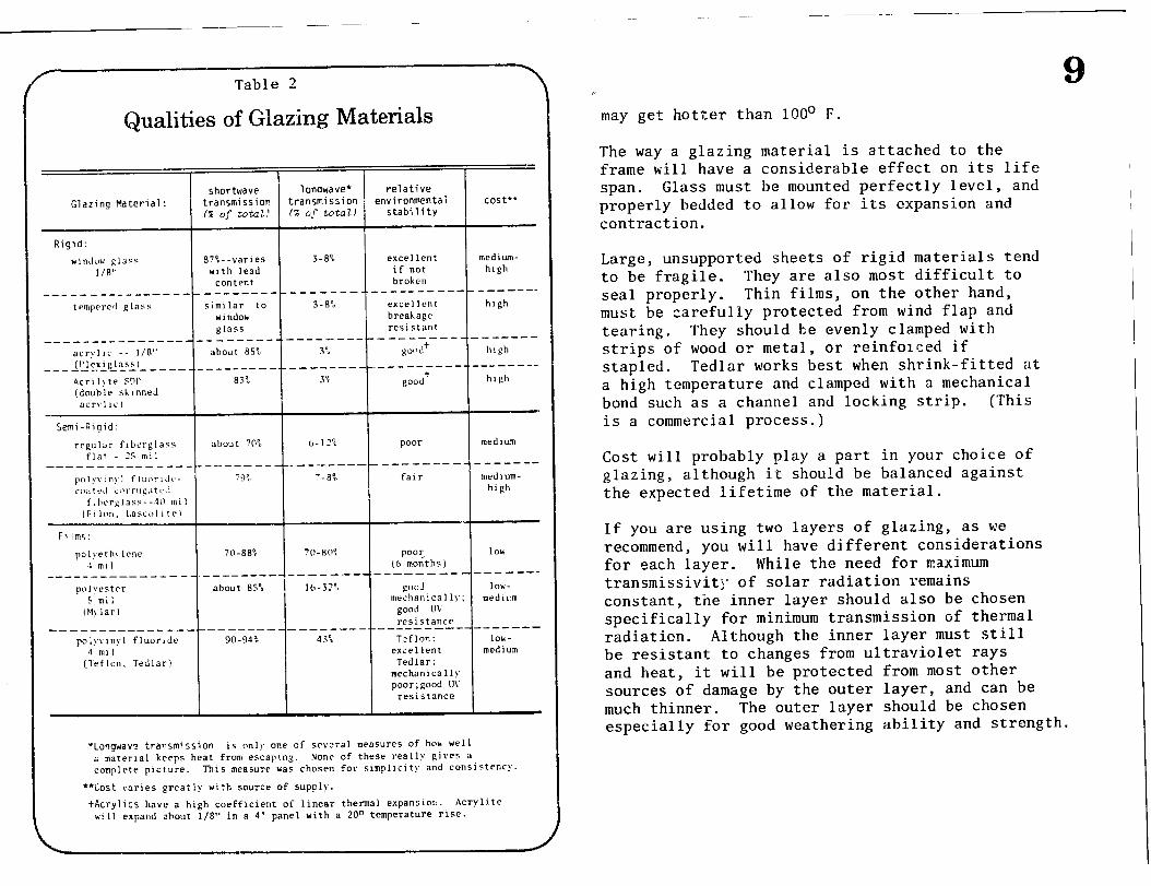
Table 2
Qualities of Glazing Materials
Glazing Material: shortwave longwave* relative
transmission transmission f environmental cost** c% of total! (% of total) stability
Rigid:
w1nJov RI"" a?%- -varies 3-8”. excellent medium- l/8” wirh lend if not high
content broken ______________________ --e-_----7- -.-- ----------------
tempered glass similar to 3-a”, excellent high windok breakage glass resistant
____________ ---B-e-------.-------- __-__---___- e---m
acrylic -- l/A” about 855 3% pmi+ hlCh (Plexlglas5l ------~___--- ____ _______ -_-_---VW-----.--------- _.------__
Acrllyte FM’ as?, 3% good+ high (douhlr sl,lnned
acyllrl
Semi-Rlqid:
regular fIberglass about 70% 6-l’% poor medium flat - 15 m:l
---- _______ ____ ____ - __________ --------m-----e-----
pol)T:nyl flillll.IJc- -9: ‘-8% fair medium- ccm1rJ it,rruf.it c.4 high
f.hcrglass--30 mil (FI 1~. Larcoll lel
Films:
polvcth>Icqe 70-88% 7n-RIIO. roe:, 1OW 4 ml1 (6 !nonths)
________________ ___- ____- ---- -----0-e ------------
po1yestcr about 85% 1 1 6 - 3 ? 18 pd lOk- 5 ml; mechanically; medium
(Mylar1 good II\ resistance -______________________^___I -__-__----_--~~~-~~~~--
poly\~nyl fluoride 90-94: 43% Tzflcvl: lov- 4 ml1 excellent medium
(Teflon. Tedlar) Tedlar: mechanicall! poor ; good U\
resistance
*Longwav? transmission is onl!, one of several measures of ho* well a material keeps hear from escaping. None of these really gives a complete picture. This measure *as chosen for slmpllcity and consistency.
**Cost varies greatly with source of supply.
tAcrylics have a high coefficient of linear thermal expansln!A. Acrylite will expand abour l/E” in a 4’ panel with a 20” temperature rise.
9 may get hotter than 100’ F.
The way a glazing material is attached to the frame will have a considerable effect on its life span. Glass must be mounted perfectly level, and properly bedded to allow for its expansion and contraction.
Large, unsupported sheets of rigid materials tend to be fragile. They are also most difficult to seal properly. Thin films, on the other hand, must be carefully protected from wind flap and tearing. They should be evenly clamped with strips of wood or metal, or reinforced if stapled. Tedlar works best when shrink-fitted at a high temperature and clamped with a mechanical bond such as a channel and locking strip. (This is a commercial process.)
Cost will probably play a part in your choice of glazing, although it should be balanced against the expected lifetime of the material.
If you are using two layers of glazing, as we recommend, you will have different considerations for each layer. While the need for maximum transmissivit]? of solar radiation remains constant, the inner layer should also be chosen specifically for minimum transmission of thermal radiation. Although the inner layer must still be resistant to changes from ultraviolet rays and heat, it will be protected from most other sources of damage by the outer layer, and can be much thinner. The outer layer should be chosen especially for good weathering ability and strength.
Materials
one 8’ 2x6, standard
two 8’ 2x6, standard
one tube of Bui lder’ s Adhesive
8 - #10x2’/,” flathead, galvanized wood screws
one 4’x8’ sheet 3/8” CDX plywood
$ lb. 6d galvanized common nai 1s
12’ of l”x4” molding (it need not be clean fir-- use any’ kinll of 1x,1)
6 - (1 10x2’2” f woodscrcws
‘lathcad
L gallon exterior latex paint -- or if time permits, an enamel primer
1.1
lnstructlons
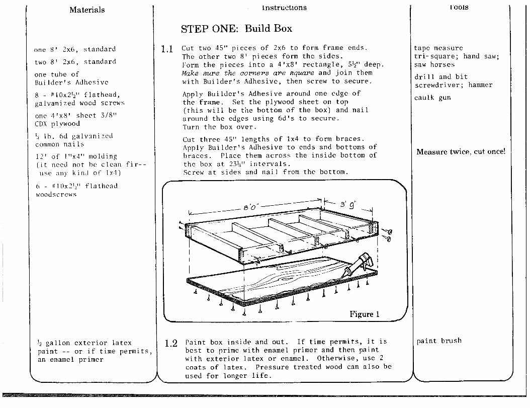
STEP ONE: Build Box
Cut two 45” pieces of 2x6 to form frame ends. The other two 8’ pieces form the sides. Form the pieces into a 4*x8’ rectangle, !&‘I deep. Make sure the comers are square and join them with Builder’s Adhesive, then screw to secure.
Apply Builder’s Adhesive around one edge of the frame. Set the plywood sheet on top (this will be the bottom of the box) and nail around the edges using 6d’s to secure. Turn the box over.
Cut three 45” lengths of 1x4 to form braces. Apply Builder’s Adhesive to ends and bottoms of braces. Place them across the inside bottom of the box at 23$” intervals. Screw at sides and nail from the bottom.
Figure 1
1.2 Paint box inside and out. If time permits, it is best to prime with enamel primer and then paint with exterior latex or enamel. Otherwise, use 2 coats of latex. Pressure treated wood can also be used for longer life.
1’001s
:ape measure :ri- square; hand saw; ;aw horses
lrill and bit screwdriver ; hammer
:aulk gun
Measure twice, cut once!
paint brush
two 10’ lengths and one 1.2’ length (32’ total) of 1 ‘x2!’ clear fir molding
8 . #6x3/4” galvanized f lathead woodscrews
glue (recommend: Wilhold Marine Plastic Resin)
ix2 molding from Step 2.1
t.wo #6x3/4” galvanized flathead woodscrews
glue
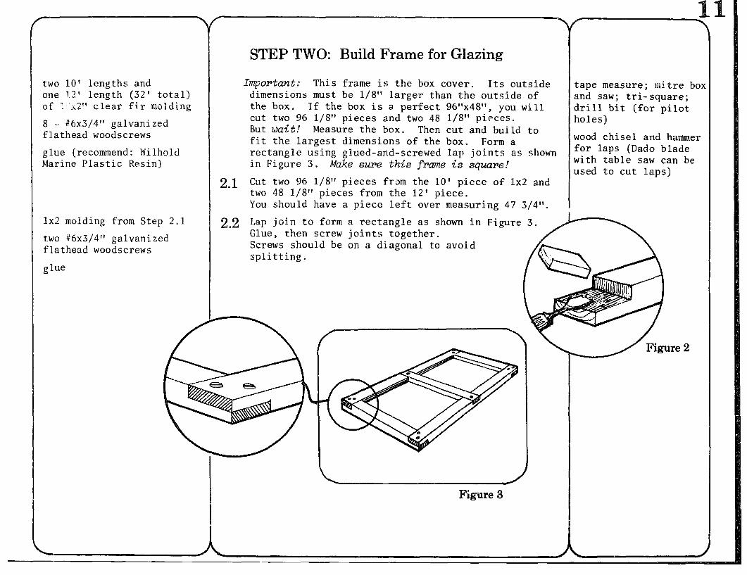
STEP TWO: Build Frame for Glazing
Important: This frame is the box cover. Its outside dimensions must be l/8” larger than the outside of the box. If the box is a perfect 96”x48”, you will cut two 96 l/8” pieces and two 48 l/S” pieces. But wait! Measure the box. Then cut and build to fit the largest dimensions of the box. Form a rectangle using glued-and-screwed lap joints as shown in Figure 3. Make sure this frame is square!
2.1 Cut two 96 l/S” pieces from the 10’ piece of 1x2 and two 48 l/8” pieces from the i2’ piece. You should have a piece left over measuring 47 3j4”.
I 2.2 Lap join to form a rectangle as shown in Figure 3.
Glue, then screw joints together. Screws should be on a diagonal to avoid splitting.
tape measure; mi tre box and saw; tri- square; drill bit (for pilot holes)
wood chisel and hammer for laps (Dado blade with table saw can be used to cut laps)
three 10’ lengths of l”x3” Fir
zlue
ten #8x1$” galvanized Flathead woodscrews
4d finish nails
paint from Step 1.3
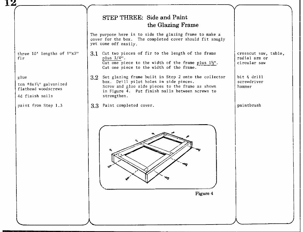
STEP THREE: Side and Paint the Glazing Frame
The purpose here is to side the glazing frame to make a cover for the box. The completed cover should fit snug yet come off easily.
3.1 Cut two pieces of fir to the length of the frame plus 3/4”. Cut one piece to the width of the frame plus l&“. Cut one piece to the width of the frame.
3.2 Set glazing frame built in Step 2 onto the collector box. Drill pilot holes in side pieces. Screw and glue side pieces to the frame as shown in Figure 4. Put finish nails between screws to strengthen.
3.3 Paint completed cover.
Figure 4
crosscut saw, table, radial arm or circular saw
bit E drill screwdriver hammer
paintbrush
2 ft2 of R-11 foilbacked iberglass insulation If only 16” width is avail- dble instead of 24”, cut 6 pieces to length. Cut 2 in half to fill the boxes.)
:wo 8 1 x20’* corrugated galvanized steel roofing
10 - #6&” galvanized ;heet metal screws
vinegar, galvanized metal preparation or a weak solution of muriatic acid
one pint flat black ename 1, high quality, high temperature (recommend: Rustoleumt, or Sherwin- Williams industrial flat black) *
4.1
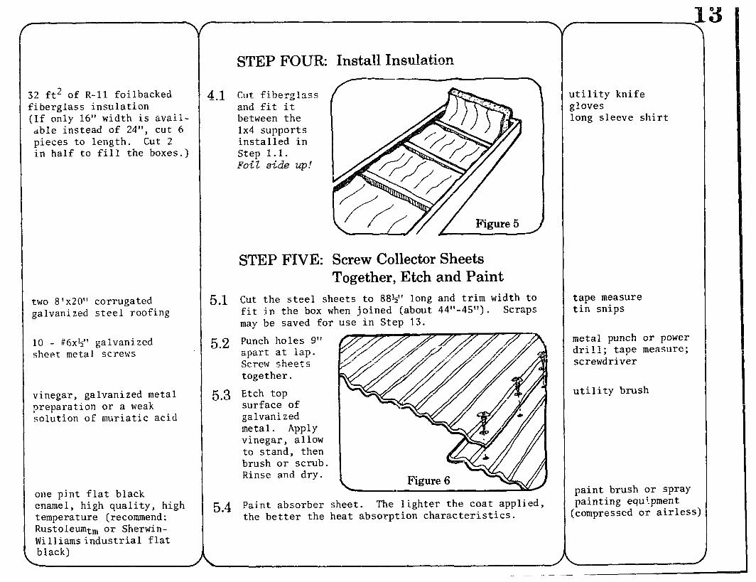
STEP FOUR: Install Insulation -
Cut fihm-‘ass UW2&1
and fit it between the 1x4 supports installed in Step 1.1. Foil side up!
STEP FIVE: Screw Collector Sheets Together, Etch and Paint
5.1 Cut the steel sheets to 88%” long and trim width to fit in the box when joined (about 44”-45”) . Scraps may be saved for use in Step 13.
5 2 Punch holes 9” . apart at lap. Screw sheets together.
5.3 Etch top surface of galvanized metal. Apply vinegar, allow to stand, then brush or scrub. Rinse and dry.
5.4 Paint absorber sheet. The lighter the coat applied, the better the heat absorption characteristics.
utility knife gloves long sleeve shirt
tape measure tin snips
metal punch or power dri 11; tape measure; screwdriver
utility brush
paint brush or spray painting equi-pment
(compressed or airless)
r
three 20’ sections of 2’ rigid copper tubing, Type M
flux
14 - 3/4”x3/4”x+” copper copper tees
(15 if the collector is to be used in a bank)
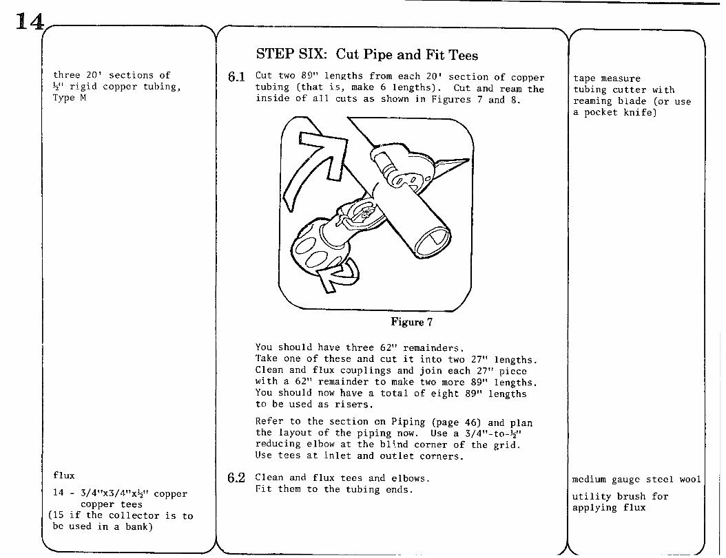
STEP SIX: Cut Pipe and Fit Tees 6.1 Cut two 89” lengths from each 20’ section of copper
tubing (that is, make 6 lengths). Cut and ream the inside of all cuts as shown in Figures 7 and 8.
Figure ‘i’
You should have three 62” remainders. Take one of these and cut it into two 27” lengths. Clean and flux couplings and join each 27” piece with a 62” remainder to make two more 89” lengths. You should now have a total of eight 89” lengths to be used as risers.
Refer to the section on Piping (page 46) and plan the layout of the piping now. Use a 3/4”-to-$” reducing elbow at the blind corner of the grid. Use tees at inlet and outlet corners.
6.2 Clean and flux tees and elbows. Fit them to the tubing ends.
tape measure tubing cutter with reaming blade (or use a pocket knife)
medium gauge steel wo(
utility brush for applying flux
7’ of 3/4” rigid copper tubing, Type M for manifold
flux
one roll of 50-50 solder not acid core (‘2 lb. of solder is more than enough for 2 collectors -- usually enough for a whole installation)
.
f
Fi
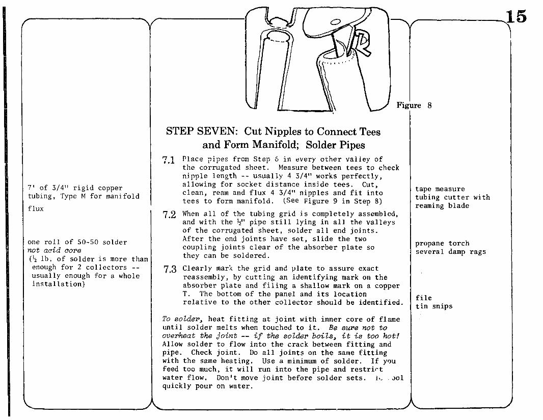
STEP SEVEN: Cut Nipples to Connect Tees and Form Manifold; Solder Pipes
7.1 Place wipes from Step 6 in every other valley of the corrugated sheet. Measure between tees to check nipple length -- usually 4 3/4” works perfectly, allowing for socket distance inside tees. cut, clean, ream and flux 4 3/4” nipples and fit into tees to form manifold. (See Figure 9 in Step 8)
7.2 When all of the tubing grid is completely assembled, and with the 3” pipe still lying in all the valleys of the corrugated sheet, solder all end joints. After the end joints have set, slide the two coupling joints clear of the absorber plate so they can be soldered.
7.3 Clearly mark the grid and plate to assure exact reassembly, by cutting an identifying mark on the absorber plate and filing a shallow mark on a copper T. The bottom of the panel and its location relative to the other collector should be identified.
To solder, heat fitting at joint with inner core of flame until solder melts when touched to it. Be sure not to overheat the joint -- if the solder boils, it is too hot! Allow solder to flow into the crack between fitting and pipe. Check joint. Do all joints on the same fitting with the same heating. Use a minimum of solder. If you feed too much, it will run into the pipe and restrict water flow. Don’t move joint before solder sets. in, 201 quickly pour on water.
ape measure ubing cutter w earning blade
ith
ropane torch everal damp rags
ile in snips
flux; solder
3’ of 3/4” rigid copper tubing, Type M
two 3/4”x3/4” copper male thread adapters (sweat fit) two 3/4” caps
one valve, 3/4” bronze
one hose adapter
one roll Teflon pipe seal tape
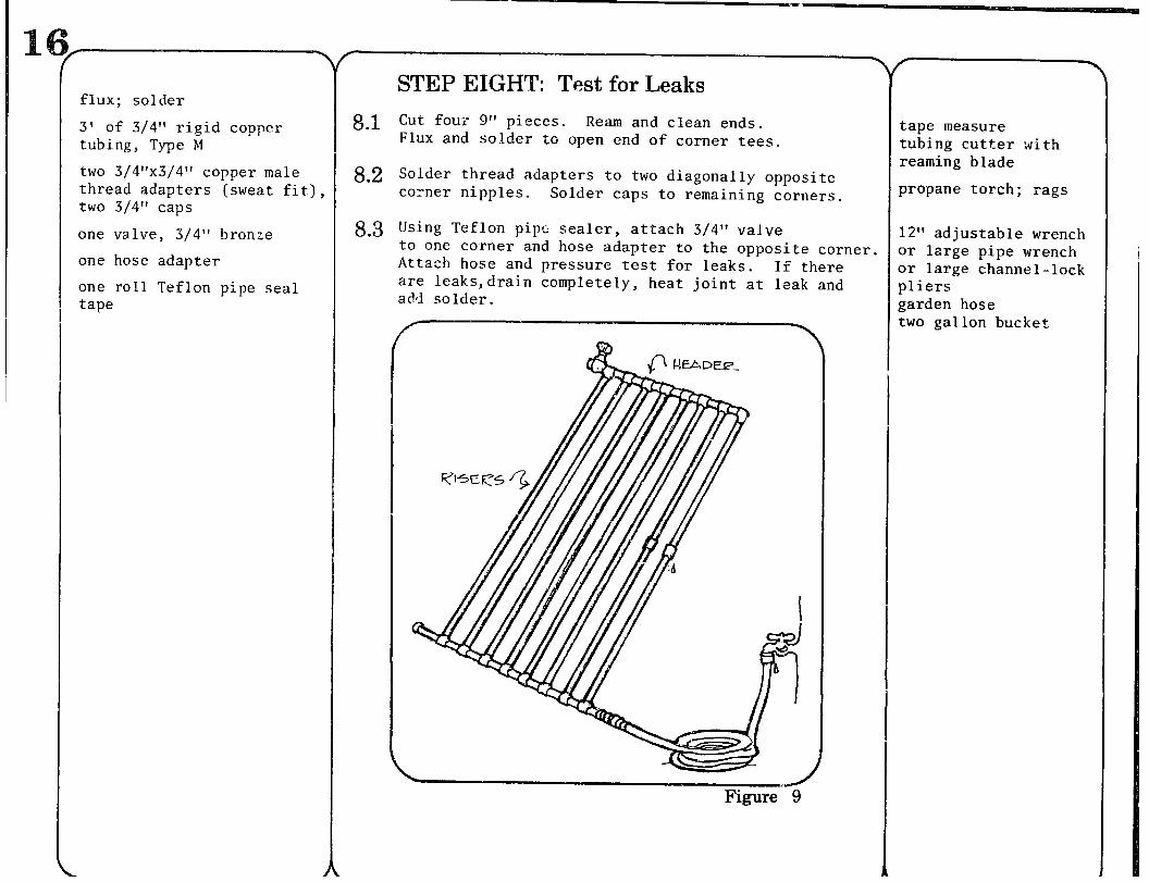
STEP EIGHT: Test for Leaks
8 .l Cut four 9” pieces. Ream and clean ends. Flux and solder to open end of corner tees.
8.2 Solder thread adapters to two diagonally opposite corner nipples. Solder caps to remaining corners.
8.3 Using Teflon pipe sealer, attach 3/4” valve to one corner and hose adapter to the opposite corner. Attach hose and pressure test for leaks. If there are leaks,drain completely, heat joint at leak and add solder ,
Figure 9
tape measure tubing cutter with reaming blade
propane torch; rags
12” adjustable wrench or large pipe wrench or large channel-lock pliers garden hose two gallon bucket
one or two 3/4” copper sweat fit caps
flux
paint from Step 4
one roll 16 gauge copper lockwire (galvanized or stainless steel will also work)
STEP NINE: Prepare Grid to Put in BOX
9.1 Remove valve, adapters, and caps from the corners by heating the adapter sweat joint and pulling off.
9.2 Refer to Piping section and determine the precise layout of the installation. Determine the position of the inlets and outlets to the grid. Shorten and cap the corner nipples which will not be used.
9.3 Clean all flux from the pipe grid. Rough the surface with steel wool. Paint the grid with a brush or spray application.
STEP TEN: Attach Pipe Grid to Absorber Plate
lo.1 Place pipe grid on absorber plate. Punch holes no more than 1,” apart on either side of 1,” pipes every 6”.
10.2 Insert wire and fasten the pipe to the absorber plate. Since the wire is lightweight, use minimal force.
propane torch
pipe cutter solder equipment
medium coarse steel wool ; spray paint gear or paint brushes
metal punch hammer
wire cutters pliers
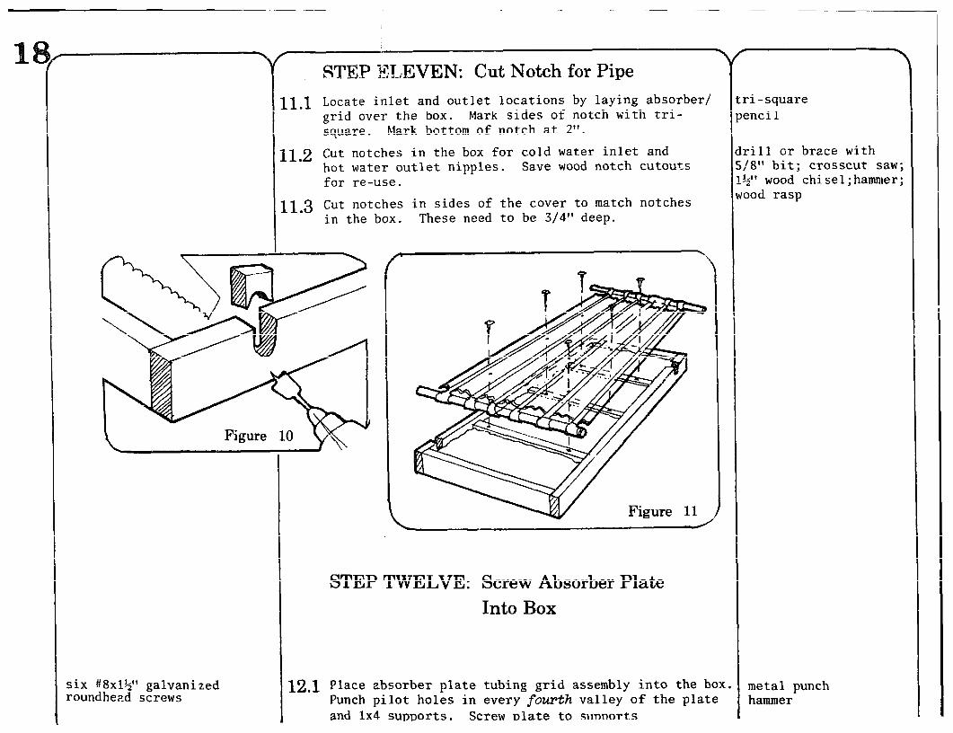
STEP ELEVEN: Cut Notch for Pipe
Locate inlet and outlet locations by laying absorber/ grid over the box. Mark sides of notch with tri- square. Mark bottom of notch at 2”.
Cut notches in the box for cold water inlet and hot water outlet nipples. Save wood notch cutouts for re-use.
Cut notches in sides of the cover to match notches in the box. These need to be 3/4” deep.
six #8x1?’ galvanized roundhead screws
12.1
STEP TWELVE: Screw Absorber Plate Into Box
Place absorber plate tubing grid assembly into the box Punch pilot holes in every fourth valley of the plate and 1x4 supports. Screw elate to su~aorts
ri -square :nci 1
rill or brace with 18” bit; crosscut saw; 4” wood ;od rasp
chisel;hammer;
metal punch hammer
caulk and glue
wood notches from Step 10
nails
metal scraps from Step 5
cover bui It in Steps 2 and 3
8’ of 48” wide !i or 1 mil Teflon glazing
30’ of l”x1/8” neoprene sponge weatherstripping
one box 3/S” staples one box 9/16” staples (both heavy duty)
fiber strand tape
3M H463 adhesive transfer tape, 3/8” wide
.3.?
-3.2
14.1
STEP THIRTEEN: Seal Notches
Refit and glue wood notches. Caulk area around inlet
I
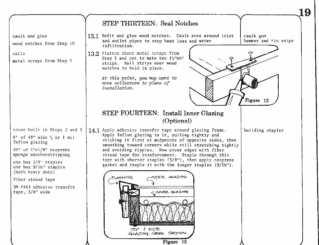
caulk gun and outlet pipes to stop heat loss and water hammer and tin snips infiltration.
Flatten sheet metal scraps from Step 5 and cut to make two l$“x6” strips. Nail strips over wood notches to hold in place.
At this point, you may want to move colZectors to place of installation.
STEP FOURTEEN: Install Inner G-lazing (Optional)
Apply adhesive transfer tape around glazing frame. Apply Teflon glazing to it, pulling tightly and sticking it first at midpoints of opposite sides, then smoothing toward corners while still stretching tightly and avoiding ripples. Now cover edges with fiber strand tape for reinforcement. Staple through this tape with shorter staples (3/8”), then apply neoprene gasket and staple it with the longer staples (9/16”).
Figure 13
I
Figure 12
3ui Id ing stapler
!5’ of 21Tx31’ L-flashing :or get 5” flat and bend it yourself)
30’ of Y’ butyl glazing tape
2 sheets of 48”x48” double strength glass or 48”x98” Lascolitetm or
Filon fiberglass glazing material
4 plastic mirror clips
4 brass screws
one tube of sili.cone caulk
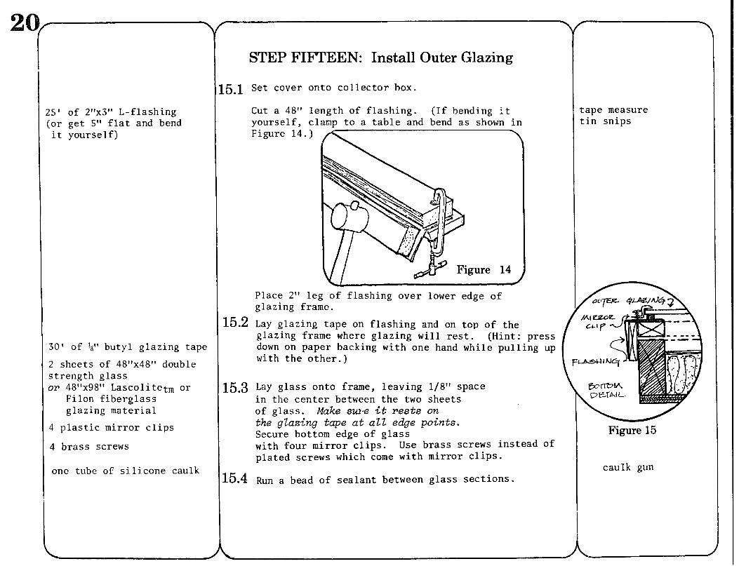
STEP FIFTEEN: Install Outer Glazing
-5.1 Set cover onto collector box.
Cut a 48” length of flashing. (If bending it yourself, clamp to a table and bend as shown in Figure 14.)
tape measure ti.n snips
Place 2” leg of flashing over lower edge of glazing frame.
15.2 Lay glazing tape on flashing and on top of the glazing frame where glazing will rest. (Hint: press down on paper backing with one hand while pulling up with the other.)
15.3 Lay glass onto frame, leaving l/8” space in the center between the two sheets of glass. Make sw-e it rests on the glazing tape at aZZ edge points. Secure bottom edge of glass with four mirror clips. Use brass screws instead of plated screws which come with mirror clips.
15.4 Run a bead of sealant between glass sections.
I i
flashing from Step 15
si iicone caulk
20’ butyl glazier’s tape
14 - #6 x Z/4” brass or hot dip galvanized roundhead woodscrews
STEP SIXTEEN: Install Flashing
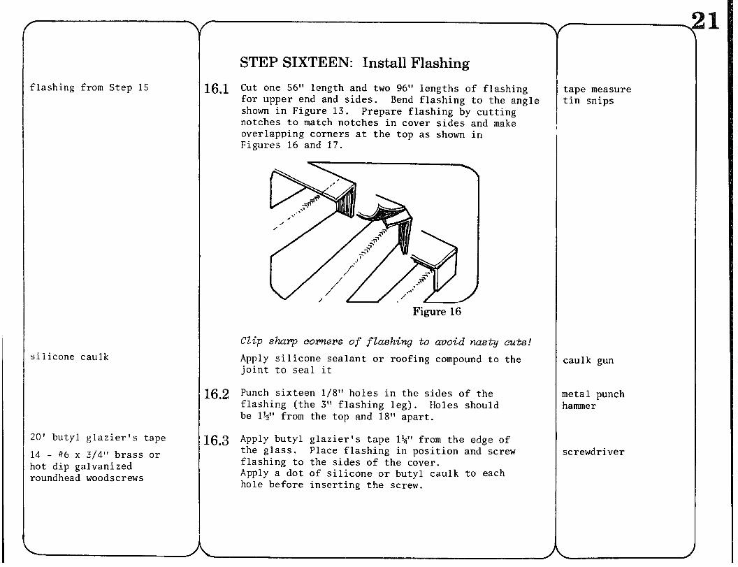
16.1 Cut one 56” length and two 96” lengths of flashing for upper end and sides. Bend flashing to the angle shown in Figure 13. Prepare flashing by cutting notches to match notches in cover sides and make overlapping corners at the top as shown in Figures 16 and 17.
Figure 16
clip sharp corners of flashing to avoid nasty cuts! Apply silicone sealant or roofing compound to the joint to seal it
16.2 Punch sixteen l/8” holes in the sides of the flashing (the 3” flashing leg). Holes should be l?’ from the top and 18” apart.
16.3 Apply butyl glazier’s tape 1%” from the edge of the glass. Place flashing in position and screw flashing to the sides of the cover. Apply a dot of silicone or butyl caulk to each hole before inserting the screw.
tape measure tin snips
caulk gun
metal punch hammer
screwdriver
8 - l;i” x 1%” hot dip galvanized lag screws
:en I;i”i. d. x q’o .d . washers
)utyl or silicone caulk
r -T
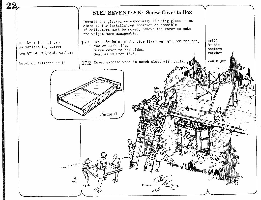
STEP SEVENTEEN: Screw Cover to Box
Install the glazing -- especially if using glass -- as close to the installation location as possible. If collectors must be moved, remove the cover to make ,the weight more manageable.
17.1 Drill &” hole in the side flashing l+ii from the top, two on each side. Screw cover to box sides. Seal as in Step 16.3.
drill 1,” bit sockets ratchet / I
17.2 Cover exposed wood in notch slots with caulk.
.&cs+-==- h
This list is for one collector. aterials Double the quantities as necessary for two collectors.
f Lumber:
3 8’ 2”x6” #2 fir 1 4’x8’x3/8” CDX plywood 32’ ll’x2” clear fir (two 10’; one 12’) 30’ l”x3” clear fir (three 10’ pieces) 12’ l”~4~’ fir (need not be clear fir,
but must be knot-free)
Building supplies:
1 tube silicone caulk 1 quart marine resin glue, plastic
(recommend: “Wi lholdl’) 1 tube Builder’s Adhesive 32 ft2 R-11 fiberglass insulation, foilback,
24” wide (if only 16” width is available, cut to width with utility knife)
25’ 2”x3” L-shaped flashing (or get 5” flat and bend it yourself)
2 8’ sections, galvanized steel roofing, corrugated, thinnest gauge available
1 pint flat black high quality, high tempera- ture enamel paint (recommend: Sherwin-Williams wrought iron flat black or Rustoleumt,)
+ gallon exterior latex paint (or enamel primer, if time permits)
Miscellaneous and specialty supplies
1 quart vinegar or galvanized metal prepara- tion or weak solution of muriatic acid
2 sheets 48”x48” double strength glass (option: 48”x98” Lascolitetm or Filontm fiber-
glass glazing material) 8’1inear Teflon film, 1 mil, 48” wide (at least) 1 roll %” butyl glazier’s tape 1 roll cellophane tape
Hardware supplies: \
$ lb. 4d finish nails k lb. 66 nails, galvanized 14 #10x2$” flathead woodscrews 12 #6x3/4” flathead woodscrews 10 #8x1%” flathead woodscrews 6 #8x1+” galvanized roundhead woodscrews
10 #6x&” sheet metal screws 14 #6x3/4” brass or hot dip galvanized
roundhead woodscrews 4 brass screws sized to replace screws
that come with mirror clips
1 roll wire 22 gauge stainless steel or 16 gauge copper or galvanized
4 plastic mirror clips 1 box 3/8” heavy duty staples 1 box g/16” heavy duty staples
30” fiber strand tape
Plumbing supplies:
3 20’ sections $” rigid copper tu’bing Type M
10’ 3/4” rigid copper tubing, Type M 14 3/4”~3/4”x+” copper tees
(15 if used in a bank) 3/4”-to-L+
(: if to be used in-a bank) copper elbow
2 3/4” copper sweat-to-3/4” male NPT adapter
2 &I’ copper coup 1 ings 2 3/4” copper caps 1 3/4” bronze globe valve 1 hose adapter small can of flux, not acid
(or use l’solder in flux”) 1 roll SO-SO solder, not acid core (+ lb.) (this is more than enough for 2 col-
lectors, usually enough for a whole installation)
small roll Teflon tape pipe thread sealer
The collector we’ve just shown you how to build has been the subject of much development and, recently, of a lot of study. It is being tested in the U.S. Department of Energy collector test program. It is also a component in the thermosiphon system whose performance is being studied as part of our water heater research project funded by the National Center for AppmFriate Technology. If the collector is rated favorably by DOE, the design may qualify for loans, credits, and other good treatment products of the solar industry receive. Our aim, though, is not to link do-it-yourself technology to a few standard designs, but to offer a proven example of it that gives a quality alternative to buying a commercial system.
Keep in mind that the collector we’ve just shown you is only one design-- though a proven one. It can be used as a basis for a solution to water heating that uses materials you have available or that meets a specific design requirement you have. There are many opportunities for improvement in details, and for substitution of component materials in the basic flat plate collector. A few ideas will be discussed here to show yox what can be done.
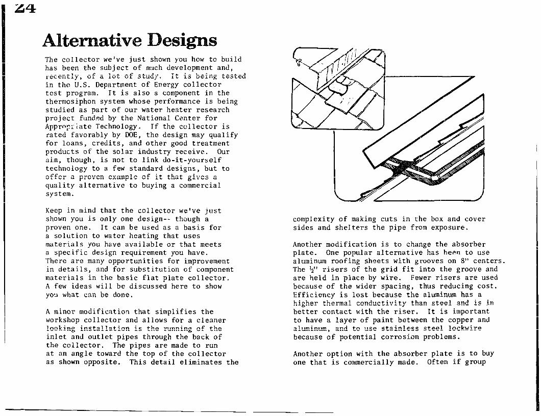
A minor modification that simplifies the workshop collector and allows for a cleaner looking installation is the running of the inlet and outlet pipes through the back of the collector. The pipes are made to run at an angle toward the top of the collector as shown opposite. This detail eliminates the
complexity of making cuts in the box and cover sides and shelters the pipe from exposure.
Another modification is to change the absorber plate. One popular alternative has been to use aluminum roofing sheets with grooves on 8” centers. The G” risers of the grid fit into the groove and are held in place by wire. Fewer risers are used because of the wider spacing, thus reducing cost. Efficiency is lost because the aluminum has a higher thermal conductivity than steel and is in better contact with the riser, It is important to have a layer of paint between the copper and aluminum, and to use stainless steel lockwire because of potential corrosion problems.
Another option with the absorber plate is to buy one that is commercially malde. Often if group
orders are made they can be bought for a price equal to or cheaper than the cost of the do-it- yourself. However, if you are building a thermosiphon system you will have to find out if the plate you are buying will work, because most commercial absorbers are designed for pumped systems that can have higher flow resistance. Another thing to consider is that the absorber plate size may require a modified box size.
The glazing is another component that can be experimented with. Although the double-strength glass used in the collector described is widely available, highly transparent and relatively cheap, it also has a tendency to break-- which is a real problem in areas subject to hail or other high impact fallout. Tempered glass is much tougher and can often be bought cheaper as factory seconds than regular double-strength glass, and work fine for solar collectors. These sheets come in standard sizes-- generally 28x76”, 34x76” and 46x76”) and cannot be cut, so a collector using them will have to be made to fit.
It is often suggested that sealed, double-pane insulating glass windows be used to give instant double glazing to the collector. Two things are likely to happen. The first is that the seal is likely to leak and allow water in between the glass panes, causing fogging. (Drill ing vent holes in the edge might solve this.) The second is that the inner pane of glass may shatter due to high thermal expansion obstructed by the edge seal.
The other glazing option is to use a solar-grade fiberglass. These can be lighter and cheaper than glass and are unbreakable, though their transmissivity tends to be lower than glass and
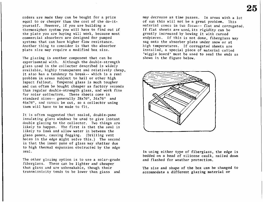
may decrease as time passes. In areas with a lot of sun this wili not be a great problem. This mat-m-ial _..---A --A comes in a..-- LWU fOlrnS-- fiat and corrugated ~ If flat sheets are used,its rigidity can be greatly increased by bowing it with curved endpieces. If this is not done, fiberglass may sag onto the absorber plate under snow or at high temperatures. If corrugated sheets are installed, a special piece of material called ‘wiggle board I must be used to seal the ends as shown in the figure below.
In using either type of fiberglass, the edge is bedded on a bead of silicone caulk, nailed down and flashed for weather protection.
The size and shape of the box can be changed to accommodate a different glazing material or
absorber plate or to meet a special situation as shown on page 43. When changing the box size, care must be taken not to waste lumber. For instance, if a 76” length is used to take advantage of low-cost tempered glass seconds, the sides can be cut out of one 14’ 2x6 with less waste than if cut from two 8’ 2x6s. Generally speaking, if the same area is contained in smaller boxes, more material will be used. So build the largest size you can, while still keeping a manageable size for handling.
The collector design in the instructions uses 2x6 sides to take advantage of self-insulation and to make a collector that will support its own weight. It is possible to make the whole collector from plywood-- if carefully planned, a smaller size collector box may be made from one sheet of plywood. Strength and durability will only be obtained if reinforcing nailer strips and glue are used. (Plywood edge grain does not offer much of a hold to nails or screws.) Because the absorber plate and glass are heavy, the collector may have to be supported by the mounting stand, which may reduce savings obtained by using less wood in the collector.
The collector box does not have to be built with wood, though that is usually the material that is easiest for most people to work with. Sheet metal can also be used if the skills and tools are available. Another approach would be to use standard steel framing pieces to form the sides of the box, allowing the box to be bolted together. The major design problems here are to be sure the absorber plate and pipes do not touch the box, and to insulate the sides as well as the back of the box. The most feasible insulating material is polyurethane foam. Care must also be taken to properly prime and paint the metal to prevent rust.
Rigid insulation board can be used, but it is more expensive than fiberglass batts. One- inch polyurethane foil-back board is possibly the best material available at this time. As with fiberglass, be sure to put the foil up. If unfoiled board is used, put on a layer of aluminum foil. Styrofoamt, has proven itself to be incapable of withstanding temperatures higher than 200° F, which occur when the collector is stagnated (not cooled by water flow). This may occur if the collector isn’t covered when it’s not working. Never put loose fill insulation in a collector; it will wander all over the collector and is likely to absorb moisture.
This book focuses on flat plate collectors with parallel-tube fluid channels. There are many other designs available, from flat plate collectors with serpentine fluid channels to batch-type heaters such as bread boxes and roof ponds. Some of these are referenced in the “Further Reading” section.
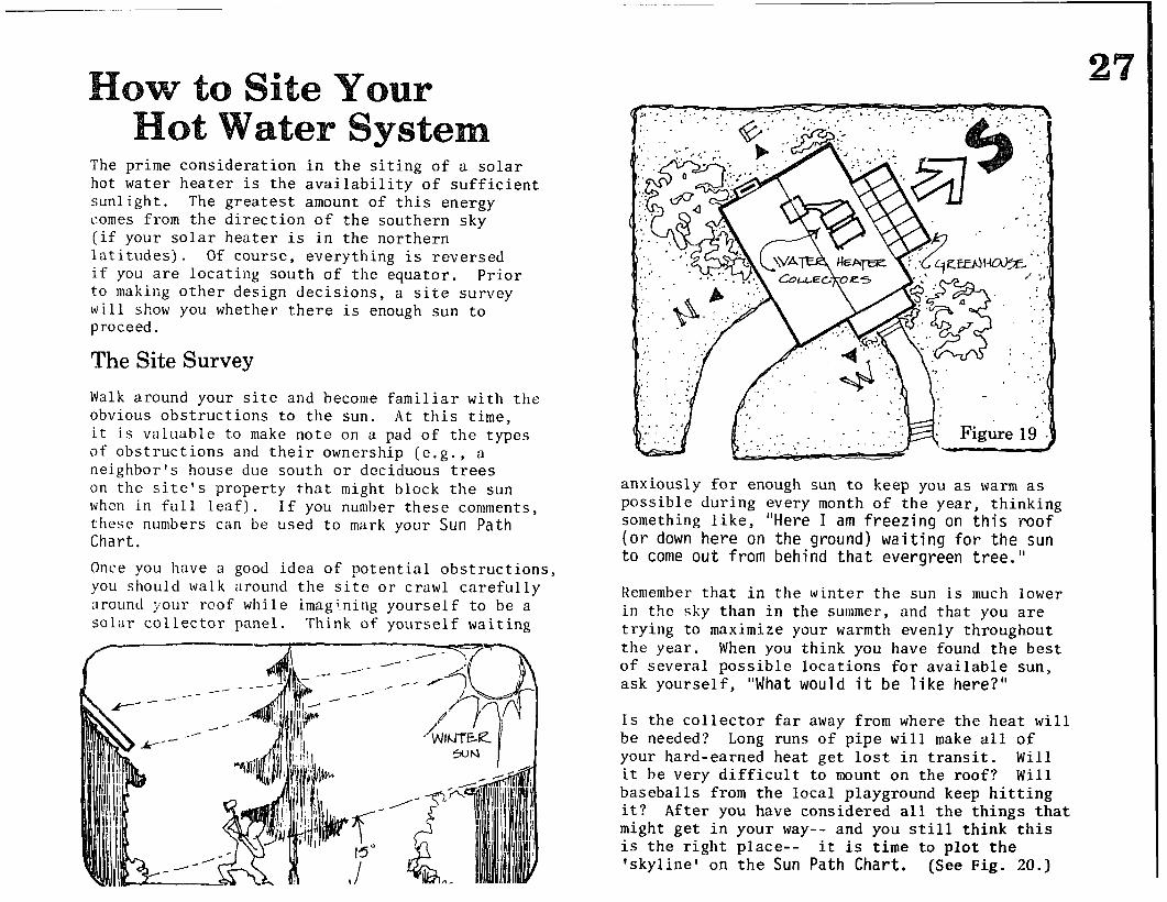
The prime consideration in the siting of a solar hot water heater is the availability of sufficient sun1 ight. The greatest amount of this energy comes from the direction of the southern sky (if your s o ar heater is in the northern 1 latitudes). Of course, everything is reversed if you are locatil?g south of the equator. Prior to making other design decisions, a site survey will show you whether there is enough sun to proceed.
The Site Survey
Walk around your site and become familiar with the obvious obstructions to the sun. At this time, it is valuable to make note on a pad of the types of obstructions and their ownership (e.g., a neighbor’s house due south or deciduous trees on the site’s property that might block the sun when in full leaf). If you number these comments, these numbers can be used to mark your Sun Path Chart.
Once you have a good idea of potential obstructions, you should walk around the site or crawl carefully around your roof while imag’ning yourself to be a solar collector panel. Think of yourself waiting
anxiously for enough sun to keep you as warm as possible during every month of the year, thinking something like, "Here I am freezing on this roof (or down here on the ground) waiting for the sun to come out from behind that evergreen tree."
Remember that in the winter the sun is much lower in t?le sky than in the summer, and that you are trying to maximize your warmth evenly throughout the year. When you think you have found the best of several possible locations for available sun, ask yourself, "What would it be like here?"
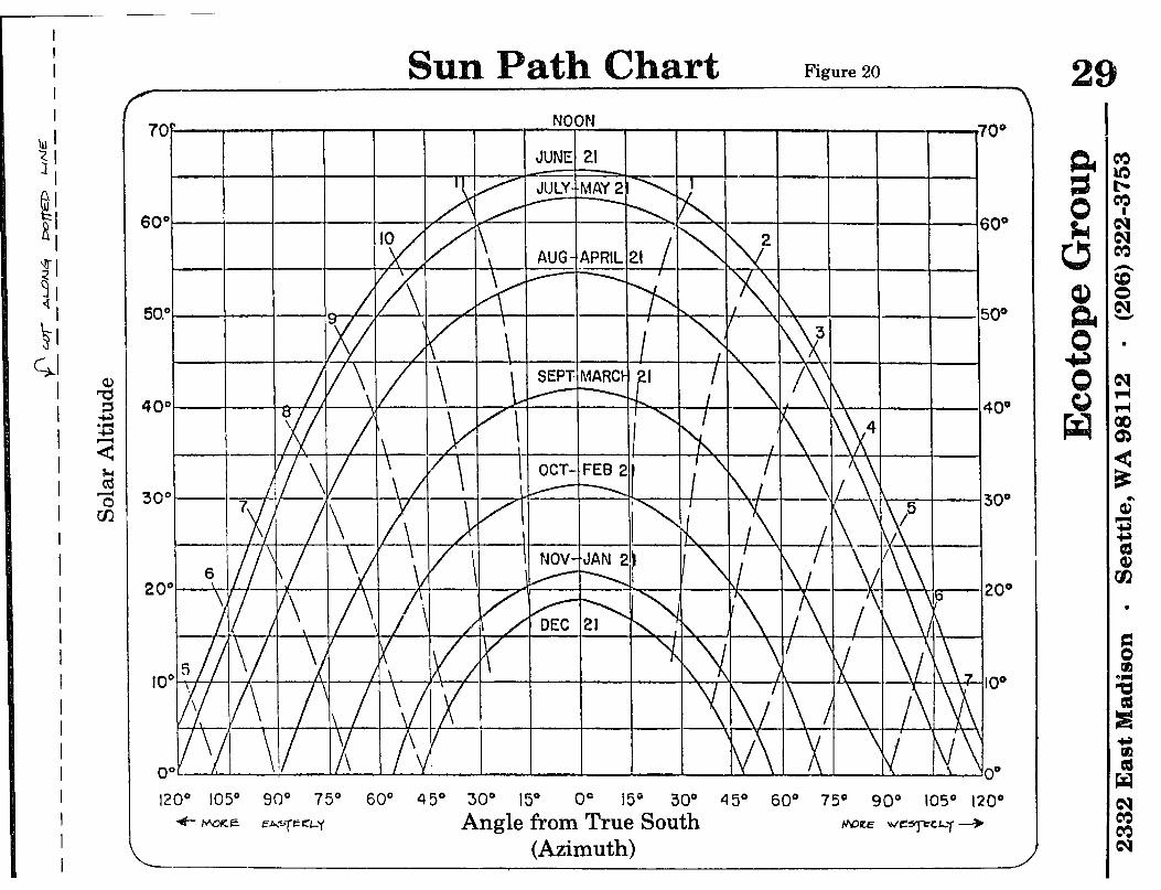
Is the collector far away from where the heat will be needed? Long runs of pipe will make all of your hard-earned heat get lost in transit. Will it be very difficult to mount on the roof? Will baseballs from the local playground keep hitting it? After you have considered all the things that might get in your way-- and you still think this is the right place-- it is time to plot the ‘skyline’ on the Sun Path Chart. (See Fig. 20.)
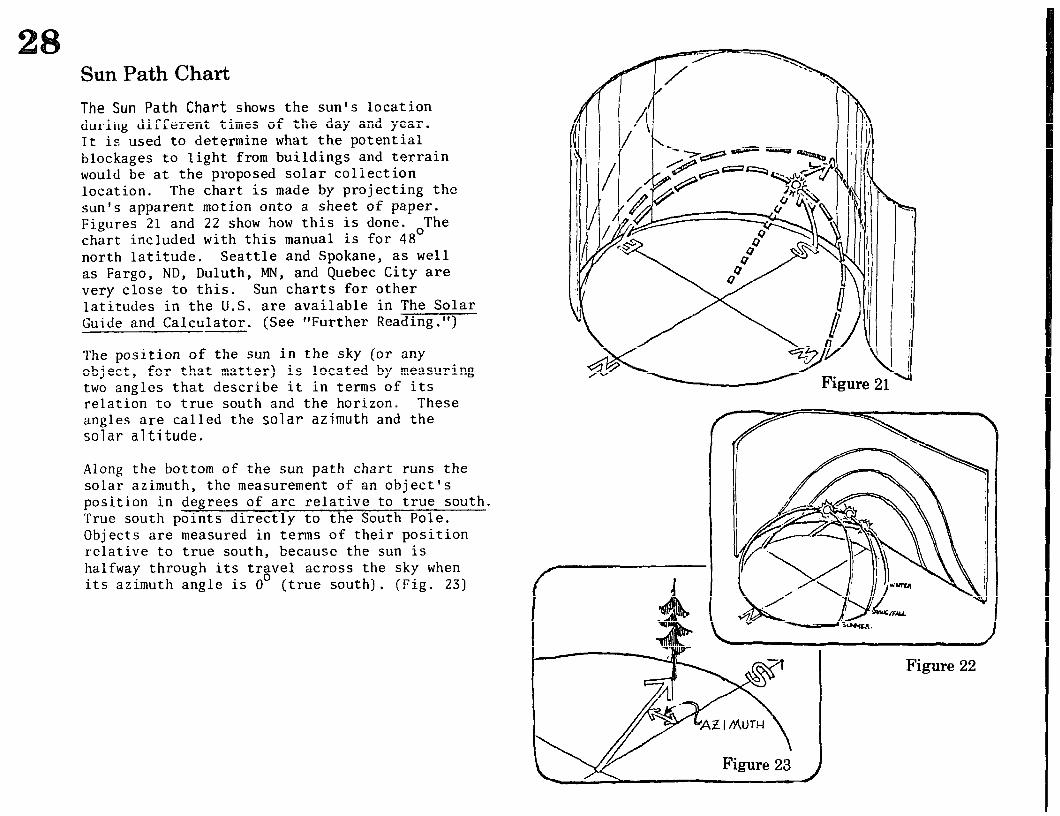
Sun Path Chart
The Sun Path Chart shows the sun’s location during different times of the day and year. It is used to determine what the potential blockages to light from buildings and terrain would be at the proposed solar collection location. The chart is made by projecting the sun’s apparent motion onto a sheet of paper. Figures 21 and 22 show how this is done. The chart included with this manual is for 48’ north latitude. Seattle and Spokane, as well as Fargo, ND, Duluth, MN, and Quebec City are very close to this. Sun charts for other latitudes in the U.S. are available in The Solar Guide and Calculator. (See “Further Reading. “)
The position of the sun in the sky (or any object, for that matter) is located by measuring two angles that describe it in terms of its relation to true south and the horizon. These angles are called the solar azimuth and the solar altitude.
Along the bottom of the sun path chart runs the solar azimuth, the measurement of an object’s position in degrees of arc relative to true south. True south points directly to the South Pole. Objects are-measured in terms of their position relative to true south, because the sun is halfway through its trgvel across the sky when its azimuth angle is 0 (true south). (Pig. 23)
Figure 22
at Figure 20
bW"
AUG - APRIL 21
20°
, IO0
\ !/ I/\ I I O0 1200 1054 go0 75O 60° 45O 30° 15” 0’ 15” 30’ 45’ 60’ 75’ 90” 1050 120°
4- wcnzt EAzTE cl-‘f Angle from True South tfaetz Wr3J-cC~7 +
(Azimuth)
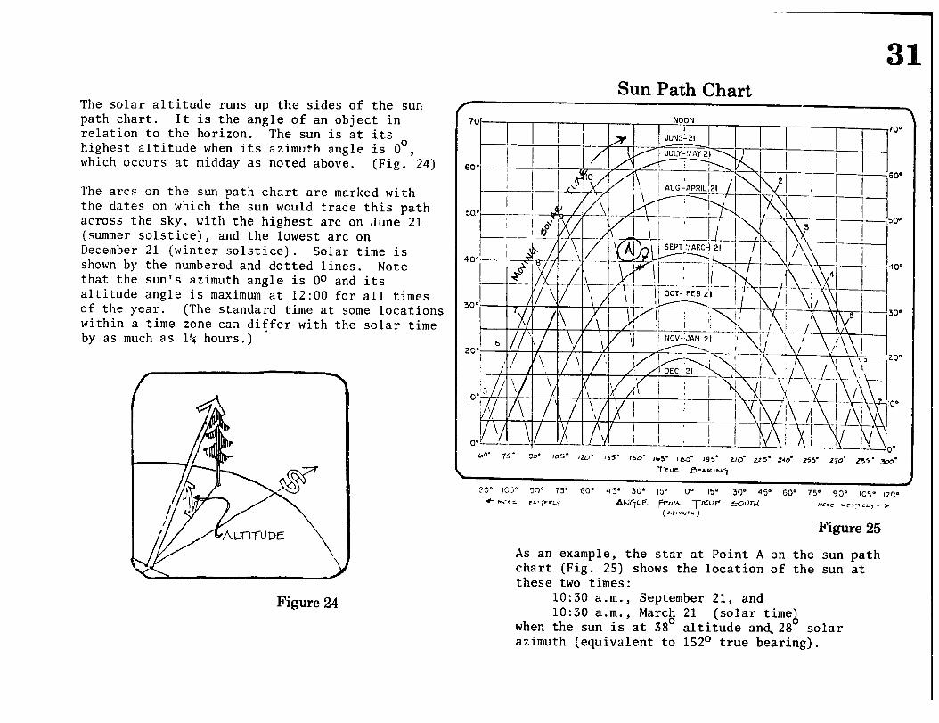
Sun Path Chart The solar altitude runs up the sides of the sun path chart. It is the angle of an object in relation to the horizon. The sun is at its highest altitude when its azimuth angle is O”, which occurs at midday as noted above. (Fig. 24)
The arcs on the sun path chart are marked with the dates on which the sun would trace this path across the sky, with the highest arc on June 21 (summer solstice), and the lowest arc on December 21 (winter solstice). Solar time is shown by the numbered and dotted lines. Note that the sun’s azimuth angle is Oo and its altitude angle is maximum at 12:00 for all times of the year. (The standard time at some locations within a time zone can differ with the solar time by as much as l& hours.) ’
Figure 24
tv NOON I
II I
700
i-l
R ” /L-i -kf24&B
] i- , -71 1 i--r
-’ ; ;j-l / ‘500
i_ I 1
,-
31
LO’ jq- qg. 1
105’ IW’ 135’ 150’ vw5- ,,xJ- 195. Zld U5. 240. .?55’ Z?O’ ,?n5- m’
123’ IUJ ‘,I,- Is- D”- ‘I>- .xJ- 15’ 0’ 15’ 30’ 4Y 60’ 75’ 9P IC5’ IZC. f t+.-<i: .=a. :PcLy ANC,E PIA TKUE eaW
(AZ!W.d) wrC .C’;vEL, - ,
Figure 25
As an example, the star at Point A on the sun path chart (Fig. 25) shows the location of the sun at these two times:
lo:30 a.m., September 21, and lo:30 a.m., March 21 (solar time
when the sun is at 38’ altitude and.28 A solar azimuth (equivalent to 152O true bearing).
The skyline that you see when standing at the collector site is plotted on the sun path chart so that you can determine which objects will block the sun and when they will. To plot the skyline, you must locate each object in terms of its azimuth and altitude angles. We will describe here how to plot these two angles, and give an example of how a tree would be plotted on the chart. (See figure 31.)
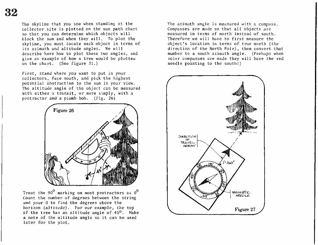
First, stand where you want to put in your collectors, face south, and pick the highest potential obstruction to the sun in your view. The altitude angle of the object can be measured with either a transit, or more simply, with a protractor and a plumb bob. (Fig. 26)
Treat the 90’ marking on most protractors as 0’ Count the number of degrees between the string and your 0 to find the degrees above the horizon (altitude). For our example, the top of the tree has an altitude angle of 45O. Make a note of the altitude angle so it can be used later for the plot.
The azimuth angle is measured with a compass. Compasses are made so that all objects are measured in terms of north instead of south. Therefore we will h&ve to first measure the object’s location ill terms of true north (the direction of the North Pole), then convert that number to a south azimuth angle. (Perhaps when solar compasses are made they will have the red needle pointing to the south!)
Figure 27 ,
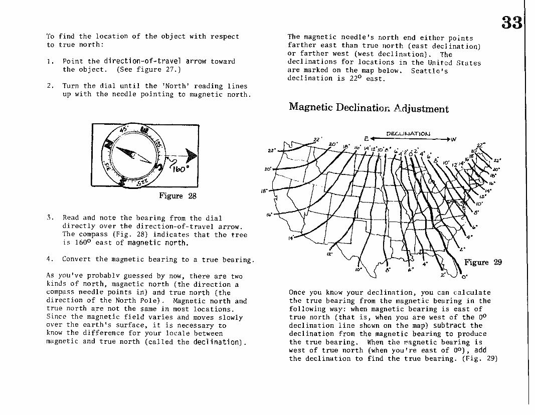
To find the location of the object with respect to true north:
1. Point the direction-of-travel arrow toward the object. (See figure 27.)
The magnetic needle’s north end either points farther east than true north (east deck ination) or farther west (west declination). The declinations for locations in the United States are marked on the map below. Seattle’s declination is 22O east.
2. Turn the dial until the ‘North’ reading lines up with the needle pointing to magnetic north.
Magnetic Declinath Adjustment
Figure 28
3. Read and note the bearing from the dial directly over the direction-of-travel arrow. The compass (Fig. 28) indicates that the tree is 160° east of magnetic north.
4. Convert the magnetic bearing to a true bearing.
As you've probablv guessed by now, there are two kinds of north, magnetic north (the direction a compass needle points in) and true north (the direction of the North Pole). Magnetic north and true north are not the same in most locations. Since the magnetic field varies and moves slowly over the earth’s surface, it is necessary to know the difference for your locale between magnetic and true north (called the declination).
DELLINATION -3 ’ .W
Once you know your declination, you can calculate the true bearing from the magnetic bearing in the following way: when magnetic bearing is east of true north (that is, when you are west of the Oo declination line shown on the map) subtract the declination from the magnetic bearing to produce the true bearing. When the magnetic bearing is west of true north (when you’re east of Oo), add the declination to find the true bearing. (Fig. 29)
For our example, since Seattle is 22’ east, the true bearing is:
160” - 22’ = 138’
( de~~~~~:fon) (b~~~~g)
The tree is therefore 138’ east of true north. To find the azimuth, simply subtract 180” from the true bearing.
138O - 180” = -42”
( t~e~~fn~hl C COIl~~l~OIlj (eas;t;fj
bearing
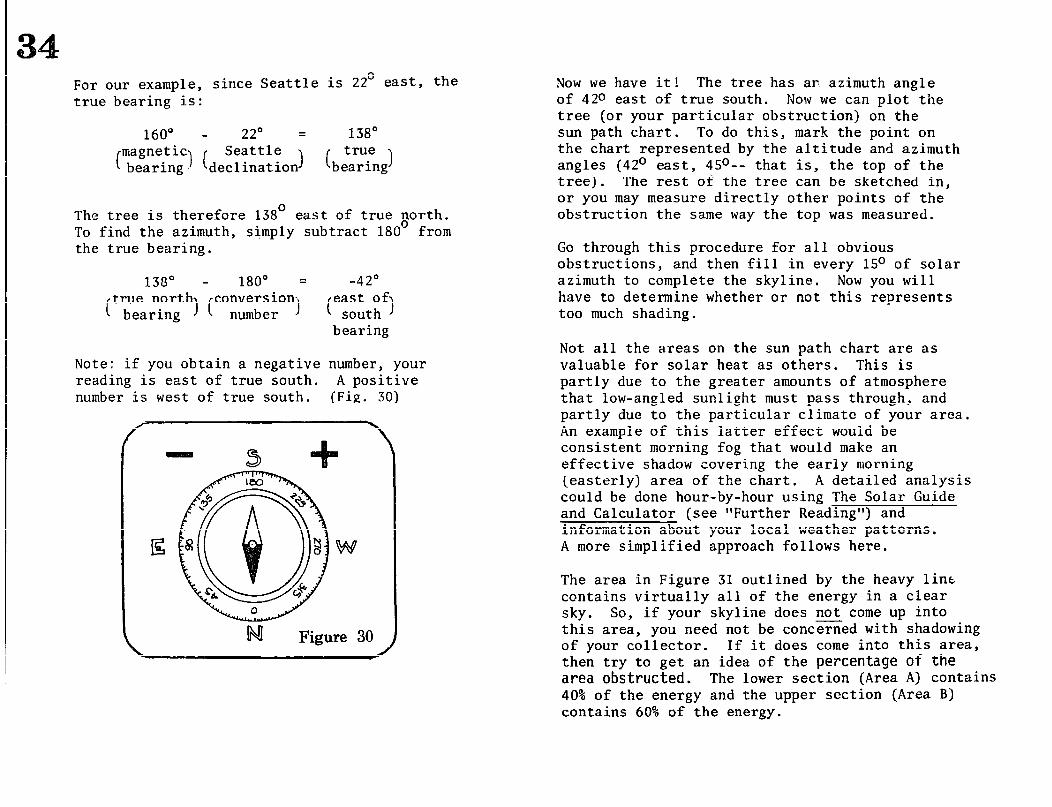
Note: if you obtain a negative number, your reading is east of true south. A positive number is west of true south. (Fig. 30)
iNI Figure 30
Now we have it! The tree has ar azimuth angle of 420 east of true south. Now we can plot the tree (or your particular obstruction) on the sun path chart. To do this, mark the point on the chart represented by the altitude and azimuth angles (42O east, 4S”-- that is, the top of the tree). The rest of the tree can be sketched in, or you may measure directly other points of the obstruction the same way the top was measured.
Go through this procedure for all obvious obstructions, and then fill in every lS” of solar azimuth to complete the skyline. Now you will have to determine whether or not this represents too much shading.
Not all the areas on the sun path chart are as valuable for solar heat as others. This is partly due to the greater amounts of atmosphere that low-angled sunlight must pass through, and partly due to the particular climate of your area. An example of this latter effect would be consistent morning fog that would make an effective shadow covering the early morning (easterly) area of the chart. A detailed analysis could be done hour-by-hour using The Solar Guide and Calculator (see “Further Reading”) and information about your local weather patterns. A more simplified approach follows here.
The area in Figure 31 outlined by the heavy line contains virtually all of the energy in a clear sky. So, if your skyline does not come up into this area, you need not be concerned with shadowing of your collector. If it does come into this area, then try to get an idea of the percentage of the area obstructed. The lower section (Area A) contains 40% of the energy and the upper section (Area B) contains 60% of the energy.
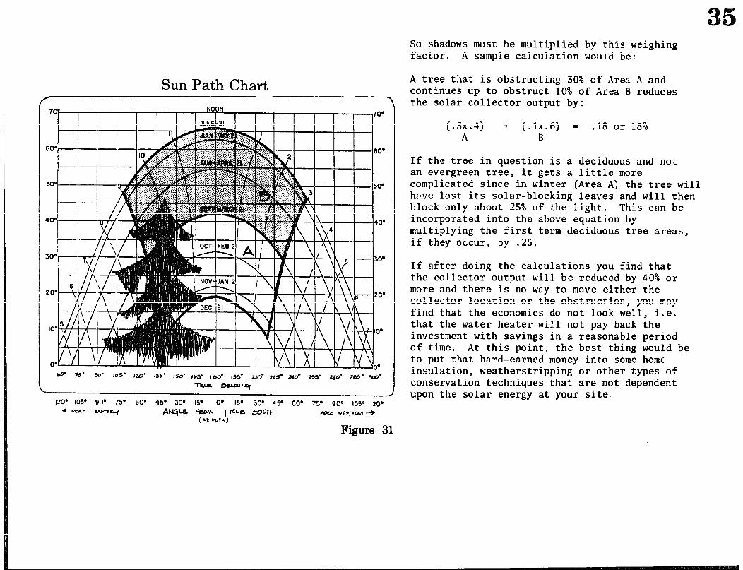
Sun Path Chart
60’ 60.
xl’ 5v
400 408
300 30’
20’ 20’
IO’
So shadows must be multiplied by this weighing factor. A sample calculation would be:
A tree that is obstructing 30% of Area A and continues up to obstruct 10% of Area B reduces the solar collector output by:
(.3x.4) + (.1x.6) = .18 or 18% A B
If the tree in question is a deciduous and not an evergreen tree, it gets a little more complicated since in winter (Area A) the tree will have lost its solar-blocking leaves and will then block only about 25% of the light. This can be incorporated into the above equation by multiplying the first term deciduous tree areas, if they occur, by .25.
If after doing the calculations you find that the collector output will be reduced by 40% or more and there is no way to move either the collector location or the obstruction, you may find that the economics do not look well, i.e. that the water heater will not pay back the investment with savings in a reasonable period of time. At this point, the best thing would be to put that hard-earned money into some home insulation, weatherstripping or other types of conservation techniques that are not dependent upon the solar energy at your site,
Figure 31
Qrientation of the Collector
Since hot water is used fairly evenly throughout the year, we will want to pick a collector tilt that will give tne best year-round performance. This is approximately equal to the latitude, in Seattle roughly 45O-48O. This assumes that no reflector is incorporated into the design, as with this workshop.
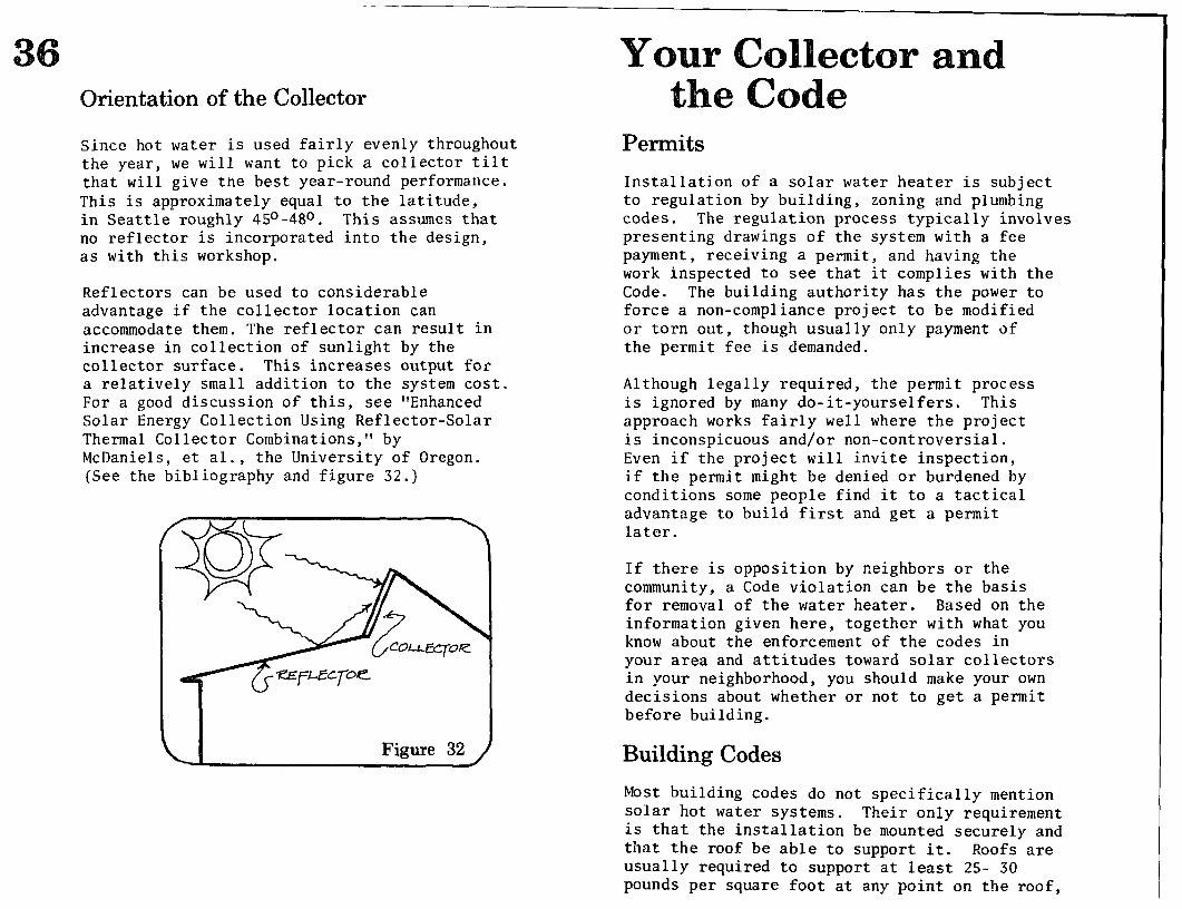
Reflectors can be used to considerable advantage if the collector location can accommodate them. The reflector can result in increase in collection of sunlight by the collector surface. This increases output for a relatively small addition to the system cost. For a good discussion of this, see “Enhanced Solar Energy Collection Using Reflector-Solar Thermal Collector Combinations,” by McDaniels, et al., the University of Oregon. (See the bibliography and figure 32.)
Figure 32
Permits
Installation of a solar water heater is subject to regulation by building, zoning and plumbing codes. The regulation process typically involves presenting drawings of the system with a fee payment, receiving a permit, and having the work inspected to see that it complies with the Code. The building authority has the power to force a non-compliance project to be modified or torn out, though usually only payment of the permit fee is demanded.
Although legally required, the permit process is ignored by many do-it-yourselfers. This approach works fairly well where the project is inconspicuous and/or non-controversial. Even if the project will invite inspection, if the permit might be denied or burdened by conditions some people find it to a tactical advantage to build first and get a permit later.
If there is opposition by neighbors or the community, a Code violation can be the basis for removal of the water heater. Based on the information given here, together with what you know about the enforcement of the codes in your area and attitudes toward solar collectors in your neighborhood, you should make your own decisions about whether or not to get a permit before building.
Building Codes
Most building codes do not specifically mention solar hot water systems. Their only requirement is that the installation be mounted securely and that the roof be able to support it. Roofs are usually required to support at least 25- 30 pounds per square foot at any point on the roof,
but some points will be able to support considerably more. The panels in this manual weigh about 10 pounds per square foot when full, excluding any support structure. The storage tank (if 60 gallons) when full weighs about 600 pounds without its frame. Building inspectors may not be too concerned about this issue, but for safety’s sake, you should be. Read the “Installation” section thoroughly, and plan your system so that it will distribute t.he load stress on your roof safely.
Zoning Ordinances
Zoning ordinances are of concern because they may contain minimum clearance requirements between structures and property lines. For example, if the clearance requirement for a side yard is 10 feet, and an installation is made closer to the property 1 ines , it is in violation. In one recent case this was the grounds for forcing the collectors to be removed when a neighbor obiected to the glare. (Solar Age 3 (3) Marih, 19785 For any ground installation near a property line, the requirements for the site concerned should be checked. This is usually administered by the Building Department as part of the permit process.
Plumbing Codes and Proposed Collector Criteria
Plumbing codes and proposed regulations dealing specifically with solar systems have a lot of bearing on the installation of solar hot water heaters. Technically, any change in the water supply in a house requires a permit in most areas. A major point of concern is that poisonous antifreeze not contaminate water that comes out of household outlets. (See the manual section on “Freeze Prorection.“) The plumbing code is administered by the Building Department in most places and operates in the same way.
i ePatio
Permanently installing the collectors you have built is the most challenging aspect of putting a working system together. The major considerations are collector and tank location, safe and durable mounting and weatherproofing details to protect the system and your building, integrating the system into your regular water supply, and protection of the system from freezing.
Each situation is very different in its requirements, so it is not possible to give a specific plan, Instead, we have given a good deal of information on these issues to provide you with the background necessary to install properly in your case. It is highly advisable to read this entire section and think about the system as a whole before you build your collectors, since you may wish to modify the collector design. It may also be helpful to turn back to the full system schematic on page 46 for reference as you read.
The first step will be to decide where to put the tank and the collectors. This decision is affected by solar exposure, structural requirements, and whether you want to build a thermosiphon or a pumped system. Then you will have to plan how to permanently install these components to withstand wind, rain, snow and gravity. Part of this process will be planning where pipes will run- both between the storage tank and the collectors and from the water supply to the point of hooking with the hot water system. Finally, freeze protection should be considered at this point because it may
influence your basic choice on whether or not to use a pumped (or active) system, and the tank position requirements in a thermosiphon s:stem.
A frequent question is whether or not the collectors should be installed on a stand that allows the tilt angle to be changed to follow the sun’s changing altitude. The gain in collector output if the angle is changed four times a year can be as high as 10% to 20%. However, the capability is difficult to build into the system.
The first problem comes from trying to develop a durable, leakproof plumbing connection that can flex to accommodate the change of position. A high-temperature silicone hose is probably the best solution. The second problem lies in building a mounting stand that allows the collector to move, but fastens it securely enough to withstand wind.
Wood used in collector and tank support stands must be protected against the elements. Especially if the stand is attached to the roof it is wise to build it with pressure treated wood. At the very least it must be well finished and maintained.
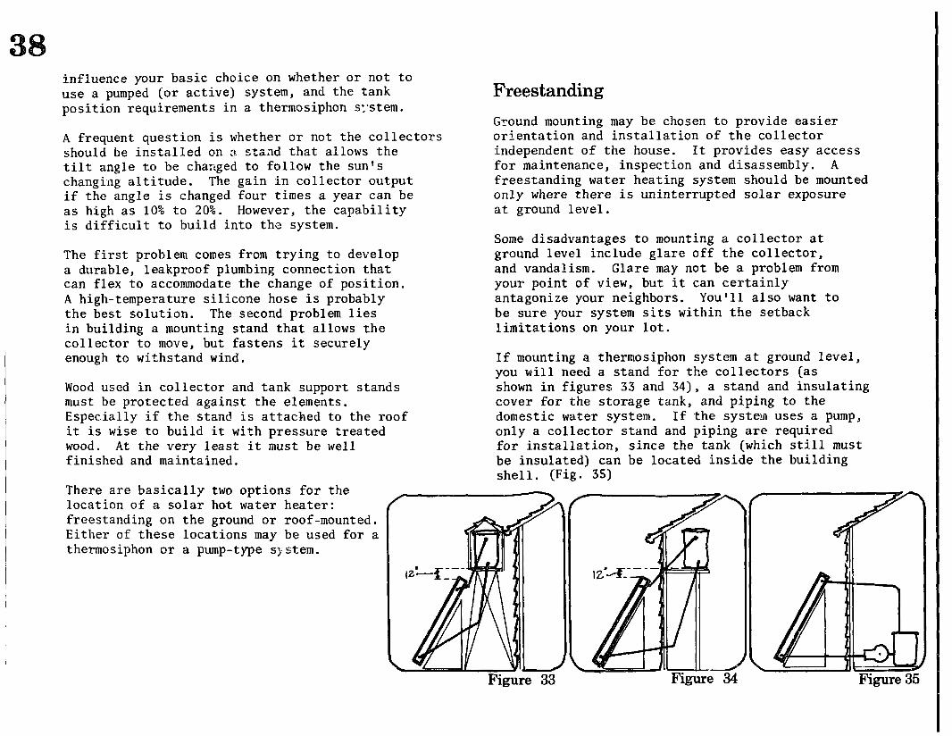
There are basically two options for the location of a solar hot water heater: freestanding on the ground or roof-mounted. Either of these locations may be used for a thermosiphon or a pump-type system.
Freestanding
Ground mounting may be chosen to provide easier orientation and installation of the collector independent of the house. It provides easy access for maintenance, inspection and disassembly. A freestanding water heating system should be mounted only where there is uninterrupted solar exposure at ground level.
Some disadvantages to mounting a collector at ground level include glare off the collector, and vandalism. Glare may not be a problem from your point of view, but it can certainly antagonize your neighbors. You’ll also want to be sure your system sits within the setback 1 imitations on your lot.
If mounting a thermosiphon system at ground level, you will need a stand for the collectors (as shown in figures 33 and 34), a stand and insulating cover for the storage tank, and piping to the domestic water system. If .the system uses a pump, only a collector stand and piping are required for installation, since the tank (which still must be insulated) can be located inside the building shell. (Fig. 35)
Figure 33
Rooftop Mounting The most popular installation site is on the house rooftop because this is often the only site with decent solar exposure. Such mounting has the advantages of being out of sight, thereby reducing possible glare to neighbors. It is also out of reach of children, vandals, and ornery dogs.
The drawback to rooftop mounting is that the collectors and other components have to be lifted and attached to the roof and supported by it. Once the system is installed on the roof, it is harder to maintain and service because access is more difficult.
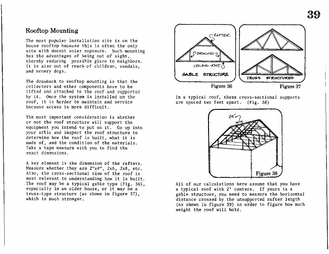
The most important consideration is whether or not the roof structure will support the equipment you intend to put on it. Go up into your attic and inspect the roof structure to determine how the roof is built, what it is made of, and the condition of the materials. Take a tape measure with you to find the exact dimensions.
A key element is the dimension of the rafters. Measure whether they are 2”x4”, 2x6, 2x8, etc. Also, the cross-sectional view of the roof is most relevant to understanding how it is built. The roof may be a typical gable type (Fig, 36), especially in an older house, or it may be a truss-type structure (as shown in figure 37), which is much stronger.
Figure 36 Figure 37
In a typical roof, these cross-sectional supports are spaced two feet apart. (Fig. 38)
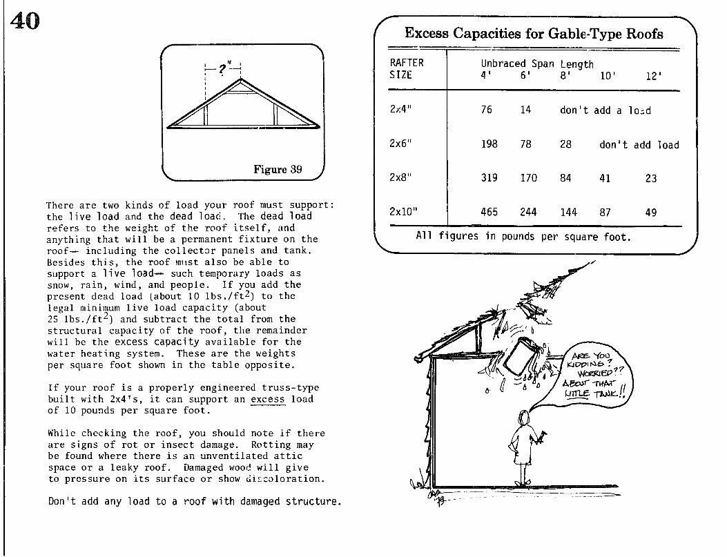
All of our calculations here assume that you have a typical roof with 2’ centers. If yours is a gable structure, you need to measure the horizontal distance crossed by the unsupported rafter length (as shown in figure 39) in order to figure how much weight the roof will hold.
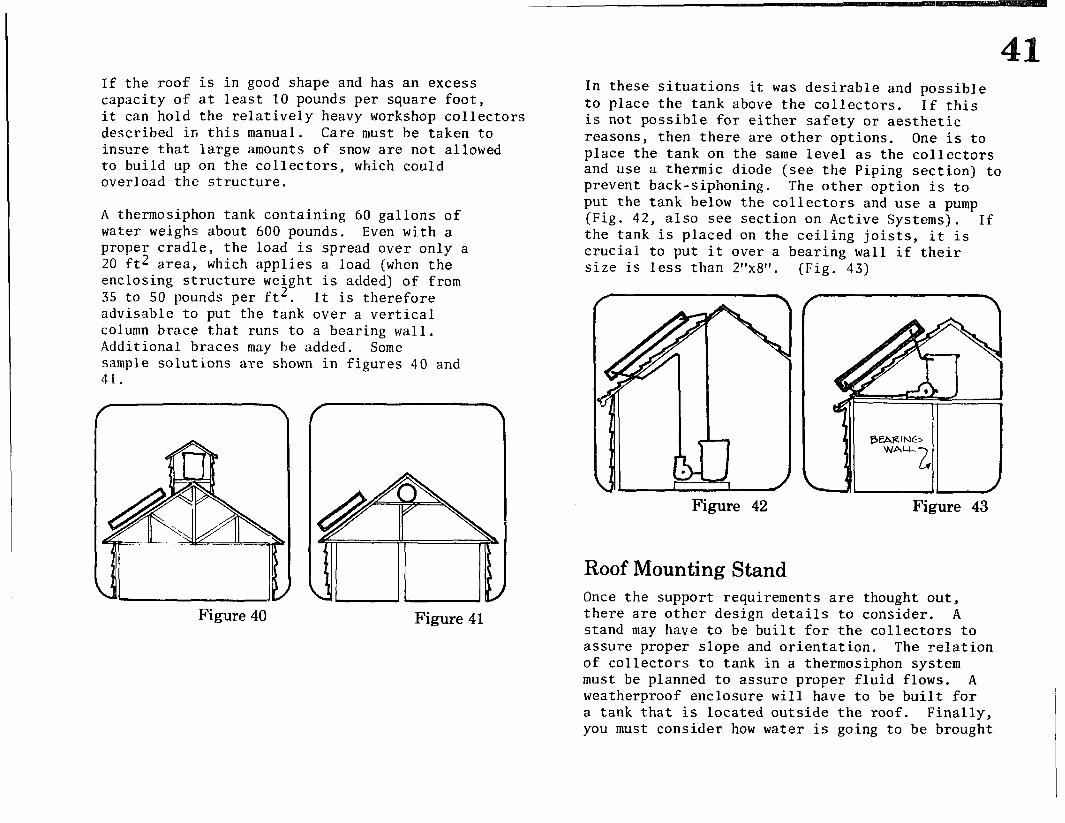
There are two kinds of load your roof must support: the live load and the dead load, The dead load refers to the weight of the roof itself, and anything that will be a permanent fixture on the roof- including the collector panels and tank. Besides this, the roof must also be able to support a live load- such temporary loads as snow, rain, wind, and people. If you add the present dead 1oa.d (about 10 lbs ./ft2) to the legal minimum live load capacity (about 25 lbs./ft2) and subtract the total from the structural capacity of the roof, tile remainder will be the excess capacity available for the water heating system. These are the weights per square foot shown in the table opposite.
If your roof is a properly engineered truss-type built with 2x4’s, it can support an excess load of 10 pounds per square foot.
While checking the roof, you should note if there are signs of rot or insect damage. Rotting may be found where there is an unventilated attic space or a leaky roof. Damaged wood will give to pressure on its surface or show discoloration.
Don't add any load to a roof with damaged structure.
-w Excess Capacities for Gable-Type Roofs
-- RAFTER Unbraced Span Length SIZE 4' 6' 8' 10’ 12'
2x4" 76 14 don't add a 1o;d
2x6” 198 78 28 don't add load
2x8” 319 170 84 41 23
2x10” 465 244 144 87 49
All figures in pounds per square foot.
a/'
/ A&&- -t’ktW r,
If the roof is in good shape and has an excess capacity of at least 10 pounds per square foot, it can hold the relatively heavy workshop collectors described in this manual. Care must be taken to insure that large amounts of snow are not allowed to build up on the collectors, which could overload the structure.
A thermosiphon tank containing 60 gallons of water weighs about 600 pounds. Even with a proper cradle, 20 ft2 area,
the load is spread over only a which applies a load (when the
enclosing structure weight is added) of from 35 to 50 pounds per ft2, It is therefore advisable to put the tank over a vertical column brace that runs to a bearing wall. Additional braces may be added, Some sample solutions are shown in figures 40 and
Figure 40 Figure 41
In these situations it was desirable and possible to place the tank above the collectors. If this is not possible for either safety or aesthetic reasons, then there are other options. One is to place the tank on the same level as the collectors and use a thermic diode (see the Piping section) to prevent back-siphoning. The other option is to put the tank below the collectors and use a pump (Fig. 42, also see section on Active Systems). If the tank is placed on the ceiling joists, it is crucial to put it over a bearing wall if their size is less than 2”x8”. (Fig. 43)
Figure 42 Figure 43
Roof Mounting Stand Once the support requirements are thought out, there are other design details to consider. A stand may have to be built for the collectors to assure proper slope and orientation. The relation of collectors to tank in a thermosiphon system must be planned to assure proper fluid flows. A weatherproof enclosure wili have to be built for a tank that is located outside the roof. Finally, you must consider how water is going to be brought
to the rooftop level, and where the pipes will run.
After a careful design is drawn out, the way in which it will be implemented must be planned. Stands for collectors and tank should be built before they are brought up onto the roof. Safety lines on heavy objects and extreme precaution are advisable.
An alternative to mounting the collectors above the roof is to build them into the roof. This is most easily done when bming a new house, but can also be incorporated into an existing roof with a bit more work. The insulation and absorber plates fit in between the rafters; the glazing is installed much like a skylight, with full flashing running under the shingles using liberal amounts of roof goo. Great care is required to prevent leaks.
Attaching Collectors to the Roof If the roof angle and orientation are good, the collectors can be mounted directly to the roof structure. They must be held slightly above the roof surface to avoid water damage to both roof and collectors. At the same time, they must be firmly attached to the rafters formi:lg the roof ’ s structure.
There are two basic ways to support and tie down the collectors. One is to raise the collectors with brackets that are bolted into the rafters. The collectors can either be attached directly to the brackets or can be bolted to horizontal runners that rest on the brackets. (Fig. 44)
Another way to tie down the collectors is to put nailers across the rafters and bolt the collectors to them. This is essentially the same thing as using runners on brackets. However, the nailer must be sloped to allow drainage of upstream water and also be sealed to prevent leakage in the roof and rot in the nailer. The procedure is to coat the place where the nailer is going to go with “plastic roof cement” (thick roof goo) , nail the nailer in place to the rafters, then coat the upstream edge with a thick coat of goo.
IMPORTANT Before planning the mounting system, refer tb the sktion on "Piping."
Tank Supports In cases where obtaining a proper angle requires that the collectors be tilted up off the roof, a sturdy mounting stand will have to be built. It should be constructed so that:
1) It supports the collectors at the proper angle.
2) It is sturdy and firmly tied to the rafters so that it will withstand strong winds,
3) It will not impede the flow of water off the roof or cause a leak.
If the roof slope faces south or if it is almost flat, the solution is fairly straightforward. It is somewhat difficult to give detailed instructions for a stand for every roof angle, because the variations in sites possible woJld make any instructions meaningless.
Figure 45
member in contact with the roof should be treated; structural members should be angled slightly so that water can drain from this ‘gutter.’
If the slope of the roof faces east or west, t.he difficulty of obtaining proper orientation, structural safety and architectural compatibility is far greater, and the difficulty increases with the slope of the roof. In these cases, a ground installation should be seriously considered. But if the roof is the only feasible place, the collectors can be modified to accommodate the situation, as shown in figure 46. The strategy here is to build thinner collectors that are placed on the slope of the roof in ranks spaced far apart enough to avoid shadowing. (See Fig. 473
Figure 46
Figure 45 shows a stand made from 2x4s that can do the job in many situations. In building any stand, we recommend that its structure and any part of the panels be lifted a few inches from the roof surface with a nailer to avoid water absorption and wood rot, plus water collection on the roof. The upstream side of any support
The collectors should be placed on whichever side of the roof receives the most sun. For i.nstance, in a region of frequent early-morning fogs the collectors should be placed on the west slope to take mid-day and afternoon sun. If morning and afternoon are equal they can be placed where
they will achieve the degree of visibility (or invisibility) that you desire- or on both slopes to collect some sunlight all day.
Figure 47
Standard tempered glass shower doors that can often be purchased cheaply as seconds come in widths that could be used on a thinner collector- 34” x 76”. The collector box should be designed to be long (as in figure 46) in order to avoid the increased cost of box materials that would occur if the 60 ft2 of collector area were contained in more individual collectors.
If the collector is modified in this way it will have a long side for a bottom edge. Please remember that the bottom edge is made with the glazing lapped over the flashing.
Supporting Structure In a thermosiphon system, the tank may be located either on the exterior of the roof (Fig. 48) or under it in a space higher than the top of the panels (Fig. 49). When possible, the interior location is recommended. If the ,tank must be placed outside, we think the housing should be fully sided.and flashed, making it both more attractive and better protection for the tank and the roof.
Figure 48 Figure 49
Once again, because of the diversity of situations, we cannot attempt to give specific instructions on how to build a support stand. Any stand and enclosure should: 1) Be anchored to the rafters and be able to
withstand winds; 2) Distribute the weight of the tank evenly to
the structure below; 3) Not cause leaks or rain collection on the roof; 4) Insulate the tank against heat loss and freezing; 5) Shelter the tank and its insulation from water; 6) Be architecturally attractive, or at least innocuou!
Materials for Mounting ,45
\
Sizing Your System The average American household uses 15 gallons of hot water per person per day. A system using two of the collectors described in these instructions will heat or preheat a 60-gallon storage tank to usable temperature (130o-1400 F) once a day for eight to nine months of the year in most North American climates. If your water use is much more than this, you will need more collector area and a larger storage tank.
The section on “Hot Water Conservation” may help you t0 assess your hot water usage. You may even find a way to avoid building a larger system.
Reflectors Rather than add more collector area, you should consider enhancing the performance of the collectors you have by bouncing more light into them with a reflector. A well-positioned one can add up to 30% more useful heat to the system during the winter.
Before you put one up, build a model. This is necessary both to set the reflector at the proper angle to focus on your collectors and to predict where the reflected 1 ight will go in the summer. Consider whether the light will bounce into a neighbor’s windows or will be absorbed by shingles, curtains, or a house that is trying to stay cool. Use a flashlight to simulate the sun. With a sun path chart as a guide, you should be able to duplicate the angle of the sun at different seasons to test the reflectance path at those times.
There are many ways to build a reflector. The simplest is to glue foil to a properly angled surface in front of the collector with roofing compound. In some cases, the surface can be the roof (if it’s flat). If a special surface is used, be sure it is weatherproof and we1 1 -anchored.
Since every installation is different, we can on1.y give you an idea of the essentials you’ll need to put the panels up.
Quantity
1 30 to 40 gallon tank (The life of a new tank is about six yecrs. You can use a recycled hot water tank, pressure tested with threads cleaned and tapped. Sometimes recycled boilers are available; they are better because the steel is much thicker.)
1
1
1 or more
1
3
pressure relief valve, 180 psi with long probe
float-type air vent (such as Amtrol #700)
%” Pete’s Plugs (To take temperature; see the section on “Access”)
3/4” silcock for drain
gate valves, size to fit house interface lines
unspecified quantity 3/4” galvanized close nipples
and galvanized Ts
unspecified quantity 3/4” copper tube (rigid,
Type M), copper sweat elbows and copper Ts
Lumber to build a stand for tank, collectors, and a tank enclosure if it’s required. (We recommend pressure treated wood for exposed structural elements.)
Nails and other hardware as your design requires.
\
The piping system is the transport link between collectors forming the collector bank, between the collector bank and storage, and from storage to the water supply system. It is essential that you have a well-thought out plan, including the number and placement of inlets and outlets, before you even begin building the collectors.
A major problem in the plumbing of a hot water system is: keeping the heat in! In planning your pipe routes, both in the collector loop and the water supply loop, try to run them inside the heated space as much as possible. For a roof- mounted system, run the pipes under the roof surface rather than on top of it. This protects the pipes from weather extremes and allows you to use cheaper insulation on them.
The roof puncture is sealed with a roof jack made for 2” stock. The pipe is shoved through the stretchy collar !tlith its neoprene pipe insulation jacket on as shown on page 24.
Figure 59
Link to Storage The first step is to find a point for the cold water supply. This caii be as near to the storage tank as you can find it. For example, on a two- story roof system, tap into the cold water system on the second floor rather than the basement if possible. The cold water supply line does not have to be insulated until it is taken outside the heated space; both in the attic and outside it must be insulated.
Next, plan how to get the hot water from the storage tank down to the point of entry into your hot water system. This entire line will have to be insulated (as should all hot water lines) to prevent heat loss.
Your solar system will be set up for either preheating or direct use.
Storage to Conventional System 1) Preheat System: If used for preheating the hot water output from the solar storage tank will go into the cold water supply line on the conventional hot water heater as shown in figure 51.
( (Figure 51 1
you should know that if you have a gas water heater, preliminary studies indicate that solar preheating may save you less energy than if you have an electric heater. This is because the efficiency of a gas heater depends on having cold water to heat-- if the water is preheated, more of the high temperature gas heat goes off -- instead of into the water tank.
=3 waste heat, Electric water
heaters do not have this problem because the heat range is more specific to the job.
Bypass : A bypass system should be built to allow for operation of the conventional water heater system without the solar collection circuit. (In order to avoid restricting the lines, all valves used in the lines should be gate valves.) The cold water line into the water tank is equipped with a valve (A in the figure opposite) to shut it off when solar hot water is being used. The solar hot water line also has a valve (C in the figure) to allow A to be opened without flooding the solar system with cold water. The low point on this line needs to be equipped with a shut-off plug. The cold water line to the solar storage tank must also be equipped with a shut-off valve and drain plug, but the line does not have to take off at the tank as shown in this example.
Direct Use System 2) Direct Use System: If solar hot water is used directly, you will still need to make previsions for shutting off the water supply to the collector system. It is also essential that a tempering valve such as a Watts 70 A be put in to avoid scalds from overheated water (temperatures as high as 180° F can occur in the storage tank on full __- - sun days) shown in
. The figure
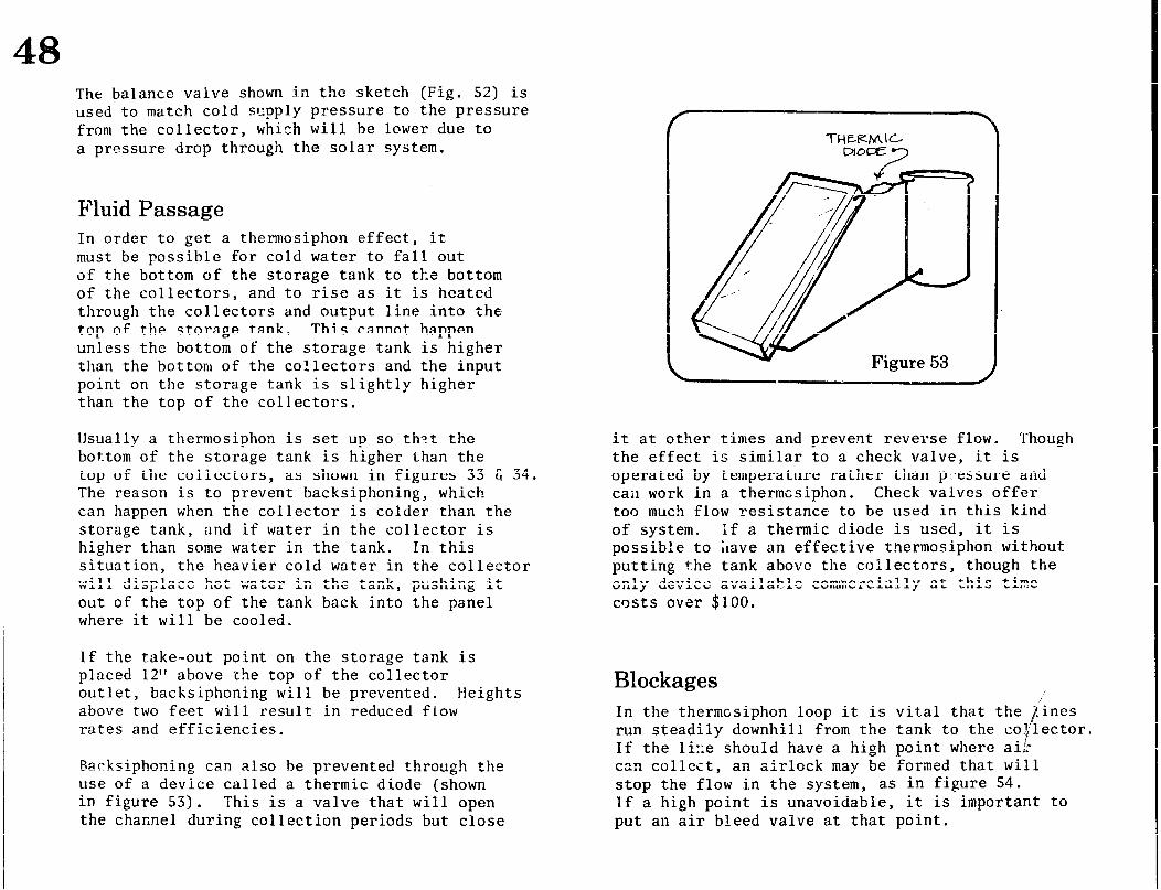
The balance valve shown in the sketch (Fig. 52) is used to match cold sqply pressure to the pressure from the collector, which will be lower due to a pressure drop through the solar system.
Fluid Passage In order to get a thermosiphon effect, it must be possible for cold water to fall out of the bottom of the storage tank to the bottom of the collectors, and to rise as it is heated through the collectors and output line into the top of the storage tank. This cannot happen unless the bottom of the storage tank is higher than the bottom of the collectors and the input point on the storage tank is slightly higher than the top of the collectors.
llsually a thermosiphon is set up so thet the bottom of the storage tank is higher than the top of the collectors, as shown in figures 33 E 34. The reason is to prevent backsiphoning, which can happen when the collector is colder than the storage tank, and if water in the collector is higher than some water in the tank. In this situation, the heavier cold water in the collector will disFlacc hot water in the tank, pushing it out of the top of the tank back into the panel where it will be cooled.
If the take-out point on the storage tank is placed 12” above the top of the collector outlet, backsiphoning will be prevented. Heights above two feet will result in reduced flow rates and efficiencies.
Backsiphoning can also be prevented throtlgh the use of a device called a thermic diode (shown in figure 53) . This is a valve that will open the channel during collection periods but close
it at other times and prevent reverse flow. Though the effect is similar to a check valve, it is operated by temperature rather than p *essure and can work in a thermo siphon. Check valves offer too much flow resistance to be used in this kind of system. If a thermic diode is used, it is possible to Lave an effective thermosiphon without putting the tank above the collectors, though the only device available commercially at this time costs over $100.
Blockages In the thermcsiphon loop it is vital that the lines run steadily downhill from the tank to the co$lector. If the 1i::e should have a high point where ai!: can collect, an airlock may be formed that will stop the flow in the system, as in figure 54. If a high point is unavoidable, it is important to put an air bleed valve at that point.
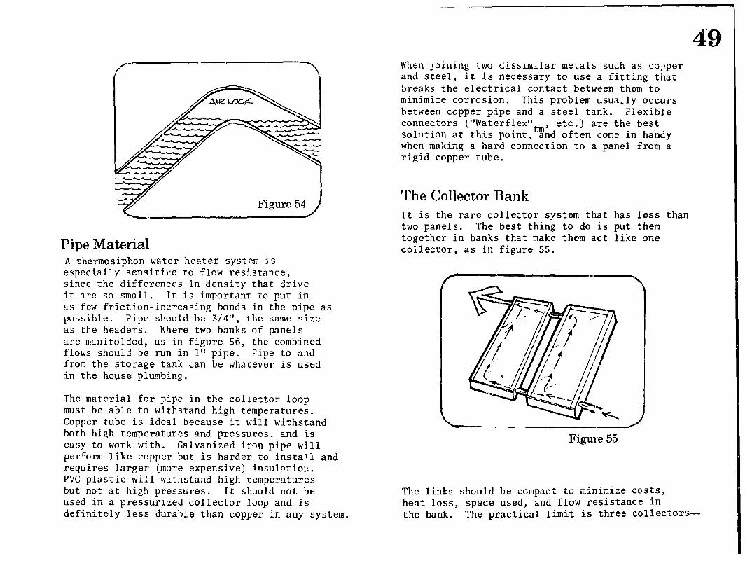
Figure 54
Pipe Material A thermosiphon water heater system is especially sensitive to flow resistance, since the differences in density that drive it are so small. It is important to put in as few friction-increasing bonds in the pipe as possible. Pipe should be 3/d”, the same size as the headers. Where two banks of panels are manifolded, as in figure 56, the combined flows should be run in 1” pipe. Pipe to and from the storage tank can be whatever is used in the house plumbing.
The material for pipe in the collector loop must be able to withstand high temperatures. Copper tube is ideal because it will withstand both high temperatures and pressures, and is easy to work with. Galvanized iron pipe will perform like copper but is harder to install and requires larger (more expensive) inSulatiOi:. PVC plastic will withstand high temperatures but not at high pressures. It should not be used in a pressurized collector loop and is definitely less durable than copper in any system,
When joining two dissimilar metals such as ca:per and steel, it is necessary to use a fitting that breaks the electrical contact between them to minimize corrosion. This problem usually occurs between copper pipe and a steel tank. Flexible connectors (“Waterf lex”
tm’ etc.) are the best
solution at this point, and often come in handy when making a hard connection to a panel from a rigid copper tube.
The Collector Bank It is the rare collector system that has less than two panels. The best thing to do is put them together in banks that make them act like one coilector, as in figure 55.
Figure 55
The links should be compact to minimize costs, heat loss, space used, and flow resistance in the bank. The practical limit is three collectors-
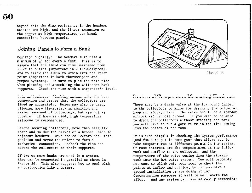
beyond this the flow resistance in the headers becomes too high, and the linear expansion of the copper at high temperatures can break connections between panels.
Joining Panels to Form a Bank
Position properly: The headers must rise a minimum of %” for every 4 feet. This is to assure that the fluid can rise unimpeded from inlet to outlet (important in a thermosiphan), and to al low the fluid to drain from the inlet point (important in both thermosiphon and pumped systems). Be sure to plan for this rise when planning and assembling the collector bank supports . Check the rise with a carpenter’s level
Join collectors: Plumbing unions make the best connection and assure that the collectors are lined up accurately. Hoses may also be used, allowing more flexibility in position and easier movement of collectors, but are not as durable. If hose is used, high temperature silicone is recommended.
Before securing collectors, move them s,lightly apart and solder the halves of a bronze union to adjacent headers, Move the collectors back into position and screw the unions to form a mechanical connection. Recheck the rise and secure the collectors to their supports.
If two or more banks are used in a system, they can be connected in parallel as shown in figure 56. This also suggests how to deal with an obstruction like a dormer.
Figure 56
Drain and Temperature Measuring Hardware
There must be a drain valve at the low point (inlet) to the collectors to allow for draining the collector loop and storage tank. The valve should be a standard silcock with a hose thread. If you wish to be able to drain the collectors without draining the tank you will have to put a gate valve in the line coming from the bottom of the tank.
It is also helpful in checking the system performance (and fun!) to put ir. scme gear that allows j-02 to ,take temperatures at different points in the system. 9f most interest are the temperatures at the inflow tank and outflow to the collector, and the temperature of the water coming from the storage tank into the hot water system. You wi.11 probably not want to climb onto your roof to check the points at inflow and outflow, but if you have a ground installation or are doing it for demonstration purposes it will be well worth the effort. And any system can have an easily accessible
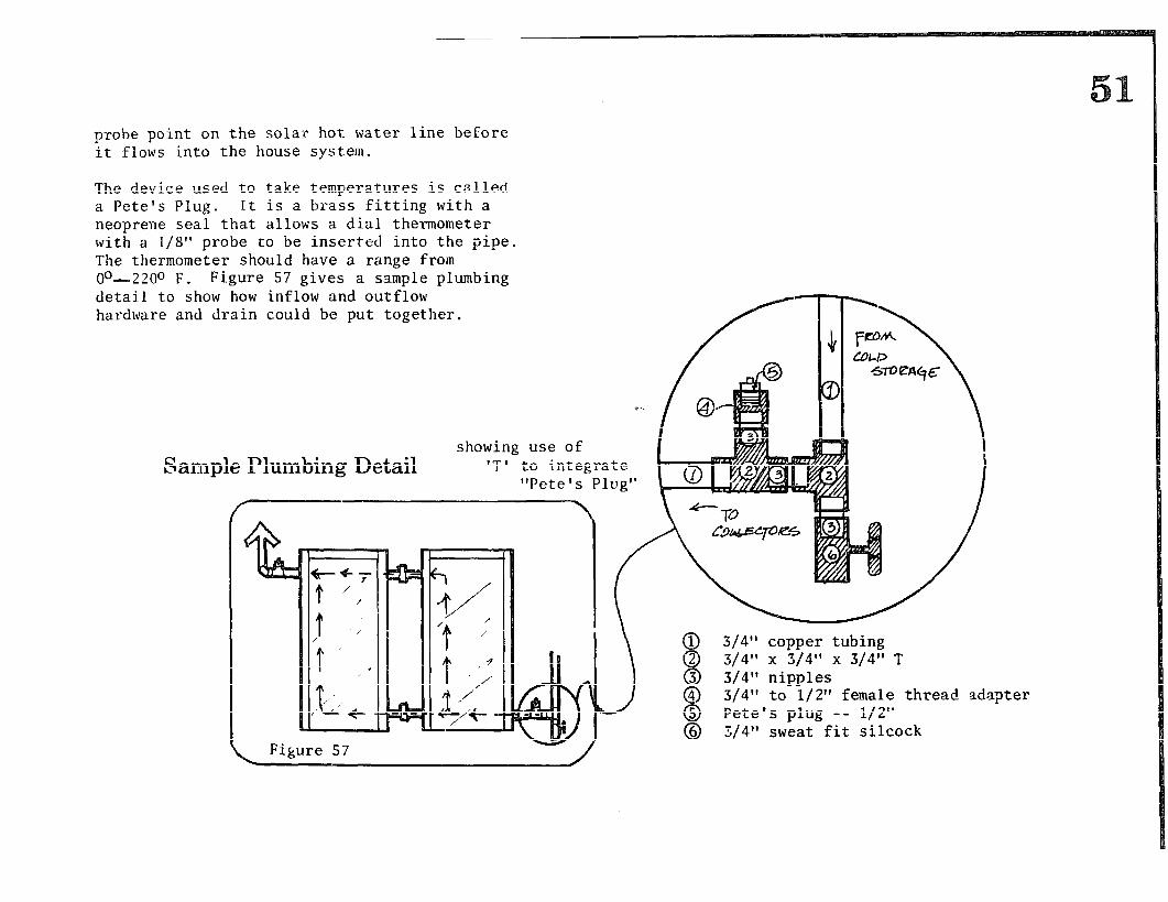
probe po-int on the solar hot water line before it flows into the house system.
The device used to take temperatures is called a Pete’s Plug. It is a brass fitting with a neoprene seal that allows a dial thermometer with a l/S” probe to be inserted into the pipe. The thermometer should have a range from oo--2200 F. Figure 57 gives a sample plumbing detail to show how inflow and outflow hardware and drain could be put together.
Lam c showing use of
.ple Plumbing Detail IT’ to integrate “Pete’s Plug”
L Figure 57
0 3/4” copper tubing @ 3/4” x 3/4” x 3/4” T @ 3/4” nipples 4
8 3/4” to l/2” female thread adapter
& ;/‘;:‘;,f,,;“fr; ;;;;ock
Insulation The lines in the collector loop and the lines connecting storage to the water system must be insulated. Where the lines are outside, the best insulation to use is 1” thick neoprene pipe jacket such as “Armaflex” painted with a coating to prot lim
. It must be ct it from
ultraviolet light and weather; it can be slipped over the pipe during assembly or cut and glued back together with a special contact cement. Cement and protective paint will be available from the insulation dealer. If you cannot find these items locally, order them from the sources in the ‘lAccess’f section.
Where the pipe is well-protected from the elements, it can be insulated with strips cut from standard 3%” fiberglass batts that are stapled around the pipe. This is a bit harder to install than foam jacket, but is much cheaper and gives at least the same insulating value. Fiberglass wrap is not as good.
Storage The storage tank is the digestive tract of your solar system. It is here that the heat from your collectors must move into your drinkable, usable water-- either directly or indirectly. Your system may be set up to let your water flow directly through the collector;, or there may be one or more heat exchangers involved. It all depends on how you choose to deal with freeze protection.
As storage volume decreases from one gallon per
square foot the operating temperature increases and efficiency decreases. If it climbs much above 1.5 gallons the amount of useful grade heat delivered to your hot water system decreases!
The size of the storage tank is determined by the area of your collector. The basic rule of thumb is a gallon to one and a half gallons of storage capacity for every square foot of collector area.
There are some other rules that apply to storage tanks. First, insulate the storage tank and protect it from the weather. The insulating layer should have an R value of at least 20 (7” of fiberglass batt or equivalent). Second, a rule that applies to tanks located inside or above your house, put a drain pan and escape pipe underneath it so that if the tank should leak or overflow, the liquid won’t do a lot of damage before you notice it. The pan can be built out of plywood and lined with a plastic sheet. Make it at least 6” deep. Third, remember to electrically insulate a steel tank from copper pipe. It is also wise to equip the tank with a new cathode (the third plug on top of a water heater tank) to prevent it from corroding out.
Air Venting An enclosed tank will require an air bleed valve at the top to insure that it can fill with air. A float-type air bleed such as an Amtrol #700 works well. This valve should be within the insulating shield of the tank to prevent it from freezing. Certain active systems require different valves to allow an.air supply to enter the system for drainage. Refer to the section on “Active Systems” for information.
Pressure Relief
If the storage tank is sealed, pressures in the system may occur that are dangerous. Protection is provided by a temperature-actuated pressure relief valve on the tank. Get one set for 180° psi with a long probe. It is generally installed on a ‘T’ with the hot water outlet coming out the side. This valve should also be placed within the insulating tank cover for freeze protection-- a line should be run outside of the protective housing or attic to avoid water damage.
s The system that has been described is a thermosiphon system-- that is, one that uses only natural forces to cause the water tc flow through the collector. A thermosiphon system requires that the storage tank be placed above the collectors since the hottest water will be pushed up to the highest point in the loop. What if you can’t possibly mount a storage tank above your collectors? Your roof may not be strong enough, you might not have a place fcr the tank, or the building code might not allow it. In that case, the storage tank will have to be located below the collectors, requiring a pump to circulate water through the system. Such a system is called active, because it requires pumps and controls to move fluids through the system.
Active systems are generally more complex, for they require more maintenance and use an outside energy source to run the pumps. Because they use electronically controlled valves and pumps, they
are more likely to break down. Also, they are more expensive. It is for these reasons that we recommend a thermosiphon design for the do-it- yourselfer. But if you must go to an active system, there are added benefits you should know about beyond the flexibility of storage location.
One immediate benefit is that you may build the workshop collector using smaller diameter risers, manifolds, and supply lines. Whereas $I1 risers and 3/4” manifolds are used in the thermosiphon collector to maximize flow, the increased friction caused by 3/8” risers and $” manifolds (which impede the flow of water) can easily be overcome by the pump. Smaller diameter pipe costs less, so part of the money you put i:?to the pump will be saved in the cost of the absorber panel.
Another advantage of an active system is that higher fluid flow rates can be realized, making the system more efficient. This is because faster moving water can carry more heat away from the collector. It will keep the collector at a cooler temperature so that less heat will be allowed to escape through the glazing. Higher system efficiency means more energy savings.
The Workshop System as Active Solar The least complicated active system that doesn’t require manual control of the pump is shown in figure 58. The only difference between this system and the thermosiphon system described before is that a circulating pump is placed between the storage tank and the collector inlet pipe. A special control autematically turns the pump on and off. The pump circtilates water through the collectors and storage tank at a rate of about two gallons/minute for two
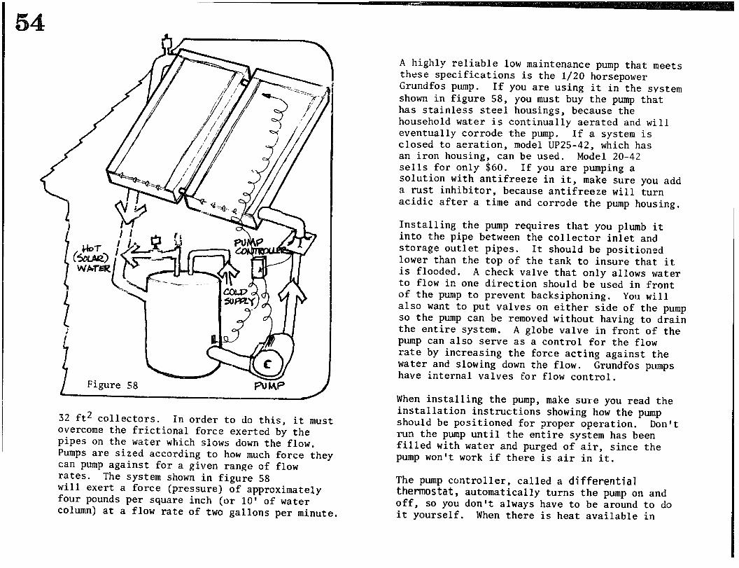
I Figure 58
32 ft2 collectors. In order to do this, it must overcome the frictional force exerted by the pipes in the water which slows down the flow. Pumps are sized according to how much force they can pump against for a given range of flow rates. The system shown in figure 58 will exert a force (pressure) of approximately four pounds per square inch (or 10’ of water column) at a flow rate of two gallons per minute.
A highly reliable low maintenance pump that meets these specifications is the l/20 horsepower Grundfos pump. If you are using it in the system shown in figure 58, you must buy the pump that has stainless steel housings, because the household water is continually aerated and will eventually corrode the pump. If a system is closed to aeration, model UP25-42, which has an iron housing, can be used. Model 20-42 sells for only $60. If you are pumping a solution with antifreeze in it, make sure you add a rust inhibitor, because antifreeze will turn acidic after a time and corrode the pump housing,
Installing the pump requires that you plumb it into the pipe between the collector inlet and storage outlet pipes. It should be positioned lower than the top of the tank to insure that it is flooded. A check valve that only allows water to flow in one direction should be used in front of the pump to prevent backsiphoning. You will also want to put valves on either side of the pump so the pump can be removed without having to drain the entire system. A globe valve in front of the pump can also serve as a control for the flow rate by increasing the force acting against the water and slowing down the flow. Grundfos pumps have internal valves for flow control.
When installing the pump, make sure you read the installation instructions showing how the pump should be positioned for proper operation. Don’t run the pump until the entire system has been filled with water and purged of air, since the pump won’t work if there is air in it.
The pump controller, called a differential thermostat, automatically turns the pump on and off, so you don’t always have to be around to do it yourself. When there is heat available in
the solar collectors that needs to be transferred to storage, the controller senses the temperature difference and turns the pump on. If the collector is hotter by, say, loo F than the water in storage, the pump is turned on. When the temperature of the collector falls to less than 30 F than that of storage, the pump turns off. Controllers can be purchased from Rho Sigma and i-feliotrope at a cost of $55--60.
To install the differential thermostat, bond one of the sensors to the collector outlet pipe and one to the middle of the storage tank with a thermal cement that should be supplied by the manufacturer. Plug the pump into the socket in the thermostat and plug the thermostat into the wall socket, and you’re ready to go. Set the thermostat so the pump goes on at a difference between storage and collectors of 10G F and off at 3’ difference. Consult the instructions. Test out the operation of the pump/thermostat system by measuring the collector outlet temperature and the storage temperature with a thermometer, Make sure the pump turns off when there is less than a 3O F difference between these two points.
Drain Back System If the added cost and complexity of an active system doesn’t prevent problems for you, you may want to consider any one of the many system designs possible in which pumps,automatic controls, solenoid valves and special heat exchangers are used. An exhaustive survey of all those possible designs is far beyond the scope and purpose of this part of the manual. Instead, we will describe one popular design that uses an innovative scheme for freeze protection- the drain back system.
We hope you will have a better idea from this discussion of how a more complex design can overcome engineering problems such as freeze protection.
The drain-back system, shown in figure 59, offers a clever method of draining water out of the co!.lector when the collectors are not absorbing hea. t . It works like this: when heat is being collected by the solar panels, the differential thermostat turns the pump on. Water in the outer
Figure 59
tank is pushed up through the collectors, capturing the heat that is in the absorber plate. The water then flows back to the outer storage tank and gives its heat up to the cooler water in the inner storage tank. The cooled water in the outer tank then falls to the bottom of the outer tank, where it is once again pumped to the collectors.
NGW if the solar panels aren’t collecting heat- if it’s nighttime or a very cloudy day- the differential thermostat turns off the pump, All of the water in the collectors and pipes will then drain back to the outer storage tank, leaving the collector pipes emptied of water and protected from freezing. In order for draining to occdr, outside air must be allowed to enter the collectors and replace the drained water. Air enters the collectors through an automatic air valve mounted at the high point in the system.
The air valve is necessary in much the same way that a tomato juice can needs a second hole to pour properly. (This valve should be wrapped with a small heat tape and insulated to make sure that it doesn’t freeze.) When the pump turns on again, air is purged from the system through the same air valve, which is set to open when the pump turns off.
The special parts for the drain back system are: an automatic bleed valve, a temperature controller with a pre-set off point, the tank-in-tank heat exchanger, and a larger horsepower- pump.
A few words about the pump for a Grain back system: in the example we showed before, the only forces acting,against the pump were the frictional forces of water moving against pipe
walls. The water circulated in a closed loop; for every portion of water being pushed up to the collector, there was another portion going down by gravity and eventually going back through the pump. When we start up the drain back system, however Z the situation is different. The pump must push the water up to the collectors without the aid of downflowing water giving its energy back to the loop. The additional force that the pump must push against is determined exactly by knowing how many feet the highest point is above the pur~p. The force is then equal to the weight of a column of water that high.
If the height is 20 feet, then the pressure (force per unit area) will be nine pounds per square inch. The pump must overcome 9 psi in addition to the frictional forces explained before. A pump of about l/12 hp will provide the extra power needed to pump against the weight of the water. A size reducer on the end of the return pipe at the point just above the fluid level in the outer tank seems to reduce the start-up effort required by the pump.
A basic rule to follow when choosing your own design is to first decide exactly what you need to have accomplished and then to do it within the constraints of your house, climate, and lifestyle and budget in the simplest way possible. It’s easy to over-design once you get a few fancy electric toys. Even though we’ve seen it done, you don’t have to use a computer to get hot water from the sun.
57 whenever the temperature inside the pipe’s insulating jacket drops to 32O F. This usually means that the fresh water supply line and solar hot return line should have electrical heat tape placed under the insulation. If a good layer of insulation is used and the contact is snug, the tape can be run along the pipe rather than wrapped around it. If there is a cold spell combined with a power failure, drain the lines.
Protecting the collectors by heating them is a higher risk proposition. There are two basic approaches: electrical heat tape and hot water recirculation with a small p-ump. These will be effective only in regions with mild climates because otherwise the heat value spent in protecting the system minimizes the total savings produced by it.
However the real problem in any freezing climate is reliability. Because both systems run on electricity and because it is only feasible to design them to protect to an average low temperature, sooner or later they will fail. Either the power will go off during a cold spell or a below average freeze will arrive.
Heat tape has advantages in a mild climate that may make the risk seem worth it to you. It allows use of a direct heat system with the cold water supply cooling the collector. It is easy and cheap to install and fully automatic in operation. We have experienced minimal success and hard failure with it. The problems in our installations have been : 1) thermostat failure; 2) failure to plug it in or keep it connected; 3) temperature below the design temperature (lo-
year low). If you live in a mild climate with a reliable
reeze rotectisn The availability and unique physical properties of ,;ater make it an excellent liquid for collecting and storing solar heat. Since potable (drinkable) domestic water is probably what you are trying to heat, the most direct way of heating is to circulate your potable water through the collectnrs D If the cold water supply enters the storage tank at a T on the thermosiphon line that goes to the collectors, the cold water will be drawn through them whenever hot water is used. This will cool the collectors and increase their efficiency.
One drawback is that water freezes at 32O F (00 C). In climates where there is any possibility of freezing temperatures, some safeguards against freezing must be designed into the solar water heating system.
There are five methods that can be used to prevent freezing: 1) Heat the collectors and exposed pipes; 2) Use a non-freezing fluid to circulate in a
closed loop through the collectors; 3) Drain water from the collectors; 4) Co?ler the collectors with movable insulation; 5) Design a system that is not hurt by freezing.
Heating the Collectors and Exposed Pipes If pipes containing fresh water must be located outside or in unheated attic spaces where severe cold temperatures occur, they should be heated
power supply and decide to use heat tape, get one tape for each collector and test it before instalRing. The best common brand we have seen in Smith-Gate B which comes with a detachable replaceable thermostit. The tape should have six watts for every square foot of collector. For example, for a 30 ft* collector, put in a heat tape with a total wattage of 180. This will give protection to about 12’ F. The cost varies with your climate and electricity rates.
The heat tape is taped to the back of the absorber plate. It should be laid flat in a serpentine pattern and not twisted or crossed, or put in contact with sharp tie wire ends. The fiberglass will push it snugly against the absorber plate once in the box. The thermostat is mounted outside the box in its own weatherproof container (which should be painted black). Power should be delivered to the tape at a good exterior box; the connection must be out of the weather.
The tape will take heat up to 200’ F. If the collector is drained or stagnated, it is necessary to cover the collector to prevent overheating. If cold temperatures below 12O F are expected or if the power goes out when temperatures are 35” F or lower, drain the collectors.
Recirculation Water recirculation is something we don’t have any experience with. It appears that it would radiate large amounts of storage heat to the sky. To do it requires a small pump with a controller (see “Active Systems” section). To incorporate recirculation into a thermosiphon and still have unimpeded flow would require an
elaborate bypass or an interesting pump.
Non-Freezing Collector Fluid
When freezing temperatures are common, another solution is to circulate a non-freezing fluid in a closed loop through the collectors. This method involves construction or purchase of’ a ‘heat exchanger’ that allows transfer of heat from the collector fluid to domestic potable water without allowing the two liquids to mix.
An antifreeze system is reliable if maintained properly. Its major disadvantage is that it is less efficient than a direct heating system because of the heat exchanger losses and its inability to cool the collector with the cold water supply. The initial cost is higher and precautions must be taken to prevent anti-freeze solution from mixing with the domestic water if a leak should occur. Finally, fluids can become corrosive and therefore must be checked once a :zrear.
The major design factors are the anti-freeze fluid used and the type of heat exchanger chosen. (See the “Heat Exchangers” section for further discussion.) Because anti-freeze is expensive and has to be replaced every three years or so the system is usually designed to use as little as possible.
Several kinds of anti-freeze are available, and the kind chosen will have effects on the rest of the system. If you use a toxic anti-freeze such as ethylene glycol (car anti-freeze), plumbing codes require that there be two metal surfaces between the anti-freeze and domestic water. This is hard to do on a do-it-yourself basis and the commercial heat exchangers that meet the requirements
59 are expensive and usually designed for pumped systems.
Unless it’s within your means or capabilities to buy or build a double-wall metal heat exchanger, we recommend you use a non-toxic anti-freeze with non-toxic corrosion inhibitors. Propylene glycol with dipotassium phosphate will work, as will various commercial collector fluids. Be careful not to use silicone oils in a homemade system, however. Though they are not toxic, they are also expensive and much lower in heat capacity than water-base solutions. They are so viscous (thick) that they will not thermosiphon readily and the surface tension is so low that they may go through soldered connections that will contain pressurized water. Present silicone fluids are best left to pumped systems with high flow rates using commercial collectors installed and guaranteed by professionals.
Draining Water from Collectors This method involves the appropriate placement of valves in the system to completely drain the water from collectors and exposed pipes whenever freezing temperatures are a threat. This can be done in a variety of ways, either automatically or manually. Or you may prefer to drain the system for the entire winter and use an alternate method to heat water during the coldest months.
One advantage in a drainable system is that it can be designed to allow for direct heating of domestic water. The simplest type is one that is drained, tank and all, and covered when freezing can be expected, then filled up again when spring comes. This is a very reasonable choice in a region where the sun disappears
behind clouds for most of the winter. (Heat tape might be a reasonable emergency back-up in such a system; be sure to disconnect it when the collectors are drained.)
Most drainable systems are designed to catch the sun during the day, pack it into the storage tank, and only drain the collectors during the night and other intolerably cold sunless times.
In a pumped system this is easily done in many different ways. (See the section on “Active Systems .I’) But in a thermosiphon it is hard to do because the tank must be closed off from the collectors to prevent it from draining. To manually operate three valves twice a day during cold weather is a lot to expect most people to do. An automatic system would require a controller with an automatic air vent, and three solenoid- operated valves, which becomes complicated and expensive. (For a schematic on a workable set-up, see the materials available from the Domestic Technology Institute i-n the l’Access” section.)
When automatically operated controls and valves are used, their correct placement is essential. Timing and operation must be checked regularly. Automatic draining and refilling procedures are only as reliable as the system design and components make them. In any automatic drainable system, pumped or thermosiphon, the controls should be set for automatic drainage if there is a power failure.
Movable Insulation Use of movable insulation may be cheap and adequate in the warmest of climates, but it is not convenient or practical in most cases,, and is not easily automated. It may be used as a back-up in conjunction with heating the collectors to give
extra protecticn during cold spells.
Another freeze protection that allows use of a direct heating thermosiphon is to put movable insulation over the absorber plate or collector when freezing conditions exist. The insulation must be weatherproof and cover all exposed equipment. In very cold weather, collectors protected only with insulation will probably freeze anyway. It works best on collectors that have a lot of stored heat in them, such as bread box collectors.
It is possible to design systems that can absorb the expansion of ice without exploding. For example, if a flexible tube is inserted in a pipe, the expansion will crush it before it bursts the pipe wall. Putting a working system together is a hard problem, and it may be beyond the scope of do-it-yourself technology.
eat Exchangers A heat exchanger allows transfer of heat from one fluid to another without allowing the two fluids to ‘nix. (The term ‘fluid’ here is used to include gases, such as air.) A common type of heat exchanger you have probably used is a radiator; heat is transferred from the moving water through the metal to the air, which carries it away by convect ion.
There are two important points here that are common to all types of heat exchangers. First, there must be a difference in temperature between the two fluids, for heat always travels from a warmer area to a colder one. The greater the difference to begin with, the more efficient the transfer of heat will be.
The secol,d point is that the transfer is aided by the motion of the two fluids. As the warmer fluid gives off its heat, it is replaced by more warm fluid that rises to the point of exchange. The exchange will be efficient if the cooler fluid can carry the heat away as it warms up, and be replaced by more cool fluid. If the cooler fluid cannot circulate, it will gradually approach the temperature of the warmer fluid and wil; not be able to absorb any more heat. But no matter how efficient the exchange, no heat exchanger is 100% efficient; some heat will always be lost to the environment.
The first heat exchanger used in a solar water heating system has already been discussed: the absorber plate. As we have seen, the heat that enters the collector passes through the metal pipes
and heats the collector fluid, This fluid then flows into the storage tank carrying the heat with it, and is replaced by colder fluid.
Tank-In-Tank There is a second type of heat exchanger with which ;‘OLJ must also be concerned if you decide to use an anti-freeze fluid for freeze protection: the one that transfers the heat from the collector fluid tc the domestic potable water. There are several things to consider here besides the heat exchange efficiency: compatibility wi,th a thermosiphon system; cost; availability of parts and ease of building it yourself; assurance that there can be no mixing of the two fluids; and minimal maintenance.
The heat exchanger pictured in figure 60 is the tank-in-tank type. The domestic potable water is held in a pressurized tank that sits in another tank, while the heated collector fluid circulates in the space between. Since there i a large mass of water to be heated relative to the collector fluid, heat exchange can be quite efficient, Also, since the potable water stays in contact with the hot collector fluid over a period of time, it has a chance to get hot enough for use without a back-up system (at least during most of the year). This is a good design to use in a thermosiphon system like ours since there is relatively little flow resistance. And it is relatively easy to build yourself.
There are some disadvantages, however. If a steel inner tank is used the collector fluid can corrode it and cause a leak. This can be prevented by adding an anti-corrosive to the collector fluid. If a glass-lined steel or double-walled tank is used, heat conduction will
be reduced I A more efficient tank, tholigh far more expensive, is a single-walled copper tank.
Figure 60
Finally, although the water in this system will be hotter, there will be less of it. Once the hot water in the inner tank is gone, you must wait fcr another batch of water to be heated or use a back-up system.
To build this type of heat exchanger you can use a steel pressure tank placed inside another tank. If possible, use a new pressure tank; the average life of a tank is six years. If you use a recycled hot water tank, chances are it may be ready to go- at the very least, make sure the tank is equipped with a new anode. Because the center tank is not under pressure it can be made from non-corrosive plastic. A high density polyethylene or polypropylene tank is best, but fiberglass tubes can also be used. A 55-gallon drum will probably rust out at the bottom within a short time; if you must use one seal the inside of that seam with silicone caulk. The outer tank should be sized large enough to allow the inner tank to slip in with a 1” space all around it.
Make two holes in the outer tank for the pipes carrying hot collector fluid in and cold out, and install CPVC tank adapters t.o 3/4” male pipe thread. It is also wise to put in an overflow line leaving the outer tank at a point above the maximum normal collector fluid level. If the inner tank should leak this will prevent damage to the insulation and house. The pressure tank should be set on a support that holds it slightly off the bottom of the outer tank.
The tanks are now ready to be hooked up to the system. When the outer tanK is filled, float 2’ of oil on top of the fluid to prevent evaporation, then cover to keep the insulation out.
Coil In Tank In contrast to the tank-in-tank heat exchanger, the coil-in-tank design (figure 61) will not heat the water as hot, but will provide more of it.
F -7 ANT/- CI~HOPJ
/- VACUUM 6tz~mR
\ Figure 61
63 The domestic water passes through a coil, where it picks up heat from the surrounding collector fluid . Since most of the heat exchange occurs only when water is being drawn from the tap, and the domestic water is flowing relatively quickly, the water will not be heated much over 80° F. This means you must always have a back-up system to heat the water up to the desired 120° F. However, this system can provide up to 140 gallons of 80° water before the stored heat is used up. The copper tubing is an excellent heat conductor, and the continuous flow of cold water has a very large heat sink capacity, insuri-ng heat exchange.
You can also make a coil-i::-tank heat exchanger yourself, although it will probably be more expensive due to the large amLunt of copper coil. Another additional expense will be the large quantity of anti-freeze solution that will be needed to protect the storage tank. To provide adequate heat exchange, you’ll need at least 60 feet of copper coil for a 55-gallon tank. Although there should be no corrosion problem associated with copper, if you are required to have a double-walled heat exchanger, this won’t meet code. Some progressive codes will accept the anti-siphon vacuum breaker as adequate poison protection, however, Plumb as shown in the illustration, using the kind of water level make-up valve commonly found in toilets.
Another option you may want to consider is a purchased heat exchanger. These can be much more efficient than the ones you build yourself, will almost certainly meet code, and can save you a lot of trouble if you are unccitain about design or in a hurry. These are usually the inverse of the coil-in-tank already shown: heated collector fluid flows through the copper coil, which passes through a tank of domestic
water. This design requires a pressurized water storage tank, making it nearly impossible to build yourself. The copper coil may also thwart the thermosiphon by putting up too much flow resistance. However, if you’re using an active system it may be worth it to buy a ready-made heat exchanger.
Anti-Freeze If you use either of our home-built heat exchangers you cannot use a toxic anti-freeze. The cheapest option is to buy propylene glycol and use it in a 20% to 50% solution, depending on how cold it gets at your site. A 50% solution offers protection to well below zero degrees. The anti-freeze should have dipotassium phosphate (K2HPO4) added to it to prevent corrosion. The ratio is one pound of dipotassium phosphate to every five gallons of propylene glycol solution used. Mix it with hot water to dissolve it before adding it to the anti-freeze solution. A non-toxic commercial fluid that contains anti-freeze and corrosion inhibitors, such as “Sun Temp,” can also be used.
Every year the collector fluid will have to be tested for acidity and corrosion inhibitor must be added to ir. To test the fluid, use pH paper or blue litmus paper. The litmus paper will turn red if the solution is acidic, and the pH paper will indicate the amount of acidity. The fluid should not be acid. Every five years the solution should be rep1 aced. Every year the solution’s specific gravity must be tested to indicate the level of anti-freeze protection available. Test first at tJle time of installation of establish a base line \/a luc? : The test should be done at the same temperature each time.
If you plan to purchase a commercia'l solar hot water heater, we hope you now have a good understanding of how your investment is constructed, and ho*ti it *tiorks. There are a few more things you should know to help you make a sound decision.
The solar collector industry is young and growing rapidly, so right now there is a flood of unproven systems on the market. Most people buying collectors today are “field testing” some collector company’s product- but this is to be expected when a new technology is introduced into the market. There are a variety of designs among the many collectors available, representing prices ranging from $20 to $40 for 1 ft2 of collector surface. How do you decide what is the right collector for you? That is a hard qllestion to answer, and we offer only a general approach that you may take.
In general, the most important things to look for in a solar hot water heater are: 1) system design and its compatibility with
your climate, lifestyle, and budget; 2) durability and craftwork; 3) manufacturer guarantees, service contracts,
and insurance.
System Design There are so many collector designs around that - -7 ---..2L.l.. -^^^,..,.. -..,.I wt Cail!t yuaa.~u~y I GLUIIULL~;ILU aiiy Oiie tjp. l-l.. IILC designs offer various levels of convenience and different solutions to problems of heat transfer
and freeze protection. Already you know a lot about solar hot water heaters from reading this manual, but you will need to read more about specific systems to be able to make an informed choice.
Efficiency If you compare the efficiencies of different systems, be sure to find out the total system efficiency, including heat exchanger. Ask the manufacturer questions like: On a day that is partly cloudy in October and the average temperature is 50°, how much heat will the collector system add to my domestic hot water heater? Compare a few to each other for different times of the year and outside temperature. Be wary, however, of collector efficiency curves because they only measure the collector performance, not the total system, and it is the entire set-up that gives you hot water.
Durability As you shop around, chances are that you ‘11 find most hot water heaters offer comparable energy savings for a given price range. The big difference will be how well they are made. Craftwork is extremely important because collectors really take a beating from the weather, going through very large extremes in temperature.
The best way to find out about a given hot water heater is to find people who have the system, and ask them about it. If you can’t do that, then you’ll have to estimate the quality of construction yourself. Most people know shoddy work when they SC3 it. I r.nG “““I\ at tbae hnllcinn * .‘Y..U”‘b. is it sealed wnl 1 nr*r,
sturdy and protected against moisture? Is the glazing high-quality, tempered glass or a plastic
65 film? (See the glazing chart on page 9.) Is the glazing sealed well? Does the collector look like it will last 20 years?
Guarantee The solar industry is still young, so lifetime unconditional guarantees are unheard of. However, most manufacturers offer limi.ted guarantees of craftwork that you should consider when making a choice. If you have someone install the collector system, warranties should be expected and a service contract may be available.
Also, be sure to find out if your manufacturer’s system will allow you to be eligible for tax credits and loans. Your insurance company will also want you to buy a reputable system.
(Phew. At this point, you may want to go back to the beginning and build it yourself.)
Components The collector system described in this manual is constructed of materials easily available at most hardware stores. If you have access to any one of the increasing number of solar parts distributors or manufacturers, you may consider purchasing a prefabricated component of the system, such as an absorber panel, glazing housing, a collector box, or heat exchanger. If you are short on time, it may be worth it for you to purchase one or more parts of the system already made, in spite of the added initial cost,
manufacturers advertise high efficiency plates for about $40 more than the cost of the materials needed to make the one described in this manual. The problem with them is that they are hard to get if you only plan to buy one or two. Check around your area, however, to see if they are available and at what cost. The Solar Age Catalogue has an excellent list of manufacturers of solar-components and also contains a comparative list of absorber plates. Be sure you are buying a panel that can be used for a thermosiphon system at high pressures if you are going to use our recommended design. The manufacturer can answer this quest ion.
Another option that you may consider is to purchase a solar water heater kit. A number of excellent kits are available that offer substantial price reductions over regular commercial systems. (See the “Access” section.)
Probably the most cost-effective component to purchase is the absorber panel. Absorber plate
Check the entire system every fall after most of the nearby leaves have fallen, but before really bad weather. Do this on a sunny day when collection should be occurring.
Glazing: Clean with soap and water. Some plastics may require special techniques; check with the manufacturer. If you live in a particularly dirty atmosphere, you may want to clean the glazing more than once a year. Check for cracks. If the gap i.s not too large, it can be mended with silicone caulking, Otherwise, you will have to replace the glazing.
Supporting Structure: Check wood for moisture penetration or peeling paint. Sand down the problem areas, dry thoroughly, prime, and re-paint.
Roof Penetration: Leaks here can cause big problems. Check flashing and roof sealant and repair if necessary. Be sure the flow of rain water around the installation isn’t blocked.
Fluid Passage: Problems here can be freezing temperatures, blockage, or corrosion. Check all the pipe fixtures you can get to for possible leaks.
Blockages: These are usually due to air locks, places where air forms a pocket in a high portion of the pipe and prevents the fluid from flowing. The flow should be guing into the bottom of the collectors and out the top. If the temperature of the outgoing fluid is very high relative to the incoming fluid (800 F or more), this indicates a blockage.
Anti-Freeze (if used): Take out a sample of anti-freeze solution and take it to a gas station. Ask them to check its specific gravity; this tells you indirectly how cold it can get before the collector contents will freeze. Use litmus paper to check the acidity of the anti-freeze. (Follow the instructions that come with the litmus paper.) If acidity has occurred, or at least every five years, the anti-freeze solution should be replaced and the new solution tested.
Corrosion: If your system uses anti-freeze, an inhibitor should be added every year to prevent corrosion. Dipotassium phosphate is added at a ratio of one pound to every five gallons of propylene glycol solution. (See page 63 for more specific details.)
Drain Back System (if used): Check the controls for the air bleed and check the valves, especially the pressure relief valves, to make sure they don’t stick, If they’re stuck, refer to the product information or a plumber.
Recent experience with solar hot water systems shows that proper installation is most essential to proper functioning. For more information on the types of things to watch out for, read “New England Electric’s Solar Project,” Solar Age, March 1978. P. 16+
I Caution: When the absorber plate is empty of fluid, it is possible for the collector temperature to reach nearly 3000 F. Since this is hard on the collector, we recommend covering the collectors w-ith a sheet of plywood or the equivalent when they are drained.
67
Hot Water Conservation Solar energy is a low-intensity energy source that can only make a significant impact if used efficiently. For that reason, conservation is the first step for the effective use of solar energy, and solar hot water is no exception. Even if you are not using solar energy to heat your water, conservation is important and can save you quite a bit of money. If you have gone to the effort and expense of building a solar water heater, of course you’ll want to maximize the return on your investment.
Tank Insulation: The first step is to keep in al 1 of the heat you can. You’ll want to insulate your storage tank as well as possible, to R-18 or hetter. Even inside an unheated attic, this amount of insulation is necessary. If the tank is on your roof, be sure the insulation is protected by a weathertight cover, or the rain will soon make it useless. If the solar system feeds into a convent ional water heater tank, be sure that tank is also very well insulated.
You can buy ii commercial water heater jacket from your utility for $I?-- 30, or you can use fiberglass batting to wrap the tank, fastening it with staples or duct tape. It’s equally important to insulate all hot water pipes, both inside and outside the !louse. It can even help to insulate the first few feet of cold water pipe going into the storage tank. Another good idea is 3 heat trap-- ;I kink in the intake and outflow pi pcs that prevents a convect ion current from carrying away heat from the tank. Utilities often use them when installing a new tank. They are also available from many hardware stores,
See “The System’s Piping” section for specifics on pipe insulation materials and techniques.
Stopping Drips: Two other quick ‘fix-its’ can also save you a lot of hot water. The first is fixing all your leaky faucets, an obvious thing to do but one that many people neglect all too often. Dripping faucets can waste up to 300 gallons a month.
Flow Restrictors: The other trick is to install flow restrictors in your faucets and shower head. These can range from an inexpensive plastic ring that is inserted into the fixture, to a sink aerator or shower head that can be pre-set to the desired rate of witter flow. Many utilities either give away plastic flow rcstrictors or have bargain rates on restricting shower heads. Most hardware stores sell shower heads and aerators; prices vary by as much as $10, as do quality and flow rates, so shop around.
The r‘low restrictor compresses the water as it passes through the tap, so that even though less water comes through, it comes out harder. Most people don’t notice a difference in the way the shower feels, but their water use is cut in half.
Efficient Use: It is also important to use appliances efficiently. Your automatic dishwasher uses eight to 10 gallons of hot water per load, so you’ll want to load it as full as possible for each use. You can also use cold water to rinse the dishes beforehand. If you are buying a new dishwasher, invest’gate those that use less water and have cycles you can control. The same is true when buying a washing machine. It’s even possible to buy machines that recirculate some of the hot water. Most of the time, though, your clothes
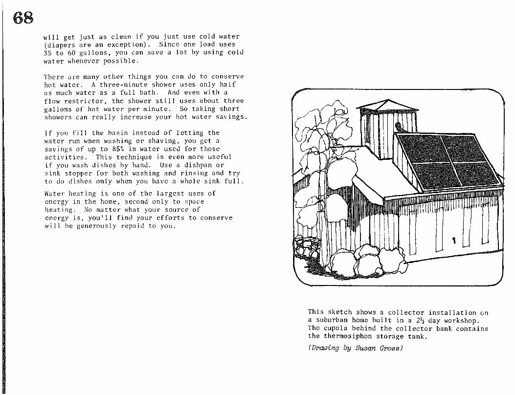
will get just as clean if you just use cold water (diapers are an exception). Since one load uses 35 to SO gallons, you can save a lot by using cold water whenever possible.
There are many other things you can do to conserve hot water. A three-minute shower uses only half as much water as a full bath. And even with a flow restrictor, the shower still uses about three gallons of hot water per minute. So t.aking short showers can really increase your hot water savings.
If you fill the basin instead of letting the water run when washing or shaving, you get a savings of up to 855 in water used for those activities. This technique is even more useful if you wash dishes by hand. Use a dishpan or sink stopper for both washing and rinsing and try to do dishes only when you have a whole sink full.
Water heating is one of the largest uses of energy in the home, second only to space heating. No matter what your source of energy is, you’ll find your efforts to conserve will be generously repaid to you.
This sketch shows a collector instaliation on a suburban home built in a 2$ day workshop. The cupola behind the collector bank contains the thermosiphon storage tank.
(Drawing by Susan Gross)
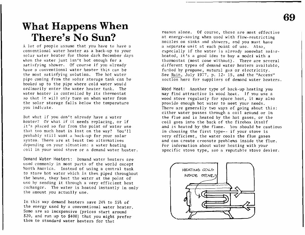
69
A lot of people assume that you have to have a conventional water heater as a back-up to your solar water heater for those dark December days when the water just isn’t hot enough for a satisfying shower. Of course if you already have a conventional water heater this can be the most satisfying solution. The hot water pipe coming from the solar storage tank can be hooked up to the pipe where cold water would ordinarily enter the water heater tank. The water heater is controlled by its thermostat so that it will only turn on when water from the solar storage falls below the temperature you indicate.
Rut what if you don ’ t already have a water heater? Or what if it needs replacing, or if it’s placed so far from the point of water use that too much heat is lost on the way? You’ll probably still want a back-up for your solar system. There are at least two alternatives dcpcnding on your situation: a water heating coil in your wood st,ove or n demand water heater.
Demand Water Heaters: Demand water heaters are used commonly in most parts of the world except North America. Instead of using a central tank to store hot water which is then piped throughout the house, they heat the water at the point of use by sending it through a very efficient heat exchanger. The water is heated instantly in only the amount you actually use.
In this way demand heaters save 24% to 55% of the energy used by a conventional water heater. Some are so inexpensive (prices start around $20, and run up to $400) that you might prefer them to standard water heaters for that
reason alone. Of course, these are most effective at energy-saving when used with flow-restricting nozzles on sinks and showers, and you must have a separate unit at each point of use. Also, especially if the water is already somewhat solar- heated, it’s a good idea to buy a model with a thermostat (most come without). There are several different types of demand water heaters available, fu.?led by propane, natural gas or electricity. See Rain, July 1977, p. 12- 15, and the “Access” section here for suppliers of demand water heaters.
Wood Heat: Another type of back-up heating you may find attractive is wood heat. If you use a wood stove regularly for space heat, it may also provide enough hot tiater to meet your needs. There are generally two ways of going about this either water passes through a coil around or in the flue and is heated by the hot gases, or the coil goes into the back of the firebox itself and is heated by the flame. You should be cauti’ in choosing the first type-- if your stove is very efficient, the water cools the flue gases
ous
and can create creosote problems inside the flue. For information about water heating with your specific stove type, see a reputable stove dealer.
anizing a Workshop Hands-on workshops are a truly fine way to share skills and information if properly done. The participants learn from each other, and the teachers learn more with each workshop. An additional advantage of workshops over classroom instruction is that working systems actually get built while all this learning is taking place.
Scope of Workshop
The first step when preparing for a workshop is to decide what the scope of work will be. Several options are available. The simplest is to build a collector panel and set it up in a demonstration thermosiphon loop with hoses. This can be done in a single day with experienced teachers, skilled participants and a well- equipped shop. Allow l$ to 2 days for less optimal situations.
The most demanding workshop is to build two collectors and move as far toward permanent installation as possible. This option is the most popular, and the one presented here. A variation of this is to separate the collector building from the installation, and nave two workshops of two days each. Another type of workshop we have conducted is a maintenance workshop for collectors damaged by exposure to sun while empty.
Contractual Arrangements
Workshops can be set up by the teachers or by a
sponsoring organization or individual. If a permanant installation is being attempted, then a site owner is involved in some capacity-- in many cases the owner is the sponsor. The most complex situation has a separate sponsor, teacher, site-owner and tenant.
Whenever more than one party is involved. the question of allocating responsibilities and outlining the scope of the work becomes very important. Without both clear understandings and plenty of goodwill, the workshop may end up with cold water and bad feelings. The major points that have to be made clear are:
I) Workshop Limits: Everyone must understand that the primary function of a workshop is to teach and learn-- not to build. This fact, coupled with other factors such as participant skills, site, weather, materials availability and tool dependability mean that the actual output of the workshop is unpredictable. Therefore, we never guarantee complete installation of a system built in a workshop. We do guarantee to leave the owner-tenant. in a position to complete the installation, providing advisory support as necessary.
2) Authorization to Build: You must be sure that there is clear written permission to proceed, -.- from the property owner or from the tenant if s/he has legal authority to make improvements. (The basis of this authority should be stated in the written agreement.)
3) Legal Responsibility for Accidents: Teachers should be responsible only for injuries resulting directly from the actions of themselves or their staff. This should be stated in the written memo of agreement. This means the balance of the responsibility falls on the sponsor and site owner or tenant. Disclaimers of responsibility by these parties, even if signed by the participants,
71 will probably not legally prevent successful suit by participants injured because of negligence. Teachers should be covered by their employer with liability insurance.
4) Payment: The amount the teachers are to be paid, time of payment, and who is to pay should be clearly specified.
5) Travel, Food and Lodging: If you as a teacher have to travel and pay for meals and lodging, it should be agreed upon that your expenses will be covered, Of course, one reason we are writing this is to spread the expertise to other teachers and minimize our travel.
6) Scope of Work: It, should be clearly stated in the memo of agreement that the teachers will do certain tasks within certain time frames for an educational purpose. For instance: give a slide show on solar water heating and workshop construction on Friday night, 7:30--9:30; conduct hands-on workshops on collector building from 9:00 a.m. to 5:30 p.m. on Saturday and Sunday. An overtime charge provision should be included if circumstances force work into evening hours. Although we have always been flexible about this, it is very useful to have this understanding before the workshop.
7) Pub1 icity Work: Responsibility for doing PR should clearly be agreed upon to ensure that it is done and to avoid confusion. Content should also be agreed upon-- teachers should be given credit in the publicity.
8) Enrolling Participants and Taking Fees: There must be clear agreement on who registers participants, takes fees, and answers questions. Registration materials and PR should direct potential participants to the proper person. This is an important job and involves a lot of
work. It is necessary to have registration in only one place and that registration people are kept well-informed of the planned program and other details. Inconsistency creates confusion.
9) Materials Purchase: It must be clear who orders and picks up materials and who pays for them. In most cases, the owner or tenant pays for materials, but the sponsor acts as purchasing agent, with the teachers (if separate from the sponsor) giving advice about fair prices, substitutions, and sources of supply.
10) Code and Permits: In ali cases there is the possibility that a building or plumbing inspector will become involved in the process-- the likelihood depends on your location. It is wise to agree in advance about who is responsible for dealing with this. In many areas, that party will automatically be applying for permits. In most areas, the owner or tenant should be responsible because technically s/he is doing the building-- and the Codes generally allow an owner to do the work rather than forcing use of a licensed carpenter and plumber. The owner- tenant will need support from the teachers in applying for a permit. The extent of this aid will vary with each workshop, from advice to complete plans.
11) Plans and Drawing: There should be a complete understanding about the types of planning and the technical level of drawings the teachers will supply. These plans can range from sketches and ideas to complete materials lists, working drawings and plumbing schematics needed to get building and plumbing permits. The amount of fee charged by the teachers can be greatly affected by the plan requirements.
12) Workshop Management: There should be a cordial but clear understanding about who is
72 running the workshop as far as the participants are concerned. Because it is primarily an educational experience, it should be agreed that the teachers manage the workshop. The tenant- owner has important interests and should approach the teachers to make sure they are considered. The sponsor should not be an overt presence, but should be free to advise the teaching staff discreetly, if necessary.
Without goodwill, a written document containing all of the above will not work. But a comprehensive, clear agreement on all of these points will help maintain goodwill. Writing is not necessary but it sometimes helps people remember what they agreed to. Apply these considerations to your own situation and the form, written or oral, will be obvious.
13) Maintenance and Repair of the Collectors after the Workshop: The system described in this manual is a good quality solar system, but no system runs forever without requiring maintenance or repair. Information should be provided to the system’s owner about regular maintenance and professional rcso~lrccs for rcp;lir. The writ ten agrcemc‘nt sho~~lcl clearly dclincatc the teacher’s and the sponsor’s responsibilities if the owner has problems with the system.
14) Lunch and Childcare: Will refreshments and lunch be supplied or will participants be asked to bring their own? It is important that these points be made in the registration materials. The same is true for childcare-- if it is to be provided, arrangements must be made and a notice given far in advance.
Workshop Preparation Finding a Site: The first task is to find a site and reach the necessary agreements with the owner- tenant. Remember this is a do-it-yourself technology. The owner should be enthusiastic and willing to try. Never do a workshop where the owner-tenant can’t or won’t be a participant. The site must be surveyed for solar access and for suitable workshop space.
Setting a Date: Pick a date far enough in advance to be able to prepare adequately. If this is your first workshop, For anybody,
make it two months, minimum. it takes at least a month. Th,?
further in advance you can prepare and publish 4 a workshop schedule, the more potential participants can plan to attend. Schedule it for a weekend-- workshops done in midweek usually can’t be attended by working people, unless you are working with an existing group of people in a classroom or similar situation. Make sure there are no conflicts with other events that your potential participants might be interested in.
Do Publicity and Set Up Registration: It is important to set up registration before PR goes out. The workshop dates, times and event locations must be stated. Registration materials should al so inform the participants about what to expect, what to bring, and what to wear. Unc 1 ea r expectations can lead to dissatisfaction with the workshop, The registration form should also collect some information about what the backgrounds and skills of the participants are and what they hope to learn.
At the time a registration is paid, it is really helpful if that participant receives a manual. Keep track of who has manuals and include a
73 reminder to bring them to the workshop.
The best publicity continues to be word of mouth. The next best thing is an advance schedule or notice in a newsletter with a relevant audience. The most effective publicity medium in our area is radio. Public service announcements in community-oriented radio and newspapers are at least as effective as any kind of paid advert ising. Radio and television need advance notice of at least two weeks; printed media needs at least a week, longer for monthly pub1 icat ions. Invite them to cover the workshop as well as pub1 icize it.
Most registrnt ions wi 11 be received in the last week before the workshop, no matter what you do. So once you set up the workshop, proceed to do it as planned. The last part of registration is to make sure that someone keeps track of it throughout the workshop-- keeping names, addresses and fees, Ideally, this should be the same person or persons who do advance registration records.
Plan the System: It is necessary to plan the system in advance in order to buy materials, avoid surprises, and maximize the construction and learning efficiency of the workshop, This includes plumbing, tank size, tank location, tank mounting and housing (if necessary) , and collector mounting plans. A site visit will probably be required to assess the building structure, hot water demand, possible plumbing routes, and to find tank and collector locations. Recyclable materials available on-site should also he assessed.
At the simplest, a plumbing sketch and collector and tank stand schematics will be necessary to guide the workshop planning, materials purchase, and crews involved during
the workshop. For Code permits, more extensive work may be needed such as detailed drawings and complete materials lists. Even the best plans will be changed during actual construction. The best approach is to plan carefully, pay attention to details, and be flexible when faced with certain doom.
Plan the Workshop: After the system is planned, it is clear what the uractical goal of the workshoD will be. It greatly ielps everGone involved to ’ know ahead of-time how the work- will be divided. The best method is to visualize the tasks and their time relationships in a simple flow chart,
I plan can then be worked out for who will coordinate which tasks. We have a tradition of having ‘interns’ who help us in return for workshop participation at no cost. This can be someone who has a specific skill that they are willing to teach (such as plumbing) or someone who is willing to do support work such as picking up materials. Thi,c helps free experienced people for more general coordination of workshop activities.
Part of the planning process should be to consider how participants can see what other work crews are doing. Since the main goai is education, it is very important that participants get a view of all processes. The most effective way is to take one crew at a time to tour other crews, who then explain what their work involves. In practice, this is difficult to schedule unless there is a free teacher who can coordinate this during the workshop.
Breaks for refreshments and conversarion and lunch must also be thought out in advance.
Work Site Planning: A specific part of planning is to decide where the different work crews will be stationed. Review the construction procedure
carefully to note details (such as location of the tap water needed to pressure test panels) and plan out what will be dona where. If crews can see each other the information sharing is more automatic , but there must be enough room to work safely and efficiently. Thirty people building parts for two collectors takes up a lot of space. If weather turns bad, it is absolutely necessary to have an emergency plan for getting the collector building under cover. (Many times a neighbor’s carport has 5ome in handy! )
Riry Materials: At least a week before the workshop (four weeks, if you’ve never done it before), start buying the materials. The best way is ‘to call around, find good prices, place an order, and pick up everything in one or two trips. Keep all the receipts.
Careful planning will make it possible to minimize travel and buy in larger quantities (which makes merchants happy and may get you discounts). Buy whoiesale whenever possible.
Plumbing fittings, other than those specified for the collectors, and the pipe and special fittings specified for the installation should be bought in quantity by the teachers because it is impossible to predict how many ‘Ls’ and ‘Tees, I both copper and galvanized steel, that an installat ion will gobble up. Bring a large bucket with at least a half-dozen of everything, (probably more of 3/4” copper elbows), and charge what is used to whoever is paying for materials.
Plan for emergencies-- make sure you know of a hardware store open on the days of the workshop in case you forget something, or an unexpected tool or material is needed. Inventory the materials before the workshop begins to insure
that everything was purchased according to specification.
Getting the Tools: Lack of the right tools at the right time, like lack of materials, can slow down or stop a whole workshop. You need to have enough tools for all crews who will need the same thing at once. Tools needed break down int.0 two categories :
1) Common tools : hammers, short tape measures, tri-squares, screwdrivers, handsaws, drills, etc. These are tools many participants will have. They should be asked to bring them for their own use in the registration information and reminded again just before the workshop, if possible. Warn them to mark their tools well and have marking equipment available at the workshop.
21 Uncommon or special tools: (or tools so --- importan,t their availabilitycan’t be left to chance) : ladders, extension cords, hoses, hose adapters, soldering tools, saber saws (if needed), chalk lines, metal punches, spray paint gear or paint brushes and paint, paint thinner, rags, block and tackle (if needed), ropes, and-- most important of all-- at least four sets of sawhorses. Prepare to have it all taken care of in advance, whether yo11 bring, borrow, or rent them.
Execute an inventory of the tools before the workshop begins and immediately after finishing work. One person should have this delegated responsibility.
Doing the Workshop
Registration and Check-In: Make sure that someone is responsible for checking in registered participants, registering people (if it’s still
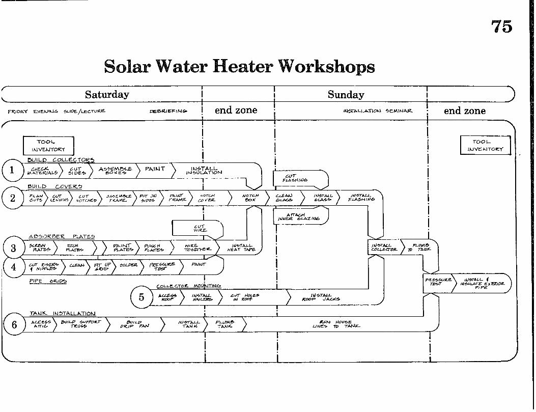
I . IN5TALL
Ik-I5UlATIO~ t
--!---- FIAslIl)6
f Saturday Sunday
I I I I
DEBUlEFINCk i end zone I l%TALLnTlOU 5,elAlhlAR - end zone
AbSORBER PLAl%5 I
?E?s) Fz.!$L IbJ4ThLL !
HEAl- 1bpE I
COUEQ-OEL
0-L \ un- k-E=ER+ LLEluJ f NiWLE4 i PIPE 6RlD5 1 -- COLLE CT-O Ic MO&TIP16
i
I / / / / I I
i . i i
open), and keeping track of checks and money. This person should be on the job before the intial lecture and at least as far into the workshop as noon the first morning.
Introduction, Lecture/Slide Show: We always kick off our hands-on workshop with a lecture/ slide show, usually done t.he evening before the actuai construction begins. First, the teachers and site-owner or tenant are introduced by the sponsor. Then we have a slide show that introduces the reasons for building a solar water heater, gives a broad picture of the history and technology of solar water heating, explains how the system we’ll be bui lding works, and shows step-by-step photos of the work we’1 1 be doing during the next two days. It also gives examples of different installations and freeze protection systems. We will soon have a comprehensive slide show to rent. Contact Ecotope if you are interested.
After the slide show, the plan for the workshop should be presented and participants should sign up for crews. People feel more comfortable
Construction Days: It is important for the teachers to arrive early enough to set up work stations with materials, tools, and electricity where needed. Proceed with the work as outlined. Get building plans to those who are doing installation work. Keep the pace relaxed and the spirit jovial.
In order to bring the point of the workshop home, it is necessary to demonstrate that the technology wcirks. Nothing is more frustrating than to build a collector and not see the proof of the hot pudding. There are two possible workshop demonstrations. One is a temporary hook-up with hoses and a small tank. The other is to complete the permanent collector loop and fill it up, even though it is not plumbed into the house system and the tank housing is not completed.
The demonstration should include a timed experiment with out-flow temperatures noted every five minutes.
Finally, it is important to have a critique and review toward the end of the workshop rather than to let everyone drift off. This should happen in the early afternoon of the last day. It can be a sharing of experiences, ideas and viewpoints,
about this if they know there will be good information exchanges between crews. Reminders about food, clothing, and tools should be given. If the workshop site is different from the lecture site and is hard to find, maps should be made available.
This is also a good time to give a demonstration of copper soldering technique. It is an essential skill for building the system, and everyone should learn how to do it. It also adds a little flash to the evening!
as well as congratul we1 1 done. This is feedback on how well Ecotope did, if you evaluation form can participated to get
ations all around for work also a good opportunity for
you did (and how we at use our manual). An be sent later to those who thoughtful, written comments.
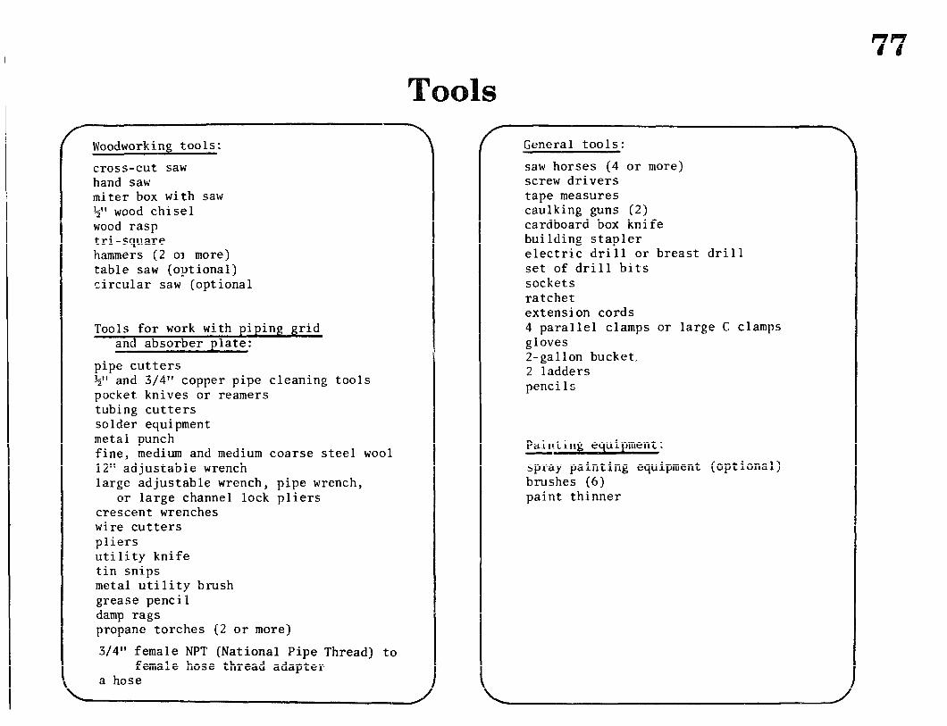
f Woodworking tools:
cross-cut saw hand saw miter box with saw +,I wood chisel wood rasp tri -square hammers (2 03 more) table saw (optional) circular saw (optional
Tools for work with piping grid and absorber plate:
pipe cutters +‘I and 3/4” copper pipe cleaning tools pocket knives or reamers tubing cutters solder equipment metal punch fine, medium and medium coarse steel wool 12” adjustable wrench large adjustable wrench, pipe wrench,
or large channel lock pliers crescent wrenches wire cutters pliers utility knife tin snips metal utility brush grease pencil damp rags propane torches (2 or more)
3/4” female NPT (National Pipe Thread) to female hose thread adapter
a hose
General tools:
saw horses (4 or more) screw drivers tape measures caulking guns (2) cardboard box knife building stapler electric drill or breast drill set of drill bits sockets ratchet extension cords 4 parallel clamps or large C clamps gloves 2-gallon bucket, 2 ladders pencils
Painting equipment:
spray painting equipment (optional) brushes (6) paint thinner
78
Access 2. Differential Thermostats:
Most of the materials listed in this book are available from any good building supply or plumbing supply store. We strongly recommend you sit down with a phone book, go through the Yellow Pages and call around to compare prices and availability. Another thing we’ve found is that retail discount building and plumbing supply stores often end up costing you more because they don’t carry everything you need and they make bulk buying impossible.
In this section you will find clues about tracking down the few items that may not be easy to find. Where we mention specific manufacturers we don’t mean they’re the only sources or even the best ones-- they’re just here to give you a starting place to finding what’s right for you.
1. Demand Water Heaters:
Paloma-- U.S. distributor: John Condon Co. 1103 N. 36th St. Seattle, WA 98103 (206) 632-5600
Junkers- - U.S. distributor: Pressure Cleaning Systems, Inc. 612 N. 16th Ave. Yakima, WA 98902 (509) 452-6607
Many others are listed in Rain,July 1977, p. 12- 15
He1 iotrope General 3733 Itenora Drive Spring Valley, CA 92077
Rho Sigma, Inc. 15150 Raymer St. Van Nuys, CA 91405
3. Filon:
Vistron Corporation 12333 S. Van Ness Ave. Hawthorne, CA 90250 (213) 757-5141
(Seattle sales office) 2150 N. 107th St. Suite 110 Seattle, WA 98133 (206) 362-2700
The local district can refer you to a retailer in your area.
4. Glazier's Tape and Neoprene Sponge:
The tape, Tremco 400 is available from your local sealant supply camp&$. Sponge is available from local gasket, rubber products or packing companies. Be sure to order sponge neoprene! --
5. Thermic Diodes:
Sun of Man Solar Systems Drawer W Bethel Island, CA 94511 (415) 684-3362
6. Pete's Plugs: 10. Solar Water Heater Kits:
R.D. Morse Company 1305 Republican Seattle, WA 98109 (206) 624-4328
R.D. Morse sells these to businesses with a minimum $50 order. We don ‘t know of any retail outlet for them.
7. Pumps:
Grundfos Pumps Corporation 2555 Clovis Ave. Clovis, CA 93612
8. Teflontm Film:
SUN catalog ($2) c/o Solar Usage Now Box 306 Bascom, Ohio 44809
DuPont Company Plastics and Resins Department Wilmington, DE 19898
9. Wood Stove Water Heaters:
Blazing Showers P-0. Box 327 Point Arena, CA 95468
Many stove manufacturers make models especially for their product.
Solar Usage Now Box 306 Bascom, Ohio 44809
Miller and Sun Enterprises P.O. Box 19151 Portland, OR 97219
11. Plans
Other Good Plans for Solar Water Heaters:
Domestic Technology Institute, Workshop Handbook. Evergreen, CO: Domestic Technology Institute, 1977.
Faral lones Urban Center, “Solar Hot Water Heater.” Berkeley, CA: Farallones Institute, no date,
Golder, John, “A Low-Cost Passive -Solar Water Heater.” Santa Cruz, CA: John C. Golder, 1979.
Available from John C. Golder, 304 Morrissey Blvd., Santa Cruz, CA 95062; ask for price. This plan is for a capsule-type water heater costing well under $100 for materials. Collection and storage are combined in one tank, with a reflector and manually-operated& fold-down insulating cover.
Solar Design and Applications, Ltd., Harnessing --- the Sun, Vancouver, B.C.: B.C. Hydro, 1979.
Zomeworks, “Breadbox + Pro Heater Plans.” Albuquerque, NM: Zomeworks Corp., no date.
Zomeworks, “Solar Water Heater, ” Albuquerque, NM: Zomeworks Corp., 1974.
ear eading Anderson, Bruce and Michael Riordan, The Solar Home Book: Heating, Cooling and Designing with the Sun. Harrisville, NH: Cheshire Books, 1976
Excellent chapter on "Solar Water Heating" includes several examples of alternative designs
Fcotope Group, A Preliminary Evaluation of Potential Solar/Conservation Remodel Candidates. Seattle, WA: Ecotope Group, 1977. Prepared for the Office of Conservation, Seattle City Light
Information on how to figure economics and payback
Efficient Use of Energy (The APS Studies on the Technical ASDeCtS of the More Efficient Use of Energy) .
* New York: American Institute of
Physics, 1975 (AIP Conference Proceedings Series; 25)
Technical description of Second Law efficiencies is worthwhile
Godbey, L.C., T.E. Bond, and H.F. Zornig, "Solar and Long Wavelength Energy Transmission of Materials." St. Joseph, MI: American Society of Agricultural Engineers, 1977 (Paper #77-4103)
Lecki, J. et al., Other Homes and Garbage. New York: Scribner's Sons, 1975
See especially sections on "Flat Plate Collectors" and "Hot Water Systems for Domestic Use"
McDaniels, D.K. et al., "Enhanced Solar Energy Collection Using Reflector-Solar Thermal Collector Combinations." Eugene, OR: University of Oregon Physics Department, 1974
Montgomery, Richard H. with Jim Budnick, The Solar Decision Book: Your Guide to Making a Sound Investment. Midland, MI: Dow Corning Carp-, 1978
Use this for further information on active solar systems, but take with a grain of salt all the references to Dow collector fluid
Smith, Robert 0. and John Meeker, "Domestic Hot Water: The New England Electric System Project: A Learning Experience." Solar Age. 3 (3): 16-24, March 1978
Solar Age Catalogue: -- A Guide to Solar Energy Knowledge and Materials. Port Jervis, NJ: Solar -- Vision, Inc., 1377
Includes short articles as well as manufacturers listings
Solar Calculator (44O N Latitude). Eugene, OR: University of Oregon, Center for Environmental Research, 1976
More on sun path charts and solar intensity for different places on the chart
Solar Hot Water and Your Home. Rockville, MD: National Solar Heating and Cooling Information Center, 1977
U.S. Department of Housing and Urban Development, Intermediate Minimum Pronertv Standards for Solar
I .
Heating and Domestic Hot Water Systems, Volume 5. Washington, D.S .: U.S. HUD, 1977 (4930.2)
U.S. Federal Energy Administration, Buying Solar. Washington, D.C .: Superintendent of Documents, U.S. Government Printing Office, 1976 (FEA/G-76/154). Stock # 041-018-00129-4
We welcome your comments on this manual. What could we have done to make it more clear? Are there other things you would like us to have included? We would especially like to know if you have used the manual in building a solar water heater, either by yourself or in a workshop. Let us hear about the details, things you did differently, problems you experienced and their solutions, as well as the things that worked especially well. We are continually working to improve both the workshops and the design of the system, continually learning from our experiences and those of others.
Please write us at:
ECUTUPE, INC. 2812 E. MADISON
SEATTLE. WA 98112 2061322-3753
licotope (;roup is a private non-profit corporation interested in using research and communication to foster the development of renewable energy and appropriate technologies. We maintain a specialized energy resource library in our Seattle office, and are interested in encouraging its use and support by residents of the Pacific Northwest.
Included in the 1 ibrary materials are: --information on solar home design, solar water heating, wind, solar greenhouses, methane, conservation, composting, appropriate technology 9 energy politics and planning; --‘how-to’ plans for composting toilets, solar water heating, solar stills and driers; --periodicals on state-of-the-art for renewable energy, appropriate technology, and alternative networking; --technical handbooks for solar applications and super-conserver building design; and -- information on specific products and manufacturers in solar and other energy technologies.
These materials range from simple, introductory information to technical and theoretical research and applications.
Library staff are usually on hand to suggest materials and answer non-technical questions. Although the library does not lend materials to the public, it is open as a reading room and reference service, and copy facilities are available. Hours are 12 to 6pm on weekdays.
We do our best to answer information requests from residents of the Pacific Northwest by telephone and mai 1. If you have specific questions we’ll be happy to try and answer them, or refer you to a better source. Unfortunately, we do not have any free materials to send out. Please enclose a stamped, self-addressed envelope when you write to us.
All donations made to Ecotope research and education activities are tax-deductible-- and appreciated!
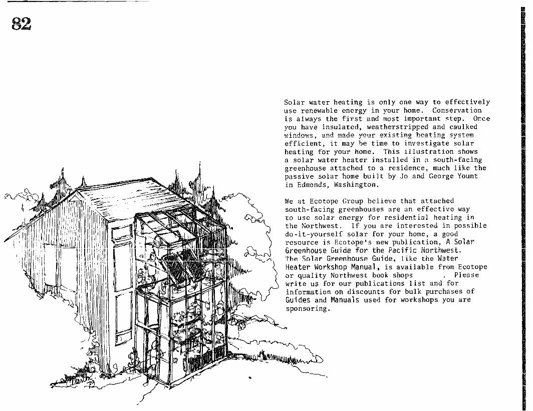
Solar water heating is only one way to effectively use renewable energy in your home. Conservation is always the first and most important step. Orxe you have insulated, weatherstripped and caulked windows, and made your existing heating system efficient, it may be time to investigate solar heating for your home. This illustration shows a solar water heater installed in a south-facing greenhouse attached to a residence, much like the passive solar home built by Jo and George Yount in Edmonds, Washington.
We at Ecotope Group believe that attached south-facing greenhouses are an effective way to use solar energy for residential heating in the Northwest. If you are interested in possible do-it-yourself solar for your home, a good resource is Ecotope’s new publication, A Solar Greenhouse Gujde for the Pacific Northwest. The Solar Greenhouse Guide, like the Water Heater Workshop Manual, is available from Ecotope or quality Northwest book shops . Please write us for our publications list and for information on discounts for bulk purchases of Guides and Manuals used for workshops you are sponsoring.
Solar energy, far from being an exotic science that might solve our increasing energy needs, has been used in the United States for decades as an appropriate technology, one that with individual on-site collection systems directly converts light to heat, and eliminates waste by suiting the energy expended to the job that must be done.
Water heating is second only to space heating as an energy use in the home. This manual has grown from many years of demonstration and experience concerning water heater construction, a "hands on” approach to teaching workshops where solar flat plate collectors are designed to be built and installed by people with general building skills, using available materials at reasonable cost. The system recommended is a passive natural flow system called a thermosiphon, less expensive and complex than an active system because it requires no pumps or controls to make it work. The driving force behind the thermosiphon is convection; colder water in the storage tank sinks to the bottom of the collector panels, and pushes up the warmer water (which is lighter) in the panel to the storage tank,
"Home made" collectors cannot be the ultimate in efficiency and durability, but with care in construction and regular maintenance, as described in this manual, they will last a long time. And by building and installing the water heater yourself, you will save one-half to two-thirds the cost of a high quality commercial system, and still receive three-quarters of the energy the best systems can give you. Plus you'll acquire knowledge and experience you can get no other way.
Ecotope Group knows solar energy works- the hot water in our Seattle office is heated by a solar collector on our roof that we built ourselves. In addition to step-by-step instructions for building, our manual includes sections on siting the system, building codes, material and tools lists, freeze protection, hot water conservation, solar economics, and location and design options. A chapter explains at length how to organize your own hands-on workshops for building collectors, to both create decentralized, sun-powered projects, and also make more people aware of the possibilities for renewable energy.
This second edition is completely revised, and is over twice as long as the original solar hot water heater manual.
A Solar Water Heater Workshop Manual Ecotope Group
.
ECOTOPE, INC. 2812 E. MADISON
S~Tl-LE, WA 98112 ;. ,‘+6/322-3753 _