Embed Size (px)
Citation preview

DIRECTIONAL CONTROLS
21
1.
2.
3.
Specifications
3
3
Specifications
Valve Type
Max. Flow L/min
(U.S.GPM)
Max. Operating Pressure
MPa(PSI)
Max. Pilot Pressure
MPa(PSI)
Min Required
Pilot Pres. MPa(PSI) Ext.Drain Int.Drain
Max. T-Line Back Pressure
MPa(PSI)AC DC R
Max. Change- over Frequency
-1 min (Cycles/Min)Approx.
Mass kg(1bs.)
Model Numbers
DSHG-01-3C∗-∗-13/1380/DSHG-01-2B∗-∗-13/1380/DSHG-03-3C∗-∗-13/1390DSHG-03-2N∗-∗-13/1390DSHG-03-2B∗-∗-13/1390(S-)DSHG-04-3C∗-∗-51/5190(S-)DSHG-04-2N∗-∗-51/5190(S-)DSHG-04-2B∗-∗-51/5190(S-)DSHG-06-3C∗-∗-52/5290(S-)DSHG-06-2N∗-∗-52/5290(S-)DSHG-06-2B∗-∗-52/5290(S-)DSHG-06-3H∗-∗-52/5290(S-)DSHG-10-3C∗-∗-42/4290(S-)DSHG-10-2N∗-∗-42/4290(S-)DSHG-10-2B∗-∗-42/4290(S-)DSHG-10-3H∗-∗-42/4290
40 (10.6)
160 (42.3)
300 (79.3)
500 (132)
1100 (291)
21 (3050)
25 (3630)
31.5 (4570)
31.5 (4570)
31.5 (4570)
21 (3050)
25 (3630)
25 (3630)
25 (3630)
21 (3050)
25 (3630)
21 (3050)
1.0 (150)
0.7 (100)
0.8 (120)
0.8 (120)
1.0 (150)
1.0 (150)
16 (2320)
16 (2320)
21 (3050)
21 (3050)
21 (3050)
16 (2320)
16 (2320)
16 (2320)
16 (2320)
16 (2320)
120
120
120
120
110120100
60
120
120
120
120
110120100
60
120
120
120
120
110100100
50
3.5 (7.7)2.9 (6.4)7.2(15.9)7.2(15.9)6.6(14.6)8.8(19.4)8.8(19.4)8.2(18.1)12.7 (28)12.7 (28)12.1 (27)13.5 (30)45.3(100)45.3(100)44.7 (99)53.1(117)
Standard Type
Shockless Type
Model NumbersRated Flow
L/min (U.S.GPM)Max. Pressure
MPa (PSI)DSHF-10-∗∗∗-∗-27DSHF-16-∗∗∗-∗-37DSHF-24-∗∗∗-∗-28DSHF-32-∗∗∗-∗-27
315 (83)(132)(317)(634)
50012002400
21 (3050)
No.4
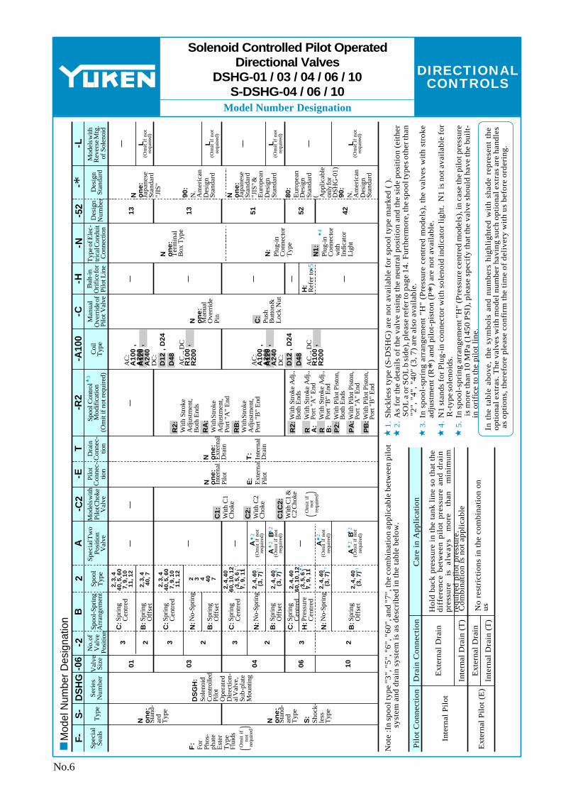
Solenoid Controlled Pilot OperatedDirectional Valves
DSHG-01/03/04/06/10S-DSHG-04/06/10
Sub-plate Mounting
The maximum flow means the limited flow without inducing any abnormality to the operation (changeover) of the valve. For details, please refer to the "List of Standard Models and Maximum Flow" on pages 9 to 13.
In case of internal drain type valve, the differential pressure between pilot pressure and back pressure at tank port should be kept more than the minimum pilot pressure.
The minimum pilot pressure for the valve with pilot piston is 1.8 MPa (260 PSI).
Yuken can offer flanged connection valves described below. Consult Yuken for the details.

DIRECTIONAL CONTROLS
E
Solenoid Ratings / Sub-plates
Valve Type Electric source Coil Type
Frequency (Hz) Source Rating
Voltage (V)Serviceable Range Inrush (A) Holding (A) Power (W)
Current & Power at Rated Voltage
100100110
120
200200220
240
122448
100200
50
60
506050
60
5060
50/60
A100
A120
A200
A240
D12D24D48R100R200
80 - 110
90 - 120
96 - 132108 - 144160 - 220
180 - 240
192 - 264216 - 288
10.8 - 13.221.6 - 26.443.2 - 52.8
90 - 110180 - 220
2.422.142.352.021.781.211.071.181.010.89
0.510.370.440.420.310.250.190.220.210.152.451.230.610.330.16
AC
DC (K Series)
AC DC Rectified (R)
Standard Type
Shockless Type
29
29
Valve Model
Numbers
Japanese Standard "JIS"
Sub-plate Model Numbers
Thread Size
Approx. Mass
kg (1bs.)
Sub-plate Model Numbers
Thread Size
Approx. Mass
kg (1bs.)
European Design Standard
Sub-plate Model Numbers
Thread Size
Approx. Mass
kg (1bs.)
N. American Design Standard
DSGM-01-30DSGM-01X-30DSGM-01Y-30
Rc 1/8
DSGM-03-40DSGM-03X-40DSGM-03Y-40DHGM-03Y-10DHGM-04-20DHGM-04X-20DHGM-06-50DHGM-06X-50DHGM-10-40DHGM-10X-40
Rc 1/4Rc 3/8Rc 3/8Rc 1/2Rc 3/4Rc 3/4Rc 1/2Rc 3/4Rc 3/4Rc 1
Rc 1-1/4Rc 1-1/2
4.7
0.80.80.83.03.0
(10.4)
(1.8)(1.8)(1.8)(6.6)(6.6)
4.7 (10.4)4.4 (9.7)4.1 (9.0)7.4 (16.3)7.4 (16.3)21.5 (47.4)21.5 (47.4)
DSGM-01-3080DSGM-01X-3080
DSGM-03-2180DSGM-03X-2180DSGM-03Y-2180DHGM-03Y-1080DHGM-04-2080DHGM-04X-2080DHGM-06-5080DHGM-06X-5080DHGM-10-4080DHGM-10X-4080
1/8 BSP.F1/4 BSP.F
3/8 BSP.F1/2 BSP.F3/4 BSP.F3/4 BSP.F1/2 BSP.F3/4 BSP.F3/4 BSP.F1 BSP.F
1-1/4 BSP.F1-1/2 BSP.F
0.8 (1.8)0.8 (1.8)
3.0 (6.6)3.0 (6.6)4.7 (10.4)
4.4 (9.7)4.1 (9.0)8.5 (18.7)8.5 (18.7)
4.7 (10.4)
21.5(47.4)21.5(47.4)
DSGM-01-3090DSGM-01X-3090DSGM-01Y-3090DSGM-03-2190DSGM-03X-2190DSGM-03Y-2190DHGM-03Y-1090DHGM-04-2090DHGM-04X-2090DHGM-06-5090DHGM-06X-5090DHGM-10-4090DHGM-10X-4090
1/8 NPT1/4 NPT3/8 NPT3/8 NPT1/2 NPT3/4 NPT3/4 NPT1/2 NPT3/4 NPT3/4 NPT1 NPT
1-1/4 NPT1-1/2 NPT
0.8 (1.8)0.8 (1.8)
3.0 (6.6)3.0 (6.6)4.7 (10.4)
4.4 (9.7)4.1 (9.0)7.4 (16.3)7.4 (16.3)
4.7 (10.4)
21.5 (47.4)21.5 (47.4)
0.8 (1.8)DSHG-01
DSHG-03
DSHG-04
DSHG-06
DSHG-10
→
No.5
Solenoid Controlled Pilot OperatedDirectional Valves
DSHG-01/03/04/06/10S-DSHG-04/06/10
Solenoid Ratings
Inrush current in the above table show rms values at maximum stroke.
The coil type numbers in the shaded column are handled as optional extras. In case these coils are required to be chosen, please confirm the time of delivery with us before ordering.
Sub-plates
DSGM-03∗ is available only for Internal pilot-Internal drain type (Use DHGM-03Y for other valves).Sub-plates are available. Specify the sub-plate model number from the table above. When sub-plates are not used, the mounting surface should have a good machined finish.
CSA Approved Solenoid ValveThe "DSHG" series valve have been approved by the CSA(Candian Standards Association). consult us for details.
DIRECTIONAL CONTROLS
1 1 1 1 1 1
2
22
2
22
54
1. 2. 3. 4. 5.
Model Number Designation
3
F-S
-D
SH
G-0
6-2
B2
A-C
2-E
T-R
2-A
100
-C-H
-N-5
2-L
- ∗D
esig
n St
anda
rdM
odel
s with
R
ever
se M
tg.
of S
olen
oid
Des
ign
Num
ber
Typ
e of E
lec-
tri
cal C
ondu
it
Con
nect
ion
Bul
t-in
Ori
fice
for
Pilo
t Lin
e
Man
ual
Ove
rrid
e of
Pilo
t Val
veC
oil
Typ
eSp
ool C
ontro
l M
odifi
catio
n (O
mit
if n
ot re
quir
ed)
Spec
ial
Seal
sT
ype
Dra
in
Con
nec-
tio
n
Pilo
t C
onne
c-
tion
Mod
els w
ith
Pilo
t Cho
ke
Val
ve
Spec
ial T
wo
Posi
tion
Val
veSp
ool
Typ
eSp
ool-S
prin
g A
rran
gem
ent
No.
of
Val
ve
Posi
tion
Val
ve
Size
Seri
es
Num
ber
F:
For
Phos
-ph
ate
Est
er
Typ
e Fl
uids
N on
e:St
and-
ard
Typ
e
S:
Shoc
k-le
ss
Typ
e
N on
e:St
and-
ard
Typ
e
DS
GH
:So
leno
id
Con
trolle
d Pi
lot
Ope
rate
d D
irec
tion-
al V
alve
, Su
b-pl
ate
Mou
ntin
g
01 03 04 06 10
3 2 3 23 2 3 2
C:S
prin
g C
entr
ed
B:S
prin
g O
ffse
t
N:N
o-Sp
ring
C:S
prin
g C
entr
ed
B:S
prin
g O
ffse
t
N:N
o-Sp
ring
C:S
prin
g C
entr
ed
B:S
prin
g O
ffse
t
N:N
o-Sp
ring
C:S
prin
g C
entr
ed
B:S
prin
g O
ffse
t
H:P
ress
ure
Cen
tred
2, 3
, 4
40, 5
, 60
7,
9, 1
0
11,
12
2, 3
, 4
40,
7
2, 3
, 4
40, 5
, 60
7,
9, 1
0
11,
12 2 3 4 40
7N o
ne:
Inte
rnal
Pi
lot
E:
Ext
erna
l Pi
lot
N on
e:E
xter
nal
Dra
in
T:
Inte
rnal
D
rain
L
(Om
it i
f no
t re
quir
ed)
L
(Om
it i
f no
t re
quir
ed)
L
(Om
it i
f no
t re
quir
ed)
L
(Om
it i
f no
t re
quir
ed)
N on
e:Ja
pane
se
Stan
dard
"J
IS"
90:
N.
Am
eric
an
Des
ign
Stan
dard
N on
e:Ja
pane
se
Stan
dard
"J
IS" &
E
urop
ean
Des
ign
Stan
dard
90:
N.
Am
eric
an
Des
ign
Stan
dard
80:
Eur
opea
n D
esig
n St
anda
rd
( App
licab
le
only
for
DSH
G-0
1)
13 13 51 52 42
N on
e:T
erm
inal
B
ox T
ype
N:
Plug
-in
Con
nect
or T
ype
N1:
Plug
-in
Con
nect
or w
ith
Indi
cato
r L
ight
H:
Ref
er to
N on
e:M
anua
l O
verr
ide
Pin
C:
Push
B
utto
n &
Loc
k N
ut
AC
:A
100
, A
200
A12
0 ,
A24
0D
C:
D12
, D
24D
48A
C→
DC
R10
0 ,
R20
0
AC
:A
100
, A
200
A12
0 ,
A24
0D
C:
D12
, D
24D
48A
C→
DC
R10
0 ,
R20
0
R2:
With
Str
oke
Adj
ustm
ent,
Bot
h E
nds
RA
:W
ith S
trok
e A
djus
tmen
t, Po
rt "
A"
End
RB
:W
ith S
trok
e A
djus
tmen
t, Po
rt "
B"
End
R2:
With
Stro
ke A
dj.,
Bot
h E
nds
R A:
With
Stro
ke A
dj.,
Port
"A
" E
ndR B
:W
ith S
troke
Adj
., Po
rt "
B"
End
P2:
With
Pilo
t Pis
ton,
B
oth
End
sP
A:
PB
:With
Pilo
t Pis
ton,
Po
rt "
A"
End
With
Pilo
t Pis
ton,
Po
rt "
B"
End
Om
it i
f
not
requ
ired
A
B
(O
mit
if
not
requ
ired
)
C1:
With
C1
Cho
ke
C2:
With
C2
Cho
ke
C1C
2:W
ith C
1 &
C2
Cho
ke
Om
it i
f
not
requ
ired
A
(Om
it i
f no
t re
quir
ed)
A
B
(O
mit
if
not
requ
ired
)
2, 4
, 40
60
, 10,
12
3,
5, 6
7,
9,
11
2, 4
, 40
(3
, 7
)
2, 4
, 40
(3
, 7
)
2, 4
, 40
(3
, 7
)
2, 4
, 40
(3
, 7
)
2, 4
, 40
60
, 10,
12
3,
5, 6
7,
9,
11
A
(Om
it i
f no
t re
quir
ed)
Pilo
t Con
nect
ion
Inte
rnal
Pil
ot
Ext
erna
l Pilo
t (E
)
Dra
in C
onne
ctio
n
Ext
erna
l Dra
in
Inte
rnal
Dra
in (
T)
Ext
erna
l Dra
in
Inte
rnal
Dra
in (
T)
Car
e in
App
lica
tion
Hol
d ba
ck p
ress
ure
in th
e ta
nk li
ne s
o th
at th
e di
ffer
ence
bet
wee
n pi
lot
pres
sure
and
dra
in
pres
sure
is
alw
ays
mor
e t
han
m
inim
um
requ
ired
pil
ot p
ress
ure.
Com
bina
tion
is n
ot a
ppli
cabl
e
No
rest
rict
ions
in th
e co
mbi
nati
on o
n us
Solenoid Controlled Pilot OperatedDirectional Valves
No.6
DSHG-01 / 03 / 04 / 06 / 10S-DSHG-04 / 06 / 10
Mod
el N
umbe
r Des
igna
tion
Shc
kles
s ty
pe (
S-D
SH
G)
are
not a
vail
able
for
spo
ol ty
pe m
arke
d (
).
In s
pool
-spr
ing
arra
ngem
ent
"H"
(Pre
ssur
e ce
ntre
d m
odel
s), t
he v
alve
s w
ith
stro
ke
adju
stm
ent (
R∗)
and
pil
ot-p
isto
n (P
∗) a
re n
ot a
vail
able
.N
1 st
ands
for P
lug-
in c
onne
ctor
wit
h so
leno
id in
dica
tor l
ight
. N
1 is
not
ava
ilab
le fo
r R
-typ
e so
leno
ids.
In s
pool
-spr
ing
arra
ngem
ent "
H"
(Pre
ssur
e ce
ntre
d m
odel
s), i
n ca
se th
e pi
lot p
ress
ure
is m
ore
than
10
MP
a (1
450
PS
I), p
leas
e sp
ecif
y th
at th
e va
lve
shou
ld h
ave
the
buil
t-in
ori
fice
to th
e pi
lot l
ine.
Not
e :I
n sp
ool t
ype
"3",
"5"
, "6"
, "60
", a
nd "
7", t
he c
ombi
nati
on a
ppli
cabl
e be
twee
n pi
lot
sys
tem
and
dra
in s
yste
m is
as
desc
ribe
d in
the
tabl
e be
low
.A
s fo
r th
e de
tail
s of
the
valv
e us
ing
the
neut
ral p
osit
ion
and
the
side
pos
itio
n (e
ithe
r S
OL
a o
r SO
L b
side
), p
leas
e re
fer t
o pa
ge 1
4. F
urth
erm
ore,
the
spoo
l typ
es o
ther
than
"2"
, "4"
, "40
" (3
, 7)
are
also
ava
ilab
le.
In t
he t
able
abo
ve,
the
sym
bols
and
num
bers
hig
hlig
hted
wit
h sh
ade
repr
esen
t th
e op
tion
al e
xtra
s. T
he v
alve
s w
ith
mod
el n
umbe
r ha
ving
suc
h op
tion
al e
xtra
s ar
e ha
ndle
s a
s op
tion
s, th
eref
ore
plea
se c
onfi
rm th
e ti
me
of d
eliv
ery
wit
h us
bef
ore
orde
ring
.

DIRECTIONAL CONTROLS
1.
3 1
2
1
2
2.3.
E
Mounting Bolt
Model Numbers Name
Japanese Standard "JIS" European Design Standard N. American Design Standard Qty.
Tightening Torque Nm (in. 1bs.)
Mouting Bolt
Mtg. Bolt Kit
Soc. Hd. Cap Screw
Soc. Hd. Cap Screw
Soc. Hd. Cap ScrewSoc. Hd. Cap Screw
DSHG-01
DSHG-03
(S-)DSHG-04
(S)-DSHG-06(S)-DSHG-10
MBK-01-01-30 MBK-01-02-30M6 × 35 Lg.M6 × 45 Lg. M10 × 50 Lg.M12 × 60 Lg.M20 × 75 Lg.
MBK-01-01-3090 MBK-01-02-3090
1/4-20 UNC × 1-3/4 Lg.1/4-20 UNC × 1-3/4 Lg.
3/8-16 UNC × 2 Lg.1/2-13 UNC × 2-1/2 Lg.
3/4-10 UNC × 3 Lg.
1 set
42 466
5
1212 58
100473
-
-- ---
6
1515 72123585
(43
(104(104 (504(868
(4106
-
-- ---
52)
130)130) 625)1068)5078)
Model NumbersMBK-01-01-30 MBK-01-02-30 MBK-01-01-3090 MBK-01-02-3090
( ( ( (
94 134 94
134
) ) ) )
3.70 5.28 3.70 5.28
A mm (In.) "B" Thd.
M5
No.10-24 UNC
8.5
Dia
.(.3
3)
9(.35)
A
9(.35)
"B" Thd.
9(.35)
15(.59)
4(.16)
"B" Thd. Both Ends
No.7
Solenoid Controlled Pilot OperatedDirectional Valves
DSHG-01/03/04/06/10S-DSHG-04/06/10
For Internal Pilot-Internal Drain.
Mounting Bolt
For External Pilot or External Drain.Mounting bolt kit is common to that of 01 series modular valves. Refer to figure below for the dimensions of bolt kit.
Stud Bolt
NutDIMENSIONS IN
MILLIMETRES (INCHES)

DIRECTIONAL CONTROLS
Options
(.7) (1.1) (1.3) (4.1)
C1, C2 C1C2 P2 PA PB P2 PA
PB
Model with Pilot Choke Adj.
Models with Pilot Piston
Models with Stroke Adj.Model
Numbers
DSHG-03(S-)DSHG-(S-)DSHG-(S-)DSHG-
0.65(1.4)0.65(1.4)0.65(1.4)0.65(1.4)
1.3(2.9)1.3(2.9)1.3(2.9)1.3(2.9)
1.0(2.2)3.6(7.9)
0.5(1.1)1.8(4.0)
0.6(1.3)1.0(2.2)1.2(2.6)3.7(8.2)
0.3 0.5 06
1.85
kg (1bs.)
b a
PY
A B
T
ba
PY
A B
T
A B
P T
a
Y
b
VW
A B
P T
a
Y
b
V
A B
P T
a
Y
b
W
Choke
C2 Choke
C1 Choke
C2 Choke
C1
A B
P TY V X
ba
A B
P T VX
ba
Y
A B
P Tba
Y
A B
P Tba
Y
A B
P Tba
Y
No.8
Solenoid Controlled Pilot OperatedDirectional Valves
DSHG-01/03/04/06/10S-DSHG-04/06/10
Models with Pilot Choke Adjustment
Options
When the adjustment screw is turned clockwise, changeover speed of the main spool becomes slow. In case of the spring centred valves in particular, making slow of the returning speed of the main spool to the neutral position is possible with a C2 choke valve. These choke valves can be used in combination with the valves of spring centred, no-spring, offset, pressure centred and the valves with stroke adjustment.
Models with Pilot Piston(P2, PA, PB)The valves with a pilot piston can be used when the high speed changeover of the main spool is required. However, please not that in case of spring centered valves, there is no change in the returning speed of the main spool to the neutral position even with the pilot piston.
Graphic Symbols (Ex.: Spring Centred)
"PB" Models
Graphic Symbols (Ex.: Spring Centred)
DSHG-01,06,10
DSHG-03, 04
"PA" Models
"P2" Models
Pressure Centred Models (3H∗)The pressure centered type can be used when the returning of the main spool to the neutral position is required to be firmily.
Models with Stroke Adjustment (R2, RA, RB)When the adjustment screw is screwed in , the main spool stroke becomes short and flow rate reduces.
"RB" Models
"RA" Models
"R2" Models
Graphic Symbols (Ex.: Spring Centred)
Graphic Symbols (Ex.: External Pilot-External Drain)
(Only for 3H6, 3H60)
Additional Mass of OptionsAdd the mass described below to the mass of standard models on page 4, if options are required.
Options on Pilot ValveThe same options to DSG-01 series valves are available. Please refer to the Catalogue No. Pub. EC-0402 for the details.

DIRECTIONAL CONTROLS
E
List of Standard Models and Maximum Flow
bA B
P TYP TY
a b
A B
40 (10.6)
40 (10.6)
40 (10.6)
40 (10.6)
40 (10.6)
40 (10.6)
40 (10.6)
40 (10.6)
40 (10.6)
40 (10.6)
40 (10.6)
DSHG-01-3C2
DSHG-01-3C3
DSHG-01-3C4
DSHG-01-
3C40
DSHG-01-3C5
DSHG-01-
3C60
DSHG-01-3C7
DSHG-01-3C9
DSHG-01-
DSHG-01-2B2
DSHG-01-2B3
DSHG-01-2B4
DSHG-01-2B40
DSHG-01-2B7
"2"
"3"
"4"
"40"
"5"
"60"
"7"
"9"
"10"
"11"
"12"
40 (10.6)
40 (10.6)
40 (10.6)
40 (10.6)
40 (10.6)
40 (10.6)
40 (10.6)
40 (10.6)
40 (10.6)
40 (10.6)
40 (10.6)
40 (10.6)
40 (10.6)
40 (10.6)
40 (10.6)
40 (10.6)
40 (10.6)
40 (10.6)
40 (10.6)
40 (10.6)
40 (10.6)
40 (10.6)
40 (10.6)
40 (10.6)
40 (10.6)
40 (10.6)
40 (10.6)
40 (10.6)
40 (10.6)
40 (10.6)
40 (10.6)
40 (10.6)
40 (10.6)
40 (10.6)
40 (10.6) 40 (10.6) 40 (10.6)
7 MPa (1020 PSI)
14 MPa (2030 PSI)
21 MPa (3050 PSI)
7 MPa (1020 PSI)
14 MPa (2030 PSI)
21 MPa (3050 PSI)Model Numbers Model Numbers
Graphic Symbol Graphic SymbolMaximum Flow
L/min (U.S.GPM)Maximum Flow
L/min (U.S.GPM)
Spring Centred Spring Centred
Three Positions Two Positions
Spool Type
No.9
Solenoid Controlled Pilot OperatedDirectional Valves
DSHG-01
A
P T
Bba
Notes ) Max. flow shows value at pilot pressure more than 1 MPa (150 PSI)1.Max. flow in the table above represents the value in the flow condition of P → A → B → T (or P → B → A → T) as shown in the circuit diagram right. In case the valve is used in the condition that either A or B port is blocked, the maximum flow differs according to a hydraulic circuit, therefore, please consult us for details.
2.

DIRECTIONAL CONTROLS
List of Standard Models and Maximum Flow
bA B
P TY
bA B
P TY
a
P TY
a bA B
DSHG-03-2N2
DSHG-03-2N3
DSHG-03-2N4
DSHG-03-
2N40
160 (42.3)
160 (42.3)
160 (42.3)
160 (42.3)
160 (42.3)
DSHG-03-2B2
DSHG-03-2B3
DSHG-03-2B4
DSHG-03-2B40
DSHG-03-2B7
"2"
"3"
"4"
"40"
"7"
160 (42.3)
160 (42.3)
160 (42.3)
160 (42.3)
160 (42.3)
160 (42.3)
160 (42.3)
160 (42.3)
160 (42.3)
160 (42.3)
160 (42.3)
160 (42.3)
160 (42.3)
160 (42.3)
160 (42.3)
7 MPa (1020 PSI)
14 MPa (2030 PSI)
25 MPa (3630 PSI)Model Numbers
Maximum Flow L/min (U.S.GPM)
No-Spring
Spool Type
7 MPa (1020 PSI)
14 MPa (2030 PSI)
25 MPa (3630 PSI)
Maximum Flow L/min (U.S.GPM)
Model Numbers
Graphic Symbol Graphic Symbol
Spring Offset
DSHG-03-3C2
DSHG-03-3C3
DSHG-03-3C4
DSHG-03-
3C40
DSHG-03-3C5
DSHG-03-
3C60
DSHG-03-3C7
DSHG-03-3C9
DSHG-03-
7 MPa (1020 PSI)
14 MPa (2030 PSI)
25 MPa (3630 PSI)Model Numbers
Maximum Flow L/min (U.S.GPM)
Spring Centred
Spool Type
Graphic Symbol
160 (42.3)
160 (42.3)
160 (42.3)
160 (42.3)
160 (42.3)
160 (42.3)
160 (42.3)
160 (42.3)
160 (42.3)
160 (42.3)
160 (42.3)
"2"
"3"
"4"
"40"
"5"
"60"
"7"
"9"
"10"
"11"
"12"
85 160
(22.5) (42.3)
85 160 85
160 85
160 85
160 85
160
(22.5) (42.3) (22.5) (42.3) (22.5) (42.3) (22.5) (42.3) (22.5) (42.3)
85 160 85
160 85
160 85
160 85
160
(22.5) (42.3) (22.5) (42.3) (22.5) (42.3) (22.5) (42.3) (22.5) (42.3)
85 160 85
160 85
160
85 160 85
160 85
160 85
160 85
160
(22.5) (42.3)(22.5) (42.3)(22.5) (42.3)
(22.5) (42.3)(22.5) (42.3)(22.5) (42.3)(22.5) (42.3)(22.5) (42.3)
125 16060 95 60 95 60 95 60 95 60 95
(33.0) (42.3)(15.9) (25.1)(15.9) (25.1)(15.9) (25.1)(15.9) (25.1)(15.9) (25.1)
60 95
(15.9) (25.1)
60 9560 95
(15.9) (25.1)(15.9) (25.1)
60 95
(15.9) (25.1)
160(42.3) 160(42.3)
160(42.3)
No.10
Solenoid Controlled Pilot OperatedDirectional Valves
DSHG-03
Three Positions
Two Positions
A
P T
Bba
85 (22.5)160 (42.3)
160 (42.3)
Notes:
The relation between max. flow and pilot pressure in the table above is as shown below.
1.
2.
(Example)
Maximum flow rate is constant regardless of pilot pressure. Pilot Pressure more than 0.7 MPa (100 PSI).
Pilot Pressure at 0.7 MPa (100 PSI).
Pilot Pressure at 1 MPa (150 PSI).
Max. flow in the table above represents the value in the flow condition of P → A → B → T (or P → B → A → T) as shown in the circuit diagram right. In case the valve is used in the condition that either A or B port is blocked, the maximum flow differs according to a hydraulic circuit, therefore, please consult us for details.

DIRECTIONAL CONTROLS
E
List of Standard Models and Maximum Flow
bA B
P TY
a bA B
P TY
P TY
a bA B
DSHG-04-2N2
DSHG-04-2N3
DSHG-04-2N4
DSHG-04-
2N40
DSHG-04-2B2
DSHG-04-2B3
DSHG-04-2B4
DSHG-04-2B40
DSHG-04-2B7
"2"
"3"
"4"
"40"
"7"
300 (79.3)
300 (79.3)
300 (79.3)
300 (79.3)
300 (79.3)
Maximum Flow L/min (U.S.GPM)
No-Spring
Spool Type
Model Numbers
(S-)
(S-)
(S-)
(S-)
(S-)
(S-)
Model Numbers
Graphic Symbol
10 MPa (1450 PSI)
16 MPa (2320 PSI)
25 MPa (3630 PSI)
31.5 MPa (4570 PSI)
Maximum Flow L/min (U.S.GPM)
Spring Offset
300 (79.3)
300 (79.3)
300 (79.3)
300 (79.3)
300 (79.3)
300 (79.3)
300 (79.3)
300 (79.3)
300 (79.3)
300 (79.3)
300 (79.3)
300 (79.3)
300 (79.3)
300 (79.3)
300 (79.3)
300 (79.3)
300 (79.3)
300 (79.3)
300 (79.3)
300 (79.3)
300 (79.3)
300 (79.3)
300 (79.3)
300 (79.3)
300 (79.3)
300 (79.3)
300 (79.3)
300 (79.3)
300 (79.3)
300 (79.3)
300 (79.3)
300 (79.3)
300 (79.3)
300 (79.3)
300 (79.3)
"2"
"3"
"4"
"40"
"5"
"6"
"60"
"7"
"9"
"10"
"11"
"12"
Model Numbers
Maximum Flow L/min (U.S.GPM)Spool Type
Graphic Symbol
Spring Centred
10 MPa (1450 PSI)
16 MPa (2320 PSI)
25 MPa (3630 PSI)
31.5 MPa (4570 PSI)
10 MPa (1450 PSI)
16 MPa (2320 PSI)
25 MPa (3630 PSI)
31.5 MPa (4570 PSI)
(S-)DSHG-04-3C2 DSHG-04-3C2
(S-)
(S-)
DSHG-04-3C4 DSHG-04-3C4 DSHG-04-3C40
DSHG-04-3C3
DSHG-04-3C5
DSHG-04-3C6
(S-)DSHG-04-3C60
DSHG-04-3C7
DSHG-04-3C9
(S-)DSHG-04-3C10
(S-)DSHG-04-3C12
DSHG-04-3C11
300 (79.3) 300 (79.3)
300 (79.3) 300 (79.3)300 (79.3) 300 (79.3)
300 (79.3)
250 (66.1)
300 (79.3)
300 (79.3)
300 (79.3)
300 (79.3)
300 (79.3) 300 (79.3)
300 (79.3) 300 (79.3)
300 (79.3)
300 (79.3)
300 (79.3)
300 (79.3)
300 (79.3)300 (79.3)300 (79.3)
250 (66.1)
300 (79.3) 300 (79.3)300 (79.3) 250 (66.1)
250 (66.1) 140 (37.0)200 (52.8) 120 (31.7)
165 (43.6) 110 (29.1) 145 (38.3) 110 (29.1)
260 (68.7)
245 (64.7)245 (64.7)
245 (64.7)
300 (79.3)300 (79.3)
235 (62.1)
200 (52.8)145 (38.3)
250 (66.1)280 (74.0)
260 (68.7)160 (42.3)140 (37.0)
280 (74.0) 250 (66.1)
170 (44.9) 120 (31.7)
135 (35.7) 110 (29.1)
300 (79.3) 250 (66.1)
200 (52.8) 120 (31.7)
150 (39.6) 110 (29.1)
300 (79.3) 250 (66.1)
200 (52.8) 120 (31.7)
145 (38.3) 110 (29.1)
Graphic Symbol
No.11
Solenoid Controlled Pilot OperatedDirectional Valves
DSHG-04 / S-DSHG-04
Notes: Max flow described above shown value at pilot pressure more than 0.8 MPa (120 PSI).1.
A
P T
Bba
Two Positions
Three Positions
Max. flow in the table above represents the value in the flow condition of P → A → B → T (or P → B → A → T) as shown in the circuit diagram right. In case the valve is used in the condition that either A or B port is blocked, the maximum flow differs according to a hydraulic circuit, therefore, please consult us for details.
2.

DIRECTIONAL CONTROLS
List of Standard Models and Maximum Flow
bA B
P TY
a bA B
P TY
P TY
a bA B
P TY
a bA B
V
"2"
"3"
"4"
"40"
"7"
Maximum Flow L/min (U.S.GPM)
No-Spring
Spool Type
Graphic Symbol
DSHG-06-2N2
DSHG-06-2N3
DSHG-06-2N4
DSHG-06-
2N40
500 (132)
500 (132)
500 (132)
500 (132)
500 (132)
(S-)
(S-)
(S-)
Model Numbers 10 MPa (1450 PSI)
16 MPa (2320 PSI)
25 MPa (3630 PSI)
31.5 MPa (4570 PSI)
DSHG-06-2B2
DSHG-06-2B3
DSHG-06-2B4
DSHG-06-2B40
DSHG-06-2B7
Model Numbers
(S-)
(S-)
(S-)
Maximum Flow L/min (U.S.GPM)
Spring Offset
10 MPa (1450 PSI)
16 MPa (2320 PSI)
25 MPa (3630 PSI)
31.5 MPa (4570 PSI)
Graphic Symbol
"2"
"3"
"4"
"40"
"5"
"6"
"60"
"7"
"9"
"10"
"11"
"12"
Model Numbers
Maximum Flow L/min (U.S.GPM)Spool Type
Graphic SymbolSpring Centred
10 MPa (1450 PSI)
16 MPa (2320 PSI)
25 MPa (3630 PSI)
31.5 MPa (4570 PSI)
(S-)DSHG-06-3C2
DSHG-06-3C3
DSHG-06-3C4
DSHG-06-
3C40
DSHG-06-3C5
DSHG-06-3C6
DSHG-06-
3C60
DSHG-06-3C7
DSHG-06-3C9
DSHG-06-
500 (132)
500 (132)
500 (132)
500 (132)
500 (132)
500 (132)
500 (132)
500 (132)
500 (132)
500 (132)
500 (132)
500 (132)
500 (132)
500 (132)
500 (132)
500 (132)
500 (132)
500 (132)
500 (132)
500 (132)
500 (132)
500 (132)
500 (132)
500 (132)
500 (132)
500 (132)
500 (132)
500 (132)
500 (132)
500 (132)
500 (132)
500 (132)
500 (132)
500 (132)
500 (132)
10 MPa (1450 PSI)
16 MPa (2320 PSI)
25 MPa (3630 PSI)
31.5 MPa (4570 PSI)Model Numbers
Maximum Flow L/min (U.S.GPM)
Graphic SymbolPressure Centred
(S-)
(S-)
(S-)
(S-)
(S-)
(S-)DSHG-06-3H2
DSHG-06-3H3
DSHG-06-3H4
DSHG-06-
3H40
DSHG-06-3H5
DSHG-06-3H6
DSHG-06-
3H60
DSHG-06-3H7
DSHG-06-3H9
DSHG-06-
(S-)
(S-)
(S-)
(S-)
(S-)
500 (132)
500 (132)
500 (132)
500 (132)
500 (132)
475 (125)
475 (125)
500 (132)
500 (132)
500 (132)
500 (132)
500 (132)
500 (132)
500 (132)
500 (132)
500 (132)
500 (132)
390 (103)
420 (111)
500 (132)
500 (132)
500 (132)
500 (132)
500 (132)
500 (132)
500 (132)
500 (132)
500 (132)
500 (132)
500 (132)
500 (132)
500 (132)
500 (132)
500 (132)
500 (132)
500 (132)
500 (132)
500 (132)
500 (132)
500 (132)
500 (132)
500 (132)
500 (132)
500 (132)
500 (132)
500 (132)
500 (132)
500 (132)
500 (132)
500 (132)
500 (132)
500 (132)
500 (132)
500 (132)
500 (132)
500 (132)
500 (132)
500 (132)
500 (132)
500 (132)
425 (112)
300 (79.3)
340 (89.8)
450 (119)
350 (92.5)
230 (60.8)
280 (74.0)
360 (95.1)
460 (122) 370 (97.8) 500 (132)
500 (132)
500 (132)
410 (108) 500 (132)
310 (81.9) 500 (132)
310 (81.9) 500 (132) 310 (81.9) 500 (132)
410 (108) 500 (132)410 (108) 500 (132)
450 (119) 500 (132) 410 (108) 500 (132) 410 (108) 500 (132) 410 (108) 500 (132)
360 (95.1) 500 (132) 310 (81.9) 500 (132) 310 (81.9) 500 (132) 310 (81.9) 500 (132)
460 (122) 500 (132) 460 (122) 500 (132) 460 (122) 500 (132)
420 (111) 500 (132) 420 (111) 500 (132) 470 (124) 500 (132) 420 (111) 500 (132) 420 (111) 500 (132)
420 (111) 500 (132)
No.12
Solenoid Controlled Pilot OperatedDirectional Valves
DSHG-06 / S-DSHG-06
A
P T
Bba
410 (108)500 (132)
500 (132)
Notes:
The relation between max. flow and pilot pressure in the table above is as shown below.
1.
2.
(Example)
Maximum flow rate is constant regardless of pilot pressure. Pilot Pressure more than 0.8 MPa (120 PSI). In case pressure centred models, pilot pressure is more than 1 MPa (150 PSI).
Pilot Pressure at 0.8 MPa (120 PSI). In case pressure centred models, pilot pressure is more than 1 MPa (150 PSI)
Pilot Pressure at 1.5 MPa (220 PSI).
Two Positions
Three Positions
Max. flow in the table above represents the value in the flow condition of P → A → B → T (or P → B → A → T) as shown in the circuit diagram right. In case the valve is used in the condition that either A or B port is blocked, the maximum flow differs according to a hydraulic circuit, therefore, please consult us for details.

DIRECTIONAL CONTROLS
E
List of Standard Models and Maximum Flow
Two Positions
bA B
P TY
a bA B
P TY
P TY
a bA B
P TY
a bA B
V
Model Numbers
Maximum Flow L/min (U.S.GPM)Spool Type
Graphic SymbolSpring Centred
10 MPa (1450 PSI)
16 MPa (2320 PSI)
25 MPa (3630 PSI)
31.5 MPa (4570 PSI)
16 MPa (2320 PSI)
25 MPa (3630 PSI)
31.5 MPa (4570 PSI)Model Numbers
Maximum Flow L/min (U.S.GPM)
Graphic SymbolPressure Centred
"2"
"3"
"4"
"40"
"5"
"6"
"60"
"7"
"9"
"10"
"11"
"12"
(S-)DSHG-10-3C2
DSHG-10-3C3
DSHG-10-3C4
DSHG-10-
3C40
DSHG-10-3C5
DSHG-10-3C6
DSHG-10-
3C60
DSHG-10-3C7
DSHG-10-3C9
DSHG-10-
(S-)
(S-)
(S-)
(S-)
(S-)
1100 (291)
1100 (291)
1100 (291)
1100 (291)
1100 (291)
1050 (277)
1050 (277)
1100 (291)
1100 (291)
1100 (291)
1100 (291)
1100 (291)
(S-)DSHG-10-3H2
DSHG-10-3H3
DSHG-10-3H4
DSHG-10-
3H40
DSHG-10-3H5
DSHG-10-3H6
DSHG-10-
3H60
DSHG-10-3H7
DSHG-10-3H9
DSHG-10-
(S-)
(S-)
(S-)
(S-)
(S-)
950 (251) 1100 (291)
"2"
"3"
"4"
"40"
"7"
Maximum Flow L/min (U.S.GPM)
No-Spring
Spool Type
Graphic Symbol
DSHG-10-2N2
DSHG-10-2N3
DSHG-10-2N4
DSHG-10-
2N40
(S-)
(S-)
(S-)
Model Numbers 16 MPa (2320 PSI)
25 MPa (3630 PSI)
31.5 MPa (4570 PSI)
DSHG-10-2B2
DSHG-10-2B3
DSHG-10-2B4
DSHG-10-2B40
DSHG-10-2B7
Model Numbers
(S-)
(S-)
(S-)
Maximum Flow L/min (U.S.GPM)
Spring Offset
16 MPa (2320 PSI)
25 MPa (3630 PSI)
31.5 MPa (4570 PSI)
Graphic Symbol
10 MPa (1450 PSI)
1100 (291)
1100 (291)
1100 (291)
1100 (291)
1100 (291)
880 (232)
940 (248)
1100 (291)
1100 (291)
1100 (291)
1100 (291)
1100 (291)
1100 (291)
1100 (291)
1100 (291)
1100 (291)
1100 (291)
1100 (291)
1100 (291)
1100 (291)
1100 (291)
1100 (291)
1100 (291)
1100 (291)
1100 (291)
1100 (291)
1100 (291)
1100 (291)
1100 (291)
1100 (291)
1100 (291)
1100 (291)
1100 (291)
1100 (291)
1100 (291)
1100 (291)
1100 (291)
1100 (291)
1100 (291)
1100 (291)
1100 (291)
1100 (291)
1100 (291)
1100 (291)
1100 (291)
1100 (291)
1100 (291)
1100 (291)
750 (198) 1100 (291)
1060 (280) 895 (236)
950 (251) 1100 (291) 950 (251) 1100 (291)
750 (198) 1100 (291) 750 (198) 1100 (291)
980 (259)
700 (185)
785 (207)
850 (225)
570 (151)
680 (180)
1040 (275) 1100 (291)
870 (230) 1100 (291)
950 (251) 1100 (291) 950 (251) 1100 (291) 950 (251) 1100 (291)
1040 (275) 870 (230)
750 (198) 1100 (291) 750 (198) 1100 (291) 750 (198) 1100 (291)
1060 (280) 1100 (291) 1060 (280) 1100 (291) 1060 (280) 1100 (291)
1100 (291)
1100 (291)
970 (256) 1100 (291) 1050 (277) 1100 (291) 970 (256) 1100 (291) 970 (256) 1100 (291) 1000 (264) 1100 (291) 970 (256) 1100 (291) 970 (256) 1100 (291)
10 MPa (1450 PSI)
10 MPa (1450 PSI)
1100 (291)
1100 (291)
1100 (291)
1100 (291)
1100 (291)
1100 (291)
1100 (291)
1100 (291)
1100 (291)
1100 (291)
1100 (291)
1100 (291)
1100 (291)
1100 (291)
1100 (291)
1100 (291)
1100 (291)
1100 (291)
1100 (291)
1100 (291)
1100 (291)
1100 (291)
1100 (291)
1100 (291)
1100 (291)
1100 (291)
1100 (291)
1100 (291)
1100 (291)
1100 (291)
1100 (291)
1100 (291)
1100 (291)
1100 (291)
1100 (291)
1100 (291)
1100 (291)
1100 (291)
1100 (291)
1100 (291)
No.13
Solenoid Controlled Pilot OperatedDirectional Valves
DSHG-10 / S-DSHG-10
A
P T
Bba
1040 (275)1100 (291)
1100 (291)
Notes ) The relation between max. flow and pilot pressure in the table above is as shown below.
1.
2.
(Example)
Maximum flow rate is constant regardless of pilot pressure. Pilot Pressure more than 1 MPa (150 PSI).
Pilot Pressure at 1 MPa (150 PSI).
Pilot Pressure at 1.5 MPa (220 PSI).
Three Positions
Max. flow in the table above represents the value in the flow condition of P → A → B → T (or P → B → A → T) as shown in the circuit diagram right. In case the valve is used in the condition that either A or B port is blocked, the maximum flow differs according to a hydraulic circuit, therefore, please consult us for details.

DIRECTIONAL CONTROLS
Reverse Mtg. of Sol. / Special 2-Position Valve
A B
TPY
bBA
P T Y
aA B
TPY
bBA
P T Y
a a b
Y P T
A B
Standard Mtg.
Reverse Mtg. Type
Standard Mtg.
Reverse Mtg. Type
Standard Mtg.
Graphic Symbols Graphic Symbols Graphic Symbols
Model Numbers Model Numbers Model Numbers
04 06 10
DSHG- -2B∗A
04 06 10
DSHG- -2B∗B
04 06 10
DSHG- -2N∗A
DSHG-∗-2B2A(S-)
DSHG-∗-2B3A
DSHG-∗-2B4A(S-)
DSHG-∗-2B40A(S-)
DSHG-∗-2B5A
DSHG-∗-2B6A
DSHG-∗-2B60A(S-)
DSHG-∗-2B7A
DSHG-∗-2B9A
DSHG-∗-2B10A(S-)
DSHG-∗-2B11A
DSHG-∗-2B12A(S-)
DSHG-∗-2B2B(S-)
DSHG-∗-2B3B
DSHG-∗-2B4B(S-)
DSHG-∗-2B40B(S-)
DSHG-∗-2B5B
DSHG-∗-2B6B
DSHG-∗-2B60B(S-)
DSHG-∗-2B7B
DSHG-∗-2B9B
DSHG-∗-2B10B(S-)
DSHG-∗-2B11B
DSHG-∗-2B12B(S-)
DSHG-∗-2N2A(S-)
DSHG-∗-2N3A
DSHG-∗-2N4A(S-)
DSHG-∗-2N40A
(S-)
DSHG-∗-2N5A
DSHG-∗-2N6A
DSHG-∗-2N60A(S-)
DSHG-∗-2N7A
DSHG-∗-2N9A
DSHG-∗-2N10A(S-)
DSHG-∗-2N11ADSHG-∗-2N12A(S-)
Y P T
A Bb
YTP
BAa
SOL b SOL a
Standard Mtg. of Solenoid Reverse Mtg. of Solenoid ("L")
No.14
Solenoid Controlled Pilot OperatedDirectional Valves
DSHG-01 / 03 / 04 / 06 / 10S-DSHG-04 / 06 / 10
A B
P T
a b
Y
A B
PY T
bA B
Y P T
b
2B2A 2B2B
(Example) In case of Spool Type "2"
"A": Use of Neutral and SOL. a Energised Position
SOL. a Energised Position
SOL. b Energised Position
Neutral Position
"B": Use of Neutral and SOL. b Energised Position
Valves Using Neutral Position and Side Position. (Special Two position Valve)Besides the use of the standard 2-position valves aforementioned in the "List of Standard Models and Maximum Flow", the 3-position valves also can be used as the 2-position valves using the two of their three positions. In this case, there are two kinds of the valve available. One is the valve using the neutral position and SOL a position (2B∗A) and another is the valve using the neutral position and SOL b position (2B∗B).
Reverse Mounting of Solenoid.In spring offset type, it is a standard configuration that the solenoid is mounted onto the valve in the SOL b position (side). However, in this particular spool-spring arrangement, the mounting of the solenoid onto the valve in the reverse position - SOL a side - is also available. The graphic symbol for this reverse mounting is as shown below. As for the valve type 2B∗A and 2B∗B, please refer to the explanation under the heading of "Valves Using NeutralPosition and Side Position" given below.

DIRECTIONAL CONTROLS
E
Preessure Drop
Spool Type
P A→ B T→ P B→ A T→ P T→
Pressure Drop Curve Numbers Spool
TypeP A→ B T→ P B→ A T→ P T→
Pressure Drop Curve Numbers
3
4
3
33
3
2
2
2
22
2
3
4
3
33
3
2
1
1
3
4
3
33
2
2
2
22
3
4
3
33
2
2
2
22
234
405
60
79
101112
2
2
2
22
2
Spool Type
P A→ B T→ P B→ A T→ P T→
Pressure Drop Curve Numbers Spool
TypeP A→ B T→ P B→ A T→ P T→
Pressure Drop Curve Numbers
3
5
33
6
3
3
5
53
3
3
4
5
44
4
4
4
2
1
3
6
36
3
3
3
53
3
4
6
44
4
4
4
44
6
234
405
60
79
101112
4
6
64
6
4
Spool Type
P A→ B T→ P B→ A T→ P T→
Pressure Drop Curve Numbers Spool
TypeP A→ B T→ P B→ A T→ P T→
Pressure Drop Curve Numbers
5
5
5
57
5
4
3
3
44
3
5
7
5
1
7
5
5
56
5
4
4
24
7
5
5
55
7
6
6
66
234
4056
79
101112
Spool Type
P A→ B T→ P B→ A T→ P T→
Pressure Drop Curve Numbers Spool
TypeP A→ B T→ P B→ A T→ P T→
Pressure Drop Curve Numbers
2
2
2
2
3
4
2
2
2
6
2
2
4
2
2
6
2
2
7
4
5
24
40
601012
4
5
6
605
5
55
5
6
5
5
65
6 5 4 5 5
2
2
MPaPSI
Pre
ssur
e D
rop
P
L /min
U.S.GPMFlow Rate
1
2
3
4
0 10 20 30 40
1.4
1.2
0.8
0.4
1.0
0.6
0.20
200
160
120
80
40
0
2 4 6 8 100
MPaPSI
Pre
ssur
e D
rop
P
L /min
U.S.GPMFlow Rate
40 80 120 160
2.0
1.6
1.2
0.8
0.4
300
0
10 20 30 400
0
3
456
21
250
200
150
100
50
0
MPaPSI
Pre
ssur
e D
rop
P
L /min
U.S.GPMFlow Rate
180
0
20 40 60 800
160
120
80
40
No.15
Solenoid Controlled Pilot OperatedDirectional Valves
DSHG-01/03/04S-DSHG-04
2 Pressure drop curves based on viscosity of 35 mm /s (164 SSU) and specific gravity of 0.850.
12 3
4
5
6
7
0 100 150 20050 250 300
1.2
0.8
0.4
DSHG-01
DSHG-03
DSHG-04, S-DSHG-04
0
DSHG-01
DSHG-03
DSHG-04
S-DSHG-04

DIRECTIONAL CONTROLS
Pressure Drop
Spool Type
P A→ B T→ P B→ A T→ P T→
Pressure Drop Curve Numbers Spool
TypeP A→ B T→ P B→ A T→ P T→
Pressure Drop Curve Numbers
8
6
8
8
8
5
5
4
5
5
4
3
8
6
8
8
5
5
4
1
1
6
6
6
8
8
5
4
5
5
4
6
6
6
8
5
7234
4056
79
101112
7 60
8 5 8
1
7
7
7
7
4
7
7
7
7
7
Spool Type
P A→ B T→ P B→ A T→ P T→
Pressure Drop Curve Numbers Spool
TypeP A→ B T→ P B→ A T→ P T→
Pressure Drop Curve Numbers
66
8
12
5
66
8
68
8
25
5
68
8
324
401012
2 60 12
7
7
7
Spool Type
P A→ B T→ P B→ A T→ P T→
Pressure Drop Curve Numbers Spool
TypeP A→ B T→ P B→ A T→ P T→
Pressure Drop Curve Numbers
9
7
9
99
5
6
6
6
66
3
9
7
9
98
5
5
1
2
8
7
7
99
5
6
6
56
8
7
7
98
5234
4056
79
101112
8 60
9 7 9
3
7
6
86
2
7
8
87
6
Spool Type
P A→ B T→ P B→ A T→ P T→
Pressure Drop Curve Numbers Spool
TypeP A→ B T→ P B→ A T→ P T→
Pressure Drop Curve Numbers
8
8
9
3
5
6
8
8
9
8
9
9
4
5
7
8
9
9
424
401012
4 60 2
6
8
8
6
ViscositySSU
Factor 0.81 0.87 0.96 1.03 1.09 1.14 1.19 1.2377 98 141 186 232 278 324 371
2 mm /s 15 20 30 40 50 60 70 80
1.2741790
1.30464100
1 2
3
4
5
67
8
9
0 200 400 600 800
2.0
1.6
1.2
0.8
0.4
12
3
4
5
6
7
8
0100 200 300 400 500
2.0
1.6
1.2
0.8
0.4
PSI
Pre
ssur
e D
rop
P
L /min
U.S.GPMFlow Rate
300
250
200
150
50
0
20 60 80 100 1200
0
14040
100
MPa
1000 1100
PSI
Pre
ssur
e D
rop
P
L /min
U.S.GPMFlow Rate
300
250
200
150
50
0
50 1500 300100
100
MPa
200 250
0
No.16
Solenoid Controlled Pilot OperatedDirectional Valves
DSHG-06, 10 / S-DSHG-06, 10
DSHG-06, S-DSHG-06
DSHG-10, S-DSHG-10
DSHG-06
S-DSHG-06
DSHG-10
S-DSHG-10
For any other viscosity, multiply the factors in the table below.
For any other specific gravity (G'), the pressure drop ( P') may be obtained from the formula right.
P' = P(G'/0.850)

DIRECTIONAL CONTROLS
E
Typical Changeover Time
Pilot Pressure
SOL"OFF"SOL"ON"
3C∗
SOL"ON","OFF"2B∗
2N∗
250
200
150
100
50
5 10 15 20 25
SOL"OFF"SOL"ON"3C∗
2N∗ SOL"ON"2B∗SOL"OFF"
150
100
50
5 10 15 20 25
SOL"OFF"SOL"ON"3C∗
2N∗ SOL"ON"2B∗SOL"OFF"
150
100
50
5 10 15 20 25
30002000100003600
MPa
PSI
ms
Cha
ngeo
ver T
ime
00
Pilot Pressure
30002000100003600
MPa
PSI
ms
Cha
ngeo
ver T
ime
00
Pilot Pressure
30002000100003600
MPa
PSI
Cha
ngeo
ver T
ime
00
ms
No.17
Solenoid Controlled Pilot OperatedDirectional Valves
DSHG-04/06/10
Changeover time varies according to oil viscosity, spool type and hydraulic circuit.
DSHG-04
Test ConditionsCoil Type : D∗(Models with DC solenoids) Voltage : Rated Voltage
2 Oil Viscosity : 35 mm /s (164 SSU)
DSHG-10
DSHG-06

DIRECTIONAL CONTROLS
Mounting surface: ISO 4401-AB-03-4-A
Installation Drawing
Sub-plate Model Numbers
DSGM-01-30DSGM-01-3080DSGM-01-3090DSGM-01X-30DSGM-01X-3080DSGM-01X-3090DSGM-01Y-30DSGM-01Y-3090
Piping Size "C" Thd.Rc 1/8
1/8 NPTRc 1/4
Rc 3/8
1/4 BSP.F1/4 NPT
3/8 NPT
"D" Thd.
M5
No. 10-24 UNC
M5
No. 10-24 UNCM5
No. 10-24 UNC
"E" mm (IN.)
10 (.39)
12 (.47)
10 (.39)
12 (.47)10 (.39)12 (.47)
1/8 BSP.F
Model Numbers
DSHG-01-∗∗∗-∗-13 DSHG-01-∗∗∗-∗-
"C" Thd.
G 1/2 1/2 NPT
Rc 1/4 1/4 NPT
"D" Thd.
A
T
P
B
SOL b SOL a
SOL b SOL a
12.7(.50)
30.2 (1.19)
40.5 (1.59)
14.2 (.56)
0.75
(.0
3)15
.5
(.61)
8.5
(.33)
7.5
(.30)
7 (.28) Dia. 4 Places
"D" Thd. "E" Deep 4 Places
21.5 (.85)
5.2
(.20)
25.8
(1
.02)
31
(1.2
2)31
.75
(1.2
5) 48
(1.8
9)63
(2
.48)
71 (2.80)
85 (3.35)
7 (.28)
7 (.28) Dia. Through 11 (.43) Dia. Spotface 2 Places
15 (.59)
16 (.63)
32 (1.26)
11
(.43)
24
(.94)37
(1
.46)
12.5 (.49)
35.5 (1.40)
58.5 (2.30)
"C" Thd. 4 Places
40.5(1.59)
Space Needed to Remove Solenoid-Each End
AC : DC,R :
45.5 (1.79) 55 (2.17)
Cylinder Port "B"
Pressure Port "P"
Cylinder Port "A"AC : DC,R :
191.4 (7.54) 210 (8.27)
AC : DC,R :
74.2 (2.92) 83.5 (3.29)
Tank Port "T"Solenoid Indicator Light
31(1
.22)
32.5
(1.2
8)
130.
3(5
.13)
Manual Actuator 6(.24) Dia.
48(1.89)
112
(4.4
1)78
(3.0
7)65
(2.5
6)
43.5(1.71)
125(4.92)
AC : DC,R :
158.2 (6.23) 167.5 (6.59)
Electrical Conduit Connection "C" Thd. (Both Ends)
90(3.54)
0.5(.02)
0.75
(.03)
Double Solenoid Models Only
Mounting Surface (O-Rings Furnished)
Pilot Drain Port "Y" "D" Thd.
Pilot Pressure Port "X" "D" Thd.
60(2
.36)
105
(4.1
3)118
(4.6
5)
152
(5.9
8)
170.
3(6
.70)
No.18
Solenoid Controlled Pilot OperatedDirectional Valves
DSHG-01
Sub- plates
Terminal Box type: DSHG-01-∗∗∗-∗-13/1390Internal Pilot - Internal Drain External Pilot - External Drain
External Pilot - Internal DrainInternal Pilot - External Drain
For other dimensions, refer to "Internal Pilot Internal Drain".
DIMENSIONS IN MILLIMETRES (INCHES)
DSGM-01∗-30/3080/3090

DIRECTIONAL CONTROLS
E
Mounting surface: ISO 4401-AB-03-4-A
Installation Drawing
Model Numbers
DSHG-01-∗∗∗-∗-N∗-13 DSHG-01-∗∗∗-∗-N∗-1380
"J" Thd.
Rc 1/4 1/4 BSP.F 1/4 NPT
Model NumbersDimensions mm (Inches)
C D E F H J L
130 (5.12)
141 (5.55) 144 (5.67)
53 (2.09)
64 (2.52) 57.2 (2.25)
27.5 (1.08)
27.5 (1.08) 34 (1.34)
39 (1.54)
39 (1.54) 53 (2.09)
170 (6.69)
181 (7.13) 184 (7.24)
74.2 (2.92)
83.5 (3.29)
191.4 (7.54) 158.2 (6.23)
210 (8.27) 167.5 (6.59)
DSHG-01-∗∗∗-∗-A∗-N/
N1 DSHG-01-∗∗∗-∗-D∗-N/
K
SOL aSOL b
SOL aSOL b
Pilot Pressure Port "X" "J" Thd.
Pilot Drain Port "Y" "J" Thd.
60(2
.36)
118
(4.6
5)
L
D10
5(4
.13)
D65
(2.5
6)
C
48(1.89)
EH
F 27(1.06) (2.76)
70
78(3
.07)
43.5(1.71)
125(4.92)
K
J
Cable Departure Cable Applicable: Outside Dia. ⋅⋅⋅⋅⋅⋅ 8-10mm(.31-.39 IN.) Conductor Area ⋅⋅⋅⋅⋅⋅Not Exceeding 2 1.5mm (.002 Sq. IN.)
The position of the Plug-in connector can be changed as illustrated below by loosening the lock nut. After completion of the change, be sure to tighten the lock nut with the torque as specified below.
Lock Nut Tightening Torque: 10.3 - 11.3 Nm (91-100 IN.lbs.)
No.19
Solenoid Controlled Pilot OperatedDirectional Valves
DSHG-01
External Pilot-External DrainExternal Pilot-Internal DrainInternal Pilot-External Drain
Plug-in Connector Type: DSHG-01-∗∗∗-∗- -13/1380/1390
Internal Pilot-Internal Drain
N N1
For other dimensions, refer to "Terminal Box Type".
DIMENSIONS IN MILLIMETRES (INCHES)

DIRECTIONAL CONTROLS
Mounting surface: ISO 4401-AC-05-4-A (The pilot and drain ports in accordance with the ISO original draft)
Installation Drawing
Model Numbers
DSHG-03-∗∗∗-∗-13
DSHG-03-∗∗∗-∗-
"C" Thd.
G 1/2
1/2 NPT
Model NumbersDimensions mm (Inches)
C D E F H J
53 (2.09)
64 (2.52) 57.2 (2.25)
175 (6.89)
186 (7.32) 189 (7.44)
27.5 (1.08)
27.5 (1.08) 34 (1.34)
179.7 (7.07)
189 (7.44)
191.4 (7.54) 47.2 (1.86)
210 (8.27) 56.5 (2.22)
DSHG-03-∗∗∗-∗-A∗-N/
N1 DSHG-03-∗∗∗-∗-D∗-N/
K
39 (1.54)
39 (1.54) 53 (2.09)
SOL a SOL b
SOL a SOL b
Space Needed to Remove Solenoid-Each End
Manual Actuator 6(.24) Dia.
Electrical Conduit Connection "C" Thd. (Both Ends)
Mounting Surface (O-Rings Furnished)
Double Solenoid Models Only
70(2.76)
58(2.28)
170(6.69)
90(3.54)
0.5(.02)
1(.04) (1.73)
44
AC : DC,R :
179.7 (7.07) 189 (7.44)
27(1
.06)
110
(4.3
3)15
7(6
.18) 175.
3(6
.90)
Tank Port "T"
Solenoid Indicator Light
Cylinder Port "B"Pressure Port "P"
Cylinder Port "A"
7(.28) Dia. Through, 11(.43) Dia. Spotface 4 Places
54(2.13)
Pilot Drain Port "Y" (For External Drain Models Only)Pilot Pressure Port "X"
(For External Pilot Models Only)
AC : DC,R :
67.7 (2.67) 77 (3.03)
AC : DC,R :
45.5 (1.79) 55 (2.17)
AC : DC,R :
191.4 (7.54) 210 (8.27)
70(2.76)
F
E
D
27(1
.06)
110
(4.3
3)
58(2.28)
170(6.69)
H
J
K
C
97(3.82)
Cable Departure Cable Applicable: Outside Dia. ⋅⋅⋅⋅⋅⋅ 8-10mm(.31-.39 IN.) Conductor Area ⋅⋅⋅⋅⋅⋅Not Exceeding 2 1.5mm (.002 Sq. IN.)
46(1
.81)
No.20
Solenoid Controlled Pilot OperatedDirectional Valves
DSHG-03
Terminal Box Type: DSHG-03-∗∗∗-∗-13/1390
Position of cable departure can be changed. For details, refer to DSHG-01 valve on page 19.
Of the two of tank port "T", the tank port in the left side is normally used in our standard sub-plate, though, either side of the tank port "T" can be used without problem.
For other dimensions, refer to "Terminal Box Type".
Plug-in Connector Type: DSHG-03-∗∗∗-∗- -13/1390N N1
DIMENSIONS IN MILLIMETRES (INCHES)

DIRECTIONAL CONTROLS
E
Mounting surface: ISO 4401-AD-07-4-A
Installation Drawing
Model Numbers "C" Thd.
(S-)DSHG-04-∗∗∗-∗-51
(S-)DSHG-04-∗∗∗-∗-5190
G 1/2
1/2 NPT
Model Numbers
(S-)DSHG-04-∗∗∗-A∗-N/N1 (S-)DSHG-04-∗∗∗-D∗-N/N1 (S-)DSHG-04-∗∗∗-R∗-N
Dimensions mm (Inches)C D E F J KH
39 39 53
(1.54) (1.54) (2.09)
53 64
57.2
(2.09) (2.52) (2.25)
181 192 195
(7.13) (7.56) (7.68)
27.5 27.5 34
(1.08) (1.08) (1.34)
191.4 (7.54)
210 (8.27)
47.2(1.86)
56.5(2.22)
44.1(1.74)
53.4(2.10)
SOL a SOL b
L L'
SOL a SOL b
A P B
34(1.34)
AC : DC,R :
191.4 21090
(3.54)0.5
(.02)
(7.54) (8.27)
AC : DC,R :
50.7 60
(2.00) (2.36)
AC : DC,R :
45.5 55
(1.79) (2.17)
AC : DC,R :
44.1 53.4
(1.74) (2.10)
101.6 (4.00)
50.4 (1.98)
204(8.03)
Tank Port "T"
11(.43) Dia. Through 17.5(.69) Dia. Spotface
4 Places
Pressure Port "P"Pilot Pressure Port "X" (For External Pilot Models Only)
50 (1.97)
34.9
(1
.37) 69
.8
(2.7
5)1.
5 (.0
6)72
.9
(2.8
7)91
(3
.58)
Pilot Drain Port "Y" (For External Drain Models Only)
Cylinder Port "B"Solenoid Indicator Light
Cylinder Port "A"
7(.28) Dia. Through 11(.43) Dia. Spotface
2 Places
116
(4.5
7) 163
(6.4
2)18
1.3
(7.1
4)
Space Needed to Remove Solenoid-Each End
Double Solenoid Models Only
34
(1.3
4)4
(.16)
35
(1.3
8)Manual Actuator 6(.24) Dia.
Nut 22(.87) Hex.
3(.12) Dia. Two Locating Pins
Electrical Conduit Connection "C" Thd. (Both Ends)
48 (1.89)
Mounting Surface (O-Rings Furnished)
Cable Departure Cable Applicable: Outside Dia. 8-10 mm(.31 - .39 IN.)
2 Conductor Area Not Exceeding 1.5 mm (.002 Sq. IN.). . . . . .
. . .H
0.5 (.02) J
C
D
K
116
(4.5
7)
E
F
34
(1.3
4)
35
(1.3
8)
Solenoid Controlled Pilot OperatedDirectional Valves
DSHG-04 / S-DSHG-04
No.21
Terminal Box Type: (S-)DSHG-04-∗∗∗-∗-51/5190
Plug-in Connector Type: (S-)DSHG-04-∗∗∗-∗- -51/5190N N1
Position of cable departure can be changed. For details, refer to DSHG-01 valve on page 19.
For other dimensions, refer to "Terminal Box Type".
DIMENSIONS IN MILLIMETRES (INCHES)

DIRECTIONAL CONTROLS
Mounting surface: ISO 4401-AE-08-4-A
Installation Drawing
Model Numbers "C" Thd.
(S-)DSHG-06-∗∗∗-∗-52
(S-)DSHG-06-∗∗∗-∗-5290
G 1/2
1/2 NPT
Model Numbers
(S-)DSHG-06-∗∗∗-A∗-N/N1 (S-)DSHG-06-∗∗∗-D∗-N/N1 (S-)DSHG-06-∗∗∗-R∗-N
Dimensions mm (Inches)C D E F J KH
39 39 53
(1.54) (1.54) (2.09)
53 64
57.2
(2.09) (2.52) (2.25)
202 213 216
(7.95) (8.39) (8.50)
27.5 27.5 34
(1.08) (1.08) (1.34)
191.4 (7.54)
210 (8.27)
47.2(1.86)
56.5(2.22)
42.7(1.68)
52 (2.05)
X A B
YPT
SOL a SOL b
A P B
L L'
SOL a SOL b
A P B
53.2(2.09)
AC : DC,R :
191.4 210
90(3.54)
0.5 (.02)
(7.54) (8.27)
AC : DC,R :
50.7 60
(2.00) (2.36)
AC : DC,R :
45.5 55
(1.79) (2.17)
AC : DC,R :
45.5 55
(1.79) (2.17)
130.2 (5.13)
255(10.04)
Tank Port "T"
13.5(.53) Dia. Through 20(.79) Dia. Spotface
6 Places
Pressure Port "P"
Pilot Pressure Port "X" (For External Pilot Models Only)
77 (3.03)
46.1
(1
.81) 92
.1
(3.6
3)13
(.5
1) 11
8 (4
.65)
Pilot Drain Port "Y" (For External Drain Models Only)
Cylinder Port "B"
Solenoid Indicator Light
Cylinder Port "A"
Space Needed to Remove Solenoid-Each End
6 (.2
4)
Manual Actuator 6(.24) Dia.
Nut 22(.87) Hex.
6(.24) Dia. Two Locating Pins
Electrical Conduit Connection "C" Thd. (Both Ends)
48 (1.89)
Mounting Surface (O-Rings Furnished)
Cable Departure Cable Applicable: Outside Dia. 8-10 mm(.31 - .39 IN.)
2 Conductor Area Not Exceeding 1.5 mm (.002 Sq. IN.). . . . . .
. . .H
97 (3.82)
JC
D
K
137
(5.3
9)
E
F
41
(1.6
1)
50.5 (1.99)
156 (6.14)
137
(5.3
9) 184
(7.2
4)20
2.3
(7.9
6)
41
(1.6
1)
Solenoid Controlled Pilot OperatedDirectional Valves
DSHG-06 / S-DSHG-06
Terminal Box Type: (S-)DSHG-06-∗∗∗-∗-52/5290
Plug-in Connector Type: (S-)DSHG-06-∗∗∗-∗- -52/5290N N1
For other dimensions, refer to "Terminal Box Type".
Position of cable departure can be changed. For details, refer to DSHG-01 valve on page 19.
DIMENSIONS IN MILLIMETRES (INCHES)
No.22

DIRECTIONAL CONTROLS
E
Mounting surface: ISO 4401-AF-10-4-A
Installation Drawing
Model Numbers "C" Thd.
(S-)DSHG-10-∗∗∗-∗-42
(S-)DSHG-10-∗∗∗-∗-4290
G 1/2
1/2 NPT
Model Numbers
(S-)DSHG-10-∗∗∗-A∗-N/N1 (S-)DSHG-10-∗∗∗-D∗-N/N1 (S-)DSHG-10-∗∗∗-R∗-N
Dimensions mm (Inches)C D E F J KH
39 39 53
(1.54) (1.54) (2.09)
53 64
57.2
(2.09) (2.52) (2.25)
265 276 279
(10.43) (10.87) (10.98)
27.5 27.5 34
(1.08) (1.08) (1.34)
191.4 (7.54)
210 (8.27)
47.2(1.86)
56.5(2.22)
19.7 (.78)
29 (1.14)
SOL a SOL b
A P B
LL'
198
(7.8
0)
X
X
SOL a SOL b
A P B
76.2(3.00)
AC : DC,R :
191.4 210
90(3.54)
(7.54) (8.27)
AC : DC,R :
50.7 60
(2.00) (2.36)
AC : DC,R :
45.5 55
(1.79) (2.17)
AC : DC,R :
19.7 29
(.78) (1.14)
190.5 (7.50)
384(15.12)Tank Port "T" Pressure Port "P"
Pilot Pressure Port "X" (For External Pilot Models Only)
78 (3.07)
43(1
.69)
158.
8 (6
.25)
19.6
(.7
7)
79.4
(3
.13)
Cylinder Port "B"Solenoid Indicator Light
Cylinder Port "A"
200
(7.8
7)24
7 (9
.72)
265.
3 (1
0.44
)Space Needed to Remove Solenoid-Each End
Two Eye Bolts M8
44.5
(1
.75)
6 (.2
4)46
(1
.81)
Manual Actuator 6(.24) Dia.
Nut 22(.87) Hex.
6(.24) Dia. Two Locating Pins
Electrical Conduit Connection "C" Thd. (Both Ends)
48 (1.89)
Mounting Surface (O-Rings Furnished)
Cable Departure Cable Applicable: Outside Dia. 8-10 mm(.31 - .39 IN.)
2 Conductor Area Not Exceeding 1.5 mm (.002 Sq. IN.). . . . . .
. . .
H
97 (3.82)
J
C
D
K
200
(7.8
7)
F
77.5 (3.05)
21.5(.85) Dia. Through 32(1.26) Dia. Spotface 6 Places
Pilot Drain Port "Y" (For External Drain Models Only)
114.3 (4.50)
21.8 (.86)
233.8(9.20)
0.5 (.02)
E
45
(1.7
7)
46
(1.8
1)
Solenoid Controlled Pilot OperatedDirectional Valves
DSHG-10 / S-DSHG-10
No.23
Terminal Box Type: (S-)DSHG-10-∗∗∗-∗-42/4290
Plug-in Connector Type: (S-)DSHG-10-∗∗∗-∗- -42/4290N N1
Position of cable departure can be changed. For details, refer to DSHG-01 valve on page 19.
For other dimensions, refer to "Terminal Box Type".
DIMENSIONS IN MILLIMETRES (INCHES)
DIRECTIONAL CONTROLS
1.2.3.
312
3
1
2
3
1
2
3
1
2
3
1
2
3
12
Options
Model NumbersC D E F H
AC SOL DC SOL R SOLJ
Dimensions mm (Inches)
(S-)(S-)(S-)(S-)(S-)(S-)(S-)(S-)(S-)
DSHG-03-∗∗∗-C1DSHG-03-∗∗∗-C2DSHG-03-∗∗∗-C1C2DSHG-04-∗∗∗-C1DSHG-04-∗∗∗-C2DSHG-04-∗∗∗-C1C2DSHG-06-∗∗∗-C1DSHG-06-∗∗∗-C2DSHG-06-∗∗∗-C1C2DSHG-10-∗∗∗-C1DSHG-10-∗∗∗-C2DSHG-10-∗∗∗-C1C2
200.3 (7.89)
225.3 (8.87)
206.3 (8.12)
231.3 (9.11)
227.3 (8.95)
252.3 (9.93)
290.3 (11.43)
315.3 (12.41)
182 (7.17)
207 (8.15)
188 (7.40)
213 (8.39)
209 (8.23)
234 (9.21)
272 (10.71)
297 (11.69)
135 (5.31)
160 (6.30)
141 (5.55)
166 (6.54)
162 (6.38)
187 (7.36)
225 (8.86)
250 (9.84)
100 (3.94)
125 (4.92)106 (4.17)
131 (5.16)127 (5.00)
152 (5.98)190 (7.48)
215 (8.46)
100 (3.94)100 (3.94)
106 (4.17)106 (4.17)
127 (5.00)127 (5.00)
190 (7.48)190 (7.48)
200 (7.87)
225 (8.86)
206 (8.11)
231 (9.09)
227 (8.94)
252 (9.92)
390 (15.35)
415 (16.34)
211 (8.31)
236 (9.29)
217 (8.54)
242 (9.53)
238 (9.37)
263 (10.35)
401 (15.79)
426 (16.77)
214 (8.43)
239 (9.41)
220 (8.66)
245 (9.65)
241 (9.49)
266 (10.47)
404 (15.91)
429 (16.89)
A P B
SOL a SOL b SOL a SOL b
Fully Extended 59
(2.32)
Fully Extended 59 (2.32)
37.5 (1.48)
H F
ED C
SOL a SOL b
SOL a SOL b
E D
H F
C
ED
F H
C
Fully Extended 59 (2.32)
SOL a SOL b
E
J
H
F
Fully Extended 59 (2.32)
37.5 (1.48)
E
J
HF
Fully Extended 59
(2.32)
E
Fully Extended 59 (2.32)
F H
J
SOL a SOL b
PA B
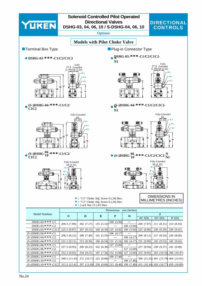
No.24
Solenoid Controlled Pilot OperatedDirectional Valves
DSHG-03, 04, 06, 10 / S-DSHG-04, 06, 10
Models with Pilot Choke Valve
Terminal Box Type
DSHG-03-∗∗∗-C1/C2/C1C2
(S-)DSHG-04-∗∗∗-C1/C2/C1C2
06 10(S-)DSHG- -∗∗∗-C1/C2/
C1C2
Plug-in Connector Type
DSHG-03-∗∗∗-C1/C2/C1C2-N N1
(S-)DSHG-04-∗∗∗-C1/C2/C1C2-N N1
06 10(S-)DSHG- -∗∗∗ N
N1-C1/C2/C1C2-
"C1" Choke Adj. Screw 6 (.24) Hex."C2" Choke Adj. Screw 6 (.24) Hex.Lock Nut 12 (.47) Hex.
DIMENSIONS IN MILLIMETRES (INCHES)

DIRECTIONAL CONTROLS
E
Options
Model Numbers
(S-)DSHG-06-∗∗∗-R2
C D E
376 (14.80) 558 (21.97)
111 (4.37) 164.5 (6.48)
40 (1.57) 65 (2.56)
Model Numbers
(S-)DSHG-06-3H
∗
C
306.5 (12.07) 456 (17.95)
D
102 (4.02) 149.5 (5.89)
Model Numbers C
323 (12.72) 479 (18.86)
D
84 (3.31) 125 (4.92)
(S-)DSHG-06-∗∗∗-P2
SOL a SOL b
SOL a SOL b
SOL a SOL b
A P B
SOL a SOL bA P B
SOL a SOL bA P B
Stroke Adj. Screw (Port "B" End) 17 (.67) Hex.
E
DFully Extended
CFully Extended
Fully Extended
93 (3.66)
Stroke Adj. Screw (Port "A" End) 17 (.67) Hex.
Lock Nut 24(.94) Hex.
Fully Extended289 (11.38)
33(1
.30)
Stroke Adj. Screw (Port "A" End) 13 (.51) Hex.
Stroke Adj. Screw (Port "B" End) 13 (.51) Hex.
Lock Nut 17(.67) Hex.
Fully Extended99 (3.90)Stroke Adj. Screw (Port "A" End)
13 (.51) Hex.Stroke Adj. Screw (Port "B" End)
13 (.51) Hex.
35(1
.38)
Lock Nut 17(.67) Hex.
Fully Extended252 (9.92)
D
C C
D
No.25
Solenoid Controlled Pilot OperatedDirectional Valves
DSHG-03, 04, 06, 10 / S-DSHG-04, 06, 10
Models with Stroke AdjustmentDSHG-03-∗∗∗-R∗
(S-)DSHG-04-∗∗∗-R∗
06 10 (S-)DSHG- -∗∗∗-R∗
Pressure Centred Models Models with Pilot Piston 06 10 (S-)DSHG- -3H∗
06 10 (S-)DSHG- -∗∗∗-P∗
DIMENSIONS IN MILLIMETRES (INCHES)

DIRECTIONAL CONTROLS
Installation Drawing
Sub-plate Model Numbers
DHGM-03Y-10 DHGM-03Y-1080
DHGM-03Y-1090
"C" Thd. "D" Thd.
Rc 3/4 3/4 BSP.F
3/4 NPT
"E" Thd.
13(.51)
15(.59)
Rc 1/4 1/4 BSP.F
1/4 NPT
M6
1/4-20 UNC
F mm (in.)
Sub-plate Model Numbers
DHGM-04-20 DHGM-04X-20
"C" Thd.
Rc 1/2 Rc 3/4
"E" Thd.
M10
3/8-16 UNC
1/2 BSP.F 3/4 BSP.F1/2 NPT 3/4 NPT
"D" Thd.
Rc 1/4
1/4 BSP.F
1/4 NPT
"F" Thd.
M6
1/4-20 UNC
DHGM-04-2080 DHGM-04X-2080DHGM-04-2090 DHGM-04X-2090
Valve Types
Spring Centred No-spring
Solenoid Controlled Pilot Operated Directional Valves
Pilot Operated Directional
Valves
Manually Operated Directional Valves
Spring Offset
Pilot Pressure Port "X" Port "Y"
Used only on external pilot type valves. To be plugged on internal pilot type valves.
Used
Not used (plug is not required)
Used as drain port only on external drain type valves. To be plugged on internal drain type valves.
Used as drain port
Used as pilot drain port
Used as pilot pressure port
120 (4.72)
90 (3.54)
15 (.59)
110
(4.3
3)
22(.8
7)
"D" Thd. Used only on external pilot type valves. To be plugged on internal pilot type valves.
"E" Thd. "F" Deep 4 Places
25 (.98)
19
(.75) 90
(3
.54)
46
(1.8
1)
10
(.39)
32.5
(1.2
8)
21.5
(.85)
6.4(
.25)
6.2(.24) Dia.6.2(.24) Dia.19
(.75)92
(3.62)
11
(.43)
12
(.47)
70
(2.7
6)
11(.43) Dia. 4 Places
18 (.71)
62 (2.44)54
(2.13)37.3(1.47)
27(1.06)
16.7(.66)
8(.31) 3.2 (.13)
"C" Thd. 4 Places
P
T
A
B
19
(.75)
25(.98)
42(1.65)
43(1.69)
50 (1.97)
10 (.39)
45 (1.77)
80 (3.15)
16(.6
3)
47
(1.8
5)76
(2
.99)
PTA B
XY
190 (7.48)
166 (6.54)
101.6 (4.00)
76.7 (3.02)
12(.47)
32.2(1.27)
50 (1.97)
34(1.34)
18.3(.72)
11(.43) Dia. Through 17.5(.69) Dia. Spotface 4 Places
3.6(.14) Dia. 5(.20) Deep 2 Places
14.2 (.56)
65.8 (2.59)
88.1 (3.47)
130 (5.12)
"E" Thd. 17(.67) Deep 4 Places
6(.24) Dia. 2 Places
17.5(.69) Dia. 4 Places
"F" Thd. 12(.47) Deep 2 Places
120
(4.7
2)
96
(3.7
8)
71.4
(2
.81)
12
(.47)
13.1
(.5
2)
69.8
(2
.75)
55.6
(2
.19)
14.2
(.5
6)1.
6(.0
6)
16
(.63) 10.1
(.4
0)57
.1
(2.2
5)
90
(3.5
4)
36 (1.42)
20 (.79)19
(.75)
P
T
A
B
X
Y
"D" Thd. 2 Places
125 (4.92)
90 (3.54)
46 (1.81)
65
(2.5
6)
29
(1.1
4)
58 (2.28)
102 (4.02)
137.5 (5.41)
76
(2.9
9)
21.5
(.85)
33(1
.30)
"C" Thd. 4 Places
"D" Thd. Used only on external drain type valves. To be plugged on internal drain type valves.
No.26
DHGM-03Y-10/1080/1090
DHGM- -20/2080/209004 04X
Sub-plate for Solenoid Controlled Pilot Operated
Directional Valves
DIMENSIONS IN MILLIMETRES (INCHES)

E
DIRECTIONAL CONTROLS
Installation Drawing
∗
F mm (in.)
Sub-plate Model Numbers "C" Thd. "E" Thd.
M12
1/2-13 UNC
Rc 3/4 Rc 1
3/4 NPT 1 NPT
"D" Thd.
Rc 1/4
1/4 NPT
24 (.94)
26 (1.02)
DHGM-06-50 DHGM-06X-50DHGM-06-5090 DHGM-06X-5090
Sub-plate Model Numbers "C" Thd.
3/4 BSP.F
1 BSP.F
DHGM-06-5080
DHGM-06X-5080
Dimensions mm (Inches)D E F H J K L N
151.2 (5.95)
155.2 (6.11)
137.7 (5.42)
148 (5.83)
102 (4.02)
106 (4.17)
54.4 (2.14)
50 (1.97)
30.6 (1.20)
25 (.98)
125.8 (4.95)
130 (5.12)
78.2 (3.08)
74 (2.91)
42.5 (1.67)
32 (1.26)
204 (8.03)
12 (.47)
"E" Thd. "F" Deep 6 Places
116
(4.5
7)
17.5
(.69)
53.2 (2.09)
29.4(1.16)
PT
A B
Y
X
V
7(.28) Dia. 8(.31) Deep 2 Places
11(.43) Dia. Through 17.5(.69) Dia. Spotface 4 Places
23(.91) Dia. "C" Thd. (From Rear) 4 Places
11(.43) Dia. "D" Thd. (From Rear) 4 Places
180 (7.09)
25 (.98)
130.2 (5.13)
112.7 (4.44)
94.5 (3.72)
77 (3.03)
5.6(.22)
19.1
(.75)
92.1
(3
.63)
74.6
(2
.94)
12
(.47)
46.1
(1
.81) 73
.1
(2.8
8) 96.9
(3
.81)
17.5 (.69)
29.5 (1.16)
100.8 (3.97)
126.2 (4.97)
12.5 (.49)
156 (6.14)
50 (1.97)
34(1.34)
35(1.38)
PT
A B
Y
X
V
W
204 (8.03)180
(7.09)12
(.47)25
(.98)130.2 (5.13)
M12 Thd. 24(.94) Deep 6 Places
11(.43) Dia. 4 Places
24.5(.96) Dia. 4 Places
12.5 (.49)
156 (6.14)
92.1
(3
.63)
110
(4.3
3)
134
(5.2
8)
8.9
(.35)
12
(.47)
11.9
(.4
7) 116
(4.5
7)
50 (1.97)
35 (1.38)
P T
AB
YW
D
E
F
H
J
N
L
K
73.1
(2
.88)
17.5
(.6
9)
19.1
(.7
5)
74.6
(2
.94)
46.1
(1
.81)
1/4 BSP.F Thd. 4 Places
"C" Thd. 4 Places
X
V
DHGM- -50/509006 06X
No.27
DHGM- -508006 06X
For other dimensions, refer to "DHGM-06∗-50/5090" above.
Sub-plate for Solenoid Controlled Pilot Operated
Directional Valves
For Uses of Port "X", "Y", "V", "W", refer to DHGM-10∗ on the following page.
DIMENSIONS IN MILLIMETRES (INCHES)
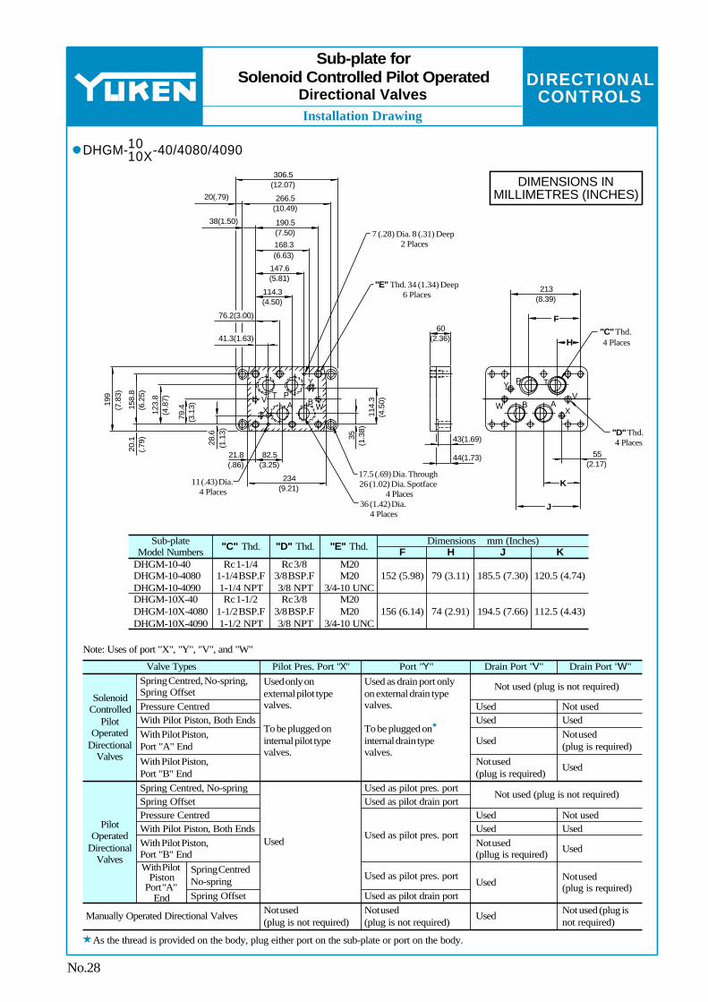
DIRECTIONAL CONTROLS
Installation Drawing
Sub-plate Model Numbers "C" Thd. "D" Thd. "E" Thd. F H J K
Dimensions mm (Inches)
DHGM-10-40 DHGM-10-4080 DHGM-10-4090
Rc 1-1/4 1-1/4 BSP.F 1-1/4 NPT
Rc 3/8 3/8 BSP.F 3/8 NPT
M20 M20
3/4-10 UNC152 (5.98) 79 (3.11) 185.5 (7.30) 120.5 (4.74)
DHGM-10X-40 DHGM-10X-4080 DHGM-10X-4090
Rc 1-1/2 1-1/2 BSP.F 1-1/2 NPT
Rc 3/8 3/8 BSP.F 3/8 NPT
M20 M20
3/4-10 UNC156 (6.14) 74 (2.91) 194.5 (7.66) 112.5 (4.43)
Spring Centred, No-spring, Spring OffsetPressure CentredWith Pilot Piston, Both Ends With Pilot Piston, Port "A" EndWith Pilot Piston, Port "B" End
Solenoid Controlled
Pilot Operated
Directional Valves
Used only on external pilot type valves. To be plugged on internal pilot type valves.
Used as drain port only on external drain type valves. To be plugged on internal drain type valves.
Not used (plug is not required)
Used Not usedUsed Used
UsedNot used (plug is required)
Not used (plug is required)
Used
Spring Centred, No-springSpring OffsetPressure CentredWith Pilot Piston, Both EndsWith Pilot Piston, Port "B" EndWith Pilot
Piston Port "A"
End
Spring Centred No-springSpring Offset
Manually Operated Directional Valves
Pilot Operated
Directional Valves
Used
Used as pilot pres. portUsed as pilot drain port
Used as pilot pres. port
Used as pilot pres. port
Used as pilot drain portNot used (plug is not required)
Not used (plug is not required)
Not used (plug is not required)
UsedUsedNot used (pllug is required)
Not usedUsed
Used
Not used (plug is required)
Not used (plug is not required)
Used
Used
Valve Types Pilot Pres. Port "X" Port "Y" Drain Port "V" Drain Port "W"
Note: Uses of port "X", "Y", "V", and "W"
F
H
K
J
W
Y P T
VAB
X
Y
BAPTV
X W
41.3(1.63)
76.2(3.00)
114.3 (4.50)
147.6 (5.81)
168.3 (6.63)
190.5 (7.50)
266.5 (10.49)
38(1.50)
20(.79)
306.5 (12.07)
28.6
(1
.13)
79.4
(3
.13)
123.
8 (4
.87)
158.
8 (6
.25)
199
(7.8
3)
20.1
(.7
9)
82.5 (3.25)
21.8 (.86)
234 (9.21)
35
(1.3
8)11
4.3
(4.5
0)
7 (.28) Dia. 8 (.31) Deep 2 Places
"E" Thd. 34 (1.34) Deep 6 Places
11 (.43) Dia. 4 Places
17.5 (.69) Dia. Through 26 (1.02) Dia. Spotface
4 Places36 (1.42) Dia.
4 Places
60 (2.36)
43(1.69)
44(1.73) 55 (2.17)
213 (8.39)
"C" Thd. 4 Places
"D" Thd. 4 Places
No.28
Sub-plate forSolenoid Controlled Pilot Operated
Directional Valves
10 10XDHGM- -40/4080/4090
As the thread is provided on the body, plug either port on the sub-plate or port on the body.
DIMENSIONS IN MILLIMETRES (INCHES)
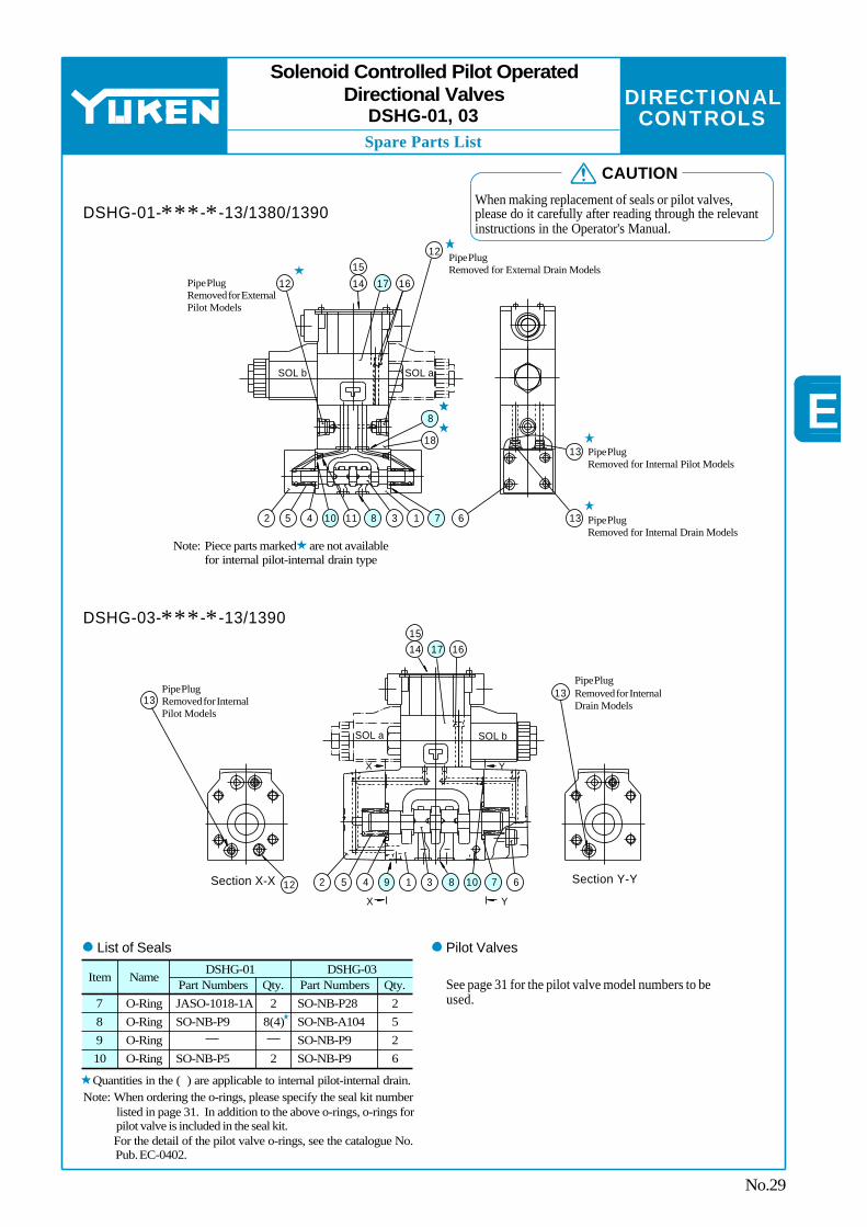
E
DIRECTIONAL CONTROLS
Spare Parts List
Item NamePart Numbers Qty.
DSHG-01Part Numbers Qty.
DSHG-03
78910
O-RingO-RingO-RingO-Ring
JASO-1018-1ASO-NB-P9
SO-NB-P5
28(4)
2
SO-NB-P28SO-NB-A104
SO-NB-P9
25
6SO-NB-P9 2
SOL b SOL a
12
161714
15
12
2 5 4 10 11 8 3 1 7 6 13
1318
8
Pipe Plug Removed for External Drain Models
Pipe Plug Removed for Internal Pilot Models
Pipe Plug Removed for Internal Drain Models
Pipe Plug Removed for External Pilot Models
SOL a SOL b
X Y
X Y
14 17 1615
1313
2 5 4 9 1 3 8 10 7 612
Pipe Plug Removed for Internal Pilot Models
Pipe Plug Removed for Internal Drain Models
No.29
Solenoid Controlled Pilot OperatedDirectional Valves
DSHG-01, 03
DSHG-01-∗∗∗-∗-13/1380/1390
Note: Piece parts marked are not available for internal pilot-internal drain type
DSHG-03-∗∗∗-∗-13/1390
Section Y-YSection X-X
List of Seals Pilot Valves
See page 31 for the pilot valve model numbers to be used.
Quantities in the ( ) are applicable to internal pilot-internal drain.Note: When ordering the o-rings, please specify the seal kit number
listed in page 31. In addition to the above o-rings, o-rings for pilot valve is included in the seal kit. For the detail of the pilot valve o-rings, see the catalogue No. Pub. EC-0402.
CAUTION
When making replacement of seals or pilot valves, please do it carefully after reading through the relevant instructions in the Operator's Manual.

DIRECTIONAL CONTROLS
Spare Parts List
Item Name(S-)DSHG-04SO-NB-P9SO-NB-P22SO-NB-P34SO-NB-P9
(S-)DSHG-06SO-NB-P14SO-NB-P30SO-NB-P40SO-NB-P10
(S-)DSHG-10SO-NB-P20SO-NB-P42SO-NB-P65SO-NB-P14
Qty.Part Numbers
2422
O-Ring
891018
14
1516 17
SOL a SOL b
X Y
X Y
18 10 5 4 1 3 9 13 8 2 7
12
11
11
Pipe Plug Removed for Internal Drain Models
Pipe Plug Removed for Internal Pilot Models
SOL a SOL b
X
Y
X
Y
16 14 17
15
21 21
18 2 10 5 3 1 9 13 8 4 7
11
11
12
12
Pipe Plug Removed for Internal Pilot Models
Pipe Plug Removed for Internal Drain Models
11 Pipe Plug Removed for External Drain Models
21
No.30
Solenoid Controlled Pilot OperatedDirectional Valves
DSHG-04,06,10 / S-DSHG-04,06,10
(S-)DSHG-04-∗∗∗-∗-51/5190
Section Y-Y Section X-X
(S-)DSHG-06-∗∗∗-∗-52/5290 (S-)DSHG-10-∗∗∗-∗-42/4290
Section Y-Y
Section X-X
List of Seals Pilot ValvesSee page 31 for the pilot valve model numbers to be used.
Note: When ordering the o-rings, please specify the seal kit number listed in page 31. In addition to the above o-rings, o-rings for pilot valve is included in the seal kit. For the detail of the pilot valve o-rings, see the catalogue No. Pub. EC-0402.
Note: Item orifice marked is applicable to pressure centred models (3H∗) with pilot pressure more than 10 MPa (1450 PSI).
CAUTION
When making replacement of seals or pilot valves, please do it carefully after reading through the relevant instructions in the Operator's Manual.


![Inducing Patent Infringement - Law Review...2005] Inducing Patent Infringement 229 understanding, inducing infringement is a natural outgrowth of the common law principle of respondeat](https://img.pdfslide.net/doc/110x75/5f9608d795a783197246401f/inducing-patent-infringement-law-review-2005-inducing-patent-infringement.jpg)