Embed Size (px)
Citation preview

Solution for Solar Power Generation
NR Electric Corporation
Integrated reliable and effective solution to PV power Generation

1
2
5
8
9
12
14
16
18
19
Solar Power Generation
PV Grid-Tie Inverter
Reactive Power Compensation
PV Power Prediction
PV Smart Step-Up Substation
Integrated Automation System
Centralized Control Center
Phasor Measurement Unit (PMU)
Power Stability Control System
VSC-HVDC Transmission

1 www.nrelect.com
Solar Power Generation
With continuous development of human society and gradually exhausted fossil fuel, the international community has committed to finding a new energy solution over years. The solar energy is a natural green energy, featuring safety, cleanness and inexhaustibility. The solar energy is inexhaustible and the solar energy received by the Earth in one hour can meet the demand of the human society for one year. The great Nature is showing us the huge potential of sunshine.
NR, the independent innovator in photovotaic(PV) grid interconnection technology and the leader in power system protection & control, can offer the integrated solution for inverters, substation monitoring and power prediction, PV power stations centralized monitoring and control, with the help of its rich experience over years in grid safety and stability control. NR’s products and services, which feature best performance, lowest cost and most safety and most reliability, will fully protect your PV power station and make your PV system higher effectiveness.

2 www.nrelect.com
PV Grid-Tie Inverter
PV grid-connection system refers to the system that converts solar power to electric power and transmits to the grid. It consists of solar array module, PV convergent cubicle, PV grid-connection inverter, and grid-connection system. The grid-connection inverter is the key equipment of PV grid-tie system.
System structure
PCS-9563 series PV grid-connection system consists of advanced IGBT controlled inverter, protection & control equipments and I/O switchgear etc. The system power capacity portion is designed in modularized structure featuring easy extension, convenient installation and maintenance, optimal layout, and less land occupation. The system control portion is based on the professional control & protection platform featuring abundant hardware resources, complete software functions, and flexible configuration of control/operation parameters, to maximally meet the extension demand of on system flexibility and extensibility.
The PCS-9563 series PV grid-tie inverter system structure is as follows:
MW power generating unit is designed with two PCS-9563 PV inverters connecting to the 10 kV/35 kV system via 3-winding step-up transformer. The structure is shown below:

3 www.nrelect.com
PV Grid-Tie Inverter
System function
• Operating modes
The PCS-9563 has three working modes—Standby, Run and Stop, two self-check statuses—Normal and Fault, several running control modes—PQ control, Voltage Frequency control and Low voltage ride through (LVRT) etc, and several auto control logics—Auto run”, Auto stop, Fault emergency stop etc.
• Auto start/stop
The PCS-9563 PV grid-connection inverter is designed with auto grid connection and manual control is not required. The inverter automatically detects the DC/AC system data in standby mode and automatically shifts to ‘Run’ mode for grid connection when the running conditions are fulfilled. It tracks the PV array maximum peak power (MPPT) in real-time and maintains the maximum power output during running.
• Auto fault processing
During grid-connected operation, the inverter detects the self-operation condition and the status of PV array and AC grid in real-time. Once any fault or abnormal condition is detected in the PV power generating system, the inverter will stop running, send out alarm signals and enter fault emergency stop mode. The detailed fault information will be displayed on the LCD of control devices. The inverter will continuously detect the system status in fault mode and automatically restore running after the system fault is cleared for 5 minutes.
• Running functions
- SCADAThe SCADA function acquires and processes the real-time system operating data of the PV system, including
battery DC voltage, inverter running data etc, send out alarm and update the automation system database.
- Soft grid-connection controlThe control system can accurately control the inverter output voltage in real-time based on the detected grid voltage and eliminate dynamic/static error to realize impulse-free connection.
- Maximum Peak Power Tracking (MPPT) controlThe system can search the maximum peak power based on the collected battery physical data and control the real-time tracking of inverter to achieve the maximum power utilization.
- Dynamic Var controlIn case of voltage drop in the grid, the control system can provide automatic reactive power compensation to maintain the grid voltage based on the voltage dip and duration.
- Island detectionThe system can rapidly detect the appearance of island condition and handle it according to the preset configuration.
- Low voltage ride through (LVRT) operationThe PCS-9563 inverter can maintain grid-connected operation and realize LVRT in case of low voltage fault in the grid.
- Power quality (PQ) controlThe system is designed with grid-connected power optimization to ensure power quality.

4 www.nrelect.com
PV Grid-Tie Inverter
Features
• Producttestingandcertification
The PCS-9563 inverter has passed the LVRT field test by SGEPRI and Qinghai Electric Power Research Institute in Qinghai PV Power Station.
• High reliable and long-life system design
The primary/secondary components of the inverter have good quality and long operation life. The component selection, power design, and heat dissipation design are all based on high altitude and extreme adverse conditions with margin to ensure the reliable system operation and working life. The inverter adopts modular design to ease installation and maintenance, including IGBT module and other major equipments. The large capacity IGBT modules are used to reduce parallel connections and increase equipment reliability. The optical triggering method has strong anti-interference capability and the patented heat dissipation scheme is employed to achieve high reliability and efficiency.
• High-performance and reliable control devices
The control & protect ion devices features wel l performance, high reliability and mature hardware/software technologies. The core controller is equipped with the most advanced floating controller which has advantages of high main frequency, large memory capacity, and high computation and control accuracy. The control system fully supports IEC61850 and IEC60870-5-103 etc. The equipment uses integrated front panels and enclosed rack that it can protect against dust and
ensure the safe and reliable operation of control system during the service life of PV power station.
• High power quality
The grid-connection power quality controlled by PCS-9563 is far higher than that defined in the relevant codes and standards. In the certified test by CGC-SOLAR, both the total harmonic distortion of voltage (Uthd) and current (Ithd) are smaller than 2%, the voltage on connected network is even smaller than 1% at rated power.
• Complete and reliable protection functions
PCS-9563 system has inherent protection for IGBT modules by detecting abnormal dv/dt and di/dt in IGBT and blocking the triggering pulse instantly. As a result, it can ensure safe and reliable operation or rapid and safe shutdown even in severe environment.
Inverter phase A transient input current
System transient voltage
Figure. PV Inverter Output Waveform
5 www.nrelect.com
Reactive Power Compensation
The PV power station Var compensation solution is implemented by PCS-9580 static Var compensator (SVC) and PCS-9581 static synchronous compensator (STATCOM). SVC/STATCOM serves as a Var source and it can supply reactive power to the grid or absorb the excessive reactive power in the grid. SVC/STATCOM
can benefit the PV power station as described below:
• To perform dynamic Var compensation and improve power factor;
• To curb harmonic;
• To suppress voltage fluctuation and flickering;
• To offer reactive power locally, stable the voltage and reduce losses of transmission lines;
• To make up for system imbalance.
Static Var Compensation
PCS-9580 static Var compensator (SVC) is provided with the TCR+FC structure where it is connected to the LV busbar of PV power station, the current flowing through the air-core reactor can be adjusted by the triggering angle of the SC valve bank and the reactive power absorbed by the reactor can be continuously adjusted.
• Thyristor valve bankThe thyristor valve bank is the core primary equipment for SVC control. The valve consists of a certain number of thyristors and accessories in shunt and series connected. The valve bank is equipped with efficient and compact water cooling method and triggered by TCU (Thyristor Control Unit) photo-electric triggering method.
• Filter bankThe filter bank supplies capacitive Var to the system and eliminates the harmonic from the grid and generated by TCR. It consists of capacitor, reactor and resistor.
• Valve bank cooling systemThe thyristor valve bank is cooled by mature and reliable enclosed system with pure water (deionized water).
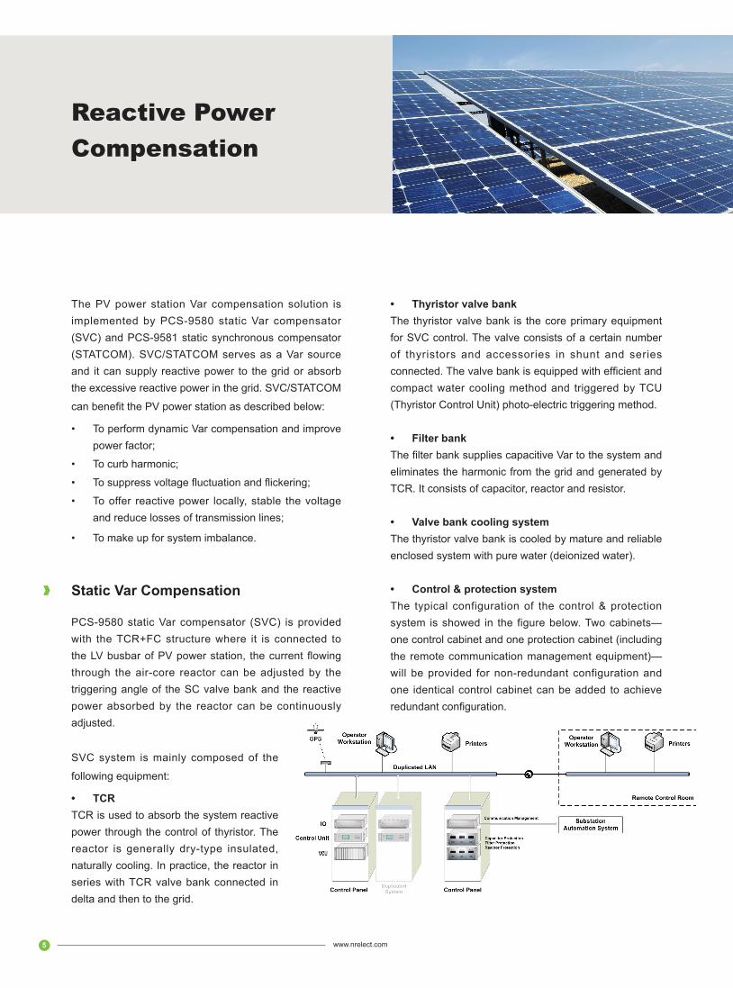
• Control & protection systemThe typical configuration of the control & protection system is showed in the figure below. Two cabinets—one control cabinet and one protection cabinet (including the remote communication management equipment)—will be provided for non-redundant configuration and one identical control cabinet can be added to achieve redundant configuration.
SVC system is mainly composed of the
following equipment:
• TCRTCR is used to absorb the system reactive power through the control of thyristor. The reactor is generally dry-type insulated, naturally cooling. In practice, the reactor in series with TCR valve bank connected in delta and then to the grid.

6 www.nrelect.com
Reactive Power Compensation
- Features• Professional system design, and customized
products to meet various demands;
• Compact and tower type thyristor valve bank, minimized land consumption;
• State-of-the-art photoelectric triggering method, non-BOD thyristor over-voltage protection;
• Patented water-cooling system, low thermal obstruction, low water resistance, small in size, high efficiency;
• Enclosed pure water-cooling system, parallel water routings, reliable operation;
• Rapid system response (measured open ring response time: 7 ms)
• High control accuracy (0.01°), wide control range (102° -165°);
• Distributed control protection system of high performance, minimum disconnection time: 25us;
• Friendly HMI, easy operation and maintenance; and
• Modular system design, compatible with future upgrade, long-term guarantee of spare parts.
Static Synchronous Compensator
The main circuit of PCS-9581 Static Synchronous Compensator(STATCOM) is based on VSC—voltage source compensator where the reactive power can be regulated from inductive to capacitive continuously by adjusting VSC output voltage amplitude and phase angle.
SVG system is mainly composed of the following equipments:
• Damping reactorThe damping reactor is used to connect VSC to system 10kV busbar or step-down transformer of higher voltage level .
• IGBT valve bankIGBT valve bank, the core primary equipment of STATCOM, is composed of a certain number of IGBT and accessories.
• Valve bank cooling systemThe IGBT valve bank adopts air cooling or cooled by enclosed system with pure water (deionized water). The air-cooling method is applied to small-size applications and the efficient and compact water-cooling method to big-size applications.
• Control & protection systemThe same as SVC.

7 www.nrelect.com
Reactive Power Compensation
- Features• Professional system design, and customized
products to meet various demands;
• Patented compact and tower type IGBT valve bank, minimized land consumption;
• State-of-the-art photoelectric triggering method, over-voltage triggering with short-circuit protection;
• Rapid system response (measured open ring response time: 3~4 ms);
• Negative-sequence and act ive f i l ter control functions;
• Friendly HMI, easy operation and maintenance; and
• Modular system design, compatible with future upgrade, long-term guarantee of spare parts.
System function
• Control modeSVC is designed with voltage control, Var control, power factor control, Volt/Var integrated control, negative-sequence control, TCR DC current control, and manual susceptance control.
STATCOM is designed with voltage control, Var control, power factor control, Volt/Var integrated control, load Var rapid compensation control, harmonic eliminating control, constant Var control (locally or via dispatching center), voltage control on DC side etc.
The comprehensive control modes can realize various control goals.
• Sequential control and interlocking functionThe sequential control refers to sequential operation of SVC/SVG startup/shutdown and switching of various control modes and running modes. Software interlocking is provided for various operations and the system will not respond to wrong operation sequence. In addition, the system can automatically switching on and off the capacitor/filter bank as required by control goals.
• Complete self-check and protection functionsThe self-check function covers the control system, I/O unit, valve triggering system, bus and valve bank main body etc. The self-check period can ensure it can detect the internal fault in 1ms and block corresponding triggering pulse or trip the breaker.
RCS series protection products for branches have run in thousands of substations in China for years and they can be installed into the switchgear as required.
• On-line harmonic detectionThe control system is integrated with on-line harmonic detection so that additional data acquisition unit is not required. It can share the data via communication bus. And an independent harmonic analysis software module is added to perform all data analysis and computation. The operators can view the harmonic at each measuring point on the harmonic analysis interface in their workstation.
• Transient fault recorderThe system can record pre-fault and post-fault signal in COMTRADE format and save in the directory shared by operators for fault analysis.

8 www.nrelect.com
PV Power Prediction
The PV power prediction system is used to predict the output power of PV power station in a upcoming period. The system computes reliable prediction based on high accurate numerical weather prediction (NWP), with acquired site monitoring data, environment data and history statistical data through the process of physical model and artificial neural network (ANN) model.
The PV prediction system is recommended to install separately from PV power station CSCS system.
• It will communicate with the PV power station CSCS via a firewall to acquire measured data;
• It will communicate with the weather processor server on the Internet via reverse isolat ion equipment to acquire the NWP data;
• It will communicate with the prediction master station via the dispatching data network to send out the short/extra-short-term PV power prediction.
Systemconfiguration
NR’s PCS9700 PV power prediction system consists of two power prediction servers (main/standby), one weather data processor server, one WEB-based engineer workstation, one reverse isolation equipment, and one fire wall.
The ground radiation intensity, temperature, wind speed etc should be acquired for PV power prediction so that
the environmental monitor shall be provided, which is generally integrated by the PV power prediction supplier.
Features
• Advanced and mature software platform: The PV power prediction system is based on NR’s SOPHIC platform. The platform features such virtues as advanced architecture, mature and stable performance and has been applied to a series of national key projects.
• Advanced prediction algorithm: The physical model and ANN are used for power prediction to ensure prediction accuracy.

9 www.nrelect.com
PV Smart Step-Up Substation
PV Smart Step-Up Substation
The digital step-up substation consists of intelligent primary equipment and network-based secondary equipment in layers based on IEC61850 where information sharing and interoperability can be realized among the intelligent equipment. Compared with traditional step-up substations, the digital one has the following changes: The equipment and network interfaces on the substation/bay control layer have changed only in the interface and communication models but great changes have taken place on the process layer—the traditional CT/VT, cable connection among primary equipment and between the primary equipment and the secondary equipment have been replaced by ECT/EVT, intelligent primary equipment, merging unit, FC etc.
The process level within the substation is provided with optical double star networks, which are independent from the step-up substation CSCS network. The advanced network sharing technique is adopted for process level GOOSE and digital sampling SMV issuing message. It simplifies network equipment while system reliability and security are assured.
- Features• Based on IEC61850 that is future-oriented, smart
grid-oriented and intelligent substation-oriented so that it is interoperable, easy to learn and high maintainability;
• The scheme is provided with IEC61850 digital substation network system in three layers and two networks where the supervisory control
layer network and the process layer network are independent from each other to ensure security and stable of substation network system;
• ECT/EVT and intelligent terminals are applied with digital process layer technology to perform complex and advanced protection functions, this simplifies the secondary wiring and reduce system design, construction and maintenance cost.
• It is accumulated experiences based on the successful application of products and technologies in many digital substations.
Measurement & Control for Step-Up Transformer
PCS-9721D step-up measurement & control equipment is used for status measurement, breaker control, non-electric quantity protection and remote data transmission of the box-type step up transformers in wind farms and PV power stations.
- System structurePCS-9721D step-up transformer measurement & control equipment is provided with high performance processor based on HTM patented technology. I t features standard hardware interfaces and modular software functions, long life, compact structure, novel design, strong performance, flexible configuration and strong compatibility. The equipment is based on the platform so that it can meet various demands by means of flexible interface/card configuration. The logic diagram of the step-up transformer measurement & control system is shown below:

10 www.nrelect.com
PV Smart Step-Up Substation
- System Functions• Tele-measurement of AC quantityIt can perform measurement and computation of such AC quantities as phase voltage, line voltage, phase current, active/reactive power, apparent power, power factor, frequency etc.
• Tele-measurement of temperature and DC quantity
It can measure the transformer oil/winding temperature and the ambient temperature by means of Pt100.
Some non-electric quantities, such as temperature, pressure etc, can be converted to DC analog quantities by the transducer. Various types of DC voltage/current can be accepted at local terminal, including 4 mA-20 mA, 0~10 mA, 0-5V, 0-10V, 0-250V, which can be flexibly configured as required.
• Tele-signalingPosition status and other status data can be acquired via binary inputs, such as HV switch open/close position, LV switch open/close position, pressure relief signal, buchhloz gas trip, buchhloz gas alarm, high temperature trip, high temperature alarm, low oil level alarm, abnormal SF6 pressure and other customized input.
• ControlIt can perform remote switching of step-up transformer.
• Non-electric quantity protectionProtection trip: buchhloz gas trip, transformer high temperature trip.
Transformer abnormal alarm: To transmit remotely the transformer high temperature alarm, transformer low oil level alarm, buchhloz gas alarm, SF6 abnormal pressure alarm via binary input.
• Communication functionsMultiple communication media available: FC Ethernet, Electrical Ethernet, RS-2M/RS-485 series ports.
It can support several protocols and extend the protocol modules as required, it can support IEC608-70-5-101:2002, IEC 60870-5-104, IEC60870-5-103, Network 103 protocol, and Modbus protocol as basic protocol configuration.

11 www.nrelect.com
- Features• Reliable and stable operationPCS-9721D, applicable to extreme environment, is designed with good EMC, low power consumption, wide working temperature range, vibration-proof and humidity-proof as well as good reliability and stability.
• Plentiful and applicable functionsPCS-9721D is designed with complete functions and can be flexibly configured as required.
It is designed with measurement, control and protection functions to perform measurement, control and fault detection on step-up transformers.
It is designed with FC Ethernet so that the on-line supervision and measurement terminals can support Ethernet (100M) and the distribution network terminal can be directly connected with optical fiber to form Ethernet, featuring less optical transceivers, simple construction and reliable communication.
It is designed with multiple communication ports, including RS-232, RS-485, electrical Ethernet, FC Ethernet, FC ring Ethernet, GPRS etc.
• Open and extensible systemThe terminal software/hardware platform is designed with open interfaces and extension margin for future extension and technical upgrade.
The device plug-ins are designed with consistent interfaces to offer strong compatibility and easy plug-in module of new functions.
PV Smart Step-Up Substation
The functional software is designed in component so that they are independent from each other, offering good software interface for future functional upgrade and extension.
The protocols are developed in modular mode. In addition to the basic configuration, new protocols can be extended as required. The basic configuration can support standard protocols, including IEC101, IEC104, IEC103, Network 103, MODBUS, DNP etc.
• Easy and safe maintenanceIt is designed with self-diagnosis and self-recovery functions.
It is provided with large-size memory so that a large amount of data, statistical data can be saved for inquiry.The data are saved even in case of long-term power loss so as to ensure the security of terminal important data.The debugging and maintenance software are provided with consistent operating interfaces, strong function,
easy installation and operation.

12 www.nrelect.com
Integrated Automation System
The PV power station solution is based on PCS-9700 CSCS and takes into account the characteristics of PV power stations. The system can perform real-time monitoring and control on the PV solar array, DC current convergent cubicle, DC distribution cabinet, grid-tie inverter, step-up substation, step-up substation, and environmental monitoring system. It is designed with rich user interfaces; strong analysis and processing functions
as well as complete monitoring alarm mechanism.
System Structure
The system consists of three-layer control equipment and two-layer networks. The former includes the equipment on the local layer, the control layer and the substation control layer and the latter includes the network of the power station/substation layer and the control layer. The equipment on the substation control layer and the control
layer are mounted in the computer room and the main control room in the CSCS main control building and the equipment on the local layer are distributed mounted in the inverter room of the power station.
The network on the control layer is designed with optical 100Mbps industrial Ethernet (single). The network on the generator unit control layer is composed of optical Ethernet. The network on the substation control layer is composed of optical 100Mbps industrial Ethernet, in double host, double network, double
channel redundant design.
System Functions
- Data Acquisition and Processing
• Data acquisition

13 www.nrelect.com
The local equipment in a PV power station consists of convergent cubicle, DC cabinet, inverter, box-type step up transformer with measurement and control unit. The CSCS will acquire the real-time data of the local equipment via the intelligent serial communication devices in data acquisition cabinet of the inverter room. The intelligent interfacing devices will transmit the real-time data marked with quality description to the host on the control layer via the control layer Ethernet.
• Data processing
Over limit check: Check the measured analogue signals and send out alarm when any of them is over limit, record the number of override position, occurrence time and the over limit value into the database;
In case of position change of DI/DO: record the operation sequence, event occurrence time, name of the event, nature of the event and issue alarm and report as specified.
- Control & Operation• Perform Watt/Var control of generator unit;
• In/Out generator unit;
• On/Off CB/DS (disconnector);
• Control the local equipment via communication;
• Automatic generation control; and
• Automatic voltage control.
- Operation Monitoring and Event Alarm• Status change monitoring: Monitor the real-time
parameters and status of the substation systems and display on the monitor; it will automatically switch to fault display in case incident/fault is detected; and it
will also automatically recall the incident/fault display even the monitor is in dark screen;
• Fault display/record: make records in chronological sequence for all detected incidents and send out incident sound and audio alarm;
• The manual operation command is in both the scope of SOE and operation records;
• Alarm handling and make SOE records;
• PDR and relevant quantity records: The system will record 20 samples pre-fault and post fault within the sampling period of 1s.
- Tele-Control FunctionPower station and step-up substation will communicate with dispatching center via the same communication device to transmit real time data. The communication device can also perform data processing and protocol conversion to meet the requirement of automatic dispatching. In addition, it is provided with serial output and network output capacity to meet the communication requirement with the master station of each dispatching center via dedicated channel and dispatching data network channel.
Features
• Unif ied data platform, seamless connection of supervisory control systems of the step-up substation and the power station;
• Complete series of protection, measurement and control with stable, reliable and advanced products;
• PV power station AGC application can realize optimal power distribution, improving the economical and running efficiency.
Integrated Automation System

14 www.nrelect.com
Centralized Control Center
More and more solar power stations have been built and put into service. Accordingly, the owner wants to centralize monitoring and control the operation of PV power stations, acquire their data and perform storage, display, analysis and statistics so that real time conditions of equipment running, power generation and running level of the PV station are understood and taken as reference for future construction, design, equipment selection and economical operation of PV power stations.
System Functions
Centralized Control Center (CCC) can centralize the monitoring and control of PV power station equipment and process the data to provide complete and
convenient data and services to the operators, maintenance personnel and management.
The system provides various user interfaces, display modes and data etc. for operators, management and maintenance personnel respectively. It can provide equipment status, alarm and real-time data etc. for operators; various monitoring data statistics, variation trend, status information for management; alarm, variation trend, fault disturbance record data etc. for maintenance personnel. In addition, it can monitor the equipment in the PV power station as well as the surroundings via video information.
- Data Acquisition and ProcessingCCC will acquire the data of step-up substation, inverter and current convergent cubicle in the PV power station; wind,

15 www.nrelect.com
light and other environment conditions; on-line monitoring data such as power quality, primary equipment status etc.There are two types of data—analog one and digital one. The analog data consist of measured electrical analog data such as voltage, current and power etc and measured non-electric analog data such as inverter, wind, light, environment etc. The digital data consist of interrupting digital data such as fault event signal, CB and main protection operation signals etc. and non-interrupting digital data such as various fault signals, CB and DS position signals, inverter status signals etc.
- Running MonitoringIt can real-time monitor the operation condition of PV power station and display the major running parameters and equipment status of the PV array, current convergent cubicle, inverter and step-up substation via mimic diagram, trend diagram, bar chart and parameter table in categories. The arrangement of graphics can be customized as required.
The system is designed with web-based monitoring interfaces to display various graphic interfaces of dynamic and static running information from real-time acquisition, processed, system estimated and manually set.
- Control Operation• Remotely open/close the CB/DS;
• Remotely start/stop the inverter;
• Power control of inverter power generation.
Above control functions can be performed in the CCC, PV power station and local control equipment. The
priority of control authority is as follows: Local control is superior to PV power station and PV power station control is superior to CCC.
- AlarmThere are two types of alarms—fault alarm and warning alarm. The fault alarm consists of CB trip and protection device operation signals that are not caused by manual operation; the warning alarm is generally composed of equipment position change, status abnormal information, analog parameter over-limit reset, computer control system component and bay unit abnormal status etc.
It can send out sound/light/audio alarm when fault occurred with the content displayed in the front for easy checking.
- ReportThe report format can be set and the parameters showed on the report can be selected. The system can display and print out reports of daily/monthly/yearly comprising all measured parameters of current convergent cubicle and inverter bank in each PV power station.
Features
• Object-oriented, distributed real-time database management;
• Friendly HMI;
• Practical reports;
• Security and applicable WEB system;
• Highly reliable front-end system;
• Panoramic fault record.
Centralized Control Center

16 www.nrelect.com
To improve the dynamic monitoring and analysis capacity of the power system dispatching center on power system, a synchronous phasor measurement equipment shall be installed in the key PV power station to establish the real-time dynamic monitoring system for the power system after the PV power station is connected to the grid. The system will become one of the major data sources of dynamic real-time data platform in the power system dispatching center. In addition, it will be gradually combined with EMS and the security automatic control system to strengthen the supervisory control over the power system dynamic security and stability, improve the capacity of the dispatching center on understanding system running conditions, and facilitate the study on dynamic process of large grids, offering reference for control strategy, design, running, and scheme planning of power system.
PCS-996 series synchronous phasor measurement unit (PMU) is developed to perform power system phasor measuremen and dynamic process record. PMU features synchronous phasor measurement based on standard clock signal, time keeping in case of standard clock signal losses, real-time communication between
Phasor Measurement Unit (PMU)
System function
PCS-996 series synchronous phasor measurement equipment consists of phasor acquisition unit (PCS-996A/B) and data centralized processing unit (PCS-996G).
PCS-996A synchronous phasor measurement unit acquires and records the electrical and digital data of busbar, circuit and main transformer of substations and power stat ions, performs computat ion and analysis of voltage/current amplitude, phase angle, linear combination power etc, and transmits real-time fundamental positive sequence voltage phasor primary value, fundamental positive sequence current phasor primary value, frequency difference, rate of change of frequency to the data concentrator and then to the master station.
PCS-996B synchronous phasor measurement unit is used for the synchronous phasor measurement of power generator units. In addition, it can acquire, compute and record 4-20mA signals such as generator internal potential, power angle, excitation voltage, current, speed, frequency regulation etc. and output 4-20mA signals. Besides, it can record digital data of PSS, AVR,
PMU and master station, and compliant with relevant communication protocols.
PCS-996 series synchronous phasor measurement unit can form WAMS (wide area measurement system) with GPS clock synchronization system, high-speed communication network equipment, sub-station and master station analysis system to realize dynamic process monitoring and analysis on large grid of a region of cross regions.

17 www.nrelect.com
Phasor Measurement Unit (PMU)
• The data concentrator is based on UAPC. It has the same reliability as PCS series protection devices. Comparing with other Industrial Personal Computer (IPC)-based solutions, it has higher reliability and more flexible configuration, can connect 8~16 PMU acquisition units and up to 4 master stations and has large-size memory over 128G.
• PMU real-time data transmission is performed by fiber channel from the acquisition unit to the data concentrator so that photo-electric converter is not required, completely isolated from dynamic/transient data, event message and other data communication, assuring PMU higher real-time performance.
• High resolution IRIG-B code is employed for GPS timing, optical and RS-485 interfaces are supported.
• It is compliant with “Technical Code on Real-Time Dynamic Detection System of Power System”, IEEE Standard C37.118-2005 “Power System Synchronous Phasor Code”, DL/T667-1999 (IEC60870-5-103) and IEC61850.
• It is provided with flexible communication modes—at least 4 independent Ethernet interfaces and 4 independent RS-485 interfaces. It is compliant with IEEE Standard C37.118-2005 “Power System Synchronous Phasor Code”, DL/T667-1999 (IEC60870-5-103) and IEC61850.
• It is provided with friendly HMI, 320X240 LCD, and Chinese/English display selected via setting.
• It is provided with whole front panel and enclosed casing where the different voltage levels are separated from each other. Compared with the traditional back plate construction, it has stronger anti-interference capacity and best EMC capacity.
operation of frequency regulation etc. Meanwhile, it can transmit realtime fundamental positive sequence voltage phasor primary value, fundamental positive sequence current phasor primary value, frequency difference, rate of change of frequency and generator internal potential to the data concentrator and then to the master station.PCS-996G data concentrator: PCS996G, associated with PCS996A/B, is based on UAPC platform. It can receive synchronously the real-time/dynamic/transient data and SOE as well as event response from PCS996A/B, and then transfer them to each WAMS master station as per IEEE 1344 and save the received real-time/dynamic data to CPU inherent large capacity memory.
Features
• PCS-996 is new generation of PMU that can fully support digital substations. It can support both ECT/EVT and conventional CT/VT and new substation communication protocol--IEC61850. In addition, the wiring terminals are compatible with RCS-900 series EHV line protection which is widely used in China.
• The hardware is based on PCS series protection platform UAPC. 32-bit high-performance CPU and DSP, internal high-speed bus, intelligent I/O, hardware/software are modular designed so that it features flexible configuration, universal application, easy extension and maintenance. I t can be centralized or distributed installed.
• The operation system adopts Linux open-source system so that it has such virtues as small core, high security and stability, strong network communication capacity. It is applicable to the industrial control field with high requirements on reliability and communications etc.

18 www.nrelect.com
Power Stability Control System
Solar power, a renewable clean energy, has drawn more and more attention in recent years. The PV power generation is towards large scaled constructed and grid-connection. The impact of PV power on the grid shall be taken into account when the PV power accounts for a certain percentage in the grid. The PV output has close relations to the sunshine. The intermittent output and single-peak curve results in complex load flow distribution and voltage characteristics as well as big effect on transient stability. When the system has severe faults, it may result in disastrous consequence. Therefore security and stability control system is necessary for a grid with large scaled PV power.
System Structure
The security and stability control system for power grid with PV power is recommended to install an equipment in each PV power station, primary PV substation and connect to a master control equipment in a key station connected to the grid.
• Each control equipment in PV power station can acquire the PV unit power from incoming circuits, transmit the data to primary PV substation and receive command for switching the incoming circuits.
• Each control equipment in primary PV substation will collect the data of each PV unit, transmit to the master control equipment, receive the command of switching PV units from the master control equipment and distribute the switching among the PV power stations .
• The master control equipment will receive the PV unit data upload from primary PV substations, and send out the command to the primary PV substations based on the stability control strategy to achieve grid control coordination.
Systemconfiguration
PCS-992 stability controller is designed in distributed architecture and composed of one central unit and several slave units. Slave units will perform sampling, computation and unit fault judgment and send out the results to the central unit. The central unit collects the judgments from bay units, receives the information and command from other stations, and realizes the stability control of PV power connection to the grid in accordance with the on-line or off-line computation stability control strategy.
PCS-992 Stability Controller

19 www.nrelect.com
VSC-HVDC is the state-of-the-art technology in power electronics in the world. It has strong technical advantages in power system stability, dynamic Var storage, power quality, non-linear loading, effect of impulse load on system, sensitive equipment power supply security etc. Due to its technical characteristics, VSC-HVDC is applicable to renewable energy grid-connection, distributed power stations grid-connection and is land power supply. I t has more obvious advantages in wind power grid-connection, offshore platform power supply and power supply of grids in metropolitan. It is undoubtedly useful in grid connection of PV power stations.
System principle
VSC-HVDC is a new DC transmission technique based on voltage source converter(VSC), controllable switch and pulse width modulation (PWM). It was first developed in 1990s. HVDC can perform transient Var/Watt separate de-coupling control and supply to load center, no communication is required between converters, and it is easy to establish multi-terminal DC system.
The VSC-HVDC system consists of two converters and DC cables. The converters at both ends is based on VSC technique and composed of IGBT and GTO etc. Since he converter is composed of switchable power electronic components, it has no requirement on the capacity of the receiving end.
The VSCs at both ends serve as rectifier and inverter. The converter transformer and reactor on AC side serve
as energy exchange and filter between VSC and AC system. HVDC is generally provided with underground/submarine cables, and thus it has little influence on environment.
Features
VSC-HVDC transmission is based on controllable switchable power electronic components and PWM technology. Compared with classic AC access modes, it has the following features:• VSC-HVDC can control Var/Watt rapidly and
independently, offering more flexile control;
• VSC-HVDC does not need the reactive power suppl ied from AC system and can serve as STATCOM to perform dynamic Var compensation and stabilize the busbar voltage. That is to say, if the VSC capacity is sufficient in case of fault, HVDC can offer both Watt and Var to the fault system, improving system phase angle stability and system voltage stability.
• VSC-HVDC technology can be used to form multiple-terminal DC systems, enhancing the flexibility and reliability of PV power station switched in.
• Since the current on the AC side of VSC-HVDC transmission is controllable, the system short circuit capacity will not be increased, thus it is unnecessary to change the protection settings after new HVDC is connected.
VSC-HVDC Transmission

Copyright © NR 2012.04 All rights reserved
NR Electric Co., Ltd.
Add: 69 Suyuan Avenue, Jiangning, Nanjing 211102, ChinaTel: +86-25-8717 8888 Fax: +86-25-8717 8999Website: www.nrelect.com (En)
www.nari-relays.comE-mail: [email protected]