Embed Size (px)
Citation preview
71
Powder Technology, 9 (1974) 71-39 @ Elsevier Sequoia S-A-, Lausanne - Prmted in The Netherlands
Some Aspects of the Characteristics of Vertical Screw Conveyors for Granular Material*
F.J C. RADEMACHER
Afdeling der Werktuigbouwkunde ucn de Technische Hogeschool Twente, Enschede (The Netherlands)
(Received July 18, 1973)
Summary
A theory has been developed, based on a physical model, to describe the behaviour of non-cohesive granular material inside a ver- tical screw conveyor. By use of this theory, relationships have been derived between di- mensionless numbers for capacity, power con- sumption and efficiency. These relationships, or characteristics, are compared with the re- sults of experiments carried out with two models of vertical screw conveyors, one of 50.8 mm and the other of 162.0 mm diam- eter_ The agreement between the calculated and the measured values of capacity and power consumption was within 5 and 9% respectively.
The investigation was extended to a screw with an inclined screw blade, because one might expect that this would result in a steep- er upward motion of the granules and thus would lead to an increased capacity_ It ap- pears, however, that this type of screw has no practical advantages over the normal one, and it is therefore not treated here.
Two other simpler theories were also devel- oped, one based on a simphfied physical model [27] and the other on the conveying of a single granule [28] _ It appears that the simpler theories do not agree with the experi- ment as well as the one developed in this dis- sertation does, the theory of the single gran- ule producing the greatest discrepancies_ With the latter theory, however, the capacity can be reasonably well approximated when the ‘degree of fullness’ S 60%.
The influence of the inlet section on the
* Essentials from ‘The vertical screw conveyor’ by the same author; Doctor’s Thesis, Twente University of Technology, 1972.
performance of the screw conveyor is dis- cussed. It was found that the capacity of the conveying section is in most cases limited by the inlet and not by the conveying section itself. As the maximum performance of the conveymg section can be calculated with the more developed theory, a method is thus available for judging the potential increase m capacity which could be obtained through improved inlet design.
INTRODUCTION
The object of this mvestigation is to obtain a theoretical prediction of the capacity, effi- ciency and required power of vertical screw conveyors. The main problem, which becomes evident from the study of such conveyors, is to know whether the conveying or inlet sec- tion limits the capacity_ The geometric design of the conveying section is more or less fixed by the nature of the screw conveyor itself. For most screws, for example, the pitch is approximately equal to the diameter, and the shaft diameter is 35% of the diameter. The design of the inlet section, however, offers many possibilities. One of the simplest inlet- section constructions, 2-e. the one where the screw protrudes free for a certain length from under the tube, is used frequently. In this case it is possible to insert the lower part of the conveyor in the granular material to be trans- ported; the latter can then flow in from all sides. In many cases it is not known if the capacity of the inlet section is balanced against that of the conveying section. If, under special circumstances, the flow of gran- ular material is restricted, e.g., if in a partic- ular construction only lateral flow by way of a tube is possible, it is often more difficult to
72
construct the inlet section in such a way that the capacity of the conveying section is fully utilized_
Therefore many different designs of the inlet section are commercially available_ It is generally not known which of these designs is the ‘optimum’, since the characteristics of the conveying section must previously be known. Therefore the characteristics of the conveying section will be defined and investigated first, and the main problems of the inlet section afterwards_
It will be shown that the behaviour of the conveying section can be described in terms of dimensionless numbers; the theoretical relationships are based on a physical model.
THE CONVEYING SECTION
1. Dimenszonless numbers The use of dimensionless numbers has the
practical advantage that fewer experiments need to be carried out to determine the char- acteristics of a given system. Moreover, the relations between the relevant quantities can be clearly represented in a relatively small number of graphs.
In practice, the bulk density and the de- sired capacity of the material to be conveyed are known. Thus the nett power consumption per axial unit length can easily be calculated. This quantity is independent of screw geome- try and is therefore a useful component of dimensionless numbers. Consequently the gross power consumption per axial unit length will also be used in the dimensional numbers.
The gross-power consumption will depend on:
(1) the inner tube radius, r, (2) the shaft radius, r, (3) the pitch, p (4) the inclination angle of the screw
blade, /3 (5) the friction coefficient between granu-
les and screw, p, (6) the friction coefficient between granu-
les and tube, pm (7) the internal coefficient of friction of
the granular material*, p,
* As defined by Jenike [ 29 J, Richards [3G J and others
(8) the volume charge per pitch of the screw blade, I
(9) the specific bulk density of the gran- ules, p
(10) the gravity, g (11) the angular shaft speed, w. (12) the clearance between screw and tube,
Al- (13) the thickness of the screw blade, Ap (14) the height or length of the conveyor,
H. Quantities pS, I-(,.,, , p, and p are considered
to be constant_ Both the clearance between screw and tube (Ar) and the thickness of the screw blade (Ap) will be neglected_ The height is left out because only the power per unit length will be considered. This is allowable, as the degree of fullness and the behaviour of the granules are independent of the length of the conveyor.
In summary it can be concluded that the gross power consumption per axial unit length (iv,-,) will be a function of the first eleven quantities. Application of dimensional analy- sis shows that the behaviour can be described by nine dimensionless numbers, which can be chosen as follows:
gross power number, KN b = N,, /pa: rt speed number, K, = ogru jg degree of fullness, KI = IJnrzp relative shaft diameter, b, = r, /ru relatrve pitch, c = p/2 r, inclination angle of the screw blade, /3 coefficient of internal friction, p, coefficient of friction between granules and
screw, ps coefficient of friction between granules and
tube, 1-1, _ Therefore the gross power number can be
given explicitly as a function of the remaining eight numbers.
For convenience, an analogous expression will be added for the nett power consumption per unit length:
KNll = N,, lpw~r~ = K, /KA in which K, = Q/worf, where Q is the volumetric output.
For the efficiency we can write:
77 =N,I% =&,,IKNb Each of the quantities KNb, KN n, K, and
n are determined by the eight numbers KA to pm defined above and can therefore not be chosen independently. In what follows, the numbers K,, b,, c, /3, pi, pS and p, will be
considered the parameters_ For briefness the remaining dimensionless expressions KA, K Nb, KN~, KQ and 77 will be referred to as ‘numbers’.
2. A physical model The physical model that will be used here is
based upon the results of some simple experi- ments_ Two experimental arrangements have been used: a machine in which horizontal disks could be rotated inside a vertical tube, and a small model of a vertical screw con- veyor_
For the purposes of this study the disk machine can be considered more or less as a screw conveyor with zero pitch. It was as- sumed that the behaviour of the granules in the disk machme would be comparable with the behaviour inside the screw conveyor.
Firstly the two (preliminary) experiments will be described, then the physical model will be defined.
Behavzoar of granular material on a ro- tatmg horizontal drsk inside a vertical tube
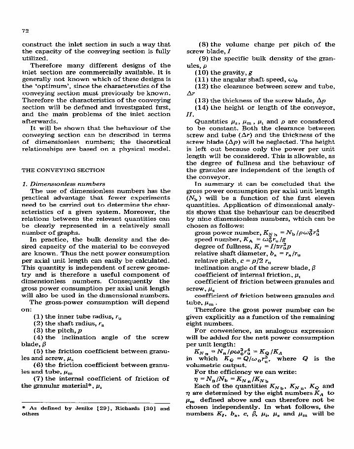
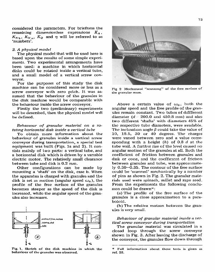
To obtain more information about the behaviour of granules inside a vertical screw conveyor during transportation, a special test equipment was built (Figs. la and 2). It con- sists mainly of two parts: a vertical tube, and a horizontal disk which is driven by a variable electric motor. The relatively small clearance between tube and disk is 0.2 mm.
Other configurations can be made by mounting a ‘shaft’ on the disk, case b. When the apparatus is charged with granules and the disk is set m motion (angular speed w,), the profile of the free surface of the granules becomes steeper as the speed of the disk is increased, while the angular speed of the gran- ules also increases.
Fig. 1. Sketch of the disk machine in which the behaviour of the granules was observed.
Fig 2 Mechamcal “scannmg” of the free surface of the granular mass.
Above a certain value of ws, both the angular speed and the free profile of the gran- ules remain constant_ Two tubes of dlffferent diameter (d = 200.0 and 450.8 mm) and also two different ‘shafts’ with diameters 45% of the respective tube diameters, were available. The inclination angle p could take the value of 10, 18.5, 30 or 40 degrees. The charges were varied between zero and a value corre- sponding with a height (h) of 0.8 d at the tube wall. A further rise of the level caused no angular motion of the granules at all. Both the coefficient of friction between granules and disk or cone, and the coefficient of frictron between granules and tube, was approxrmate- ly 0.30-0.35. The contour of the free surface could be ‘scanned’ mechanically by a number of pins as shown in Fig. 2. The granular mate- rials used were spinach, millet and rape seed_ From the experiments the following conclu- sron could be drawnx:
(a) The profile of the free surface of the granules is a close approximation to a para- boloid.
(b) The relative motion between the gran- ules is very small.
Behaviour of granular material inslde a ver- tical screw conveyor during transportation
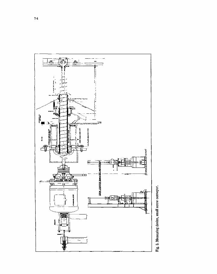
The granular material was circulated in a closed loop through the screw conveyor shown in Fig. 3. After leaving the discharge of the conveyor, the granules flow down through
* Full information about these tests is given m ref. 28.
74
75
sectlqn A- A
-3 A
parabola
pressure equals
static bead
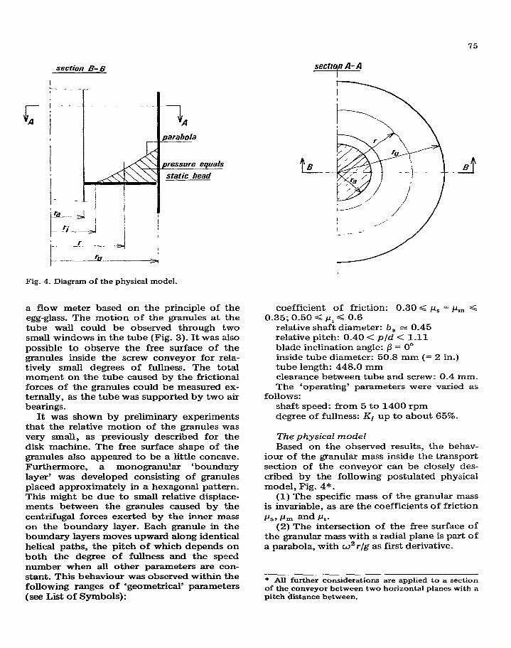
Fig. 4. Diagram of the physical model.
a flow meter based on the principle of the egg-glass. The motion of the granules at the tube wall could be observed through two small windows in the tube (Fig. 3). It was also possible to observe the free surface of the granules inside the screw conveyor for rela- tively small degrees of fullness. The total moment on the tube caused by the frictional forces of the granules could be measured ex- ternally, as the tube was supported by two air bearings.
It was shown by preliminary experiments that the relative motion of the granules was very small, as previously described for the disk machine. The free surface shape of the granules also appeared to be a little concave. Furthermore, a monogranular ‘boundary layer’ was developed consisting of granules placed approximately in a hexagonal pattern. This might be due to small relative displace- ments between the granules caused by the centrifugal forces exerted by the inner mass on the boundary layer. Each granule in the boundary layers moves upward along identical helical paths, the pitch of which depends on both the degree of fullness and the speed number when all other parameters are con- stant. This behaviour was observed within the following ranges of ‘geometrical’ parameters (see List of Symbols):
_-f B
coefficient of friction: 0.30 < I_r, = Pm < 0.35; 0.50 =G p1 =G 0.6
relative shaft diameter: b, * 0.45 relative pitch: 0.40 < p/d < 1.11 blade inclination angle: p = O” inside tube diameter: 50.8 mm (= 2 in.) tube length: 448.0 mm clearance between tube and screw: 0.4 mm. The ‘operating’ parameters were varied as
followsr shaft speed: from 5 to 1400 rpm degree of fullness: K1 up to about 65%.
The physical model Based on the observed results, the behav-
iour of the granular mass inside the transport section of the conveyor can be closely des- cribed by the following postulated physical model, Fig. 4*.
(1) The specific mass of the granular mass is invariable, as are the coefficients of friction
CLJY Pm and ~z- (2) The intersection of the free surface of
the granular mass with a radial plane is part of a parabola, with u2r/g as first derivative.
* All further considerations are applied to a section of the conveyor between two horizontal planes with a pitch &stance between.
76
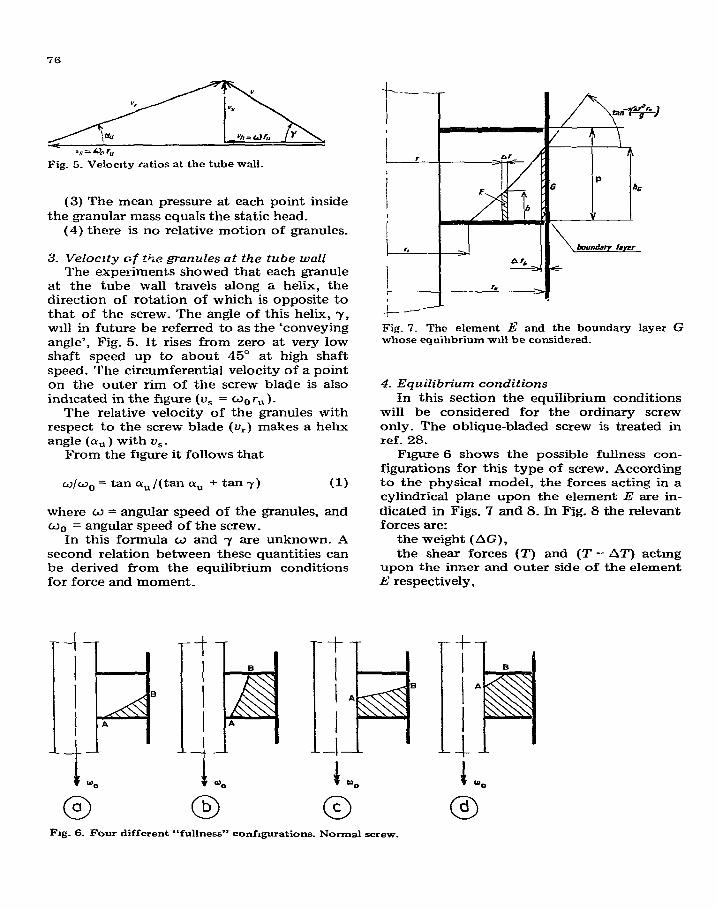
Fig. 5. Velocity ratios at the tube wall.
(3) The mean pressure at each point inside the granular mass equals the static head.
(4) there is no relative motion of granules.
3. Velocrty cf t&e granules at the tube wall The experiments showed that each granule
at the tube wall travels along a helix, the direction of rotation of which is opposite to that of the screw. The angle of this helix, y, ~111 in future be referred to as the ‘conveying angle’, Fig. 5. It rises from zero at very low shaft speed up to about 45” at high shaft speed. The circumferential velocity of a point on the outer rim of the screw blade is also indicated in the figure (u, = wOrU)_
The relative velocity of the granules with respect to the screw blade (u,) makes a helix angle (cuti) with u,.
From the figure it follows that
w/w0 = tan P, /(tan ciU -+ tan y) (1)
where o = angular speed of the granules, and w 0- - angular speed of the screw.
In this formula w and y are unknown. A second relation between these quantities can be derived from the equilibrium conditions for force and moment.
0 a 0 b
Fig. 7. The element E and the boundary layer G whose equihbrium ~111 be considered.
4. Equilibrium conditions
In this section the equilibrium conditions will be considered for the ordinary screw only. The oblique-bladed screw is treated in ref. 28.
Figure 6 shows the possible fullness con- figurations for this type of screw. According to the physical model, the forces acting in a cylindrical plane upon the element E are in- dicated in Figs. 7 and 8. In Fig. 8 the relevant forces are:
the weight ( AG), the shear forces (7’) and (T -- AT) actmg
upon the inner and outer side of the element E respectively,
+1 I I
B
A
I -I H -1 00
0 C
t 00
0 d
Fig. 6. Four different “fullness” confxgurations. Normal screw.
-
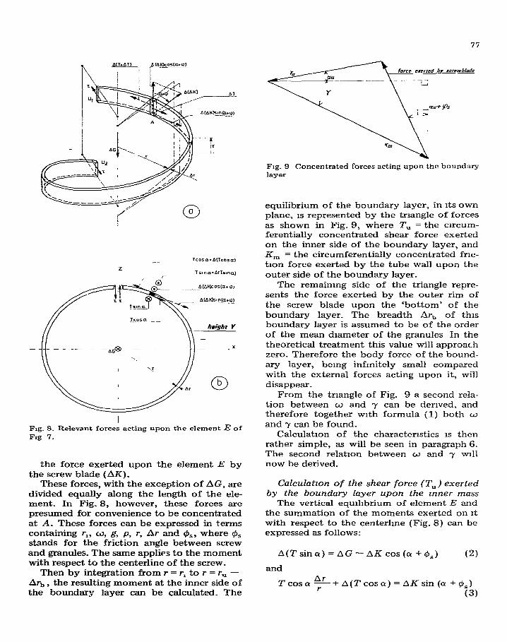
I Fig. 8. Relevant forces acting upon the element E of Fig 7.
the force exerted upon the element E by the screw blade (AK).
These forces, with the exception of AG, are divided equally along the length of the ele- ment_ In Fig. 8, however, these forces are presumed for convenience to be concentrated at A. These forces can be expressed in terms containing r,, w, g, p, r, Or and &,, where 9, stands for the friction angle between screw and granules. The same applies to the moment with respect to the centerline of the screw.
Then by integration from r = r, to r = r,1 - Ari-, , the resulting moment at the inner side of the boundary layer can be calculated_ The
Fig. 9 Concentrated forces acting upon the boundary layer
equilibrium of the boundary layer, in its own plane, IS represented by the triangle of forces as shown in Fig. 9, where T, = the cncum- ferentially concentrated shear force exerted on the inner side of the boundary layer, and
%n = the circumferentially concentrated frlc- tion force exerted by the tube wall upon the outer side of the boundary layer-
The remaining side of the triangle repre- sents the force exerted by the outer rim of the screw blade upon the ‘bottom’ of the boundary layer. The breadth Lsr, of this boundary layer is assumed to be of the order of the mean diameter of the granules In the theoretical treatment this value will approach zero. Therefore the body force of the bound- ary layer, being infinitely small compared with the external forces acting upon it, will disappear_
From the triangle of Fig. 9 a second rela- tion between w and y can be derived, and therefore together with formula (1) both o and y can be found.
Calculation of the characteristics IS then rather simple, as will be seen in paragraph 6. The second relation between w and y will now be derived_
Calculation of the shear force (T,) exerted by the boundary layer upon the Inner mass
The vertical equihbrium of element E and the summation of the moments exerted on It with respect to the centerline (Fig. 8) can be expressed as follows:
A(Tsine)=AG-AKcos(rr+@,) (2)
and
Tcosa$+A(Tcoscr)=AKsin((Y+oS)
(3)
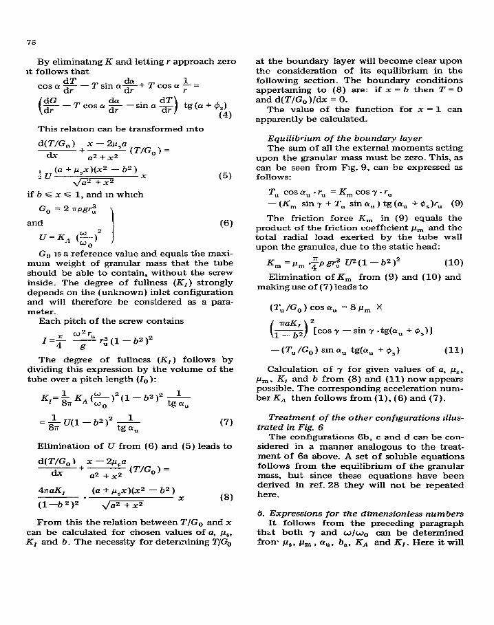
By eliminating K and letting r approach zero it follows that
dT da 1 cos cx dr - T sin CX-+ T cos CY 7 =
dr dG --Tcosr*F-sinolg dr
This relation can be transformed mto
d(T/G,) + x - 2p,a
dx a2 + x2 (T/G,) =
iv (a + pSx)(xz - b2)
J_ x (5)
ifb<x< 1,andmwhrch
G, = 2 rrpgrz
and \ (6)
G,, is a reference value and equals the maxi- mum weight of granular mass that the tube should be able to contain, without the screw inside. The degree of fullness (K,) strongly depends on the (unknown) inlet configuration and will therefore be considered as a para- meter.
Each pitch of the screw contains
I=$ $5 rz(l-b2)2
The degree of fullness (K, ) follows by dividing this expression by the volume of the tube over a pitch length (lo):
K,=&7K,(&)2(1-b2)2 &- u
=&u(l-b2)2 1 tg a,
(7)
Elimination of U from (6) and (5) leads to
d(T/G, ) + x - 2p,a
dx Q2 +x2 (T/G,) =
4iraK, (a + /J,x)(x~ - b2)
(l-b2)2 - x
&=3 (8)
From this the relation between T/G,-, and x can be calculated for chosen values of a, pS. KI and b. The necessity for determining T/G,
at the boundary layer will become clear upon the consideration of its equilibrium in the following section. The boundary conditions appertaining to (8) are: if x = b then T = 0 and d( T/G, )/dx = 0.
The value of the function for x = 1 can apparently be calculated.
Equilibrium of the boundary layer The sum of all the external moments acting
upon the granular mass must be zero. This, as can be seen from Fig. 9, can be expressed as follows:
T,, cos ay, - rU =K,cosy-r,
- (K, sin y + T, sin LY,, ) tg (a, + @,)I-,, (9)
The friction force K, in (9) equals the product of the friction coefficient pm and the total radial load exerted by the tube wall upon the granules, due to the static head:
Km=& -$grz ?P(l- b2)2 (10)
Elimination of K, from (9) and (IO) and making use of (7) leads to
(T,/G,) cosa, = SPY x
(s)‘[cosT -sin? -tg(a, +@,)I
- W, 1% 1 sin au tg&, + 0,) (11)
Calculation of y for given values of a, P,, i_c, , KI and b from (8) and (11) now appears possible. The corresponding acceleration num- ber KA then follows from (l), (6) and (7).
Treatment of the other configurations &.zs- trated in Fig. 6
The configurations 6b, c and d can be con- sidered in a manner analogous to the treat- ment of 6a above. A set of soluble equations follows from the equilibrium of the granular mass, but since these equations have been derived in ref. 28 they will not be repeated here.
5. Expressions for the dimensionless numbers It follows from the preceding paragraph
thit both -r and o/w,-, can be determined
front P,, pm, a,, b,, KA and KI . Here it will
79
be demonstrated that the dimensionless num- bers can also be expressed in the same quanti- ties.
For practical reasons it is attractive to con- sider the speed number KA (= o. rz /g) as an independent quantity, the remaming ones being parameters_
Capacity number, K,
Q= v I -=wrU tan-y
KIIO ‘P
- = srwK, tan yrt P
so
K Q = Q =i& )K tany wOr:
WO I (12)
Number for the nett power consumption,
KNl-4 The nett power consumption per axial
length of the conveyor is
N,= Qpg or, using (12)
N, =KQ”or;Pg
and thus
(13)
Number for the gross power consumption, K Nb
The gross power consumption equals the product of shaft speed and the moment ex- erted on the granules per unit length of tuber
N,, = moM” P
where M, represents the tube moment over a pitch length.
Substituting M, = K, cos 7 r, and di- viding by pwg ri _
cos -)
KN~=~ y&x, 0 A
(14)
where Go represents the weight per pitch of a totally filled conveyor, when the volume of the screw itself is neglected, and thus equals 2apgrz. It therefore is a good reference quan- tity, as mentioned before. Each configuration
of Fig. 6 has a corresponding expression for
KKI that can easily be calculated from the static head at the tube wall.
F Determination of the theoretical charcc- Cerhstics
The characteristics can now be calculated easily -using the developed theories. It can be concluded on physical grounds that the rela- tion between the “operational numbers” (paragraph 1) IS fully determined when b,( =
r,/rU ), c (= ~12 rU), P, AL, II, are known, and the degree of fullness (KI) is a parameter. This is confirmed by the formulae of paragraphs 4 and 5.
If the above-mentioned constant quantities are fixed, the calculation scheme used for the configuration of Fig. 6(a) is as follows:
1. choose K1, 2. choose b(=r,/r, ), 3. calculate U [= KA (w/o~)~ ] from 1 and
2, 4. calculate y by substitution of U in the
equation of the moment-eqmhbrium, 5. calculate w/w0 by eqn. (1). 6. calculate the shaft speed number,
KA = U/(W/WO)~, '7. calculate KQ, KN,.,. KN,, with the ex-
pressions derived in paragraph 5. The procedure can then be started again at
point 2 with another value of b, etc. until enough points are known. Calculation for an entirely filled conveyor starts with a choice of U at point 3 of the above procedure and continues in the same way.
In the original work [28], the parameters had the following values:
Relative shaft diameter, b, = d 0.2 = 0.45 Relative pitch, c =p/d = 0.4, 0.7 and 1.0 Coefficient of sliding friction between
screw and granular mass, p, = 0.3 and 0.4 Coefficient of sliding friction between tube
and granular mass, pm = 0.3 and 0.4 Degree of fullness, KI = 0.2, 0.4, 0.6 and
0.8 Acceleration number, KA varying from
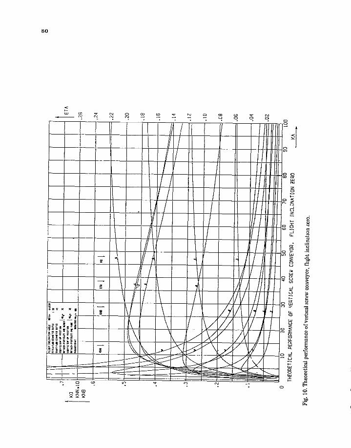
zero up to 100 thus resulting in 12 graphs of the type of Fig. 10, which are closely approached in most practical cases. Another set (of 24 graphs) was obtained by calculations on an oblique-bladed screw with 15” and 30” inclination of the screw blade.
.24
THEORETICAL
PERFORMANCE
OF 'IERTICAL SCREW
CONVEYOR,
FLIGHT fNCLlNATlON
ZERO
A
10.
The
oret
ical
per
form
ance
of
vert
wl
scre
w c
onve
yor,
fhg
ht i
nclin
atio
n m
ro.
- __
.-
-.
-
“.
LI
.,
. .
u-
. .^
..
L
- r.
-
7 -
7 I.
.- -
. I
u.-
81
7. Experimental results The small model of the screw conveyor in
our laboratory consisted of a brass tube and screws machined from solid steel bars. Ten different screws were made: 5 normal screws and 5 screws with a blade inclination of 30”. Both groups had the following pitches: 19, 32, 40,48 and 56 mm. The shaft diameter for all screws was 19 mm. Tests were carried out with spinach, rape and millet.
A larger specially designed experimental set-up was also built, in which screws of up to 256 mm diam. could be used. In this installa- tion tests were carried out with screws of 162 mm, grain and Russian peas being the material transported in recirculation_ The agreement between the calculated and the measured values of CdpaCity and power con- sumption was within 5 and 9% respectively.
S Summary of the most important conclu- sions
The conclusions that follow here are based upon the complete investigations carried out and cannot be derived wholly from this arti- cle_ The conclusions hold within the field in- vestigated in which the relevant quantities were varied as follows:
Relative pitch (p/d): from 0.37 up to 1.12 Inclination of screw blade: from 0” up to
30” Relative shaft diameter, b,: approx. 0.45
fixed value Tube diameters: 50.8 and 162.0 mm Coefficients of friction ps and pm in the
combinations: ps = pm = 0.3 and 0.4; CL== 0.3,
l&n = 0.4; and ps = 0.4, pm = 0.3 Degree of fullness, K,: from 0 up to 0.80 -4cceleration number, KA : from 0 up to
100 Internal coefficient of friction of the gran-
ular material, p,: 0.55 < p, < 0.60
General (1) The vertical screw conveyor, if provided
with a well functioning inlet, is, from a tech- nical point of view, an excellent means for the continuous transport of granular materials as long as the following conditions are fulfilled:
(a) Size and shape of the granules should be such that both leakage through, and jamming in, the slot between screw-blade and tube is avoided. However, most industrial equipment has, for practical purposes, a clearance larger
than the particle size, to avoid particle dam- age. As a consequence the capacity is slightly decreased.
(b) The acceleration number may not fall below a certain (the critical) value.
(c) In order to prevent backflow, relative to the main bulk of the particles closest to the shaft. the coefficient of internal friction of the granular material may not be too low, depending on the coefficients of sliding fric- tion of screw and tube (,u, and Y, )_
(2) The conveying part of the screw will be able to transport the amount of granular material that it contains up to almost perfect fullness_ This is an important conclusion, since for partly filled screws operating at saturation it was not, up till now, known if the restriction in capacity was caused by the inlet or the conveying part itself. However, see also conclusion (3) _
(3) Based upon power efficiency, fillings greater than 75% of maximum should be avoided _
(4) Apphcation of oblique-bladed screws has no advantages over normal ones; the screw characteristics are hardly influenced by this.
(5) It can be proved theoretically that, although negligible in practical cases, the rela- tive backflow of granules at the shaft is less for oblique-bladed screws than for normal ones.
(6) Pulverization caused by shearing of
granules between screw blade and tube at the inlet can be successfully prevented by fasten- ing a displacement body locally on the blade periphery.
(7) The theory of the “smgle granule” or point-mass [1,2,6,7,9] leads for ~_r, = pm and fillings of less than 60% to errors at the maxi- mum of 10 and 16% for capacity and effi- ciency respectively.
Capacity number and efficiency The mfluence of K_,,, KI, p/d, j3, b,, pm and
,u, on K, and n is mentioned hereunder. (1) Acceleration number KA
KQ (= Q/wOrz ) originally increases with the acceleration number KA (= w~ru /g)_ In the investigated range at K_., = 20, K, had already increased by up to about 80% of its value at KA = 100.
77 increases strongly with the acceleration number KA , passes through a maximum and then decreases slowly. The maxima are con-
82
centrated around common practical values of KA (CQ. 10-25) for pitch-diameter ratios of 0.7.
(2) The fullness, KI K, is almost proportional with the degree
of fullness (KI) _ q keeps constant approximate- iy up to KI = 0.6 and decreases then to about 60% of this value at Kl = 0.8.
(3) The relative pitch (p/d) K, mcreases approximately linearly with
pJd if 0 < pjd < 1. When pld > 1 the mcrease is less marked_ If the friction coefficients at tube and screw are equal between 0.3 and 0.4, which holds for most cases, the efficiency curves have their maxima for values of p/d between 0.6 and 0.8.
(4) Inclination angle of the screw blade K, is almost independent of the blade-
inclination angle (6). q decreases somewhat when /3 increases (a few percent when @ in- creases from 0” up to 30”).
(5) Relative shaft diameter, b, K, and 7) are only shghtly influenced by
varying the shaft diameter between 0.25 and 0.45.
(6) The friction coefficients pS and pm K, is virtually independent of &., but is
influenced appreciably by pS_ Variation of per, from 0.3 up to 0.4 leads to a decrease in K, of about 10%.
The efficiency depends strongly on pS; the influence of pm is negligible.
Decrease of p, leads to increase of the effi- ciency.
nlnax = 15% when p, = 0.4; this amounts = 20% when cc, = 0.3.
(7) The maximum efficiency As the coefficient between screw and gran-
ules (p,) in most practical cases is not below 0.3, the maximum efficiency that can be real- ized will not exceed = 20%.
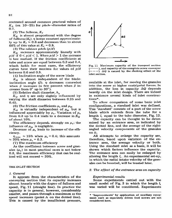
Q t
Fag. 11 Maximum capacity of the transport section -), and capacity of the complete screw conveyor
I---) AQ - 1s caused by the choking effect of the inlet section.
available at the inlet, for moving the granules into the screw at higher centripetal forces. In addition, the loss in capacity AQ depends heavily on the inlet design. There are indeed in existence several kinds of inlet construc- tions* _
To allow comparison of some basic inlet configurations, a standard inlet was defined. This ‘standard’ consists of a part of the screw blade which extends from the tube for a length 1, equal to the tube diameter, Fig. 12.
The capacity can be thought to be deter- mined by an entrance area, as indicated by the dotted line, and the average of the right- angled velocity components of the granules on it.
All attempts to enlarge the capacity are, therefore, based upon variation of the en- trance area, the average velocity or both. IJsing the standard mlet as a basis, it will be shown which factors influence the capacity. The entrance area can easily be enlarged by altering the length I,_ An experimental set-up, in which the radial intake velocity of the gran- ules can be boosted, will be treated later.
THE INLET SECTION
2. The effect of the entrance area on capacity 1. General
It appears from the characteristics of the conveying section that its capacity increases almost lmearly with the degree of fullness and speed, Fig. 11 (straight line). In practice the capacity is in general, however, considerably smaller, and passes through a maximum as the speed increases (point A on the dotted line). This is caused by the insufficient pressure,
Experimental results Some experiments carried out with the
small model of Fig. 3 in which the length li was varied will be considered. Experiments
* ‘Improvements’ by application of auxiliary eqmp- ment such as separately driven feed screws are not considered here.
83
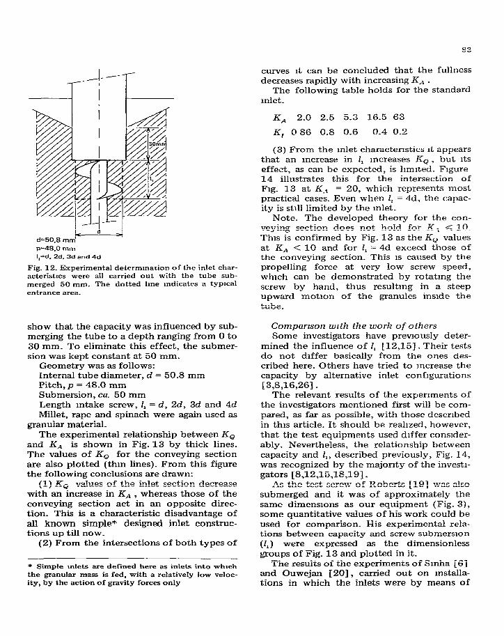
d=50,8 ,,-I-,~ ~=48,0mm
I,=d,Zd,Sd and4d
Fig. 12. Experimental determmarion of the inlet char- acteristlcs were all carried out with the tube sub- merged 50 mm. The dotted lme Indicates a typlcal entrance area.
show that the capacity was influenced by sub- merging the tube to a depth ranging from 0 to 30 mm. To eliminate this effect, the submer- sion was kept constant at 50 mm.
Geometry was as follows: Internal tube diameter, d = 50.8 mm Pitch, p = 48.0 mm Submersion, ca_ 50 mm Length intake screw, I, = d, 2d, 3d and 4d Millet, rape and spinach were again used as
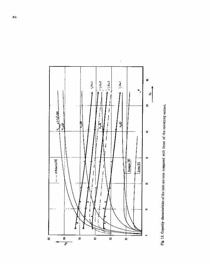
granular material_ The experimental relationship between Ko
and KA is shown in Fig. 13 by thick lines. The values of Ko for the conveying section are also plotted (thin lines)_ From this figure the following conclusions are drawn:
(1) KQ values of the inlet section decrease with an increase in KA , whereas those of the conveying section act in an opposite direc- tion. This is a characteristic disadvantage of all known simple* designed inlet construc- tions up till now-
(2) From the intersections of both types of
* Simple 1n1et.s are defined here as inlets into whxh the granular mass is fed, with a relatively low veloc- ity, by the action of gravity forces only
curves it can be concluded that the fullness decreases rapidly with increasing K,% -
The following table holds for the standard inlet.
K-4 2.0 2.5 5.3 16.5 63
K, 0 86 0.8 0.6 0.4 0.2
(3) From the mlet characteristics it appears that an increase in 1, mcreases I&, but its effect, as can be expected, is hmited. Figure 14 illustrates this for the intersection of Fig. 13 at K_, = 20, which represents most practical cases. Even when I, = 4d, the capac- ity is still limited by the inlet.
Note. The developed theory for the con- veying section does not hold for K, < 10. This is confirmed by Fig. 13 as the KQ values at KAa < 10 and for I, = 4d exceed those of the conveying section. This is caused by the
propelling force at very low screw speed, which can be demonstrated by rotating the screw by hand, thus resultmg in a steep upward motion of the granules inside the tube.
Comparrson wrth the work of others Some investigators have previously deter-
mined the influence of I, [12,15]. Their tests do not differ basically from the ones des- cribed here. Others have tried to increase the capacity by alternative inlet configurations [3,8,16,26].
The relevant results of the experiments of the investigators mentioned first will be com- pared, as far as possible, with those described in this article. It should be realized, however, that the test equipments used differ consider- ably_ Nevertheless, the relationship between capacity and I,, described previously, Fig_ 14, was recognized by the majority of the investi- gators [8,12,15,18,19].
As the test screw of Roberts [19] was also submerged and it was of approximately the same dimensions as our equipment (Fig. 3), some quantitative values of his work could be used for comparison_ His experimental rela- tions between capacity and screw submersion
(l,) were expressed as the dimensionless groups of Fig. 13 and plotted in it.
The results of the experiments of Smha [6] and Ouwejan 1201, carried out on mstalla- tions in which the inlets were by means of
84
\-
\
\
T
-iI P --
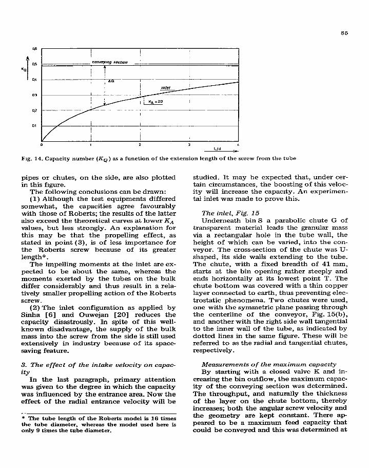
85
Fig. 14. Capacity number (Kg) as a function of the extension length of the screw from the tube
pipes or chutes, on the side, are also plotted in this figure.
The following conclusions can be drawn: (1) Although the test equipments differed
somewhat, the capacities agree favourably with those of Roberts; the results of the latter also exceed the theoretical curves at lower KA values, but less strongly. An explanation for this may be that the propelling effect, as stated in point (3), is of less importance for the Roberts screw because of its greater length* _
The impelling moments at the inlet are ex- pected to be about the same, whereas the moments exerted by the tubes on the bulk differ considerably and thus result in a rela- tively smaller propelling action of the Roberts screw _
(2) The inlet configuration as applied by Sinha [S] and Ouwejan [ZO] reduces the capacity disastrously. In spite of this well- known disadvantage, the supply of the bulk mass into the screw from the side is still used extensively in industry because of its space- saving feature.
3. The effect of the intake velocity on capac-
ity In the last paragraph, primary attention
was given to the degree in which the capacity was influenced by the entrance area. Now the effect of the radial entrance velocity will be
* The tube length of the Roberts model is 16 times the tube diameter, whereas the model used here is only 9 times the tube diameter.
studied. It may be expected that, under cer- tain circumstances, the boosting of this veloc- ity will increase the capacity. An experimen- tal inlet was made to prove this.
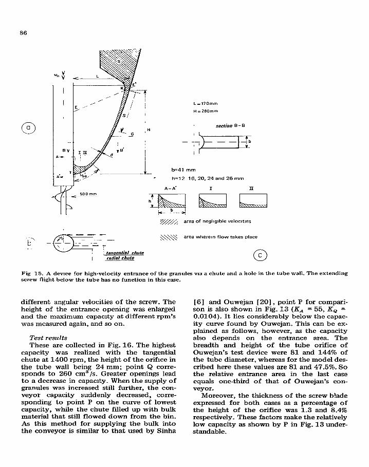
The inlet, Fig_ 15 Underneath bin S a parabolic chute G of
transparent material leads the granular mass via a rectangular hole in the tube wall, the height of which can be varied, into the con- veyor. The cross-section of the chute was U- shaped, its side walls extending to the tube. The chute, with a fixed breadth of 41 mm, starts at the bin opening rather steeply and ends horizontally at its lowest point T. The chute bottom was covered with a thin copper layer connected to earth, thus preventing elec- trostatic phenomena. Two chutes were used, one with the symmetric plane passing through the centerline of the conveyor, Fig. 15(b), and another with the right side wall tangential to the inner wall of the tube, as indicated by dotted lines in the same figure. These will be referred to as the radial and tangential chutes, respectively.
Measurements of the maximum capacrty By starting with a closed valve K and in-
creasing the bin outflow, the maximum capac- ity of the conveying section was determined. The throughput, and naturally the thickness of the layer on the chute bottom, thereby increases; both the angular screw velocity and the geometry are kept constant. There ap peared to be a maximum feed capacity that could be conveyed and this was determined at
86
L =l?Omm
H=280mm
b=41 mm
h=l2 16,20,24 and 26 mm
A
h’ Y
Fig 15. A devtce for high-velocity entrance of the granules wa a chute and a hole in the tube wall. The extending screw flight below the tube has no function in this case.
different angular velocities of the screw. The height of the entrance opening was enlarged and the maximum capacity at different rpm’s
was measured again, and so on.
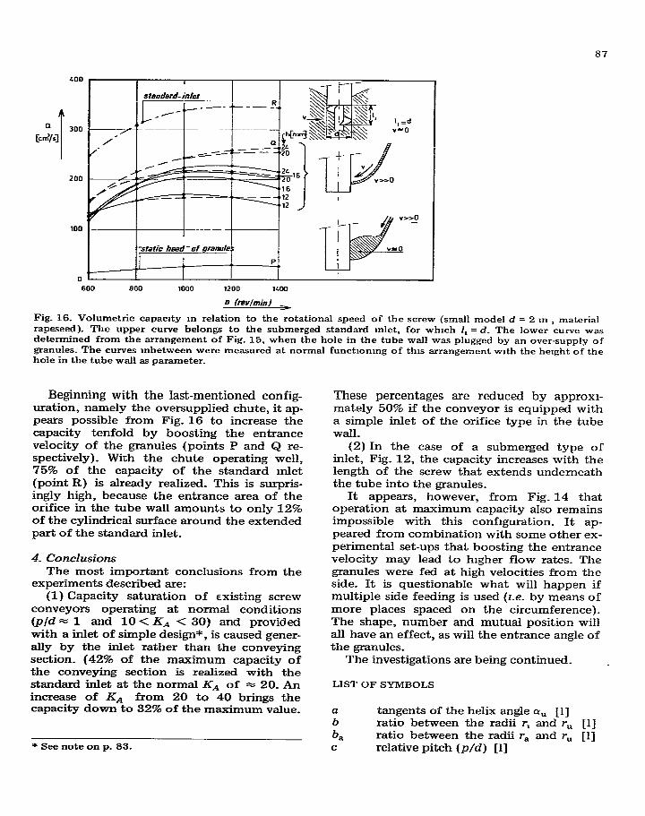
Test results These are collected in Fig. 16. The highest
capacity was realized with the tangential chute at 1400 rpm, the height of the orifice in the tube wall being 24 mm; point Q corre- sponds to 260 cm3/s. Greater openings lead to a decrease in capacity. When the supply of granules was increased still further, the con- veyor capacity suddenly decreased, corre- sponding to point P on the curve of lowest capacity, while the chute filled up with bulk material that still flowed down from the bin. As this method for supplying the bulk into the conveyor is similar to that used by Sinha
[6] and Ouwejan [20], point P for compari- son is also shown in Fig. 13 (KA = 55, Ko = 0.0104). It lies considerably below the capac- ity curve found by Ouwejan. This can be ex- plained as follows, however, as the capacity also depends on the entrance area. The breadth and height of the tube orifice of Ouwejan’s test device were 81 and 144% of the tube diameter, whereas for the model des- cribed here these values are 81 and 47.5%. So the relative entrance area in the last case equals one-third of that of Ouwejan’s con- veyor.
Moreover, the thickness of the screw blade expressed for both cases as a percentage of the height of the orifice was 1.3 and 8.4% respectively. These factors make the relatively low capacity as shown by P in Fig. 13 under- standable.
8’7
600 600 1000 1200 x00
n ffWminl
Fig. 16. Volumetric capacrty m relation to the rotational speed of the screw (small model d = 2 m , material rapeseed). The upper curve belongs to the submerged standard Inlet, for which I, = d. The lower curve was determined from the arrangement of Fig. 15, when the hole in the tube wall was plugged by an over-supply of granules_ The curves mbetween were measured at normal functionmg of this arrangement with the height of the hole in the tube wall as parameter_
Beginning with the last-mentioned config- uration, namely the oversupplied chute, it ap- pears possible from Fig. 16 to increase the capacity tenfold by boosting the entrance velocity of the granules (points P and Q re- spectively). With the chute operating well, 75% of the capacity of the standard mlet (point R) is already realized_ This is surpris- ingly high, because the entrance area of the orifice in the tube wall amounts to only 12% of the cylindrical surface around the extended part of the standard inlet.
4. Conclusions
The most important conclusions from the experiments described are:
(1) Capacity saturation of existing screw conveyors operating at normal conditions (p/d = 1 and 10 < KA < 30) and provided with a inlet of simple design*, is caused gener- ally by the inlet rather than the conveying section. (42% of the maximum capacity of the conveying section is realized with the standard inlet at the normal KA of = 20. An increase of KA from 20 to 40 brings the capacity down to 32% of the maximum value.
* See note on p. 83.
These percentages are reduced by approxl- mately 50% if the conveyor is equipped with a simple inlet of the orifice type in the tube wall.
(2) In the case of a submerged type of inlet, Fig. 12, the capacity increases with the length of the screw that extends underneath the tube into the granules.
It appears, however, from Fig. 14 that operation at maximum capacity also remains impossible with this configuration. It ap- peared from combination with some other ex- perimental set-ups that boosting the entrance velocity may lead to higher flow rates. The granules were fed at high velocities from the side. It is questionable what will happen if multiple side feeding is used (2-e. by means of more places spaced on the circumference)_ The shape, number and mutual position will all have an effect, as will the entrance angle of the granules.
The investigations are being continued_
LIST OF SYMBOLS
a tangents of the helix angle Q, [l] b ratio between the radii r, and r, [l]
b, ratio between the radii r, and r,, [l] C relative pitch (p/d) [1]
88
d G
g I
IO
KA
KI K Imah KIT2
K Nb
Khr ,,
KQ
Nb
Nil
r
‘a
r,
r”
T T u
vh
V,
VI.
X
cd
QU
/3
Y
rl
Cci
Pm
internal tube diameter [m] weight of the granular material [N] gravrty [m/s2 ] volume of granular material, voidage in- cluded, in the screw over a pitch length [m3 ] volume of the tube over a pitch length
Im3 1 ‘speed’ or acceleration number (wg r, /
g) El1 degree of fullness (I/IO) [l] maximum value of K1 = (1 -bz ) [l] force exerted by the tube on the granular material over a pitch length
WI number for the gross power consump- tion [l] number for the nett power consump- tion [l] capacity number [l] gross power consumption per axial unit length [N/s] nett power consumption per axial unit length [N/s] pitch [m] pressure between screw blade and granules [ N/m2 ] radius (ra < r < r, ) [m] shaft radius [m] distance of the granules nearest to the centerline [m] internal tube diameter [m] arbitrary quantity [several] shear force [N] velocity of granules at the tube wall
[m/s1 horizo 1ta.l component of v [m/s] relative velocity between granules and the screw blade at the tube wall [m/s] velocity of a circumferential point of the screw blade [m/s] vertical component of v [m/s] relative radius (r/r, ) [l] helix angle of the screw at radius r [l] helix angle of the screw at radius r,
113 blade inclination [l] angle of the helical path of the granu- les at the tube wall [l] efficiency of the transport section of a vertical screw conveyor 111 coefficient of internal friction of the granular mass [l] coefficient of sliding friction between tube and granular mass [1]
coefficient of sliding friction between screw and granular mass [l] specific bulk density of the granular mass [ kg/m3 ] internal friction angle of the granular mass [l] friction angle between tube and granular mass [l] friction angle between screw and granular mass Cl] angular velocity of granular mass[l/s] angular velocity of shaft [l/s]
REFERENCES
1
2
3
E.M. Gutyar, Trudy Mosk. Inst. Mekh. Elekt. Khoz., 2 (1956) p_ 102-122. M. Thusing, Die Fbrderschnecke als stetiger Fdr- derer fur Schiitt- und Stuckgut, Fordem Heben, (Ma]) (1959) 302-304. R.M. Pear-t, Experimental vertical augers for a s.110 unloader. Bull. 631, Agr. Expt. Sta , Umv. Illi- nois, 1958.
4 W-M. Renan and SM. Henderson, Performance
5
6
7
8
9
10
11
12
13
14
15
characte&ics of inclined screw conveyors, Agr. Eng., (Aug.) (1959) 45@-452. C. Ephremides, Schneckenforderer mit geschiosse- nem zylindrischen Trog, F-drdern Heben, (Sept.) (1959) 614-615. G.L. Smha, Untersuchungen zum Fordergang beim senkrechten Schneckenfbrderer. Diss., T-H. Hannover, 1959. A. Baks and W.L.M. Schmid, Vertrkaai transport met schroeftransporteurs, Poiytech. Tijdschr. A, (februari) (1960) 164-174. A_ Konig and U. Riemann, Untersuchungen am senkrechten Schneckenforderer, Landtech. Forsch., 10 (2) (1960), 45-52. A. Vieriing and G-L. Sinha, Untersuchungen zum Fordergang beim senkrechten Schneckenforderer, Fordem Heben, (Aug.) (196G) 587-592. 1-J. Ross, The forces acting in particle stacks and the capacities of enclosed screw conveyors, Ph.D. Thesis, Purdue Univ., 1960. 1-J. Ross and G.W. Isaacs, Forces acting in stacks of granular material (parts 1 and 2). Trans. ASAE, (1961) 92-96. J-R. O’CaIIaghan and T-A. FaIlon, Performance of vertical screw conveyors, J. Agr. Eng. Res., 6 (1961) 87-9’7. G_N_ Stevens, Performance tests in experimental auger conveyors, J. Agr. Eng. Res., 7 (1962) 47-60. G-M. White, L-A. Schaper, 1-J. Ross and G-W_ Isaacs, Performance characteristics of enclosed screw conveyors, handling shelled corn and soy- beans, Purdue Univ. Res. Bull. 740,1962. A.W. Roberts and A.M. Willis, Performance of grain augers, Proc. Inst. Mech. Engrs., 176 (1962) 165-194.
89
16 J-R. O’Callaghan, Some experiments on the in- take process in a vertical screw conveyor, J. Agr. Eng. Res., 7 (1962) 282-287.
17 G.E. Rehkugler, Practical and theoretical perfor- mance characteristics of auger conveyors, MSc. Thesis, Cornell Univ., 1958.
18 G.E. Rehkugler and L.L. Boyd, Dimensional analysis of auger conveyor operation, Trans. ASAE, (1962) 98-102.
19 A.W. Roberts, An investigation of gram vortex motion with relation to the performance withm vertical grain augers. Proc. Inst. Mech. Engrs.. 176 (8) (1963164) 165--194.
20 J.A. Ouwejan, Ondenoek betreffende vertikale schroeftransporteurs. Opdracht doktoraal ex- amen, TX. Eindhoven, 1963
21 J.D. Bush, All about screw conveyors, Rock Prod.. (July) (1964) 67-71, 98, 100.
22 L.F. Bouse, L.G. Schoenleber and J.G. Porter- field, Screw conveyor capacity and castorseed damage, Trans. ASAE, (1964) 152-156
23 G.E. Rehkugler, Screw conveyors, state of art, Trans. ASAE, (1967) 615-618.
24 L.M Kucyn and A.M. Gngonev, Traktorl sel- chozmaschim. 0 Proizwobitelnostl Vertrkalnich Schnekow USSR, 4 (196s).
25 S Bdttcher, Eme allgememe Analyse der Auf- wartsfordering eines Einzelkorpers m Schnecken- forderern beliebiger Neigung, ver. Deut Ingr. Z., 105 (1963) (14) 581-593. (16) 663-671, (18) 743-754.
26 Lars-Gunnar N&son, On the vertical screw con- veyor for non-cohesive bulk materials, Acta Poly- tech. Stand Mech Eng Ser , 64 (1971)
27 F.J.C Rademacher, Some aspects of the charac- teristics of vertical screw conveyors for granular material, Mech Commun , 1 (1) (1972). Tech- nrsche Hogeschool, Twente, Enschede (Ned.).
28 F.J.C. Rademacher, De vertikale schroeftrans- porteur, Doctor’s Thesis, Twente Univ of Tech- nology, 1972.
29 A-W_ Jenike. Gravity flow of bulk sollds, Bull. 108, Eng. Expt. Sta., Utah State Umv., 1962.
30 J.C Richards, The Storage and Recovery of Par- tlculate Sohds, Inst. Chem. Eng., London, 1966.