Embed Size (px)
Citation preview
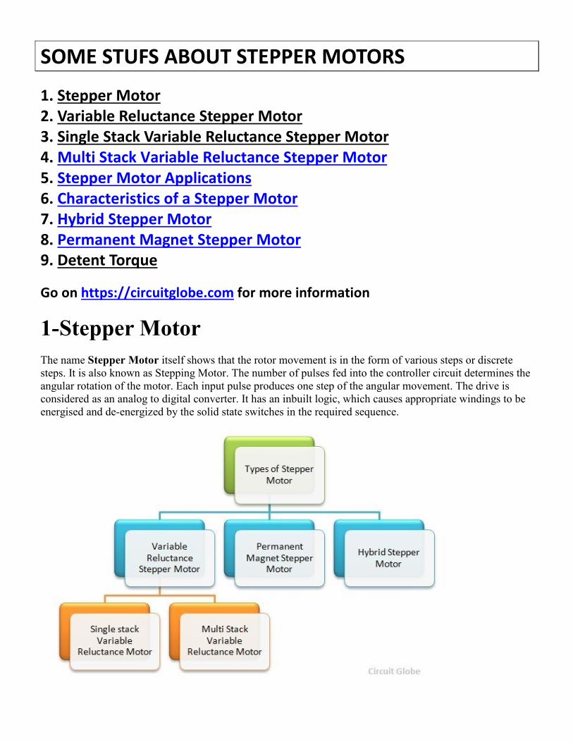
SOME STUFS ABOUT STEPPER MOTORS
1. Stepper Motor
2. Variable Reluctance Stepper Motor
3. Single Stack Variable Reluctance Stepper Motor
4. Multi Stack Variable Reluctance Stepper Motor
5. Stepper Motor Applications
6. Characteristics of a Stepper Motor
7. Hybrid Stepper Motor
8. Permanent Magnet Stepper Motor
9. Detent Torque
Go on https://circuitglobe.com for more information
1-Stepper Motor
The name Stepper Motor itself shows that the rotor movement is in the form of various steps or discrete
steps. It is also known as Stepping Motor. The number of pulses fed into the controller circuit determines the
angular rotation of the motor. Each input pulse produces one step of the angular movement. The drive is
considered as an analog to digital converter. It has an inbuilt logic, which causes appropriate windings to be
energised and de-energized by the solid state switches in the required sequence.
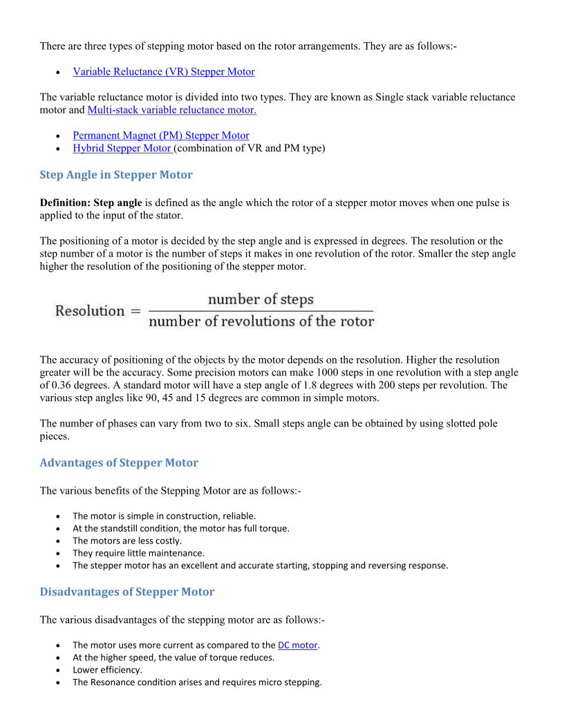
There are three types of stepping motor based on the rotor arrangements. They are as follows:-
Variable Reluctance (VR) Stepper Motor
The variable reluctance motor is divided into two types. They are known as Single stack variable reluctance
motor and Multi-stack variable reluctance motor.
Permanent Magnet (PM) Stepper Motor
Hybrid Stepper Motor (combination of VR and PM type)
Step Angle in Stepper Motor
Definition: Step angle is defined as the angle which the rotor of a stepper motor moves when one pulse is
applied to the input of the stator.
The positioning of a motor is decided by the step angle and is expressed in degrees. The resolution or the
step number of a motor is the number of steps it makes in one revolution of the rotor. Smaller the step angle
higher the resolution of the positioning of the stepper motor.
The accuracy of positioning of the objects by the motor depends on the resolution. Higher the resolution
greater will be the accuracy. Some precision motors can make 1000 steps in one revolution with a step angle
of 0.36 degrees. A standard motor will have a step angle of 1.8 degrees with 200 steps per revolution. The
various step angles like 90, 45 and 15 degrees are common in simple motors.
The number of phases can vary from two to six. Small steps angle can be obtained by using slotted pole
pieces.
Advantages of Stepper Motor
The various benefits of the Stepping Motor are as follows:-
The motor is simple in construction, reliable.
At the standstill condition, the motor has full torque.
The motors are less costly.
They require little maintenance.
The stepper motor has an excellent and accurate starting, stopping and reversing response.
Disadvantages of Stepper Motor
The various disadvantages of the stepping motor are as follows:-
The motor uses more current as compared to the DC motor.
At the higher speed, the value of torque reduces.
Lower efficiency.
The Resonance condition arises and requires micro stepping.
At the high speed, the control is not possible.
2-Variable Reluctance Stepper Motor
The principle of Variable Reluctance Stepper Motor is based on the property of the flux lines which
capture the low reluctance path. The stator and the rotor of the motor are aligned in such a way that the
magnetic reluctance is minimum. There are two types of the Variable Reluctance Stepper Motor. They are as
follows
Single Stack Variable Reluctance Motor
Multi Stack Variable Reluctance Motor
Working of a Variable Reluctance Stepper Motor
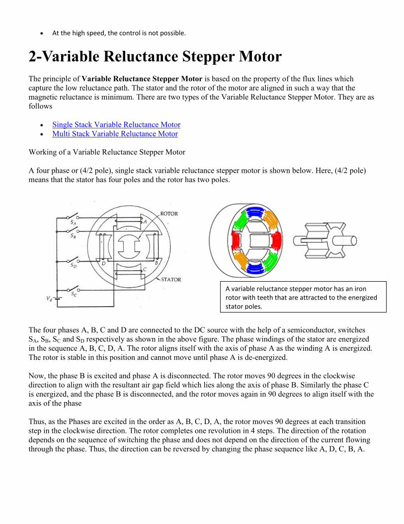
A four phase or (4/2 pole), single stack variable reluctance stepper motor is shown below. Here, (4/2 pole)
means that the stator has four poles and the rotor has two poles.
The four phases A, B, C and D are connected to the DC source with the help of a semiconductor, switches
SA, SB, SC and SD respectively as shown in the above figure. The phase windings of the stator are energized
in the sequence A, B, C, D, A. The rotor aligns itself with the axis of phase A as the winding A is energized.
The rotor is stable in this position and cannot move until phase A is de-energized.
Now, the phase B is excited and phase A is disconnected. The rotor moves 90 degrees in the clockwise
direction to align with the resultant air gap field which lies along the axis of phase B. Similarly the phase C
is energized, and the phase B is disconnected, and the rotor moves again in 90 degrees to align itself with the
axis of the phase
Thus, as the Phases are excited in the order as A, B, C, D, A, the rotor moves 90 degrees at each transition
step in the clockwise direction. The rotor completes one revolution in 4 steps. The direction of the rotation
depends on the sequence of switching the phase and does not depend on the direction of the current flowing
through the phase. Thus, the direction can be reversed by changing the phase sequence like A, D, C, B, A.
A variable reluctance stepper motor has an iron
rotor with teeth that are attracted to the energized
stator poles.
The magnitude of the step angle of the variable reluctance motor is given as
Where,
α is the step angle
ms is the number of stator phases
Nr is the number of rotor teeth
The step angle is expressed as shown below.
Where, NS is the stator poles
The step angle can be reduced from 90 degrees to 45 degrees in a clockwise direction by exciting the phase
in the sequence A, A+B, B, B+C, C, C+ D, D, D+A, A.
Similarly, if the sequence is reversed as A, A+D, D, D+C, C, C+B, B, B+A, A, the rotor rotates at step angle
of 45 degrees in the anticlockwise direction.
Here, (A+B) means that the phase windings A and B both are energized together. The resultant field is the
midway of the two poles. i.e. it makes an angle of 45 degrees with the axis of the pole in the clockwise
direction. This method of shifting excitation from one phase to another is known as Microstepping.By using
Stepper Motor, lower values of the step angle can be obtained with numbers of poles on the stator.
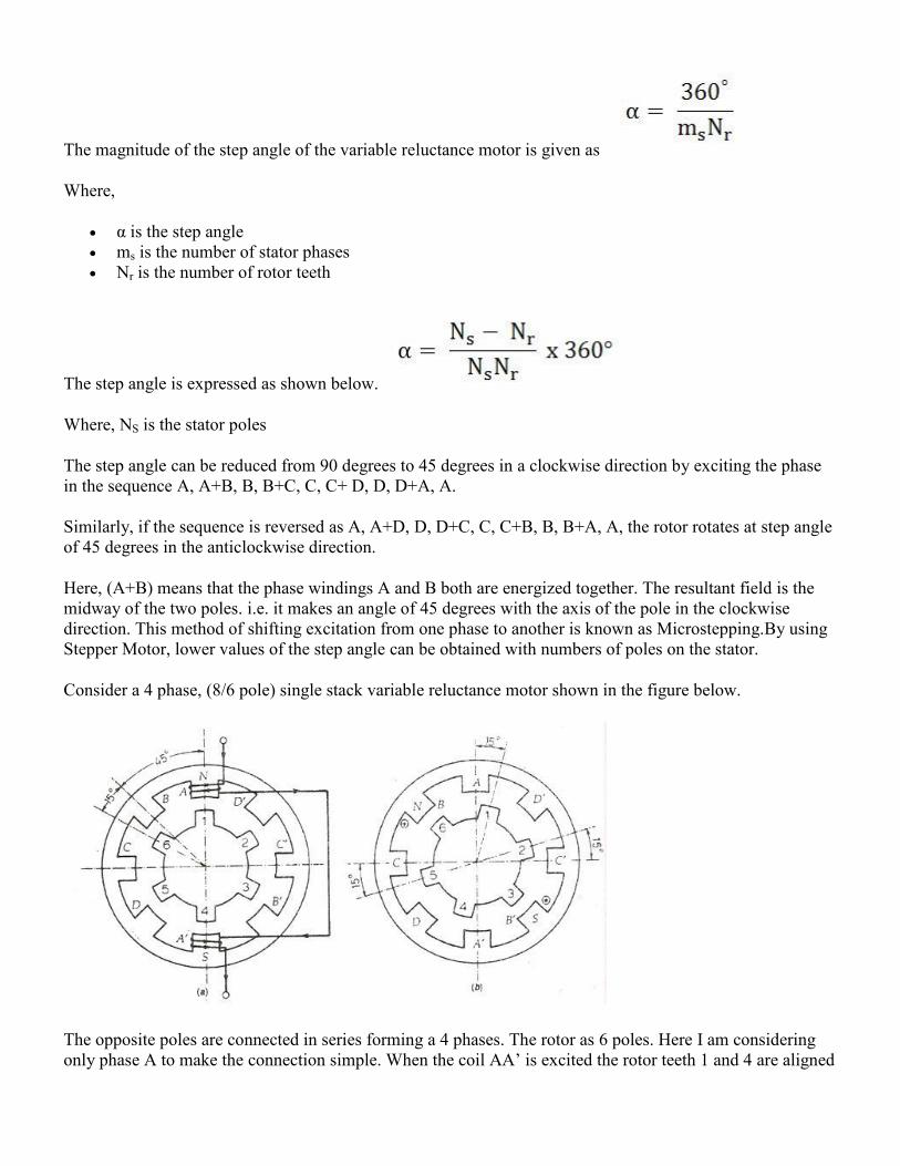
Consider a 4 phase, (8/6 pole) single stack variable reluctance motor shown in the figure below.
The opposite poles are connected in series forming a 4 phases. The rotor as 6 poles. Here I am considering
only phase A to make the connection simple. When the coil AA’ is excited the rotor teeth 1 and 4 are aligned
along the axis of the winding of the phase A. Thus, the rotor occupies the position as shown in the above
figure (a).
Now, the phase A is de-energized, and the phase winding B is energized. The rotor teeth 3 and 6 get aligned
along the axis of phase B. The rotor moves a step of phase angle of 15 degrees in the clockwise direction.
Further, the phase B is de-energized, and the winding C is excited. The rotor moves again 15⁰ phase angle.
The sequence A, B, C, D, A is followed, and the four steps of rotation are completed, and the rotor moves 60
degrees in clockwise direction. For one complete revolution of the rotor 24 steps are required. Thus, any
desired step angle can be obtained by choosing different combinations of the number of rotor teeth and stator
exciting coils.
3-Single Stack Variable Reluctance Stepper Motor
A single stack variable reluctance stepper motor has a salient pole stator. The stator has a concentrated
windings which are placed over the stator poles. The number of phases of the stator depends upon the
connection of the stator coils. There are three or four windings. The rotor is made up of ferromagnetic
materials and carries no windings.
The stator and rotor are made of high-quality magnetic materials having very high permeability. Thus, a very
small exciting current is required. When a DC source is applied to the stator phase with the help of a
semiconductor switch, a magnetic field is produced. The axis of the rotor aligns with the axis of the stator
4-Multi Stack Variable Reluctance Stepper Motor
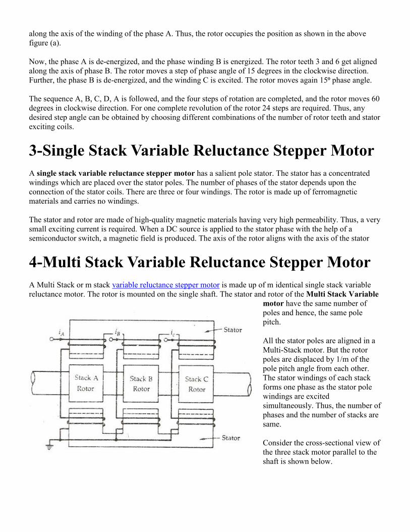
A Multi Stack or m stack variable reluctance stepper motor is made up of m identical single stack variable
reluctance motor. The rotor is mounted on the single shaft. The stator and rotor of the Multi Stack Variable
motor have the same number of
poles and hence, the same pole
pitch.
All the stator poles are aligned in a
Multi-Stack motor. But the rotor
poles are displaced by 1/m of the
pole pitch angle from each other.
The stator windings of each stack
forms one phase as the stator pole
windings are excited
simultaneously. Thus, the number of
phases and the number of stacks are
same.
Consider the cross-sectional view of
the three stack motor parallel to the
shaft is shown below.
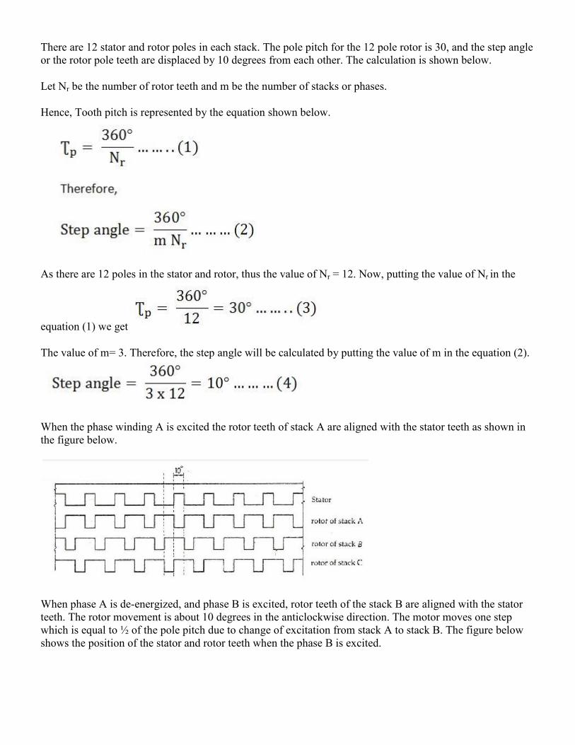
There are 12 stator and rotor poles in each stack. The pole pitch for the 12 pole rotor is 30, and the step angle
or the rotor pole teeth are displaced by 10 degrees from each other. The calculation is shown below.
Let Nr be the number of rotor teeth and m be the number of stacks or phases.
Hence, Tooth pitch is represented by the equation shown below.
As there are 12 poles in the stator and rotor, thus the value of Nr = 12. Now, putting the value of Nr in the
equation (1) we get
The value of m= 3. Therefore, the step angle will be calculated by putting the value of m in the equation (2).
When the phase winding A is excited the rotor teeth of stack A are aligned with the stator teeth as shown in
the figure below.
When phase A is de-energized, and phase B is excited, rotor teeth of the stack B are aligned with the stator
teeth. The rotor movement is about 10 degrees in the anticlockwise direction. The motor moves one step
which is equal to ½ of the pole pitch due to change of excitation from stack A to stack B. The figure below
shows the position of the stator and rotor teeth when the phase B is excited.
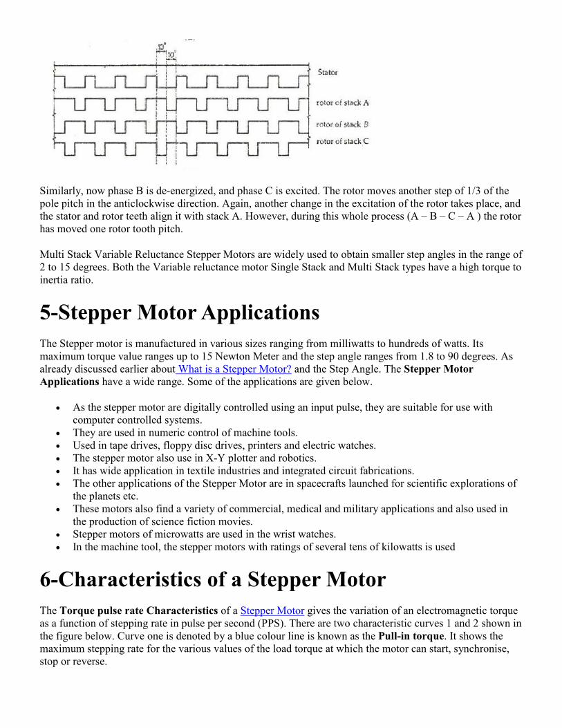
Similarly, now phase B is de-energized, and phase C is excited. The rotor moves another step of 1/3 of the
pole pitch in the anticlockwise direction. Again, another change in the excitation of the rotor takes place, and
the stator and rotor teeth align it with stack A. However, during this whole process (A – B – C – A ) the rotor
has moved one rotor tooth pitch.
Multi Stack Variable Reluctance Stepper Motors are widely used to obtain smaller step angles in the range of
2 to 15 degrees. Both the Variable reluctance motor Single Stack and Multi Stack types have a high torque to
inertia ratio.
5-Stepper Motor Applications
The Stepper motor is manufactured in various sizes ranging from milliwatts to hundreds of watts. Its
maximum torque value ranges up to 15 Newton Meter and the step angle ranges from 1.8 to 90 degrees. As
already discussed earlier about What is a Stepper Motor? and the Step Angle. The Stepper Motor
Applications have a wide range. Some of the applications are given below.
As the stepper motor are digitally controlled using an input pulse, they are suitable for use with
computer controlled systems.
They are used in numeric control of machine tools.
Used in tape drives, floppy disc drives, printers and electric watches.
The stepper motor also use in X-Y plotter and robotics.
It has wide application in textile industries and integrated circuit fabrications.
The other applications of the Stepper Motor are in spacecrafts launched for scientific explorations of
the planets etc.
These motors also find a variety of commercial, medical and military applications and also used in
the production of science fiction movies.
Stepper motors of microwatts are used in the wrist watches.
In the machine tool, the stepper motors with ratings of several tens of kilowatts is used
6-Characteristics of a Stepper Motor
The Torque pulse rate Characteristics of a Stepper Motor gives the variation of an electromagnetic torque
as a function of stepping rate in pulse per second (PPS). There are two characteristic curves 1 and 2 shown in
the figure below. Curve one is denoted by a blue colour line is known as the Pull-in torque. It shows the
maximum stepping rate for the various values of the load torque at which the motor can start, synchronise,
stop or reverse.
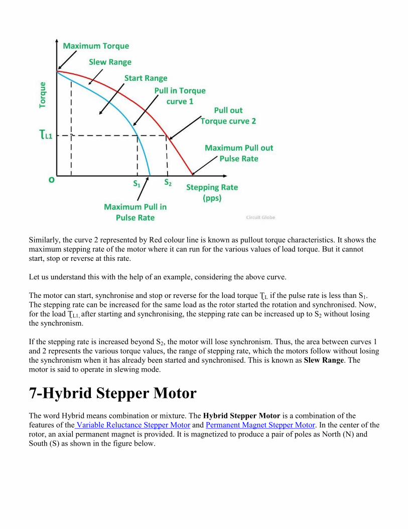
Similarly, the curve 2 represented by Red colour line is known as pullout torque characteristics. It shows the
maximum stepping rate of the motor where it can run for the various values of load torque. But it cannot
start, stop or reverse at this rate.
Let us understand this with the help of an example, considering the above curve.
The motor can start, synchronise and stop or reverse for the load torque ƮL if the pulse rate is less than S1.
The stepping rate can be increased for the same load as the rotor started the rotation and synchronised. Now,
for the load ƮL1, after starting and synchronising, the stepping rate can be increased up to S2 without losing
the synchronism.
If the stepping rate is increased beyond S2, the motor will lose synchronism. Thus, the area between curves 1
and 2 represents the various torque values, the range of stepping rate, which the motors follow without losing
the synchronism when it has already been started and synchronised. This is known as Slew Range. The
motor is said to operate in slewing mode.
7-Hybrid Stepper Motor
The word Hybrid means combination or mixture. The Hybrid Stepper Motor is a combination of the
features of the Variable Reluctance Stepper Motor and Permanent Magnet Stepper Motor. In the center of the
rotor, an axial permanent magnet is provided. It is magnetized to produce a pair of poles as North (N) and
South (S) as shown in the figure below.
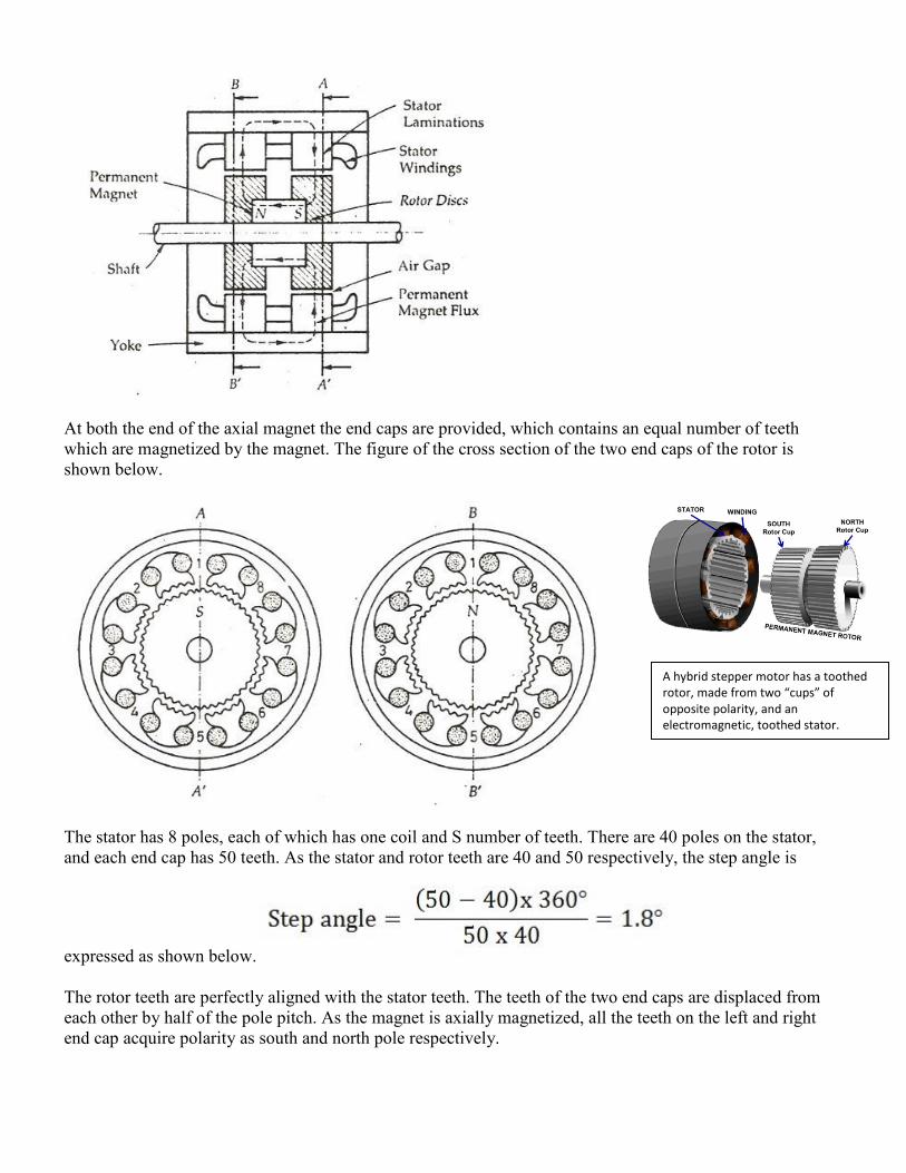
At both the end of the axial magnet the end caps are provided, which contains an equal number of teeth
which are magnetized by the magnet. The figure of the cross section of the two end caps of the rotor is
shown below.
The stator has 8 poles, each of which has one coil and S number of teeth. There are 40 poles on the stator,
and each end cap has 50 teeth. As the stator and rotor teeth are 40 and 50 respectively, the step angle is
expressed as shown below.
The rotor teeth are perfectly aligned with the stator teeth. The teeth of the two end caps are displaced from
each other by half of the pole pitch. As the magnet is axially magnetized, all the teeth on the left and right
end cap acquire polarity as south and north pole respectively.
A hybrid stepper motor has a toothed
rotor, made from two “cups” of
opposite polarity, and an
electromagnetic, toothed stator.

The coils on poles 1, 3, 5 and 7 are connected in series to form phase A. Similarly, the coils on the poles 2, 4,
6 and 8 are connected in series to form phase B.
When Phase is excited by supplying a positive current, the stator poles 1 and 5 becomes South poles and
stator pole 3 and 7 becomes north poles.
Now, when the Phase A is de-energized, and phase B is excited, the rotor will turn by a full step angle of 1.8⁰
in the anticlockwise direction. The phase A is now energized negatively; the rotor moves further by 1.8⁰ in
the same anti-clockwise direction. Further rotation of the rotor requires phase B to be excited negatively.
Thus, to produce anticlockwise motion of the rotor the phases are energized in the following sequence +A,
+B, -A, -B, +B, +A…….. For the clockwise rotation, the sequence is +A, -B, +B, +A……..
One of the main advantages of the Hybrid stepper motor is that, if the excitation of the motor is removed the
rotor continues to remain locked in the same position as before the removal of the excitation. This is because
of the Detent Torque produced by the permanent magnet.
Advantages of Hybrid Stepper Motor
The advantages of the Hybrid Stepper Motor are as follows:-
The length of the step is smaller.
It has greater torque.
Provides Detent Torque with the de-energized windings.
Higher efficiency at lower speed.
Lower stepping rate.
Disadvantages of Hybrid Stepper Motor
The Hybrid Stepper Motor has the following drawbacks.
Higher inertia.
The weight of the motor is more because of the presence of the rotor magnet.
If the magnetic strength is varied, the performance of the motor is effected.
The cost of the Hybrid motor is more as compared to the Variable Reluctance Motor.
8-Permanent Magnet Stepper Motor
The Permanent Magnet Stepper Motor has a stator construction similar to that of the single stack variable
reluctance motor. The rotor consists of permanent magnet poles of high retentivity steel and is cylindrical in
shape. The concentrating windings on diametrically opposite poles are connected in series to form a two
phase winding on the stator.
The rotor poles align with the stator teeth depending on the excitation of the winding. The two coils AA’
connected in series to form a winding of Phase A. Similarly the two coil BB’ is connected in series forming a
phase B windings.The figure below shows 4/2 Pole Permanent Magnet Stepper Motor.
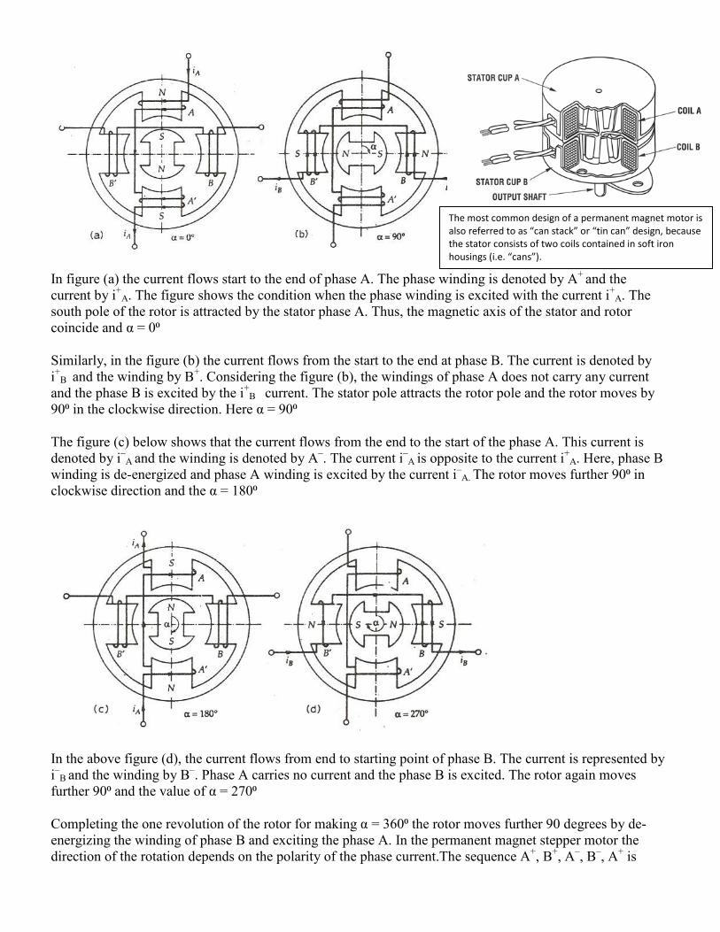
In figure (a) the current flows start to the end of phase A. The phase winding is denoted by A+
and the
current by i+
A. The figure shows the condition when the phase winding is excited with the current i+
A. The
south pole of the rotor is attracted by the stator phase A. Thus, the magnetic axis of the stator and rotor
coincide and α = 0⁰
Similarly, in the figure (b) the current flows from the start to the end at phase B. The current is denoted by
i+
B and the winding by B+. Considering the figure (b), the windings of phase A does not carry any current
and the phase B is excited by the i+
B current. The stator pole attracts the rotor pole and the rotor moves by
90⁰ in the clockwise direction. Here α = 90⁰
The figure (c) below shows that the current flows from the end to the start of the phase A. This current is
denoted by i–
A and the winding is denoted by A–. The current i
–A is opposite to the current i
+A. Here, phase B
winding is de-energized and phase A winding is excited by the current i–
A. The rotor moves further 90⁰ in
clockwise direction and the α = 180⁰
In the above figure (d), the current flows from end to starting point of phase B. The current is represented by
i–
B and the winding by B–. Phase A carries no current and the phase B is excited. The rotor again moves
further 90⁰ and the value of α = 270⁰
Completing the one revolution of the rotor for making α = 360⁰ the rotor moves further 90 degrees by de-
energizing the winding of phase B and exciting the phase A. In the permanent magnet stepper motor the
direction of the rotation depends on the polarity of the phase current.The sequence A+, B
+, A
–, B
–, A
+ is
The most common design of a permanent magnet motor is
also referred to as “can stack” or “tin can” design, because
the stator consists of two coils contained in soft iron
housings (i.e. “cans”).
followed by the clockwise movement of the rotor and for the anticlockwise movement, the sequence
becomes A+ B
–, A
–, B
+, A
+.
The permanent magnet rotor with large number of poles is difficult to make, therefore, stepper motors of this
type are restricted to large step size in the range of 30 to 90⁰. They have higher inertia and therefore, lower
acceleration than variable stepper motors. The Permanent Magnet stepper motor produces more torque than
the Variable Reluctance Stepper Motor.
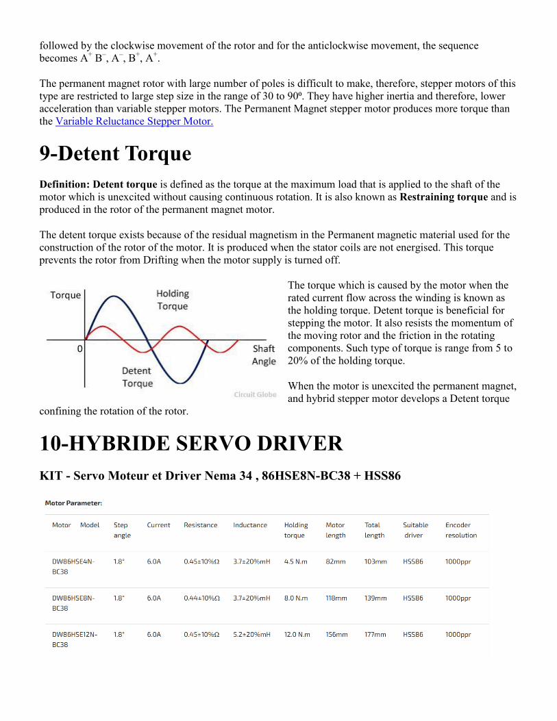
9-Detent Torque
Definition: Detent torque is defined as the torque at the maximum load that is applied to the shaft of the
motor which is unexcited without causing continuous rotation. It is also known as Restraining torque and is
produced in the rotor of the permanent magnet motor.
The detent torque exists because of the residual magnetism in the Permanent magnetic material used for the
construction of the rotor of the motor. It is produced when the stator coils are not energised. This torque
prevents the rotor from Drifting when the motor supply is turned off.
The torque which is caused by the motor when the
rated current flow across the winding is known as
the holding torque. Detent torque is beneficial for
stepping the motor. It also resists the momentum of
the moving rotor and the friction in the rotating
components. Such type of torque is range from 5 to
20% of the holding torque.
When the motor is unexcited the permanent magnet,
and hybrid stepper motor develops a Detent torque
confining the rotation of the rotor.
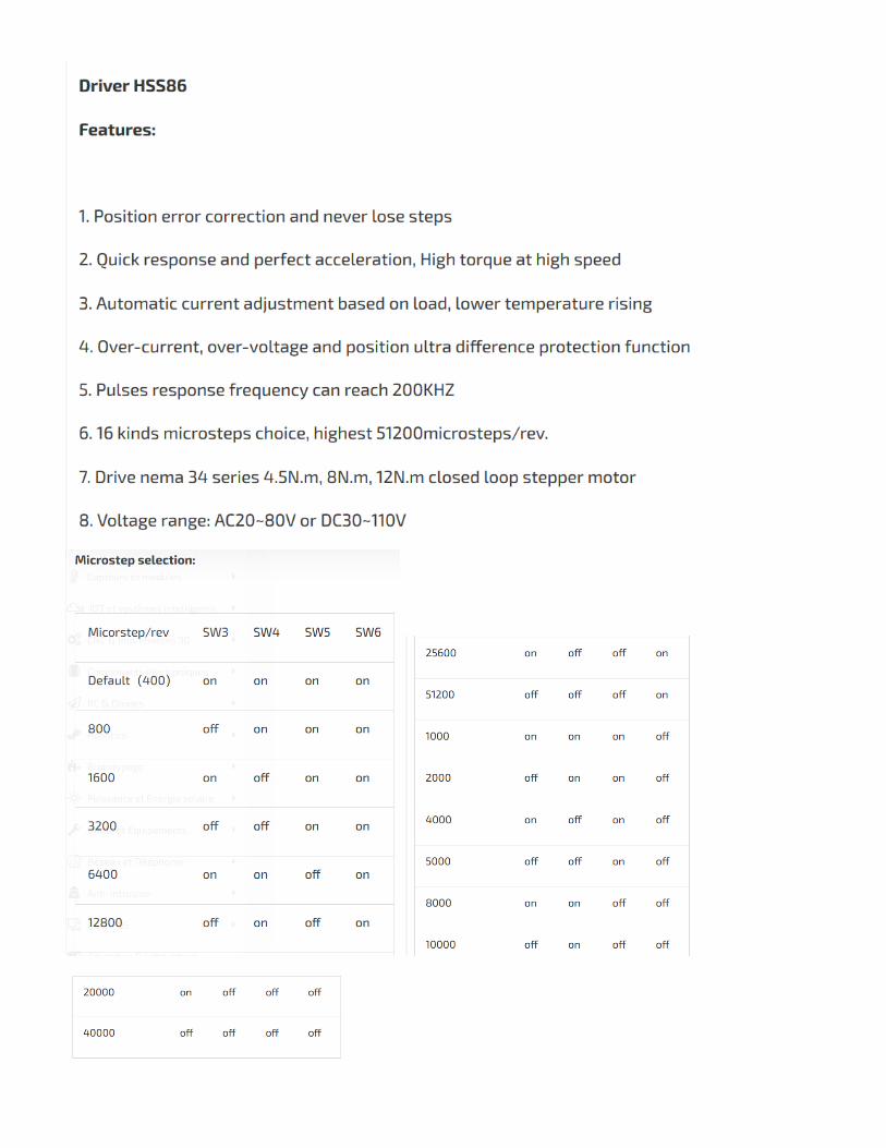
10-HYBRIDE SERVO DRIVER
KIT - Servo Moteur et Driver Nema 34 , 86HSE8N-BC38 + HSS86
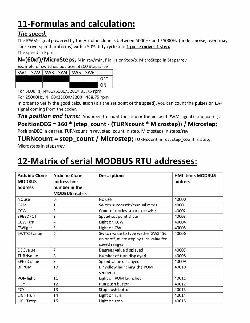
11-Formulas and calculation: The speed: The PWM signal powered by the Arduino clone is between 5000Hz and 25000Hz (under: noise, over: may
cause overspeed problems) with a 50% duty cycle and 1 pulse moves 1 step.
The speed in Rpm:
N=(60xf)/MicroSteps, N in rev/min, f in Hz or Step/s, MicroSteps in Steps/rev
Example of switches position: 3200 Steps/rev
SW1 SW2 SW3 SW4 SW5 SW6
OFF
ON
For 5000Hz, N=60x5000/3200= 93,75 rpm
For 25000Hz, N=60x25000/3200= 468,75 rpm
In order to verify the good calculation (it’s the set point of the speed), you can count the pulses on EA+
signal coming from the coder.
The position and turns: You need to count the step or the pulse of PWM signal (step_count).
PositionDEG = 360 * (step_count - (TURNcount * Microstep)) / Microstep; PositionDEG in degree, TURNcount in rev, step_count in step, Microsteps in steps/rev
TURNcount = step_count / Microstep; TURNcount in rev, step_count in step,
Microsteps in steps/rev
12-Matrix of serial MODBUS RTU addresses:
Arduino Clone
MODBUS
address
Arduino Clone
address line
number in the
MODBUS matrix
Descriptions HMI items MODBUS
address
NOuse 0 No use 40000
CAM 1 Switch automatic/manual mode 40001
CCW 2 Counter clockwise or clockwise 40002
SPEEDPOT 3 Speed set point slider 40003
CCWlight 4 Light on CCW 40004
CWlight 5 Light on CW 40005
SWITCHvalue 6 Switch value to type wether SW3456
on or off, microstep by turn value for
speed ranges
40006
DEGvalue 7 Degrees value displayed 40007
TURNvalue 8 Number of turn displayed 40008
SPEEDvalue 9 Speed value displayed 40009
BPPOM 10 BP yellow launching the POM
sequence
40010
POMlight 11 Light on POM launched 40011
DCY 12 Run push button 40012
FCY 13 Stop push button 40013
LIGHTrun 14 Light on run 40014
LIGHTstop 15 Light on stop 40015
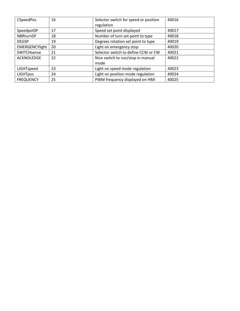
CSpeedPos 16 Selector switch for speed or position
regulation
40016
SpeedpotSP 17 Speed set point displayed 40017
NBRturnSP 18 Number of turn set point to type 40018
DEGSP 19 Degrees rotation set point to type 40019
EMERGENCYlight 20 Light on emergency stop 40020
SWITCHsense 21 Selector switch to define CCW or CW 40021
ACKNOLEDGE 22 Nice switch to run/stop in manual
mode
40022
LIGHTspeed 23 Light on speed mode regulation 40023
LIGHTpos 24 Light on position mode regulation 40024
FREQUENCY 25 PWM frequency displayed on HMI 40025