Embed Size (px)
Citation preview
Some Thoughts on View Camera Calculations
Leonard EvensDepartment of Mathematics
Northwestern [email protected]
February 9, 2003
The purpose of this article is to explore how simple geometric optics may help a largeformat photographer. It is aimed at readers who are comfortable with formulas and simplealgebra and are familiar with the basics of how to use a view camera, but it doesn’t requireanything beyond that. I wrote it to clarify the basic principles in my own mind, and I hopeit may be useful for some others. I explore how certain simple formulas can enhance one’stechnique, but of course one must always keep in mind the primacy of the image on theground glass and what it says. This is also a work in progress, and it may very well containmistakes or misconceptions. If you find anything like that, please report it to me. I wasinspired in part by Bob Wheeler’s notes, and the reader who wants to learn more shouldlook there. (www.bobwheeler.com/photo). Very little of this is original with me, and thatpart may be wrong, but I’ve found that some of it doesn’t seem universally known.
1 Measuring along the rail
I used a Horseman Technical Camera (6 x 7 format) for many years before finally getting aToho 4 x 5 view camera in 2002. The Horseman has limited front and back movements, so Ihad mastered the basics of view camera technique. But I found there were some significantdifferences between what worked for the Horseman and what I now do. As a professionalmathematician, I am fascinated by optical formulas. But, even for me, formulas have to bevery simple to be useful in the field. One of my aims was to derive a set of methods whichcould be applied using mental arithmetic, or at worst the simplest possible calculator. Thatis not always possible, but it is surprising how often it is.
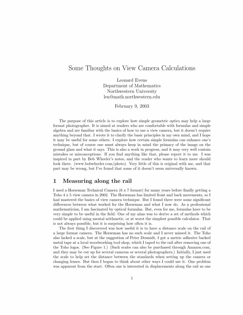
The first thing I discovered was how useful it is to have a distance scale on the rail ofa large format camera. The Horseman has no such scale and I never missed it. The Tohoalso lacked a scale, but at the suggestion of Peter Desmidt, I got a metric adhesive backedmetal tape at a local woodworking tool shop, which I taped to the rail after removing one ofthe Toho logos. (See Figure 1.) (Such scales can also be purchased through Amazon.com,and they may be cut up for several cameras or several photographers.) Initially, I just usedthe scale to help set the distance between the standards when setting up the camera orchanging lenses. But then I began to think about other ways I could use it. One problemwas apparent from the start. Often one is interested in displacements along the rail as one
1
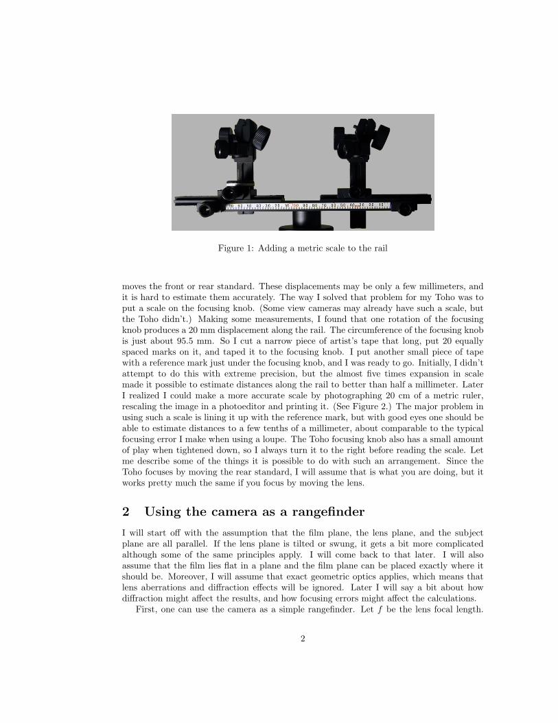
Figure 1: Adding a metric scale to the rail
moves the front or rear standard. These displacements may be only a few millimeters, andit is hard to estimate them accurately. The way I solved that problem for my Toho was toput a scale on the focusing knob. (Some view cameras may already have such a scale, butthe Toho didn’t.) Making some measurements, I found that one rotation of the focusingknob produces a 20 mm displacement along the rail. The circumference of the focusing knobis just about 95.5 mm. So I cut a narrow piece of artist’s tape that long, put 20 equallyspaced marks on it, and taped it to the focusing knob. I put another small piece of tapewith a reference mark just under the focusing knob, and I was ready to go. Initially, I didn’tattempt to do this with extreme precision, but the almost five times expansion in scalemade it possible to estimate distances along the rail to better than half a millimeter. LaterI realized I could make a more accurate scale by photographing 20 cm of a metric ruler,rescaling the image in a photoeditor and printing it. (See Figure 2.) The major problem inusing such a scale is lining it up with the reference mark, but with good eyes one should beable to estimate distances to a few tenths of a millimeter, about comparable to the typicalfocusing error I make when using a loupe. The Toho focusing knob also has a small amountof play when tightened down, so I always turn it to the right before reading the scale. Letme describe some of the things it is possible to do with such an arrangement. Since theToho focuses by moving the rear standard, I will assume that is what you are doing, but itworks pretty much the same if you focus by moving the lens.
2 Using the camera as a rangefinder
I will start off with the assumption that the film plane, the lens plane, and the subjectplane are all parallel. If the lens plane is tilted or swung, it gets a bit more complicatedalthough some of the same principles apply. I will come back to that later. I will alsoassume that the film lies flat in a plane and the film plane can be placed exactly where itshould be. Moreover, I will assume that exact geometric optics applies, which means thatlens aberrations and diffraction effects will be ignored. Later I will say a bit about howdiffraction might affect the results, and how focusing errors might affect the calculations.
First, one can use the camera as a simple rangefinder. Let f be the lens focal length.
2
Figure 2: Scale on the focusing knob
Assume you are focused on a subject plane at a certain distance u from the lens plane.Let d be the extension beyond f , i.e., beyond the position when the lens is focused atinfinity. Then for sufficiently distant objects, the distance to the subject plane is givenquite accurately by
u =f2
d.
For example, suppose one is using a 90 mm lens, and the extension beyond infinity focus is
2 mm. Then, the subject plane must be just about at8100
2= 4050 mm = 4.05 meters.
If one is doing closeup work, then the exact formula is
u =f(f + d)
d,
which is slightly harder to compute with.Cameras and lenses for 35 mm and medium format cameras usually have distance scales
which tell you how far the subject plane is. One could improvise such scales for a viewcamera, one for each lens, so the subject distance could be read directly without calculatinganything. But it has become increasingly apparent to me that the distance to the subjectplane is often not relevant. All the information you need is available through measurementsmade on the camera directly. So the linear distance scale on the rail, as expanded on thefocusing knob, is all you really need.
3

3 Hyperfocal technique
Let me illustrate that principle by discussing the hyperfocal distance. As most photogra-phers know, if you focus at the hyperfocal distance, then everything from half that distanceto infinity will, in principle, be in focus. What does the hyperfocal distance correspond toas a displacement along the rail? That requires a little algebra. The usual formula for thehyperfocal distance is
h =f2
Nc
where f , as above, is the focal length, N is the f-number, and c is the diameter of thelargest allowable circle of confusion in the film plane. The circle of confusion bounds adisc in the film plane which results when the exact image point is a slight distance fromthe film plane. If that disc is small enough, after enlargement in a final print, it won’t bedistinguishable from a point. The proper value of c depends on the format, and there isconsiderable difference of opinion about what it should be for any given format. For 4 x5 photography, the acceptable range seems to be 0.05 mm to 0.125 mm. In this article Iwill generally use c = 0.1 mm, but there is nothing magic about that, and you may preferanother value. (See 3.1.)
Assume now that you are focused at the hyperfocal distance so that u = h. Comparethe two formulas
h =f2
dand h =
f2
Nc.
Since the numerators are the same, the denominators must also be the same, i.e.,
d = Nc. (1)
In other words, to focus at the hyperfocal distance, set the rear standard N times c unitsbeyond the position for focusing at infinity.
What about half the hyperfocal distance? In that case, u = h2 . If the extension along
the rail beyond infinity for the half the hyperfocal distance is d′, we have
h
2=
f2
d′
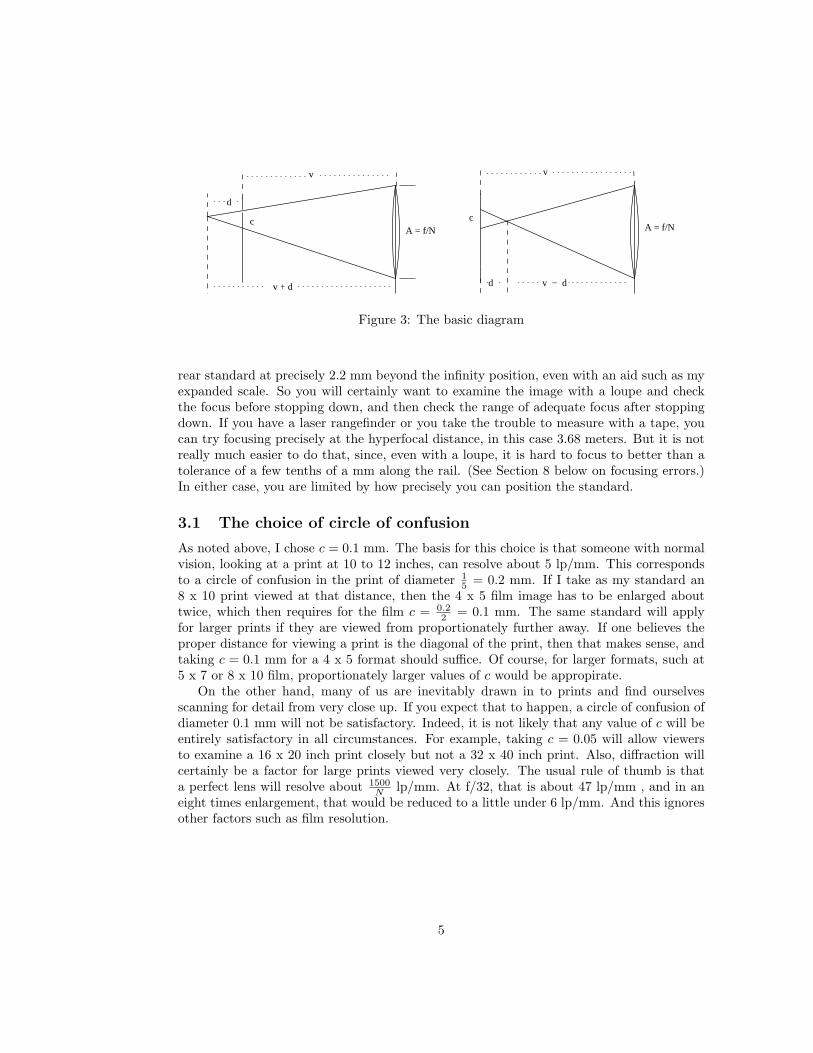
so it follows by some simple algebra, that d′ = 2d = 2Nc. See Figure 3 for a picture ofthis. You see that when the rear standard is displaced d = Nc units from the infinity focusposition, i.e., the lens to film distance is v = f +d, then any image point which lies within dunits of either side of the film plane will produce a sufficiently small blur in the film plane.
Note that you can now forget about the hyperfocal distance. The distance d = Nc isindependent of focal length, and it is really the only number you need to know in orderto apply hyperfocal technique. Of course, if you want, you can double check by the usualmethods, provided you have some method to measure the distance to the subject planeprecisely. Let’s look at an example. Suppose, like me, you take c = 0.1, and you stop downto f/22. Then you should set the rear standard 22 (0.1) = 2.2 mm beyond the infinity settingto be focused on the hyperfocal distance for any focal length lens. For a 90 mm lens, that
corresponds to a subject plane at81002.2
= 3.68 meters. Of course, it is hard to position the
4
d
c
v + d
v v
v − dd
cA = f/NA = f/N
Figure 3: The basic diagram
rear standard at precisely 2.2 mm beyond the infinity position, even with an aid such as myexpanded scale. So you will certainly want to examine the image with a loupe and checkthe focus before stopping down, and then check the range of adequate focus after stoppingdown. If you have a laser rangefinder or you take the trouble to measure with a tape, youcan try focusing precisely at the hyperfocal distance, in this case 3.68 meters. But it is notreally much easier to do that, since, even with a loupe, it is hard to focus to better than atolerance of a few tenths of a mm along the rail. (See Section 8 below on focusing errors.)In either case, you are limited by how precisely you can position the standard.
3.1 The choice of circle of confusion
As noted above, I chose c = 0.1 mm. The basis for this choice is that someone with normalvision, looking at a print at 10 to 12 inches, can resolve about 5 lp/mm. This correspondsto a circle of confusion in the print of diameter 1
5 = 0.2 mm. If I take as my standard an8 x 10 print viewed at that distance, then the 4 x 5 film image has to be enlarged abouttwice, which then requires for the film c = 0.2
2 = 0.1 mm. The same standard will applyfor larger prints if they are viewed from proportionately further away. If one believes theproper distance for viewing a print is the diagonal of the print, then that makes sense, andtaking c = 0.1 mm for a 4 x 5 format should suffice. Of course, for larger formats, such at5 x 7 or 8 x 10 film, proportionately larger values of c would be appropirate.
On the other hand, many of us are inevitably drawn in to prints and find ourselvesscanning for detail from very close up. If you expect that to happen, a circle of confusion ofdiameter 0.1 mm will not be satisfactory. Indeed, it is not likely that any value of c will beentirely satisfactory in all circumstances. For example, taking c = 0.05 will allow viewersto examine a 16 x 20 inch print closely but not a 32 x 40 inch print. Also, diffraction willcertainly be a factor for large prints viewed very closely. The usual rule of thumb is thata perfect lens will resolve about 1500
N lp/mm. At f/32, that is about 47 lp/mm , and in aneight times enlargement, that would be reduced to a little under 6 lp/mm. And this ignoresother factors such as film resolution.
5
4 Getting what you want to be sharp in focus
The amazing thing is that the same principle mostly works at any distance, not only atthe hyperfocal distance. (But see below for exact formulas and how in certain cases, suchas closeups, one must modify the method.) In more detail, suppose the rear standard ispositioned for exact focus on some subject plane at another distance v from the lens. Then,any image point which is within the distance d = Nc on either side of the film plane willproject a disc in the film plane which is not distinguishable from a point. That means thecorresponding subject point will be within the acceptable depth of field. If you want, youcan calculate the depth of field, but it is not necessary to do so.
That leads to an old method for focusing a view camera. Focus on the furthest point youwant to be in focus, then on the nearest point, and note the two positions on the scale. Then,place the standard halfway in between. This has just exactly the desired effect; namely thedistance of the film plane from either position is the same distance and the film plane issymmetrically placed between. As above, that distance is d = Nc.
It goes without saying that you can’t follow this rule blindly. Your estimate of thepositions of the near and far focus points be will be off slightly due to focusing error. Youcan decrease this by using a loupe, but you can’t eliminate it. (See Section 8 on focusingerrors for further discussion of this issue and possible ways to minimize it.) If the distancebetween the near and far focus points is small, the focusing error will eat up a considerablepart of the range. Also, other factors may affect where you want to focus. So you certainlyhave to check this by what you see on the ground glass.
We can use these facts to determine what the f-stop should be to keep everything infocus, at least for relatively large apertures where diffraction is not much of a problem. Letw be the distance along the scale between the positions for near and far focus, or what isusually called the focus spread. As just noted, d = Nc =
w
2, so
N =w
2c.
Let’s try an example. Suppose you find that the focus spread is w = 3 mm, and as above
you use c = 0.1. Then N should be3
2(0.1)= 15. Thus if you stop down to f/16, that should
suffice. Again, in practice you would check this on the ground glass at the taking apertureand perhaps make some adjustments. The calculation is based on the assumptions thatyou have a perfect lens obeying the strict laws of geometric optics, and that you can focusperfectly at the near and far focus points. Real lenses have aberrations and there is alwayssome focusing error, so you may want to stop down one or two additional stops to be sure,to the extent that subject motion and diffraction effects allow.
The arithmetic is not so easy if you don’t choose a simple value of c like 0.1mm. In thatcase, it is easy enough to prepare a table which for different values of the focus spread tellsyou the f-number to use.
If the focus spread is large, i.e., you are aiming for a lot of depth of field, then, as theformula indicates, you will have to stop down considerably. If so, diffraction will become asignificant factor, and you may want to use another approach. (See below.) In addition, itmay be difficult to judge visually what is in focus because the image will be so dim. Usinga loupe can help, but it should be remembered that doing so may decrease the apparent
6
depth of field because with high magnification, you are in effect choosing a very small circleof confusion, perhaps smaller than you intended. For example, looking at at a 4 x 5 imagewith a 4 X loupe corresponds roughly to viewing a 16 x 20 inch print from about 10 to 12inches, and looking at it with an 8 X loupe corresponding to viewing a 32 x 40 inch printat that distance.
It should also be noted that some people don’t believe that dividing the focus spreadequally produces the best results. There seems to a lot of debate about it, and reasonablearguments can be made for other ways to do it. For example, it might be argued thatyou should be more critical about sharpness for small distant objects than for large nearbyobjects. That means you should want a smaller circle of confusion for image points closer tothe lens than for image points further from the lens. That of course changes the mathematics.If you want the largest circle of confusion for distant points to be half that for near points,then the proper subdivision of the focus spread changes. The focus should be set at
w
3from
the distant focus point and2w
3from the near focus point. (See Joe Englander.) Others
would see this as an unacceptable waste of some of the usable depth of field. (However,there is a plausible argument for always favoring the distant focus slightly, particularly forextreme wide angle lenses. See Section 7.)
How does all this apply to close up objects? If the focus spread between the near and farfocus is not too large, then all you need to do is to replace the f-number N by the effectivef-number
Ne = N(1 + M)
where M is the scale of reproduction. This is the same quantity that is used to makeexposure adjustments for closeups. You can still use the formula
d = Nec
as above, and nothing else changes. The actual f-number is given by
N =Ne
1 + M=
w
2c
11 + M
.
If you ignore this factor 1 + M , you overestimate the needed f-number, which in manysituations is innocuous.
It should be noted that you can determine the factor 1 + M from measurements alongthe rail. Namely, if d∞ is the extension of the lens from infinity when focused on the subject,then
1 + M = 1 +d∞f
.
You may also estimate M by putting a circular disk of known diameter at the plane ofprincipal focus and measuring its longest dimension on the ground glass.
(See www.salzgeber.at/disc for an application of this principle for estimating exposurecorrection.)
However, when working with extreme wide angle lenses and small apertures, the focusspread w may be a large fraction of the focal length, particularly for closeups. In that casethe approximate formulas I’ve been using are no longer accurate enough, and you have touse exact formulas instead. The analysis is more complex, and not so easy to apply withsimple arithmetic. I discuss this in Section 7.
7
4.1 Brief remarks on diffraction
In our discussion so far, we have ignored diffraction. Even a perfect lens is limited bydiffraction and if you stop down enough, the image of a point—the so called Airy disc—maybe comparable in size to whatever circle of confusion you set for yourself. The smaller youset the circle of confusion, the sooner that will happen. The overall effect of diffraction isto degrade resolution throughout the image, so its effect on the perception of what is sharpin the image can be complicated. It appears that large format photographers differ in howthey approach diffraction and how seriously they take it. Many feel that you should not letthe specter of diffraction dissuade from using very small apertures if you need them to getadequate depth of field.
In our discussions, we have specified a largest acceptable circle of confusion and used theformula Ne = w
2c to determine the f-number. This method may be modified to account fordiffraction in a variety of ways. A complete analysis requires the use of modulation transferfunctions which give the complete spatial frequency response for each factor. But there aretwo simple rules of thumb which are often used instead to estimate the combined effect.You can just add the diameters of the discs or you can take the square root of the sum ofthe squares. Using either one, you pick N so the combined effect is not greater than youracceptable error. See the link to Peterson at www.largeformatphotography.info/fstop.htmlfor a discussion of how to do that based on the second rule.
That web site also discusses an alternate approach, based on an article of Paul Hansma.Instead of fixing a maximal allowable error disc, the f-stop is chosen so that the combinedeffect of diffraction and geometric defocus at the limits of the depth of field is as small aspossible. It turns out that either rule of thumb for combining errors yields the same formulafor the optimal f-number
Ne =√
375w
where, as above, w is the focus spread. For small focus spreads, this will tend to give alarger f-number than may be necessary. The aperture will be relatively large in such cases,and diffraction is neglible for typical degrees of enlargement. So the formula Ne = w
2c givesa reasonable estimate, particularly if you stop down an additional stop. (Of course, it won’thurt to stop down more, if you can, since that will allow making very large prints which canbe viewed very closely.) On the other hand this method may give a more realistic f-numberfor a large focus spread, since at smaller apertures diffraction plays a more prominent role.
Wheeler, using half the estimate for the contribution from the Airy disc, comes up insteadwith
Ne =√
750w.
Wheeler bases his estimate on the Rayleigh criterion for when two points will be resolved,while Hansma uses the diameter of the Airy disc.
Both Hansma and Wheeler cite observational verification for their estimates. I don’tclaim to understand the matter very well, but it seems to me that any simple scheme forcombining the Airy disc with the circle of confusion from defocus is questionable. But theseanalyses do show that for large focus spreads which would entail relatively small apertures,diffraction will limit resolution enough that very large prints viewed very close up are boundto show some fuzziness.
8
Note that, as before, the formulas give the necessary effective f-number, and the actualf-number would be obtained by dividing that by 1 + M .
4.2 Setting the f-stop precisely
F-stops on lenses are usually marked in ’fractions’ of an f-stop. The relation between theratio of f-number N to N0 and the corresponding fraction of an f-stop is
ν =2 log(N/N0)
log 2.
It doesn’t matter which base logarithm you use. For example, if the f-number is 40, thatcorresponds to 2 log(40/45)
log 2 = −.34 f-stops. In other words, it is just about one third stopless than f/45.
For convenience, here is a table of f-numbers and the corresponding displacement, up ordown, from the nearest marked f-stop.
f-number stop5 5.6-.3310 11-.2815 16-.1920 20-.2825 22+.3730 32-.1935 32+.2640 45-.3445 45+.0050 45+.3055 64-.4460 64-.09
Note that the the two numbers in the right column are in different scales. The first islinear, while the second is logarithmic. Some digital exposure meters will show the f-number35 as 32.26, but it seems to me this is bound to be confusing if the user doesn’t understandjust what the numbers mean.
Here is a table giving Hansma’s estimates for f-number and f-stop for different focusspreads.
9
w f-number stop1 19.4 22-.361.5 23.7 22+.222 27.4 32-.223 33.5 32+.144 38.7 45-.455 43.3 45-.116 47.4 45+.157 51.2 45+.388 54.8 64-.439 58.0 64-.2610 61.2 64-.1311 64.2 64+.00
5 Tilted lens plane
When the lens plane is parallel to the film plane, the plane of principal focus is parallel toboth of them, and you have to rely on depth of field to get everything you want in focus. Bychanging the angle that the lens plane makes with the film plane you can alter the positionof the subject plane so as to improve sharpness for important parts of the subject. Thismay be done by tilting or/and swinging either the lens or the back, but for convenience Iwill assume the lens is being tilted. The Scheimpflug rule tells us that the film plane, thelens plane, and the plane of exact focus in the subject all intersect in a line. Visualizing thelocation of that line is the first step, but determining the tilt angle can be tricky.
There are broadly two extreme cases that one encounters, and I will consider them apart,although in practice it may sometimes be hard to separate them.
5.1 Primary subjects in a plane
It often happens that the primary subjects of interest lie very close to a single plane. Inthis case, if we get the tilt angle right, then we need not stop down very far in order to geteverything we want in focus.
Wheeler has derived a simple method for determining how far to tilt the lens if you knowwhere you want to place subject plane. I’ve known this method for a while, but I neverused it, because making the measurements with my Horseman was not easy. But I recentlytried it with my modified Toho, and I was surprised how well it works.
It has several forms, but the one I find most useful is the following. It works if substan-tially all the subject points are distant from the lens. With the lens plane and film planeparallel, find two points, near and far, which you want to be in focus in the desired subjectplane. Find the distance between them along the rail; call that W . Next find the verticaldistance on the ground glass between those points, call it H. (The transparent six inchmetric ruler I found at Office Depot comes in handy for that.) Let R be the pivot radius,i.e., the distance from top of the front standard to the axis it pivots on, wherever that is.Then according to Wheeler, you should move the top of the front standard x units forward
10
wherex =
W
HR.
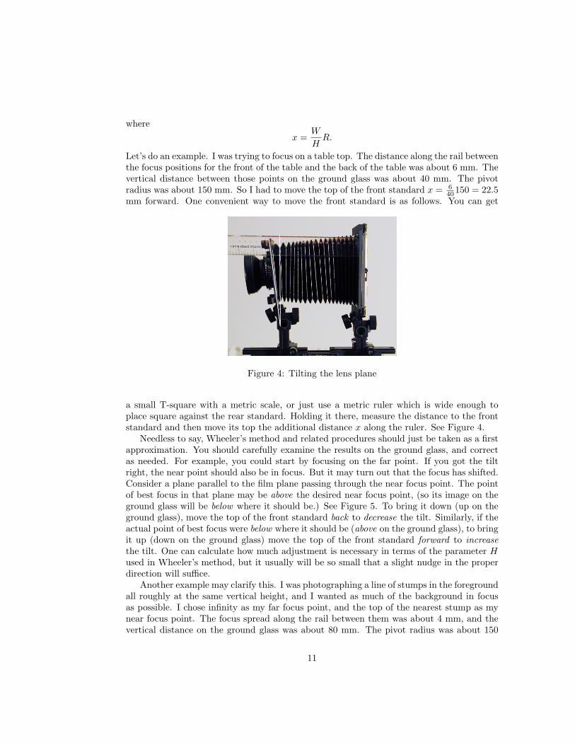
Let’s do an example. I was trying to focus on a table top. The distance along the rail betweenthe focus positions for the front of the table and the back of the table was about 6 mm. Thevertical distance between those points on the ground glass was about 40 mm. The pivotradius was about 150 mm. So I had to move the top of the front standard x = 6
40150 = 22.5mm forward. One convenient way to move the front standard is as follows. You can get
Figure 4: Tilting the lens plane
a small T-square with a metric scale, or just use a metric ruler which is wide enough toplace square against the rear standard. Holding it there, measure the distance to the frontstandard and then move its top the additional distance x along the ruler. See Figure 4.
Needless to say, Wheeler’s method and related procedures should just be taken as a firstapproximation. You should carefully examine the results on the ground glass, and correctas needed. For example, you could start by focusing on the far point. If you got the tiltright, the near point should also be in focus. But it may turn out that the focus has shifted.Consider a plane parallel to the film plane passing through the near focus point. The pointof best focus in that plane may be above the desired near focus point, (so its image on theground glass will be below where it should be.) See Figure 5. To bring it down (up on theground glass), move the top of the front standard back to decrease the tilt. Similarly, if theactual point of best focus were below where it should be (above on the ground glass), to bringit up (down on the ground glass) move the top of the front standard forward to increasethe tilt. One can calculate how much adjustment is necessary in terms of the parameter Hused in Wheeler’s method, but it usually will be so small that a slight nudge in the properdirection will suffice.
Another example may clarify this. I was photographing a line of stumps in the foregroundall roughly at the same vertical height, and I wanted as much of the background in focusas possible. I chose infinity as my far focus point, and the top of the nearest stump as mynear focus point. The focus spread along the rail between them was about 4 mm, and thevertical distance on the ground glass was about 80 mm. The pivot radius was about 150
11
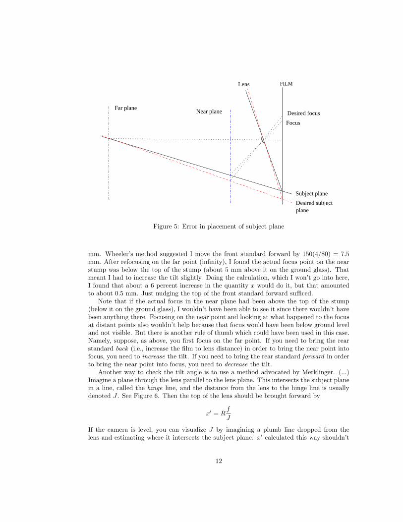
FILMLens
Far planeNear plane
Subject plane
Desired subjectplane
Focus
Desired focus
Figure 5: Error in placement of subject plane
mm. Wheeler’s method suggested I move the front standard forward by 150(4/80) = 7.5mm. After refocusing on the far point (infinity), I found the actual focus point on the nearstump was below the top of the stump (about 5 mm above it on the ground glass). Thatmeant I had to increase the tilt slightly. Doing the calculation, which I won’t go into here,I found that about a 6 percent increase in the quantity x would do it, but that amountedto about 0.5 mm. Just nudging the top of the front standard forward sufficed.
Note that if the actual focus in the near plane had been above the top of the stump(below it on the ground glass), I wouldn’t have been able to see it since there wouldn’t havebeen anything there. Focusing on the near point and looking at what happened to the focusat distant points also wouldn’t help because that focus would have been below ground leveland not visible. But there is another rule of thumb which could have been used in this case.Namely, suppose, as above, you first focus on the far point. If you need to bring the rearstandard back (i.e., increase the film to lens distance) in order to bring the near point intofocus, you need to increase the tilt. If you need to bring the rear standard forward in orderto bring the near point into focus, you need to decrease the tilt.
Another way to check the tilt angle is to use a method advocated by Merklinger. (...)Imagine a plane through the lens parallel to the lens plane. This intersects the subject planein a line, called the hinge line, and the distance from the lens to the hinge line is usuallydenoted J . See Figure 6. Then the top of the lens should be brought forward by
x′ = Rf
J
If the camera is level, you can visualize J by imagining a plumb line dropped from thelens and estimating where it intersects the subject plane. x′ calculated this way shouldn’t
12
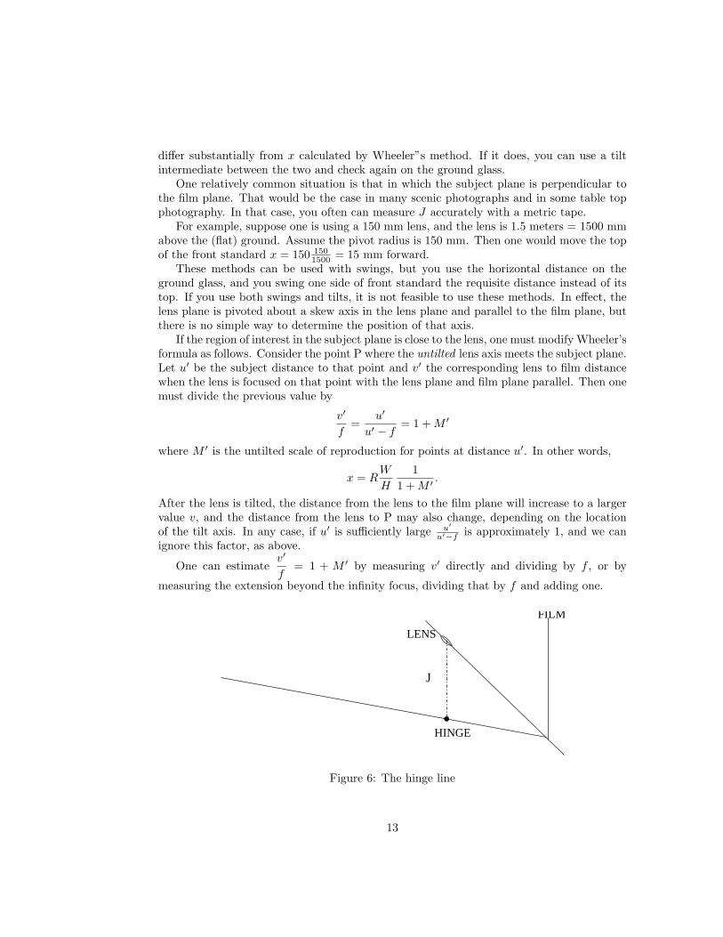
differ substantially from x calculated by Wheeler”s method. If it does, you can use a tiltintermediate between the two and check again on the ground glass.
One relatively common situation is that in which the subject plane is perpendicular tothe film plane. That would be the case in many scenic photographs and in some table topphotography. In that case, you often can measure J accurately with a metric tape.
For example, suppose one is using a 150 mm lens, and the lens is 1.5 meters = 1500 mmabove the (flat) ground. Assume the pivot radius is 150 mm. Then one would move the topof the front standard x = 150 150
1500 = 15 mm forward.These methods can be used with swings, but you use the horizontal distance on the
ground glass, and you swing one side of front standard the requisite distance instead of itstop. If you use both swings and tilts, it is not feasible to use these methods. In effect, thelens plane is pivoted about a skew axis in the lens plane and parallel to the film plane, butthere is no simple way to determine the position of that axis.
If the region of interest in the subject plane is close to the lens, one must modify Wheeler’sformula as follows. Consider the point P where the untilted lens axis meets the subject plane.Let u′ be the subject distance to that point and v′ the corresponding lens to film distancewhen the lens is focused on that point with the lens plane and film plane parallel. Then onemust divide the previous value by
v′
f=
u′
u′ − f= 1 + M ′
where M ′ is the untilted scale of reproduction for points at distance u′. In other words,
x = RW
H
11 + M ′ .
After the lens is tilted, the distance from the lens to the film plane will increase to a largervalue v, and the distance from the lens to P may also change, depending on the locationof the tilt axis. In any case, if u′ is sufficiently large u′
u′−f is approximately 1, and we canignore this factor, as above.
One can estimatev′
f= 1 + M ′ by measuring v′ directly and dividing by f , or by
measuring the extension beyond the infinity focus, dividing that by f and adding one.
HINGE
LENS
FILM
J
Figure 6: The hinge line
13
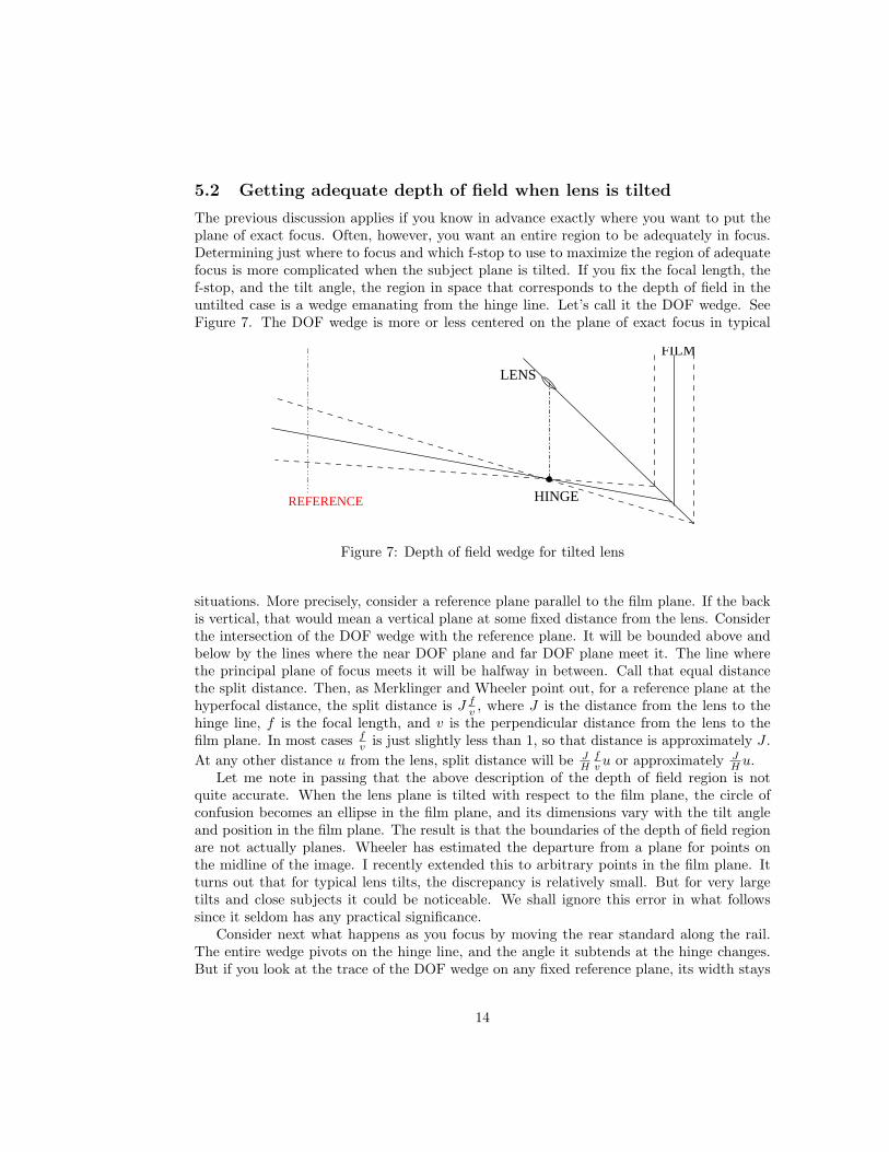
5.2 Getting adequate depth of field when lens is tilted
The previous discussion applies if you know in advance exactly where you want to put theplane of exact focus. Often, however, you want an entire region to be adequately in focus.Determining just where to focus and which f-stop to use to maximize the region of adequatefocus is more complicated when the subject plane is tilted. If you fix the focal length, thef-stop, and the tilt angle, the region in space that corresponds to the depth of field in theuntilted case is a wedge emanating from the hinge line. Let’s call it the DOF wedge. SeeFigure 7. The DOF wedge is more or less centered on the plane of exact focus in typical
HINGE
LENS
FILM
REFERENCE
Figure 7: Depth of field wedge for tilted lens
situations. More precisely, consider a reference plane parallel to the film plane. If the backis vertical, that would mean a vertical plane at some fixed distance from the lens. Considerthe intersection of the DOF wedge with the reference plane. It will be bounded above andbelow by the lines where the near DOF plane and far DOF plane meet it. The line wherethe principal plane of focus meets it will be halfway in between. Call that equal distancethe split distance. Then, as Merklinger and Wheeler point out, for a reference plane at thehyperfocal distance, the split distance is J f
v , where J is the distance from the lens to thehinge line, f is the focal length, and v is the perpendicular distance from the lens to thefilm plane. In most cases f
v is just slightly less than 1, so that distance is approximately J .At any other distance u from the lens, split distance will be J
Hfv u or approximately J
H u.Let me note in passing that the above description of the depth of field region is not
quite accurate. When the lens plane is tilted with respect to the film plane, the circle ofconfusion becomes an ellipse in the film plane, and its dimensions vary with the tilt angleand position in the film plane. The result is that the boundaries of the depth of field regionare not actually planes. Wheeler has estimated the departure from a plane for points onthe midline of the image. I recently extended this to arbitrary points in the film plane. Itturns out that for typical lens tilts, the discrepancy is relatively small. But for very largetilts and close subjects it could be noticeable. We shall ignore this error in what followssince it seldom has any practical significance.
Consider next what happens as you focus by moving the rear standard along the rail.The entire wedge pivots on the hinge line, and the angle it subtends at the hinge changes.But if you look at the trace of the DOF wedge on any fixed reference plane, its width stays
14
the same with the exact focus splitting it in two.So how should you use these facts in practice when you want to get as much as possible
in focus? First, you should not expect miracles. Always see if you can obtain what youwant with the lens plane parallel to the film plane just using depth of field at an appropriatef-stop. If that doesn’t work, it will be because you have something in the foreground whichyou can’t keep in focus without sacrificing the background, which usually means some partof the subject is well short of the hyperfocal distance. By tilting the lens, you will be ableto do a better job of keeping parts of the foreground and background in focus, but you willpay a price in depth of field transverse to the exact plane of focus at any given f-stop. Thismay be particularly limiting for elements of the subject in the foreground.
So consider a typical problem in landscape photography, some flowers fairly close to thelens and something such as trees or hills with vertical extent in the background. To bedefinite, let’s suppose you have a hill at some distance from the lens. If the flowers also havevertical significant extent, tilting the lens is not going to do much good, so suppose that isnot the case.
Let me describe two methods you might use.First method
Keeping in mind the vertical split of the wedge, pick a point on the hill about half wayup as your distant point and a point in the foreground as your near point. Use those todetermine your tilt, and note the position of the rear standard on the rail. Next move therear standard back and forth and note the locations on the rail where the plane of exactfocus passes through the top and bottom of the hill. Make sure those planes encompass allthe interesting detail at other distances also. In particular, if you have a problem in theforeground, that suggests you didn’t get the tilt angle right, so try adjusting it slightly asindicated in 5.1.
You now have determined a focus spread on the rail just as previously. The positionof best focus should be approximately in the middle. (It should actually be slightly closerto the lens than that, but in common situations not enough to bother. See Section 7.) Itshould also be quite close to where you set it when fixing the tilt. If you could focus exactly,there would be no error, but that is never possible in the real world, so you should toleratea small error. If it is larger, you may want to again try adjusting the tilt slightly to improvethings.Second method
Pick as your far point the highest point on the hill and a near point as before. Use theseto determine the tilt angle. (It should be less than that produced by the first method.)Note the position on the rail. Move the rear standard so the lowest desired point on thehill comes into focus and note that position on the rail. Use these two points to establishthe focus spread instead, and move the standard to its center to establish the plane of exactfocus.
The second method may have the advantage of yielding a smaller focus spread and henceit may allow for a larger aperture. To see why, look at the expression for the split distanceat distance u from the lens. It is
J
H
f
vu = · · · = Nc/f
sin(φ)v/fu.
where the dots represent some algebra that I omit. On the other hand, if the tilt angle is
15
not too large and the subject plane not too steeply inclined with respect to the horizontal, itturns out that v/f is pretty close to one. That means that as you decrease φ (hence sin(φ)),if you compensate by decreasing N , you can keep the split distance at any given distancefrom the lens more or less fixed. Indeed you can match any change in the amount you movethe top of the front standard forward by a proportional change in the f-number.
One problem with the second method, however, is that you are relying on the calculationsto work to be sure important parts of the foreground remain in focus. With the first method,you can see that they are in focus with the lens wide open.
Having established the tilt one way or another, you want to determine which f-stop touse to make sure the wedge is broad enough to encompass everything of interest. You canuse essentially the same formulas as before to do that in terms of the focus spread. But thebasic formula for the rail distance on either side of the midpoint focus position becomes
d = (Nc) Q with Q =v
f,
where v is the distance from the lens to the film plane and f is the focal length. To see howthis is related to the previous formula, note that
Q =v
f=
1 + M
cos(φ)
where φ is the tilt angle, and M is the scale of reproduction, after tilting, for the point Pwhere the untilted lens axis intersects the subject plane.
Let w be the focus determined as above. Then, the formula for N becomes
N =w
2c
1Q
.
For typical scenes, Q is not much larger than 1, and, in any event, if you ignore it, all youdo is overestimate the needed f-number, which usually does no harm. So in practice it isusually safe to use the same formula as before
N =w
2c.
If you want a more precise estimate, you need to determine the factor Q =v
f. This is
a little tricky because v is the perpendicular distance from the rear nodal point of the lensto the film plane. The rear nodal point is usually close to the center of the lens, but fortelephoto or reverse telephoto lenses, it may be elsewhere, possibly not even in the lens. Itis possible to determine its location, if you know the focal length, and of course you onlyneed to do it once for each lens. But one way to estimate v without knowing the positionof the node is as follows. With the lens tilted, find where a line perpendicular to the filmplane through the lens intersects the film plane. Looking at the ground glass, determine asbest you can the position on the rail where infinity comes into focus at that point. Thenrefocus on the desired subject plane, and measure the distance beyond that infinity focus.Finally, to determine v add the displacement to f/ cos(φ) where φ is the tilt angle.
16
6 Comparison with smaller formats
It is interesting to ask how large format photography differs from medium and 35 mmphotography in applying these principles. I went back and looked at my Horseman, and itwas clear why they aren’t too useful for it. For medium format, one uses a smaller valueof c, and also one tends to use wider apertures. So the distance d = Nc is smaller on bothcounts. There was no advantage to putting a focusing scale on the Horseman focusing knob.Indeed it was more accurate just to measure the travel along the bed.
But after some further thought I realized that some of the same principles are used inmost medium and 35 mm format lenses. Namely, lenses used for such cameras usually havedepth of field scales. The f-numbers marked in pairs on the lens barrel are just indicatorsof displacement along the lens axis from the exact focus position. As noted above, displace-ments of the lens along its axis are very small, but they are greatly magnified by gearingfor for purposes of focusing. The manufacturer decides what the parameter c should be,and that determines how the f-numbers are placed on the lens lens barrel. But you coulduse these markings in a manner similar to that discussed previously. If you think of thef-numbers as an expanded distance scale using nonstandard units, it amounts to the samething.
7 Exact formulas and when they are needed
Let me state the exact formulas for the distance d within which image points produceacceptable blurs in the film plane. I will concentrate on the case where the lens and filmplanes are parallel, but similar considerations apply in the case of tilted lens plane.
It turns out that the distances on either side of the film plane are not quite the same.Let v1 denote the image distance for the nearest point of interest, v2 the image distance forthe furthest point of interest, and v the distance for the film plane. Then
v1 − v =Nc v
f
1− Ncf
(2)
is the distance on the side of the film plane away from the lens, and
v − v2 =Nc v
f
1 + Ncf
(3)
is the distance on the side of the film plane closer to the lens. The total distance betweenthe near and far focus points is
v1 − v2 =2Nc v
f
1− (Ncf )2
(4)
As before,v
f= 1 + M where M is the scale of reproduction for image points in the film
plane (or the same thing divided by the cosine of the tilt angle for tilted lens plane.)Usually Nc is quite small compared to f . For example, if c = 0.1 mm, N = 45, and
f = 100 mm, Ncf = 4.5
100 = 4.5 percent. The smaller f gets, the larger Ncf becomes. But for
17
most practical large format photography, we may ignore those terms in the denominator,and we obtain
d = Ncv
f= Nc(1 + M) = Nec
as before. But there are cases where the error made by using the approximate formulas,though small, can still have a noticeable effect, and you can do better using the exactformulas.
If one does the algebra to solve the above two equations simultaneously, one obtains
v =2v2v2
v1 + v2(5)
Nc
f=
v1 − v2
v1 + v2. (6)
Denote the second of these quantities by e. As before, let w = v1 − v2 be the focus spreadbetween near and far focus points. Assume that you have measured v2 and w. Then youcan calculate v1 = v2 + w and
e =v1 − v2
v1 + v2=
w
v1 + v2.
You can then use e to determine the proper placement of the film plane. Namely, it shouldbe
d2 =w
2(1− e) (7)
from the far focus point andd1 =
w
2(1 + e) (8)
from the near focus point. Thus, you should favor the far focus point by the amount e,relative to what you would do if you chose the midpoint.
You can also calculate N by putting the above expression for e in Ncf = e and solving
for N .N =
f
c
w
v1 + v2=
w
2c
fv1+v2
2
.
But v0 = v1+v22 is just the position of the midpoint between the focus points and f
v0= 1
1+M0where M0 is the scale of reproduction at the midpoint. So this gives exactly the same resultfor the f-number as that we stated before, provided we take the magnification into account.
It should be noted as previously that measuring distances to the lens plane is a littletricky. Either one must have located the rear principal point precisely, or one can focuscarefully on infinity, measure the extension beyond that point, and add that to the focallength. (If the lens plane is tilted, you need to divide the focal length by the tilt angle andadd that.)
How often is the quantity e, which gives the percentage shift, significant? Solve e = Ncf
forf =
Nc
e,
and take c = 0.1 mm, N = 64. Then f = 6.4e . For e = .1 = 10 %, this says f = 64 mm; for
e = .2 = 20 %, it says f = 32 mm, and for e = .5 = 50 %, it says f = 12.8 mm. Thus, this
18
only begins to be significant for extreme wide angle lenses, and for those, only for very smallapertures. But how often would one be using such small apertures with a wide angle lens?Consider for example, a 50 mm, lens. At f/64, with c = 0.1 mm, e = 6.4
50 = .128 = 12.8 %.Also the hyperfocal distance is 2500
6.4 or about .39 meters. This is less than ten times thefocal length, which is usually considered within close-up range. So, even for extreme wideangle lenses, this is unlikely to be an issue except for close-ups, since for such lenses, verysmall apertures are not generally needed to obtain adequate depth of field.
When the lens plane is tilted with respect to the film plane, the errors we have beendiscussing are larger. The distances on either side of the film plane corresponding to theboundaries of the depth of field wedge are multiplied by a factor v
f which is larger thanabove because of the tilt. But the algebra is more complex, and I haven’t figured out agood way to estimate the correction. From some simulations, it appears that even for a 90mm lens (4 x 5 format), one should favor the position closer to the lens slightly rather thancentering the standard exactly in the middle.
8 Some brief remarks on focusing error
A refined distance scale can also help you understand focusing errors. Assume that the filmplane, lens plane, and subject plane are parallel. Suppose also that the lens is wide open, sothat sets the f-number N . If you fix one subject plane and try to focus on it, the standardformula governing what is called depth of focus is
2d = 2v
fNc = 2(1 + M)Nc or just 2Nc for distant subjects.
This is the same formula we used previously, but N is the f-number for the lens wide open,and the interpretation of the variables d and c, is different. d gives you the distance alongthe rail on either side of the theoretically correct focus position such that the subject justcomes into focus or just goes out of focus. If you focus repeatedly on the same subject plane,the total range over which you may vary is 2d.
c is also the diameter of a circle of confusion, but in this case it is really a measure ofhow closely you can distinguish separate points on the ground glass. It may not be the sameas the c used previously. One way to think of this is that what you see on the ground glassis comparable to what you would see in a 4 x 5 transparency if you took the picture withthe lens wide open. At least that would be true if you viewed both ground glass and thetransparency from the same distance, and there is no appreciable difference in the positionof the ground glass and the film. But, just as for prints, the viewing distance is absolutelycritical. If you use a loupe, either to look at the ground glass or the transparency, what youare doing is getting your eye closer to what you are looking at. All the optics of the loupedoes is allow you to focus on it. Of course, the closer you get, the more detail you will see.Finally, generally you would expect the film to resolve more detail than the ground glass,so under high magnification you would expect to see more in the transparency than on theground glass.
With these thoughts in mind, I did some experiments to check how consistently I couldfocus. There are three ways I focus. I have a pair of reading glasses which allows me toplace my eye 6 - 7 inches from the ground glass. That would be roughly the same as looking
19
at the ground glass with about 2 x magnification. I also have a 3.6 X and 7 X loupes. I findthe typical range from just in to just out for an f/5.6 lens are as follows
Mag 2d corresponding c2 X less than 1.5 mm 0.134 mm3.6 X less than 0.7 mm 0.063 mm7 X less than 0.3 mm 0.027 mm
These values are generally consistent with the corresponding values often chosen for thecircle of confusion, but with my relatively coarse ground glass, a bit higher than what Iwould use for depth of field calculations, e.g, consider my choice of 0.1 for 4 x 5 format,which corresponds to a coc of 0.2 in an 8 x 10 print viewed at about 12 inches.
Note that looking at the ground glass at different magnifications corresponds to viewingdifferent size prints at about 12 inches.
Mag Print size2 X 8 x 104 X 16 x 208 X 32 x 40
Of course, viewing the prints further away changes things. In principle a 16 x 20 printviewed at 24 inches should look like an 8 x 10 print viewed at 12 inches, at least as far asperspective and visual resolution are concerned.
For close-ups, one must multiply by the factor 1 + M . In the extreme case of scale 1:1,this factor would be 1 + M = 1 + 1 = 2, so the values in the above table would all have tobe doubled. So even with a high power loupe, there would be a considerable range, as largeas half a mm, in which there would be no clearly best position.
There are several not very startling conclusions one can draw from this discussion. Firstif you shoot wide open, you may be able to see your focusing error in an 8 x 10 print, sothat is a bad idea. Second, if you use a 4 X loupe, you may still be able to detect focusingerror if you get very close to a large print, but if you stand back to view such a print at amore reasonable distance, focusing error should not be a significant factor. Third, it is notoften the case that focusing with a 7 X or higher magnification loupe will lead to detectabledifferences in a print.
Most important, these considerations tell you that a certain amount of focusing error isinevitable. Optical theory tells us there is a range where you can’t distinguish better focusfrom worse focus, which depends on the aperture you focus at and the degree of magnificationyou use when focusing. You can reduce it by using a loupe and a finer, brighter groundglass. You can also try to make it work for you rather than against you by systematizinghow you focus. For example, in using the midpoint method, you might always approach thenear point from further back from the lens and the far point from closer to the lens. Thenyour tendencies to overshoot might cancel out when determining the midpoint. In addition,if you have very fine control of position of the standard on the rail, you can make repeatedattempts at focusing and note the positions. If there is no systematic bias, and your choicesare randomly chosen within the small focusing range, then probability theory tells you thataveraging them to choose a final position will yield a more accurate value. But no matterwhat you do, you will never eliminate it entirely.
Finally, in relation to our previous discussions, we see that focusing error will play animportant role in estimating the near and far focus points, particularly if they are closetogether. That underlines the previous caveat that the methods discussed in this article
20

should only be considered first approximations and must always be adjusted on the basis ofwhat you see on the ground glass.
21