Embed Size (px)
Citation preview
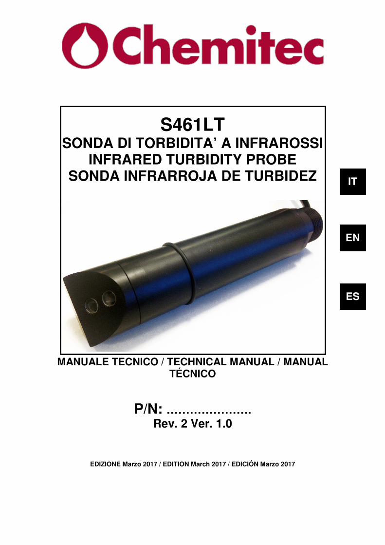
S461LT SONDA DI TORBIDITA’ A INFRAROSSI
INFRARED TURBIDITY PROBE SONDA INFRARROJA DE TURBIDEZ
MANUALE TECNICO / TECHNICAL MANUAL / MANUAL
TÉCNICO
P/N: …………………. Rev. 2 Ver. 1.0
EDIZIONE Marzo 2017 / EDITION March 2017 / EDICIÓN Marzo 2017
IT
EN
ES
SS446611LLTT IInnffrraarreedd TTuurrbbiiddiittyy PPrroobbee
DDaattaa SShheeeett
S461LT Infrared Turbidity Probe – Data Sheet Page 9
The S461LT probe is used for the optical measure of turbidity in pure and process waters up to 100 NTU. The probe uses the 90° scattered light method. Applications • Measure of turbidity in pure and drinkable water • Measure of turbidity in primary, industrial, recirculating water Features and benefits • Reliable concentration measurement using optical measuring process
• Infrared light pulsing beams scattering method • Black rigid PVC sensor body • No mechanically moving parts • Measured value pre-processing in sensor resulting in low signal transmission sensitivity
• Immediate installation and easy manteinance Turbidity measurement with the 90° scattered light method By turbidity we mean the scattered component of a light beam which is diverted away from its original course by optically denser particles in the medium e.g. solid matter particles. Measurements are made using the standardised 90° scattered light method in accordance with ISO 7027 / EN 27027. The measuring method is based on the Tyndall effect. The turbidity of the medium is determined from the amount of scattered light. The transmitted infra-red light beam is scattered by the particles in the medium. The scattered beams are measured by scattered light receivers which are fixed at an angle of 90 to the transmitted light. The measured scattered light signals are converted to frequency signals. The frequency signals are assigned to corresponding turbidity units and solid matter concentrations, and appear in the display.

SS446611LLTT IInnffrraarreedd TTuurrbbiiddiittyy PPrroobbee
DDaattaa SShheeeett
S461LT Infrared Turbidity Probe – Data Sheet Page 10
Principle of 90° scattered beam Measurement:
Is = I0 ⋅⋅⋅⋅ A⋅⋅⋅⋅ C ⋅⋅⋅⋅ f(α)
I0 = Intensity of transmitted light IS = Intensity of scattered light A = Geometrical factor C = Concentration f(α)= Angle correlation P = Particle
Composition of the supply
The supply consists of a single package containing the following parts:
1. 1 S461LT Infrared Turbidity Probe with 10 meter cable 2. 1 Technical manual for instruction
2 1
SS446611LLTT IInnffrraarreedd TTuurrbbiiddiittyy PPrroobbee
DDaattaa SShheeeett
S461LT Infrared Turbidity Probe – Data Sheet Page 11
Calibration of the probe The S461LT probe can be calibrated can be calibrated in several ways: • On two points:
You trace the calibration line by using two known solutions: the first point near 0 NTU and the second to a value as close as possible to the working point.
• First point:
It calibrates the first point of the curve. You enter the calibration menu with two points, but you only perform a calibration of the first. In this way it is possible to align the reading when the read value is lower than 1 NTU, but discordant to a known reference.
• Second point:
It calibrates the second point of the curve. You enter the calibration menu with two points, but you only perform a calibration of the second. In this way it is possible to align the reading when the read value is higher than 1 NTU, but discordant to a known reference.
• Single point:
This calibration mode allows to change the offset of all the straight and must be performed only when the turbidity value of the point that we are calibrating is above 1 NTU, because the probe does not allow to change the offset if the values of turbidity are too low.
Circulate water with known solution, making sure that there are no air bubbles in the circuit: to eliminate them you can create a small pressure partially closing the output stream. The liquid can also stay calm inside the probe holder, but you must be careful to deposit phenomena that could distort the reading. Wait about 4-5 minutes for the reading to stabilize and proceed with calibration from the keyboard by entering the value of the known solution.
SS446611LLTT IInnffrraarreedd TTuurrbbiiddiittyy PPrroobbee
DDaattaa SShheeeett
S461LT Infrared Turbidity Probe – Data Sheet Page 12
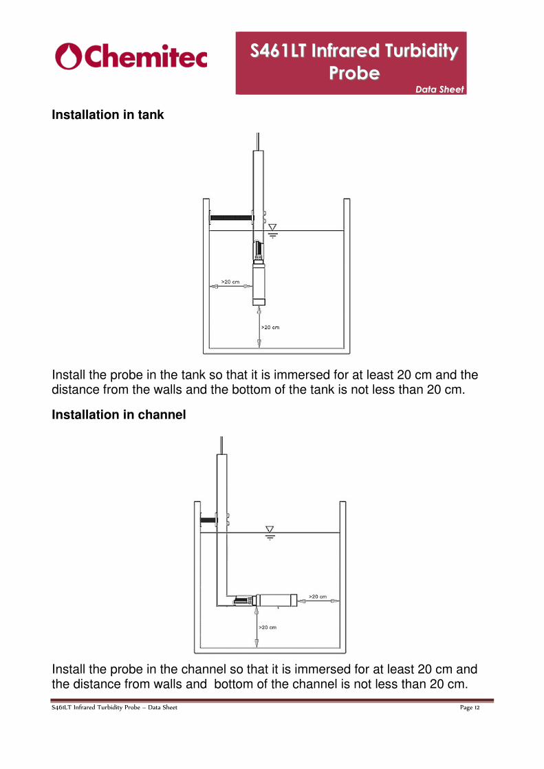
Installation in tank
Install the probe in the tank so that it is immersed for at least 20 cm and the distance from the walls and the bottom of the tank is not less than 20 cm.
Installation in channel
Install the probe in the channel so that it is immersed for at least 20 cm and the distance from walls and bottom of the channel is not less than 20 cm.
SS446611LLTT IInnffrraarreedd TTuurrbbiiddiittyy PPrroobbee
DDaattaa SShheeeett
S461LT Infrared Turbidity Probe – Data Sheet Page 13
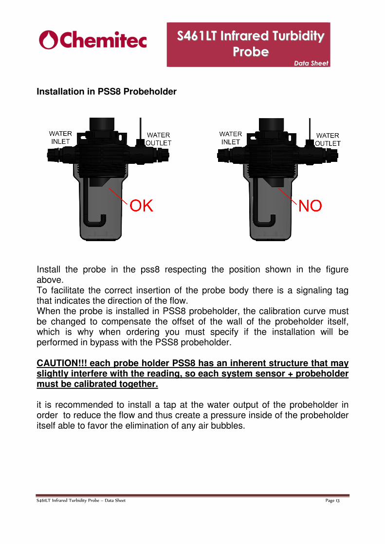
Installation in PSS8 Probeholder
Install the probe in the pss8 respecting the position shown in the figure above. To facilitate the correct insertion of the probe body there is a signaling tag that indicates the direction of the flow. When the probe is installed in PSS8 probeholder, the calibration curve must be changed to compensate the offset of the wall of the probeholder itself, which is why when ordering you must specify if the installation will be performed in bypass with the PSS8 probeholder. CAUTION!!! each probe holder PSS8 has an inherent structure that may slightly interfere with the reading, so each system sensor + probeholder must be calibrated together. it is recommended to install a tap at the water output of the probeholder in order to reduce the flow and thus create a pressure inside of the probeholder itself able to favor the elimination of any air bubbles.
SS446611LLTT IInnffrraarreedd TTuurrbbiiddiittyy PPrroobbee
DDaattaa SShheeeett
S461LT Infrared Turbidity Probe – Data Sheet Page 14
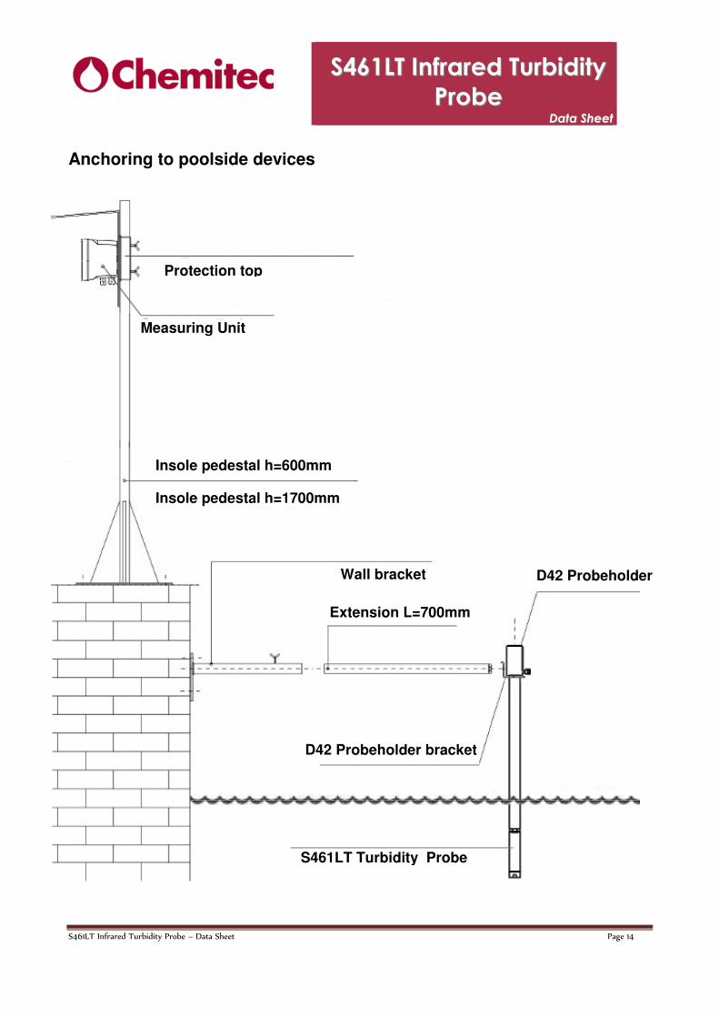
Anchoring to poolside devices
Protection top
Measuring Unit
Insole pedestal h=600mm
Insole pedestal h=1700mm
Wall bracket D42 Probeholder
Extension L=700mm
S461LT Turbidity Probe
D42 Probeholder bracket
SS446611LLTT IInnffrraarreedd TTuurrbbiiddiittyy PPrroobbee
DDaattaa SShheeeett
S461LT Infrared Turbidity Probe – Data Sheet Page 15
Order codes
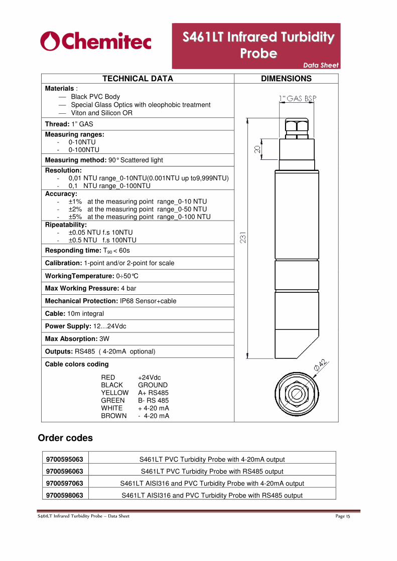
TECHNICAL DATA DIMENSIONS Materials :
Black PVC Body Special Glass Optics with oleophobic treatment Viton and Silicon OR
Thread: 1” GAS
Measuring ranges: - 0-10NTU - 0-100NTU
Measuring method: 90° Scattered light
Resolution: - 0,01 NTU range_0-10NTU(0.001NTU up to9,999NTU) - 0,1 NTU range_0-100NTU
Accuracy: - ±1% at the measuring point range_0-10 NTU - ±2% at the measuring point range_0-50 NTU - ±5% at the measuring point range_0-100 NTU
Ripeatability: - ±0.05 NTU f.s 10NTU - ±0.5 NTU f.s 100NTU
Responding time: T90 < 60s
Calibration: 1-point and/or 2-point for scale
WorkingTemperature: 0÷50°C
Max Working Pressure: 4 bar
Mechanical Protection: IP68 Sensor+cable
Cable: 10m integral
Power Supply: 12…24Vdc
Max Absorption: 3W
Outputs: RS485 ( 4-20mA optional)
Cable colors coding
RED +24Vdc BLACK GROUND YELLOW A+ RS485 GREEN B- RS 485 WHITE + 4-20 mA BROWN - 4-20 mA
9700595063 S461LT PVC Turbidity Probe with 4-20mA output
9700596063 S461LT PVC Turbidity Probe with RS485 output
9700597063 S461LT AISI316 and PVC Turbidity Probe with 4-20mA output
9700598063 S461LT AISI316 and PVC Turbidity Probe with RS485 output