Embed Size (px)
Citation preview

SPECIFICATIONS FOR:
SONOCO PRODUCTS COMPANY -FLEXIBLE DIVISION 2017-ALTERATIONS TO EXISTING PLANT / BUILDING 1691 MATHESON BLVD., MISSISSAUGA, ONTARIO
BINDER A: ARCHITECTURAL, STRUCTURAL MECHANICAL & ELECTRICAL SPECIFICATIONS
Project No. 2017118 2018 01 23 ISSUED FOR TENDER
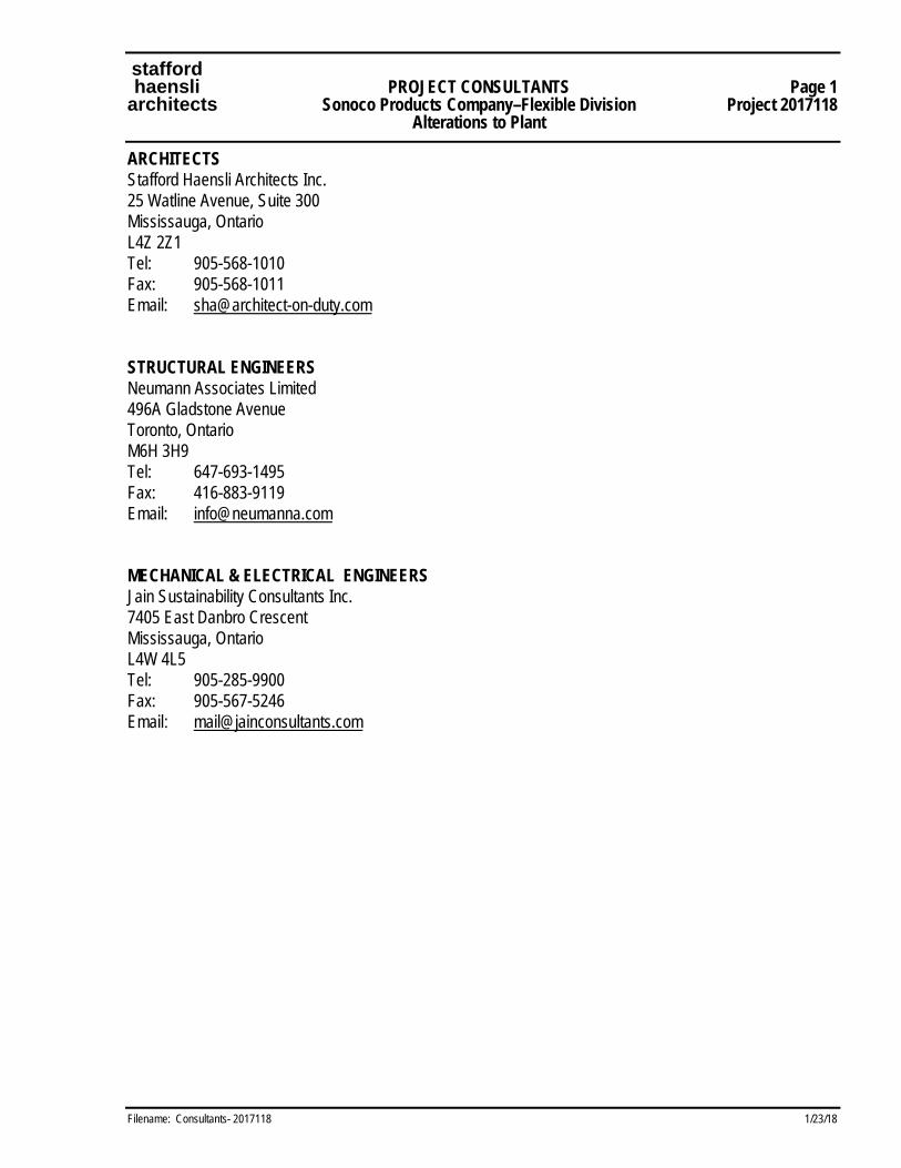
stafford haensli PROJECT CONSULTANTS Page 1 architects Sonoco Products Company–Flexible Division Project 2017118 Alterations to Plant
Filename: Consultants- 2017118 1/23/18
ARCHITECTS Stafford Haensli Architects Inc. 25 Watline Avenue, Suite 300 Mississauga, Ontario L4Z 2Z1 Tel: 905-568-1010 Fax: 905-568-1011 Email: [email protected] STRUCTURAL ENGINEERS Neumann Associates Limited 496A Gladstone Avenue Toronto, Ontario M6H 3H9 Tel: 647-693-1495 Fax: 416-883-9119 Email: [email protected] MECHANICAL & ELECTRICAL ENGINEERS Jain Sustainability Consultants Inc. 7405 East Danbro Crescent Mississauga, Ontario L4W 4L5 Tel: 905-285-9900 Fax: 905-567-5246 Email: [email protected]

stafford 00000 haensli SPECIFICATIONS INDEX Page 1 architects Sonoco Products Company–Flexible Division Project 2017118 Alterations to Plant
Filename: 02.SpecIndex.2017118.doc 1/24/18
BINDER 'A' ARCHITECTURAL / STRUCTURAL SPECIFICATIONS
DIVISION 0 SPECIAL DOCUMENTS Section Title No. of Pages
Document 00045 Invited General Contractors .............................................................................................. 2 Document 00100 Instructions to Bidders (Stipulated Sum) ..................................................................... 10 Document 00300 Tender Form (Stipulated Sum) ........................................................................................ 6 Document 00428 Supplementary Tender Form – General/Architectural: List of Subcontractors, Alternate, Separate, Itemized and Unit Prices ........................ 6 Document 00810 Supplementary Conditions to CCDC Document No.2, 2008 ......................................... 10 White Pages – Division 1
DIVISION 1 GENERAL REQUIREMENTS
01001 Summary of Work ........................................................................................................... 11
01010 General Requirements ..................................................................................................... 46
01120 Electronic Communications and Data Files ....................................................................... 4
01129 Read This First Regarding PDF Files .................................................................................. 2
01400 Construction and Contract Quality Control ....................................................................... 13
DIVISION 2 SITEWORK
02060 Demolition of Structures .................................................................................................... 6
02223 Excavating, Trenching and Backfilling .............................................................................. 11
DIVISION 3 CONCRETE
03000 Division 3: Concrete Work ............................................................................................... 20
03345 Division 3: Concrete Floor Finishes ................................................................................... 5
DIVISION 5 METALS
05130 Structural Steel & Steel Deck .......................................................................................... 18
05500 Metal Fabrications ............................................................................................................. 4

stafford 00000 haensli SPECIFICATIONS INDEX Page 2 architects Sonoco Products Company–Flexible Division Project 2017118 Alterations to Plant
Filename: 02.SpecIndex.2017118.doc 1/24/18
DIVISION 6 WOOD AND PLASTICS
06100 Rough Carpentry ............................................................................................................... 4
DIVISION 7 THERMAL AND MOISTURE PROTECTION
07511 Built-Up Bituminous Roofing ........................................................................................... 19
07620 Metal Flashing and Trim ................................................................................................... 5
07900 Sealants ............................................................................................................................ 5
07950 Air Leakage Sealant .......................................................................................................... 3
DIVISION 8 DOORS AND WINDOWS
08110 Steel Hollow Metal Doors and Frames .............................................................................. 7
08800 Miscellaneous Glass and Glazing ...................................................................................... 5
DIVISION 9 FINISHES
09250 Gypsum Board ................................................................................................................... 7
09910 Painting and Special Coatings ........................................................................................... 7
MECHANICAL / ELECTRICAL SPECIFICATIONS Section Title No. of Pages
DIVISION 15 MECHANICAL
15010 Mechanical General Requirements .................................................................................. 18
15250 Insulation ........................................................................................................................... 6
15400 Plumbing & Drainage ......................................................................................................... 5
15850 Air Distribution ................................................................................................................. 15
DIVISION 16 ELECTRICAL
16010 Electrical General Requirements ........................................................................................ 9
16050 Basic Materials & Methods .............................................................................................. 18
16530 Emergency Lighting System ............................................................................................... 4
END OF SPECIFICATIONS - Project 2017118
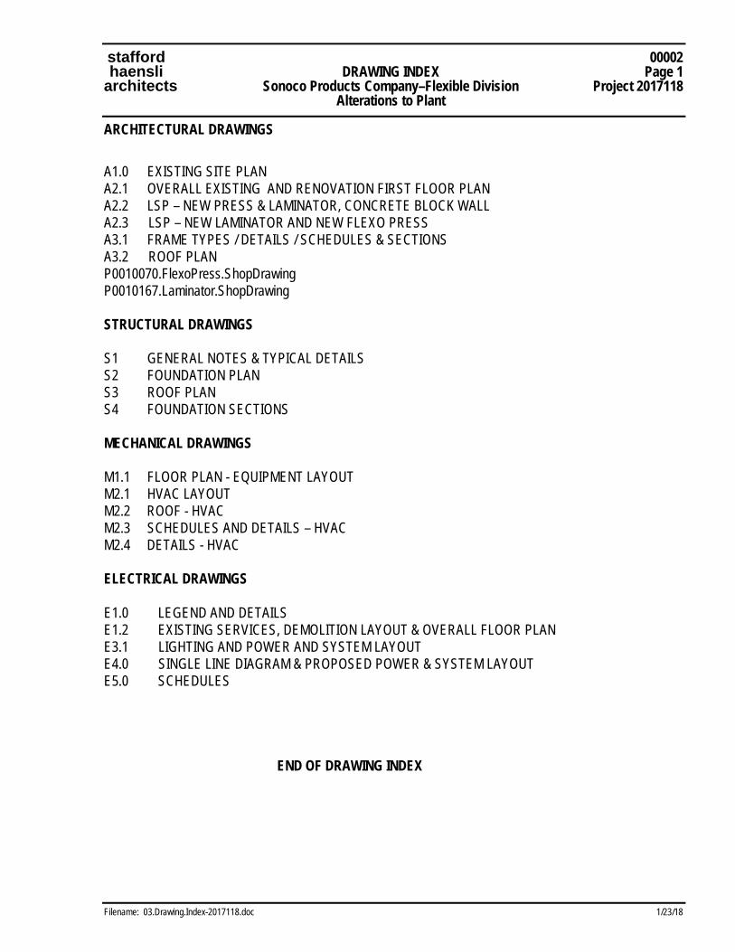
stafford 00002 haensli DRAWING INDEX Page 1 architects Sonoco Products Company–Flexible Division Project 2017118 Alterations to Plant
Filename: 03.Drawing.Index-2017118.doc 1/23/18
ARCHITECTURAL DRAWINGS A1.0 EXISTING SITE PLAN A2.1 OVERALL EXISTING AND RENOVATION FIRST FLOOR PLAN A2.2 LSP – NEW PRESS & LAMINATOR, CONCRETE BLOCK WALL A2.3 LSP – NEW LAMINATOR AND NEW FLEXO PRESS A3.1 FRAME TYPES / DETAILS / SCHEDULES & SECTIONS A3.2 ROOF PLAN P0010070.FlexoPress.ShopDrawing P0010167.Laminator.ShopDrawing STRUCTURAL DRAWINGS
S1 GENERAL NOTES & TYPICAL DETAILS S2 FOUNDATION PLAN S3 ROOF PLAN S4 FOUNDATION SECTIONS MECHANICAL DRAWINGS
M1.1 FLOOR PLAN - EQUIPMENT LAYOUT M2.1 HVAC LAYOUT M2.2 ROOF - HVAC M2.3 SCHEDULES AND DETAILS – HVAC M2.4 DETAILS - HVAC ELECTRICAL DRAWINGS E1.0 LEGEND AND DETAILS E1.2 EXISTING SERVICES, DEMOLITION LAYOUT & OVERALL FLOOR PLAN E3.1 LIGHTING AND POWER AND SYSTEM LAYOUT E4.0 SINGLE LINE DIAGRAM & PROPOSED POWER & SYSTEM LAYOUT E5.0 SCHEDULES END OF DRAWING INDEX
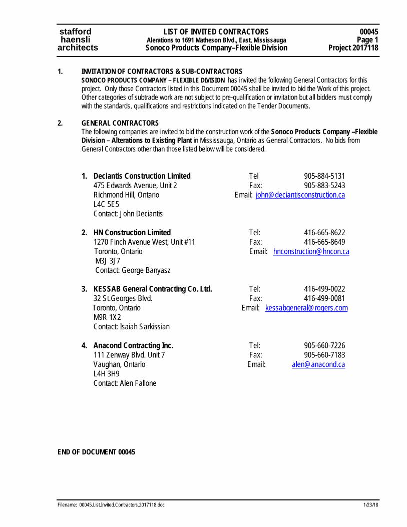
stafford LIST OF INVITED CONTRACTORS 00045 haensli Alerations to 1691 Matheson Blvd., East, Mississauga Page 1 architects Sonoco Products Company–Flexible Division Project 2017118
Filename: 00045.List.Invited.Contractors.2017118.doc 1/23/18
1. INVITATION OF CONTRACTORS & SUB-CONTRACTORS SONOCO PRODUCTS COMPANY – FLEXIBLE DIVISION has invited the following General Contractors for this
project. Only those Contractors listed in this Document 00045 shall be invited to bid the Work of this project. Other categories of subtrade work are not subject to pre-qualification or invitation but all bidders must comply with the standards, qualifications and restrictions indicated on the Tender Documents.
2. GENERAL CONTRACTORS The following companies are invited to bid the construction work of the Sonoco Products Company –Flexible
Division – Alterations to Existing Plant in Mississauga, Ontario as General Contractors. No bids from General Contractors other than those listed below will be considered.
1. Deciantis Construction Limited Tel 905-884-5131 475 Edwards Avenue, Unit 2 Fax: 905-883-5243 Richmond Hill, Ontario Email: [email protected] L4C 5E5 Contact: John Deciantis 2. HN Construction Limited Tel: 416-665-8622 1270 Finch Avenue West, Unit #11 Fax: 416-665-8649
Toronto, Ontario Email: [email protected] M3J 3J7 Contact: George Banyasz 3. KESSAB General Contracting Co. Ltd. Tel: 416-499-0022 32 St.Georges Blvd. Fax: 416-499-0081
Toronto, Ontario Email: [email protected] M9R 1X2 Contact: Isaiah Sarkissian 4. Anacond Contracting Inc. Tel: 905-660-7226 111 Zenway Blvd. Unit 7 Fax: 905-660-7183 Vaughan, Ontario Email: [email protected]
L4H 3H9 Contact: Alen Fallone
END OF DOCUMENT 00045

stafford INSTRUCTIONS TO TENDERERS Document 00100 haensl Sonoco Products Company – Flexible Division Page 1 architects Alterations to Plant Project 2017118
Filename: 00100.InstructBidders.2017118.doc 01/23/18
INSTRUCTIONS TO TENDERERS for SONOCO PRODUCTS COMPANY – FLEXIBLE DIVISION
Instructions for Tendering (Bidding) must be followed implicitly. Any Tender Submission which does not comply with the proposed CCDC2, 2008 Stipulated Price Construction Contract conditions, Supplementary General Conditions (Document 00810), Instructions to Tenderers (this Document 00100) and the Tender Form (Document 00300) will be declared informal and will not be considered. 1. DESCRIPTION 1.1 Work under this Contract shall cover the renovation construction work to be known as
SONOCO PRODUCTS COMPANY – FLEXIBLE DIVISION; ALTERATIONS TO EXISTING PLANT / BUILDING The building municipal address is 1691 Matheson Blvd., in the City of Mississauga, Ontario.
1.2 Work not included in this Contract comprises of the following:
.1 Furniture, Fixtures and Equipment not shown or which is identified as NIC (Not In Contract) on Contract Documents.
2. CONTRACT DOCUMENTS 2.1 Consult all Contract Documents consisting of the following:
.1 Instructions to Tenderers (Document 00100) .2 Tender Form and Appendices (Document 00300) .3 Supplementary Tender Form(s) (Document 00428) .4 Canadian Standard Construction Document CCDC2, 2008 Stipulated Price-Contract .5 Supplementary Contract Requirements (Document 00810) .6 General Requirements - Division 1 .7 Specifications as listed in the Specification Index .8 Drawings and Detail Sheets as listed in the Drawing and Detail Sheet Index .9 Any Addenda issued prior to the closing date/time of Tender
3. OWNER, ARCHITECT AND CONSULTANTS 3.1 The Business Owner (Owner of the Construction Contract) is: Sonoco Products Company P.O. Box 160-E20 1 North Second Street Hartsville, South Carolina 29550 Telephone: (843) 383-7000 Fax: (843) 339-6058
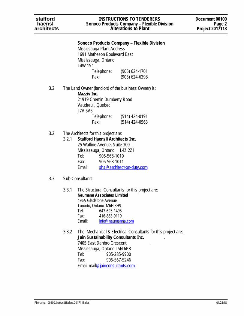
stafford INSTRUCTIONS TO TENDERERS Document 00100 haensl Sonoco Products Company – Flexible Division Page 2 architects Alterations to Plant Project 2017118
Filename: 00100.InstructBidders.2017118.doc 01/23/18
Sonoco Products Company – Flexible Division Mississauga Plant Address 1691 Matheson Boulevard East Mississauga, Ontario L4W 1S1 Telephone: (905) 624-1701 Fax: (905) 624-6398 3.2 The Land Owner (landlord of the business Owner) is: Mazziv Inc. 21919 Chemin Dumberry Road Vaudreuil, Quebec J7V 5V5 Telephone: (514) 424-0191 Fax: (514) 424-0563 3.2 The Architects for this project are: 3.2.1 Stafford Haensli Architects Inc. 25 Watline Avenue, Suite 300 Mississauga, Ontario L4Z 2Z1 Tel: 905-568-1010 Fax: 905-568-1011
Email: [email protected]
3.3 Sub-Consultants: 3.3.1 The Structural Consultants for this project are:
Neumann Associates Limited 496A Gladstone Avenue Toronto, Ontario M6H 3H9 Tel: 647-693-1495 Fax: 416-883-9119 Email: [email protected]
3.3.2 The Mechanical & Electrical Consultants for this project are: Jain Sustainability Consultants Inc. . 7405 East Danbro Crescent . Mississauga, Ontario L5N 6P8 Tel: 905-285-9900 Fax: 905-567-5246 Emai: [email protected]
stafford INSTRUCTIONS TO TENDERERS Document 00100 haensl Sonoco Products Company – Flexible Division Page 3 architects Alterations to Plant Project 2017118
Filename: 00100.InstructBidders.2017118.doc 01/23/18
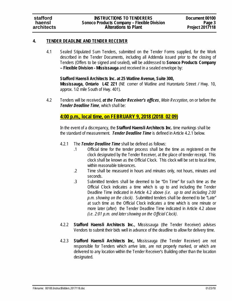
4. TENDER DEADLINE AND TENDER RECEIVER 4.1 Sealed Stipulated Sum Tenders, submitted on the Tender Forms supplied, for the Work
described in the Tender Documents, including all Addenda issued prior to the closing of Tenders (Offers to be signed and sealed), will be addressed to Sonoco Products Company – Flexible Division - Mississauga and received in a sealed envelope by:
Stafford Haensli Architects Inc. at 25 Watline Avenue, Suite 300, Mississauga, Ontario L4Z 2Z1 (NE corner of Watline and Hurontario Street / Hwy. 10,
approx. 1/2 mile South of Hwy. 401). 4.2 Tenders will be received, at the Tender Receiver’s offices, Main Reception, on or before the
Tender Deadline Time, which shall be:
4:00 p.m., local time, on FEBRUARY 9, 2018 (2018 02 09)
In the event of a discrepancy, the Stafford Haensli Architects Inc. time markings shall be the standard of measurement. Tender Deadline Time is defined in Article 4.2.1 below.
4.2.1 The Tender Deadline Time shall be defined as follows:
.1 Official time for the tender process shall be the time as registered on the clock designated by the Tender Receiver, at the place of tender receipt. This clock shall be known as the Official Clock. This clock will be set to local time, within reasonable tolerances.
.2 Time shall be measured in hours and minutes only, not hours, minutes and seconds.
.3 Submitted tenders shall be deemed to be “On Time” for such time as the Official Clock indicates a time which is up to and including the Tender Deadline Time indicated in Article 4.2 above (i.e. up to and including 2:00 p.m. showing on the clock). Submitted tenders shall be deemed to be “Late” at such time as the Official Clock indicates a time which is one minute or more later (after) the Tender Deadline Time indicated in Article 4.2 above (i.e. 2:01 p.m. and later showing on the Official Clock).
4.2.2 Stafford Haensli Architects Inc., Mississauga (the Tender Receiver) advises
Vendors to submit their bids well in advance of the deadline to allow for delivery time.
4.2.3 Stafford Haensli Architects Inc, Mississauga (the Tender Receiver) are not responsible for Tenders which arrive late, are not properly marked, or which are delivered to any location within the Tender Receiver’s Building other than the location designated.
stafford INSTRUCTIONS TO TENDERERS Document 00100 haensl Sonoco Products Company – Flexible Division Page 4 architects Alterations to Plant Project 2017118
Filename: 00100.InstructBidders.2017118.doc 01/23/18
4.3 Tenders received after the time and date specified above and/or received at any location other than those specified WILL NOT BE ACCEPTED and the un-opened Tenders will be returned.
4.4 Tender shall be submitted for project on forms provided by the Consultant and shall be
marked on the outside of a 9”x 12” sealed envelope with the contractors name, address and phone number in the upper corner and the following:
Tender for Sonoco Products Company – Flexible Division –
Alterations to Plant for Sonoco Mississauga
4.5 All information requested (Blanks) on Document 00300 – Tender Form PLUS Agreement to Bond shall be fully completed. Failure to provide one or more items of requested information in full may, at the discretion of the Owner, result in rejection of the Tender.
4.6 PLEASE NOTE: The Tender Form is structured to list tender amounts in both Canadian
Dollars (CDN$) and United States Dollars (US$) (the contract will be paid in US$. Please indicate the conversion factor used – this factor will be maintained throughout the duration of the contract.
4.7 The Tender Form shall be signed by the appropriate officers of the Contractor’s firm.
Incorporated companies shall affix their corporate seal under the hands of their authorized officers. Drawings and specifications shall be returned to the Consultant within 10 days of the closing of tenders. A second copy of the Tender Form should be retained by the Bidder.
4.8 Tenders shall be valid for Thirty (30) calendar days from the date of closing above. It must
be clearly understood that the final acceptance of this contract is subject to approvals of the Owner and other bodies and these may delay final approval. There will be no adjustments in the tendered price for a period of Thirty (30) calendar days from receipt of tenders due to delays resulting from factors beyond the Contractor’s control.
5. SEPARATE AND/OR ALTERNATE PRICES 5.1 Separate and/or Alternate Prices, if any, are requested on Document 00300 – Tender Form.
Submission of Separate and/or Alternate Prices is, therefore, due on or before the Tender Deadline Time, as defined above.
6. TENDER OPENING, TENDER ACCEPTANCE, TENDER REJECTION 6.1 The Owner will open all tenders in private on the date of the closing of the tender and
immediately after the Tender Deadline Time. Tenderers and other interested parties may not attend the opening, unless specifically invited.
stafford INSTRUCTIONS TO TENDERERS Document 00100 haensl Sonoco Products Company – Flexible Division Page 5 architects Alterations to Plant Project 2017118
Filename: 00100.InstructBidders.2017118.doc 01/23/18
6.2 The Owner reserves the right to reject any or all proposals submitted without explanations, and to waive any informalities in same. The lowest or any tender shall not necessarily be accepted.
7. ERRORS IN TENDER SUBMISSIONS 7.1 The Owner shall not entertain requests for gratuitous payments arising from errors alleged to
have been made in a tender which the Owner has accepted. 8. BIDDING ASSUMPTIONS 8.1 All bids submitted, including bids by Sub-Contractors, are assumed to be based upon the
complete set of Tender and Contract Documents. No alterations in prices for items of Work will be considered if it is determined by the Owner, the Consultants or the Contractor that bids were not based on the complete set of documents (e.g. bids based upon Specifications but not on Drawings and vice-versa; bids based upon partial group of Drawings; or assumption of acceptance of work previously done for the Owner).
9. ON-SITE MEETING DURING TENDER PERIOD 9.1 The building site is located at Sonoco Products Company – Flexible Division 1691
Matheson Blvd., Mississauga, Ontario, will be open and accessible to General Contractors and Subcontractor bidders general inspection and for a “Walkthrough Meeting” on:
Tuesday January 30, 2018 (2018 01 30) at 2:00 p.m.
Please meet at the entrance to the site. Tenderers may tour the site (to view existing
conditions, take measurements, photographs, etc.). ***All Contractor or subtrades must wear safety boots.
9.2 Representatives of the Consultants will be present on site. They will be available to walk
through the existing site and view the existing temporary (outdoor) substation equipment with the Tenderers, describe the work in general terms, answer questions, etc.
9.3 No special equipment such as ladders, flashlights, measuring tapes, etc. will be provided at
the site but Tenderers may bring their own equipment if so desired. 9.4 No verbal communication, answers to questions, descriptions, etc. which takes place during
the site meeting / site review period shall be taken or construed as forming a change to the intent or scope of the printed Tender Documents. Any changes or clarifications resulting from on site discussions shall be issued in the form of a written Addendum if they are to be
stafford INSTRUCTIONS TO TENDERERS Document 00100 haensl Sonoco Products Company – Flexible Division Page 6 architects Alterations to Plant Project 2017118
Filename: 00100.InstructBidders.2017118.doc 01/23/18
implemented by those tendering this project. No other form of project change/clarification communication will be issued, accepted or acknowledged.
10. COMPLETION DATES 10.1 Tenders must include all costs involved in having the contract “Fit for Legal Occupancy and
Substantial Performance” not later than:
.1 Foundations for New Press/Laminator, Masonry wall, Exhaust & HVAC: ready to hand-over to Sonoco Products Company – Flexible Division, Mississauga - “Substantial Performance” not later than May 25, 2018 (2018 05 25).
.2 Foundations for New Press/Laminator, Masonry wall, exhaust & HVAC: ready to
hand-over to Sonoco Products Company – Flexible Division, Mississauga - “Fit for Occupancy” not later than July 15, 2018 (2018 07 15).
11. SUPPLEMENTARY INFORMATION FORM (Document 00428) 11.1 SUBMISSION REQUIREMENTS:
11.1.1 Document 00428, as described below, shall be submitted by all General Contractor Bidders.
11.1.2 Document 00428 shall be submitted within 24 hours of the close of General
Tenders (i.e. not later than 2:00 p.m., local time, on the day following the Tender Close).
11.1.3 Submit via Email (PDF Attachment) to the Architects’ office (Stafford Haensli Architects Inc. – Email [email protected]. Provide the original documents (later), if so requested. Time / Date as shown on Email header will be taken as time of receipt.
11.2 ARCHITECTURAL SUPPLEMENTARY TENDER INFORMATION FORM (Document 00428) 11.2.1 General Contractor Bidders to submit the Architectural Supplementary Tender Information
Form (Document 00428). Document 00428 may request any or all of the following items / information:
.1 ITEMIZED PRICES: Each price expressed shall be the amount already included in
the Base Bid Tender Amount. Itemized Prices are required by the Owner for proper tender analysis and/or to administer project funding from multiple budgets. It is
stafford INSTRUCTIONS TO TENDERERS Document 00100 haensl Sonoco Products Company – Flexible Division Page 7 architects Alterations to Plant Project 2017118
Filename: 00100.InstructBidders.2017118.doc 01/23/18
requested that Itemized Prices be as accurate as possible. Refer to Document 00428 for additional requirements for Itemized Prices.
.2 UNIT PRICES: Unit prices requested/supplied will apply in connection with approved additions or deductions to the contract; unit prices shall include statutory charges, overhead and profit. Unit prices shall not include HST. Unit Prices for Extras/Additions shall not exceed process for Credits/Deductions by more than 25%. Refer to Document 00428 for additional requirements for Unit Prices.
.3 LIST OF PROPOSED SUB-CONTRACTORS: The Tenderer shall name in the list
the Sub-Contractors proposed to perform the Work under the contract. No substitutions to these lists shall be made without the written approval of the Consultants and/or the Owner. Refer to Document 00428 for additional requirements for the List of Proposed Sub-Contractors.
12. ALTERNATIVES AND ALTERNATIVE PRICES
12.1 There are two opportunities for a Bidder to identify (optional) Alternatives in the Tender Submission. .1 The first method is to identify proposed Alternatives at the time of the Tender
Submission on the Tender Form (Document 00300) in the spaces provided. .2 The second is to identify Alternatives at the time of the Supplementary Information
Forms Submission (24 hours following close of Tenders) on the Supplementary Information Form (Document 00428). If no spaces are provided for listing of Alternatives, the Bidder may attach additional pages and/or may write-in the proposed information.
13. BID BOND, PERFORMANCE BOND, LABOUR & MATERIAL PAYMENT BOND 13.1 A Bid Bond or similar surety device is not required for this tender. 13.2 Each tender shall be accompanied by a Agreement to Bond. Bonds shall be in the most
recent form approved by the Canadian Construction Association from a Surety Company which is acceptable to the Owner. Tenders not accompanied by a Bid Bond and Agreement to Bond will be rejected.
13.3 The Tender Submission shall be accompanied by an Agreement from the Surety Company
that a 50% Performance Bond and a 50% Labour and Material Payment Bond will be issued to the Bidder if he is awarded the contract. The cost of the Bonds shall be included in the amount of the Tender. Refer to the standard contract document CCDC2, 2008 - Stipulated Price Contract, for further information.
stafford INSTRUCTIONS TO TENDERERS Document 00100 haensl Sonoco Products Company – Flexible Division Page 8 architects Alterations to Plant Project 2017118
Filename: 00100.InstructBidders.2017118.doc 01/23/18
13.6 A Performance Bond, equal to 50% of the Stipulated Sum Tender Amount, shall be supplied through a Surety Company or Insurance Company approved by the Consultant and the Owner according to terms and conditions acceptable to the Owner and the Consultant.
13.7 A Labour and Material Payment Bond, equal to 50% of Stipulated Sum Tender Amount, shall
be provided through a Surety Company or Insurance Company approved by the Consultant and the Owner according to terms and conditions acceptable to the Owner and the Consultant. Said Bond shall state that the Owner will not be held responsible if payment to Sub-Contractors, as certified due by the Consultant, is not made by the General Contractor when due.
13.8 On completion of the work, the Performance Bond shall remain in force as a MAINTENANCE
BOND for a period of one (1) year from the date of acceptance of the building by the Owner. It shall form a guarantee of workmanship and materials for the one (1) year period.
13.9 The Tenderer to whom the Contract is awarded must properly sign and deliver the Contract
and furnish a satisfactory Performance Bond, Labour and Material Payment Bond, Insurance Certificate and Workers’ Compensation Board (WSIB) Certificate within ten (10) Working Days of acceptance of the Tender by the Owner, or forfeit the Bid Bond.
14. TENDERERS 14.1 Persons or firms submitting tender proposals shall be actually engaged as their recognized
business in the lines of work required by the specifications, and shall be able to refer to work of a similar character which has been satisfactorily performed by them.
15. FAIR WAGE AND LABOUR CONDITIONS 15.1 Rate of wages, hours and conditions of work shall be in accordance with Provincial Codes
and as generally recognized and accepted in the locality. Building mechanics and labourers resident in the district are to be employed where suitable.
15.2 Labour forces employed on the site may have compatible affiliation with any labour
organization. Union contract itself is not prerequisite. 16. DISCREPANCIES AND OMISSIONS 16.1 Tenderers, including Sub-Contractors, finding specified items unavailable, finding
discrepancies in, or omissions from, the drawings or specifications or other contract documents, or having any doubt as to the intent or meaning of any part thereof, shall at once notify the Consultant, who will issue an Addendum to all Tenderers in explanation of the inquiry if necessary.

stafford INSTRUCTIONS TO TENDERERS Document 00100 haensl Sonoco Products Company – Flexible Division Page 9 architects Alterations to Plant Project 2017118
Filename: 00100.InstructBidders.2017118.doc 01/23/18
16.2 All definitions, explanations, corrections or additional information will be issued by the
Consultant during the time of bidding in the form of typewritten addenda and such addenda will be available to all Tenderers. These shall become part of the contract documents and must be shown on the Form of Tender as having been received.
16.3 No verbal or electronic email instructions and/or changes will be issued during the Tender
Period which would alter the Tender Price and any claims that such instructions and/or changes were issued verbally will not be recognized.
17. INQUIRIES AND INSTRUCTIONS 17.1 All correspondence, inquiries, instructions, etc., in connection with the work shall be made
through the office of the Consultant in writing delivered by courier, mailed or faxed to Stafford Haensli Architects Inc., to the attention of:
Mr. Lucy Bandiera, Stafford Haensli Architects Inc.
Tel.: 905-568-1010 ext 223, Fax: 905-568-1011 Email: [email protected]
18. EXAMINATION OF SITE 18.1 Proposals shall include the cost imposed by existing conditions and limitations of site and the
accepted proposal shall be held to have included such costs. NO ALLOWANCE WILL BE MADE FOR FAILURE TO EXAMINE THE EXISTING SITE AND RELATED CONDITIONS.
18.2 The levels and other information shown on the drawings are furnished in good faith for the
guidance of the Contractor, but shall in no way relieve him of the responsibility of ascertaining to his own satisfaction the nature of all conditions at the site.
19. BUILDING PERMIT FEES & OTHER FEES 19.1 Building Permit has been applied for by the Consultant and has been paid by Sonoco
Products Company – Flexible Division
19.2 The Contractor must apply for and pay ALL other necessary fees, deposits and charges related to Municipal, Provincial and Federal Requirements. Please note that these amounts are not included in the project Cash Allowance but are to be included in the Stipulated Sum Tender Amount. The General Contractor is responsible for determining the amounts of some of these permits, fees, etc., but not be limited to:
.1 Mud Tracking Deposits .2 Dumping and/or Disposal Permits
stafford INSTRUCTIONS TO TENDERERS Document 00100 haensl Sonoco Products Company – Flexible Division Page 10 architects Alterations to Plant Project 2017118
Filename: 00100.InstructBidders.2017118.doc 01/23/18
20. CONTRACT DOCUMENTS 20.1 The Contract shall be subject to the Requirements of the Canadian Standard Construction
Document CCDC2, 2008 Stipulated Price-Contract. The successful bidder must sign the “Agreement between Owner and Contractor” using this document and these specifications and drawings, within ten (10) Working Days of notification of award. The Contractor shall not be entitled to any payment until this document is signed.
20.2 All Contractors will be held to have examined and made themselves familiar with the various
articles of these Standard Documents and shall be as binding for all sections of the following specifications as though written in full therein.
21. DEPOSITS REQUIRED FOR TENDER DOCUMENTS 21.1 PDF Tender File Documents: The Consultants will make available the Tender Documents
(drawings, specifications and Bid Documents) on Compact Disk or email all files in PDF format.
22. SALES TAX - HST 22.1 The tender amount shall not include federal/provincial Harmonized Sales Tax (HST). 22.2 All other prices requested throughout the Tender Documents (Separate Prices, Alternate
Prices, Itemized Prices, Unit Prices, Project Cost Breakdown prices, etc.) shall be listed excluding Harmonized Sales Tax (HST).
22.3 The tender amount shall include all other applicable excise taxes, custom duties, freight,
exchange and all other charges in effect and known to come into effect during the construction of the building described in this Contract.
22.4 The successful Bidder must provide his HST Registration Number and each request for
payment must show this number and the amount of HST payable. 23. LONG DELIVERY BUILDING COMPONENTS
23.1 Bidders should note that the Consultants have identified below, building components that are expected to have long delivery dates. These components are to be purchased (i.e. Purchase Order secured and Shop Drawing procedures initiated) by the General Contractor and or Sub-Contractors immediately upon award of Contract. 1. Roof Top Unit
END OF INSTRUCTIONS TO TENDERERS – Document 00100
stafford TENDER FORM Document 00300 haensli Sonoco Products Company – Flexible Division Page 1 architects Alteration to Plant Project 2017118
File: 00300.TenderForm.2017118.doc 1/23/18
TENDER FORM For SONOCO PRODUCTS COMPANY – FLEXIBLE DIVISION
ALTERATIONS TO EXISTING PLANT / BUILDING 1.1 BIDDER INFORMATION NAME OF BIDDER: .............................................................................................................................................. (Firm Name) .............................................................................................................................................. (Address) .............................................................................................................................................. ............................................................. (Telephone) ......................................................... (Fax) .............................................................................................................................................. (Email) TO: Sonoco Products Company – Flexible Division Mississauga Plant Address 1691 Matheson Boulevard East Mississauga, Ontario, L4W 1S1 1.2 EXAMINATION OF TENDER DOCUMENTS: I/WE DECLARE that we have carefully examined all Drawings and Specifications (including
Architectural, Structural, Mechanical, Electrical, Civil, Landscaping as applicable) and have carefully examined the Instructions to Tenderers, Canadian Standard Construction Document CCDC2, 2008 Stipulated Price-Contract, all other identified contract documents, and all Addenda as listed below;
I/WE FURTHER DECLARE that our tender submission acknowledges the following Addenda issued
prior to the close of tenders (list all Addenda by number): .................................................................... I/WE FURTHER DECLARE that we have visited and carefully examined the existing building, the
existing building site, the surrounding properties and municipal lands as they relate to the subject property, as well as all of the Contract Documents relating to existing conditions, including surveys and geotechnical reports, as applicable to the Work of this Contract;
stafford TENDER FORM Document 00300 haensli Sonoco Products Company – Flexible Division Page 2 architects Alteration to Plant Project 2017118
File: 00300.TenderForm.2017118.doc 1/23/18
1.3 STIPULATED SUM TENDER AMOUNT:
I/WE, the undersigned, agree to provide all materials, labour, plant, equipment and services necessary to perform the Sonoco Products Company-Flexible Packaging – Alterations to Plant, ENTIRE PROJECT WORK (as descxribed and illustrated on the Tender Documents), including all trades, all in accordance with the Tender and Contract Documents, including specified Cash Allowances and Contingency Allowances as indicated in item 1.4 below. Our Stipulated Sum Tender Amount includes all applicable Federal and Provincial Sales and Excise Taxes, Customs Duties, Freight, Exchange, costs of Bonds, Insurances and all other charges, but excludes Federal/Provincial Harmonized Sales Tax (HST).
We Agree to complete the Work in accordance with the requirements of the Tender and Contract Documents for the Stipulated Sum Tender Amount of:
($ ) Canadian Dollars, Excluding HST.
($ ) U.S. Dollars.
We hereby confirm that the conversion factor for the above quotations (which must be within 0.5% of current money market conversion factor on the day of Tender Close) is: $1.00 US = $_________ CDN (example: $1.00 US = $1.52 CDN)
1.4 CONTINGENCY AND CASH ALLOWANCES
The Stipulated Sum Tender Amount includes the specified Contingency Allowance in the amount of Ten Thousand Dollars ($10,000.00). (Note: Contingency Allowance amounts do not include HST.) The Stipulated Sum Tender Amount includes the specified Cash Allowance in the amount of Ten Thousand Dollars ($10,000.00). (Note: Cash Allowance amounts do not include HST.)
1.5 TENDER VALIDITY
I/WE, are submitting a valid tender and will enter into a formal contract if we are notified in writing of our Tender acceptance by the Board within Thirty (30) calendar days from the close of the Tenders.
stafford TENDER FORM Document 00300 haensli Sonoco Products Company – Flexible Division Page 3 architects Alteration to Plant Project 2017118
File: 00300.TenderForm.2017118.doc 1/23/18
1.6 BID BOND/AGREEMENT TO BOND/LETTER OF CREDIT .
I/WE, enclose an Agreement to Bond stating that the Surety Company will issue a 50% Performance Bond and a 50% Labour and Material Payment Bond, if our submitted Tender is successful and the Board awards the Construction Contract to our Firm. Both of the above documents are issued by an acceptable Surety Company.
I/WE, further acknowledge and will comply with the special provisions specified with respect to the wording and/or conditions under which the Performance Bond may be invoked and remain in force as a Maintenance Bond. These special conditions are specified in the Instructions to Tenderers (Document 00100) and documented in the enclosed Supplementary Conditions (Document 00810). I/WE, further acknowledge and will comply with the terms and conditions of the Project Occupancy Requirements as outlined in the specifications and/or the CCDC2, 2008 Stipulated Price Contract and as listed in the enclosed Supplementary Conditions (Document 00810).
1.7 UNDERTAKING I/WE, the Bidder, solemnly undertake, as an integral part of our proposal and tender to:
.1 Foundations for New Press/Laminator, Masonry wall, Exhaust & HVAC: ready to hand-over to Sonoco Products Company – Flexible Division, Mississauga - “Substantial Performance” not later than May 25, 2018 (2018 05 25).
.2 Foundations for New Press/Laminator, Masonry wall, exhaust & HVAC: ready to
hand-over to Sonoco Products Company – Flexible Division, Mississauga - “Fit for Occupancy” not later than July 15, 2018 (2018 07 15).
I/WE, confirm that all appropriate costs, such as winter heat, inclement weather protection and all overtime costs for all trades to meet the aforementioned schedule etc., have been included in our Stipulated Sum Tender Amount to achieve this date.
1.8 CONSTRUCTION SCHEDULE
If notified of the acceptance of this Tender via a Letter of Intent issued by the Owner, we, the Bidder, the undersigned, will sign, seal and deliver the executed Contract Documents within ten (10) Working Days of notification of award and will proceed with construction of the Work within seven (7) calendar days of receiving instructions to commence work.
1.9 FEE FOR CHANGES IN THE WORK
It is agreed and understood that fees and charges with respect to contract changes, as referred to in Canadian Standard Construction Document CCDC2, 2008 Stipulated Price-Contract, including any
stafford TENDER FORM Document 00300 haensli Sonoco Products Company – Flexible Division Page 4 architects Alteration to Plant Project 2017118
File: 00300.TenderForm.2017118.doc 1/23/18
amendments thereto by Supplementary Conditions (Document 00810) to said contract, will apply to changes in the Contract not covered by Unit Prices.
1.10 CONSTRUCTION SAFETY
We, the Bidder, covenant and agree to comply with all statutory and other obligations, including without limitation, the provisions of the Occupational Health and Safety Act (Ontario) and all Regulations thereto, and all amending and successor legislation, including without limitation, Bill 208 (the “Act”), latest revisions, in connection with all work performed by either the Contractor, Sub-Contractors, or any Other Contractor on, or in connection with, the Project. I/WE, the Bidder, further covenant and agree that, if awarded the Contract, we will abide by all of the requirements with respect to Construction Safety in Division 1 – General Requirements of the Specifications and, for the purposes of this Contract, we agree to be the “Constructor” of the Project within the meaning of the Act. As such, we shall assume all the obligations and responsibilities, and observe all construction safety requirements, procedures and duties of inspection imposed by the Act on the “Constructor”. This responsibility shall extend to all Work and services performed by us, our Sub-Contractors and Other Contractors on or in connection with the Project.
1.11 SUBMISSION OF SUPPLEMENTARY INFORMATION FORMS
I/WE, shall submit, within 24 hours of the Close of Tenders, the following fully completed documentation: .1 Document 00428 – Architectural Supplementary Information Form (Itemized Prices, Unit Prices, List of Proposed Sub-Contractors)
stafford TENDER FORM Document 00300 haensli Sonoco Products Company – Flexible Division Page 5 architects Alteration to Plant Project 2017118
File: 00300.TenderForm.2017118.doc 1/23/18
1.12 PROPOSED ALTERNATIVES (Products/Services/Prices) - PROPOSED BY TENDERER (Optional – Not Requested by Consultant) .1 We are submitting Proposed Alternatives (Products and/or Assemblies and/or Proposed
Methods) to the specified work as a separate document attached to this Tender Form or as listed below. The proposed alternatives are expressed as credits or extras to the Stipulated Sum Tender Amount and may be added to or subtracted from the amount of the Contract consistent with their acceptance or rejection by the Owner (Prices do not include HST). The following Alternatives are proposed:
.1 Proposed Alternative #1: Manufacturer/Product ................................................................................................... Installer/Dealer ............................................................................................................. CREDIT: $ .............................................................................................. EXTRA: $ .............................................................................................. .2 Proposed Alternative #2: Manufacturer/Product ................................................................................................... Installer/Dealer ............................................................................................................. CREDIT: $ .............................................................................................. EXTRA : $ .............................................................................................. 1.13 DECLARATION OF NO CONFLICT I/WE, declare that this Tender submission is made in good faith and without any connection,
knowledge, comparison of figures, or arrangement with any other company, firm or person making a Tender submission for the same Work and is, in all respects, fair and without collusion with any other bidder for this contract and without fraud.

stafford TENDER FORM Document 00300 haensli Sonoco Products Company – Flexible Division Page 6 architects Alteration to Plant Project 2017118
File: 00300.TenderForm.2017118.doc 1/23/18
1.14 SIGNING OF TENDER We are submitting this stipulated sum tender under Corporate Seal as a limited company or witnessed
as an individual or partnership. ................................................................................................................................................................. Name of Company ................................................................................................................................................................. ................................................................................................................................................................. Address of Company ................................................................................................................................................................. Name and Position of Signator (print clearly) ................................................................................................................................................................. Signature of Authorized Officer of Company ................................................................................................................................................................. Telephone Fax ................................................................................................................................................................. Email ........................................................................... Name of Witness ............................................................................. ........................................................................... Company Seal Signature of Witness
Dated at ................................................ ............... on ................................................... 2018
END OF TENDER FORM - DOCUMENT 00300
stafford ARCHITECTURAL SUPPLEMENTARY INFORMATION FORM: Document 00428 haensli Sonoco Products Company – Flexible Division Page 1 architects Alteration to Plant Project 2017118
Filename: 00428.Arch.Suppl.Info.Form.2017118.doc 1/23/18
1. GENERAL 1.1 This Document 00428 – Architectural Supplementary Information Form is to be submitted by all the bidding
General Contractor Bidders. Submission of this form plus other information requested elsewhere in the Tender Documents is required within 24 hours of the close of general tenders.
1.2 Information required to be submitted within 24 hours of general tender close:
.1 Document 00428 - Architectural Supplementary Information Form (this document) 1.3 Information requested on Document 00428 are needed to assist with Owners’ and Consultants’ project control
and project monitoring functions. It is required that ALL information requested (i.e. blanks to be filled in) be provided.
2. SUBMISSION OF ALTERNATE, SEPARATE, ITEMIZED PRICES
.1 I/We the undersigned offer the Separate Prices, Itemized Prices and Alternative Prices described below. I/We agree that:
.1 All prices submitted take into consideration and allow for changes and adjustments in
other work as may be necessary to provide a finished and functional result, unless specifically indicated otherwise.
.2 “Alternative Prices" are for work that is not included in the bid price offered in the Bid Form but which the Owner may substitute for Work which is included in the bid price, for the amount quoted below. I/We agree that if no price is shown for work for which an Alternative Price is required, it shall mean the substitute work is offered to the Owner at no change in the bid price.
.3 “Separate Prices" are for work that is not included in the bid price offered in the Bid
Form but which the Owner may add for the amount quoted below. I/We agree that if no price is shown for work for which a Separate Price is required, it shall mean that the work is offered to the Owner at no increase in the bid price.
.4 “Itemized Prices" are for Work that is included in the bid price offered in the Bid Form
but which the Owner may delete for the amount quoted below. I/We agree that if no price is shown for Work for which an Itemized Price is required, it shall mean that the Work is to be deleted without a change in the bid price.
.2 Prices listed hereunder do not include Goods and Services Tax (GST), Ontario Provincial Sales Tax (PST) or Ontario Provincial/Federal Harmonized Sales Tax (HST) but include all other eligible taxes, fees duties and charges.
3. ITEMIZED PRICES
stafford ARCHITECTURAL SUPPLEMENTARY INFORMATION FORM: Document 00428 haensli Sonoco Products Company – Flexible Division Page 2 architects Alteration to Plant Project 2017118
Filename: 00428.Arch.Suppl.Info.Form.2017118.doc 1/23/18
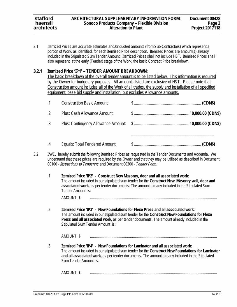
3.1 Itemized Prices are accurate estimates and/or quoted amounts (from Sub-Contractors) which represent a
portion of Work, as identified, for each Itemized Price description. Itemized Prices are amount(s) already included in the Stipulated Sum Tender Amount. Itemized Prices shall not include HST. Itemized Prices shall also represent, at the early (Tender) stage of the Work, the basic Contract Price breakdown.
3.2.1 Itemized Price ‘IP1’ – TENDER AMOUNT BREAKDOWN: The basic breakdown of the overall tender amount is to be listed below. This information is required by the Owner for budgetary purposes. All amounts listed are exclusive of HST. Please note that Construction amount includes all of the Work of all trades, the supply and installation of all specified equipment, base bid supply and installation, but excludes Allowance amounts.
.1 Construction Basic Amount: $ ............................................................... (CDN$)
.2 Plus: Cash Allowance Amount: $ .................................................... 10,000.00 (CDN$)
.3 Plus: Contingency Allowance Amount: $ .................................................... 10,000.00 (CDN$)
_______________________________________
.4 Equals: Total Tendered Amount: $ ............................................................... (CDN$)
3.2 I/WE, hereby submit the following Itemized Prices as requested in the Tender Documents and Addenda. We understand that these prices are required by the Owner and that they may be utilized as described in Document 00100 - Instructions to Tenderers and Document 00300 - Tender Form.
.1 Itemized Price ‘IP2’ - Construct New Masonry, door and all associated work: The amount included in our stipulated sum tender for the Construct New Masonry wall, door and
associated work, as per tender documents. The amount already included in the Stipulated Sum Tender Amount is:
AMOUNT $ ..................................................................................................................................
.2 Itemized Price ‘IP3’ - New Foundations for Flexo Press and all associated work: The amount included in our stipulated sum tender for the Construct New Foundations for Flexo
Press and all associated work, as per tender documents. The amount already included in the Stipulated Sum Tender Amount is:
AMOUNT $ ..................................................................................................................................
.3 Itemized Price ‘IP4’ - New Foundations for Laminator and all associated work: The amount included in our stipulated sum tender for the Construct New Foundations for Laminator
and all associated work, as per tender documents. The amount already included in the Stipulated Sum Tender Amount is:
AMOUNT $ ..................................................................................................................................
stafford ARCHITECTURAL SUPPLEMENTARY INFORMATION FORM: Document 00428 haensli Sonoco Products Company – Flexible Division Page 3 architects Alteration to Plant Project 2017118
Filename: 00428.Arch.Suppl.Info.Form.2017118.doc 1/23/18
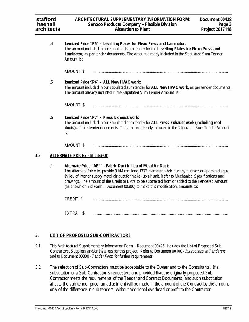
.4 Itemized Price ‘IP5’ - Levelling Plates for Flexo Press and Laminator: The amount included in our stipulated sum tender for the Levelling Plates for Flexo Press and
Laminator, as per tender documents. The amount already included in the Stipulated Sum Tender Amount is:
AMOUNT $ ..................................................................................................................................
.5 Itemized Price ‘IP6’ - ALL New HVAC work: The amount included in our stipulated sum tender for ALL New HVAC work, as per tender documents.
The amount already included in the Stipulated Sum Tender Amount is:
AMOUNT $ ..................................................................................................................................
.6 Itemized Price ‘IP7’ - Press Exhaust work: The amount included in our stipulated sum tender for ALL Press Exhaust work (including roof
ducts), as per tender documents. The amount already included in the Stipulated Sum Tender Amount is:
AMOUNT $ .................................................................................................................................. 4.2 ALTERNATE PRICES - In Lieu-Of:
.1 Alternate Price ‘AP1’ - Fabric Duct in lieu of Metal Air Duct: The Alternate Price to, provide 9144 mm long 1372 diameter fabric duct by ductsox or approved equal
In lieu of interior supply metal air duct for make- up air unit. Refer to Mechanical Specifications and drawings. The amount of the Credit or Extra to be subtracted from or added to the Tendered Amount (as shown on Bid Form – Document 00300) to make this modification, amounts to:
CREDIT $ .................................................................................................................................. EXTRA $ ....................................................................................................................... 5. LIST OF PROPOSED SUB-CONTRACTORS 5.1 This Architectural Supplementary Information Form – Document 00428 includes the List of Proposed Sub-
Contractors, Suppliers and/or Installers for this project. Refer to Document 00100 - Instructions to Tenderers and to Document 00300 - Tender Form for further requirements.
5.2 The selection of Sub-Contractors must be acceptable to the Owner and to the Consultants. If a
substitution of a Sub-Contractor is requested, and provided that the originally-proposed Sub-Contractor meets the requirements of the Tender and Contract Documents, and such substitution affects the sub-tender price, an adjustment will be made in the amount of the Contract by the amount only of the difference in sub-tenders, without additional overhead or profit to the Contractor.
stafford ARCHITECTURAL SUPPLEMENTARY INFORMATION FORM: Document 00428 haensli Sonoco Products Company – Flexible Division Page 4 architects Alteration to Plant Project 2017118
Filename: 00428.Arch.Suppl.Info.Form.2017118.doc 1/23/18
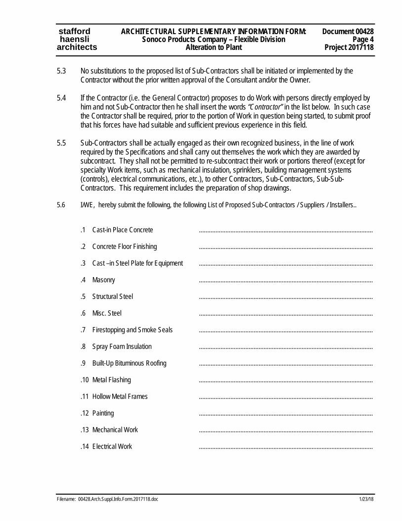
5.3 No substitutions to the proposed list of Sub-Contractors shall be initiated or implemented by the Contractor without the prior written approval of the Consultant and/or the Owner.
5.4 If the Contractor (i.e. the General Contractor) proposes to do Work with persons directly employed by
him and not Sub-Contractor then he shall insert the words “Contractor” in the list below. In such case the Contractor shall be required, prior to the portion of Work in question being started, to submit proof that his forces have had suitable and sufficient previous experience in this field.
5.5 Sub-Contractors shall be actually engaged as their own recognized business, in the line of work
required by the Specifications and shall carry out themselves the work which they are awarded by subcontract. They shall not be permitted to re-subcontract their work or portions thereof (except for specialty Work items, such as mechanical insulation, sprinklers, building management systems (controls), electrical communications, etc.), to other Contractors, Sub-Contractors, Sub-Sub-Contractors. This requirement includes the preparation of shop drawings.
5.6 I/WE, hereby submit the following, the following List of Proposed Sub-Contractors / Suppliers / Installers..
.1 Cast-in Place Concrete ......................................................................................................... .2 Concrete Floor Finishing ......................................................................................................... .3 Cast –in Steel Plate for Equipment ......................................................................................................... .4 Masonry ......................................................................................................... .5 Structural Steel ......................................................................................................... .6 Misc. Steel ......................................................................................................... .7 Firestopping and Smoke Seals ......................................................................................................... .8 Spray Foam Insulation ......................................................................................................... .9 Built-Up Bituminous Roofing .........................................................................................................
.10 Metal Flashing ......................................................................................................... .11 Hollow Metal Frames ......................................................................................................... .12 Painting .........................................................................................................
.13 Mechanical Work .........................................................................................................
.14 Electrical Work .........................................................................................................
stafford ARCHITECTURAL SUPPLEMENTARY INFORMATION FORM: Document 00428 haensli Sonoco Products Company – Flexible Division Page 5 architects Alteration to Plant Project 2017118
Filename: 00428.Arch.Suppl.Info.Form.2017118.doc 1/23/18
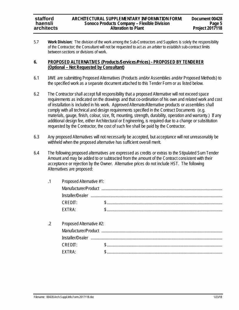
5.7 Work Division: The division of the work among the Sub-Contractors and Suppliers is solely the responsibility of the Contractor; the Consultant will not be requested to act as an arbiter to establish sub-contract limits between sections or divisions of work.
6. PROPOSED ALTERNATIVES (Products/Services/Prices) - PROPOSED BY TENDERER (Optional – Not Requested by Consultant) 6.1 I/WE are submitting Proposed Alternatives (Products and/or Assemblies and/or Proposed Methods) to
the specified work as a separate document attached to this Tender Form or as listed below. 6.2 The Contractor shall accept full responsibility that a proposed Alternative will not exceed space
requirements as indicated on the drawings and that co-ordination of his own and related work and cost of installation is included in his work. Approved Alternate/Alternative products or assemblies shall comply with all technical and design requirements specified in the Contract Documents (e.g. materials, gauge, finish, colour, size, fit, mounting, strength, durability, operation and warranty.) If any additional design fee, either Architectural or Engineering, is required due to a change or substitution requested by the Contractor, the cost of such fee shall be paid by the Contractor.
6.3 Any proposed Alternatives will not necessarily be accepted, but acceptance will not unreasonably be
withheld when the proposed alternative has sufficient overall merit. 6.4 The following proposed alternatives are expressed as credits or extras to the Stipulated Sum Tender
Amount and may be added to or subtracted from the amount of the Contract consistent with their acceptance or rejection by the Owner. Alternative prices do not include HST. The following Alternatives are proposed:
.1 Proposed Alternative #1: Manufacturer/Product ................................................................................................................ Installer/Dealer .......................................................................................................................... CREDIT: $ ........................................................................................................... EXTRA: $ ........................................................................................................... .2 Proposed Alternative #2: Manufacturer/Product ................................................................................................................ Installer/Dealer .......................................................................................................................... CREDIT: $ ........................................................................................................... EXTRA: $ ...........................................................................................................

stafford ARCHITECTURAL SUPPLEMENTARY INFORMATION FORM: Document 00428 haensli Sonoco Products Company – Flexible Division Page 6 architects Alteration to Plant Project 2017118
Filename: 00428.Arch.Suppl.Info.Form.2017118.doc 1/23/18
7. CONFLICT DECLARATIONS AND SIGNATURE .1 I/WE declare that this Document 00428 – Architectural Supplementary Information Form is being
submitted without any connection, knowledge, comparison of figures, or arrangement with any other company, firm or person making a Tender for the same work and is in all respects fair and without collusion or fraud.
.2 We are submitting this Document 00428 - Architectural Supplementary Information Form under
Corporate Seal as a limited company or witnessed as an individual or partnership. ................................................................................................................................................................. Name of Company ................................................................................................................................................................. Address of Company ................................................................................................................................................................. Name and Position of Signator (print clearly) ................................................................................................................................................................. Signature of Authorized Officer of Company ................................................................................................................................................................. Telephone Fax ................................................................................................................................................................. Email ........................................................................... Name of Witness ............................................................................. ........................................................................... Company Seal Signature of Witness
Dated at ................................................ ............... on ................................................... 2018
END OF ARCHITECTURAL SUPPLEMENTARY INFORMATION FORM - 00428

stafford SUPPLEMENTARY CONDITIONS Document 00810 haensli TO CONTRACT DOCUMENT CCDC No. 2, 2008 Page 1 architects Sonoco Products Company– Flexible Division- Alteration to Plant Project 2017118
Filename: 00810.Suppl.Conditions.CCDC2.2017118.doc 1/23/18
SC1 GENERAL
1.1 The General Conditions for Canadian Standard Construction Document, CCDC No. 2, 2008 edition for the renovation construction at/to Sonoco Products Company – Flexible Division- Alteration to Plant, located at 1691 Matheson Blvd., in the City of Mississauga, Ontario are hereby amended, including Articles A-1 through A-8, the Definitions and Part 1 through Part 12 inclusive. These Supplementary Conditions supersede, replace or amend the Contract Document clauses, as the case may be. Supplementary Conditions are indicated in this Document 00810 as "SC 1" (for Supplementary Condition No. 1), "SC 2", etc.
1.2 Throughout the Contract Documents references to the "General Conditions of the Contract"
or "General Conditions" shall include the Supplementary General Conditions listed in this Document 00810. These Supplementary Conditions shall apply to all Work.
1.3 Where any article, paragraph or sub-paragraph in the General Conditions is altered or
supplemented by one of the following paragraphs, the provisions of such article, paragraph or sub-paragraph shall remain in effect and the supplemental provisions shall be considered as added thereto.
1.4 Where any article, paragraph, or sub-paragraph in the General Conditions is voided, replaced
or superseded by any of the following paragraphs, the portions and provisions of the original article, paragraph, or sub-paragraph not so amended, voided or superseded shall remain in effect.
SC2 ARTICLE A-5 - PAYMENT
2.1 Article A-5, Sub-Paragraph 5.3.1: Delete sub-item (1) and (2). Revise the final sentence to read:
“Such interest shall be compounded on a monthly basis. The rate of interest applicable shall be “Bank Prime Rate” plus zero percent, as quoted by the Royal Bank of Canada as of the first day of each applicable month.”
SC3 DEFINITIONS
3.1 Amend Definition 4, “Consultant”, by adding the following to the end of that Definition: “For purposes of the Contract, the terms “Consultant”, “Architect” and “Engineer” shall be considered synonymous.”
3.2 Amend Definition 24, “Value Added Taxes”, by adding the following to the end of that Definition: “For the purposes of this contract, Value Added Taxes shall include the Federal / (Ontario) Provincial Harmonized Sales Tax, commonly referred to as HST.”
Document 00810 SUPPLEMENTARY CONDITIONS stafford Page 2 TO CONTRACT DOCUMENT CCDC No. 2, 2008 haensli Project 2017118 Sonoco Products Company– Flexible Division- Alteration to Plant architects
1/23/18 Filename: 00810.Suppl.Conditions.CCDC2.2017118.doc
3.3 Add a new Definition 27, “Install”, as follows: “Install means install and connect. Install has this meaning whether or not the first letter is capitalized.”
3.4 Add a new Definition 28, “Satisfactory”, as follows:
“Satisfactory means, unless the context provides otherwise, ‘satisfactory to the Owner and the Consultant’. Satisfactory has this meaning whether or not the first letter is capitalized.”
3.5 Add new Definition 30 - Submittals to read:
"Submittals are documents or items required by the Contract Documents to be provided by the Contractor, such as: .1 Shop Drawings, samples, models, mock-ups, to indicate details or characteristics,
before the portion of the Work that they represent can be incorporated into the Work, and
.2 As-Built drawings and manuals to provide instructions to the operation and maintenance of the Work.
SC4 GC 1.1 - CONTRACT DOCUMENTS 4.1 Add new Sub-Paragraphs 1.1.7.5 and 1.1.7.6 to read:
".5 In case of discrepancies, noted materials, procedures and annotations shall take precedence over graphic indications in the Contract Documents.”
".6 Should referenced standards listed in the Specifications conflict with the written
requirements of the Specifications, the Specifications shall govern. Should referenced standards and/or the Specifications conflict with each other, the more stringent requirements shall govern."
4.2 Add new Paragraphs 1.1.11, 1.1.12, 1.1.13 and 1.1.14 to read:
".11 Materials and work specified or indicated on Drawings in accordance with
cross-section indications, abbreviations, legends or symbols identified in the Contract Documents shall be supplied and installed as part of the Work of the Contract.“
“.12 Materials and Work described or identified in the Specifications and not shown on
the Drawings, or that which is shown on the Drawings but not described or identified in the Specifications, shall be provided and completed as if shown or described in both. Related materials and/or preparation work which are not specifically shown on the Contract Documents but are required to perform the Work shown, or are reasonably inferable therefrom as being necessary to complete the Work, shall be provided by the Contractor.”
stafford SUPPLEMENTARY CONDITIONS Document 00810 haensli TO CONTRACT DOCUMENT CCDC No. 2, 2008 Page 3 architects Sonoco Products Company– Flexible Division- Alteration to Plant Project 2017118
Filename: 00810.Suppl.Conditions.CCDC2.2017118.doc 1/23/18
“.13 Items of work which are identified as being supplied and/or performed by a particular trade, but which Work is not shown or specifically identified on the drawings or specifications normally associated with that particular trade are to be included in the Work of the Contract.”
“.14 The organization of Specifications into divisions, sections and articles, and the
arrangement of drawings shall not control the Contractor in dividing the work among Subcontractors or in establishing the extent of the work to be performed by any trade. The Contractor is responsible for all Work required by the Contract regardless of division in the Specifications. Such division shall not obligate the Consultant or Owner to arbitrate to establish limits of responsibility between Contractor and Subcontractor and/or between two or more Subcontractors."
SC5 GC 2.3 - REVIEW AND INSPECTION OF THE WORK 5.1 Revise Paragraph 2.3.2 to read:
“2.3.2 If work is assigned for special tests, inspections, review or approvals in the Contract Documents, or by the Consultant's instructions, or the laws or ordinances of the Place of the Work, the Contractor shall give the Consultant timely notice of when the work will be ready for review. Contractor shall allow a reasonable period for such review to take place. The Contractor shall arrange for and give the Consultant reasonable notice of the date and time of inspections by other authorities."
5.2 Revise Paragraph 2.3.4 to read:
“2.3.4 If the Contractor covers or permits to be covered work that has been designated for special tests, inspections, review, or approvals before such special tests, inspections, review, or approvals are made, given or completed, he shall, if so directed, uncover such work, have the inspections, review or tests satisfactorily completed and make good covering work at the Contractor's expense.”
SC6 GC 2.4 – DEFECTIVE WORK
6.1 Add new subparagraphs 2.4.1.1 and 2.4.1.2 to read:
“2.4.1.1 The Contractor shall rectify, in a manner acceptable to the Owner and the Consultant, all defective work and deficiencies throughout the Work, whether or not they are specifically identified by the Consultant.”
“2.2.1.2 The Contractor shall prioritize the correction of any defective work which, in the sole
discretion of the Owner, adversely affects the day to day operation of the Owner.” SC7 GC 3.1 – CONTROL OF THE WORK
Document 00810 SUPPLEMENTARY CONDITIONS stafford Page 4 TO CONTRACT DOCUMENT CCDC No. 2, 2008 haensli Project 2017118 Sonoco Products Company– Flexible Division- Alteration to Plant architects
1/23/18 Filename: 00810.Suppl.Conditions.CCDC2.2017118.doc
7.1 Add new paragraph 3.1.3 to read:
“3.1.3 Prior to commencing individual procurement, fabrication and construction activities, the Contractor shall verify, at the Place of the Work, all relevant measurements and levels necessary for proper and complete fabrication, assembly and installation of the Work and shall further carefully compare such field measurements and conditions with the requirements of the Contract Documents. Where dimensions are not included or contradictions exist, or exact locations are not apparent, the Contractor shall immediately notify the Consultant in writing and obtain written instructions from the Consultant before proceeding with any part of the affected work.”
SC8 GC 3.4 – DOCUMENT REVIEW
8.1 Delete paragraph 3.4.1 in its entirety and substitute new paragraph 3.4.1 to read:
“3.4.1 The Contractor shall carefully review the Contract Documents and shall report promptly to the Consultant any error, inconsistency or omission which the Contractor may discover. Such review by the Contractor shall comply with the standard of care described in paragraph 3.14.1 of the Contract. Except for its obligation to make such review and report the result, the Contractor does not assume any responsibility to the Owner or to the Consultant for the accuracy of the Contract Documents. The Contractor shall not be liable for damage or costs resulting from such errors, inconsistencies or omissions in the Contract Documents, which the Contractor could not reasonably have discovered. If the Contractor does discover any error, inconsistency or omission in the Contract Documents, the Contractor shall not proceed with the work affected until the Contractor has received corrected or missing information from the Consultant.”
SC9 GC 3.7 - SUBCONTRACTORS AND SUPPLIERS
9.1 Add the following new sentence to the end of paragraph 3.7.4: “No adjustment to the Contract Price will be made in the event that the original Subcontractor
or Supplier (or Supplier’s product) proposed was not acceptable under the specified terms and conditions of the Contract Documents (such as acceptable Subcontractors listed, acceptable products specified or similar condition).”
SC10 GC 3.11 - USE OF THE WORK 10.1 Add new Paragraphs 3.11.3 and 3.11.4 to read:
"3.11.3 The Owner shall have the right to enter and occupy the building in whole or in part for the purpose of placing fittings and equipment, or for other use before completion of the Contract if, in the opinion of the Consultant, such entry and

stafford SUPPLEMENTARY CONDITIONS Document 00810 haensli TO CONTRACT DOCUMENT CCDC No. 2, 2008 Page 5 architects Sonoco Products Company– Flexible Division- Alteration to Plant Project 2017118
Filename: 00810.Suppl.Conditions.CCDC2.2017118.doc 1/23/18
occupation does not prevent or interfere with the Contractor in the performance of the completion of the Work of the Contract within the time specified.”
“3.11.4 Such entry or occupation by the Owner shall not be considered as acceptance of
the work, or in any way relieve the Contractor from his responsibility to complete the Contract."
SC11 GC 3.14 – PERFORMANCE BY THE CONTRACTOR 11.1 Add new General Condition 3.14 – PERFORMANCE BY THE CONTRACTOR, to read:
“3.14.1 In performing its services and obligations under the Contract, the Contractor shall exercise a standard of care, skill and diligence that would normally be provided by an experienced and prudent contractor supplying similar services on similar projects. The Contractor acknowledges and agrees that throughout the Contract, the Contractor’s obligations, duties and responsibilities shall be interpreted in accordance with this standard. The Contractor shall exercise the same standard of due care and diligence in respect of any Products, personnel, or procedures which it may recommend to the Owner.”
“3.14.2 The Contractor further represents, covenants and warrants to the Owner that:
.1 The personnel it assigns to the Project are appropriately experienced;
.2 It has sufficient quantity of qualified and competent personnel to replace its designated supervisor and project manager, subject to the Owner’s approval, in the event of death, incapacity, removal or resignation.”
SC12 GC 4.1 – CASH ALLOWANCES
12.1 Delete and replace the last sentence in paragraph 4.1.4 to read: “Multiple cash allowances may, at the discretion of the Owner and the Consultant, be
combined for the purpose of calculating the foregoing.” 12.2 Delete and replace paragraph 4.1.5 to read: “The net amount of any unexpended cash allowances, after providing for any reallocations as
contemplated in paragraph 4.1.4, shall be deducted from the Contract Price by Change Order.”
12.3 Add new paragraph 4.1.8 to read:
“4.1.8 The Owner reserves the right to call, or to have the Contractor call, for competitive bids for portions of the Work, to be paid for from cash allowances.”
SC13 GC 4.2 – CONTINGENCY ALLOWANCE
13.1 Add new paragraph 4.2.5 to read:
Document 00810 SUPPLEMENTARY CONDITIONS stafford Page 6 TO CONTRACT DOCUMENT CCDC No. 2, 2008 haensli Project 2017118 Sonoco Products Company– Flexible Division- Alteration to Plant architects
1/23/18 Filename: 00810.Suppl.Conditions.CCDC2.2017118.doc
“Mark-ups for work paid for by Contingency Allowance shall not exceed those designated in GC 6.2 – CHANGE ORDER, including any Supplementary Conditions affecting GC 6.2.”
SC14 GC 5.2 - APPLICATIONS FOR PROGRESS PAYMENT
14.1 Refer to Paragraph 5.2.3: Change period at end of paragraph to a comma and add the following:
"...where such products have been incorporated into the work or properly stored, secured and quantified as per paragraph 5.2.7 and as approved by the Consultant and the Owner."
14.2 Revise the time period listed in Paragraph 5.3.2 to ten (10) calendar days (from 5 days).
14.3 Add new Clause 5.2.8 to read: "5.2.8.1. The Contractor shall submit with each application for payment after the first:
.1 A Statutory Declaration stating that all accounts for wages, materials, Subcontractors and services have been paid to the end of the period covered by the preceding applications and that none of the material on the site has been purchased under a conditional sale or hire-purchase agreement,
.2 A valid and current Workplace Safety and Insurance Board (WSIB) clearance certificate.”
“5.2.8.2 With the application for release of holdback, the Contractor shall submit:
.1 All specified written guarantees, bonds, records, certificates and statements,
.2 A Statutory Declaration stating that all accounts in connection with the Contract have been paid in full,
.3 Evidence of compliance with the Construction Lien Act, regarding notifications, publications, advertisements, etc.,
.4 A valid and current Workplace Safety and Insurance Board (WSIB) clearance certificate.”
SC15 GC 5.4 – SUBSTANTIAL PERFORMANCE OF THE WORK
15.1 Add new paragraphs 5.4.4, 5.4.5, 5.4.6 and 5.4.7 to read: “5.4.4 The Consultant shall prepare and issue a Deficiency List, outlining all observed
items of outstanding and/or defective work which exist as of the date of Substantial Performance of the Work, provided that:
.1 The list specified in Paragraph 5.4.1 has been received, and .2 Substantial Performance of the Work has been certified in accordance with
applicable Lien legislation, and in accordance with Paragraph 5.4.2.
"5.4.5 Contractor shall provide an itemized schedule for completion of outstanding work. When outstanding work is complete or nearly completed (minimum 85% of listed
stafford SUPPLEMENTARY CONDITIONS Document 00810 haensli TO CONTRACT DOCUMENT CCDC No. 2, 2008 Page 7 architects Sonoco Products Company– Flexible Division- Alteration to Plant Project 2017118
Filename: 00810.Suppl.Conditions.CCDC2.2017118.doc 1/23/18
items), the Contractor shall submit a marked-up Deficiency List to the Consultant, indicating which items have been completed to that date and which items are not yet complete. Consultant will review the work in a timely manner and will issue a revised Deficiency List, showing items of work still outstanding.”
“5.4.6 The procedure outlined in Paragraphs 5.4.5 will be repeated (correction of work,
marked-up list submitted, re-review of work by the Consultant, re-issue of Deficiency List by the Consultant).”
“5.4.7 At the completion of the procedures specified in Paragraph 5.4.6 or at the expiry
of the deficiency correction period (whichever occurs first), the Consultant may recommend that the Owner undertake alternative measures to achieve completion and/or correction of outstanding and/or defective work. Should the Owner undertake these alternative measures, the costs of such measures shall be deducted from the monies remaining to be paid to the Contractor. Alternative measures for work completion and/or correction shall not adversely affect any warranties/guarantees in place on the Project.”
SC16 GC 6.1 – OWNERS RIGHT TO MAKE CHANGES 16.1 Add new Paragraphs 6.1.3 and 6.1.4 to read:
"6.1.3 Contractor shall inform Surety Company or Companies who have issued Performance Bonds for this Contract, of any changes to Contract, so that validity of coverage of such bonds is at no time impaired. If any change to Contract requirements adjustments of the Bonds, the Contractor shall initiate and pay for such adjustments. Costs of adjustments to bonding coverage shall be included as part of the Contractor’s overhead percentage mark-up allowed for changes.”
“6.1.4 The Contractor shall advise the Consultant if the schedule is affected by any
change and obtain authorization from the Consultant before proceeding with related work which may affect contemplated changes. The Contractor shall advise the Consultant of the affect on the overall schedule, if any, due to changes required by a change notice."
SC17 GC 6.2 - CHANGE ORDER 17.1 Amend paragraph 6.2.1 by adding the following sentence to the end of that paragraph:
“Such adjustments and method of adjustment must be submitted by the Contractor to the Consultant in sufficient time to prevent interruption of the orderly process of construction and, in any event, no later than ten (10) days from the Contractor’s receipt of the proposed change in the Work.”
17.2 Add new paragraphs 6.2.3 and 6.2.4 to read:

Document 00810 SUPPLEMENTARY CONDITIONS stafford Page 8 TO CONTRACT DOCUMENT CCDC No. 2, 2008 haensli Project 2017118 Sonoco Products Company– Flexible Division- Alteration to Plant architects
1/23/18 Filename: 00810.Suppl.Conditions.CCDC2.2017118.doc
“6.2.3 The value of a change in the Work shall be determined in one or more of the following methods as directed by the Owner: .1 by estimate and acceptance of a lump sum; .2 by unit prices established in the Contract Documents or subsequently agreed
upon. Unit prices shall include overhead, profit, and other reasonable charges of the Contractor and shall be the total cost to the Owner. Adjustment to the Contract Price shall be based on a net quantity difference from the original quantity;
.3 by the amount, net of all credits, of time, materials and Products expended: (1) by a Subcontractor applying the labour rates set out in the Contract
Documents together with the actual costs, without mark-up, of materials and Products utilized in the change, plus the Subcontractor's mark-up disclosed in the table below which applies to material and Product costs only;
(2) by the Contractor applying the labour rates set out in the Contract Documents together with the actual costs, without mark-up, of materials and Products plus the mark-up disclosed in the table below which applies to material and Product costs only;
(3) the Contractor shall also be entitled to the Contractor mark-up disclosed in the table below on the value of Subcontractor work.
Change in the Contract Price Subcontractor Mark-Up (%)
on work provided by the Subcontractor OR Contractor Mark-Up
on work provided by the Contractor (includes overhead and profit)
Contractor Mark-Up (%) on Subcontractor work
(includes overhead and profit)
$0 to no more than $25,000 10% 5%
$0 to no more than $50,000 9% 5%
$0 to in excess of $50,000 7% 4%
Interpretive Note: The mark-ups disclosed in the above table are flat, not graduated. For example, a change performed by a Subcontractor valued at $35,000 attracts a mark-up of 8% for the Subcontractor and 5% for the Contractor. The table is not intended to provide one set of mark-ups for the first $25,000 of the change and a lower set of mark-ups for the balance. 6.2.4 The mark-ups described in paragraph 6.2.3.3 are intended to cover all general
expenses and overhead costs incurred by the Contractor in relation to the change. For greater certainty, the following items are covered by and included in the mark-ups: additional bonding and insurance costs, supervision, project management, general account items, small tools, estimating, safety, preparation of record drawings, coordination and administration and warranty costs, and general clean-up and disposal costs necessary to perform the change in the Work.”
stafford SUPPLEMENTARY CONDITIONS Document 00810 haensli TO CONTRACT DOCUMENT CCDC No. 2, 2008 Page 9 architects Sonoco Products Company– Flexible Division- Alteration to Plant Project 2017118
Filename: 00810.Suppl.Conditions.CCDC2.2017118.doc 1/23/18
SC18 GC 6.3 - CHANGE DIRECTIVE
18.1 Delete paragraphs 6.3.7.13 and 6.3.7.15 in their entirety.
18.2 Add a new paragraph 6.3.14 as follows: “6.3.14 Without limitation, the following shall not form part of the cost of performing the
work attributable to the Change Directive, and shall not be recoverable by the Contractor: .1 head office salaries and benefits and all other overhead or general
expenses, except only for the salaries, wages and benefits of personnel described in paragraph 6.3.7.1 and the contributions, assessments or taxes referred to in paragraph 6.3.7.2;
.2 capital expenses and interest on capital;
.3 general cleanup, except where the performance of the work attributable to the Change Directive causes specific additional cleanup requirements;
.4 wages paid for field supervision of Subcontractors;
.5 wages, salaries, rentals or other expenses that exceed the rates that are standard in the locality of the Place of the Work or that are otherwise deemed unreasonable by the Consultant;
.6 any costs or expenses attributable to the negligence, improper work, deficiencies, or breaches of contract by the Contractor or any Subcontractor; and
.7 any cost of quality assurance, such as inspection and testing services, or charges levied by authorities, and any legal fees unless any such costs or fees are pre-approved in writing by the Owner.”
18.3 Add new paragraph 6.3.14 to read: “Mark-ups for work governed by a Change Directive shall not exceed those designated in GC
6.2 – CHANGE ORDER, including any Supplementary Conditions affecting GC 6.2.” SC19 GC 6.4 – CONCEALED OR UNKNOWN CONDITIONS 19.1 Add new paragraphs 6.4.4 and 6.4.5.to read:
“6.4.4 Should the conditions at the place of the Work, as referenced in sentence 6.4.1, be determined to have been disturbed at the location of the concealed or unknown condition(s) in question to such an extent that accurate and detailed evaluation and/or measurement of any required additional Work and/or materials is not possible, the Consultant shall so state. In this case the Consultant shall propose a method for cost determination which, in the opinion of the Consultant, is fair and reasonable to both the Owner and the Contractor, based upon the general level of related and/or applicable information available in the Contract Documents and on the jobsite.”
Document 00810 SUPPLEMENTARY CONDITIONS stafford Page 10 TO CONTRACT DOCUMENT CCDC No. 2, 2008 haensli Project 2017118 Sonoco Products Company– Flexible Division- Alteration to Plant architects
1/23/18 Filename: 00810.Suppl.Conditions.CCDC2.2017118.doc
“6.4.5 The Contractor confirms that, prior to bidding the Project, it carefully investigated the Place of the Work and applied to that investigation the degree of care and skill described in paragraph 3.14.1, given the amount of time provided between the issue of the bid documents and the actual closing of the bids, the degree of access provided to the Contractor prior to submission of the bid, and the sufficiency and completeness of the information provided by the Owner. The Contractor is not entitled to compensation or to an extension of the Contract Time for conditions which could reasonably have been ascertained by the Contractor by such careful investigation undertaken prior to the submission of the bid.”
SC20 GC 6.5 – DELAYS
20.1 Add new paragraph 6.5.6 to read: “6.5.6 If the Contractor is delayed in the performance of the Work by an act or omission of
the Contractor or anyone employed or engaged by the Contractor, directly or indirectly, or by any cause within the Contractor’s control, then: .1 the Contract Time shall be extended for such reasonable time as the
Consultant may decide, in consultation with the Contractor and the Owner, .2 the Owner shall be reimbursed by the Contractor for all reasonable costs
incurred by the Owner as a result of such delay, .3 such costs referred to in .2 above shall include the cost of the Consultant’s
services during the period by which the Contract Time is extended and the time expended in determining the validity and length of the extension to the Contract Time.”
SC21 GC 11.1 – INSURANCE 21.1 Refer to Paragraph 11.1.1.1, second line: Change the insurance amount to Five Million ($5,000,000.00) (from $2,000,000.00) on
Comprehensive General Liability and Two Million ($2,000,000.00) on accident and all-risk contractor property and equipment policy.
Sonoco Products Company - Flexible Division must be named as additional insured on ALL insurance policies
SC22 GC 12.3 - WARRANTY 22.1 Add the following new sentences to the end of paragraph 12.3.1: "The length of warranty specified in this Paragraph 12.3.1 is general in coverage and
minimum in period. Specific longer time limits for warranties/guarantees for certain work and materials are incorporated in the Specifications and shall govern. In no case shall any clause in the Specifications reduce the warranty/guaranty period for any item or section of work to a period shorter than the basic overall warranty/guaranty period for the Project.”
END OF DOCUMENT 00810

stafford 01001 haensli SUMMARY OF WORK & GENERAL REQUIREMENTS Page 1 architects Project 2017118
Filename: 01001.SummaryWork.2017118.doc 1/23/2018
1 General 1.1 REQUIREMENTS INCLUDED .1 Requirements Included .2 Related Requirements .3 Title and description of Work .4 Work Covered by Contract Documents .5 Contract Method .6 Contract Documents .7 Work by Others .8 Pre-ordered Products & Pre-tendered Work .9 Owner Furnished Items .10 Future Work .11 Work Division and Sequence .12 Contractor Use of Premises .13 Construction Project Schedule .14 Tendering Conditions Which Remain Applicable Throughout Construction Period .15 Ontario Building Code Information .16 Bylaws, Permits and Approvals .17 Special Site Conditions 1.2 RELATED REQUIREMENTS .1 Document 00100: Instructions to Bidders .2 Document 00300: Form of Tender .3 Document 01010: General Requirements .4 CCDC2 Document 2008 .5 Document 00810 Supplementary Conditions 1.3 TITLE AND DESCRIPTION OF WORK .1 This project is to be known as:
SONOCO PRODUCTS COMPANY – FLEXIBLE DIVISION ALTERATIONS TO EXISTING PLANT
at 1691 Matheson Boulevard East, Mississauga, Ontario
.2 Work of this Contract comprises of alterations construction, to Sonoco Products Company –
Flexible Division, located at 1691 Matheson Bouldevard, Mississauga, Ontario. Sonoco Products Company – Flexible Division will be the Owner of record with respect to the construction Contract. The construction contract (generally) includes the following work:
01001 stafford Page 2 SUMMARY OF WORK & GENERAL REQUIREMENTS haensli Project 2017118 architects
1/23/2018 Filename: 01001.SummaryWork.2017118.doc
.2 WORK BY GENERAL CONTRACTOR (INCLUDED IN LUMP SUM PRICE): .1 General Conditions: General project construction setup, control and co-ordination.
General Contractor shall provide the following: .1 Superintendent & Labourers: A full time Superintendent on the jobsite.
General Contractor will also be expected to provide general labourers and/or carpenters to perform miscellaneous work, as is normal for construction projects of this size.
.2 Bonding: It is required that the General Contractor provide a 50% Performance Bond and a 50% Labour and Material Payment Bond for the work of this project. Bond shall remain in effect until the expiry of the standard one (1) year warranty period (via bonding warranty work provisions).
.3 Safety: General Contractor shall be responsible for ensuring that all trades present on the site adhere to Sonoco Product Company’s safety policy, any access and/or security policies set forth by Sonoco Products Company, restricted smoking areas, providing a minimum of 30 minutes dedicated fire watch following any and all welding, flame cutting or any other construction operations which produce flames, sparks or significant heat (exception to this last item is that the structural steel contractor will provide the required fire watch for their own work).
.4 Scheduling: General Contractor will be responsible for scheduling of work of the various subtrades to ensure that all work gets performed in a timely manner, with maximum time allowing more than one trade to work simultaneously and minimum time gaps between sequential trades/operations.
.5 Disposal & Hoarding: It is assumed that the General Contractor will provide general clean-up, disposal, hoarding and other construction services for all trades (unless one or more of these services are contracted-out to specific sub-trades by the General Contractor).
.2 Concrete Cutting: Concrete cutting (including removal and disposal of existing
concrete) at existing interior concrete floor slab at area of new printing press & Laminator base.
.3 Excavation for Press & Laminator Bases: Machine and hand excavation at slab
removal area to volume required for installation of new concrete press and Laminator bases plus additional excavation area as required to allow installation of formwork for pouring of new press base, including removal and disposal of existing (surplus) excavated materials.
.4 Formwork/Reinforcing for Press & Laminator Bases: Formwork and steel
reinforcing (supply and install) at area/volume of new concrete press base.
stafford 01001 haensli SUMMARY OF WORK & GENERAL REQUIREMENTS Page 3 architects Project 2017118
Filename: 01001.SummaryWork.2017118.doc 1/23/2018
.5 Concrete Press & Laminator Bases: Pour, vibrate, cure and finish new reinforced concrete printing press base – to size and depth shown on drawings. Top surface of base shall be finished to “super flat” tolerances and shall receive a smooth, steel trowelled finish. Concrete shall be wet cured to minimize shrinkage. Final concrete top surface shall be treated with curing compound during concrete cure and finally cleaned and sealed just prior to Owner take-over.
.6 Pour-Back Floor Slab: Following pouring of new printing press & Laminator bases
and removal of formwork, backfill (using Granular ‘B’) to underside of floor slab, fully compacting backfill material in 150 mm (6 in.) lifts. Pour and finish new 150 mm (6 in.) thick concrete floor slab at area surrounding the new concrete press base. Dowel new slab into edge of existing floor slab at 600 mm o.c. (do not dowel into press base). Include 6x6 wire mesh slab reinforcing in concrete floor slab. Finish top surface of floor slab to a smooth steel trowelled finish, maintaining maximum flatness while “feathering” the top surface evenly from existing top-of-slab levels to the new top-of-press/laminator-base levels, avoiding all abrupt changes in height and ensuring perfectly even finished surface transitions at both existing surfaces.
.7 Drilling of concrete base and installation of machinery anchors (Levelling plates) in
place.
.8 Built-Up Roofing: Supply and install (via roofing subtrade) new built-up roofing system, flexible flashing etc., at base of new RTU roof area.
.9 Electrical Power Provisions: Any electrical power provisions which the Owner
(through other contractors) will not be providing, will be provided under this contract’s work. These items (as or if applicable) will be shown on electrical drawings.
.10 New Masonry Wall/Door/bollards: At conclusion of construction period (just after
the arrival of new printing press and Laminator equipment in June), Remove the existing O/H shutter, Supply and Install new masonry wall, door, bollards and all associated work.
.11 Supply and installation of new rooftop HVAC mechanical unit next to existing RTU. Including support curb, power connections, gas connection, ductwork to new printing
press machinery, controls, etc. .12 Supply & Install All Exhaust flues, ducts, on roof/supports, connection to existing
oxodizer etc… associated with the Flexo Press. .4 WORK BY OTHER CONTRACTORS (Co-ordination of These Contractors by Owner or
Others – Not by General Contractor): .1 Supply, general setup and connection of new printing press machinery.
01001 stafford Page 4 SUMMARY OF WORK & GENERAL REQUIREMENTS haensli Project 2017118 architects
1/23/2018 Filename: 01001.SummaryWork.2017118.doc
.2 Sprinklers Work: Affected Sprinkler work.
.3 Supply, mounting, routing and connection of power, gas, compressed air, chilled
water utilities and all operational controls to the new printing press and laminator equipment.
1.4 WORK COVERED BY CONTRACT DOCUMENTS .1 The work covered by (included in) the Contract Documents includes the complete
construction of the new building and limited re-development/finishing of the site as indicated on the drawings and in the specifications, starting from the existing site as it exists at the time of Tender Close, and including structural, architectural, mechanical, electrical, controls, finishes, sitework, landscaping, etc.
.2 Payments for permits, fees, bonds, insurance, etc. are documented throughout the Contract
Documents as to which of these are to be included in the Stipulated Price Contract Amount and which are to be paid by the Owner directly, or by others.
.3 Work not covered by (included in) the Contract Documents includes those items marked as
Not In Contract (NIC), furnishings not shown, Owners' equipment not shown, etc. .4 Products Supplied by the Owner:
.1 The Owner, for incorporation into Work of this Contract will supply products indicated accordingly either on the drawings or in the specifications.
.2 The Owner will provide manufacturer's installation instructions for each such product as available.
.3 The Contractor's duties with respect to products supplied by the Owner, are, but not necessarily limited to, the following: .1 Unload and handle at site. .2 Promptly inspect delivered products and give written report to the Consultant
on condition of all items received. .3 Pay demurrage charges. .4 Temporarily store products in secure and suitable storage. .5 Install, connect and finish products as specified. .6 Remove packaging material from site and clean products.
.4 The Contractor shall co-operate fully with any and all Owner commissioned Contractors.
1.5 CONTRACT METHOD .1 Construct the Work under a single lump sum fixed price construction contract.
stafford 01001 haensli SUMMARY OF WORK & GENERAL REQUIREMENTS Page 5 architects Project 2017118
Filename: 01001.SummaryWork.2017118.doc 1/23/2018
.2 The Construction Contract Document (form) shall be standard stipulated price contract CCDC2 - 2008 Stipulated Price Contract. A copy of the standard contract document is not included in the printed specifications book, but the Consultant can provide a sample of this document for reference purposes.
.3 Sub-Contract Awards:
.1 The Contractor shall, on notice of award of the Contract, obtain the Consultants'
approval of a complete list of all persons or firms to which the Contractor proposes to sub-contract any part of the Work, the scope of the sub-contracts being assigned, and the amount of each sub-contract.
.2 The Contractor shall provide to the Consultant a financial breakdown showing all
divisions of the Work amounting to the full sum of the Contract Price. Electrical and Mechanical sub-contracts shall be further broken down as requested by the Consultants.
.4 Relationship Among and Between Trades:
.1 The Contractor is responsible for co-ordinating all trades. The Contractor is solely responsible for determining the lines of demarcation between Contractor and/or each of the Sub-Contractors.
.2 Neither the Consultant nor the Owner assumes any responsibility for any such
determination or for any dispute arising concerning it. No extras will be considered due to any such dispute concerning either labour or materials.
1.6 CONTRACT DOCUMENTS
.1 The Contract Specifications have been generally divided into trade sections for the purpose of ready reference. The division of the specifications and the location of work items (supply and/or install) does not stipulate the Division of Work within the overall Contract. Descriptions of items are (generally) arranged in approximate accordance with the Consultants’ current understanding of subtrade divisions and scope of work for similar projects. As stated elsewhere in the Contract Documents, the Contractor is solely responsible for the division and assignment of the Work.
.2 Specifications and drawings form an integral part of the Contract Documents. Any subject or
item listed and/or shown by one, but which is omitted from OR which is mentioned OR which is reasonably implied in the other, shall be considered as properly and sufficiently specified / detailed and will be part of the Work.
.3 The Contractor and Sub-Contractors shall examine carefully all drawings and specifications to
inform themselves fully of all conditions and limitations pertaining to the Work of the Contract. 1.7 WORK BY OTHERS
01001 stafford Page 6 SUMMARY OF WORK & GENERAL REQUIREMENTS haensli Project 2017118 architects
1/23/2018 Filename: 01001.SummaryWork.2017118.doc
.1 Work by Others shall include the Work identified as “Phase 2 Work” on the drawings and in
the specifications. This middle phase of work will be undertaken by Enersource Hydro Mississauga (directly, or with the assistance of separately-contracted Subtrades). It is generally the intent that the General Contractor will have left the site prior to the “Phase 2 Work” commencing. Following completion of the “Phase 2 Work”, the General Contractor will return to the site to perform the “Phase 3 Work”.
.2 Work by Others shall include the provision of loose equipment and/or furnishings; this work
will be tendered separately by the Owner. .3 Work by Others shall include the supply and installation (unless installation is indicated to be
included in the Contract) of miscellaneous equipment which is either indicated as "NIC" on the Contract Documents or is not known or indicated at this time.
1.8 PRE-ORDERED PRODUCTS AND PRE-TENDERED WORK .1 No products, assemblies or materials shown on the Contract Documents have been pre-
ordered or pre-tendered. 1.9 OWNER FURNISHED ITEMS .1 Owner furnished items shall be limited to those items indicated on the drawings and
specifications and/or to those items listed as Not In Contract (NIC) on the Contract Documents and to other items not known or indicated at this time, except as listed below.
1.10 FUTURE WORK .1 No Future Work is anticipated for this project. 1.11 WORK DIVISION AND SEQUENCE .1 The Contractor shall be fully responsible for work division and work sequence. The
Contractor shall be fully responsible for the overall project progress schedule and meeting of completion dates.
.2 The Contractor shall follow and adhere to the requirements and restrictions of the Contract
Documents with respect to changes and/or proposed changes in products, subtrades, superintendent, etc. It shall not be considered to be a valid excuse for failure to maintain or meet construction schedule deadlines that the Consultant and/or Owner has refused to accept a substitution or change proposed by the Contractor. When valid reasons (which are consistent with the intent of the Contract Documents and which preserve/maintain the best interests of the Owner) are submitted along with the proposed change, the Consultant and/or Owner will not unreasonably withhold approvals for substitutions and/or changes.

stafford 01001 haensli SUMMARY OF WORK & GENERAL REQUIREMENTS Page 7 architects Project 2017118
Filename: 01001.SummaryWork.2017118.doc 1/23/2018
.3 The Consultant and the Owner will co-operate with the efforts of the Contractor to divide the
work and to achieve the required overall project progress but will not direct the work or impose undue restrictions upon the Contractor as to how or when each component of the work is performed.
.4 The Contractor and all Sub-Contractors shall co-operate and co-ordinate their work for the
proper completion of the Work, including co-ordination of delivery dates and commencement of Sub-Contractor’s Work.
.5 The responsibility for all Work, including temporary structures, shoring and erection shall at all
time rest with the Contractor (and, by extension, the Sub-Contractors). The Consultant will review construction methods and shop drawings for arrangements only. The method of obtaining the results contemplated by the Contract Documents shall be determined by the Contractor.
.6 The undertaking of periodic site review by the Consultant or Owner Representative shall not
be construed as supervision of actual construction, nor make them responsible for providing a safe place for Work, visit, use, access, travel, or occupancy of the Consultant’s or Owner’s employees or agents.
.7 The Contractor shall be fully responsible for co-ordinating and expediting the Work of all Sub-
Contractors and shall employ the necessary and qualified personnel to provide the required quality of labour and materials and to prevent delays in the progress of the project. Each Sub-Contractor shall be afforded all reasonable opportunities for the installation of the Sub-Contractor’s own Work and for the storage and handling of required materials.
.8 Overtime: .1 The Contractor shall include in the Contract Price, all costs for overtime Work which
may be necessary to complete the various portions of the Work, in accordance with the Completion Dates specified in Document 00300 – Tender Form.
.2 The Owner shall not entertain requests for any payments in connection with overtime Work that may be required by the Contractor, or any of the Contractor’s Sub-Contractors in order to comply with the above referenced dates.
.3 Both the Contractor and Sub-Contractors, are cautioned that they should not submit bids, if they are unsure of their ability to comply with the stated construction and/or occupancy schedule and requirements, if they are unsure of their ability to provide overtime Work if and as necessary.
1.12 CONTRACTOR USE OF PREMISES & SPECIAL CONDITIONS .1 The Owner has contracted to take delivery of new printing press & Laminator equipment in
June 1, 2018. The intent of this contract is to have the new concrete press bases to be poured as early as schedule will permit.
01001 stafford Page 8 SUMMARY OF WORK & GENERAL REQUIREMENTS haensli Project 2017118 architects
1/23/2018 Filename: 01001.SummaryWork.2017118.doc
.2 The existing Sonoco Products Company plant in Mississauga produces finished packaging materials for food products (candy, cookies, etc.). As such, operations and internal safety / cleanliness / dust and dirt restrictions are governed by the food products authorities. All relevent restrictions and requirements within the building must be adhered to during the construction period – these will be made known to the contractor(s) during the construction process.
.3 Sonoco Products Company is extremely safety conscious, and has a comprehansive,
mandatory safety plan for all operations ocurring within their premises (whether by their own emplyees or by others). Contractor(s) are required to follow the required safety procedures as set forth by Sonoco Products Company, in addition to those set forth by construction safety authorities. Some special requirements which have been highlighted by the Owner to date include:
.1 All persons working within the plant and warehouse spaces must wear safety shoes, eye protection (safety glasses) and ear plugs. No jewlery to be worn.
.2 All ladders used in or on the building (including for construction purposes) must be non-conductive (i.e. fiberglass). Aluminum ladders are not permitted.
.3 Risk of fire is a serious threat to plants such as the one in question. A designated “Fire Watch” person is required to stand watch at all instances of welding, grinding and any other operations which produce fire, flame, glowing metal, sparks or similar (possibly combustible) conditions for a period of not less than 30 minutes following completion of such operations. Sonoco personnel must then be notified, so that Sonoco may then take over the Fire Watch procedures for an extended period of time (sometimes up to 24 hours).
.4 Contractor shall limit the use of the premises to those directly related to performance of The
Work, for storage, and for access, and shall allow for, as part of the normal work of the Contract, the following:
.1 Owner occupancy following the date of Substantial Performance. .2 Work by Other Contractors as required by the Owner or as required for completion of
the work of this Contract. .3 Public usage or access by Consultant, Owner, Municipal Authorities, etc. for review,
inspection or approval purposes. .5 Assume full responsibility for protection and safekeeping of any products, materials,
equipment stored within the building or on the site under this Contract. .6 Obtain and pay for use of additional storage or work areas needed for operations under this
Contract. .7 Contractor shall modify and/or limit the use of the premises for Work, for storage, and for
access if so requested in writing by the Owner (provided that it is determined by the Consultant that the request is reasonable) for the following purposes:
stafford 01001 haensli SUMMARY OF WORK & GENERAL REQUIREMENTS Page 9 architects Project 2017118
Filename: 01001.SummaryWork.2017118.doc 1/23/2018
.1 Partial Owner occupancy prior to the date of Substantial Performance (throughout the construction period).
1.13 CONSTRUCTION PROJECT SCHEDULE
.1 At the commencement of construction a schedule of construction and completion will be prepared and submitted by the Contractor. This schedule will indicate the anticipated date of Substantial Performance for each section of the Work. Once accepted by the Owner, this schedule will become the official project schedule and completion will be expected based upon that schedule. Should the Contractor fall behind the construction progress required to meet the agreed completion date, he will be expected to make up the lost time through overtime, additional shifts, etc.
1.14 TENDERING CONDITIONS WHICH REMAIN APPLICABLE THROUGHOUT THE CONSTRUCTION
PERIOD .1 Performance Bond / Labour and Material Payment Bond - General Contractor and
Mechanical and Electrical Subtrade Contractors
.1 The General Contractor Tenderers shall furnish with their tender an Agreement to Bond for a 100% Performance Bond and a 100% Labour and Material Payment Bond issued by a guarantee company/bonding company which is satisfactory to the Owner, guaranteeing the faithful performance of the work, including corrections after final payment. The Performance Bond and Labour and Material Payment Bond shall be delivered to the Owner contemporaneously with the delivery of the executed Contract. The premium on the Bonds shall be paid for by the Contractor.
.2 The Owner has established a list of permissible General Contractor bidders. These
bidders will be invited to bid the Work of this contract – only those who respond affirmatively will be permitted to bid the Work.
.2 Taxes Included in Tender Amounts
.1 Tender amounts shall include all customs fees, duties, freight, excise taxes, currency exchange and other charges.
.2 The Federal/Provincial Harmonized Sales Tax (HST) is applicable to the work of this
Contract and it shall be excluded from the Stipulated Sum Tender Amount. Include all other taxes and duties in effect and known to come into effect during the construction period for this project as part of the Stipulated Sum Tender amount.
.3 Construction Related Fees, Permits, Building Permit
01001 stafford Page 10 SUMMARY OF WORK & GENERAL REQUIREMENTS haensli Project 2017118 architects
1/23/2018 Filename: 01001.SummaryWork.2017118.doc
.1 General Contractor to apply for and pay all other permit charges, fees, deposits, etc.): The following are the fees, deposits, etc. known by the Owner at this time which will require payment by the Contractor (except as specifically noted below for each item). These fees/permits shall include (as applicable to this project and/or the local Municipality), but not be limited to: (Where amounts are not known, the municipal department to contact is listed)
.1 Securities for Erosion & Sediment Control Permit & Fee- (Amount not known -
contact City of Mississauga, Engineering & Works)
.2 Road Occupany & Access Permit with 48hours prior to contraction (Amount not known - contact City of Mississauga, Engineering & Works)
Please note that the above amounts ARE NOT included in the project Cash Allowance but are to be included in the Stipulated Sum Tender Amount. .2 Municipal Building Permit has been applied for by the Consultant on behalf of the
Owner. The Contractor shall co-operate fully with the Consultants' efforts to achieve approval and issuance of the building permit. The Owner will directly pay for the cost of the Building Permit Fee to the local Municipality. The Contractor will, therefore, carry no funds for Municipal Building Permit.
1.15 ONTARIO BUILDING CODE INFORMATION .1 Refer to Drawings for details of various classifications applicable to this project under the
Ontario Building Code. .2 Refer to Drawings for locations of required fire separation walls applicable to this project
under the Ontario Building Code.
1.16 BY-LAWS, PERMITS AND APPROVALS
.1 Nothing indicated on the Drawings or Specifications is intended to be in conflict with any law, by-law or regulation of Municipal, Provincial, or similar Authority Having Jurisdiction. Work of this Contract must conform to such laws, by-laws and/or regulations. Work and construction pocedures must also comply with all applicable Construction Trade organizations and/or authorities which have jurisdiction over Work of one or more trades (Example: TSSA, ESA, etc.).
.2 Furnish permits and/or inspection certificates as may be applicable as evidence that installed
Work conforms to laws, by-laws and regulations of Authorities Having Jurisdiction.
stafford 01001 haensli SUMMARY OF WORK & GENERAL REQUIREMENTS Page 11 architects Project 2017118
Filename: 01001.SummaryWork.2017118.doc 1/23/2018
.3 Contractor and (as applicable) each Sub-Contractor shall obtain and pay for all permits, licenses and “Project Notices” required by Municipal, Provincial, or other Authorities Having Jurisdiction, particular to their trade.
.4 It is the final responsibility of the Contractor to obtain all the required approvals, permits
licenses, permissions and certificates. Fees for these items shall be included in the Contract Price.
.5 Any revisions or deviations requested and/or ordered (required) by any Authorities Having
Jurisdiction must be reviewed by the Consultants before implementation.
1.17 SPECIAL SITE CONDITIONS
.1 The site for this project is located in an existing commercial area. The area of construction is within a parking lot area and loading and receiving area where truck movement is present. No special site work has taken place in preparation for the construction work of this contract.
END OF SECTION 01001

01001 stafford Page 12 SUMMARY OF WORK & GENERAL REQUIREMENTS haensli Project 2017118 architects
1/23/2018 Filename: 01001.SummaryWork.2017118.doc
This page is left Intentionally Blank.

stafford 01010 haensli GENERAL REQUIREMENTS Page 1 architects Division 1 Project 2017118
Filename: 01010.Gen.Requirements.2017118.doc 1/23/18
1 GENERAL 1.0 This Section/Division includes general requirements and/or instructions which apply throughout the
duration of the Work of the Contract. Items listed include standard specification requirements as well as items created/provided by the Owner.
1.1 CONTENTS - PROJECT REQUIREMENTS SECTIONS Narrowscope No. Name Section # Page# 2.1 Allowances (01020) 2 2.2 Cutting and Patching (01045) 3 2.3 Field Engineering (01050) 5 2.4 Identification Systems (01080) 7 2.5 Project Meetings (01200) 8 2.6 Submittals (01300) 10 2.6.1 Construction Schedules (01320) 10 2.6.2 Shop Drawings, Product Data, Samples & Mock-Ups (01340) 11 2.7 Testing Laboratory Services (01410) 15 2.8 Construction Facilities and Temporary Controls (01500) 16 2.9 Safety Requirements (01545) 23 2.10 Material, Equipment and Procedures (01600) 28 2.11 Systems Demonstrations (01670) 33 2.12 Contract Closeout (01700) 34 2.13 Cleaning (01710) 37 2.14 Project Record Documents (01720) 39 2.15 Warranties, Guarantees and Bonds (01740) 43 2.16 Maintenance Materials, Special Tools and Spare Parts (01750) 43 2.17 Maintenance Requirements (01800) 44 1.2 GENERAL DESCRIPTION .1 This specification Section/Division is of "Broadscope" or "Short-Form" specification format. All
specifications for the Work of Division 1 - General Requirements are contained in this Section/Division. Sub-headings are referenced with "Narrowscope" or "Long Form" specification Section numbers where applicable (i.e. (1080)). All requirements of Division 1 - General Requirements are applicable to the work of all other Sections/ Divisions.
.2 All those performing work on this project are to be governed by the requirements of this
Section/Division and shall be fully aware of its contents. General Contractor shall advise Subcontractors to be aware of and follow the requirements of this Section/ Division. Reminder clauses referencing Division 1 are not included in all other Sections/ Divisions of the Specifications.
01010 stafford Page 2 GENERAL REQUIREMENTS haensli Project 2017118 Division 1 architects
1/23/18 Filename: 01010.Gen.Requirements.2017118.doc
.3 Refer also to Section 01001 - Summary of Work and Special Requirements for special conditions and/or requirements of this project which are unusual or of extra importance.
.4 Where "Narrowscope" Specification Section numbers (i.e. 08710 - Finish Hardware) are
referenced in the specifications for Divisions which are "broadscope" specified, refer to specification Division (i.e. Division 8 - Doors and Windows) and the appropriate sub-section therein which is also identified with the "narrowscope" number (i.e. Finish Hardware (08710)).
2 PROJECT REQUIREMENTS SPECIFICATION SECTIONS 2.1 ALLOWANCES (01020) .1 Contingency Allowance
.1 Include in the Contract Price, a Stipulated Sum Contingency Allowance in the amount of $10,000.00 (Ten Thousand dollars).
.2 Contingency Allowance funds, unless otherwise specified, will be utilized to cover the costs
for instructed and authorized changes, without requiring a change in the overall Contract Price.
.3 Expend Contingency Allowance funds as directed by Consultant in writing.
.2 Cash Allowances
.1 Include in the Contract Price, a Stipulated Sum Cash Allowance in the amount of
$10,000.00 (Ten Thousand dollars). .2 Cash Allowance, unless otherwise specified, covers the net cost to the Contractor of services,
products, construction machinery and equipment, freight, handling, unloading, storage installation and other authorized expenses incurred in performing the Work.
.3 The Contract Price, and not the Cash Allowance, includes the Contractor’s profit and
overhead, in connection with such Cash Allowance. .4 The Contract Price will be adjusted by written order by the Consultant to provide for an
excess or deficit to each Cash Allowance. Any unused portions of these allowances shall be returned to the Owner on the conclusion of the Contract.
.5 A schedule shall be prepared jointly by the Consultant and the Contractor to show when items
called for under Cash Allowances, so that the progress of the Work is not delayed.
stafford 01010 haensli GENERAL REQUIREMENTS Page 3 architects Division 1 Project 2017118
Filename: 01010.Gen.Requirements.2017118.doc 1/23/18
.6 The Cash Allowance consists of, but is not limited to, the total Contractor dollar amount reserved to pay for the following work items (which are not otherwise included in the Base Bid Scope of Work):
.1 Independent Inspection & Testing
.3 Allowances Carried in Divisions 15 and 16 .1 Please Note that NO Cash Allowance amounts are included in Divisions 15 and/or 16. ALL
Cash Allowance amounts are to be included in Division 1 (i.e. carried by the General Contractor).
2.2 CUTTING AND PATCHING (01045) .1 Submittals .1 Submit written request in advance of cutting or alteration which affects: .1 Structural integrity of any element of Project. .2 Integrity of weather-exposed or moisture-resistant elements. .3 Efficiency, maintenance, or safety of any operational element. .4 Visual qualities of sight-exposed elements. .5 Work of the Owner or Other Contractor. .2 General .1 Execute cutting, fitting, and patching including excavation and fill, to complete the Work. .2 Each Trade Section is generally to be responsible for cutting and patching required to allow
completion of the Work of that Trade Section. Pre-plan openings required and coordinate with other Sections to ensure that holes, openings, voids, sleeves, chases and built-in components are supplied, located and/or pre-positioned to allow cutting or building-in by other Sections and to minimize the need for remedial cutting and patching at a later time.
.3 Sleeves, frames, etc. required for openings are generally to be supplied by the Section which
will insert material into or through the resulting hole or void. Examples: Sleeves for pipes and ducts where they are to pass through masonry or concrete are to be supplied by Division 15; sleeves for conduit to be supplied by Division 16.
.4 Remove and replace defective and non-conforming work. Remove samples of installed work
for testing if requested by Consultant. .3 Inspection
01010 stafford Page 4 GENERAL REQUIREMENTS haensli Project 2017118 Division 1 architects
1/23/18 Filename: 01010.Gen.Requirements.2017118.doc
.1 Inspect existing conditions, including elements subject to damage or movement during cutting and patching. Beginning of cutting or patching indicates acceptance of existing conditions.
.4 Preparation .1 Provide supports to assure structural integrity of surroundings; devices and methods to
protect other portions of project from damage. .2 Provide protection from elements for areas which may be exposed by uncovering work;
maintain excavations free of water. .5 Performance .1 Execute work by methods to avoid damage to other work, and which will provide proper
surfaces to receive patching and finishing. Use material to match existing. .2 Employ original installer to perform cutting and patching for weather-exposed and moisture-
resistant elements, and sight-exposed surfaces. .3 Cut rigid materials using masonry saw or core drill. Pneumatic or impact tools not allowed
without prior approval. .4 Restore work with new products in accordance with requirements of Contract Documents. .5 Fit work airtight to pipes, sleeves, ducts, conduit, and other penetrations through surfaces. At
penetration of fire-rated wall, ceiling, or floor construction, completely seal voids with approved firestop material, to full thickness of the construction element through which the penetration passes.
.6 Refinish surfaces to match adjacent finishes: For continuous surfaces refinish to nearest
intersection; for an assembly, refinish entire unit. .7 Making Good: Where selective demolition and/or alterations are indicated which involve
cutting and the resulting surface or assembly will remain visible, Contractor shall cut back an additional distance and then provide a finished surface to the cut areas.
.1 Where openings or ends of masonry walls are involved, remove additional blocks/bricks where space permits and install new blocks/bricks to form finished edge of opening or wall. Where space does not permit this treatment, Contractor shall provide gypsum board, plaster or cement parged finished surface at cut areas (coordinate with Consultant).
.2 Where concrete surfaces are involved, cut material cleanly at appropriate location, fill saw cut slots and refinish ends/edges with new concrete, cement parging or grout as applicable and provide suitable finished surface for the specific condition.
.3 Where openings or ends of stud walls, chases or bulkheads are involved, take opening or removal area back to next stud, reframe final finished opening or
stafford 01010 haensli GENERAL REQUIREMENTS Page 5 architects Division 1 Project 2017118
Filename: 01010.Gen.Requirements.2017118.doc 1/23/18
end/edge and refinish with plaster or gypsum board surface to match existing adjacent surface.
2.3 FIELD ENGINEERING (01050) .1 Requirements Included
.1 Temporary provisions to achieve rigid, safe conditions when construction is in process. .2 Survey services to establish and confirm invert and finished elevation measurements for the
Work. .3 Survey methods required to layout, determine or confirm subsurface conditions.
.2 Provisions for Work in Process
.1 The design of the Work is based on the full interaction of its component parts. No provisions
have been made for conditions occurring during construction. Ensure that no part of the Work is subjected to a load which will endanger its safety or which might cause permanent deformation.
.2 Qualifications of Surveyor
.1 Qualified land surveyor registered in the Province of Ontario (O.L.S.), acceptable to the Owner, if applicable to the layout work required.
.3 Survey Requirements
.1 Establish two permanent bench marks on site, referenced to established bench marks by survey control points. Record locations, with horizontal and vertical data.
.2 Establish lines and levels, locate and lay out, by instrumentation. Establish, monitor and
confirm as required all pipe invert elevations on a segment by segment basis. .3 Stake batter boards for foundations. Establish foundation, column locations and floor
elevations. Establish miscellaneous layout points, lines, radius locations and reference elevations for accurate construction of all significant portions of the Work. Establish lines and levels for mechanical and electrical work.
.4 Maintain and/or re-establish layout information at successive building levels or storeys where
construction arrangement so requires. .4 Survey Documents and Submittals
01010 stafford Page 6 GENERAL REQUIREMENTS haensli Project 2017118 Division 1 architects
1/23/18 Filename: 01010.Gen.Requirements.2017118.doc
.1 Maintain a complete, accurate log of control and survey work as it progresses. .2 Three (3) certified survey documents are required to be prepared and submitted by the
Contractor, at various stages of the Work, as described below. Each survey document shall be prepared by the office of the surveyor who is signing and certifying the work. Each survey document shall be stamped, certified accurate and true, signed and dated by a registered professional surveyor (O.L.S.). Survey documents require are as follows:
.1 A survey document listing: a) the property boundaries (drawn and labelled), b)
identifying the local benchmark used for the survey work, c) listing the official municipal benchmark used to establish the local benchmark, d) an outline of the overall building layout boundaries (a “box” to face of foundation walls), e) dimensions from each side of the drawn boundary “box” to the relevant property line – such dimensions confirming the official setback dimensions from each relevant property line and f) a listing of the required setback dimensions as listed on the architectural drawings (used as a comparison for the actual measured setback dimensions. This survey document is to be prepared using site layout data at time of building layout on site (i.e. before foundations are constructed).
.2 A survey document listing the same information as in item .1 above but showing the
actual outline shape of the proposed building (in place of the boundary “box” used in item .1 above). This survey document is to be prepared using measured dimensions from the as-constructed building foundation walls (i.e. after foundations are constructed).
.3 A survey document listing the same information as in item .1 above, showing the
actual outline shape of the proposed building but adding actual outline of roads, curbs, significant constructed site features. This survey document shall also list the geodetic elevations of the building Finished First Floor, the geodetic elevations of each catchbasin and manhole on the site plus the geodetic elevation of driveway pavement surfaces at interface with municipal roads, etc. This survey document is to be prepared using measured dimensions from the as-constructed building and site elements (i.e. after above-grade walls are constructed plus driveways, curbs, playfield and running track location / layout plus any other significant constructed site features or elements).
.5 Subsurface Conditions
.1 Promptly notify the Consultant in writing if subsurface conditions at the Place of the Work differ materially from those indicated in the Contract Documents, or a reasonable assumption of probable conditions based thereon.
.2 Work shall not proceed beyond that included in the Contract Price and/or as documented in
the Contract Documents. Work which proceeds without instruction and/or authorization of a Change in the Work will not be considered for additional payment.
stafford 01010 haensli GENERAL REQUIREMENTS Page 7 architects Division 1 Project 2017118
Filename: 01010.Gen.Requirements.2017118.doc 1/23/18
.3 After prompt investigation, should Consultant determine that the conditions do differ materially
from those which could have reasonably been anticipated, instructions will be issued for Changes in the Work.
.4 During Changes to below grade construction due to abnormal or unanticipated subsurface
conditions, field engineering shall continue to provide one or more of the following: .1 location and extent measurements .2 quantity takeoffs of alterations in quantities of materials for footings and foundations .3 accurate written records of the changes made due to subsurface conditions found. .4 construction progress photographs which clearly indicate the additional work which
was required. .5 full time review and inspection.
.5 Survey and accurately calculate volumes of soils to be removed, relocated, imported when
work is instructed to proceed on a time-and-material basis. Submit stamped, signed certification documentation attesting to quantities of soils so affected. Attestations shall be by independent agent (i.e. Inspection & Testing Consultant).
2.4 IDENTIFICATION SYSTEMS (01080) .1 Requirements Included
.1 Requirements & procedures for installation of permanent identification labels and markers on mechanical, & electrical equipment installations.
.2 Quality Assurance
.1 Comply with CSA B53, latest revision, for colours, designations, markings, sizes, and band widths.
.3 Submittals
.1 Submit typed copy of preliminary schedule of name plates, tag coding, and colour coding for review by Consultant prior to start of work.
.2 Submit 2 final typed copies of schedules for nameplates and valve tags 15 days prior to
inspection for Substantial Performance or 5 days prior to date scheduled for instruction of Owner’s personnel.
.3 Incorporate 2 copies of final schedules for nameplates and valve tags into Project Record
Documents. .4 Schedules
01010 stafford Page 8 GENERAL REQUIREMENTS haensli Project 2017118 Division 1 architects
1/23/18 Filename: 01010.Gen.Requirements.2017118.doc
.1 Nameplate schedules shall list: Mechanical, Controls & Electrical equipment nameplates. .2 Include nameplate designation, manufacturer's nameplate data, equipment and component
parts; numbers, locations of equipment, and switch location and normal operating position of switch.
.3 Valve tag schedules shall list each tag by systems. Include reference number, valve location
and usage, system identification, colour code, function, size and valve manufacturer with model number, as well as normal operating position of valve.
2.5 PROJECT MEETINGS (01200)
.1 Administration
.1 Schedule project meetings throughout the progress of the Work and at the call of the
Consultant-Architect and the Owner. Provide physical space and make arrangements for meetings. Distribute written notice of each meeting in advance of meeting date to Consultant-Architect, Engineers, applicable Subcontractors and the Owner.
.2 Prepare agenda for meetings based upon current construction issues. .3 Contractor will generally preside at meetings. Contractor will record the minutes.
Minutes shall include significant proceedings and decisions and will identify "action by" parties. The Consultant-Architect and the Owner shall have the right to add items to the minutes and to require that items continue to appear on subsequent meeting minutes until the items in question are fully completed.
.4 Contractor will reproduce and distribute by hand, courier or fax copies of minutes within seven
days after each meeting and transmit to meeting participants, affected parties not in attendance, the Consultant-Architect and the Owner.
.5 Representatives of Contractor, Subcontractors and Suppliers attending meetings shall be
those persons who are qualified and who are authorized to act on behalf of the party each represents.
.2 Pre-Construction Meeting
.1 The Architect will call, chair and record minutes of pre-construction meeting. Purpose of the meeting is to acquaint the Contractor with various Owner and Consultant-Architect and Consultant-Engineers general procedures which are to be followed for the duration of the project.
stafford 01010 haensli GENERAL REQUIREMENTS Page 9 architects Division 1 Project 2017118
Filename: 01010.Gen.Requirements.2017118.doc 1/23/18
.2 Senior representatives of the Owner, Consultants and Contractor (including Superintendent) must be in attendance.
.3 Agenda will consist of the following items:
.1 Procedures for Communications between and among Personnel Associated with Project.
.2 Contractor's Bonds, Insurance and Other Pertinent Data
.3 Progress Schedules and Completion Date
.4 Changes to the Contract, Interpretations of the Contract and Supplementary Instructions
.5 Shop Drawings and Samples
.6 Progress Applications
.7 Project Meetings, Site Reviews
.8 Inspection and Testing Arrangements
.9 Finish Hardware Arrangements
.10 Record Drawings, Manuals, Guarantees & Other Data Required by Client
.11 Closing-Out Procedures. (Supplementary Conditions, Section 01700)
.12 Responsibility for all Work, Co-ordination and Subdivision of Work
.4 Construction and Project Progress Meetings
.1 Prior to commencement of construction and during course of work, schedule regular progress meetings every second week.
.2 Contractor, Major Subcontractors involved in the Work, Consultant-Architect, Engineering
Consultants and Owner’s Representative are to be in attendance. Notify parties minimum four (4) days prior to meetings.
.3 The Contractor is to (generally) chair the meetings and is to record minutes of meetings and
circulate to attending parties, affected parties not in attendance, Consultant-Architect, Contactor and the Owner within seven (7) days after meeting. Minutes are to include items of business not yet resolved on a "carry forward" basis.
.4 Agenda of meetings to include the following:
.1 Review, approval of minutes of previous meeting.
.2 Review of Work progress since previous meetings.
.3 Field observations, problems, conflicts.
.4 Problems with respect to the construction schedule.
.5 Review of off-site fabrication delivery schedules.
.6 Maintenance of quality standards.
.7 Pending changes and substitutions.
.8 Other business.
01010 stafford Page 10 GENERAL REQUIREMENTS haensli Project 2017118 Division 1 architects
1/23/18 Filename: 01010.Gen.Requirements.2017118.doc
2.6 SUBMITTALS (01300) 2.6.1 CONSTRUCTION SCHEDULES (1320) .1 Schedules Required .1 Submit the following schedules: .1 Construction Progress Schedule .2 Submittal Schedule for Shop Drawings and Product Data. .3 Product Delivery Schedule if applicable .2 Construction Progress Schedule
.1 Submit a bar-chart progress schedule a minimum of seven (7) days before first progress application for payment.
.2 On schedule indicate a time bar for each major construction activity to be performed at the
site, properly sequenced and co-ordinate with other activities of work. Itemize activities in sufficient detail that no one bar exceeds two months in duration (separate long running trades such as Masonry into logical sub-sections). Allow sufficient space below planned time bar for another time bar to record actual progress.
.3 Show dates for commencement and completion of all activities. Estimate duration period and
float (contingency) time for each activity. .4 Indicate actual progress of each activity to date of submission of schedule. Indicate current
status of all activities to date of submissions of schedule by showing where behind, on or ahead of planned schedule. Show changes occurring since previous submission of schedules.
.3 Submittals Schedule
.1 Include schedule for submitting Shop Drawings, Product Data, and Samples. Coordinate with Section 01340 requirements. Incorporate into Preliminary Progress Schedule.
.2 Indicate dates for submitting, review time, resubmission time, float time, and last date for
meeting fabrication schedule. .3 Include dates when submittals and delivery will be required for the Owner-furnished products
if applicable. Include dates when reviewed submittals will be required from the Consultant.
stafford 01010 haensli GENERAL REQUIREMENTS Page 11 architects Division 1 Project 2017118
Filename: 01010.Gen.Requirements.2017118.doc 1/23/18
.4 Product Delivery Schedule
.1 Include dates for delivery of products specified by Cash Allowances and for products to be furnished by Owner.
.2 Submit a schedule of required equipment order dates and delivery dates for products and/or
assemblies which involve significant production or fabrication time and which will adversely affect the completion schedule if not delivered on time.
.5 Staged/Phased Construction
.1 Prepare and submit sub-schedules for each separate stage of Work when pertinent to the
project. .2 Provide sub-schedules to define critical portions of prime concern to master schedule. .3 Describe start and stop, float time and affected other work.
.6 Confirmation of Subtrades and Products
.1 It is required that the Contractor confirm the selection of subcontractors within 48 hours of the close of Tenders. It is also required that the Contractor enter into Subtrade Contract Agreements as soon as possible following the award of Contract. Consultant will review the list of subtrades submitted and will comment on these subtrades at the Pre-construction Meeting.
.2 Contractor will be required to confirm in writing the selection of all subtrades and to confirm
that subtrade contracts have been formalized in each case. This written confirmation is to be submitted to the Consultant within 30 days of the close of tenders.
2.6.2 SHOP DRAWINGS, PRODUCT DATA, SAMPLES AND MOCK-UPS (01340)
.1 General
.1 This Section specifies general requirements and procedures for contractors submissions of shop drawings, product data, samples, mock-ups and material and equipment status reports to Consultant for review. Additional specific requirements for submissions are specified in individual sections of Divisions 2 to 16.
.2 Submit with reasonable promptness and in an orderly sequence so as to not cause delay in
the Work. Failure to submit in ample time or not in accordance with the requirements of this Section are not considered sufficient reasons for an extension of Contract time and no claim for extension by reason of such defaults will be allowed.
01010 stafford Page 12 GENERAL REQUIREMENTS haensli Project 2017118 Division 1 architects
1/23/18 Filename: 01010.Gen.Requirements.2017118.doc
.3 Deliver and pick up shop drawings, product data and samples prepaid to and from Consultants' (Architects and Engineers) business addresses as directed.
.4 Do not proceed with work until relevant submissions are reviewed by Consultant. .5 Present shop drawings, product data, samples and mock-ups in SI Metric units. Where items
or information is not produced in SI Metric units converted values are acceptable. .6 Contractor's responsibility for errors and omissions in submission is not relieved by
Consultant's review of submissions. .7 Notify Consultant, in writing at time of submission, identifying deviations from requirements of
Contract Documents stating reasons for deviations. Contractor's responsibility for deviations in submission from requirements of Contract Documents is not relieved by Consultant's review of submission, unless Consultant gives written acceptance of specific deviations.
.8 Adjustments on submissions made by Consultant are not intended to change Contract Price.
If adjustments affect value of Work, state such in writing to Consultant prior to proceeding with the Work.
.9 Make any changes in submissions which Consultant may require consistent with the intent of
the Contract Documents and resubmit as directed by Consultant. .10 Label and file one copy in accordance with Section number listings in Table of Contents of
this specification. Label each sample "PROJECT RECORD COPY" in neat, large, printed letters.
.11 Store reviewed samples in Field Office apart from documents used for construction. Provide
necessary, secure, clean and dry storage. Keep samples available for inspection by Consultant and Owner.
.2 Submission Requirements
.1 Coordinate each submission with requirements of work and Contract Documents. Individual
submissions will not be reviewed until all related information is available. .2 General Contractor shall review shop drawings, product data and samples prior to
submission to Consultant. Submissions not stamped, signed, dated and identified as to the specific project will be returned without being examined and shall be considered rejected. Verify:
.1 Field measurements. .2 Field construction criteria. .3 Catalogue numbers and similar data. .4 Extent of work which will be provided (or not provided) by this Subtrade.
stafford 01010 haensli GENERAL REQUIREMENTS Page 13 architects Division 1 Project 2017118
Filename: 01010.Gen.Requirements.2017118.doc 1/23/18
.3 Consultant will review, process and notify the Contractor for pick-up within ten (10) working days of receipt of submissions. Re-submissions of shop drawings, etc. will be processed in a similar period. The Consultant will endeavour to expedite material deemed by the Contractor to be an "Urgent" nature in shorter periods, so long as the fast turn-around will benefit the project schedule and is not being requested due to late submission on the part of the Contractor.
.4 Submissions shall include:
.1 Date and revision dates.
.2 Project, Contractor, Subcontractor and Product identification.
.3 Contractor's stamp, signed by Contractors authorized representative certifying approval of submissions, verification of field measurements and compliance with Contract Documents.
.4 Details of appropriate portions of Work as applicable: .1 Fabrication and layout, showing dimensions, including identified field
dimensions, and clearances. .3 Setting or erection details. .4 Capacities, performance characteristics and operating weight. .5 Wiring diagrams, single line and schematic diagrams. .6 Relationship to adjacent work. .7 Cross reference information to applicable portions of Contract Documents
.5 Define division of responsibilities between trades for all items shown on shop drawings. .6 After Consultant's review, distribute copies.
.3 Shop Drawings
.1 Shop drawings: original drawings, or modified standard drawings provided by Contractor, to illustrate details of portions of Work, which are specific to project requirements. On each shop drawing, provide a 100 mm x 250 mm (4" x 10") blank space for Consultant's use.
.2 Submit shop drawings as follows:
.1 one (1) reproducible transparency plus
.2 five (5) opaque diazo prints
.3 One (1) copy of each submission will be forwarded by the Consultant to the Owner for their review but this does not replace the required "Project Record Copy".
.3 If upon review by Consultant, if no errors or omissions are discovered or if only minor
corrections are made, the reproducible transparency will be returned and fabrication and installation of Work may proceed. If shop drawings are rejected, noted copy will be returned and resubmission of correct shop drawings, through the same procedure outlined above, shall be performed before fabrication and installation of Work may proceed.
.4 Cross-reference shop drawing information to applicable portions of Contract Documents.
01010 stafford Page 14 GENERAL REQUIREMENTS haensli Project 2017118 Division 1 architects
1/23/18 Filename: 01010.Gen.Requirements.2017118.doc
.4 Product Data
.1 Product data: manufacturers catalogue sheets, brochures, literature, performance charts and diagrams, used to illustrate standard manufactured products.
.2 Submit 6 copies of product data or number Contractor requires for distribution plus 2 copies
which will be retained by Consultant. .3 Delete information not applicable to project. Supplement standard information to provide
details applicable to project. .4 Show dimensions and clearance required. Show performance characteristics and capacities.
Show wiring diagrams and controls where applicable. .5 Cross-reference product data information to applicable portions of Contract Documents.
.5 Samples
.1 Samples: actual physical pieces or examples of materials, equipment, quality, finishes, workmanship.
.2 Where colour, pattern or texture is criterion, submit full range of samples. .3 Reviewed and accepted samples will become standard of workmanship and material against
which installed work will be verified. .6 Mock-Ups
.1 Mock-Ups: field-erected examples of work complete with specified materials and workmanship.
.2 Erect mock-ups at locations acceptable to Consultant. .3 Reviewed and accepted mock-ups will become standards of workmanship and material
against which installed work will be verified. .7 Distribution of Submittals After Consultant's Review
.1 Distribute, as required or specified, copies of shop drawings and product data which carry
Consultant's Review Stamp to: .1 Job site file .2 Project Record Documents file .3 Prime and Subcontractors .4 Suppliers and Fabricators .5 Jurisdictional Authorities

stafford 01010 haensli GENERAL REQUIREMENTS Page 15 architects Division 1 Project 2017118
Filename: 01010.Gen.Requirements.2017118.doc 1/23/18
2.7 TESTING LABORATORY SERVICES (01410)
.1 Appointment and Payment .1 Consultant will direct methods for Contractor’s appointment of inspection and/or testing
agencies. .2 Where tests or inspections by designated testing laboratory reveal work not in accordance
with contract requirements, Contractor shall pay costs for additional tests or inspections as Consultant may require to verify acceptability of corrected work.
.3 Payment for testing laboratory services will be made by Cash Allowance. Submit invoices for
payment to Consultant with monthly application for payment.
.4 The employment of inspection and/or testing agencies does not, in any way, affect the Contractor’s responsibility to perform the Work in strict accordance with the Contract Documents.
.2 Contractor's Responsibilities
.1 Where materials are specified to be tested, deliver representative samples in required quantity to testing laboratory and arrange for sufficient number and distribution of tests to ensure that an even overall representative sampling is achieved. Critical elements or portions of work shall have additional tests performed.
.2 The Contractor shall employ inspection firms as directed by Consultant and make payments
from the Cash Allowances specified in Division noted, except for the following, which shall be included in the Contract: .1 Inspection and testing required by laws, ordinances, rules, regulations or orders of
public authorities. .2 Inspection and testing performed exclusively for the Contractor's convenience. .3 Mill tests and certificates of compliance. .4 Re-testing as already described in Quality Control of this Section.
.3 The Consultant will authorize payment of inspection services from the Cash Allowance. Refer
to Section 01020 – Allowances. .4 The Contractor shall furnish labour and facilities to:
.1 Provide access to Work to be inspected and tested.
.2 Facilitate inspections and tests.
.3 Make good Work disturbed by inspection and test.
.4 Pour concrete test cylinders and store as directed by Inspection Firm. .5 The Contractor shall notify Inspection Firms sufficiently in advance of operations to allow for
assignment of laboratory personnel and scheduling of test.

01010 stafford Page 16 GENERAL REQUIREMENTS haensli Project 2017118 Division 1 architects
1/23/18 Filename: 01010.Gen.Requirements.2017118.doc
.6 Where materials are specified to be tested, the Contractor shall deliver representative
samples in required quantities to testing laboratory. .7 Pay costs for uncovering and making good work that is covered before required inspection or
testing is completed & approved by Consultant. .8 Contractor shall pay for retesting of work which failed previous tests. 2.8 CONSTRUCTION FACILITIES AND TEMPORARY CONTROLS (01500) .1 Installation and Removal .1 Provide construction facilities temporary roads and temporary controls in order to execute the
work expeditiously. .2 Remove from site all such work after use. .2 Hoarding and Fencing
.1 The Contractor must provide temporary barricades, screens or barriers as directed by the Consultant and/or authorized Owner Representative, for the safety of persons, or for dividing the Work from portion or portions of the building or site that may be required for use by the school, or others.
.2 Install all hoarding and tree protection according to the latest requirements of the Authorities
Having Jurisdiction. .3 Erect solid hoarding around hazardous construction elements or temporary work conditions
where and when required to protect the public, workers, public and private property from injury or damage. Construct hoarding using structural wood framing and plywood. Include doors or gates as required. At locations exposed to view by the public, face hoardings with clean, new plywood.
.4 Erect construction fencing (temporary chainlink fence, 1.8 metres (6 ft.) high) with sediment
control fabric around entire perimeter of project worksite area (portions of the Site and/or building which are indicated on the drawings). Subdivide worksite area with similar fencing as required, to suit construction progress. Provide lockable gates at all site access locations. Gates to be of sturdy construction and securable to prevent passage of vehicles and pedestrians. Mount warning signs on gates prohibiting unauthorized entry and warning of danger due to construction. Gates are to be closed and locked at all times other than normal active construction periods. Post signs on fencing warning against unauthorized entry. Refer to Section 02831-Chainlink Fencing & Gates for type of fencing required.
stafford 01010 haensli GENERAL REQUIREMENTS Page 17 architects Division 1 Project 2017118
Filename: 01010.Gen.Requirements.2017118.doc 1/23/18
Construction fencing to be mounted on 50mm diameter tubular steel posts driven approx. 1m into ground, to provide sturdy support and to resist vandalism/teardown.
Should the Contractor experience fence breaches or “teardown” during the construction
period, reconstruct fencing to stronger design than that originally installed. Add top and bottom horizontal rails between posts. Add angular braces, if required. Should fence teardown be repeated during the construction period more than twice, replace fencing with full chainlink fencing (pipe posts set into concrete) or replace with plywood hoarding or engage a full time security service for periods when the jobsite is not active and manned. Increased costs due to fencing and/or security shall not be grounds for an extra to the contract – it shall be included as part of the Contractor’s responsibility to secure the project jobsite.
.5 Provide barriers around trees and plants designated to remain. Protect from damage.
Barriers to be in accordance with local Municipal Parks and Recreation Department standards. Barriers to be inspected by Municipal Authorities to confirm compliance.
.6 Please Note: Tree and landscape protection fencing and/or hoarding must be in place,
inspected by Municipal Authorities and approved before the local Building Department will release any Building Permit and/or Site Plan Approvals. This work shall be undertaken as soon as possible following Contract Award.
.7 Maintain all fencing, tree protection, and hoarding until the completion of the project. Maintain
in good order, and repair any damage to permanent perimeter fencing as required, at the completion of the project.
.8 The Contractor must endeavour to install permanent fencing at the start of the project in
school perimeter locations as indicated on the drawings. .3 Guard Rails and Barricades .1 Provide secure, rigid guard railings and barricades around deep excavations, open shafts,
open stair wells, open edges of floors and roofs. .2 Provide as required by governing authorities as work progresses. Comply also with
requirements of Section 01545 - Safety Requirements. .4 Weather Enclosures / Winter Construction .1 Provide weathertight closures to unfinished door and window openings, tops of shafts and
other openings in floors and roofs. Close off floor areas where walls are not finished; seal off other openings; enclose building interior work area for temporary heat.
.2 Provide temporary weathertight heated enclosures over and around portions of the work to
facilitate construction of masonry elements during winter weather conditions.
01010 stafford Page 18 GENERAL REQUIREMENTS haensli Project 2017118 Division 1 architects
1/23/18 Filename: 01010.Gen.Requirements.2017118.doc
.3 If the work is undertaken during winter conditions, the Contractor is to employ comprehensive measures to ensure that structural and/or cosmetic damage due to freezing/thawing or frost does not affect the Work. Open trenches, footings, foundations and underground services in particular are to be kept frost-free at all times until full earth ground cover is restored.
.4 Frozen fill or earth is not to be used for backfilling purposes. Under conditions where on-site
materials are frozen, backfill with Type 2 fill "Granular B". .5 Dust-Tight Screens / Other Protection .1 Provide dust tight screens or partitions to localize dust generating activities, and for the
protection of workers, finished areas of work and the public.
.2 Protect glass and other finishes against heat, slab and weld splatters, using appropriate protective shields and covers.
.3 During off-hours and/or stages of suspended operations for whatever reasons, the Contractor
must assume all responsibility for protection against the elements, theft and/or vandalism. This applies not only to the Work in progress, but also to any materials, products, tools, equipment, or other such items left at the Work site.
.4 Maintain and relocate protection as required until the work is complete. .6 Scaffolding and Hoisting .1 Provide and maintain all necessary scaffolding, ramps, ladders, swing staging, platforms,
temporary stairs, cranes, lifts and chutes as and when required for safe and efficient progress of the work.
.2 Provide, operate and maintain hoists and cranes required for moving of workers, materials
and equipment. Make financial arrangements with Subcontractors for use thereof. .3 Hoists and cranes shall be operated by qualified operator, possessing the appropriate
operator’s certificate and/or license, where applicable. .4 Hoists and cranes to be inspected and certified where applicable by statute. .5 Comply also with the requirements of Section 01545 - Safety Requirements. .6 Scaffolding and hoisting provisions shall be removed promptly when no longer required.
stafford 01010 haensli GENERAL REQUIREMENTS Page 19 architects Division 1 Project 2017118
Filename: 01010.Gen.Requirements.2017118.doc 1/23/18
.7 Dewatering and Drainage .1 Provide temporary drainage and pumping facilities to keep excavations and site free from
standing water. .8 Site Storage and Loading .1 Provide suitable indoor or outdoor (as appropriate) storage locations and facilities to
accommodate construction materials and equipment. .2 Confine the Work and the operations of employees to limits indicated by the Contract
Documents. Do not unreasonably encumber the premises with products.
.3 Properly protect floors and roofs from any damage. Take special precautions when moving heavy loads or equipment over floors and roofs.
.4 Do not load or permit to be loaded any part of the Work with a weight or force that will
endanger the Work. Provide temporary bracing or shorting required to accommodate loading. Confirm anticipated loads with Structural Consultant.
.9 Access to the Site .1 Existing Municipal roads may be used for access to project site. Maintain such roads for
duration of the contract and make good damage resulting from Contractor's use of roads, curbs and walks.
.2 Do not allow earth and debris to track onto Municipal roads. Remove accumulated earth and
debris within 24 hours or immediately, upon notice from Municipal Authorities or the Owner. .3 Remove immediately accumulated earth and debris constituting an immediate hazard to
public safety or, failing to do so, pay full costs for removal by others as authorized by Municipal Authorities or the Owner.
.4 Provide and maintain flag persons, traffic signals, barricades and flares/lights/lanterns at
Municipal roads as required to perform the Work and protect the public. .10 Access and Traffic on Site .1 Provide and maintain on-site driveways, access roads, sidewalk crossings, ramps and
construction runways as may be required for access to the Work. .2 Contractor shall provide suitable temporary roads, parking areas, staging areas, trailer and
storage areas, etc., surfaced with suitable granular materials for the weather conditions anticipated and/or encountered. Extent of temporary construction surfacing shall be such that, in wet weather, all of the same areas of the building perimeter and of the active jobsite
01010 stafford Page 20 GENERAL REQUIREMENTS haensli Project 2017118 Division 1 architects
1/23/18 Filename: 01010.Gen.Requirements.2017118.doc
are kept accessible for ongoing work, deliveries, hoisting, etc. as are used for these same purposes in dry weather.
.3 Contractor will not be compensated in project time or in dollars for failure to provide adequate
temporary surfaced areas of the site. Duration of construction proposed at the beginning of the project shall not be extended due to access and transport difficulties encountered by construction vehicles and/or materials delivery devices and/or ability to set up and maintain required scaffolding, etc. due to impassable ground.
.4 Re-grade granular roads, parking, trailer and storage areas on site to maintain an even,
drained and serviceable surface, and spread and compact new material as necessary to maintain ongoing quality of surfaces.
.5 Parking will be permitted on site provided it does not disrupt the performance of Work. Co-
ordinate parking locations with Consultant’s and Owner's representatives. .6 At conclusion of construction remove such portions of temporary surfacing materials from the
jobsite that are not incorporated into the permanent work and/or those portions which may detract from the performance of permanent facilities if left in place (i.e. large quantities of granular materials under permanently sodded areas).
.11 Sanitary Facilities .1 Provide sufficient sanitary facilities for workers in accordance with local health authorities.
Maintain in clean condition. .2 New facilities built as part(s) of the work (as applicable) may not be used during the
construction period. .12 Water Supply .1 Provide a continuous supply of potable water for construction use. Arrange and pay for
connection to municipal water supply. Confirm availability with Municipal Authorities. .13 Temporary Heating .1 Provide temporary heating required during construction period, including attendance,
maintenance and fuel. .2 Construction heaters used inside the building must be vented to the outside or be flameless
type. Solid fuel salamanders not permitted. Do not leave fuel fire heaters running when construction site is left unattended. Ventilate heated areas and keep building free of exhaust or combustion gases.
stafford 01010 haensli GENERAL REQUIREMENTS Page 21 architects Division 1 Project 2017118
Filename: 01010.Gen.Requirements.2017118.doc 1/23/18
.3 Maintain temperatures of minimum 10 degrees C in areas where construction is in progress, unless indicated otherwise in specifications.
.4 The permanent heating system of the building (new construction only), or portions thereof,
may be used when available. Be responsible for damage thereto and for required subsequent cleaning, filter media replacement, etc.
.5 On completion of Work for which the permanent heating system is used, replace filters, clean
and refit units as required to ensure as-new operation. Date of Substantial Performance and Warranties for heating system do not commence until entire system is in as near original condition as possible and is so certified by Consultant.
.6 Be responsible for damage to the Work due to failure in providing adequate heat and
protection during construction. .14 Temporary Power and Light .1 Arrange for power connection from building power supply, as required and as available. Pay
all costs for installation, maintenance and removal. The Owner has confirmed that the Contractor may utilize the permanent building electrical power supply once this supply is installed and energized (i.e. this will only be applicable during the final phase of work, after the Owner has installed and energized the electrical transformer equipment.
.2 Temporary power for electric cranes and other equipment requiring a supply in excess of
normal construction power is totally the responsibility of the Contractor. .3 Provide and maintain temporary lighting throughout the project. The level of illumination on all
floors and stairs shall be not less than 15 foot candles (162 Lx). .15 Temporary Telephone and Facsimile .1 Provide and pay for temporary telephones necessary for General Contractor's use and use of
Consultant, Owner and Subcontractors. Confirm availability with Municipal Authorities. .2 Provide and pay for installation and operation of a Type 3 facsimile (Fax) machine, to be
located in Contractor's Site Office. Fax machine is to be connected to a dedicated line, not shared with telephone.
.16 Protection for Off-Site & Public Property .1 Protect surrounding private and public property from damage during performance of Work.
Be responsible for damage incurred.

01010 stafford Page 22 GENERAL REQUIREMENTS haensli Project 2017118 Division 1 architects
1/23/18 Filename: 01010.Gen.Requirements.2017118.doc
.17 Fire Protection .1 Provide and maintain temporary fire protection equipment during performance of Work
required by insurance companies having jurisdiction and governing codes, municipal regulations and bylaws.
.2 Open fires and burning of rubbish are not permitted on the site except by municipal permit. .3 Refer to Section 01545 – Safety Requirements, for addition requirements with respect to Fire
Safety during construction. .18 Protection of Building Finishes and Equipment .1 Provide protection for finished and partially finished building finishes and equipment during
performance of Work. Provide necessary screens, covers, hoardings as required. Be responsible for damage incurred due to lack of or improper protection.
.2 The Contractor must keep floors free of oils, grease or other such materials likely to discolour
them and/or affect bonding of applied services. .19 Security .1 Flagman is required during all days / times when surrounding businesses are in normal
operation with users present. .2 The Contractor shall be entirely responsible for security of the workplace (building and site).
The Owner shall assume / take over responsibility for security of the workplace commencing at the date of Substantial Performance.
.3 `When work at site has progressed as to become attractive for vandalism or theft, engage a
recognized guard agency to provide security service at times when tradesmen are not present in substantial numbers. Continue service until after time of Substantial Performance.
.4 Extent of security services shall be at the sole discretion of the Contractor (except as noted in
item .4 below) and all costs incurred shall be paid for by the Contractor. Note that the fit, finish and new appearance of the finished building will not be comprised to accommodate temporary security provisions. Materials, products, finishes, etc. damaged due to vandalism are to be restored and/or replaced to an as-new condition.
.5 Commencing at a date which is four (4) weeks prior to the scheduled date for Substantial
Performance, Contractor shall arrange and pay for the provision of 24 hour manned security at the project site. Security shall provide surveillance and oversight of the building and site areas, during all times when the Contractor’s construction personnel are not in attendance.
stafford 01010 haensli GENERAL REQUIREMENTS Page 23 architects Division 1 Project 2017118
Filename: 01010.Gen.Requirements.2017118.doc 1/23/18
.20 Offices .1 Provide and maintain in clean condition during progress of Work, adequately lighted, heated,
air conditioned and ventilated Contractor's office with space for filing and layout of Contract Documents and contractors normal site office staff. Such office shall have a room adequately sized and equipped for the holding of regular job site meetings. Contractor’s office may be located at a room to be agreed upon with the Owner, within the existing building, if this is preferred by the Contractor..
.2 Provide adequate required first aid facilities. .3 Sub-contractors may provide their own offices as necessary. Direct the location of these
offices. .4 Heating and air conditioning supplied shall be controllable to maintain an interior temperature
of 22 deg. C (72 deg F). .21 Equipment/ Tools/ Materials Storage .1 Provide and maintain, in a clean and orderly condition, lockable weatherproof sheds for
storage of tools, equipment and materials. .2 Locate materials not required to be stored in weatherproof sheds on site in a manner to cause
the least interference with work activities. Localize material storage areas to smallest reasonable size. Pile, stack, cover and store materials in even rows or piles. Ensure proper access to materials is maintained.
.3 Structural steel and miscellaneous metals are not to be stored on ground. Provide skids,
blocking, platforms, etc. to raise material above grade. .22 Project Cleanliness .1 Maintain the Work in tidy condition, free from the accumulation of waste products and debris. .2 Remove waste material and debris from the work areas and deposit in waste container at the
end of each working day. Provide, maintain and pay for removal and dumping of an onsite waste container for the duration of the work.
.3 Clean interior areas prior to start of finish work, maintain areas free of dust and other
contaminants during finishing operations. .4 Comply with requirements of Section 01710 - Cleaning, during construction and at completion
of construction.
01010 stafford Page 24 GENERAL REQUIREMENTS haensli Project 2017118 Division 1 architects
1/23/18 Filename: 01010.Gen.Requirements.2017118.doc
2.9 SAFETY REQUIREMENTS (01545) .1 Construction Safety Measures
.1 The Contractor and the Sub-Contractors must observe and enforce construction safety
measures required by Canadian Construction Safety Code, Workplace Safety & Insurance Owner, and Municipal Statutes. In particular, the Ontario Construction Safety Act, the regulations of the Ontario Department of Labour and Ontario Hydro Safety Requirements shall be strictly enforced. In event of conflict between any provisions of above authorities the most stringent provisions will apply.
.2 The Contractor is responsible for Occupational Health and Safety on this Place of Work. The
items listed below are only guidelines of the Owner’s expectations in this regard and not to be construed to be comprehensive or total in nature.
.3 The Owner will take every reasonable precaution to prevent injury or illness to students,
employees and the public, participating in Owner activities, or performing their duties. This shall be accomplished by providing and maintaining a safe, healthy Working environment and by providing the education necessary to perform these activities or duties safely.
.4 The Owner is also vitally interested in the health and safety of all Contractors and their
Workers performing Work for the Owner. Co-operation and support of the Contractor in the protection of the Workers from injury or occupational disease is a major, continuing objective of the Owner.
.5 To achieve these goals, the Owner, in concert with the Contractors, will endeavour to make
every effort to ensure that the Contractors provide a Work Site, which is a safe and healthy Work environment. The Owner insists that all Contractors and their Workers be dedicated to the continuing objective of reducing risk and injury.
.2 Material Safety Data Sheets .1 Submit Material Safety Data Sheets (MSDS) for any product which is known to or suspected
of creating a health hazard or discomfort when used in confined spaces. .2 Owner and/or Consultant may request Material Safety Data Sheets for any material and/or
assembly – this may include materials used for installation but not actually left behind as part of the final, installed product or assembly.
.3 Refer to Section 01010 – General Instructions. Additional instructions regarding Material
Safety Data Sheets are listed in that Section.
.4 The Contractor shall ensure that the following Material Safety Data Sheets for each of the building materials and/or products are submitted prior to commencing installation and application of the following:

stafford 01010 haensli GENERAL REQUIREMENTS Page 25 architects Division 1 Project 2017118
Filename: 01010.Gen.Requirements.2017118.doc 1/23/18
.1 lead-free solder
.2 sealants and caulking
.3 resilient flooring
.4 painting and finishing
.5 glues and adhesives
.6 fertilizers
.7 pesticides
.8 herbicides .5 The Contractor must submit Certificates of Compliance, prior to the application for Substantial
Performance of the Work for each of the following items: .1 An affidavit relative to the use of lead-free solder for all domestic water lines,
regardless of location. .2 Products for which Material Safety Data Sheets have been submitted and accepted. .3 Other Work/Products identified in the Contract Documents as requiring a Certificate
of Compliance. .6 Each Certificate of Compliance must indicate names and addresses of the project, the
Owner, the date of Issue, product description including name, number, manufacturer, with a statement verifying that the Work/Product installed meets specified requirements and, if applicable, complies with the submitted and accepted Material Safety Data Sheets.
.7 Each Certificate of Compliance must be issued on the Sub-Contractors’ letterhead, properly
executed, under whose Work the respective Work/Product has been provided. .8 Each Certificate of Compliance must be endorsed by the Contractor with the Contractor’s own
authorized stamp/signature. .9 The Contractor must ensure that submissions are made to allow sufficient time for review
without delaying progress of scheduled completion and that the Material Data Safety Sheets required by WHMIS legislation are kept on site at all times.
.10 The Reserve Fund will not be paid to the Contractor without submission of all required
affidavits and requested Material Safety Data Sheets. .3 Materials Specifically Excluded .1 Asbestos and/or asbestos-containing products are not permitted. Submit Material Safety
Data Sheets for any product suspected of containing asbestos if so requested by Consultant. Examples of some materials requiring close scrutiny an/or confirmation include:
.1 Transite drainage pipe - whether buried or above grade - not permitted. .2 Composite floor tile containing asbestos - not permitted. .3 Lay-in ceiling tiles containing asbestos - not permitted. .4 Insulation and/or jacketing for pies, ducts, motors, pumps, etc. - not permitted if any
asbestos is present.
01010 stafford Page 26 GENERAL REQUIREMENTS haensli Project 2017118 Division 1 architects
1/23/18 Filename: 01010.Gen.Requirements.2017118.doc
.2 Solder for all piping is to be lead-free.
.1 "Lead free" shall mean solder which contains less than 0.030% of lead when dissolved in fluoroboric and nitric acids and tested by inductively coupled argon plasma atomic emission spectroscopy. “Steelbond 281” and “Silverbrite” are acceptable solder products.
.2 The mechanical contractor shall provide an affidavit signed by the principal of the company, on company letterhead, that all of the solder used on the project was either one of the two acceptable products or that the solder used (identified by brand name) meets or exceeds the testing criteria.
.3 The Owner shall undertake random testing of the soldered joints. Should testing prove that the solder used was not as specified, the Owner shall take action against the contractor to the full extent of the law.
.3 All paint and finish coatings are to be lead and mercury-free. Submit Material Safety Data
Sheets confirming that these products are free of all lead and/or mercury compounds. .4 Provide affidavits when and as requested to confirm that excluded materials have not been
used in the construction. This may include affidavits from manufacturers of devices confirming that factory-built products and assemblies are free of the excluded materials.
.4 Fire Safety Requirements .1 Comply with requirements of FCC No. 301 Standard for Building Construction Operations,
June 1982, issued by Fire Commissioner of Canada (FC) and/or the requirements of the local Municipal Fire Department (whichever is more stringent).
.2 The appropriate clauses of the Ontario Building Code relating to fire protection shall be strictly
followed and enforced by the Contractor. .3 Provide and maintain free access to temporary or permanent fire hydrants and other fire
protection equipment during performance of work required by insurance companies having jurisdiction and governing codes, regulations and by laws.
.4 The Contractor must provide and maintain, in good working order, appropriately labelled ULC
fire extinguishers, to the approval of Authorities Having Jurisdiction. .5 Overloading Precautions/ Falsework/ Scaffolding .1 Ensure no part of Work is subjected to a load which will endanger its safety or cause
permanent deformation. .2 Design and construct falsework in accordance with CSA S269.1, latest revision. .3 Design & construct scaffolding in accordance with CSA-S269.2, latest revision.
stafford 01010 haensli GENERAL REQUIREMENTS Page 27 architects Division 1 Project 2017118
Filename: 01010.Gen.Requirements.2017118.doc 1/23/18
.6 List of Minimum Safety .1 Include all provisions for construction safety such as fences, storage provisions facilities,
sanitation facilities, fire protection, electrical supply, temporary heat, ventilation, construction equipment with its supports and guards, stairs, platforms, ladders, scaffolds, guardrails, walkway lighting and morality lighting, all as required by the Construction Safety Act and Regulation, latest edition of the Province of Ontario, as well as all other applicable construction safety related regulations of Jurisdictional Authorities in the Province of Ontario.
.2 The Contractor must provide a minimum of two (2) safety helmets on site at all times for the
use of the Consultant and any other Owner authorized visitors to the site. It is the Contractor’s responsibility to make certain that any such visitors wear the protective headgear and any other safety gear that may be necessary at that particular time of construction.
.3 The Contractor shall inform and instruct other Contractors that they, while performing Work on
this project, are under the authority of the Contractor. Other Contractors are to discuss and co-ordinate with, and follow instructions from, the Contractor on all matters of site access, vehicles, deliveries, storage, temporary facilities, co-ordination with the Work of other Sub-Contractors, work methods, scheduling, labour conditions, construction safety, environmental protection, security and all other matters which relate to the safe and proper execution of construction Work.
.4 The Contractor shall ensure that all supervisory personnel on job site are fully aware of the
procedures and requirements outlined above and comply with all requirements specified. .5 The Contractor and Sub-Contractors are responsible to ensure that all machinery and/or
equipment are/is safe and that the Workers perform their tasks in compliance with established safe Work practices or procedures. Workers must receive adequate training in their specific Work tasks to protect their health and safety.
.6 The Contractor shall be responsible for all persons and companies performing Work,
including other Contractors, on this Place of Work, at all times, up to and including, the date of Substantial Performance of the Work. Authority for co-ordination and instructions relating to all matters that relate to the safe and proper execution of construction Work shall rest with the Contractor. The Contract Price must include the Contractor's fees for the co-ordination and supervision of the Work of all other Contractors.
.7 In addition to the responsibility of all Contractors as outlined above, Sub-Contractors will be
held accountable for the health and safety of Workers under their supervision. .8 Every Worker must protect his/her own health and safety by working in compliance with the
law and with safe Work practices and procedures established by the Authorities Having Jurisdiction.

01010 stafford Page 28 GENERAL REQUIREMENTS haensli Project 2017118 Division 1 architects
1/23/18 Filename: 01010.Gen.Requirements.2017118.doc
.9 All sections of the Occupational Health and Safety Act for Industrial Establishments, latest edition, and the Occupational Health and Safety Act for Construction Projects, latest edition, shall be enforced, by the Contractor, in their entirety, throughout the duration of the Work.
.10 The Contractor shall provide the Consultant with the telephone number where the
Contractor’s representative can be reached at any time, day or night, for the duration of the Contract.
.11 Where an accident, explosion, or fire causes a person injury at the Work place, and the
Worker is disabled from performing the usual task, the Contractor shall prepare a written notice and shall forward same to the Ministry of Labour within four days of the occurrence with a copy to the Owner’s Representative and the Consultant. .1 Where a person is killed or critically injured from any cause at the Work place, the
Contractor shall immediately call the Ministry of Labour. A written notice from the Contractor shall be given to the Ministry of Labour within forty-eight hours after the occurrence, containing such information and particulars as may be prescribed, with copies to the Architect and the Owner's Representative.
.2 The Contractor is advised that the accident scene is under the jurisdiction of the Ministry of Labour and no wreckage, articles, etc., shall be interfered with, disturbed, destroyed, altered or carried away at the scene, or connected with the occurrence, until the Ministry of Labour has given permission.
2.10 MATERIAL, EQUIPMENT AND PROCEDURES (01600) .1 Reference Standards .1 Within the text of the specifications, reference may be made to the following standards: AISC - American Institute of Steel Construction ANSI - American National Standards Institute ASTM - American Society of Testing and Materials CEMA - Canadian Electrical Manufacturer's Association CGSB - Canadian General Standards Board CISC - Canadian Institute of Steel Construction CPCA - Canadian Painting Contractors' Association CRCA - Canadian Roofing Construction Association CSA - Canadian Standards Association FM - Factory Mutual Engineering Corporation IEEE - Institute of Electrical and Electronic Engineers NBC - National Building Code NEMA - National Electrical Manufacturers' Association OBC - Ontario Building Code TTMAC - Terrazzo, Tile and Marble Association of Canada ULC - Underwriters' Laboratories of Canada
stafford 01010 haensli GENERAL REQUIREMENTS Page 29 architects Division 1 Project 2017118
Filename: 01010.Gen.Requirements.2017118.doc 1/23/18
Conform to these standards, in whole or in part, as specifically requested in the specifications.
.2 Applicable standards of construction industry have same force and effect on performance of
the Work as if copied directly into contract documents or bound and published therewith. Standards referenced in contract documents or in governing regulations have precedence over non-referenced standards, insofar as different standards may contain overlapping or conflicting requirements.
.3 If there is question as to whether any product or system is in conformance with applicable
standards, the Consultant reserves the right to have such products or systems tested to prove or disprove conformance.
.4 The cost for such testing will be borne by the Owner in the event of conformance with
Contract Documents or by the Contractor in the event of non-conformance. .5 Conform to latest date of issue of reference standards effective on date of submission of bids
except where a specific date or issue is specifically noted. .6 Refer to Section 01010 – General Instructions and to Section 01400 – Construction and
Contract Quality Control. Additional instructions regarding Materials, Equipment and Workmanship are listed in these Sections.
.2 Canadian Products and Local Labour
.1 To the extent that the same are available and consistent with the proper economy and expeditious completion of the Contract, Canadian equipment, materials, products and other such applicable items are preferred by the Owner to be used in the Work, wherever possible and practical. Within the same context, give preference to the use of local labour, Suppliers and Sub-Contractors.
.3 Products and Materials: Quality
.1 Products, materials, equipment and articles referred to as Products throughout the specifications incorporated in the Work shall be new, not damaged or defective, and of the best quality compatible with specifications for the purpose intended. If requested, furnish evidence as to type, source and quality of Products provided.
.2 Pre-packaged materials shall be delivered and stored in unopened containers. .3 Installation of products shall make use of such templates, jigs or special tools as may be
required for the operation involved.
.4 Within 7 days of written request by Consultant, submit following information for any or all Products proposed for supply:
01010 stafford Page 30 GENERAL REQUIREMENTS haensli Project 2017118 Division 1 architects
1/23/18 Filename: 01010.Gen.Requirements.2017118.doc
.1 Name and address of manufacturer. .2 Trade name, model and catalogue number. .3 Performance, descriptive and test data. .4 Manufacturer's installation or application instructions. .5 Evidence of arrangements to procure. .5 Provide Products of specified design and quality, performing to published ratings and for
which replacement parts are readily available. Use products of one manufacturer for equipment or material of same type or classification unless otherwise specified.
.6 "Or Approved Equal" Clause: Proposed alternate products to those specified are to be
submitted to Consultant for approval prior to including in the Work. Full product data is required for evaluation. Responsibility for proving equality rests with the Contractor. No approval of submissions for equality should be inferred prior to actual approval. Consultant is under no obligation to approve proposed alternate products.
.7 Defective Products, whenever identified prior to the completion of Work, will be rejected,
regardless of previous inspections. Inspection does not relieve responsibility, but is a precaution against oversight or error. Remove and replace defective Products at own expense and be responsible for delays and expenses caused by rejection. Should any dispute arise as to the quality or fitness of Products, the decision rests strictly with the Consultant based upon the requirements of the Contract Documents.
.8 Permanent labels, trademarks and nameplates on Products are not acceptable in prominent
locations, except where required for operating instructions, or when located in mechanical or electrical rooms, or when otherwise specified.
.4 Products and Materials Selection Limitations .1 Product Selections: Comply with the following for selection of products, materials and
equipment: .1 Single Product Named: Provide only that product, unless determined to be
unavailable, non-compatible with the work, or non-complying with requirements or governing regulations.
.2 Two or More Products Named: Selection from named products is Contractor's option, provided selection complies with requirements.
.3 "Acceptable Material" Clause: Similar in intent to Two or More Products Named. The "Acceptable Material" clause shall mean that the named product is the specified product. If more than one "Acceptable Material" clause is present for a specified product then Contractor may select from the named products at his option, in accordance with any restrictions also listed, provided selection complies with all requirements.
.4 "Or Equal" Clause: Provide named product which complies with requirements, or comply with requirements for gaining approval on "substitution" to select and use an unnamed product.
stafford 01010 haensli GENERAL REQUIREMENTS Page 31 architects Division 1 Project 2017118
Filename: 01010.Gen.Requirements.2017118.doc 1/23/18
.5 Compliance with Standards: Selection of product which complies with requirements, including applicable standards, is Contractor's option where no product names are indicated. Contractor to comply with article 3.9 - Conformance..
.6 Performance Requirements: Selection of product which has been tested to show compliance with requirements, including indicated performances, is Contractor's option where no product names are indicated. Contractor to comply with article 3.9 - Conformance.
.7 Prescriptive Requirements: Selection of product which has been certified by manufacturer to comply with requirements, including prescriptive requirements, is Contractor's option where no product names are indicated. Contractor to comply with article 3.9 - Conformance.
.8 Visual Requirements: Where indicated to be selected from manufacturer's standard options, selection is Consultant's option, subsequent to determination or selection of manufacturer (Contractor's option). Where indicated to be selected from among standard options available within industry, selection is Consultant's option prior to determination or selection of manufacturer.
.5 Storage, Handling and Protection .1 Handle, store and maintain packaged Products with manufacturer's seals and labels intact.
Do not remove from packaging or bundling until required in the Work. .2 Prevent damage, adulteration and soiling of Products during delivery, handling and storage.
Immediately remove rejected Products from site. Store Products in accordance with suppliers instructions.
.3 Touch-up damaged factory finished surfaces to Consultant's satisfaction. Use primer or
enamel to match original. Do not paint over name plates. .4 Store products subject to damage from weather in weatherproof enclosures. Store
cementitious products clear of earth or concrete floors, and away from walls. Keep sand, when used for grout or mortar materials, clean and dry. Store sand on wooden platforms and cover with waterproof tarpaulins during inclement weather.
.5 Store sheet materials, lumber on flat, solid supports and keep clear of ground. Slope to shed
moisture. .6 Store and mix paints in a heated and ventilated room. Remove oily rags and other
combustible debris from site daily. Take every precaution necessary to prevent spontaneous combustion.
.7 Remove and replace damaged Products at own expense and to the satisfaction of the
Consultant. .6 Manufacturer's Instructions
01010 stafford Page 32 GENERAL REQUIREMENTS haensli Project 2017118 Division 1 architects
1/23/18 Filename: 01010.Gen.Requirements.2017118.doc
.1 Unless otherwise specified, comply with manufacturer's latest printed instructions for Products
and installation methods. .2 Notify Consultant in writing of any conflict between these specifications and manufacturer's
instructions. Consultant will designate which document is to be followed. .3 Improper installation of erection of Products due to failure in complying to these requirements,
authorizes the Consultant to require removal and reinstallation at no increase in Contract Price.
.7 Planning and Organization of the Work
.1 Organize the Work of each section as required for satisfactory and expeditious completion of the Work. Take field dimensions required for the Work. Fabricate and install Work to suit field dimensions and conditions.
.2 If applicable, take into account existing Work to ensure best arrangements of components in
available space. Contact the Consultant prior to commencing Work in critical locations and interface with other Contractors’ Work.
.3 The Contractors to supply all forms, templates, anchors, sleeves, inserts and accessories
required to be installed in the Work. Set in place, or instruct the applicable Sub-Contractor as to their location. The Contractors to pay costs of extra Work, if required, as a result of a failure to comply with these requirements at the proper time.
.4 Before starting the Work, and from time to time as the Work progresses, all Sub-Contractors
shall examine the Work and materials installed by other Sub-Contractors insofar as it affects their own Work. The Contractor shall promptly notify the Consultant in writing, if any condition exists that will prevent any Sub-Contractor from giving a satisfactory result in his/her own Work.
.5 Should any Sub-Contractor start his/her own Work without such notification, it shall be
construed as an acceptance by that Sub-Contractor of all preceding Work and as a waiver of all claims or questions as to its suitability for receiving the Work.
.6 Sub-Contractors must prepare interference drawing for their Work at the request of the
Consultants. .8 Execution and Workmanship: General .1 Workmanship shall be the best quality, executed by workers experienced and skilled in the
respective duties for which they are employed.
stafford 01010 haensli GENERAL REQUIREMENTS Page 33 architects Division 1 Project 2017118
Filename: 01010.Gen.Requirements.2017118.doc 1/23/18
.2 Only competent personnel will be permitted on site. The Contractor will cause to remove from the site any persons not observing or complying with safety requirements.
.9 Protection of Work In Progress / Work by Others
.1 Adequately protect work completed or in progress. Work damaged or defaced due to failure in providing such protection is to be removed and replaced, or repaired, as directed by the Consultant, at no increase in Contract Price.
.2 Prevent overloading of any part of the building. Do not cut, drill or sleeve any load bearing
structural member, unless specifically indicated, without written approval of Engineer. .3 Each Sub-Contractor shall avoid damage of other Sub-Contractors and shall take all
measures necessary and supply all masking and materials necessary, to provide adequate protection.
.4 Each Sub-Contractor shall be held responsible for all damage to Work installed by others that
is caused by that Sub-Contractor’s Work, or by anyone in the Sub-Contractor’s employ. .5 Patching and repairing of all damaged Work shall be done by the Contractor as directed by
the Consultant, but the cost of same, shall be paid for by the Sub-Contractor who is responsible for the damage.
.10 Existing Services/ Utilities .1 Where Work involves breaking into or connecting to existing services, carry out work at
times directed by governing authorities, with minimum of disturbance to pedestrian and vehicular traffic.
.2 Before commencing Work, establish location and extent of service lines in area of Work and
notify Consultant of findings. .3 Submit schedule to and obtain approval from Consultant for any shutdown or closure of active
service or facility. Adhere to approved schedule and provide notice to affected parties. .4 Where unknown services are encountered, immediately advise Consultant Engineer and
confirm findings in writing. .5 Remove abandoned service lines within 2 metres of structure. Cap or otherwise seal lines at
cut-off points as directed by Consultant-Engineer. Record locations of maintained, re-routed and abandoned service lines.
01010 stafford Page 34 GENERAL REQUIREMENTS haensli Project 2017118 Division 1 architects
1/23/18 Filename: 01010.Gen.Requirements.2017118.doc
2.11 SYSTEMS DEMONSTRATIONS (01670) .1 Description .1 Demonstrate scheduled operation and maintenance of equipment and systems to Owner’s
personnel one week prior to date of Substantial Performance. .2 Owner will provide list of personnel to receive instructions, and will coordinate their
attendance at agreed-upon times. .3 When specified in individual Sections, require manufacturer to provide authorized
representative to demonstrate operation of equipment and systems, instruct Owner's personnel, and provide written report that demonstration and instructions have been completed.
.2 Submittals .1 Submit schedule of time and date for demonstration of each item of equipment and each
system two weeks prior to designated dates, for Owner’s approval. .2 Submit reports within one week after completion of demonstration, that demonstration and
instructions have been satisfactorily completed. .3 Conditions for Demonstrations .1 Equipment has been inspected and put into operation. .2 Testing, adjusting, and balancing has been performed in accordance with Contract
requirements and equipment and systems are fully operational. .3 Provide copies of completed operation and maintenance manuals for use in demonstrations
and instructions. .4 Verify that conditions for demonstration and instructions comply with requirements. Verify
that designated personnel are present. .4 Demonstration and Instructions .1 Demonstrate start-up, operation, control, adjustment, trouble-shooting, servicing, and
maintenance of each item of equipment. .2 Instruct personnel in all phases of operation and maintenance using operation and
maintenance manuals as the basis of instruction. Persons who are fully conversant with the system in question shall perform the demonstrations and/or instruction.

stafford 01010 haensli GENERAL REQUIREMENTS Page 35 architects Division 1 Project 2017118
Filename: 01010.Gen.Requirements.2017118.doc 1/23/18
.3 Review contents of manual in detail to explain all aspects of operation and maintenance. Prepare and insert additional data in operations and maintenance manuals when the need for additional data becomes apparent during instructions.
.4 Allow for one-half (1/2) day for demonstrations and/or instructions to Owner’s personnel on-
site. .5 Arrange for repeat meeting and re-demonstrate any items for which full and thorough
demonstrations were not possible at first meeting. 2.12 CONTRACT CLOSE-OUT (01700) .1 Documents .1 Collect reviewed submittals and assemble documents executed by Subcontractors, suppliers,
and manufacturers. .2 Submit material prior to final Application for Payment. For equipment put into use with
Owner's permission during construction, submit within 10 days after start-up. For items of Work delayed materially beyond date of Substantial Completion, provide updated submittal within ten days after acceptance, listing date of acceptance as start of warranty period.
.3 Provide warranties and bonds fully executed and notarized. .4 Execute transition of Performance Bond to warranty period requirements. .5 Submit a final statement of accounting giving total adjusted Contract Sum, previous
payments, and monies remaining due. Consultant will issue a final change order reflecting approved adjustments to Contract Sum not previously made.
.6 Submit required documentation such as statutory declarations, Workers' Compensation
Certificates, warranties, certificates of approval or acceptance from regulating bodies. .2 Project Completion
.1 Expedite and complete deficiencies and defects identified by the Consultant. .2 Review maintenance manual contents (operating, maintenance instructions, record "as-built"
drawings, spare parts, materials) for completeness. .3 Review Cash and Contingency Allowances in relation to Contract Price, change orders, hold-
backs and other Contract Price adjustments.
01010 stafford Page 36 GENERAL REQUIREMENTS haensli Project 2017118 Division 1 architects
1/23/18 Filename: 01010.Gen.Requirements.2017118.doc
.4 Submit required documentation such as statutory declarations, Workers' Compensation Certificates, warranties, certificates of approval or acceptance from regulating bodies.
.5 Attend 'end-of-work' testing and break-in or start-up demonstrations. .6 Review inspection and testing reports to verify conformance to the intent of the documents
and that changes, repairs or replacements have been completed. .7 Meet with other consultants, structural, mechanical, electrical to co-ordinate completion,
testing approvals. .8 Review condition of equipment (heating system, etc.), which have been used in the course of
the work to ensure turning over at completion in "as new condition" with warrantees, dated and certified from time of Substantial Performance of the Work.
.9 Arrange and co-ordinate instruction of Owner's staff in care, maintenance and operation of
building systems and finishes by suppliers or Subcontractors. .10 When partial occupancy of uncompleted project is required by the Owner, co-ordinate
Owner's uses, requirements, access, with Contractor's requirements to complete project. .11 Co-ordinate Owner's moving-in of staff, furnishings, equipment with building accessibility,
traffic, and Contractor's and Subcontractor's cleaning-up and completion activities all to suit Owner's work schedule and not disrupt Owner's productivity.
.12 Provide on-going review, inspection and attendance to building call-back, maintenance and
repair problems during the Warranty periods. . .3 Project Commissioning
.1 The Owner may utilize "Commissioners" to perform additional Testing, Adjusting and Balancing and/or other commissioning work for this project. The Commissioners will review the installation and operation of all devices and equipment in the building.
.2 Cooperate with the required schedules and activities of the Commissioners. Review drawings
and coordinate subtrades to ensure that preparatory work is accomplished to allow Commissioners to undertake their required functions. Host and attend “Commissioning Meetings” as required to help coordinate the work of all subtrades and he Commissioners.
.3 Correct all deficiencies reported by the Commissioners and coordinate subtrade work with
their activities. .4 Commissioners for this project will be: .1 To Be Determined by Owner at a later date.
stafford 01010 haensli GENERAL REQUIREMENTS Page 37 architects Division 1 Project 2017118
Filename: 01010.Gen.Requirements.2017118.doc 1/23/18
.5 Refer to Division 15 and 16 specifications for additional/ particular commissioning requirements and expectations.
.4 Inspection/ Take-Over Procedures .1 The requirements of OAA/OGCA Document No. 100 "Take-Over Procedures" shall be
applicable in addition to requirements listed in the Specifications. .2 See also Section 01400 – Construction and Contract Quality Control for additional
requirements and explanations. .5 Deficiency Correction and Contract Funds at Close-Out
.1 It is the intent of the Owner and the Consultants to have the correction of listed deficiencies
accomplished in a timely manner. The Owner and Consultants believe that it is in all parties’ best interests to complete the correction of deficiencies quickly, to allow the project accounting to be concluded expeditiously.
.2 See also Section 01400 – Construction and Contract Quality Control for additional
requirements and explanations.
2.13 CLEANING (01710) .1 General .1 Conduct cleaning and disposal operations to comply with local ordinances and anti-pollution
laws. .2 Store volatile waste in covered metal containers, and remove from premises at end of each
working day. .3 Provide adequate ventilation during use of volatile or noxious substances. Use of building
ventilation systems is not permitted for this purpose. .4 Refer to Section 01010 – General Instructions. Additional instructions regarding Periodic
Cleaning During Construction are listed in that Section. .2 Materials .1 Use only cleaning materials recommended by manufacturer of surface to be cleaned, and as
recommended by cleaning material manufacturer. .3 Cleaning During Construction
01010 stafford Page 38 GENERAL REQUIREMENTS haensli Project 2017118 Division 1 architects
1/23/18 Filename: 01010.Gen.Requirements.2017118.doc
.1 Provide on-site containers for collection of waste materials, and debris. .2 Keep all areas of the Work clean and orderly, free from accumulation of dirt, debris, garbage,
oily rags, excess material, or such other trash items. Remove such items from all areas of the Work on a regular basis.
.3 Dispose of waste materials, and debris off site in a manner acceptable to Consultant and
Municipal Authorities. .4 Vacuum and/or broom interior building areas when ready to receive painting and other
finishes. Continue cleaning on an “as needed” basis until the building is ready for inspection and take-over.
.5 Schedule cleaning operations so that resulting dust, debris and other contaminates will not
fall on wet, newly painted surfaces nor contaminate building systems.
.4 Final Cleaning .1 In preparation for Substantial Performance, conduct inspections of all exposed interior and
exterior surfaces. .1 Remove grease, dust, dirt, stains, labels, fingerprints, and other foreign materials
from all exposed interior and exterior finishes, including glass and other polished surfaces.
.2 Remove all protective film from switch plates and hardware, particularly kick plates.
.3 Clean lighting reflectors, lenses and other lighting surfaces.
.4 Broom clean paved surfaces and rake clean other disturbed surfaces in the area of the Work, to remove site debris caused by the Work of this Contract. Inspect for damages and make good.
.5 Remove debris and surplus materials from the roof areas and accessible concealed spaces.
.6 Replace heating, ventilation and/or air conditioning filters at substantial completion, whether or not the units were operated during construction operations.
.7 Clean and polish glass, mirrors, hardware, wall tile, stainless steel, chrome, porcelain enamel, baked enamel, plastic laminate, mechanical and electrical fixtures. Replace broken, scratched or disfigured glass.
.8 Remove stains, spots, marks and dirt from decorative work, electrical and mechanical fixtures, furniture fitments, walls, and floors.
.9 Vacuum clean and dust building interiors, as well as behind grilles, louvres and screens.
.10 Broom clean and wash resilient floor finishes, as recommended by the manufacturer. Leave surfaces ready for final cleaning, sealing and waxing by the Owner.
.11 The Contractor must note that the Owner insists that tiled (VCT) and sheet goods floors (vinyl, rubber, or linoleum) be broom swept only, but all noticeable stains are removed. Owner Custodial Staff will do wet mopping and waxing/polishing.
stafford 01010 haensli GENERAL REQUIREMENTS Page 39 architects Division 1 Project 2017118
Filename: 01010.Gen.Requirements.2017118.doc 1/23/18
.12 Broom clean and wash all terrazzo and ceramic tile surfaces, as recommended by the manufacturer (following application of specified sealers and/or finish treatments). Leave surfaces ready for final cleaning, sealing and waxing by the Owner.
.13 Do not provide sealants and waxes on terrazzo, ceramic and other hard surfaced floors without reviewing products and methods of application with Owner’s Custodial Staff. Failure to comply with this requirement will result in the Contractor stripping these floors in their entirety.
.14 Vacuum clean all carpeted areas. Broom clean all unfinished/unsurfaced floor areas.
.15 Inspect finishes, fitments and equipment and ensure specified workmanship and operation.
.16 Broom clean and wash exterior walks, steps and surfaces. Remove dirt and other disfigurations from exterior surfaces. Clean and sweep roofs, gutters, downspouts, areaways, sunken wells. Remove debris from all soft landscape areas.
.17 Clean equipment and fixtures to a sanitary condition, replace filters of mechanical equipment.
.18 Clean exterior masonry and other surfaces as specified in applicable Section(s). .2 Final cleaning is the responsibility of the Contractor. It is possible that, due to schedule
pressures or other arrangements that the Owner may be willing to perform final cleaning (interior areas only). Should this be the case, Contractor shall provide a Credit quotation to the Consultant and/or the Owner for transfer of this work. Should the quotation be found to be acceptable, final cleaning will be transferred to the Owner's forces and monies will be deducted from the Contract Amount.
.3 When the Work is Substantially Performed, remove surplus products, tools, construction
machinery and equipment not required for the performance of the remaining Work. .1 Remove waste products and debris other than that caused by the Owner, other
contractors or their employees, and leave the Work clean and suitable for Occupancy by Owner.
.4 When the Work is totally performed, remove surplus products, tools, construction machinery
and equipment. Remove waste products and debris other than that caused by the Owner or other Contractors.
2.14 PROJECT RECORD DOCUMENTS (01720) .1 Format .1 Organize data in the form of an instructional manual. .2 Binders: commercial quality, (8 1/2 x 11 inch) 219 x 279 mm maximum (2-1/2") 65 mm ring
size. .1 When multiple binders are used, correlate data into related consistent groupings.
01010 stafford Page 40 GENERAL REQUIREMENTS haensli Project 2017118 Division 1 architects
1/23/18 Filename: 01010.Gen.Requirements.2017118.doc
.2 Identify each binder with type or printed title "Project Record Documents"; list title of Project, identify subject matter of contents.
.3 Arrange content under Section numbers and sequence of Table of Contents. .4 Provide tabbed fly leaf for each separate product and system, with typed description
of product and major component parts of equipment. .3 Drawings: provide with reinforced punched binder tab. Bind in with text; fold larger drawings
to size of text pages. .2 Contents of Each Volume .1 Table of Contents: provide title of project; names, addresses, and telephone numbers of
Consultant and Contractor with name of responsible parties; schedule of products and systems, indexed to content of the volume.
.2 For Each Product or System: list names, addresses and telephone numbers of
subcontractors and suppliers, including local source of supplies and replacement parts. .3 Product Data: mark each sheet to clearly identify specific products and component parts, and
data applicable to installation; delete inapplicable information. .4 Drawings: supplement product data to illustrate relations of component parts of equipment
and systems, to show control and flow diagrams. .5 Typed Text: as required to supplement product data. Provide logical sequence of instructions
for each procedure, incorporating manufacturer's instructions. .3 Submission .1 Submit one copy of completed volumes in final form 15 days prior to substantial
performance. For equipment put into use with Owner’s permission during construction, submit Operating and Maintenance Manuals within 10 days after start-up. For items of Work delayed materially beyond date of Substantial Performance, provide updated submittal within tend days after acceptance, listing date of acceptance as start of warranty period.
.2 Copy will be returned after inspection, with Consultant comments. .3 Revise content of documents as required prior to final submittal. Submit two copies of revised
volumes of data in final form within ten days after final inspection. .4 For contract drawings (architectural, landscaping, structural, mechanical, electrical and
kitchen), transfer neatly as-built notations onto second and third set and submit all three sets. .4 Record Documents and Samples

stafford 01010 haensli GENERAL REQUIREMENTS Page 41 architects Division 1 Project 2017118
Filename: 01010.Gen.Requirements.2017118.doc 1/23/18
.1 In addition to requirements in General Conditions, Maintain at the site for Consultant's and/or Owner's reference one record copy of:
.1 Contract Drawings. .2 Specifications. .3 Addenda. .4 Change Orders and other modifications to the Contract. .5 Reviewed shop drawings, product data, and samples. .6 Field test records. .7 Inspection certificates. .8 Manufacturer's certificates. .2 Store Record Documents and Samples in Field Office apart from documents used for
construction. Provide files, racks, and secure storage. Label and file in accordance with Section number listings in List of Contents of this Project Manual. Label each document "PROJECT RECORD" in neat, large, printed letters.
.5 Recording As-Built Conditions .1 As-Built Drawings:
.1 General Contractor to set aside and dedicate two (2) complete print sets of project drawings and two (2) complete sets of specifications provided to him at the start of construction for the purpose of recording as-built conditions. Mark and record revisions and updates onto one set on an on-going basis as construction proceeds. Near the end of the construction period transfer all marks neatly to second set for submission as project record documents.
.2 Record information concurrently with construction progress. Do not conceal work until required information is recorded.
.3 At conclusion of project Contractor is required to hire the Consultants Architect, Structural Engineer and Mechanical & Electrical Engineers to enter as-built conditions and data onto the CAD files for the project. Obtain quotation from Consultant for required work, based upon marked-up drawings which exist at the end of construction. Quotation will be lump sum, based upon hours of work estimated to be required, at $100 per hour. IF the General Contractor choices to prepare the Cad As-builts themselves then the Contractor may purchase the drawings from the Architect, refer to Specification Section 01120 – Electronic Communications and Data Files for fees & requirements.
.4 The Architect will invoice General Contractor directly for all associated cost for the production of the Cadd As-built files for all disciplines (A,S,M,E etc…).
.5 Contractor should assume 0.5% of Contract amount for projects up to $1 million; 0.25% of Contract amount for projects over $1 million.
.2 Contract Drawings and Shop Drawings: legibly mark each item to record actual
construction, including: .1 Measure depths of elements of foundation in relation to finish first floor datum.
01010 stafford Page 42 GENERAL REQUIREMENTS haensli Project 2017118 Division 1 architects
1/23/18 Filename: 01010.Gen.Requirements.2017118.doc
.2 Measured horizontal and vertical locations of underground utilities and appurtenances, referenced to permanent surface improvements.
.3 Measured locations of internal utilities and appurtenances, referenced to visible and accessible features of construction.
.4 Field changes of dimension and detail. .5 Changes made by change orders. .6 References to related shop drawings and modifications. .3 Specifications: legibly mark each item to record actual construction, including: .1 Manufacturer, trade name, and catalogue number of each project actually installed,
particularly optional items and substitute items. .2 Changes made by Addenda and change orders. .4 Each Item of Equipment and Each System: Include description of unit or system, and
component parts. Give function, normal operation characteristics, and limiting conditions. Provide original manufacturer's parts list, illustrations, assembly drawings, and diagrams required for maintenance.
.5 Panelboard Circuit Directories: Provide electrical service characteristics, controls, and
communications. Include installed colour coded wiring diagrams. .6 Operating Procedures: Include start-up, break-in, and routine normal operating instructions
and sequences. Include regulation, control, stopping, shut-down, and emergency instructions. Include summer, winter, and any special operating instructions.
.7 Maintenance Requirements: Include routine procedures and guide for trouble-shooting;
disassembly, repair, and re-assembly instructions; and alignment, adjusting, balancing, and checking instructions. Include sequence of operation by controls manufacturer. Provide servicing and lubrication schedule, and list of lubricants required.
.8 Testing and Balancing Reports: Include test and balancing reports. Provide installed
control diagrams by controls manufacturer .9 Building Products, Applied Materials, and Finishes: include product data, with catalogue
number, size, composition, and colour and texture designations. Provide information for re-ordering custom manufactured products.
.10 Cleaning: Provide instructions for cleaning agents and methods, precautions against
detrimental agents and methods, and recommended schedule for cleaning and maintenance. .6 Equipment and Systems .1 Each Item of Equipment and Each System: include description of unit or system, and
component parts. Give function, normal operation characteristics, and limiting conditions.
stafford 01010 haensli GENERAL REQUIREMENTS Page 43 architects Division 1 Project 2017118
Filename: 01010.Gen.Requirements.2017118.doc 1/23/18
Provide original manufacturer's parts list, illustrations, assembly drawings, and diagrams required for maintenance.
.2 Panelboard Circuit Directories: provide electrical service characteristics, controls, and
communications. Include installed colour coded wiring diagrams. .3 Operating Procedures: include start-up, break-in, and routine normal operating instructions
and sequences. Include regulation, control, stopping, shut-down, and emergency instructions. Include summer, winter, and any special operating instructions.
.4 Maintenance Requirements: include routine procedures and guide for trouble-shooting;
disassembly, repair, and re-assembly instructions; and alignment, adjusting, balancing, and checking instructions.
.5 Include manufacturer's printed operation and maintenance instructions. Include sequence of
operation by controls manufacturer. Provide servicing and lubrication schedule, and list of lubricants required.
.6 Provide Contractor's co-ordination drawings, with installed colour coded piping diagrams.
Provide charts of valve tag numbers, with location and function of each valve, keyed to flow and control diagrams.
.7 Include test and balancing reports. Provide installed control diagrams by controls
manufacturer .7 Materials and Finishes .1 Building Products, Applied Materials, and Finishes: include product data, with catalogue
number, size, composition, and colour and texture designations. Provide information for re-ordering custom manufactured products.
.2 Provide instructions for cleaning agents and methods, precautions against detrimental agents
and methods, and recommended schedule for cleaning and maintenance. .3 Moisture-protection and Weather-exposed Products: include manufacturer's
recommendations for cleaning agents and methods, precautions against detrimental agents and methods, and recommend schedule for cleaning and maintenance.
.8 Warranties, Guarantees and Bonds .1 Separate each warranty or bond with index tab sheets keyed to the List of Contents listing.
Obtain warranties and bonds, executed in duplicate by subcontractors, suppliers, and manufacturers, within ten days after completion of the applicable item of work.
01010 stafford Page 44 GENERAL REQUIREMENTS haensli Project 2017118 Division 1 architects
1/23/18 Filename: 01010.Gen.Requirements.2017118.doc
.2 List Subcontractor, Supplier, and Manufacturer, with name, address, and telephone number of responsible principal. Use standard pre-printed trade or manufacturers Guarantee/Warranty forms.
.3 Verify that documents are in proper form, contain full information, and are notarized. Co-
execute submittals when required. Retain warranties and bonds until time specified for submittal.
2.15 WARRANTIES, GUARANTEES AND BONDS (01740) .1 Warranties/ Guarantees .1 Comply with the standard specified Stipulated Price Contract, including any supplementary
conditions and/or changes issued via Addenda. .2 Warranties and/or guarantees specified and required are to cover the product, material,
assembly, manufactured item and/or building system against defects or deficiencies in materials, workmanship, fit, finish, installation methods, interface with adjacent components, performance and/or durability of the install item(s), ability to service or maintain the install item(s), weathertightness and general overall integrity of the installed item(s). Circumstances excluded from warranties/guarantees shall include only normal wear and tear, acts of proven negligence or vandalism, acts of God.
.3 Contractor agrees to correct promptly, at his own expense, defects or deficiencies in the Work
which appear prior to and during the period of one year from the date of Substantial Performance of the Work, as set out in the certificate of Substantial Performance of the Work, or such longer periods as may be specified for certain products or work. Refer to sections of Divisions 2 through 16 for requirements of specified warranties/guarantees.
.4 Categories of warranties/guarantees required for the work include: .1 Project warranty/guarantee issued by Contractor and, where required, countersigned
by Installer or other recognized entity involved in performance of the work; .2 Specified product warranty/guarantee issued by a manufacturer or fabricator, for
compliance with requirements in contract documents; and .3 Coincidental product warranty/guarantee available on product incorporated into the
work, by virtue of manufacturer's publication of warranty/guarantee without regard for application requirements (non-specified warranty/ guarantee).
.5 Warranty/Guarantee Obligations: Restore or remove-and-replace warranted work to it's
originally specified condition, at such time during warranty/guarantee as it does not comply with or fulfil terms of warranty. Restore or remove-and-replace other work which has been damaged by failure of warranted/ guaranteed work, or which must be removed and replaced to gain access to warranted/ guaranteed work. Except as otherwise indicated or required by governing regulations, warranties/guaranties do not cover con-sequential damages to
stafford 01010 haensli GENERAL REQUIREMENTS Page 45 architects Division 1 Project 2017118
Filename: 01010.Gen.Requirements.2017118.doc 1/23/18
property other than work of the Contract (e.g., building contents). Cost of restoration or removal-and-replacement is Contractor's obligation, without regard to whether Owner has already benefited form use of failing work.
.6 Reinstatement of Warranty/Guarantee: Upon restoration or removal-and-replacement of
warranted work which has failed, reinstate the warranty by issuing newly executed form for at least the remaining period of time of the original warranty/guarantee, but for not less than half of the original warranty period.
.7 Owner's Recourse: warranties/guarantees and warranty/guarantee periods do not diminish
implied warranties/guarantees, and do not deprive Owner of actions, rights and remedies otherwise available for Contractor's failure to fulfill requirements of the Contract Documents. Owner reserves right to reject coincidental product warranties considered to be conflicting with or detracting from requirements of the Contract Documents.
.2 Bonds .1 Refer to Document 00100 – Instructions to Tenderers and to standard specified Stipulated
Price Contract, including any supplementary conditions and/or changes issued via Addenda, for bonding requirements.
.3 Standard Warranty .1 Refer to standard specified Stipulated Price Contract, including any supplementary conditions
and/or changes issued via Addenda, for warranty requirements and conditions for the standard warranty which is required for the work of this contract.
.4 Extended Warranties .1 Refer to standard specified Stipulated Price Contract, including any supplementary conditions
and/or changes issued via Addenda, PLUS refer to individual specifications trade sections for extended warranties for particular construction materials, components and/or systems.
.2 Extended warranties are required to be issued by manufacturers, fabricators, suppliers and/or
installers, sometimes jointly, due to their unique position in the construction process and their ability to guarantee a particular section of work. Refer to individual requirements of extended warranties requested.
.3 Unless specifically noted otherwise, all extended warranties shall commence on the date of
Substantial Performance of the Work as certified by the Consultant. 2.16 MAINTENANCE MATERIALS, SPECIAL TOOLS AND SPARE PARTS (01750)
01010 stafford Page 46 GENERAL REQUIREMENTS haensli Project 2017118 Division 1 architects
1/23/18 Filename: 01010.Gen.Requirements.2017118.doc
.1 General .1 Specific requirements for maintenance materials, tools and spare parts are specified in
individual sections of Divisions 02 to 16. .2 Deliver maintenance materials, special tools and spare parts to the Owner and store in
designated Room or as directed by the Owner. Include detailed and comprehensive list of all materials delivered. Obtain signed confirmation that maintenance materials, special tools and spare parts have been delivered to Owner.
.2 Maintenance Materials .1 Provisions of maintenance materials are generally not required, for this Contract, for building
finish items (ceiling panels, floor finishes, etc.). .2 The one exception to the above is that the Contractor shall box, inventory and turn over any
surplus floor finish materials from the work of Sections 09310, 09665, 09680. No specific minimum quantities are required. Should large quantities of materials be left over, the Owner shall have the right to refuse materials beyond reasonable, desired amounts. Any materials then deemed surplus shall be removed and disposed of by the Contractor, at the Contractor’s expense.
.3 Special Tools and Spare Parts .1 Assemble special tools and spare parts as specified. .2 Include following: .1 Identification tag reference, part number. .2 Identification of equipment or system for which tools/parts are applicable. .3 Instruction on intended use of tool/part. .4 Name and address of nearest supplier. .3 Identify to indicate equipment or system for which tools or parts are intended. .4 Deliver to the Owner’s representative all special tools and spare parts specified in categorized
cartons, segregating each type of part(s). Obtain signed receipt for products delivered. 2.17 MAINTENANCE REQUIREMENTS (01800)
.1 Maintenance of the finished project is not part of the Scope of the Work, except for the following items: .1 None – not applicable.
END OF SECTION 01010

stafford 01120 haensli ELECTRONIC COMMUNICATIONS Page 1 architects AND DATA FILES Project 2017118
Filename: 01120.Electronic.CommDataFiles.2017118.DOC 1/23/18
1 General 1.1 REQUIREMENTS INCLUDED .1 Project Communications - General .2 Telephone .3 Facsimile (Fax) .4 E-Mail .5 Electronic Documents .6 Availability of CAD Drawings .7 Web Cameras on Jobsite 1.2 RELATED REQUIREMENTS
.1 Section 01500 – Temporary Facilities
.2 Section 01700 – Project Closeout 1.3 PROJECT COMMUNICATIONS - GENERAL
.1 It is the intent of the overall building process to undertake the maximum amount of project communication and document transmittal using electronic means. Paper documents will be used only where they form the most logical alternative (not necessarily the easiest alternative). All project team members are expected to participate in this initiative.
.2 General day-to-day communications shall be a combination of telephone and Email. Email is
preferred where a copy and/or “trail” of communication is desired/required. Fax communication may be utilized for convenience, but an Email version with attached digital document(s) shall follow-up fax communications, to ensure that a digital version of the document/file reaches the recipient.
.3 Generally, the preference for document communication should be as follows:
.1 Large Drawings: Paper copies used on site (full and half size sets); electronic files used for electronic
transmission of drawings. .2 Specifications: Paper copies used on site; electronic files for transmission of specifications. .3 Letters: Email transmitted as attachments, using electronic signatures. .4 Memos, Job Instructions, Queries, etc.: Email transmitted, using electronic signatures where required.

01120 stafford Page 2 ELECTRONIC COMMUNICATIONS haensli Project 2017118 AND DATA FILES architects
1/23/18 Filename: 01120.Electronic.CommDataFiles.2017118.DOC
1.4 TELEPHONE
.1 Project Jobsite Office: Provide and pay for temporary telephones necessary for own use and use of Consultant, Owner and Subcontractors. The Owner does not guarantee that telephone line service will be immediately available adjacent to the Site. Confirm availability with local telephone service provider.
.2 Project on-site Superintendent may utilize a personal cellular telephone as an official jobsite
contact telephone number, at the Contractor’s option. This contact point shall be in addition to the telephone located at the project jobsite office, mentioned in .1 above.
1.5 FACSIMILE (FAX) COMMUNICATIONS
.1 Contractor’s main office location shall be equipped with a Type 3 facsimile (Fax) machine, for sending / receiving of “faxed” documents.
.2 Provide and pay for installation and operation of a Type 3 facsimile (Fax) machine, to be
located in Contractor's Site Office. Fax machine is to be connected to a dedicated line, not shared with telephone.
1.6 E-MAIL
.1 Contractor’s main office shall be equipped with E-Mail capabilities to allow transmission of / reception of electronic documents and messages to/from other building team members.
.2 Contractor shall provide a computer with modem and E-Mail address at the project jobsite. .3 It is understood that all formal communications to from the Contractor shall be those
sent/received at the Contractor’s main office location. Communications will be copied to the jobsite location to ensure good project information flow.
1.7 ELECTRONIC DOCUMENTS
.1 When transmitting electronic documents, use the following file formats: .1 Drawings:
.1 CAD Files: AutoCAD 2007 or later format.
.2 Information / Record Files: PDF format, sized (plotted) to same size as would be used for paper version of the same document.
.2 Specifications:
.1 MS Word or PDF format, depending upon purpose of the document (to be edited or just viewed/printed).
stafford 01120 haensli ELECTRONIC COMMUNICATIONS Page 3 architects AND DATA FILES Project 2017118
Filename: 01120.Electronic.CommDataFiles.2017118.DOC 1/23/18
.3 Spreadsheets: .1 MS Excel or PDF format, depending upon purpose of the document (to be
edited or just viewed/printed). .4 Letters, Memos, Formal Project Instructions, etc.:
.1 PDF Format, with electronic signatures where applicable. .5 Informal Project Communications:
.1 Standard Email text and attachments format. .6 Shop Drawings:
.1 Large drawings to be submitted on paper or as scanned files (PDF format) for first review – marked up versions may be scanned and distributed electronically; final (record copy) shop drawings to be electronically submitted in PDF file format, with all applicable marks, stamps, approval signatures, etc. showing on the files.
.7 Project Record Documents:
.1 As-Built Drawings: Refer to General Requirements – Document 01010. AutoCAD 2007 or later file format if CAD files are submitted. .2 Shop Drawings: PDF file format .3 Maintenance Instructions: PDF file format .4 Project Manuals: PDF or MS Word file format for Index,
Chapters/Headings setup, etc. Final format for manuals should be one large PDF file including all chapters, documents, drawings, etc. – filed in correct order.
.2 If the Contractor and/or Subcontractors do not have sufficient computer-trained resources to
assembly the large packages of data files required for submission of Project Record Documents, the Consultant can direct the Contractor to a (Mississauga area) service bureau which has been instructed on how to scan, convert and index these documents/files. Cost(s) for this service will be quoted by the service bureau directly.
1.8 AVAILABILITY OF COMPUTER-AIDED DRAFTING (CAD) DOCUMENTS/FILES .1 The Architects’ and other Consultants’ computer aided design/drafting (CAD) drawings are
the property of the respective/individual Consultant(s) and are protected by copyright. The Contractor and, by extension, the Subcontractors, have no inherent rights to access these CAD drawings/files.
.2 In the interests of overall project communication and workflow, each Consultant may make
available to the Contractor and/or specific Subtrade Contractors some of the CAD files for the project. The Architect will agree to release plans, elevations and overall building sections only. Wall sections and details will not be released.
01120 stafford Page 4 ELECTRONIC COMMUNICATIONS haensli Project 2017118 AND DATA FILES architects
1/23/18 Filename: 01120.Electronic.CommDataFiles.2017118.DOC
.3 This availability is for the sole purpose of aiding the Contractor in the preparation of shop drawings, in order to check interferences, to allow combination of information to be shown, etc.
.4 Files of the CAD drawings released will be revised from the files used to print the construction
drawings in the following ways:
.1 All professional stamps/seals will be removed. .2 Consultants names and/or logos and/or title blocks may or not be removed, at the
Consultant’s option. .3 A disclaimer will be placed on each drawing indicating the restricted nature of the
drawing release. .4 Complex drawings will have all “Xrefs” and/or related files bound into the main
drawing. .5 The individual Consultant will require that a disclaimer, confidentiality of data agreement
and/or liability release form be signed prior to the release of drawing files, at the Consultant’s option .
.6 A fee in the amount of $100.00 CDN per drawing file (5 drawings or less), will be charged
by the individual Consultant when releasing drawings. If Contractor would like to purchase 5 or more drawings then the fee would be $75.00 CDN per drawing file.
This fee is to cover expenses incurred in making the modifications noted above, copying files, transmitting, etc., prior to releasing the drawing files.
2 Products (not applicable) 3 Execution (not applicable) END OF SECTION 01120
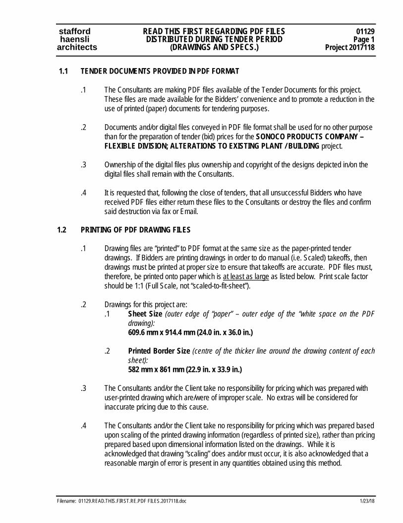
stafford READ THIS FIRST REGARDING PDF FILES 01129 haensli DISTRIBUTED DURING TENDER PERIOD Page 1 architects (DRAWINGS AND SPECS.) Project 2017118
Filename: 01129.READ.THIS.FIRST.RE.PDF FILES.2017118.doc 1/23/18
1.1 TENDER DOCUMENTS PROVIDED IN PDF FORMAT
.1 The Consultants are making PDF files available of the Tender Documents for this project. These files are made available for the Bidders’ convenience and to promote a reduction in the use of printed (paper) documents for tendering purposes.
.2 Documents and/or digital files conveyed in PDF file format shall be used for no other purpose
than for the preparation of tender (bid) prices for the SONOCO PRODUCTS COMPANY – FLEXIBLE DIVISION; ALTERATIONS TO EXISTING PLANT / BUILDING project.
.3 Ownership of the digital files plus ownership and copyright of the designs depicted in/on the
digital files shall remain with the Consultants. .4 It is requested that, following the close of tenders, that all unsuccessful Bidders who have
received PDF files either return these files to the Consultants or destroy the files and confirm said destruction via fax or Email.
1.2 PRINTING OF PDF DRAWING FILES
.1 Drawing files are “printed” to PDF format at the same size as the paper-printed tender drawings. If Bidders are printing drawings in order to do manual (i.e. Scaled) takeoffs, then drawings must be printed at proper size to ensure that takeoffs are accurate. PDF files must, therefore, be printed onto paper which is at least as large as listed below. Print scale factor should be 1:1 (Full Scale, not “scaled-to-fit-sheet”).
.2 Drawings for this project are:
.1 Sheet Size (outer edge of “paper” – outer edge of the “white space on the PDF drawing):
609.6 mm x 914.4 mm (24.0 in. x 36.0 in.) .2 Printed Border Size (centre of the thicker line around the drawing content of each
sheet): 582 mm x 861 mm (22.9 in. x 33.9 in.)
.3 The Consultants and/or the Client take no responsibility for pricing which was prepared with
user-printed drawing which are/were of improper scale. No extras will be considered for inaccurate pricing due to this cause.
.4 The Consultants and/or the Client take no responsibility for pricing which was prepared based
upon scaling of the printed drawing information (regardless of printed size), rather than pricing prepared based upon dimensional information listed on the drawings. While it is acknowledged that drawing “scaling” does and/or must occur, it is also acknowledged that a reasonable margin of error is present in any quantities obtained using this method.
01129 READ THIS FIRST REGARDING PDF FILES stafford Page 2 DISTRIBUTED DURING TENDER PERIOD haensli Project 2017118 (DRAWINGS AND SPECS.) architects
1/23/18 Filename: 01129.READ.THIS.FIRST.RE.PDF FILES.2017118.doc
1.3 PRINTING OF PDF SPECIFICATIONS FILES, ETC.
.1 Specifications, Tender Forms, Auxiliary Information, Architectural Detail (AD) Drawings, Detail Sheets, Schedules and other (small-sized) files are “printed” to PDF format intended for “Letter”-sized paper (215.9 mm x 279.4 mm) / (8.5 in. x 11.0 in.).
.2 These files may be printed using any normal letter-sized printer, since information on these
sheets is (generally) not scale-sensitive. .3 The Consultants make no representation that AD Drawings and other Detail Sheets, when
printed from PDF files on letter-sized paper, will be to actual drawing scale (where applicable). AD Drawings and other Detail Sheets are not to be scaled.
END OF SECTION 01129

stafford 01400 haensli
architects CONSTRUCTION AND CONTRACT
QUALITY CONTROL Page 1
Project 2017118
Filename: 01400.Quality Control.2017118 3/21/16
1 GENERAL
1.0 This Section/Division includes general requirements and/or instructions which apply throughout the
duration of the Work of the Contract. Items listed include standard specification requirements as well as items created/provided by Owner.
1.1 REQUIREMENTS INCLUDED
1.3 Inspection – General Review and Standard Inspections 1.4 Inspection and Testing Agencies 1.5 Specialty (Trade-By-Trade) Independent Inspection and Testing 1.6 Testing and Mix Designs 1.7 Mock-Ups 1.8 Mill Tests 1.9 Equipment and Systems 1.10 Building Air/Vapour/Moisture Seal 1.11 Execution and Workmanship – General 1.12 Coordination 1.13 Concealment 1.14 Regulating Documents 1.15 Conformance and Substitution 1.16 Location of Equipment and Fixtures 1.17 Fastenings: General 1.18 Inspection and Take-Over Procedures When Nearing Completion 1.19 Deficiency Correction and Contract Funds at Close-Out
1.2 RELATED REQUIREMENTS
.1 Section 01010 – Genera Requirements (Broadscope Section) .2 Section 01050 - Field Engineering (Narrowscope Section) .3 Section 01300 - Submittals (Narrowscope Section) .4 Section 01320 - Project Schedules (Narrowscope Section) .5 Section 01340 - Shop Drawings, Product Data, Samples & Mock-Ups (Narrowscope) .6 Section 01410 - Testing Laboratory Services (Narrowscope Section) .7 Section 01500 - Construction Facilities and Temporary Controls (Narrowscope) .8 Section 01545 - Safety Requirements (Narrowscope Section) .9 Section 01600 - Material, Equipment and Procedures (Narrowscope Section) .10 Section 01670 - Systems Demonstrations (Narrowscope Section) .11 Section 01700 - Contract Closeout (Narrowscope Section) .12 Section 01710 - Cleaning (Narrowscope Section) .13 Section 01720 - Project Record Documents (Narrowscope Section) .14 Section 01740 - Warranties, Guarantees and Bonds (Narrowscope Section) .15 Section 01750 - Maintenance Materials, Special Tools and Spare Parts (Narrowscope) .16 Section 01800 - Maintenance Requirements (Narrowscope Section)
01400 stafford Page 2 Project 2017118
CONSTRUCTION AND CONTRACT QUALITY CONTROL
haensli architects
3/21/16 Filename: 01400.Quality Control.2017118
1.3 INSPECTION – GENERAL REVIEW AND STANDARD INSPECTIONS
.1 The Owner and the Consultant shall have access to the Work. If parts of the Work are in preparation at locations other than the Place of the Work, access shall be given to such work whenever it is in progress.
.2 Give timely notice requesting inspection if Work is designated for special tests, inspections or
approvals by Consultant instructions, or the law of the Place of the Work.
.3 If the Contractor covers or permits to be covered Work that has been designated for special tests, inspections or approvals before such is made, uncover such Work, have the inspections or tests satisfactorily completed and make good such Work.
.4 The Consultant may order any part of the Work to be examined if such work is suspected to
be not in accordance with the Contract Documents. If, upon examination such work is found not in accordance with the Contract Documents, correct such work and pay the cost of examination and correction. If such Work is found in accordance with the Contract Documents, the Owner will pay the cost of examination and replacement.
1.4 INSPECTION AND TESTING AGENCIES
.1 Refer to Section 01410 - Testing Laboratory Services and individual trade sections for requirements of specialized testing.
.2 Costs of independent inspection and testing shall be paid for by Cash Allowance. Refer to
Section 01020 - Allowances.
1.5 SPECIALTY (Trade-By-Trade) INDEPENDENT INSPECTION AND TESTING
.1 General
.1 The Owner and Consultant reserve the right to designate, as the project progresses, certain construction materials, components, assemblies, etc. to be subject to independent inspection, testing and/or review.
.2 The following building construction materials, components, assemblies, etc. (as
applicable to the construction involved) may be subject to independent inspection, testing and/or review on this project: .1 Asphalt Paving (02510) – full time inspection during installation / application
of base and asphalt paving courses.
.2 Masonry (04000) – specialty inspection by representative of Ontario Masonry Contractors Association (OMCA)
stafford 01400 haensli
architects CONSTRUCTION AND CONTRACT
QUALITY CONTROL Page 3
Project 2017118
Filename: 01400.Quality Control.2017118 3/21/16
.3 Architectural Woodwork (Millwork) (06400) – inspection by AWMAC.
Inspection and reporting will compare actual construction and installation to AWMAC standards.
.4 Built-up Bituminous Roofing (07511) – inspection and reporting by
designated Roofing Inspector.
.5 Sheet Metal Roofing, Flashings (07610, 07620) - inspection and reporting by designated Roofing Inspector.
.6 Ceramic/Porcelain Tile installations (09310) – inspection and “chain
testing” by TTMAC. Inspection and reporting will compare actual installation to TTMAC standards and project details. “Chain Testing” will be performed to verify that all ceramic/porcelain tiles and base units are fully bonded to substrate.
.7 Painting (09900) – inspection by Ontario Painting Contractor’s Association
under the Ontario Painting Contractor’s Association Architectural Specification program.
.3 Contractor shall cooperate with these specialty inspection programs. Contractor shall assist in
the coordination of timing of inspections and reviews to suit construction progress and deficiency correction time periods.
.4
Deficiencies and/or recommendations as identified on specialty reports shall be treated as if issued by the Consultant. Any items identified as deficient which, in the opinion of the Contractor, are not part of the contracted scope of work, shall be brought to the attention of the Consultant for resolution.
.2
Acce
ss to Work .1 The Contractor for this Work shall, at all times allow the Owner, or any other Owner
commissioned Contractor or their employees, access into the building or around the premises, undisturbed, whether union or non-union, as may be required in the execution of other portions of the building Work and installation of equipment, etc.
.2
The Contractor shall give timely notice requesting inspection if Work is designated for special tests, inspections, or approvals by the Consultants, or any other authorized Owner Staff or testing and Inspection Company, or Authorities Having Jurisdiction.
.3
If the Contractor covers, or permits to be covered Work that has been designated as outlined above, the Contractor shall uncover such Work, have the inspections and tests satisfactorily completed and make good such Work at no additional cost to the Owner.

01400 stafford Page 4 Project 2017118
CONSTRUCTION AND CONTRACT QUALITY CONTROL
haensli architects
3/21/16 Filename: 01400.Quality Control.2017118
.4 The Consultants or the authorized Owner Staff may order any part of the Work to be
examined, if such Work is suspected not to be according to the Contract Documents. If, upon examination, such Work is found not to be in accordance with the Contract Documents, then the Contractor shall correct such Work and pay for cost of examination and correction. If such Work is found to be in full accordance with the Contract Documents, the Owner shall pay for the cost of examination and making good.
.5 The Contractor shall provide any tools, materials or equipment that may be required by the
inspection and/or testing agencies in re-testing the Work. (E.g. Video camera rental to re- inspect incorrectly installed sewer lines.)
.6 If defects are revealed during inspection and/or testing, the appointed agency may request
additional inspection and/or testing to ascertain full degree of defects. The Contractor shall correct the defects and irregularities as reported by the inspection and/or testing agency, at no additional cost to the Owner and the Contractor shall pay all associated costs for re-testing and re-inspection.
.3 Procedures
.1 Notify the appropriate agency and Consultant in advance of the requirement for tests, in order
that attendance arrangements can be made.
.2 Submit samples and/or materials required for testing, as specifically requested in specifications. Submit with reasonable promptness and in an orderly sequence so as not to cause delay in the Work.
.3 Provide labour and facilities to obtain and handle samples and materials on site. Provide
sufficient space to store and cure test samples.
.4 Rejected Work
.1 Remove defective Work, whether the result of poor workmanship, use of defective products or damage and whether incorporated in the Work or not, which has been rejected by the Consultant as failing to conform to the Contract Documents. Replace or re-execute in accordance with the Contract Documents.
.2 Replacement and execution of the affected Work shall be done in full accordance with the
Contract Documents, and the Contractor shall make good other Sub-Contractor’s Work damaged by such removals or replacements at no additional charge to the Owner.
.3 If in the opinion of the Consultant it is not expedient to correct defective Work or Work not
performed in accordance with the Contract Documents, the Owner may deduct from the Contract Price the difference in value between the Work performed and that called for by the Contract Documents, the amount of which shall be determined by the Consultant.
stafford 01400 haensli
architects CONSTRUCTION AND CONTRACT
QUALITY CONTROL Page 5
Project 2017118
Filename: 01400.Quality Control.2017118 3/21/16
.4 The notable exception to the above item is a faulty installation of base and asphalt paving. If,
the inspection agency, after performing random test holes to determine compaction and thickness of sub base, base and asphalt, concludes that either one, or both, are not according to what was specified in the Contract Documents, the Owner will not accept credits for such inconsistencies but rather, demand that any such installation be removed and redone in its entirety, at the pleasure and convenience of the Owner, but within the first year of the warranty period.
.5 Reports
.1 Submit one (1) copy of inspection and testing reports promptly to each of the Consultant and
Owner and one (1) additional copy to Structural, Mechanical and/or Electrical Consultants whenever their respective work is involved.
.2 Provide copies to Subcontractor of work being inspected/tested and manufacturer/fabricator of
material being inspected/tested.
.3 Provide one (1) copy of inspection and testing reports to Municipal Authorities (Building Department) if so requested by these authorities at beginning of project.
1.6 TEST AND MIX DESIGNS
.1 Furnish test results and mix designs as may be requested.
.2 The cost of tests and mix designs beyond those called for in the Contract Documents or beyond those required by the Law of the Place of Work shall be appraised by the Consultant and may be authorized as recoverable.
1.7 MOCK-UPS
.1 Refer to Section 01340 - Shop Drawings, Product Data, Samples and Mock-Ups. Prepare mock-ups for Work specifically requested in the specifications. Include for Work of all Sections required to provide mock-ups. Erect mock-ups in locations acceptable to Consultant. Prepare mock-ups for Consultant review with reasonable promptness and in an orderly sequence, so as not to cause any delay in the Work.
.2 Failure to prepare mock-ups in ample time is not considered sufficient reason for an extension
of Contract Time and no claim for extension by reason of such default will be allowed.
.3 Remove mock-ups at conclusion of Work or when acceptable to Consultant.
.4 Reviewed and accepted mock-ups will become standards of workmanship and material against which installed work will be verified.

01400 stafford Page 6 Project 2017118
CONSTRUCTION AND CONTRACT QUALITY CONTROL
haensli architects
3/21/16 Filename: 01400.Quality Control.2017118
1.8 MILL TESTS
.1 Submit mill test certificates as required of the specification Sections.
1.9 EQUIPMENT AND SYSTEMS
.1 Submit Testing, Adjusting and Balancing reports for mechanical, electrical and building equipment systems.
.2 Refer to other applicable sections for definitive requirements with respect to systems
demonstrations and/or instructions.
1.10 BUILDING AIR/VAPOUR/MOISTURE SEAL
.1 It is the intent of the drawings, details, specifications, etc. (Contract Documents) that the finished building achieve a complete and uninterrupted air and vapour barrier between interior and exterior.
.2 The Contractor shall perform Work to ensure that exterior walls, windows, floor and roof
surfaces provide an airtight and vapour-tight membrane to prevent problems due to building vapour migration.
.3 In general, the air/vapour barrier must be achieved on the interior side of the thermal
insulation. Refer to individual trade sections for specific products and/or procedures to be used and/or followed. Ensure and coordinate the work of separate subtrades whose work form(s) part(s) of the overall building air/vapour seal.
.4 Should one or more aspects of the construction be (apparently) unable to achieve the required
air/vapour barrier when constructed as planned, the Contractor shall make formal written inquiry of the Consultant in order to receive clarification(s) and/or instruction(s).
1.11 EXECUTION AND WORKMANSHIP - GENERAL
.1 Workmanship shall be the best quality, executed by workers experienced and skilled in the respective duties for which they are employed.
.2 Only competent personnel will be permitted on site. The Contractor will cause to remove from
the site any persons not observing or complying with safety requirements.
.3 Contract documents may stipulate, for particular sections of Work, more precise requirements than as described in .1 above, in which case the more precise requirements shall govern.
.4 Immediately notify the Consultant if required Work is such as to make it impractical to produce
required results.
stafford 01400 haensli
architects CONSTRUCTION AND CONTRACT
QUALITY CONTROL Page 7
Project 2017118
Filename: 01400.Quality Control.2017118 3/21/16
.5 Do not employ any unfit person or anyone unskilled in their required duties. The Consultant reserves the right to require the dismissal from the site, workers deemed incompetent, careless, insubordinate or otherwise objectionable.
.6 Decisions as to the quality or fitness of workmanship in cases of dispute rest solely with the
Consultant, whose decision is final.
.7 Perform Work in a neat and careful manner to retain Work plumb, true and square. Ensure that various Work components are properly installed, forming tight joints and appropriately aligned junctions, edges and surfaces, free of warps, twists, waves, or other such irregularities.
.8 Wherever indicated on the drawings or Specifications, or in the manufacturers’ and/or
suppliers’ written instructions, arrange to have manufacturers’ and/or installers’ representatives inspect the Work that incorporates their materials, products or items.
.9 None of the Contractors shall permit materials to come in contact with other materials if such
conditions may result in corrosion, staining, discolouration or deterioration of the completed Work. Provide compatible, durable separators where such contact is unavoidable.
.10 Writings, overspray, spills, or markings of any kind must not be visible after application of any
finish surface coatings, and must not adversely affect the application and adhesion of such coatings. Exposed surfaces not specified to receive a finished or opaque covering surface material must be left clean and clear of any such markings, otherwise the Contractor must suitably clean and clear the surfaces, or provide a suitable covering coating over the entire area that is approved by the Consultant.
.11 Galvanized steel (including lintels at masonry openings) must not be allowed to become
stained or discoloured by exposure to or contact with other chemicals or materials (including soil if stored on the ground). If there is such staining or discolouration visible after installation (including overspray of cavity wall insulation) a full and complete coating of galvafroid paint must be applied to maintain uniformity of colour and appearance.
.12 The Owner may hire Commissioners to perform inspections of building systems at the closing stages of the Work of this Contract. The Contractor shall co-operate with, and co-ordinate the Work of, the Owner's Commissioners at the Place of Work.
.13 If the Contractor is responsible for a delay in the progress of the Work due to an infraction of
legislation or Owner Health and Safety requirements, the Contractor will, without additional cost to the Owner, work such overtime, and acquire and use for the execution of the Work such additional labour and equipment as to be necessary, in the sole opinions of the Owner's Representative and Consultant, to avoid delay in the final completion of the Work or any operations thereof.
01400 stafford Page 8 Project 2017118
CONSTRUCTION AND CONTRACT QUALITY CONTROL
haensli architects
3/21/16 Filename: 01400.Quality Control.2017118
1.12 COORDINATION
.1 Ensure co-operation of workers in laying out Work. Maintain efficient and continuous supervision.
.2 Be responsible for co-ordination and placement of openings, sleeves and accessories.
.3 The Contractor shall co-ordinate all the work and preparation on which subsequent Work
depends to facilitate mutual progress, and to prevent any conflict.
.4 The Contractor shall ensure that each Sub-Contractor makes known, for the information of the Contractor and other Sub-Contractors, the environmental and surface conditions required for the execution of their individual Work; and that each Sub-Contractor makes known the sequence of others' Work required for installation of Work.
.5 The Contractor shall ensure that each Sub-Contractor, before commencing Work, knows the
requirements for subsequent Work and that each Sub-Contractor is assisted in the execution of the preparatory Work by Sub-Contractors on which other Work depends.
.6 The Contractor shall ensure that shop and layout drawings, templates, and all information
necessary for the location and installation of materials, openings, inserts, anchors, accessories, fastenings, connections and access panels are provided by each Sub-Contractor whose Work requires co-operative location and installation by other Sub-Contractors and that such information is communicated to the applicable installer.
.7 The Contractor shall ensure that delivery of materials supplied by one Sub-Contractor to be
installed by another Sub-Contractor is well before the installation begins.
.8 The Contractor shall inform all Sub-Contractors that giving installation information in error, or too late to incorporate in the Work, shall be their responsibility for any extra Work caused by such error or delay. The Owner will not entertain any extras in this regard.
.9 The Contractor shall coordinate locations of electrical receptacles (prior to installation) with
locations millwork units, white boards, tack board locations to avoid interference.
1.13 CONCEALMENT
.1 In finished areas, conceal pipes, ducts and wiring in floors, walls and ceilings, except where indicated otherwise. If in doubt as to method of concealment, or intent of the Contract Documents in this regard, request clarification from the Consultant before proceeding with the Work.
.2 Before installation, inform the Consultant if there is a contradictory situation. Install as directed
by Consultant.
stafford 01400 haensli
architects CONSTRUCTION AND CONTRACT
QUALITY CONTROL Page 9
Project 2017118
Filename: 01400.Quality Control.2017118 3/21/16
1.15 REGULATING DOCUMENTS
.1 The Contractor and Sub-Contractors, Suppliers/Installers etc., must conform to the Ontario Building Code (Ontario Reg. 413/90), Canadian Mechanical Code (CEC), CAN3-B44-M85 and W59-1989, The Occupational Health and Safety Act, Ontario, 1990 (Bill 208), the National Fire Code, the local Municipal Fire Code, and all other applicable Codes and Building By-Laws. \
.2 All must also conform to the requirements of the Authorities Having Jurisdiction, such as
Public Utilities. Where required under The Occupational Health and Safety Act, engage a Professional Engineer to design formwork and false work for concrete.
.3 Contract forms, codes, standards and manuals referred to in these specifications are the
latest published editions at the date of close of tenders. The Contractor, Sub-Contractors, and Suppliers/Installers must meet or exceed the requirements of specified standards.
.4 Keep on site, copies of documents referred to in the Specification for joint use of the
Contractor and the Consultant.
1.16 CONFORMANCE AND SUBSTITUTION
.1 When products are specified by standard or performance specifications, upon request of Consultant, obtain from manufacturer an independent testing laboratory report, stating that material or equipment meets or exceeds specified requirements.
.2 Proposals for substitution may be submitted only after award of contract. Such requests must include statements of respective costs of items originally specified and proposed substitutions. Proposals will be considered by Consultant if: .1 Products selected by tenderer from those specified are not available, or .2 Delivery date of products selected from those specified would unduly delay
completion of Contract, or .3 Alternative products to those specified, which are brought to attention of, and
considered by Consultant as equivalent to those specified and will result in credit to Contract amount.
.3 Should proposed substitution be accepted either in part or in whole, assume full responsibility
and costs when substitution affects other work on project. Pay for design and drawing changes required as result of substitution.
.4 Amounts of all credits arising from approval of substitutions will be determined by Consultant
and Contract Price will be reduced accordingly. No substitutions will be permitted without prior written approval of Consultant.
.5 Contractor shall assume all responsibility for ensuring that the proposed substitute materials,
devices, systems, etc. can be installed or constructed in the building as designed. Provide complete information to Consultant as required to confirm size, weight, capacity, performance, interface, etc.
01400 stafford Page 10 Project 2017118
CONSTRUCTION AND CONTRACT QUALITY CONTROL
haensli architects
3/21/16 Filename: 01400.Quality Control.2017118
1.17 LOCATION OF EQUIPMENT AND FIXTURES
.1 Location of equipment, fixtures and outlets indicated or specified are to be considered as
approximate. Locate equipment, fixtures and distribution systems to provide minimum interference and maximum usable space and in accordance with manufacturer's recommendations for safety, access and maintenance.
.2 Lay out Mechanical and Electrical Work well in advance of concrete placement and furring
installation to allow for proper concealment. Test and inspect Work before applying pipe covering and before it is concealed.
.3 Provide and maintain control lines and levels required for the Work. Lay out the Work in
accordance with these lines and levels and dimensions indicated on Drawings.
.4 Verify lines, levels and dimensions and report any errors or inconsistencies on the Drawings to the Consultants.
.5 Inform Consultant of impending installation and obtain approval for actual location.
.6 Submit field drawings to indicate relative position of various services and equipment when
required by Consultant.
1.18 FASTENINGS: GENERAL
.1 Provide metal fastenings and accessories in same texture, colour and finish as base metal in which they occur.
.2 Prevent electrolytic action between dissimilar metals. Use non-corrosive fasteners, anchors
and spacers for securing exterior work.
.3 Space anchors within limits of load bearing or shear capacity and ensure that they provide positive permanent anchorage. Wood plugs not acceptable.
.4 Keep exposed fastenings to minimum, space evenly and lay out neatly.
.5 Fastenings which cause spalling or cracking of material to which anchorage is made are not
acceptable.
.6 Obtain Consultant approval before using explosive actuated fastening devices. If approval is obtained comply with CSA Z166-1975.
1.19 INSPECTION AND TAKE-OVER PROCEDURES WHEN NEARING COMPLETION
.1 The requirements of OAA/OGCA Document No. 100 "Take-Over Procedures" shall be applicable in addition to requirements listed in the Specifications.

stafford 01400 haensli
architects CONSTRUCTION AND CONTRACT
QUALITY CONTROL Page 11
Project 2017118
Filename: 01400.Quality Control.2017118 3/21/16
.2 Prior to application for certificate of Substantial Performance, carefully inspect the Work and ensure it is complete, that major and minor construction deficiencies are complete and/or corrected and the building is clean and in condition for occupancy. Notify the Consultant, in writing, of satisfactory completion of the Work and request an inspection.
.3 During the Consultant inspection, a list of deficiencies and defects will be tabulated. Correct
same.
.4 When the Consultant considers deficiencies and defects have been corrected and it appears requirements of the Contract have been substantially performed, make application for certificate of Substantial Performance. Refer to Standard Contract Document PDSB - 2011 – Stipulated Price Contract and also to OGCA Document No. 100 for specifics to application.
.5 Note that Completion Security Account will not be paid or released until all of the Contract
Close-Out requirements have been fulfilled. Refer to Standard Contract Document PDSB - 2011 – Stipulated Price Contract and OGCA Document No. 100 for specifics.
1.20 DEFICIENCY CORRECTION AND CONTRACT FUNDS AT CLOSE-OUT
.1 It is the intent of the Owner and the Consultants to have the correction of listed deficiencies accomplished in a timely manner. The Owner and Consultants believe that it is in all parties’ best interests to complete the correction of deficiencies quickly, to allow the project accounting to be concluded expeditiously.
.2 The procedures listed below involve removal of funds from the Contract in the event that
deficiencies are not corrected within the stated timeframes. It is not the desire of the Owner or Consultants to remove funds from the Contract to fund completion work by an outside Contractor – this will only be undertaken if the Contractor fails to put forth the required effort to correct the deficiencies.
.3 The following requirements and procedures will be implemented and followed for this project:
.1 The Consultant perform a deficiency review/ inspection of the project (or portion
thereof which is sufficiently complete to have said inspection). This (first) deficiency review/ inspection will be undertaken following the issuance of the Certificate of Substantial Performance – it will not take place before this event under any circumstances. The initial review/ inspection field and office work make take up to 10 working days to complete.
.2 The Consultant will issue a Deficiency List for the project (or portion thereof). The
Deficiency List will include a dollar value for each item (schedule of values). The amounts listed will be established by the Consultant based upon best available information at the time of review – these values shall estimate the cost of hiring an outside, independent Contractor to attend the project and correct the listed deficiencies (they will not be established as the cost of deficiency correction by
01400 stafford Page 12 Project 2017118
CONSTRUCTION AND CONTRACT QUALITY CONTROL
haensli architects
3/21/16 Filename: 01400.Quality Control.2017118
Contractor’s / Subcontractor’s forces, executed while at the site to attend to other (in Contract) Work). .
.3 The Contractor shall correct the deficiencies noted on the Deficiency List, including
coordination of sub-trade work. The Contractor shall update the Deficiency List by crossing off those items completed/corrected and/or by making notes regarding those items not corrected or partially corrected. Deficiency correction is to be undertaken in a timely manner.
.4 The Consultant will perform a general update-review of the progress of deficiency
correction approximately 30 days following the date of issue of the Deficiency List. The Consultant will issue a general memo regarding the approximate progress of correction of deficiencies, including a statement as to whether the Consultant believes that the Contractor is on schedule for full completion within 45 days of the date of issue of the Deficiency List.
.5 The Consultant will perform a re-inspection of the project approximately 45 days
following the date of issue of the Deficiency List. The Deficiency List will be updated following the inspection, including an update to the schedule of values. The updated Deficiency List will be issued to Owner and Contractor.
.6 The Contractor will have ten (10) business days to respond to the updated Deficiency
List with respect to reasons why items listed have not, or could not, be corrected during the forty-five (45) day period allotted.
.7 Following the ten (10) day response period, the Consultant will prepare a Credit
Change Order; such Change Order will remove the value of the outstanding deficiencies from the Contract and the Scope of Work. The Contractor will thereafter not be responsible for correction of this work. All warranties with respect to the work items in question shall remain in effect.
.8 The Consultant and/or the Owner will undertake to obtain another Contractor to
attend the project and correct the uncorrected deficiencies as described above. This work will be undertaken when the original Contractor is no longer performing work on the site (or portion of the project which was the subject of the above-described Deficiency List).
.9 Refer also to Document 00810 – Supplementary General Conditions to CCDDC 2 –
2008 for confirmation of the above requirements and procedulres and/or for further requirements.
.4 In the event that the procedures outlined in Item .3 above are not followed to completion,
Contractor is hereby advised that the Consultant will perform a total of three (3) deficiency inspections / reviews, including the initial review to establish the Deficiency List, as part of normal services.
stafford 01400 haensli
architects CONSTRUCTION AND CONTRACT
QUALITY CONTROL Page 13
Project 2017118
Filename: 01400.Quality Control.2017118 3/21/16
.1 Additional inspections required to re-evaluate outstanding deficiency corrections
and/or to determine Total Performance of the Contract, will be invoiced to the Contractor based upon hours expended for site visits, reviews and subsequent reports. Hourly rate for said work will be $90.00 per hour, plus HST.
.2 Payment for above invoices shall be removed from Construction Contract Amount via
Credit Change Order, if invoices are not paid in full within 30 days of issue.
.3 It is the intent of the Owner and the Consultant that Construction Contract Funds shall not be fully certified and paid until all of the Contract Close-Out requirements have been fulfilled. Refer also to Document 00810 – Supplementary Conditions for confirmation of the above requirements and procedulres and/or for further requirements.
END OF SECTION 01400

01400 stafford Page 14 Project 2017118
CONSTRUCTION AND CONTRACT QUALITY CONTROL
haensli architects
3/21/16 Filename: 01400.Quality Control.2017118
This Page is Intentionally Left Blank
stafford 02060 haensli DEMOLITION OF STRUCTURES Page 1 architects Project 2017118
Filename: 02060.DemolitionStructures.2017118.doc 1/23/18
1 General 1.1 RELATED WORK .1 Section 01001 - Summary of Work and Special Requirements .2 Section 01010 - General Requirements .3 Section 01045 - Cutting and Patching 1.2 REFERENCE STANDARDS
.1 Do blasting operations in accordance with requirements of CSA S350, except where specified otherwise. Notify Consultant in writing if blasting is contemplated or required prior to commencement of work or bringing explosive materials onto site.
1.3 EXISTING CONDITIONS
.1 Take over structures to be demolished based on their condition on date that tender is accepted.
.2 Demolition of spray or trowel-applied asbestos can be hazardous to health. Should material
resembling spray or trowel-applied asbestos be encountered in the course of demolition work (other than that identified elsewhere in the Tender Documents) stop work and notify the Consultant immediately. Do not proceed until written instructions have been received from the Consultant.
1.4 DEMOLITION DRAWINGS
.1 Where required by authorities having jurisdiction, submit for approval drawings, diagrams or details showing sequence of disassembly work or supporting structures and underpinning.
.2 Drawings for structural elements shall bear stamp of qualified professional engineer
registered in the Province of Ontario. 1.5 PROTECTION
.1 Prevent movement, settlement or damage of adjacent structures, services, walks, paving, trees, landscaping, adjacent grades parts of existing building to remain. Provide bracing, shoring and underpinning required. Make good damage and be liable for injury caused by demolition.
.2 Take precautions to support structures and, if safety of building being demolished or adjacent
structures or services appears to be endangered, cease operations and notify Consultant.
02060 stafford Page 2 DEMOLITION OF STRUCTURES haensli Project 2017118 architects
1/23/18 Filename: 02060.DemolitionStructures.2017118.doc
.3 Prevent debris from blocking surface drainage system, elevators, mechanical and electrical systems which must remain in operation.
1.6 CONSTRUCTION PHOTOGRAPHS
.1 During all operations of demolition of structures record significant operations as directed by Consultant using photography.
.2 Photographs to record interior and exterior conditions at the following stages of demolition of
structures: .1 Prior to commencing work. .2 Following removal of ceilings and other enclosure surfaces. .3 Following removal of piping and/or ductwork and/or conduit. .4 Following removal of floor or roof structures and surfaces. .5 Following removal of walls. .6 Following final cleanup in preparation for construction. .3 Record all significant alterations to structural elements not involving full demolition or removal
(cutting of holes into walls, beams, piers, etc. greater than 1/5 their minimum structural dimension, partial removal of beams, columns, piers, walls, etc.).
.4 Submit two (2) sets of colour prints to Consultant, once per week during demolition activities.
Prints to be individually labelled on back briefly stating location (room name/number) and date.
2 Products (not applicable) 3 Execution 3.1 WORK
.1 Dispose of demolished materials except where noted otherwise and in accordance with authorities having jurisdiction.
.2 Carefully remove materials and equipment indicated for salvage or re-use, store, protect, and
reinstall in new building, using qualified tradesmen leave ready for installation by other sections of the work.
.3 Carefully remove materials and equipment indicated for removal and turn-over to Owner,
store in location designated by Owner.
stafford 02060 haensli DEMOLITION OF STRUCTURES Page 3 architects Project 2017118
Filename: 02060.DemolitionStructures.2017118.doc 1/23/18
3.2 SAFETY CODE
.1 Unless otherwise specified, carry out demolition work in accordance with Section 01545 - Safety Requirements.
3.3 PREPARATION
.1 Disconnect electrical, telephone and cable TV service lines entering buildings to be demolished in accordance with rules and regulations of authorities having jurisdiction. Post warning signs on electrical lines and equipment which must remain energized to serve other areas of building during period of demolition. Remove electrical, telephone and cable TV lines to within 3 metres of property line if buried; to poles at property lines if above grade.
.2 Disconnect, remove and cap designated mechanical services in accordance with
requirements of local authority having jurisdiction. Remove water, gas, sanitary and storm lines to within 3 metres of property lines, or as indicated (if some on-site portions may remain). Install stakes (at grade) with permanent labels at ends of all capped lines to indicate location and extent of buried services to future contractors. .1 Natural gas supply lines to be removed by qualified tradesman in accordance with
gas company instructions. .2 Remove sewer and water lines to property line and cap to prevent leakage. .3 Remove and cap other underground services. .4 Measure and record depth or invert elevations of all buried services remaining in
ground. .3 Do not disrupt active or energized utilities traversing premises designated to remain
undisturbed. .4 Protect existing portions of building which are to remain. Seal all openings (doors, windows,
etc.) to prevent dust intrusion. Protect existing roof surfaces and roof-mounted equipment to remain. Cut and/or carefully remove exterior and interior masonry components at junctions of “existing-to-be-removed” and “existing-to-remain” sections of the building.
.5 Employ rodent and vermin exterminators to comply with health regulations.
3.4 DEMOLITION
.1 Demolish partial structures and remove existing equipment as indicated. Portions of the existing buildings are to remain – ensure that demolition operations and procedures do not damage portions to remain. Carefully disconnect all structural elements from existing-to-remain portion prior to large scale demolition, to ensure that demolition stresses are not transferred to existing-to-remain portions.
02060 stafford Page 4 DEMOLITION OF STRUCTURES haensli Project 2017118 architects
1/23/18 Filename: 02060.DemolitionStructures.2017118.doc
.2 Demolish and/or remove parts and/or components within the existing buildings (portion to remain) to permit construction of addition and remedial work as indicated.
.3 Demolish foundation walls to full depth below finished grade beyond area of new
construction. .4 Demolish basement and/or foundation walls and footings to full depth, and concrete floors
below or on grade within areas of new construction. .5 Pieces of concrete and masonry broken from demolition work to be removed from open
basements or excavations. Remove from worksite. .6 Remove existing equipment, services, and obstacles where required for refinishing or making
good of existing surfaces, and replace as work progresses. .7 At end of each day's work, leave work in safe condition so that no part is in danger of toppling
or falling. Protect interiors of parts not to be demolished from exterior elements at all times. .8 Demolish to minimize dusting. Keep dusty materials wetted. .9 Demolish masonry and concrete walls in small sections. Carefully remove and lower structural
framing and other heavy or large objects. .10 Do not sell or burn materials on site. .11 Remove contaminated or dangerous materials from site and dispose of in safe manner to
minimize danger at site or during disposal. Comply with all regulations and by-laws of Municipal and Provincial Authorities having jurisdiction.
3.5 GENERAL DESCRIPTION AND REQUIREMENTS
.1 Refer to Architectural drawings for extent of demolition required. Refer to notes on all other drawings. Demolition work shall be (generally) to include the selective (partial) demolition and disposal of components and assemblies forming parts of the existing building. Most of the existing building is to be preserved and re-used in its present form - as indicated on the Tender Documents.
.2 Drawings and notes are intended to convey the general intent of demolition and removal
required for the work of this Contract but are not intended to highlight or point out every element requiring demolition or removal. Contractor is to review drawings and specifications which indicate the required finished project and perform the demolition required to allow the indicated changes and/or construction to take place.
stafford 02060 haensli DEMOLITION OF STRUCTURES Page 5 architects Project 2017118
Filename: 02060.DemolitionStructures.2017118.doc 1/23/18
.3 Contractor shall demolish related and/or adjacent and/or supported and/or supporting building elements as required to accomplish the indicated demolition. Examples include: .1 Walls to be demolished, which contain mechanical and/or electrical elements –
demolition shall include removal of those related elements. .2 Components to be removed which are above existing ceilings – demolition shall
include removal of ceiling construction which obstructs removal of the specified components.
.3 Components which would cause collapse or damage to other components to be retained – provide temporary shoring or other construction as required to preserve the integrity of components to be retained.
.4 Contractor is to plan and bid the work of this contract as a selective (i.e. partial) demolition
project. As such, the Contractor must allow for unseen conditions, demolition of items which are not fully visible during the bidding phase. It is not possible to indicate all specific items requiring demolition on the drawings.
.5 Inform Consultant immediately if conditions are encountered during demolition which are
significantly beyond those which could have reasonably been anticipated or inferred based upon the Contract Documents and examination of the building prior to commencement of work.
3.6 DEMOLITION REQUIRED DUE TO RELATED CONSTRUCTION
.1 Where documents call for construction work which is obstructed by other construction
elements, work shall include the partial demolition of those obstructing elements as required to accomplish the specified work.
.2 Example of work described in item .1 include structural steel reinforcing which is part of
renovation work but is obstructed by existing ceilings or other surfaces – remove the existing ceilings or other surfaces in order to gain access to the specified work.
3.7 SPECIAL REQUIREMENTS – ITEMS TO BE TURNED OVER TO OWNER
.1 Generally, the Owner will remove all items which it is desired to retain prior to the start of
construction. Carefully disconnect, remove and/or dismount the (remaining) building products and/or assemblies listed below. Reassemble each item or assembly if partial disassembly was required for removal, ensuring that each item/assembly is complete and suitable for re-use/reinstallation.
.2 Collect all similar items and stack on skids or in suitable containers, using protective
measures to prevent damage to individual items. Store on site until all similar items/assemblies are collected and made ready for shipment.
02060 stafford Page 6 DEMOLITION OF STRUCTURES haensli Project 2017118 architects
1/23/18 Filename: 02060.DemolitionStructures.2017118.doc
.3 Contact owner's representative and arrange for pickup and transport by Owner. Provide forklift or other loading mechanism (as appropriate) on site to load materials onto Owner's truck(s).
.4 Items to be removed and turned over to Owner shall include:
.1 Major Items - None Applicable for this project
.2 Other minor items to be designated at time of demolition.
END OF SECTION 02060
stafford 02223 haensli EXCAVATING, TRENCHING AND Page 1 architects BACKFILLING Project 2017118
Filename: 02223.Excavating.Trenching.Backfilling.2017118.DOC 1/23/18
1 General 1.1 RELATED WORK .1 Section 02111 - Clearing and Grubbing .2 Section 02210 - Site Grading .3 Section 02212 - Topsoil Stripping and Sourcing .4 Section 02510 - Asphalt Concrete Paving .5 Section 02520 - Concrete Walks, Curbs and Gutters .6 Section 02950 - Planting of Trees and Shrubs .7 Division 15 - Mechanical Buried Services .8 Division 16 - Electrical Buried Services 1.2 MECHANICAL AND ELECTRICAL INSTALLATIONS
.1 Excavation, trenching and backfilling at Mechanical (Division 15) and Electrical (Division 16) installations is to be included in the work of those (respective) divisions. Co-ordinate the work of this Section with the excavation, trenching and backfilling work of Divisions 15 and 16.
.2 All excavation, trenching and backfilling work for other Sections or Divisions shall meet the
requirements of this Section as well as requirements specified in those other Sections or Divisions. Where conflicts exist in requirements listed, the more stringent requirements shall be applicable.
1.3 DEFINITIONS
.1 Rock Excavation: excavation of material from solid masses of igneous, sedimentary or metamorphic rock which, prior to its removal, was integral with its parent mass, and boulders or rock fragments having individual volume in excess of 1 m3.
.2 Common Excavation: excavation of materials of whatever nature, which are not included
under definitions of rock excavation including dense tills, hardpan, shale, fractured limestone, frozen materials and partially cemented materials which can be ripped and excavated with heavy construction equipment.
.3 Topsoil: material capable of supporting good vegetative growth and suitable for use in top
dressing, landscaping and seeding also as defined in Section 02212 - Topsoil and Finish Grading.
.4 Compaction Densities: for densities listed for compaction of granular materials (i.e. compact
to 99%), the values listed refer to Standard Proctor Maximum Dry Density (SPMDD) values. Values listed are MINIMUM compaction results. If granular materials are inspected / tested and compaction results are found to be lower than the specified values, the loactions in
02223 stafford Page 2 EXCAVATING, TRENCHING AND haensli Project 2017118 BACKFILLING architects
1/23/18 Filename: 02223.Excavating.Trenching.Backfilling.2017118.DOC
question will be rejected. Recompaction / reworking / retesting will be required prior to executing additional work.
1.4 PROTECTION OF EXISTING FEATURES
.1 Existing buried utilities and structures: .1 Size, depth and location of existing utilities and structures as indicated are for
guidance only. Completeness and accuracy are not guaranteed. .2 Prior to commencing any excavation work, notify applicable Owner or Authorities,
establish location and state of use of buried utilities and structures. Clearly mark such locations to prevent disturbance during work.
.3 Confirm locations (and exact invert elevations of water lines and storm/sanitary drainage lines) of buried utilities by careful test excavations.
.4 Maintain and protect from damage, water, sewer, gas, electric, telephone and other utilities and structures encountered. Obtain direction of Consultant before moving or otherwise disturbing utilities or structures.
.5 Advise Consultant and utility company to remove/re-route existing lines in area of excavation. Pay costs for such work except for revisions to utilities not shown on Contract Documents.
.6 Record location of maintained, re-routed and abandoned underground lines. .2 Existing buildings and surface features (as applicable for this site):
.1 Conduct, with Consultant, condition survey of existing buildings, trees and other plants, lawns, fencing, service poles, wires and paving, survey bench marks and monuments (as applicable) which may be affected by work.
.2 Protect existing buildings and surface features which may be affected by work from damage while work is in progress and repair damage resulting from work.
.3 Where excavation necessitates root or branch cutting, do so only as approved by Consultant.
1.5 SHORING, BRACING AND UNDERPINNING
.1 Comply with Section 01545 - Safety Requirements and applicable local regulations and to protect existing features.
.2 Engage services of qualified professional engineer who is registered in Province of Ontario to
design and inspect cofferdams, shoring, bracing and underpinning required for work. .3 At least 2 weeks prior to commencing work, submit design and supporting data. .4 Design and supporting data submitted to bear the stamp and signature of qualified
professional engineer registered in the Province of Ontario.
stafford 02223 haensli EXCAVATING, TRENCHING AND Page 3 architects BACKFILLING Project 2017118
Filename: 02223.Excavating.Trenching.Backfilling.2017118.DOC 1/23/18
.5 Professional engineer responsible for design of temporary structures to submit proof of insurance coverage for professional liability except where engineer is employee of contractor, in which case contractor shall submit proof that work by professional engineer is included in contractor's insurance coverage.
1.6 SAMPLES
.1 At least 2 weeks prior to commencing work, inform Consultant of proposed source of fill materials and provide access for sampling.
.2 Submit 5 kg samples of type of fill specified including representative samples of excavated
material.
.3 Ship samples prepaid to testing laboratory as designated by Consultant, in tightly closed containers to prevent contamination.
1.7 SITE CONDITIONS / GEOTECHNICAL REPORTS
.1 Geotechnical (Sub-Surface/Soils) Investigation reports are bound into the specifications as Document 00220. These reports are for Contractor's information and reference to assist in evaluating the existing site conditions. Instructions, procedures, minimum depths and/or dimensions referenced in the reports shall be followed and adhered to by the Contractor EXCEPT where drawings and/or specifications instruct and/or illustrate construction which is more restrictive, greater size, greater strength, thicker, deeper and/or (generally) more onerous. Addition restrictions which override the soils investigation reports are listed in item .2 below.
.2 The soils investigation reports SHALL NOT be interpreted as granting permission and/or
issuing instructions with respect to: a) substitution of backfill materials to other than those specified in this Section, b) excavation/backfill/compaction methods, or c) compaction performance requirements
.3 Where the soils investigation reports indicate the presence OR possiblity of disturbed soils
and/or existing fill at locations to receive building and/or paving construction, remove all existing materials down to elevations indicated by the soils investigation report to be: .1 Undisturbed material, and .2 Stiff and/or dense material capable of supporting stuctures, and .3 Material which is free of organic materials or contamination.
.4 Notwithstanding item .3 above, excavation shall extend, at minimum, down to elevations indicated on drawings or as required by specified foundation and/or floor construction.
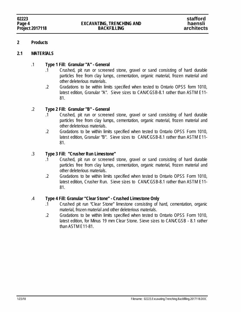
02223 stafford Page 4 EXCAVATING, TRENCHING AND haensli Project 2017118 BACKFILLING architects
1/23/18 Filename: 02223.Excavating.Trenching.Backfilling.2017118.DOC
2 Products 2.1 MATERIALS
.1 Type 1 Fill: Granular "A" - General .1 Crushed, pit run or screened stone, gravel or sand consisting of hard durable
particles free from clay lumps, cementation, organic material, frozen material and other deleterious materials.
.2 Gradations to be within limits specified when tested to Ontario OPSS form 1010, latest edition, Granular "A". Sieve sizes to CAN/CGSB-8.1 rather than ASTM E11-81.
.2 Type 2 Fill: Granular "B" - General
.1 Crushed, pit run or screened stone, gravel or sand consisting of hard durable particles free from clay lumps, cementation, organic material, frozen material and other deleterious materials.
.2 Gradations to be within limits specified when tested to Ontario OPSS Form 1010, latest edition, Granular "B". Sieve sizes to CAN/CGSB-8.1 rather than ASTM E11-81.
.3 Type 3 Fill: "Crusher Run Limestone"
.1 Crushed, pit run or screened stone, gravel or sand consisting of hard durable particles free from clay lumps, cementation, organic material, frozen material and other deleterious materials.
.2 Gradations to be within limits specified when tested to Ontario OPSS Form 1010, latest edition, Crusher Run. Sieve sizes to CAN/CGSB-8.1 rather than ASTM E11-81.
.4 Type 4 Fill: Granular “Clear Stone” - Crushed Limestone Only
.1 Crushed pit run “Clear Stone” limestone consisting of hard, cementation, organic material, frozen material and other deleterious materials.
.2 Gradations to be within limits specified when tested to Ontario OPSS Form 1010, latest edition, for Minus 19 mm Clear Stone. Sieve sizes to CAN/CGSB - 8.1 rather than ASTM E11-81.
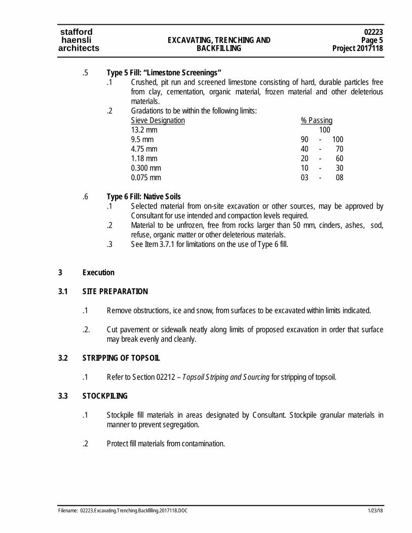
stafford 02223 haensli EXCAVATING, TRENCHING AND Page 5 architects BACKFILLING Project 2017118
Filename: 02223.Excavating.Trenching.Backfilling.2017118.DOC 1/23/18
.5 Type 5 Fill: “Limestone Screenings” .1 Crushed, pit run and screened limestone consisting of hard, durable particles free
from clay, cementation, organic material, frozen material and other deleterious materials.
.2 Gradations to be within the following limits: Sieve Designation % Passing 13.2 mm 100 9.5 mm 90 - 100 4.75 mm 40 - 70 1.18 mm 20 - 60 0.300 mm 10 - 30 0.075 mm 03 - 08
.6 Type 6 Fill: Native Soils
.1 Selected material from on-site excavation or other sources, may be approved by Consultant for use intended and compaction levels required.
.2 Material to be unfrozen, free from rocks larger than 50 mm, cinders, ashes, sod, refuse, organic matter or other deleterious materials.
.3 See Item 3.7.1 for limitations on the use of Type 6 fill.
3 Execution
3.1 SITE PREPARATION
.1 Remove obstructions, ice and snow, from surfaces to be excavated within limits indicated. .2. Cut pavement or sidewalk neatly along limits of proposed excavation in order that surface
may break evenly and cleanly. 3.2 STRIPPING OF TOPSOIL
.1 Refer to Section 02212 – Topsoil Striping and Sourcing for stripping of topsoil. 3.3 STOCKPILING
.1 Stockpile fill materials in areas designated by Consultant. Stockpile granular materials in manner to prevent segregation.
.2 Protect fill materials from contamination.

02223 stafford Page 6 EXCAVATING, TRENCHING AND haensli Project 2017118 BACKFILLING architects
1/23/18 Filename: 02223.Excavating.Trenching.Backfilling.2017118.DOC
3.4 SHORING, BRACING AND UNDERPINNING .1. Comply with Section 01545 - Safety Requirements and applicable local regulations to protect
existing features. .2 Construct temporary works to depths, heights and locations as required for construction of
Work. .3 During backfill operation:
.1 Unless otherwise indicated or directed by Consultant, remove sheeting and shoring from excavations.
.2 Do not remove bracing until backfilling has reached respective levels of such bracing.
3.5 DEWATERING
.1 Keep excavations free of water while work is in progress.
.2 Protect open excavations against flooding and damage due to surface run-off. .3 Dispose of water in a manner not detrimental to public and private property, or any portion of
work completed or under construction. .4 Use sumps, pumps, well points and other means as required to keep excavations free of
water. Bottoms of all excavations shall be inspected by testing agency prior to placement of concrete, structural fill, waterproofing, etc. to ensure adequate quality of substrate.
3.6 EXCAVATION
.1 Excavate to lines, grades, elevations and dimensions indicated. .2 Remove obstructions encountered during excavation. .3 Excavation must not interfere with normal 45° splay of bearing from bottom of any footing. .4 Do not disturb soil within branch spread of trees or shrubs that are to remain. If excavating
through roots, excavate by hand and cut roots with sharp axe or saw. Prior to commencement of work within driplines of existing trees, obtain approval by Consultant for proposed grading work and techniques. Seal cuts with approved tree wound dressing.
.5 For trench excavation, unless otherwise authorized by Consultant in writing, do not excavate
more than 30 m of trench in advance of installation operations and do not leave open more than 15 m at end of day's operation.
stafford 02223 haensli EXCAVATING, TRENCHING AND Page 7 architects BACKFILLING Project 2017118
Filename: 02223.Excavating.Trenching.Backfilling.2017118.DOC 1/23/18
.6 Contractor is to coordinate the order of construction installation and methods used where buried mechanical services are to be installed in close proximity to footings/foundations at higher elevations (such as at corridors where storm and/or sanitary lines are shown at lower elevations). Costs for deep trenching, trench boxes, slip trenching, shoring, additional backfill materials, etc. to be included in Stipulated Sum Tender Amount. No additional costs will be considered by the Owner for coordination of structural and mechanical components.
.7 Where deep trenching is required for installation of footings/ foundations/mechanical services
use trench boxes or other approved means to ensure that deep trenches do not undermine the soils bearing capacity of adjacent areas. Coordinate all trenching operations to ensure that soils supporting structural elements are not compromised. Obtain approval of Consultant and Soils Inspection Agency prior to deep trenching or excavation.
.8 Dispose of surplus and unsuitable excavated material off-site in location and manner
acceptable to Municipal Authorities and the Owner. .9 Do not obstruct flow of surface drainage or natural watercourses. .10 Earth bottoms of excavations to be undisturbed soil, level, free from loose, soft or organic
matter. .11 Notify Consultant when soil at bottom of excavation appears unsuitable and proceed as
directed by Consultant. .12 Obtain Consultant approval of completed excavation. .13 Remove unsuitable material from trench bottom to extent and depth directed by Consultant. .14 Where required due to unauthorized over-excavation, correct as follows:
.1 Fill under bearing surfaces and footings with concrete to same strength as that specified for footings.
.2 Fill under other areas with Type 2 fill compacted to minimum of 98%. .15 Hand trim, make firm and remove loose material and debris from excavations.
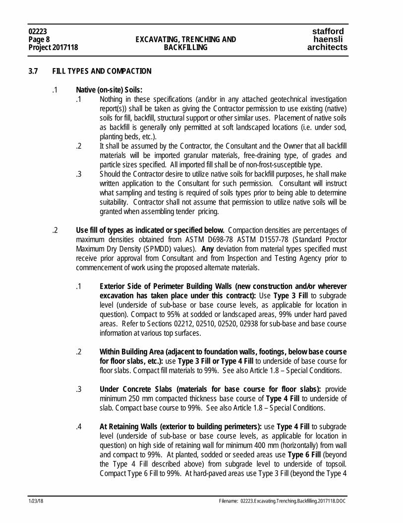
02223 stafford Page 8 EXCAVATING, TRENCHING AND haensli Project 2017118 BACKFILLING architects
1/23/18 Filename: 02223.Excavating.Trenching.Backfilling.2017118.DOC
3.7 FILL TYPES AND COMPACTION
.1 Native (on-site) Soils: .1 Nothing in these specifications (and/or in any attached geotechnical investigation
report(s)) shall be taken as giving the Contractor permission to use existing (native) soils for fill, backfill, structural support or other similar uses. Placement of native soils as backfill is generally only permitted at soft landscaped locations (i.e. under sod, planting beds, etc.).
.2 It shall be assumed by the Contractor, the Consultant and the Owner that all backfill materials will be imported granular materials, free-draining type, of grades and particle sizes specified. All imported fill shall be of non-frost-susceptible type.
.3 Should the Contractor desire to utilize native soils for backfill purposes, he shall make written application to the Consultant for such permission. Consultant will instruct what sampling and testing is required of soils types prior to being able to determine suitability. Contractor shall not assume that permission to utilize native soils will be granted when assembling tender pricing.
.2 Use fill of types as indicated or specified below. Compaction densities are percentages of
maximum densities obtained from ASTM D698-78 ASTM D1557-78 (Standard Proctor Maximum Dry Density (SPMDD) values). Any deviation from material types specified must receive prior approval from Consultant and from Inspection and Testing Agency prior to commencement of work using the proposed alternate materials. .1 Exterior Side of Perimeter Building Walls (new construction and/or wherever
excavation has taken place under this contract): Use Type 3 Fill to subgrade level (underside of sub-base or base course levels, as applicable for location in question). Compact to 95% at sodded or landscaped areas, 99% under hard paved areas. Refer to Sections 02212, 02510, 02520, 02938 for sub-base and base course information at various top surfaces.
.2 Within Building Area (adjacent to foundation walls, footings, below base course
for floor slabs, etc.): use Type 3 Fill or Type 4 Fill to underside of base course for floor slabs. Compact fill materials to 99%. See also Article 1.8 – Special Conditions.
.3 Under Concrete Slabs (materials for base course for floor slabs): provide
minimum 250 mm compacted thickness base course of Type 4 Fill to underside of slab. Compact base course to 99%. See also Article 1.8 – Special Conditions.
.4 At Retaining Walls (exterior to building perimeters): use Type 4 Fill to subgrade
level (underside of sub-base or base course levels, as applicable for location in question) on high side of retaining wall for minimum 400 mm (horizontally) from wall and compact to 99%. At planted, sodded or seeded areas use Type 6 Fill (beyond the Type 4 Fill described above) from subgrade level to underside of topsoil. Compact Type 6 Fill to 99%. At hard-paved areas use Type 3 Fill (beyond the Type 4
stafford 02223 haensli EXCAVATING, TRENCHING AND Page 9 architects BACKFILLING Project 2017118
Filename: 02223.Excavating.Trenching.Backfilling.2017118.DOC 1/23/18
Fill described above) from subgrade level to underside of base course for paving. Compact Type 3 Fill to 99%.
.5 At Weeping Tiles / Weepers (interior or exterior of building area): use Type 3
Fill from bottom of excavation to underside of weepers (minimum compacted thickness 150 mm) and compact to 99%. Provide Type 4 Fill at and around weepers – stone to extend a minimum of 150 mm beyond each side of intended weepers locations. Place weepers at proper locations on compacted fill with holes/slots faced down, taking care not to damage geotextile sleeve. Place Type 4 Fill around and over weepers, carefully compacting fill to avoid collapsing and/or damage to weepers. Type 4 Fill cover above top of weeper pipes to be minimum 150 mm deep compacted thickness when complete. Additional structural fill above this level shall be Type 3 Fill adjacent to foudation walls to a horizontal distance of 400 mm beyond outer face of foundation walls – fill beyond this horizontal distance may be Type 3 Fill or Type 4 Fill. Refer also to Section 02710 – Foundation and Underslab Drainage for additional and/or more specific requirements.
.6 Underground Services (Divisions 15 & 16 work):
.1 Divisions 15 and 16 are to be responsible for backfill and compaction at excavations related to work of those Divisions. Costs for this work are to be included in the bids for Division 15 and 16 as submitted in accordance with Document 00100 - Instructions to Tenderers. All backfilling and compaction operations performed by Division 15 and 16 are to be in accordance with the materials and methods requirements of this Section.
.2 All buried services piping and equipment to have adequate bedding and protection. Trenches to be excavated to 150mm (6 in.) below intended bottom of piping. Set piping and equipment in bedding layer, minimum 150mm thick, of clean, sharp sand (or Type 1 Fill if approved by Consultant). Bedding layer to be carefully formed, compacted to 98%, shaped to cradle piping up to horizontal centreline and provide continuous support. Backfill by hand (following approval of piping by Municipal Authorities) from top of bedding to 150mm (6 in.) above top of pipe for pipes up to 450mm (18 in) diameter; to 300mm (12 in) above top of pipe for larger diameter pipes. Compact by careful tamping in maximum 150mm (6 in.) lifts to minimum 99% SPMDD.
.3 Ensure that no debris or fill is permitted to enter piping. Protect all joints and connections throughout placement and backfill procedures. Provide concrete thrust blocks and backfill around manholes, catchbasins and other equipment concurrent with backfilling of piping. Do not allow piping or equipment to move or shift during backfill operations.

02223 stafford Page 10 EXCAVATING, TRENCHING AND haensli Project 2017118 BACKFILLING architects
1/23/18 Filename: 02223.Excavating.Trenching.Backfilling.2017118.DOC
.4 Backfill from top of protection fill specified in .2 above using fill types as follows: .1 Within building area: use Type 3 Fill or Type 4 Fill to underside of
base course for floor slabs. Compact to 99%. .2 Exterior to building - under hard paved areas: use Type 3 Fill or
Type 4 Fill to underside of sub-base course for paving. Compact to 99%.
.3 Exterior to building (but not within 1.5 metres of building face) - under sodded, seeded or landscaped areas ONLY: Use Type 2 Fill or Type 6 Fill to underside of topsoil. Compact to 99%. Within 1.5 metres of building face use Type 3 Fill or Type 4 Fill. Compact to 99%.
3.8 BACKFILLING
.1 Do not proceed with backfilling operations until Consultant and, where applicable, the Municipal Authority having jurisdiction has inspected and approved installations.
.2 Areas to be backfilled to be free from debris, snow, ice, water and frozen ground. .3 Do not use backfill material which is frozen or contains ice, snow or debris. .4 Backfilling around installations:
.1 Place bedding and surround material as specified elsewhere.
.2 Do not backfill around or over cast-in-place concrete within 24 hours after placing.
.3 Place layers simultaneously on both sides of installed work to equalize loading. Difference not to exceed 600 mm.
.4 Where temporary unbalanced earth pressures are liable to develop on walls or other structures: .1 Permit concrete to cure for minimum 14 days or until it has sufficient strength
to withstand earth and compaction pressure and approval obtained from Consultant or:
.2 If approved by Consultant erect bracing or shoring to counteract unbalance, and leave in place until removal is approved by Consultant.
.5 Place material by hand under, around and over installations until 600 mm of cover is
provided. Dumping material directly on installations will not be permitted. .6 Install drainage/filter system in backfill as indicated or directed by Consultant. .7 Place backfill material in uniform layers not exceeding 200 mm compacted thickness up to
grades indicated. Compact each layer before placing succeeding layer.
stafford 02223 haensli EXCAVATING, TRENCHING AND Page 11 architects BACKFILLING Project 2017118
Filename: 02223.Excavating.Trenching.Backfilling.2017118.DOC 1/23/18
3.9 INSPECTION AND TESTING
.1 Testing of materials and compaction will be carried out by testing laboratory designated by
Consultant. Frequency of tests will be determined by Consultant and Contractor. .2 Costs of testing will be paid for from Cash Allowance as specified in Section 01020 -
Allowances. Refer to Section 01410 - Testing Laboratory Services. 3.10 RESTORATION
.1 Upon completion of work, remove surplus materials and debris, trim slopes, and correct
defects noted by Consultant. Clean and reinstate areas affected by work as directed by Consultant.
END OF SECTION 02223
02223 stafford Page 12 EXCAVATING, TRENCHING AND haensli Project 2017118 BACKFILLING architects
1/23/18 Filename: 02223.Excavating.Trenching.Backfilling.2017118.DOC
This Page is Intentionally Left Blank
stafford 03000 haensli DIVISION 3: CONCRETE WORK Page 1 architects Project 2017118
Filename: 03000.Div03.Concrete.Work.2017118.doc 1/23/18
1 General 1.1 RELATED WORK .1 Section 02223 – Excavating, Trencing and Backfilling (backfilling below base course beneath
slabs and behind walls) .2 Section 04000 – Masonry Work (grouting beneath base plates bearing on masonry) 1.2 CODES AND STANDARDS - GENERAL .1 Comply with the requirements of the Ontario Building Code, the Occupational Health and
Safety Act, and Regulations for Construction Projects, all to latest edition and amendments. .2 All materials and methods of construction shall conform to CAN/CSA A23.1-M, unless
otherwise noted. .3 Before the start of Work, provide the following references in the Project Field Office:
.1 CAN/CSA A23.1-M and CAN/CSA A23.2-M .2 Reinforcing Steel Institute of Canada - Manual of Standard Practice .3 ACI Guide to Cast-in-Place Architectural Concrete Practice .4 ACI Standard 347 - Recommended Practice for Concrete Formwork
.4 Referenced documents shall be editions designated in Section 2.6 of the Ontario Building
Code. 1.3 MINIMUM CONCRETE STRENGTH AND ADMIXTURE STANDARDS .1 Minimum concrete strength at any location on this project shall be 25 MPa. Any
strengths/standards mentioned and/or listed in specifications or on drawings which are greater and/or more stringent than those stated above shall govern.
.2 All concrete which shall be exposed to exterior conditions in finished locations shall include air
entrainment admixtures to provide minimum 6% entrained air. Any air entrainment standards mentioned and/or listed in specifications or on drawings which are greater and/or more stringent than those stated above shall govern.
.3 The use of special mixes and/or special admixtures to facilitate proper placement of concrete
in specific locations shall be reviewed on a location-by-location basis. Consultant will review the special conditions or requirements of unusual pour conditions. Use of special mixes and/or admixtures for Contractor’s schedule requirements and/or general convenience shall not constitute legitimate grounds for extra payment(s).
.4 The use of “low MPa concrete”, “backfill concrete” or similar materials are generally
acceptable for backfill conditions (in place of granular fill types specified elsewhere), where use of such materials is warranted by construction conditions. Review and gain approval of Consultant prior to placing of “backfill concrete” or similar.
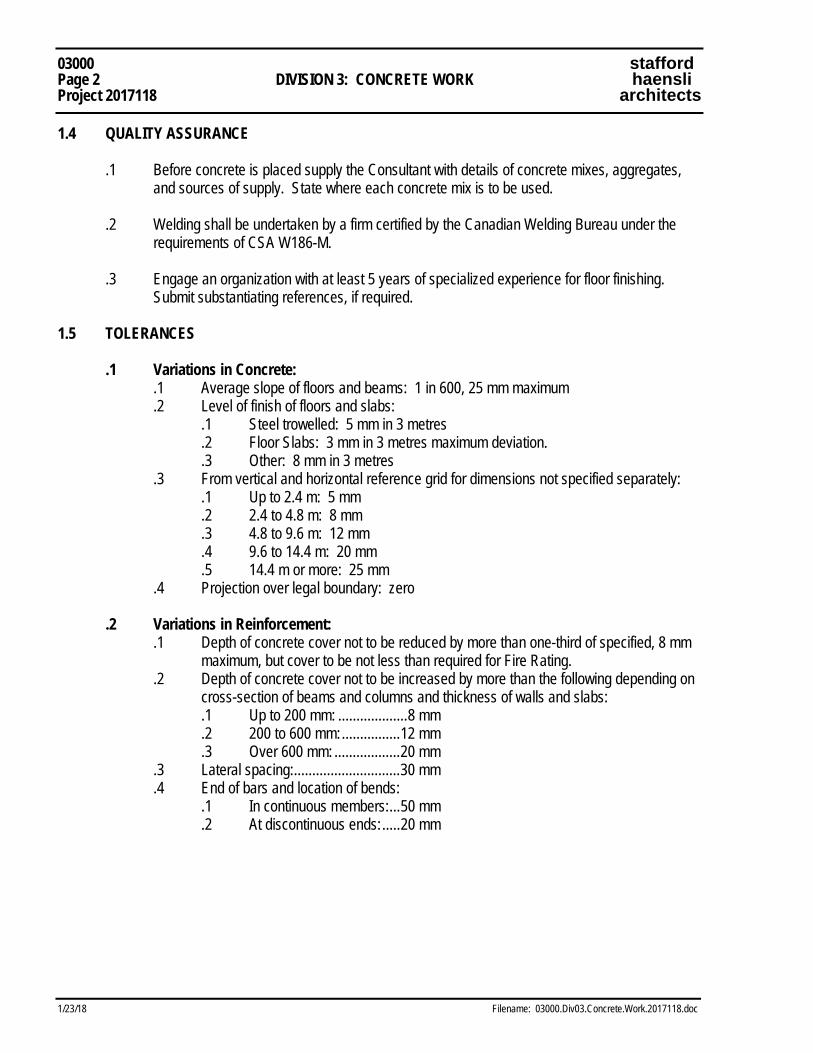
03000 stafford Page 2 DIVISION 3: CONCRETE WORK haensli Project 2017118 architects
1/23/18 Filename: 03000.Div03.Concrete.Work.2017118.doc
1.4 QUALITY ASSURANCE .1 Before concrete is placed supply the Consultant with details of concrete mixes, aggregates,
and sources of supply. State where each concrete mix is to be used. .2 Welding shall be undertaken by a firm certified by the Canadian Welding Bureau under the
requirements of CSA W186-M. .3 Engage an organization with at least 5 years of specialized experience for floor finishing.
Submit substantiating references, if required. 1.5 TOLERANCES .1 Variations in Concrete:
.1 Average slope of floors and beams: 1 in 600, 25 mm maximum .2 Level of finish of floors and slabs:
.1 Steel trowelled: 5 mm in 3 metres .2 Floor Slabs: 3 mm in 3 metres maximum deviation. .3 Other: 8 mm in 3 metres
.3 From vertical and horizontal reference grid for dimensions not specified separately: .1 Up to 2.4 m: 5 mm .2 2.4 to 4.8 m: 8 mm .3 4.8 to 9.6 m: 12 mm .4 9.6 to 14.4 m: 20 mm .5 14.4 m or more: 25 mm
.4 Projection over legal boundary: zero .2 Variations in Reinforcement:
.1 Depth of concrete cover not to be reduced by more than one-third of specified, 8 mm maximum, but cover to be not less than required for Fire Rating.
.2 Depth of concrete cover not to be increased by more than the following depending on cross-section of beams and columns and thickness of walls and slabs:
.1 Up to 200 mm: ................... 8 mm .2 200 to 600 mm: ................ 12 mm .3 Over 600 mm: .................. 20 mm
.3 Lateral spacing: ............................. 30 mm .4 End of bars and location of bends:
.1 In continuous members: ... 50 mm .2 At discontinuous ends: ..... 20 mm
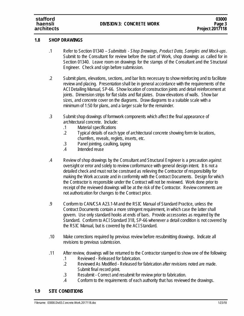
stafford 03000 haensli DIVISION 3: CONCRETE WORK Page 3 architects Project 2017118
Filename: 03000.Div03.Concrete.Work.2017118.doc 1/23/18
1.8 SHOP DRAWINGS .1 Refer to Section 01340 – Submittals - Shop Drawings, Product Data, Samples and Mock-ups.
Submit to the Consultant for review before the start of Work, shop drawings as called for in Section 01340. Leave room on drawings for the stamps of the Consultant and the Structural Engineer. Check and sign before submission.
.2 Submit plans, elevations, sections, and bar lists necessary to show reinforcing and to facilitate
review and placing. Presentation shall be in general accordance with the requirements of the ACI Detailing Manual, SP-66. Show location of construction joints and detail reinforcement at joints. Dimension strips for flat slabs and flat plates. Draw elevations of walls. Show bar sizes, and concrete cover on the diagrams. Draw diagrams to a suitable scale with a minimum of 1:50 for plans, and a larger scale for the remainder.
.3 Submit shop drawings of formwork components which affect the final appearance of
architectural concrete. Include: .1 Material specifications .2 Typical details of each type of architectural concrete showing form tie locations,
chamfers, reveals, reglets, inserts, etc. .3 Panel jointing, caulking, taping .4 Intended reuse
.4 Review of shop drawings by the Consultant and Structural Engineer is a precaution against
oversight or error and solely to review conformance with general design intent. It is not a detailed check and must not be construed as relieving the Contractor of responsibility for making the Work accurate and in conformity with the Contract Documents. Design for which the Contractor is responsible under the Contract will not be reviewed. Work done prior to receipt of the reviewed drawings will be at the risk of the Contractor. Review comments are not authorization for changes to the Contract price.
.9 Conform to CAN/CSA A23.1-M and the RSIC Manual of Standard Practice, unless the
Contract Documents contain a more stringent requirement, in which case the latter shall govern. Use only standard hooks at ends of bars. Provide accessories as required by the Standard. Conform to ACI Standard 318, SP-66 whenever a detail condition is not covered by the RSIC Manual, but is covered by the ACI Standard.
.10 Make corrections required by previous review before resubmitting drawings. Indicate all
revisions to previous submission. .11 After review, drawings will be returned to the Contractor stamped to show one of the following:
.1 Reviewed - Released for fabrication. .2 Reviewed As Modified - Released for fabrication after revisions noted are made.
Submit final record print. .3 Resubmit - Correct and resubmit for review prior to fabrication. .4 Conform to the requirements of each authority that has reviewed the drawings.
1.9 SITE CONDITIONS
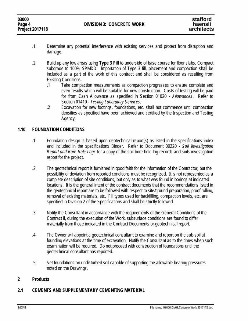
03000 stafford Page 4 DIVISION 3: CONCRETE WORK haensli Project 2017118 architects
1/23/18 Filename: 03000.Div03.Concrete.Work.2017118.doc
.1 Determine any potential interference with existing services and protect from disruption and
damage. .2 Build up any low areas using Type 3 Fill to underside of base course for floor slabs. Compact
subgrade to 100% SPMDD. Importation of Type 3 fill, placement and compaction shall be included as a part of the work of this contract and shall be considered as resulting from Existing Conditions.
.1 Take compaction measurements as compaction progresses to ensure complete and even results which will be suitable for new construction. Costs of testing will be paid for from Cash Allowance as specified in Section 01020 - Allowances. Refer to Section 01410 - Testing Laboratory Services.
.2 Excavation for new footings, foundations, etc. shall not commence until compaction densities as specified have been achieved and certified by the Inspection and Testing Agency.
1.10 FOUNDATION CONDITIONS .1 Foundation design is based upon geotechnical report(s) as listed in the specifications index
and included in the specifications Binder. Refer to Document 00220 - Soil Investigation Report and Bore Hole Logs for a copy of the soil bore hole log records and soils investigation report for the project.
.2 The geotechnical report is furnished in good faith for the information of the Contractor, but the
possibility of deviation from reported conditions must be recognized. It is not represented as a complete description of site conditions, but only as to what was found in borings at indicated locations. It is the general intent of the contract documents that the recommendations listed in the geotechnical report are to be followed with respect to site/ground preparation, proof rolling, removal of existing materials, etc. Fill types used for backfilling, compaction levels, etc. are specified in Division 2 of the Specifications and shall be strictly followed.
.3 Notify the Consultant in accordance with the requirements of the General Conditions of the
Contract if, during the execution of the Work, subsurface conditions are found to differ materially from those indicated in the Contract Documents or geotechnical report.
.4 The Owner will appoint a geotechnical consultant to examine and report on the sub-soil at
founding elevations at the time of excavation. Notify the Consultant as to the times when such examination will be required. Do not proceed with construction of foundations until the geotechnical consultant has reported.
.5 Set foundations on undisturbed soil capable of supporting the allowable bearing pressures
noted on the Drawings. 2 Products 2.1 CEMENTS AND SUPPLEMENTARY CEMENTING MATERIAL
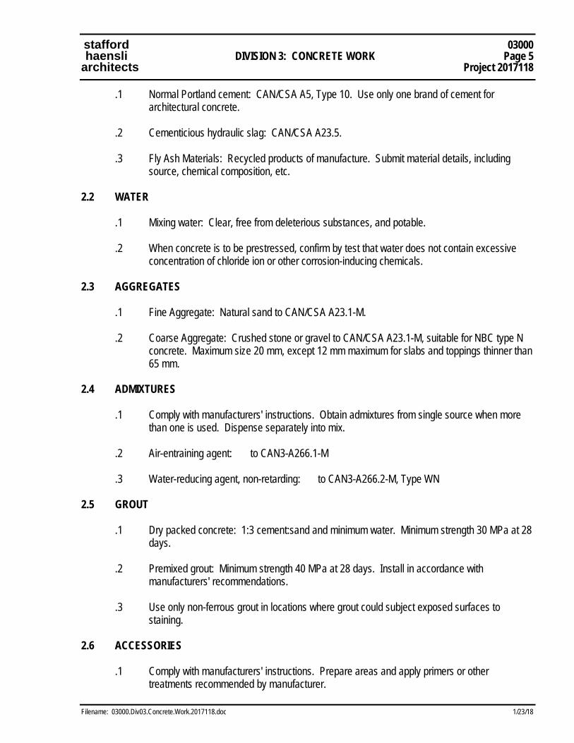
stafford 03000 haensli DIVISION 3: CONCRETE WORK Page 5 architects Project 2017118
Filename: 03000.Div03.Concrete.Work.2017118.doc 1/23/18
.1 Normal Portland cement: CAN/CSA A5, Type 10. Use only one brand of cement for architectural concrete.
.2 Cementicious hydraulic slag: CAN/CSA A23.5. .3 Fly Ash Materials: Recycled products of manufacture. Submit material details, including
source, chemical composition, etc. 2.2 WATER .1 Mixing water: Clear, free from deleterious substances, and potable. .2 When concrete is to be prestressed, confirm by test that water does not contain excessive
concentration of chloride ion or other corrosion-inducing chemicals. 2.3 AGGREGATES .1 Fine Aggregate: Natural sand to CAN/CSA A23.1-M. .2 Coarse Aggregate: Crushed stone or gravel to CAN/CSA A23.1-M, suitable for NBC type N
concrete. Maximum size 20 mm, except 12 mm maximum for slabs and toppings thinner than 65 mm.
2.4 ADMIXTURES .1 Comply with manufacturers' instructions. Obtain admixtures from single source when more
than one is used. Dispense separately into mix. .2 Air-entraining agent: to CAN3-A266.1-M .3 Water-reducing agent, non-retarding: to CAN3-A266.2-M, Type WN 2.5 GROUT .1 Dry packed concrete: 1:3 cement:sand and minimum water. Minimum strength 30 MPa at 28
days. .2 Premixed grout: Minimum strength 40 MPa at 28 days. Install in accordance with
manufacturers' recommendations. .3 Use only non-ferrous grout in locations where grout could subject exposed surfaces to
staining. 2.6 ACCESSORIES .1 Comply with manufacturers' instructions. Prepare areas and apply primers or other
treatments recommended by manufacturer.
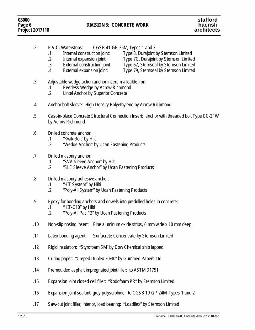
03000 stafford Page 6 DIVISION 3: CONCRETE WORK haensli Project 2017118 architects
1/23/18 Filename: 03000.Div03.Concrete.Work.2017118.doc
.2 P.V.C. Waterstops: CGSB 41-GP-35M, Types 1 and 3
.1 Internal construction joint: Type 3, Durajoint by Sternson Limited
.2 Internal expansion joint: Type 7C, Durajoint by Sternson Limited
.3 External construction joint: Type 67, Sternseal by Sternson Limited
.4 External expansion joint: Type 79, Sternseal by Sternson Limited .3 Adjustable wedge action anchor insert, malleable iron:
.1 Peerless Wedge by Acrow-Richmond .2 Lintel Anchor by Superior Concrete
.4 Anchor bolt sleeve: High-Density Polyethylene by Acrow-Richmond .5 Cast-in-place Concrete Structural Connection Insert: anchor with threaded bolt Type EC-2FW
by Acrow-Richmond .6 Drilled concrete anchor:
.1 “Kwik-Bolt” by Hilti .2 “Wedge Anchor” by Ucan Fastening Products
.7 Drilled masonry anchor: .1 “SVA Sleeve Anchor” by Hilti .2 “SLE Sleeve Anchor” by Ucan Fastening Products .8 Drilled masonry adhesive anchor:
.1 “HIT System” by Hilti .2 “Poly-All System” by Ucan Fastening Products
.9 Epoxy for bonding anchors and dowels into predrilled holes in concrete:
.1 “HIT-C10” by Hilti .2 “Poly-All Pac 12” by Ucan Fastening Products
.10 Non-slip nosing insert: Fine aluminum oxide strips, 6 mm wide x 10 mm deep .11 Latex bonding agent: Surfacrete Concentrate by Sternson Limited .12 Rigid insulation: “Styrofoam SM” by Dow Chemical ship lapped .13 Curing paper: “Creped Duplex 30/30” by Gummed Papers Ltd. .14 Premoulded asphalt impregnated joint filler: to ASTM D1751 .15 Expansion joint closed cell filler: “Rodofoam PR” by Sternson Limited .16 Expansion joint sealant, grey polysulphide: to CGSB 19-GP-24M, Types 1 and 2 .17 Saw-cut joint filler, interior, load bearing: “Loadflex” by Sternson Limited
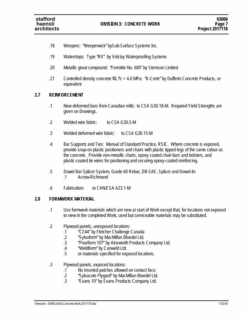
stafford 03000 haensli DIVISION 3: CONCRETE WORK Page 7 architects Project 2017118
Filename: 03000.Div03.Concrete.Work.2017118.doc 1/23/18
.18 Weepers: “Weeperwick” bySub-Surface Systems Inc. .19 Waterstops: Type “RX” by Volclay Waterproofing Systems .20 Metallic grout compound: “Ferrotite No. 600” by Sternson Limited .21 Controlled density concrete fill, f'c = 4.0 MPa: “K-Crete” by Dufferin Concrete Products, or
equivalent 2.7 REINFORCEMENT .1 New deformed bars from Canadian mills: to CSA G30.18-M. Required Yield Strengths are
given on Drawings. .2 Welded wire fabric: to CSA G30.5-M .3 Welded deformed wire fabric: to CSA G30.15-M
.4 Bar Supports and Ties: Manual of Standard Practice, RSIC. Where concrete is exposed,
provide snap-on plastic positioners and chairs with plastic tipped legs of the same colour as the concrete. Provide non-metallic chairs, epoxy coated chair-bars and bolsters, and plastic-coated tie wires for positioning and securing epoxy-coated reinforcing.
.5 Dowel Bar Splicer System, Grade 60 Rebar, DB-SAE, Splicer and Dowel-In: .1 Acrow-Richmond .6 Fabrication: to CAN/CSA A23.1-M 2.8 FORMWORK MATERIAL .1 Use formwork materials which are new at start of Work except that, for locations not exposed
to view in the completed Work, used but serviceable materials may be substituted. .2 Plywood panels, unexposed locations:
.1 “CZ44” by Fletcher Challenge Canada .2 “Sylvaform” by MacMillan Bloedel Ltd. .3 “Pourform 107” by Ainsworth Products Company Ltd. .4 “Weldform” by Canweld Ltd. .5 or materials specified for exposed locations.
.3 Plywood panels, exposed locations:
.1 No inserted patches allowed on contact face. .2 “Sylvacote Plygard” by MacMillan Bloedel Ltd. .3 “Evans 10” by Evans Products Company Ltd.
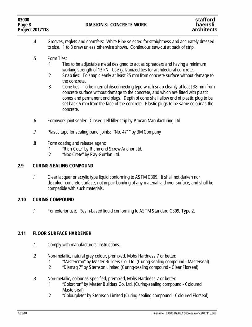
03000 stafford Page 8 DIVISION 3: CONCRETE WORK haensli Project 2017118 architects
1/23/18 Filename: 03000.Div03.Concrete.Work.2017118.doc
.4 Grooves, reglets and chamfers: White Pine selected for straightness and accurately dressed to size. 1 to 3 draw unless otherwise shown. Continuous saw-cut at back of strip.
.5 Form Ties:
.1 Ties to be adjustable metal designed to act as spreaders and having a minimum working strength of 13 kN. Use galvanized ties for architectural concrete.
.2 Snap ties: To snap cleanly at least 25 mm from concrete surface without damage to the concrete.
.3 Cone ties: To be internal disconnecting type which snap cleanly at least 38 mm from concrete surface without damage to the concrete, and which are fitted with plastic cones and permanent end plugs. Depth of cone shall allow end of plastic plug to be set back 6 mm from the face of the concrete. Plastic plugs to be same colour as the concrete.
.6 Formwork joint sealer: Closed-cell filler strip by Procan Manufacturing Ltd. .7 Plastic tape for sealing panel joints: “No. 471” by 3M Company .8 Form coating and release agent:
.1 “Rich-Cote” by Richmond Screw Anchor Ltd. .2 “Nox-Crete” by Ray-Gordon Ltd.
2.9 CURING-SEALING COMPOUND .1 Clear lacquer or acrylic type liquid conforming to ASTM C309. It shall not darken nor
discolour concrete surface, not impair bonding of any material laid over surface, and shall be compatible with such materials.
2.10 CURING COMPOUND .1 For exterior use. Resin-based liquid conforming to ASTM Standard C309, Type 2. 2.11 FLOOR SURFACE HARDENER .1 Comply with manufacturers' instructions. .2 Non-metallic, natural grey colour, premixed, Mohs Hardness 7 or better:
.1 “Mastercron” by Master Builders Co. Ltd. (Curing-sealing compound - Masterseal) .2 “Diamag 7” by Sternson Limited (Curing-sealing compound - Clear Florseal)
.3 Non-metallic, colour as specified, premixed, Mohs Hardness 7 or better:
.1 “Colorcron” by Master Builders Co. Ltd. (Curing-sealing compound - Coloured Masterseal)
.2 “Colourplete” by Sternson Limited (Curing-sealing compound - Coloured Florseal)

stafford 03000 haensli DIVISION 3: CONCRETE WORK Page 9 architects Project 2017118
Filename: 03000.Div03.Concrete.Work.2017118.doc 1/23/18
.4 Metallic, natural grey, premixed: .1 “Ferroplete” by Sternson Limited (Curing-sealing compound - Clear Florseal)
2.12 PROPORTIONING OF CONCRETE .1 Conform to CAN/CSA A23.1-M, Sections 14 and 15. Select mix proportions to provide the
specified strength, workability, and durability, in accordance with Table 11, Alternative 1. (ZP) .2 Calcium chloride admixtures and chloride-based admixtures shall NOT be used. .3 Concrete subjected to freezing and thawing, but not exposed to de-icing chemicals:
.1 Slabs - Exposure Classification F-1 .2 Footings and Piers - Exposure Classification F-2
.4 Concrete exposed to de-icing chemicals:
.1 Reinforced concrete - Exposure Classification C-1 .2 Slabs-on-grade - Exposure Classification C-2
.5 Use a water-reducing agent in all concrete. .6 Obtain approval of the Consultant for the use of other admixtures prior to use. .7 Allowable Slumps:
.1 Toppings and pavements: 20 mm to 60 mm .2 Other concrete: 50 mm to 110 mm
.8 Conform to the directions of the slag manufacturer for the proportioning and mixing of
concrete containing cementitious hydraulic slag. 2.13 PRODUCTION OF CONCRETE .1 Use ready-mixed concrete. .2 Heat concrete and deliver at a temperature between +13oC and +27oC whenever outdoor
temperature is less than +5oC. 3 Execution 3.1 CONSTRUCTION REVIEW .1 General Review During Construction by the Consultant, and Structural Engineer, and the
services of the independent inspection and testing agencies appointed by the Owner, are undertaken so that the Owner may be informed in writing as to the quality of the Contractor's performance and for the protection of the Owner. They will be carried out by examination of representative samples of the Work.
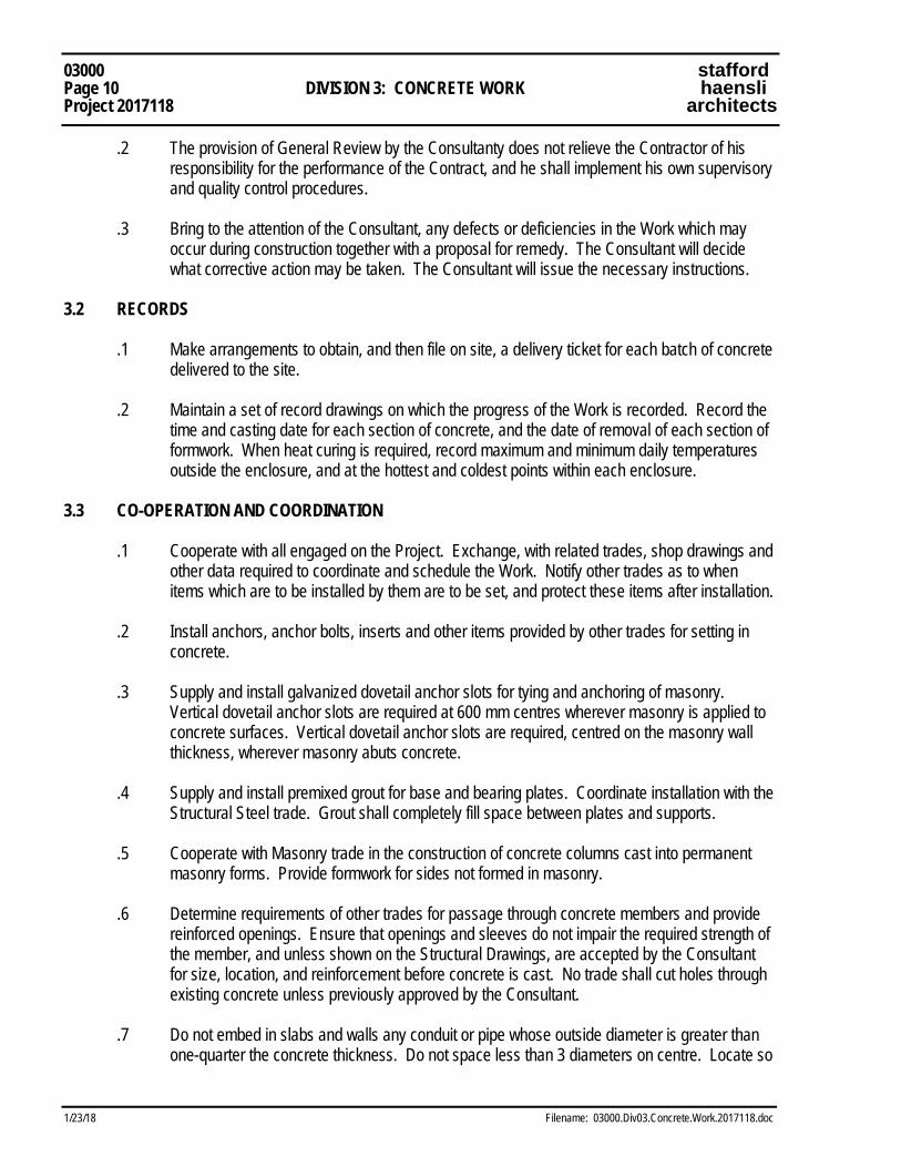
03000 stafford Page 10 DIVISION 3: CONCRETE WORK haensli Project 2017118 architects
1/23/18 Filename: 03000.Div03.Concrete.Work.2017118.doc
.2 The provision of General Review by the Consultanty does not relieve the Contractor of his responsibility for the performance of the Contract, and he shall implement his own supervisory and quality control procedures.
.3 Bring to the attention of the Consultant, any defects or deficiencies in the Work which may
occur during construction together with a proposal for remedy. The Consultant will decide what corrective action may be taken. The Consultant will issue the necessary instructions.
3.2 RECORDS .1 Make arrangements to obtain, and then file on site, a delivery ticket for each batch of concrete
delivered to the site. .2 Maintain a set of record drawings on which the progress of the Work is recorded. Record the
time and casting date for each section of concrete, and the date of removal of each section of formwork. When heat curing is required, record maximum and minimum daily temperatures outside the enclosure, and at the hottest and coldest points within each enclosure.
3.3 CO-OPERATION AND COORDINATION .1 Cooperate with all engaged on the Project. Exchange, with related trades, shop drawings and
other data required to coordinate and schedule the Work. Notify other trades as to when items which are to be installed by them are to be set, and protect these items after installation.
.2 Install anchors, anchor bolts, inserts and other items provided by other trades for setting in
concrete. .3 Supply and install galvanized dovetail anchor slots for tying and anchoring of masonry.
Vertical dovetail anchor slots are required at 600 mm centres wherever masonry is applied to concrete surfaces. Vertical dovetail anchor slots are required, centred on the masonry wall thickness, wherever masonry abuts concrete.
.4 Supply and install premixed grout for base and bearing plates. Coordinate installation with the
Structural Steel trade. Grout shall completely fill space between plates and supports. .5 Cooperate with Masonry trade in the construction of concrete columns cast into permanent
masonry forms. Provide formwork for sides not formed in masonry. .6 Determine requirements of other trades for passage through concrete members and provide
reinforced openings. Ensure that openings and sleeves do not impair the required strength of the member, and unless shown on the Structural Drawings, are accepted by the Consultant for size, location, and reinforcement before concrete is cast. No trade shall cut holes through existing concrete unless previously approved by the Consultant.
.7 Do not embed in slabs and walls any conduit or pipe whose outside diameter is greater than
one-quarter the concrete thickness. Do not space less than 3 diameters on centre. Locate so
stafford 03000 haensli DIVISION 3: CONCRETE WORK Page 11 architects Project 2017118
Filename: 03000.Div03.Concrete.Work.2017118.doc 1/23/18
as not to impair the required strength of the member. Do not install in columns, conduit which displaces more than 3 percent of the cross-section.
.8 Provide dowels from abutting concrete to all masonry walls reinforced with bars. .9 Provide 200 mm high reinforced concrete band courses in masonry walls near floor levels and
other levels for anchorage of elevator guides. Reinforce with 2 - 10M bars continuous. Coordinate with elevator supplier and provide masonry wall fill at required locations..
.10 Install concrete grout for hollow metal door frames which occur in concrete walls. .11 Provide seat angles for support of masonry lintels above openings adjacent to concrete walls
and columns. Unless otherwise noted on the Drawings, use 75 x 75 x 10 steel angles and connect vertical legs to concrete using two 12 mm diameter drilled concrete anchors. Length of seat to equal width of lintel minus 20 mm.
3.4 INSPECTION AND TESTING .1 The Owner will appoint an independent inspection and testing agency to undertake concrete
strength tests. .2 Costs of inspection and concrete strength tests to be paid from the Cash Allowance specified
in Section 01020 - Allowances. .3 Concrete slump tests and air tests will be carried out for each ready-mix truck. Concrete failing
to meet specifications will be rejected. .4 Laboratory curing and testing will be carried out in accordance with applicable CSA
Standards. The agency will report to the Consultant, with copies to the Structural Engineer, the Contractor, and the Municipal Authorities. Reports will be made on a form similar to Appendix B of CAN/CSA A23.2-M, stating the location of concrete to which tests relate, and commenting on abnormal results, and conditions. Include in the report the Contractor's mix design numbers.
.5 Strength Tests:
.1 Make test cylinders for standard concrete strength tests. One test is required for each 100 cubic metres, but not less than one test for each class of concrete placed each day. Store cylinders in metal lined curing boxes maintained at a temperature of +10oC until shipped to the testing laboratory. Store additional cylinder required for cold weather conditions adjacent to Work for 7 days.
.2 Provide a group of three cylinders for each standard strength test. One specimen will be tested at 7 days and two at 28 days.
.3 Provide one additional site-cured cylinder for testing at 7 days when concrete is placed under cold weather conditions.
.6 Air-Entrainment Tests:
03000 stafford Page 12 DIVISION 3: CONCRETE WORK haensli Project 2017118 architects
1/23/18 Filename: 03000.Div03.Concrete.Work.2017118.doc
.1 Conduct one standard air-entrainment test for each 50 cubic metres of air-entrained concrete or portion thereof placed each day.
3.5 REJECTED WORK .1 Where review reveals materials or workmanship which appear to have failed to meet the
specified quality or tolerances, the Consultant shall have the authority to order additional curing; to have tests made of in-situ concrete, concrete cores, reinforcement or other materials; to order a structural analysis of the existing elements, and to load test the structure. All such work will be carried out in order to assist in determining whether the structure may, in the opinion of the Consultant be accepted, with or without strengthening or modification. Testing shall meet the requirements of the Ontario Building Code. All expense incurred shall be chargeable to the Contractor regardless of the results.
3.6 QUALITY CONTROL ON SITE .1 Employ a competent technician to establish and maintain lines and levels. Report
immediately to the Consultant any field dimension which does not agree with drawing dimensions.
.2 Structural alignment reports:
.1 Carry out on-going checks of alignment and levels as the Work progresses, and submit a written report to the Consultant, signed by the Contractor, immediately after completion of concrete work at each level of the structure.
.2 The report shall include: .1 Alignment and level of perimeter slab edge. .2 Alignment of concrete core wall faces. .3 Alignment and dimensions of elevator hoistways. .4 Variations from plumb, alignment, and level of structural elements in excess
of specified tolerances. .5 Variations affecting structural steel and curtain wall connections. .6 Identification of variations which affect the work of other trades.
.3 Formwork:
.1 Do not close deep forms until reinforcement has been reviewed. Check elevations, camber, and plumbness of formwork continuously, during concreting and after, until initial set occurs using pre-installed tell-tale devices. When necessary make appropriate adjustments promptly. Report to the Consultant all adjustments made after initial set.
.4 Reinforcement:
.1 Ensure that reinforcement is kept free from dirt, grease, loose mill scale, and rust. Ensure that reinforcement is complete, adequately tied, and properly positioned for cover in advance of the time scheduled for casting concrete.
.5 Install thermometers for recording temperature when concrete is placed under cold weather or
hot weather conditions.
stafford 03000 haensli DIVISION 3: CONCRETE WORK Page 13 architects Project 2017118
Filename: 03000.Div03.Concrete.Work.2017118.doc 1/23/18
3.7 WORKMANSHIP .1 Proper workmanship is the most important element in the achievement of quality concrete.
Minimum requirement is conformity with CAN/CSA A23.1-M, but comply with the specific requirements of the Contract.
3.8 ARCHITECTURAL CONCRETE .1 Architectural concrete is concrete which will be permanently exposed to view in interior
finished areas and on the exterior of the structure. Final appearance is as important a factor as the engineering properties of the concrete and failure of the as-cast concrete to meet the required standard of appearance may be a cause for rejection.
.2 Ensure that exposed surfaces are dense, even, uniform in colour, texture and distribution of
exposed aggregate. They shall be free from defects such as honeycombing, voids, loss of fines, visible flow lines and cold joints. Defects of this nature shall be cause for rejection of the Work.
.3 Ensure that concrete members have sharp accurate definitions of corners, reglets, etc. and
are free from chips and spalls. .4 Protect finished Work from damage and staining during the construction period. Pay special
attention to the protection of projecting reinforcing at construction joints. 3.9 FORMWORK CONSTRUCTION .1 Construct formwork so as to achieve the quality of concrete surface specified. .2 Design formwork and falsework to support construction loads and fluid pressures without
overstressing the material and without excessive deflection. Conform to CSA S269.1 and CAN/CSA S269.3. Facing materials for architectural concrete and their supports shall not deflect more than 1/400th of the span under pressure from the concrete. Dimensions of completed elements shall not exceed specified tolerances. Provide positive means of adjustment to permit re-alignment or re-adjustment.
.3 Make panels forming the soffits of exposed slabs and wall faces as large as possible and
arrange symmetrically. Arrange joints on exposed beams symmetrically on the span. Joints in exposed columns shall be level from column to column and consistent with joints in other parts of the structure. In areas where the Drawings show exposed grooves, reglets or chamfers arrange for the joints between panels to be hidden by the strips placed in the formwork.
.4 Make forms tight and flush faced to prevent the leakage of mortar and the creation of
unspecified fins or panel outlines. Joints between panels used for architectural concrete shall be neatly sealed.
03000 stafford Page 14 DIVISION 3: CONCRETE WORK haensli Project 2017118 architects
1/23/18 Filename: 03000.Div03.Concrete.Work.2017118.doc
.5 Place 16 mm bevel strips at the exposed corners of members to form chamfers unless the architectural details show an alternative profile. When beams are supported on columns of the same width, the chamfer shall extend across the face of the column. Nails used in formwork for architectural concrete shall be galvanized.
.6 Do not permit loads from formwork to be transmitted to adjacent existing structure. .7 Apply a form coating and release agent uniformly to the contact surface of formwork panels
before reuse. Seal all lumber in forms for architectural concrete prior to use. .8 Forms for architectural concrete may only be reused on identical sections using the original tie
holes and if in the opinion of the Consultant they are suitable for reuse. .9 Use internal form ties. .10 Install tell-tale devices which can indicate movement of the formwork during concreting. .11 Reinforce top and bottom of circular fibre forms with a band of nylon reinforced plastic
adhesive tape or equivalent. Ensure that forms are not scratched by reinforcing or ties. Do not allow forms to become wet.
3.10 FORMWORK REMOVAL AND RESHORING .1 Be responsible for the safety of the structure before and after forms are removed. In no case
shall formwork and falsework be removed until members can support their own weight and superimposed construction loads without excessive stress, deflection or distortion.
.2 Use Loc-Test pullout inserts to determine in-place strength of concrete prior to removal of
formwork. Do not locate on Architecturally exposed surfaces. Retain a testing company to supply, locate and test the inserts in accordance with ASTM C900. Provide the Consultant with test results for his records.
.3 Formwork and falsework for suspended structures shall not be removed prior to the in-place
strength of the concrete reaching 75% of its specified 28 day strength. 3.11 JOINTS .1 Construction Joints:
.1 Provide construction joints where specified or shown on the drawings. Locate and make other joints so as not to impair the required strength of the structure. Joints are subject to the review of the Consultant.
.2 Unless otherwise shown, maximum distances between construction joints are: .1 Slabs-on-grade: 7 metres, or 20 metres with sawcut joints at 5 metre centres .3 Provide a bulkhead at all construction joints and add a continuous keyway at least 20
mm deep to bulkhead except for slabs 90 mm or thinner.

stafford 03000 haensli DIVISION 3: CONCRETE WORK Page 15 architects Project 2017118
Filename: 03000.Div03.Concrete.Work.2017118.doc 1/23/18
.4 Extend reinforcing through construction joints except for slabs-on-grade. Add dowels, if necessary to make total steel passing through bulkhead at least the equivalent of 10M at 400 mm centres each face. Embed dowels at least 500 mm on each side of joint.
.5 Allow a minimum of 24 hours between placing adjacent slab sections separated by construction joints. Allow a minimum of 4 hours between casting columns and walls and casting supported beams, slabs, drops, capitals, brackets and haunches.
.2 Isolation Joints:
.1 Provide 10 mm thick premoulded asphalt impregnated joint filler of the same depth as the thickness of the concrete wherever slabs-on-grade abut foundation walls, columns and piers. Omit if slab is chased or dowelled into structure.
.3 Saw-cut Joints:
.1 Saw-cut joints in slabs-on-grade should generally occur on column lines and on intermediate lines which result in panels of approximately square sections. Sections shall not exceed 5 m in length or width.
.2 Saw-cut 90 mm and thinner slabs cast over non-composite steel deck or as toppings into approximately square panels not exceeding 6 m in length or width. Do not saw-cut slabs over composite steel deck or composite steel beams.
.3 Make saw-cuts as soon as the concrete can be cleanly cut and before shrinkage cracks can form. Cuts shall be 5 mm wide x one-quarter the depth of slab deep for slabs-on-grade, and 20 mm deep for other slabs. Install a bond breaker tape at bottom of cut. Install joint filler for full depth of cut, not less than 28 days after casting. Joints shall be clean and dry when filled.
.4 Waterstops:
.1 Install waterstops in all expansion and construction joints in exterior walls, basement walls, slabs supporting earth, and other locations shown.
.2 Splice all sections of waterstops for continuity over the full length of runs. Use prefabricated splice sections where two runs intersect.
.3 Securely wire waterstops to reinforcing bars at 1 m maximum centres to keep them in alignment when concrete is placed.
3.12 PLACEMENT OF REINFORCING .1 Use only reviewed shop drawings and the Structural Drawings for placing of reinforcement.
Report discrepancies to the Consultant before proceeding. .2 Before placing, remove all loose scale, dirt, oil or other coatings which would reduce bond.
Place reinforcement within the specified tolerances and secure in position by the use of chairs, spacers and hangers. Tie securely together using annealed wire to prevent displacement during concrete placing and vibrating. Use non-corroding tie wire for architectural concrete. Turn the ends of ties towards the interior of the concrete.
03000 stafford Page 16 DIVISION 3: CONCRETE WORK haensli Project 2017118 architects
1/23/18 Filename: 03000.Div03.Concrete.Work.2017118.doc
.3 Position reinforcing for exposed concrete using snap-on plastic positioners and chairs with plastic tipped legs of the same colour as the concrete. Use concrete chairs for slabs-on-grade and footings.
.4 Lap end cross wires of welded wire mesh at least 200 mm. 3.13 PLACEMENT OF CONCRETE .1 Remove water from excavations before placing concrete therein. Clean all forms of debris
and deleterious materials before placing concrete. Vacuum clean formwork for architectural concrete and composite steel deck.
.2 Convey concrete from mixer to place of final deposit by methods which will prevent
segregation of materials and change of concrete qualities. Time for this operation shall not exceed 30 minutes. Deposit concrete as close as possible to its final position. Placing once started shall proceed as a continuous operation until the full section planned for concreting has been completed. Place concrete in layers of such thickness that no concrete will be deposited on concrete which has hardened sufficiently to cause planes of weakness or cold joints. Do not allow the free fall of concrete to exceed 1.5 m. Use properly designed chutes or elephant trunks for vertical elements.
.3 Place concrete slabs on steel deck by pumping. Do not allow concrete to build up at one
location to more than twice the slab thickness. .4 Consolidate concrete by suitable means during placing operations. Work thoroughly around
reinforcement and embedded items and into corners of forms eliminating all air and stone pockets. Ensure that sufficient workmen are on hand for this operation.
.5 Arrange to have reinforcing setters on hand as concrete is placed in order to make any last
minute adjustments that may be required. .6 Provide each crew with an adequate number of operating and back-up vibrators during the
placing of concrete. Commence vibration of each lift as soon as its depth reaches 300 mm. Do not allow vibrator to touch formwork. Apply systematically and at such spacing intervals that zones of influence overlap and the vibrator penetrates the previous lift.
.7 Use external form vibrators in the case of column and other thin sections where rodding,
spading and the use of internal vibrators is impractical. They shall be firmly fixed to the forms and so spaced that the complete lift of concrete is visibly affected. Platform and screed type vibrators may be used to ensure a dense top surface where this cannot be obtained by the use of internal equipment.
3.14 SLABS-ON-GRADE .1 See Drawings for thicknesses of concrete slabs-on-grade and slab reinforcing. Refer to
Structural and Architectural Drawings for slab depressions, slopes and finishes. For
stafford 03000 haensli DIVISION 3: CONCRETE WORK Page 17 architects Project 2017118
Filename: 03000.Div03.Concrete.Work.2017118.doc 1/23/18
dimensions and boundaries of affected areas refer to Architectural Drawings. Slope floors to drains where indicated.
3.15 SURFACE FINISHING .1 Patching:
.1 Patching of exposed concrete is not permitted without the acceptance of the Consultant. Patching prior to acceptance shall be grounds for rejection of the concrete. Where patching is accepted, the exposed patch shall be indistinguishable from the surrounding finish after both are dry. Determine patching mixes by trial batches. Perimeter of cut-out areas shall have edges which are perpendicular to the surface. Incorporate a liquid latex bonding agent into the mix. Just prior to application, coat the base surface with the bonding agent. Cure patches by keeping continuously moist for seven days.
.2 Form Ties:
.1 Break snap ties 38 mm deep from surface and fill voids with mortar which, in the case of exposed concrete, shall match surface in texture and colour. Incorporate a latex bonding agent into the mix.
.2 Disconnect threaded ties and plug holes with plastic plugs set 6 mm from concrete face with a latex bonding agent.
.3 Smooth Rubbed Finish:
.1 Produce finish on concrete no later than one day after forms removed. Wet surface and rub with carborundum brick until uniform colour and texture produced. Do not use a cement paste.
.4 Slabs:
.1 Cast slabs with a top surface that is level or sloping as required by the Drawings. Set top of slab below finished floor level by the distance required for the type of applied finish.
.2 Use experienced workmen to do consolidation and finishing. Ambient temperature shall not be less than +16oC. Do not start final finishing while there is excess moisture or bleed water on the surface.
.3 Provide final finish in accordance with proposed use. Refer to Room Schedule for floors.
.1 Screeded and bull floated: .1 Skim coats, pits
.2 Screeded, bull floated and scored with wire brush: .1 Base for mortar setting beds .2 Base for bonded toppings
.3 Powered float finish: .1 Slabs which receive a membrane .2 Roofs
.4 Powered steel trowel finish: .1 Interior exposed slabs
03000 stafford Page 18 DIVISION 3: CONCRETE WORK haensli Project 2017118 architects
1/23/18 Filename: 03000.Div03.Concrete.Work.2017118.doc
.2 Slabs which receive resilient flooring, carpet, epoxy-based finishes or thin-set tiles
.3 Future floors .4 Steel trowel exposed interior concrete floors at least twice.
.5 Preparation for Applied Finishes:
.1 When concrete surface is to receive a surface applied treatment, it shall be cleaned and prepared as necessary to receive the treatment. Acid etch and wash the surface, if necessary, to provide the required degree of roughness for proper bond.
.6 Hardener:
.1 Apply non-metallic floor hardener to all concrete floor slabs which are not listed to receive finished flooring (VCT, carpet, etc.).
.2 Apply at the rate of 5 to 7.5** kg of hardener per square metre in two separate shakes. Apply two-thirds of the total amount in the first application. Float then apply the remainder transverse to the first application. Steel trowel repeatedly to ensure maximum density.
** Diamag 7 rate: 5 to 7 kg/square metre Ferroplete rate: 5 to 7.5 kg/square metre 3.16 CURING AND PROTECTION .1 Beginning immediately after placement, protect concrete from premature drying, sunshine,
excessively hot or cold temperatures, and mechanical injury. Maintain at a relatively constant temperature for as long as is required for hydration of the cement and curing of the concrete. Provide adequate moisture under dry conditions by wetting subgrade and surrounding construction as appropriate.
.2 Minimize moisture loss from surfaces placed against wooden forms, or plastic and metal
forms exposed to heating by the sun, by keeping the forms wet until they can be safely removed. If forms are removed in less than 7 days, curing shall be continued by one of the wet curing methods specified for surfaces not in contact with forms.
.3 Select curing methods best suited to the ambient conditions in which the structure is being
constructed but use wet curing methods only in the following cases: .1 Air temperature exceeds +25oC. .2 There is a risk of shrinkage and cracking of concrete surfaces due to the estimated
evaporation exceeding 0.5 kg of water per square metre per hour. .3 Floor surfaces to receive concrete toppings, epoxy-based finishes, thin set ceramic
tile or chemical composition flooring. .4 Cure concrete surfaces not in contact with forms by one of the following methods:
.1 Ponding or continuous sprinkling. .2 Application of absorptive covering kept continuously wet. .3 Application of fog spray followed by a covering of curing paper lapped 150 mm and
held down at all edges. .4 Application of a curing-sealing compound, where permitted, immediately after
disappearance of surface water sheen. Do not use a compound unless it is
stafford 03000 haensli DIVISION 3: CONCRETE WORK Page 19 architects Project 2017118
Filename: 03000.Div03.Concrete.Work.2017118.doc 1/23/18
compatible with any material which may be applied to or laid over the concrete surface.
.5 Curing methods based upon keeping surfaces wet shall continue for at least 7 days. Prevent intermittent drying of surfaces.
.5 When exposed concrete floors or carpeted floors are specified and wet curing is used, apply
one coat of a curing-sealing compound at the end of the wet curing period and a final coat prior to occupancy.
3.17 HOT WEATHER CONCRETING .1 Comply with the requirements of CAN/CSA A23.1-M. Take the necessary precautions
whenever the air temperature exceeds +25oC or the rate of evaporation approaches 0.5 kg per square metre per hour. Make preparations in advance of placing concrete.
3.18 COLD WEATHER CONCRETING .1 Provide on site and ready for operation between at least October 15th and April 30th,
temporary plant and equipment for heating materials and forms and for maintaining the proper temperature and humidity of the concrete during curing. Consult CAN/CSA A23.1-M and comply with its requirements.
.2 Ensure that the surface on which finished slabs and toppings are placed, including soil, is at a
temperature of at least +13oC. Ensure that any surface against which other concrete is to be placed, including soil, is at a temperature of at least +5oC.
3.19 PITS, CURBS, BASES .1 Construct all concrete sumps, pits, trenches, curbs, and machinery bases forming part of floor
construction that are required within the building by other trades. .2 Reinforce bases with 10M at 300 each way, top and bottom, plus 1 - 10M perimeter bar top
and bottom. 3.20 REINFORCED MASONRY .1 Supply concrete and reinforcing bars required by the Masonry trade for the construction of
lintels, walls, and piers. Note that grout for filling masonry is supplied by Masonry trade. Note that Structural Drawings do not show all openings. Refer to lintel notes on these Drawings.
3.21 DRILLED ANCHORS .1 Conform to requirements of manufacturer. . .2 Retain an inspection and testing company to randomly select and pull test 5% of all anchors
installed on a weekly basis. Pull test to twice the design tension capacity of the anchor given
03000 stafford Page 20 DIVISION 3: CONCRETE WORK haensli Project 2017118 architects
1/23/18 Filename: 03000.Div03.Concrete.Work.2017118.doc
by the manufacturer. Submit reports to Consultant within one week of testing. Notify Consultant immediately if any anchor fails the pull test.
3.22 SEALER .1 Apply sealer to exposed surface of curbs and paving, in two coats, in accordance with
manufacturer’s direction. Prevent contamination of adjacent surfaces. END OF SECTION 03000
stafford 03345 haensli CONCRETE FLOOR FINISHES Page 1 architects Project 2017118
Filename: 03345.ConcreteFloorFin.2017118.DOC 1/23/18
1 General 1.1 RELATED WORK .1 Section 03300 - Cast-In-Place Concrete 1.2 REFERENCE STANDARDS .1 Do concrete floor finishing work in accordance with CAN/CSA-A23.1 except where specified
otherwise. .2 Where there are differences between the specifications and drawings and the codes,
standards or acts, the most stringent shall govern. 1.3 TOLERANCES .1 Perform finishing operations so that completed work will be in accordance with requirements
set out in CAN/CSA-A23.1 and as listed below: .2 Level of finish of floors and slabs: .1 Steel trowelled (general locations): 5 mm in 3 m .2 Other: 8 mm in 3 m
.2 These tolerances are acceptable with regard to visual and structural requirements.
Interfacing tolerances may not be compatible with the above. Review and coordinate interfacing tolerances so that the various elements come together properly.
.3 Note the need for accurate alignment of perimeter slab edges both horizontally and vertically. 1.4 WARRANTY .1 Floors: .1 The warranty as specified in Article GC 12.3 - Warranty of CCDC Document No. 2,
2008 shall be extended to two (2) years from the date of Substantial Performance for the work of this Section.
.2 The Contractor hereby warrants all floor surfaces finished under this Section for a
period of two years against dusting, disintegrating and/or other defects within the control of the Contractor.

03345 stafford Page 2 CONCRETE FLOOR FINISHES haensli Project 2017118 architects
1/23/18 Filename: 03345.ConcreteFloorFin.2017118.DOC
1.5 SUBMITTALS .1 Cambers .1 Submit a proposal for review by the Consultant as to how the specified camber in
slabs and beams are to be achieved.
2 Products 2.1 MATERIALS .1 Concrete Materials: to Section 03300 - Cast-in-Place Concrete. .2 Bonding Agent: epoxy based bonding agent for areas requiring repairs or two layer
applications of concrete materials. .1 Acceptable Material: "Bonding Agent ST-432" as manufactured by Sternson Limited
or approved equal by Master Builders Technologies. .3 Mortar/Grout Admixture: latex based bonding admixture for mortar and/or grout when being
applied into saw-cuts, etc. .1 Acceptable Material: "Sterncrete Liquid" as manufactured by Sternson Limited or
approved equal by Master Builders Technologies. .4 Concrete Curing/Sealing Agent: penetrating concrete floor sealer and curing agent, applied
to assist proper curing of concrete and to seal top surface against dusting and staining. To be applied to all concrete floor areas except for hardened concrete (HDCONC).
.1 Acceptable material: "CC-392" as manufactured by Sternson Limited or approved equal by Master Builders Technologies.
.2 Application Rate: 7 sq. metre per litre (77 sq. ft. per litre) .5 Non-Metallic Floor Hardener (Standard Type): non-pigmented, natural grey colour,
premixed, Mohs Hardness 7 or better, medium duty, non-metallic aggregate hardener: .1 Acceptable Material: Mastercron - Master Builders Co. Ltd. (Curing-sealing
compound - Masterseal) .2 Acceptable Material: Diamag 7 - Sternson Limited (Curing-sealing compound - Clear
Florseal) .3 Application Rate: 7 kg. per sq. metre (143 lbs. per sq. ft.)
stafford 03345 haensli CONCRETE FLOOR FINISHES Page 3 architects Project 2017118
Filename: 03345.ConcreteFloorFin.2017118.DOC 1/23/18
.7 Concrete Curing/Sealing/Finishing Agent (Hardened Concrete Floors - Pigmented and Non-Pigmented: penetrating concrete floor sealer and curing agent, applied to assist proper curing of concrete and to seal top surface against dusting and staining. To be applied to all concrete floor areas of hardened concrete (HDCONC). Use pigmented type to match colour of floor; use clear type at non-pigmented floors.
.1 Acceptable material: "Florseal W.B." as manufactured by Sternson Limited or approved equal by Master Builders Technologies.
.2 Application Rate: 8 sq. metres per litre for curing/sealing, 10 sq. metres per litre for resealing.
.8 Wax: clear or coloured concrete floor buffing compound (as applicable for specific floor areas. .1 Acceptable Material: "Florseal Colorhard" floor wax as manufactured by Sternson,
colour to match pigment of floor, clear at non-pigmented floors. .2 Application Rate: as recommended by manufacturer. .9 Use compatible additives, admixtures and hardeners. 3 Execution 3.1 GENERAL .1 Conform to CAN/CSA-A23.1 .2 Finish the top or final surface of concrete by screeding, floating and trowelling as defined in
CSA/CAN-A23.1 and in accordance with the architectural final finish requirements. Unless specified otherwise, steel trowel to CAN/CSA-A23.1-M90. Use final "spin-trowel" methods at floors designated to be non-slip.
.3 Verify floor finish tolerances and cambers after each slab has been cast and before any
formwork has been removed. For beams measure along their centre lines. For slab measure along grid and centre lines as well as at all column locations (or core walls). Measuring points to include the point of maximum camber and shall be no further than 3000 mm apart.
.4 Survey floors including beams three weeks after all shoring has been removed. Measure
along same points as in clause 3.1.3 above. .5 Use suitable techniques to finish abutting pours at joints to eliminate "humping". If humping
occurs, grind the joint down level to the surrounding surface. .6 Where the finish is not of the quality specified, remove ridges, undulations, projections at
construction joints and areas of carbonation and scaling by methods approved by Consultant. 3.2 FLOOR FINISH
03345 stafford Page 4 CONCRETE FLOOR FINISHES haensli Project 2017118 architects
1/23/18 Filename: 03345.ConcreteFloorFin.2017118.DOC
.1 Finish concrete in accordance with CAN/CSA-A23.1 Class A to smooth, steel trowel finish
using powered float/trowel equipment (except for non-slip floors which are to have final "spin-trowel' finish.
.2 Do not sprinkle dry cement or dry cement and sand mixture over concrete surfaces. .3 All concrete floors shall be given two coats of concrete floor curing/sealing agent. First coat
of sealer shall be applied either diluted or full strength depending upon product and manufacturer's printed instructions. Allow first application to dry thoroughly and then apply second coat of sealer at full strength.
.4 As late as possible, prior to turning the building over to the Owner, clean down concrete to
remove surface discolourations, efflorecence and the like. Use a suitable cleaning agent which will not itself stain the surface or mar the texture through chemical reaction.
.5 Apply non-metallic floor hardener to all concrete floor slabs which are not listed to receive
finished flooring (VCT, carpet, etc.) and to all floors and areas noted as hardened concrete (HDCONC or HDC) on Room Finish Schedule. Cure to manufacturer's recommendations. Applications rates to be as specified in 2.1 above.
.6 Apply sealing agent to all areas of hardened concrete; application and curing to
manufacturer's recommendations. .7 Apply concrete floor wax in accordance with manufacturer's instructions. .8 Cure concrete in accordance with CAN/CSA-A23.1-M90 except where specified otherwise. 3.3 CRACK REPAIR .1 Prior to completion of the project an in any case not sooner than 28 days after concrete has
been placed, examine concrete floor surfaces and repair all major cracks in them. Rout cracks out with mechanical router to 13 mm square approximate cross section. Then clean and fill cracks in same manner as saw-cuts in slab on grade.
stafford 03345 haensli CONCRETE FLOOR FINISHES Page 5 architects Project 2017118
Filename: 03345.ConcreteFloorFin.2017118.DOC 1/23/18
3.4 TOPPINGS .1 Conform to requirements of CSA/CAN-A23.1 for bonded toppings and the following: .1 Set rigid screeds accurately by transit level to provide level or sloped floors as
required. "Wet" screed methods will not be permitted. .2 Bring base to same temperature as surrounding atmosphere before placing topping.
Minimum temperature shall be 10 degrees C. .3 Apply bonding agent to sustrate prior to placing topping materials. Apply bonding
agent in accordance with manufacturer's instructions. 3.5 JOINTS IN SLABS ON GRADE .1 Where slabs abut adjacent construction, provide layer of joint filler between. .2 Saw-cut slabs on grade exposed to view in the finished building into panels as indicated with
a maximum length between saw-cuts of 6m. Arrange panels as shown or to the Consultant's approval.
.3 Carry out cutting in accordance with recommendations contained in ACI 302 but in any event
between 6 and 18 hours after placement of concrete. .4 After a period of at least 28 days, fill saw-cuts with mortar containing cement, sand and latex
bonding agent. Ensure that joints to be filled are clean, dry and free of foreign matter. .5 Construction joints may be provided in slabs on grade so that pours on any one day may be
kept to reasonable sizes. Locate construction joints to the Consultant's approval. .6 In exposed concrete, provide a reglet at construction joints of the approximate width of a saw-
cut and fill the reglet as specified for saw-cuts. END OF SECTION 03345
03345 stafford Page 6 CONCRETE FLOOR FINISHES haensli Project 2017118 architects
1/23/18 Filename: 03345.ConcreteFloorFin.2017118.DOC
This Page Is Left Blank Intentionally

stafford 05130 haensli STRUCTURAL STEEL & Page 1 architects STEEL DECK Project 2017118
Filename: 05130.Struct.Steel.and.Deck.2017118.doc 1/23/18
1 General 1.1 RELATED WORK .1 Related Work Provided or Performed by Other Sections: .1 Section 03000 – Concrete Work - Grouting under base plates and bearing plates. .2 Section 05500 - Metal Fabrications - erection of loose lintels, beams, shelf angles and wall
plates. .3 Section 09910 – Painting and Special Coatings – field (finished) painting of steel .2 Work Furnished But Not Installed: .1 Anchor bolts .2 Connection assemblies set in concrete .3 Loose beams, lintels, and shelf angles .4 Continuous plates or angles on walls for support of joists and deck .3 Work Furnished and Installed: .1 Separate column base plates .2 Columns, beams, purlins, and girts .3 Steel joists and steel bridging .4 Bracing .5 Steel framing around roof openings .6 Diagonal supports at columns for deck or slabs .7 Expansion joint material .8 Field connections to concrete .9 Structural steel for alterations to existing structure 1.2 DESCRIPTION
.1 Architectural, Structural, Mechanical and Electrical Drawings: Examine all tender drawings and other documents for an appreciation of the extent and complexity of the structural steelwork required. The Structural drawings show member sizes, and location and extent in general. See Architectural drawings for precise configurations and location and extent of steel members which relate to architectural requirements, and see Mechanical and Electrical drawings for their requirements affecting Structural steelwork.
.2 Work of this Section includes all structural steel work required and shown on the structural
drawings. Steel members and sections are shown on the Architectural drawings – steel members shown on Architectural drawings which are not identified on Structural drawings are assumed to be supplied by Section 05500 – Metal Fabrications.
05130 stafford Page 2 STRUCTURAL STEEL & haensli Project 2017118 STEEL DECK architects
1/23/18 Filename: 05130.Struct.Steel.and.Deck.2017118.doc
1.3 REFERENCES .1 Standards are referenced thus in this Section: STANDARD ABBREVIATION CAN/CSA G40.21-M92 ........................... CAN/CSA G40.21-M CAN/CSA G164-M92 .............................. CAN/CSA G164 CAN/CSA S16.1-M89 .............................. CAN/CSA S16.1-M CAN/CSA S136-M89 ............................... CAN/CSA S136-M CSA W47.1-1983 .................................... CSA W47.1 CSA W48.1-M1991 ................................. CSA W48.1-M CSA W59-M1989 .................................... CSA W59 CGSB 1-GP-140M-1978 ......................... CGSB 1-GP-140M CGSB 1-GP-171M .................................. CGSB 1-GP-171M CISC/CPMA 1-73a .................................. CISC/CPMA 1-73a CISC/CPMA 2-75 .................................... CISC/CPMA 2-75 ASTM A53-90 ASTM A53 ASTM A108-89a ..................................... ASTM A108 ASTM A307-89 ASTM A307 ASTM A325M-89 .................................... ASTM A325M ASTM A446M-87 .................................... ASTM A446M 1.4 QUALITY ASSURANCE
.1 Supplier / Fabricator to be Member of CISC: Work shall be carried out by a structural steel fabricator who is a member of the Canadian Institute of Steel Construction (CISC), or by a fabricator that has been accepted by the Consultant in writing prior to the close of bidding. Refer to CISC website for a current list of members.
.2 Engage a Professional Engineer to be responsible for the design, detailing and installation of
all connections related to structural steelwork. Before submitting shop drawings, submit a letter signed and sealed by that Engineer stating that he has been engaged to undertake the responsibility for the above. When requested, submit calculations signed and sealed by that Engineer. On completion of erection, submit a letter signed and sealed by that Engineer to certify that Work has been completed in accordance with all shop drawings reviewed by the Consultant and the Structural Engineer.
.3 Welding shall be performed by a firm certified by the Canadian Welding Bureau under the
requirements of CSA W47.1, Division 1 or 2.1. .4 Before the start of fabrication, supply the Consultant and the independent inspection agency
with mill test reports properly correlated to the materials. The onus for proving the properties of the steel supplied rests with the Contractor.
stafford 05130 haensli STRUCTURAL STEEL & Page 3 architects STEEL DECK Project 2017118
Filename: 05130.Struct.Steel.and.Deck.2017118.doc 1/23/18
.5 Do not splice sections without the prior acceptance of the Consultant and the submission of pertinent shop drawings. Accepted splices will be required to develop the section. Each splice shall be given a non-destructive test by an independent inspection company acceptable to the Consultant. Testing shall be at the Contractor's expense. Evaluate results in accordance with CSA W59 and report to the Consultant.
1.5 TOLERANCES
.1 Conform to the fabrication and erection tolerances of CAN/CSA S16.1-M. .2 In addition if more stringent tolerances are specified elsewhere to suit interfacing materials,
the latter shall govern in such cases. 1.6 SHOP DRAWINGS
.1 Refer to Section 01340 - Shop Drawings, Product Data, Samples and Mock-ups. "Shop Drawings" means erection diagrams and shop details.
.2 Submit to the Consultant for review before fabrication, one sepia print and 2 white prints of
erection diagrams. Leave room on drawings for the stamps of the Consultant and the Structural Engineer. Check and sign before submission. Only the sepia will be returned.
.3 Submit to the Consultant, before fabrication, two record copies of shop details. Check and
sign before submission. .4 All shop drawings shall bear the seal and signature of the Professional Engineer responsible
for designing the connections. .5 Provide final record prints after all corrections are made. .6 It is advisable to submit erection diagrams for review before preparing shop details. Include
details of special conditions. Make erection diagrams.
.7 If required, CAD diskettes of the structural drawings may be available, from the Structural Consultant, in accordance with the provisions of Section 01120 – Electronic Communications and Data Files. These files, if available, would be for use in the preparation of shop drawings only.
.8 Show on drawings: material specifications, section splices, types of shop and field
connections, net weld lengths, and the seal and signature of the Professional Engineer who has designed the connections. Show precautions which will be taken to exclude threads from shear planes of bearing type bolted connections.
.9 Show in addition for steel joists: joint details, section splices, bridging, loadings for each joist,
and the seal and signature of the Professional Engineer who has designed joists.
05130 stafford Page 4 STRUCTURAL STEEL & haensli Project 2017118 STEEL DECK architects
1/23/18 Filename: 05130.Struct.Steel.and.Deck.2017118.doc
.10 Review of shop drawings by the Consultant and Structural Engineer is a precaution against oversight or error and solely to review conformance with general design intent. It is not a detailed check and must not be construed as relieving the Contractor of responsibility for making the Work accurate and in conformity with the Contract Documents. Design for which the Contractor is responsible under the Contract will not be reviewed. Work done prior to the receipt of the reviewed drawings will be at the risk of the Contractor. Review comments are not authorization for changes to the Contract price.
.11 Provide the office preparing shop drawings with a complete set of Contract Drawings and
Specifications plus all Addenda and Change Orders. .12 Do not release column shop details for fabrication before establishing on site the final
elevations of the tops of supporting piers. .13 Make corrections required by previous review before resubmitting drawings. Clearly indicate
all changes and additions to previous submission. Do not add new details to drawings which have been stamped as reviewed or noted.
.14 After review, erection diagrams will be returned to the Contractor stamped to show one of the
following: .1 Reviewed - Reviewed with no comments. .2 Noted - Reviewed with comments noted on drawing. Submit two final record prints. .3 Resubmit - Reviewed with comments noted on drawing. Correct and resubmit for
review. .4 Conform to the requirements of each authority that has reviewed the drawings.
.15 Allow at least 15 Working Days for drawing review by the Structural Engineer when preparing
the Project Schedule. Allow more time when large quantities of shop drawings are submitted. Submit in general conformity with the sequence of construction intended. Co-ordinate with the Consultant.
.16 Keep on site at all times a set of shop drawings bearing the reviewal stamps of the Consultant
and the Structural Engineer and use only these drawings and the Structural Drawings to erect structural steel. Neatly mark on the Structural Drawings changes issued during the course of construction.
.17 Show details by which steel assemblies, which are set in concrete, are to be connected to the
formwork.

stafford 05130 haensli STRUCTURAL STEEL & Page 5 architects STEEL DECK Project 2017118
Filename: 05130.Struct.Steel.and.Deck.2017118.doc 1/23/18
1.7 SUBSTITUTIONS
.1 Submit all proposals for substitutions to the Consultant in writing in advance of shop drawings. Identify each item clearly. Do not proceed with a proposed change unless it is accepted in writing.
.2 Substitution of alternative sections will be allowed provided the new members have equal or
greater capacity and stiffness and are of dimensions acceptable at proposed locations. 1.8 SITE CONDITIONS
.1 Determine any potential interference with existing services and protect from disruption and damage.
1.9 UNIT PRICES
.1 Unit prices are not required to be submitted for Work of this Section.
2 Products 2.1 MATERIALS
.1 Rolled shapes and plates: CAN/CSA G40.21-M, Grade 350W with the following exceptions: .1 Atmospheric corrosion resisting steel: CAN/CSA G40.21-M, Grade 350A .2 Hollow structural sections: CAN/CSA G40.21-M, Grade 350W, Class H .3 Cold formed shapes: ASTM A446M, Grade D, Fy = 345 MPa, except no underrun in
thickness allowed .2 Steel joists: CAN/CSA G40.21-M or CAN/CSA S136-M .3 Welded wide flange shapes: Manufactured by Algoma Steel Corp. Ltd. CAN/CSA
G40.21-M, Grade 350W. .4 Steel and Metal Deck Products: .1 Deck: ASTM A653/A653M, Grade 230, Zinc-Iron Alloy (Galvanized) Coating Z275
or ASTM A792/A792M, Grade 230, Aluminum-Zinc Alloy Coating AZ150 (to equivalent coating thickness comparable to Z275 galvanizing for roof). or ASTM A792/A792M, Grade 230, Aluminum-Zinc Alloy Coating AZ150 (to equivalent coating thickness comparable to Z075 galvanizing for Floor).
.2 Zinc-Rich Paint: CGSB 1-GP-171M

05130 stafford Page 6 STRUCTURAL STEEL & haensli Project 2017118 STEEL DECK architects
1/23/18 Filename: 05130.Struct.Steel.and.Deck.2017118.doc
.3 Glass Fibre Insulation: Density 0.17 kN per cubic metre, shaped to profiles of flutes.
.4 Neoprene Closures: Rubatex closed cell neoprene EPT compressed, Grade
R483T. .5 Acoustic Deck: Metal deck as specified in item 2.1.1 above plus matrix of perforated
holes in vertical legs of formed deck profiles. Supply pre-formed fiberglass acoustical strips to fit into deck flutes. Supply strips to General Contractor – these will be installed by Division 7 as part of roofing operations. Refer to drawings for locations and extents.
.5 Arc welding electrodes and equipment: CSA W48.1-M Electrode Classification Number: E480XX .6 Machine bolts: ASTM A307 High-strength bolts: ASTM A325M and CAN/CSA S16.1-M
.1 Bolts shall be identifiable by their head markings and galvanized whenever used to connect members which are galvanized or painted with zinc-rich paint.
.7 Anchor bolts: CAN/CSA G40.21-M, Grade 260W .8 Concrete anchor studs, headed: ASTM A108, Grades 1015 and 1018Fy = 345 MPa .9 Cast-in-place concrete Structural Connection Insert anchor with threaded bolt:
.1 Type EC-2FW - Acrow-Richmond .10 Drilled concrete anchor:
.1 Kwik-Bolt - Hilti Wedge Anchor - Ucan Fastening Products .11 Drilled masonry anchor:
.1 SVA Sleeve Anchor - Hilti SLE Sleeve Anchor - Ucan Fastening Products .12 Joint filler for exposed steelwork: Epoxy resin .13 Shop primer paint: (for steel without finish coat)
.1 No lead-based paints allowed.
.2 CISC/CPMA 1-73a .14 Zinc-rich shop primer paint: CGSB 1-GP-171M .15 Galvanizing: CAN/CSA G164-M .16 Sliding bearing assembly in protective bag (Teflon/neoprene/ stainless steel):
.1 Fabreeka Canada Ltd.,
.2 Structural Tech Corp. Ltd.
stafford 05130 haensli STRUCTURAL STEEL & Page 7 architects STEEL DECK Project 2017118
Filename: 05130.Struct.Steel.and.Deck.2017118.doc 1/23/18
2.2 CONNECTIONS
.1 Design connections to conform to CAN/CSA S16.1-M. Conform also to the C.I.S.C. Handbook of Steel Construction, except as otherwise required by the specifications.
.2 Retain a Professional Engineer to be responsible for the design of all connections. .3 In general, make shop and field connections with high-strength bolts or by welding. Use
machine bolts only for secondary connections. .4 Pretension all high-strength bolts used in:
.1 Wind bracing connections;
.2 connections where bolts are subject to tensile loadings;
.3 connections using oversized or slotted holes unless finger-tight bolts are required to accomodate movement; and
.4 connections required by CAN/CSA S16.1-M to be pretensioned.
.5 Use double angle headers or end connection plates whenever possible. Do not use single angle headers for beams greater than 530 mm deep. Make minimum depth of headers and end plates one-half the beam depth. Provide seated beam connections with top clip angles. Cantilevered plate connections will only be accepted for secondary members carrying minor loads. Provide all eccentrically loaded spandrel beams with top and bottom flange connections for torsional restraint.
.6 Provide connections designed for a pass-through force equal to the smaller axial force where
axial forces occur in beams framing in on opposite sides of a supporting member. Axial force is centred in smaller beam if beam sizes differ.
.7 Install web and flange stiffener plates at moment connections as required by connection
design and detail but in every case when indicated on the drawings. If the shear generated in column web exceeds its shear capacity, reinforce the web.
.8 Provide at least one stiffener plate each side of web of beams continuous over columns
unless another type of stiffener is shown on the Drawings. .9 Provide moment connections at splices to maintain continuity of cranked beams. Provide
stiffener plates to resist unbalanced flange forces at splices. .10 Complete welded shop connections prior to galvanizing. .11 Detail and erect vertical diagonal bracing to provide a prestress of approximately 15 MPa. .12 Provide shelf angles and sash angles with adjustable bolted connections.

05130 stafford Page 8 STRUCTURAL STEEL & haensli Project 2017118 STEEL DECK architects
1/23/18 Filename: 05130.Struct.Steel.and.Deck.2017118.doc
.13 Where indicated on the drawings, connect to concrete using cast-in weld plates with headed stud anchors. Design and supply assemblies. Determine capacity of each anchor group considering edge distance, spacing and embedment.
2.3 STEEL JOISTS
.1 The Structural Drawings show the required depths of joists and their total loading including dead load, live load and self weight. Loading diagrams are given for non-uniform loads and additional point loads are noted where they occur. Apply live loads in accordance with requirements of CAN/CSA S16.1-M for special open-web steel joists. Comply with the recommendations for vibration control given in Appendix G of CAN/CSA S16.1-M.
.2 Total Floor load deflection shall not exceed 1/240th of the span and live load deflection
1/360th of the span. Total Roof load deflection shall not exceed 1/360th of the span and live load deflection
1/500th of the span. .3 All joist members and joints, shall be designed by a Professional Engineer.
.1 Joists supporting uniform loadings may be selected from standard loading tables prepared by the Professional Engineer but those supporting concentrated or other special loads shall be individually designed.
.2 In addition to uniform loadings, design joists for any concentrated loads resulting from piping 125 mm in diameter or larger which run parallel with the joists and for any other piping load of one kN or more.
.3 Both joists and joist bridging shall, in addition to the requirements of this Section, satisfy the requirements of any Fire Rated Assembly Design specified for the Project.
.4 On request, submit calculations and such further proof as is necessary to show that the joists conform to the requirements of the Specifications.
.5 All documents shall carry the seal and signature of the responsible Professional Engineer.
.4 Design and fabricate joists in accordance with CAN/CSA S16.1-M or CAN/CSA S136-M.
.1 Arrange members to form a statically determinate truss.
.2 Web and chord members shall have an axis of symmetry in the plane of the web.
.3 Minimum thickness of material shall be: flats and hot rolled sections 3 mm, rods 10 mm diameter, cold formed sections 2 mm.
.4 Make joists over 600 mm deep with a web system of vertical and diagonal members.
.5 Maximum slenderness ratio of tension web members of 1200 mm and deeper members shall be 240.
.6 Make all joists shoes with solid webs unless it can be shown by a fully documented analysis or a test program that an alternative shoe arrangement is satisfactory.
.7 Chord member splices when used shall be staggered and shown on the shop drawings.
.8 Welding at each splice shall develop the section.
.9 Retain an independent testing agency to visually check all chord splices. The agency shall also undertake non-destructive testing of those chord splices which occur in the
stafford 05130 haensli STRUCTURAL STEEL & Page 9 architects STEEL DECK Project 2017118
Filename: 05130.Struct.Steel.and.Deck.2017118.doc 1/23/18
middle half of the span and of each splice in web systems fabricated from bars. Arrange for the agency's reports to be reviewed by the Professional Engineer who has designed the joists and then submit these reports to the Consultant.
.5 Make joists which will be permanently exposed neat and uniform in appearance. The location
and appearance of splices must be acceptable to the Consultant. .6 Centre reaction point of joist framing from one side only over centroid of supporting beam.
Provide shoe depths required to suit the elevations of the joist bearing surfaces. .7 Arrange joists and bridging to accommodate recessed fixtures. Supply and install
supplementary framing for any openings between joists. Consult Mechanical Drawings for ductwork and supply special framed openings required between or within joists for its passage. Design joists for any concentrated loads resulting from such framing.
.8 Line up web members along joist runs sufficiently to permit mechanical services set within the
joist depths to be threaded through the joists. .9 Provide ceiling extensions where required. Attach suspended services using only clamps or
U-bolts. Do not cut or drill joist members. 2.4 FABRICATION
.1 Conform to CAN/CSA S16.1-M and CSA W59. .2 Orientate straight beams which have cambers within allowable mill tolerances so that the
resulting beam camber is up. .3 Increase thickness of curved sections at no extra cost where necessary to fabricate the
required curvature or fabricate curved sections from plates at no extra cost where necessary to accommodate the required curvature.
.4 No holes are permitted through webs of beams without the written permission / approval of the
Structural Engineer. Reinforce holes through webs of beams as instructed by Structural Engineer. Alternatively reinforcement may be designed in accordance with the procedure set forth in the CISC Handbook of Steel Construction provided calculations are submitted as part of the shop drawings.
.5 Provide weep holes at low point in all HSS sections which are not made watertight by
continuous welding in the shop. .6 Do not ship material to the site before it has been inspected.
2.5 PAINTING
.1 Clean steelwork prior to application of paint. Refer to CAN/CSA S16.1-M.

05130 stafford Page 10 STRUCTURAL STEEL & haensli Project 2017118 STEEL DECK architects
1/23/18 Filename: 05130.Struct.Steel.and.Deck.2017118.doc
.2 Apply paint under cover. Steel shall be dry when painted and paint shall be dry before loading
for shipment. .3 Apply zinc-rich primer paint not more than 24 hours after blast cleaning but prior to any visible
rust occurring on the surfaces. Do not apply when relative humidity exceeds 80%. Apply to achieve a dry film thickness of 0.08 mm.
.4 Apply one coat of shop primer paint to steelwork in the shop with the exception of:
.1 Galvanized members
.2 Members for which zinc-rich paint is specified
.3 Shear connectors and top flanges of composite beams
.4 Surfaces encased in or in contact with cast-in-place concrete including top flanges of beams supporting slabs
.5 Top flanges of composite beams with field welded shear connectors
.6 Surfaces and edges to be field welded for a distance of [50 mm]{2"} from the joint
.7 Contact surfaces of slip-resistant type joints assembled with high-strength bolts
.8 Surfaces fireproofed by spraying .5 Apply galvanizing to:
.1 ALL members which will be wholly or partially exposed to exterior elements (weather) in final location. This shall include members which are exposed to air cavities within exterior cavity walls. This shall also include members which are wholly or partially exposed above roofs.
.2 Lintels in exterior walls.
.6 When welding after galvanizing is in place, grind away galvanizing at areas to be welded. Touch up with two coats of zinc-rich paint.
.7 Apply primer paint to architecturally exposed surfaces without runs or sags. Sand down and
repaint areas not acceptable to the Consultant. .8 Apply touch-up paint after erection to all areas which have been missed, scraped or chipped
using the same paint as the shop coat or primer. .9 Apply two coats of zinc-rich touch-up paint to any galvanized surface which has been
damaged and which is accepted by the Consultant as being capable of repair without galvanizing.
.10 Clean and prepare surfaces of bolts which will receive a finished coat of paint in the same
manner as the connected steelwork. 2.6 LINTELS
.1 Structural Drawings do not show all lintels required. Refer to lintel notes on the Drawings.
stafford 05130 haensli STRUCTURAL STEEL & Page 11 architects STEEL DECK Project 2017118
Filename: 05130.Struct.Steel.and.Deck.2017118.doc 1/23/18
.2 Provide lintels with a minimum of 150 mm bearing at each end but not less than the depth of any specified bearing plate.
.3 Weld or bolt together multiple member lintels. Provide spacers if separated. If angle seats
are at different elevations provide steel packing. .4 Connect ends of suspended lintels to the structure and/or build into masonry to provide
adequate restraint. .5 Connect ends of steel lintels to columns where openings are adjacent to columns.
2.7 PLATES AND ANCHORS
.1 Provide beams and joists bearing on walls with bearing plates. .2 Provide beams and joists bearing on walls which continue above with standard wall anchors,
unless otherwise noted on the Drawings. .3 Anchor roof beams and joists to supporting walls with a minimum of two 16 mm diameter x
380 long anchor bolts, unless otherwise noted on the Drawings. .4 Weld beams and joists to bearing plates unless otherwise noted on the Drawings. .5 Where bearing plate sizes are not noted on the Drawings, design bearing plates for a
maximum factored bearing pressure of 1.5 MPa on masonry and 7.5 MPa on concrete. .6 Set beam bearing plates 10 mm back from edge of support. .7 Extend beams and joist shoes for full length of bearing plates.
2.8 SUPPORTS AT COLUMNS
.1 Provide diagonal or cantilevered angles at sides of columns where required for support of deck or slab.
.2 Provide seat angles for support of masonry lintels above openings adjacent to columns.
Unless otherwise noted on the Drawings, provide 75 x 75 x 10 steel angles attached to sides of columns. Length of seat to equal width of lintel minus 25 mm.
2.9 DECK DESIGN
.1 Design deck profiles for indicated loads in accordance with CAN/CSA S136-M. Section depths and minimum steel thicknesses are shown on the Drawings.
.2 Rib spacing, centre to centre, shall be 150 mm unless otherwise noted.
05130 stafford Page 12 STRUCTURAL STEEL & haensli Project 2017118 STEEL DECK architects
1/23/18 Filename: 05130.Struct.Steel.and.Deck.2017118.doc
.3 Deck profiles and welding shall, in addition to the requirements of this Section, satisfy the requirements of any Fire Rated Assembly Design specified for the Project.
.4 Limit deflection of roof deck under total load to 1/240th of span. .5 Limit deflection of floor deck under live load to 1/360th of span. .6 Limit long-term deflection of composite deck to 1/500th of span. .7 Make sections continuous over 3 spans or increase thickness of material to give the
equivalent stiffness and strength of a 3-span deck. .8 Design anchorage of roof deck to supports to resist net factored uplift forces of 3.3 kN per
square metre on cantilevers and at roof corners (3m x 3m areas) and 2.2 kN per square metre elsewhere, but not less than that shown on the drawings. Increase minimum welding specified under Erection if necessary.
.9 Provide side lap connections which distribute vertical loads between panels and also
horizontal loads when acting as a diaphragm.
2.10 DECK ACCESSORIES
.1 Provide all required closures, reinforcing sheet steel plates and flashing. .2 Reinforce edge of free spanning deck with channel shaped closure fitted to edge and welded
to deck. .3 Provide flashing at columns and points of discontinuity to prevent leakage of mortar when
concrete is placed over deck. .4 Provide edge forming for concrete slabs over deck. Weld to deck. .5 Provide and secure in place fitted steel closures to fill hollow spaces between webs
immediately above beams, partitions and walls transverse to deck when a ceiling is not specified. Where deck is continuous over support provide closures on each side and pack between closures with glass fibre insulation. Where deck span is parallel to walls and partitions, install steel flashings to provide a neat juncture.
.6 Provide both interior and exterior fitted steel closures where deck extends over exterior walls.
Pack between closures with glass fibre insulation. .7 Acoustical Strips for Acoustic Deck: Supply pre-formed fiberglass acoustical strips to fit into
deck flutes. Supply strips to General Contractor – these will be installed by Division 7 as part of roofing operations.
2.11 DECK OPENINGS
stafford 05130 haensli STRUCTURAL STEEL & Page 13 architects STEEL DECK Project 2017118
Filename: 05130.Struct.Steel.and.Deck.2017118.doc 1/23/18
.1 Structural Drawings do not show all openings required. Refer also to Architectural,
Mechanical, and Electrical Drawings. .2 Cut and reinforce openings indicated. .3 Openings up to 150 mm wide across the flutes require no reinforcing. .4 Reinforce roof openings 150 mm to 425 mm wide across the flutes. Use 50 x 50 x 5 angle
under the flutes at each end and extend across at least three flutes on each side. Tack weld angle to each flute with 25 mm tackwelds each side. Roof openings larger than 425 mm wide across the flutes will be framed by the Structural Steel trade.
.5 Reinforce openings through floor deck as specified for roofs but the maximum size of
reinforced openings shall be 300 mm x 300 mm. Larger openings will be framed by the Structural Steel trade. Minimum distance between unreinforced openings shall be 600 mm.
2.12 COMPOSITE DECK
.1 Provide data to substantiate the load capacity of deck when requested. Design shall have been undertaken by a Professional Engineer and load testing certified by an independent inspection agency.
.2 Form sections to produce section moduli and moments of inertia not less than those in the
published data of the manufacturer. Embossments shall ensure a composite unit of steel and concrete acting together to provide the required strength and stiffness.
.3 Design deck as a form to support the weight of the concrete when wet plus each of the
following construction loads applied separately: One kPa of uniform load, and 2 kN/m of transverse line load at centre of span applied over a width of 300 mm. Limit deflection to span/300. Allow for possibility that concrete may build up at any one location to twice the slab thickness during concrete placing operations.
3 Execution 3.1 CONSTRUCTION REVIEW
.1 General Review During Construction by the Consultant and Structural Engineer and the services of the independent inspection and testing agencies appointed by the Owner are undertaken so that the Owner may be informed as to the quality of the Contractor's performance and for the protection of the Owner. They will be carried out by examination of representative samples of the Work.
.2 The Contractor will receive copies of the construction review reports and the results of
material tests. He will thereby be informed of any defects or deficiencies found. The provision
05130 stafford Page 14 STRUCTURAL STEEL & haensli Project 2017118 STEEL DECK architects
1/23/18 Filename: 05130.Struct.Steel.and.Deck.2017118.doc
of this information does not relieve the Contractor of his responsibility for the performance of the Contract and he shall implement his own supervisory and quality control procedures.
.3 Bring to the attention of the Consultant and Structural Engineer any defects or deficiencies in
the Work which may occur during construction together with a proposal for remedy. The Structural Engineer will decide what corrective action may be taken. The Consultant will issue the necessary instructions.
3.2 CO-OPERATION
.1 Cooperate with all engaged on the Project. Exchange with related trades shop drawings and other data required to coordinate and schedule Work. Deliver material for installation by other trades when required.
.2 Provide where shown or required, holes and copings for connection and clearance of the
Work of other trades. Show on shop drawings before submitting for review. Holes in members shall not cause any appreciable reduction in strength.
.3 Do not cut holes in the field unless sizes and locations are accepted by the Consultant in each
case. Accepted field cutting and welding shall be undertaken by this Trade. .4 Supply and install framing around openings in steel floor deck greater than 300 mm across the
flutes and around openings in steel roof deck greater than 425 mm across the flutes. .5 Provide holes to receive 16 mm bolts for securing of any wood framing and blocking. Space
at 600 mm centres. Substitute 16 mm threaded studs with nuts in locations where appearance is a factor.
.6 Maintain horizontal bracing and its connections below the underside of the deck so as not to
interfere with the seating of the latter. 3.3 EXAMINATION OF WORK
.1 Do not begin operations before making a thorough examination of existing conditions and the Work of related trades. Report inconsistencies before proceeding.
3.4 INSPECTION AND TESTING
.1 Refer to Section 01410 – Testing Laboratory Services. .2 The Owner will appoint an independent inspection and testing agency. Notify the Consultant
two weeks in advance of the date when the first Work will be ready for inspection. .3 Pay for the cost of inspection from the Cash Allowance specified in Section 01020 –
Allowances.

stafford 05130 haensli STRUCTURAL STEEL & Page 15 architects STEEL DECK Project 2017118
Filename: 05130.Struct.Steel.and.Deck.2017118.doc 1/23/18
.4 Assist the agency in its work. Do not commence fabrication until details of inspection have been worked out with the inspection agency.
.5 Work will be inspected in the shop and when erected. Store fabricated members in the shop
so that they are accessible for inspection. .6 The inspection agency will submit reports to the Consultant, Structural Engineer, Contractor
and Municipal Authorities covering the Work inspected and provide details of errors or deficiencies observed.
.7 Inspection will include:
.1 Checking that mill test reports are properly correlated to materials
.2 Sampling fabrication and erection procedures for general conformity with the requirements of the Contract
.3 Checking welders' CWB Certification
.4 Checking fabricated members against specified member shapes
.5 Visual inspection of all welded connections including spot checking of joint preparation and fit up
.6 Sample checking bolted joints
.7 Sample checking composite studs
.8 Sample checking that tolerances are not exceeded during erection or during fit-up of field welded joints
.9 Inspection of field cutting
.10 Inspection of joist shoe bearing
.11 Inspection of sliding bearings
.12 Shop paint and field touch-up
.8 The inspector will undertake non-destructive testing of welding in a representative 10% of welded connections and of all butt welds in direct tension. Results will be evaluated in accordance with CSA W59.
.9 The inspector will check high-strength bolts in a representative 10% of bolted connections by
torque testing each bolt. He will torque test 10% of the remaining bolts at random, but not less than 2 bolts in each connection. He will remove nuts from 1% of all bearing bolts and check that thread is excluded from the shear planes.
3.5 FIELD MEASUREMENTS
.1 Make field measurements necessary to ensure the proper fit of members. .2 Identify on shop drawings dimensions which have been obtained by field measurement.
3.6 ERECTION – STRUCTURAL STEEL
.1 Comply with the requirements of CAN/CSA S16.1-M.

05130 stafford Page 16 STRUCTURAL STEEL & haensli Project 2017118 STEEL DECK architects
1/23/18 Filename: 05130.Struct.Steel.and.Deck.2017118.doc
.2 Submit a description of proposed erection methods and sequence to the Consultant for his records if requested.
.3 Make adequate provision for all loads acting on the structure during erection. Provide
temporary bracing to keep the structure stable, plumb and in true alignment during construction. Bracing members or connections shown on the Structural Drawings are those required for the completed structure, and may not be sufficient for erection purposes. Such additional temporary bracing as may be required is the responsibility of the Contractor.
.4 Set column base plates on levelling screws or on steel shims to the required elevation ready
for grouting. Remove shims after initial grouting and replace with grout. Levelling plates may be used under base plates not exceeding 0.1 square metres in area, provided the levelling plates are set with grout and are level to within 1.5 mm across the plate. Do not erect columns upon plates exceeding this tolerance. Lift base plates for inspection when so directed.
.5 Do not make permanent connections until as much of the structure as will be stiffened thereby
has been properly aligned. .6 Report ill-fitting connections to the Consultant before taking corrective measures. .7 Do not weld in an ambient temperature below -17oC. Preheat material adjacent to welding
areas when ambient temperature is between -17oC and +4oC. .8 Remove slag from all completed welds so that they may be visually inspected.
3.7 SUSPENDED LOADS
.1 Do not overstress members supporting suspended loads. Hanger loads shall not exceed 1 kN. Loads from mechanical and heavy electrical services suspended from the steelwork shall not exceed the load allowance provided for such services and shall be distributed uniformly.
.2 Prevent torsion from hangers connected to beams by alternating their positions on either side
of members. Do not apply twisting loads to joists and make attachment using only clamping devices or U-bolts. Loads shall only be suspended directly at the panel points of joists, unless the chords of the joists have been specifically designed to support the concentrated loads.
3.8 ERECTION – METAL DECK
.1 Carry out erection using only the forces of the steel deck fabricator unless written permission is obtained from the Consultant prior to the close of Bids to sublet the erection.
.2 Align deck end to end for accurate fit with corresponding sections. Ensure that sections are
parallel, even and straight.
stafford 05130 haensli STRUCTURAL STEEL & Page 17 architects STEEL DECK Project 2017118
Filename: 05130.Struct.Steel.and.Deck.2017118.doc 1/23/18
.3 Locate a rib of deck directly over steel beams spanning parallel to deck and at same elevation as deck support beams. Weld deck to beams as specified on Structural Drawings (weld types and spacings).
.4 Make end laps over supports lapping not less than 50 mm. Connect male and female side
laps by welding or mechanically interlocking at not more than 600 mm centres or as specified on the Structural Drawings, whichever is more stringent.
.5 Protect members supporting deck from damage when deck is being welded in place. Report
damage to the trade that has provided the member and establish with that trade a procedure for repair or replacement. Obtain the acceptance of the Consultant before starting remedial measures.
.6 Weld deck to steel supports at all bearing points with arc spot welds of 20 mm minimum
diameter in alternate flutes, unless otherwise noted on the Drawings. Stagger welds along flanges of supporting members to the maximum allowable by the width of the flange. Place one weld in each flute where side lap is made.
.7 Increase deck welding specified elsewhere if necessary to satisfy the requirements of any Fire
Rated Assembly Design specified for the Project. .8 Inspect all surfaces of deck after erection and touch-up with zinc-rich paint where protective
coating has been scratched or damaged. Minimum thickness 0.08 mm. .9 Where deck rests on exterior walls or spandrel beams, fill spaces between webs with
neoprene closures, top and bottom. .10 When flutes of deck run perpendicular to partitions which extend to underside of deck, fill
spaces between web with double run of neoprene closures on underside of deck. 3.9 REJECTED WORK
.1 Do not deliver to the site materials which are known not to meet the requirements of the Specifications. If rejected after delivery remove immediately from site.
.2 Where review reveals materials or workmanship which appear to have failed to meet the
specified quality or tolerances, the Consultant shall have the authority to order tests made of materials; to order detailed field surveys and measurements; to order a structural analysis of the existing elements and to load test the structure. All such Work will be carried out in order to assist in determining whether the structure may, in the opinion of the Consultant, be accepted, with or without strengthening or modification. Testing shall meet the requirements of the Ontario Building Code. All expense incurred shall be chargeable to the Contractor regardless of the results.
END OF SECTION 05130

05130 stafford Page 18 STRUCTURAL STEEL & haensli Project 2017118 STEEL DECK architects
1/23/18 Filename: 05130.Struct.Steel.and.Deck.2017118.doc
This page is left Intentionally Blank.
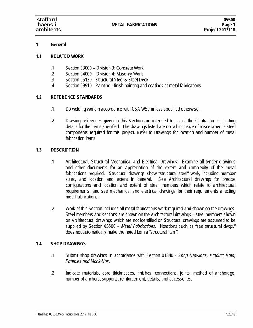
stafford 05500 haensli METAL FABRICATIONS Page 1 architects Project 2017118
Filename: 05500.MetalFabrications.2017118.DOC 1/23/18
1 General 1.1 RELATED WORK .1 Section 03000 – Division 3: Concrete Work .2 Section 04000 – Division 4: Masonry Work .3 Section 05130 - Structural Steel & Steel Deck .4 Section 09910 - Painting - finish painting and coatings at metal fabrications 1.2 REFERENCE STANDARDS .1 Do welding work in accordance with CSA W59 unless specified otherwise. .2 Drawing references given in this Section are intended to assist the Contractor in locating
details for the items specified. The drawings listed are not all inclusive of miscellaneous steel components required for this project. Refer to Drawings for location and number of metal fabrication items.
1.3 DESCRIPTION
.1 Architectural, Structural Mechanical and Electrical Drawings: Examine all tender drawings and other documents for an appreciation of the extent and complexity of the metal fabrications required. Structural drawings show “structural steel” work, including member sizes, and location and extent in general. See Architectural drawings for precise configurations and location and extent of steel members which relate to architectural requirements, and see mechanical and electrical drawings for their requirements affecting metal fabrications.
.2 Work of this Section includes all metal fabrications work required and shown on the drawings.
Steel members and sections are shown on the Architectural drawings – steel members shown on Architectural drawings which are not identified on Structural drawings are assumed to be supplied by Section 05500 – Metal Fabrications. Notations such as “see structural dwgs.” does not automatically make the noted item a “structural item”.
1.4 SHOP DRAWINGS .1 Submit shop drawings in accordance with Section 01340 - Shop Drawings, Product Data,
Samples and Mock-Ups. .2 Indicate materials, core thicknesses, finishes, connections, joints, method of anchorage,
number of anchors, supports, reinforcement, details, and accessories.
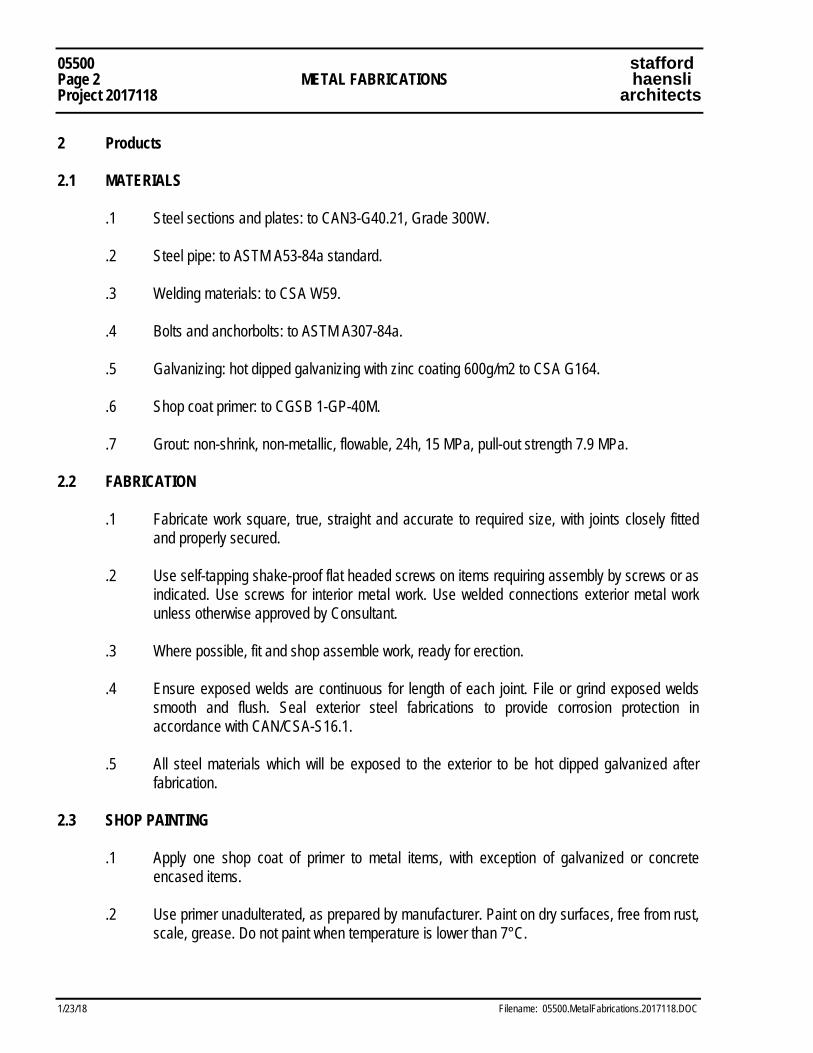
05500 stafford Page 2 METAL FABRICATIONS haensli Project 2017118 architects
1/23/18 Filename: 05500.MetalFabrications.2017118.DOC
2 Products 2.1 MATERIALS .1 Steel sections and plates: to CAN3-G40.21, Grade 300W. .2 Steel pipe: to ASTM A53-84a standard. .3 Welding materials: to CSA W59. .4 Bolts and anchorbolts: to ASTM A307-84a. .5 Galvanizing: hot dipped galvanizing with zinc coating 600g/m2 to CSA G164. .6 Shop coat primer: to CGSB 1-GP-40M. .7 Grout: non-shrink, non-metallic, flowable, 24h, 15 MPa, pull-out strength 7.9 MPa. 2.2 FABRICATION .1 Fabricate work square, true, straight and accurate to required size, with joints closely fitted
and properly secured. .2 Use self-tapping shake-proof flat headed screws on items requiring assembly by screws or as
indicated. Use screws for interior metal work. Use welded connections exterior metal work unless otherwise approved by Consultant.
.3 Where possible, fit and shop assemble work, ready for erection. .4 Ensure exposed welds are continuous for length of each joint. File or grind exposed welds
smooth and flush. Seal exterior steel fabrications to provide corrosion protection in accordance with CAN/CSA-S16.1.
.5 All steel materials which will be exposed to the exterior to be hot dipped galvanized after
fabrication. 2.3 SHOP PAINTING .1 Apply one shop coat of primer to metal items, with exception of galvanized or concrete
encased items. .2 Use primer unadulterated, as prepared by manufacturer. Paint on dry surfaces, free from rust,
scale, grease. Do not paint when temperature is lower than 7°C.
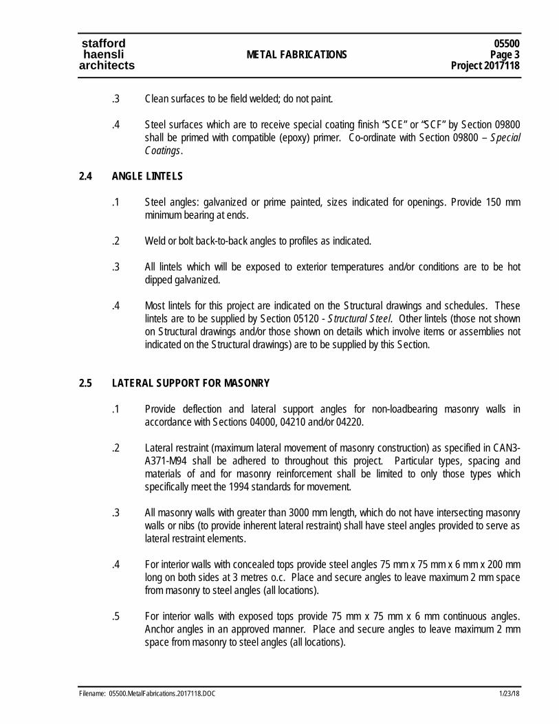
stafford 05500 haensli METAL FABRICATIONS Page 3 architects Project 2017118
Filename: 05500.MetalFabrications.2017118.DOC 1/23/18
.3 Clean surfaces to be field welded; do not paint. .4 Steel surfaces which are to receive special coating finish “SCE” or “SCF” by Section 09800
shall be primed with compatible (epoxy) primer. Co-ordinate with Section 09800 – Special Coatings.
2.4 ANGLE LINTELS .1 Steel angles: galvanized or prime painted, sizes indicated for openings. Provide 150 mm
minimum bearing at ends. .2 Weld or bolt back-to-back angles to profiles as indicated. .3 All lintels which will be exposed to exterior temperatures and/or conditions are to be hot
dipped galvanized. .4 Most lintels for this project are indicated on the Structural drawings and schedules. These
lintels are to be supplied by Section 05120 - Structural Steel. Other lintels (those not shown on Structural drawings and/or those shown on details which involve items or assemblies not indicated on the Structural drawings) are to be supplied by this Section.
2.5 LATERAL SUPPORT FOR MASONRY .1 Provide deflection and lateral support angles for non-loadbearing masonry walls in
accordance with Sections 04000, 04210 and/or 04220. .2 Lateral restraint (maximum lateral movement of masonry construction) as specified in CAN3-
A371-M94 shall be adhered to throughout this project. Particular types, spacing and materials of and for masonry reinforcement shall be limited to only those types which specifically meet the 1994 standards for movement.
.3 All masonry walls with greater than 3000 mm length, which do not have intersecting masonry
walls or nibs (to provide inherent lateral restraint) shall have steel angles provided to serve as lateral restraint elements.
.4 For interior walls with concealed tops provide steel angles 75 mm x 75 mm x 6 mm x 200 mm
long on both sides at 3 metres o.c. Place and secure angles to leave maximum 2 mm space from masonry to steel angles (all locations).
.5 For interior walls with exposed tops provide 75 mm x 75 mm x 6 mm continuous angles.
Anchor angles in an approved manner. Place and secure angles to leave maximum 2 mm space from masonry to steel angles (all locations).
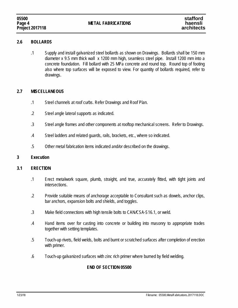
05500 stafford Page 4 METAL FABRICATIONS haensli Project 2017118 architects
1/23/18 Filename: 05500.MetalFabrications.2017118.DOC
2.6 BOLLARDS .1 Supply and install galvanized steel bollards as shown on Drawings. Bollards shall be 150 mm
diameter x 9.5 mm thick wall x 1200 mm high, seamless steel pipe. Install 1200 mm into a concrete foundation. Fill bollard with 25 MPa concrete and round top. Round top of footing also where top surfaces will be exposed to view. For quantity of bollards required, refer to drawings.
2.7 MISCELLANEOUS .1 Steel channels at roof curbs. Refer Drawings and Roof Plan. .2 Steel angle lateral supports as indicated. .3 Steel angle frames and other components at rooftop mechanical screens. Refer to Drawings. .4 Steel ladders and related guards, rails, brackets, etc., where so indicated. .5 Other metal fabrication items indicated and/or described on the drawings. 3 Execution 3.1 ERECTION .1 Erect metalwork square, plumb, straight, and true, accurately fitted, with tight joints and
intersections. .2 Provide suitable means of anchorage acceptable to Consultant such as dowels, anchor clips,
bar anchors, expansion bolts and shields, and toggles. .3 Make field connections with high tensile bolts to CAN/CSA-S16.1, or weld. .4 Hand items over for casting into concrete or building into masonry to appropriate trades
together with setting templates. .5 Touch-up rivets, field welds, bolts and burnt or scratched surfaces after completion of erection
with primer. .6 Touch-up galvanized surfaces with zinc rich primer where burned by field welding. END OF SECTION 05500
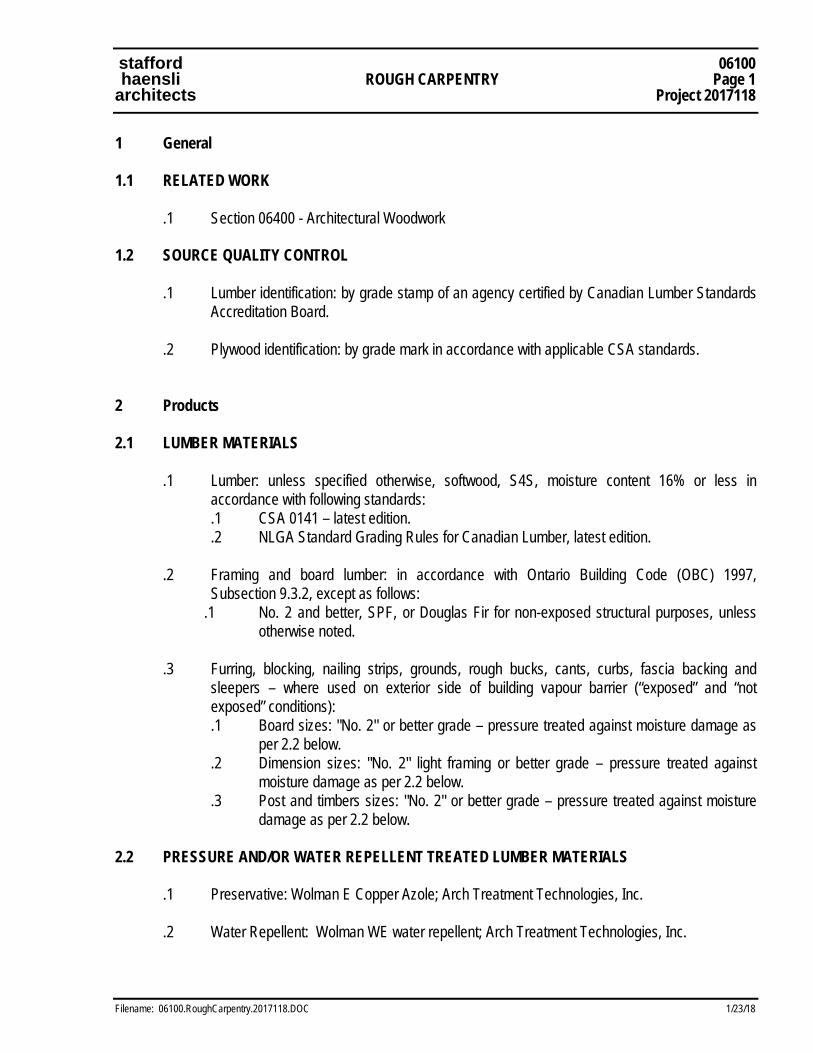
stafford 06100 haensli ROUGH CARPENTRY Page 1 architects Project 2017118
Filename: 06100.RoughCarpentry.2017118.DOC 1/23/18
1 General 1.1 RELATED WORK .1 Section 06400 - Architectural Woodwork 1.2 SOURCE QUALITY CONTROL .1 Lumber identification: by grade stamp of an agency certified by Canadian Lumber Standards
Accreditation Board. .2 Plywood identification: by grade mark in accordance with applicable CSA standards. 2 Products 2.1 LUMBER MATERIALS .1 Lumber: unless specified otherwise, softwood, S4S, moisture content 16% or less in
accordance with following standards: .1 CSA 0141 – latest edition. .2 NLGA Standard Grading Rules for Canadian Lumber, latest edition. .2 Framing and board lumber: in accordance with Ontario Building Code (OBC) 1997,
Subsection 9.3.2, except as follows: .1 No. 2 and better, SPF, or Douglas Fir for non-exposed structural purposes, unless
otherwise noted. .3 Furring, blocking, nailing strips, grounds, rough bucks, cants, curbs, fascia backing and
sleepers – where used on exterior side of building vapour barrier (“exposed” and “not exposed” conditions):
.1 Board sizes: "No. 2" or better grade – pressure treated against moisture damage as per 2.2 below.
.2 Dimension sizes: "No. 2" light framing or better grade – pressure treated against moisture damage as per 2.2 below.
.3 Post and timbers sizes: "No. 2" or better grade – pressure treated against moisture damage as per 2.2 below.
2.2 PRESSURE AND/OR WATER REPELLENT TREATED LUMBER MATERIALS
.1 Preservative: Wolman E Copper Azole; Arch Treatment Technologies, Inc. .2 Water Repellent: Wolman WE water repellent; Arch Treatment Technologies, Inc.

06100 stafford Page 2 ROUGH CARPENTRY haensli Project 2017118 architects
1/23/18 Filename: 06100.RoughCarpentry.2017118.DOC
.3 Pressure Treatment: In accordance with the requirements of AWPA Standard C1 and in accordance with the following standards for indicated end uses:
.1 Lumber: C2. .2 Plywood: C9.
.4 Minimum Preservative Retention: In accordance with the specified standard, determined in the specified zone, for the following applications: .1 Above Ground. .2 Ground or Fresh Water Contact. .3 Structural Posts and Poles (Sawn or Round).
.5 Water Repellent Treatment: Factory water repellent applied with preservative treatment.
.6 Pressure Treated Lumber for Roofing “Sleepers” and/or Landscape Work (exterior): Kiln
dried Pine, No. 1 grade, largely free of cracks, checks and other deformities. Lumber to be pressure preservative treated. Pressure treated lumber is to carry manufacturer's full warranty. All cut ends to be treated on site with compatible brush-on treatment. Submit Material Safety Data Sheet for brush-on end cut treatment.
2.3 PANEL STANDARDS .1 Panel standards: type, grade and thickness as specified indicated, in accordance with
following standards: .1 Douglas fir plywood (DFP): to CSA 0121, standard construction. .2 Canadian softwood plywood (CSP): to CSA 0151, standard construction. .3 Interior mat-formed wood particleboard: to CAN3-0188.1. .4 Hardboard: to CAN/CGSB-11.3.
.2 Please Note: ALL plywood panels used as part of roof, soffit, fascia, canopy, siding and/or
any other “exposed” or “semi-exposed” location shall be pressure treated against moisture damage as per 2.1 above.
2.4 FASTENERS .1 Nails, spikes and staples: to CSA B111. .2 Bolts: 10 mm diameter unless indicated otherwise, complete with nuts and washers. .3 Proprietary fasteners: toggle bolts, expansion shields and lag bolts, screws and lead or
inorganic fibre plugs, recommended for purpose by manufacturer. .4 Galvanizing: to CSA G164, use galvanized fasteners for exterior work and all pressure-
preservative treated lumber.
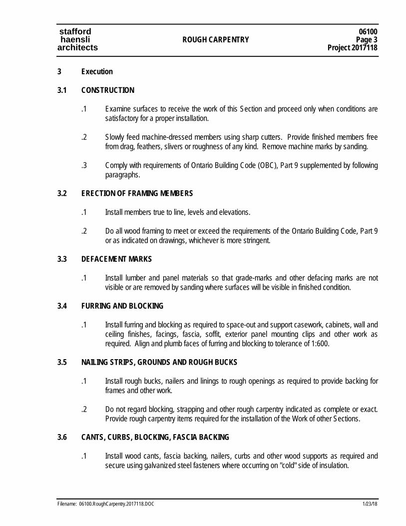
stafford 06100 haensli ROUGH CARPENTRY Page 3 architects Project 2017118
Filename: 06100.RoughCarpentry.2017118.DOC 1/23/18
3 Execution 3.1 CONSTRUCTION .1 Examine surfaces to receive the work of this Section and proceed only when conditions are
satisfactory for a proper installation. .2 Slowly feed machine-dressed members using sharp cutters. Provide finished members free
from drag, feathers, slivers or roughness of any kind. Remove machine marks by sanding. .3 Comply with requirements of Ontario Building Code (OBC), Part 9 supplemented by following
paragraphs. 3.2 ERECTION OF FRAMING MEMBERS .1 Install members true to line, levels and elevations. .2 Do all wood framing to meet or exceed the requirements of the Ontario Building Code, Part 9
or as indicated on drawings, whichever is more stringent. 3.3 DEFACEMENT MARKS .1 Install lumber and panel materials so that grade-marks and other defacing marks are not
visible or are removed by sanding where surfaces will be visible in finished condition. 3.4 FURRING AND BLOCKING .1 Install furring and blocking as required to space-out and support casework, cabinets, wall and
ceiling finishes, facings, fascia, soffit, exterior panel mounting clips and other work as required. Align and plumb faces of furring and blocking to tolerance of 1:600.
3.5 NAILING STRIPS, GROUNDS AND ROUGH BUCKS .1 Install rough bucks, nailers and linings to rough openings as required to provide backing for
frames and other work. .2 Do not regard blocking, strapping and other rough carpentry indicated as complete or exact.
Provide rough carpentry items required for the installation of the Work of other Sections. 3.6 CANTS, CURBS, BLOCKING, FASCIA BACKING .1 Install wood cants, fascia backing, nailers, curbs and other wood supports as required and
secure using galvanized steel fasteners where occurring on "cold" side of insulation.
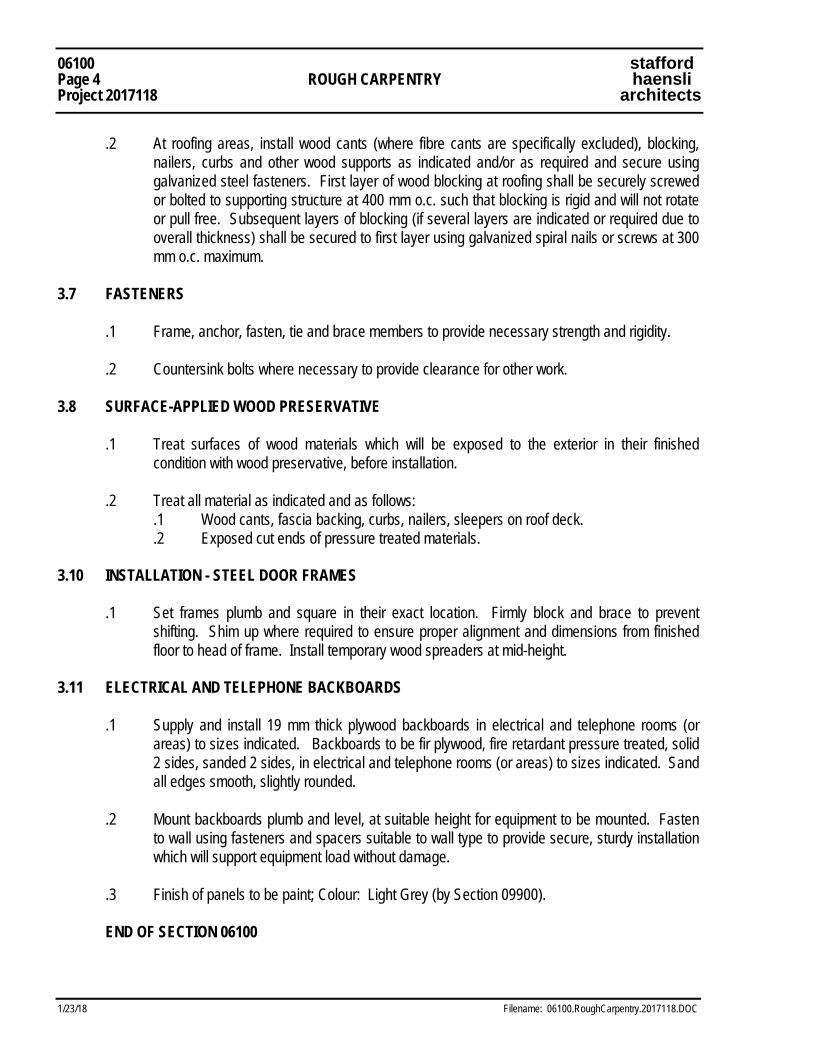
06100 stafford Page 4 ROUGH CARPENTRY haensli Project 2017118 architects
1/23/18 Filename: 06100.RoughCarpentry.2017118.DOC
.2 At roofing areas, install wood cants (where fibre cants are specifically excluded), blocking, nailers, curbs and other wood supports as indicated and/or as required and secure using galvanized steel fasteners. First layer of wood blocking at roofing shall be securely screwed or bolted to supporting structure at 400 mm o.c. such that blocking is rigid and will not rotate or pull free. Subsequent layers of blocking (if several layers are indicated or required due to overall thickness) shall be secured to first layer using galvanized spiral nails or screws at 300 mm o.c. maximum.
3.7 FASTENERS .1 Frame, anchor, fasten, tie and brace members to provide necessary strength and rigidity. .2 Countersink bolts where necessary to provide clearance for other work. 3.8 SURFACE-APPLIED WOOD PRESERVATIVE .1 Treat surfaces of wood materials which will be exposed to the exterior in their finished
condition with wood preservative, before installation. .2 Treat all material as indicated and as follows: .1 Wood cants, fascia backing, curbs, nailers, sleepers on roof deck. .2 Exposed cut ends of pressure treated materials. 3.10 INSTALLATION - STEEL DOOR FRAMES .1 Set frames plumb and square in their exact location. Firmly block and brace to prevent
shifting. Shim up where required to ensure proper alignment and dimensions from finished floor to head of frame. Install temporary wood spreaders at mid-height.
3.11 ELECTRICAL AND TELEPHONE BACKBOARDS .1 Supply and install 19 mm thick plywood backboards in electrical and telephone rooms (or
areas) to sizes indicated. Backboards to be fir plywood, fire retardant pressure treated, solid 2 sides, sanded 2 sides, in electrical and telephone rooms (or areas) to sizes indicated. Sand all edges smooth, slightly rounded.
.2 Mount backboards plumb and level, at suitable height for equipment to be mounted. Fasten
to wall using fasteners and spacers suitable to wall type to provide secure, sturdy installation which will support equipment load without damage.
.3 Finish of panels to be paint; Colour: Light Grey (by Section 09900).
END OF SECTION 06100
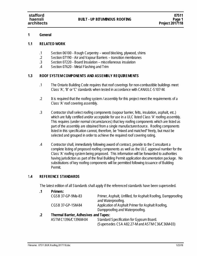
stafford 07511 haensli BUILT - UP BITUMINOUS ROOFING Page 1 architects Project 2017118
Filename: 07511.BUR.Roofing.2017118.doc 1/23/18
1 General 1.1 RELATED WORK
.1 Section 06100 - Rough Carpentry – wood blocking, plywood, shims
.2 Section 07190 - Air and Vapour Barriers – transition membranes
.3 Section 07220 - Board Insulation – miscellaneous insulation
.4 Section 07620 - Metal Flashing and Trim 1.3 ROOF SYSTEM COMPONENTS AND ASSEMBLY REQUIREMENTS
.1 The Ontario Building Code requires that roof coverings for non-combustible buildings meet Class ‘A’, ‘B’ or ‘C’ standards when tested in accordance with CAN/ULC-S107-M.
.2 It is required that the roofing system / assembly for this project meet the requirements of a
Class ‘A’ roof covering assembly. .3 Contractor shall select roofing components (vapour barrier, felts, insulation, asphalt, etc.)
which are fully certified and/or acceptable for use in a ULC listed Class ‘A’ roofing assembly. This requires (under normal circumstances) that key roofing components which are listed as part of the assembly are obtained from a single manufacturer/source. Roofing components listed in this specification cannot, therefore, be “mixed and matched” freely, but must be selected and grouped in order to achieve the required roof covering rating.
.4 Contractor shall, immediately following award of contract, provide to the Consultant a
complete listing of proposed roofing components as well as the ULC approval number for the Class ‘A’ roofing system being proposed. This information will be forwarded to authorities having jurisdiction as part of the final Building Permit application documentation package. No substitutions of key roofing components will be permitted following issuance of Building Permit.
1.4 REFERENCE STANDARDS
The latest edition of all Standards shall apply if the referenced standards have been superseded. .1 Primers:
CGSB 37-GP-9Ma-83 Primer, Asphalt, Unfilled, for Asphalt Roofing, Dampproofing and Waterproofing.
CGSB 37-GP-15M-84 Application of Asphalt Primer for Asphalt Roofing, Dampproofing and Waterproofing.
.2 Thermal Barrier, Adhesives and Tapes: ASTM C1396/C1396M-04 Standard Specification for Gypsum Board.
(Supersedes CSA A82.27-M and ASTM C36/C36M-03)
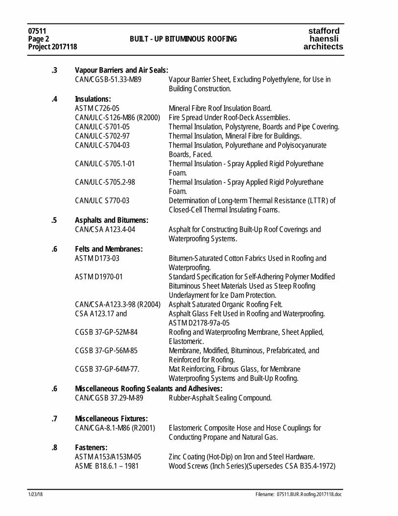
07511 stafford Page 2 BUILT - UP BITUMINOUS ROOFING haensli Project 2017118 architects
1/23/18 Filename: 07511.BUR.Roofing.2017118.doc
.3 Vapour Barriers and Air Seals: CAN/CGSB-51.33-M89 Vapour Barrier Sheet, Excluding Polyethylene, for Use in
Building Construction. .4 Insulations:
ASTM C726-05 Mineral Fibre Roof Insulation Board. CAN/ULC-S126-M86 (R2000) Fire Spread Under Roof-Deck Assemblies. CAN/ULC-S701-05 Thermal Insulation, Polystyrene, Boards and Pipe Covering. CAN/ULC-S702-97 Thermal Insulation, Mineral Fibre for Buildings. CAN/ULC-S704-03 Thermal Insulation, Polyurethane and Polyisocyanurate
Boards, Faced. CAN/ULC-S705.1-01 Thermal Insulation - Spray Applied Rigid Polyurethane
Foam. CAN/ULC-S705.2-98 Thermal Insulation - Spray Applied Rigid Polyurethane
Foam. CAN/ULC S770-03 Determination of Long-term Thermal Resistance (LTTR) of
Closed-Cell Thermal Insulating Foams. .5 Asphalts and Bitumens:
CAN/CSA A123.4-04 Asphalt for Constructing Built-Up Roof Coverings and Waterproofing Systems.
.6 Felts and Membranes: ASTM D173-03 Bitumen-Saturated Cotton Fabrics Used in Roofing and
Waterproofing. ASTM D1970-01 Standard Specification for Self-Adhering Polymer Modified
Bituminous Sheet Materials Used as Steep Roofing Underlayment for Ice Dam Protection.
CAN/CSA-A123.3-98 (R2004) Asphalt Saturated Organic Roofing Felt. CSA A123.17 and Asphalt Glass Felt Used in Roofing and Waterproofing.
ASTM D2178-97a-05 CGSB 37-GP-52M-84 Roofing and Waterproofing Membrane, Sheet Applied,
Elastomeric. CGSB 37-GP-56M-85 Membrane, Modified, Bituminous, Prefabricated, and
Reinforced for Roofing. CGSB 37-GP-64M-77. Mat Reinforcing, Fibrous Glass, for Membrane
Waterproofing Systems and Built-Up Roofing. .6 Miscellaneous Roofing Sealants and Adhesives:
CAN/CGSB 37.29-M-89 Rubber-Asphalt Sealing Compound. .7 Miscellaneous Fixtures:
CAN/CGA-8.1-M86 (R2001) Elastomeric Composite Hose and Hose Couplings for Conducting Propane and Natural Gas.
.8 Fasteners: ASTM A153/A153M-05 Zinc Coating (Hot-Dip) on Iron and Steel Hardware. ASME B18.6.1 – 1981 Wood Screws (Inch Series)(Supersedes CSA B35.4-1972)
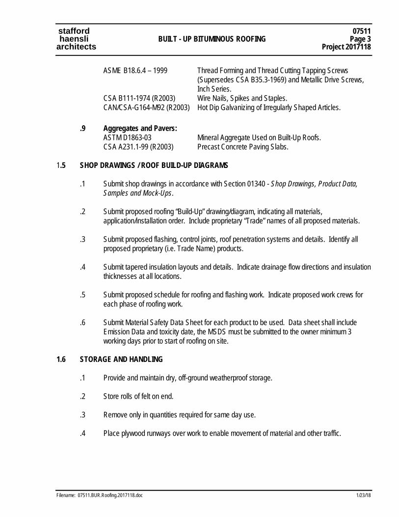
stafford 07511 haensli BUILT - UP BITUMINOUS ROOFING Page 3 architects Project 2017118
Filename: 07511.BUR.Roofing.2017118.doc 1/23/18
ASME B18.6.4 – 1999 Thread Forming and Thread Cutting Tapping Screws (Supersedes CSA B35.3-1969) and Metallic Drive Screws, Inch Series.
CSA B111-1974 (R2003) Wire Nails, Spikes and Staples. CAN/CSA-G164-M92 (R2003) Hot Dip Galvanizing of Irregularly Shaped Articles.
.9 Aggregates and Pavers:
ASTM D1863-03 Mineral Aggregate Used on Built-Up Roofs. CSA A231.1-99 (R2003) Precast Concrete Paving Slabs.
1.5 SHOP DRAWINGS / ROOF BUILD-UP DIAGRAMS
.1 Submit shop drawings in accordance with Section 01340 - Shop Drawings, Product Data, Samples and Mock-Ups.
.2 Submit proposed roofing “Build-Up” drawing/diagram, indicating all materials,
application/installation order. Include proprietary “Trade” names of all proposed materials. .3 Submit proposed flashing, control joints, roof penetration systems and details. Identify all
proposed proprietary (i.e. Trade Name) products. .4 Submit tapered insulation layouts and details. Indicate drainage flow directions and insulation
thicknesses at all locations. .5 Submit proposed schedule for roofing and flashing work. Indicate proposed work crews for
each phase of roofing work. .6 Submit Material Safety Data Sheet for each product to be used. Data sheet shall include
Emission Data and toxicity date, the MSDS must be submitted to the owner minimum 3 working days prior to start of roofing on site.
1.6 STORAGE AND HANDLING
.1 Provide and maintain dry, off-ground weatherproof storage. .2 Store rolls of felt on end. .3 Remove only in quantities required for same day use. .4 Place plywood runways over work to enable movement of material and other traffic.
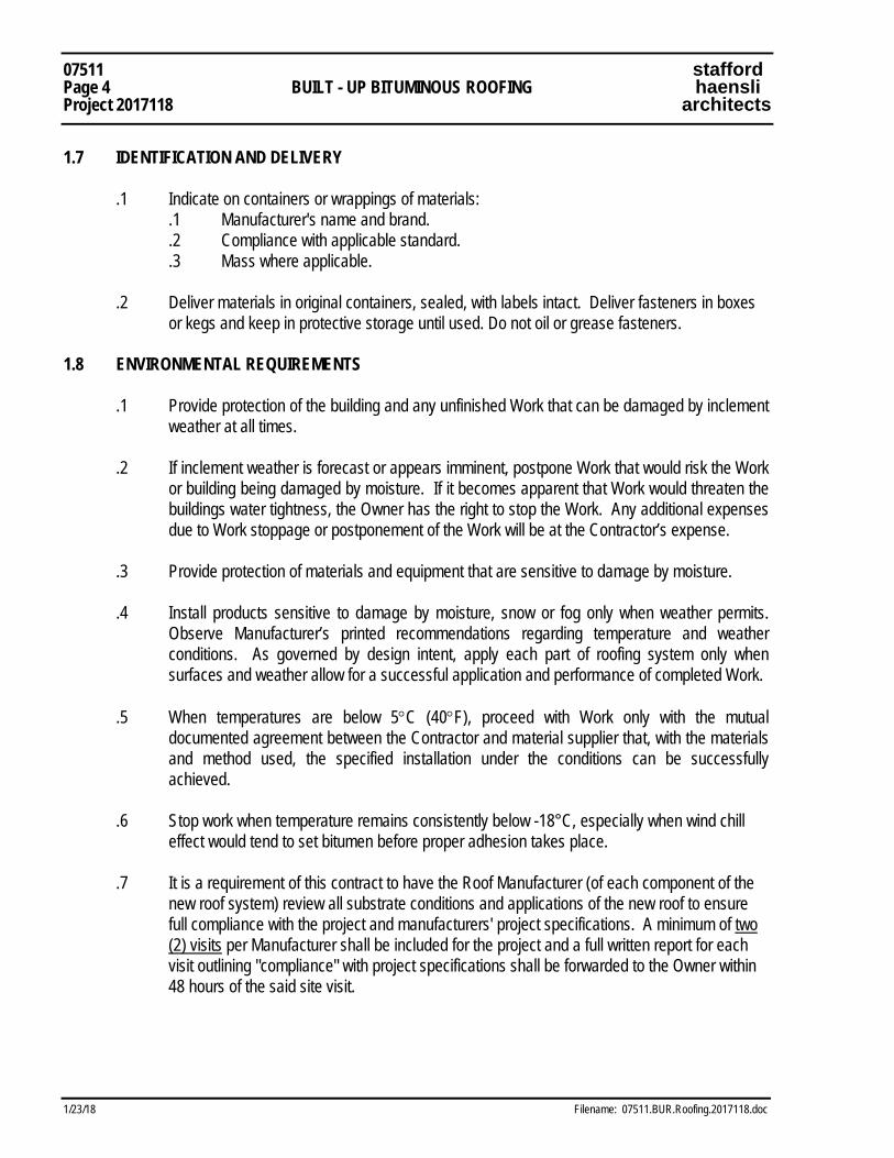
07511 stafford Page 4 BUILT - UP BITUMINOUS ROOFING haensli Project 2017118 architects
1/23/18 Filename: 07511.BUR.Roofing.2017118.doc
1.7 IDENTIFICATION AND DELIVERY .1 Indicate on containers or wrappings of materials: .1 Manufacturer's name and brand. .2 Compliance with applicable standard. .3 Mass where applicable.
.2 Deliver materials in original containers, sealed, with labels intact. Deliver fasteners in boxes or kegs and keep in protective storage until used. Do not oil or grease fasteners.
1.8 ENVIRONMENTAL REQUIREMENTS
.1 Provide protection of the building and any unfinished Work that can be damaged by inclement weather at all times.
.2 If inclement weather is forecast or appears imminent, postpone Work that would risk the Work
or building being damaged by moisture. If it becomes apparent that Work would threaten the buildings water tightness, the Owner has the right to stop the Work. Any additional expenses due to Work stoppage or postponement of the Work will be at the Contractor’s expense.
.3 Provide protection of materials and equipment that are sensitive to damage by moisture. .4 Install products sensitive to damage by moisture, snow or fog only when weather permits.
Observe Manufacturer’s printed recommendations regarding temperature and weather conditions. As governed by design intent, apply each part of roofing system only when surfaces and weather allow for a successful application and performance of completed Work.
.5 When temperatures are below 5°C (40°F), proceed with Work only with the mutual
documented agreement between the Contractor and material supplier that, with the materials and method used, the specified installation under the conditions can be successfully achieved.
.6 Stop work when temperature remains consistently below -18°C, especially when wind chill
effect would tend to set bitumen before proper adhesion takes place. .7 It is a requirement of this contract to have the Roof Manufacturer (of each component of the
new roof system) review all substrate conditions and applications of the new roof to ensure full compliance with the project and manufacturers' project specifications. A minimum of two (2) visits per Manufacturer shall be included for the project and a full written report for each visit outlining "compliance" with project specifications shall be forwarded to the Owner within 48 hours of the said site visit.

stafford 07511 haensli BUILT - UP BITUMINOUS ROOFING Page 5 architects Project 2017118
Filename: 07511.BUR.Roofing.2017118.doc 1/23/18
1.9 WARRANTY
.1 Manufacturer of roofing system materials and Roofing Sub-Contractor hereby warrants that complete built-up roofing system and membrane flashings will stay in place and remain leakproof in accordance with the contract documents, but for Ten (10) years. It is understood that the specified warranty may include two (2) year “Roofer’s Warranty” and additional eight (8) year “Manufacturer’s Warranty”. Submit proposed warranty documents for review and approval prior to completion of roofing operations.
.2 All warranties/guarantees for the project shall include materials and labour.
.3 Manufacturer’s Warranty Requirements: The Contractor shall provide a single source
manufacturer's system warranty (No Dollar Limit) for all work of this section against defects in materials and workmanship for a period of ten (10) years. The written warranty shall be in a form approved by the owner. The warranty shall cover all components of the roof system; including, but not limited to, the vapour retarder, roof insulation, roof membrane, flood coat/gravel and base flashings. The manufacturer supply all labour, materials, tools and equipment to repair and/or replace any material defects, at no additional cost, for a period of ten (10) years. The warranty shall not be pro-rated over the ten (10) year period. The warranty shall be issued to the Owner within two (2) working days following the date of substantial completion.
1.10 INSPECTION AND TESTING
.1 Roof Inspection and Testing will be carried out by an Inspection and Testing Agency as designated by the Consultant.
.2 Inspection and Testing will be in accordance with Section 01410 - Testing Laboratory
Services and will be paid for by Cash Allowance specified in Section 01010 - Allowances.
1.11 COMPATIBILITY
.1 Compatibility between components of roofing system is essential. Bituminous adhesives, insulation, felts, and surface coatings which are to be incorporated into system must be compatible with each other.
.2 Provide written declaration that components of roofing system are compatible.
1.12 HEALTH AND SAFETY REQUIREMENTS
.1 The Contractor shall comply with the requirements as provided in the Hot Work and Safety Checklist where welding, soldering or torching on the roof is to take place.
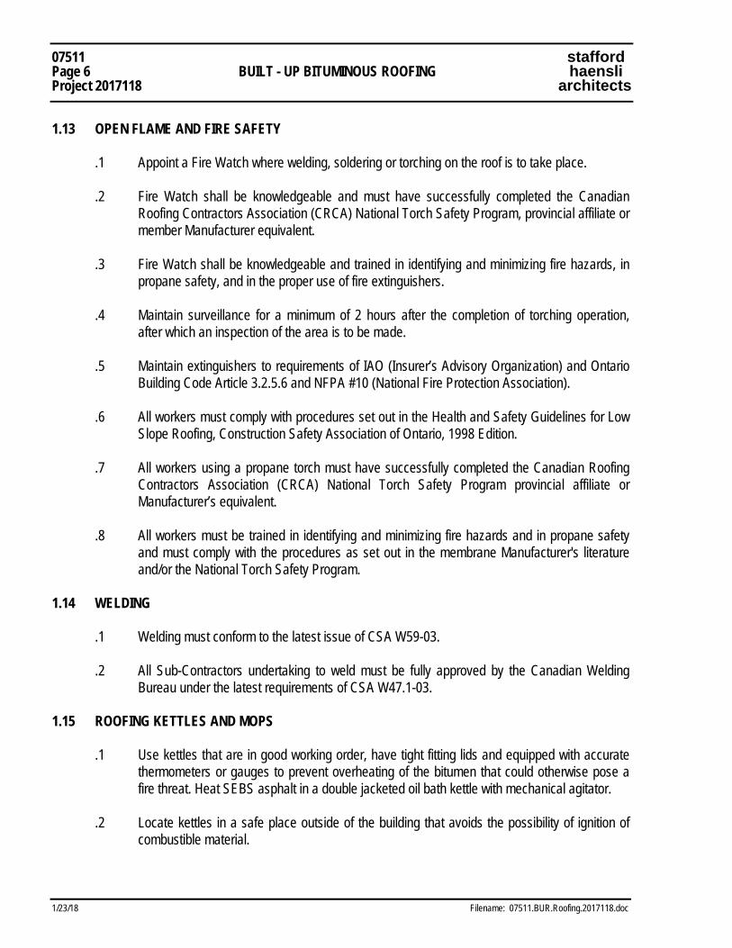
07511 stafford Page 6 BUILT - UP BITUMINOUS ROOFING haensli Project 2017118 architects
1/23/18 Filename: 07511.BUR.Roofing.2017118.doc
1.13 OPEN FLAME AND FIRE SAFETY
.1 Appoint a Fire Watch where welding, soldering or torching on the roof is to take place. .2 Fire Watch shall be knowledgeable and must have successfully completed the Canadian
Roofing Contractors Association (CRCA) National Torch Safety Program, provincial affiliate or member Manufacturer equivalent.
.3 Fire Watch shall be knowledgeable and trained in identifying and minimizing fire hazards, in
propane safety, and in the proper use of fire extinguishers. .4 Maintain surveillance for a minimum of 2 hours after the completion of torching operation,
after which an inspection of the area is to be made. .5 Maintain extinguishers to requirements of IAO (Insurer’s Advisory Organization) and Ontario
Building Code Article 3.2.5.6 and NFPA #10 (National Fire Protection Association). .6 All workers must comply with procedures set out in the Health and Safety Guidelines for Low
Slope Roofing, Construction Safety Association of Ontario, 1998 Edition. .7 All workers using a propane torch must have successfully completed the Canadian Roofing
Contractors Association (CRCA) National Torch Safety Program provincial affiliate or Manufacturer’s equivalent.
.8 All workers must be trained in identifying and minimizing fire hazards and in propane safety
and must comply with the procedures as set out in the membrane Manufacturer's literature and/or the National Torch Safety Program.
1.14 WELDING
.1 Welding must conform to the latest issue of CSA W59-03. .2 All Sub-Contractors undertaking to weld must be fully approved by the Canadian Welding
Bureau under the latest requirements of CSA W47.1-03.
1.15 ROOFING KETTLES AND MOPS
.1 Use kettles that are in good working order, have tight fitting lids and equipped with accurate thermometers or gauges to prevent overheating of the bitumen that could otherwise pose a fire threat. Heat SEBS asphalt in a double jacketed oil bath kettle with mechanical agitator.
.2 Locate kettles in a safe place outside of the building that avoids the possibility of ignition of
combustible material.
stafford 07511 haensli BUILT - UP BITUMINOUS ROOFING Page 7 architects Project 2017118
Filename: 07511.BUR.Roofing.2017118.doc 1/23/18
.3 Maintain continuous supervision while kettles are in operation and provide metal covers for the kettles to smother any flames in case of fire.
.4 Disconnect propane burners from heating containers when not in use. Store propane in
protected area away from ignition sources and buildings. Contact local Fire Chief and advise of Work in progress. Act on instructions given to render the site free of fire hazards.
.5 Use only glass fibre roofing mops. Do not leave used roofing mops on the roof unattended.
Store mops away from the building and combustible materials. Remove from site daily. .6 Supply and maintain in good working order, ABC fire extinguishers with a minimum of 4.5 kg
(10 lbs) capacity at the kettle and at each location where Work is in progress including at ground level, kettles and tankers. Keep extinguishers in locations away from propane tanks. A separate fire extinguisher must be provided to the Fire Watch.
1.16 PRE-CONSTRUCTION ROOFING SITE MEETING
.1 Approximately four (4) weeks prior to scheduled commencement of BUR installation and associated work, meet at project site with roofing subcontractor, installers of each component of associated work, installers of deck or substrate construction to receive roofing work, installers of roof top units and other work in and around roofing which must precede or follow roofing work (including electrical and mechanical work), Architect, Mechanical and Electrical Consultants, Owner, Roofing Inspection, and Testing Company.
.2 Review requirements (contract documents), submittals, status of co-ordinating work,
availability of materials and installation facilities and establish preliminary installation schedule. Review requirements for inspection and testing and proposed installation procedures.
.3 Discuss roof protection requirements for construction period extending beyond roofing
installation.

07511 stafford Page 8 BUILT - UP BITUMINOUS ROOFING haensli Project 2017118 architects
1/23/18 Filename: 07511.BUR.Roofing.2017118.doc
2 Products 2.1 MATERIALS
.1 Roofing Materials (General): Acceptable Manufacturers of the built-up roof components include the following: Atlas, GAF, Henry (Monsey-Bakor), IKO, Johns Manville, Soprema, Tremco, Accu-Plane, Posi-Slope, Thaler. The latest (i.e. the most recent and most updated information) Manufacturers' technical data shall apply on this project. Any materials by manufacturers other than those listed above are to be submitted for approval prior to inclusion on this project. Unapproved products shall be changed for approved products at request of Consultant, at no additional cost to the project.
.2 Wood Blocking: solid wood, plywood and/or wood shims, pressure treated against moisture
damage, spruce/pine/fir (in case of solid wood members), spruce or fir (in case of plywood). .3 Vapour Barriers (Concrete Substrates):
.1 Two (2) plys of No. 15 felt each installed in a continuous layer of Type III asphalt.
.4 Insulation at Flat Roofs and at Prefinished Metal Roofing: Alternatives listed below indicate acceptable materials which may be selected/finalized by Contractor. Please note that the selected product may only be used in full accordance with the specific companion roofing products and systems described in this and other specifications sections. Overall insulation/roofing systems must carry the specified Warranties and roof coverings at flat roofs shall be ULC certified as Class A type.
.1 Roof Insulation: Polyisocyanurate closed cell foam insulation with inorganic or
fiberglass permeable facings. Rigid foam board, minimum compressive strength 138 kPa (20 psi), Type III, Class 2, manufactured with HC blowing agent, meeting requirements of CAN/ULC S126 and S107 and CAN/ULC-S704-03 and S770-03 for LTTR values. Approved and listed for Factory Mutual 1 - 75 wind classification and Factory Mutual 4470 requirements for Class 1 fire. Facings to be suitable for built-up bituminous or single ply membrane roofing installations. Facings to be dimensionally stable so as to not add bending stresses to insulation boards. Insulation is to be certified as meeting the requirements for use as part of a roof assembly in a non-combustible building without gypsum board underlayment.
.1 Thickness: 125 mm (5.0 in.). .2 Board Size: 1220 mm x 1220 mm (4 ft. x 4 ft.) or 1220 mm x 2440 mm (4 ft.
x 8 ft.), as standard by manufacturer for roofing applications of this kind. .3 Acceptable Material: “AC-FOAM-III” roof insulation as manufactured by Atlas
Roofing Corporation. .4 Acceptable Material: “ISO 300” roof insulation as manufactured by Firestone. .5 Acceptable Material: “IKOTHERM III” roof insulation as manufactured by IKO
Industries.
stafford 07511 haensli BUILT - UP BITUMINOUS ROOFING Page 9 architects Project 2017118
Filename: 07511.BUR.Roofing.2017118.doc 1/23/18
.6 Acceptable Material: “EL3000” roof insulation as manufactured by Celotex Corporation.
.5 Tapered Roof Insulation: Fiberboard, to CSA A247-M86 and ASTM C165, by Accu-Plane
Systems Inc., Posi-slope Enterprises Inc., or an approved alternate. Material to be fully compatible with roof insulation selected. Nominal board width to be 1200 mm. Installed in single or multiple layers to achieve indicated slope and coverage. For use on top of rigid roof insulation to provide roof slope and/or back-sloping for drainage. Refer to roof plan for extent. Note that fibreboard protection overlay shall be installed on top of tapered roof insulation (as well as main rigid roof insulation). If fibreboard is used for tapered roof insulation then no additional fibreboard overlay is required at tapered areas. Tapered insulation is noted as "SI" (sloped insulation) on roof plan.
.1 Nominal Slope: 2.0% nominal slope minimum; slope for 1200 or 2400 mm wide strips to be 50 mm in 1200 mm. Tapered insulation (each layer) to have minimum thickness of 0 mm, maximum thickness of 100 mm.
.2 Acceptable material: tapered insulation products by Posi-Slope Enterprises Inc., Accu-Plane or other manufacturer will be considered. Final approval will be based upon selected main roof insulation.
.6 Roof Protection Overlay: Protective overlay panels to be layered over roofing insulation,
specifically manufactured for this purpose. .1 Acceptable Material: “Securock” as manufactured by CGC / USG; impact resistant
fiber-reinforced gypsum panels; moisture and mould resistant through full thickness. Thickness: 10 mm (3/8 in.) or 13 mm (1/2 in.). Board size to be 1220 mm x 1220 mm or 1220 mm x 2440 mm (4 ft. x 4 ft. or 4 ft. x 8 ft.), as applicable to this roofing installation (protection boards should be same dimensions as rigid insulation).
.2 Acceptable Material: Fibreboard Overlay: 13 mm (1/2 inch) asphalt impregnated high density fibreboard overlay for rigid roof insulation, exterior grade, to be installed under built-up roofing. Board size to be 1220 mm x 1220 mm (4 ft. x 4 ft.).
.3 Acceptable Material: “Dens Deck” as manufactured by Georgia Pacific: 6 mm (1/4 inch) high density siliconized gypsum-based overlay for rigid roof insulation, exterior grade, to be installed under built-up roofing. Board size to be 1220 mm x 1220 mm (4 ft. x 4 ft.).
.7 Saturated Roofing Felts (Vapour Barrier): No. 15 asphalt saturated perforated roofing felt
(organic felt).
.8 Saturated Roofing Felts (Plys #1- #4): Type IV; asphalt coated, resin bonded glass fibre mat (glass felt).
.1 Acceptable Material: “Glass Ply Type IV” by Johns Manville. .2 Acceptable Material: “IKO Type IV Glass Ply Sheet” by IKO Industries. .3 Acceptable Material: “Superply Type IV Ply Sheet " by Monsey Bakor. .4 Acceptable Material: “Ply IV” by Firestone / BPCO.
.5 Acceptable Material: “THERMglass Plus” Type IV by Tremco.
07511 stafford Page 10 BUILT - UP BITUMINOUS ROOFING haensli Project 2017118 architects
1/23/18 Filename: 07511.BUR.Roofing.2017118.doc
.9 Asphalt Primer: as required for specific application locatons. .10 Roofing Asphalt (different types required for different applications):
.1 Roofing Asphalt (for Roofing Plys): to CSA A123.4 and ASTM D312, Type 2.
.2 Roofing/Flashing Asphalt (for Mod-Bit Flashings): same product as specified for roofing (Type 2 where possible, Type 3 as required for vertical surfaces).
.11 Plastic Cement: asphalt, to CGSB 37-GP-5. .12 Sealing Compound: to CGSB 37-GP-29, rubber asphalt type. .13 Modified Bituminous (Mod-Bit) Flashing: .1 Perimeter Roofing and Modified Bitumen Flashing Membranes - Base Sheet:
SBS modified bitumen sheet, non-woven polyester fibre reinforced, flexible for application with or without cant strips, suitable for mop-down application. Both base sheet and cap sheet are required at membrane flashings.
.1 Thickness: 3.0 mm .2 Weight of Reinforcing: 180 grams per square metre. .3 Acceptable Material - Base Sheet: “Sopralene 180” by Soprema Inc. (for
mop-down application and suitable for torch-down cap sheet), or approved equal by Henry (Monsey-Bakor), Siplast or Johns Manville.
.2 Modified Bitumen Flashing Membranes - Cap Sheet: SBS modified bitumen
sheet, non-woven polyester fibre reinforced, flexible for application with or without cant strips, suitable for mop-down or torch-down application as applicable per layer. Both base sheet and cap sheet are required at membrane flashings.
.1 Thickness: 4.5 mm on granules; 3.8 mm minimum. .2 Weight of Reinforcing: 250 grams per square metre. .3 Colour: Grey .4 Acceptable Material - Cap Sheet: “Sopralene Flam 250” by Soprema Inc. (for
torch-down application over base sheet), or approved equal by Henry (Monsey-Bakor), Siplast or Johns Manville.
.14 Gravel: to ASTM D1863-86, 5 mm to 12 mm maximum size, washed, free from dirt and other
contaminants. .15 Cant Strips: fibre composite type or solid wood type as recommended by membrane roofing
manufacturer. Nominal dimensions to be 100 mm x 100 mm (4 in. x 4 in.). .16 Accessories:
.1 Adhesive: listed by ULC under Roof Deck Construction Materials, Guide No. 360 R13 and as recommended by manufacturer of material being adhered and for use under climatic conditions to be encountered.
stafford 07511 haensli BUILT - UP BITUMINOUS ROOFING Page 11 architects Project 2017118
Filename: 07511.BUR.Roofing.2017118.doc 1/23/18
.2 Screws for Fastening Insulation to Steel Decks: to CSA B35.3, No. 10 flat head
self-tapping screws, Type A, Phillips, cadmium plated steel, complete with plastic load-spreading washers made specifically for this purpose. Fasteners to be approved by ULC or Factory Mutual, length to suit application.
.3 Sealing Compound: to CAN/CGSB-19.24 or CAN/CGSB-19.13. .4 Termination Bars/Batten Bars: Rigid galvanized steel or aluminum material, 3
metre lengths, for effective seal for terminating modified flashing on vertical surfaces. Stips to be pre-drilled for screw fastening.
.5 Pre-Insulated Vent Stack Jack Flashings with Vandal Proof Caps: Type SJ-31
aluminum pre-insulated stack jacks with SJ-33 stainless steel vandal proof vent stack caps as manufactured by Thaler Roofing Specialties. All stack jacks to be 330 mm (13”) high. For diameter size and quantities, refer to Mechanical drawings.
.6 Exhaust Vent Flashings: Type EVF-1 or E VF-2 aluminum pre-insulated, pre-
manufactured dryer and exhaust vents as manufactured by Thaler Roofing Specialties. All vents to be 330 mm (13”) high. For size and quantities, refer to Mechanical drawings.
.7 Flexible Conduit Flashings: Type MEF-2C copper pre-insulated flexible conduit
flashings as manufactured by Thaler Roofing Specialties. All flashings to be 330 mm (13”) high. For size and quantities, refer to Electrical and Mechanical drawings.
.8 Rigid Conduit Flashings (50 to 200 mm diameter): Type MEF-1A aluminum pre-
insulated rigid conduit flashings as manufactured by Thaler Roofing Specialties. All flashings to be 330 mm (13”) high. For size and quantities, refer to Electrical and Mechanical drawings.
.9 Rigid Conduit Flashings (200 to 1000 mm diameter): Type MEF-3A aluminum
pre-insulated rigid conduit flashings as manufactured by Thaler Roofing Specialties. All flashings to be 330 mm (13”) high. For size and quantities, refer to Electrical and Mechanical drawings.
.10 Pipe Penetration Flashings (50 to 200 mm diameter): Same as for Item .8 above.
.17 Sheet Metal Closure Strips: 0.457 mm (26 ga) sheet steel, prefinished with baked enamel or galvanized finish, 'L' shaped profile, legs of applicable length to suit location x longest practical lengths. For use behind wood blocking, at wall/deck faces, etc. to provide continuation of air barrier from wall to roof."
07511 stafford Page 12 BUILT - UP BITUMINOUS ROOFING haensli Project 2017118 architects
1/23/18 Filename: 07511.BUR.Roofing.2017118.doc
.18 Roof Supports and Anchors: products as manufactured by Thaler Roofing Specialties Products Inc. Products by other manufacturers may be considered upon submission of full product data including load capacities, details, sizes, etc. Refer to Roof Plan and details for locations, layout and mounting interfaces.
.1 Acceptable Material: Model “ARS-530” by Thaler, complete with 152 mm x 152 mm x 6 mm thick steel top plate/cap, aluminum outer sleeve, premoulded urethane insulation, steel support pipe and base plate. Top plate/cap is to be adjustable for height via a 25 mm diameter threaded rod support. Unit to be suitable for installation at PVC single ply membrane roofs.
.2 Quantity: Number and location as indicated or as required for re-installation of existing screening when re-roofing work is undertaken.
.19 Penetration Seals (Miscellaneous): ChemCurb System as supplied by ChemLink or an
approved equal. Contact Building Resource: Mr. Michael Pace 416-410-4055 for additional information. All installations shall be verified on site by Manufacturer/Supplier.
3 Execution 3.1 PLANT AND EQUIPMENT
.1 Use only kettles equipped with thermometers or gauges in good working order. .2 Locate kettles in safe place outside of building or, if approved by Consultant, on non-
combustible roof at location to avoid danger of igniting combustible material below. When locating kettles, give consideration to direction of prevailing winds, building fans and air handling units to minimize possibility of smoke and fumes entering surrounding occupied buildings. If wind direction causes smoke and fume problems, relocate kettles on daily basis when directed by Consultant.
.3 Maintain continuous supervision while kettles are in operation and provide metal covers for
kettles to smother flames in case of fire. Provide suitable fire extinguishers. .4 Maintain efficiency of kettles and equipment by frequent cleaning. Remove all carbonized
bitumen. .5 Prior to start of work, demonstrate container capacities and spread rate of machines to
Consultant. .6 Use only fibreglass roofing mops. .7 Do not leave used roofing mops unattended on roof; store away from building and
combustible materials.

stafford 07511 haensli BUILT - UP BITUMINOUS ROOFING Page 13 architects Project 2017118
Filename: 07511.BUR.Roofing.2017118.doc 1/23/18
.8 General Open Flame Precautions / Requirements: .1 Training:
.1 The Roofing Contractor shall thoroughly train all personnel in the recommended safety procedures for the use of kettles asphalt moppings, propane torching and the application of roofing products.
.2 Roofing industry associations have developed training programs for the safe use of kettles and torches. All applicators of modified bituminous roof membranes shall have attended appropriate training for the safe installation of the materials.
.3 The contractor shall train all personnel in the proper use of fire extinguishers as well as fire prevention and related fire fighting procedures.
.4 The Contractor shall train all personnel on first aid
.2 Propane Torch Precautions .1 The Contractor shall train all personnel in the proper set up and use of
propane and torch equipment. All Contractors shall follow all HOT WORK procedures as outlined by the PDSB and Factory Mutual.
.2 The torch operator shall maintain control over the torch flame at all times.
.3 Provide at least one fully charged twenty (20) pound (9 kg.) type ABC rated fire extinguisher for each torching device on the roof. The fire extinguishers should be stored in the immediate work area away from where the propane is being stored.
.4 Never torch directly to combustible materials. Personnel shall exercise extreme caution around the exposed edges of insulation to prevent flames from coming in contact with combustible materials.
.5 Do not use torching equipment in confined spaces or areas without sufficient ventilation.
.6 Conduct fire prevention inspections periodically during installation. A minimum one (1) hour fire watch should be conducted after the last torch has been extinguished for the day. The length of the fire watch may vary depending on the specifics of the project and the work completed each day.
3.2 PROTECTION
.1 Cover walls and adjacent work where materials hoisted or used. .2 Cover walls and adjacent work when roof operations are taking place near edge of roof. .3 Use warning signs and barriers. Maintain in good order until completion of work. .4 Clean off drips and smears of bituminous material. .5 Dispose of rain water off roof and away from face of building until roof drains or hoppers
installed and connected.
07511 stafford Page 14 BUILT - UP BITUMINOUS ROOFING haensli Project 2017118 architects
1/23/18 Filename: 07511.BUR.Roofing.2017118.doc
.6 Prevent traffic over completed roofing except where required by work above roof level. Comply with precautions deemed necessary by Consultant. Repair damage caused by non-compliance with Consultant's requirements.
.7 At end of each day's work or when stoppage occurs due to inclement weather, provide
protection for completed work and materials out of storage. .8 Cover air vents/openings to the existing school.
3.3 EXAMINATION OF ROOF DECKS
.1 Examine roof decks and immediately inform Consultant in writing of defects. .2 Prior to commencement of work ensure:
.1 Decks are firm, straight, smooth, dry, free of snow, ice or frost, and swept clean of dust and debris.
.2 Curbs have been built.
.3 Roof drains have been installed at proper elevations relative to finished roof surface, and have been installed level and secure Take spot levels to verify that pools of water will not form on applied roofing. Tabulate levels and submit to Consultant when so requested in writing (to be done prior to the application of insulation).
..4 Plywood and lumber nailer plates have been installed to walls and parapets as indicated.
3.4 PREPARATION OF STEEL DECK (CHANNEL TYPE)
.1 Not applicable for the work described in this Section 07511. 3.5 PRIMING CONCRETE DECK
.1 Brush or spray asphalt primer on concrete deck areas which will be in contact with bitumens in accordance with CGSB 37-GP-15M at minimum rate of 0.37 L/m2.
.2 Prevent pooling and seepage through joints. Allow to cure.
3.6 ROOFING ASPHALT
.1 Apply roofing asphalt at plus or minus 15°C of EVT indicated on Bill of Lading. .2 Maintain asphalt in tanker at or below its FBT indicated. .3 Using low burner flames during initial melt-downs. Circulate after initial melt-down.
stafford 07511 haensli BUILT - UP BITUMINOUS ROOFING Page 15 architects Project 2017118
Filename: 07511.BUR.Roofing.2017118.doc 1/23/18
.1 Maximum bitumen temperature: Type I heat to 450°F (232° C) and apply between 350°F to 415°F (177°C to 213° C), Type 2 heat to 500°F (260°C) and apply between 3 65°F to 435°F (185° C to 224° C).
.2 Application rates: quantities for waterstops / tie-ofs, flashings, miscellaneous detail applications, and minimum kettle capacity are not included in application rates. To account for these factors, add additional quantities as required.
3.7 VAPOUR BARRIER
.1 Apply vapour barrier adhesive to roof deck and roll vapour barrier into place. .2 Bond rolled vapour barrier in accordance with manufacturer's instructions. .3 Lap each sheet 200mm minimum at sides and ends. Ensure that all lap joints are fully
sealed. 3.8 INSULATION
.1 Install base insulation in one layer for total thickness specified for accepted type. Mechanically fasten to metal decks using a minimum of five (5) screw fasteners per (4’ x 4’) board/sheet (one fastener each corner plus one fastener in centre of board/sheet) using approved fasteners for entire roof surface. Mechanically fasten to metal decks using a minimum of eight (8) screw fasteners per (4’ x 8’) board/sheet (one fastener each corner plus one fastener centre of each long side plus two fasteners in centre area of board/sheet) using approved fasteners for entire roof surface.
.2 Add four (4) fasteners at each (4’ x 4’) insulation board/panel for all insulation boards/panels
within 2400 mm (8 ft.) of roof edges and corners. Add six (6) fasteners at each (4’ x 8’) insulation board/panel for all insulation boards/panels within 2400 mm (8 ft.) of roof edges and corners (Total of nine (9) fasteners per (4’ x 4’) board/panel / Total of fourteen (14) fasteners per (4’ x 4’) board/panel = approx. 1 fastener per 2 sq. ft.). Fasteners are being added to improve wind uplift resistance.
.3 Lay in regular pattern to provide uniform insulation value over entire roof. Butt boards
together without gaps. Keep joints free of asphalt. .4 Install tapered insulation at locations indicated to ensure positive slope to roof drains. Install
tapered insulation on top of standard roof insulation and secure to base layer with hot asphalt.
.5 Install fibreboard overlay on top of rigid roof insulation over entire area. Stagger joints from
joint between insulation boards. Adhere to base layer with hot asphalt. Upon approval from Roofing Consultant, roofer may choose to fastener-secure insulation and fibreboard overlay
07511 stafford Page 16 BUILT - UP BITUMINOUS ROOFING haensli Project 2017118 architects
1/23/18 Filename: 07511.BUR.Roofing.2017118.doc
using screw fasteners installed through both layers (joints of each layer to be staggered 50% of each board/sheet).
.6 At end of each work period, mop felt membrane over exposed surfaces and edges of
insulation and onto vapour barrier to render watertight. Remove this seal on resumption of work.
3.9 FELTS - APPLICATION METHOD
.1 Adhere 1 ply of glass roofing felt to substrate (protection board) by means of hot asphalt (Type 2 or as noted for felt type), applied at coverage rate of 1.2 kg/m2/per ply and in accordance with CRCA Specifications.
.2 Adhere 3 additional plies of glass roofing felts to base ply and to each other by means of hot
asphalt (Type 2 or as specified for each type of roofing felt), applied at coverage rate of 1.2 kg/sq.m./per ply and in accordance with CRCA Specifications.
.3 Install a ply of glass felt centered on all upturns and drain locations into hot asphalt prior to
the installation of the glass ply membrane. Ensure that the ply extends beyond the sump at the drain area.
.4 Extend felts to the top of cant at all vertical surfaces to provide waterproof seal. Glaze coat
all felts with asphalt upon completion of securing membrane to insulation stops. .5 Avoid coinciding end joints where possible. Terminating felts and cross strippings in end is
not acceptable. .6 Install two piles of glass felt laid solid with bitumen to reinforce defects and lap joints where
the membrane changes direction. Install an additional two ply of glass fibre felt on roofs with positive slope at low point continuing up slope 1500 mm. On roofs without positive slope, install two piles of glass fibre felt in and beyond drainage sump as specified for roof drains.
.7 Avoid walking on glass fibre felt during application until it is set. Lay all felts where practical
or otherwise specified with the slope to prevent slippage of the roll due to gravitational forces and broom into place. The use of felt layers is prohibited.
.8 Cap off each day’s work to ensure a wateright seal. Remove and trim to allow tight fitting
joints of adjoining work without gaps before continuing application. 3.10 MODIFIED BITUMINOUS (MOD-BIT) FLASHINGS: GENERAL
.1 Apply modified flashings at roof edge, junctions of horizontal and vertical surfaces and other roof mounted appurtenances.
stafford 07511 haensli BUILT - UP BITUMINOUS ROOFING Page 17 architects Project 2017118
Filename: 07511.BUR.Roofing.2017118.doc 1/23/18
.2 Ensure surfaces are smooth, clean, dry. .3 Adhere modified flashing base sheet and/or cap sheet completely to flashing surface, cant
and roofing by means of self-adhering sheet, approved cold-applied adhesive manufactured specifically for the purpose, mopping using hot asphalt, or torch-applied sheet.
.4 Ensure complete bond and continuity without wrinkles or voids. .5 All application of modified flashings shall include two (2) layers (Base Sheet and Cap Sheet).
3.11 MEMBRANE FLASHING AT VERTICAL SURFACES
.1 Cut roof membrane flush with top edge of cant strip. .2 Install two layers of modified flashing from 150 mm from toe edge of cant, up cant and up wall
300 mm as shown on drawings. .3 Secure top of modified flashing to vertical plane with termination bar. Mechanically fasten
150 mm o.c. using stainless steel or corrosion resistant fasteners suitable for type of substrate. Space termination bars at minimum distance of 25 mm from each other to allow for expansion.
.4 Apply bead of water cut off mastic caulking along top edge of termination bar and flashing
membranes. .5 Protect until final metal flashings are installed.
3.12 FLASHING VENT STACKS
.1 Provide (supply and install) pre-insulated vent stack flashings, complete with vandal-proof caps for all mechanical parts passing through roof such as vent pipes from washrooms, gas-fired equipment, oil interceptors, kitchen grease interceptors, acid neutralizer tank, emergency generator oil tanks and exhaust air, elevator pit sump, sewage sump pits and chemical feed system tank and other mechanical equipment requiring vents. For exact quantities and diameter sizes, refer to Mechanical drawings.
.2 Install polyethylene back-up rope between roof deck and vent stack, and caulk joint to provide
complete air seal. .3 Embed vent stack flashing flange in 3 mm thickness of sealing compound on top of roofing
felts. .4 Embed 3 plies of glass fibre felt into heavy coatings of Type 3 hot bitumen. Extend plies 100,
200 and 300 mm beyond outer edge of flange.

07511 stafford Page 18 BUILT - UP BITUMINOUS ROOFING haensli Project 2017118 architects
1/23/18 Filename: 07511.BUR.Roofing.2017118.doc
.5 Lap joints 100 mm, remove wrinkles and buckles and overcoat with hot bitumen. .6 Install vandal - resistant stack caps.
3.13 FLASHING CURBS FOR ROOF-MOUNTED APPARATUS
.1 Install two layers of modified-bituminous flashing from 150 mm from toe edge of cant, up cant and curb and across top of curb and fasten in place.
3.14 FLASHING ROOF DRAINS
.1 Unless otherwise specified or shown, install sloped insulation 1200 mm each side of drain. Reduce insulation thickness to minimum 25 mm at drain unless otherwise specified or shown to provide positive roof drainage (make allowance for thickness of all flanges and clamps) and ensure water flow will not be impeded.
.2 Secure roof drain in place to prevent movement which would promote cracks or failure at roof
membrane/roof drain junction. .3 Install 1 ply of #15 perforated felt in type 3 asphalt over entire sump area prior to installations
of membrane. .4 Carry layers of roofing felts down into sump to edge of drain fitting. .5 Embed flashing flange into 3 mm thickness of sealing compound on top of roofing felts. .6 Embed 2 plies of glass fibre felt into heavy coatings of Type 3 hot bitumen and carry each ply
over metal flange and onto roof beyond sump for 100 and 200 mm respectively. .7 Lap joints 100 mm, remove wrinkles and buckles, and overcoat with hot bitumen.
3.15 GRAVEL SURFACING
.1 Inspect entire roof area to ensure no wrinkles, buckles or fishmouths exist. .2 Apply bitumen and gravel surfacing only after placement of roofing felts and membrane
flashings. .3 Apply flood coat of hot bitumen at 3 kg/m2 into which, while hot, embed aggregate at
minimum rate of 20 kg/m2. Ensure aggregate is dry and temperature of aggregate at time of application is minimum 5°C. Ensure that bitumen is fully covered with gravel surfacing.
stafford 07511 haensli BUILT - UP BITUMINOUS ROOFING Page 19 architects Project 2017118
Filename: 07511.BUR.Roofing.2017118.doc 1/23/18
.4 Apply additional bitumen and a second gravel surfacing over entire roof area to same application rate as first application (i.e. double pour bitumen and gravel over entire roof area).
.5 Apply additional gravel surfacing for required sound deadening of specific rooms at
designated roof areas. Minimum total thickness of gravel at these designated areas to be 28 mm (1.125 in.)
3.16 ADDITIONAL PROTECTION
.1 Provide clean plywood walkways and take other precautions required to prevent tracking of aggregate/debris from existing membrane into new work area where aggregate/ debris pieces can be trapped within new roofing membrane. Contractor shall instruct and monitor his work crews to ensure that aggregate/debris is not tracked into new work areas on workmen's shoes or equipment wheels. Presence of entrapped aggregate/debris within new membrane is sufficient cause for its rejection.
END OF SECTION 07510
07511 stafford Page 20 BUILT - UP BITUMINOUS ROOFING haensli Project 2017118 architects
1/23/18 Filename: 07511.BUR.Roofing.2017118.doc
This Page Is Left Blank Intentionally
stafford 07620 haensli METAL FLASHING AND TRIM Page 1 architects Project 2017118
Filename: 07620.Metal.Flashing.2017118.DOC 1/23/18
1 General 1.1 RELATED WORK .1 Section 06100 - Blocking and Nailing Strips .2 Section 07500A - Built-up Bituminous Roofing .3 Section 08020 - Aluminum Doors, Frames, Windows, Curtain Walls and Skylights .4 Section 09900 - Painting 1.2 SAMPLES .1 Submit duplicate 200 mm x 200 mm samples of each type of sheet metal material, colour and
finish in accordance with Section 01340 - Shop Drawings, Product Data, Samples and Mock-ups.
2 Products 2.1 SHEET METAL MATERIALS .1 "Galvalume" aluminum-zinc coated steel sheet: commercial quality sheet steel to ASTM A792
M, with Z180 designation commercial coating; used for flashing, mounting strips and clips. 2.2 PREFINISHED STEEL SHEET .1 Exterior Metal for Flashing and Trim: Prefinished factory applied coating on base sheet
metal products as specified in 2.1.1 above. .1 Thicknesses: 0.711 mm (22 ga.) for exposed flashings (such as general roof edge
conditions) where more than 250 mm of flat-faced metal is to be visible; 0.457 mm (26 ga.) for other areas and where exposed flat surfaces are less than 250 mm wide.
.2 Thickness specified for prefinished steel sheet applies to base metal.
.3 Colour/Finish: ceramic/fluoropolymer finish for subsequent roll or brake forming; colour from the full range of Baycoat 10000+ Series.
.1 Match Existing
.4 Warranty: 5 year extended warranty on prefinished metal against chalking, fading
and rust.
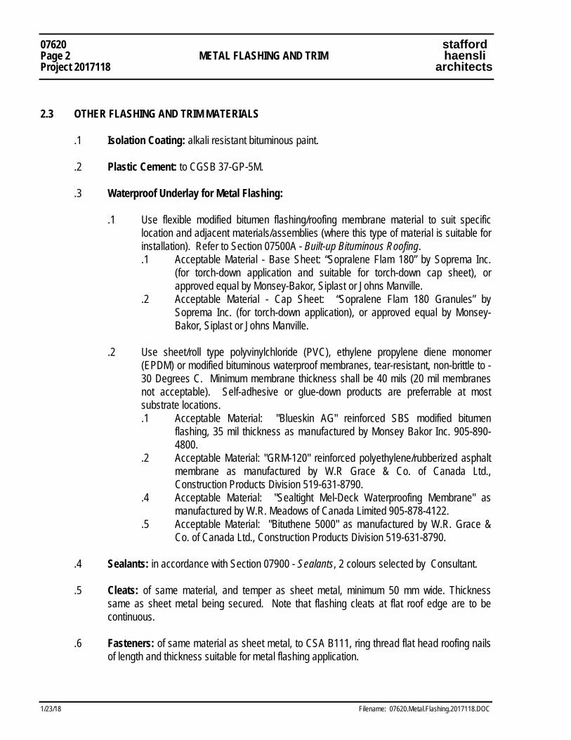
07620 stafford Page 2 METAL FLASHING AND TRIM haensli Project 2017118 architects
1/23/18 Filename: 07620.Metal.Flashing.2017118.DOC
2.3 OTHER FLASHING AND TRIM MATERIALS .1 Isolation Coating: alkali resistant bituminous paint. .2 Plastic Cement: to CGSB 37-GP-5M.
.3 Waterproof Underlay for Metal Flashing: .1 Use flexible modified bitumen flashing/roofing membrane material to suit specific
location and adjacent materials/assemblies (where this type of material is suitable for installation). Refer to Section 07500A - Built-up Bituminous Roofing.
.1 Acceptable Material - Base Sheet: “Sopralene Flam 180” by Soprema Inc. (for torch-down application and suitable for torch-down cap sheet), or approved equal by Monsey-Bakor, Siplast or Johns Manville.
.2 Acceptable Material - Cap Sheet: “Sopralene Flam 180 Granules” by Soprema Inc. (for torch-down application), or approved equal by Monsey-Bakor, Siplast or Johns Manville.
.2 Use sheet/roll type polyvinylchloride (PVC), ethylene propylene diene monomer
(EPDM) or modified bituminous waterproof membranes, tear-resistant, non-brittle to -30 Degrees C. Minimum membrane thickness shall be 40 mils (20 mil membranes not acceptable). Self-adhesive or glue-down products are preferrable at most substrate locations.
.1 Acceptable Material: "Blueskin AG" reinforced SBS modified bitumen flashing, 35 mil thickness as manufactured by Monsey Bakor Inc. 905-890-4800.
.2 Acceptable Material: "GRM-120" reinforced polyethylene/rubberized asphalt membrane as manufactured by W.R Grace & Co. of Canada Ltd., Construction Products Division 519-631-8790.
.4 Acceptable Material: "Sealtight Mel-Deck Waterproofing Membrane" as manufactured by W.R. Meadows of Canada Limited 905-878-4122.
.5 Acceptable Material: "Bituthene 5000" as manufactured by W.R. Grace & Co. of Canada Ltd., Construction Products Division 519-631-8790.
.4 Sealants: in accordance with Section 07900 - Sealants, 2 colours selected by Consultant. .5 Cleats: of same material, and temper as sheet metal, minimum 50 mm wide. Thickness
same as sheet metal being secured. Note that flashing cleats at flat roof edge are to be continuous.
.6 Fasteners: of same material as sheet metal, to CSA B111, ring thread flat head roofing nails
of length and thickness suitable for metal flashing application.
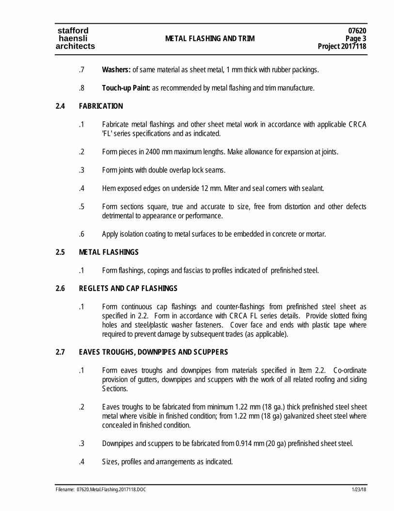
stafford 07620 haensli METAL FLASHING AND TRIM Page 3 architects Project 2017118
Filename: 07620.Metal.Flashing.2017118.DOC 1/23/18
.7 Washers: of same material as sheet metal, 1 mm thick with rubber packings. .8 Touch-up Paint: as recommended by metal flashing and trim manufacture. 2.4 FABRICATION .1 Fabricate metal flashings and other sheet metal work in accordance with applicable CRCA
'FL' series specifications and as indicated. .2 Form pieces in 2400 mm maximum lengths. Make allowance for expansion at joints. .3 Form joints with double overlap lock seams. .4 Hem exposed edges on underside 12 mm. Miter and seal corners with sealant. .5 Form sections square, true and accurate to size, free from distortion and other defects
detrimental to appearance or performance. .6 Apply isolation coating to metal surfaces to be embedded in concrete or mortar. 2.5 METAL FLASHINGS .1 Form flashings, copings and fascias to profiles indicated of prefinished steel. 2.6 REGLETS AND CAP FLASHINGS .1 Form continuous cap flashings and counter-flashings from prefinished steel sheet as
specified in 2.2. Form in accordance with CRCA FL series details. Provide slotted fixing holes and steel/plastic washer fasteners. Cover face and ends with plastic tape where required to prevent damage by subsequent trades (as applicable).
2.7 EAVES TROUGHS, DOWNPIPES AND SCUPPERS .1 Form eaves troughs and downpipes from materials specified in Item 2.2. Co-ordinate
provision of gutters, downpipes and scuppers with the work of all related roofing and siding Sections.
.2 Eaves troughs to be fabricated from minimum 1.22 mm (18 ga.) thick prefinished steel sheet
metal where visible in finished condition; from 1.22 mm (18 ga) galvanized sheet steel where concealed in finished condition.
.3 Downpipes and scuppers to be fabricated from 0.914 mm (20 ga) prefinished sheet steel. .4 Sizes, profiles and arrangements as indicated.
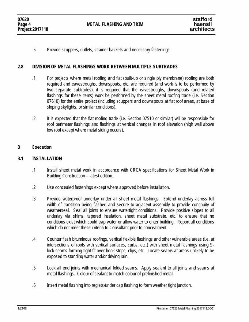
07620 stafford Page 4 METAL FLASHING AND TRIM haensli Project 2017118 architects
1/23/18 Filename: 07620.Metal.Flashing.2017118.DOC
.5 Provide scuppers, outlets, strainer baskets and necessary fastenings. 2.8 DIVISION OF METAL FLASHINGS WORK BETWEEN MULTIPLE SUBTRADES .1 For projects where metal roofing and flat (built-up or single ply membrane) roofing are both
required and eavestroughs, downspouts, etc. are required (and work is to be performed by two separate subtrades), it is required that the eavestroughs, downspouts (and related flashings for these items) work be performed by the sheet metal roofing trade (i.e. Section 07610) for the entire project (including scuppers and downspouts at flat roof areas, at base of sloping skylights, or similar conditions).
.2 It is expected that the flat roofing trade (i.e. Section 07510 or similar) will be responsible for
roof perimeter flashings and flashings at vertical changes in roof elevation (high wall above low roof except where metal siding occurs).
3 Execution 3.1 INSTALLATION .1 Install sheet metal work in accordance with CRCA specifications for Sheet Metal Work in
Building Construction – latest edition. .2 Use concealed fastenings except where approved before installation. .3 Provide waterproof underlay under all sheet metal flashings. Extend underlay across full
width of transition being flashed and secure to adjacent assembly to provide continuity of weatherseal. Seal all joints to ensure watertight conditions. Provide positive slopes to all underlay via shims, tapered insulation, sheet metal substrate, etc. to ensure that no conditions exist which could trap water or allow water to enter building. Report all conditions which do not meet these criteria to Consultant prior to concealment.
.4 Counter flash bituminous roofings, vertical flexible flashings and other vulnerable areas (i.e. at
intersections of roofs with vertical surfaces, curbs, etc.) with sheet metal flashings using S-lock seams forming tight fit over hook strips, clips, etc. Locate seams at areas unlikely to be exposed to standing water and/or driving rain.
.5 Lock all end joints with mechanical folded seams. Apply sealant to all joints and seams at
metal flashings. Colour of sealant to match colour of prefinished metal. .6 Insert metal flashing into reglets/under cap flashing to form weather tight junction.
stafford 07620 haensli METAL FLASHING AND TRIM Page 5 architects Project 2017118
Filename: 07620.Metal.Flashing.2017118.DOC 1/23/18
.7 Turn top edge of flashing into recessed reglet or mortar joint minimum of 19 mm. Lead wedge flashing securely into joint.
.8 Caulk flashing at reglet with sealant. END OF SECTION 07620
07620 stafford Page 6 METAL FLASHING AND TRIM haensli Project 2017118 architects
1/23/18 Filename: 07620.Metal.Flashing.2017118.DOC
This Page Intentionally Left Blank
stafford 07900 haensli SEALANTS Page 1 architects Project 2017118
Filename: 07900.Sealants.2017118.DOC 1/23/18
1 General
1.1 RELATED WORK .1 Section 07620 - Caulking in connection with roof flashing .2 Section 08020 - Caulking at Aluminum Doors, Frames, Windows, Curtain Walls and
Skylights .3 Section 08110 - Caulking at hollow metal frames and screens 1.2 SAMPLES .1 Submit duplicate samples of each type of material and colour to be used in accordance with
Section 01340 - Shop Drawings, product data, samples and mock-ups. 1.3 ENVIRONMENTAL CONDITIONS .1 Sealant and substrate materials to be minimum 5°C. .2 Should it become necessary to apply sealants below 5°C, consult sealant manufacturer and
follow their recommendations. 1.4 WARRANTY .1 The Warranty specified in the construction Contract shall be extended for the work of this
Section to a period of three (3) years from the date of Substantial Performance, for materials and workmanship.
.2 Contractor warrants that sealants will not leak, crack, crumble, melt, shrink, run, lose
adhesion or stain adjacent surfaces. 1.5 MANUFACTURER'S SAFETY DATA SHEETS .1 Refer to Section 01545 - Safety Requirements for information regarding Manufacturer's
Safety Data Sheets. Submit manufacturer’s Material Safety Data Sheets for all products specified in this Section.
07900 stafford Page 2 SEALANTS haensli Project 2017118 architects
1/23/18 Filename: 07900.Sealants.2017118.DOC
2 Products 2.1 MATERIALS .1 The products of the following manufacturers are approved for use subject to meeting the
specifications for the particular type of sealants listed below. However, this is not an approval to substitute another type of sealant for those specified:
.1 Tremco Ltd. .2 Canadian General Electric (CGE) Ltd. .3 Dow Corning Canada Ltd. .2 Primers: Type recommended by sealant manufacturer. .3 Joint Fillers:
.1 General: compatible with primers and sealants, outsized 30 to 50%. .2 Polyethylene, urethane, neoprene or vinyl: extruded closed cell foam, Shore A
hardness 20, tensile strength 140 to 200 kPa. .3 Neoprene or butyl rubber: round solid rod, Shore A hardness 70. .4 Polyvinyl chloride or neoprene: extruded tubing with 6 mm minimum thick walls.
.4 Bond Breaker: pressure sensitive plastic tape, which will not bond to sealants. .5 Sealants:
.1 General: Normal temperature range, dry conditions, movement range to 25%: Sealant for interior and exterior locations - two part epoxidized polyurethane polymer sealant with the following minimum properties:
.1 Movement Capacity +/- 25% .2 Adhesion in Peel 1.78 kg/cm (10 lbs./in.) .3 Shore A Hardness 25 – 30
.4 Acceptable Material: “Dymonic 100”; “Dymonic”; “Dymeric 240”; “Dymeric 240 FC”; also acceptable are silicone-based products (Tremco “Spectrum 3”; “Spectrum 4-TS”; “Tremsil 600”, etc.)
.2 Exterior Use: Sealants for exterior use to be custom coloured, matched to
Consultant's sample (two (2) exterior colours required for this project). .1 Acceptable Material: "Dymeric” by Tremco or “Sonolastic NP2” by
Sonneborn. .2 Acceptable Material: Premium commercial grade silicone based products for
exterior use, as manufactured by G.E. Silicones or Dow Corning Canada Ltd.
stafford 07900 haensli SEALANTS Page 3 architects Project 2017118
Filename: 07900.Sealants.2017118.DOC 1/23/18
.3 Traffic Bearing: Sealants for horizontal traffic bearing joints: .1 Normal temperature range, dry or wet conditions, movement range to 25%:
CAN2-19.24-M90. .2 Acceptable Material: "THC 900" by Tremco.
.4 Interior - Silicone: Sealants for interior locations where conditions of high humidity
exist (such as washrooms and shower rooms): one-part silicone conforming to CGSB 19-GP.22. These (silicone) sealants are also acceptable for interior general locations.
.1 Acceptable Material: "Tremsil 600" by Tremco. .2 Acceptable Material: Dow Corning 786, CGE 1702 Sanitary Sealant.
.5 Colour of Sealants: .1 Exterior: two (2), as selected from manufacturer's full range. .2 Interior: one (1), as selected from manufacturer's full range.
.6 Joint Cleaner: xylol, methylethylketone or non-corrosive type recommended by sealant manufacturer and compatible with joint forming materials.
.7 Vent Tubing: 3 to 6 mm inside diameter extruded polyvinyl chloride tubing.
.8 Joint Filler - Horizontal Locations: Closed cell, extruded polyethylene foam strips. .1 Acceptable Material: "HBR" Backrod by Tremco. .9 Joint Filler - Vertical Locations: Closed cell, extruded polyethylene foam strips. .1 Acceptable Material: "HBR" Backrod or "Sof-rod" by Tremco.
3 Execution 3.1 PREPARATION .1 Remove dust, paint, loose mortar and other foreign matter. Dry joint surfaces. .2 Remove rust, mill scale and coatings from ferrous metals by wire brush, grinding or
sandblasting. .3 Remove oil, grease and other coatings from non-ferrous metals with joint cleaner. .4 Prepare concrete, masonry, glazed and vitreous surfaces to sealant manufacturer's
instructions. .5 Examine joint sizes and correct to achieve depth ratio 1/2 of joint width with minimum width
and depth of 6 mm, maximum width 25 mm.
07900 stafford Page 4 SEALANTS haensli Project 2017118 architects
1/23/18 Filename: 07900.Sealants.2017118.DOC
.6 Install joint filler to achieve correct joint depth. .7 Where necessary to prevent staining, mask adjacent surfaces prior to priming and caulking. .8 Apply bond breaker tape where required to manufacturer's instructions. .9 Prime sides of joints in accordance with sealant manufacturer's instructions immediately prior
to caulking. 3.2 APPLICATION .1 Apply sealants, primers, joint fillers, bond breakers to manufacturer's instructions. Apply
sealant using gun with proper size nozzle. Use sufficient pressure to fill voids and joints solid. Superficial pointing with skin bead is not acceptable.
.2 Form surface of sealant with full bead, smooth, free from ridges, wrinkles, sags, air pockets,
embedded impurities. Neatly tool surface to a slight concave joint. .3 In masonry cavity construction, vent caulked joints from cavity to 3 mm beyond external face
of wall by inserting vent tubing at bottom of each joint and maximum of 1500 mm oc vertically. Position tube to drain to exterior.
.4 Clean adjacent surfaces immediately and leave work neat and clean. Remove excess sealant
and droppings using recommended cleaners as work progresses. Remove masking after tooling of joints.
3.3 LOCATIONS .1 Unless sealant is specified to be included in the Work of other sections, seal with exterior
sealant at the junction of the following exterior materials and surfaces plus at other locations where sealant is essential in maintaining the continued integrity of the air vapour barrier and watertight barrier:
.1 Concrete to metal .2 Concrete to masonry .3 Masonry to metal .4 Masonry to masonry and concrete .5 Metal to metal .6 Junctions of foundation walls and footings. .7 Around pipes and services entering through unit masonry and concrete foundation
walls .8 Perimeter of steel frames, metal panels, thresholds, framed openings .9 Perimeter junction of hollow metal frames and screens occurring in Masonry
Construction, on both sides to walls
stafford 07900 haensli SEALANTS Page 5 architects Project 2017118
Filename: 07900.Sealants.2017118.DOC 1/23/18
.10 Perimeter of louvres, mechanical hoods, ducts, etc. occurring in or extending through exterior walls
.11 At expansion joints .12 At control joints full height in masonry construction
.13 At joints between exterior panels. .2 Seal at the junction of the following interior materials and surfaces using interior sealant
specified unless covered by trim, or unless sealant is specified to be included in other sections.
.1 Concrete to metal .2 Concrete to masonry and precast concrete .3 Masonry to metal .4 Masonry and precast concrete to masonry and precast concrete .5 Metal to metal .6 Metal to drywall .7 At junctions full height of intersecting interior masonry walls including at angular
corners .8 Around pipes and services entering through unit masonry and concrete foundation
walls .9 Perimeter of steel frames, metal panels, thresholds, framed openings .10 Perimeter junction of hollow metal frames and screens occurring in Unit Masonry
Construction, on both sides to walls .11 At junctions of millwork (cabinets, countertops other than vanities, etc.) and adjacent
walls which they touch. .12 At junction of Stair Treads (finishes) and Stair Stringers. .13 At Junction of Water Closets, Urinals and the walls and/or floors which they touch. .14 At junction of wall-mounted lavatories (sinks) and adjacent walls which they touch.
.3 Seal with mildew resistant silicone sealant at the following interior locations:
.1 At junction between vanity counters and adjacent substrate with neat 3 mm bead. .2 Around access panels in ceramic tile faced walls with a neat 3 mm bead.
END OF SECTION 07900

07900 stafford Page 6 SEALANTS haensli Project 2017118 architects
1/23/18 Filename: 07900.Sealants.2017118.DOC
This Page is Intentionally Left Blank
stafford 07950 haensli AIR LEAKAGE SEALANT Page 1 architects Project 2017118
Filename: 07950.AirLeakSealant.2017118.DOC 1/23/18
1 General 1.1 RELATED WORK .1 Section 05300 - Steel Deck .2 Section 07900 - Sealants .3 Section 08020 - Aluminum Windows and Doors .4 Section 08110 - Hollow Metal Doors and Frames 1.2 STANDARDS .1 Refer to Ontario Building Code, latest edition and revision. 1.3 SAMPLES .1 Submit samples and manufacturer’s Product Data Sheets in accordance with Section 01340 -
Shop Drawings, Product Data, Samples And Mock-Ups. .2 In lieu of samples and testing procedures required by C.G.S.B. Specifications, submit
manufacturer's name for materials to be supplied for Project with manufacturer's affidavits that they meet applicable C.G.S.B. Specification. Submit in accordance with Section 01340 - Shop Drawings, Product Data, Samples And Mock-Ups.
.3 Submit material safety data sheets (MSDS) for all materials specified in this Section. 2 Products 2.1 MATERIALS .1 Air Leakage Sealant: One or two part liquid system dispensed from aerosol cylinders with
density of 225 P.F.C., R factor of 5.7 per 25 mm (1 in) thickness, compressive modules of 170-340 (parallel to rise).
.1 Acceptable Material: “Enerfoam/Foamitt” single component foam as manufactured by Abisko Manufacturing Inc. 416-259-3264.
.2 Acceptable Material: “Insta-Foam” as manufactured by Insta-Foam Products Inc. 416-622-6844.
.2 Materials by other manufacturers may be considered upon submission of full product data.
07950 stafford Page 2 AIR LEAKAGE SEALANT haensli Project 2017118 architects
1/23/18 Filename: 07950.AirLeakSealant.2017118.DOC
.3 Products to be supplied and installed under this Section are to be of such a type to be acceptable for use in ceiling spaces used as return air plenums in buildings of Non-Combustible Construction as classified by the Ontario Building Code. Review proposed product types, location and amounts of sealant material with the local Building Inspector prior to use. If materials are not acceptable when installed alone in ceiling spaces described above and/or at fire rated location, use an alternate approved material or supply a covering of approved material to protect Air Leakage Sealant at no additional cost to the Owner.
3 Execution 3.1 INSTALLATION .1 Examine joints before sealing to ensure that Configuration, surfaces, and widths are suitable
for sealant and service and that execution of sealing and performance of sealant will not be adversely affected. Defective work resulting from application to unsatisfactory joint conditions will be considered the responsibility of those performing the work of this Section.
.2 Proceed with air sealant only when air, substrate and surfaces in contact with air sealant are
completely dry. .3 Prepare joints by brushing, scrubbing, scraping or grinding inner surfaces to remove loose
mortar, dust, oil, grease, oxidation, mill scale, and other materials which will affect adhesion and integrity of sealant, and dry with clean cloths. Ensure that surfaces have not been coated with releasing agents, coating or other treatments, or that they are entirely removed.
.4 Finished joints to be free of air pockets, imbedded foreign materials and cut back after curing
to be flush with surrounding materials. .5 Do not allow sealants to cover or spot surfaces outside of joints. Use masking tape to
prevent, if necessary. .6 Where air leakage sealant is to be applied at edges of insulation or at air/vapour barrier
ensure that sealant is located to form seal at warm side of insulation and/or to form continuation of air/vapour barrier.
.7 Where air leakage sealant is to be faced by other caulking materials for finishing purposes,
ensure sealant is cut back or recessed to sufficient depth for finishing caulking.

stafford 07950 haensli AIR LEAKAGE SEALANT Page 3 architects Project 2017118
Filename: 07950.AirLeakSealant.2017118.DOC 1/23/18
3.2 LOCATIONS .1 Install air leakage sealant at all joints where air leakage may occur due to incomplete seal
between air barrier and adjacent components. Exact extent will vary depending upon installation methods used by various subtrades. Locations which may require air leakage sealant include, but are not limited to the following:
.1 Between door frames and adjacent walls. .2 Between window and curtain wall frames and adjacent walls. .3 Around electrical boxes, conduit, panels, etc. which penetrate air or vapour barriers. .4 Around mechanical pipes & fittings which penetrate air or vapour barriers. .5 Along the top of exterior walls and at wall plates, underside of slabs, precast slabs,
metal decks, etc. where opposite side of joint assembly is not fully sealed with an air barrier.
.6 Around structural beams, columns, joists, trusses, shoes, plates, etc. where structural elements penetrate air or vapour barriers.
.7 At all other locations indicated on drawings where air leakage sealant is specified. .8 At vertical corners of masonry cavity walls - to seal off cavity at right angled corners
to prevent air and/or pressure leaks between building faces/planes. 3.3 CLEANING .1 Remove from surfaces of other work sealant smears, droppings and masking tape
immediately after sealant has cured to a hard surface film. .2 Clean surfaces soiled by work of this Section. Do not use cleaning methods that will damage
surrounding surfaces. Make good work cleaning has damaged under work of this Section. END OF SECTION 07950
07950 stafford Page 4 AIR LEAKAGE SEALANT haensli Project 2017118 architects
1/23/18 Filename: 07950.AirLeakSealant.2017118.DOC
This Page is Intentionally Left Blank
stafford 08110 haensli STEEL HOLLOW METAL Page 1 architects DOORS, FRAMES AND SCREENS Project 2017118
Filename: 08110.HM.Doors.Frames.2017118.doc 1/23/18
1 General 1.1 RELATED WORK .1 Section 04000 - Masonry Procedures - Building-in and grouting frames in masonry .2 Section 06100 - Rough Carpentry - Building-in frames into wood stud walls .3 Section 07900 - Sealants - Caulking of joints between frames and other building components .4 Section 08710 - Finish Hardware .5 Section 08800 - Glazing .6 Section 09910 - Painting and Finishing 1.2 REFERENCE STANDARDS AND REQUIREMENTS
.1 ANSI/DHI A115.1G: Door and Hardware Institute “Installation Guide for Doors and Hardware” .2 ANSI/DHI A115 Series: Door and Hardware Institute “Hardware Preparations for Steel
Doors”. .3 ASTM A924(M): American Society for Testing and Materials “Sheet Steel, Metallic-Coated by
the Hot-Dip Process…”. .4 ASTM A653(M): American Society for Testing and Materials “Sheet Steel, Zinc-Coated by
Hot-Dip Process…”. .5 ASTM E90(M): American Society for Testing and Materials “… Laboratory Measurement of
Airborne Sound Transmission Loss…”. .6 CAN4-S105-M: “Standard Specification for Fire Doors and Frames Meeting Performance
Required by CAN4-S104”. .7 CSDFMA-08100: Canadian Steel Door and Frame Manufacturers Association “Specifications
for Commercial Steel Doors and Frames – 08100”. .8 CSDFMA-08100: Canadian Steel Door and Frame Manufacturers Association
“Recommended Dimensional Standards for Commercial Steel Doors and Frames – 08100”. .9 NFPA 80: National Fire Prevention Association “Standard for Fire Doors and Fire Windows”.
1.3 QUALITY ASSURANCE .1 Supply all steel door and frame product from one manufacturer member company of the
CSDFMA.
08110 stafford Page 2 STEEL HOLLOW METAL haensli Project 2017118 DOORS, FRAMES AND SCREENS architects
1/23/18 Filename: 08110.HM.Doors.Frames.2017118.doc
.2 CSDFMA-08100 “Specifications for Commercial Steel Doors and Frames – 08100” shall be the minimum fabrication standard for the work of this Section, except where more stingent requirements are listed herein.
.3 A Cash Allowance sum is included in the project Cash Allowance for the inspection of product
and installation of the work of this Section of same at the time of Substantial Performance.
1.4 SHOP DRAWINGS .1 Submit shop drawings in accordance with Section 01340 - Shop Drawings, Product Data,
Samples And Mock-Ups. .2 Indicate each type frame material, core thickness, reinforcements, glazing stops, location of
anchors and exposed fastenings, finishes and fire ratings. .3 Fire Ratings indicated on Door Finish Schedule are minimums. If door design cannot be
satisfied at specified rating (i.e. 20 min.), supply door or frame with acceptable higher rating (i.e. 45 min.).
.4 Indicate hardware mounting heights on shop drawings on a door-by-door basis. The Owner’s
requirements for mounting heights for door hardware are indicated on the drawings, detail sheets and in the specifications. These requirements must be followed and are not negotiable.
5. Contractor to provide one (1) full sized Hollow Metal Door & Frame for approval, before
production of remainder of products for this project. The sample “approval” door and frame may be built-into the project, once approved.
1.5 WARRANTY
.1 Extend the warranty specified in construction contract for work of this Section, for material, workmanship, repair and/or replacement of defective work, and against defects and malfunction, to a period of three (3) years from the date of Substantial Performance.
2 Products 2.1 MATERIALS .1 Steel Sheet: commercial grade steel to ASTM A924(M97), hot dip galvanized to ASTM
A653(M97), Type B, coating designation ZF75, known commercially as paintable “Galvanneal” as follows:
stafford 08110 haensli STEEL HOLLOW METAL Page 3 architects DOORS, FRAMES AND SCREENS Project 2017118
Filename: 08110.HM.Doors.Frames.2017118.doc 1/23/18
.1 Exterior doors and frames: to minimum coating designation of ZF75, galvannealed, 1.6 mm (16 ga) base thickness steel sheet (doors and frames).
.2 Interior doors and frames: to minimum coating designation of ZF75 , galvannealed, 1.6 mm (16 ga) base thickness steel sheet for frames; 1.22 mm (18 ga) base thickness sheet steel for doors.
.3 Floor anchors, channel spreaders and wall anchors: 1.6 mm (16 ga) base thickness steel sheet.
.4 Guard boxes: 1.22 mm (18 ga) base thickness steel sheet. .5 Glazing stops: 1.22 mm (18 ga) base thickness steel sheet, screw fixed tamperproof. .6 Hinge Reinforcement: 3.5 mm (10 ga) base thickness steel sheet. .7 Closer pieces: 1.22mm (18 ga) base thickness sheet steel.
.2 Knock-Down Frames: not permitted for use on this project. .3 Reinforcing Channel: to CAN3-G40.20, type 300W, 0.91 mm (20 ga). .4 Door Bumpers: black neoprene single stud. .5 Door Core:
.1 Honeycomb: structural small cell honeycomb core consisting of pre-expanded, resin impregnated, kraft paper having 20 mm cell size to thickness indicated:
.1 Not applicable to this project. .2 Hollow steel: vertically stiffened with steel ribs and all voids filled with semi- rigid
fibrous insulation minimum density 24kg/m3 polystyrene polyurethane: Interior “high traffic” designated doors – as follows: .1 Exterior doors .2 Stairwell doors .3 Cross-corridor doors .4 Other doors designated “High Traffic Door” (HTD) on Door Finish Schedule.
.3 Hollow steel: vertically stiffened with steel ribs and all voids filled with semi- rigid fibrous insulation minimum density 24kg/m3 polystyrene polyurethane: Exterior doors-all locations.
.4 Fire rated doors: in accordance with registered fire tests for doors of that size and rating.
.6 Primer: for touchup to CGSB 1-GP-181M. .7 Frame and screen anchors: supply appropriate type of anchors to suit adjacent construction
and in accordance with NFPA 80 where applicable (fire rated frames). Most locations for this project will require wire-type masonry anchors for building into mortar joints by masonry trades. These anchors to be 4.0mm diameter, hot dipped galvanized, pre-formed for snap-in assembly. Supply a minimum of three (3) anchors for each jamb.
08110 stafford Page 4 STEEL HOLLOW METAL haensli Project 2017118 DOORS, FRAMES AND SCREENS architects
1/23/18 Filename: 08110.HM.Doors.Frames.2017118.doc
.8 Acceptable Manufacturers: SW Fleming Ltd., Baron Metal Industries Inc. or Trillium Steel Door Ltd.
2.2 FABRICATION .1 Fabricate steel doors and frames as detailed, to Canadian Steel Door and Frame
Manufacturers' Association, (CSDFMA) "Canadian Manufacturing Specifications for Steel Doors and Frames", latest edition, plus add more stringent requirements specified in this Section.
.2 Doors and Frames – Finish Hardware: Reinforce frames to suit finish hardware
requirements specified Section 08710 - Finish Hardware. Reinforce all door frames to accept continuous hinges where these types of hinges are specified. Template cut and weld in place at doors and/or frames (as applicable) reinforcing plates and boxes to accept butt hinges, strikes, door closers, overhead stop arms and any other specialty hardware specified. Install electrical boxes at frame jambs and/or heads to suit electronic finish hardware devices specified. Minimum thicknesses of reinforcing devices to be as follows:
.1 Butt hinge reinforcements: 3.0 mm (10 ga.) thick hinge plates, with integral high frequency angle – to suit heavy weight hinges – applies to both doors and frames.
.2 Continuous hinge reinforcements: 2.7 mm thick continuous reinforcement, in both doors and frames.
.3 Mortise lock reinforcements: 1.22 mm (18 ga.) thick reinforcing box, with integral lock-edge mounting tabs and lock body support.
.4 Cylindrical lock reinforcements: 1.22 mm (18 ga.) thick reinforcing, with integral lock-edge mounting tabs and latch case support.
.5 Door closers, door stop-arms, door pulls, push bars: 1.6 mm (16 ga.) reinforcing at attachment locations and “spreader plates” at all through-bolt locations (to avoid pinching of door at time of installation).
.6 Provide all function holes for all latching and locking hardware, including those for all through-bolted trim.
.7 Factory mortise, reinforce, drill and tap all preparations for mortised template hardware. Site-drill and tap for installation of surface-applied hardware, in accordance with hardware manufacturer’s installation templates.
.3 Frames: Cut mitres and joints accurately and weld continuously on inside of frame profile.
Note that both 50 mm (2.0 in.) and 38 mm (1.5 in.) frame widths are required for this Project. Note also that 150 mm and 200 mm (nominal) frame depths are required for this project. Refer to Frame Types Drawings.
.4 Frames/Screens: Continuously weld all joints at intersections of vertical and horizontal
frame/screen members, both at perimeter frame and at intermediate mullions. Assemble mullions in accordance with CAN4-S105, Figure 4, as the minimum acceptable construction. Include 20 gauge continuous internal reinforcing channel for full length of mullions.

stafford 08110 haensli STEEL HOLLOW METAL Page 5 architects DOORS, FRAMES AND SCREENS Project 2017118
Filename: 08110.HM.Doors.Frames.2017118.doc 1/23/18
.5 Frames: Grind all welded corners and joints in flat plane, fill with metallic paste filler and sand to uniform smooth finish.
.6 Frames/Screens: Reinforce heads of frames wider than 1200 mm. Reinforce heads of
frames/screens wider than 1800 mm and jambs of frames/screens where indicated with 100 mm x 40 mm galvanized structural steel channel. For jamb reinforcing install continuous from floor to structure above.
.7 Frames/Screens: Reinforce heads of frames to accept removable mullions, where indicated
to be supplied by Finish Hardware Supplier (Section 08710, 08712). Please note that all removable mullions are to be fire rated, heavy duty tubular section steel type, reinforced. Aluminum mullions will not be utilized on this project.
.8 Doors: Doors shall be flush with no face seams. Doors to have vertical, mechanically
interlocked and continuously welded seams on hinge and lock edges. Door skins to be laminated to door core using UL listed adhesive compatible with core materials (steel stiffeners at door requiring same are to be welded in place). Honeycomb cores and insulation (between steel stiffeners) shall completely fill void area within doors.
.9 Fire Rated Doors, Frames, Screens: Fabricate doors, frames and screens in accordance
with labelling authority’s requirements. Provide Temperature Rise Rated (TRR) doors and frames where so indicated.
.10 Doors: Doors shall be fitted with 1.6 mm (16 ga.) steel end channels projection welded to top
and bottom of door. All exterior doors to be fitted with flush steel top caps. .11 Touch up doors and frames with zinc rich primer where galvanized finish is damaged during
fabrication. .12 Doors and Frames: Provide glazing stops for glazed openings indicted at doors, frames and
screens. Fabricate stops to form neat corner joints, free from gaps. All stops resulting in gaps greater than 1 mm in final, installed position will be rejected and must be replaced.
.13 Door Bumpers: Install 3 bumpers on strike jamb for each single door plus 2 bumpers at
head for pairs of doors. Provide a minimum of fifty (50) spare door/frame bumpers to Owner at end of construction for replacement of bumpers in future – spare units supplied shall not be used by Contractor to complete the project work or to correct deficient work.
.14 Preparation for Finish Hardware:
.1 Refer to Finish Hardware Schedule as provided either a) at the time of tender or b) the first schedule released by the Consultants following tender, whichever comes first.
.2 Mortise, reinforce, drill and tap doors and reinforcements to receive hardware using templates provided by finish hardware supplier.
08110 stafford Page 6 STEEL HOLLOW METAL haensli Project 2017118 DOORS, FRAMES AND SCREENS architects
1/23/18 Filename: 08110.HM.Doors.Frames.2017118.doc
.3 Provide all reinforcing plates, special routings, backing plates, mortar boxes, etc. all as required to allow proper mounting of finish hardware following installation of frames (including filling all frames with mortar).
.4 At all doors/frames indicated to have electric strikes and/or electric transfer hinges and/or electric locksets and/or electric exit devices provide from the factory welded boxes to receive electrical device(s) plus 13 mm metal conduit from boxes to top corner of door frame (to receive low voltage wiring by others). If arrangement of box(es) and/or conduit is not clear, request clarification from Consultant prior to fabrication. Suitable diagrams will be issued.
.15 Provide adjustable jamb anchors for fixing at floors. .16 Make provision for louvres and glazing as indicated and provide necessary glazing stops. .17 Construct rail and stile doors in same manner as flush doors. .18 Provide all hollow metal closure pieces indicated. Installation (where feasible) is to be done
at time of frame/screen fabrication, attached to such surfaces so as to allow proper assembly and alignment on site. Include anchors, clip angles, flanges, return edges, etc. to facilitate final connections on site.
.19 All Removable Mullions are to be Reinforced, Hollow Metal. 3 Execution 3.1 INSTALLATION .1 Set frames plumb, square, level and at correct elevation. .2 Secure anchorages and connections to adjacent construction. Provide a minimum of three
(3) anchors per jamb but anchors not to exceed 800 mm on centre. Install anchors adjacent to all hinge and latch/lock locations
.3 Brace frames rigidly in position while building-in. Install temporary horizontal wood spreader
at third points of door opening to maintain frame width. Provide vertical support at centre of head for openings over 1200 mm wide. Remove temporary spreaders after frames are built-in.
.4 Install fire rated doors and frames in accordance with National Fire Codes, Volume 4,
produced by National Fire Protection Association (NFPA 80).

stafford 08110 haensli STEEL HOLLOW METAL Page 7 architects DOORS, FRAMES AND SCREENS Project 2017118
Filename: 08110.HM.Doors.Frames.2017118.doc 1/23/18
.5 Fill all frames and screens located at masonry walls completely with mortar or grout. Frames and screens at stud construction to be fitted with continuous adjustable tension anchor strips.
.6 Installation or final assembly of closure pieces, when done on site, to be done using welding
techniques or concealed fasteners. Perform work in such a manner to achieve smooth, even, neat finished appearance. Grind all welds smooth and prime. Exposed fasteners, where permitted, are to be flush head type.
.7 Attach fire rating labels to doors and frames required to be fire rated. Ratings shown on door
schedule are minimum. .8 Make allowances for deflection of structure to ensure structural loads are not transmitted to
frames. .9 Install doors and hardware in accordance with hardware templates and manufacturer's
instructions and Section 08710 - Finish Hardware. .10 Adjust operable parts for correct function. .11 Install door louvres where indicated. END OF SECTION 08110

08110 stafford Page 8 STEEL HOLLOW METAL haensli Project 2017118 DOORS, FRAMES AND SCREENS architects
1/23/18 Filename: 08110.HM.Doors.Frames.2017118.doc
This Page is Intentionally Left Blank
stafford 08800 haensli MISCELLANEOUS Page 1 architects GLASS AND GLAZING Project 2017118
Filename: 08800.MiscGlass.2017118.DOC 1/23/18
1 General 1.1 WORK INCLUDED .1 Work of this Section includes, but is not limited to: .1 Glazing of steel hollow metal doors, frames and screens .2 Glazing of wood doors and/or plastic faced wood doors .3 Glazing at miscellaneous locations, such as display cases, glass shelves, etc. -
except as noted in item 1.2 below .4 Glazing at mirrors - except as noted in item 1.2 below 1.2 WORK NOT INCLUDED .1 Work of this Section specifically does not include: .1 Glazed cabinet doors specified and detailed as part of millwork cabinetry - these
items supplied as part of the work of Section 06400. .2 Manufactured items which include glass as part of the manufactured assembly (such
as manufactured display board units where glass is included at hinged cover frame - these items specified in Division 10)
.3 Manufactured items which include mirrors as part of the manufactured assembly (such as special tilting mirrors for handicapped lavatory locations, medicine cabinet doors, etc. - these items specified in Section 10800) - note that standard metal-framed fixed mirrors are to be provided by this Section.
.4 Mounting hardware for sliding glass doors, adjustable glass shelves and other similar items at display cases (this hardware is specified in either Section 06400 or 08710)
1.3 RELATED WORK .1 Section 08020 - Aluminum Doors, Windows and Curtain Walls .2 Section 08110 - Steel Hollow Metal Doors, Frames and Screens .3 Section 10800 - Toilet and Bath Accessories - Manufactured Mirror Products 2 Products 2.1 GLASS MATERIALS .1 Polished Plate or Float Glass: to CAN/CGSB-12.3, glazing quality. Thickness: 6 mm.
Identified as “PG” on drawings and schedules. .2 Fire Rated Glass: to CAN/CGSB-12.1-2017,
1. Fire protection rated, impact resistant, laminated clear glass ceramic; in all frames/screens and doors where fire rated separations are required: Thickness: 6 mm. Identified as “FPG” or “FG” on drawings and schedules.
.1 Firelite Plus” by Technical Glass Products, “Pyran Platinum L” by
08800 stafford Page 2 MISCELLANEOUS haensli Project 2017118 GLASS AND GLAZING architects
1/23/18 Filename: 08800.MiscGlass.2017118.DOC
Schott North America, or “Keralite Select L” by Vetrotech Saint-Gobain.
.2 Fire rated glass must bear a permanent label acceptable to local Authorities having jurisdiction.
.3 Coordinate with manufacturer of hollow metal products to ensure the glass provided is an acceptable component in their labelled door and frames.”
.3 Safety Glass (Tempered): to CAN/CGSB-12.1, Type 2, Class “B”, fully tempered float glass,
glazing quality, all edges ground and polished. Thicknesses: 6 mm, 8 mm or 12mm. Identified as “TPG” on drawings and schedules.
.4 Safety Glass (Laminated): to CAN/CGSB-12.1, laminated float glass consisting of two layers
of heat strengthened glass plus a fully laminated vinyl interlayer, glazing quality, all edges ground and polished. Thickness: 6 mm (overall - nominal). Identified as “LPG” on drawings and schedules.
.5 Heat Strengthened Glass: to CAN/CGSB-12.1 and ASTM C 1036-85 and ASTM C 1048-
85, polished float glass with heat strengthening treatment, glazing quality. Thickness: 6 mm. Identified as “HSG” on drawings and schedules.
.6 Mirrored Glass: to CAN/CGSB-12.5, Type 1A, silvered clear float glass, all edges ground
and polished. Thickness : 6 mm. .7 Metal Framed Mirrors: mirrored glass as specified in 2.1.5 above, complete with stainless
steel channel frame edging, all corners mitred and secured with concealed fasteners. Framed mirrors to include concealed mounting clips to allow secure wall mounting with no exposed fasteners in finished condition. Stainless steel to be Type 304 with No. 4 (brushed) finish.
.1 Sizes and Locations: Refer to drawings, AD Drawings, Schedules and finish notes. 2.2 GLAZING AND SEALING COMPOUND MATERIALS .1 Glazing Tape: preformed, pre-shimmed butyl tape, 10-15 durometer hardness, paper release,
width and thickness to suit location. .2 Setting Blocks: neoprene, Shore "A" durometer hardness 80, 100 mm long x 6 mm high x
width to suit glass thickness. .3 Spacers and (Spacer) Shims: neoprene, Shore "A" durometer hardness 40-60, 75 mm long x
2.4 mm thick x 9 mm high. .4 Resilient Channel Gasket: Extruded neoprene or PVC channel gaskets, sized and
manufactured specifically for glazing purposes.
stafford 08800 haensli MISCELLANEOUS Page 3 architects GLASS AND GLAZING Project 2017118
Filename: 08800.MiscGlass.2017118.DOC 1/23/18
.5 Mirror Adhesive: "Mirror Mastic" adhesive as manufactured by Palmer Asbestos and Rubber Corporation. Material to be asbestos-free.
.6 Primer-Sealers and Cleaners: to glass manufacturer's standard. 3 Execution 3.1 WORKMANSHIP - GENERAL .1 Remove protective coatings and clean contact surfaces with solvent and wipe dry. .2 Unless noted otherwise, all interior clear glazing shall be 6 mm tempered plate glass (6TPG). .3 Unless noted otherwise all interior clear glazing is to be dry glazed (using resilient channel
gasket, not glazing tape/glazing sealant/compound). .4 Apply primer-sealer to contact surfaces where glazing compounds/tapes are to be employed. .5 Place setting blocks as per manufacturer's instructions. Use minimum of two setting blocks,
spaced at quarter points across lower edge (setting blocks to be not more than 800 mm apart). Locate spacers at jamb edges of glass, uniformly spaced and not more than 600 mm o.c. from top to bottom.
.6 Install glass, rest on setting blocks, ensure full contact and adhesion at perimeter. .7 Install removable stops, installed to final locations and secure stops without displacing tape or
sealant (where present). .8 Provide edge clearance of 3 mm minimum. .9 Insert (spacer) shims to center glass in space. Place shims at 600 mm o.c. and keep 6 mm
below sight line. .10 Do not cut or abrade tempered, heat treated, coated or special textured glass. .11 Provide adequate edge clearances for glazing sheets in accordance with manufacturer's
instructions. 3.2 EXTERIOR GLAZING (HOLLOW METAL WORK) .1 Combination Method - Tape/Sealant:
.1 Cut glazing tape to proper length and set against permanent/fixed (exterior) stops, 6.0 mm below sightline. Install horizontal strips first, extend over entire width of
08800 stafford Page 4 MISCELLANEOUS haensli Project 2017118 GLASS AND GLAZING architects
1/23/18 Filename: 08800.MiscGlass.2017118.DOC
opening before applying vertical strips. Weld corners together by butting tape and dabbing with sealant.
.2 Place glazing tape on free perimeter of glass in same manner described above but top edge of tape to be 3.0 mm below sightline.
.3 Install removable (interior) stops, compressing both layers of glazing tape. Trim glazing tape at removable (inner) stop to neat, even edge 1.0 mm below sightline.
.4 Fill gap between glass and fixed (outer) stop with neat bead of sealant to full depth of gap. Tool exposed edge of sealant to neat, even, sloped bead designed to shed water.
3.3 INTERIOR GLAZING .1 Dry Method - Resilient Channel Gasket:
.1 Prior to setting glass, install channel gasket around entire perimeter of glass. Make tight butt joints at corners.
.2 Place glass unit on setting blocks at sill and attach spacers at sides to centre unit in frame opening.
.3 Install removable stop, compressing gasket evenly. Adjust and/or re-install stops until even compression and appearance is achieved.
.2 Fire Rated Assemblies: .1 Set glass on continuous setting blocks. Install spacers as required to centre glass in
opening. .2 Embed glass edges in putty in accordance with NFPA 80 requirements for fire rated
assemblies. .3 Install stops to even gap, each side of glass. All exposed joints between metal, putty
and glass shall be struck and pointed to a smooth, uniform sightline. .4 Protect putty from physical damage or defacement until fully set and tack-free.Fire
protection rated applications, all glazing accessories at fire rated glass shall be as specified in the cUL or ULC tested assemblies for the specific glass type.
.5 Install fire rated glazing to be installed in all rated doors and screens. .6 Install fire rated glass so that the appropriate rating marking remains permanently
exposed. .7 Install fire rated glass vertically into fire rated frames. Glass and frames shall be
equivalent fire separation rating. .8 Products and installation shall be in accordance with tested assemblies: ULC or cUL,
or equivalent acceptable to authorities having jurisdiction. .9 Apply glazing tape to stops, using tape thickness to suit installation, flush with site
lines, with stretch allowance consideration. .10 Centre glass in opening and set on setting blocks located at quarter points of glass
but no more than 150mm from corners. .11 Install glass, glazing tap and removable stops.
stafford 08800 haensli MISCELLANEOUS Page 5 architects GLASS AND GLAZING Project 2017118
Filename: 08800.MiscGlass.2017118.DOC 1/23/18
3.4 MIRROR INSTALLATION .1 Install frameless mirrors where indicated using full adhesive bed. .2 Install metal framed mirrors using concealed mounting clips. Adhesive may be used to
augment (but not replace) clip mounting. 3.5 GLASS SLIDING DOORS (Display Cases, Etc. – Where So Indicated) .1 Precisely site-measure display case (or similar) opening requirements prior to fabricating
glass. Make allowances for required overlaps to accommodate locking devices. .2 Obtain manufacturer's instructions and/or measured dimensions of sliding track hardware to
determine proper clearances and glass sizing. .3 Cut glass sizes to suit. Drill any holes required for final installation. grind all edges smooth
and slightly rounded. Temper glass after all fabrication is complete. .4 Install glass doors in fitments with (or secured by) hardware, tracks, stops, brackets, etc.
supplied by other Sections. 3.6 FINISHING .1 Immediately remove sealant and compound droppings from finished surfaces. Remove labels
after work is completed. 3.7 CLEANING .1 Before building is turned over to Owner, remove temporary protection, clean and polish all
glass and frame surfaces. .2 Recheck all glazing tape and sealants to ensure that neat, even sightlines are present.
Repair, trim, replace any improperly installed tape or sealant. .3 Remove any foreign material (sealant, etc.) from glass and frame surfaces during cleaning
operations. END OF SECTION 08800
08800 stafford Page 6 MISCELLANEOUS haensli Project 2017118 GLASS AND GLAZING architects
1/23/18 Filename: 08800.MiscGlass.2017118.DOC
This Page Intentionally Left Blank
stafford 09250 haensli GYPSUM BOARD Page 1 architects Project 2017118
Filename: 09250.GypsumBoard.2017118.DOC 1/23/18
1 General 1.1 RELATED WORK .1 Section 05410 - Load-Bearing Metal Stud Systems .2 Section 06100 - Rough Carpentry .3 Section 07190 - Air and Vapour Barriers .4 Section 07210 - Batt and Blanket insulation .5 Section 09110 - Non Load-Bearing Metal Stud Systems - metal studs and furring 1.2 REFERENCE STANDARDS .1 Do work in accordance with CSA A82.31 except where specified otherwise. 1.3 SAMPLES .1 Submit samples in accordance with Section 01340 - Shop Drawings, Product Data, Samples
and Mock-Ups. .2 Submit duplicate 300 x 300 mm size samples of vinyl faced gypsum board and 300 mm long
samples of corner and casing beads for standard gypsum board. 1.4 QUALITY STANDARDS - FINISHING .1 All gypsum board work is to be fully finished and sanded, ready for paint by this Section.
Consultant is to be notified in advance of start of priming / painting / coating operations to allow for inspection.
.2 Consultant will review the finished gypsum board work OR Consultant will designate specialty
inspection and testing services to make such inspection. .3 Following gypsum board review / inspection Contractor shall correct all deficiencies noted
prior to proceeding with painting / coatings work. Consultant may re-review / re-inspect if necessary.
.4 Failure to follow the above-noted procedures may result in additional corrective work being
required of the Contractor and/or Subcontractor. No consideration will be granted for extra Contract Time and/or payments for such corrective work.
09250 stafford Page 2 GYPSUM BOARD haensli Project 2017118 architects
1/23/18 Filename: 09250.GypsumBoard.2017118.DOC
2 Products 2.1 GYPSUM BOARD .1 Plain Gypsum Board (GB): to CSA A82.27 standard type 12.7 mm (1/2 in.) thickness, 1220
mm (48 in.) wide sheets x maximum practical length, ends square cut, edges tapered and rounded. Use 12.7 mm (1/2 in.) thickness unless specified otherwise.
.2 Plain Gypsum Board – Ceiling Board (GB-C): to CSA A82.27 increased stiffness type 12.7
mm (1/2 in.) thickness, 1220 mm (48 in.) wide sheets x maximum practical length, ends square cut, edges tapered and rounded. Use 12.7 mm (1/2 in.) thickness unless specified otherwise.
.3 Fire Rated Gypsum Board (GB or GB-FR): to CSA A82.27, fire rated Type X, 15.9 mm (5/8
in.) and 12.7 mm (1/2 in.) thickness, 1220 mm (48 in.) wide sheets x maximum practical length, ends square cut, edges tapered and rounded. Use 15.9 mm (5/8 in.) thickness unless specified otherwise. Refer to ULC assembly rating requirements and to National Building Code Supplement for fire resistance ratings, thickness, restrictions, fastenings and other limitations or requirements. Use fire rated gypsum for all assemblies required to have a fire resistance or fire separation rating.
.4 Gypsum Board – High Impact Abuse Resistant Type (GB-AR or GB-AR1): Abuse
resistant gypsum board manufactured using heavy duty fiberglass faces both sides of panel plus an enhanced multi part gypsum/perlite core, 15.9 mm (5/8 in) thickness, 1220 mm (48 in.) wide sheets x maximum practical lengths, ends square cut, edges tapered. This product is certified for 1 hour fire ratings under ULC W444.
.1 Acceptable Material: “FIBEROCK Brand VHI Abuse-Resistant Panels” as manufactured by CGC. This product is certified Type X.
.5 Exterior Grade Gypsum Sheathing: Fiberglass-faced gypsum core sheathing panels,
moisture resistant, suitable for exterior sheathing installations, to ASTM C-79. Thickness: 13 mm (1/2 in.).
.1 Acceptable Material: “DensGlass Gold” as manufactured by Georgia-Pacific Gypsum. .2 Acceptable Material: “FIBEROCK Aqua-Tough” as manufactured by CGC. .3 Acceptable Material: “GlasRoc” Brand High Performance Exterior Sheathing with
EGRG Tech. by CertainTeed Gypsum, Canada.
.6 Tile Backer Board (GB-TB): Gypsum based or cement based products may be used. Locations to include vertical and suspended horizontal surfaces to receive hard surface finish tile and other locations which are susceptible to repeated high moisture conditions. Follow specific product manufacture’s instructions for handling, installation and finishing, since acceptable products listed in this item are of different types.
.1 Acceptable Material: “DensShield Tile Guard” as manufactured by Georgia-Pacific. .2 Acceptable Material: “Durock Cement Board” as manufactured by CGC. .3 Acceptable Material: Diamondback Tile Backer by CertainTeed Gypsum, Canada.
stafford 09250 haensli GYPSUM BOARD Page 3 architects Project 2017118
Filename: 09250.GypsumBoard.2017118.DOC 1/23/18
.7 Backing Board and Gypsum Coreboard: to CSA A82.27, plain or Type X, 15.9 mm thick,
square edges. .8 Acceptable Manufacturers: Gypsum board products from the following manufacturers are
acceptable for use on this project: .1 CGC Inc. (Canadian Gypsum Company). Tel: 905-803-5600 .2 CertainTeed Gypsum, Canada. Tel: 800-731-3323 .3 Georgia-Pacific Canada Inc. (G-P Gypsum Corporation). Tel: 905-813-8555 2.2 METAL FURRING AND SUSPENSION SYSTEMS .1 Metal furring runners, hangers, tie wires, inserts, anchors: to CSA A82.30, galvanized. .2 Drywall furring channels: 0.5 mm (24 ga.) core thickness galvanized steel channels for screw
attachment of gypsum board. 2.3 FASTENINGS AND ADHESIVES .1 Screws and staples: to CSA A82.31, self drilling, self tapping, bugle head. .2 Stud adhesive: to CGSB 71-GP-25M. .3 Laminating compound: to CSA A82.31, asbestos-free. 2.4 ACCESSORIES .1 Casing Beads, Corner Beads: 0.5 mm base thickness commercial grade sheet steel with
Z275 zinc finish to ASTM A525M-80, perforated flanges; one piece length per location. .1 At Exterior Corners: corner bead section with rounded metal ridge at corner to
receive joint compound. .2 At Edge Terminations (Exposed): “L” section casing sections to produce square
edge termination with minimal return of metal onto front face of gypsum board. .3 At Edge Terminations (Concealed): “J” section casing sections to protect edge of
gypsum board - where finished appearance is not critical. .2 Resilient Channels (for sound-rated assemblies which require this device): 0.5 mm base
thickness commercial grade sheet steel with Z275 zinc finish to ASTM A525M-80, perforated flanges; one piece length per location.
.1 Dimensions: 13 mm deep x 64 mm wide .2 Spacing: 600 mm o.c. .3 Mounting: Horizontally, narrow flange secured to stud, wide flange up (for later
securement of gypsum board to wide flange). .3 Acoustical Sealant: to CGSB 19-GP-21M.
09250 stafford Page 4 GYPSUM BOARD haensli Project 2017118 architects
1/23/18 Filename: 09250.GypsumBoard.2017118.DOC
.4 Polyethylene: to CAN/CGSB-51.33-M80, Type 2, 0.15 mm (6 mil) thick. .5 Insulating Strip: rubberized, moisture resistant, 3 mm thick form strip with self-sticking
adhesive on one face, lengths as required. .1 Acceptable Material: Tape No. 341.-A as manufactured by Procan Manufacturing
Ltd. Black, self adhesive, closed cell EPT/Polyethylene/Butyl sponge. Thickness: 3 mm (1/8 in.).
.2 Widths: 10 mm less than width of stud (for stud locations), 12 mm (at gypsum board locations).
.6 Joint Compound: to CSA A82.31, asbestos-free.
.1 Tape-Setting and Covering Compound: Compound for embedding of joint tape and first layer to cover joint tape to be setting type joint compound.
.1 Acceptable Materials: “Durabond 90” or “Sheetrock Setting Type Compound 90” as manufactured by CGC, or equal by other approved gypsum board manufacturer.
.2 Finishing Compound: Low shrinkage finishing compound, pre-mixed or site mixed, compatible with joint covering compound and gypsum board sheets.
.1 Acceptable Material: “CGC Ready-Mixed Joint Compound (All Purpose)” or “Lightweight All Purpose Joint Compound Ready Mixed” as manufactured by CGC, or equal by other approved gypsum board manufacturer.
.2 Acceptable Material: ProRoc Moisture and Mould resistant Setting Compound with M2Tech.
3 Execution 3.1 SUSPENDED AND FURRED CEILINGS .1 Erect hangers and runner channels for suspended gypsum board ceilings in accordance with
CSA A82.31 400 mm o.c. except where specified otherwise. .2 Support light fixtures by providing additional ceiling suspension hangers within 150 mm of
each corner and at maximum 600 mm around perimeter of fixture. .3 Install work level to tolerance of 1:1200. .4 Frame with furring channels, perimeter of openings for access panels, light fixtures, diffusers,
grilles. .5 Install 19 x 64 mm furring channels parallel to, and at exact locations of steel stud partition
header track.
stafford 09250 haensli GYPSUM BOARD Page 5 architects Project 2017118
Filename: 09250.GypsumBoard.2017118.DOC 1/23/18
3.2 CEILING BULKHEADS .1 Furr for gypsum board faced vertical bulkheads within and at termination of ceilings. .2 Furr above suspended ceilings for gypsum board fire and sound stops and to form plenum
areas as indicated. .3 Form protection box enclosures at recessed down lights and recessed ceiling mounted
speakers to maintain fire rated roof/ceiling or floor/ceiling assembly ratings where applicable. Fabricate and install enclosures to the approval of Municipal Building Inspector. Refer to drawings (O.B.C. Requirements and fire separation diagrams) for locations of fire rated roof/ceiling or floor/ceiling assemblies and applicable ratings.
3.3 WALL FURRING .1 Install wall furring for gypsum board wall finishes in accordance with CSA A82.31, except
where specified otherwise. .2 Furr openings and around built-in equipment, cabinets, access panels, on four sides. Extend
furring into reveals. Check clearances with equipment suppliers. .3 Furr duct shafts, stub walls, beams, columns, pipes and exposed services where indicated.
Metal studs or metal furrings to be used as applicable to produce rigid, secure finished condition.
3.4 GYPSUM BOARD APPLICATION .1 Do not apply gypsum board until bucks, anchors, blocking, electrical and mechanical work are
approved. .2 Apply single layer of gypsum board to metal furring or framing using 41 mm (1-5/8") long
screw fasteners. Maximum spacing of screws 300 mm o.c. .3 Apply second layer gypsum board and/or vinyl faced gypsum board (where two layer
installation is indicated), using 57 mm (2-1/4") screw fasteners. Maximum spacing or screws 400 mm (16") or as required to comply with fire rated assemblies.
.4 Apply 12 mm diameter bead of acoustic sealant continuously around periphery of each face
of partitioning to seal gypsum board/structure junction where partitions abut fixed building components. Seal full perimeter of cut-outs around electrical boxes, ducts, in partitions where partitions and walls are perimeter sealed with acoustic sealant.
09250 stafford Page 6 GYPSUM BOARD haensli Project 2017118 architects
1/23/18 Filename: 09250.GypsumBoard.2017118.DOC
3.5 FIRE RATED ASSEMBLIES .1 Construct fire rated assemblies where indicated and in accordance with: .1 1 hour fire rated partition assembly, ULC Design No. W301, W407 or W415. .2 45 minute fire rated partition assembly, ULC Design No. W302. .3 1 hour fire rated ceiling membrane assembly and bulkheads in accordance with NBC
Supplement - Membrane Ratings and related framing (Articles 2.3.4 and 2.3.5). Two (2) layers of 15.9 mm thick Type X gypsum board.
3.6 ACCESSORIES .1 Erect accessories straight, plumb or level, rigid and at proper plane. Use full length pieces
where practical. Make joints tight, accurately aligned and rigidly secured. Mitre and fit corners accurately, free from rough edges. Secure at 150 mm o.c. using contact adhesive for full length.
.2 Install casing beads around perimeter of suspended ceilings. .3 Install casing beads where gypsum board butts against surfaces having no trim concealing
junction and where indicated. Seal joints with sealant. .4 Install insulating strips continuously at edges of gypsum board and casing beads abutting
metal window and exterior door frames, to provide thermal break. 3.7 CONTROL JOINTS .1 Construct control joints of preformed units or two back-to-back casing beads set in gypsum
board facing and supported independently on both sides of joint. .2 Provide continuous polyethylene dust barrier behind and across control joints. .3 Provide continuous metal closure strip behind and across control joints. .4 Locate control joints at changes in substrate construction. .5 Install control joints straight and true. 3.8 ACCESS DOORS .1 Install access doors to electrical and mechanical fixtures where indicated. Access doors will
generally be supplied by Divisions 15 and 16 (for access to devices by those Divisions). Coordinate exact locations of doors to provide proper access and minimize disruption to general surface appearance.
.2 Rigidly secure frames to furring or framing systems.
stafford 09250 haensli GYPSUM BOARD Page 7 architects Project 2017118
Filename: 09250.GypsumBoard.2017118.DOC 1/23/18
3.9 TAPING AND FILLING .1 Finish face panel joints and internal angles with joint system consisting of joint compound,
joint tape and taping compound installed according to manufacturer's directions and feathered out onto panel faces.
.2 Finish corner beads, control joints and trim as required with two coats of joint compound and
one coat of taping compound, feathered out onto panel faces. .3 Fill screw head depressions with joint and taping compounds to bring flush with adjacent
surface of gypsum board so as to be invisible after surface finish is completed. .4 Taping/filling operations are to be done to full three (3) coat system for all areas to receive
paint finish, two (2) coat system for areas to receive spray textured finishes. Prior to application of tape layer, ensure that all significant gaps and/or voids between have been filled with compound made for this purpose (Durabond 90 or similar), not with surface finishing compound,
.5 Sand lightly to remove burred edges and other imperfections. Avoid sanding adjacent surface
of board. .6 Completed installation to be smooth, level or plumb, free from waves and other defects and
ready for surface finish. .7 Completed gypsum board installations are to be inspected by Consultant and all corrections
made/deficiencies corrected prior to the commencement of painting operations. .8 Tape and fill gypsum board ceilings and bulkheads to receive spray-on acoustical finishes. 3.10 EXTERIOR SHEATHING .1 Provide exterior gypsum sheathing at detail locations at metal stud/brick veneer wall systems,
roof details, cladding details, etc where “gypsum board”, “gypsum sheathing”, “wall sheathing” or “exterior sheathing” are indicated as part of exterior wall assemblies on the "cold" side of wall insulation.
.2 Install exterior sheathing using 41 mm (1-5/8") long screw fasteners. Maximum spacing of
screws 300 mm o.c. along framing members, 400 mm o.c. between members. END OF SECTION 09250
09250 stafford Page 8 GYPSUM BOARD haensli Project 2017118 architects
1/23/18 Filename: 09250.GypsumBoard.2017118.DOC
This Page is Intentionally Left Blank
stafford 09910 haensli PAINTING AND SPECIAL COATINGS Page 1 architects Project 2017118
Filename: 09910.Painting.SpCoatings.2017118.DOC 1/23/18
1 General 1.1 RELATED WORK .1 Section 05120 - Shop priming structural steel .2 Section 05500 - Shop priming miscellaneous metals .3 Section 08110 - Shop priming of ferrous doors, door frames .4 Division 15 - Colour code marking bands for identification of piping and ductwork 1.2 SUBMITTALS - SAMPLES .1 Submit samples in accordance with Section 01340 - Shop Drawings, Product Data, Samples
and Mock-Ups. .2 Submit duplicate 300 x 200 mm sample panels of each paint colour specified (draw-downs).
One set will be returned, signed, indicating acceptance. The other set will be retained for comparison purposes.
.3 Use 4 mm thick stiff, moisture proof cardboard for samples. 1.3 SUBMITTALS - DOCUMENTATION .1 It is the intent of these specifications to encourage the use of environmentally responsible
materials, and to apply/install said materials in a safe and health-conscious manner. All paints and coatings are to be water-based (Latex), Zero VOC, low toxicity where such materials are available which meet the specified materials. Solvent-based products shall only be approved on a product-by-product basis by the Consultant and the Owner, where these types of products must be used. All dilutants (i.e. solvents) are to be biodegradable.
.2 Unless otherwise indicated, submit the following for each type of product provided under work
of this Section: .1 Recycled Content: Indicate recycled content; indicate percentage of pre-consumer
and post-consumer recycled content per unit of product. .2 Local/Regional Materials:
.1 Indicate location of manufacturing facility; indicate distance between manufacturing facility and the project site.
.2 Indicate location of extraction, harvesting, and recovery; indicate distance between extraction, harvesting, and recovery and the project site.
.3 VOC data: Submit Green Seal Certification to GS-11 and description of the basis for certification.
.3 Submit environmental data in accordance with Table 1 of ASTM E2129 for products provided
under work of this Section.
09910 stafford Page 2 PAINTING AND SPECIAL COATINGS haensli Project 2017118 architects
1/23/18 Filename: 09910.Painting.SpCoatings.2017118.DOC
.4 Submit Material Safety Data Sheet for each product to be used. Data sheet shall include Emissions data and Toxicity data.
1.4 ENVIRONMENTAL REQUIREMENTS .1 VOC Content: Determine VOC (Volatile Organic Compound) content of solvent borne and
waterborne paints and related coatings in accordance with ASTM D3960 .2 Do not apply paint finish in areas where dust is being generated. .3 Refer to Section 01545 - Safety Requirements regarding Manufacturer's Safety Data Sheets.
Submit manufacturer's safety data sheets. 1.5 QUALITY CONTROL – PAINTING APPLICATION .1 The Consultant reserves the right to engage specialty inspection services to monitor, test
and/or confirm that workmanship is executed to a high standard. .2 The Painting Contractor must advise the Consultant (and/or any specialty Inspector assigned)
of the actual starting date of painting. Painting shall not commence until the Consultant has been notified and the Inspector makes the initial site visit.
.3 The Painting Contractor must supply the Consultant with a schedule of materials intended for
use on the job at the commencement of the painting. .4 During the painting application the frequency of inspections will be sufficient to ensure
adequate Quality Control procedures for the project. .5 The Consultant will issue Interim Inspection Reports during the project. One copy of each of
these reports will be given to the Painting Contractor, one copy to the General Contractor, and one copy to the Owner. On completion of the job, a Final Inspection Report will be made and routed as noted.
.6 The Consultant will check for proper preparation of surfaces, specified number of coats and
that painting industry “generally accepted” painting practices are being carried out on the job. .7 Any deficiencies must be corrected before the Guarantee is issued and final payment for
painting made by the Owner.
stafford 09910 haensli PAINTING AND SPECIAL COATINGS Page 3 architects Project 2017118
Filename: 09910.Painting.SpCoatings.2017118.DOC 1/23/18
2 Products 2.1 MATERIALS .1 Qualified products: only paint materials listed on the CGSB Qualified Products List are
acceptable for use on this project. .2 Paint materials: to CGSB Standards listed in Finishing Formulae. Products to be sourced
from manufacturer’s Premium Quality range of materials, intended for Commercial / Institutional locations. Products shall offer greatest durability and abrasion resistance of all products of similar type produced by the sourcing manufacturer. Submit manufacturer’s technical specification sheets to prove quality of materials proposed.
.3 Paint materials for each coating formulae to be products of a single manufacturer. .4 Colours will be selected from the following paint systems: Para Paint, ICI Paints-Dulux, Sherwin Williams, Pittsburgh Paints, SICO, Benjamin Moore and
Pratt & Lambert. .5 Allow for 50% of the colours selected to be medium to dark range. Remaining 50% of colour
selections will be light colour range. Preliminary colours are based on Para Paints and are subject to change.
.6 Special Coating Products/Systems:
.1 Special Coating Type “A” (SCA): two part water-based Epoxy coating system, solid colour. Coating products to be suitable for application on masonry and/or gypsum board wall surfaces in public spaces. Finished appearance to be high gloss. .1 Acceptable Material: “Aquapon WB”, 98-1 Series, as manufactured by PPG
Industries Inc. Generally, Semi-Gloss finish is required. Suitable block fillers and primers are to be used, as specified / recommended by manufacturer.
.2 Acceptable Material: product as manufactured by other major paint manufacturers. Contractor to submit full product data of proposed materials.
2 Special Coating Type “B” (SCB): two part water-based Epoxy coating system,
solid colour. Coating products to be suitable for application on steel and/or aluminum surfaces, exterior and/or interior locations. Material to be fully UV resistant. Finished appearance to be high gloss. .1 Acceptable Material: product as manufactured by major paint manufacturers.
Contractor to submit full product data of proposed materials.

09910 stafford Page 4 PAINTING AND SPECIAL COATINGS haensli Project 2017118 architects
1/23/18 Filename: 09910.Painting.SpCoatings.2017118.DOC
.3 Special Coating Type “C” (SCC): multi-coat, glazed, pigmented coating system for masonry or concrete. Finished appearance to be high gloss.
.1 Acceptable Material: “Spec-Rok” as manufactured by Everspec Surfaces Limited.
.2 Acceptable Material: “Poly-Teks Wall Glaze System” (solid colour) as manufactured by Niagara Protective Coatings.
.7 Fire retardant varnish: "Flame Control No. 6, 166, 167" sanding sealer, varnish and overcoat.
Products to be employed in accordance with manufacturer's instructions to provide finished product with ULC Class 'A' fire hazard rating. Manufactured by Flame Control Coatings Inc. 416-297-9981. Products by Exolit Fire Retardant Coatings may also be considered upon submission of full product data and instructions for use.
3 Execution 3.1 PREPARATION OF SURFACES .1 Prepare wood surfaces to CGSB 85-GP-1M .1 Use vinyl sealer over knots and other resinous areas. .2 Apply wood past filler to nail holes and cracks. .3 Tint filler to match stains for stained woodwork. .2 Touch up shop paint primer on steel with compatible primer. .3 Prepare galvanized steel and zinc coated surfaces to CGSB 85-GP-16M. .4 Prepare masonry, stucco and concrete surfaces to CGSB 85-GP-31M. Masonry surfaces
MUST be primed, using sufficient number of coats of approved block filler, to achieve a “pin-hole-free” surface, prior to commencement of application of finished paint coats. Consultant will inspect the preparation and issue a report indicating whether or not the surface preparation is of acceptable quality to allow commencement of finished paint coats. Failure to conform to these procedures will result in additional instructions for remedial work, which shall take place at no additional cost to the Owner. Costs of additional visits and/or inspections required of the Consultant as a result of failure to comply with the described procedures will be invoiced to the Contractor.
.5 Prepare concrete floors to CGSB 85-GP-32M. .6 Prepare plaster and wallboard surfaces to CGSB 85-GP-33M. Fill minor cracks with plaster
patching compound. These surfaces must be reviewed and passed by Consultant prior to commencement of painting operations.
.7 Vacuum fibre acoustic and insulation covering surfaces.
stafford 09910 haensli PAINTING AND SPECIAL COATINGS Page 5 architects Project 2017118
Filename: 09910.Painting.SpCoatings.2017118.DOC 1/23/18
.8 Prepare copper piping accessories to CGSB 85-GP-20M. 3.2 APPLICATION .1 Sand and dust between each coat to remove defects visible from distance up to 1.5m. .2 Finish bottoms, edges, tops and cut-outs of doors after fitting as specified for door surfaces. .3 Finish tops of cabinets and projecting ledges, both above and below sight lines as specified
for surrounding surfaces. .4 Finish closets and alcoves as specified for adjoining rooms. 3.3 MECHANICAL AND ELECTRICAL EQUIPMENT .1 Paint exposed conduits, pipes, hangers and other mechanical and electrical equipment
occurring in finished areas as well as inside cupboards and cabinet work. Colour and texture to match adjacent surfaces, except as noted otherwise.
.2 Paint piping, conduits, ductwork and other unfinished equipment in boiler room, mechanical
rooms, and electrical rooms. In other unfinished areas leave equipment, piping, conduits, hangers, etc., in original finish and touch up scratches and marks.
.3 Paint inside of ductwork, grilles, behind ceiling openings, etc. where visible with primer and
one coat of matt black paint to extent and approval of Consultant. .4 Paint disconnect switches for fire alarm system and exit light systems in red enamel. .5 Paint both sides and edges of plywood backboards for equipment before installation. Leave
equipment in original finish except for touch-up as required, and paint conduits, mounting accessories and other unfinished items.
.6 Paint exterior metal surfaces not otherwise prefinished, except outdoor transformers and
substation equipment.
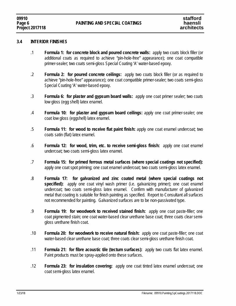
09910 stafford Page 6 PAINTING AND SPECIAL COATINGS haensli Project 2017118 architects
1/23/18 Filename: 09910.Painting.SpCoatings.2017118.DOC
3.4 INTERIOR FINISHES .1 Formula 1: for concrete block and poured concrete walls: apply two coats block filler (or
additional coats as required to achieve “pin-hole-free” appearance); one coat compatible primer-sealer; two coats semi-gloss Special Coating ‘A’ water-based epoxy.
.2 Formula 2: for poured concrete ceilings: apply two coats block filler (or as required to
achieve “pin-hole-free” appearance); one coat compatible primer-sealer; two coats semi-gloss Special Coating ‘A’ water-based epoxy.
.3 Formula 6: for plaster and gypsum board walls: apply one coat primer sealer; two coats
low gloss (egg shell) latex enamel. .4 Formula 10: for plaster and gypsum board ceilings: apply one coat primer-sealer; one
coat low gloss (eggshell) latex enamel. .5 Formula 11: for wood to receive flat paint finish: apply one coat enamel undercoat; two
coats satin (flat) latex enamel. .6 Formula 12: for wood, trim, etc. to receive semi-gloss finish: apply one coat enamel
undercoat; two coats semi-gloss latex enamel. .7 Formula 15: for primed ferrous metal surfaces (where special coatings not specified):
apply one coat spot priming; one coat enamel undercoat; two coats semi-gloss latex enamel. .8 Formula 17: for galvanized and zinc coated metal (where special coatings not
specified): apply one coat vinyl wash primer (i.e. galvanizing primer); one coat enamel undercoat; two coats semi-gloss latex enamel. Confirm with manufacturer of galvanized metal that coating is suitable for finish painting as specified. Report to Consultant all surfaces not recommended for painting. Galvanized surfaces are to be non-passivated type.
.9 Formula 19: for woodwork to received stained finish: apply one coat paste-filler; one
coat pigmented stain; one coat water-based clear urethane base coat; three coats clear semi-gloss urethane finish coat.
.10 Formula 20: for woodwork to receive natural finish: apply one coat paste-filler; one coat
water-based clear urethane base coat; three coats clear semi-gloss urethane finish coat. .11 Formula 21: for fibre acoustic tile (tectum surfaces): apply two coats flat latex enamel.
Paint products must be spray-applied onto these surfaces. .12 Formula 23: for insulation covering: apply one coat tinted latex enamel undercoat; one
coat semi-gloss latex enamel.
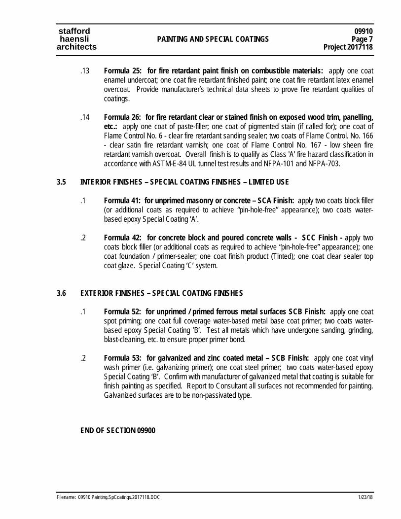
stafford 09910 haensli PAINTING AND SPECIAL COATINGS Page 7 architects Project 2017118
Filename: 09910.Painting.SpCoatings.2017118.DOC 1/23/18
.13 Formula 25: for fire retardant paint finish on combustible materials: apply one coat enamel undercoat; one coat fire retardant finished paint; one coat fire retardant latex enamel overcoat. Provide manufacturer’s technical data sheets to prove fire retardant qualities of coatings.
.14 Formula 26: for fire retardant clear or stained finish on exposed wood trim, panelling,
etc.: apply one coat of paste-filler; one coat of pigmented stain (if called for); one coat of Flame Control No. 6 - clear fire retardant sanding sealer; two coats of Flame Control. No. 166 - clear satin fire retardant varnish; one coat of Flame Control No. 167 - low sheen fire retardant varnish overcoat. Overall finish is to qualify as Class 'A' fire hazard classification in accordance with ASTM-E-84 UL tunnel test results and NFPA-101 and NFPA-703.
3.5 INTERIOR FINISHES – SPECIAL COATING FINISHES – LIMITED USE .1 Formula 41: for unprimed masonry or concrete – SCA Finish: apply two coats block filler
(or additional coats as required to achieve “pin-hole-free” appearance); two coats water-based epoxy Special Coating ‘A’.
.2 Formula 42: for concrete block and poured concrete walls - SCC Finish - apply two
coats block filler (or additional coats as required to achieve “pin-hole-free” appearance); one coat foundation / primer-sealer; one coat finish product (Tinted); one coat clear sealer top coat glaze. Special Coating ‘C’ system.
3.6 EXTERIOR FINISHES – SPECIAL COATING FINISHES .1 Formula 52: for unprimed / primed ferrous metal surfaces SCB Finish: apply one coat
spot priming; one coat full coverage water-based metal base coat primer; two coats water-based epoxy Special Coating ‘B’. Test all metals which have undergone sanding, grinding, blast-cleaning, etc. to ensure proper primer bond.
.2 Formula 53: for galvanized and zinc coated metal – SCB Finish: apply one coat vinyl
wash primer (i.e. galvanizing primer); one coat steel primer; two coats water-based epoxy Special Coating ‘B’. Confirm with manufacturer of galvanized metal that coating is suitable for finish painting as specified. Report to Consultant all surfaces not recommended for painting. Galvanized surfaces are to be non-passivated type.
END OF SECTION 09900

09910 stafford Page 8 PAINTING AND SPECIAL COATINGS haensli Project 2017118 architects
1/23/18 Filename: 09910.Painting.SpCoatings.2017118.DOC
This Page Intentionally Left Blank
Mechanical Specifications for
2017 ALTERATIONS TO EXISTING PLANT / BUILDING FOR NEW PRESS / LAMINATOR FOR:
SONOCO PRODUCTS COMPANY FLEXIBLE DIVISION Project No. 2017118 - 2
JSC Project No. 17-283-2
Issued for Tender
Date: January 23, 2018 Prepared by: Jain Sustainability Consultants Inc. 7405 East Danbro Crescent, 2nd Floor Mississauga, ON, L5N 6P8
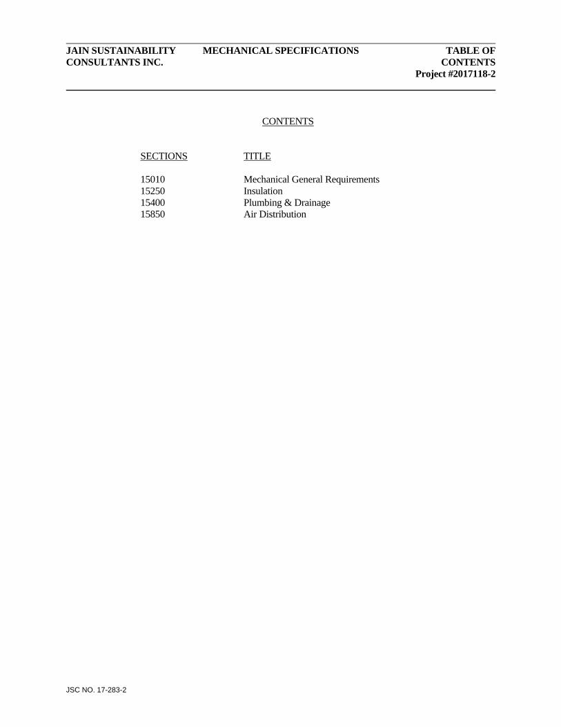
JAIN SUSTAINABILITY MECHANICAL SPECIFICATIONS TABLE OF CONSULTANTS INC. CONTENTS Project #2017118-2
JSC NO. 17-283-2
CONTENTS
SECTIONS TITLE 15010 Mechanical General Requirements 15250 Insulation 15400 Plumbing & Drainage 15850 Air Distribution
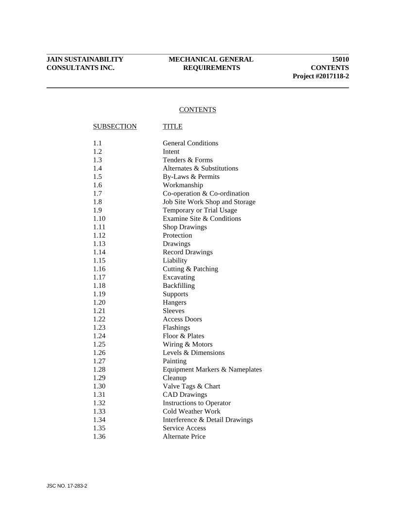
JAIN SUSTAINABILITY MECHANICAL GENERAL 15010 CONSULTANTS INC. REQUIREMENTS CONTENTS Project #2017118-2
JSC NO. 17-283-2
CONTENTS SUBSECTION TITLE 1.1 General Conditions 1.2 Intent 1.3 Tenders & Forms 1.4 Alternates & Substitutions 1.5 By-Laws & Permits 1.6 Workmanship 1.7 Co-operation & Co-ordination 1.8 Job Site Work Shop and Storage 1.9 Temporary or Trial Usage 1.10 Examine Site & Conditions 1.11 Shop Drawings 1.12 Protection 1.13 Drawings 1.14 Record Drawings 1.15 Liability 1.16 Cutting & Patching 1.17 Excavating 1.18 Backfilling 1.19 Supports 1.20 Hangers 1.21 Sleeves 1.22 Access Doors 1.23 Flashings 1.24 Floor & Plates 1.25 Wiring & Motors 1.26 Levels & Dimensions 1.27 Painting 1.28 Equipment Markers & Nameplates 1.29 Cleanup 1.30 Valve Tags & Chart 1.31 CAD Drawings 1.32 Instructions to Operator 1.33 Cold Weather Work 1.34 Interference & Detail Drawings 1.35 Service Access 1.36 Alternate Price

JAIN SUSTAINABILITY MECHANICAL GENERAL 15010 CONSULTANTS INC. REQUIREMENTS Page 1 Project #2017118-2
JSC NO. 17-283-2
1.1 GENERAL .1 Conform to Division 1, General Requirements .2 Unless specified otherwise, this Section shall apply to all Sections of Division 15. 1.2 INTENT .1 Mention herein or indication on Drawings of articles, materials, operations or methods
requires: supply of each item mentioned or indicated, of quality, or subject to qualifications noted; installation according to conditions stated: and, performance of each operation prescribed with furnishing of necessary labour, equipment, and incidentals for mechanical work, Division #15 and all Sections.
.2 Where used, words "Section" and "Division" shall also include other Subcontractors
engaged on site to perform work to make building and site complete in all respects. .3 Where used, word "supply" shall mean furnishing to site in location required or directed
complete with accessory parts. .4 Where used, word "install" shall mean secured in place and connected up for operation as
noted or directed. .5 Where used, word "provide" shall mean supply and install as each is described above. .6 Where used, wordings such as "approved, to approval, as directed, permitted, permission,
accepted, acceptance, report to", shall mean "approved, directed, permitted, accepted, report to", by Architect.
1.3 TENDERS & FORMS .1 Submit tender based on specified described equipment or Alternates listed. See attached
Supplementary Tender Form. .2 State in Tender, names of all Subcontractors proposed for work under this Division.
Division 15 work includes but is not limited to work described in Sections 15010, 15250, 15300, 15400, and 15850.
1.4 ALTERNATES & SUBSTITUTIONS .1 Throughout Division 15 are lists of "Alternate Equipment" manufacturers acceptable to
Architect if their product meets characteristics of specified described equipment.
15010 MECHANICAL GENERAL JAIN SUSTAINABILITY Page 2 REQUIREMENTS CONSULTANTS INC. Project #2017118-2
JSC NO. 17-283-2
.2 Each Bidder may elect to use "Alternate Equipment" from lists of Alternates where listed. These must be listed in Supplementary Tender Form. No substitutions after contract signing.
.3 It is the responsibility of this Division to ensure "Alternate Equipment" fits space allotted
and gives performance specified. If an "Alternate Equipment" unit is proposed and does not fit space allotted nor equal specified product in Architect's opinion, supply of specified described equipment will be required without change in Contract amount. Only manufacturers listed will be accepted for their product listing. All other manufacturers shall be quoted as substitution stating conditions and credit amount stating conditions and credit amount.
.4 If item of material specified is unobtainable, state in Tender proposed substitute (only
from approved alternate list) and amount added or deducted for its use. Extra monies will not be paid for substitutions after Contract has been awarded.
.5 If pipe or item, of size or weight indicated, is unobtainable, supply next larger size or
heavier weight without additional charge. 1.5 BY-LAWS & PERMITS .1 Obey Government, Municipal and Underwriters Standards and perform work in
accordance with requirements of By-Laws and Regulations in force where building is located.
.2 Apply for, obtain, and pay for permits and inspections required by authorities having
jurisdiction. Furnish necessary certificates as evidence that work installed conforms with laws and regulations of authorities having jurisdiction. Make minor changes required by By-Laws and Regulations of authorities having jurisdiction without extra payment.
1.6 WORKMANSHIP .1 Workmanship and method of installation shall conform to best standards and practice and
be performed to approval. Work shall be done by tradesmen skilled in work to be performed. Where required by local or other By-Laws and Regulations, tradesmen shall be licensed in their trade. Install all work and equipment to manufacturer's printed directions.
.2 The Mechanical Contractor shall have a qualified Superintendent on site to overview and
supervise the work and to coordinate his work with other Trades. The Superintendent shall also coordinate the work between Mechanical Subtrades.

JAIN SUSTAINABILITY MECHANICAL GENERAL 15010 CONSULTANTS INC. REQUIREMENTS Page 3 Project #2017118-2
JSC NO. 17-283-2
1.7 CO-OPERATION & CO-ORDINATION .1 Each Section and Trade shall:
.1 Confer with other Sections and arrange work so it will be carried on in best interests of all concerned bearing in mind building construction and finish required.
.2 Furnish "built-in" items in ample time and give necessary information and assistance in connection with building-in of same. Notify Section concerned in writing of size and location of recesses, openings and chases at least 48 hours before walls are erected, floors poured and similar work.
.3 Proceed as quickly as practical so that construction may be completed in shortest possible time.
1.8 JOBSITE WORK SHOP AND STORAGE .1 Supply job site office, workshop, tools, scaffolds and material storage as required to
complete the work of this Division. Location of temporary buildings, use of space on site or within building shall be to later direction.
1.9 TEMPORARY OR TRIAL USAGE .1 Temporary or trial usage of any mechanical device, machinery, apparatus, equipment or
materials shall not be construed as evidence of acceptance of same and no claim for damage shall be made for injury to or breaking of any part of such work which may be so used.
1.10 EXAMINE SITE & CONDITIONS .1 Examine site and local conditions. Examine carefully all Drawings and complete
Specifications to ensure that work and equipment will satisfy conditions and performance requirements as shown. Before commencing work, examine the work of other Sections and report at once any defect or interference affecting the work, its completion or warranty. No allowance will be made later for any expense incurred through failure to make these examinations or to report any such discrepancies in writing.
1.11 SHOP DRAWINGS .1 Submit for review within 14 days of Contract award, 8 copies of Shop Drawings and
Room Equipment Schedules covering material to be supplied. .2 Each Shop Drawing must be certified correct by submitting trade before submission.
Shop Drawings not so certified will be rejected.
15010 MECHANICAL GENERAL JAIN SUSTAINABILITY Page 4 REQUIREMENTS CONSULTANTS INC. Project #2017118-2
JSC NO. 17-283-2
.3 Submit Shop Drawing for review for accordance with Section 01001. Make printed submissions of more than two pages in booklet form. Failure to conform may cause undue delay in approvals.
.4 Review of Shop Drawings is for sole purpose of ascertaining conformance with general
design concept. This review shall not mean that Engineer approves detail design inherent in Shop Drawings, responsibility for which shall remain with Contractor and such review shall not relieve Contractor of his responsibility for errors or omissions in the shop drawings or of his responsibility for meeting all requirements of Contract Documents. Contractor is responsible for dimensions to be confirmed and correlated at site, for information that pertains solely to fabrication processes or to techniques of construction and installation and for co-ordination of work of all trades.
1.12 PROTECTION .1 Protect work from damage. Securely plug or cap open ends of conduits, pipes, ducts or
equipment to prevent entry of dirt, dust, debris, water, snow or ice. Clean all piping, ducting, conduits and equipment inside and outside before testing.
.2 Material stored on site shall be protected from weather and kept dry and clean at all
times. Take care to avoid corrosion of metal parts. Protect all bearings and motors from damage due to moisture and dust. Equipment not yet in operation shall be turned over at least at monthly intervals to prevent bearing deterioration.
.3 Supply and install on all corners and edges of equipment, ductwork piping, hangers and
obstructions mounted less than 2 m above floor in mechanical type rooms, suitable foam rubber edge guards to protect persons from injury.
1.13 DRAWINGS .1 Mechanical Drawings do not show structural and related details. Take information
involving accurate measurement of building from building drawings, or at building. Make, without additional charge, any necessary changes or additions to runs of piping, conduits and ducts to accommodate structural conditions. Location of pipes, ducts, conduits and other equipment may be altered by Architect without extra charge provided change is made before installation and does not necessitate major additional material. Do not scale drawings.
.2 As work progresses and before installing heating units, registers, diffusers, fixtures and
other fittings and equipment which may interfere with interior treatment and use of building, obtain detail drawings or directions for exact location of such equipment and fitments.
JAIN SUSTAINABILITY MECHANICAL GENERAL 15010 CONSULTANTS INC. REQUIREMENTS Page 5 Project #2017118-2
JSC NO. 17-283-2
.3 Mechanical Drawings indicate general location and route of pipes, ducts and conduits which are to be installed. Where required work is not shown or only shown diagrammatically, install same to conserve head room (minimum 2200 mm clear in Service Areas and to achieve scheduled ceiling height in finished rooms.) and interfere as little as possible with free use of space through which they pass. Conceal piping, conduits and ducts in furred spaces, ceilings and walls unless specifically shown otherwise. Install work close to structure so furring will be small as practical. Maintain 600 mm service space around serviceable units.
.4 Install piping and ductwork to clear structural members and any fireproofing. Locate
mechanical work to permit installation of specified insulation. Do not remove or damage structural fireproofing. Leave space to permit fireproofing and insulation to be inspected and repaired. Suspended suits shall not be obstructed from easy removal by interferring pipes, ducts, conduits or any other obstruction below the units.
.5 Before commencing work, check and verify all sizes, locations, grade and invert
elevations, levels and dimensions to ensure proper and correct installation. Verify exterior municipal services.
.6 Locate all mechanical and electrical equipment in such a manner as to facilitate easy and
safe access to and maintenance and replacement of any part. .7 In every place where there is indicated space reserved for future or other equipment,
leave such space clear, and install piping and other work so that necessary installation and connections can be made for any such apparatus. Obtain instructions whenever necessary for this purpose.
.8 Relocate equipment and/or material installed but not co-ordinated with work of other
Sections as directed, without extra charge. 1.14 RECORD DRAWINGS
.1 Conform to General Requirements. Maintain at least 2 sets of documents and clearly mark on same as job progresses, changes and deviations from work shown so that on completion Owner will have records of exact location of ducts and equipment and record of material and equipment changes.
.2 Contractor shall obtain clean set of prints from Consultant at start of Contract Work and
shall keep these prints up-to-date at jobsite, accurately recording all changes made on project and locating all services, equipment, etc. which may have been shown only diagrammatically on Contract Documents.

15010 MECHANICAL GENERAL JAIN SUSTAINABILITY Page 6 REQUIREMENTS CONSULTANTS INC. Project #2017118-2
JSC NO. 17-283-2
.3 Contractor shall ensure that as-built information is accurately recorded and shall check same. As-Built drawings shall be reviewed with Consultant at each jobsite meeting.
.4 Upon completion of Contract Work, prior to Substantial Performance inspection and after final review with Consultants, Contractor shall neatly transfer recorded information and make final As-Built submission to Consultant for review in the following form: - One (1) set of clean, legible prints. - One (1) ACAD 2017 format drawings. Files shall retain all setting (layers, line
types, scales colors, etc) as used in the drawing files (produced) by consultant.
.5 After Record Drawings have been reviewed, revised if necessary until acceptable to the consultant. Deliver drawings in the form of CD (CAD + PDF) and three (3) sets of prints taken from that CD to Owner.
1.15 LIABILITY .1 Each Section and Trade shall:
.1 Assume full responsibility for laying out his work and for any damage caused to other Sections or Owner by improper location or carrying out of same.
.2 Be responsible for prompt installation of work in advance of concrete pouring, ceiling installation or similar work.
.3 Protect finished and unfinished work of this Division and work of other Sections from damage due to work of this Division.
.4 Be responsible for condition of material and equipment supplied. Be responsible for protection and maintenance of work completed until termination and acceptance.
1.16 CUTTING & PATCHING .1 Perform all cutting and patching required for work of this Division under the supervision
of the General Contractor. Lay out and install work in advance of other Sections. Bear all costs resulting from failing to comply with this requirement. Cutting and patching shall be performed by skilled experience personnel specializing in applicable materials or finishes.
.2 Core drill holes in concrete walls and floors for piping where not previously sleeved. Do
not use mechanical hammers or drills without prior approval in writing. Neatly patch holes to approval and where located in exterior walls above grade, make watertight. Make holes in walls below grade with due provision for pipe movement (min. 50 mm clear all around), fill with 50 mm thick fibreglass blanket insulation and seal watertight with mastic.
JAIN SUSTAINABILITY MECHANICAL GENERAL 15010 CONSULTANTS INC. REQUIREMENTS Page 7 Project #2017118-2
JSC NO. 17-283-2
.3 Lay out cutting and patching for approval before starting and obtain approval of finished work.
.4 See 1.19 Supports, 1.20 Hangers and 1.21 Sleeves, and co-ordinate this work to other
Sections to prevent unnecessary cutting & patching. 1.17 EXCAVATING .1 Perform necessary excavating for work of this Division. Ensure bottoms of trenches are
excavated so that full length of each pipe will be supported on solid bed of undisturbed earth. Build approved concrete pad, solid block or concrete piers properly reinforced under piping below grade where solid undisturbed earth bed is not obtainable to meet Plumbing Code.
.2 Remove excavated materials not used as backfill from site unless otherwise directed. .3 See Soil Test Report re existing soil conditions. Support all piping on approved earth or
other foundation or hangers. Earth support must be minimum 90% density Modified Proctor (ASTM #D-1527) compaction and proven such conditions exist. Include for necessary soil tests to verify earth foundation will support drains as required at approximately 2400 mm centres. Provide supports to meeting Plumbing Code, Section 51 including piers where earth foundation or hangers are not acceptable to Architect or authority having jurisdiction.
.4 Where permitted by authority having jurisdiction where pipe invert is less than 900 mm
below floor elevation steel clevis hangers, steel rods and continuous steel supports from floors at half normal spacing may be used. Paint all buried metal hanger work with 2 coats of Bakelite #110-14. See 15010-1.20.
.5 Provide necessary shoring and support for trenching. Do all work in conformity to
Ontario Trench Excavator's Protection Act and Occupational Health & Safety Act, each as amended to date. Trench widths shall be kept to minimum dimension as directed & approved.
.6 Perform necessary pumping to maintain excavations free of water for work of this
Division until backfill is completed. .7 Provide 100 mm bed of 20 mm crusher run limestone compacted to 98% Modified
Proctor under all piping not laid in sandy ground or other approved bedding. For copper and plastic piping, bedding shall be clean sand.
15010 MECHANICAL GENERAL JAIN SUSTAINABILITY Page 8 REQUIREMENTS CONSULTANTS INC. Project #2017118-2
JSC NO. 17-283-2
1.18 BACKFILLING .1 Backfill at least first 150 mm above top of piping with clean coarse sand hand placed in
75 mm layers and compacted to 98% density Proctor Modified (ASTM #D1527). Note conditions and Details and conform thereto.
.2 Backfill inside building with M.T.C. granular 'B' or clean coarse sand in 150 mm layers
mechanically compacted to give minimum of 98% density Modified Proctor (ASTM #D-1527 STD) compaction.
.3 For Landscape Areas: Backfill outside building with approved clean earth in 300 mm
layers watered and compacted to 98% Modified Proctor. Do not use clay, rock, frozen earth, rubbish or other unapproved materials. Remove same from site and bring in approved earth or sand for use in this event.
.4 Backfill under all existing, new and future concreted, paved or gravelled areas with
M.T.C granular 'B' placed in 150 mm layers and compacted to 98% Modified Proctor Compaction to level of sub-base of paving or gravel.
.5 Other Sections will provide exterior finish work such as sod, trees, walks and paving.
Co-operate with these Sections to complete exterior mechanical work as soon as practical leaving surfaces in approved condition so other work may proceed.
.6 Compaction rates noted shall be maximum dry density value. .7 Where excavating is necessary close to and parallel with and below any footing bearing
backfill with concrete to top of highest adjacent footing with concrete of strength designated by Architect who will determine when condition exists.
.8 Where piping or drains pass below footings, sleeve same to give minimum of 50 mm
clear all-around and backfill with concrete of same strength as footing up to underside of footing.
1.19 SUPPORTS .1 Provide supports, stands and platforms necessary for proper installation of equipment and
components, of concrete, steel or wood as may be required and as approved or elsewhere shown or specified. Provide necessary anchor bolts and other fastenings. Secure work to concrete with Phillips "Red Head" concrete anchors.
JAIN SUSTAINABILITY MECHANICAL GENERAL 15010 CONSULTANTS INC. REQUIREMENTS Page 9 Project #2017118-2
JSC NO. 17-283-2
.2 Construct concrete bases and floating slabs at least 100 mm high (or as otherwise noted), of 30 MPa concrete with trowel finish in compliance with applicable articles of Concrete Section for support of equipment noted, size 50 mm larger than base of apparatus with outside corners chamfered 40 mm. Grout pumps and equipment to their bases to approval.
1.20 HANGERS .1 Provide hangers to support unburied piping and ducts. Adjust hangers so that piping will
be true in respect of alignment and grade. Obtain approval of methods of hanging to building before proceeding. Ensure that load on building structure does not exceed maximum mechanical loading per square metre shown on Structural Drawings or as directed by Architect. Take special care to avoid introduction of undue reaction forces into structure of building, to flanges of pumps and equipment, to expansion joints and to piping.
.2 Do not hang from steel or tectum decking. Provide structural framing where necessary to
support work in these areas. Do not use ceiling suspension system for support of ducts, grilles, pipes, etc.
.3 Support unburied horizontal cast iron piping at each hub length (max. 1500 mm) with
Grinnell #260 or Myatt #124 clevis hangers. Where groups of fittings occur, not more than 900 mm shall be between hangers.
.4 Support other horizontal piping with Grinnell #260 or Myatt #124 clevis hangers as
follows: Up to 32 mm size - 1800 mm maximum spacing 38 to 75 mm size - 3000 mm maximum spacing 88 mm and larger - 4300 mm maximum spacing .5 Support plumbing piping in accordance with more stringent requirements of Plumbing
Code or otherwise specified. .6 Where hangers are grouped, locate spacing by smallest size pipe. Do not use trapeze type
hangers unless specifically shown. Where trapeze hangers are used, fit insulated piping with Grinnell #167 or Myatt #251 insulation shields taped to insulation.
.7 Support through vertical piping with Grinnell #261 or Myatt #182 riser clamps at each
floor level or maximum of 3000 mm whichever is shorter. Secure vertical RWL, soil and vent risers at 1500 mm intervals to approval. Secure small vertical piping with long ring stays.
15010 MECHANICAL GENERAL JAIN SUSTAINABILITY Page 10 REQUIREMENTS CONSULTANTS INC. Project #2017118-2
JSC NO. 17-283-2
.8 On copper piping, provide approved separation to ensure no contact between copper and ferrous hanger or other work. Provide barrier to prevent copper pipe being in contact with ferrous or cinder materials.
.9 Support hangers with threaded mild steel hanger rods sized in accordance with hanger
manufacturer's tables. Affix to building structure by coach screw threads into wood construction, by Grinnell #281 or equal inserts into concrete, by beam clamps on to structural steel work, or by bolts or welding. Where inserts are incorrectly placed, Phillips "Red Head" concrete anchors may be used. Secure hanger rods to top chord of steel joists at joist panel points only.
.10 Piping 150 mm size and larger must be supported by cast-in place inserts unless
otherwise noted. .11 Support piping on walls with Myatt #157 offset wall hooks fastened to wall with toggle
bolts or Phillips "Red Head" concrete anchors. .12 Where structural bearings do not exist, provide angle or channel iron of sufficient size
from other structural bearings to support hangers or equipment. .13 Do not use wire, chain, strap or extension bar hangers under any circumstance. .14 Hangers shall be arranged so as to load structural steel in a concentric manner. Loads to
be imparted either on joist panel points or within 150 mm of panel joint. .15 Do NOT use percussion type fastenings of any kind without prior approval in writing. .16 Install all piping supported from hangers or supports in a manner to ensure that building
construction is not weakened or over-stressed, that pipes are secure, vibration free, free to expand and contract and properly graded, and that vertical adjustment of horizontal piping is possible after erection.
.17 Support all hangers directly from building structure only. Do not support pipes, ducts or
other equipment from other pipes, ducts, equipment, suspended ceilings or their suspension systems.
.18 Hang piping for at least 2 support points from isolated equipment with Burgess-Vibro
Acoustics or equal "SH" isolators with steel spring having 25 mm minimum static deflection and series connected elastomer element having static deflection of 6 mm underload.
JAIN SUSTAINABILITY MECHANICAL GENERAL 15010 CONSULTANTS INC. REQUIREMENTS Page 11 Project #2017118-2
JSC NO. 17-283-2
1.21 SLEEVES .1 Where pipes pass through interior masonry walls, provide metallic pipe sleeves of
equivalent weight and material. Where ducts pass through interior masonry walls, provide suitable 18 gauge galvanized steel sleeves. Size sleeves on insulated piping or ducts to permit insulation to continue through sleeves.
.2 Where piping or ducts pass through interior concrete or frame construction, provide 1.2
mm thick galvanized iron sleeves. On copper pipe, provide copper pipe sleeves. .3 Sleeves on buried piping shall be 50 mm larger all round than pipe and be filled with 50
mm thick fiberglass blanket insulation and sealed with mastic. .4 Seal spaces between unburied pipes and ducts through "required fire separations" with
U.L.C. listed (Guide 40U19) fire stopping including pipe insulation. Fire stopping shall comply with O.B.C., be approved by local Building Department and installed as per listing Card. Fire stopping shall have approved FH (hose stream) rating.
.5 Seal all holes and openings through floors water tight. .6 In rooms with mechanical equipment or waterproofed floors with concrete topping,
sleeves through floors shall be welded water stop flange steel pipe sleeves poured in place and extending at least 100 mm above finished floor or pipes shall have Corrosion Services Co. Ltd. "Link Seals" installed to manufacturers directions. Where ducts pass through floors, another Section will provide 100 mm high by 100 mm concrete curb around ducts poured integrally with floor. Locate openings in field to be snug around ducts and be responsible for correct size and location.
1.22 ACCESS DOORS .1 Supply as required, 2.8 mm thick hinged metal access doors with frames for installation
by other Sections in walls or ceilings to permit access to built-in or unaccessible controls, dampers, valves, cleanouts and components. Where lift-out acoustic board ceilings are used, access doors are not required but boards shall be secured with accessible hold-down clips and marked with Bildemup #6RH brass paper fasteners inserted through boards and bent over. Paint heads with red enamel before installation.
.2 Access doors shall be Stelpro Ltd. #722 flush type of size to suit controls, valves,
cleanouts, dampers or components serviced, minimum size 300 mm x 300 mm "Reach-in", 300 x 600 mm "Crawl-in", with prime coat finish, concealed hinges, screwdriver lock and plaster key. Access doors in finished masonry or drywall construction shall be #722 less plaster key. Access doors shall be #704 in drywall ceilings. In tiled areas and wet areas, provide stainless steel access doors.
15010 MECHANICAL GENERAL JAIN SUSTAINABILITY Page 12 REQUIREMENTS CONSULTANTS INC. Project #2017118-2
JSC NO. 17-283-2
.3 Access doors in fire rated ceiling assemblies, all fire rated walls, duct shafts or in corridor walls shall be UL, ULC or WHI listed 1-1/2 hour fire rated access doors equal to LeHage #L1010, Nailor Hart #0900 or Acudor #150B with screwdriver lock.
.4 Access doors are to be provided (in ceilings or walls) adjacent to filter location of all heat
pumps for cleaning of coils. Provide access doors in bottom of return duct at each heat pump for access to and cleaning coil, and also cleaning of Kitchen and exhaust duct at each floor and at each change of direction.
.5 Alternate Equipment:
1. Smille, McAdams & Summerline Ltd. 2. Mifab (Modular Equipment Mfg. Inc.) 3. Can-Aqua Inc. 4. Acudor Products Ltd. 5. LeHage (Ancon Industries Ltd.) 6. Nailor Hart Industries Inc.
1.23 FLASHINGS .1 Where vents, stacks or other pipes pass through roof, provide Thaler insulated "Stack
Jacks", spun aluminum flashings and telescopic cap. .2 Where ducts pass through roof, another Section will provide suitable curb and flashing.
Provide approved counterflashing of same material as flashing. .3 Where equipment is roof mounted, provide suitable approved curbs (minimum 450 mm
high) and bases curbs and bases shall be flashed and sealed to roof by another division unless otherwise noted.
1.24 FLOOR & PLATES .1 Provide one piece nickel plated flanges of stamped brass in finished areas at points where
exposed uncovered pipe pass through walls, floor or ceilings. Secure plates at ceiling with integral brass set screw.
.2 Split plates will not be accepted.

JAIN SUSTAINABILITY MECHANICAL GENERAL 15010 CONSULTANTS INC. REQUIREMENTS Page 13 Project #2017118-2
JSC NO. 17-283-2
1.25 WIRING & MOTORS .1 Electric connections and wiring for equipment supplied under this Division will be by
Electrical Division except for Temperature Control System, Mechanical Firing Equipment and other equipment noted elsewhere. See Starter Schedule. Provide electric wiring to complete all systems. All electrical work must conform to conditions noted in Electrical Division and be concealed except in service areas. All wiring MUST be in conduit or EMT using #18 wire for 24 volt or less, #14 wire for 120 volt control and #12 wire for 120 volt power wiring.
.2 Electrically operated equipment shall be C.S.A. approved and bear approval label.
Special Inspection Label of Provincial Authority having jurisdiction will be accepted in lieu of C.S.A. approval. Each motor shall have an approved starter.
.3 Prime plumbing, heating, ventilating and air conditioning starter equipment shall be
fitted so that these unit will automatically restart on resumption of power after power outage.
.4 Provide motor starters, controls and accessories required to operate equipment installed.
Supply necessary wiring diagrams and instructions to Electrical Division. Starters and controls shall be for surface or flush mounting as required. Arrange equipment, piping and ductwork to permit access to and mounting of starters and controls. Co-operate with Electrical Division to ensure electrical equipment can be installed and serviced. See Electrical Drawings.
.5 Electrically operated equipment, starters and controls shall be rated for satisfactory
operation on following nominal system voltages unless otherwise noted: Up to and including 250 W - 60/1/120 V 370 W and larger - 208/3 or 575/3 as noted. SEE STARTER SCHEDULE .6 Magnetic starters shall be combination type with disconnect feature unless starter is built
into unit control panel. Similar magnetic contactors shall be used for non-motor applications. All starters operated by PLC to have A/O/H.
.7 Supply pilot light, necessary fuses and overload heater coils for each starter. Fit each
single phase starter with neon lamp pilot light and three phase starters with transformer type incandescent with amber lens cap. Fit each three phase starter with at least two auxiliary contacts. Fit each three phase starter with three overload heaters. Size overload heaters at maximum 115% of actual unit name plate rating.
15010 MECHANICAL GENERAL JAIN SUSTAINABILITY Page 14 REQUIREMENTS CONSULTANTS INC. Project #2017118-2
JSC NO. 17-283-2
.8 Where equipment is noted to be electrically interlocked, supply necessary interlocks via double voltage relays (Mylar shroud accepted) to ensure specified operation. Magnetic starters shall be fused except where power is taken from separate protected circuit or is otherwise protected. Electrical interlocks and control devices shall operate on 120 volts A.C. maximum. Provide necessary fused and grounded control transformers to suit.
.9 Unless otherwise noted motors shall be dripproof, shielded ball bearing, EEMAC
Specification MG1, Design B, 1.15 service factor, Class 130 insulation, of Canadian manufacture with local service available, be rated for satisfactory operation on noted nominal system voltages and bear proper nameplate. Electric motor operated equipment shall have motor sized to bring unit to full operating RPM in ten seconds unless unit is equipped with integral thermal device to prevent motor burnout. Motors shall be 1800 RPM unless otherwise noted.
.10 Motors 14.9 KW and larger or where shown on schedules shall be equipped with integral
thermal protective devices per CSA #22.2, #77-1970 (PTC thermistor or approved equal) installed in each section of stator winding complete with automatic reset relay. Wiring by Electrical Division.
.11 For motors 14.9 KW and larger, supply field mounted Cutler Hammer or equal "Soft
Start" solid state motor controller with reduced voltage starting, motor overvoltage protection and energy saving feature. Field adjust each controller to give proper efficient performances.
.12 Starters shall be General Electric Co. or Alternate. All exposed mounted starters shall be
of ONE manufacture. Fit fuse gaps in fusible equipment with complete set of proper size Gould Shawmut blade type, time delay current limiting fuses (HRC1-J). Ensure fusible equipment supplied will reject standard NEC fuses. Co-ordinate fuses for motors to give maximum protection, and of one manufacture throughout.
.13 Starters which are started automatically by remote pilot device (or interlock) such as
timer, E.M.S., level controller, pressure switch, thermostat or flow switch shall include "Hand-Off-Auto" (H.O.A.) selector switch. "Hand" position shall permit shunting of pilot device or interlock. Where such units also have protective pilot device (eg: firestat) such device shall be wired into both "Hand" and "Auto" position and shall not be shunted.
.14 Supply to Owner at least three fuses of each size suitably labelled. Obtain duplicate
receipt for same. Submit for review complete list of all starters showing make, size, accessories, labels and fusing.
JAIN SUSTAINABILITY MECHANICAL GENERAL 15010 CONSULTANTS INC. REQUIREMENTS Page 15 Project #2017118-2
JSC NO. 17-283-2
.15 Alternate Starters: (See Equipment Schedule) 1. Klockner Moeller Limited 2. Furnas Electric Canada Limited 3. Square 'D' Company of Canada Limited 4. Allen-Bradley Canada Limited 5. Cutler Hammer Industries Controls 1.26 LEVELS & DIMENSIONS .1 General Contractor, on request, will supply this Division with necessary levels and
dimensions which are required to relate work of this Division to other Sections. Maintain all lines and levels so given.
1.27 PAINTING .1 Supply all equipment and materials fabricated from iron or steel (except piping and
ductwork materials) prime painted at factory before shipment. If damaged, touch up with suitable primer and leave ready for painting. All auxiliary support steel supplied by this Division shall be prime painted with one coat of red oxide primer. If prefinished equipment are damaged, make good and touch-up to match original finish.
.2 All metal parts, miscellaneous metal items and work installed exterior to building must be
degreased and prime painted unless otherwise noted. Exterior metals shall be galvanized (hot dip) except Kitchen hood exhaust duct and prefinished items.
.3 Painting of bare piping, ductwork, insulation and finish painting of equipment will be
done by another Section unless otherwise noted. Leave all work in clean, paintable condition. This Section to paint gas piping yellow.
.4 Exposed piping will be painted in Owners standard colours. Co-operate with Painting
Section to identify piping to ensure colour code is followed. 1.28 EQUIPMENT MARKERS & NAMEPLATES .1 Attach to each item of equipment (including electric motors), proper manufacturer's
nameplate showing size, model number, serial number, and all information usually provided including voltage, cycle, phase and horsepower of motors and name and address of unit manufacturer.
.2 Ensure stamped, etched or engraved lettering on plates is legible. Nameplates shall not be
painted over and where apparatus is insulated, provide adequate openings in insulation for viewing purposes.

15010 MECHANICAL GENERAL JAIN SUSTAINABILITY Page 16 REQUIREMENTS CONSULTANTS INC. Project #2017118-2
JSC NO. 17-283-2
.3 Provide on each item of equipment, starters, timers and controls suitable nameplates, e.g. "Heating Boiler #1, Second Floor Toilet Exhaust Fan Timer". Before nameplates are made, submit sample and list of names for approval. Make nameplates of 1.6 mm thick weather resistant rigid laminated plastic with engraved letters on black background. Secure nameplates with drive screws. Make letters on starters, timers and small items at least 5 mm high and at least 10 mm high on larger units such as pumps, fans, boilers, A.C. & S.A. Units, H.P. Units and condenser. Generally, unit nameplates shall conform to those noted in their Schedules.
1.29 CLEANUP .1 On completion, remove from premises surplus materials and debris resulting from work
of this Division. Keep work areas clean and in a workmanlike manner at all times to approval.
.2 Fill in, compact and level off exterior excavations after final settlement of backfill to
approval. 1.30 VALVE TAGS & CHART .1 Provide on each valve, 25 mm diameter or larger brass tag with punched and embossed
numbers. Valves immediately adjacent to plumbing fixtures or radiation need not be tagged.
.2 Provide where later directed, a neat, glass fronted, framed chart showing number,
location, service and function of each valve and lines controlled. Mount 1800 mm above floor to bottom.
.3 Frame each pressure vessel, H.W. tank and Boiler Certificate under glass and hang where
directed in room where unit is located. Mount 1800 mm above floor to bottom. .4 Identify exposed service piping at 6 m intervals and at each valve behind access panel
with service name marked on piping using "Mystic" labels (H.A. Scarlett Industries), Westline or Brady "Perma-Code" labels, each applied with #3M clear adhesive. Replace loose or lost labels at end of one year guarantee period without charge. Painted stencil markings are acceptable. Provide direction of flow arrow at each Service label. Identification also required on duct runs with flow indication and also required for in-ceiling services that have access to them (ie. Lay-in ties).
.5 Provide for each heat pump, a stamped nameplate fixed to ceiling grid indicating location
of heat pump filters to facilitate servicing. Obtain Architect's permission before installing.

JAIN SUSTAINABILITY MECHANICAL GENERAL 15010 CONSULTANTS INC. REQUIREMENTS Page 17 Project #2017118-2
JSC NO. 17-283-2
1.31 CAD DRAWINGS .1 If required for coordination purposes or for As-Builts, the Contractor may obtain Design
Drawings from the Consultant after completing the required Document Request Form and paying a handling charge of $75 + HST per drawing.
1.32 INSTRUCTIONS TO OPERATOR .1 Instruct Building Operators in repair, maintenance and operation of Mechanical Systems
and associated equipment. Commission all equipment by starting up and running through all cycles.
.2 Contractor will be responsible for collecting and organizing three (3) copies of all data,
operating instructions, trouble-shooting instructions, parts list, parts diagrams, evidence of all tests, maintenance manuals, valve tags and directory, balancing reports, etc. and assembling them in neat manuals.
.3 Contractor shall also collect from Subtrades and Suppliers all Guarantees/Warranties
specified. Check that starting date (date of Substantial Performance of entire project) and extent of each guarantee/warranty are clearly indicated. Check also that all guarantees/warranties indicate Supplier’s Name or Subcontractor’s Name as appropriate together with contact phone number. Assemble neatly in labeled section of each manual.
.4 Submit copy of manuals to Consultant for approval prior to requesting of Substantial
Performance by Contractor and inspection for same. .5 Arrange for on-site instruction by various Equipment Manufacturers where considered
necessary by Consultant, at no additional cost to Owner. .6 Lack of submitting proper Maintenance Manuals/Instructions for equipment at time of
substantial performance will result in that this trade contractor will remain responsible for the maintenance until such time as information provided.
1.33 COLD WEATHER WORK .1 Wherever work is performed in surrounding air temperatures below 4.0oC special
approved precautions shall be taken to prevent damage to mortar, concrete or materials. All such materials used at such times shall be heated. Right is reserved to suspend work at any time should climatic conditions be deemed unsuitable for proper execution of work.
15010 MECHANICAL GENERAL JAIN SUSTAINABILITY Page 18 REQUIREMENTS CONSULTANTS INC. Project #2017118-2
JSC NO. 17-283-2
1.34 INTERFERENCE & DETAIL DRAWINGS .1 Prepare and submit for approval to architect through contractor, at least 6 copies of
Interference and Detail Drawings, minimum 1/50 scale, to co-ordinate work of this Division with all other Sections.
.2 Make Interference Drawings in conjunction with all parties and trades concerned
showing sleeves and openings and passage of piping and ductwork through building structure. Drawings shall also show inserts, special hangers and other features to indicate routing through confined spaces, installation of coils, silencers and other such items in such areas.
.3 Provide Detail Drawings, fully dimensioned, of piping, ducts and equipment in shafts,
Boiler and Mechanical Equipment, Service and Fan Rooms. Base equipment drawings on "Reviewed" Shop Drawings and include, but do not necessarily limit to, details pertaining to access, clearances, tappings, sleeves, electrical connections, drains and service spaces and integral control drawings.
.4 Provide Detail Drawings of sump pits, equipment bases, anchors, inertia slabs, floor and
roof curbs pertaining to this Division. 1.35 SERVICE ACCESS .1 All components of equipment must be easily accessible for service. Consult with
Engineer if drawings layout has to be modified to maintain service access shown on heat pumps details and floor plans. The same applies on equipment in mechanical rooms.
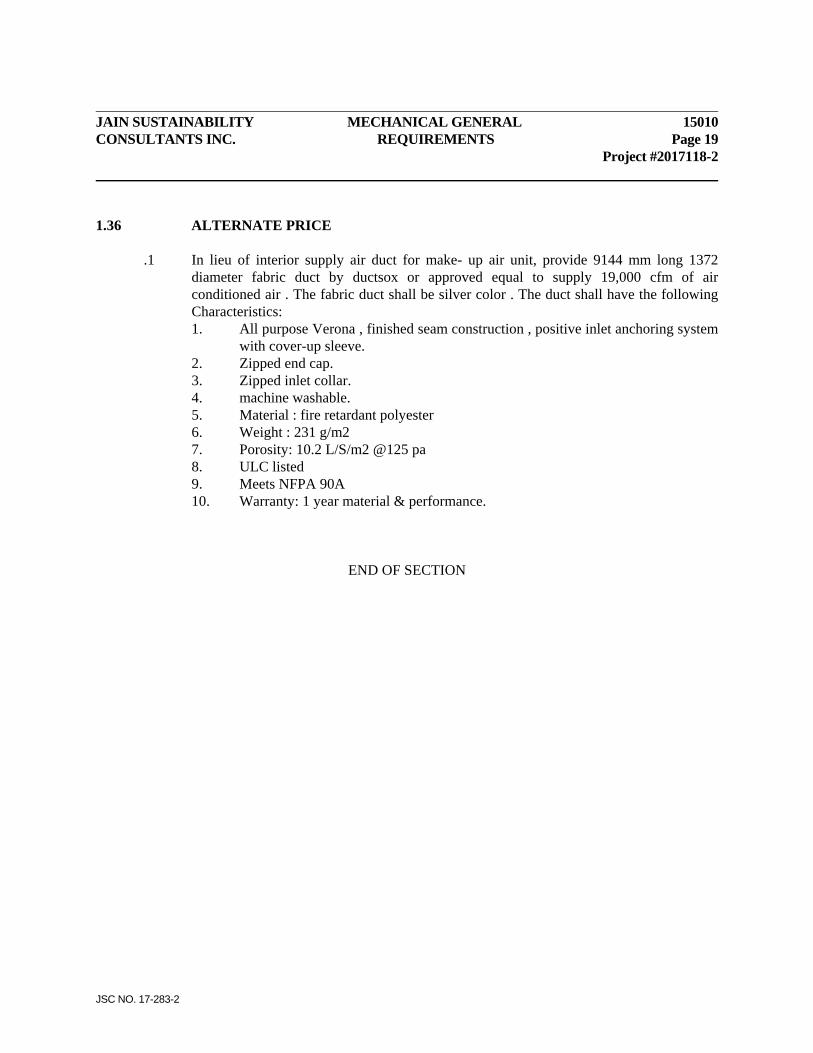
JAIN SUSTAINABILITY MECHANICAL GENERAL 15010 CONSULTANTS INC. REQUIREMENTS Page 19 Project #2017118-2
JSC NO. 17-283-2
1.36 ALTERNATE PRICE .1 In lieu of interior supply air duct for make- up air unit, provide 9144 mm long 1372
diameter fabric duct by ductsox or approved equal to supply 19,000 cfm of air conditioned air . The fabric duct shall be silver color . The duct shall have the following Characteristics: 1. All purpose Verona , finished seam construction , positive inlet anchoring system
with cover-up sleeve. 2. Zipped end cap. 3. Zipped inlet collar. 4. machine washable. 5. Material : fire retardant polyester 6. Weight : 231 g/m2 7. Porosity: 10.2 L/S/m2 @125 pa 8. ULC listed 9. Meets NFPA 90A 10. Warranty: 1 year material & performance.
END OF SECTION
JAIN SUSTAINABILITY INSULATION 15250 CONSULTANTS INC. CONTENTS Project #2017118-2
JSC NO. 17-283-2
CONTENTS SUBSECTION TITLE PART 1 - GENERAL 1.1 Related Instructions 1.2 Work Included 1.3 Submittals PART 2 - PRODUCTS 2.1 Materials 2.2 Piping & Equipment Insulation 2.3 Duct Insulation PART 3 - EXECUTION 3.1 Testing 3.2 Installation Instructions 3.3 Field Quality Control
JAIN SUSTAINABILITY INSULATION 15250 CONSULTANTS INC. Page 1 Project #2017118-2
JSC NO. 17-283-2
PART 1 - GENERAL 1.1 RELATED INSTRUCTIONS .1 Conform to Division 1, General Requirements. .2 Comply with requirements of Section 15010, Mechanical General Requirements. 1.2 WORK INCLUDED .1 Work under this contract shall include but is not limited to the following. .2 Supply and install insulation for following piping and duct systems:
.1 Domestic water piping. .2 Interior exhaust air ducts from backdraft dampers to louvres or outlets. .3 Miscellaneous piping and ducts noted on Drawings or in specifications. .4 Horizontal suspended sanitary soil and waste piping from W.C.'s, urinals and
drinking fountains. .5 Storm & sanitary drains as specified. .6 Water drain lines below handicapped lavatories. .7 Miscellaneous insulation as specified. .8 Supply and ducts.
1.3 SUBMITTALS .1 Submit detailed list of material for each service stating manufacture, 'K' value, density,
finish, flame spread and smoke ratings, permability, materials, finishes, cements and adhesives.
.2 Sample Board showing all product supplied, identified as to type and manufacture source. PART 2 - PRODUCTS 2.1 MATERIALS .1 Insulation, jackets and adhesives shall be incombustible and in compliance with Ontario
Building Code. Products containing asbestos shall not be used and confirm by certificate. .2 All insulation products used shall be fully tested and approved as fire retardent by
Underwriters Laboratories of Canada Limited. .3 Materials shall be of Canadian manufacture where available, of best quality of their
respective kinds and of uniform pattern throughout.
15250 INSULATION JAIN SUSTAINABILITY Page 2 CONSULTANTS INC. Project #2017118-2
JSC NO. 17-283-2
.4 All insulating materials shall be fire retardent. Adhesives shall be waterproof and incombustible flame resistant. Combustible wrappings or vapour barriers used in conjunction with thermal insulating materials shall be treated to reduce their combustibility so that flame spread classification of entire assembly shall not exceed 25 and smoke developed number shall not exceed 50. Submit report from an approved testing laboratory confirming foregoing ratings.
.5 Wheat pastes shall not be used. .6 Canvas covering shall be close weave fibre fire retarding canvas of weights specified,
135.6 g/m2 where concealed and at least 203.4 g/m2 where exposed to view. .7 Consultant reserves right to demand test samples to composite insulation systems for fire
hazard test rating. .8 Where wire is specified to secure insulation, it shall be stainless steel wire, 1.3 mm
gauge, dead soft annealed type. 2.2 PIPING & EQUIPMENT INSULATION .1 Unburied domestic cold water piping: 25 mm thick heavy density glass fibre preformed
pipe insulation with maximum of 0.033 conductivity at 10oC mean with factory applied vinyl foil kraft laminated glass fibre reinforced fire resistive vapour barrier jacket with not more than 1.15 perm rating (ASJ) with sealed lapped joints.
.2 Unburied domestic recirculation and hot water piping: heavy density glass fibre
preformed pipe insulation with maximum 0.043 conductivity at 93oC mean. Use 25 mm thickness on piping up to 50 mm size, and 38 mm thickness on piping 63 mm and above.
.3 On water and waste piping and trap below each Handicapped lavatory: insulate with 13
mm Armaflex II or Acwil "Therma-Cel" flexible foamed elastomeric insulation. Paint insulation with two coats of "White Finish".
.4 Unburied Rain Water Leaders and storm drains both exposed and concealed: insulate
with 25 mm thick fiberglass pipe covering with factory applied aluminum fire resistant vapour barrier and sealed lapped joints. Insulate underside of roof hoppers.
5 Exposed horizontal runs of sanitary drains: insulate as for storm drains above. Also
insulate horizontal wastes from urinals, toilets and drinking fountains concealed in ceiling spaces to vertical stack.
JAIN SUSTAINABILITY INSULATION 15250 CONSULTANTS INC. Page 3 Project #2017118-2
JSC NO. 17-283-2
.6 Exterior exposed piping: weatherproof insulation with two coats of Flintkote #C-29 applied over 45# building paper copper wired on and sealed to approval. Install insulation after electric trace wiring is tested and approved, if tracing is specified.
.7 Valves and fittings: 25 mm glass fibre blanket conforming to CGSB #51-BF11
compressed to same thickness as adjoining insulation and secured with jute twine. Over this apply smooth coat of insulating cement and recover with 4 oz. (135.6 g/m2) canvas. On cold water piping wrap blanket with foil faced friction tape overlapped to form vapour barrier before applying insulation cement. Seal all vapour barriers.
.8 Insulate each hot water circulating pump with 16 gauge thick galvanized sheet metal,
horizontally split enclosure lined with 38 mm thick Styrofoam SM insulation secured with adhesive and welding clips and pins with bolted and gasketted angle flange connection.
.9 Insulate (25mm thickness) all electrically traced pipes including vertical sanitary drops. .10 Pipe insulation exposed to weather with 50 mm thick rigid glasswool 72 kg/m3 density
vapour-seal insulation. Seal holes with Bakelite #110-14. Butt joints firmly together and tape with 75 mm wide 10 x 20 weave Glasfab secured by #110-14. Apply coating of #110-14 over entire surface. Apply layer of 10 x 20 weave Glasfab followed by second coat of #110-14 over entire surface. Apply #110-14 at not less than 10 litres per 8.18 m2 of area. Raise top surfaces of insulation and weatherproofing in centre to shed water to sides. After completion provide PVC jacketing.
2.3 DUCT INSULATION .1 Externally insulate supply air ductwork exposed to weather with 50 mm thick rigid glasswool
72 kg/m3 density vapour-seal duct insulation. Seal holes with Bakelite #110-14. Butt joints firmly together and tape with 75 mm wide 10 x 20 weave Glasfab secured by #110-14. Apply coating of #110-14 over entire surface. Apply #110-14 at not less than 10 litres per 8.18 m2 of area. Raise top surfaces of insulation and weatherproofing in centre to shed water to sides. Insulate ducts whether acoustically lined or not.
.2 See "Standard Duct Work" in Section 15850 for sound lining of ducts. PART 3 - EXECUTION 3.1 TESTING .1 Insulation shall not be installed until piping and ductwork has been tested to Consultant's
satisfaction. Repair to or replacement of insulation is required if installed prior to such testing approvals being given.
15250 INSULATION JAIN SUSTAINABILITY Page 4 CONSULTANTS INC. Project #2017118-2
JSC NO. 17-283-2
3.2 INSTALLATION INSTRUCTIONS .1 General
.1 Pipe and fittings shall be dry, free of dirt, scale, rust, oil and grease before insulation is applied. Rustproof ferrous materials where necessary as directed by Consultant using approved materials and methods.
.2 All insulation material and adhesives shall be installed in strict compliance with latest editions of manufacturer's recommendations and shall present neat workmanlike appearance upon completion.
.3 Under no circumstances shall ambient temperature in space be less than 10oC during application of any insulation or finishing. Where higher temperature is required by manufacturer's recommendations, this higher temperature requirement shall be complied with.
.4 Work shall be performed only by tradesmen experienced in insulation work. See 15010-1.3.
.5 Cover all interior insulation exposed to view with 6 oz. (203.4 g/m2) canvas duck pasted on over insulation with approved flame resistant adhesive to form smooth even surface.
.6 Work which is inaccessible for application of insulation after installation shall be insulated and finished before being placed in position.
.7 Provide suitable approved openings in insulation for inspection outlets, equipment nameplates and operating devices.
.8 Install all insulation in first class manner with smooth and even surfaces. Outline of round insulation shall be true circular and concentric shape. Outline of fitting insulation shall be shaped to blend with adjacent covering. Do not use scrap pieces of insulation where full length section will fit.
.9 Joints in insulation shall be made by cementing pieces together and finishing so that there are no cracks or gaps.
.10 Take care that insulation over flexible connections in piping does not unduly increase lateral or longitudinal stiffness of connections.
.11 Sectional insulation furred into spaces or concealed in walls, hung ceilings and pipe spaces shall not have extra jacket. However, canvas covers supplied as standard on insulation used in such locations, shall remain with overlap pasted down.
.12 Keep insulation clear of instruments, controls, components, access doors and operating devices so that it will not hinder or interfere with removal, setting, reading of or access to same. Verify with Consultant as to whether such items are located properly before applying any insulation, otherwise be responsible for all retouching that may be required.
.13 Repair and reseal all breaks, cracks and perforations in vapour barriers. Seal all weld pin penetrations of vapour barrier with 100 mm x 100 mm patch of aluminum foil tape.
JAIN SUSTAINABILITY INSULATION 15250 CONSULTANTS INC. Page 5 Project #2017118-2
JSC NO. 17-283-2
.14 Size all canvassed insulation exposed to view and leave ready for painting by another Section unless otherwise noted.
.15 Insulation shall continue through sleeves and openings except at "Required Fire Separations" where sleeves and openings shall be "Fire Stopped". See 15010-1.21, Sleeves. Insulation shall be butted tight to fire stopping and vapour sealed.
.16 Insulate all piping noted to be electrically traced. Install insulation after electric trace wiring is tested and approved.
.2 Pipework
.1 Pipe insulation shall be carried uninterrupted through pipe sleeves except where otherwise noted or required by Ontario Building Code or local authority. Where space will not permit application of sectional insulation on pipes in sleeves, pack sleeves with approved fire stop material. See 15010-1.21.
.2 Insulation shall be continuous on piping systems. Insulate valves and joints to same thickness of insulation as specified for pipe. Seal vapour barriers to approval where pipes pass through sleeves after sleeves are packed.
.3 Do not insulate unions but terminate pipe insulation neatly with cement at each end of unions except on cold water piping where unions shall be insulated.
.4 Carry insulation through hanger clevises and where noted use insulation protection saddles supplied by this Division between clevis and insulation.
.5 Insulate water piping in cupboards and closets as for exposed piping. .6 Hangers directly supporting cold water piping shall be insulated and vapour
sealed as part of adjoining pipe. .7 Buried cold water piping need not be insulated. .8 Paint buried heating piping with two coats of Bakor #910-04 static coating prior
to covering to 100 mm above floor or grade. Overwrap with 50 mm wide Densyl tape with 50% lap to above floor, etc. Then provide insulation per Section 15250 Item 2.2.12.
Seal overlaps with Flintkote #130-11 bituminous adhesive. Paint overall with #130-11 and stick on layer of 240 kg/m3 felt roofing. Seal 75 mm overlap with #130-11. Build up over fittings with insulating cement thickened with #130-11. Paint over entire line with two coats of #130-11. Finally spirally overwrap jacket with 100 mm wide Densyl Tape with 50% overlap to approval.
.3 Ductwork
.1 Co-operate with sheet metal installer to ensure correct installation of insulation plugs for pitot tube test openings in ductwork.
.2 Duct insulation shall be carried uninterrupted through sleeves except where otherwise noted or required by Ontario Building Code or local authority. Where space will not permit application of sectional insulation on ducts in sleeves, pack sleeves with approved fire stop material. See 15010-1.21. Seal vapour barriers to approval where ducts pass through sleeves after sleeves are packed.
15250 INSULATION JAIN SUSTAINABILITY Page 6 CONSULTANTS INC. Project #2017118-2
JSC NO. 17-283-2
.3 Where duct insulation is secured by wire or glass twine, it shall not be drawn so tightly as to unduly compress insulation. Where Consultant judges insulation has been compressed too much under wire or twine or at corners, it shall be removed and reapplied.
.4 Sagging of duct insulation will not be accepted. Remove and reapply. .5 Do not break continuity of insulation vapour barrier by hanger or rods. Remove
hangers temporarily to facilitate installation of vapour barrier where required. .6 Supply and install cap strips to cover turned out legs of ductwork reinforcing and
supporting members. .7 Seal duct insulation at all joints, pins and openings. Tape joints with approved
self-adhesive foil faced 50 mm wide vapour barrier tape. .8 Insulate each duct access door to maintain insulation and vapour barrier rating
when access door is closed. .9 Where ducts are acoustically lined, thermal insulation is not required but shall
overlap liner at least 150 mm. .10 Insulate all outside air and exhaust air ducts whether or not duct is acoustically
lined. .11 Seal duct Seal duct insulation with mastic at all joints and pins. Tape all joints with
approved self-adhesive foil faced glass fibre reinforced 2” wide vapour barrier tape. Where ducts are sound lined or fire proofed thermal insulation is not required but shall overlap liner at least 6” except where noted.
.12 Wrap Kitchen hood exhaust duct with zero clearance duct wrapping in compliance with NFPA #96.
3.3 FIELD QUALITY CONTROL .1 Keep insulation materials dry while in shipment and on site. .2 Treat all insulation and finishes so that maximum Flame Spread Rating is 25 or lower and
Smoke Index Rating is 50 or lower. .3 Protect insulation passing through floors, walls and similar barriers with a metal sleeve
large enough to accommodate full thickness of insulation. END OF SECTION
JAIN SUSTAINABILITY PLUMBING & DRAINAGE 15400 CONSULTANTS INC. CONTENTS Project #2017118-2
JSC NO. 17-283-2
CONTENTS SUBSECTION TITLE PART 1 - GENERAL 1.1 Related Instructions 1.2 Work Included PART 2 - PRODUCTS 2.1 Materials 2.2 Pipe & Fittings 2.3 Valves 2.4 Expansion Joints PART 3 - EXECUTION 3.1 Tests 3.2 Joints 3.3 Valves 3.4 Drips & Drains 3.5 Expansion Provisions
3.6 Temporary Water 3.7 Water Service 3.8 Sterilization 3.9 Connections for Other Sections 3.10 Existing Systems & Materials 3.11 Operate and Adjust Systems 3.12 Warranty
JAIN SUSTAINABILITY PLUMBING & DRAINAGE 15400 CONSULTANTS INC. Page 1 Project #2017118-2
JSC NO. 17-283-2
PART 1 - GENERAL 1.1 RELATED INSTRUCTIONS .1 Comply with requirements of Section 15050 – Basic Materials & Methods. 1.2 WORK INCLUDED .1 Work under this contract shall include but is not limited to the following: .2 Supply and installation of domestic water piping and compressed air piping to serve
equipments. PART 2 - PRODUCTS 2.1 MATERIALS .1 Materials shall be new, of Canadian manufacture and of best quality of their respective
kinds and of uniform pattern throughout. .2 All pipe fittings, valves, expansion joints, strainers, measuring devices, safety devices
and similar pressure retaining components shall comply with Boiler & Pressure Vessels Act of Ontario and C.S.A. #B.51 in compliance with M.C.C.R. Technical Standards Division Directive of December 9, 1985 and Appendix 'A' thereto.
2.2 PIPE & FITTINGS .1 Interior Water Piping: Type `K' or 'L' hard copper with solder pressure fittings for
unburied NO ferrous piping, fittings, bushings or plugs shall be used. Provide Dielectric bushings at connections to ferrous materials. All copper water piping shall be certified for compliance with the ASTM B88-83 Standard, with certification markings on same.
.2 Compressed air pipes shall be galvanized steel Schedule 40, ASTM A-53 with black iron
fittings. Test pipe and fittings to 1380 kPa. .3 Support piping independently of equipment to permit disconnection and removal without
disruption of piping system. Locate valves, unions and flanges to permit easy removal of equipment with minimum removal of piping.
.4 Piping, valves, strainers, unions, flanges, etc., on connections to equipment such as
pumps, coils, control valves, etc., shall be full line size using reducer couplings at inlet and outlet to unit size.
15400 PLUMBING & DRAINAGE JAIN SUSTAINABILITY Page 2 CONSULTANTS INC. Project #2017118-2
JSC NO. 17-283-2
2.3 VALVES .1 Water valves shall be of Crane, Jenkins or Toyo (Industrial Class) manufacture, all-brass
solder joint up to and including 75 mm size and IBBM flanged over 75 mm size. .2 Shut-off valves on branch lines to room fixtures and equipment up to and including 50
mm size may be brass ball valves rated for 4137 kPa WWP. 2.4 EXPANSION JOINTS .1 Expansion joints shall be Flexonics Type 'AB' all-brass packless expansion joints with
two ply bronze bellows, limit stops and anti-torque device for 1035 kPa W.P. Joints shall be of bellows type with internal sleeve, and shall be sized for 78oC temperature difference plus 25% safety factor. Size joints on 82oC temperature lines for 93oC temperature rise PLUS 25% safety factor.
.2 Alternate Equipment: 1. United Flexible Metallic Tubing (Canada) Ltd. 2. Anaconda (Hydro-Flex Hose Ltd,) 3. Vibra-Flow Inc. PART 3 - EXECUTION 3.1 TESTS .1 In addition to tests required by local authorities, test new piping and drains in presence of
Consultant as hereinafter described. .2 Notify Consultant in writing at least 48 hours prior to start of tests. Failure to do so may
require test to be redone. .3 Final air test drains, waste and vent piping to Plumbing Code. .4 Pressure test water piping with 1000 kPa cold water for not less than four hours without
decrease in pressure. Test on buried water piping may be made after piping has been partially backfilled to hold in position but all joints shall be exposed to inspection.
3.2 JOINTS .1 Make all joints in piping to conform to Plumbing Code and to approval.

JAIN SUSTAINABILITY PLUMBING & DRAINAGE 15400 CONSULTANTS INC. Page 3 Project #2017118-2
JSC NO. 17-283-2
.2 Make joints in copper waste, vent and water piping with certified lead free solder with non-corrosive soldering flux. Clean and ream each joint and remove excess solder and flux. Other lead free solders giving equivalent strength joints may be used.
.3 Buried copper water pipe to be continuous with no joints. .4 Make joints in threaded pipe with lead free joint compound. Use of lampwick or hemp
will not be permitted. 3.3 VALVES .1 Provide valves of types noted where shown or directed. 3.4 DRIPS & DRAINS .1 Provide 13 mm lock-shield brass hose cocks at base of each water riser, on branch mains
and runouts and at low points, set on riser or fixture side of shut-off valves. Provide sufficient valves to ensure complete draining of all water piping.
3.5 EXPANSION PROVISIONS .1 Install piping to allow for expansion and contraction complete with swing joints as
necessary. .2 Anchor and guide piping where necessary. 3.6 TEMPORARY WATER .1 Arrange and bring in permanent water service immediately after Contract is signed and
service available. .2 Provide off water service, temporary water connection at point agreeable to General
Contractor and Consultant where construction water may be obtained by trades engaged. Maintain service in working condition until water is available from building services.
3.7 WATER SERVICE .1 Extend existing water service for new equipment. Provide temporary water service of 19
mm size at location required by General Contractor.
15400 PLUMBING & DRAINAGE JAIN SUSTAINABILITY Page 4 CONSULTANTS INC. Project #2017118-2
JSC NO. 17-283-2
3.8 STERILIZATION .1 Flush all water lines by allowing full flow of water through the system for a period of
fifteen minutes or longer. .2 After flushing of the system, provide a 24 hour contact sterilization of treatment in
accordance with the local authorities, but not less than 50 ppm of chlorine for 24 hours. After sterilization, flush system and reduce the chlorine content to acceptable level.
3.9 CONNECTIONS FOR OTHER SECTIONS .1 Provide water and waste connections required for equipment of Owner or other Sections.
Examine drawings and specifications and co-operate with Owner and other Sections to extent of properly locating connections required.
.2 Provide globe valve on each water supply, check valve and Watts #909S backflow
preventer and strainer to meet Plumbing Code. Drain port of B.F.P. to holding tank. Tank by Owner.
3.10 EXISTING SYSTEMS & MATERIALS .1 Disconnect, CAREFULLY remove and relocate existing fixtures as noted. Remove
discontinued piping except where buried or otherwise noted. Cap piping tight to mains, concealed inside walls or ceilings in workmanlike manner.
.2 Verify fully all existing systems as required to ensure proper operation of all new
equipments and systems. Also clean and adjust existing systems to full extent for satisfactory operation of new system. Clean and power flush all existing sanitary lines to entire length for proper operation of system being provided. Allow for video inspection of buried services for size, elevation and condition of existing.
.3 Verify all work in existing building. Before tender submission verify extent of work
involved and routes of new pipes through existing building. Any discrepancy must be brought to Architect’s attention five (5) working days prior to tender closing. Relocate existing ducts, pipes, conduits, etc. in way of new pipes as required. No extra will be allowed due to any existing conditions.
.4 Rebalance existing recirculation system to suit new recirculation lines. 3.11 OPERATE AND ADJUST SYSTEMS .1 Operate all systems to full capacity and verify proper, safe efficient operation of all parts
and of each complete system.

JAIN SUSTAINABILITY PLUMBING & DRAINAGE 15400 CONSULTANTS INC. Page 5 Project #2017118-2
JSC NO. 17-283-2
.2 Adjust flush valves, flush tanks, controls and valves to give proper performance and to required settings. Oil motors and grease bearings before operating equipment.
.3 Turn over to Owner, necessary keys, handles and operating devices for each system. 3.12 WARRANTY .1 Furnish to Owner through General Contractor and Architect, written warranty covering
materials and workmanship and free service for one year from date of start of lien period. .2 Warranty shall entail repair and replacement of materials without charge to Owner except
where, in opinion of Architect, such repair or replacement was caused by improper use or lack of maintenance.
END OF SECTION
JAIN SUSTAINABILITY AIR DISTRIBUTION 15850 CONSULTANTS INC. CONTENTS Project #2017118-2
JSC NO. 17-283-2
CONTENTS SUBSECTION TITLE PART 1 - GENERAL 1.1 Related Instructions 1.2 Work Included 1.3 Submittals PART 2 - PRODUCTS 2.1 Materials 2.2 Standard Ductwork 2.3 Grilles & Registers
2.4 Breechings & Stacks 2.5 Make-Up Air Unit 2.6 Gas Piping & Service 2.7 Pressure Regulators
PART 3 - EXECUTION
3.1 Standard Ductwork 3.2 Breechings & Stacks 3.3 Make-Up Air Unit 3.4 Gas Piping & Service 3.5 Operate & Adjust Systems 3.6 Quiet Operation
JAIN SUSTAINABILITY AIR DISTRIBUTION 15850 CONSULTANTS INC. Page 1 Project #2017118-2
JSC NO. 17-283-2
PART 1 - GENERAL 1.1 RELATED INSTRUCTIONS .1 Conform to Division 1, General Requirements .2 Comply with requirements of Section 15010 – Mechanical General Requirements. 1.2 WORK INCLUDED .1 Work under this contract shall include, but is not limited to, the following: .2 Supply and installation of each supply and exhaust system shown on Drawings including
fan, ductwork and back-draft damper. .3 Supply and installation of supply/return air duct systems for make-up air unit with
accessories to complete each system. .4 Supply and installation of all grilles, registers, fire dampers, fire flaps and accessories for
all duct systems. .5 Supply and installation of duct acoustic liner in all ducts as specified. .6 Supply and installation of all components, accessories and incidentals necessary to
complete each system and put same in safe, efficient operation. 1.3 SUBMITTALS .1 Submit Shop Drawings for following: 1. Fan equipment and accessories 2. Grilles, registers and accessories 3. Pressure Regulators
4. Make-up air unit PART 2 - PRODUCTS 2.1 MATERIALS .1 Materials shall be of Canadian manufacture where available, of best quality of their
respective kinds and of uniform pattern throughout.
15850 AIR DISTRIBUTION JAIN SUSTAINABILITY Page 2 CONSULTANTS INC. Project #2017118-2
JSC NO. 17-283-2
2.2 STANDARD DUCTWORK .1 ALL DUCTS and duct systems must comply with and be constructed in accordance with
ALL applicable codes and regulations, whether shown or not. .2 Ducts shall be made of first quality smooth finished, cold rolled galvanized steel
guaranteed to double seam without fracturing of thicknesses noted, AND of aluminum in all pool area ducts as listed under Part 3 - Execution.
.3 Round ducts exposed to view shall be Alpha Industries Ltd., Mississauga or equal
"Multi-Rib" 0.478 mm satin coat galvanized steel spiral lock seam duct with "ASM" preformed fittings.
.4 Balancing damper operators shall be lockable quadrant type Duro Dyne #KS-195L.
Splitter damper operators shall be Duro Dyne #SRP24/SRP40 rod-operators. .5 Duct sealant shall be Multi-Purpose Air Duct sealant, U.L.C. labelled, as provided by
Trans Continental Equipment, Concord or Flexmaster Duct Bond II (Richmond Hill). .6 Access doors shall be assembled with Duro Dyne SP-21 latch assembly, HP series piano
hinges and GN neoprene closed cell gasket material. .7 Pitot tube opening enclosures shall be Dial #1000 or 2000 (Air Power Equipment,
Toronto). .8 Air turning assembly shall be double thickness type with Duro Dyne #VR-2 vane rails. .9 Duct tape shall be Duro Dyne GS, 50 mm wide self adhesive duct tape. .10 Acoustic duct liner shall be 25 mm thick Fiberglas or equal rigid coated duct liner of
4-1/2# density with flame spread rating of 25, fuel contributed rating of 15 and smoke developed rating of 40 with Neoprene face coating.
.11 Concealed operators for each splitter or balancing damper above fixed ceiling shall be
Duro Dyne #SRC complete with extension rod, coupling and dial operators. .12 Flexible connections shall be 813.7 g/m2 Durolon coated glass fabric.

JAIN SUSTAINABILITY AIR DISTRIBUTION 15850 CONSULTANTS INC. Page 3 Project #2017118-2
JSC NO. 17-283-2
2.3 GRILLES & REGISTERS .1 Provide E.H. Price Ltd. Drum Louver diffusers of sizes and types shown conforming to
and Certified Test Rated in accordance with Air Diffusion Council Equipment Test Code No. 1062R2 of latest date.
.2 Drum Louver diffusers shall be Model HCD 2D with opposed blade dampers with steel
construction. .3 Air volume extractor shall be #AE-1 set in each 90 degree supply take-off where shown
or where required to give efficient branch air duct performance. .4 Alternate Equipment: 1. Kruger 2. Airvector 3. Carnes Mfg. Corp. 4. Nailor Hart Ind. Ltd. 5. Titus 2.4 BREECHINGS & STACKS .1 Provide for new press and laminator single wall stainless steel gas vent of Metalbestos or
equal manufacture to conform to CGA # B149.1 from each unit outlet to end. Provide combustion air stack for each infra-red heater.
.2 Provide for 3 existing flue extension Type "PS" Category III double wall with air gap gas
vent. .3 Provide wire mesh around all flues running within the building that are lower than 2400
mm from FFL. Support wire mesh protection independently from flue. 2.5 MAKE-UP AIR UNIT .1 General Supply and install, where shown, an Engineered Air rooftop heating/cooling make-up air
unit c/w indirect gas fired heater and air cooled condenser, all factory assembled, pre-wired and tested. Base bid shall be Engineered Air [905]602-4430.
15850 AIR DISTRIBUTION JAIN SUSTAINABILITY Page 4 CONSULTANTS INC. Project #2017118-2
JSC NO. 17-283-2
.2 Casing The unit casing shall be min. 18 gauge industrial equipment construction coated with an
etching primer and resistant enamel paint (colours to be coordinated with Architect). The unit shall be suitably reinforced to ensure rigidity and be mounted on a structural channel base.
All walls, roofs and floors shall be of formed construction, with at least two breaks at each joint. Joints shall be secured by sheet metal screws or pop rivets. Wall and floor joints shall be broken in and roof joints broken out (exposed) for rigidity. All joints shall be caulked with a water resistant sealant. The unit casing shall be weatherproof as required and supplied with condensate drain connections. (P-trap by others). Cooling unit drain pans shall be an integral part of the floor panelling, a minimum of 2" (50mm) deep, with welded corners and coated with an asphaltic water-proofing compound. Drain pans shall extend a minimum of 6" (300mm) downstream of coil face and be provided with a 1" (25mm) M.P.T. drain connection. Air handling units shall be weatherproofed and equipped for installation outdoors. This shall include generally for the prevention of infiltration of rain and snow into the unit, and more specifically includes: - Louvres or hoods on air intakes and exhaust openings with 1" (25mm)
galvanized inlet screens. - Rain gutters over hinged access doors. - All joints caulked with a water resistant sealant. - Roof joints turned up 2" (50mm) with three break interlocking design. - Outer wall panels extend a minimum of 1/4 inch (6mm) below the floor panel. - Units mounted on roof curbs incorporate welded floor to base construction.
Floors are of three break upstanding design with welded corners and free of penetrations. Unit underside joints are caulked and tarred.
Provide full perimeter roof mounting curb of heavy gauge sheet metal, minimum of 20 inches (500mm) high, and complete with wood nailer, neoprene sealing strip, and fully welded "Z" bar with 1" (25mm) upturn on inner perimeter, to provide a complete seal against the elements. External insulation of the roof mounting curb shall be provided by the Roofing Subcontractor.
JAIN SUSTAINABILITY AIR DISTRIBUTION 15850 CONSULTANTS INC. Page 5 Project #2017118-2
JSC NO. 17-283-2
.3 Access Doors Access Doors shall be large enough for easy access. Removal of screwed wall panels
will not be acceptable. Provide hinged access doors, fully lined, with zinc plated piano hinges and brass pins, lever lock handles.
Whenever possible, hinged access doors to areas of negative pressure shall open out, and
to areas of positive pressure shall open in. Where space constrictions require the use of outward opening doors to an area of positive pressure, a clear warning label must be affixed.
.4 Insulation Insulate unit with 1" (25 mm), 12 lbs black fabric faced insulation. Secured to metal
panels with a fire retardant adhesive and welded steel pins at 16" (400mm) o/c. All longitudinal insulation joints and butt ends shall be covered by a sheet metal break to prevent erosion of exposed edges. Drain pans and all floor areas shall be insulated on the underside.
.5 Filters Filters shall be slide out 2" (50 mm) pleated in metal frames sized to suit unit filter
sections and rated at 23 meters per second (450 FPM) maximum filter face velocity. Filter efficiency to be 80% minimum.
Filter sections shall be provided with adequately sized access doors to allow easy
removal of filters. 2" (50mm) Pleated Panel Disposable Filters: Non-woven cotton fabric media with a
metal support grid and heavy duty beverage board enclosing frame. Permanent re-usable metal enclosing frame. The filter media shall have an average efficiency of 80% on ASHRAE Standard 52-76.
Filters shall be installed at fresh air inlets to unit. Supply complete set of spare filters in
cartons suitably labelled.
15850 AIR DISTRIBUTION JAIN SUSTAINABILITY Page 6 CONSULTANTS INC. Project #2017118-2
JSC NO. 17-283-2
.6 Fan Sections The forward curve supply fan shall be AMCA rated, and shall be statically and
dynamically balanced. The fan sections shall be constructed in strict conformity with the standards of the AMCA and rated in full conformity with the "Standard Test Code for Centrifugal and Axial Fans", approved jointly by ASHRAE and AMCA. The fans shall be properly mounted on heavy duty steel shafts of a size limiting their first critical speed to at least 25% above maximum operating speed. The shafts shall be mounted on heavy duty self-aligning prelubricated ball bearings.
Supply fan and motors to be mounted on 1" (25 mm) deflection spring isolators. Motor
sheaves shall be adjustable on motor sizes up to 7.5 HP(5.6 KW). Motor shall be rated for fan duty, open drip proof, T-frame, and 208 Volt. 3 Phase. 60 Cycle.
.7 Shut-Off Dampers Damper frames shall be u-shaped galvanized metal sections securely screwed or welded
to the air handling unit chassis. Pivot rods of 1/2" (13mm) aluminum, shall turn in bronze bushings, fabricated from self- oiling bronze. Rods shall be secured to the blade by means of straps and set screws.
Blades shall be 18 gauge (1.3mm) galvanized metal with two breaks on each edge and
three breaks on centre line for rigidity. The pivot rod shall "nest" in the centre line break. Damper edges shall interlock. Maximum length of damper between supports shall be 42 inches (1070mm). Damper linkage brackets shall be constructed of galvanized metal.
Dampers shall be standard construction for all dampers include blade ends sealed
with an adhesive backed foamed polyurethane gaskets. Outdoor air dampers also include an all weather PVC seal, fastened with a positive lock grip and pliable overlap edge on entering air side of interlocking edges. Dampers are interlocked from the centre.
.8 Indirect Power Gas Fired Heating Section Heating units shall have an indirect natural gas fired heating section that is ETL approved
for both sea level and high altitude areas. Heat exchanger shall be a primary drum and multi-tube secondary assembly constructed
of titanium stainless steel with multi-plane metal turbulators, and shall be of a floating stress relieved design. Heat exchanger shall be provided with condensate drain connection.
JAIN SUSTAINABILITY AIR DISTRIBUTION 15850 CONSULTANTS INC. Page 7 Project #2017118-2
JSC NO. 17-283-2
The burner assembly shall be a blow through positive pressure type with an intermitted pilot ignition system to provide a high seasonal efficiency. Flame surveillance shall be with a solid state programmed flame relay c/w flame rod. The burner and gas train shall be in a cabinet enclosure. Insulation in the burner section shall be covered by a heat reflective galvanized steel liner. Atmospheric burners, or burners requiring power assisted venting are not acceptable.
Operating natural gas pressure shall be 7" (1750 Pa) w.c. Minimum turndown ratio to be
15:1 while maintaining min 79% efficiency. Installation and venting provisions must be in accordance with C.G.A. Standard B149.1 -
M86, or latest edition. Type A, C, and/or PS venting is required on indoor units, as per approval by local authorities.
Gas fired units shall be approved for operation in -40 F locations. .9 Unit Control Panel An integral control panel shall be provided complete with hinged access door and locking
device. All contents shall be labelled and wired to a numbered terminal strip. Wiring shall be colour-coded and number-tagged at each end to match control diagram supplied. Control panels shall include control transformer, fan motor starters, fuses and overloads, both rated at 125% of FLA, control circuit fuses and all controls required for automatic operation with any of the optional accessories selected.
General Unit component pressure drops and dimensions shall not exceed those shown. Unit energy consumption shall not be greater than that of the specified equipment. Contractor shall be responsible for any changes resulting from other equipment being used. Control Electronic control complete with solid state analyzer and discharge thermistor to maintain set point discharge air temperature and provide rapid response to small changes in discharge air temperature, incorporating: modulating gas valve and proportional combustion air, utilizing the Engineered Air Electronic DJM with room air override re-set thermostat, to automatically re-set the discharge temperature from 70 to 95E F, (21.1 to 35E C), without switching to high fire. Modulating damper control is not acceptable. Provide remote discharge set point adjustment control in remote panel.
15850 AIR DISTRIBUTION JAIN SUSTAINABILITY Page 8 CONSULTANTS INC. Project #2017118-2
JSC NO. 17-283-2
Engineered Air C-TRAC electronic temperature control system with the capability of providing up to 4 stages of cooling control to maintain return air temperature. The minimum run and off time for compressors shall be 4 minutes at full load start-up, and may range up to 8 minutes under part load conditions. The C-TRAC shall incorporate a PI (proportional/integral) control scheme that reduces temperature droop by resetting to the set point after each stage is cycled on. C-TRAC shall include: Modulating discharge air control. In heating range, the C-TRAC will provide a signal to one of the following second level devices: Model DJM controller for Series DJ industrial heater as specified. Remote Panel Provide with air handling unit a remote mounted control panel for the purpose of switching and visual indication of operations. Each panel to include the following items: - Engraved lamicoid face plate. - System ON-OFF-AUTO switch. - System ON light. - Heat ON-OFF switch. - Heat ON light. - Clogged filter light with unit mounted filter air pressure switch. - Discharge set point adjustment
.13 Alternate Equipment
Before bidding, Alternate equipment suppliers shall check and verify space requirements to ensure their units will fit room spaces, permit easy service and removal of coils and filters. Mechanical Section is responsible for space, service and any other costs involved to alter duct work or revise electric=s shall be included in tender. Outlet and face velocities are minimum allowable. 1. Aayon 2. Mafna
2.6 GAS PIPING AND SERVICE .1 Gas Piping: black steel pipe, Schedule #40, (ASTM-#53), with 1034 kPa black malleable
iron fittings. Install piping to conform to CGA #B149 and Provincial Gas Utilization Code both amended to date. Weld piping 63 mm and larger and all concealed piping using ANSI #B16.9 butt-welding or #B16.11 socket welding fittings and test to Code regulations.
.2 Gas Valves: CGA or ULC approved self-lubricated ball valve or lubricated plug with
greasing nipple, each with manual lever handle. Provide valve at each unit connection including equipment supplied by Owner or another Section.
JAIN SUSTAINABILITY AIR DISTRIBUTION 15850 CONSULTANTS INC. Page 9 Project #2017118-2
JSC NO. 17-283-2
2.7 PRESSURE REGULATORS .1 Pressure regulators shall be Fisher Controls single stage and suitable for fuel gas service.
Include steel jacket and corrosion-resistant components, elevation compensator and atmospheric vent.
.2 NPS 2 and smaller: Threaded ends according to ASME B1.20.1 for pipe threads .3 NPS 2-1/2 and larger: Flanged ends according to ASME B16.5 for steel flanges and
according to ASME B16.24 for copper and copper-alloy flanges. .4 Line Pressure Regulators: ANSI Z21.80 with 5-psig minimum inlet pressure rating. .5 Appliance pressure regulators: ANSI Z21.18. Regulator may include vent limiting device,
instead of vent connection, if approved by authorities having jurisdiction. .6 Pressure regulator vents: Factory- or field-installed, corrosion-resistant screen in opening if
not connected to vent piping. .7 Alternate Equipment 1. Canadian Meter Company 2. Schlumberger 3. National Meter Industries Inc. PART 3 - EXECUTION 3.1 STANDARD DUCTWORK .1 Provide ducts and sheet metal shown and required to complete duct systems and put each
in operating condition. Sheet Metal Trade is responsible for laying out this work. Drawings showing ducts must not be used for obtaining dimensions for layout except where dimensioned. Mechanical Drawings indicate general location and route of ductwork to be installed. General layout of ducts may be taken from Drawings but this Section is responsible for avoiding interferences with other Sections not specifically shown on Mechanical Drawings. Actual measurements shall be taken at building before ductwork is fabricated.
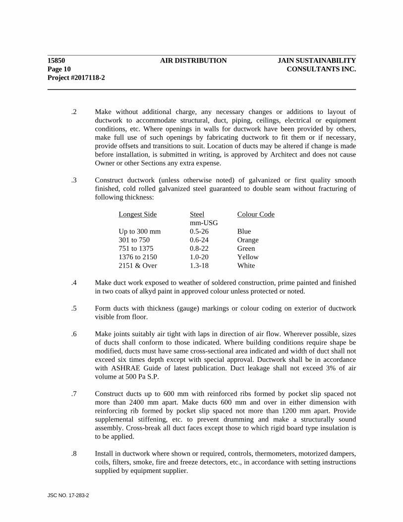
15850 AIR DISTRIBUTION JAIN SUSTAINABILITY Page 10 CONSULTANTS INC. Project #2017118-2
JSC NO. 17-283-2
.2 Make without additional charge, any necessary changes or additions to layout of ductwork to accommodate structural, duct, piping, ceilings, electrical or equipment conditions, etc. Where openings in walls for ductwork have been provided by others, make full use of such openings by fabricating ductwork to fit them or if necessary, provide offsets and transitions to suit. Location of ducts may be altered if change is made before installation, is submitted in writing, is approved by Architect and does not cause Owner or other Sections any extra expense.
.3 Construct ductwork (unless otherwise noted) of galvanized or first quality smooth
finished, cold rolled galvanized steel guaranteed to double seam without fracturing of following thickness:
Longest Side Steel Colour Code mm-USG Up to 300 mm 0.5-26 Blue 301 to 750 0.6-24 Orange 751 to 1375 0.8-22 Green 1376 to 2150 1.0-20 Yellow 2151 & Over 1.3-18 White .4 Make duct work exposed to weather of soldered construction, prime painted and finished
in two coats of alkyd paint in approved colour unless protected or noted. .5 Form ducts with thickness (gauge) markings or colour coding on exterior of ductwork
visible from floor. .6 Make joints suitably air tight with laps in direction of air flow. Wherever possible, sizes
of ducts shall conform to those indicated. Where building conditions require shape be modified, ducts must have same cross-sectional area indicated and width of duct shall not exceed six times depth except with special approval. Ductwork shall be in accordance with ASHRAE Guide of latest publication. Duct leakage shall not exceed 3% of air volume at 500 Pa S.P.
.7 Construct ducts up to 600 mm with reinforced ribs formed by pocket slip spaced not
more than 2400 mm apart. Make ducts 600 mm and over in either dimension with reinforcing rib formed by pocket slip spaced not more than 1200 mm apart. Provide supplemental stiffening, etc. to prevent drumming and make a structurally sound assembly. Cross-break all duct faces except those to which rigid board type insulation is to be applied.
.8 Install in ductwork where shown or required, controls, thermometers, motorized dampers,
coils, filters, smoke, fire and freeze detectors, etc., in accordance with setting instructions supplied by equipment supplier.
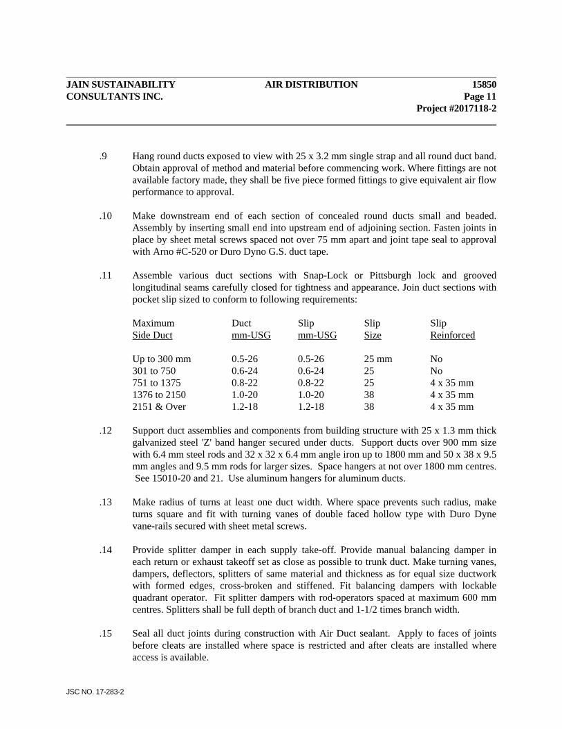
JAIN SUSTAINABILITY AIR DISTRIBUTION 15850 CONSULTANTS INC. Page 11 Project #2017118-2
JSC NO. 17-283-2
.9 Hang round ducts exposed to view with 25 x 3.2 mm single strap and all round duct band. Obtain approval of method and material before commencing work. Where fittings are not available factory made, they shall be five piece formed fittings to give equivalent air flow performance to approval.
.10 Make downstream end of each section of concealed round ducts small and beaded.
Assembly by inserting small end into upstream end of adjoining section. Fasten joints in place by sheet metal screws spaced not over 75 mm apart and joint tape seal to approval with Arno #C-520 or Duro Dyno G.S. duct tape.
.11 Assemble various duct sections with Snap-Lock or Pittsburgh lock and grooved
longitudinal seams carefully closed for tightness and appearance. Join duct sections with pocket slip sized to conform to following requirements:
Maximum Duct Slip Slip Slip Side Duct mm-USG mm-USG Size Reinforced Up to 300 mm 0.5-26 0.5-26 25 mm No 301 to 750 0.6-24 0.6-24 25 No 751 to 1375 0.8-22 0.8-22 25 4 x 35 mm 1376 to 2150 1.0-20 1.0-20 38 4 x 35 mm 2151 & Over 1.2-18 1.2-18 38 4 x 35 mm .12 Support duct assemblies and components from building structure with 25 x 1.3 mm thick
galvanized steel 'Z' band hanger secured under ducts. Support ducts over 900 mm size with 6.4 mm steel rods and 32 x 32 x 6.4 mm angle iron up to 1800 mm and 50 x 38 x 9.5 mm angles and 9.5 mm rods for larger sizes. Space hangers at not over 1800 mm centres. See 15010-20 and 21. Use aluminum hangers for aluminum ducts.
.13 Make radius of turns at least one duct width. Where space prevents such radius, make
turns square and fit with turning vanes of double faced hollow type with Duro Dyne vane-rails secured with sheet metal screws.
.14 Provide splitter damper in each supply take-off. Provide manual balancing damper in
each return or exhaust takeoff set as close as possible to trunk duct. Make turning vanes, dampers, deflectors, splitters of same material and thickness as for equal size ductwork with formed edges, cross-broken and stiffened. Fit balancing dampers with lockable quadrant operator. Fit splitter dampers with rod-operators spaced at maximum 600 mm centres. Splitters shall be full depth of branch duct and 1-1/2 times branch width.
.15 Seal all duct joints during construction with Air Duct sealant. Apply to faces of joints
before cleats are installed where space is restricted and after cleats are installed where access is available.
15850 AIR DISTRIBUTION JAIN SUSTAINABILITY Page 12 CONSULTANTS INC. Project #2017118-2
JSC NO. 17-283-2
.16 Install registers to manufacturer's direction. Supply and install baffles in diffusers to suit air pattern. Adjust grilles and registers to give required air throw and pattern.
.17 Provide extension collars for outlets, air guide vanes and other special features as
indicated or required including connections to equipment provided by Owner or other Sections. Transition ducts at not more than 30 degree slope to full size of each grille, register, louvre, coil or equipment.
.18 Install ductwork to clear structural members and any fire-proofing. Locate ducts to
permit their proper insulation where required. Do not remove or damage structural fireproofing. Leave space to permit insulation and fireproofing to be inspected and repaired.
.19 Provide flexible connections between equipment and duct work and where shown.
Provide suitable sheet metal rain guard for exterior fabric connections secured to fan only.
.20 Provide acoustic liner in all heat pumps supply and return ductwork as outlined below.
Where ducts are acoustic lined, sizes shown shall be inside liner. .21 Provide Duct Liner acoustic liner in duct work at each exhaust fan inlet connection for
not less than 3 m back from inlet including branches. Soundline 6 m of Make-Up Air Unit.
.22 Acoustic Treatment Installation:
.1 Adhere the liner to the interior sides of ductwork with a minimum of 75% coverage of an approved cold waterproof adhesive, Bakor #230-38.
.2 In addition, use mechanical fasteners, mechanical pins, adhered clips or adhered nylon pins. Do not drill or punch holes through the ductwork.
.3 Insulation shall be applied with all joints in close mechanical contact and all joints and voids shall be filled with an approved waterproof fire retardant mastic. Waterproof mastic shall be applied over all anchors where they pierce the covering.
.4. The ductwork must be enlarged in these areas to maintain the same cross-sectional area shown on the plans.
.5 Protect leading edge of liner with a 1" (25 mm) metal strip. .23 Provide pitot tube opening enclosures with cap and chain in ductwork for each supply,
return and exhaust system. Provide openings at all supply fan discharges, at return fan inlets and exhaust fan inlets, before and after silencers and heating coils in ductwork, and at main branch duct take-offs. Locate openings in straight duct runs. Provide a minimum of three holes per duct at each of above locations, and at not more than 450 mm centres.

JAIN SUSTAINABILITY AIR DISTRIBUTION 15850 CONSULTANTS INC. Page 13 Project #2017118-2
JSC NO. 17-283-2
.24 After final adjustments are made for air handling systems, lock each control device in position and visually indicate required setting. For splitter and balancing dampers, provide additional locking screw or bolt to approval.
3.2 BREECHINGS & STACKS .1 Provide stacks for press machine, luminator and for the extension of existing flues.
.2 Each stack shall be free standing type with necessary, elbows, supports, firestop spacers,
roof flashing, locking bands, roof braces and outlet cap to complete installation. Provide necessary counter-flashings to suit. Support horizontal sections from ceiling with 6.4 mm steel rods at 1 m centres. Connect each breeching to unit with separable joint and bolted adjustable length to approval.
.3 Each stack installation shall be carried out by a competent installing Subcontractor.
Prepare and submit detailed working drawings of installation for approval before work is started. Coordinate with domestic gas water heaters, see 15400. See 15010 re painting of exterior metal parts.
.4 Each gas vent system shall develop positive flow adequate to exhaust all flue gases to
outside atmosphere without condensation within vent or spillage at any appliance draft hood.
.5 Support new flue extensions to building structure with guy wires. 3.3 MAKE-UP AIR UNIT .1 Provide where shown a packaged make-up air unit. .2 Casing
.1 Set Casing on concrete perimeter base as shown. .2 Casing .1 Set casing on concrete perimeter base as shown. .3 Pipe unit to gas, water and drain lines. .4 Start Up .1 Start-up of unit, checking of controls, setting of switches, balancing of
drives, and balancing of all air flow shall be performed by service personnel who are trained in servicing this equipment and whose only function is service work.
.2 Two subsequent service calls at 3 months and 6 months shall be performed to check operation of unit and switches, and to check all filters.
15850 AIR DISTRIBUTION JAIN SUSTAINABILITY Page 14 CONSULTANTS INC. Project #2017118-2
JSC NO. 17-283-2
3.4 GAS PIPING AND SERVICE .1 Provide gas piping and connections as shown to gas equipment noted. Piping shall
conform to CGA #B149 and Ontario Gas Code, Regulation #244/89 as amended to date. Obtain local Gas Company approval of system, valving and sizing before starting piping. Install all work in compliance with CGA Natural Gas Appliance Installation Manual of latest date.
.2 Arrange and pay for replacement of gas meter/regulator assembly by local Gas Company to
approval. Meter/regulator assembly shall be sized to handle 12 million BTU/HR at 5 Psi for building services after metering and regulating.
.3 Pressure test gas piping with not less than 345 kPa air for at least 24 hours without decrease
in pressure. Check each joint with soap and water solution during test. Disconnect system during tests. Do not use oxygen for testing. Do not purge during school hours.
.4 Painting of gas piping will be done by another Section. .5 Provide gas piping necessary and connect up to make-up air. Provide shut-off valve on each
connection. Provide similar piping and valves to all infrared heaters. 3.5 OPERATE AND ADJUST SYSTEMS .1 Operate all systems to full capacity and verify proper, safe efficient operation of all parts
and each complete system. Oil motors and grease bearings before operating equipment. .2 When work is complete and systems are in operation, adjust valves, belt drives, controls,
dampers and thermostats so that there is even distribution of cooling, heating and ventilation air throughout. Turn over to Owner, necessary keys, handles and operating devices for each system.
.3 Each air handling system shall be balanced and air quantities per outlet listed and
forwarded to Engineer for checking and approval. Balancing Report shall be suitably bound, 216 x 279 mm size, six copies required. Clean or replace filters and leave systems in clean operating condition.
.4 Test and balance each air system such that air quantities at each outlet, diffuser, grille and
register are within 5% of design figures. Fan speeds, splitter and balancing dampers shall be adjusted to achieve these results. Prepare and submit a final balancing report for checking and approval.
JAIN SUSTAINABILITY AIR DISTRIBUTION 15850 CONSULTANTS INC. Page 15 Project #2017118-2
JSC NO. 17-283-2
.5 Testing and balancing of air handling systems and water systems (Heat Pumps and Hot Water Heating) shall be under supervision of qualified personnel. Balancing and testing shall be performed by trained personnel with records kept of each trial balance for supervision and approval.
.6 If spot checking systems reveals actual air quantities do not agree with air balance report,
this Section will be called upon to completely rebalance systems until satisfactory, without extra remuneration.
3.6 QUIET OPERATION .1 Each air handling system has been designed to be quiet in operation, N.C. 35 maximum.
It is responsibility of this Section to supply equipment and install systems to ensure noise levels will be maintained satisfactory to Consultant.
END OF SECTION

Electrical Specifications for
2017 ALTERATIONS TO EXISTING PLANT / BUILDING FOR NEW PRESS / LAMINATOR FOR:
SONOCO PRODUCTS COMPANY FLEXIBLE DIVISION Project No. 2017118-2
JSC Project No. 17-283-2
Issued for Tender
Date: January 23, 2018 Prepared by: Jain Sustainability Consultants Inc. 7405 East Danbro Crescent, 2nd Floor Mississauga, ON, L5N 6P8
JAIN SUSTAINABILITY ELECTRICAL SPECIFICATIONS TABLE OF CONSULTANTS INC. CONTENTS Project #2017118-2
JSC NO. 17-283-2
CONTENTS
SECTIONS TITLE 16010 Electrical General Requirements 16050 Basic Materials & Methods 16530 Emergency Lighting System
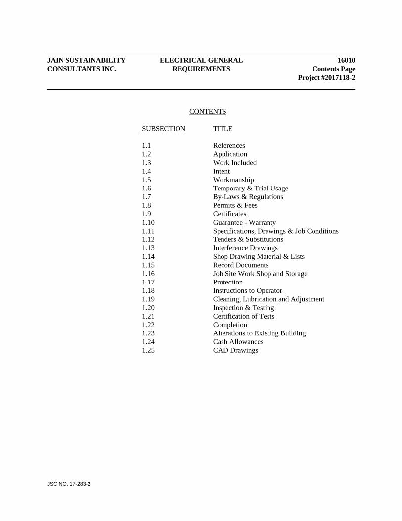
JAIN SUSTAINABILITY ELECTRICAL GENERAL 16010 CONSULTANTS INC. REQUIREMENTS Contents Page Project #2017118-2
JSC NO. 17-283-2
CONTENTS SUBSECTION TITLE 1.1 References 1.2 Application 1.3 Work Included 1.4 Intent 1.5 Workmanship 1.6 Temporary & Trial Usage 1.7 By-Laws & Regulations 1.8 Permits & Fees 1.9 Certificates 1.10 Guarantee - Warranty 1.11 Specifications, Drawings & Job Conditions 1.12 Tenders & Substitutions 1.13 Interference Drawings 1.14 Shop Drawing Material & Lists 1.15 Record Documents 1.16 Job Site Work Shop and Storage 1.17 Protection 1.18 Instructions to Operator 1.19 Cleaning, Lubrication and Adjustment 1.20 Inspection & Testing 1.21 Certification of Tests 1.22 Completion 1.23 Alterations to Existing Building 1.24 Cash Allowances 1.25 CAD Drawings
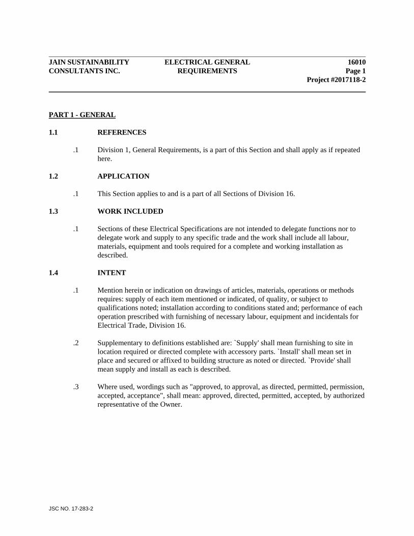
JAIN SUSTAINABILITY ELECTRICAL GENERAL 16010 CONSULTANTS INC. REQUIREMENTS Page 1 Project #2017118-2
JSC NO. 17-283-2
PART 1 - GENERAL 1.1 REFERENCES
.1 Division 1, General Requirements, is a part of this Section and shall apply as if repeated here.
1.2 APPLICATION .1 This Section applies to and is a part of all Sections of Division 16. 1.3 WORK INCLUDED .1 Sections of these Electrical Specifications are not intended to delegate functions nor to
delegate work and supply to any specific trade and the work shall include all labour, materials, equipment and tools required for a complete and working installation as described.
1.4 INTENT .1 Mention herein or indication on drawings of articles, materials, operations or methods
requires: supply of each item mentioned or indicated, of quality, or subject to qualifications noted; installation according to conditions stated and; performance of each operation prescribed with furnishing of necessary labour, equipment and incidentals for Electrical Trade, Division 16.
.2 Supplementary to definitions established are: `Supply' shall mean furnishing to site in
location required or directed complete with accessory parts. `Install' shall mean set in place and secured or affixed to building structure as noted or directed. `Provide' shall mean supply and install as each is described.
.3 Where used, wordings such as "approved, to approval, as directed, permitted, permission,
accepted, acceptance", shall mean: approved, directed, permitted, accepted, by authorized representative of the Owner.

16050 ELECTRICAL GENERAL JAIN SUSTAINABILITY Page 2 REQUIREMENTS CONSULTANTS INC. Project #2017118-2
JSC NO. 17-283-2
.4 Equipment provided under this Division shall conform to applicable standards and regulations of the following organizations:
Canadian Standards Association (CSA) Underwriter's Laboratories of Canada (ULC) Canadian Electrical Code (CEC) Electrical Inspection Department of Ontario Hydro Electrical Safety Code (ESC) Canadian Underwriters Association (CUA) National Building Code (NBC) Ontario Building Code (OBC) 1.5 WORKMANSHIP .1 Workmanship and method of installation shall conform to best standards and practice.
Where required by local or other By-Laws and Regulations, tradesmen shallbe licensed in their trade.
1.6 TEMPORARY & TRIAL USAGE .1 Temporary or trial usage of any equipment or materials shall not be construed as
evidence of acceptance of same and no claim for damage shall be made for injury to or breaking of any part of such work which may be so used..
1.7 BY-LAWS & REGULATIONS .1 Work shall conform with latest rules, regulations and definitions of Canadian Electrical
Code and applicable Municipal and Provincial Codes and Regulations, and with requirements of other authorities having jurisdiction in the area where work is to be performed. Minor changes required by an authority having jurisdiction shall be carried out without change to the Contract amount. Standards established by drawings and specifications shall not be reduced by applicable codes or regulations.
1.8 PERMITS & FEES .1 File Contract Drawings with proper authorities and obtain their approval of installation
and permits for same before proceeding with work. Prepare and submit necessary detailed shop drawings as required by Authorities.
.2 Pay all fees in connection with examination of drawings, permits, inspections and final
certificate of approval.
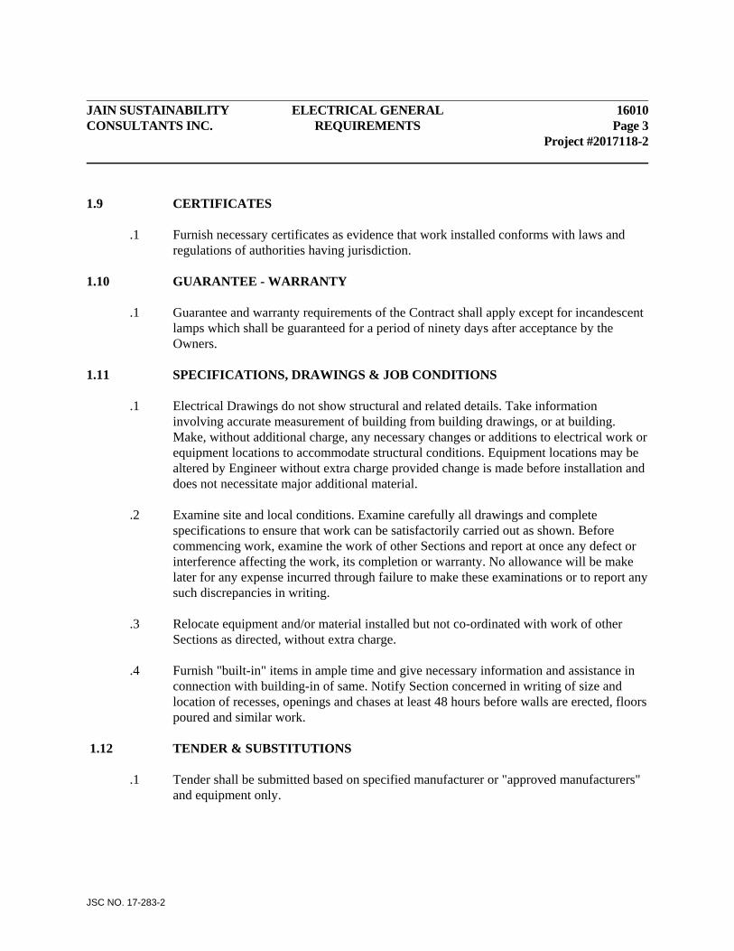
JAIN SUSTAINABILITY ELECTRICAL GENERAL 16010 CONSULTANTS INC. REQUIREMENTS Page 3 Project #2017118-2
JSC NO. 17-283-2
1.9 CERTIFICATES .1 Furnish necessary certificates as evidence that work installed conforms with laws and
regulations of authorities having jurisdiction. 1.10 GUARANTEE - WARRANTY .1 Guarantee and warranty requirements of the Contract shall apply except for incandescent
lamps which shall be guaranteed for a period of ninety days after acceptance by the Owners.
1.11 SPECIFICATIONS, DRAWINGS & JOB CONDITIONS .1 Electrical Drawings do not show structural and related details. Take information
involving accurate measurement of building from building drawings, or at building. Make, without additional charge, any necessary changes or additions to electrical work or equipment locations to accommodate structural conditions. Equipment locations may be altered by Engineer without extra charge provided change is made before installation and does not necessitate major additional material.
.2 Examine site and local conditions. Examine carefully all drawings and complete
specifications to ensure that work can be satisfactorily carried out as shown. Before commencing work, examine the work of other Sections and report at once any defect or interference affecting the work, its completion or warranty. No allowance will be make later for any expense incurred through failure to make these examinations or to report any such discrepancies in writing.
.3 Relocate equipment and/or material installed but not co-ordinated with work of other
Sections as directed, without extra charge. .4 Furnish "built-in" items in ample time and give necessary information and assistance in
connection with building-in of same. Notify Section concerned in writing of size and location of recesses, openings and chases at least 48 hours before walls are erected, floors poured and similar work.
1.12 TENDER & SUBSTITUTIONS .1 Tender shall be submitted based on specified manufacturer or "approved manufacturers"
and equipment only.
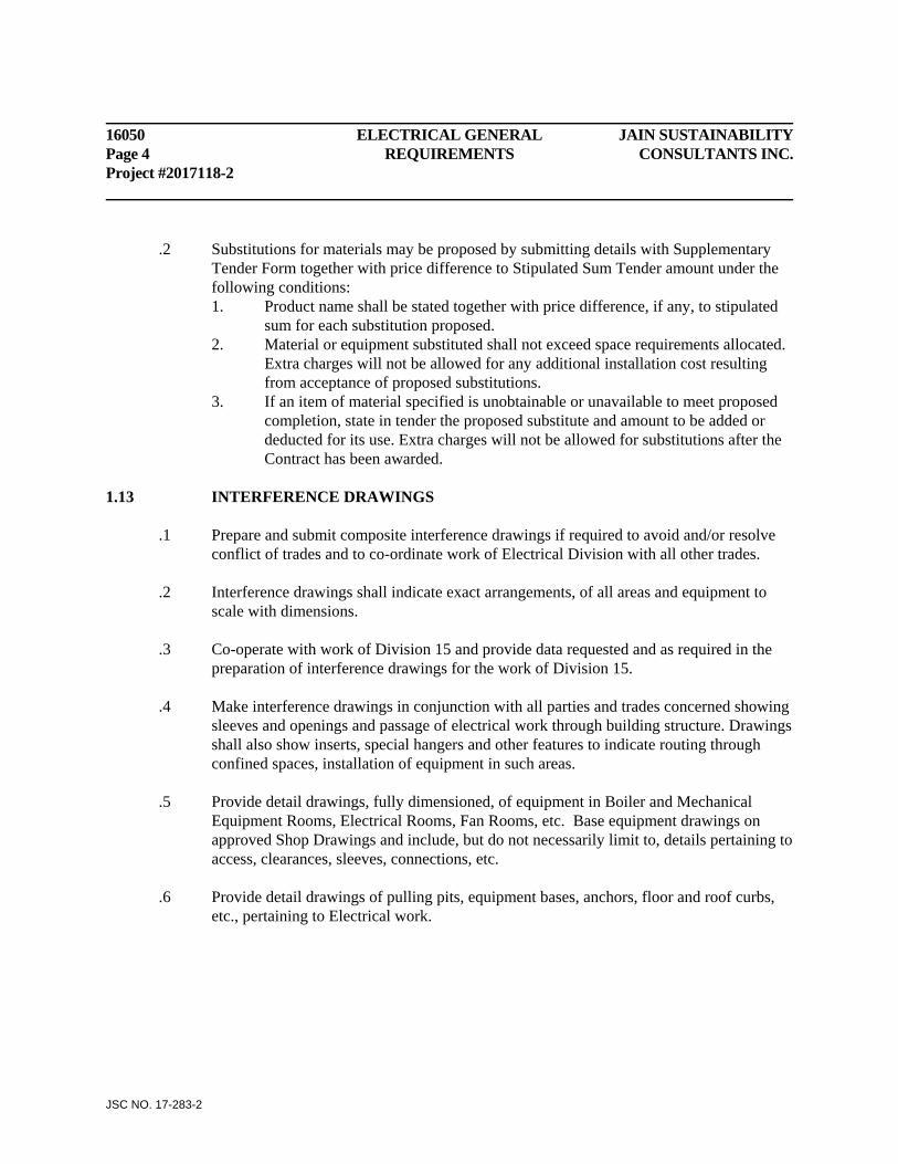
16050 ELECTRICAL GENERAL JAIN SUSTAINABILITY Page 4 REQUIREMENTS CONSULTANTS INC. Project #2017118-2
JSC NO. 17-283-2
.2 Substitutions for materials may be proposed by submitting details with Supplementary Tender Form together with price difference to Stipulated Sum Tender amount under the following conditions:
1. Product name shall be stated together with price difference, if any, to stipulated sum for each substitution proposed.
2. Material or equipment substituted shall not exceed space requirements allocated. Extra charges will not be allowed for any additional installation cost resulting from acceptance of proposed substitutions.
3. If an item of material specified is unobtainable or unavailable to meet proposed completion, state in tender the proposed substitute and amount to be added or deducted for its use. Extra charges will not be allowed for substitutions after the Contract has been awarded.
1.13 INTERFERENCE DRAWINGS .1 Prepare and submit composite interference drawings if required to avoid and/or resolve
conflict of trades and to co-ordinate work of Electrical Division with all other trades. .2 Interference drawings shall indicate exact arrangements, of all areas and equipment to
scale with dimensions. .3 Co-operate with work of Division 15 and provide data requested and as required in the
preparation of interference drawings for the work of Division 15. .4 Make interference drawings in conjunction with all parties and trades concerned showing
sleeves and openings and passage of electrical work through building structure. Drawings shall also show inserts, special hangers and other features to indicate routing through confined spaces, installation of equipment in such areas.
.5 Provide detail drawings, fully dimensioned, of equipment in Boiler and Mechanical
Equipment Rooms, Electrical Rooms, Fan Rooms, etc. Base equipment drawings on approved Shop Drawings and include, but do not necessarily limit to, details pertaining to access, clearances, sleeves, connections, etc.
.6 Provide detail drawings of pulling pits, equipment bases, anchors, floor and roof curbs,
etc., pertaining to Electrical work.
JAIN SUSTAINABILITY ELECTRICAL GENERAL 16010 CONSULTANTS INC. REQUIREMENTS Page 5 Project #2017118-2
JSC NO. 17-283-2
1.14 SHOP DRAWING MATERIAL & LISTS .1 Prepare and submit shop drawings and lists of materials for review in accordance with
Architectural Sections. Make submittals of more than two pages in booklet form. Individual and loose drawings will not be accepted for review.
.2 Prior to equipment fabrication, delivery or installation, submit complete lists of materials
proposed, indicating manufacturer, catalogue numbers and complete performance data. .3 Review of Shop Drawings by Consultant is for sole purpose of ascertaining conformance
with general design concept. This review shall not mean that Architect and/or Engineer approves detail design inherent in Shop Drawings, responsibility for which shall remain with Contractor and such review shall not relieve Contractor of his responsibility for meeting all requirements of Contract Documents. Contractor is responsible for dimensions to be confirmed and correlated at site, for information that pertains solely to fabrication processes or to techniques of construction and installation and for co-ordination of work with all trades.
.4 Shop drawings transmitted via facsimile (fax) machines, or copies of same, will not be
accepted for review. 1.15 RECORD DOCUMENTS
.1 Conform to General Requirements. Maintain at least 2 sets of documents and clearly mark on same as job progresses, changes and deviations from work shown so that on completion Owner will have records of exact location of ducts and equipment and record of material and equipment changes.
.2 Contractor shall obtain clean set of prints from Consultant at start of Contract Work and
shall keep these prints up-to-date at jobsite, accurately recording all changes made on project and locating all services, equipment, etc. which may have been shown only diagrammatically on Contract Documents.
.3 Contractor shall ensure that as-built information is accurately recorded and shall check same.
As-Built drawings shall be reviewed with Consultant at each jobsite meeting.
.4 Upon completion of Contract Work, prior to Substantial Performance inspection and after final review with Consultants, Contractor shall neatly transfer recorded information and make final As-Built submission to Consultant for review in the following form: - One (1) set of clean, legible prints. - One (1) ACAD 2017 format drawings. Files shall retain all setting (layers, line
types, scales colors, etc) as used in the drawing files (produced) by consultant.
16050 ELECTRICAL GENERAL JAIN SUSTAINABILITY Page 6 REQUIREMENTS CONSULTANTS INC. Project #2017118-2
JSC NO. 17-283-2
.5 After Record Drawings have been reviewed, revised if necessary until acceptable to the consultant. Deliver drawings in the form of CD (CAD + PDF) and three (3) sets of prints taken from that CD to Owner.
1.16 JOB SITE WORK SHOP AND STORAGE .1 Supply job site office, workshop, tools, scaffolds and material storage as required to
complete the work of this Division. Location of temporary buildings, use of space on site or within building shall be to later direction.
1.17 PROTECTION .1 Securely plug or cap open ends of electrical raceways or equipment to prevent entry of
dirt, dust, debris, water, snow or ice. Clean all equipment inside and outside before testing.
.2 Equipment stored on site shall be protected from weather and kept dry and clean at all
times. Take care to avoid corrosion of metal parts. .3 Protect work installed from damage. Secure all unfinished or loose work to prevent
movement. 1.18 INSTRUCTIONS TO OPERATOR .1 Contractor will be responsible for collecting and organizing three (3) copies of all data,
operating instructions, trouble-shooting instructions, parts lists, parts diagrams, evidence of all tests, maintenance manuals, etc. and assembling them in neat manuals. This shall include (however not be limited to) all reviewed shop drawings, manufacturer’s operation manuals, complete fire alarm verification report, final ESA inspection certificate, emergency lighting levels plot and verification letter, panel directories and lamp list.
.2 Contractor shall also collect from Subtrades and Suppliers all Guarantees/Warranties
specified. Check that starting date (date of Substantial Performance of entire project) and extent of each guarantee/warranty are clearly indicated. Check also that all guarantees/warranties indicate Supplier’s Name or Subcontractor’s Name as appropriate together with contact phone number. Assemble neatly in labeled section of each manual.
.3 Submit manuals to Consultant for approval prior to requesting Substantial Performance
inspection.
JAIN SUSTAINABILITY ELECTRICAL GENERAL 16010 CONSULTANTS INC. REQUIREMENTS Page 7 Project #2017118-2
JSC NO. 17-283-2
.4 Arrange for on-site instruction by various Manufacturers where considered necessary by Consultant, at no additional cost to Owner.
1.19 CLEANING, LUBRICATION AND ADJUSTMENT .1 Immediately prior to completion of work:
1. Remove all dust, dirt and other foreign matter from internal surfaces of enclosed electrical apparatus and equipment.
2. Remove all temporary protective coverings and coatings, temporary labels. 3. Clean, repair, lubricate and adjust all mechanism and moveable parts of apparatus
and equipment leaving it in new condition and operating properly. 4. Balance demand loads for service and distribution feeders within 5 percent upon
completion of work and after the building is in full operation. 1.20 INSPECTION AND TESTING .1 Systems, equipment, and all major items of material shall be tested to the satisfaction of
the Architect, and as required to establish compliance with plans and specifications, and with the requirements for the Supply and Inspection Authorities.
.2 Faulty and defective equipment shall be replaced with new materials. Conductors which
are found to be shorted or grounded, or to have less than proper insulation resistance, shall be replaced with new conductors.
.3 Tests shall include but are not limited to the following:
1. Test of secondary voltage cables shall include megger tests to establish proper insulation resistance, and phase-to-ground resistance of cables.
2. Proper functioning of all systems. 3. Polarity tests - to establish proper polarity connections to all sockets and
receptacles. 4. Megger tests to establish proper insulation resistances and phase to ground
resistance of wiring.
1.21 CERTIFICATE OF TESTS .1 When work is complete submit three copies of test results and a signed statement listing
all tests that have been performed as required by specifications and manufacturer's instructions.
1.22 COMPLETION .1 Provide receipts from designated representative of Owner for portable and loose materials
(e.g. spare fuses, fixture relamping equipment and the like).
16050 ELECTRICAL GENERAL JAIN SUSTAINABILITY Page 8 REQUIREMENTS CONSULTANTS INC. Project #2017118-2
JSC NO. 17-283-2
.2 Provide copy of final inspection certificate from Electrical Inspection Authority. .3 Perform tests and provide documentation as further described herein. .4 Provide Record Drawings to approval. .5 Provide manufacturers corrected "as built" shop drawings for all major electrical items
and systems, including all shop drawings returned for modifications. 1.23 ALTERATIONS TO EXISTING BUILDING .1 Note that certain alterations and structural changes are to be made to existing building.
Architectural drawings and site are to be examined to determine extent of alterations affecting existing electrical systems. Where existing conduits and wires run through areas to be altered, to feed other parts of existing building, they shall be re-routed and reconnected to maintain their original function. Drawings do not necessarily indicate outlets, switches, receptacles, and the like, and other electrical equipment which are required to be relocated or abandoned. Provide decorative blanking cover plates for obsolete outlet boxes remaining.
.2 Electrical services and auxiliary services (fire alarm, P.A. intercom, and the like) shall be
maintained continuously without interruption. Interruptions to services shall be confined to periods of time to be designated by Architect, and/or Owner’s designated representative. Include in tender for temporary connections, overtime labour charges, and such related allowances in order to conform with these conditions.
.3 The Electrical Contractor is responsible for removal, reinstallation, cutting and patching
of ceiling and walls as required in the existing building. .4 Cutting directly related to electrical work, regardless of whether such work occurs in new
or existing construction, shall be coordinated and paid for by Electrical Subcontractor involved, under supervision of Contractor.
.5 Where existing electrical items or systems are demolished and removed from existing
construction assemblies, Electrical Subcontractor involved shall be responsible for infilling entire hole left after removal of item or system with new construction assembly to match existing. Where new electrical items or systems are installed through existing construction assemblies, Electrical Subcontractor involved shall be responsible for properly sized and accurate cutting of existing construction assembly to allow installation of new work.
JAIN SUSTAINABILITY ELECTRICAL GENERAL 16010 CONSULTANTS INC. REQUIREMENTS Page 9 Project #2017118-2
JSC NO. 17-283-2
1.24 CASH ALLOWANCES .1 Refer to Division 1 for Cash Allowances. 1.34 CAD DRAWINGS
.1 If required for coordination purposes or for As-Builts, the Contractor may obtain Design
Drawings from the Consultant after completing the required Document Request Form and paying a handling charge of $75 + HST per drawing.
END OF SECTION
JAIN SUSTAINABILITY BASIC MATERIALS & METHODS 16050 CONSULTANTS INC. Contents Page Project #2017118-2
JSC NO. 17-283-2
CONTENTS SUBSECTION TITLE PART 1 - GENERAL 1.1 References 1.2 Materials 1.3 Material Acceptance PART 2 - PRODUCTS 2.1 Raceways 2.2 Wire & Cable 2.3 Devices 2.4 Devices - Specialized 2.5 Device Cover Plates 2.6 Panelboards 2.7 Switches
2.8 Fuses 2.9 Dry Type Transformers
PART 3 - EXECUTION 3.1 Equipment Locations 3.2 Mounting Heights 3.3 Holes & Drilling 3.4 Cutting & Patching 3.5 Excavation & Backfill 3.6 Concrete Work 3.7 Hangers & Inserts 3.8 Painting …..Continued
16050 BASIC MATERIALS & METHODS JAIN SUSTAINABILITY Contents Page CONSULTANTS INC. Project #2017118-2
JSC NO. 17-283-2
CONTENTS SUBSECTION TITLE PART 3 – EXECUTION (Cont’d) 3.9 Nameplates & Schedules 3.10 Branch Circuit Wiring & Feeder Cables 3.11 Conduit, Raceways and Wireways 3.12 Wire & Cable 3.13 Outlet, Junction & Pull Boxes 3.14 Access Doors & Access Markers 3.15 Panelboards 3.16 Inspection & Testing
3.17 Electric Work For Other Divisions 3.18 Grounding – General 3.19 Fireproofing & Sealing
JAIN SUSTAINABILITY BASIC MATERIALS & METHODS 16050 CONSULTANTS INC. Page 1 Project #2017118-2
JSC NO. 17-283-2
PART 1 - GENERAL 1.1 REFERENCES .1 Conform to Section 16010 - Electrical - General Requirements. 1.2 MATERIALS .1 Materials shall be new, of Canadian manufacture where available, first quality and
uniform throughout. Submit tender based on the use of materials and equipment specified, or on the listed acceptable alternate equipment as further detailed.
.2 Electrical materials shall be C.S.A. approved and be so labeled. Material not C.S.A.
approved shall receive acceptance for installation by Ontario Hydro Special Inspections Branch before delivery, and modifications and charges required for suchf acceptance shall be included in work of this Section. Material shall not be installed or connected to the source of electrical power until approval is obtained.
.3 Confirm capacity, ratings and characteristics of equipment items being provided to
supply power to equipment provided under other Sections of the work. Resolve discrepancies before such items are purchased.
1.3 MATERIAL ACCEPTANCE .1 Acceptance of materials installed presumes that materials have not been damaged or
exposed to conditions that would adversely affect performance and life expectancy.
.2 If in the opinion of the Architect, materials have sustained damage, or have been exposed to abnormal conditions it shall be the responsibility of the Contractor to have such tests performed as deemed necessary by the Architect to establish condition and therefore, acceptability of installed materials.
PART 2 - PRODUCTS 2.1 RACEWAYS .1 Rigid galvanized steel conduit shall comply with CSA Specification C22.2 No. 45. .2 Electrical metallic tubing (EMT) shall comply with CSA Specification C22.2 No. 83.
Connectors and couplings to be forged steel. Connectors to have factory-installed insulated throats.
.3 Rigid PVC conduit shall comply with CSA Specification C22.2 No. 136.
16050 BASIC MATERIALS & METHODS JAIN SUSTAINABILITY Page 2 CONSULTANTS INC. Project #2017118-2
JSC NO. 17-283-2
.4 Watertight flexible conduit: "Sealtite" PVC jacketed flexible steel with Hubbell-Kellum strain relief grips; shall comply with CSA Standard C22.2 No. 56.
2.2 WIRE & CABLE .1 Branch wire and cable shall comprise copper conductors, sized as noted, rated 90 deg. C.,
600 volt minimum flame retardant insulation, and CSA approved for application. .2 Wire and cable installed in conduit shall be thermoplastic insulated Type T90 - Flame
retardant and comply with latest CSA Specification. .3 Use Electrovert "Z-Type" code markers for control & communication conductors. 2.3 DEVICES .1 Wiring devices unless otherwise specified herein, or noted, shall be as manufactured by
Hubbell, Leviton, P & S, Bryant Electric. .2 Switches for 347 volt branch lighting circuits, generally shall be A.C. "Quiet Type" rated
20 amp. 347 volt, totally enclosed phenolic housing Hubbell HBL18221 Series, white/beige toggle handle.
.3 Double Pole lighting switches shall be connected to 2 pole circuit breakers. .4 Key-operated switches shall be Hubbell 1221-L Series of the types listed above, except
key-operated, and shall be keyed-alike. .5 Standard 15 amp. 125 volt duplex receptacles generally shall be Specification grade
Hubbell Cat. No.5262, white/beige CSA #5-15R. .6 Standard Duplex receptacles indicated to have `split-feed' shall be two-circuit type wired
and connected to a 2 pole common trip circuit breaker in associated panelboard. Orientation of common circuit shall be similar throughout project.
.7 Special purpose receptacles as noted on the drawings shall be Hubbell Conforming to
CSA configurations (Table 46 and Table 47 of Canadian Electrical Code) for non-locking and locking receptacles. Provide attachment cap for each special purpose receptacle.
.8 "Range" receptacles shall be CSA Type 14-50R, 50 amp. 3 pole, 4 wire, grounding
125/250V flush receptacle. Provide the above with 5 foot rubber cord set, 50 amp. and connect equipment.

JAIN SUSTAINABILITY BASIC MATERIALS & METHODS 16050 CONSULTANTS INC. Page 3 Project #2017118-2
JSC NO. 17-283-2
.9 Receptacles with integral ground fault interrupter shall be Hubbell No. GF-5262 or GF-52562TR for tamper resistant type with matching stainless steel faceplate.
.10 Isolated ground receptacles shall be Pass & Seymour #IG26262GRY, grey finish or
TRIG26262 for tamper resistant type. .11 Clock receptacles shall be recessed fitting, Leviton 688W. .12 Red services receptacles on MCPs and as noted on drawings shall be labeled “Custodial”
and be Hubbell #5262-RD. .13 Dimmer switches for incandescent lighting shall be electronic type c/w heat sink as
required, radio interference suppression, toggle type for ratings 1000W and smaller. Leviton 81500/slide series or Ideal 56-1000 series.
2.4 DEVICES - SPECIALIZED .1 Hand-dryers shall be automatic surface mounted ADA compliant type to mounting height
as directed by Architect on site, Cast Iron Cover fixed nozzle to include heavy duty vandal-resistant grille. World Dryer #NOVA 4, 120V, 1800 W.
.2 Provide for each location shown on drawings, a 12” diameter to match existing and to be
connected to existing Simplex central clock system. 2.5 DEVICE COVER PLATES .1 Switch and receptacle and other device faceplates for flush mounted devices, generally
shall be single or multi-gang as required, type 301, stainless steel, #4 brushed finish with removable protective covering.
.2 Weatherproof covers shall be while-in-use type polycarbonate body, cover and plates,
conform to NEMA3R. Hubbell # WP826MP. .3 Cover plates for other devices such as flush fan controls, telephone, etc., shall be stainless
steel to match above. 2.6 PANELBOARDS .1 Panelboards as scheduled, shall comprise "Branch" panelboards, with fixed bolted
connection thermal-magnetic, quick-make, quick-break, 40oC, calibrated ULC rated `SWD' switching duty, molded-case circuit breaker branches. "Plug-in" breakers are not acceptable. Multipole breakers shall be common trip type.
16050 BASIC MATERIALS & METHODS JAIN SUSTAINABILITY Page 4 CONSULTANTS INC. Project #2017118-2
JSC NO. 17-283-2
.2 Panelboards shall include the following features: .1 Flush or surface trim as noted. .2 Concealed hinges. .3 Combination catch and lock semi flush tumbler type - all keyed alike. .4 Adjustable self-positioning trims. .5 Plain trims not displaying any names or Symbols. "Vault" type handles shall not be used except in unfinished areas. .6 Typed schedules of circuits indicating equipment and area controlled on the
backs of panel doors, in a steel trim pocket, covered with transparent non-inflammable plastic.
.7 Insulated neutral block. .8 Supplementary ground block. .9 Copper Bus. .10 Isolated ground bar, as noted. .11 Surge-suppression system, as noted. .12 Sprinklerproof .3 Power and Distribution type panelboards shall be breaker type, as scheduled on the
drawings. .4 Fusible switch type panelboards shall be complete with suitable fuses as specified under
"Fuses". .5 Unless noted otherwise, panelboards with main breakers or remote controlled switches
shall be provided with an indicating pilot lamp flush mounted in top of face trim which shall be connected to a 15 amp. circuit in the panelboard which shall be locked on and shall serve to indicate when the main breaker is in the closed position. Pilot lamp units shall be LED type or other approved types designed to provide maximum lamp life. Provide lamacoid nameplate to identify main breaker.
.6 Panelboards of the types scheduled shall comprise the following:
General Note for All Types: Refer to Drawings for more information about electrical
panels and comply accordingly.
Type 1 Branch panelboard circuit breaker type 120/208 volt, 3 phase, 4 wire mains, minimum interrupting rating of 10,000 amps. RMS Asymmetrical at 120 volts.
JAIN SUSTAINABILITY BASIC MATERIALS & METHODS 16050 CONSULTANTS INC. Page 5 Project #2017118-2
JSC NO. 17-283-2
Type 2 Branch panelboard circuit breaker type 347/600 volt, 3 phase, 4 wire mains minimum interrupting rating of 14,000A. RMS symmetrical at 600 volts for 3 pole, and 18,000A RMS symmetrical at 347 volts for single pole circuit breakers and 35,000 A RMS symmetrical at 600V for panels located within the Main Electrical Room. Type 3 Power distribution panelboard (CDP), circuit breaker type 347/600 volt, 3 phase, 4 wire mains, minimum interrupting rating of 22,000A, RMS symmetrical at 600 volt. Type 4 Power distribution panelboard (CDP), circuit breaker type 120/208 volt, 3 phase, 4 wire mains, minimum interrupting rating of 35,000A, RMS symmetrical at 208 volt.
.7 Acceptable Manufacturers are: .1 Cutler-Hammer .2 Square `D' .3 Siemens 2.7 SWITCHES .1 Provide fusible and non-fusible switches, NEMA Type `HD' with quick-make,
quick-break contacts, horsepower-rated where required, to match the motor protected. Provide holders to accept specified fuses. Switches to include mechanical cover interlocks and line side barriers.
.2 Where applicable and available, switches shall be CSA "Approved For High Service Factor".
.3 Provide safety disconnect switches adjacent to motors and other equipment when
required by regulations. 2.8 FUSES .1 Provide fuse holders in fusible equipment with a complete set of proper size Form 1,
HRC Nema J or L current limiting fuses. Fusible equipment so provided shall be adapted to reject CSA Standard C22.2 No. 59 fuses. Fuses shall be Federal Pioneer - "Econolim".
.2 Provide one complete set of spare fuses for each rating and type used, unless otherwise
scheduled. .3 Apply Thomas & Betts "Kopr/Shield" conductive anti-seize compound to all fuse ferrules
and holders.
16050 BASIC MATERIALS & METHODS JAIN SUSTAINABILITY Page 6 CONSULTANTS INC. Project #2017118-2
JSC NO. 17-283-2
2.9 DRY TYPE TRANSFORMERS
.1 Dry-type transformers shall be three-phase indoor dry-type, 60 cycle type ANS, natural draft, air-cooled, manufactured in accordance with CEMA Specification L2, CSA C22.2 No. 47, CSA C9-1966, ASA C57.12, NEMA TRI, and latest revision thereof. They shall be metal enclosed in ventilated code gauge steel enclosures, finished ASA No. 61. Overall dimensions of transformers shall not exceed those noted on the drawings.
.2 Windings for three phase transformers shall be copper 1.2 KV class, 10 KV B.I.L., high
voltage winding delta-connected 600 volt; low voltage winding 208/120 & 220/120 volt wye connected. Primary winding shall include four 2-1/2 percent taps arranged two above and two below, normal voltage. Insulation to be rated Class B - 80 deg. C. Unit design shall incorporate a vibration isolation system.
.3 Transformers shall have an electrostatic shield located between the primary and
secondary windings. Terminate the shield at an isolated terminal in the terminal connection area.
.4 Transformer shall be high-efficiency type, meeting maximum loss limits specified in
CSA C802-94. .5 Transformers shall be manufactured by:
.1 Rex Manufacturing .2 Square ‘D’ .3 Hammond Manufacturing .4 Delta PART 3 - EXECUTION 3.1 EQUIPMENT LOCATIONS .1 Approximate locations of electrical equipment, fixtures switches, outlets, and the like, are
given on the drawings. Refer to the architectural drawings and room elevations for application. In absence of definite detail exact location of outlets shall be determined on site as work progresses. Local switches for lighting shall generally be installed on the lock side of doors. Verify switch locations on the site.
.2 Device plates shall cover opening left for outlet box, and plates shall be attached to boxes
in an approved manner. Outlets and fixtures are to be located symmetrically, (i.e. centred in wall panels, ceiling panels or tiles, columns, between and above doors and the like).
JAIN SUSTAINABILITY BASIC MATERIALS & METHODS 16050 CONSULTANTS INC. Page 7 Project #2017118-2
JSC NO. 17-283-2
.3 The right is reserved to alter the location of equipment and outlets a distance of up to 3 metres without involving a change to the Contract amount, providing notice is given prior to installation.
3.2 MOUNTING HEIGHTS .1 Mounting heights of outlets, top of outlet to finished floor, except for exposed masonry
construction, shall generally be as follows: Lighting Switches - 1200 mm Receptacles - 400 mm above finished floor Television Outlets - 400 mm Telephone Outlets - 400 mm Panelboards - 2000 mm to top of trim for standard panels. Clocks - 2000 mm or 300 mm below ceiling. Fire Alarm Equipment- As per CAN /ULC – S 524 Standard. 3.3 HOLES & DRILLING
.1 Pneumatic hammers and percussion drills are prohibited. .2 Where not sleeved, make holes through concrete walls and floors by core-drill only.
Obtain Architect's approval before drilling. .3 Seal holes and sleeves through floors to serve as water dam.
3.4 CUTTING & PATCHING .1 Layout and install work in advance of other Sections for all new work. Bear all costs
resulting from failing to comply with this requirement. .2 Pay for cutting and patching and making good as required for work of this Division by
reason of faulty or late work. Employ appropriate trades already engaged on the site to perform such cutting, patching and making good existing walls, floor, ceiling, etc. Before commencing, obtain Architect's approval for extent and nature of cutting. Make good, disturbed surfaces to the Architect's approval.
3.5 EXCAVATION & BACKFILL .1 Provide necessary excavating and backfilling inside and outside building required for
work of this Division, performed as specified under another Division of the work, except as modified below.
.2 Keep excavations free from water, pump as necessary.
16050 BASIC MATERIALS & METHODS JAIN SUSTAINABILITY Page 8 CONSULTANTS INC. Project #2017118-2
JSC NO. 17-283-2
.3 Excavation for underground services shall be to required depths and dimension and shall be prepared as required, so that no portion of any conduit, bears directly against any rock or other hard surface.
.4 Remove and dispose of all surplus excavated material. .5 Backfill promptly after approval of work. Prevent damage to or displacement of walls,
piping, conduits, waterproofing and other work.
.6 For direct buried conduit and cable in all soil conditions excavate to 150 mm (6") below and a minimum of 200 mm (8") to either side of the cable run. Fill back with a bedding of sand.
.7 Backfill trenches within building, with clean sharp sand in individual layers of maximum
150 mm (6") thickness, compacted to a density of 100% Standard Proctor. Hand compact the first layers up to a compacted level of minimum one foot. Hand or machine compact the balance up to grade, using approved equipment.
.8 Backfill trenches outside buildings with granular `A' gravel in layers not exceeding 150
mm (6") thickness, compacted to 100% Standard Proctor density up to grade level; manual compaction up to 450 mm (18") and mechanical compaction, using approved equipment, for the balance.
.9 Make good work where damaged by excavation and filling work of this Division. Repair
any subsequent settlement of fill placed under this Division and pay all costs in replacement of other work damaged by such settlement and restoration.
3.6 CONCRETE WORK .1 Provide concrete work where required for work of this Division in accordance with
applicable requirements specified in Concrete Division 3. .2 Provide concrete Lighting Standard Bases, required for the work of this Division. Refer
to detail on drawings. .3 Provide concrete Duct Banks required for the work of this Division. Refer to detail on
drawing for typical construction details. .4 Reinforced concrete duct banks shall be keyed into sides of foundation walls. Extend and
connect reinforcing steel of duct banks to reinforcing steel of foundation wall construction to prevent failure at the junction of the pipe support and wall.
JAIN SUSTAINABILITY BASIC MATERIALS & METHODS 16050 CONSULTANTS INC. Page 9 Project #2017118-2
JSC NO. 17-283-2
.5 Provide 100 mm (4”) high housekeeping pads for all floor mounted electrical equipment, such as switchboard, distribution panels and transformer, etc.
3.7 HANGERS & INSERTS .1 Provide necessary hangers and inserts for work of this Division. .2 Fasten to cast-in place concrete by suitable drilled or cast-in inserts. .3 Fasten to structural steel using bolts or welded fasteners.
.4 Do not use wood, chain, wire lashings, strap or grappler bar hangers except where noted or detailed.
.5 Support fixtures independently of ceiling suspension systems. Provide additional
supports as required, which shall be fastened to building structure steel members, joists, beams, etc., but not metal pan or roof decking. Material for additional supports and their installation shall comply with requirements of U.L.C. Refer to "List of Equipment and Materials" Vol. 2, and "Supplement" for application to rated assemblies.
.6 Support outlet and junction boxes independently of the conduits running to them where
required by electrical code and where deemed necessary by the Architect, use steel angle brackets or steel rods to support outlets and fixtures, to the building structure.
.7 Drilled fastenings to concrete shall be self-drilling concrete anchors, Phillips 'Red-Head'
or approved equal. The maximum weight per fastening shall not exceed 25% of manufacturer's 'pull-out' load data.
.8 Surface mounted or stem suspended fixtures fastened to non-removable ceilings, 2 hr. fire
rated ceiling assemblies, or mounted between metal suspension of exposed T-grid ceilings, shall be provided with minimum of two points of attachment for each 300 mm x 1200 mm (1' x 4') luminaire, using metal `channel-bar' fastened to building structure. Attach luminaires to `channel-bar' by means of threaded steel rods. Channel-bar shall be adequately supported and of a construction to prevent deflection under load, as selected from manufacturer's published data, and to Architect's approval. `Channel-bar' shall be Unistrut, Burndy, Flexibar, Cantrough or Canadian Strut Products or approved equal.
.9 Use support clips (e.g. Caddy Type IDS) for suspension of fixtures attached to exposed
T-grid ceilings. Clips shall be supported directly from building structure and not from suspended ceiling system.
.10 Provide recessed fluorescent fixtures with support frames, and plastering frames where
applicable.

16050 BASIC MATERIALS & METHODS JAIN SUSTAINABILITY Page 10 CONSULTANTS INC. Project #2017118-2
JSC NO. 17-283-2
.11 Safety chain for the installation of fluorescent lighting fixtures shall be No. 4, 2 mm (.080") Tenso Pattern coil steel chain, plated with a strength of 82 kg (180 lbs.) as manufactured by Dominion Chain Co. Ltd. or approved equal. Where 'S' hooks are used with chain, they shall be No. 6 type with open strength of 82 kg (180 lbs.) minimum. Attachment of chain at both ends of support shall develop full strength of chain.
.12 Support outlet boxes, junction boxes, conduit and the like, mounted on exposed steel
deck roofing by means of self-tapping minimum #10 gauge screws, secured through bottom member of deck corrugation. Do not pierce top of steel deck.
3.8 PAINTING .1 Hangers, support framing and all equipment fabricated from ferrous metals which are not
protected with zinc or other suitable corrosion-resistant finish shall have at least one coat of a corrosion-resistant paint applied before shipment or immediately on arrival at the site.
.2 After installation, touch up all scratches, chips, other damage and defects in paint, using
zinc chromate primer or paint or special enamels as necessary to match the original. .3 Finish and colour of all equipment shall be coordinated to provide uniform appearance. .4 Painting of conduits and supports and other exposed surface work will be done under
Painting Section except as noted. Install materials in time to be painted together with mounting surfaces.
.5 Do not paint over nameplates. .6 Refer to other Sections for special paint finishes of equipment. 3.9 NAMEPLATES & SCHEDULES .1 Identify electrical equipment supplied under this Division with 3 mm thick black
laminated plastic nameplate to indicate equipment controlled to provide instruction or warning. Fasten each plate with two chrome plated screws. Lettering shall be 6 mm high for small devices such as control stations and at least 13 mm high for all other equipment. Submit a list of proposed nameplates for approval before manufacture.
.2 Provide panelboards with typewritten schedules identifying outlets and equipment
controlled by each branch circuit including existing panels being changed. Protect schedules with non-flammable clear plastic.
JAIN SUSTAINABILITY BASIC MATERIALS & METHODS 16050 CONSULTANTS INC. Page 11 Project #2017118-2
JSC NO. 17-283-2
.3 Identify junction boxes, pull boxes, cover plates, conduits and the like, provided for future extension, indicating their function (e.g. power, fire alarm, communication).
.4 Verify room names and numbers prior to listing on nameplates and schedules. 3.10 BRANCH CIRCUIT WIRING & FEEDER CABLES .1 Provide branch circuit wiring, conduits and feeders as required for Lighting, Power and
Auxiliary Systems. Separate conduit systems shall be provided for feeder, lighting and power systems, for exit light system and auxiliary communication systems.
3.11 CONDUIT, RACEWAYS AND WIREWAYS .1 Wire and cable shall be installed in conduit as follows: Rigid galvanized steel conduit with threaded IPS fittings to be used: .1 Where noted and required by regulations. .2 Where subject to mechanical damage. .3 For all exposed conduit work. .2 Conduit embedded in concrete or buried below grade floors shall be CSA approved rigid
PVC type. .3 Electrical metallic tubing (EMT) may be used in place of rigid conduit in dry locations
subject to governing regulations, embedded in masonry walls, and concealed above suspended ceilings. Connectors shall be provided with factory-installed insulated throats.
.4 Use flexible metallic conduit for connections to chain suspended and recessed fixture
drops, motors and similar equipment to prevent transmission of vibration. A code-gauge green grounding conductor shall be provided for all such connections. Use "Sealtite" conduit with Hubbell-Kellum Sealtite conduit strain relief grips for all such connections at motors.
.5 Fasten every conduit and cable to structure by means of approved conduit clamps or
clips. Wire lashing is not acceptable. .6 Conceal conduits and wiring except where noted. Run exposed conduits parallel to
building lines and to other conduits. Provide every empty conduit with a pull rope (3 mm polypropylene rope) and identify to designate its function (Power, Telephone, Fire Alarm and the like).
16050 BASIC MATERIALS & METHODS JAIN SUSTAINABILITY Page 12 CONSULTANTS INC. Project #2017118-2
JSC NO. 17-283-2
.7 Where conduit is installed in concrete slabs, obtain general approval, prior to commencing the work, on both maximum dimension and cross-overs which may be used therein.
.8 Install conduits in such a manner as to conserve head room and interfere as little as
possible with free use of space through which they pass. Obtain approval for routing of same. Keep conduits at least 150 mm clear high temperature work.
.9 Conduit installed at the roof level of exposed structures, shall be run tight to roof deck,
above purlins and beams. .10 Conduit and cables for electrical work in demountable type and drywall type partitions
shall enter from above, from a junction box concealed in the ceiling above and shall comprise a flexible conduit connection.
.11 All branch wiring shall be provided with a separate code gauge supplementary grounding
conductor run in each conduit or duct, terminating at ground block at panelboards. .12 Run conduit exposed in mechanical equipment rooms, electrical rooms, fan rooms, and
the like, and installed after mechanical and other equipment is completed. Install fixtures, outlets, starters, etc., to clear and to suit application.
.13 Wiring, boxes, conduit fittings, etc., in hazardous areas shall conform with Ontario
Electrical Code, covering explosion-proof areas. Provide conduit seals where required by these regulations.
.14 Provide housekeeping curbs around exposed conduits feeding panels, disconnect
switches, starters, etc. penetrating floors in front of walls. .15 Motor connections and dry type transformer connections shall be through flexible
metallic conduit (motors in excess of 1/3 horsepower with “Liquiseal” type of flexible conduit).
3.12 WIRE & CABLE .1 Wire and cable shall not be installed at temperatures below 20oC unless "minus 40" type
is used. Wiring to heating equipment shall be rated 90oC minimum, the ampacity of which shall be limited to 75oC value.
.2 Conductors used for all auxiliary systems (e.g. Fire Alarm) shall be tagged and/or
colour-coded, and where applicable shall agree with manufacturer`s wiring diagrams.
JAIN SUSTAINABILITY BASIC MATERIALS & METHODS 16050 CONSULTANTS INC. Page 13 Project #2017118-2
JSC NO. 17-283-2
.3 Minimum wire size for power wiring shall be No. 12 AWG gauge unless specified otherwise. Minimum wire size for "Common" neutral conductors shall be No. 10 AWG. Control wiring shall be #14 AWG red insulation. Maximum voltage drop between furthest outlet of any circuit, when fully energized, and panel to which it is connected shall not exceed two percent except for electric heating circuits which shall not exceed one percent.
.4 Cables shall be terminated with moisture-proof connectors, clamped to sheet metal
enclosure by a single non-ferrous locknut and grounding bushing. .5 Sheaths of multi-conductor cables shall be grounded at both cable ends. .6 Sheaths of single conductor cables shall be grounded at supply end only. Provide a Code
Gauge Grounding Conductor with each feeder cable run. .7 Number of wires indicated for lighting and power, motor and motor control, alarm,
signal, communications, and auxiliary systems is intended to show general scheme only. The required number and types of wires shall be installed in accordance with equipment manufacturer's diagrams and requirements, and with requirements of the installation, except that specification standards shall not be reduced.
.8 Solderless connectors with nylon-jacketted "Vibration-proof" screw-on wire connectors
ideal "Wing Nuts", rated 600 volts shall be used for joints in Branch Wiring. .9 Use compression joints and terminals for all control wiring; and all conductors #4 AWG
and larger. Mechanical connections are acceptable at panelboards and circuit breakers where these are part of factory-assembly.
.10 Wire or cables in feeders, sub-feeders and branch circuits shall be colour-coded in accordance with Ontario Electrical Safety Code. Each end of feeder terminations (e.g. in Switchboard, Panelboards, switches, splitters and the like) Code Phase A - Red, Phase B - Black, Phase C - Blue, Neutral - White.
.11 Use C.G.E. Vulkan X-Link insulated cables for circuits protected by ground fault circuit
interrupters. .12 Include in each conduit, tubing and raceway, a code gauge green supplementary
grounding conductor which shall be connected to suitable ground bus in equipment. .13 Armoured or sheathed cables may be used only for wiring within demountable and dry
wall type partitions and if additionally specified or detailed; however it shall not be directly buried in or below concrete slabs.
16050 BASIC MATERIALS & METHODS JAIN SUSTAINABILITY Page 14 CONSULTANTS INC. Project #2017118-2
JSC NO. 17-283-2
3.13 OUTLET, JUNCTION & PULL BOXES .1 Use suitable electrical boxes for terminations and junctions on conduit work. Install pull
boxes where necessary to permit installation of conductors. Support pull boxes, outlet boxes, panels and other cabinets independently of conduit.
.2 Provide each light switch, wall receptacle and other device with an outlet box of suitable
dimensions and a faceplate. Outlet boxes shall be adapted to their respective locations. .3 "Thruwall" and "Utility" type boxes shall not be used. .4 Electrical boxes and panels shall be CSA approved, code-gauge sheet metal, galvanized
or with suitable protective treatment. Secure covers with screws or bolts. .5 Outlet boxes shall not be installed "Back-to-Back" in walls; separate by a minimum of
150 mm. .6 Use "Masonry Type" outlet boxes for flush installation in masonry walls. Standard
sectional boxes, 1004, 1104 and the like, shall not be used). .7 Install surface mounted devices, in cast conduit fittings, with threaded hubs and suitable
stainless steel faceplates. .8 Main pull and junction boxes (excluding obvious outlet boxes) shall be clearly identified
by painting the outside of the cover in accordance with the following schedule: - Lighting Yellow - Power Blue - Emergency Power Orange - Fire Alarms Red - Telephone Cream - Control Brown - Intercom & Sound Green .9 In addition, each box shall be identified with a system and service designator of logic
reference to the service. 3.14 ACCESS DOORS & ACCESS MARKERS .1 Supply access doors for installation under the work of other Divison where electrical
equipment requiring maintenance or adjustment or inspection is located above ceilings, within walls or behind furring; except ceilings of lay-in removable panel type.

JAIN SUSTAINABILITY BASIC MATERIALS & METHODS 16050 CONSULTANTS INC. Page 15 Project #2017118-2
JSC NO. 17-283-2
.2 Access doors shall be 12 gauge hinged metal Stelpro Ltd. or equal #722 flush type, minimum size 300 mm x 300 mm (12" x 12") "Reach-in" 300 mm x 600 mm (12" x 24") "Crawl-in", with prime coat finish, concealed hinges, screwdriver lock and plaster key. Access doors in finished masonry or drywall construction shall be #722 less plaster key. Access doors shall be #726 in acoustic tile ceilings; #704 in drywall ceiling and #726E in plaster ceilings.
.3 Access doors in fire rated ceiling assemblies, all fire rated walls, duct shaft or in corridor
walls shall be UL, ULC or WHI listed 1-1/2 hour fire rated access doors equal to LeHage #L1010 or Acudor #150B with screwdriver lock.
.4 Where lay-in removable panel ceilings requiring hold-down clips are used, access doors
are not required but panels shall be secured with accessible hold-down clips and marked with Buildemup #6 RH brass paper fasteners inserted through acoustic panel and bent over. paint heads with blue enamel before installation.
.5 Obtain approval for sizes and locations. 3.15 PANELBOARDS .1 Provide handle locking devices on circuit breakers feeding Plumbing, Heating,
Ventilating equipment and controls and all auxiliary systems, time switches, and other devices as noted. Paint handles white, to permanently identify location and function. Provide 30 spare handle locking devices for future use.
.2 Circuit numbers on drawings do not necessarily correspond to the numbers on the
lighting panels. Circuits sharing a common neutral shall not be connected to the same main. Panel circuit breakers which are used directly for the switching of lighting fixtures shall be grouped in consecutive numbers commencing at breaker number one.
.3 Use "Panduit" lok-strap cable ties for panelboard branch wiring. .4 Provide empty conduits from flush panelboards, and others as noted, terminating in
accessible ceiling spaces, sized to accommodate spare and space breaker provisions. One 25 mm (1") conduit for each three spare breakers or spaces.
3.16 INSPECTION & TESTING .1 Systems, equipment and all major items of material shall be tested to the satisfaction of the
Engineer, and as required to establish compliance with plans and specifications, and with the requirements for the Supply and Inspection Authorities.
16050 BASIC MATERIALS & METHODS JAIN SUSTAINABILITY Page 16 CONSULTANTS INC. Project #2017118-2
JSC NO. 17-283-2
.2 Faulty and defective equipment shall be replaced with new materials Conductors which are found to be shorted or grounded, or to have less than proper insulation resistance, shall be replaced with new conductors.
.3 Tests shall include but are not limited to the following:
.1 Test of power cables shall include megger tests to establish proper insulation resistance, and phase-to-ground resistance of cables.
.2 Test of all new adjustable electrical protective devices of switchgear to establish calibration and operation in accordance with specifications.
.3 Visual examination of switchgear to determine adherence to allowable manufacturing tolerance and compliance with manufacturer's recommended installation requirements.
.4 Proper functioning of all systems.
.5 Polarity tests - to establish proper polarity connections to all sockets and receptacles.
.6 Calibration setting, and test-tripping, of all protective relays and devices, using "Primary-injection" equipment, in accordance with approved co-ordination schedule.
.7 Test of all alarm devices and contacts.
.8 Inspection after system is energized shall include infrared thermographic examination of current carrying parts in switchgear, transformers, and at ducts. The Contractor shall cooperate with Inspection personnel, open all equipment enclosures to permit inspection, and make good defective conditions.
.4 Certification of Tests
.1 When work is complete, submit three copies of test results and a signed statement listing all tests that have been performed as required by specifications and manufacturer's instructions.
3.17 ELECTRIC WORK FOR OTHER DIVISIONS .1 Examine Architectural and Mechanical (Plumbing, Heating, Ventilating and Air
Conditioning) plans and specifications to determine extent of electrical work in connection with these Divisions which is to be done under the work of the Electrical Division.
.2 In general, all motor starters and associated controls for mechanical equipment will be
supplied under that Division of the work which supplies the equipment, for installation and connection to both source and load under the work of the Electrical Division 16. Refer to the Mechanical Division 15 Specifications, drawings, and schedules for the exact intent and extent of the work to be included in the Electrical Division.
.3 Coordinate the exact location and verify characteristics of electrical provisions for the
work of the Mechanical Division.
JAIN SUSTAINABILITY BASIC MATERIALS & METHODS 16050 CONSULTANTS INC. Page 17 Project #2017118-2
JSC NO. 17-283-2
.4 Coordinate locations of starters, motors and associated equipment with the work of the Division 15 Mechanical Trade Sections to ensure proper location of equipment. The exact locations of conduit terminations at Mechanical units shall be determined from equipment manufactures' approved shop drawings. Conduits must be installed to enter only in the locations designated by equipment manufactures.
.5 Provide safety switches required for disconnection of remotely controlled motors, and
where required at motors by C.E.C. regulations whether shown on the drawings or not. Where required at fan motors, they shall be concealed in the fan housing if possible.
.6 Provide for the 120 volt mechanical equipment where noted, all necessary wiring and
connections including wiring and installation of starters, thermostats, aquastats, speed controllers and time switches controlling equipment.
.7 Where motor starters, switches and the like, are grouped together, a suitable 19 mm
(3/4") thick plywood panelboard shall be provided to which all such equipment shall be secured. Provide all necessary angle iron supports for support of panelboard and paint entire assembly with two coats of fire retardent type enamel acceptable to Building Inspection Department.
.8 Provide weatherproof unfused safety disconnect switches, fastened to exterior of roof
mounted units, to approval. .9 Connect high temperature thermostats "Firestats" provided in ductwork by Division 15,
to exhaust fan systems, to provide fan shutdown on activation. .10 Refer to Equipment Schedule for further Detail. .11 Refer to Mechanical Equipment Wiring Schedule for further Detail. 3.18 GROUNDING - GENERAL .1 Ground all electrical systems in accordance with provisions of the Ontario Electrical
Code. .2 Provide a grounding electrode in accordance with Section 10 of the Canadian Electrical
Code. .3 Install grounding conductors to permit the shortest and most direct path from equipment
to ground. Install grounding conductors in rigid galvanized conduit with both conductor and conduit bonded at both ends. Provide bonding jumpers with approved clamps to maintain ground continuity of metallic raceway systems at all expansion joints.
16050 BASIC MATERIALS & METHODS JAIN SUSTAINABILITY Page 18 CONSULTANTS INC. Project #2017118-2
JSC NO. 17-283-2
.4 Ground connections to grounding conductors shall be accessible for inspection and made with approved solderless connectors bolted to the equipment of structure to be grounded. Clean contact surface prior to making connections to ensure proper metal to metal contact. Connections shall be of the type that grounds both conduit and conductor, and cap screws, bolts, nuts and washers shall be silicon bronze.
3.19 FIREPROOFING & SEALING .1 Make watertight seal at sleeves and other openings through floors above grade. Sleeves
to extend minimum 25 mm (1 inch) above finished floors. .2 Provide Fireproofing protection of openings through floors and fire rated walls. Refer to
Architectural Drawings for rated surfaces. .3 Caulk spaces between conduit, cables, bus ducts, raceways, cabletrays with "Cerafibre"
2300 F packing to Building Department approval. Pack and seal both sides of openings with Electrovert "Flameseal" putty, minimum thickness 25 mm (1"). Install in accordance with Electrovert Instruction Bulletin #3601.
.4 Provide roof cones to run wiring to rooftop equipments.
END OF SECTION
JAIN SUSTAINABILITY EMERGENCY LIGHTING SYSTEM 16530 CONSULTANTS INC. Contents Page Project #2017118-2
JSC NO. 17-283-2
CONTENTS SUBSECTION TITLE PART 1 - GENERAL
1.1 Summary 1.2 Reference 1.3 Submittals 1.4 Warranty
PART 2 - PRODUCTS
2.1 Runningman Exit Signs 2.2 Weather-Proof Exit Signs 2.3 Standard Remote Heads 2.4 Battery Unit 2.5 Acceptable Emergency Equipment Manufacturers
PART 3 - EXECUTION
3.1 Installation 3.2 Testing and Verification
JAIN SUSTAINABILITY EMERGENCY LIGHTING SYSTEM 16530 CONSULTANTS INC. Page 1 Project #2017118-2
JSC NO. 17-283-2
PART 1 - GENERAL 1.1 SUMMARY
.1 This section of Specification is an integral part of the Contract Documents and shall be read accordingly.
.2 Comply with general conditions, supplementary conditions of the Contract, and section
16010 – Electrical general requirements. .3 Provide emergency lighting system including exit signs, remote heads, and battery units,
as shown on the Drawings, as specified herein and as otherwise required. 1.2 REFERENCE
.1 Comply with the requirements of the latest edition of the following: .1 CSA-C22.2 No. 9, General Requirements for Luminaires. .2 CSA-C22.2 No. 141, Unit Equipment for Emergency Lighting. .3 CSA-C22.2 C860, Performance of Internally Lighting Exit Signs. .4 CSA-C282, Emergency Electrical Power Supply for Buildings.
1.3 SUBMITTALS
.1 Submit Shop Drawings and Product Data in accordance with Section 16010. .2 Include fixture catalogue data sheets with Shop Drawings indicating dimensions,
components, electrical characteristics and performance data for each fixture and device. Arrange the fixture catalogue data sheets and identify in the same sequence as the specified fixture list.
.3 Submit test report and verifications following the completion of testing.
1.4 WARRANTY
.1 For complete system, provide a 2-year no-charge, unconditional guarantee, and 5-year pro-rate charge guarantee on workmanship and parts.
.2 For batteries, on the second 5-year, provide a pro-rate charge guarantee on workmanship
and parts.
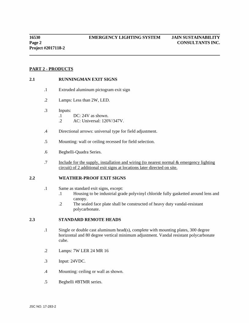
16530 EMERGENCY LIGHTING SYSTEM JAIN SUSTAINABILITY Page 2 CONSULTANTS INC. Project #2017118-2
JSC NO. 17-283-2
PART 2 - PRODUCTS 2.1 RUNNINGMAN EXIT SIGNS
.1 Extruded aluminum pictogram exit sign .2 Lamps: Less than 2W, LED. .3 Inputs:
.1 DC: 24V as shown.
.2 AC: Universal: 120V/347V. .4 Directional arrows: universal type for field adjustment. .5 Mounting: wall or ceiling recessed for field selection. .6 Beghelli-Quadra Series. .7 Include for the supply, installation and wiring (to nearest normal & emergency lighting
circuit) of 2 additional exit signs at locations later directed on site. 2.2 WEATHER-PROOF EXIT SIGNS
.1 Same as standard exit signs, except: .1 Housing to be industrial grade polyvinyl chloride fully gasketted around lens and
canopy. .2 The sealed face plate shall be constructed of heavy duty vandal-resistant
polycarbonate.
2.3 STANDARD REMOTE HEADS
.1 Single or double cast aluminum head(s), complete with mounting plates, 300 degree horizontal and 80 degree vertical minimum adjustment. Vandal resistant polycarbonate cube.
.2 Lamps: 7W LER 24 MR 16 .3 Input: 24VDC. .4 Mounting: ceiling or wall as shown. .5 Beghelli #BTMR series.
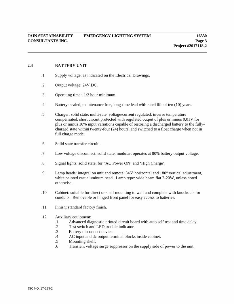
JAIN SUSTAINABILITY EMERGENCY LIGHTING SYSTEM 16530 CONSULTANTS INC. Page 3 Project #2017118-2
JSC NO. 17-283-2
2.4 BATTERY UNIT
.1 Supply voltage: as indicated on the Electrical Drawings. .2 Output voltage: 24V DC. .3 Operating time: 1/2 hour minimum. .4 Battery: sealed, maintenance free, long-time lead with rated life of ten (10) years. .5 Charger: solid state, multi-rate, voltage/current regulated, inverse temperature
compensated, short circuit protected with regulated output of plus or minus 0.01V for plus or minus 10% input variations capable of restoring a discharged battery to the fully-charged state within twenty-four (24) hours, and switched to a float charge when not in full charge mode.
.6 Solid state transfer circuit. .7 Low voltage disconnect: solid state, modular, operates at 80% battery output voltage. .8 Signal lights: solid state, for “AC Power ON’ and ‘High Charge’. .9 Lamp heads: integral on unit and remote, 345° horizontal and 180° vertical adjustment,
white painted cast aluminum head. Lamp type: wide beam flat 2-20W, unless noted otherwise.
.10 Cabinet: suitable for direct or shelf mounting to wall and complete with knockouts for
conduits. Removable or hinged front panel for easy access to batteries. .11 Finish: standard factory finish. .12 Auxiliary equipment:
.1 Advanced diagnostic printed circuit board with auto self test and time delay.
.2 Test switch and LED trouble indicator.
.3 Battery disconnect device.
.4 AC input and dc output terminal blocks inside cabinet.
.5 Mounting shelf.
.6 Transient voltage surge suppressor on the supply side of power to the unit.

16530 EMERGENCY LIGHTING SYSTEM JAIN SUSTAINABILITY Page 4 CONSULTANTS INC. Project #2017118-2
JSC NO. 17-283-2
2.5 ACCEPTABLE EMERGENCY EQUIPMENT MANUFACTURERS ARE: - Lumacell - Luxnet - Emergi-lite - Beghelli PART 3 - EXECUTION 3.1 INSTALLATION
.1 Pendant mount exit sign in service rooms and other areas where necessary to clear obstructions. Install suspended exit signs using pendants supported from swivel hangers.
.2 Install all unit equipment, remote heads, exit signs, and accessories in accordance with
manufacturer’s instruction. .3 Direct heads for illumination to meet OBC requirements.
3.2 TESTING AND VERIFICATION
.1 Arrange with the manufacturer to conduct a complete inspection and test of all installed emergency lighting system.
.2 Manufacturer’s representative shall be responsible for properly aiming remote heads,
recording the light level readings, recording battery full load operation time, issuing a verification indicating that lighting levels meet OBC requirements, and the system has been installed properly.
.3 Submit report and verification to Consultant. .4 Correct all deficiencies. .5 Witnessed by Consultant. .6 All cost involved in testing, verification, and corrections shall be included in the Base
Bid Price.
END OF SECTION