Embed Size (px)
Citation preview

OCTOBER 2007
AIR RESOURCES BOARD
STANDARD OPERATING PROCEDURE FOR THE CERTIFICATION AND VERIFICATION OF OZONE PRIMARY AND TRANSFER STANDARDS USING
THE STANDARD REFERENCE PHOTOMETER
MLD METHOD 5720
QUALITY MANAGEMENT BRANCH MONITORING AND LABORATORY DIVISION
STATE OF CALIFORNIA 1927 13th STREET
SACRAMENTO, CA 95814
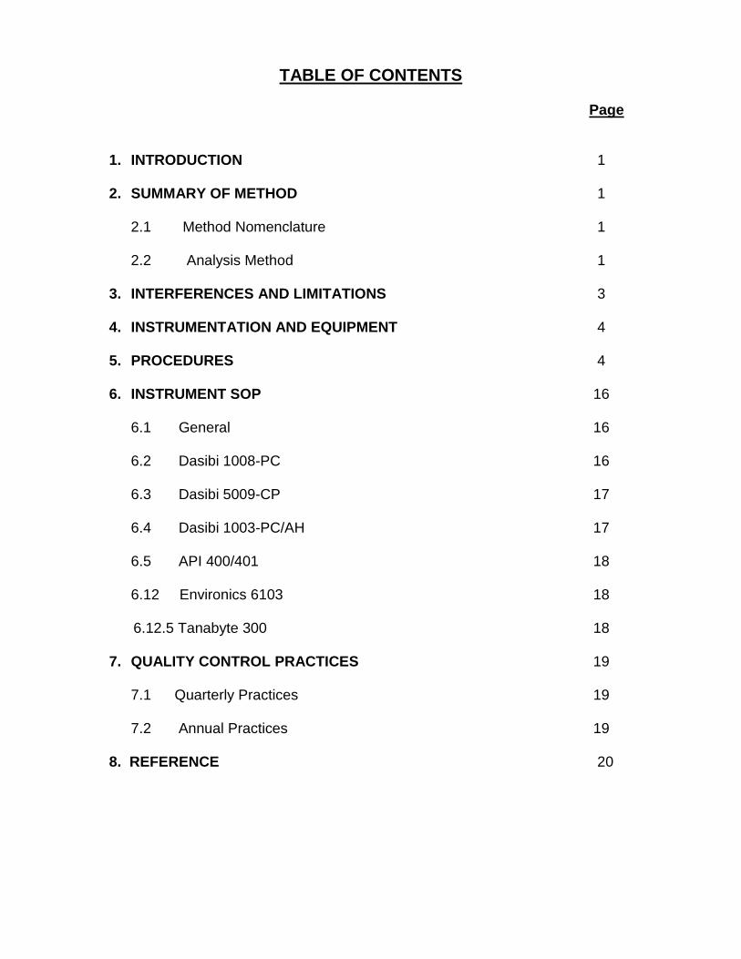
TABLE OF CONTENTS
Page 1. INTRODUCTION 1 2. SUMMARY OF METHOD 1
2.1 Method Nomenclature 1 2.2 Analysis Method 1 3. INTERFERENCES AND LIMITATIONS 3 4. INSTRUMENTATION AND EQUIPMENT 4 5. PROCEDURES 4 6. INSTRUMENT SOP 16 6.1 General 16
6.2 Dasibi 1008-PC 16 6.3 Dasibi 5009-CP 17
6.4 Dasibi 1003-PC/AH 17
6.5 API 400/401 18 6.12 Environics 6103 18 6.12.5 Tanabyte 300 18
7. QUALITY CONTROL PRACTICES 19 7.1 Quarterly Practices 19
7.2 Annual Practices 19 8. REFERENCE 20

S.O.P. MLD 5720 Effective Date: 10/18/07 Revision No: 2 Page 1 of 20 1. INTRODUCTION 1.1 This standard operating procedure describes the certification of ozone
transfer standards and verification of ozone primary standards. Ozone standards are required for the calibration and auditing of ambient ozone monitors.
1.2 This procedure uses Standard Reference Photometer (SRP) #4 to
measure ozone levels. The SRP #4 was manufactured by the National Institute of Standards and Technology (NIST). The SRP is owned by U.S. EPA; however, it is operated by the Standards Laboratory.
1.3 This procedure will determine the client’s primary or transfer standard’s
ability to accurately measure levels of ozone. The client’s instrument response is compared to the SRP’s response to levels of ozone.
2. SUMMARY OF METHOD 2.1 METHOD NOMENCLATURE 2.2 Calibration - establishes a correction factor to adjust or correct the output
of an instrument. This is determined through a comparison between an instrument and SRP at varying levels of ozone.
2.3 Certification - establishes traceability of a transfer standard to the SRP.
The certification of an instrument requires the results of six calibrations to meet requirements established by U.S. EPA.
2.4 Verification - establishes comparability of a primary standard to the SRP.
The verification of an instrument requires the results of one calibration to meet requirements established by U.S. EPA; however, the output of the instrument is not to be corrected based upon the results of the calibration.
2.5 Transfer standards – a transportable device or apparatus that is capable
of accurately producing or assaying ozone concentrations. These types of instruments undergo a certification process.
2.6 Primary standards – a device capable of assaying ozone concentrations
by UV photometry in accordance with the Code of Federal Regulations, part 50, Appendix D (40CFR50). Essentially, these types of instruments are ozone photometers that require a source of reference gas separate from sample gas (including purified sample gas). Agencies are encouraged to compare primary standards to SRPs as part of their routine quality assurance programs. These types of instruments undergo a verification process.

S.O.P. MLD 5720 Effective Date: 10/18/07 Revision No: 2 Page 2 of 20 2.7 ANALYSIS METHOD 2.8 This method of assaying ozone is based upon the tendency for it to
absorb light at a specific wavelength (254 nanometers). The amount of light absorbed is directly proportional to the amount of ozone present.
2.9 The SRP introduces a clean gas (reference gas) into the photometer and measures the amount of light (254 nanometers) through it. Then, a sample gas is introduced and the amount of light passed is measured. Based upon the previously mentioned variables, an ozone concentration can be calculated. 2.10 Schematic diagram of SRP Station.
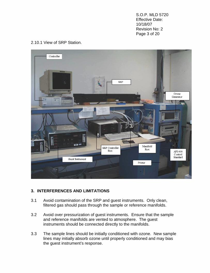
S.O.P. MLD 5720 Effective Date: 10/18/07 Revision No: 2 Page 3 of 20 2.10.1 View of SRP Station.
3. INTERFERENCES AND LIMITATIONS 3.1 Avoid contamination of the SRP and guest instruments. Only clean,
filtered gas should pass through the sample or reference manifolds. 3.2 Avoid over pressurization of guest instruments. Ensure that the sample
and reference manifolds are vented to atmosphere. The guest instruments should be connected directly to the manifolds.
3.3 The sample lines should be initially conditioned with ozone. New sample
lines may initially absorb ozone until properly conditioned and may bias the guest instrument’s response.

S.O.P. MLD 5720 Effective Date: 10/18/07 Revision No: 2 Page 4 of 20 3.4 Allow guest instrument to warm-up for a minimum of 2 hours. 3.5 Allow guest instrument and SRP to stabilize at each ozone concentration
level for a minimum of 20 minutes. 3.6 Ensure the flow from the Environics 9100 is greater than the sample flow
rate of the guest instruments and SRP (5 lpm). 4. INSTRUMENTATION AND EQUIPMENT 4.1 SRP and support equipment. 4.2 Environics 9100 calibrator, ozone source. 4.3 Computer and monitor, with associated software. 4.4 Ultra pure grade air. 4.5 Teflon gas lines. 4.6 High accuracy barometer, for ambient pressure reading. 4.7 High accuracy thermometer, for ambient temperature reading. 5. PROCEDURES 5.1 Turn on guest instrument. Allow it to warm up for a minimum of 2 hours. 5.2 Connect sample line “O3A” or “O3B” to sample inlet port on back of
instrument. 5.3 If instrument is a primary standard photometer, connect reference gas line
“ZEROA” or “ZEROB” to reference leg of sample solenoid inside instrument. Some instruments require pressurized reference gas, use Teflon line labeled “PRESS AIR”.
5.4 Obtain ambient pressure using the Barometer SOP. 5.5 Perform Instrument SOP; see section 6 for specific instrument model. 5.6 Turn power switch on Environics 9100 to “ON” position. 5.7 Turn on the black zero air toggle valve at back of the Environics 9100. (Up
is the “OPEN” position).

S.O.P. MLD 5720 Effective Date: 10/18/07 Revision No: 2 Page 5 of 20 5.8 Set the house air regulator supplying air to the Environics 9100 to 35 psi. 5.9 On the Environics 9100, select the “Flow Mode” from the menu screen. Enter “0.0” for the flow rate of mass flow controller (MFC) #1, “13.0” for MFC #2, and “0.0” for ozone concentration. Then, select “Update” on menu screen. 5.10 Set the service air regulator to 20 PSI on the Environics 9100 calibrator rack. 5.10.1 Left click on SRP Control on the computer desktop. Click on
System, then Diagnostics, Stability Monitor.
5.10.2 To start the Stability monitor, click SRP 4 and Print Status Report
Window as illustrated. After 20 complete cycles, the desktop will look like the following illustration. StdDev should be less than 25 for Scaler 1 and Scaler 2. Scaler 1 and Scaler 2 should be greater than 90,000.

S.O.P. MLD 5720 Effective Date: 10/18/07 Revision No: 2 Page 6 of 20 5.10.3 At the conclusion of the Stability monitor test the printer will output a
hard copy of the results as shown below. As well as ensuring that the StdDev of both scalers is less than 25, transpose the temperature, pressure and Scaler 1 and 2 onto the SRP section of form ozone 2007, illustrated in section 5.13.

S.O.P. MLD 5720 Effective Date: 10/18/07 Revision No: 2 Page 7 of 20 5.10.4 Diagnostic Test Report, printed at the conclusion of the diagnostic test run.

S.O.P. MLD 5720 Effective Date: 10/18/07 Revision No: 2 Page 8 of 20 5.10.5 To configure the instrument under test, click on Edit then Configurations to reveal the following screen.
5.10.6 Type in the test instrument make. 5.10.7 Type in the instrument model. 5.10.8 Type in the CARB instrument serial #. 5.10.9 Type in the instrument owner. 5.10.10 Type in the instrument contact.

S.O.P. MLD 5720 Effective Date: 10/18/07 Revision No: 2 Page 9 of 20 5.11 Left click the Instrument Active box. 5.11.1 Click None for Connection Mode. 5.11.2 Click Data entered during acquire box. 5.11.3 Left click on save configuration. 5.11.4 Click on System, Calibration,Standard. 5.11.5 Calibration Information and Setup screen.
5.11.6 Type in operators name in Operator box.

S.O.P. MLD 5720 Effective Date: 10/18/07 Revision No: 2 Page 10 of 20 5.11.7 Ensure Air flow rate is 5.0, Lamp percent Range: Low is 0.0, High is
50.0, Lamp percent conditioning is 30.0, time(min) is 0, Number of Conc. Points is 7, Points/Conc. 10, number of Cycles is 1.
5.11.8 Ensure steps 1 through 7 are selected, Generator % is arbitrary as
Environics 9100 is used for ozone generation rather than the SRP internal ozone generator.
5.11.9 Order High to Low Conc. Dark Count 4, Auto Print Excel Report,
Guest #1 boxes are active. If a second instrument is being assayed Guest #2 should also be active.
5.11.10 Excel Report Template should be selected as SRPTemplate.xl 5.12 Simple.mth should be selected in Link Method box. 5.12.1 Click on Save conditions.
5.12.2 In the File name area, type the date, i.e. 70711a would indicate the
year 2007 (7), the month (07) and the day (11). a indicates the first assay of the day, b would indicate the second, c the third etc.
5.12.3 Click Save.

S.O.P. MLD 5720 Effective Date: 10/18/07 Revision No: 2 Page 11 of 20 5.12.4 Calibration Information and Setup screen will be displayed again. Click on OK to start the assay.
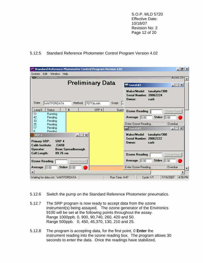
S.O.P. MLD 5720 Effective Date: 10/18/07 Revision No: 2 Page 12 of 20 5.12.5 Standard Reference Photometer Control Program Version 4.02
5.12.6 Switch the pump on the Standard Reference Photometer pneumatics. 5.12.7 The SRP program is now ready to accept data from the ozone instrument(s) being assayed. The ozone generator of the Environics 9100 will be set at the following points throughout the assay. Range 1000ppb. 0, 900, 90,740, 260, 420 and 50. Range 500ppb. 0, 450, 45,370, 130, 210 and 25. 5.12.8 The program is accepting data, for the first point, 0 Enter the instrument reading into the ozone reading box. The program allows 30 seconds to enter the data. Once the readings have stabilized,

S.O.P. MLD 5720 Effective Date: 10/18/07 Revision No: 2 Page 13 of 20 indicated by a Stdev of less than 1 of both the SRP reading and the instrument being assayed, the red indicators will turn green. At this point the program will indicate actual data. After ten entries the status column will indicate complete and the Enter ozone reading will indicate done. Repeat this process for the other 6 ozone concentrations. After completion of the data the following results will be printed. 5.12.9 Standard Reference Photometer Calibration Report
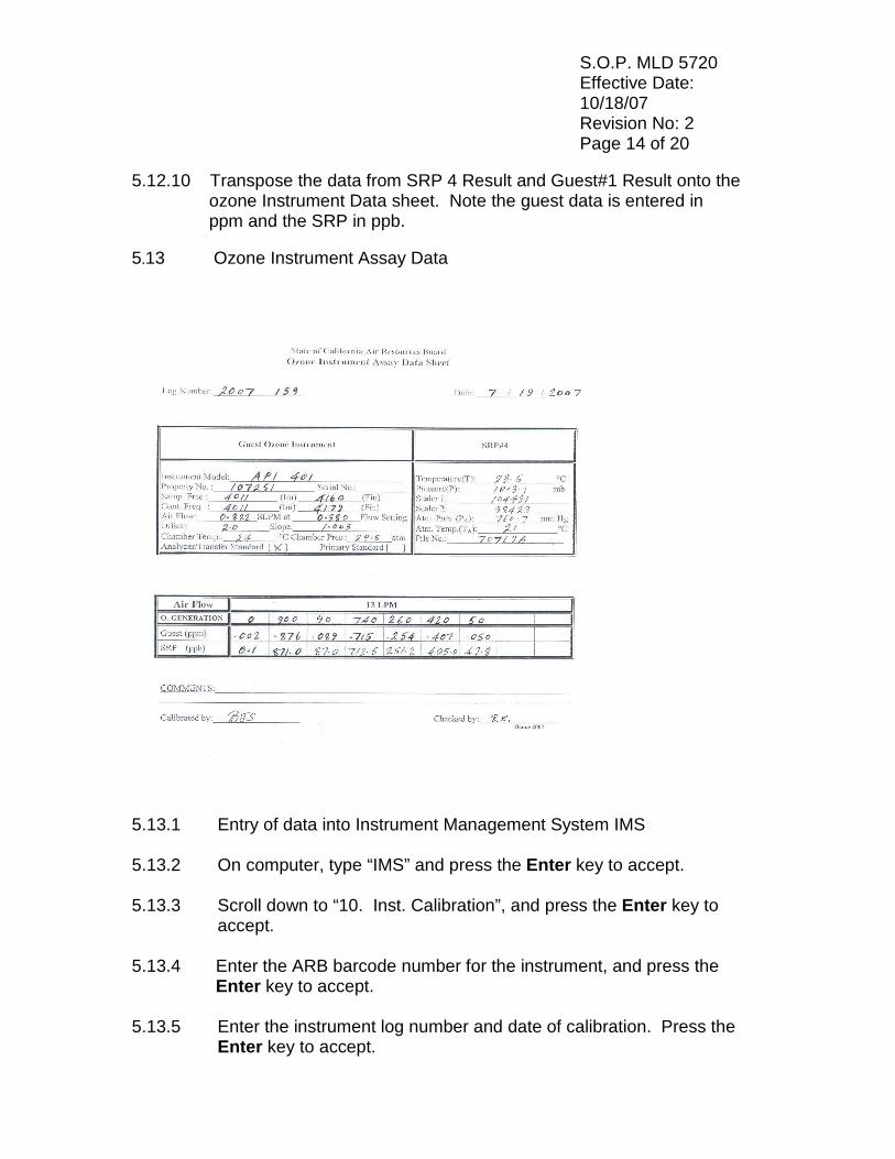
S.O.P. MLD 5720 Effective Date: 10/18/07 Revision No: 2 Page 14 of 20 5.12.10 Transpose the data from SRP 4 Result and Guest#1 Result onto the ozone Instrument Data sheet. Note the guest data is entered in ppm and the SRP in ppb. 5.13 Ozone Instrument Assay Data
5.13.1 Entry of data into Instrument Management System IMS 5.13.2 On computer, type “IMS” and press the Enter key to accept. 5.13.3 Scroll down to “10. Inst. Calibration”, and press the Enter key to
accept. 5.13.4 Enter the ARB barcode number for the instrument, and press the
Enter key to accept. 5.13.5 Enter the instrument log number and date of calibration. Press the
Enter key to accept.
S.O.P. MLD 5720 Effective Date: 10/18/07 Revision No: 2 Page 15 of 20 5.13.6 Enter “Y” if performed an instrument calibration, or “N” if other.
Press the Enter key to accept. 5.13.7 The computer will display several datapoints. If the datapoints are
correct, enter “Y”, or enter “N” to edit the datapoints. Press the Enter key to accept.
5.13.8 If enter “N”, edit values to match those targeted during the
calibration. Enter “Y” after completing edits. Press the Enter key to accept.
5.13.9 Enter initial and final sample and control frequency values from test
data sheet. Enter instrument temperature and pressure values. Enter SRP Scaler 1, Scaler 2, Pressure, and temperature values. Enter ambient pressure and temperature values from test data sheet. Press the Enter key to accept.
5.13.10 Enter “A” if instrument is a transfer standard or “P” if a primary
standard photometer. Press the Enter key to accept. 5.14 Enter instrument response from on the test data sheet (entered in
ppm) and the SRP response (entered in ppb). Press “Y” after all data entered correctly, or “N” to edit data. Press the Enter key to accept.
5.14.1 Print calibration data by selecting the first option. Press the Enter
key to accept. Press shift and continue on printer when pompted to print results.
5.14.2 Print the certification results by selecting the second option. Press
the Enter key to accept. If instrument results meets the certification criteria, press shift and continue on the printer when prompted to print.
5.14.3 If instrument results does not meet the certification criteria, enter
“Y” or “N” to print certification results. Press the Enter key to accept, and press the shift and continue on the printer when prompted.
5.14.4 Print the instrument report by selecting the third option. Press the
Enter key to accept, and press shift and continue on the printer when prompted.

S.O.P. MLD 5720 Effective Date: 10/18/07 Revision No: 2 Page 16 of 20 5.14.5 Press the Esc key twice, and quit the Instrument Management
System by selecting the last option. Press the Enter key to accept. 5.15.6 At the Dos prompt, type “Exit” and press the Enter key to accept. 5.15.7 On SRP control box, turn off pump. 5.15.8 If instrument certification or verification is complete, denenergize
instrument. Disconnect power cable and sample lines. Cap the ends of the sample lines to prevent contamination.
6 INSTRUMENT UNDER TEST SOP 6.1 General 6.2 The following instrument SOPs are the most common models operated by the Standards Laboratory. For instruments not covered by the following SOPs, refer to the instrument’s operation manual to obtain the following data: sample frequency, control frequency, sample temperature, sample pressure, and sample flow setting. Use a Vol-O-Flow meter to obtain actual sample flow rate. 6.3 DASIBI 1008-PC 6.4 Place the Mode selector switch to the Sample/Temp position. With
the T/P switch in the On position, record the instrument’s chamber temperature on the test data sheet.
6.5 Place the T/P switch in the Off position, record the instrument’s
sample frequency on the test data sheet. 6.6 Place the Mode selector switch to the Control/Press position.
Record the instrument’s control frequency on the test data sheet. 6.7 Place the T/P switch in the On position, record the instrument’s pressure on the test data sheet. 6.8 Place the Mode selector switch to the Operate position. 6.9 Remove the instrument’s cover panel, record the three SPAN thumbwheel settings on test data sheet. 6.10 Record the instrument’s ZERO thumbwheel setting on the test data sheet.

S.O.P. MLD 5720 Effective Date: 10/18/07 Revision No: 2 Page 17 of 20 6.10.1 Replace the instrument’s cover panel. 6.10.2 Using a Vol-o-Flow flow meter, measure and record the instruments sample flow rate on the test data sheet. Also record the flow rate setting on the instrument’s rotameter. 6.10.3 DASIBI 5009-CP 6.10.4 Record the instrument’s Span and Offset settings from
thumbwheels on front panel onto the test data sheet. 6.10.5 Using the DIAG. thumbwheel, select diagnostics “3”. Record the
temperature and pressure readings on the test data sheet. 6.10.6 Using the DIAG. Thumbwheel, select diagnostics “5”. Record the
sample and control frequencies onto the test data sheet. The top value is the sample frequency, and the bottom value is the control frequency.
6.10.7 Return the DIAG. thumbwheel to “0”. 6.10.8 Using a Vol-o-Flow flow meter, measure and record the
instrument’s sample flow rate on the test data sheet. Also record the flow rate measure on the instrument’s rotameter.
6.10.9 DASIBI 1003-PC/AH 6.10.10 Record instrument Span and Offset settings from dials on front
panel onto the test data sheet. 6.11 sing the mode selector switch, select the Sample setting. Allow
unit to update the display several times and record value on the test data sheet.
6.11.1 Using the mode selector switch, select the Cont. setting. Allow unit
to update the display several times and record value on the test data sheet.
6.11.2 Return the mode selector switch to Operate. 6.11.3 Using a Vol-o-Flow flow meter, measure and record the
instrument’s sample flow rate on the test data sheet. Also record the flow rate measure on the instrument’s rotameter.
S.O.P. MLD 5720 Effective Date: 10/18/07 Revision No: 2 Page 18 of 20 6.11.4 API 400/401 6.11.5 Using the TST> key, toggle until “Press = XX.X In-Hg-A” is displayed, record value as instrument’s pressure reading on test data sheet. 6.11.6 Press the TST> key once, record value as instrument’s flow setting
on test data sheet. 6.11.7 Press the TST> key once, record value as instrument’s temperature
reading on the test data sheet. 6.11.8 Press the TST> key until the instrument’s slope value is displayed.
Record value as instrument’s span setting on test data sheet. 6.11.9 Press the TST> key once, record the displayed value as
instrument’s offset setting on test data sheet. 6.11.10 Using a Vol-o-Flow flow meter, measure and record the instruments
sample flow rate on the test data sheet. 6.12 ENVIRONICS 6103 6.12.1 Press F3 under Photo display, press F2 under detail. 6.12.2 Record photometer frequencies xxxxxx/xxxxxx, pressure P,
temperature T and flow F. 6.12.3 To record offset, press Exit, Conc, Flow, Photo will be displayed.
Press Menu twice; press the F1 key under system. 6.12.4 Use the down key to scroll to calibrate photo. Press enter key,
record offset and gain values, press accept. Press exit, then menu, press photo then detail. Instrument is now ready to assay.
6.12.5 TANABYTE 300 6.12.6 Screen displays O3 Prs ,Phot Temp, record these parameters on
form ozone 2007. 6.12.7 Press Esc, then 2, Control, then 3, Manual control. From the
manual control menu, press 2 for flows and then Enter. Press 4 for air flow (LPM), and then Enter. For gas flows, press 0, and then Enter. Are you sure? Will be displayed. Press up arrow, and then Enter to accept. Manual flow will now start.

S.O.P. MLD 5720 Effective Date: 10/18/07 Revision No: 2 Page 19 of 20 6.12.8 On manual control menu press 3 for ozone intensity, enter 0 for
intensity % Enter. Are you sure? Will be displayed, press up arrow key, Ent to accept. Press Esc for the main menu.
6.12.9 From main menu press 4: Test, from test menu press 2: view
parameters. From view parameters press 5: Photometer. From view photometer press 2: Photo Cal. Record slope and intercept. Press Ent. To exit. Record Det I and Det I0 as frequencies on form ozone 2007. The instrument is now ready to assay.
7 QUALITY CONTROL PRACTICES 7.1 QUARTERLY PRACTICES 7.2 An Advanced Pollution Instruments, model 400 (ARB barcode
#20004767), is used as a control standard. This instrument is compared to the SRP on a quarterly basis. A control chart is derived from historical comparisons. From the control chart, warning and out of control limits are defined.
7.3 For warning limit violations, investigations are initiated into the
quality of house air, parameters associated with the SRP. 7.4 For out of control limit violations, no instrument comparisons are allowed until the cause is found. Perform all the checks associated with a warning limit violation. If no cause is revealed, a request for a comparison with another SRP should be made to U.S. EPA; No further instrument comparisons should be made until the results of the SRP comparison is analyzed. 7.5 ANNUAL PRACTICES 7.6 A second SRP (SRP #7) is used to verify the proper operation of the SRP. Originally, U.S. EPA was performing this verification annually. However, the SRP’s historical accuracy and stability has allowed it to be verified on a biennial basis. U.S. EPA ships SRP #7 and the Standards Laboratory perform the comparison. The Standards Laboratory strictly follows Section 9.0 of Reference 9.2 during the performance of the verification.

S.O.P. MLD 5720 Effective Date: 10/18/07 Revision No: 2 Page 20 of 20 8 REFERENCES 8.1 Transfer Standards for Calibration of Air Monitoring Analyzers for Ozone. Technical Assistance Document, EPA-600/4-79-056 September 1979, U.S. Environmental Protection Agency, Research Triangle Park, North Carolina.


![STANDARD OPERATING PROCEDURE [SOP] · STANDARD OPERATING PROCEDURE [SOP] ... [CDSCO] with registration no. ECR/ 331/ Inst/ GJ/ 2013/ RR-16, ... ratio, Distribution of](https://img.pdfslide.net/doc/110x75/5b14dc057f8b9a54488c8541/standard-operating-procedure-sop-standard-operating-procedure-sop-cdsco.jpg)