Embed Size (px)
Citation preview

Sound Devices for the Cricket Bus System
by
Genee Lyn 0. Colobong
Submitted to the Department of Electrical Engineering and Computer Sciencein Partial Fulfillment of the Requirements for the Degrees of
Bachelor of Science in Electrical Science and Engineering
and Master of Engineering in Electrical Engineering and Computer Science
at the Massachusetts Institute of Technology
June 4, 1999
@ Copyright 1999 Genee Lyn 0. Colobong. All rights reserved.
The author hereby grants to MIT permission to reproduce anddistribute publicly paper and electronic copies of this thesis
and to grant others the right to do so.
A uthor ........ .. ... ....................I~epartment of Electrical Enginee and Computer Science
May 21, 1999
Certified by ...... ..... ..................................Fred G. Martin
Research S ist, MIT Media Lab
Accepted by ......................... .. . ..
Arthur C. SmithChairman, Department Committee on Graduate Theses
MASSACHUSETTS INSTITUTEOF TECHNOL
L RIES

Sound Devices for the Cricket Bus System
by
Genee Lyn 0. Colobong
Submitted to the Department of Electrical Engineering and Computer Scienceon May 21, 1999, in partial fulfillment of the
requirements for the Degrees ofBachelor of Science in Electrical Science and Engineering
and Master of Engineering in Electrical Engineering and Computer Science
Abstract
The Cricket is the latest technology in behavior construction kits developed by the Episte-mology and Learning Group of the MIT Media Laboratory. It is a tiny computer, the sizeof a 9-volt battery, that is capable of handling two sensors, two motors and other sensorsand actuators through the Cricket Bus System. In this thesis, I designed, prototyped andproduced the Sound Sensor and the Voice Recorder, two sound devices for this system.The Sound Sensor is a two-in-one clap sensor and volume sensor. The Voice Recorder is arecord and playback device that can be controlled through a user pushbutton interface andthrough Cricket Logo, the programming tool the group developed for the Crickets. Thethesis also includes the field testing at a workshop I held in which children built Cricketprojects that used some of these sound devices.
Thesis Supervisor: Fred G. MartinTitle: Research Scientist, MIT Media Lab
2

Acknowledgments
I would like to thank God for allowing me to glorify Him by finishing this thesis, and for
giving me His peace and strength through it. I would also like to thank my family, especially
my father, who has always supported me and believed in me.
This thesis would not have been possible without my co-advisors, Fred Martin and
Mitchel Resnick, who have given me so much guidance and encouragement throughout this
year.
My thanks go to my fianc6, Ely Wilson, for his support and understanding, and to my
best friend, Irene Wilson, for believing that I could finish this thesis even before I began
believing it myself.
I would like to thank all of my friends who have been praying for me steadily from the
very beginning: the Ashdown Monday night Bible Study, my Campus Crusade womens'
group, and especially my dearest friends, Elissa Lee and Louisa Chiu.
I give thanks to my friends from the Epistemology and Learning group, especially
Bakhtiar Mikhak, Michelle Shook, Tim McNerney, Clint Sieunarine, and Chris Hancock,
without whose help, I would not have managed through the workshop.
3

Contents
1 Introduction
1.1 Constructionism . . .
1.2 Prior Work . . . . . .
1.2.1 LEGO/Logo .
1.2.2 Programmable
1.2.3 Crickets . . .
1.2.4 Cricket Bus .
1.3 Goals of this Research
Brick
2 The Sound Sensor
2.1 How the Sound Sensor Works . . . . .
2.2 How the Sound Sensor is Used . . . . .
2.3 Hardware . . . . . . . . . . . . . . .
2.4 Software . . . . . . . . . . . . . . . .
2.4.1 The Clap and Volume Functions
2.4.2 The Bus Protocol . . . . . . .
2.4.3 Cricket Logo Macros . . . . .
3 The
3.1
3.2
3.3
Voice Recorder
How the Voice Recorder Works . . . .
How the Voice Recorder is Used . . . .
Hardware . . . . . . . . . . . . . . .
3.3.1 Voltage Regulator Circuit . . .
4
8
8
9
9
9
10
12
13
15
15
17
18
21
21
24
26
28
28
30
31
33
. ..... ... ..
..... .... ..
.... .... ...
... ..... ...
... .... ....

3.3.2 Microprocessor Circuit . . . .
3.3.3 Record/Playback Chip Circuit .
3.3.4 Audio Amplifier Circuit . . . .
3.4 Software . . . . . . . . . . . . . . . .
3.4.1 The Main Loop and Button/Bus
3.4.2 The Record Sequence.....
3.4.3 The Playback Sequence . . . .
3.4.4 The Fast-Forwarding Sequence
Handling
4 Field Test: The Community Arts Center Workshop
4.1 Day by Day Narrative . . . . . . . . . . . . . . . . . . . . . . . .
4.2 Technology Evaluation . . . . . . . . . . . . . . . . . . . . . . . .
4.3 Some Comments on Workshop-Based Learning . . . . . . . . . . .
5 Future Directions
5.1 Future Sound Sensors . . . . . . . . . . . . . . . . . . . . . . . .
5.2 Future Voice Recorders . . . . . . . . . . . . . . . . . . . . . . .
5.3 Ideas for Future Sound Bus Devices . . . . . . . . . . . . . . . . .
A Sound Sensor Assembly Language Program
B Voice Recorder Assembly Language Program
C Cricket Logo Macros for the Sound Sensor and Voice Recorder
5
34
35
36
38
38
39
41
44
46
47
53
56
58
58
59
60
62
67
76

The Sound Sensor . . . . . . . . . . . . . . . . . . . . . . .
Sound Sensor Circuit Schematic . . . . . . . . . . . . . . . .
Sound Sensor Printed Circuit Board Layout: Component Side
Sound Sensor Printed Circuit Board Layout: Solder Side . . .
Sound Sensor Flowchart . . . . . . . . . . . . . . . . . . . .
Bus Protocol Flowchart . . . . . . . . . . . . . . . . . . . .
The Voice Recorder . . . . . . . . . . . . .
Voice Recorder Circuit Schematic . . . . . .
Voice Recorder Printed Circuit Board Layout:
Voice Recorder Printed Circuit Board Layout:
The Record Sequence State Diagram . . . .
The Playback Sequence State Diagram . . .
The Fast-Forwarding Sequence State Diagram
. . . . . . . . . .
Component Side .
Solder Side . . .
4-1 Mary's Dancing Car . . . . . . . . . . . . . . . . . . . . . . .
4-2 Steve's Plane . . . . . . . . . . . . . . . . . . . . . . . . . . .
6
List of Figures
2-1
2-2
2-3
2-4
2-5
2-6
3-1
3-2
3-3
3-4
3-5
3-6
3-7
. . . . . 16
. . . . . 19
. . . . . 20
. . . . . 21
. . . . . 22
. . . . . 25
. . . . . 29
. . . . . 32
. . . . . 33
. . . . . 34
. . . . . 40
. . . . . 42
. . . . . 44
52
54

List of Tables
2.1 Sound Sensor Parts Listing. . . . . . . . . . . . . . . . . . . . . . . . . 23
3.1 Voice Recorder Parts Listing . . . . . . . . . . . . . . . . . . . . . . . . 37
7

Chapter 1
Introduction
Constructionism is the belief that children learn most effectively when they are engaged in
design, construction and debugging activities. In the spirit of constructionism, the Episte-
mology and Learning Group of the MIT Media Lab has created the Crickets, an educational
technology that allows children to create mechanisms, creatures, and scientific instruments
while exploring a variety of concepts including sensing, control and systems. Crickets are
fully-programmable computational devices that can control motors and displays, receive
information from sensors, and communicate with one another via infrared light. For this
thesis, I developed sound input and output devices for the Crickets to widen the range of
possibilities that Crickets can be used in children's projects.
1.1 Constructionism
One of the themes in the research of the Epistemology and Learning Group is learning
through design. The group believes that learning does not just happen by transmitting
knowledge from the teacher to the student, but through an active construction of knowledge
in the mind of the student[10]. This theory of learning is called constructionism: "the idea
that people construct new knowledge with particular effectiveness when they are engaged
in constructing personally-meaningful products"[12], one that they can reflect upon and
share with others. The group's research is developing new technologies that aid children in
designing their own artifacts.
8

1.2 Prior Work
The construction kit would come to mind as a technology that would support children as
designers. One role that the Epistemology and Learning Group sees for itself is to extend
this basic construction kit and to develop new generations of construction kits. One can
see the original LEGO system as a first-generation construction kit allowing children to
build structures. The second-generation kits allow children to build mechanisms with the
aid of gears, axles, motors and battery packs, new parts that come in LEGO's Technic set.
The third-generation construction kits allow children to build behaviors[ 11]. With LEGO's
new Mindstorms set, children can program behaviors into their mechanisms using its own
programmable computer. This set is the product of the group's research and collaboration
with the LEGO company.
1.2.1 LEGO/Logo
The group's research on behavior construction kits began with a project called LEGO/Logo,
developed primarily by Mitchel Resnick, Stephen Ocko, Brian Silverman, and Seymour
Papert[ I11]. With LEGO/Logo, children build machines out of LEGO bricks and LEGO
gears, motors, and sensors, then write computer programs, using a modified version of
Logo, to control the machines. The LEGO company developed a commercial version of
LEGO/Logo called "LEGO tc Logo."
The LEGO/Logo project has one big limitation: It has to be connected to a desk-
top computer. Children can build mobile creatures that can only go as far as the wire
connections will let them. The wires can also get tangled and twisted with rotating ma-
chines and creatures[14]. This problem led the group to develop the next technology: the
Programmable Brick.
1.2.2 Programmable Brick
The Programmable Brick solves the problem by putting the computer into a LEGO brick.
The Programmable Brick[5], developed primarily by Fred Martin, is about the size of a
child's juice box. Run by the Motorola 68HC1 1 processor and 32 kilobytes of RAM, it is
9

capable of controlling up to four motors, and receiving input from up to six sensors. The
Brick can communicate by infrared light, and it can display information on its two-line
liquid-crystal display. It also includes a knob and two buttons for interacting directly with
the Brick.
Children still build their own machines and creatures using LEGO bricks, gears, motors,
and sensors, and they still write their programs (using a modified version of Logo called
Brick Logo) on a desktop computer, but the programs they write are downloaded to the
Programmable Brick, using a detachable cable, and then the Brick can be taken wherever
they want. The kids can then add the Programmable Brick to their LEGO machine/creature,
connect the motors and sensors, scroll through the downloaded programs with the knob,
press the start button and watch their creation come to life[6].
The LEGO company just recently released its commercial version of the Programmable
Brick, called the RCX Brick, which they include in the LEGO Mindstorms set.
1.2.3 Crickets
The latest technology developed by the Epistemology and Learning Group after the Pro-
grammable Brick are the Crickets. Crickets, which are roughly the size of a 9-volt battery,
are much smaller and lighter than the Programmable Brick. They are capable of controlling
fewer motors and sensors, but they are able to communicate to each other through infrared
communications. The latest version of the Crickets allow them to control a number of
input and output devices by daisy-chaining them to the Crickets. They are programmed
in Cricket Logo, and the programs are downloaded to the Cricket by infrared through an
Interface Cricket[3].
There are three versions of the Crickets so far: The Green Dot, Red Dot and Blue Dot.
The three versions of the Classic Cricket have the same standard components: [2]
* Microchip's PIC microprocessor
* 4 MHz ceramic resonator
* EEPROM memory
10

* infrared transmitter and receiver
" two motor outputs with bi-colored LEDs to indicate the state
" two sensor inputs for resistive devices
* Piezo beeper
e on/off slide switch
* user pushbutton switch
" three LEDs indicating power-on, program running and infrared transmission inprogress
" 9-volt battery source
The original Green Dot Cricket family consisted of the Classic Cricket (also known as
the Sensor/Motor Cricket), the Display Cricket and interface crickets for Mac and PC, all
using Microchip's PIC 16C84 microprocessor. The Red Dot Classic Cricket was developed
with the PIC 1 6F84 microprocessor which has all the capabilities of the C84 but with flash
memory and double the size of data RAM, allowing the user's Cricket Logo programs to be
larger and more complex. The motor outputs were also enhanced, now able to source 1000
mA of current instead of the 150 mA in the Green Dot version.
The Blue Dot Classic Cricket uses the PIC16C715 microprocessor, allowing 16-bit
numbers, and a new infrared transmitter and receiver, for faster communication and less
noise sensitivity.
The Macintosh and PC interface crickets are equipped with a Macintosh or PC serial
connector and IR transmitters and receivers, and they transform the serial data from the
serial port of the desktop computer to an infrared signal, which can be received by the
Classic Crickets. The interface crickets did not undergo any changes until the Blue Dot
version. The IR transmitter and receiver were replaced and a DC power jack was added to
allow a DC adapter to supply the power.
The Green Dot Display Cricket has a row of 8 bi-colored LEDs as a bargraph display
along with three sensor inputs, but no newer versions were made because the Classic Cricket
was found to be the only one needed. The specialization of Crickets became unnecessary
with the development of the Cricket Bus System.
11

1.2.4 Cricket Bus
One of the most significant additions to the Blue Dot Crickets is the Cricket Bus System.
Two Cricket bus ports with 9 volts, ground and a serial bus line allow the Blue Dot Crickets
to have a wider range of input and output capabilities, instead of just the two sensors and
two motor ports that are present in the previous versions. The Cricket bus devices are more
complex than the usual sensor or motor that are connected to the sensor and motor ports.
Each bus device has a microcontroller to communicate with the Blue Dot Classic
Cricket microcontroller via the serial bus line. It also has its own voltage regulator circuitry
to convert the global 9 volts from the Cricket bus, supplied by the Blue Dot Cricket's 9-volt
battery, to its local 5 volts. Each bus device also includes two Cricket bus ports: one to
connect to the Cricket bus network which has the Blue Dot Cricket at its center, and the
other to allow more bus devices to be part of the network. The only limit to the number of
Cricket bus devices that can communicate to the Blue Dot Cricket is the power required to
supply each of the bus devices and the signal degradation of the serial bus line due to the
capacitive loading of enough bus devices.
Cricket bus devices greatly extend the input and output capabilities of the Blue Dot
Classic Cricket. Several devices that have already been developed are:
3-Digit-Display is a 3-digit 7-segment LED display usually used to display sensor read-
ings, but can also be reprogrammed to display some alphanumeric characters.
Bar Graph Display replicates the functionality of the Green Dot Display Cricket.
Distance Sensor uses the same technology as those found in bathrooms, where the sink
can determine whether the faucet should turn on or not if it "sees" hands underneath
the faucet, and the toilet can determine whether to flush or not if it senses a person in
the stall.
Reflectance Sensor outputs a value corresponding to the reflectivity of the object it is
pointing to; it can be very useful, for example, to a LEGO car that follows a black
tape on a white surface.
12

Heart Monitor is capable of counting the user's heart beats and calculating the heart rate,
using a commercial heart monitor worn around the user's chest.
Galvanic Skin Response (GSR) Sensor can be used somewhat like a lie detector by
measuring the amount of sweat that the skin produces as questions are asked over a
period of time.
MIDI device allows songs to be programmed into the Blue Dot Cricket which can then be
played through the MIDI device.
1.3 Goals of this Research
The purpose of this thesis is to augment the Cricket Bus System by developing Cricket bus
devices that are related to sound. With the exception of the MIDI device, none of the other
bus devices mentioned above deal with sound, making sound an under-explored area. I
believe that enhancing the sound capabilities of the Cricket System can expand the range
of activities that the children can use the Crickets with. One such activity that the sound
devices (as well as the already existing bus devices) can play a role in is the building of
scientific instruments, a charter of the Beyond Black Boxes project.
The Beyond Black Boxes project[13], funded by the National Science Foundation, is
a project that the Epistemology and Learning Group began that aims to open up the black
boxes of science to children by allowing them to make scientific investigations in their own
worlds, design their own experiments, and build their own scientific instruments for these
experiments. By involving the children in building their personalized scientific instruments,
the group expects them to be able to engage in more meaningful and motivating science-
inquiry activities. The Cricket technology is central in the designing of the children's
scientific instruments. Kids can use the Crickets with all kinds of sensors to gather data for
their experiments, including the bus device sensors mentioned above that were developed
strictly for this project:
For example, one group of students might use Crickets to build an "activehamster cage" that monitors and responds to the activity of a pet hamster. An-other group might create a "wearable instrument" that analyzes the relationship
13

between a person's heartbeat and their level of exertion throughout a day. Otherstudents might build an autonomous submarine, equipped with a Cricket andsensors, to investigate pollution levels at different depths and locations in anearby lake or harbor[13].
My research contributes to the Beyond Black Boxes project with the development
of sound-related Cricket bus devices that kids can use in their scientific experiments. For
example, a volume sensor on a Cricket can be used to measure the amount of noise pollution
that a person might be exposed to throughout the day. A child might place a Cricket with a
voice recorder on a tree branch and program the Cricket to begin recording when it senses
that a bird is present to record the chirps that it makes.
For this thesis, I designed, prototyped and produced two devices: a two-in-one sound
sensor, that functions as a clap sensor and a volume sensor, and a voice recorder. I have
also held a workshop with kids where they built projects using the Crickets and some of
these devices.
The following chapters discuss more in detail the technical development of the two
devices. Chapter 2 discusses the development of the sound sensor, and Chapter 3 focuses
on the voice recorder. Chapter 4 of this thesis talks about the 5-day workshop that I held
at the Community Arts Center, where the children built Cricket projects that use the sound
sensor and voice recorder. The last chapter, Chapter 5, discusses the future work that could
be done for the two devices and other devices for the Cricket Bus System.
14
Chapter 2
The Sound Sensor
The purpose of the sound sensor is simply to sense sounds. But since there are always
sounds in the environment, it is important to distinguish between background noise and the
specific sounds that the user wants to focus on. Volume is the key factor that differentiates
these foreground sounds from the background sounds. Frequency is another quality of
sound that can be easily differentiated. The clap and volume functions use volume to
trigger the sensor, while the tone recognition function relies on the frequency of the input
sound.
2.1 How the Sound Sensor Works
The easily distinguishable difference in volume between a clap and other sounds is the
reason why the first implementation of the sound sensor is the clap-sensing function.
Claps are easily distinguishable by the high-amplitude impulse-like sound waves that they
produce. When the microphone hears a clap, or any other sound, a voltage signal in the
form of a broad impulse is generated. The signal is amplified by the microphone amplifier
circuit, and is then converted to a digital byte, using the analog-to-digital converter pin on
the microprocessor. The microprocessor has a threshold set where it registers a clap if the
value of the byte is above this threshold. In software, the value is exponentially decayed
if the microphone does not pick up any other sound within a small period of time. The
microprocessor then sends a binary 255 or 0 to the Cricket Bus whenever the Blue Dot
15

Figure 2-1: The Sound Sensor
Classic Cricket asks for this sensor input.
The second function, the volume-sensing, can be derived from the integral part of the
clap-sensing function. The same process is used except the output is the digital byte given
by the A/D converter. There is no need to compare the value to a threshold. It is simply
passed along through the bus as a value ranging from 0 to 255 to the Blue Dot Cricket
whenever this sensor input is asked for.
Another quality of sound that can be easily differentiated is frequency or tone. A tone
recognition sensor can be implemented by a crude Fourier transform done in software with
the input signal and a set frequency. If the input frequency is about half a tone away from the
set frequency, the microprocessor registers it as a match. Ava Erickson, an undergraduate
student at Wellesley College successfully prototyped one of these. Unfortunately, her code
is written so that the device only responds to one tone, 1200 Hertz, a pitch that she can
naturally whistle. The whistle is important since it is a naturally-produced sound that is
close to a pure tone, which only has one frequency, while singing and speech have plenty of
overtones, higher frequencies that resonate with the base frequency. These overtones cause
the device to give false results.
The circuit for the clap sensor was designed by Ms. Erickson, but I designed the PCB
16

layout and wrote the assembly language code for the microprocessor for the two modes
of operation-the clap and volume sensors. Although the code for the tone recognition
function is already written, it is not yet integrated with the sound sensor.
2.2 How the Sound Sensor is Used
The sound sensor is used with the Blue Dot Crickets. It is attached to the Classic Cricket
by a bus connector. The software used to program the Blue Dot Crickets is Cricket Logo
version 1.2, which is run on Microworlds 2.0.3, a program developed by LCSI, a company
started by Brian Silverman, a member of the Epistemology and Learning Group.
The sound sensor is attached to 2 x 4 LEGO plates that come in two different colors,
green or blue. This is to differentiate between two sound sensors if two are plugged into
the same Cricket bus network. The clap and volume functions can be used by either color
and is differentiated in Cricket Logo in this way: green-clap?, green-volume?,
blue-clap? and blue-volume?. If there is only one device attached to the bus
network, either device will respond to the clap? or volume? functions.
For example, here is a procedure that uses the clap function with the blue sound sensor
so that motor A will turn on for 5 seconds when a clap is heard:
to hear-a-claploop [if blue-clap? = 255 [a, onfor 50]
end
The loop continually checks the blue clap sensor, and the sensor returns a 0 when no
clap or loud sound is heard. When the user claps, the sensor remembers this and outputs a
255 the next time the loop goes around. The motor turns on for 5 seconds. After returning
the 255, the sensor clears its memory and outputs a 0 when it is asked again.
The volume function works the same way, except that a greater than symbol should be
used instead of the equals symbol, since a range of numbers is returned. This sensor can be
good for sampling the volume level of a room with a Cricket and graphing it. This function
can be done with this procedure:
17
to take-volume-data
erase
beep
repeat 2500 [record volume? wait 2]
beep
end
This procedure erases all the data in the Blue Dot Cricket, beeps when it starts taking
data points, takes 2500 samples of the current volume, each separated by two tenths of a
second, then beeps again to indicate that it finished taking the data.
2.3 Hardware
The sound sensor consists of a microphone and biasing circuit, a voltage amplifying circuit,
and a microcontroller for processing the amplified signal.
The microphone amplifier circuit is taken directly from the student laboratory manual
for Harvard University's class on The Art of Electronics taught by professors Paul Horowitz
and Winfield Hill[1].
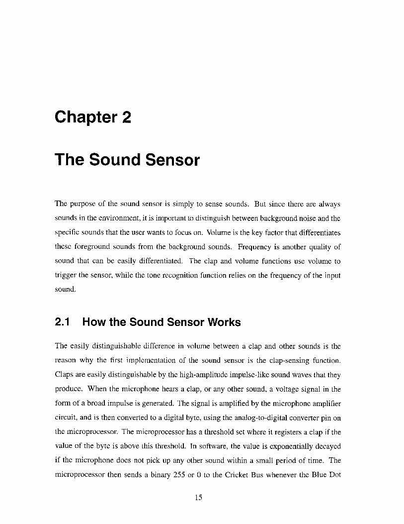
The electret microphone is connected to the Vdd of 5 volts through a 1.2 KQ and a 1
KQ resistor to result in a voltage divider. (See Figure 2-2.) The two capacitors, C2 and C3,
between the 1 KQ and 1.2 KQ resistors allow this node to be seen as an AC ground to the
small signals from the microphone, so that the input resistance seen by the AC signals is
smaller. The AC signals see 1.2 KQ, instead of the 2.2 KQ, in parallel to the microphone
resistance, while the DC voltage still sees a bias of 2.2 KQ above. The voltage signals at
this stage are very small and only range from tens to hundreds of millivolts. This voltage
divider is put through a DC coupling capacitor of 0.1 pF and is biased at 1.2V by the
resistive divider made by R3 and R4. This signal then goes to the positive input of the
MAX495, a single supply opamp from Maxim Integrated Circuits.
The opamp circuit amplifies the low-voltage signals from the microphone circuitry
using a non-inverted configuration. The negative input is connected to ground through a
1.5 KQ resistor, a 100 KQ potentiometer and a 4.7 pF capacitor connected in series. The
potentiometer allows the user to have access to the gain of the amplifier, thereby controlling
18
Clap Sensor v1.1Genee Lyn Colobong ([email protected])Ava Erickson ([email protected])MIT Media LaboratoryFebruary 19, 1999
U4
J 1 J 2 LM2931Z-5.0
C147 uF
RA2 RA1 LRA3 RA0O16
4 RA4 OSC2 15
5 MCLR Osi1 U3
RBO IRB7 4TM2 +5V8 R1 R67 1 j2_
-RB3 RB4
microprocessor c
C6 +5V
0.1 uF 1.2K cc C?
2C4 *
.. ._ 0.1 uFI
Figure 2-2: Sound Sensor Circuit Schematic
19
1M

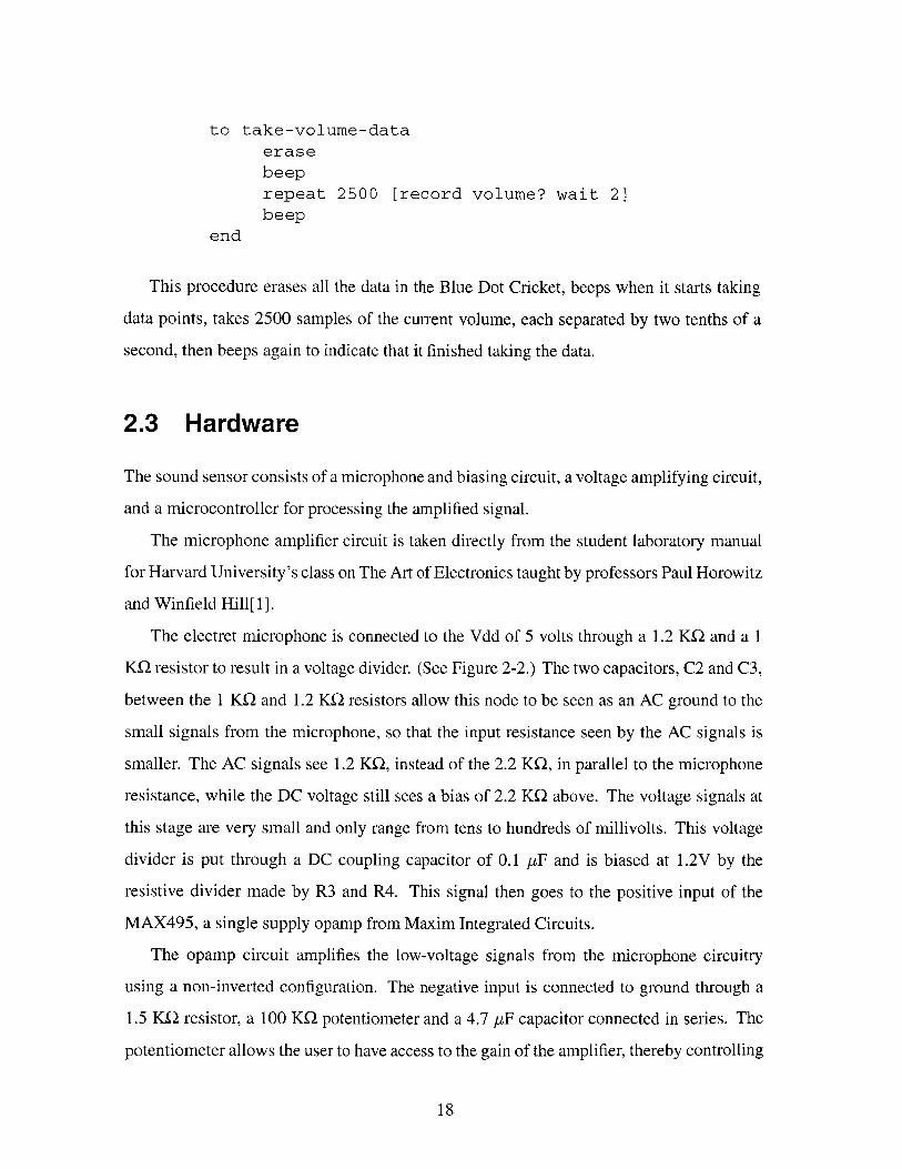
Figure 2-3: Sound Sensor Printed Circuit Board Layout: Component Side
the amplitude of the input signals and therefore the sensitivity of the device to its input. The
opamp has a 1 MQ feedback resistor connecting the output of the opamp to the negative
input, allowing amplifier gains from 10 to 1000. The output of the amplifier is then fed to
a pin of the microprocessor equipped with an analog-to-digital converter.
The signal processing from here on out is digital and handled by the microprocessor.
The microprocessor I used for this circuit is the PIC 16C715 from Microchip Technology,
simply for its analog-to-digital conversion capabilities [7]. The RBO/Interrupt input/output
pin of the microprocessor is tied to the bus line that is shared by all bus devices and the
Blue Dot Cricket. This allows changes on the voltage signal of the bus line to trigger an
interrupt on the microprocessor. A Cricket-standard 4 MHz ceramic resonator is used to
provide the clock signal.
Perhaps in the future, an 8-pin microprocessor also by Microchip Technology can be
used for this circuit instead. This can greatly reduce the size of the layout so that the board
becomes dominated by the microphone and potentiometer. The layout can be cut in half if
the PIC and other solder-mounted parts are placed on the opposite side of the through-hole
parts like the microphone, potentiometer and bus connectors. See Figures 2.3 and 2.3 for
the current layout.
Other parts that are included in the circuit are: two bus connectors that provide the +9
volts, ground and bus data signal, a 10 KQ resistor that ties the master clear pin of the
20

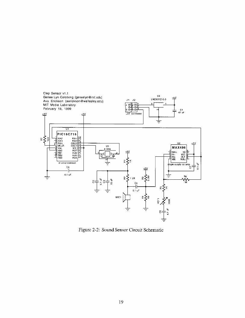
Figure 2-4: Sound Sensor Printed Circuit Board Layout: Solder Side
microprocessor to Vdd to keep the microprocessor from resetting, decoupling capacitors of
0.1 pF from Vdd to ground on both the microprocessor and the opamp, and a power supply
decoupling capacitor of 47 pF between the output of the 5-volt regulator and ground.
Table 2.1 is a parts listing of the Sound Sensor design.
2.4 Software
After the signal is digitized by the analog-to-digital converter pin on the microprocessor,
the software manipulates the signal to provide the outputs for the clap sensor function, the
volume sensor function and the tone recognition sensor function. See Appendix A for the
actual assembly language program written for the sound sensor.
2.4.1 The Clap and Volume Functions
First, the A/D converter is enabled and the result, adres, is stored in the t2 register. Then
the A/D converter is enabled again, and this time the result is stored in the t1 register.
See Figure 2.4.1. The two registers are compared, and if the new value is greater than the
previous value, then the previous value, t2, is loaded with the new value. If the previous
value is greater, then nothing is done. This routine is repeated 120 times, and afterwards
the t2 register contains the largest value that was sampled for those 120 cycles.
21
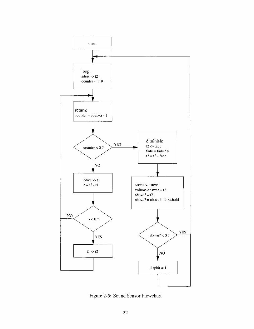
diminish:t2 -> fadefade = fade / 8t2 = t2 - fade
Figure 2-5: Sound Sensor Flowchart
22
store-values:volume-answer = t2above? = t2
above? = above? - threshold

Device Type1206 SMT capacitortantalum captantalum captantalum capJST connectorpotentiometer1206 SMT resistor1206 SMT resistor1206 SMT resistor1206 SMT resistorresistorceramic resonator+5v voltage regmicroprocessor
op ampmicrophone
Value0.1 pF15 p-F4.7 pF47 tF
100 KQ1.2 KQ10 KK21 KQ1 ME23.3 Mg4 MHzLM2931Z-5.0PIC16C715
MAX495
ReferencesC2 C4 C6 C7C3C5C1J1 J2POTIR2R7R1 R5R4 R6R3U3U4Ul
U2MIC 1
Price Ea.0.3550.28160.19740.55460.090.6640.029550.03240.029550.029550.02350.95880.504.19
2.481.239
Catalog No.PCC104BCT-NDP2014-NDP2011-NDP2017-NDJST B3B-PH-K3352E-104-NDP1.2KECT-NDP1OKECT-NDP1.OKECT-NDPl.OMECT-ND3.3MEBK-NDPX400SCT-NDLM2931Z-5.0-NDPIC16C715-04/
SO-NDMAX495CSA-NDP9931-ND
Table 2.1: Sound Sensor Parts Listing
Next, the value in t2 is loaded into the fade register, and fade is divided by
8. This value is subtracted from t2 and the result is the current volume, stored in
volume-answer, which ranges from 0 to 255. This number is given when the de-
vice is asked for its current volume. Under normal condition the volume hovers around
50.
To check for a clap or other loud sounds, the current volume is compared to a threshold
value, currently set to 128, and if the number is larger than the threshold, then the c lap bit
is set. If the number is lower than the threshold, nothing is done. The clap bit is cleared
later by the bus query routine. This allows the device to have a "memory," with which it
remembers if it heard a clap since the last time the device was queried.
The previous version cleared the c lap bit when the current volume is lower than the
threshold, but in that case, the device must be asked within tenths of a second that a clap is
given so that the sound sensor would register that a clap is heard. This is fine if the sensor
bus query is also in a tight loop that continually checks if a clap is heard or not. But this is
not often the case, since more than one sensor is usually used in Cricket projects and all the
sensors must be checked repeatedly if they have been triggered. This results in big loops
that do not query the sound sensor often enough to be able to register a split-second clap.
23
SupplierDigikeyDigikeyDigikeyDigikeyHeilandDigikeyDigikeyDigikeyDigikeyDigikeyDigikeyDigikeyDigikeyDigikey
DigikeyDigikey

With the way the clap function is currently implemented, the user can wait seconds or
minutes between queries and still be able to determine if a clap was heard within that time
period.
This process from the 120 samples to the determination of the volume and clap bit forms
the main loop of the program and is continually repeating, renewing the current volume
value and resetting the c lap bit based on the new volume level.
2.4.2 The Bus Protocol
The bus line is usually +5 volts or high. Whenever a command or data is sent through the
bus, it is preceded by 100 microseconds of a low or zero volts. This allows all the bus
devices connected to the bus network to finish whatever interrupt routine they may be in
so that they may be syncopated with the bus line when the actual 9-bit command or data is
sent.
In the case of the sound sensor, the bus data line is attached to the interrupt pin (RBO/INT)
of the microprocessor so that the main loop of the program can be interrupted when there
is activity on the bus line. This is not usually how the bus data is handled with other bus
devices.
With all the other bus devices made before the sound sensor, the main loop of the
program consisted of checking the bus line for a byte and then determining whether the
byte represented a command or data. Most of the time, the processor is stuck in the
bus - tyi loop waiting for a byte to come in. The real work for the sensor is usually done
during interrupts. The processor would be set up to handle a timer interrupt, and it is during
these interrupts where the sensor would actually process the signals and put the resulting
value into a result register. Whenever the correct bus command was sent, the number in
this result register would be stored into the bus-data register, and the bus-tyo code
would handle the serial transferring of the data from bus -data to the bus line, the bus
bit of the bus -por t register.
With the sound sensor, the main loop of the program is the actual sensor signal process-
ing, from the A/D converting of the signal on the input pin to the storing of the resulting
24

YES
NO
Figure 2-6: Bus Protocol Flowchart
25

value into the volume-answer register and the determination of the clap bit. The bus
line, attached to the interrupt pin, signals the processor to interrupt when a low is detected
on the bus line. The bus is handled during this interrupt and it either disregards the byte, if
it is data or a wrong command, or loads the result register onto the bus -dat a register and
outputs it serially to the bus line if the byte corresponds to the correct bus commands.
The 9-bit byte that is read from the bus bit of the bus -port register is loaded onto the
bus -data register and the carry bit of the s tatus register. The carry bit determines
whether the byte is a command or data. Data is usually ignored by the bus devices, and
usually only concerns the Blue Dot Cricket since it is usually the result given by some sensor
on the bus network. The commands are checked, by comparing the byte in the bus -data
register with the name of the device.
There are usually four names for each device, corresponding to the color of the LEGO
brick it is attached to, usually red, blue, yellow, or white. This scheme allows for four of
the same device to be attached to the bus network and be distinguishable from each other.
As previously discussed, the sound sensor comes in only two colors, green and blue, but a
third name is used to be able to refer to both. The hex value $68 refers to the green sensor,
the $69 refers to the blue sensor, and $6a refers to both.
If the names match, then the program waits for another byte to be read. This second
byte determines the function that the sensor is being asked to do. Currently, the sound
sensor responds to either the clap function, which is designated by a second byte of $01, or
the volume function, which is a second byte of $02. When the clap function is called for,
the processor checks the clap bit and loads either a 255 or a 0 onto the bus -data register
if the clap bit is set or cleared, respectively. Then the clap bit is cleared, as previously
discussed. If the volume function is wanted, the volume-answer register is loaded onto
the bus -dat a register.
2.4.3 Cricket Logo Macros
To get the sound sensor to the point where kids can actually use it in their Cricket Logo
projects, macros are written in the Cricket Logo compiler. The compiler is loaded upon
26

startup of the Cricket Logo page of Microworlds 2.0.3. See Appendix C for the compiler
macros.
These macros define the Cricket Logo commands given earlier as actual bus commands
and bytes. For example, the Cricket Logo command blue-c lap? is a macro for:
bsend $169 output bsr $01
The first byte sent is the name of the device, in this case, $169. The actual name of the
device is $69, but the $169 is sent so that the carry bit would be set. The set carry
indicates to all the bus devices on the network that each device should check if this bus
command is for them, instead of ignoring it as if it was a data byte. The macro bsend is
used whenever the Blue Dot Cricket sends a byte and does not expect a value to return.
The next byte sent corresponds to the function being queried, which in this case is the
clap function. The macro bsr is used when the Cricket sends the byte and expects a byte
in return. The byte returned, in this case, is 0 if there was no clap and 255 if there was a
clap. The macro output takes this returned byte as the output of the whole function, so
that the macro blue-clap? acts as a variable that equals either 0 or 255.
27

Chapter 3
The Voice Recorder
The voice recorder is a device that can record messages and play them back under program
control. A microphone on the device allows it to record messages, while a speaker connected
to the device allows the user to hear the played back messages.
The voice recorder is capable of recording messages of variable lengths, storing a
total length of 60 seconds. The messages can be stored in the ISD record/playback chip
indefinitely, but they can be written over through a Cricket Logo command.
The voice recorder is useful for automated playback of messages, since the Cricket can
control when to play which message.
3.1 How the Voice Recorder Works
The voice recorder uses the PIC16F84 microprocessor and the ISD2560 record/playback
chip. It has a three-pushbutton interface for play, record, and message number. It has a
microphone, a speaker, an audio amplifier circuit with a volume knob, headers for the bus
cables, and the necessary voltage regulator circuit for converting the 9 volts from the bus to
5 volts. The circuit is similar to the microcontroller/pushbutton mode circuit given in the
ISD2500 data sheet[4], but it includes the audio amplifier and the Cricket bus circuitry.
The record/playback chip is the central component of the voice recorder. It is the chip
that records and plays back the messages. The ISD is quite flexible, and has many modes
of operation. In order to control the chip properly, many input/output lines from the mi-
28

Figure 3-1: The Voice Recorder
29
croprocessor must be used to toggle the different pins of the ISD2560. The microprocessor
tells the record/playback chip when to record, playback or fast-forward through messages,
by receiving the input from the different buttons pressed or the Cricket Logo bus commands
and toggling the correct ISD input lines.
The ISD chip stores all the recorded data on chip. At the end of each recording, an End-
Of-Message (EOM) marker is stored at that address. An EOM output pin detects when an
EOM marker is is reached during playback or fast-forwarding, allowing the microprocessor
to know when a specific message is reached or when a message has reached its end.
3.2 How the Voice Recorder is Used
There are two user interfaces to the voice recorder: a direct manipulation pushbutton
interface, and a software interface. For the pushbutton mode, a record button, REC, allows
the user to record a message while holding down the button. A play button, PLAY, plays
back the current message. A message number button, MSG#, is used for fast-forwarding to
different messages. Pressing MSG# once will reset the message pointer to the first message.
The number of times that the MSG# is pressed will move the pointer to the beginning of
that message number. Pressing PLAY afterwards will playback that message number.
Playing back a message can be done by pressing the PLAY button or through a Cricket
Logo command that also specifies which message is to be played. Playback of a specific
message can also be accomplished through the pushbutton mode by fast-forwarding through
the messages before the specific message the user wants to play and then pressing the PLAY
button. The user can also cycle through the recorded messages by pressing the PLAY button
once in the beginning and then at the end of each message. The unrecorded space, if there
is any, at the end of the recorded messages is treated as a single message and it is finished
at the end of the 60 seconds. Pressing the play button then will replay the first message.
The Cricket Logo interface currently has the record-over Cricket command imple-
mented, which allows the user to start recording from the beginning of the message space,
effectively "erasing" the messages that are recorded over. Also, a play command allows
the Cricket to play back a certain message.
30

The voice recorder keeps track of the number of messages recorded, and whenever the
REC button is pressed to begin a recording of a new message, the device increments this
number and fast-forwards to that message number, so that the new recordings are always at
the end of the previously recorded messages. The record-over Cricket command sets
this number to zero so that the next recorded message will be placed in the beginning of the
message space.
To demonstrate the play command, here is an example of a Cricket Logo procedure.
This procedure checks the clap sensor, and plays back the 5-second long message, message
3, whenever a clap is heard.
to sayhiloop [ if clap? = 255 [play 3 wait 50] 1end
The command play 3 plays the 3rd message, and the wait 50 command waits for 5
seconds so that subsequent claps would not try to play the 3rd message again while it is
already playing.
3.3 Hardware
The circuit for the voice recorder consists of the voltage regulator circuitry, the micropro-
cessor circuitry, the record/playback chip circuitry, and the audio amplifier circuitry. The
voltage regulator circuit is a Cricket-standard circuit used to provide the power from the bus
to the whole chip. The only difference is that in the voice recorder, the power and ground
are separated into analog and digital. The microprocessor part consists of the connection
of control lines to the record/playback chip and to the LED and pushbutton switches. The
circuit for the ISD record/playback chip is taken directly from the ISD manual1 , which pro-
vides the exact capacitor and resistor values for the decoupling and biasing of the different
pins. The audio amplifier circuit is taken from the LM386 data sheets[9], also to provide
the exact component values for the decoupling and biasing of the amplifier.
IISD2500 Application Example-Design Schematic. ISD, pg. 1-100.
31

Voice Cricket 1.1MIT Media Lab (C) 1999Genee Lyn ColobongMarch 1, 1999
C4
9 V I i-H LA2 XcVk 25 .0.001 uFJ1 J2 5 A24 AGND
6 A4 P 23 -7 A5 C 22 DUrO
391A6 ~21A7 AnaOut 20
1C A8 Analn 19
1 1 A9 AGC 181 Auxln MicRef 1 713 Vssb Mic 161 4 Vssa Vcca 15SP+ SP- - A +5V -A +5V evoice rec/play chip
- -* 4.7 u F ) (D Y
AGND DGO- 0.1 uF 1 K7
22 uF
T 220 uF
AGND
AGND
Figure 3-2: Voice Recorder Circuit Schematic
32
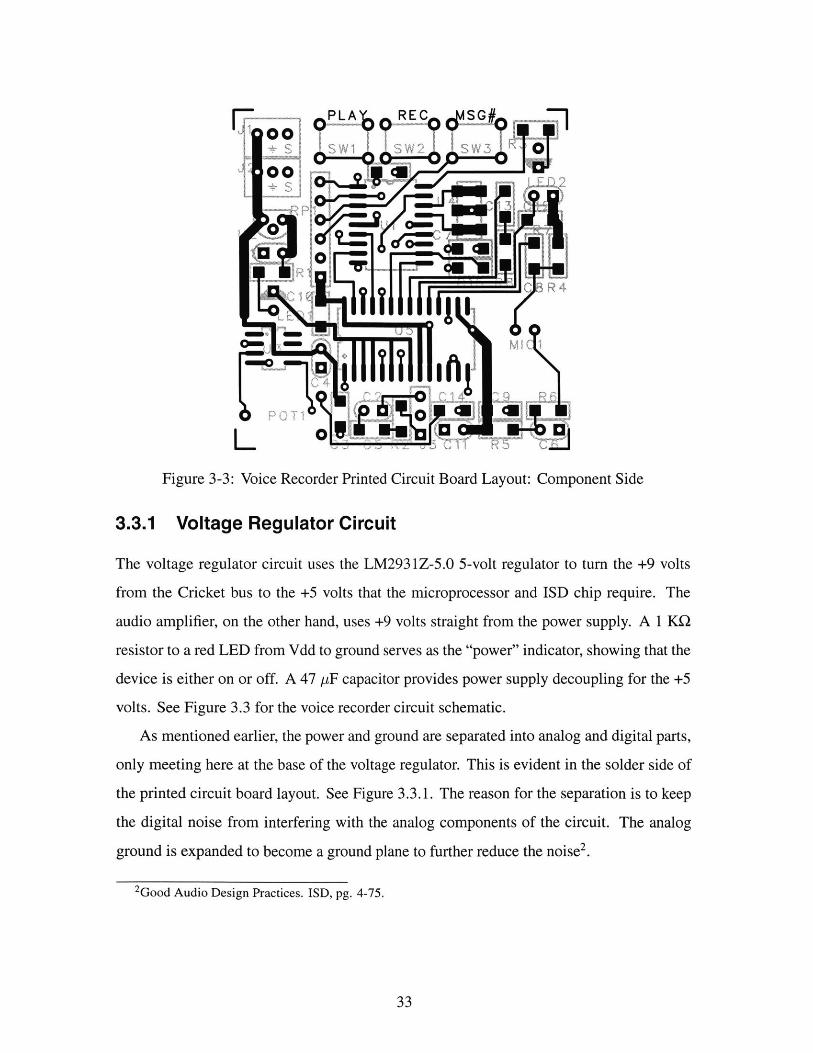
Figure 3-3: Voice Recorder Printed Circuit Board Layout: Component Side
3.3.1 Voltage Regulator Circuit
The voltage regulator circuit uses the LM2931Z-5.0 5-volt regulator to turn the +9 volts
from the Cricket bus to the +5 volts that the microprocessor and ISD chip require. The
audio amplifier, on the other hand, uses +9 volts straight from the power supply. A 1 KU
resistor to a red LED from Vdd to ground serves as the "power" indicator, showing that the
device is either on or off. A 47 pF capacitor provides power supply decoupling for the +5
volts. See Figure 3.3 for the voice recorder circuit schematic.
As mentioned earlier, the power and ground are separated into analog and digital parts,
only meeting here at the base of the voltage regulator. This is evident in the solder side of
the printed circuit board layout. See Figure 3.3.1. The reason for the separation is to keep
the digital noise from interfering with the analog components of the circuit. The analog
ground is expanded to become a ground plane to further reduce the noise2.
2Good Audio Design Practices. ISD, pg. 4-75.
33
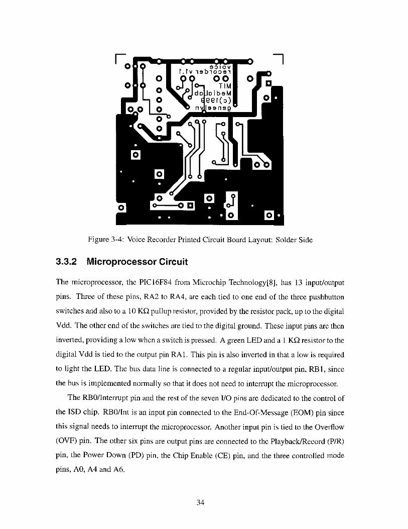
Figure 3-4: Voice Recorder Printed Circuit Board Layout: Solder Side
3.3.2 Microprocessor Circuit
The microprocessor, the PIC16F84 from Microchip Technology[8], has 13 input/output
pins. Three of these pins, RA2 to RA4, are each tied to one end of the three pushbutton
switches and also to a 10 KQ pullup resistor, provided by the resistor pack, up to the digital
Vdd. The other end of the switches are tied to the digital ground. These input pins are then
inverted, providing a low when a switch is pressed. A green LED and a 1 KQ resistor to the
digital Vdd is tied to the output pin RA1. This pin is also inverted in that a low is required
to light the LED. The bus data line is connected to a regular input/output pin, RB 1, since
the bus is implemented normally so that it does not need to interrupt the microprocessor.
The RBO/Interrupt pin and the rest of the seven I/O pins are dedicated to the control of
the ISD chip. RBO/Int is an input pin connected to the End-Of-Message (EOM) pin since
this signal needs to interrupt the microprocessor. Another input pin is tied to the Overflow
(OVF) pin. The other six pins are output pins are connected to the Playback/Record (P/R)
pin, the Power Down (PD) pin, the Chip Enable (CE) pin, and the three controlled mode
pins, AO, A4 and A6.
34

The microprocessor also uses the Cricket-standard 4 MHz ceramic resonator as a clock
input, and the 10 Ki resistor from MCLR to the digital Vdd, provided by the 10 KG x 5
resistor pack.
3.3.3 Record/Playback Chip Circuit
The record/playback chip circuit has the ISD2560 as its main component. The 2500 series
was chosen because it was used previously and successfully in another project within the
group. The 60-second version was chosen over the other lengths because it was long enough
to hold a substantial amount of messages, and the quality of the output was better than with
the longer versions. The 2500 series uses the same amount of memory allocation for the
different recording lengths, but the sampling rate is changed to accomodate the different
lengths. The slower the sampling rate, the less information is stored during the recording,
but the longer the recording length can be.
As discussed earlier, several control lines of the ISD2560 are connected to the in-
put/output pins of the microprocessor. These pins control exactly what the record/playback
chip does, telling it exactly when to start recording, stop recording, start playing back,
reset, and fast-forward. The ISD also has ten address pins (AO to A9) that can correspond
to the exact address of the message space. This was not too useful for the voice recorder
application though, since the messages are treated as units of message space that are not
separable.
The other use for these address pins are as mode selectors. The 2500 series is capable
of operating in several modes. The modes available are MO-message cueing, M1-delete
EOM markers, M3-message looping, M4-consecutive addressing, M5-CE-level activated,
and M6-push-button mode. The modes that I thought would be useful to control are modes
0, 4 and 6, so these pins are tied to microprocessor output pins, while the rest are either tied
to digital ground to not ever be used.
The Vccd and Vcca are digital and analog power supply pins for the ISD. Each pin
has a 0.1 tF power supply decoupling capacitor to ground, C9 and C 10. C11, the 22 pF
capacitor on the Vcca line, is another bypass capacitor for the analog Vdd.
35

The Chip Enable line has a 0.001 puF capacitor, C15, connecting it to the digital Vdd.
This is to prevent "unexpected records" that can occur during power up. If the P/R pin
happens to power up on the recording setting, and CE goes high slower than the Vccd of the
chip, due to loading and capacitance, a short recording might occur and an EOM marker
might be placed immediately after it. This effectively moves the addresses of the previously
recorded messages up by one, and the first message is no longer the first recorded message,
but a blip of sound instead. The capacitor tying the control pin to Vccd would bring the pin
voltage up with Vccd, since the voltage across a capacitor cannot change instantaneously. 3
The 0.1 pF capacitor, C13, and the 5.1 KQ resistor, R8, that tie the Analog Input pin to
the Analog Output pin provides an additional low frequency pole to help the cutoff at the
low end of the voice passband. If a microphone is not used, the input signal would be fed
directly to the Analn pin, and the AnaOut pin would provide the preamplifier output.
The AGC is the Automatic Gain Control input, which adjusts the gain of the preamplifier
dynamically. R7 and C 12, the resistor and capacitor tied to the pin in parallel provide the time
constants used to determine the "attack" and "release" time for the gain of the preamplifier.
The MicRef and Mic lines are connected to the two ends of the microphone through
0.1 pF decoupling capacitors, C7 and C8. The capacitors also provide single-pole low-
frequency cutoff and common mode noise rejection. The resistors, R4, R5 and R6, are bias
resistors for the microphone. C6, the 220 piF capacitor, reduces the power supply noise of
the analog Vdd.
3.3.4 Audio Amplifier Circuit
The audio amplifier circuit amplifies the output from the ISD record/playback chip and
feeds it to the speaker. The low-voltage signal from the SP+ pin of the ISD chip goes
through an AC coupling capacitor, C14, and the 50 KQ potentiometer to the positive input
of the LM386 amplifier. The potentiometer serves as a volume knob, reducing or enlarging
the resistance of the input signal to give a louder or softer output. The negative input of
the amplifier is tied to ground. The amplifier is set to a gain of 20, which is accomplished
3Unexpected Record. ISD, pg. 4-24 to 4-25.
36

Table 3.1: Voice Recorder Parts Listing
by leaving the two gain pins, pins 1 and 8, not connected. This is the lowest gain that the
amplifier is able to accommodate, and I did not find the circuit to need any more gain than
20. This is partly due to the +9 volts that the LM386 uses for a supply voltage, allowing
the output to be amplified to up to +9 volts. The output of the amplifier goes through a 220
piF capacitor to one side of the 3-pin header, which connects to the plus side of the speaker.
The other side of the 3-pin header is tied to ground, also grounding the negative side of the
speaker. The 0.047 puF capacitor and 10 Q resistor are for filtering. The 10 puF and 0.1 p-F
capacitors provide power supply decoupling for the +9 volt supply voltage.
Table 3.1 is a parts listing of the voice recorder design.
37
Device Type1206 SMT capacitor1206 SMT capacitor1206 SMT capacitor
tantalum captantalum captantalum captantalum captantalum cap3-pin female headerJST connectorhi-eff LED, redhi-eff LED, greenmicrophone
potentiometer1206 SMT resistor1206 SMT resistor1206 SMT resistor1206 SMT resistor1206 SMT resistorresistor packpushbutton switchceramic resonatorvoice rec/play chip+5V voltage regaudio amplifiermicroprocessor
Value0.001 pF0.047 pLF0.1 pF
10 pF22 pF220 tF4.7 pF47 pF
HLMP1700HLMP1790
50 KQ210 KGIOQ1 KQ470 KQ5.1 KQ10 KQ x 5
4 MHzISD2560GLM2931Z-5.0LM386PIC16F84
ReferencesC15C5C3 C7 C8 C9
CIO C13 C14C4CliC2 C6C12C1J3J1 J2LEDILED2MICiPOTIR4 R6R2RI R3 R5R7R8RP1SWl SW2 SW3U4U5U2U3U1
Price Ea.0.1580.3040.4054
0.3360.4594.350.2720.7080.0830.090.2820.2821.2391.000.0510.0960.0510.0960.0960.150.22941.1598.63520.52520.32524.19
Catalog No.PCC102BCT-NDPCC473BCT-NDPCC104BCT-ND
P2013-NDP2015-ND540-220M06P2024-NDP2017-ND929974-01-03JST B3B-PH-KHLMP-1700QT-NDHLMP-1790QT-NDP9931-ND3352E-503-ND4 P1OKECT-NDP1OECT-ND4 P1.OKECT-NDP470KECT-NDP5.1 KECT-ND264-10KSW400-NDPX400SCT-NDISD2560G-NDLM2931Z-5.0-NDLM386M-1-NDPIC16F84-04/SO-ND
SupplierDigikeyDigikeyDigikey
DigikeyDigikeyMouser
DigikeyDigikeyRicheyHeiland
DigikeyDigikeyDigikeyDigikeyDigikeyDigikeyDigikeyDigikeyDigikeyMouser
DigikeyDigikeyDigikeyDigikeyDigikeyDigikey

3.4 Software
The assembly language code for the microprocessor can be broken up into four parts: the
main loop and button/bus handling, the record sequence, the playback sequence, and the
fast-forwarding sequence. See Appendix B for the actual assembly language program for
the voice recorder.
3.4.1 The Main Loop and Button/Bus Handling
The main loop consists of checking for the low in the bus data line, meaning that a byte is
coming in, and checking the three buttons for a low, meaning one of the three buttons is
pressed. Usually, the main loop would spend most of its time waiting for the bus line to go
low, but in the case of the voice recorder, the pushbutton inputs are just as important as the
bus inputs, so the loop checks the four input lines at the same rate.
Bus Handling
When a byte arrives on the bus and is loaded onto the bus-data register, the carry bit
is checked to see if the byte corresponds to a command or data. If it is a command, it is
checked to see if it has the correct name. The voice recorder comes in four names (in hex
below), corresponding to four colors: $54 for red, $55 for blue, $56 for yellow and $57 for
white. This is the usual way that a bus device is named. If the name does not match, then
it returns back to the main loop.
If the name does match, a second byte is received. Currently, there are only two
Cricket Logo commands that can be given to the voice recorder. If it is the record-over
command, then an $ff is received and the msgnum register, which contains the number of
messages recorded on the device, is cleared and written on the EEPROM of the PIC 16F84.
It must be written on the EEPROM so that the device does not forget the number of
messages it has when powered down. Upon startup, the device reads this information from
the EEPROM and stores it again in the msgnum register.
Any other number received as the second byte corresponds to the message to be played
back, which is the only other Cricket Logo command that the voice recorder can receive.
38
This number is stored into the nthmsg register and is reduced by one, so that play 1,
which means "play the first message" to the user, will be read as "play the zeroth message
in the message space", which is in fact the first message. Then some initialization is done:
resetting the chip by pulsing the PD pin, resetting the state bits, checking the pnbit if
more initialization is required, and setting the P/R pin to play. If the number in nthmsg is
larger than zero, then the bus f f bi t bit of the bits register is set and the code branches
to the fast-forward section, to fast-forward to the beginning of the next message, and jumps
back when it checks if the bus f fbit is set. The bus f fbit is cleared and nthmsg is
decremented. This is repeated until the number in nthsmsg is zero. Then it jumps to the
play sequence to playback the message that the pointer is currently pointing to. Then the
code returns back to the main loop.
Button Handling
The buttons are also checked to see if they have been pressed. If REC is pressed, then the
code branches to the record sequence and begins recording. If PLAY or MSG# is pressed,
then some state bits are checked to see which part of the playback or fast-forwarding
sequences it should jump to.
The device is initialized so that the P/R is set to play, modes 0 (the message-cueing
mode) and 4 (the consecutive addressing mode) are cleared, and mode 6 (the pushbutton
mode) is set. All the other state bits in the bi ts register are cleared.
3.4.2 The Record Sequence
The record sequence is currently only accessed through the pushbutton mode, by actually
holding down the REC button to record a message. In the record section, the msgnum
register is loaded to see how many messages have been recorded on the device since the last
time the record-over Cricket Logo command was sent. If the number is not zero, then
the code branches to record2 which fast-forwards through the messages until the pointer
is set to the end of the last message, so that this to-be recorded message will be recorded at
the end of the current message space.
39

Figure 3-5: The Record Sequence State Diagram
40

In record, the P/R pin is set to record, and mode pins 4 and 6 are set. The green
LED is turned on, and the chip enable line is pulsed to start the recording. The wai trec
loop waits until the button is no longer pressed or an overflow occurs. When the button is
let go, the stop-recording sequence begins. CE is pulsed again to stop the recording, the
msgnum register is incremented and written onto the EEPROM, the mode 4 pin is cleared
to disable consecutive addressing, the P/R is switched to the safer play state, and the green
LED is turned off. If an overflow occurs, meaning that the chip has reached the end of
its 60-second message space, the code branches to recovf, which goes through the same
stop recording sequence without waiting for the button to be let go.
The r e c ord2 code is the same as the re c ord code, but it contains the fast-forwarding
loop rec f f which is repeated the same number of times as there are number of messages
in the msgnum register. The fast-forwarding process will be explained more in detail under
the Fast-Forwarding Sequence section.4
The record sequence does not change any of the state bits, though mode bits 0 and 4
are toggled to allow the fast-forwarding in record2. The fast-forwarding sequence relies
heavily on the correct setting of these two modes.
3.4.3 The Playback Sequence
Pressing the PLAY button immediately brings the code to playinit. The playinit
checks the f fbit of the bits register to see what state the device is currently in. If
f fbi t is set, then the device has just been fast-forwarded, and the message space pointer
is currently pointing to a message other than the first message. If the f fbi t is not set,
then the message pointer is pointing to the beginning of the message space, and the play
sequence would begin playing back the first message.
The playback section consists of play, which ends in playloop, playnext1,
also ending in playloop, and then the three ending branches stop, playeom, and
playovf, which ends the playback sequence.
The ordinary play sequence already has P/R set to play, and it clears the resetbit.
4The record2 code would not have been possible without the ISD Application Notes and Design Manualon Circuit Examples, page 4-61, in the ISD Data Book.
41
ffbit = 0
Figure 3-6: The Playback Sequence State Diagram
42
ff bit = 1I
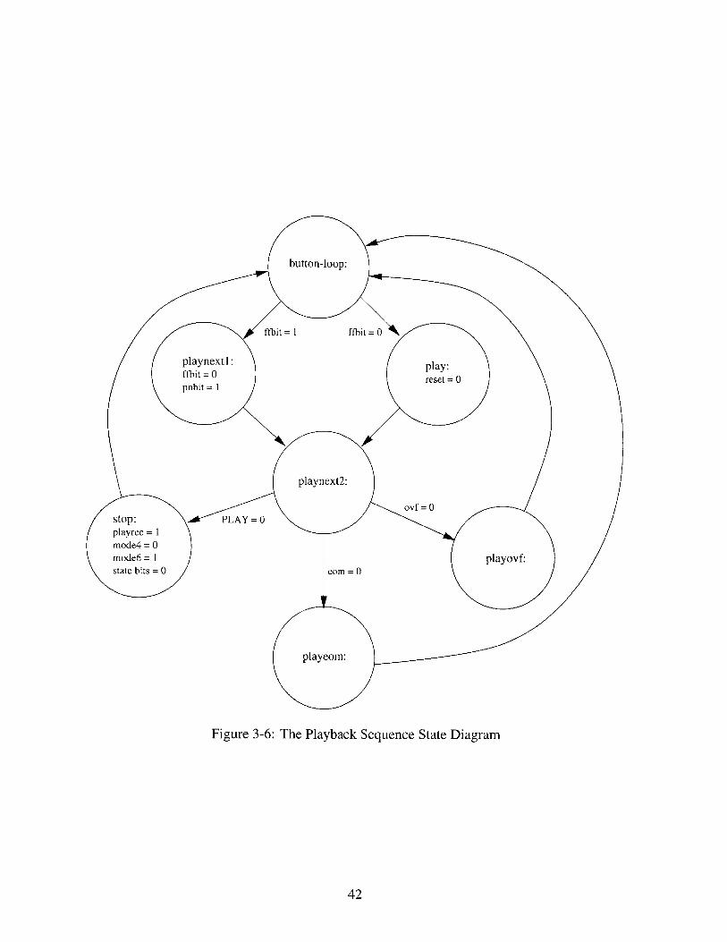
The playnext2 code follows, which has the actual playback sequence, turning on the
green LED, and pulsing CE to start playing the first message. While the message is playing,
the code is stuck in playloop, checking to see if the PLAY button is pressed again, if
the end of the message is reached, or if the chip has reached the end of its memory space.
Pressing the PLAY button while the message is in the middle of being played back signals
the device to stop playing the first message and reset. The end of the message is signaled
by a low on the EOM pin of the ISD, and the overflow is signaled by a low on the OVF
pin. In the s top branch, the device is reset, the mode and state bits are reset to their initial
settings, and the green LED is turned off. In the playeom branch, the message ends and
all that has to be done is turn the green LED off. In the playovf case, a pulse on CE
resets the message space pointer, and the green LED is turned off.
If the device is already pointing to a message other than the first, then the mode bits
are configured to a different setting, allowing the fast-forwarding to have occurred. This
current setting can not be disrupted, or else the device will return back to the beginning
of the address space. In playnext1 the f fbit is cleared and the pnbit is set, going
into another state. The message is played back, by branching to playnext2 and the code
returns to the main loop.
All subsequent playbacks play the message after the one just played. But since the
device was fast-forwarded to get to the first played back message the mode bits are still set
to the unusual settings. This is changed when another button is pressed, a bus command is
given, or the message is stopped in the middle of its playback. If the MSG# is pressed, then
the code branches to resetmodes since the pnbit is still set. The record code also
reinitializes the state bits and sets the mode bits to the settings that allow it to record. The
bus command, which leads to playnnth, also clears the state bits and makes a branch to
resetmodes if the pnbit is set. The stop code also reinitializes the state and mode
bits.
43

Figure 3-7: The Fast-Forwarding Sequence State Diagram
3.4.4 The Fast-Forwarding Sequence
A low on the MSG# line allows the code to branch to msginit. The msginit checks
two bits to see which state the device is currently in. If the two bits are cleared, then it is
the first time that the MSG# is pressed and the code branches to reset which points the
pointer to the beginning of the message space.
The reset code turns on the green LED, sets the resetbit, resets the mode bits if
the pnbi t is set, waits a millisecond so that the lit green LED can be seen, reinitializes the
message space pointer to the beginning, and turns off the green LED.
If either the resetbit or f fbit is set, then the code branches to fastf, which
means that the MSG# button was already pressed at least once before. If the resetbit is
set, then the pointer should be fast-forwarded so that it is pointing to the beginning of the
44

second message. If the f f bi t is set, then the pointer is already pointing to the beginning
of a message other than the first one, and it should be fast-forwarded again to point to the
message after that. In f astf, the resetbit is cleared, the mode pins are set so that the
fast-forwarding is enabled, (mode 6 is cleared, and modes 4 and 0 are set,) and CE is pulsed
to begin the fast-forwarding.
At this point, the RBO interrupt is enabled. The low on the EOM pin can occur anytime
depending on the length of the message being fast-forwarded. In the meantime, the eombi t
is polled in f f loop. When the interrupt occurs, the eombi t is set in the int -routine,
and the code returns to the f f loop which it can now exit. The RBO interrupt is disabled,
the eombi t is cleared and mode 0, the message cueing mode, is returned to its normal state.
The green LED is turned on and off to show the user that the device has fast-forwarded to
the next message. The bus f fbit is checked to see if this was for a bus command, and
the code returns if the bit is set. If it is not set, then the f fbit is set signifying that the
pointer is now pointing to the beginning of a message other than the first.
45
Chapter 4
Field Test: The Community Arts
Center Workshop
The workshop was held at the Community Arts Center in Cambridge, Massachusetts with
six or seven 10- to 12-year-old children. It consisted of five 2-hour afternoon sessions
spread out over three weeks in April 1999. The Center runs an afterschool program for the
children with set classes from 3 to 5pm, and the workshop became a replacement for one
of these classes, photography, for the three week period.
The photography teacher was forced to cancel the class, and as a result, the children that
I worked with didn't actually express interest in Cricket Logo, but were somewhat forced
to participate in the workshop due to the situation. There were six children signed up for
the Cricket workshop, but towards the end, only four remained. The seventh child joined
us for the second day and was able to create something in the span of two hours, but she
didn't return for the following days.
The goal was to introduce the children to Cricket Logo and have them build their own
LEGO creations that operated with a program and had behaviors that are related to sound.
This workshop would be the first time that the children would get to work with the Sound
Sensor or the Voice Recorder. Incorporating these devices into their Cricket projects would
easily result in a LEGO creation that could respond to sound or output sounds.
The children who attended the workshop were: Steve, John, Gene, Mary, Samantha,
46

Lisa and sometimes Molly.1 The group consisted of three boys and three girls. The
children who remained until the end are the three boys, Steve, John and Gene, and one girl,
Mary. The children came from neighboring schools, and they regularly attended the CAC
afterschool program. Steve went to a nearby private school, while the other children went
to a public school.
Beth Rochefort was my main contact at the CAC, and she provided me with the children
and the rooms. I thought that she would be able to participate in the workshop as well, but
she had her own kids to look after, leaving me to supervise the six children by myself.
4.1 Day by Day Narrative
On the first day of the workshop, the Community Arts Center was not able to let me use the
computer lab. Instead, Beth let me share a somewhat large room with another group. The
space was accomodating, but the computers were lacking. Only one computer was useable,
leaving me with only two computers for the day, since I had brought only one laptop. I
anticipated having three computers so that the six kids can break into three groups, but this
was not the case. Instead, we had a laptop and a desktop that needed to be shared among
six children. This situation meant that only two kids could type at a time, and that four kids
would have to watch patiently at a time. This proved to be difficult with 10- to 12-year-olds.
The materials I brought to the workshop are the Crickets, red (small) and gray (high-
powered) motors, and a variety of sensors such as light, touch, temperature, and reflectance.
I also brought plenty of 3-digit displays and sound sensors, and three or four voice recorders
and speakers. For building materials, I brought a big tub of LEGO parts, but I quickly learned
that the collection of LEGO parts was missing some very important key parts that our lab
had run out of. These parts included axles longer than 4 inches and axle connectors, which
are necessary when using the gray motors. The lack of these key parts made for some
creative solutions, but often resulted in frustration for the children.
I began the workshop by showing them a demo of the BopIt game, built by Chris
Hancock and Bakhtiar Mikhak, graduate students from the Epistemology and Learning
47
'These are not their real names.

Group. The Cricket version of the BopIt game consisted of two mechanisms: a lever that is
bopped, or pressed, and a handle that is twisted. The Cricket that controls the BopIt picks
one of the two mechanisms randomly, and the voice recorder would either say "Bop It!" or
"Twist It!" depending on which device the user is to bop or twist. A timer begins running
as soon as the Cricket chooses one of the mechanisms and if the user's response is too slow,
then the user loses. The children received it with delight, crowding around the game to
watch each other play.
After showing them the BopIt, the rest of the day was introduction and experimentation.
The children split up with girls on the laptop and boys on the desktop. The boys were
immediately envious of the laptop, and the children did not seem at all interested in sharing
and working together. Nevertheless, we went through the motor commands, then began
experimenting with the sensors.
Steve seemed to be the most interested in Cricket Logo of the six kids. He was able
to learn the motor and sensor commands very quickly, but his LEGO building skills were
lacking. After having the kids control a motor attached to a Cricket through Cricket Logo, I
had them build a car with LEGO pieces so that they were able to control their own creation
instead of just a motor. Steve couldn't seem to see the next step in the building process,
and he was always frustrated because he didn't know how to get to the finished product.
As soon as he was able to control his car-like creation with the simple motor commands,
he started over with the sensors, and didn't bother to add the sensors to his car. He didn't
even modify or improve his LEGO car, as the other kids were more inclined to do. He then
played with the sensors to see what kind of numbers they produced, by attaching a 3-digit
display to the cricket and roaming around the room to measure light, sound, temperature,
etc.
The other children did not show the same enthusiasm. John immediately mentioned
that he did not have any interest in the Crickets or programming. He spent some of his time
with the hardware, connecting the sensors, motors, and bus devices to the Crickets in all
sorts of ways.
The girls found some interest in the voice recorder. They quickly learned the push-
button interface, and began recording messages and sounds. I noticed that the girls could
48

immediately get meaningful play out of the voice recorder. The girls did not have to learn
how to program it in order to use it, unlike the other devices. Samantha is a shy girl and
I couldn't get her to actually say her own messages while I was teaching her how to use
it. She ended up using the voice recorder to say hello messages to her friends, and also to
record notes to herself that day. Lisa and Mary recorded little songs that they played on the
piano.
The second day was much more productive. First, I was able to use the computer lab,
giving me access to six computers. I did not bring enough interface Crickets though, so the
children had to share five computers between them. I encouraged them to work with each
other, but maybe the scenario of the first day made them realize how much they value having
their own Cricket Logo station. Still, the five computers greatly improved the productivity
for that day.
Second, I had brought with me several Cricket-savvy colleagues from the Epistemology
and Learning Group, Fred Martin, Bakhtiar Mikhak and Michelle Shook, so that the teacher
to student ratio was almost 1:1. The children definitely made use of all of the available
help. The adults were found busy helping with everything from LEGO part searching to
Cricket Logo programming.
That day, I had the children begin working on a car-like project that would be controllable
by the environment around it. They basically had to build a LEGO car, attach the motor
and sensor to it, and program it to go forward when the sensor is triggered.
Everybody seemed to have a good time with the LEGO building. The LEGO parts were
spread out on the floor and the kids and adults sat around them building their cars. This
was not too easy a task, though, with the still-missing LEGO parts.
Lisa was able to make a pretty wide car by joining two or three short rods to form one
axle. But without the axle connector LEGO piece, she had to use the smallest 8-tooth gears
and stoppers to connect them. Though she managed to piece it together, she was not able
to attach a Cricket or any weight to her car because the axles were so frail. She ended up
starting over, following the design of one of the other kids.
Molly, who joined us only for that day, seemed very interested in the car-building
project. She was very apt in the LEGO building part, constructing a car that seemed strong
49
and stable, and held the Cricket securely. I ran through the different sensors she could
use to control the car, and she lit up when I mentioned the clap sensor. With my help, we
incorporated the clap sensor to her car and we first programmed the Cricket to just turn
the motor on when a clap is heard. After downloading, she put her car on the floor and
clapped. It worked! The car slowly moved forward and kept moving until it almost hit a
chair. She was very excited to see her car work. I showed her how to use the wait and
reverse direction (rd) commands, and she began experimenting with the existing program
to get her car to do more interesting things. This process of programming and then testing
by putting the car on the floor and then clapping caught the attention of everybody in the
room. Soon, John and Gene started clapping to control her car. After this, all the children
wanted to use a clap sensor with their projects.
On the third day of the workshop, we were allowed to the use the computer lab again,
but this time, there was no other adult that was available to help with the workshop.
The children had saved their car projects from the previous day, so we spent the day
working on them.
Again, the children weren't as productive. Some of them were frustrated that I wasn't
able to help them with their problems immediately, and they told me so. Some of them got
bored and began looking for other software on the computers to keep them entertained.
Steve, Samantha and Lisa started playing with the turtles in Microworlds, which they
got to see at a recent visit to the Media Lab. Gene started playing with the voice recorder
and started recording some obscene sounds like supposed flatulations and heavy breathing.
Molly didn't join us that day, or for the rest of the workshop. So John, who found LEGO
building frustrating, took her project and tried to turn it into his own. He removed the
wheels and several of the bricks and turned it into a boat by adding a propeller on the
bottom. He would go to the bathroom with the boat and try and make it move, despite my
warnings that he shouldn't get the Cricket wet.
For the fourth day of the workshop, we were given an entirely new room. Without any
desktop computers whatsoever, I was forced to bring several laptops. This worked well
enough, since all the children preferred working with laptops over desktops. Several kids
that did not participate in the workshop were all of a sudden very interested in what our
50
group was doing, encouraging the kids that I was working with to have more interest in the
workshop that day.
The children had a productive day, with the help of Cricket Logo experts, Tim McNerney
and Clint Sieunarine. Tim mentored Gene, spending the whole afternoon with him, and they
seemed to be the most productive group that day. Their finished product was a fast, smart
car that reversed direction and played one of Gene's messages depending on the number
of claps it heard. Based on Gene's wishes, Tim had the tough job of coming up with the
program that would count the number of claps it heard and respond to it. He suggested that
this functionality be added to the sound sensor so that the kids could use it easily in their
programs. He noted that it was the first thing that Gene thought of when they decided to
add both the clap sensor and the voice recorder to his car.
I had Mary and Steve think about the kinds of sensors that they wanted to add to their
projects. We put together a list of inputs and outputs that our Cricket workshop supported,
hoping that we could brainstorm together. I was not able to show them the volume function
of the sound sensor before, so I had them test it out. Because I was unprepared, I didn't
provide suggestions on how this command can be used in their projects, so the idea of
incorporating the volume sensor was abandoned.
Mary was inspired by the procedure called "to dance" from the Introduction to Cricket
Logo handout that I gave them that day. She rewrote the procedure for her car, changing
the sensor inputs. Her dancing car then needed some music to accompany the movements,
and instead of using the Cricket beep and note commands, I suggested that she use the
voice recorder to play the songs for her project. I thought that she might just sing into the
voice recorder, but her first thought was to record songs from the radio. She wasn't able
to record an entire song though since the device can only record 60 seconds long. The
recordings came out with enough clarity that the people in the room thought that somebody
had turned the radio on. She was able to integrate the voice recorder and speaker into her
dancing car, by making the LEGO base big enough to hold the devices, but then the little
red motor became too weak to move the dancing car back and forth. The next workshop
day, she changed the structure of her car so that she could use the bigger gray motors that
were powerful enough to withstand the weight of her dancing car.
51

I
Figure 4-1: Mary's Dancing Car
52
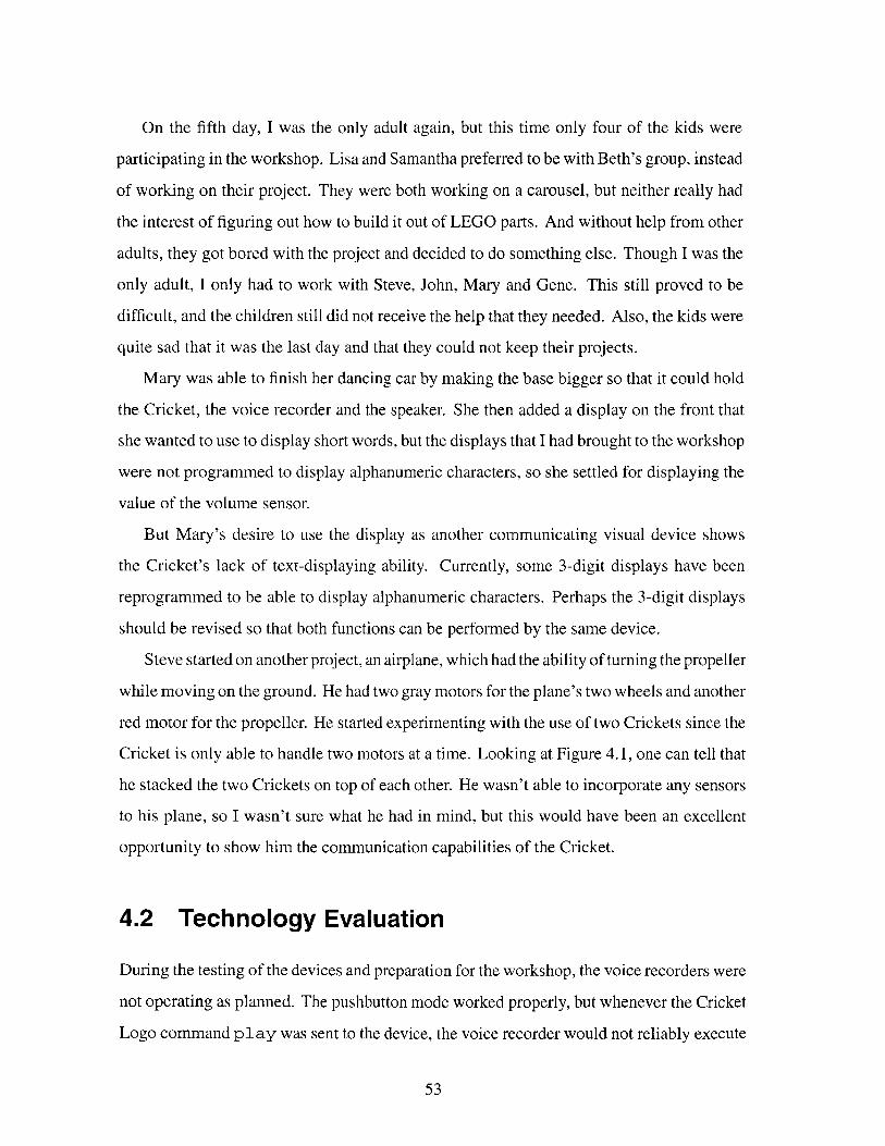
On the fifth day, I was the only adult again, but this time only four of the kids were
participating in the workshop. Lisa and Samantha preferred to be with Beth's group, instead
of working on their project. They were both working on a carousel, but neither really had
the interest of figuring out how to build it out of LEGO parts. And without help from other
adults, they got bored with the project and decided to do something else. Though I was the
only adult, I only had to work with Steve, John, Mary and Gene. This still proved to be
difficult, and the children still did not receive the help that they needed. Also, the kids were
quite sad that it was the last day and that they could not keep their projects.
Mary was able to finish her dancing car by making the base bigger so that it could hold
the Cricket, the voice recorder and the speaker. She then added a display on the front that
she wanted to use to display short words, but the displays that I had brought to the workshop
were not programmed to display alphanumeric characters, so she settled for displaying the
value of the volume sensor.
But Mary's desire to use the display as another communicating visual device shows
the Cricket's lack of text-displaying ability. Currently, some 3-digit displays have been
reprogrammed to be able to display alphanumeric characters. Perhaps the 3-digit displays
should be revised so that both functions can be performed by the same device.
Steve started on another project, an airplane, which had the ability of turning the propeller
while moving on the ground. He had two gray motors for the plane's two wheels and another
red motor for the propeller. He started experimenting with the use of two Crickets since the
Cricket is only able to handle two motors at a time. Looking at Figure 4.1, one can tell that
he stacked the two Crickets on top of each other. He wasn't able to incorporate any sensors
to his plane, so I wasn't sure what he had in mind, but this would have been an excellent
opportunity to show him the communication capabilities of the Cricket.
4.2 Technology Evaluation
During the testing of the devices and preparation for the workshop, the voice recorders were
not operating as planned. The pushbutton mode worked properly, but whenever the Cricket
Logo command play was sent to the device, the voice recorder would not reliably execute
53

Figure 4-2: Steve's Plane
54
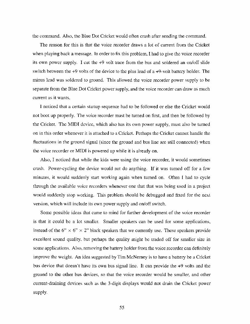
the command. Also, the Blue Dot Cricket would often crash after sending the command.
The reason for this is that the voice recorder draws a lot of current from the Cricket
when playing back a message. In order to fix this problem, I had to give the voice recorder
its own power supply. I cut the +9 volt trace from the bus and soldered an on/off slide
switch between the +9 volts of the device to the plus lead of a +9-volt battery holder. The
minus lead was soldered to ground. This allowed the voice recorder power supply to be
separate from the Blue Dot Cricket power supply, and the voice recorder can draw as much
current as it wants.
I noticed that a certain startup sequence had to be followed or else the Cricket would
not boot up properly. The voice recorder must be turned on first, and then be followed by
the Cricket. The MIDI device, which also has its own power supply, must also be turned
on in this order whenever it is attached to a Cricket. Perhaps the Cricket cannot handle the
fluctuations in the ground signal (since the ground and bus line are still connected) when
the voice recorder or MIDI is powered up while it is already on.
Also, I noticed that while the kids were using the voice recorder, it would sometimes
crash. Power-cycling the device would not do anything. If it was turned off for a few
minutes, it would suddenly start working again when turned on. Often I had to cycle
through the available voice recorders whenever one that that was being used in a project
would suddenly stop working. This problem should be debugged and fixed for the next
version, which will include its own power supply and on/off switch.
Some possible ideas that came to mind for further development of the voice recorder
is that it could be a lot smaller. Smaller speakers can be used for some applications,
instead of the 6" x 6" x 2" black speakers that we currently use. These speakers provide
excellent sound quality, but perhaps the quality might be traded off for smaller size in
some applications. Also, removing the battery holder from the voice recorder can definitely
improve the weight. An idea suggested by Tim McNerney is to have a battery be a Cricket
bus device that doesn't have its own bus signal line. It can provide the +9 volts and the
ground to the other bus devices, so that the voice recorder would be smaller, and other
current-draining devices such as the 3-digit displays would not drain the Cricket power
supply.
55

As for the sound sensor, I was showing Mary and Steve the volume function of the sound
sensor during the workshop, and I noticed that the analog sensitivity knob of the sound
sensor was wired the wrong way. In its current configuration, turning the knob clockwise
gives less sensitivity, and a turn counter-clockwise gives more sensitivity. This should be
revised in the next version.
4.3 Some Comments on Workshop-Based Learning
I learned a number of lessons through the course of this workshop. The first lesson is that
I cannot hold a workshop on my own. It's very hard to work with children. They have
short attention spans and too much energy, and when combined, the result is very chaotic.
It's difficult to keep them focused on the task at hand, and I learned that this alone requires
almost a one-on-one type of relationship with each child. So in order to have a somewhat
productive workshop, plenty of knowledgeable adults need to be at hand to help and mentor
the children. Otherwise, the children become frustrated because they don't receive the help
that they need.
Also, the children should be set up to work in groups. I failed to establish this on the first
day when I gave each child a Cricket of his own. If the children were separated into groups
of two, and were given one computer, one Cricket, and one adult helper, the workshop
would have been much more productive and manageable. In teams of two, the children can
feed off of each other's ideas, fostering more imagination and creativity for their projects.
They could also learn the valuable lesson of sharing and working together.
The format of the workshop I held allowed the children to become more selfish. The
children each expected to have their own laptop or desktop computer. And the children
became selfish with their ideas, too. Towards the end, it seemed as if the children were
accusing each other of copying their ideas.
Organized LEGO parts are very important to the life of the workshop. A lot of time gets
wasted when the children spend a lot of it pouring over the bin looking for a specific part.
Key LEGO parts, mostly the Technic pieces, need to be well sorted and separated from the
usual LEGO bricks. They are the most important parts when building projects requiring
56

LEGO motors.
Also, art supplies should be included as materials for the workshop. They encourage
project creativity, leading children to develop more than just cars for their Cricket projects. I
regret not having plenty of materials for the workshop, but the format made it quite difficult
to have all the materials at hand all the time. The different rooms that we were given for
different days of the workshop took away any sense of a Cricket workshop home, where we
can leave all of our materials lying around and the children's projects can be undisturbed to
be worked on later. Had the workshop been held at the MIT Media Laboratory, where bins
and bins of LEGO bricks are sorted and art supplies are plenty, the workshop would have
had such a different feeling.
One more thing I learned is to always have plenty of ideas for the children before the
workshop. Plenty of project examples encourage the children to dream up their own creative
project ideas. The children really need to see plenty of examples of Cricket use before they
can even begin to think about what the Crickets are capable of. When I showed Mary and
Steve the volume function of the sound sensor, I was not prepared in giving them ideas on
how they could use it. The sensor was then quickly abandoned after the demonstration.
57
Chapter 5
Future Directions
Future versions of the sound sensor and voice recorder can have more functions and capa-
bilities. The software can be expanded to allow these functionalities and more immediate
revisions of the hardware can also be made to improve these devices.
In general, the Cricket technology can benefit from future work on more sound bus
devices. The last section discusses different ideas for integrating more sound-related
technology to the Crickets.
5.1 Future Sound Sensors
For the sound sensor, the previously written tone recognition sensor can be integrated with
the clap and volume functions. The way that the tone recognition program is currently
written, it is only capable of detecting a frequency of 1200 Hz. This can be changed so that
the user can choose from a range of frequencies to be detected, so that the tone recognition
sensor can sense more than just one tone.
Another functionality to the clap sensor might be a clap counter. While Tim McNerney
was working with Gene at the workshop, he noticed that this was the first more advanced
application of the clap sensor that Gene thought of. This function could possibly be done
as a macro in Cricket Logo, or it could be done in the assembly language program of the
sound sensor.
Some revisions that could done to the hardware have been previously mentioned. First,
58
the sensitivity knob can be wired the opposite way so that it follows the conventional rule
of rotation: clockwise for more sensitivity and counter-clockwise for less. Then, if an 8-pin
microprocessor is used, the whole board can be made smaller by placing the components
on both the component and solder sides of the board. All the surface mount components
could be placed on the solder side, for example, cutting down the board size to maybe half
its current size. This board may then be hot-glued to a LEGO part standing on its side, so
as to take less horizontal space.
5.2 Future Voice Recorders
The voice recorder can be expanded so that the Cricket can control more functions. The
"start-record" and "stop-record" bus commands can be implemented. With these new
functions, my opening example of use for the voice recorder pertaining to the Beyond
Black Boxes project can be realized: The voice recorder can be used to record bird chirps
when the Cricket senses that a bird is present.
Revisions that can be made to the board have already been mentioned in the previous
chapters. First, the power supply fix can be permanently added to the hardware, so that
the voice recorder would have its own power supply and on/off switch. Or, the power
supply can be made its own bus device providing power to the other devices as well as the
voice recorder. This power supply can be made efficient so that it is longer-lasting and
yet it remains small. This would allow the shape of the voice recorder to be more two-
dimensional, rather than 3-dimensional with the battery holder. It could then be hot-glued
to a LEGO part, standing sideways, and be a lot less obtrusive to whatever Cricket project
it is used for. With its current size, one can see how much space the voice cricket alone
takes by looking at the picture of Mary's dancing car (see Figure 4.1).
Of course, the most noticeable component of Mary's car is the big black speaker. As
mentioned before, these speakers provide great sound quality, so much that the children
all thought that someone had turned on a radio when Mary would test her car. But size
has become an important issue for me, ever since the workshop was held. The workshop
allowed the devices to be kid-tested, or practically evaluated, and I concluded that the
59

smaller the devices are, the easier they are to incorporate into the Cricket projects. In my
opinion, depending on the Cricket project it is used for, the speakers' sound quality should
be traded for smaller size. If the project is to be mobile, as in Mary's case, smaller speakers
would be more reasonable than great sounding ones. If the project is an installation, as in
a door greeter or an art sculpture, better sound quality would be more appreciated than the
smaller size.
5.3 Ideas for Future Sound Bus Devices
Currently, the Cricket technology supports the clap and volume sensors, and the Cricket
Logo commands beep and note, and the MIDI synthesizer and voice recorder as sound
actuators. In the future, the following sensors and actuators can be developed to expand the
sound capabilities of the Crickets.
Voice recognition device Voice recognition software, like the ones used for hands-free
typing, can be used in making a bus device that is able to take a speech input and
then assemble it to form bus commands that would activate different actuators like
turning on a motor, or turning on the lights in a room. What child or adult would not
find this useful?
Voice synthesis device A commercial voice synthesizer can be used to make a bus
device that would allow children to type the English sentences as an argument to
a Cricket Logo macro, and then have the voice synthesizer say the words when
prompted by the Blue Dot Cricket. This bus device would really encourage children
to build robot-like projects.
Combined voice recorder and synthesis device This combines both types of voice
outputs into one device so that the device can take both oral and written inputs and
be able to say them back under program control.
Combined MIDI synthesizer and voice recorder device This can combine both types
of existing sound outputs for the Cricket technology into one device. The user can
60

program different songs into the MIDI synthesizer and record the vocal part of the
songs into the voice recorder, and be able to output the completed song with vocals
under program control.
61
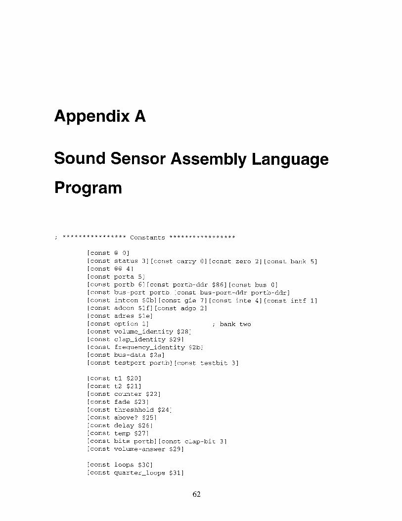
Appendix A
Sound Sensor Assembly Language
Program
; **************** Constants ***************
[const @ 0][const status 3][const carry 0][const zero 2][const bank 5][const @@ 4]
[const porta 51[const portb 6][const portb-ddr $86][const bus 0][const bus-port portb][const bus-port-ddr portb-ddr][const intcon $0b][const gie 7][const inte 4](const intf 1][const adcon $1f][const adgo 2][const adres $1e][const option 1] ; bank two[const volumeidentity $28][const clapidentity $29]
[const frequency-identity $2b)
[const bus-data $2a]
[const testport portb][const testbit 3]
[const tl $20]
[const t2 $21]
[const counter $22]
[const fade $23]
[const threshhold $24]
[const above? $25][const delay $26]
[const temp $27]
[const bits portb][const clap-bit 3]
[const volume-answer $29]
[const loops $30][const quarterloops $31]
62

[const ubtotal $33][const lbtotal $34][const ubtotal_90 $35][const lbtotal_90 $36][const ubanswer $37][const lbanswer $38]
[const int-a $40]
[const int-status $411[const int-phase $42]
; ** Interrupt pointer
[bra start]
[nop][nop][nop]
[bra int-routine]
; **************** Main loop ********************
start
[bsr io-init]loop
[ldan $55][sta adcon]
[bsr conversion]
[lda adres][sta t2][ldan 119][sta counter]
return
[ldan 1][subm counter]
[btss carry status][bra diminish]
[ldan $55][sta adcon]
[bsr conversion]
[lda adres][sta t1]
[lda t1][sub t2] ;t2 - t1[btsc carry status]
[bra return]
[lda t1][sta t2]
[bra return]
diminish
[lda t2][sta fade]
[ror fade][ror fade][ror fade][ldan $1f][andm fade]
[lda fade][subm t2]
[bra store-values]
conversion
[btsc adgo adcon]
[bra conversion]
[rts]
store-values
[lda t2][sta volume-answer]
[sta above?]
[lda threshhold][subm above?] ;t2 - threshhold
63

[btss carry status][bra below]
above [bset clap-bit bits]below [bra loop]
**************** Bus interrupt routine *
int-routine
[bclr gie intcon][sta int-a][lda status][sta int-status][bclr bank status]
[bsr btyi20][btss carry status][bra iret][bsr dispatch][bra iret]
NAME
$68 - green
other sound sensors will be called$69 - blue, $6a for both green and blue
disable interrupts
; store states
dispatch
[lda bus-data][xorn $68][btsc zero status][bra dispatch2][lda bus-data][xorn $6a]
[btsc zero status][bra dispatch2][rts]
is it for green?
is it for green and blue?
if not return
COMMANDS
bsend $168 send bsr $01 -- returns 255 if clap is heard since last querybsend $168 send bsr $02 -- returns a value from 0 to 255 for volumebsend $168 send bsr $03 -- returns 255 if frequency (~1200Hz) is detected
dispatch2
[bsr bus-tyi][lda bus-data][xorn $01] ; is it a clap command?[btsc zero status][bra clap-cmd][lda bus-data][xorn $02] ; is it a volume command?[btsc zero status][bra volume-cmd][lda bus-data][rts]
clap-cmd[btss clap-bit bits][bra return-zero][bclr clap-bit bits]
64

[ldan 255][sta bus-data][bra bus-tyo]
return-zero
[clr bus-data][bra bus-tyo]
volume-cmd
[lda volume-answer][sta bus-data]
[bra bus-tyo]
iret [lda int-status][sta status] ; load states[swap int-a][lswap int-a][bclr intf intcon] clear the interrupt flag[bset gie intcon] ; enable interrupts[rti]
; * * Modified bus transmit and receive codes *
bus-tyi
[btsc bus bus-port][bra bus-tyi]
btyi20 [btss bus bus-port][bra btyi20][ldan 8][sta counter][bsr an-rts]
btyi30 [nop][nop][nop][ror bus-data]
[bclr 7 bus-data][btsc bus bus-port][bset 7 bus-data][decsz counter][bra btyi30][bsr an-rts][nop][bset carry status][btsc bus bus-port][bclr carry status]
an-rts [rts]
bus-tyo
[ldan bus-port-ddr][sta @@][bclr bus bus-port][bclr bus @][ldan 33][sta counter]
btyo20 [decsz counter]
[bra btyo20]
[bset bus bus-port][ldan 9][sta counter][bsr an-rts][nop][nop]
btyo50 [ror bus-data]
[bclr bus bus-port][btsc carry status][bset bus bus-port]
65

[nop][nop][nop]
[decsz counter]
[bra btyo50]
[nop][nop]
[bset bus @]
[rts]
;** * Initialization code *
io-init[bset bank status]
[clr adcon]
[bclr testbit testport]
[ldan $bf][sta option] set int on falling edge of RBO/INT pin[bclr bank status]
[bclr testbit testport]
[bclr clap-bit bits][ldan $40][sta threshhold]
[clr delay]
[ldan 60][sta counter]
ioin20 [clra][bsr delay-loop]
[decsz counter][bra ioin20]
[bset inte intcon] enable RB0/INT interrupt
[bset gie intcon]
[rts]
delay-loop
[addn -1][btss zero status][bra delayloop]
[rts]
66

Appendix B
Voice Recorder Assembly Language
Program
;****************** Constants ***************************
pic registers
[const @ 01
[const timer 1]
[const pcl 2]
[const status 3]
[const c 0][const z 2][const bank2 5]
[const @@ 41
[const porta 51[const porta-ddr $85]
[const portb 6][const portb-ddr $86]
[const eedata 8]
[const eeadr 9]
[const intcon $0b]
[const gie 7][const tOie 5][const inte
[const intf 1][const tOif 2]
option 1] ; bank two
eeconl 8][const eerd 0][const eewr
eecon2 9]1][const wren 2]
[const counter $Oc] ; bit counter for byte in process[const bus-data $Od]
[const identity $Oe]
[const rename-count $0f][const tO $10] ; timers[const nthmsg $11]
[const bits $12]
[const eombit 0] [const busffbit 1] [const resetbit 2]
[const ffbit 3][const pnbit 4][const pn2bit 5][const int-a $13]
67
[const[const[const
4]
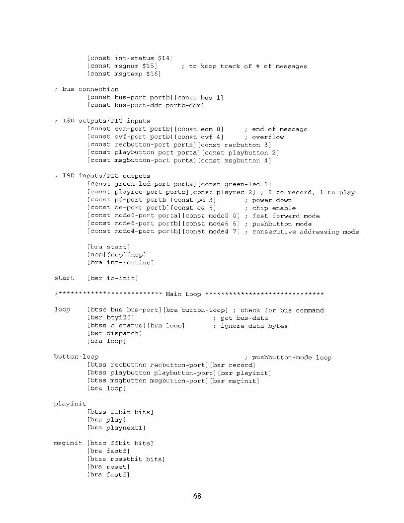
[const int-status $14][const msgnum $15] ; to keep track of # of messages
[const msgtemp $16]
bus connection
[const bus-port portb][const bus 1]
[const bus-port-ddr portb-ddr]
ISD outputs/PIC inputs
[const eom-port portb][const eom 0] ; end of message
[const ovf-port portb][const ovf 4] ; overflow
[const recbutton-port porta][const recbutton 3][const playbutton-port porta][const playbutton 2]
[const msgbutton-port porta][const msgbutton 4]
ISD inputs/PIC outputs
[const green-led-port portal[const green-led 1]
[const playrec-port portb][const playrec 2] ; 0 to record, 1 to play[const pd-port portb][const pd 3] ; power down[const ce-port portb][const ce 5] ; chip enable[const modeG-port portal[const mode0 0] ; fast forward mode[const mode6-port portb][const mode6 6] ; pushbutton mode[const mode4-port portb][const mode4 7] ; consecutive addressing mode
[bra start]
[nop][nop][nop]
[bra int-routine]
start [bsr io-init]
;****************** Main Loop ******************************
loop [btsc bus bus-port][bra button-loop] ; check for bus command
[bsr btyi20] ; get bus-data
[btss c status][bra loop] ; ignore data bytes
[bsr dispatch]
[bra loop]
button-loop ; pushbutton-mode loop[btss recbutton recbutton-port][bsr record]
[btss playbutton playbutton-port][bsr playinit]
[btss msgbutton msgbutton-port][bsr msginit]
[bra loop]
playinit
[btss ffbit bits][bra play]
[bra playnextl]
msginit [btsc ffbit bits]
[bra fastf]
[btss resetbit bits][bra reset]
[bra fastf]
68

NAME
$54 - red
3 other voice recorders will be called
$55 (blue), $56 (yellow), and $57 (white)
COMMANDS
bsend $154 bsend $nn -- play nn'th message
dispatch
[lda bus-data]
[xorn $54] ; is it for me?
[btss z status][rts]
[bsr bus-tyi]
[lda bus-data]
[xorn $ff]
[btsc z status][bra record-from-beginning]
playnnth
[lda bus-data] ; otherwise store nn
[sta nthmsg]
[bset pd pd-port][bclr pd pd-port] ; reset chip
[bclr resetbit bits]
[bclr ffbit bits][btsc pnbit bits][bsr resetmodes]
[bset playrec playrec-port] ; set to play
[dec nthmsg] subtract one from nthmsg so code will workff? [lda nthmsg]
[btsc z status][bra playnext2]
[bset busffbit bits]
[bsr fastf2]
[bclr busffbit bits]
[dec nthmsg]
[bra ff?]
record-from-beginning
[clr msgnum]
[clr eedata]
[bset bank2 status]
[bset wren eeconl]
[ldan $55][sta eecon2]
[ldan $aa][sta eecon2]
[bset eewr eeconl]
[bclr wren eeconl]
[bclr bank2 status]
[rts]
PUSH-BUTTON MODE
play button will play current message.
on power-up, play button will play first message.record button must be held down while recording the entire message.record will put message at the end of the previously recorded messages.msg# will reset if pressed once.msg# will fastforward to the 2nd message if pressed twice.to the 3rd, if pressed three times, and so on.
69

; press play to hear that message.; pressing record after fastforwarding will reset.
RECORDING -- FOR PUSH-BUTTON MODE ONLY
record is for recording the 1st messagerecord2 is for recording subsequent messages, requiring fast-forward modewaitrec is the loop that waits until the message being recorded is donerecovf is for when the end of the address space is reached while recording
*********************** Recording Sequence
record [ldan $ff][bsr delay-loop]; wait about 1 msec to avoid switch bounce[bclr resetbit bits]
[bclr pnbit bits][bclr ffbit bits][lda msgnum]
[btss z status][bra record2]
[bset pd pd-port][bclr pd pd-port]
[bclr playrec playrec-port]
[bset mode4 mode4-port]
[bset mode6 mode6-port]
[bclr green-led green-led-port]
[bclr ce ce-port][bset ce ce-port] ; pulse ce low to start recowaitrec [btss ovf ovf-port][bra recovf]
[btss recbutton recbutton-port] ; loop until button is no longer low[bra waitrec]
[ldan $ff][bsr delay-loop]; wait about 1 msec to avoid switch bouncerecovf [bclr ce ce-port][bset ce ce-port] ; pulse ce low to stop recor
[bsr write-msgnum]
[bclr mode4 mode4-port]
[bset playrec playrec-port]
[bset green-led green-led-port]
[rts] ; go back to start loop
record2 [bset pd pd-port]
[bset mode4 mode4-port]
[bset mode6 mode6-port]
[bclr pd pd-port]
[bset playrec playrec-port]
[bset mode0 modeO-port]
[lda msgnum][sta msgtemp]
recff [bclr ce ce-port][bset ce ce-port]
[bclr intf intcon][bset inte intcon]
[bset gie intcon]
ffloop2 [btss eombit bits][bra ffloop2][bclr gie intcon]
[bclr inte intcon]
[bclr eombit bits]
[decsz msgtemp][bra recff]
[bclr mode0 modeG-port][bclr playrec playrec-port]
[bclr green-led green-led-port]
[bclr ce ce-port][bset ce ce-port]
; wait for eom interrupt
70
rd
d
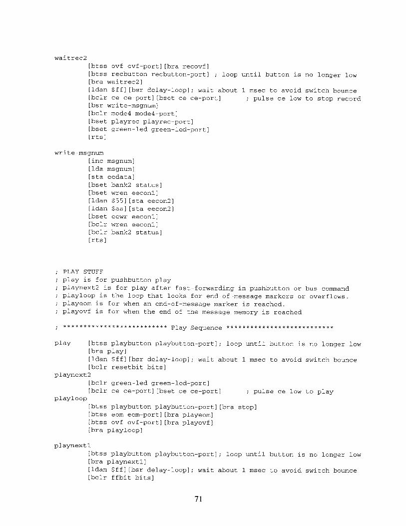
waitrec2
[btss ovf ovf-port][bra recovf][btss recbutton recbutton-port] ; loop until button is no longer low[bra waitrec2][ldan $ff][bsr delay-loop]; wait about 1 msec to avoid switch bounce[bclr ce ce-port][bset ce ce-port] ; pulse ce low to stop record[bsr write-msgnum][bclr mode4 mode4-port][bset playrec playrec-port][bset green-led green-led-port][rts]
write-msgnum
[inc msgnum][lda msgnum]
[sta eedata]
[bset bank2 status][bset wren eeconl][ldan $55][sta eecon2][ldan $aa][sta eecon2][bset eewr eeconl][bclr wren eeconl][bclr bank2 status][rts]
PLAY STUFF
play is for pushbutton playplaynext2 is for play after fast-forwarding in pushbutton or bus commandplayloop is the loop that looks for end-of-message markers or overflows.playeom is for when an end-of-message marker is reached.playovf is for when the end of the message memory is reached
************************** Play Sequence ***************************
play [btss playbutton playbutton-port]; loop until button is no longer low[bra play][ldan $ff][bsr delay-loop]; wait about 1 msec to avoid switch bounce[bclr resetbit bits]
playnext2
[bclr green-led green-led-port][bclr ce ce-port][bset ce ce-port] ; pulse ce low to play
playloop
[btss playbutton playbutton-port][bra stop][btss eom eom-port][bra playeom][btss ovf ovf-port][bra playovf][bra playloop]
playnext1
[btss playbutton playbutton-port]; loop until button is no longer low[bra playnext1]
[ldan $ff][bsr delay-loop]; wait about 1 msec to avoid switch bounce[bclr ffbit bits]
71
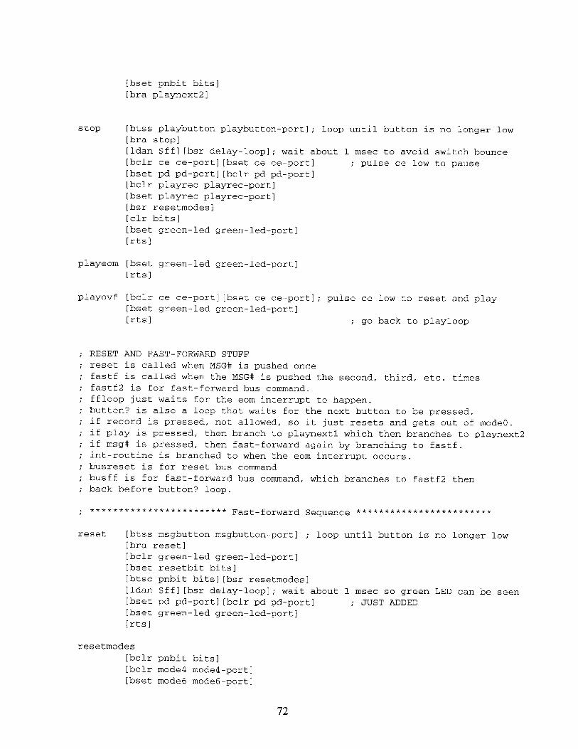
[bset pnbit bits][bra playnext2]
stop [btss playbutton playbutton-port]; loop until button is no longer low[bra stop]
[ldan $ff][bsr delay-loop]; wait about 1 msec to avoid switch bounce[bclr ce ce-port][bset ce ce-port] ; pulse ce low to pause
[bset pd pd-port][bclr pd pd-port)
[bclr playrec playrec-port]
[bset playrec playrec-port]
[bsr resetmodes]
[clr bits]
[bset green-led green-led-port]
[rts]
playeom [bset green-led green-led-port]
[rts]
playovf [bclr ce ce-port][bset ce ce-port]; pulse ce low to reset and play[bset green-led green-led-port]
[rts] ; go back to playloop
RESET AND FAST-FORWARD STUFF
reset is called when MSG# is pushed once
fastf is called when the MSG# is pushed the second, third, etc. timesfastf2 is for fast-forward bus command.ffloop just waits for the eom interrupt to happen.
button? is also a loop that waits for the next button to be pressed.
if record is pressed, not allowed, so it just resets and gets out of mode0.if play is pressed, then branch to playnextl which then branches to playnext2if msg# is pressed, then fast-forward again by branching to fastf.int-routine is branched to when the eom interrupt occurs.
busreset is for reset bus commandbusff is for fast-forward bus command, which branches to fastf2 thenback before button? loop.
************************ Fast-forward Sequence ************************
reset [btss msgbutton msgbutton-port] ; loop until button is no longer low[bra reset]
[bclr green-led green-led-port]
[bset resetbit bits]
[btsc pnbit bits][bsr resetmodes]
[ldan $ff][bsr delay-loop]; wait about 1 msec so green LED can be seen[bset pd pd-port][bclr pd pd-port] ; JUST ADDED
[bset green-led green-led-port]
[rts]
resetmodes
[bclr pnbit bits][bclr mode4 mode4-port]
[bset mode6 mode6-port]
72

[rts]
fastf [bclr resetbit bits][bclr green-led green-led-port]
fastfl [btss msgbutton msgbutton-port] ; loop until button is no longer low
[bra fastfl]
fastf2 [bclr mode6 mode6-port] branch here if bus command[bset mode4 mode4-port] ; disable mode6 and enable mode0[bset modeG mode0-port]
[bclr ce ce-port][bset ce ce-port] ; pulse ce
[bclr intf intcon]
[bset inte intcon]
[bset gie intcon]
ffloop [btss eombit bits][bra ffloop] ; wait for eom interrupt[bclr gie intcon]
[bclr inte intcon]
[bclr eombit bits]
[bclr mode0 mode0-port]
[bset green-led green-led-port]
[btsc busffbit bits][rts] end here if play nnth command
[bset ffbit bits]
[rts]
INTERRUPT STUFF
one kind of interrupt -- RBO
int-routine
[bclr intf intcon]
[bset eombit bits]
[rti]
; for rb0/int interrupt
BUS STUFF
the form of a byte is100 usec low time (to allow for interupt latency)
start bit(l) + 8 data bits + stop bit (0 for cmnd 1 for data)each bit is exactly 10 usec long. The bits should be sampled in themiddle (this code samples between 4 and 7 usec in)
return a byte in bus data
also return the inverse of the stop bit in the carry
commands have a 0 stop bit -> carry set
data has a 1 stop bit -> carry clear
************************** Bus Handling ************************
bus-tyi [btsc bus bus-port][bra bus-tyi]btyi20 [btss bus bus-port][bra btyi20]
[ldan 8][sta counter][bsr an-rts]
btyi30 [nop][nop][nop]
[ror bus-data][bclr 7 bus-data]
[btsc bus bus-port]
; for for sync edge
73

[bset 7 bus-data][decsz counter]
[bra btyi30][bsr an-rts][nop][bset c status][btsc bus bus-port][bclr c status]
an-rts [rts]; no stop bit -> carry clear
; send a byte down the bus. the stop; of a data byte
; input in bus-databus-tyo [ldan bus-port-ddr][sta @@]
[bclr bus bus-port][bclr bus[ldan 33][bsr delay-loop]
btyo20 [decsz counter][bra btyo20][bset bus bus-port][ldan 9][sta counter][bsr an-rts][nop][nop]
btyo50 [ror bus-data]
[bclr bus bus-port][btsc c status]
[bset bus bus-port][nop][nop][nop][decsz counter]
[bra btyo50][nop][nop]
[bset bus @][rts]
bit is always 0
@]
; give receiver a chance to sync
start bit
bit -> carry
; delay for a*4 usec
delay-loop
[addn -1]
[btss z status]
[bra delay-loop]
[rts]
io-init [clr eeadr]set data direction bits
[bset bank2 status][bset eerd eeconl][bclr green-led green-led-port][bclr playrec playrec-port][bclr pd pd-port][bclr ce ce-port][bclr mode0 modeG-port][bclr mode4 mode4-port][bclr mode6 mode6-port][bset eom eom-port][bset ovf ovf-port][bset recbutton recbutton-port][bset playbutton playbutton-port][bset msgbutton msgbutton-port][ldan $87][sta option][bclr bank2 status]
; identity is at ee addr 0
set TMRO to / 256 = 3.9 Hz
74
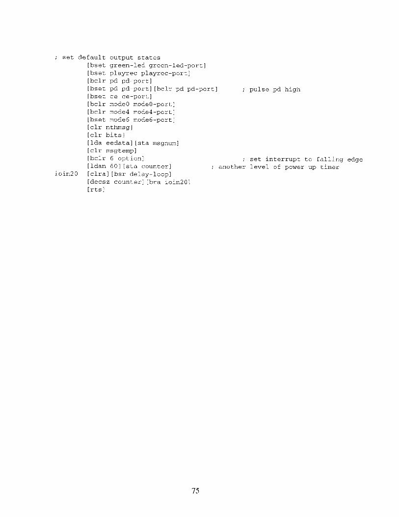
set default output states
[bset green-led green-led-port]
[bset playrec playrec-port]
[bclr pd pd-port][bset pd pd-port][bclr pd pd-por
[bset ce ce-port]
[bclr mode0 mode0-port]
[bclr mode4 mode4-port]
[bset mode6 mode6-port]
[clr nthmsg]
[clr bits][lda eedata][sta msgnum]
[clr msgtemp]
[bclr 6 option]
[ldan 60][sta counter]
ioin20 [clra][bsr delay-loop][decsz counter][bra ioin20]
[rts]
; pulse pd high
; set interrupt to falling edge
another level of power up timer
75
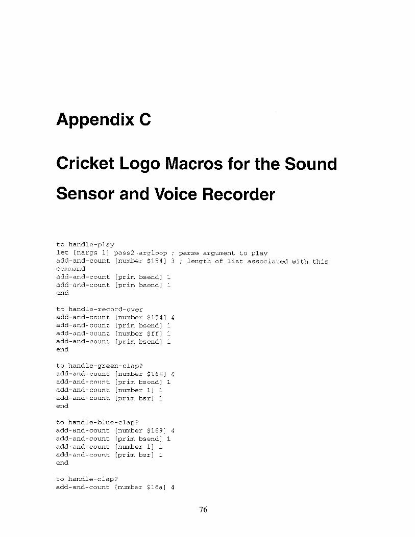
Appendix C
Cricket Logo Macros for the Sound
Sensor and Voice Recorder
to handle-play
let [nargs 1] pass2-argloop ; parse argument to playadd-and-count [number $154] 3 ; length of list associated with thiscommand
add-and-count [prim bsend] 1
add-and-count [prim bsend] 1end
to handle-record-over
add-and-count [number $154] 4
add-and-count [prim bsend] 1
add-and-count [number $ff] 1
add-and-count [prim bsend] 1
end
to handle-green-clap?
add-and-count [number $168] 4
add-and-count [prim bsend] 1
add-and-count [number 1] 1
add-and-count [prim bsr] 1
end
to handle-blue-clap?
add-and-count [number $169] 4add-and-count [prim bsend] 1
add-and-count [number 1] 1
add-and-count [prim bsr] 1
end
to handle-clap?
add-and-count [number $16a] 4
76

add-and-count [prim bsend] 1add-and-count [number 1] 1add-and-count [prim bsr] 1end
to handle-green-volume?
add-and-count [number $1681 4add-and-count [prim bsend] 1add-and-count [number 2] 1add-and-count [prim bsr] 1end
to handle-blue-volume?add-and-count [number $169] 4add-and-count [prim bsend] 1add-and-count [number 2] 1add-and-count [prim bsr] 1end
to handle-volume?
add-and-count [number $16a] 4add-and-count [prim bsend] 1add-and-count [number 2] 1add-and-count [prim bsr] 1end
to setup
setup-specials [( ) ... play record-over green-clap? blue-clap? clap?green-volume? blue-volume? volume?]put "|(| "outputs? "true put ") "outputs? "false
put "play "outputs? "falseput "record-over "outputs? "falseput "green-clap? "outputs? "trueput "blue-clap? "outputs? "trueput "clap? "outputs? "trueput "green-volume? "outputs? "trueput "blue-volume? "outputs? "trueput "volume? "outputs? "trueend
77

Bibliography
[1] Thomas C. Hayes and Paul Horowitz. Student Manual for The Art of Electronics.
Cambridge University Press, 1989.
[2] http://fredm.www.media.mit.edu/people/fredm/projects/cricket/types.html.
[3] http://lcs.www.media.mit.edu/people/fredm/projects/cricket/.
[4] Information Storage Devices. ISD Data Book: Voice Record and Playback ICs, 1996.
[5] Fred G. Martin. Children, cybernetics, and programmable turtles. Master's thesis,
The Massachusetts Institute of Technology, MIT Media Laboratory, 20 Ames Street
Room E15-315, Cambridge, MA 02139, 1988.
[6] Fred G. Martin. Kids learning engineering science using LEGO and the programmable
brick. Prepared for the 1996 meeting of the American Educational Research Associ-
ation, April 1996.
[7] Microchip Technology. PIC16C71X: 8-bit CMOS Microcontrollers with A/D Con-
verter, 1997.
[8] Microchip Technology. PIC16F8X: 18-pin Flash/EEPROM 8-bit Microcontrollers,
1998.
[9] National Semiconductor. LM386 Low Voltage Audio Power Amplifier, September
1997.
[10] Seymour Papert. The Children's Machine: Rethinking School in the Age of the
Computer. Basic Books, New York, 1993.
78
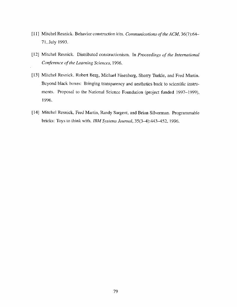
[11] Mitchel Resnick. Behavior construction kits. Communications of the ACM, 36(7):64-
71, July 1993.
[12] Mitchel Resnick. Distributed constructionism. In Proceedings of the International
Conference of the Learning Sciences, 1996.
[13] Mitchel Resnick, Robert Berg, Michael Eisenberg, Sherry Turkle, and Fred Martin.
Beyond black boxes: Bringing transparency and aesthetics back to scientific instru-
ments. Proposal to the National Science Foundation (project funded 1997-1999),
1996.
[14] Mitchel Resnick, Fred Martin, Randy Sargent, and Brian Silverman. Programmable
bricks: Toys to think with. IBM Systems Journal, 35(3-4):443-452, 1996.
79