Embed Size (px)
Citation preview
CAUTION
Do not operate the equipment before you have read and understood the instructions for use.
OWNER’S AND OPERATORS MANUAL
DGA50C
DGA50C
X750-023 80 1 X750801-250 3
Table of Contents Page 1. Safety Guidelines 2. Specifications 2-1. Data 2-2. Ambient Condition 3. Use 4. Parts 4-1. Outer and Main Components 4-2. Operation Panel 4-3. Output Panel 5. Equipment 5-1. Monitor Lamp 5-2. Meters 5-3. Fuel Line Changeover Valve
(3-Way Valve) 6. Transportation & Installation 6-1. How to transport 6-2. Installation 7. Connecting load 7-1. Select Load Cable 7-2. Connecting Load Cable 7-3. ELCB and Grounding 8. Initialization and Pre-check 8-1. Engine Oil 8-2. Coolant / Water 8-3. Fan Belt 8-4. Fuel 8-5. Fuel, Oil and Coolant Leakage 8-6. Battery 9. Operation 9-1. Initialization and Preparation 9-2. During Operation 9-3. Stopping 9-4. Protection Feature 9-5. Connect to External Fuel Tank 10. Check and Maintenance 11. Long Term Storage 12. Troubleshooting 13. Generator Circuit Diagram 14. Engine Circuit Diagram
1 5 5 6 6 6 6 7 8 9 9
11 16 17 17 18 19 19 20 21 24 24 25 27 27 28 28 30 30 32 33 33 34
35 43 44 47 48
SOUND-PROOF
DIESEL ENGINE GENERATOR

1
Introduction
Thank you for purchasing Shindaiwa Sound Proof Diesel Engine Generator.
This user manual was created to ensure the safe operation of this equipment.
Therefore, the manufacturer of this equipment strongly recommends that the user
follow the instructions herein, to avoid unnecessary accidents and repairs.
Please operate this equipment after thoroughly reviewing and understanding the
contents of this manual.
Please attach this manual, if the equipment will be sub-leased.
Please store this manual near the equipment for easy reference.
Following convention will be used throughout the ma nual to indicate the degree of cautions.
Danger Can cause serious injuries or death.
Caution
Can cause minor injuries or damage to the equipment or other properties.
<Caution> Other types of caution
Even some of the items noted in『 Caution 』may lead to serious injuries.
Please read all item and follow all the safety guidelines.
Danger : Suffocation from exhaust fume Exhaust fume from the engine contains many elements harmful to
human. Do not operate this equipment in poorly ventilated area, such as
inside a room or in a tunnel.
Danger : Electric Shock Do not insert metal objects (such as pin or wire) into plug-in receptacles.
Do not touch wiring or electric parts inside the equipment during
operation.
Ground the every grounding terminal to the earth as set in the manual. If
even one of all is unconnected by mistake or accident, it will be much
more dangerous for human than the NO-RELAY case, because leaking
current inevitably goes through the body.
Even when the ELCB in the load is grounded to the earth, be sure to
connect the terminal of bonnet in the equipment.
Be sure to check the resistor value of the equipment periodically so that
you can avoid the electric shock caused by electric leakage
Before connecting or disconnecting a load cable from output receptacles,
always turn the circuit breaker to OFF position.
1 Safety Guidelines
2
Before performing any equipment check or maintenance, stop the
engine, and remove the engine key. A person performing the
maintenance should always keep the key.
Danger : Injuries
Close all doors and place locks during operating this equipment, to avoid
injuries by unintentionally touching cooling fan and fan belt.
Caution : Suffocation from exhausting fume Do not point the exhaust fume toward pedestrians or building.
Caution : Injuries to eye and skin Battery fluid contains diluted sulfuric acid. Avoid contact with eyes, skin
or on clothing. If the acid comes in contact, especially with eyes, flush
with a lot of water, and contact your physician immediately.
Caution : Explosion Do not use the equipment or charge the battery, in the case the battery
fluid level is lower than the LOWER level.
Battery may emit some combustible gas, so keep it away from fire and
sparks.
Caution : Fire The equipment uses Diesel Oil as a fuel. When refueling, always stop
the engine and keep away from fire. Moreover, always wait until the
engine cools down before refueling.
Always wipe any drip of Diesel fuel or lubrication oil. Do not use this
equipment when a leak is found. Repair the equipment before use.
Temperature around muffler and exhaust can get extremely high. Keep
any inflammable items (such as fuel, gas, paint, etc.) away from the
equipment.
Always operate this equipment on flat surface and, at least 1 meter away
from any objects (wall, box, etc.).
Do not connect AC output to any indoor wiring.
Always wait until the equipment cools down, before placing any covering
materials for storage.
Caution : Burns Never open the radiator cap during operation or just after engine stops
as hot vapor may belch out.
Do not touch the engine and muffler during operation and immediately
after stopping the equipment, for the temperature can reach extremely
high.
3
When checking engine oil or changing oil, always stop the engine, and
wait until the engine cools down. If you open either the oil gauge or the
oil plug during operation, hot oil may cause some injury.
Caution : Injuries When lifting the equipment, always use a lift hook. Do not lift a handle,
for it may cause equipment to drop due to handle breaking off.
Always place the equipment on a flat and stable surface, to keep the
equipment from sliding.
When starting the engine, turn off the connected equipment and set the
circuit breaker to OFF position.
Do not move the equipment during operation.
When performing equipment check and maintenance, always stop the
engine.
Do not operate the equipment, if the equipment is being modified or if
the parts are removed.
4
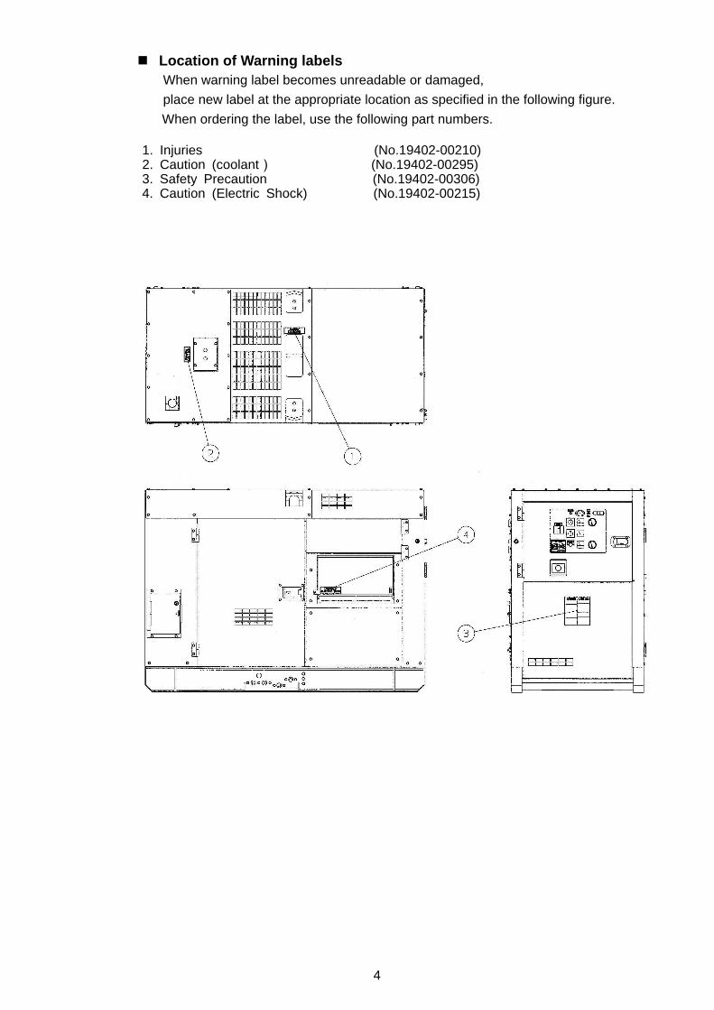
Location of Warning labels When warning label becomes unreadable or damaged,
place new label at the appropriate location as specified in the following figure.
When ordering the label, use the following part numbers.
1. Injuries (No.19402-00210) 2. Caution (coolant) (No.19402-00295)
3. Safety Precaution (No.19402-00306) 4. Caution (Electric Shock) (No.19402-00215)
5
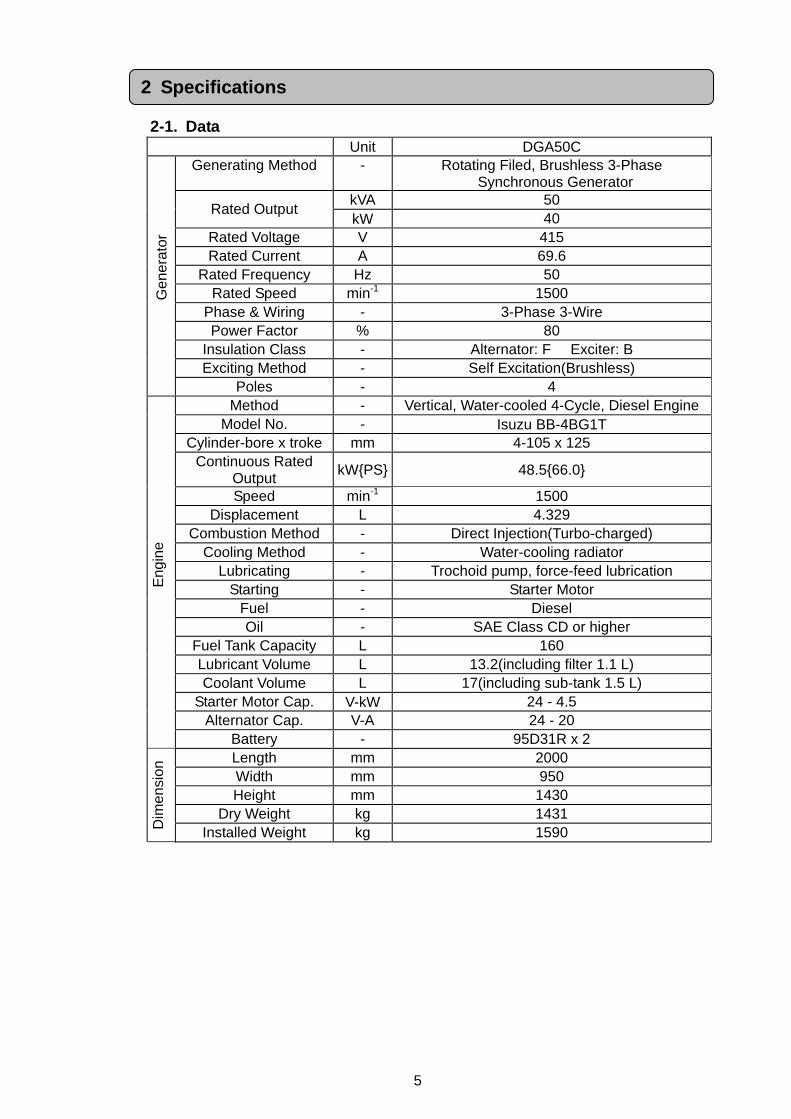
2-1. Data
Unit DGA50C Generating Method - Rotating Filed, Brushless 3-Phase
Synchronous Generator kVA 50
Rated Output kW 40
Rated Voltage V 415 Rated Current A 69.6
Rated Frequency Hz 50 Rated Speed min-1 1500
Phase & Wiring - 3-Phase 3-Wire Power Factor % 80
Insulation Class - Alternator: F Exciter: B Exciting Method - Self Excitation(Brushless)
Gen
erat
or
Poles - 4 Method - Vertical, Water-cooled 4-Cycle, Diesel Engine
Model No. - Isuzu BB-4BG1T Cylinder-bore x troke mm 4-105 x 125
Continuous Rated Output
kWPS 48.566.0
Speed min-1 1500 Displacement L 4.329
Combustion Method - Direct Injection(Turbo-charged) Cooling Method - Water-cooling radiator
Lubricating - Trochoid pump, force-feed lubrication Starting - Starter Motor
Fuel - Diesel Oil - SAE Class CD or higher
Fuel Tank Capacity L 160 Lubricant Volume L 13.2(including filter 1.1 L) Coolant Volume L 17(including sub-tank 1.5 L)
Starter Motor Cap. V-kW 24 - 4.5 Alternator Cap. V-A 24 - 20
Eng
ine
Battery - 95D31R x 2 Length mm 2000 Width mm 950 Height mm 1430
Dry Weight kg 1431
Dim
ensi
on
Installed Weight kg 1590
2 Specifications
6
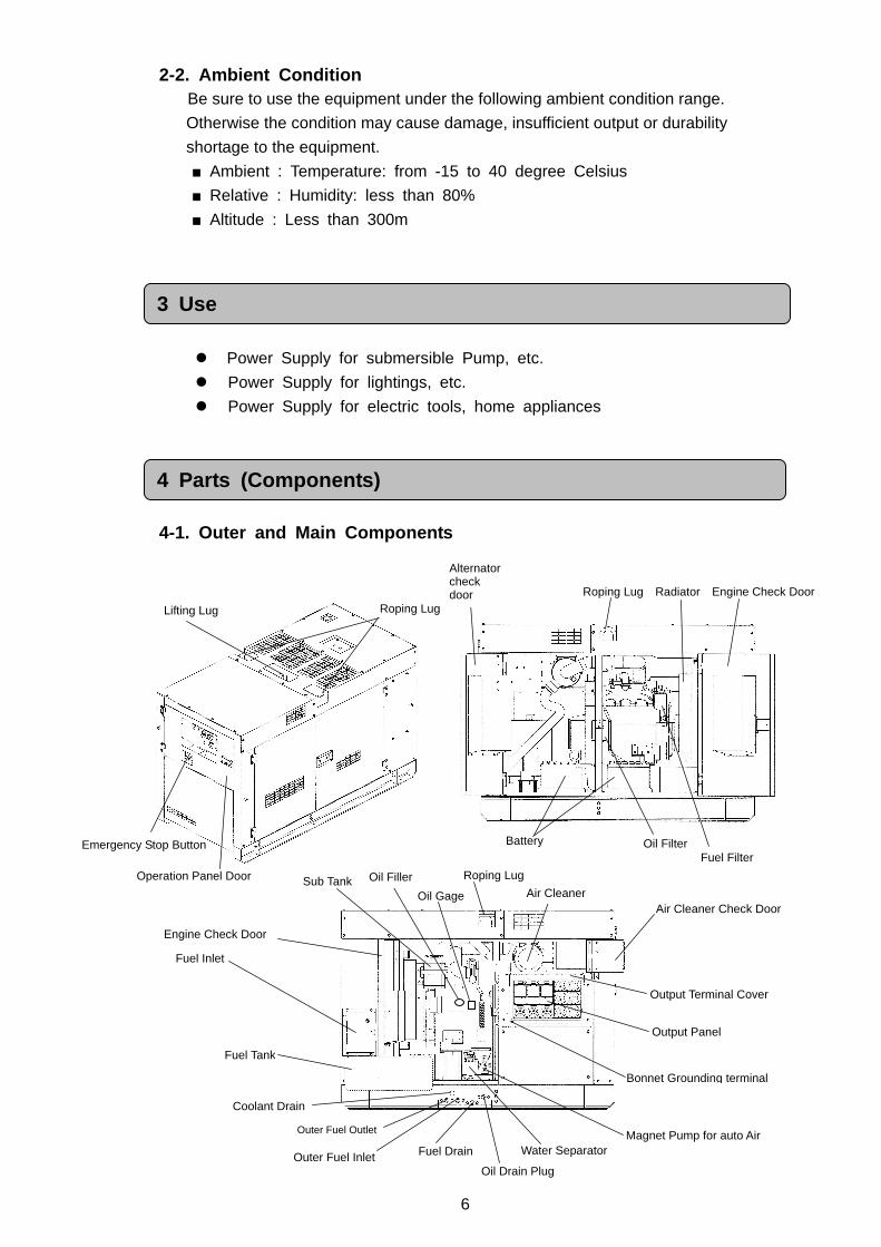
Fuel Filter Oil Filter
Roping Lug Radiator Engine Check Door
Battery
Alternator check door
2-2. Ambient Condition Be sure to use the equipment under the following ambient condition range.
Otherwise the condition may cause damage, insufficient output or durability
shortage to the equipment.
Ambient : Temperature: from -15 to 40 degree Celsius
Relative : Humidity: less than 80%
Altitude : Less than 300m
Power Supply for submersible Pump, etc.
Power Supply for lightings, etc.
Power Supply for electric tools, home appliances
4-1. Outer and Main Components
3 Use
4 Parts (Components)
Roping Lug Lifting Lug
Operation Panel Door
Emergency Stop Button
Coolant Drain
Roping Lug
Oil Drain Plug
Engine Check Door
Fuel Inlet
Air Cleaner Check Door
Sub Tank
Output Terminal Cover
Fuel Tank
Fuel Drain Water Separator
Oil Gage
Outer Fuel Inlet
Outer Fuel Outlet
Output Panel
Magnet Pump for auto Air
Oil Filler Air Cleaner
Bonnet Grounding terminal
7
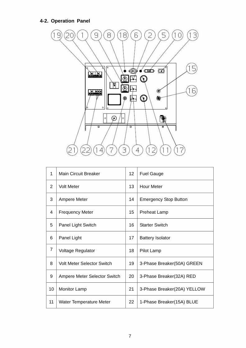
4-2. Operation Panel
1 Main Circuit Breaker 12 Fuel Gauge
2 Volt Meter 13 Hour Meter
3 Ampere Meter 14 Emergency Stop Button
4 Frequency Meter 15 Preheat Lamp
5 Panel Light Switch 16 Starter Switch
6 Panel Light 17 Battery Isolator
7
Voltage Regulator
18 Pilot Lamp
8 Volt Meter Selector Switch 19 3-Phase Breaker(50A) GREEN
9 Ampere Meter Selector Switch 20 3-Phase Breaker(32A) RED
10 Monitor Lamp 21 3-Phase Breaker(20A) YELLOW
11 Water Temperature Meter 22 1-Phase Breaker(15A) BLUE
8
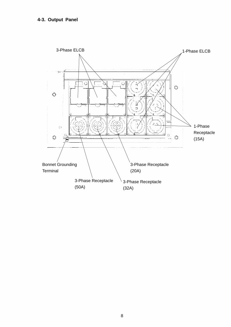
4-3. Output Panel
3-Phase ELCB 1-Phase ELCB
1-Phase
Receptacle
(15A)
3-Phase Receptacle
(50A)
3-Phase Receptacle
(20A)
3-Phase Receptacle
(32A)
Bonnet Grounding
Terminal
9
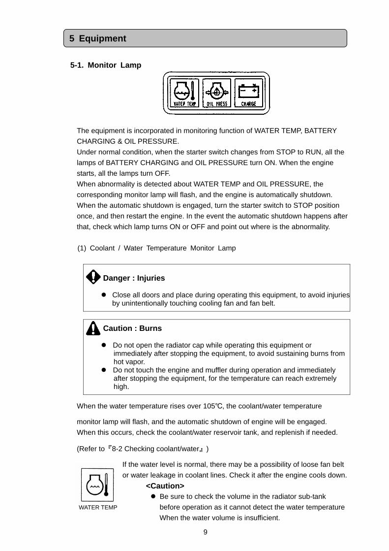
5-1. Monitor Lamp
The equipment is incorporated in monitoring function of WATER TEMP, BATTERY
CHARGING & OIL PRESSURE.
Under normal condition, when the starter switch changes from STOP to RUN, all the
lamps of BATTERY CHARGING and OIL PRESSURE turn ON. When the engine
starts, all the lamps turn OFF.
When abnormality is detected about WATER TEMP and OIL PRESSURE, the
corresponding monitor lamp will flash, and the engine is automatically shutdown.
When the automatic shutdown is engaged, turn the starter switch to STOP position
once, and then restart the engine. In the event the automatic shutdown happens after
that, check which lamp turns ON or OFF and point out where is the abnormality.
(1) Coolant / Water Temperature Monitor Lamp
Caution : Burns Do not open the radiator cap while operating this equipment or
immediately after stopping the equipment, to avoid sustaining burns from hot vapor.
Do not touch the engine and muffler during operation and immediately after stopping the equipment, for the temperature can reach extremely high.
When the water temperature rises over 105, the coolant/water temperature
monitor lamp will flash, and the automatic shutdown of engine will be engaged.
When this occurs, check the coolant/water reservoir tank, and replenish if needed.
(Refer to『8-2 Checking coolant/water』)
If the water level is normal, there may be a possibility of loose fan belt
or water leakage in coolant lines. Check it after the engine cools down.
<Caution> Be sure to check the volume in the radiator sub-tank
before operation as it cannot detect the water temperature
When the water volume is insufficient.
Danger : Injuries
Close all doors and place during operating this equipment, to avoid injuries
by unintentionally touching cooling fan and fan belt.
5 Equipment
WATER TEMP
10
(2) Oil Pressure Monitor Lamp (Low Oil Pressure)
Danger : Injuries
Close all doors and place during operating this equipment, to avoid injuries by unintentionally touching cooling fan and fan belt.
Caution: Burns
Do not touch the engine and muffler during operation and immediately after stopping the equipment, for the temperature can reach extremely high.
Do not open the radiator cap while operating this equipment or immediately after stopping the equipment, to avoid sustaining burns from hot vapor.
When checking engine oil or changing oil, always stop the engine, and wait until the engine cools down. If you open either the oil gauge or the oil plug during operation, hot oil may cause some injury.
When the engine oil pressure drops below 0.98 x 100kPa 1kgf/cm2
during operation, the oil pressure monitor lamp will flash, and the
automatic shutdown will be engaged.
When this occurs, check the engine oil level, and replenish to the
maximum level if needed.
<Caution> The engine oil pressure monitor cannot detect the degradation of engine oil
itself. Please check the engine oil periodically, and change if needed. (Refer to 『8-1. Checking engine oil』)
(3) Battery Charge Monitor Lamp (Charging Lamp)
When the battery turns unable to be charged during operation, the
battery charge monitor lamp will flash. In the event this occurs, stop
the engine consult with the authorized distributor or our
engineering section.
<Caution> The battery charge monitor cannot detect the degradation of the battery
nor the battery fluid level. Check the battery fluid level periodically. (Refer to『8-6. Checking Battery』)
OIL PRESS
CHARGE
11
5-2. Meters
(1) Hour Meter
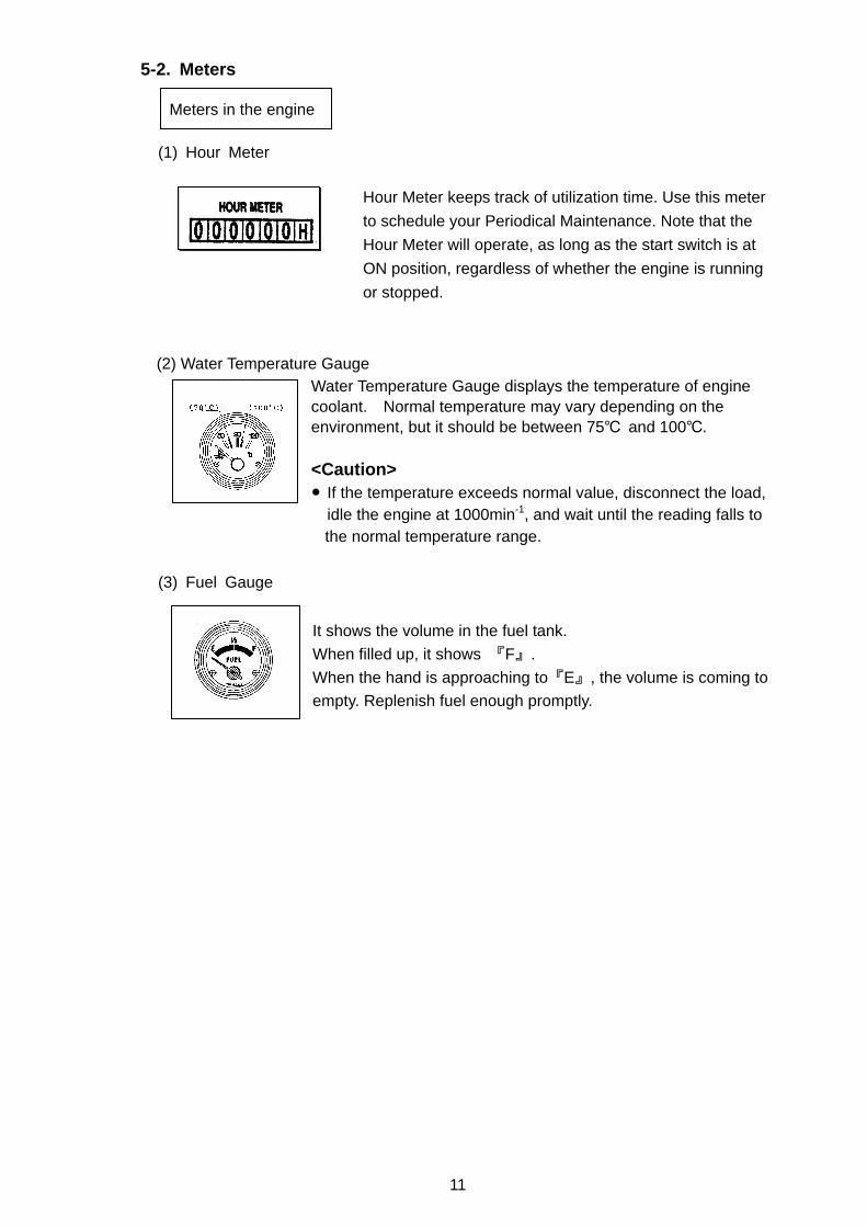
Hour Meter keeps track of utilization time. Use this meter
to schedule your Periodical Maintenance. Note that the
Hour Meter will operate, as long as the start switch is at
ON position, regardless of whether the engine is running
or stopped.
(2) Water Temperature Gauge Water Temperature Gauge displays the temperature of engine coolant. Normal temperature may vary depending on the environment, but it should be between 75 and 100. <Caution> If the temperature exceeds normal value, disconnect the load,
idle the engine at 1000min-1, and wait until the reading falls to the normal temperature range.
(3) Fuel Gauge
It shows the volume in the fuel tank.
When filled up, it shows 『F』.
When the hand is approaching to『E』, the volume is coming to
empty. Replenish fuel enough promptly.
Meters in the engine
12
(1) Volt Meter
Voltage Meter displays the output voltage (Phase to Phase) from
the generator.
Please check and confirm it showing 415V at 50Hz during
operation.
(2) Ampere Meter
Ampere Meter displays the output current (Phase) from the
generator.
(3) Frequency Meter
Frequency meter will display the frequency of the generator.
Please check it showing 50Hz during operation.
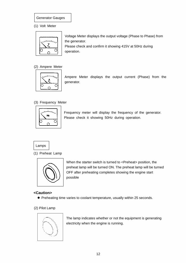
(1) Preheat Lamp
When the starter switch is turned to <Preheat> position, the
preheat lamp will be turned ON. The preheat lamp will be turned
OFF after preheating completes showing the engine start
possible
<Caution>
Preheating time varies to coolant temperature, usually within 25 seconds.
(2) Pilot Lamp
The lamp indicates whether or not the equipment is generating
electricity when the engine is running.
Generator Gauges
Lamps
13
(3) Panel Light Panel light turns ON to illuminate the panel, when turning the
switch (by the light) to ON.
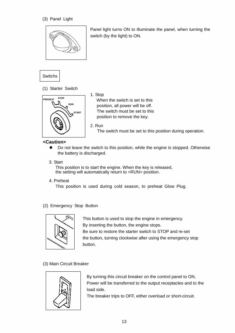
(1) Starter Switch 1. Stop
When the switch is set to this position, all power will be off. The switch must be set to this position to remove the key.
2. Run
The switch must be set to this position during operation. <Caution> Do not leave the switch to this position, while the engine is stopped. Otherwise
the battery is discharged. 3. Start
This position is to start the engine. When the key is released, the setting will automatically return to <RUN> position.
4. Preheat This position is used during cold season, to preheat Glow Plug.
(2) Emergency Stop Button
This button is used to stop the engine in emergency.
By inserting the button, the engine stops.
Be sure to restore the starter switch to STOP and re-set
the button, turning clockwise after using the emergency stop
button.
(3) Main Circuit Breaker
By turning this circuit breaker on the control panel to ON,
Power will be transferred to the output receptacles and to the
load side.
The breaker trips to OFF, either overload or short-circuit.
Switchs
STOP
RUN
START
PREHEAT
14
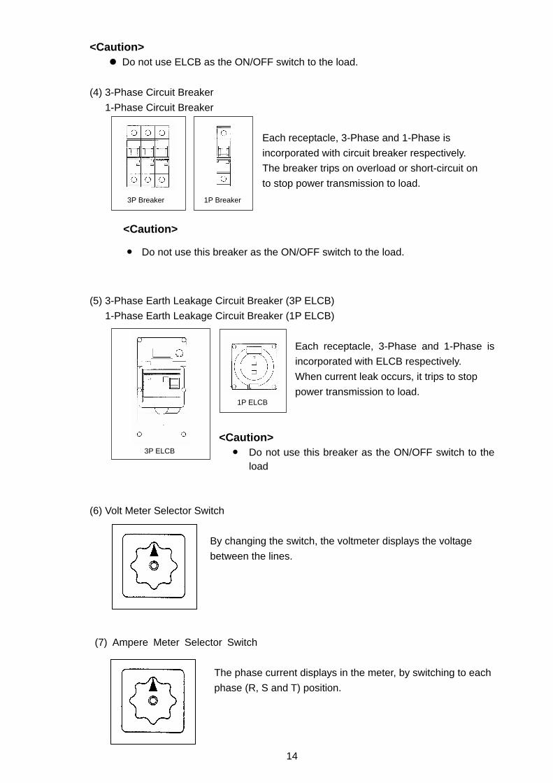
3P Breaker 1P Breaker
3P ELCB
<Caution> Do not use ELCB as the ON/OFF switch to the load.
(4) 3-Phase Circuit Breaker
1-Phase Circuit Breaker
Each receptacle, 3-Phase and 1-Phase is
incorporated with circuit breaker respectively.
The breaker trips on overload or short-circuit on
to stop power transmission to load.
<Caution>
Do not use this breaker as the ON/OFF switch to the load.
(5) 3-Phase Earth Leakage Circuit Breaker (3P ELCB)
1-Phase Earth Leakage Circuit Breaker (1P ELCB)
Each receptacle, 3-Phase and 1-Phase is
incorporated with ELCB respectively.
When current leak occurs, it trips to stop
power transmission to load.
<Caution> Do not use this breaker as the ON/OFF switch to the
load
(6) Volt Meter Selector Switch
By changing the switch, the voltmeter displays the voltage
between the lines.
(7) Ampere Meter Selector Switch
The phase current displays in the meter, by switching to each
phase (R, S and T) position.
1P ELCB
15
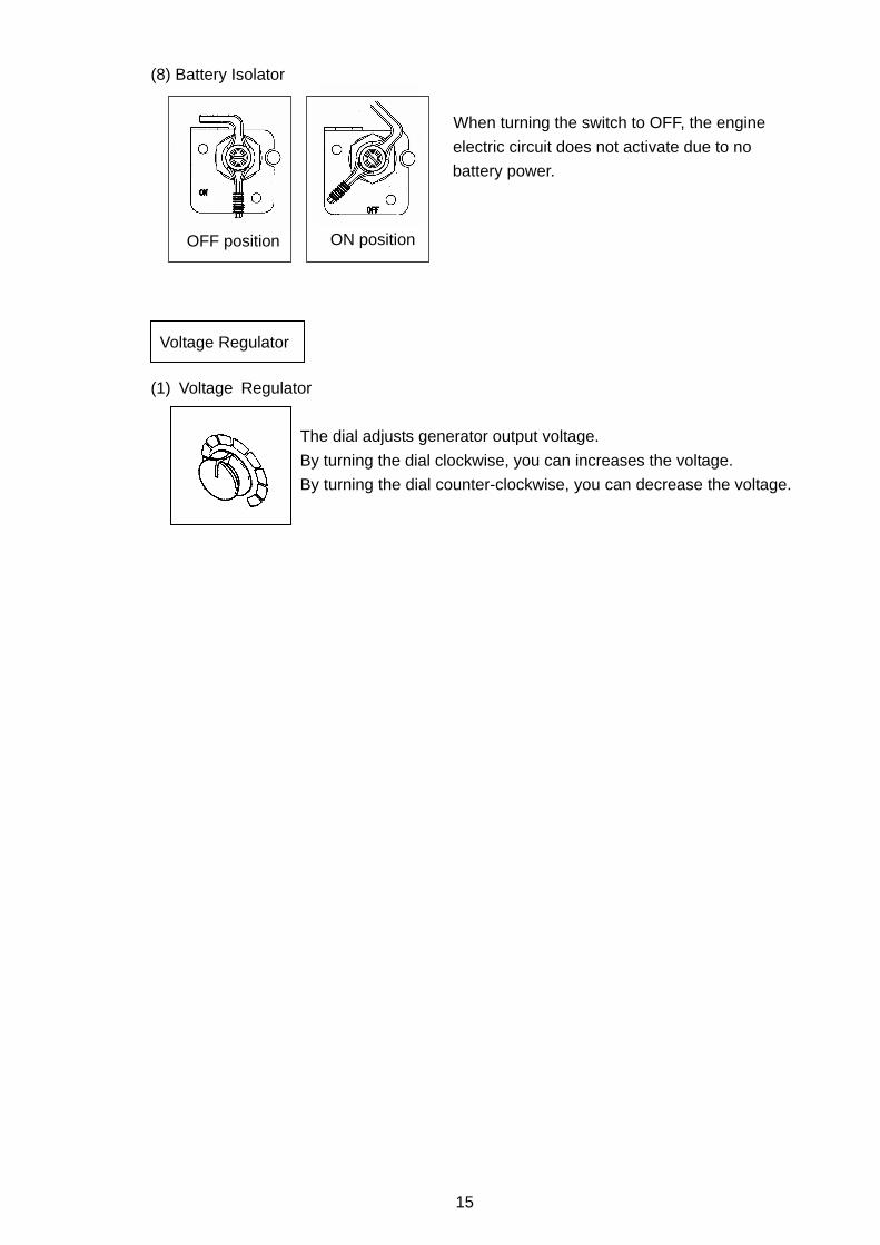
(8) Battery Isolator
When turning the switch to OFF, the engine
electric circuit does not activate due to no
battery power.
(1) Voltage Regulator
The dial adjusts generator output voltage.
By turning the dial clockwise, you can increases the voltage.
By turning the dial counter-clockwise, you can decrease the voltage.
Voltage Regulator
OFF position ON position
16
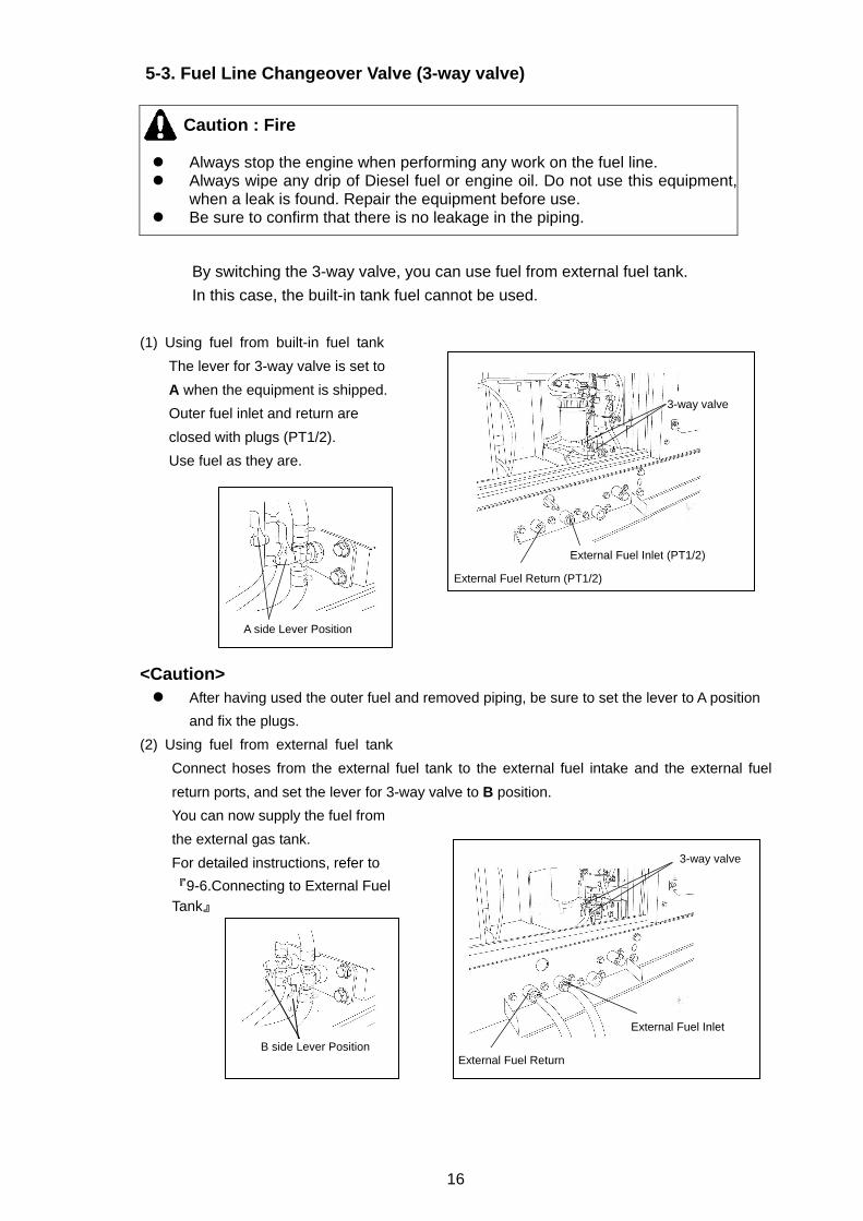
5-3. Fuel Line Changeover Valve (3-way valve)
By switching the 3-way valve, you can use fuel from external fuel tank.
In this case, the built-in tank fuel cannot be used.
(1) Using fuel from built-in fuel tank
The lever for 3-way valve is set to
A when the equipment is shipped.
Outer fuel inlet and return are
closed with plugs (PT1/2).
Use fuel as they are.
<Caution> After having used the outer fuel and removed piping, be sure to set the lever to A position
and fix the plugs.
(2) Using fuel from external fuel tank
Connect hoses from the external fuel tank to the external fuel intake and the external fuel
return ports, and set the lever for 3-way valve to B position.
You can now supply the fuel from
the external gas tank.
For detailed instructions, refer to
『9-6.Connecting to External Fuel Tank』
Caution : Fire Always stop the engine when performing any work on the fuel line. Always wipe any drip of Diesel fuel or engine oil. Do not use this equipment,
when a leak is found. Repair the equipment before use. Be sure to confirm that there is no leakage in the piping.
3-way valve
External Fuel Inlet (PT1/2)
External Fuel Return (PT1/2)
A side Lever Position
B side Lever Position
3-way valve
External Fuel Inlet
External Fuel Return
17
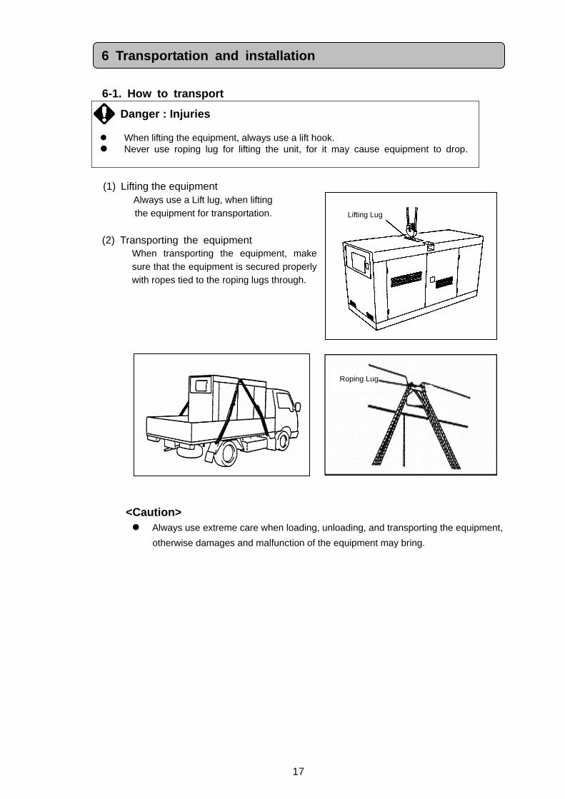
Roping Lug
6-1. How to transport
Danger : Injuries When lifting the equipment, always use a lift hook. Never use roping lug for lifting the unit, for it may cause equipment to drop.
(1) Lifting the equipment
Always use a Lift lug, when lifting the equipment for transportation.
(2) Transporting the equipment
When transporting the equipment, make sure that the equipment is secured properly with ropes tied to the roping lugs through.
<Caution> Always use extreme care when loading, unloading, and transporting the equipment,
otherwise damages and malfunction of the equipment may bring.
6 Transportation and installation
Lifting Lug
18
6-2. Installation
Danger : Suffocation from exhaust gas Exhaust fumes from the engine contains many elements harmful to humans.
Do not operate this equipment in poorly ventilated area, such as inside a room or in a tunnel
Caution : Suffocation from exhaust gas Do not point the exhaust fume toward pedestrians or buildings.
Caution : Fire
Always operate this equipment on flat surface and, at least 1 meter away
from any objects (wall, box, etc.). Temperature around muffler and exhaust can get extremely high. Keep any
inflammable items (such as fuel, gas, paint, etc.) away from the equipment.
Always set the equipment on hard, flat surface.
Keep the equipment at least 1m from a wall or any obstacles, to allow workable
space to access the control panel and opening of the panel door.
<Caution> This equipment must be operated on hard and flat surface. Operating under any
other conditions may result in malfunctions.
Do not block the airflow from radiator vent or muffler exhaust. It may result in
reduced engine performance, overheating, or damage to the electrical parts.
Operating in dusty area or salty air (by the ocean), or any other particulate
environment may result in clogged radiator, which may cause overheating, other
malfunctions and insulation deterioration. Use extreme care, frequent checks
and maintenance.
19
7-1. Select Load Cable Select the cable with proper gauge, based on its allowable amperage and the
distance between the generator and the machinery to be connected.
Caution : Damage to properties If the load exceeds the allowable amperage, the damage to the cable may
be damaged in overheating. If the cable is either too long or too small gauge, there will be greater voltage
drop between cables which brings voltage drop to loads. It may result in reduced performance in the connected loads, malfunction, or damages.
<Caution> It is recommended to select the proper gauge and length of cable, in
consideration of the maximum 5% marginal drop only for the rated voltage,
between the terminals of loads and generator via the cables.
Expedient Formula: the voltage drop of cables
3-Phase 3-Wire
1 Length (m)
Voltage Drop (V) = × × Current (A) × √3
58 Dia (mm2)
1-Phase 2-Wire
1 Length (m)
Voltage Drop (V) = × × Current (A) ×2
58 Dia (mm2)
7 Connecting Load
20
7-2. Connecting Load Cable
Danger : Electric Shock Before connecting or disconnecting a load cable from output receptacles,
always turn a circuit breaker to OFF position, stop the engine, and remove the engine key. The person performing the maintenance should always keep the key.
Caution : Fire Do not connect AC output to any indoor wiring.
<Caution> Divide loads into 3 circuits proportionally as possible, when using the maximum
output power especially, and connect them to each phase (R,S,T) respectively.
Be careful to limit the current under the rated current per the phase.
Note that the 1-phase output power decreases when 3-phase output power is
used simultaneously.
Be careful to limit the total current under the rated output current when using 1-Phase and 3-Phase output simultaneously.
21
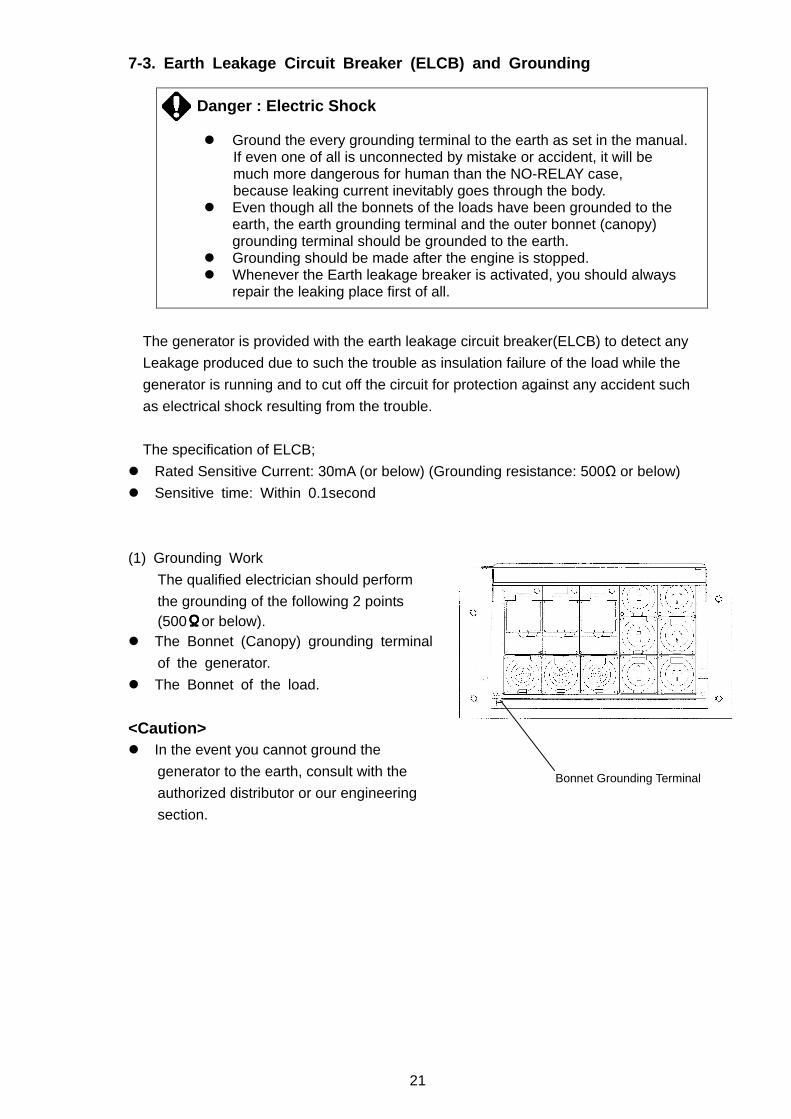
7-3. Earth Leakage Circuit Breaker (ELCB) and Groun ding
Danger : Electric Shock
Ground the every grounding terminal to the earth as set in the manual. If even one of all is unconnected by mistake or accident, it will be much more dangerous for human than the NO-RELAY case, because leaking current inevitably goes through the body. Even though all the bonnets of the loads have been grounded to the
earth, the earth grounding terminal and the outer bonnet (canopy) grounding terminal should be grounded to the earth.
Grounding should be made after the engine is stopped. Whenever the Earth leakage breaker is activated, you should always
repair the leaking place first of all.
The generator is provided with the earth leakage circuit breaker(ELCB) to detect any
Leakage produced due to such the trouble as insulation failure of the load while the
generator is running and to cut off the circuit for protection against any accident such
as electrical shock resulting from the trouble.
The specification of ELCB;
Rated Sensitive Current: 30mA (or below) (Grounding resistance: 500Ω or below)
Sensitive time: Within 0.1second
(1) Grounding Work
The qualified electrician should perform
the grounding of the following 2 points (500ΩΩΩΩor below).
The Bonnet (Canopy) grounding terminal
of the generator.
The Bonnet of the load.
<Caution> In the event you cannot ground the
generator to the earth, consult with the
authorized distributor or our engineering
section.
Bonnet Grounding Terminal
22
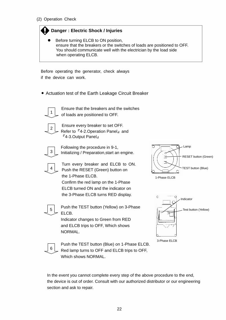
(2) Operation Check
Before operating the generator, check always
if the device can work.
Actuation test of the Earth Leakage Circuit Breaker
Ensure that the breakers and the switches
of loads are positioned to OFF. Ensure every breaker to set OFF. Refer to『4-2.Operation Panel』and 『4-3.Output Panel』 Following the procedure in 9-1, Initializing / Preparation,start an engine. Turn every breaker and ELCB to ON.
Push the RESET (Green) button on
the 1-Phase ELCB.
Confirm the red lamp on the 1-Phase
ELCB turned ON and the indicator on
the 3-Phase ELCB turns RED display.
Push the TEST button (Yellow) on 3-Phase
ELCB.
Indicator changes to Green from RED
and ELCB trips to OFF, Which shows
NORMAL.
Push the TEST button (Blue) on 1-Phase ELCB.
Red lamp turns to OFF and ELCB trips to OFF,
Which shows NORMAL.
In the event you cannot complete every step of the above procedure to the end,
the device is out of order. Consult with our authorized distributor or our engineering
section and ask to repair.
Danger : Electric Shock / Injuries Before turning ELCB to ON position,
ensure that the breakers or the switches of loads are positioned to OFF. You should communicate well with the electrician by the load side when operating ELCB.
1
3
2
4
Test button (Yellow)
Indicator
3-Phase ELCB
5
RESET button (Green)
TEST button (Blue)
Lamp
1-Phase ELCB
6
23
(3) ELCB has activated.
When the ELCB has activated, repair the leakage point and restore it by the following
procedure.
(Overload happens when the breaker activates but the Earth leakage breaker does
not activate.)
Turn the 3-Phase ELCB to ON to restore. Turn the 1-Phase ELCB to RESET to restore.
By the above procedure, you can reset the ELCB to ON positions.
1
24
Danger : Electric Shock / Injuries Before performing any equipment check or maintenance, stop the engine,
and remove the engine key. The person performing the maintenance should always keep the key.
Caution : Fire / Burns When checking engine, always stop the engine, and keep away from fire.
Wait until the engine cools down, before performing any checks.
Caution : Fire Always wipe any drip of fuel or oil. Do not use this equipment
when a leak is found. Repair the equipment before use.
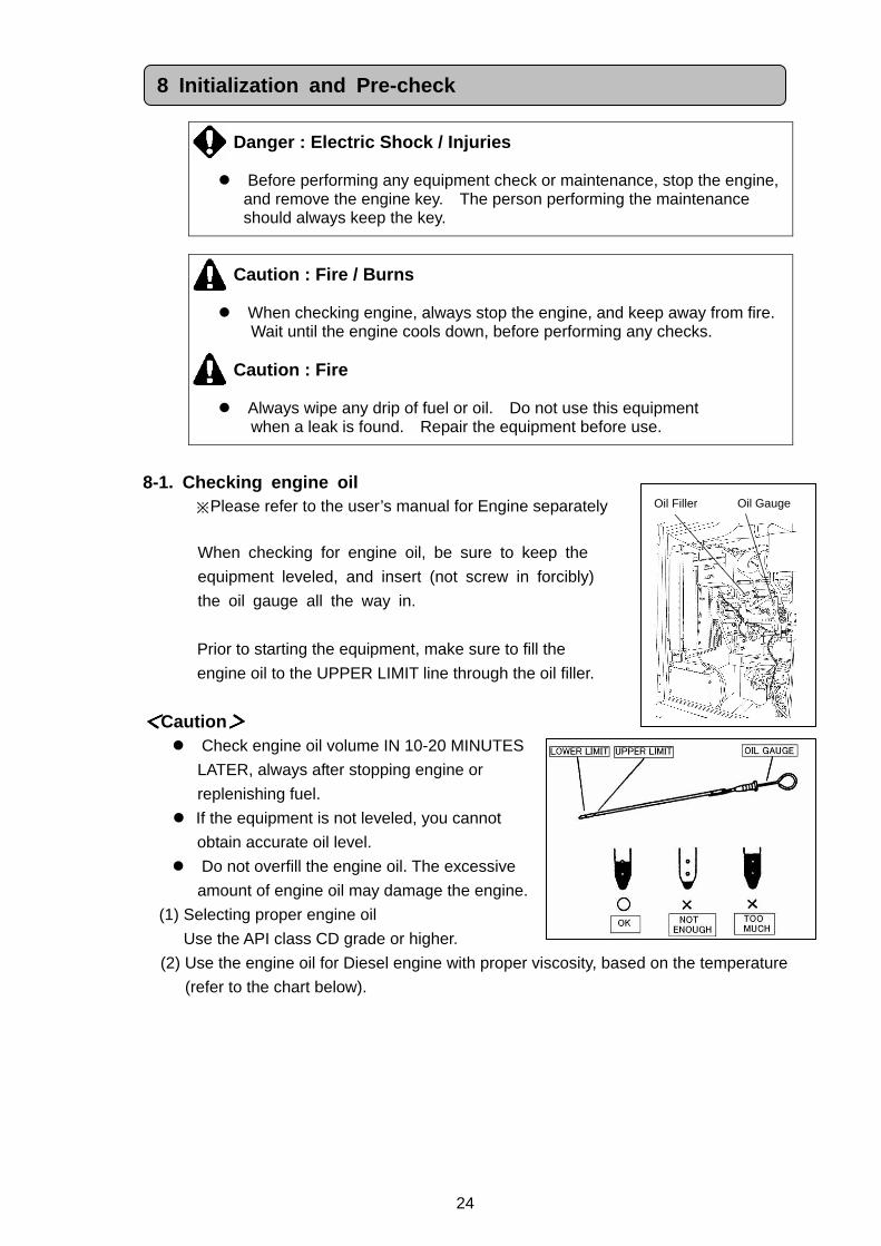
8-1. Checking engine oil ※Please refer to the user’s manual for Engine separately
When checking for engine oil, be sure to keep the
equipment leveled, and insert (not screw in forcibly)
the oil gauge all the way in.
Prior to starting the equipment, make sure to fill the
engine oil to the UPPER LIMIT line through the oil filler.
<<<<Caution>>>> Check engine oil volume IN 10-20 MINUTES
LATER, always after stopping engine or
replenishing fuel.
If the equipment is not leveled, you cannot
obtain accurate oil level.
Do not overfill the engine oil. The excessive
amount of engine oil may damage the engine.
(1) Selecting proper engine oil
Use the API class CD grade or higher.
(2) Use the engine oil for Diesel engine with proper viscosity, based on the temperature
(refer to the chart below).
8 Initialization and Pre-check
Oil Gauge Oil Filler
25
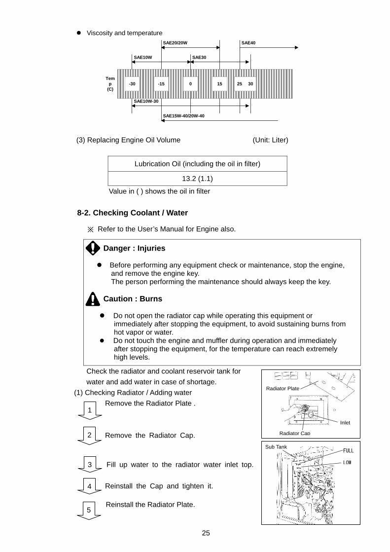
Viscosity and temperature
-30 -15 0 15 25 30
SAE10W SAE30
SAE40SAE20/20W
SAE10W-30
SAE15W-40/20W-40
Temp
(C)
(3) Replacing Engine Oil Volume (Unit: Liter)
Lubrication Oil (including the oil in filter)
13.2 (1.1)
Value in ( ) shows the oil in filter
8-2. Checking Coolant / Water
※ Refer to the User’s Manual for Engine also.
Danger : Injuries Before performing any equipment check or maintenance, stop the engine,
and remove the engine key. The person performing the maintenance should always keep the key.
Caution : Burns
Do not open the radiator cap while operating this equipment or
immediately after stopping the equipment, to avoid sustaining burns from hot vapor or water.
Do not touch the engine and muffler during operation and immediately after stopping the equipment, for the temperature can reach extremely high levels.
Check the radiator and coolant reservoir tank for
water and add water in case of shortage.
(1) Checking Radiator / Adding water
Remove the Radiator Plate .
Remove the Radiator Cap.
Fill up water to the radiator water inlet top.
Reinstall the Cap and tighten it. Reinstall the Radiator Plate.
1
2
3
4
5
Radiator Cap
Radiator Plate
Inlet
Sub Tank FULL
LOW
26
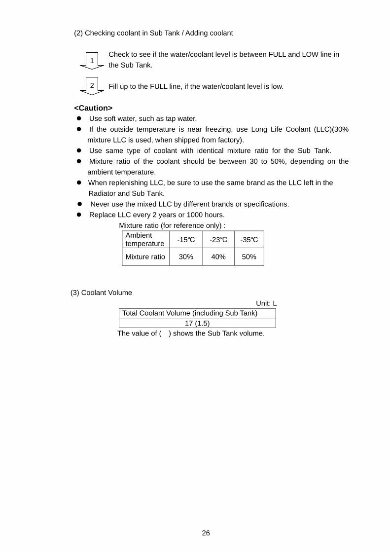
(2) Checking coolant in Sub Tank / Adding coolant
Check to see if the water/coolant level is between FULL and LOW line in
the Sub Tank.
Fill up to the FULL line, if the water/coolant level is low.
<Caution> Use soft water, such as tap water.
If the outside temperature is near freezing, use Long Life Coolant (LLC)(30%
mixture LLC is used, when shipped from factory).
Use same type of coolant with identical mixture ratio for the Sub Tank.
Mixture ratio of the coolant should be between 30 to 50%, depending on the
ambient temperature.
When replenishing LLC, be sure to use the same brand as the LLC left in the
Radiator and Sub Tank.
Never use the mixed LLC by different brands or specifications.
Replace LLC every 2 years or 1000 hours.
Mixture ratio (for reference only) : Ambient temperature -15 -23 -35
Mixture ratio 30% 40% 50%
(3) Coolant Volume
Unit: L Total Coolant Volume (including Sub Tank)
17 (1.5) The value of ( ) shows the Sub Tank volume.
1
2
27
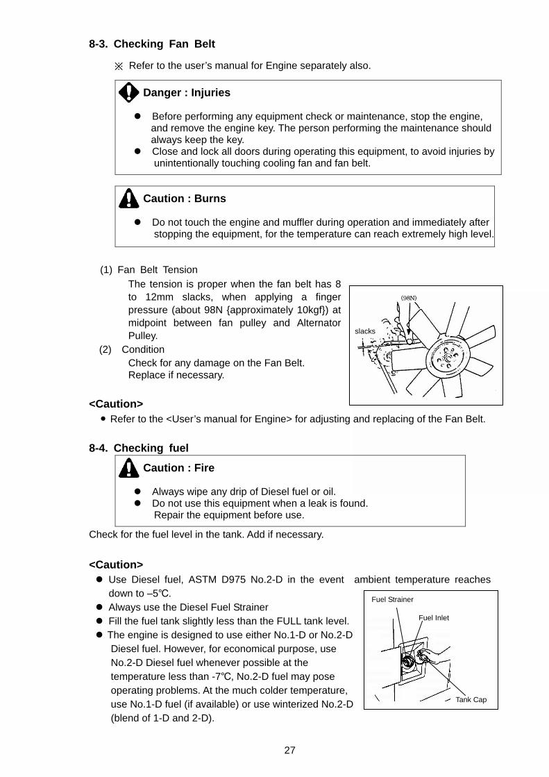
8-3. Checking Fan Belt
※ Refer to the user’s manual for Engine separately also.
Danger : Injuries Before performing any equipment check or maintenance, stop the engine,
and remove the engine key. The person performing the maintenance should always keep the key.
Close and lock all doors during operating this equipment, to avoid injuries by unintentionally touching cooling fan and fan belt.
Caution : Burns Do not touch the engine and muffler during operation and immediately after
stopping the equipment, for the temperature can reach extremely high level.
(1) Fan Belt Tension The tension is proper when the fan belt has 8 to 12mm slacks, when applying a finger pressure (about 98N approximately 10kgf) at midpoint between fan pulley and Alternator Pulley.
(2) Condition Check for any damage on the Fan Belt. Replace if necessary.
<Caution>
Refer to the <User’s manual for Engine> for adjusting and replacing of the Fan Belt.
8-4. Checking fuel
Caution : Fire Always wipe any drip of Diesel fuel or oil. Do not use this equipment when a leak is found.
Repair the equipment before use.
Check for the fuel level in the tank. Add if necessary.
<Caution> Use Diesel fuel, ASTM D975 No.2-D in the event ambient temperature reaches
down to –5. Always use the Diesel Fuel Strainer Fill the fuel tank slightly less than the FULL tank level. The engine is designed to use either No.1-D or No.2-D
Diesel fuel. However, for economical purpose, use No.2-D Diesel fuel whenever possible at the temperature less than -7, No.2-D fuel may pose operating problems. At the much colder temperature, use No.1-D fuel (if available) or use winterized No.2-D (blend of 1-D and 2-D).
slacks
Tank Cap
Fuel Strainer
Fuel Inlet
28
This blended fuel is usually called also No.2-D. It can be used in colder temperature than N0.2-D fuel, which has not been winterized. Check with service station operator to be sure you can get the proper blend fuel.
Fuel requirements:
NOTICE: The fuel injection pump, injector or other parts of the fuel system and engine can be damaged if you use any fuel or fuel additive other than those specifically recommended by Isuzu. Such damage is not our responsibility, and is not covered by the Warranty. To help avoid fuel system or engine damage, please heed the following: Some service stations mix used engine oil with diesel fuel. Some
manufacturers of large diesel engines allow this; however, for your diesel engine, do not use the diesel fuel which has been contaminated with engine oil. Besides causing engine damage, such fuel can also affect emission control. Before using any diesel fuel, check with the service station operator to see if the fuel has been mixed with engine oil. Do not use any fuel additive. At the time this manual was printed, no other
fuel additive was recommended. (See your authorized dealer to find out if this has changed.)
8-5. Checking Fuel, Engine Oil, and Coolant leakage
Caution : Fire Never use this equipment when a leak is found. Repair the equipment first
of all.
Be sure to check for any fuel leak at the fuel hose connections, and oil and coolant
leak by opening Side Doors.
8-6. Checking Battery
Caution : Injuries to eyes and skin Battery fluid contains diluted sulfuric acid. Avoid contact with eyes, skin
or on clothing. If the acid comes in contact, especially with eyes, flush with a lot of water, and contact physician or doctor immediately.
Caution: Explosion
When the liquid level is below the LOWER level, never use the equipment
nor recharge battery. Battery may emit some combustible gas, so keep it away from fire and
sparks.
Check the fluid level. If the level is near or lower than the LOWER LEVEL,
add distilled water until the fluid level reaches the UPPER LEVEL limit.
Make sure that the battery cables are firmly secured to the posts. Tighten
the clamps more if necessary.
<Caution> Check the hydrometer of the battery fluid. If it falls below 1.23, the
battery requires recharging. Please call our authorized distributor or our
engineering section.
1
2
29
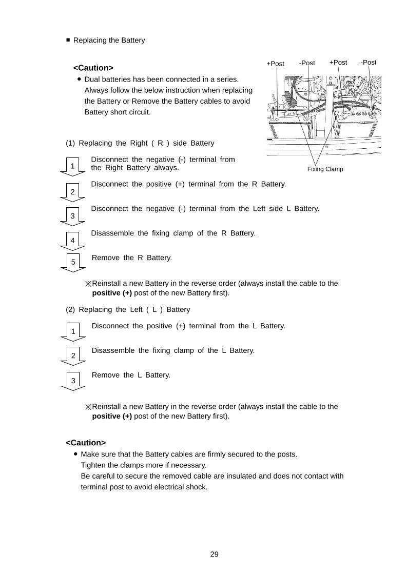
Replacing the Battery
<Caution>
Dual batteries has been connected in a series.
Always follow the below instruction when replacing
the Battery or Remove the Battery cables to avoid
Battery short circuit.
(1) Replacing the Right ( R ) side Battery
Disconnect the negative (-) terminal from the Right Battery always.
Disconnect the positive (+) terminal from the R Battery. Disconnect the negative (-) terminal from the Left side L Battery. Disassemble the fixing clamp of the R Battery. Remove the R Battery.
※Reinstall a new Battery in the reverse order (always install the cable to the positive (+) post of the new Battery first).
(2) Replacing the Left ( L ) Battery
Disconnect the positive (+) terminal from the L Battery.
Disassemble the fixing clamp of the L Battery. Remove the L Battery.
※Reinstall a new Battery in the reverse order (always install the cable to the
positive (+) post of the new Battery first). <Caution>
Make sure that the Battery cables are firmly secured to the posts.
Tighten the clamps more if necessary.
Be careful to secure the removed cable are insulated and does not contact with
terminal post to avoid electrical shock.
1
2
3
4
-Post +Post
Fixing Clamp
-Post +Post
5
1
2
3
30
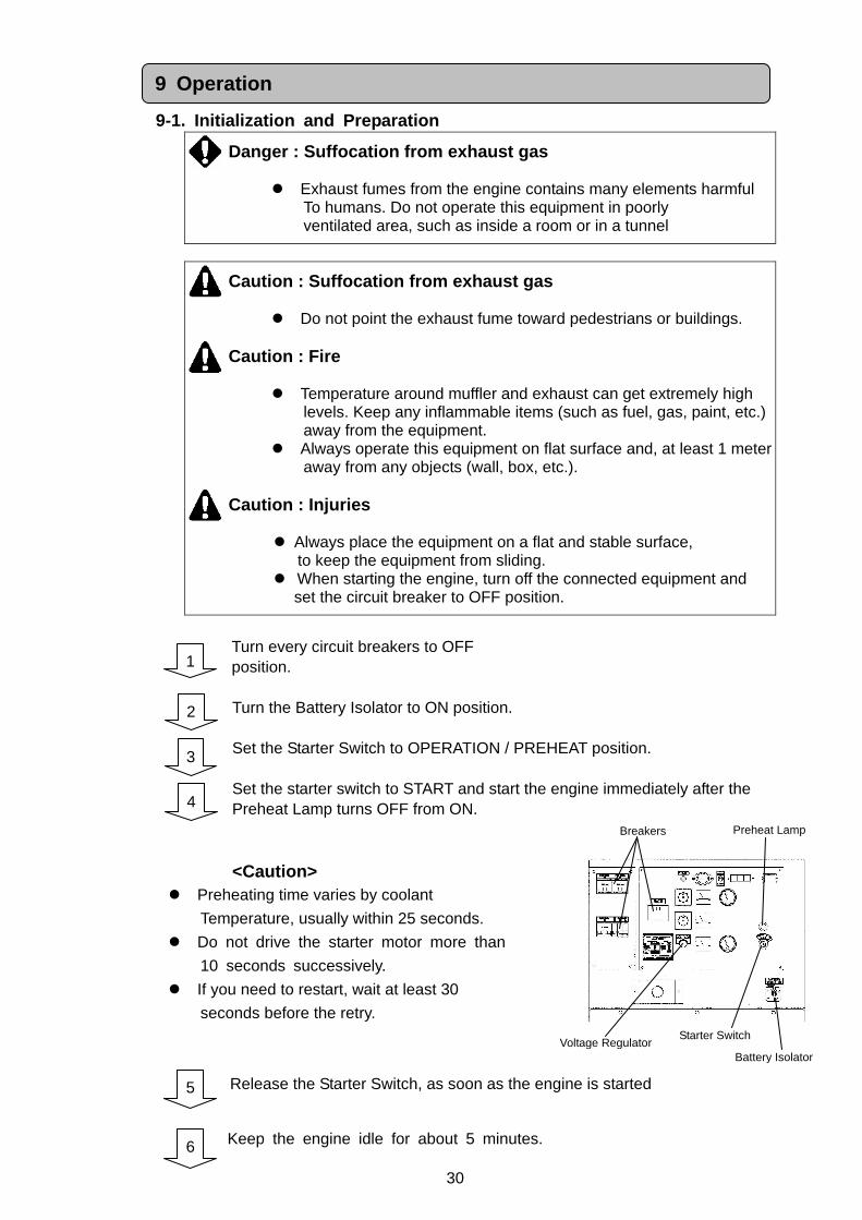
9-1. Initialization and Preparation
Danger : Suffocation from exhaust gas
Exhaust fumes from the engine contains many elements harmful To humans. Do not operate this equipment in poorly ventilated area, such as inside a room or in a tunnel
Caution : Suffocation from exhaust gas
Do not point the exhaust fume toward pedestrians or buildings.
Caution : Fire
Temperature around muffler and exhaust can get extremely high levels. Keep any inflammable items (such as fuel, gas, paint, etc.) away from the equipment.
Always operate this equipment on flat surface and, at least 1 meter away from any objects (wall, box, etc.).
Caution : Injuries
Always place the equipment on a flat and stable surface,
to keep the equipment from sliding. When starting the engine, turn off the connected equipment and
set the circuit breaker to OFF position.
Turn every circuit breakers to OFF position. Turn the Battery Isolator to ON position. Set the Starter Switch to OPERATION / PREHEAT position. Set the starter switch to START and start the engine immediately after the Preheat Lamp turns OFF from ON. <Caution>
Preheating time varies by coolant
Temperature, usually within 25 seconds.
Do not drive the starter motor more than
10 seconds successively.
If you need to restart, wait at least 30
seconds before the retry.
Release the Starter Switch, as soon as the engine is started
Keep the engine idle for about 5 minutes. 6
5
9 Operation
Preheat Lamp
Voltage Regulator Starter Switch
Breakers
1
2
3
4
Battery Isolator
31
Ensure that the tachometer shows the following frequency at no load.
No Load Frequency (Revolving Speed)
50Hz RUN
52.5Hz (about) (1575min-1)
<Caution> By setting frequency to the above frequency under no load, 50Hz(almost)
will be obtained at the rated output load.
Adjusting the Voltage Regulate Dial, set it to the required voltage.
50Hz RUN
415V
Turn the circuit breakers to ON to send power to the load side.
Danger : Electric Shock / Injuries Before turning ELCB to ON to send power to the load side,
always ensure that any circuit breaker and switch of loads are positioned to OFF. In the case the generator and the load are away from each other, proceed with the above steps, communicating well with the other person by the load in order to prevent from accident.
7
8
9
32
9-2. During Operation (1) Post startup check
Make sure that all meters (gauges) and displays are working properly.
(Refer to 5. Equipment)
Check for any unusual vibration or noise.
Check for any unusual color from the exhaust. Under normal condition,
the exhaust gas has no color or light bluish color.
<Caution> If finding out abnormality, consult with our authorized distributor or our
engineering section in order to repair, without using the machine.
(2) Adjustment during operation
Make subtle adjustment to voltage using the Voltage Regulate Dial, by monitoring
Voltage Meter during operation. Extracting the air out of the fuelling system for engine stop due to no fuel ※※※※Refer to the User’s manual for Engine. This generator is equipped with automatic extracting feature.
Thus if the engine stops due to running out of fuel, follow the next steps to extract
the air out.
Add fuel to the fuel tank.
Turn the Starter Switch to RUN position. It will take approximately 30
seconds to extract the air out.
<Caution> In the case air is in the fuel line, the engine speeds is unstable.
In the case, perform the vacuum again.
1
2
33
9-3. Stopping
Turn the switch on the equipment and the circuit breaker on the load to
OFF.
Turn every circuit breaker to OFF position.
Keep the engine NORMAL SPEED on NO LOAD for about 3 minutes.
Turn the Starter Switch to STOP.
Turn the Battery Isolator to OFF.
9-4. Protection Feature This equipment is equipped with automatic shutdown feature and display of the
location of trouble, against trouble during operation. In the event of the automatic
shutdown or alarm lamp flashing, turn off the engine and investigate the trouble
shown by alarm lamp.
Protection Feature List
※ 〇 indicates the automatic activation.
No.
Action
Abnormality
ELCB Trip
Breaker
Trip
Engine Automatic Shutdown
Warning Lamp Flash
Cause
1
High Water Temperature
ー ー 〇 〇
Activates due to high water temperature in engine
Default 105
2
Low Oil Pressure
ー ー 〇 〇
Activate due to low oil pressure in the engine Default 0.98×100kPa
1.0kgf/cm2
3
Mon
itor
Lam
p
Battery Charge Insufficient
ー ー ー 〇
Activates in battery charge Impossible
4
Current Leakage
〇 ー ー ー
Activates in current leakage
5
Overload
ー 〇 ー ー
Activates in overload
4
5
1
2
3
34
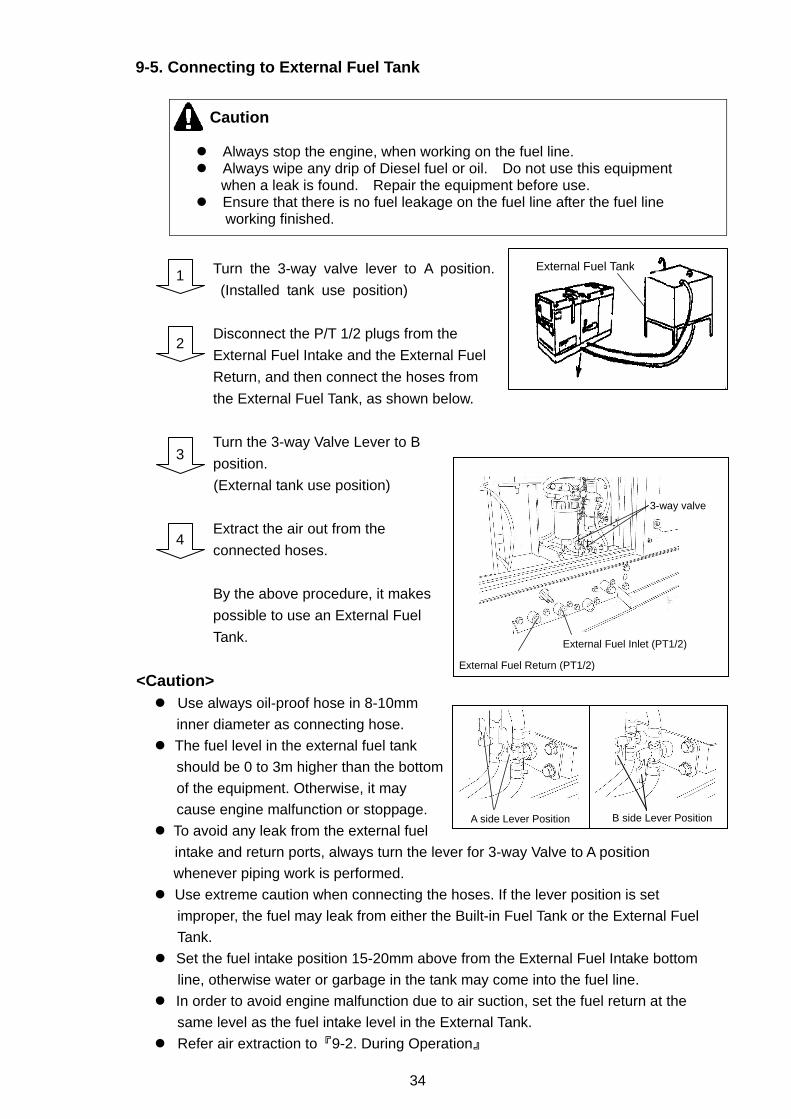
9-5. Connecting to External Fuel Tank
Caution Always stop the engine, when working on the fuel line. Always wipe any drip of Diesel fuel or oil. Do not use this equipment
when a leak is found. Repair the equipment before use. Ensure that there is no fuel leakage on the fuel line after the fuel line
working finished.
Turn the 3-way valve lever to A position.
(Installed tank use position)
Disconnect the P/T 1/2 plugs from the
External Fuel Intake and the External Fuel
Return, and then connect the hoses from
the External Fuel Tank, as shown below.
Turn the 3-way Valve Lever to B
position.
(External tank use position)
Extract the air out from the
connected hoses.
By the above procedure, it makes
possible to use an External Fuel
Tank.
<Caution> Use always oil-proof hose in 8-10mm
inner diameter as connecting hose.
The fuel level in the external fuel tank
should be 0 to 3m higher than the bottom
of the equipment. Otherwise, it may
cause engine malfunction or stoppage.
To avoid any leak from the external fuel
intake and return ports, always turn the lever for 3-way Valve to A position
whenever piping work is performed.
Use extreme caution when connecting the hoses. If the lever position is set
improper, the fuel may leak from either the Built-in Fuel Tank or the External Fuel
Tank.
Set the fuel intake position 15-20mm above from the External Fuel Intake bottom
line, otherwise water or garbage in the tank may come into the fuel line.
In order to avoid engine malfunction due to air suction, set the fuel return at the
same level as the fuel intake level in the External Tank.
Refer air extraction to『9-2. During Operation』
1
2
3
4
External Fuel Tank
A side Lever Position B side Lever Position
3-way valve
External Fuel Inlet (PT1/2)
External Fuel Return (PT1/2)
35
Just after having connected to External Fuel Tank, there may be a case that
engine speed is unstable and engine stops due to insufficient air extraction.
Therefore, be sure to confirm that the air is extracted completely and the engine
speeds keeps stable before leaving the equipment under people-less operation.
Danger : Electric Shock/Injuries Before performing any equipment check or maintenance, stop the engine,
and remove the engine key. The person performing the maintenance should always keep the key.
Caution : Fire/Burns When checking engine, always stop the engine, and keep away from fire.
Wait until the engine cools down, before performing any checks.
Caution : Fire Always wipe any drip of fuel or oil. Do not use this equipment when a
Leak is found. Repair the equipment before use.
To optimize the use of this generator, we recommend the periodical equipment checks
and maintenance, based on following maintenance matrix. Use the hour meter as a
guide for the operating time.
<Caution> The authorized technicians only should perform all maintenance work, except for
the pre-startup checks. Request for the maintenance items with mark to our authorized dealer or our
engineering section. This chart only covers the simple checks and maintenance as for the engine.
For more detailed guide, please refer to the User’s Manual for the engine. Always use our genuine parts only for replacement.
10 Check / Maintenance
36
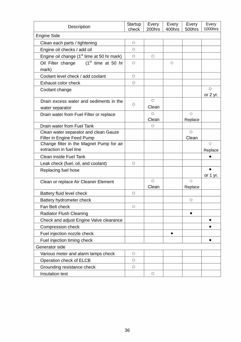
Description Startup check
Every 200hrs
Every 400hrs
Every 500hrs
Every 1000hrs
Engine Side
Clean each parts / tightening
Engine oil checks / add oil
Engine oil change (1st time at 50 hr mark)
Oil Filter change (1st time at 50 hr
mark)
Coolant level check / add coolant
Exhaust color check
Coolant change or 2 yr.
Drain excess water and sediments in the
water separator
Clean
Drain water from Fuel Filter or replace Clean
Replace
Drain water from Fuel Tank Clean water separator and clean Gauze Filter in Engine Feed Pump
Clean
Change filter in the Magnet Pump for air extraction in fuel line
Replace
Clean inside Fuel Tank
Leak check (fuel, oil, and coolant)
Replacing fuel hose or 1 yr.
Clean or replace Air Cleaner Element Clean
Replace
Battery fluid level check
Battery hydrometer check
Fan Belt check
Radiator Flush Cleaning
Check and adjust Engine Valve clearance
Compression check
Fuel injection nozzle check
Fuel injection timing check
Generator side
Various meter and alarm lamps check
Operation check of ELCB
Grounding resistance check
Insulation test
37
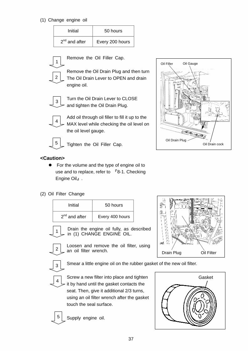
(1) Change engine oil
Remove the Oil Filler Cap.
Remove the Oil Drain Plug and then turn
The Oil Drain Lever to OPEN and drain
engine oil.
Turn the Oil Drain Lever to CLOSE
and tighten the Oil Drain Plug.
Add oil through oil filler to fill it up to the
MAX level while checking the oil level on
the oil level gauge.
Tighten the Oil Filler Cap.
<Caution> For the volume and the type of engine oil to
use and to replace, refer to 『8-1. Checking
Engine Oil』.
(2) Oil Filter Change
Drain the engine oil fully, as described in (1) CHANGE ENGINE OIL. Loosen and remove the oil filter, using an oil filter wrench.
Smear a little engine oil on the rubber gasket of the new oil filter.
Screw a new filter into place and tighten
it by hand until the gasket contacts the
seat. Then, give it additional 2/3 turns,
using an oil filter wrench after the gasket
touch the seal surface.
Supply engine oil.
Initial
50 hours
2nd and after
Every 200 hours
1
2
3
4
5
Initial
50 hours
2nd and after
Every 400 hours
1
2
3
5
4
Gasket
Oil Drain Plug
Oil Gauge Oil Filler
Oil Drain cock
Drain Plug Oil Filter
38
<Caution> If an oil filter wrench is not at hand, contact our authorized distributor or our
engineering section to replace.
Oil Filter Part No. Isuzu Part No. 8943212190
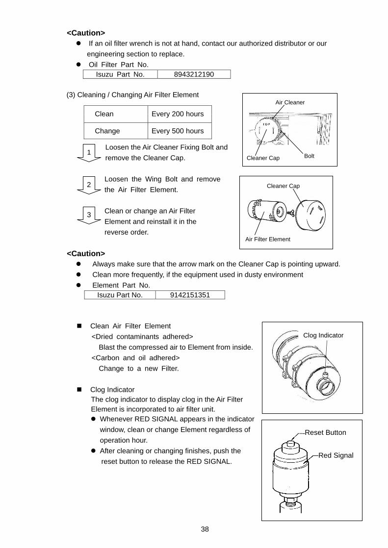
(3) Cleaning / Changing Air Filter Element
Loosen the Air Cleaner Fixing Bolt and
remove the Cleaner Cap.
Loosen the Wing Bolt and remove
the Air Filter Element.
Clean or change an Air Filter
Element and reinstall it in the
reverse order.
<Caution> Always make sure that the arrow mark on the Cleaner Cap is pointing upward.
Clean more frequently, if the equipment used in dusty environment
Element Part No. Isuzu Part No. 9142151351
Clean Air Filter Element
<Dried contaminants adhered>
Blast the compressed air to Element from inside.
<Carbon and oil adhered>
Change to a new Filter.
Clog Indicator The clog indicator to display clog in the Air Filter Element is incorporated to air filter unit. Whenever RED SIGNAL appears in the indicator
window, clean or change Element regardless of
operation hour.
After cleaning or changing finishes, push the
reset button to release the RED SIGNAL.
Clean
Every 200 hours
Change
Every 500 hours
2
3
Clog Indicator
Reset Button
Red Signal
Bolt
Air Cleaner
Cleaner Cap
Cleaner Cap
Air Filter Element
1
39
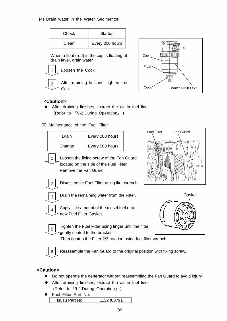
(4) Drain water in the Water Sedimentor
When a float (red) in the cup is floating at drain level, drain water.
Loosen the Cock.
After draining finishes, tighten the
Cock.
<Caution>
After draining finishes, extract the air in fuel line.
(Refer to 『9-2.During Operation』.)
(5) Maintenance of the Fuel Filter
Loosen the fixing screw of the Fan Guard
located on the side of the Fuel Filter.
Remove the Fan Guard.
Disassemble Fuel Filter using ilter wrench.
Drain the remaining water from the Filter.
Apply little amount of the diesel fuel onto
new Fuel Filter Gasket.
Tighten the Fuel Filter using finger until the filter
gently seated to the bracket,
Then tighten the Filter 2/3 rotation using fuel filter wrench.
Reassemble the Fan Guard to the original position with fixing screw.
<Caution>
Do not operate the generator without reassembling the Fan Guard to avoid injury.
After draining finishes, extract the air in fuel line.
(Refer to『9-2.During Operation』.) Fuel Filter Part No.
Isuzu Part No. 1132400791
Check Startup
Clean Every 200 hours
Drain Every 200 hours
Change Every 500 hours
1
2
2
1
Gasket
Cock
Cup
Float
Water Drain Level
Fuel Filter Fan Guard
3
4
5
6
40
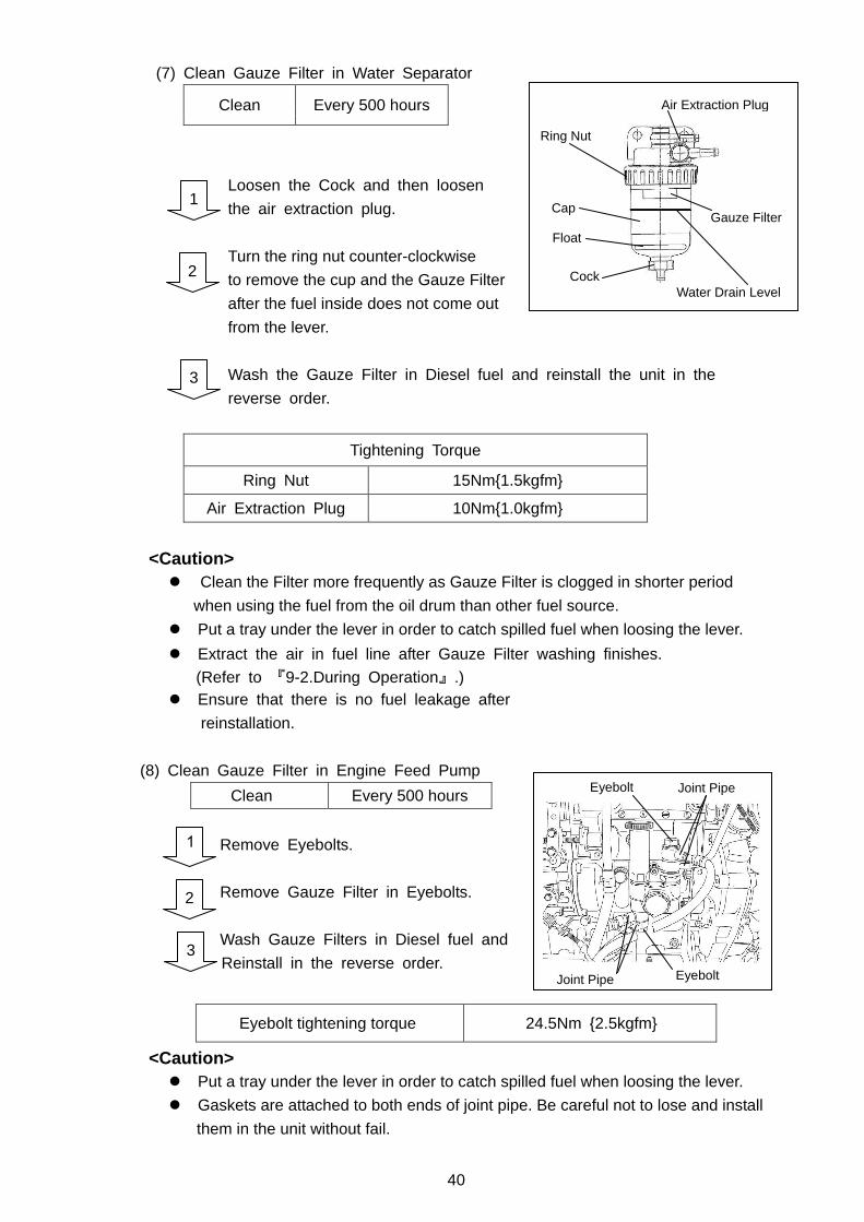
(7) Clean Gauze Filter in Water Separator
Clean Every 500 hours
Loosen the Cock and then loosen
the air extraction plug.
Turn the ring nut counter-clockwise
to remove the cup and the Gauze Filter
after the fuel inside does not come out
from the lever.
Wash the Gauze Filter in Diesel fuel and reinstall the unit in the
reverse order.
Tightening Torque
Ring Nut 15Nm1.5kgfm
Air Extraction Plug 10Nm1.0kgfm
<Caution>
Clean the Filter more frequently as Gauze Filter is clogged in shorter period
when using the fuel from the oil drum than other fuel source.
Put a tray under the lever in order to catch spilled fuel when loosing the lever.
Extract the air in fuel line after Gauze Filter washing finishes.
(Refer to 『9-2.During Operation』.) Ensure that there is no fuel leakage after
reinstallation.
(8) Clean Gauze Filter in Engine Feed Pump
Clean Every 500 hours
Remove Eyebolts.
Remove Gauze Filter in Eyebolts.
Wash Gauze Filters in Diesel fuel and
Reinstall in the reverse order.
<Caution>
Put a tray under the lever in order to catch spilled fuel when loosing the lever.
Gaskets are attached to both ends of joint pipe. Be careful not to lose and install
them in the unit without fail.
Eyebolt tightening torque 24.5Nm 2.5kgfm
1
2
3
1
2
3
Ring Nut
Cap
Air Extraction Plug
Gauze Filter
Water Drain Level Cock
Float
Eyebolt Joint Pipe
Joint Pipe Eyebolt
41
Change both Gauze Filter and eyebolt
when Gauze Filter is damaged.
Extract the air in fuel line after Gauze Filter washing
finishes.
(Refer to 『9-2.During Operation』.) Ensure that there is no fuel leakage after
reinstallation.
Eyebolt Part No. (Gauze Filter included)
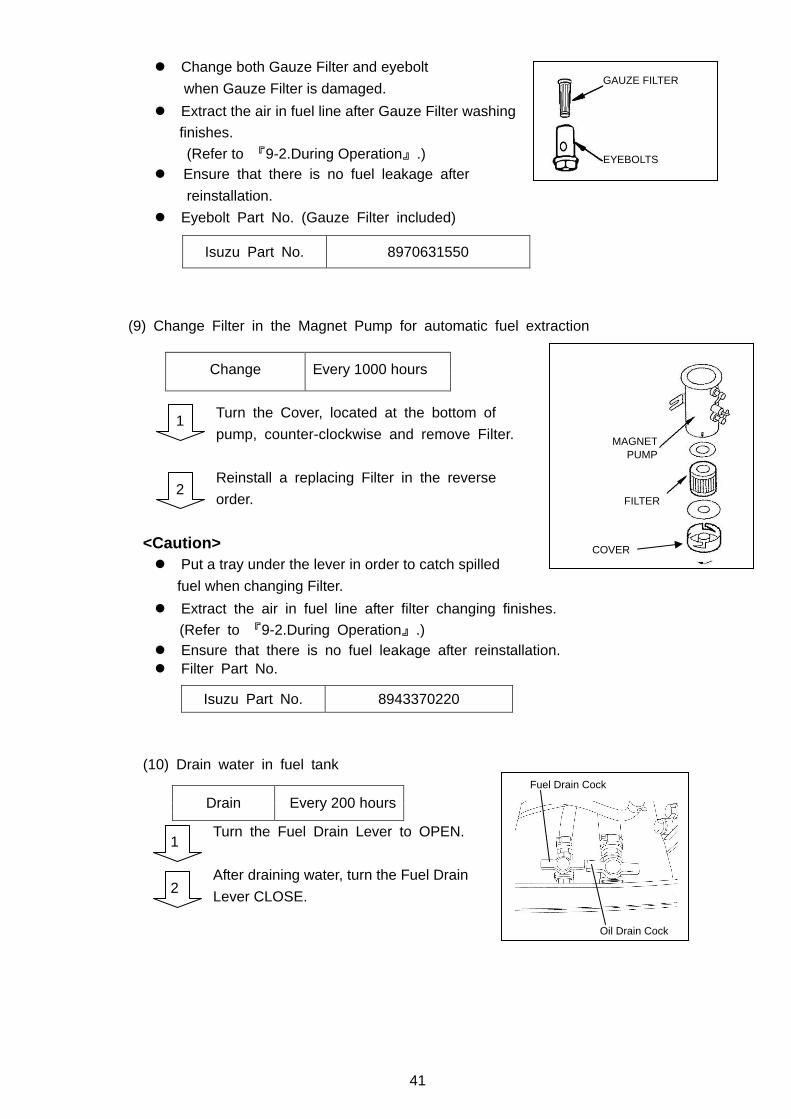
(9) Change Filter in the Magnet Pump for automatic fuel extraction
Turn the Cover, located at the bottom of
pump, counter-clockwise and remove Filter.
Reinstall a replacing Filter in the reverse
order.
<Caution>
Put a tray under the lever in order to catch spilled
fuel when changing Filter.
Extract the air in fuel line after filter changing finishes.
(Refer to 『9-2.During Operation』.) Ensure that there is no fuel leakage after reinstallation. Filter Part No.
(10) Drain water in fuel tank
Turn the Fuel Drain Lever to OPEN.
After draining water, turn the Fuel Drain
Lever CLOSE.
Isuzu Part No. 8970631550
Isuzu Part No. 8943370220
Drain Every 200 hours
1
2
Change
Every 1000 hours
1
2
GAUZE FILTER
EYEBOLTS
COVER
MAGNET PUMP
FILTER
Oil Drain Cock
Fuel Drain Cock
42
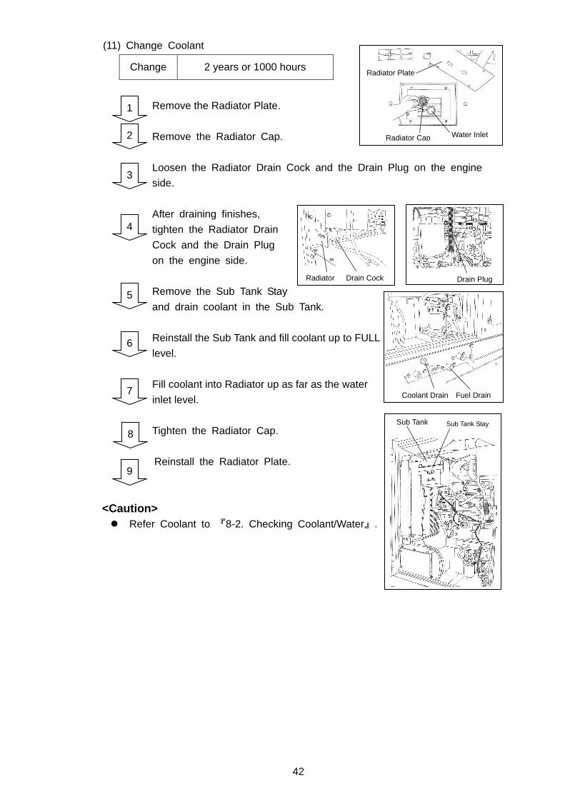
(11) Change Coolant
Remove the Radiator Plate.
Remove the Radiator Cap.
Loosen the Radiator Drain Cock and the Drain Plug on the engine
side.
After draining finishes,
tighten the Radiator Drain
Cock and the Drain Plug
on the engine side.
Remove the Sub Tank Stay
and drain coolant in the Sub Tank.
Reinstall the Sub Tank and fill coolant up to FULL
level.
Fill coolant into Radiator up as far as the water
inlet level.
Tighten the Radiator Cap.
Reinstall the Radiator Plate.
<Caution> Refer Coolant to 『8-2. Checking Coolant/Water』.
2
3
4
5
6
7
9
1
Change
2 years or 1000 hours
8
Radiator Cap
Radiator Plate
Water Inlet
Radiator Drain Cock Drain Plug
Coolant Drain Fuel Drain
Sub Tank Sub Tank Stay
43
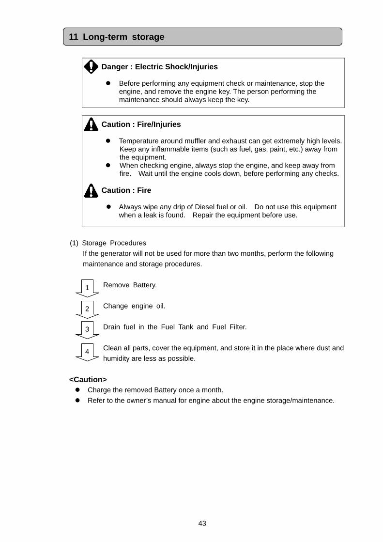
Danger : Electric Shock/Injuries
Before performing any equipment check or maintenance, stop the engine, and remove the engine key. The person performing the maintenance should always keep the key.
Caution : Fire/Injuries
Temperature around muffler and exhaust can get extremely high levels. Keep any inflammable items (such as fuel, gas, paint, etc.) away from the equipment.
When checking engine, always stop the engine, and keep away from fire. Wait until the engine cools down, before performing any checks.
Caution : Fire
Always wipe any drip of Diesel fuel or oil. Do not use this equipment
when a leak is found. Repair the equipment before use.
(1) Storage Procedures
If the generator will not be used for more than two months, perform the following
maintenance and storage procedures.
Remove Battery.
Change engine oil.
Drain fuel in the Fuel Tank and Fuel Filter.
Clean all parts, cover the equipment, and store it in the place where dust and
humidity are less as possible.
<Caution> Charge the removed Battery once a month.
Refer to the owner’s manual for engine about the engine storage/maintenance.
1
2
3
4
11 Long-term storage
44
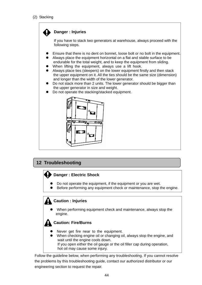
(2) Stacking
Danger : Electric Shock Do not operate the equipment, if the equipment or you are wet. Before performing any equipment check or maintenance, stop the engine.
Caution : Injuries When performing equipment check and maintenance, always stop the
engine.
Caution: Fire/Burns Never get fire near to the equipment. When checking engine oil or changing oil, always stop the engine, and
wait until the engine cools down. If you open either the oil gauge or the oil filler cap during operation, hot oil may cause some injury.
Follow the guideline below, when performing any troubleshooting. If you cannot resolve
the problems by this troubleshooting guide, contact our authorized distributor or our
engineering section to request the repair.
Danger : Injuries If you have to stack two generators at warehouse, always proceed with the following steps.
Ensure that there is no dent on bonnet, loose bolt or no bolt in the equipment. Always place the equipment horizontal on a flat and stable surface to be
endurable for the total weight, and to keep the equipment from sliding. When lifting the equipment, always use a lift hook. Always place ties (sleepers) on the lower equipment firstly and then stack
the upper equipment on it. All the ties should be the same size (dimension) and longer than the width of the lower generator.
Do not stack more than 2 units. The lower generator should be bigger than the upper generator in size and weight.
Do not operate the stacking/stacked equipment.
12 Troubleshooting
45
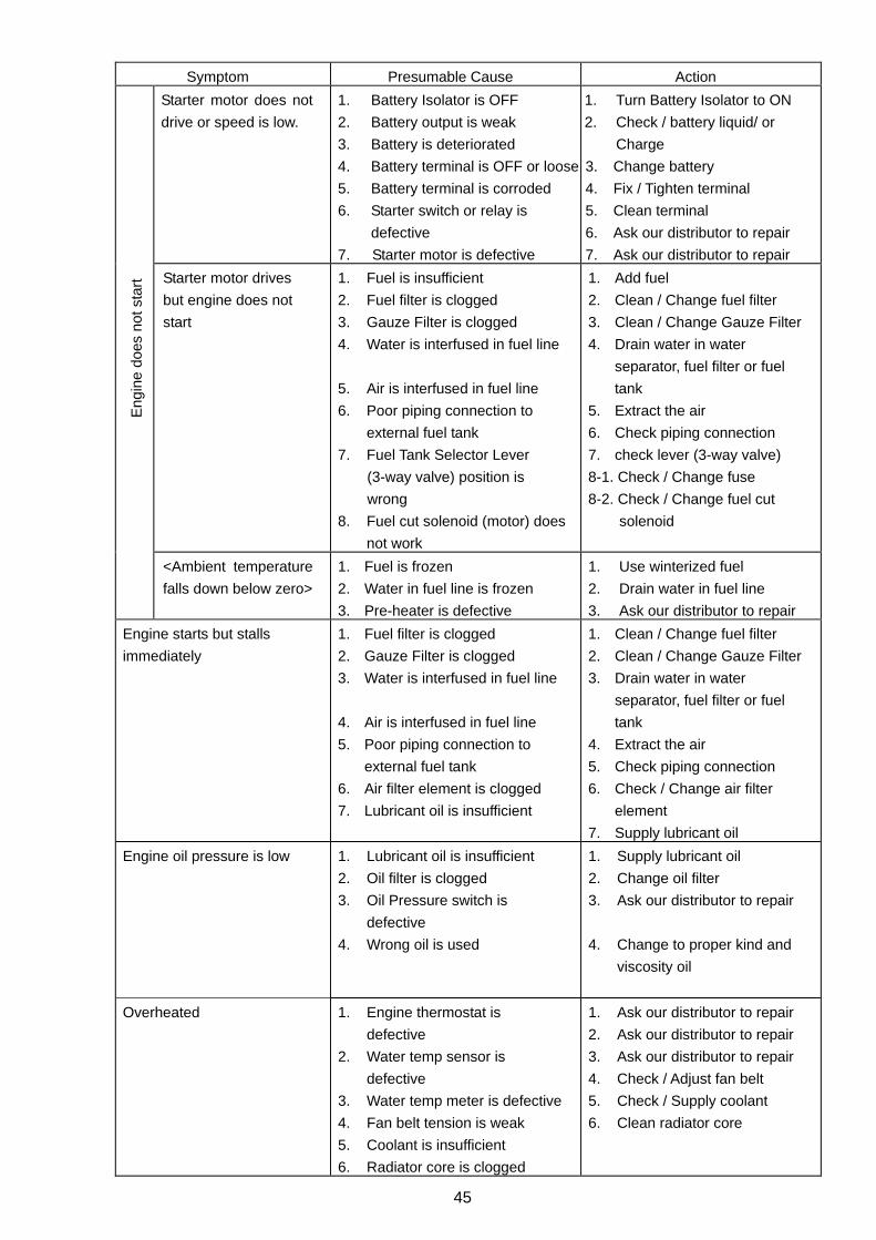
Symptom Presumable Cause Action
Starter motor does not
drive or speed is low.
1. Battery Isolator is OFF
2. Battery output is weak
3. Battery is deteriorated
4. Battery terminal is OFF or loose
5. Battery terminal is corroded
6. Starter switch or relay is
defective
7. Starter motor is defective
1. Turn Battery Isolator to ON
2. Check / battery liquid/ or
Charge
3. Change battery
4. Fix / Tighten terminal
5. Clean terminal
6. Ask our distributor to repair
7. Ask our distributor to repair
Starter motor drives
but engine does not
start
1. Fuel is insufficient
2. Fuel filter is clogged
3. Gauze Filter is clogged
4. Water is interfused in fuel line
5. Air is interfused in fuel line
6. Poor piping connection to
external fuel tank
7. Fuel Tank Selector Lever
(3-way valve) position is
wrong
8. Fuel cut solenoid (motor) does
not work
1. Add fuel
2. Clean / Change fuel filter
3. Clean / Change Gauze Filter
4. Drain water in water
separator, fuel filter or fuel
tank
5. Extract the air
6. Check piping connection
7. check lever (3-way valve)
8-1. Check / Change fuse
8-2. Check / Change fuel cut
solenoid
Eng
ine
does
not
sta
rt
<Ambient temperature
falls down below zero>
1. Fuel is frozen
2. Water in fuel line is frozen
3. Pre-heater is defective
1. Use winterized fuel
2. Drain water in fuel line
3. Ask our distributor to repair
Engine starts but stalls
immediately
1. Fuel filter is clogged
2. Gauze Filter is clogged
3. Water is interfused in fuel line
4. Air is interfused in fuel line
5. Poor piping connection to
external fuel tank
6. Air filter element is clogged
7. Lubricant oil is insufficient
1. Clean / Change fuel filter
2. Clean / Change Gauze Filter
3. Drain water in water
separator, fuel filter or fuel
tank
4. Extract the air
5. Check piping connection
6. Check / Change air filter
element
7. Supply lubricant oil
Engine oil pressure is low 1. Lubricant oil is insufficient
2. Oil filter is clogged
3. Oil Pressure switch is
defective
4. Wrong oil is used
1. Supply lubricant oil
2. Change oil filter
3. Ask our distributor to repair
4. Change to proper kind and
viscosity oil
Overheated 1. Engine thermostat is
defective
2. Water temp sensor is
defective
3. Water temp meter is defective
4. Fan belt tension is weak
5. Coolant is insufficient
6. Radiator core is clogged
1. Ask our distributor to repair
2. Ask our distributor to repair
3. Ask our distributor to repair
4. Check / Adjust fan belt
5. Check / Supply coolant
6. Clean radiator core
46
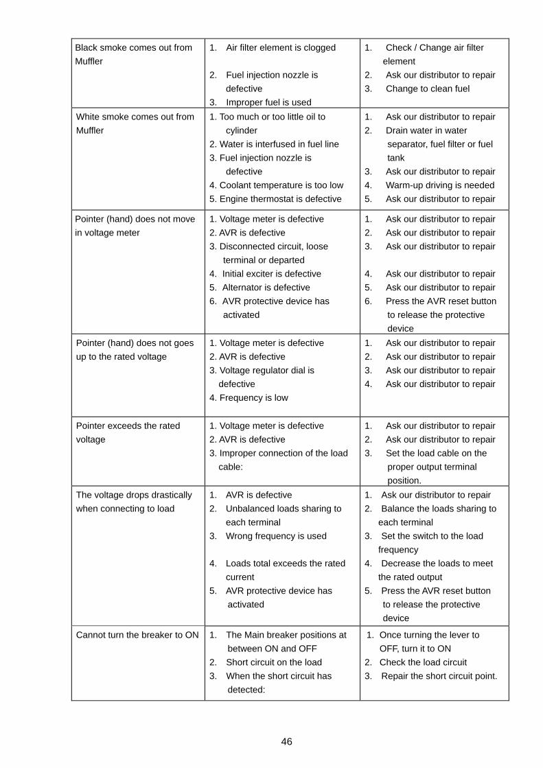
Black smoke comes out from
Muffler
1. Air filter element is clogged
2. Fuel injection nozzle is
defective
3. Improper fuel is used
1. Check / Change air filter
element
2. Ask our distributor to repair
3. Change to clean fuel
White smoke comes out from
Muffler
1. Too much or too little oil to
cylinder
2. Water is interfused in fuel line
3. Fuel injection nozzle is
defective
4. Coolant temperature is too low
5. Engine thermostat is defective
1. Ask our distributor to repair
2. Drain water in water
separator, fuel filter or fuel
tank
3. Ask our distributor to repair
4. Warm-up driving is needed
5. Ask our distributor to repair
Pointer (hand) does not move
in voltage meter
1. Voltage meter is defective
2. AVR is defective
3. Disconnected circuit, loose
terminal or departed
4. Initial exciter is defective
5. Alternator is defective
6. AVR protective device has
activated
1. Ask our distributor to repair
2. Ask our distributor to repair
3. Ask our distributor to repair
4. Ask our distributor to repair
5. Ask our distributor to repair
6. Press the AVR reset button
to release the protective
device
Pointer (hand) does not goes
up to the rated voltage
1. Voltage meter is defective
2. AVR is defective
3. Voltage regulator dial is
defective
4. Frequency is low
1. Ask our distributor to repair
2. Ask our distributor to repair
3. Ask our distributor to repair
4. Ask our distributor to repair
Pointer exceeds the rated
voltage
1. Voltage meter is defective
2. AVR is defective
3. Improper connection of the load
cable:
1. Ask our distributor to repair
2. Ask our distributor to repair
3. Set the load cable on the
proper output terminal
position.
The voltage drops drastically
when connecting to load
1. AVR is defective
2. Unbalanced loads sharing to
each terminal
3. Wrong frequency is used
4. Loads total exceeds the rated
current
5. AVR protective device has
activated
1. Ask our distributor to repair
2. Balance the loads sharing to
each terminal
3. Set the switch to the load
frequency
4. Decrease the loads to meet
the rated output
5. Press the AVR reset button
to release the protective
device
Cannot turn the breaker to ON 1. The Main breaker positions at
between ON and OFF
2. Short circuit on the load
3. When the short circuit has
detected:
1. Once turning the lever to
OFF, turn it to ON
2. Check the load circuit
3. Repair the short circuit point.
47
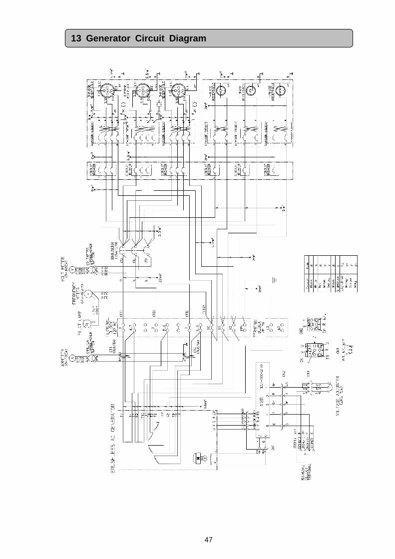
13 Generator Circuit Diagram
48
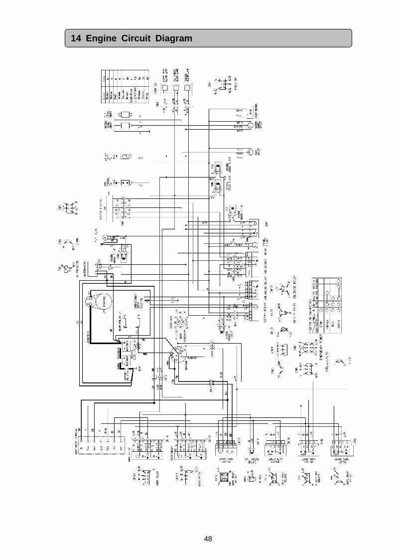
14 Engine Circuit Diagram


1
©2013


![Engine Oil[1]](https://img.pdfslide.net/doc/110x75/577ccd1f1a28ab9e788b9106/engine-oil1.jpg)