Embed Size (px)
Citation preview
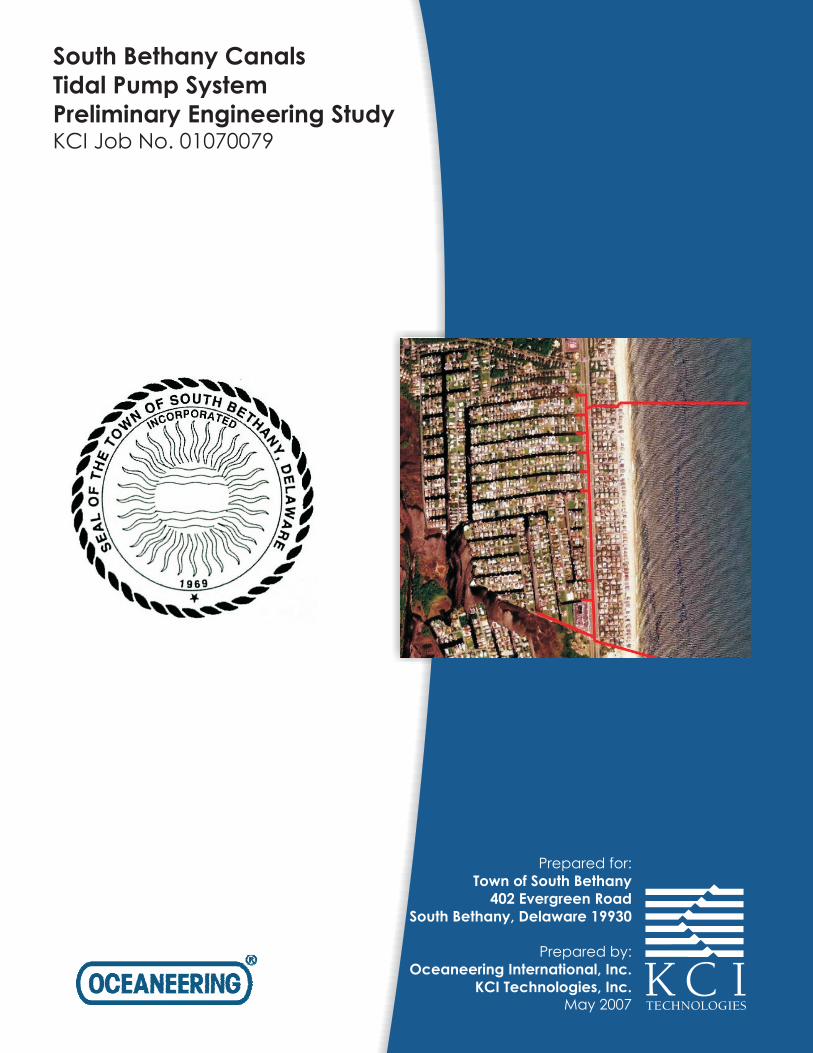
South Bethany Canals
Tidal Pump System
Preliminary Engineering StudyKCI Job No. 01070079
Prepared for:
Prepared by:
May 2007
Town of South Bethany
402 Evergreen Road
South Bethany, Delaware 19930
Oceaneering International, Inc.
KCI Technologies, Inc.
TOWN OF SOUTH BETHANY
402 EVERGREEN ROAD SOUTH BETHANY, DELAWARE 19930
SOUTH BETHANY CANALS TIDAL PUMP SYSTEM
PRELIMINARY ENGINEERING STUDY
Prepared by:
OCEANEERING INTERNATIONAL, INC.
700 Rosemont Ave. Chesapeake, Virginia 23324
KCI TECHNOLOGIES, INC. 10 North Park Drive
Hunt Valley, Maryland 21030
May 23, 2007
Town of South Bethany, Preliminary Engineering Study Delaware Tidal Pump System
KCI/OII i May 2007
EXECUTIVE SUMMARY
This preliminary engineering and budgetary cost study was undertaken to provide an analysis of all aspects of the proposed Tidal Pump System. The South Bethany Beach Tidal Pump (TP) System provides a design to utilize the existing tidal differential between the Atlantic Ocean and the canals of South Bethany to circulate water via a network of underground pipes connecting the two bodies of water. The circulation of the water is meant to improve the water quality within the canals. For the preliminary engineering and budgetary cost study OII/KCI performed a hydraulic analysis of the system; provided an analysis of environmental factors which may affect the TP system; addressed potential permitting requirements; provided an analysis of potential pipe materials, installation methods, valve types and locations; and Identified operations and maintenance issues. From this compiled information budgetary estimates and preliminary scheduling was developed. From the information gathered, OII/KCI recommends constructing the system as originally proposed with an extension of the south Intake/Outfall piping 1,600 feet offshore but without a check valve. The recommendations regarding the Tidal Pump system are as follows:
• All piping is to be HDPE.
• Canal feeder lines will include 2,026 feet of all 12” pipe. Installation of feeder lines is to be performed through trenchless methods for crossing Route 1. The remaining length may be installed via open trench or continuation of trenchless installation.
• The system will be configured with a 1,600-foot offshore intake/outfall 36” pipe located at both the north and south end of the system.
• The trunk line piping will include 5,010 feet of all 36” in addition to the offshore piping. Installation of the shore side elements of the trunk line is to be installed via open trench where possible. Road crossings are to be performed through horizontal directional drilling (HDD), microtunnelling or bore-and-jack method. HDD is recommended for installation along North 6th Street as well as through the beach crossing zone. Offshore installation is recommended to utilize HDD, float and sink, or dig and lay methods.
• There are to be a total of 12 manholes, one for each of the nine canals and one at each end of north 6th street as well as one associated with the south I/O pipe. All manholes are to be pre-cast concrete. Each manhole shall have a bolted on cap attached to the system piping for maintenance access.
• The system is to be fitted with 9 - 12” Canal feeder gate valves which are to be HDPE, located near the canal side manholes and are to be manually actuated.
• The system is to be fitted with 2 - 36” Ocean side gate valves which are to be copper-nickel and located near the ocean side manholes. These valves are to be automatically actuated with electric drive and a manual override.
• Both offshore I/O pipes will be fitted with a diffuser-like outfall with approximately 3 risers 3 feet to 5 feet above the seabed. The diffuser heads will be configured with wide ports to reduce intake and outfall velocities thus minimizing headloss.
• Maintenance of the system is to be based upon monitoring of system flow through a portable type propeller meter. Cleaning of the system is expected to be necessary at least
Town of South Bethany, Preliminary Engineering Study Delaware Tidal Pump System
KCI/OII ii May 2007
on an annual basis through a variety of potential means depending on the extent of fouling common to the water/ wastewater industry.
The environmental factors affecting the proposed system area do not present any specific technical problems for construction and operation. The wave climate along the coast is average for the Atlantic coast and thus will be within potential contractor abilities. OII/KCI recommends performing a full geotechnical investigation as part of the design to ascertain site conditions for the final system design. Marine fouling and potential sedimentation within the system were also identified as a significant factor in maintaining system performance. Corrosion of metallic components induced by the marine environment was noted as a reason to employ non-corrosive components where practical. To expedite permitting OII/KCI recommends communication with regulators as soon as possible to ascertain the exact permitting requirements that will be required. Easement issues were noted to be minimal for the project. The cost estimates for full engineering design services for the system are $249,000 with a probable construction cost estimate ranging from $5.2 to $6.7 million. The annual O&M estimate for the system is approximately $18,400. The preliminary project schedule includes approximately eight months for engineering design and permitting and an additional two months for bidding and contract award. Construction of the system is projected to take approximately 7 ½ months while confirmatory testing would take additional two months to complete.

Town of South Bethany, Preliminary Engineering Study Delaware Tidal Pump System
KCI/OII iii May 2007
TABLE OF CONTENTS
EXECUTIVE SUMMARY ............................................................................................................. i 1. INTRODUCTION ...............................................................................................................1 2. PROJECT BACKGROUND, SYSTEM DESCRIPTION AND EVALUATION..............1 3. ENVIRONMENTAL FACTORS......................................................................................17 4. PERMITTING REQUIREMENTS ...................................................................................23 5. PIPING MATERIALS.......................................................................................................27 6. INSTALLATION METHODS ..........................................................................................32 7. VALVE TYPES AND LOCATIONS ...............................................................................46 8. OPERATION AND MAINTENANCE.............................................................................49 9. BUDGETARY ESTIMATES............................................................................................52 10. PROJECT SCHEDULES ..................................................................................................53 11. CONCLUSION..................................................................................................................53
LIST OF TABLES
Table 2-1 Tidal Pump System Quantities – Original Configuration ............................................3 Table 2-2 Tidal Cycle Head Differential Analysis .......................................................................6 Table 2-3 Minor Loss Coefficient (K) Values ..............................................................................7 Table 2-4 Hydraulic Analysis Summary.......................................................................................9 Table 2-5 Hydraulic Analysis Configuration Comparison .........................................................10 Table 2-6 Minor Loss Coefficient Effects Analysis ...................................................................14 Table 2-7 Flushing Rate vs. Average Flow ................................................................................16 Table 5-1 Pipe Material Comparison..........................................................................................32 Table 6-1 Offshore Installation Method Comparison.................................................................38 Table 6-2 Intake/Outfall Configuration Comparison..................................................................46
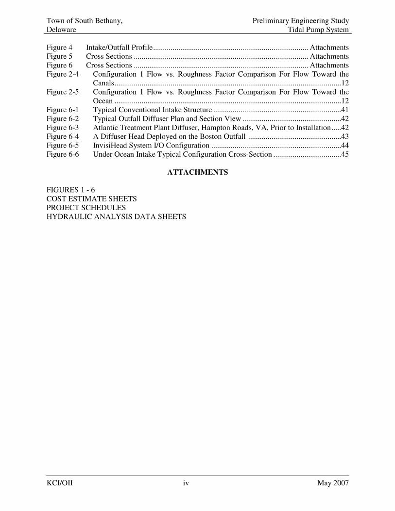
LIST OF FIGURES
Figure 1 Overview Plan .......................................................................................... Attachments Figure 2-1 Plan........................................................................................................... Attachments Figure 2-2 Plan........................................................................................................... Attachments Figure 2-3 Plan........................................................................................................... Attachments Figure 3 Profile ....................................................................................................... Attachments
Town of South Bethany, Preliminary Engineering Study Delaware Tidal Pump System
KCI/OII iv May 2007
Figure 4 Intake/Outfall Profile................................................................................ Attachments Figure 5 Cross Sections .......................................................................................... Attachments Figure 6 Cross Sections .......................................................................................... Attachments Figure 2-4 Configuration 1 Flow vs. Roughness Factor Comparison For Flow Toward the
Canals.....................................................................................................................12 Figure 2-5 Configuration 1 Flow vs. Roughness Factor Comparison For Flow Toward the
Ocean .....................................................................................................................12 Figure 6-1 Typical Conventional Intake Structure ..................................................................41 Figure 6-2 Typical Outfall Diffuser Plan and Section View ...................................................42 Figure 6-3 Atlantic Treatment Plant Diffuser, Hampton Roads, VA, Prior to Installation.....42 Figure 6-4 A Diffuser Head Deployed on the Boston Outfall ................................................43 Figure 6-5 InvisiHead System I/O Configuration ...................................................................44 Figure 6-6 Under Ocean Intake Typical Configuration Cross-Section ...................................45
ATTACHMENTS
FIGURES 1 - 6 COST ESTIMATE SHEETS PROJECT SCHEDULES HYDRAULIC ANALYSIS DATA SHEETS
Town of South Bethany, Preliminary Engineering Study Delaware Tidal Pump System
KCI/OII 1 May 2007
1. INTRODUCTION
This preliminary engineering report regarding the proposed Tidal Pump System for the South Bethany Canals has been prepared by Oceaneering International Inc. and KCI Technologies, Inc. (OII/KCI) as consultants to the Town of South Bethany, Delaware. This Preliminary Engineering Study will provide a preliminary basis of design for the proposed tidal pump system to include budgetary cost estimates for the design, permit acquisition, and construction as well as development of an overall project schedule for the major phases of the project. The study will also include identification of operations and maintenance requirements and costs of the proposed system. This information will be used to develop a Request for Proposal (RFP) adequate to issue to potential contractors to obtain proposals for the design and construction of this Tidal Pump System. This Preliminary Engineering Study will also provide information regarding the project requirements associated with the following subtopics; Environmental Factors, Piping Materials, Installation Methods, Pipe Section Joining, Valve Types and Locations, and Maintenance. 2. PROJECT BACKGROUND, SYSTEM DESCRIPTION AND EVALUATION
2.1 Project Background
In the early 1950s, construction began on the installation of a series of dead-end canals in the town of South Bethany Delaware. The purpose was to provide waterfront property to residential homes west of Route 1. The 5-mile system was completed in the 1970s. In recent years there have been concerns from the town and homeowners about the water quality in the canal system. The following assessment was issued in the 2003 Delaware/Maryland Canal Conference Proceedings: “At that time, thought was not given to the impact that the design, construction, and types of materials used to build the canals might have on the environment. In recent years, these canals have been experiencing many challenges to their ecosystems such as poor circulation and flushing, excessive nutrients, low dissolved oxygen levels, hydrogen sulfide, fish kills, odiferous and unsightly algae, navigational problems due to turbid waters, declining benthic, shellfish and crab communities, stagnant, polluted waters, harmful algal blooms, and more.”(Delaware/Maryland
Dead-End Canal Conference Proceedings: Challenges and Solutions 17 May 2003) In 2002 Lloyd Hughes, a former South Bethany Councilman and retired engineer began researching the development of a system to flush and circulate the canals. Lloyd determined the main issues of poor water quality were:
• Low dissolved oxygen • High nutrients • High bacteria • Algae blooms • Poor species diversity and almost no fish life • Obnoxious odors
Town of South Bethany, Preliminary Engineering Study Delaware Tidal Pump System
KCI/OII 2 May 2007
In November 2003 after further development, Lloyd Hughes presented his Tidal Pump design to the town of South Bethany.
2.2 System Description
The Tidal Pump is a simple design utilizing the tides to move canal water to the Atlantic Ocean and then return clean seawater to the dead end canals of South Bethany via a network of underground pipes connecting the two bodies of water. Utilizing the natural forces of gravity, water would flow from the body of water having the higher tide. Since the tidal heights of both bodies of water are diametrically opposite, water will alternately flow back and forth without using any outside source of man-made energy. South Bethany’s Canal Mean Tide Level, fed by the back bays and their fresh water inland streams, is 0.66 feet (8”) above Mean Sea Level; compared to the Atlantic Ocean Mean Tide Level which is at Mean Sea Level. This would cause the average water flow from the canal to the ocean to be greater than the return flow. Based on normal conditions, water would flow approximately 15 hours a day to the ocean, while the return flow from the ocean will be approximately 9 hours. These flow rates are based on each tide cycle being approximately 6 hours and 12 minutes. Canal-to-ocean flushing would occur in less than 2 days while ocean-to-canal flushing will take about 14 days. Flushing calculations are based on displacing 70 to 75 percent of the total water volume in the dead end canals of South Bethany. Based on preliminary hydraulics and alignment investigations performed during the previous evaluation a pipeline system was developed interconnecting the canals and ocean. In order to ensure adequate water flow, a continuous 6,700-feet-long, 36” diameter pipe, trunk line would run from 1,600 feet offshore, at the north end of South Bethany under North Sixth Street, to the Route 1 highway median strip. The pipeline would then turn south under the median strip to Fenwick Island State Park where it would run towards the ocean terminating 50 feet offshore. This main trunk line would serve nine feeder lines connected to the dead end canals. Eight of the feeder lines would be approximately 120 feet in length and service all except the York Canal. The feeder for the York canal would be about 900 feet in length. Each feeder line would be 12” in diameter. Each feeder line would connect the main trunk line located in the median strip to the end of each canal. All of the pipelines would be placed horizontally at approximately 4 feet below mean sea level. The northern portion of the trunk line would serve as an intake/outfall port while the southern portion will be for outfall only. The outfall of the southern trunk line would have a one-way valve to discharge canal water into the ocean and to restrict flow from the ocean from coming back into the canals. (see Figure 1 in Attachments)
Town of South Bethany, Preliminary Engineering Study Delaware Tidal Pump System
KCI/OII 3 May 2007
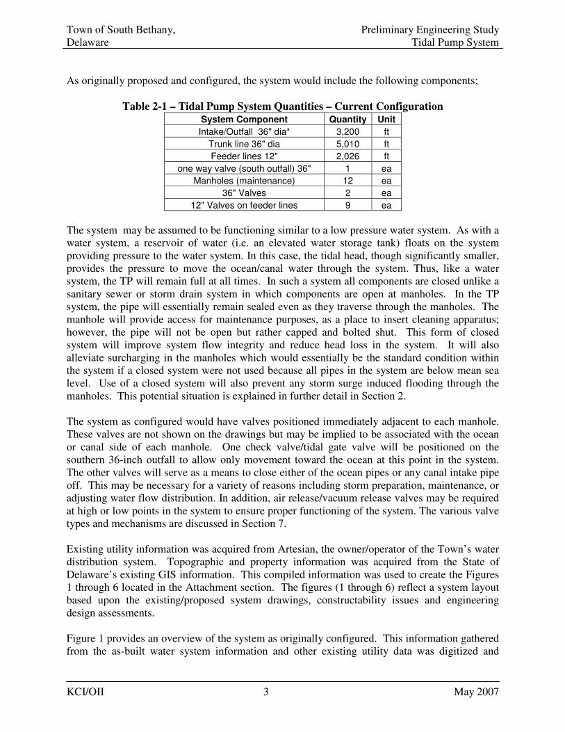
As originally proposed and configured, the system would include the following components;
Table 2-1 – Tidal Pump System Quantities – Current Configuration
System Component Quantity Unit
Intake/Outfall 36" dia* 3,200 ft
Trunk line 36" dia 5,010 ft
Feeder lines 12" 2,026 ft
one way valve (south outfall) 36" 1 ea
Manholes (maintenance) 12 ea
36" Valves 2 ea
12" Valves on feeder lines 9 ea
The system may be assumed to be functioning similar to a low pressure water system. As with a water system, a reservoir of water (i.e. an elevated water storage tank) floats on the system providing pressure to the water system. In this case, the tidal head, though significantly smaller, provides the pressure to move the ocean/canal water through the system. Thus, like a water system, the TP will remain full at all times. In such a system all components are closed unlike a sanitary sewer or storm drain system in which components are open at manholes. In the TP system, the pipe will essentially remain sealed even as they traverse through the manholes. The manhole will provide access for maintenance purposes, as a place to insert cleaning apparatus; however, the pipe will not be open but rather capped and bolted shut. This form of closed system will improve system flow integrity and reduce head loss in the system. It will also alleviate surcharging in the manholes which would essentially be the standard condition within the system if a closed system were not used because all pipes in the system are below mean sea level. Use of a closed system will also prevent any storm surge induced flooding through the manholes. This potential situation is explained in further detail in Section 2. The system as configured would have valves positioned immediately adjacent to each manhole. These valves are not shown on the drawings but may be implied to be associated with the ocean or canal side of each manhole. One check valve/tidal gate valve will be positioned on the southern 36-inch outfall to allow only movement toward the ocean at this point in the system. The other valves will serve as a means to close either of the ocean pipes or any canal intake pipe off. This may be necessary for a variety of reasons including storm preparation, maintenance, or adjusting water flow distribution. In addition, air release/vacuum release valves may be required at high or low points in the system to ensure proper functioning of the system. The various valve types and mechanisms are discussed in Section 7. Existing utility information was acquired from Artesian, the owner/operator of the Town’s water distribution system. Topographic and property information was acquired from the State of Delaware’s existing GIS information. This compiled information was used to create the Figures 1 through 6 located in the Attachment section. The figures (1 through 6) reflect a system layout based upon the existing/proposed system drawings, constructability issues and engineering design assessments. Figure 1 provides an overview of the system as originally configured. This information gathered from the as-built water system information and other existing utility data was digitized and
Town of South Bethany, Preliminary Engineering Study Delaware Tidal Pump System
KCI/OII 4 May 2007
placed on Figures 2-1, 2-2 and 2-3 within the areas where the Tidal Pump (TP) system could be constructed to ascertain potential utility conflicts. Figures 5 and 6 present typical cross sections along the projected alignment near Route 1. The cross sections were generated to provide a cursory analysis of potential utility conflicts within the system which may be encountered during the design phase of the project. These profiles were generated for the Route 1 corridor of the project at York Road, North 6th Street, Layton Canal, and Boone Canal. The analysis indicated generally that the only potential utility conflict may occur with the existing sanitary sewer which will have to be crossed by the 12-inch feeder lines. This sanitary sewer is a 12-inch diameter gravity pipeline which varies in depth as it flows northward. Thus the depth of the sewer will provide possible conflict with the 12-inch feeder line near the Boone Canal (see Attached Figure 5). This conflict can be resolved simply by varying the attachment point of the feeder line to the 36-inch trunk line. Additionally, if installed via HDD the line could be dipped to cross under or over the existing sewer. Either of these variations will not affect system performance due to the system operational condition of being fully flooded at all times. The exact configuration at this point will be ascertained during the design phase of the project based upon survey information. Additional sewer crossing issues may exist with the 12-inch feeder to the York Canal. It is anticipated that these issues may also be addressed by varying the connection elevation to the trunk line and should not cause significant variation to the project alignment.
2.3 Hydraulic Evaluation
As part of the evaluation process of the TP system, the Town, in 2005, retained Entrix, Inc. and J.E. Edinger Associates, Inc. to perform a residence time analysis of the proposed TP design. The team evaluated the system using the existing Generalized Environmental Modeling Surface Water System (GEMSS) model. The model was used to produce a computational simulation of a dye study to examine the potential benefits of increasing flushing into the system. The model included actual tidal cycles based upon historic data as well as other recorded environmental data. The model evaluation results were said to indicate a “strong likelihood” that the proposed pipe design will significantly increase the flushing exchange rate between the South Bethany Canals and ocean water. However, the actual hydraulic evaluation of the piping within the GEMSS model was based upon utilizing the Hazen-Williams equation and a roughness coefficient, based on a Chezy coefficient, of 20 for all channels and pipes. According to members of the Entrix team the Hazen Williams friction factor utilized in their equations was 150 which equates to essentially a newly installed plastic (smooth surface) pipe. To further verify the TP concept, KCI/OII conducted a hydraulic analysis to evaluate possible reductions in system capacity resulting from potential marine fouling or other occurrences which may reduce the pipe flow capacity. In addition, the modeling was conducted to ascertain the viability of alternative system configurations. The team utilized WaterCAD modeling software, developed by Bentley Systems Inc., to perform the evaluation.
Town of South Bethany, Preliminary Engineering Study Delaware Tidal Pump System
KCI/OII 5 May 2007
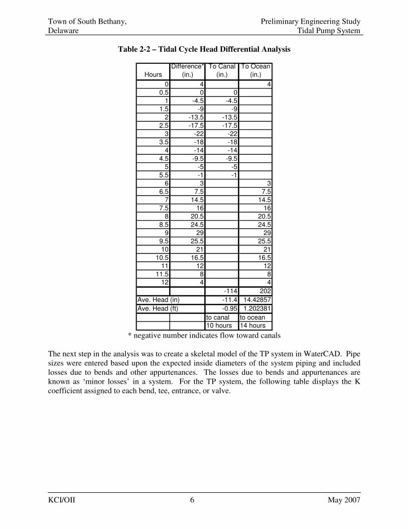
WaterCAD is the industry-wide definitive model used for modeling complex pressurized pipe networks. WaterCAD has been in existence for many years and is has been updated several times to stay current with improving computer technology. WaterCAD numerical computations are based on research conducted by the U.S. Environmental Protection Agency Drinking Water Research Division as well as other organizations. The current version of the software is Version 8. Bentley Systems Inc. provides training and certification for the use of WaterCAD and the OII/KCI team currently employs several individuals so certified who currently use WaterCAD Version 7. WaterCAD utilizes a variety of equations for a variety of conditions. For the TP system the Hazen-Williams equation was used as the basis for the modeling analysis. The Hazen-Williams equation was first developed in the 1906 and is currently the most commonly used equation for modeling water systems. It is considered most effective in modeling lower flow velocities, such as are projected in the TP system. WaterCAD as a hydraulic modeling tool is used in water system design projects to determine pipe flow, pipe and fitting sizes, pressures, grades, and other hydraulic related parameters. WaterCAD was chosen because essentially the TP project resembles water system design with various water sources. The ocean and canals were set as reservoirs, depicting water sources at an instantaneous head elevation. The model was used to determine various flows at the canal and ocean inlet/outfall based on a fixed tide condition in combination with other factors such as pipe roughness, pipe age, and marine growth within the pipe lines. It should be noted, the WaterCAD model was created to model instantaneous flow through the TP system, it was not meant to model the dispersion and mixing of the canal waters. This function was performed by the GEMSS model and canal flow was not part of this evaluation. The WaterCAD model however is an effective tool for modeling variable hydraulic flow conditions which may occur within the TP system. The model created for this analysis also provides an efficient way to evaluate flow differences created through different system configurations. As noted above, this evaluation was conducted to ascertain instantaneous flow through the system. To accomplish this, typical head differential to be expected on a daily basis in both flow directions were established through a cursory tidal analysis. This tidal analysis was performed on a linear interpretation of a single tidal cycle and is not prescribed to be a precise analysis of the tidal variability. In addition, the tidal cycle length was approximated at 12 hours instead of 12 hours 24 minutes. This analysis provides a basis which can be considered proximate to a point on a typical tidal cycle South Bethany may experience and provides a numerical basis with which to compare different system configurations. The results of the linear interpretation of a tidal cycle are included in Table 2-2 below. This information was calculated from existing tidal data which shows that the average flow towards the canals would have a head differential of 11.4 inches while the average flow per hour going toward the ocean would have a head differential of 14.4 inches. For the model run analysis, a more conservative head variation was established at 7.2 inches (63% of average) going toward the canals, while 10.9 inches (76% of average) was used for flow toward the ocean prorated from the above noted tidal head differential.
Town of South Bethany, Preliminary Engineering Study Delaware Tidal Pump System
KCI/OII 6 May 2007
Table 2-2 – Tidal Cycle Head Differential Analysis
Hours
Difference*
(in.)
To Canal
(in.)
To Ocean
(in.)
0 4 4
0.5 0 0
1 -4.5 -4.5
1.5 -9 -9
2 -13.5 -13.5
2.5 -17.5 -17.5
3 -22 -22
3.5 -18 -18
4 -14 -14
4.5 -9.5 -9.5
5 -5 -5
5.5 -1 -1
6 3 3
6.5 7.5 7.5
7 14.5 14.5
7.5 16 16
8 20.5 20.5
8.5 24.5 24.5
9 29 29
9.5 25.5 25.5
10 21 21
10.5 16.5 16.5
11 12 12
11.5 8 8
12 4 4
-114 202
Ave. Head (in) -11.4 14.42857
Ave. Head (ft) -0.95 1.202381
to canal to ocean
10 hours 14 hours * negative number indicates flow toward canals
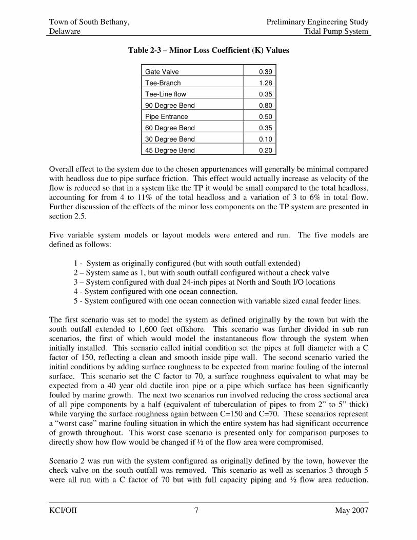
The next step in the analysis was to create a skeletal model of the TP system in WaterCAD. Pipe sizes were entered based upon the expected inside diameters of the system piping and included losses due to bends and other appurtenances. The losses due to bends and appurtenances are known as ‘minor losses’ in a system. For the TP system, the following table displays the K coefficient assigned to each bend, tee, entrance, or valve.
Town of South Bethany, Preliminary Engineering Study Delaware Tidal Pump System
KCI/OII 7 May 2007
Table 2-3 – Minor Loss Coefficient (K) Values
Gate Valve 0.39
Tee-Branch 1.28
Tee-Line flow 0.35
90 Degree Bend 0.80
Pipe Entrance 0.50
60 Degree Bend 0.35
30 Degree Bend 0.10
45 Degree Bend 0.20
Overall effect to the system due to the chosen appurtenances will generally be minimal compared with headloss due to pipe surface friction. This effect would actually increase as velocity of the flow is reduced so that in a system like the TP it would be small compared to the total headloss, accounting for from 4 to 11% of the total headloss and a variation of 3 to 6% in total flow. Further discussion of the effects of the minor loss components on the TP system are presented in section 2.5. Five variable system models or layout models were entered and run. The five models are defined as follows:
1 - System as originally configured (but with south outfall extended) 2 – System same as 1, but with south outfall configured without a check valve 3 – System configured with dual 24-inch pipes at North and South I/O locations 4 - System configured with one ocean connection. 5 - System configured with one ocean connection with variable sized canal feeder lines.
The first scenario was set to model the system as defined originally by the town but with the south outfall extended to 1,600 feet offshore. This scenario was further divided in sub run scenarios, the first of which would model the instantaneous flow through the system when initially installed. This scenario called initial condition set the pipes at full diameter with a C factor of 150, reflecting a clean and smooth inside pipe wall. The second scenario varied the initial conditions by adding surface roughness to be expected from marine fouling of the internal surface. This scenario set the C factor to 70, a surface roughness equivalent to what may be expected from a 40 year old ductile iron pipe or a pipe which surface has been significantly fouled by marine growth. The next two scenarios run involved reducing the cross sectional area of all pipe components by a half (equivalent of tuberculation of pipes to from 2” to 5” thick) while varying the surface roughness again between C=150 and C=70. These scenarios represent a “worst case” marine fouling situation in which the entire system has had significant occurrence of growth throughout. This worst case scenario is presented only for comparison purposes to directly show how flow would be changed if ½ of the flow area were compromised. Scenario 2 was run with the system configured as originally defined by the town, however the check valve on the south outfall was removed. This scenario as well as scenarios 3 through 5 were all run with a C factor of 70 but with full capacity piping and ½ flow area reduction.
Town of South Bethany, Preliminary Engineering Study Delaware Tidal Pump System
KCI/OII 8 May 2007
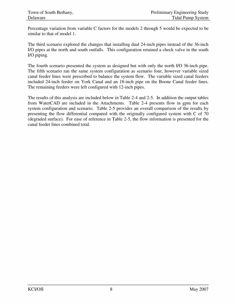
Percentage variation from variable C factors for the models 2 through 5 would be expected to be similar to that of model 1. The third scenario explored the changes that installing dual 24-inch pipes instead of the 36-inch I/O pipes at the north and south outfalls. This configuration retained a check valve in the south I/O piping. The fourth scenario presented the system as designed but with only the north I/O 36-inch pipe. The fifth scenario ran the same system configuration as scenario four, however variable sized canal feeder lines were prescribed to balance the system flow. The variable sized canal feeders included 24-inch feeder on York Canal and an 18-inch pipe on the Boone Canal feeder lines. The remaining feeders were left configured with 12-inch pipes. The results of this analysis are included below in Table 2-4 and 2-5. In addition the output tables from WaterCAD are included in the Attachments. Table 2-4 presents flow in gpm for each system configuration and scenario. Table 2-5 provides an overall comparison of the results by presenting the flow differential compared with the originally configured system with C of 70 (degraded surface). For ease of reference in Table 2-5, the flow information is presented for the canal feeder lines combined total.
Town of South Bethany, Preliminary Engineering Study Delaware Tidal Pump System
KCI/OII 9 May 2007
Table 2-4 Hydraulic Analysis Summary
Config. Description Flow Dir. Pipe C Ocean Flow (gpm)/Vel.(fps) @ Canal Canal
Flow to: Diameter Value Total gpm Total gpm
1 Check Valve @ South Ocean Pipe Ocean Half 70 975 0.61 891 0.56 1866 163 0.92 238 1.35 226 1.28 225 1.27 223 1.26 225 1.27 266 1.51 204 1.15 97 0.55 1867
Flow % 52.3% 47.7% 8.7% 12.7% 12.1% 12.1% 11.9% 12.1% 14.2% 10.9% 5.2%
1 Check Valve @ South Ocean Pipe Ocean Full 70 2366 0.75 2168 0.68 4534 404 1.15 574 1.63 548 1.56 545 1.54 542 1.54 544 1.54 637 1.81 497 1.41 240 0.68 4531
Flow % 52.2% 47.8% 8.9% 12.7% 12.1% 12.0% 12.0% 12.0% 14.1% 11.0% 5.3%
1 Check Valve @ South Ocean Pipe Canals Half 70 917 0.58 0 0 917 100 0.57 142 0.81 125 0.71 116 0.65 108 0.61 104 0.59 107 0.61 79 0.45 34 0.19 915
Flow % 100.0% 0.0% 10.9% 15.5% 13.7% 12.7% 11.8% 11.4% 11.7% 8.6% 3.7%
1 Check Valve @ South Ocean Pipe Canals Full 70 2244 0.71 0 0 2244 249 0.71 344 0.98 305 0.86 282 0.8 265 0.75 255 0.72 262 0.74 196 0.56 87 0.25 2245
Flow % 100.0% 0.0% 11.1% 15.3% 13.6% 12.6% 11.8% 11.4% 11.7% 8.7% 3.9%
1 Check Valve @ South Ocean Pipe Ocean Half 97 1306 0.82 1197 0.75 2503 227 1.28 316 1.79 302 1.71 300 1.7 299 1.69 300 1.7 349 1.97 275 1.56 135 0.76 2503
Flow % 52.2% 47.8% 9.1% 12.6% 12.1% 12.0% 11.9% 12.0% 13.9% 11.0% 5.4%
1 Check Valve @ South Ocean Pipe Ocean Full 97 3120 0.98 2872 0.91 5992 563 1.6 749 2.13 720 2.04 716 2.03 713 2.02 716 2.03 817 2.32 663 1.88 335 0.95 5992
Flow % 52.1% 47.9% 9.4% 12.5% 12.0% 11.9% 11.9% 11.9% 13.6% 11.1% 5.6%
1 Check Valve @ South Ocean Pipe Canals Half 97 1245 0.78 0 0 1245 139 0.79 189 1.07 168 0.95 156 0.88 147 0.83 142 0.8 145 0.82 110 0.62 50 0.28 1246
Flow % 100.0% 0.0% 11.2% 15.2% 13.5% 12.5% 11.8% 11.4% 11.6% 8.8% 4.0%
1 Check Valve @ South Ocean Pipe Canals Full 97 3017 0.95 0 0 3017 345 0.98 450 1.28 403 1.14 375 1.06 354 1 343 0.97 348 0.99 271 0.77 127 0.36 3016
Flow % 100.0% 0.0% 11.4% 14.9% 13.4% 12.4% 11.7% 11.4% 11.5% 9.0% 4.2%
1 Check Valve @ South Ocean Pipe Ocean Half 123 1591 1 1465 0.92 3056 288 1.63 382 2.16 367 2.08 365 2.06 363 2.06 365 2.06 416 2.35 339 1.91 171 0.97 3056
Flow % 52.1% 47.9% 9.4% 12.5% 12.0% 11.9% 11.9% 11.9% 13.6% 11.1% 5.6%
1 Check Valve @ South Ocean Pipe Ocean Full 123 3743 1.18 3465 1.09 7208 712 2.02 889 2.52 860 2.44 855 2.43 852 2.42 855 2.43 955 2.71 803 2.28 425 1.21 7206
Flow % 51.9% 48.1% 9.9% 12.3% 11.9% 11.9% 11.8% 11.9% 13.3% 11.1% 5.9%
1 Check Valve @ South Ocean Pipe Canals Half 123 1541 0.97 0 0 1541 177 1 229 1.3 206 1.16 191 1.08 181 1.02 175 0.99 178 1 139 0.79 65 0.37 1541
Flow % 100.0% 0.0% 11.5% 14.9% 13.4% 12.4% 11.7% 11.4% 11.6% 9.0% 4.2%
1 Check Valve @ South Ocean Pipe Canals Full 123 3692 1.16 0 0 3692 436 1.24 536 1.52 485 1.38 454 1.29 431 1.22 418 1.19 422 1.2 341 0.97 168 0.48 3691
Flow % 100.0% 0.0% 11.8% 14.5% 13.1% 12.3% 11.7% 11.3% 11.4% 9.2% 4.6%
1 Check Valve @ South Ocean Pipe Ocean Half 150 1852 1.16 1714 1.08 3566 351 1.98 441 2.49 426 2.41 423 2.39 422 2.39 423 2.39 474 2.68 397 2.25 209 1.18 3566
Flow % 51.9% 48.1% 9.8% 12.4% 11.9% 11.9% 11.8% 11.9% 13.3% 11.1% 5.9%
1 Check Valve @ South Ocean Pipe Ocean Full 150 4288 1.35 3997 1.26 8285 861 2.44 1008 2.86 980 2.78 975 2.77 973 2.76 976 2.77 1069 3.03 927 2.63 517 1.47 8286
Flow % 51.8% 48.2% 10.4% 12.2% 11.8% 11.8% 11.7% 11.8% 12.9% 11.2% 6.2%
1 Check Valve @ South Ocean Pipe Canals Half 150 1824 1.15 0 0 1824 215 1.21 266 1.5 240 1.36 225 1.27 213 1.2 207 1.17 209 1.18 168 0.95 82 0.47 1825
Flow % 100.0% 0.0% 11.8% 14.6% 13.2% 12.3% 11.7% 11.3% 11.5% 9.2% 4.5%
1 Check Valve @ South Ocean Pipe Canals Full 150 4319 1.36 0 0 4319 528 1.5 611 1.73 558 1.58 525 1.49 500 1.42 487 1.38 488 1.39 409 1.16 213 0.6 4319
Flow % 100.0% 0.0% 12.2% 14.1% 12.9% 12.2% 11.6% 11.3% 11.3% 9.5% 4.9%
Flow (gpm)/Vel.(fps) @ Ocean
North Outfall South Outfall Anchorage Petherton Brandywine Henlopen New Castle Layton May Boone York
Town of South Bethany, Preliminary Engineering Study Delaware Tidal Pump System
KCI/OII 10 May 2007
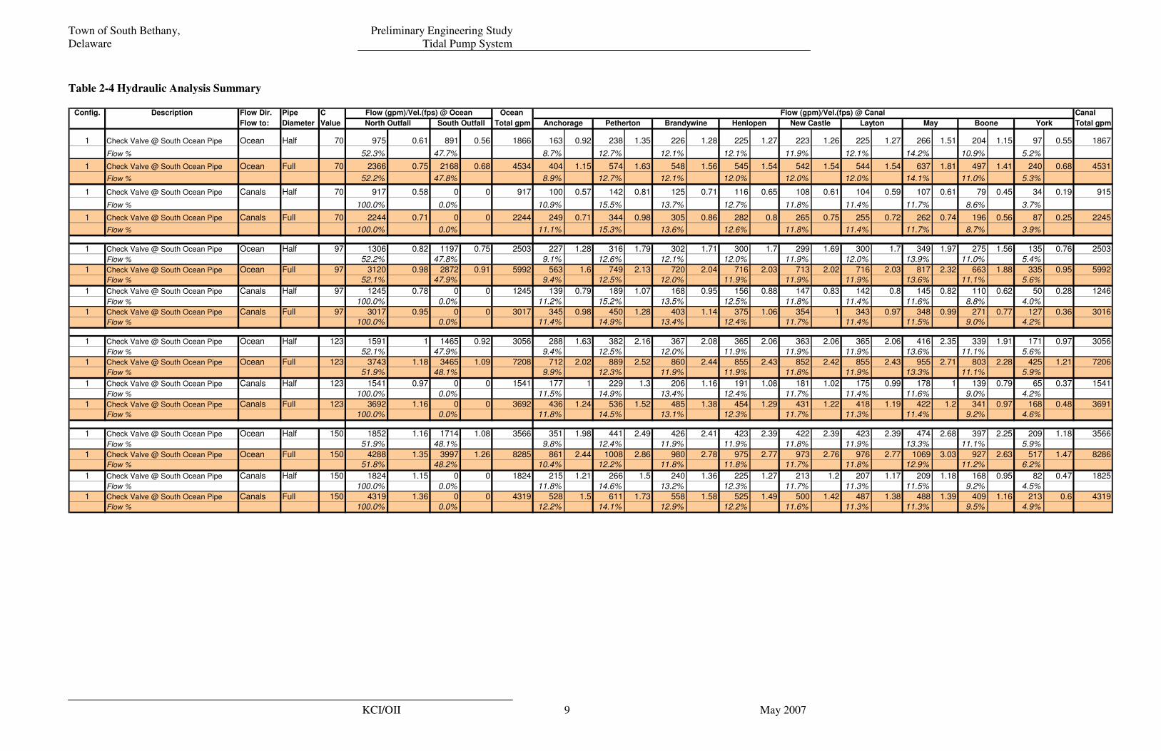
Table 2-4 Hydraulic Analysis Summary (Continued)
Config. Description Flow Dir Pipe C Ocean Flow (gpm)/Vel.(fps) @ Canal Canal
Flow to: Diameter Value Total gpm Total gpm
2 No Check Valve @ South Ocean pipe Ocean Half 70 975 0.61 891 0.56 1866 163 0.92 238 1.35 226 1.28 225 1.27 223 1.26 225 1.27 266 1.51 204 1.15 97 0.55 1867
Flow % 52% 48% 8.7% 12.7% 12.1% 12.1% 11.9% 12.1% 14.2% 10.9% 5.2% 100.0%
2 No Check Valve @ South Ocean pipe Ocean Full 70 2366 0.75 2167 0.68 4533 404 1.15 574 1.63 548 1.56 545 1.54 542 1.54 544 1.54 637 1.81 497 1.41 240 0.68 4531Flow % 52% 48% 8.9% 12.7% 12.1% 12.0% 12.0% 12.0% 14.1% 11.0% 5.3% 100.0%
2 No Check Valve @ South Ocean pipe Canals Half 70 780 0.49 713 0.45 1493 130 0.73 190 1.08 181 1.02 180 1.02 179 1.01 180 1.02 213 1.21 163 0.92 77 0.44 1493
Flow % 52% 48% 8.7% 12.7% 12.1% 12.1% 12.0% 12.1% 14.3% 10.9% 5.2% 100.0%
2 No Check Valve @ South Ocean pipe Canals Full 70 1893 0.6 1733 0.55 3626 323 0.92 460 1.3 439 1.24 436 1.24 434 1.23 436 1.24 511 1.45 398 1.13 192 0.54 3629Flow % 52% 48% 8.9% 12.7% 12.1% 12.0% 12.0% 12.0% 14.1% 11.0% 5.3% 100.0%
3 Two-24" Pipe at Ocean North & South Ocean Half 70 408+405 0.57 386+382 0.54 1581 137 0.78 201 1.14 191 1.08 190 1.08 189 1.07 190 1.08 227 1.28 173 0.98 82 0.46 1580
Flow % 51% 49% 8.7% 12.7% 12.1% 12.0% 12.0% 12.0% 14.4% 10.9% 5.2% 100.0%
3 Two-24" Pipe at Ocean North & South Ocean Full 70 999+989 0.7 944+935 0.66 3867 343 0.97 489 1.39 467 1.33 464 1.32 462 1.31 464 1.32 546 1.55 426 1.21 206 0.58 3867Flow % 51% 49% 8.9% 12.6% 12.1% 12.0% 11.9% 12.0% 14.1% 11.0% 5.3% 100.0%
3 Two-24" Pipe at Ocean North & South Canals Half 70 366+363 0.52 0+0 0 729 80 0.45 113 0.64 100 0.56 92 0.52 86 0.49 83 0.47 86 0.48 63 0.35 27 0.15 730
Flow % 100% 0% 11.0% 15.5% 13.7% 12.6% 11.8% 11.4% 11.8% 8.6% 3.7% 100.0%
3 Two-24" Pipe at Ocean North & South Canals Full 70 903+894 0.63 0+0 0 1797 199 0.56 276 0.78 244 0.69 226 0.64 212 0.6 205 0.58 210 0.59 157 0.44 70 2 1799Flow % 100% 0% 11.1% 15.3% 13.6% 12.6% 11.8% 11.4% 11.7% 8.7% 3.9% 100.0%
4 Only One 36" North I/O Pipe at Ocean Ocean Half 70 1148 0.72 N/A N/A 1148 126 0.71 178 1 157 0.9 145 0.82 136 0.77 131 0.74 134 0.76 99 0.56 43 0.24 1149
Flow % 100% 11.0% 15.5% 13.7% 12.6% 11.8% 11.4% 11.7% 8.6% 3.7% 100.0%
4 Only One 36" North I/O Pipe at Ocean Ocean Full 70 2807 0.88 N/A N/A 2807 311 0.88 430 1.22 381 1.08 353 1 331 0.94 319 0.91 327 0.93 245 0.7 110 0.31 2807Flow % 100% 11.1% 15.3% 13.6% 12.6% 11.8% 11.4% 11.6% 8.7% 3.9% 100.0%
4 Only One 36" North I/O Pipe at Ocean Canals Half 70 917 0.58 N/A N/A 917 100 0.57 142 0.81 125 0.71 116 0.65 108 0.61 104 0.59 107 0.61 79 0.45 34 0.19 915
Flow % 100% 10.9% 15.5% 13.7% 12.7% 11.8% 11.4% 11.7% 8.6% 3.7% 100.0%
4 Only One 36" North I/O Pipe at Ocean Canals Full 70 2244 0.71 N/A N/A 2244 249 0.71 344 0.98 305 0.86 282 0.8 265 0.75 255 0.72 262 0.74 196 0.56 87 0.25 2245Flow % 100% 11.1% 15.3% 13.6% 12.6% 11.8% 11.4% 11.7% 8.7% 3.9% 100.0%
5 Only One 36" North I/O Pipe at Ocean Ocean Half 70 1172 0.74 N/A N/A 1172 119 0.67 167 0.95 144 0.81 128 0.72 115 0.65 106 0.6 85 0.48 161 0.41 147 0.21 1172
Flow % 100% 10.2% 14.2% 12.3% 10.9% 9.8% 9.0% 7.3% 13.7% 12.5%
5 Only One 36" North I/O Pipe at Ocean Ocean Full 70 2871 0.91 N/A N/A 2871 294 0.84 403 1.14 347 1 310 0.88 280 0.79 259 0.73 206 0.59 399 0.5 373 0.26 2871Flow % 100% 10.2% 14.0% 12.1% 10.8% 9.8% 9.0% 7.2% 13.9% 13.0% 100.0%
5 Only One 36" North I/O Pipe at Ocean Canals Half 70 937 0.59 N/A N/A 937 95 0.54 134 0.76 115 0.65 102 0.58 92 0.52 85 0.48 68 0.38 129 0.33 117 0.17 937
Flow % 100% 10.1% 14.3% 12.3% 10.9% 9.8% 9.1% 7.3% 13.8% 12.5% 100.0%
5 Only One 36" North I/O Pipe at Ocean Canals Full 70 2295 0.72 N/A N/A 2295 235 0.67 322 0.91 278 0.79 248 0.7 224 0.63 207 0.59 165 0.47 319 0.4 297 0.21 2295Flow % 100% 10.2% 14.0% 12.1% 10.8% 9.8% 9.0% 7.2% 13.9% 12.9% 100.0%
North Outfall South Outfall Anchorage
Flow (gpm)/Vel.(fps) @ Ocean
Petherton Brandywine Henlopen New Castle Layton May Boone York
Table 2-5 Hydraulic Analysis Configuration Comparison
Config. Description Flow Dir Pipe C
Flow to: Diameter Value Total gpm Total gpm % change Total gpm % change Total gpm % change Total gpm % change Total gpm % change Total gpm % change Total gpm % change
1 Check Valve @ South Ocean Pipe Ocean Half 70 1867 2503 134.1% 3056 163.7% 3566 191.0% 1867 100.0% 1580 84.6% 1149 61.5% 1172 62.8%
1 Check Valve @ South Ocean Pipe Ocean Full 70 4531 5992 132.2% 7206 159.0% 8286 182.9% 4531 100.0% 3867 85.3% 2807 62.0% 2871 63.4%
1 Check Valve @ South Ocean Pipe Canals Half 70 915 1246 136.2% 1541 168.4% 1825 199.5% 1493 163.2% 730 79.8% 915 100.0% 937 102.4%
1 Check Valve @ South Ocean Pipe Canals Full 70 2245 3016 134.3% 3691 164.4% 4319 192.4% 3629 161.6% 1799 80.1% 2245 100.0% 2295 102.2%
Configuration 3 Configuration 4 Configuration 5Config 1; C=97 Config 1; C=123 Config 1; C=150 Configuration 2
Note: % change is as compared to Configuration 1, C=70 Scenario,Total gpm is flow through all Canal feeder piping combined.
Town of South Bethany, Preliminary Engineering Study Delaware Tidal Pump System
KCI/OII 11 May 2007
2.4 Hydraulic Evaluation Results
2.4.1 Configuration 1
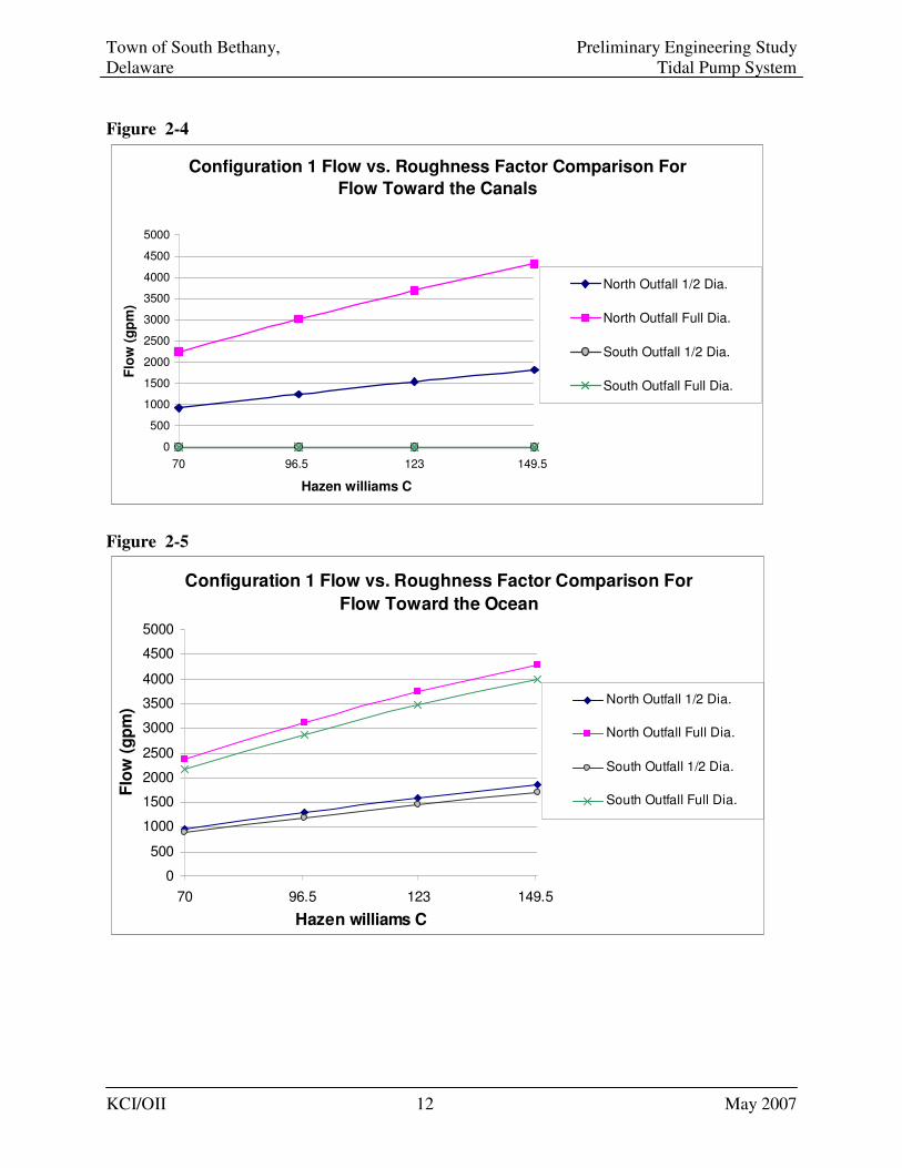
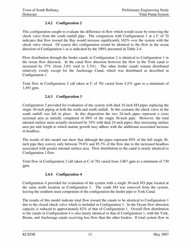
The results of the analysis indicate several points. First in looking at the system Configuration 1, the marine growth which would tend to cause the surface of the pipe to become significantly more rough (C factor change from 150 to 70) would reduce flow in the system by an average of 48%. Secondly, in a comparison of initial condition to worst case scenario, in which ½ of the cross sectional area and the C factor changes from 150 to 70, the system would loose approximately 78% of its conveyance capacity. Total flow in Configuration 1 varied from 8,200 gpm to a minimum of 915 gpm worst case scenario. Analysis of flow distribution through the feeder canals is also presented in the Table 2-4. In general, flow in the feeder canals is relatively well balanced in each scenario of Configuration 1. The noted exception is for the flow in the York Canal which is approximately ½ the flow in the other feeder lines. Then Anchorage Canal also displays flow lower than the other feeders by approximately 50% (8% vs. 12%). Variation in the C value causes only minor changes to flow distribution in the canal feeder piping. Comparison of the variation in performance versus C factor was also graphically analyzed for Configuration 1. The results of the analysis are presented in Figure 2-4 and 2-5 below. As can be seen from these graphs the variation of the C value from 70 to 150 as expected causes rise in flow. The graphs also display visually that even though the cross sectional area of the pipe has been reduced by ½ (for the marine fouling scenario) the actual reduction in performance is more than 50%, at 59%. This variation is generally due to the increased surface area to be acted upon per unit flow, thus increasing the influence of surface friction. In addition the graphs show that the increase in C is not quite a linear relationship to flow, there is a slight bow upward in the trend line. This is expected since friction headloss is a function of the square of the velocity. Due to the near linear relationship (based on very low velocities) within the area of concern, pipe flow parameters can be linearly interpolated between C= 70 and C=150 for approximations beyond the C values of 70 for the other configuration results.
Town of South Bethany, Preliminary Engineering Study Delaware Tidal Pump System
KCI/OII 12 May 2007
Figure 2-4
Configuration 1 Flow vs. Roughness Factor Comparison For
Flow Toward the Canals
0
500
1000
1500
2000
2500
3000
3500
4000
4500
5000
70 96.5 123 149.5
Hazen williams C
Flo
w (
gp
m)
North Outfall 1/2 Dia.
North Outfall Full Dia.
South Outfall 1/2 Dia.
South Outfall Full Dia.
Figure 2-5
Configuration 1 Flow vs. Roughness Factor Comparison For
Flow Toward the Ocean
0
500
1000
1500
2000
2500
3000
3500
4000
4500
5000
70 96.5 123 149.5
Hazen williams C
Flo
w (
gp
m)
North Outfall 1/2 Dia.
North Outfall Full Dia.
South Outfall 1/2 Dia.
South Outfall Full Dia.
Town of South Bethany, Preliminary Engineering Study Delaware Tidal Pump System
KCI/OII 13 May 2007
2.4.2 Configuration 2
This configuration sought to evaluate the difference in flow which would occur by removing the check valve from the south outfall pipe. The comparison with Configuration 1 at a C of 70 indicates that flow toward the Bay would increase significantly 162% over the system with the check valve closed. Of course this configuration would be identical to the flow in the ocean direction of Configuration 1 as is indicated by the 100% presented in Table 2-4. Flow distribution through the feeder canals in Configuration 2 is identical to Configuration 1 in the ocean flow direction. In the canal flow direction however the flow in the York canal is increased by 37% (from 3.8% total to 5.3%). The other feeder canals remain distributed relatively evenly except for the Anchorage Canal, which was distributed as described in Configuration 1. Total flow in Configuration 2 (all taken at C of 70) varied from 4,531 gpm to a minimum of 1,493 gpm.
2.4.3 Configuration 3
Configuration 3 provided for evaluation of the system with dual 24-inch I/O pipes replacing the single 36-inch piping at both the north and south outfall. In this scenario the check valve in the south outfall was left in place. In this disposition the two 24-inch pipes represent a cross sectional area as initially completed of 89% of the single 36-inch pipe. However, the total internal surface areas actually increased by 34% with dual 24-inch pipes; thus increasing surface area per unit length to which marine growth may adhere with the additional associated increase in headloss. The results of this model run show that although the pipes represent 89% of the full single 36-inch pipe they convey only between 79.8% and 85.3% of the flow due to the increased headloss associated with greater internal surface area. Flow distribution to the canal is nearly identical to Configuration 1 flow. Total flow in Configuration 3 (all taken at C of 70) varied from 3,867 gpm to a minimum of 730 gpm.
2.4.4 Configuration 4
Configuration 4 provided for evaluation of the system with a single 36-inch I/O pipe located at the same north location as Configuration 1. The south I/O was removed from the system, leaving the southern most component of the configuration the feeder pipe to York Canal. The results of this model indicate total flow toward the canals to be identical to Configuration 1 due to the closed check valve which is included in Configuration 1. In the Ocean flow direction capacity is reduced to approximately 62% of that of Configuration 1. Overall flow distribution to the canals in Configuration 4 is also nearly identical to that of Configuration 1, with the York, Boone, and Anchorage canals receiving less flow than the other feeders. If total system flow in
Town of South Bethany, Preliminary Engineering Study Delaware Tidal Pump System
KCI/OII 14 May 2007
both directions is taken collectively, Configuration 4 has the potential to move 81% of the flow of Configuration 1 without the cost associated with a south I/O pipe. Total flow in Configuration 4 (all taken at C of 70) varied from 2,807 gpm to a minimum of 915 gpm.
2.4.5 Configuration 5
Configuration 5 explored the possibility of utilizing a single 36-inch I/O pipe located as in Configuration 4. In addition, Configuration 5 added increased feeder line piping diameter, which included a 24-inch pipe to York Canal and an 18-inch pipe to the Boone Canal in place of the 12-inch lines. This adjustment to the system resulted in a slight increase in overall system flow by approximately 2% versus that of Configuration 4. The flow distribution in the canal system was redistributed significantly improving flow to both south canals, the York and Boone, but reducing the amount of flow in the other canals so that the May canal became the lowest flow canal. Total flow in Configuration 5 (all taken at C of 70) varied from 2,871 gpm to a minimum of 937 gpm.
2.5 Minor Losses Effect Analysis
Total minor losses within Configuration 1 was determined to be K = 24.73 within a system of 10,152 feet of pipe. To determine the overall effects to the system of the minor losses associated with appurtenances Configuration 1 was run again with all minor losses removed for both the C = 70 full and ½ diameter pipe as well as the C=123 ½ pipe scenario. The results of these model runs was compared to the analysis with full minor loss included and are presented in the following table.
Table 2-6 – Minor Loss Coefficient Effects Analysis
Scenario Pipe Length Minor loss Coeff. Pipe Headloss (ft.) Discharge (gpm)
Sc: 1, Oc HT. C70, 1/2 Dia 10152 24.73 1.53 7854.34
Sc: 1, Oc HT. C70, 1/2 Dia 10152 0 1.47 8018.49
% Difference 0.0% 100.0% 3.9% -2.1%
Sc: 1, Oc HT. C70, Full Dia 10152 24.73 1.56 19242.65
Sc: 1, Oc HT. C70, Full Dia 10152 0 1.47 19860.34
% Difference 0.0% 100.0% 5.8% -3.2%
Sc: 1, Oc HT. C123, 1/2 Dia 10152 24.73 1.65 13252.52
Sc: 1, Oc HT. C123, 1/2 Dia 10152 0 1.47 14089.67
% Difference 0.0% 100.0% 10.9% -6.3%
Town of South Bethany, Preliminary Engineering Study Delaware Tidal Pump System
KCI/OII 15 May 2007
As can be seen from the table, once the minor loss component associated with appurtenances is removed from the analysis the pipe headloss total is reduced from 3.9% to 10.9%, the higher value being associated with higher flow velocities. At the same time the effect to total discharge or system flow ranged from 2.1% to 6.3%, again with the higher percentage reflecting higher flow velocity conditions. The results indicate that as long as reasonable components (such as valve type with minimal losses) are selected for the system, the overall flow will not be significantly affected (impact will be less than 10% reduction in total flow) by appurtenances.
2.6 System Flushing Approximation
Although as described above, the main focus of the WaterCAD analysis was to produce results for differing configurations, a cursory analysis to of the results compared with previous calculations is helpful. The Town produced a laminar flow performance analysis, dated November 11, 2003 in which the overall canal volume was calculated as 5,115,200 cubic feet. The flow to and from the canals and ocean for this analysis was placed at 15 hours a day toward the ocean while the remaining 9 hours was prescribed as flow to the canals. Within the present analysis OII/KCI did not recalculate the volume of the canals as this did not directly affect the WaterCAD modeling. However, utilizing the canal volume and the time of flow from the November 12, 2003 analysis provides; 1) a cursory view of how the WaterCAD analysis compares with this analysis and; 2) a means to evaluate how the flow rates derived during the WaterCAD analysis may correlate to flushing of the system. Table 2-7 below indicates the time expected for a specific flow in gpm to flush a volume equivalent to the November 12, 2003 estimated canal volume of 5,115,200 cubic feet. This table can thus be used to gauge the relative flushing performance for the different system configurations created in WaterCAD. The comparative cubic feet per second (CFS) rate is also provide in the table for ease of reference to the 2003 estimate. Days are rounded up to the minimum number of full days required to provide the flushing volume. The volume of water within the piping was neglected for this analysis.
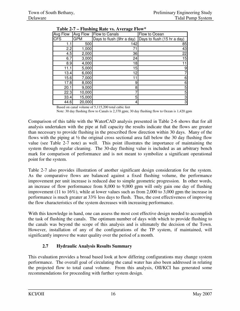
Town of South Bethany, Preliminary Engineering Study Delaware Tidal Pump System
KCI/OII 16 May 2007
Table 2-7 – Flushing Rate vs. Average Flow* Avg Flow Avg Flow Flow to Canals Flow to Ocean
CFS GPM Days to flush (9hr a day) Days to flush (15 hr a day)
1.1 500 142 85
2.2 1,000 71 43
4.5 2,000 36 22
6.7 3,000 24 15
8.9 4,000 18 11
11.1 5,000 15 9
13.4 6,000 12 7
15.6 7,000 11 6
17.8 8,000 9 6
20.1 9,000 8 5
22.3 10,000 7 5
33.4 15,000 5 3
44.6 20,000 4 3 Based on canal volume of 5,115,200 total cubic feet Note: 30 day flushing flow to Canals is 2,370 gpm; 30 day flushing flow to Ocean is 1,420 gpm
Comparison of this table with the WaterCAD analysis presented in Table 2-6 shows that for all analysis undertaken with the pipe at full capacity the results indicate that the flows are greater than necessary to provide flushing in the prescribed flow direction within 30 days. Many of the flows with the piping at ½ the original cross sectional area fall below the 30 day flushing flow value (see Table 2-7 note) as well. This point illustrates the importance of maintaining the system through regular cleaning. The 30-day flushing value is included as an arbitrary bench mark for comparison of performance and is not meant to symbolize a significant operational point for the system. Table 2-7 also provides illustration of another significant design consideration for the system. As the comparative flows are balanced against a fixed flushing volume, the performance improvement per unit increase is reduced due to simple geometric progression. In other words, an increase of flow performance from 8,000 to 9,000 gpm will only gain one day of flushing improvement (11 to 16%), while at lower values such as from 2,000 to 3,000 gpm the increase in performance is much greater at 33% less days to flush. Thus, the cost effectiveness of improving the flow characteristics of the system decreases with increasing performance. With this knowledge in hand, one can assess the most cost effective design needed to accomplish the task of flushing the canals. The optimum number of days with which to provide flushing to the canals was beyond the scope of this analysis and is ultimately the decision of the Town. However, installation of any of the configurations of the TP system, if maintained, will significantly improve the water quality over the period of a month.
2.7 Hydraulic Analysis Results Summary
This evaluation provides a broad based look at how differing configurations may change system performance. The overall goal of circulating the canal water has also been addressed in relating the projected flow to total canal volume. From this analysis, OII/KCI has generated some recommendations for proceeding with further system design.
Town of South Bethany, Preliminary Engineering Study Delaware Tidal Pump System
KCI/OII 17 May 2007
The check valve in the system does not add a significant value to the intent of the project. Within the hydraulics of the system any flow permitted to enter or leave the canals will generally improve water quality. Checking the flow to the canals at the south pipe will thus limit some of the circulation potential in the system and reduce overall system effectiveness. In addition, any water entering the ocean will be very effectively dispersed so that re-entraining significant amounts of removed canal water through the system is very unlikely in nearly all wave/weather conditions. The analysis leads to the conclusion that a single I/O may be adequate to move sufficient quantities of water to circulate the canal water. Thus, the system may be constructed through a phasing plan. Initially the system could be constructed with only the north I/O piping as Phase I. Should operational experience show the south I/O is needed, it could then be constructed as Phase II of the system. By phasing the project, this could potentially eliminate an estimated $1.6 million in initial Phase construction costs. 3. ENVIRONMENTAL FACTORS
There are various environmental factors which may affect the TP system. These include but are not limited to ocean currents and waves, sedimentation of sand and other debris, corrosivity of sea water, depth of the piping, and fouling from marine organisms. Subsurface or geotechnical considerations would also impact final design of the system.
3.1 Location
South Bethany is located along the exposed Atlantic seaboard within the coastal plain physiographic region. This means the area is predominately underlain by sedimentary material, predominately sand and is exposed to Atlantic storms and associated near-shore sediment transport. Due to these conditions, the beach area is subject to potential immediate and massive land formation shift from storm generated wave action.
For the purposes of the project, it is important to identify the wave forces likely to act within the area from the beach head to approximately 1,600 offshore at a depth of about 30 feet.
Anecdotal inspection of storm records shows that a single “nor’easter” or hurricane can cause significant erosion at the beach and surf zones at South Bethany. The erosive wave forces would also be extremely detrimental to any piping system within the surf zone. The proposed 36-inch piping if surface deployed would be significantly affected in such conditions.
The outfall pipe located at Fenwick Island State Park was prescribed to be constructed 50 feet offshore in the prior study, and, as such, the outlet will be in the surf zone. Because of the outfall location, this pipe will be exposed to extreme wave action and would have to be designed accordingly.
Town of South Bethany, Preliminary Engineering Study Delaware Tidal Pump System
KCI/OII 18 May 2007
3.2 Ocean Currents and Waves
Pipelines laid on the sea bottom are directly influenced by hydrodynamic forces resulting from currents. Typical currents caused by orbital movements of wave particles and near-coast currents can damage pipes especially during heavy seas or storms. Hydrodynamic forces cause erosion, transport and accretion of seabed material. Pipelines laid on the sea bottom may increase the current velocity and thus turbulences. A two-phase flow of sand and water under the pipeline may form. Scours develop, which depend on the following parameters:
• Vertical current velocity profile,
• Turbulence,
• Wave reflection,
• Bed material,
• Bed roughness.
If the pipeline is laid directly on the sea bottom, scouring can lead to a large free span of the pipeline between two supports.
If the pipeline is laid on concrete supports, the scouring may cause the supports and the pipeline to sink. The bending radius of the pipeline between two supports may be exceeded and pipeline may break.
The surf-zone is the most extreme environmental component of the design. According the USACE Coastal Engineering Manual, there is no standard for construction of piping in the surf zone. It is critical to have the pipe buried below the level of potential beach erosion to prevent the chance of the pipe becoming exposed. An exposed pipe in this area will be subject to intense wave and scour forces and will likely fail in the near term.
3.2.1 Currents
Currents over the continental shelf are important relative to rate and direction of transport of fluids and solids, and will affect inner shelf sediment transport. Currents are driven mainly by tides and winds, but temperature and salinity gradients, Coriolis effect, river discharges, and organized current systems (such as the Gulf Stream) can also be important. Currents can vary greatly between the surface and bottom. Currents at the Intake/Outfall structure created by tides will be minimal compared with other forces. The average tidal range in the South Bethany area is approximately four feet which is relatively small compared with many locations in the world. Surf zone currents are the driving force transporting sediments in both the longshore and cross-shore directions. As such, they are the key factor in beach erosion and accretion. Surf zone currents are driven by breaking waves and nearshore winds. Currents are very sensitive to wave direction. The magnitude of longshore transport can vary greatly over a time period of days, months, and even from year to year in response to natural variations in wind and wave climate. At many sites, even the dominant direction during a single year can deviate from the normal pattern. Thus, an adequate sample of years is necessary for stable design estimates.
Town of South Bethany, Preliminary Engineering Study Delaware Tidal Pump System
KCI/OII 19 May 2007
3.2.2 Project Area Wave Climate
Mean wave heights are fairly consistent along the entire U.S. Atlantic coast from 2.3 to 4.3 feet, with the project area of South Bethany exhibiting an average wave height of approximately 3.2 feet. Mean wave periods also exhibit a relatively high degree of consistency along the entire Atlantic coast, varying between 6.4 and 7.4 seconds. The highest probability direction of the waves along the exposed portion of the Delaware coast is from 124-degrees and appears to be primarily a function of coastal exposure.
According to the USACE Coastal Engineering Manual these results appear consistent with the average storm expected in the Atlantic coastal regions including the Delaware coast near South Bethany. In the northern portion of the Atlantic coast, the primary source of large waves are migratory extratropical cyclones. Between storm intervals in this region, waves come primarily from swells propagating from storms moving away from the coast. Due to this direction of storm movement, the swell from these storms is usually not very large (approximately 6.6 feet). The 90th percentile wave heights can be considered as representative of typical large wave conditions which are approximately 6.3 feet along the exposed portion of the Delaware coast. The associated period of these waves is approximately 7.9 seconds. Directions of the 90th-percentile wave reflect the general coastal orientation and are similar to the average wave direction at 126-degrees. The 5-year wave heights for the project area can be considered as representing typical large storms that might affect short-term projects such as the TP installation operations. Values of the 5-year wave height in the project area are approximately 5.7 feet. The associated wave periods are generally in the range of 11 to 13 seconds for this period storm. Extreme waves along the Atlantic coast, including the project area, are produced by both intense extratropical storms and tropical storms. Hurricanes, which are defined by sustained winds greater than 70 knots, can also produce extreme wave conditions along the coast. Particularly at the coast itself where storm surges of 10 feet or more can accompany waves. The return period for Hurricane strength conditions at the project site is greater than 30 years. The wave climate as described will not impact an I/O structure constructed 1,600 feet offshore at a depth of 30 feet, but would provide extreme stress to exposed piping or outfall structures within the surf zone.
3.3 Sediment Migration
3.3.1 Longshore Sediment Transport
The breaking waves and surf in the nearshore combine with various horizontal and vertical patterns of nearshore currents to transport beach sediments. Sometimes this transport results only in a local rearrangement of sand into bars and troughs, or into a series of embayments cut into the beach. At other times there are extensive longshore displacements of sediments, possibly moving hundreds of thousands of cubic yards of sand along the coast each year. The longshore
Town of South Bethany, Preliminary Engineering Study Delaware Tidal Pump System
KCI/OII 20 May 2007
sediment transport rate, is defined to occur primarily within the surf zone, directed parallel to the coast. This transport is among the most important nearshore processes that control beach morphology, and determines in large part whether shores erode, accrete, or remain stable.
Analysis completed by the Baltimore Section of the USACE indicates that the relative longshore sediment migration for the project area is approximately 150,000 cubic yards per year moving southward along the coast. The projected intake/outfall location 1,600 feet offshore is outside of the surf zone and would therefore be outside of the long-shore sediment transport zone. Thus, the proposed location of the system 1,600 feet offshore would not be significantly effected by this process.
3.3.2 Inner Shelf Transport
In coastal engineering, the seaward boundary of the surf zone is considered as the deepwater limit of significant wave and current effect. From the outer break point shoreward to the beach, waves and their associated currents are recognized as major sources of sediment resuspension and transport. Seaward of this point there is a region from roughly 7 to 10 feet deep to approximately 60 to 100 feet deep within which the importance of waves and currents on sediment transport processes is not well understood. This is the region, at a depth of 30-feet, in which the Intake/Outlet structure of the TP is to be deployed.
During severe coastal storms some material removed from the beach is carried offshore and deposited on the inner shelf in depths at which, under normal wave conditions, it is not resuspended. The fate of this material is governed by several variables which are not as of yet completely understood. To fully appreciate the complexity of this problem it is necessary to recognize that sediment transport has been extensively studied for decades and yet it is still not possible to predict transport rates with any degree of certainty. On the inner shelf, as on most of the active seabed, sediment transport is a nonlinear, turbulent, two-phase flow problem complicated by bed forms, bottom material characteristics, current variability, and by the superposition of waves. In addition, transport can be comprised of bed load as well as suspended load, the quantitative separation of which is of considerable complexity.(USACE CEM, 2006) Thus, it is not possible to quantify how much sediment may act on the TP Intake/Outfall structure once it is in place. However, most if not all potential sediment entrainment at the I/O structure would be expected to occur during storm events, as currents in the inner shelf zone will, in normal conditions, not be sufficient to move large quantities of sediment.
3.3.3 Canal Feeder Sediment Considerations
Sediment movement from the canals into the system will also be expected. Sediment entrainment into the TP system from the canals will be generated entirely by the flow entering the TP system as it moves from the canals to the ocean. This flow velocity will be in the range of 0 to 4 feet per second and will be generally insufficient to generate movement of residual sediment from the canal bottom into the TP system. However, in the case of already suspended sediment, the TP system will potentially draw this material into the piping during canal to ocean flow. The average suspended sediment in the canals was not analyzed as part of this cost study,
Town of South Bethany, Preliminary Engineering Study Delaware Tidal Pump System
KCI/OII 21 May 2007
but this will dictate how much possible material enters the TP system. A significant component to the suspended sediment in the canals will be generated by the Towns existing storm drain system, of which some discharge to the canal surface water. As stated, it was beyond this scope of this study to ascertain the overall effect of the stormwater discharge to the system.
It may be prudent to perform a total suspended solids (TSS) study as part of the design phase to quantity the possible sediment loading of the storm drain system to the TP. Should the impact be found to be significant, engineering controls, such as stormceptors, may be necessary to remove sediment from the portions of the storm drain system.
3.4 Storm Induced Flooding
Flooding in the South Bethany beach area associated with a storm surge is possible. As depicted on the topographic mapping of the town, the highest points are less than 20 feet above sea level. This high-point is generally located at the peak of the dune line, at which point the topography tails off toward the canal area to a height approximately 5 feet above mean sea level. Due to this configuration, the dune line acts as a sea-wall protecting the western portions of the town against peak waves or surges up to 10 to 15 feet above sea level.
In a storm surge scenario, when the storm surge allows the wave or sea-water flow past the dune line and the tidal pump system is in place, the following scenario may occur. The tidal system head line will as always attempt to mimic that of relative sea level such that there will be pressure inside the system for a water level 10-15 feet above sea level. Since the tidal pump system will be constructed as a closed system, flooding of Town would not occur from the piping system on land. However, the storms could cause significant ocean water surges into the canals resulting in potential flooding conditions near the canal feeder lines if the condition were to exist for an extended period of time. Thus, the proposed isolation valves should be closed during pending major storms to mitigate potential flooding during these storm events.
3.5 Geologic Setting
3.5.1 Area Geology
The project site is located in the Coastal Plain Physiographic Province. The Coastal Plain consists mainly of riverine, deltaic and marine sediments, which were deposited during successive periods of fluctuating sea level and moving shoreline. The formations dip slightly seaward and several are exposed at the surface in bands paralleling the coast. Many beds exist only as fragmental erosional remnants sandwiched between more continuous strata above and below. The soils in this province are typical of those laid down in a shallow sloping sea bottom; sands, silts, and clays with irregular deposits of shells. Some of the existing formations contain predominantly plastic clays interbedded with strata of sands and poorly consolidated limestone. Others contain predominantly sands and chalky or porous limestone with local lenticular deposits of highly plastic clays
Town of South Bethany, Preliminary Engineering Study Delaware Tidal Pump System
KCI/OII 22 May 2007
3.5.2 Site Geology
The site is mapped into Barrier Sand geological unit. It is a relatively young unit, and believed to have been formed in Holocene epoch, 0.1 million years ago. It consists of long, narrow bodies of sand paralleling the Atlantic coast. The soils are mostly light-colored, moderately to well-sorted sand, fine to very coarse-grained with scattered fine gravel. Broken shell fragments are abundant throughout this unit.
The geologic conditions of the specific construction area on the land side of the project can be partially ascertained through consultation of records from the construction of the existing utilities onsite. The area is predominately underlain with sandy soil with a high groundwater table.
Specific site conditions for this project should be identified through completion of a geotechnical drilling survey along the prescribed route. The specific information gained through the study will be critical in determining if any changes to design will be needed. The information will also be key in identifying the specific set up for installation methods. This information will include groundwater level and soil grain size distribution which will be important especially to trenchless installation, such as directional drilling, jack and bore or microtunneling.
3.6 Marine Fouling
Marine organism fouling presents one of the most significant potential impacts to the TP system. Any encrustation or buildup within the system will reduce the effectiveness of the flushing by restricting flow. The types of organisms which may enter and potentially effect system performance include barnacles, bivalve molluscs (mussels, oysters, clams), algae and other sessile organisms.
The marine creatures of most concern in all cases are the hard shelled barnacles and bivalves, which start life as free swimming larvae. The larval stage of theses creatures are very small, about the size of a pin head and as such are able to move through all but fine mesh filtering screens. The organisms will exist in this stage prior to identifying a spot were it will attach itself and begin growth into the adult stage organism. Once in place, the bi-valve will never move again. Identification of a spot to plant itself by each individual organism is based on several parameters. These include velocity of water flow, identification of a suitable substrate, and random chance. The most favorable substrate on which to attach is similar organisms, rocks or other generally rough stable surface. Greater flow conditions will generally inhibit attachment of these organisms. Some of the organisms however may settle on any submerged surface, including piping, through random motion. The creatures may grow for several years reaching sizes large enough to significantly restrict flow in pipes.
Algae and other similar marine plant growth will also present a fouling issue. This fouling is less significant than that of barnacles and bivalves, but will create a film on the pipe surface which will increase the surface roughness of the pipe, thus lowering system performance.
The system under nearly all conditions will be entirely inundated with seawater. Thus all surfaces of the pipe will be constantly exposed to potential growth. Another significant factor
Town of South Bethany, Preliminary Engineering Study Delaware Tidal Pump System
KCI/OII 23 May 2007
for consideration is during slack tide there will be a time when the water within the system is essentially stagnant. This period of essentially very little to no movement will last essentially for 30 minutes. This also means that due to the organisms settling tendencies, the larvae can essentially be drawn into any portion of the TP before a slack tide occurs, at which point, they may settle out and affix to a spot from which to grow.
These two points are critical because marine growth attaches more effectively in low flowing conditions and since the pipe is always fully inundated, the entire pipe surface area is exposed to growth. This essentially means there is no reserve capacity in the pipe which may be found in a situation where the pipe is designed to flow less than full.
Marine fouling in the TP system will be of more concern than in most offshore systems, since most intakes normally operate at flow rates which will restrict bi-valve growth. In the case of outfalls, the flow is always outward and relatively constant, both which help to reduce fouling. The TP meanwhile will be flowing at generally low velocities and will remain slack at two points during most 24-hour periods. Thus, periodic cleaning cycles will probably be the best measure to retain the original design integrity of the system.
3.7 Corrosion
Due to the highly corrosive nature of sea water any metallic substance used within the system will be exposed to corrosion potential. This can be counteracted by use of cathodic protection, however the protective anodes themselves will have to be replaced periodically. Thus, it is recommended to utilize non-corrosive material whenever possible in the TP design.
4. PERMITTITNG REQUIREMENTS
The TP system will need to meet a variety of permitting requirements including both environmental permitting and construction permitting. Due to the innovative nature of the design there exists a potential for delays in the process. To streamline the permitting it will be important to discuss the project as soon as possible with regulatory personnel and keep an open dialogue with them throughout the process of design. Whether the project is termed an experimental or a pilot project may also have a bearing on the amount of scrutiny or time required to meet all permit requirements.
From a permitting standpoint it may be better that this project not be represented as either ‘experimental’ or ‘pilot’ for the following reasons: An ‘experimental’ project would require extensive monitoring of pre-existing conditions, followed by a presentation of a hypothesis for what is proposed. After construction, post-construction conditions must be monitored and the success and/or failure of the ‘experiment’ must be evaluated. A ‘pilot’ project infers that it is the first of more projects of this type. Thus, unless the Town is planning to construct future Tidal Pump projects along the Delaware coast line, this term may not be appropriate. Final determination of this point should be made through consultation at regulatory agencies (see section 4.1).
Town of South Bethany, Preliminary Engineering Study Delaware Tidal Pump System
KCI/OII 24 May 2007
4.1 Environmental Permitting
A recommended first step in the permitting process for the subject project would be to present the proposed project components at the interagency meeting held at the Delaware Department of Natural Resources and Environmental Control (DNREC). The agency holds meetings on the first Thursday of each month. Notification will need to be made to Ms. Denise Rawding at (302) 739-9943 a minimum of two (2) weeks prior to the date to ensure that the project is included in the meeting agenda. The following agencies will be present at the meeting:
• U.S. Army, Corps of Engineers (ACOE)
• U.S. Fish and Wildlife Service (USFWS)
• U. S. Environmental Protection Agency (EPA)
• Delaware State Historic Preservation Office (SHPO)
• Delaware Natural Heritage Program
• Delaware Department of Natural Resources and Environmental Control (DNREC) o Division of Soil & Water Conservation Drainage & Stormwater Section o Coastal Management Program o Parks and Recreation
At the meeting, the agencies will be able to hear about the proposed project components and to voice their collective concerns as well as give guidance to various studies and additional information needed for submittal with the Permit Application of Subaqueous Lands, Wetlands, Marina and 401 Water Quality Certification Project and Joint Federal/State Application For The Alteration of Any Floodplain, Waterway, Tidal or Nontidal Wetland.
4.1.1 Permit Application
This project will most likely require an Individual Permit issued by the U.S. Army Corps of Engineers with review, comment and approval of all other agencies listed above. Permitting requirements will include but are not limited to the following elements:
• Submittal of (3) copies of an Application for Approval of Subaqueous lands,
wetlands, marina and water quality certification projects with appropriate fee to:
Department of Natural Resources and Environmental Control Division of Water Resources Wetlands and Subaqueous Lands Section 89 Kings Highway, Dover, DE 19901 (302) 739-9943
The permit application will include the following components:
• Scaled plans with cross sections that show design detail of proposed project.
• Supplemental Documentation including but not limited to:

Town of South Bethany, Preliminary Engineering Study Delaware Tidal Pump System
KCI/OII 25 May 2007
o Wetland delineation that includes surveyed limits of tidal/non-tidal Wetlands, Waters of the U.S., including water depths, mean high/mean low, etc.
o Forest resource analysis o Essential fish habitat (EFH), Submerged Aquatic Vegetation (e.g., eelgrass
Zostera marina) or Shellfish beds documentation form for the National Marine Fisheries
o Federally listed Rare, threatened and endangered specie (RTE) documentation from the U.S. Fish and Wildlife Service (USFWS)
o Natural Heritage site or National Estuarine Research Reserve documentation from Delaware Natural Heritage Program
o Eligibility for listing of national register historic places from Delaware State Historic Preservation Office (SHPO)
o Forest management plan for Department of Agriculture o Documentation for Federal Coastal Zone Consistency for DNREC Coastal
Management Program o Documentation of no adverse affect to Wild and Scenic River designated areas
or study status and receipt of concurrence (Submittal to the National Park Service)
• Application fee made payable to State of Delaware
• Adjacent property owners names and addresses
• Appendix C: Road Crossing
• Appendix D: Channel Modifications or Impoundment Structures
• Appendix E: Utility Crossings
• Appendix F: Intake or Outfall Structures
• Appendix I: Rip-Rap Sills and Revetments
• Appendix H: Fill
• Appendix J: Vegetative Stabilization
• Appendix M: Construction in State Wetlands o Environmental summary/evaluation of impact – avoidance & minimization
and alternatives analysis o Description of permanent impacts that can’t be avoided o Impact of proposed project on Value of tidal ebb and flow o Impact of proposed project on Habitat value o Impact of proposed project on Aesthetic Effect o Impact of proposed project on Supporting Facilities o Impact of proposed project on Neighboring Land Use o Impact of proposed project on Federal, State, Regional, County and Municipal
Comprehensive Plans o Impact of proposed project on Economic Impact shall include a short and long
term evaluation of:
• Appendix R: maintenance dredging or excavating Additional agency coordination needed in addition to submittal of the Joint Permit application and supplemental documentation package:
Town of South Bethany, Preliminary Engineering Study Delaware Tidal Pump System
KCI/OII 26 May 2007
• U.S. Coast Guard - coordinate project
• USFWS - submit request for Federally listed Rare, threatened and endangered specie (RTE) documentation
• SHPO - submit request for Eligibility for listing of national register historic places
• National Marine Fisheries – submit Essential fish habitat (EFH), Submerged Aquatic Vegetation (e.g., eelgrass Zostera marina) or Shellfish beds documentation form
• National Park Service – submit request for no adverse affect to Wild and Scenic River designated areas or study status
• Delaware Department of Transportation Highway Operations (DelDOT) – coordinate for maintenance of traffic issues
• Sussex Conservation District – coordinate for sediment and erosion control
• Various Utility Companies – coordinate potential impact/and/or relocation activities
4.1.2 Sediment and Erosion Control
The project will need to obtain Sediment and Erosion Control permits from DNREC/Sussex Conservation District for all construction activities. Sediment and erosion control may be phased according to tidal and/or non-tidal wetland or waters of the U.S. impacts and construction time of year restrictions for plant, animal or anadromous fish resources.
4.1.3 Stormwater Management
The project is expected to obtain a stormwater management waiver from DNREC. NPDES coordination, potentially due to the low water quality of existing canals may also be required. Depending on responses from individual agencies, additional permits/waivers may be required related to stream closure dates, plant or animal species preservation or avoidance requirements, mitigation design/permit requirements, or stormwater and/or sediment control permit or waiver requirements.
4.2 Construction Permitting
A construction permit, completely separate from the environmental permits, will also have to be obtained from DNREC. The application for this permit can be drafted and submitted approximately half-way through the design stage and the permit can be obtained well before the possible start state. The following construction related permit coordination must take place:
• An ACOE Pre-construction notification
• Coastal Construction Permit or Coastal Construction Letter of Approval from DNREC
• Coordination with DelDOT for highway construction/drainage/maintenance of traffic issues
Town of South Bethany, Preliminary Engineering Study Delaware Tidal Pump System
KCI/OII 27 May 2007
4.3 Easements and Right of Ways
Easement and Right of Way impacts will be minimal as all portions of the alignment have been located within existing roadways and their associated existing right of ways. The exception to this exists as the north I/O proceeds under North Sixth Street to the beach. It is preliminary planned to proceed under this area utilizing HDD, thus impact to the property will be minimal, but will require taking of an easement from one property.
5. PIPING MATERIALS Piping materials were evaluated to identify the most suitable for the inlet/outlet, main and outlet legs, and canal branches; and rationale for selection of the recommended materials was applied. Factors considered during review of these materials included cost, maintenance, corrosion, constructability issues, marine fouling, availability and survivability.
5.1 Pipe Materials Considered
Numerous pipe materials were evaluated to determine the overall suitability for the intended operation and varying site conditions. The pipe materials considered included:
• Coated and/or Lined Carbon Steel (CS)
• Ductile Iron (DI)
• High Density Polyethylene (HDPE)
• Fiberglass Reinforced Plastic (FRP)
• Polyvinyl Chloride (PVC)
• Reinforced Concrete (RC)
• Centrifugally Cast Fiberglass Reinforced Polymer Mortar Pipe (CCFRPM)
• Copper-Nickel (CN)
• Copper Sleeving
The applicability of the material to the intake and outfall system piping depends upon the required system design life and water chemistry such as chloride and oxygen content and construction methods. Plastic and resin based piping systems (HDPE, FRP and PVC), while somewhat more expensive than the ferrous and concrete systems, provide superior corrosion resistance and flow characteristics. Ferrous and concrete systems offer good armoring characteristics and, in some cases, less cost.
The piping material for the feeder and trunk lines, while land based, would constantly be flowing full of canal or ocean water due to the system configuration. Consequently, these pipes would face the same threat of marine fouling and potential corrosion as the ocean outfall/intake piping. Thus, use of a similar material throughout the system is practical from an operation standpoint.
Depending on the pipe material various connection methods may be used which may include fused pipe, bell & spigot or straight coupling joints. The need for fabrication of the various fittings including reducers, tees, etc. was considered. For final design it will be important to
Town of South Bethany, Preliminary Engineering Study Delaware Tidal Pump System
KCI/OII 28 May 2007
specify readily available materials and avoid specially fabricated fittings to provide the most cost effective design. The consideration of armoring or ballasting of the pipe will depend upon the material considered. For example, metallic and concrete piping, as stated above, will have natural armoring characteristics and their high density will generally mean ballasting of these materials would not be needed in conditions similar to the TP project area. In contrast, lighter pipe material such as the plastics, may need armor to protect against impact as well as ballast to maintain submergence. In the case of HDPE, it is recommended to provide ballast even if the pipe is trenched into place, due to its natural buoyancy in water. The general characteristics of each material type as they may apply to the project are as follows:
Coated and/or Lined Carbon Steel (CS):
Most subsea pipelines are steel material, almost exclusively so for oil and gas submarine pipelines. Flowlines and transmission pipelines for the oil and gas industry are constructed from carbon steel alloyed with manganese and fabricated to conform with the American Petroleum Institute 5L specification. Steel is a tough material that can survive impacts and fails in a ductile progressive manner whereas non-tough brittle materials do not. Steel pipes have been used for a number of outfall pipelines as well, but are susceptible to corrosion and need to be internally coated with mortar protection. Steel pipeline lengths are typically butt welded end to end to form continuous pipeline strings. The strings are then butt welded together to make up the complete pipe length. The strength of steel means relatively high stresses can be tolerated during installation and operation. However, the mortar lining required for effluent pipelines severely limits the allowable bending radius, complicating the installation procedures. Similarly, the inherent weight of the steel combined with that of the necessary coatings makes handling during construction a significant factor.
Ductile Iron (DI):
DI is a cost effective alternative to CS systems in diameters through 12 inches. Large bore DI is more expensive than CS. Though the pipes are supplied with a factory coating to inhibit corrosion; this coating has been know to become damaged during installation making the pipe vulnerable to corrosion. The pipes can be installed with a cathodic protection systems, however these systems add cost to the pipeline resulting in higher costs than other pipe material. Unit cost of the DIP is currently approximately $54/LF for 12-inch pipe.
High Density Polyethylene (HDPE):
Recent improvements in manufacturing and quality programs show that HDPE is a very viable material in intake/outfall piping systems ranging in size from 6 to 63 inch outside diameter. HDPE is an extremely tough product, is easily fabricated, has excellent flow characteristics, offers good insulation qualities and is inert to the surrounding water
Town of South Bethany, Preliminary Engineering Study Delaware Tidal Pump System
KCI/OII 29 May 2007
system. HDPE is lighter than water (96% the density of fresh water, and about 94% of sea water) and, therefore, requires substantial anchoring ballast to sink and hold the pipe in place. Additionally, HDPE is inert to biological degradation. It is indigestible, has no food value and will not support (as a food source) the growth of organisms of any kind. The smooth surface of polyethylene pipe, particularly on the inside, discourages the adherence of algae growths. Under essentially static conditions of flow, algae may deposit on the inside walls, but they readily flush off at low flow velocities. Where marine growth has become established, their size of growth and thickness of incrustation have been reported as significantly smaller than those associated with other materials. Butt fusion is a typical jointing method for HDPE pipe. By this method, pipe and welded joint are homogeneous, and the strength of the welded joint is at least equal to that of the pipe. This type of welded joint is also leak proof. Welding can be completed above ground and prefabricated strings of HDPE can be jointed underwater with flanges.
Currently, most deep water pipeline designs use polyethylene as the pipe material. Its main advantages are its buoyancy, flexibility for installation, high strength, resilience to shock, corrosion resistance, high fatigue strength, and almost unlimited life expectancy underwater.
Pipe wall thickness for TP project use will be based upon the chosen installation method and may range from and SDR rating of 9 (for bottom pull) to approximately 21 (for float and sink). SDR rating refers to the ratio of pipe diameter to pipe wall thickness, thus SDR of 9 indicates a wall thickness of which is 1/9 of the outside diameter of the pipe, or 2.3 times greater wall thickness than SDR 21 wall thickness.
Marine installation of HDPE will require ballasting unless installed via HDD. Ballasting is normally accomplished utilizing specialized concrete anchors which mount onto the pipe during the installation process. Ballast weight totals very based on condition but may range from 25% of total pipe displacement at depths greater than 40 feet to up to 70% at near shore locations. The range of the weight for the TP project would total approximately 40% of the displacement in a trenched installation. Ballast may increase pipe unit cost by from 25% to 50%.
Unit cost of HDPE piping is currently approximately $12/LF for 12-inch pipe and $55/LF for 36-inch pipe.
Fiberglass Reinforced Plastic (FRP):
FRP is commercially available in sizes in excess of eight feet in diameter. It is durable, offers good flow characteristics and is corrosion resistant. FRP is easy to handle and is patchable if accessible. However, FRP is subject to impact damage. FRP is the one of the most widely used plastic pipes in the industry. Most applications are for onshore use mainly for water and effluent pipelines. FRP pipe can be classified
Town of South Bethany, Preliminary Engineering Study Delaware Tidal Pump System
KCI/OII 30 May 2007
according to the form of construction of the pipe wall laminate, which in turn is largely determined by the manufacturing technique employed. There are two main techniques: centrifugal casting and filament winding. The behavior of the FRP composite is determined by the chemical resistance of the resin. There are various limitations to FRP pipe:
• Pressure limitations – The pressure is restricted to between 90 and 350 psi, depending on the manufacturer;
• Temperature exerts a significant effect on the behavious of the pipe. Strength decreases with higher temperature, also expansion of FRP pipes is very high.
• FRP pipes need support at more frequent intervals than steel pipe.
• FRP pipes cannot be concrete coated for stability. The main advantage of FRP is that it does not require an anti-corrosion coating. Another advantage is its lightweight. The installation of FRP pipe can be very difficult. In addition, the cost of FRP is high as compared to either CS or HDPE pipe.
Polyvinyl Chloride (PVC):
PVC is available in sizes required by the project and could be an economic material for short intake systems with very low piping pressures. Standard PVC pipe would not be strong enough for utilization with the offshore components of the TP system. However, the C-900 and C-905 PVC pressure pipe types, which employ greater wall thickness and which are used in water system design, may be applicable for the TP system. Unit cost of the C-900 is currently approximately $26/LF for 12-inch pipe and $135/LF for 36-inch pipe.
Reinforced Concrete (RC):
RC is available for pipe diameters through 100 inches. Various joining techniques are available. RC is heavy and bulky; but, it could be an economic material for short intake and outfall systems. However, if the outer concrete of the pipe is compromised, the reinforcing would be exposed to corrosion due to the aggressive nature of sea water towards steel. Concrete pipes whether prestressed or reinforced concrete are commonly used for sewer pipes and for outfalls but generally only in relatively calm seastate environments. The exception is for big diameter pipes, 78-inch and greater. However, the use of concrete pipes generally limits the installation options to dig and lay. The main reason is the connection between pipe elements is typically capable of taking the high tension loads imposed by the bottom tow method of installation, although concrete pipe lengths have in the past been post tensioned to make a continuous length fully capable of taking tension. The tension loads would in any event be high requiring a high capacity linear pull winch. Commonly bell and spigot type connections with rubber O rings are used. This type of connection imposes strict limits on the pipe alignment required to achieve connection and are susceptible to leaking if tension is either applied across the joint, or induced by

Town of South Bethany, Preliminary Engineering Study Delaware Tidal Pump System
KCI/OII 31 May 2007
uneven settlement of the pipes. Furthermore, these types of pipe joints are not intended to withstand the extreme forces during a pull installation. Unit cost for RCP is currently approximately $24/LF for 12-inch pipe and $100/LF for 36-inch pipe.
Centrifugally Cast Fiberglass Reinforced Polymer Mortar Pipe (CCFRPM):
This pipe material is available in diameters 18 to 110 inches. Installation methods include sliplining, direct bury, microtunneling and jacking. Corrosion resistant, superior hydraulic characteristics and leak-free couplings provide for a long maintenance free life. This type of pipe is commonly known by the manufacturer’s name Hobas.
Copper-Nickel Piping (CN):
This pipe material is extensively used in off-shore structures and vessels because of its natural resistance to marine fouling and low corrosivity compared with other metals in seawater. However, compared with other materials, such as plastics which do not experience galvanic corrosion, CN is susceptible to corrosion and would have a limited lifetime of 20 to 30 years in applications similar to the tidal pump design. The high cost of CN is prohibitive upon comparison with other materials. Unit cost for CN is currently approximately $900/LF for 12-inch pipe and $2,500/LF for 36-inch pipe which would require specially ordered fabrication.
Copper Sleeving:
Copper sleeving has been used to provide marine fouling protection for pipelines of other material. Generally, use of the copper sleeve inhibits adherence of marine organisms within the sleeved area. Within the TP system, although the entire system would be susceptible to growth, the entrance zones would likely experience a greater level of fouling then would the central areas. The copper sleeving could thus be installed into a portion of the TP, ideally near the entrance zones. However, the copper sleeving is susceptible to corrosion over time. The cost of copper piping as a liner is significant. A 12-inch diameter minimal thickness copper pipe currently has a unit cost of $510 per linear foot. A 36-inch diameter copper piping is not currently manufactured and would require special order with a likely high unit cost of a least $2,500 per linear foot. Due to the high excessive cost and unavailability of the pipe material, CS was eliminated from further consideration.
5.2 Material Comparison
To provide an overview of each pipe material type, each was rated on a 1 to 3 scale based upon the variety of criterion being considered. A “1” on the scale indicates the pipe ranks above average on this criterion, a “2” indicates an average rating, while a “3” is below average. A pair-
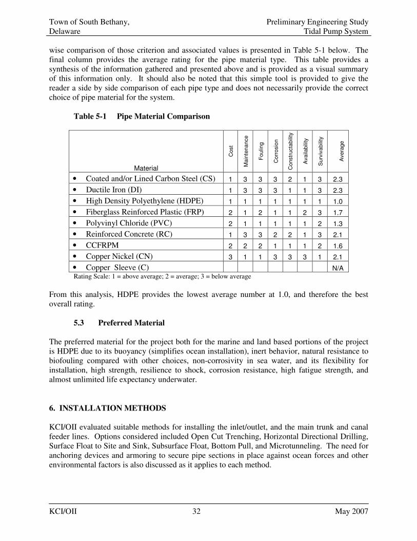
Town of South Bethany, Preliminary Engineering Study Delaware Tidal Pump System
KCI/OII 32 May 2007
wise comparison of those criterion and associated values is presented in Table 5-1 below. The final column provides the average rating for the pipe material type. This table provides a synthesis of the information gathered and presented above and is provided as a visual summary of this information only. It should also be noted that this simple tool is provided to give the reader a side by side comparison of each pipe type and does not necessarily provide the correct choice of pipe material for the system. Table 5-1 Pipe Material Comparison
Material
Cost
Main
tenance
Foulin
g
Corr
osio
n
Constr
ucta
bili
ty
Availa
bili
ty
Surv
ivabili
ty
Avera
ge
• Coated and/or Lined Carbon Steel (CS) 1 3 3 3 2 1 3 2.3
• Ductile Iron (DI) 1 3 3 3 1 1 3 2.3
• High Density Polyethylene (HDPE) 1 1 1 1 1 1 1 1.0
• Fiberglass Reinforced Plastic (FRP) 2 1 2 1 1 2 3 1.7
• Polyvinyl Chloride (PVC) 2 1 1 1 1 1 2 1.3
• Reinforced Concrete (RC) 1 3 3 2 2 1 3 2.1
• CCFRPM 2 2 2 1 1 1 2 1.6
• Copper Nickel (CN) 3 1 1 3 3 3 1 2.1
• Copper Sleeve (C) N/A Rating Scale: 1 = above average; 2 = average; 3 = below average
From this analysis, HDPE provides the lowest average number at 1.0, and therefore the best overall rating. 5.3 Preferred Material
The preferred material for the project both for the marine and land based portions of the project is HDPE due to its buoyancy (simplifies ocean installation), inert behavior, natural resistance to biofouling compared with other choices, non-corrosivity in sea water, and its flexibility for installation, high strength, resilience to shock, corrosion resistance, high fatigue strength, and almost unlimited life expectancy underwater.
6. INSTALLATION METHODS
KCI/OII evaluated suitable methods for installing the inlet/outlet, and the main trunk and canal feeder lines. Options considered included Open Cut Trenching, Horizontal Directional Drilling, Surface Float to Site and Sink, Subsurface Float, Bottom Pull, and Microtunneling. The need for anchoring devices and armoring to secure pipe sections in place against ocean forces and other environmental factors is also discussed as it applies to each method.
Town of South Bethany, Preliminary Engineering Study Delaware Tidal Pump System
KCI/OII 33 May 2007
6.1 Intake/Outfall and Outfall Line Installation Methods
The offshore marine piping can be installed using several techniques including tunneling, trenching and surface routing. Microtunneling machines can directionally drill tunnels up to 6 feet in diameter. Other tunneling techniques have been successfully used to bore significantly larger tunnels under large bodies of water. Tunneling generally is the most expensive offshore pipe installation technique, although the least obtrusive.
Marine piping can also be laid in a trench in the ocean or lake bottom. Conventional marine excavation or dredging is possible to depths approaching 50 feet. Dredging is possible in deeper water, although the costs become prohibitive. The trenched piping can be armored with rock or material from the dredging activity.
Various installation methods that may be applicable for the TP system are detailed below.
6.1.1 Open Cut Trenching
Open Cut Trenching is the most common and least expensive method of pipe installation for land based construction. This method would likely be employed on most of the shore based construction for the project excluding the crossing under Route 1. Utilization of a trench box and dewatering pumps is used in conjunction with excavation equipment to open up a trench for the desired piping material. Open-cut installation can also be used at sea (also known as dig and lay method) and in shallow areas and may involve the use of an excavator to cut the trench. Other means of installation involve the use of specially designed plows which created a furrow for the piping system, behind which the pipe is dragged and put into place. The barrow material from the plowing is then placed over the pipe to bury the system. Dredging heads, both mechanical and hydraulic, may also be used to cut the trench. Once the pipe is buried after an open cut installation, or other means, armoring of the covering material is sometimes undertaken as protection against scour. This armoring can be provided through the use of armor stone, armor mats, geotextiles or a combination of these materials. For the TP system, it is recommended that ballasting be utilized in place of armoring. Once ballasted, should the pipe becomes exposed via scour, the concrete ballast material would need to be designed to hold the pipe in place. Application of open-cut methods for this project is not recommended within the surf-zone of the inlet/outfall design as depth of bury would have to be significant to protect the pipe against possible exposure through scour and wave forces. This method, however, is viable for the outfall pipe installation beyond the surf zone and along Route 1 .
Town of South Bethany, Preliminary Engineering Study Delaware Tidal Pump System
KCI/OII 34 May 2007
6.1.2 Microtunneling
Microtunneling involves the installation of pipe through use of a remote-controlled tunneling machine, behind which the pipe is pulled or jacked into place. This procedure is typically used in the utility industry for relatively short tunnels, such as under roadways. Microtunneling provides a means of accurately controlling the grade at which a pipe is installed in a tunneling scenario. The process is also used in offshore situations for installation of larger diameter piping and in situations where precision grade alignment is necessary. In general, microtunneling is relatively more costly than horizontal directional drilling.
In order to be feasible on land versus other methods, a prospective alignment must have adequate jacking and receiving pit locations available. In addition, prospective jacking and receiving pit sites must be spaced at distances that are compatible with microtunneling techniques. The maximum distance that pipe can be jacked from a pit without the use of intermediate jacking stations is 750 ft with a typical range of 400 to 500 ft. The maximum distance is dependent on variables such as type of pipe, pipe size, structural capacity of the pipe, thrust capacity of the main jacks, soil conditions, and effectiveness of the bentonite lubrication system.
Due to the length consideration associated with installations using microtunneling, this method would be most applicable for the pipeline borings under Route 1. It would not be the most feasible application for installation of the outfall or intake/outfall lines because of the length limitation for typical jacking and the precision achieved with the method. That is, the offshore elements of the project do not need to be constructed with a precise slope to obtain optimum performance. Bore and jack tunneling is also a viable alternative for use at the Route 1 crossings. This method is identical to microtunneling, without the use of a controllable boring machine, and can be employed effectively for short road crossings at a significantly lower cost.
6.1.3 Horizontal Directional Drill
Horizontal directional drilling (HDD) is another commonly used trenchless pipe installation method. The principle is to set up an inclined drilling rig and to drill a hole under the beach and the surf zone, emerging on the seabed near the intake/outfall structure. HDD along with microtunneling have the least environmental impact of any installation technique. They are also the most expensive but avoid any exposure of the pipeline to wave action in shallow water where the wave induced hydrodynamic forces are at a maximum. While difficult in sand though possible, HDD performs best in weak sedimentary rock. Starting from onshore behind the sand dunes a pilot hole would be drilled, down under the dunes, under and across the beach emerging on the seabed at the intake site. The drill bit can be steered to within 3 to 6 feet of a defined target point. The directional control is achieved by a small bend in the drill string just behind the cutting bit to provide a bias in one direction. The drilling string is not rotated during the kick off or change in direction except to orient the bend. Once the drilling is established on the new direction, rotation of the whole drill string is resumed. Drilling mud is pumped through the drill string pipe to drive the down hole cutting tool, after which it
Town of South Bethany, Preliminary Engineering Study Delaware Tidal Pump System
KCI/OII 35 May 2007
passes back up the borehole, carrying drill cuttings and stabilizing the hole, before exiting back on the surface. The drill path is monitored by an electronic package incorporated in the drilling string near the cutting head. This unit monitors the position and inclination of the drill string relative to the earth's magnetic field. The data are transmitted back to the surface for reduction and evaluation. On completion of the pilot hole, the hole must be enlarged to a larger diameter to accommodate the pipe to be installed. The borehole is drilled to a larger diameter than the pipe it has to accommodate in a process known as prereaming. In a conventional pipe installation the pipe is pulled in from offshore once the drilled hole has been enlarged. A reamer is attached to the pull head on the end of the pipeline via a swivel, which prevents any translation of the reamer's rotation into the pipeline string, and the assembly connected to and pulled by the drill string from shore. For the TP project, a contractor with experience in drilling through sand would be preferred to anticipate the difficulties associated with HDD through the medium. Another consideration in utilizing HDD is the significant mobilization cost associated with the procedure. In addition, the drilling mud used will have to be sufficiently controlled as not to be flushed to the ocean once the penetration is made in the seabed. This would be achieved by the contractor employing safeguard strategies which will add some cost to the installation operations. Control of the drilling mud at the seabed penetration site will likely be a consideration in permitting of the project.
A recent KCI project involved the installation of a treatment plant outfall pipe, 1,100 LF off-shore into the navigable waters of the Potomac River, to a minimum submerged depth of 36-feet below mean low tide, to reduce ecological disturbance to adjacent oyster bars. Based on site conditions, KCI designed the install by means of directional drilling. The design approach was to establish a drilling pit on land and pullback the outfall pipe from the water. The material selected for the outfall was fused HDPE. The outfall pipe was capped on both ends and floated in the water. The pipe was then pulled back landward.
6.1.4 Surface Float and Sink
The least expensive configuration is laying the piping on the bottom. The surface float method for achieving this involves moving the piping on the surface and sinking it into position. Float and sink is a viable option for the TP pipeline. The section to be sunk can be fabricated in lengths onshore at a construction site and floated out to the location. The pipeline can float air-filled, with the concrete weights attached to the pipeline for on bottom stability. Once on location, the pipeline is flooded from one end and pulled down to connect to the seaward end of the preceding pipeline string. The connection will be made up by divers. The construction plant requirements for this method of installation are light, being principally work boat units, but considerable diver intervention is required. Burial of the pipeline can either be carried out after the pipeline is in place on the seabed using a jetting machine or the pipeline can be placed directly into a prepared trench. Either way the
Town of South Bethany, Preliminary Engineering Study Delaware Tidal Pump System
KCI/OII 36 May 2007
pipeline will need to be stable on the seabed until the trenching or backfilling work is undertaken. The sides of a prepared trench will have a low slope and the shallow trench will not offer much shelter to the pipe. Possible difficulties with this method may occur if heavy weather/surf conditions are encountered during the process. Careful considerations must also be made during the sinking process to make sure the pipe is placed without damage and in the correct position.
6.1.5 Subsurface Floating Line
A subsurface floating line deployment actually suspends the pipeline within the water column, freely floating above the bottom. In this method the pipe, which must be buoyant relative to water, is anchored at several points with large gravity anchors and cables. The concrete anchor size, based upon design force loading, may reach 20 to 40 tons each. The appearance of the system is that of an inverted catenary. This method has been used primarily with HDPE because of its buoyancy, strength, and flexibility. This method is utilized for areas were extensive rock is present on the bottom which would feasibly prohibit subsurface installation. The area of deployment must also be free of potential shipping concerns such as vessel anchor or trawler interference with the suspended pipe. Additionally, the method is also used for deepwater intake applications, so that suspended depth is below the zone of wave force interference. Applicability of this method for the TP system would be limited by the potential interference it would cause to vessel operation in the area. In addition, this method could not be utilized within the surf zone. The relatively shallow depth of the project and thus the potential wave force interaction would also likely prohibit floating installation of the pipeline.
6.1.6 Bottom Pull
Installation of the pipe on the bottom could also be undertaken by pulling the system from landward to the intake/outfall site. The bottom tow method, where the pipe is fabricated on and towed off the beach at the project location, is one of the most widely used method for the installation of ocean outfalls. It is less sensitive to seastate conditions than surface or off bottom flotation methods but still requires a relatively mild seastate window for the launching of the pipe, and an outfall pipeline that is robust and sufficiently weighted to remain stable following launch and flooding. The technique is best suited to the installation of steel pipelines given the ability of a continuous steel pipeline to accept high tension stresses. It can be used for HDPE pipe but the tension stresses must be carefully controlled or taken by a backbone element to which the HDPE pipes are attached, given the propensity for HDPE material to stretch. The bottom tow pipeline is generally fabricated as a number or series of pipe strings on a launchway onshore, the length of each pipe string being set by the length of launchway available. The first length to be launched, is assembled on the launchway and the succeeding pipe strings
Town of South Bethany, Preliminary Engineering Study Delaware Tidal Pump System
KCI/OII 37 May 2007
stored parallel and to one side of the launchway axis. A railway system transverse to the launchway axis is typically used to transfer the pipe strings onto the launchway axis. The launch of the pipeline proceeds in a series of steps. At the end of each step the succeeding pipe string is transferred across to the launchway axis and connected to the end of the preceding string. For steel pipelines the connection is made via a butt weld. The connection process can take up to 12 hours and longer for a large diameter pipeline. For the bottom tow option a single continuous length is the optimum, which imposes constraints on the launch sites, the entire pipe length has to be accommodated on the launchway. The pipeline is pulled by a winch from offshore. Typically the winch is a hydraulically powered linear winch mounted on a construction vessel moored out beyond the final diffuser position. The winch could also be mounted on a skid on the seabed with the skid connected to the end of the diffuser and the winch used to pull its way along the pull wire laid out in advance on the seabed. The hydraulic power to drive the winch in this case is supplied from a small surface support vessel carrying the hydraulic power pack moored close to the pulling head. This arrangement eliminates the weather sensitivity of the barge and avoids problems with excessive friction loads on the tow cable. If the pull is interrupted by bad weather the pipeline can be flooded to keep it stable. The risk with this approach on a sand seabed is that the whole pipeline and the towing head can become buried in the sand. Recovery after a storm event then becomes a major problem and for that reason can only be considered for a pipeline that can be bottom towed to location within the constraints of the expected weather window. A construction barge is necessary, whether the linear winch is mounted on a subsea skid or on the deck of the barge, to provide lifting capacity offshore.
6.1.7 Beach Crossing – Sheet Piling
Unless a trenchless method of installation is selected, the transition from the sea to the shore, the beach or shore crossing, will have to be made inside a sheet piled trench through the surf zone. The installation of the sheet piling and the excavation of the trench is carried out by a plant operating from a trestle structure alongside the line of the pipe. The depth of excavation is set to have the top of the pipeline well below the lowest known seabed profile. The trestle and the sheet piling have to be particularly robust as they may have to remain in place for an extended period, awaiting a suitable weather window for the installation of the pipeline. Upon installation of the pipe, the sheeting is removed.
6.1.8 Beach Crossing - Horizontal Directional Drilling
The alternative to the use of the conventional sheet piled trench for the shore crossing is the Horizontal Directional Drilling technique as defined above. Use of the HDD method would preclude the need for special shore crossing techniques such as sheet piled trenching.
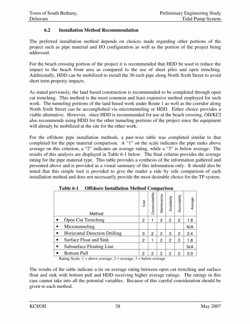
Town of South Bethany, Preliminary Engineering Study Delaware Tidal Pump System
KCI/OII 38 May 2007
6.2 Installation Method Recommendation
The preferred installation method depends on choices made regarding other portions of the project such as pipe material and I/O configuration as well as the portion of the project being addressed. For the beach crossing portion of the project it is recommended that HDD be used to reduce the impact to the beach front area as compared to the use of sheet piles and open trenching. Additionally, HDD can be mobilized to install the 36-inch pipe along North Sixth Street to avoid short term property impacts. As stated previously, the land based construction is recommended to be completed through open cut trenching. This method is the most common and least expensive method employed for such work. The tunneling portions of the land based work under Route 1 as well as the corridor along North Sixth Street can be accomplished via microtunneling or HDD. Either choice provides a viable alternative. However, since HDD is recommended for use at the beach crossing, OII/KCI also recommends using HDD for the other tunneling portions of the project since the equipment will already be mobilized at the site for the other work. For the offshore pipe installation methods, a pair-wise table was completed similar to that completed for the pipe material comparison. A “1” on the scale indicates the pipe ranks above average on this criterion, a “2” indicates an average rating, while a “3” is below average. The results of this analysis are displayed in Table 6-1 below. The final column provides the average rating for the pipe material type. This table provides a synthesis of the information gathered and presented above and is provided as a visual summary of this information only. It should also be noted that this simple tool is provided to give the reader a side by side comparison of each installation method and does not necessarily provide the most desirable choice for the TP system. Table 6-1 Offshore Installation Method Comparison
Method
Cost
Constr
ucta
bili
ty
Main
tenance
Availa
bili
ty
Surv
ivabili
ty
Avera
ge
• Open Cut Trenching 2 1 2 2 2 1.8
• Microtunneling N/A
• Horizontal Direction Drilling 3 2 2 3 2 2.4
• Surface Float and Sink 2 1 2 2 2 1.8
• Subsurface Floating Line N/A
• Bottom Pull 2 2 2 2 2 2.0 Rating Scale: 1 = above average; 2 = average; 3 = below average
The results of the table indicate a tie on average rating between open cut trenching and surface float and sink with bottom pull and HDD receiving higher average ratings. The ratings in this case cannot take into all the potential variables. Because of this careful consideration should be given to each method.
Town of South Bethany, Preliminary Engineering Study Delaware Tidal Pump System
KCI/OII 39 May 2007
HDD is still a viable possibility since the equipment will likely already be onsite for use in other portions of the work. In addition, since HDD is recommended for use to cross the beach area, a contractor competent in the use of the method in marine environments will also be involved with the project. The negative side of HDD can be cost and availability of contractors. Regional HDD contractors may not be able to accomplish the installation, thus national level firms will likely be necessary to complete the installation using HDD. In addition, drilling in sand conditions can be difficult for all but the most experienced operators. The drilling mud needed for HDD is also a consideration in environmental permitting for the work. Considering these elements of installation, if a competent HDD drilling contractor receives the contract, HDD is considered to be viable as a means to complete the offshore installation. As noted above the bottom pull method is not recommended for use with HDPE as the forces involved may cause the pipe to stretch. There are means to alleviate the stress, but in lieu of the other methods available, bottom pull is not considered the best choice available.
The open cut trench and surface float and sink are similar methods in which the pipe is floated into position and sunk. The open trench method requires a trench be dredged prior to the sinking, while the float and sink method employs jetting heads to sink the pipe into the seabed once it is resting on the bottom. Both methods will require ballasting of the pipe to provide a successful installation. For cost estimation purposes the concrete ballast cost is based upon 40% of the submerged pipe displacement for both of these methods. The variation in applications is based upon the prior dredging needed for open trenching. This trench can be susceptible to filling in prior to the pipe being installed especially in heavy sea conditions and with the sandy conditions likely prevalent along the entire alignment, thus requiring additional dredging to keep the trench open. For such operations contractors sometimes budget for double dredging of the trench for just this reason. Because of this the open trench method may also be slightly more costly than float and sink. However this will be affected significantly by the specific contractor and their experience utilizing either method. In lieu of the information gathered the most cost effective means to complete the offshore portion of the work appears to be the float and sink method. However due to the potential variability of contractor skills and potential pricing based upon their experience, OII/KCI recommends allowing contractor selection of a method of installation for the offshore portion of the system. As several installation methods are viable for this project, this will likely provide a greater number of bidders who, based upon their expertise will choose a method in which they are proficient and competitive.
6.3 Trunk and Feeder Line Installation
As identified above most shore based piping will almost certainly be installed using primarily open trench methods. The option exists for tunneling the connection which crosses beneath Route 1. In addition, the section of the piping which runs along North Sixth Street may be installed via HDD to avoid surface impact to the roadway and inconvenience to property owners.
Town of South Bethany, Preliminary Engineering Study Delaware Tidal Pump System
KCI/OII 40 May 2007
6.4 Intake and Outfall Considerations
The design of the intake and outfall piping is based upon the need to draw in and expel water while preventing excessive marine life and debris from entering into the piping. The primary factors used to design the intake piping are similar to those imposed on any water piping system. A trade off between piping system capital cost and pressure drop is used as a means to determine the proper line sizing. Pipe wall thickness of the intake system is related to the pipe material, pipe diameter, design pressure, temperature, system design life and the expected corrosion rates.
The intake/outfall assembly design must also consider the effects of marine growth on the structure and include cost effective means to mitigate or remove the growth before it impairs system operation. Design approaches typically rely on an intake configuration that lends itself to a chemical based type of mitigation coupled with manual, underwater cleaning by a diver. Chemical based mitigation employing chlorine however would not be applicable for the TP system as it would for a seawater desalinization system. In a deep water application where dive time is severely limited, the intake structure could be designed to be removable to allow the assembly to be raised to the surface for manual cleaning. The South Bethany prescribed outfall depth of 30 feet is not considered deep for diving. Dive time at a depth of 30 feet could be 4 hours.
6.5 Outfall/Intake Possible Configurations:
6.5.1 Fluted Piping
For both the ocean outfall/intake (North 6th St.) and the outfall the preliminary design provides for a fluted pipe which will reduce the 36-inch pipe to two 30-inch flutes. Each fluted opening would include a stainless steel screen to restrict access by marine life. This fluted outfall system would be anchored to the bottom with screw-type anchors. Should the decision be made to directional drill and install the main outfall/intake line, the pipe would exit the subsurface approximately 35 feet from the fluted end of the pipe through which length the system would be anchored in place. This configuration for the outfall intake line would be less than optimal due to its horizontal positioning on the seafloor which would be easily accessible to sediment intrusion. In addition, the prescribed mesh screen would be exposed to significant marine fouling growth which would reduce the total available cross sectional area available for intake flow.
6.5.2 Conventional Outfall/Intake
A conventional water intake has typically in the past contained a one pipe opening with basic screening. Such intakes would normally be anchored by being set within a concrete block structure placed on the bottom. Such a structure if used for the TP system would have to be constructed high enough from the bottom to prohibit inundation from shifting sand. In addition, a single intake/outfall point would
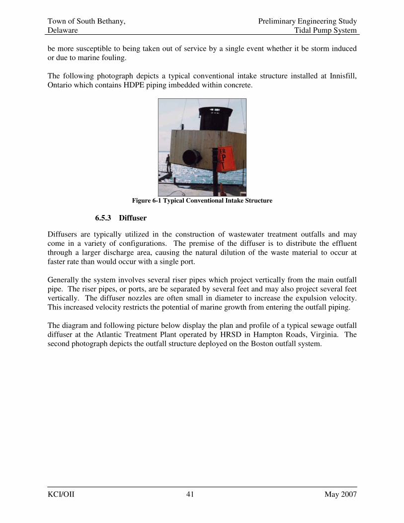
Town of South Bethany, Preliminary Engineering Study Delaware Tidal Pump System
KCI/OII 41 May 2007
be more susceptible to being taken out of service by a single event whether it be storm induced or due to marine fouling. The following photograph depicts a typical conventional intake structure installed at Innisfill, Ontario which contains HDPE piping imbedded within concrete.
Figure 6-1 Typical Conventional Intake Structure
6.5.3 Diffuser
Diffusers are typically utilized in the construction of wastewater treatment outfalls and may come in a variety of configurations. The premise of the diffuser is to distribute the effluent through a larger discharge area, causing the natural dilution of the waste material to occur at faster rate than would occur with a single port. Generally the system involves several riser pipes which project vertically from the main outfall pipe. The riser pipes, or ports, are be separated by several feet and may also project several feet vertically. The diffuser nozzles are often small in diameter to increase the expulsion velocity. This increased velocity restricts the potential of marine growth from entering the outfall piping. The diagram and following picture below display the plan and profile of a typical sewage outfall diffuser at the Atlantic Treatment Plant operated by HRSD in Hampton Roads, Virginia. The second photograph depicts the outfall structure deployed on the Boston outfall system.
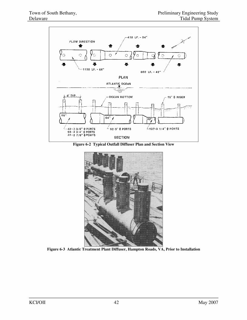
Town of South Bethany, Preliminary Engineering Study Delaware Tidal Pump System
KCI/OII 42 May 2007
Figure 6-2 Typical Outfall Diffuser Plan and Section View
Figure 6-3 Atlantic Treatment Plant Diffuser, Hampton Roads, VA, Prior to Installation

Town of South Bethany, Preliminary Engineering Study Delaware Tidal Pump System
KCI/OII 43 May 2007
Figure 6-4 A Diffuser Head Deployed on the Boston Outfall
Diffusers can be of variable designs such as a “Y” or “T” outlet, a pipe length in which holes have been drilled on top of the pipe within 10 and 2 o’clock, or a pipe length onto which vertical risers consisting of short sections of smaller diameter pipe have been installed. Diffusers are often designed for connection to the pipe by means of flange assemblies. The connection can be made prior to launching, or by divers after the pipeline has been submerged. Care is necessay in the submersion of a marine line with an engineered diffuser attached to the pipeline which is being sunk in place. The sinking process can create considerable stresses on the fittings that may be inherent to the design of the diffuser itself such as flanges, tees and/or other mechanical connections. A preferred method when placing a diffuser into a marine pipeline is to first sink the flanged pipe and then submerge the diffuser separately in easily controlled segments which may be connected to the main pipe underwater using qualified diving contractors. For the TP system the diffuser concept is a viable option. The general configuration would stay the same; however, the diffuser nozzles would be designed with a wider opening to reduce the expulsion velocity, since the intake/outfall pipe must also draw in water. In drawing in water the design should focus on reduced intake velocity to decrease the potential for marine fouling organism entrainment. A diffuser configured for the TP system can also be designed with only a few riser ports since the effluent will not be sewage and thus spreading the fluid is not critical to the design. Multiple ports will be important for redundancy incase one is damaged or disabled through navigation (anchor or trawler impact), marine fouling, or sediment intrusion. Thus a diffuser system with a at least 3 ports would be most practical. Riser height from the seabed would necessarily be based upon design calculations to be completed during the design phase; however, likely height would be between 3 to 5 feet.
In the diffuser configuration the main pipe is either left exposed or buried in the bottom for maintenance of stability. Deployment for a TP diffuser would be based upon the specific diffuser geometry compared with expected current forces which would be calculated during the engineering design phase of the project.
6.5.4 Elmosa Marine Works - InvisiHead system
The InvisiHead system, manufactured by Elmosa Marine Works of Canada is an intake/outfall system designed to minimize intake and outfall velocities. The system is adjustable and
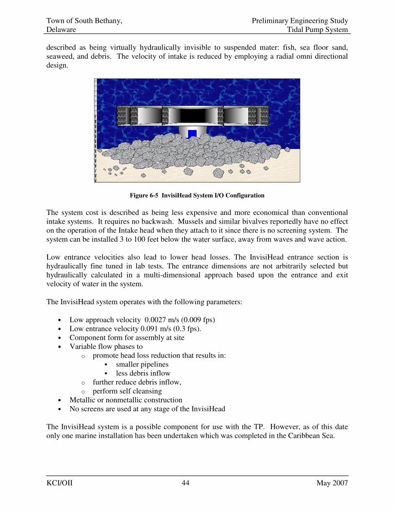
Town of South Bethany, Preliminary Engineering Study Delaware Tidal Pump System
KCI/OII 44 May 2007
described as being virtually hydraulically invisible to suspended mater: fish, sea floor sand, seaweed, and debris. The velocity of intake is reduced by employing a radial omni directional design.
Figure 6-5 InvisiHead System I/O Configuration
The system cost is described as being less expensive and more economical than conventional intake systems. It requires no backwash. Mussels and similar bivalves reportedly have no effect on the operation of the Intake head when they attach to it since there is no screening system. The system can be installed 3 to 100 feet below the water surface, away from waves and wave action.
Low entrance velocities also lead to lower head losses. The InvisiHead entrance section is hydraulically fine tuned in lab tests. The entrance dimensions are not arbitrarily selected but hydraulically calculated in a multi-dimensional approach based upon the entrance and exit velocity of water in the system.
The InvisiHead system operates with the following parameters:
• Low approach velocity 0.0027 m/s (0.009 fps) • Low entrance velocity 0.091 m/s (0.3 fps). • Component form for assembly at site • Variable flow phases to
o promote head loss reduction that results in: � smaller pipelines � less debris inflow
o further reduce debris inflow, o perform self cleansing
• Metallic or nonmetallic construction • No screens are used at any stage of the InvisiHead
The InvisiHead system is a possible component for use with the TP. However, as of this date only one marine installation has been undertaken which was completed in the Caribbean Sea.
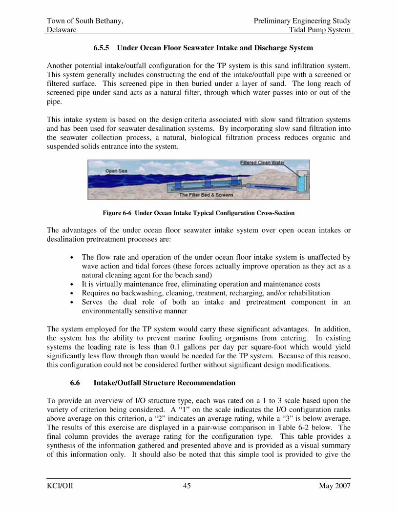
Town of South Bethany, Preliminary Engineering Study Delaware Tidal Pump System
KCI/OII 45 May 2007
6.5.5 Under Ocean Floor Seawater Intake and Discharge System
Another potential intake/outfall configuration for the TP system is this sand infiltration system. This system generally includes constructing the end of the intake/outfall pipe with a screened or filtered surface. This screened pipe in then buried under a layer of sand. The long reach of screened pipe under sand acts as a natural filter, through which water passes into or out of the pipe.
This intake system is based on the design criteria associated with slow sand filtration systems and has been used for seawater desalination systems. By incorporating slow sand filtration into the seawater collection process, a natural, biological filtration process reduces organic and suspended solids entrance into the system.
Figure 6-6 Under Ocean Intake Typical Configuration Cross-Section
The advantages of the under ocean floor seawater intake system over open ocean intakes or desalination pretreatment processes are:
• The flow rate and operation of the under ocean floor intake system is unaffected by wave action and tidal forces (these forces actually improve operation as they act as a natural cleaning agent for the beach sand)
• It is virtually maintenance free, eliminating operation and maintenance costs • Requires no backwashing, cleaning, treatment, recharging, and/or rehabilitation • Serves the dual role of both an intake and pretreatment component in an
environmentally sensitive manner
The system employed for the TP system would carry these significant advantages. In addition, the system has the ability to prevent marine fouling organisms from entering. In existing systems the loading rate is less than 0.1 gallons per day per square-foot which would yield significantly less flow through than would be needed for the TP system. Because of this reason, this configuration could not be considered further without significant design modifications.
6.6 Intake/Outfall Structure Recommendation
To provide an overview of I/O structure type, each was rated on a 1 to 3 scale based upon the variety of criterion being considered. A “1” on the scale indicates the I/O configuration ranks above average on this criterion, a “2” indicates an average rating, while a “3” is below average. The results of this exercise are displayed in a pair-wise comparison in Table 6-2 below. The final column provides the average rating for the configuration type. This table provides a synthesis of the information gathered and presented above and is provided as a visual summary of this information only. It should also be noted that this simple tool is provided to give the
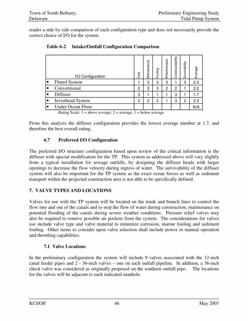
Town of South Bethany, Preliminary Engineering Study Delaware Tidal Pump System
KCI/OII 46 May 2007
reader a side by side comparison of each configuration type and does not necessarily provide the correct choice of I/O for the system.
Table 6-2 Intake/Outfall Configuration Comparison
I/O Configuration Cost
Main
tenance
Foulin
g
Eff
ectiveness
Constr
ucta
bili
ty
Surv
ivabili
ty
Avera
ge
• Fluted System 1 3 3 3 1 3 2.3
• Conventional 2 3 3 2 2 1 2.2
• Diffuser 3 1 1 1 3 1 1.7
• Invisihead System 3 3 2 1 3 2 2.3
• Under Ocean Floor N/A Rating Scale: 1 = above average; 2 = average; 3 = below average
From this analysis the diffuser configuration provides the lowest average number at 1.7, and therefore the best overall rating. 6.7 Preferred I/O Configuration
The preferred I/O structure configuration based upon review of the critical information is the diffuser with special modification for the TP. This system as addressed above will vary slightly from a typical installation for sewage outfalls, by designing the diffuser heads with larger openings to decrease the flow velocity during ingress of water. The survivability of the diffuser system will also be important for the TP system as the exact ocean forces as well as sediment transport within the projected construction area is not able to be specifically defined.
7. VALVE TYPES AND LOCATIONS
Valves for use with the TP system will be located on the trunk and branch lines to control the flow into and out of the canals and to stop the flow of water during construction, maintenance on potential flooding of the canals during severe weather conditions. Pressure relief valves may also be required to remove possible air pockets from the system. The considerations for valves use include valve type and valve material to minimize corrosion, marine fouling and sediment fouling. Other items to consider upon valve selection shall include power or manual operation and throttling capabilities.
7.1 Valve Locations
In the preliminary configuration the system will include 9 valves associated with the 12-inch canal feeder pipes and 2 - 36-inch valves – one on each outfall pipeline. In addition, a 36-inch check valve was considered as originally proposed on the southern outfall pipe. The locations for the valves will be adjacent to each indicated manhole.
Town of South Bethany, Preliminary Engineering Study Delaware Tidal Pump System
KCI/OII 47 May 2007
To facilitate ease of maintenance through easy access, the possible location for the canal side valves would be at the head of each canal pipe. In this location the valves could be accessed for maintenance without having to remove the assembly. The other potential location for the canal side valve would be adjacent to the “tee” which connects the canal feeder to the trunk line. In this location the feeder line could be isolated from the system. This would facilitate cleaning or preparing the line while the remainder of the system is in operation. At this location, the valve would be direct buried with a roadway box for valve operation. This installation would require more cost if the valve had to be accessed for maintenance. The valves for the ocean side portion of the system would be located adjacent to the sea-side manholes. These valves would be utilized to throttle or shut off flow. The valve would be placed inside a valve vault. At the south outfall pipe, the valve would also be located on the ocean-side of the check valve. The TP system is not intended to be throttled under normal operations. Throttling involves partial closure of a valve to restrict and increase flow velocity. Should restriction or transition of flow to portions of the system be necessary, a valve can be fully closed during a tide cycle or series of tide cycles to equalize flow. Generally valves designed for throttling flows significantly effect head loss of a system, such as with the globe valve described below. Thus, the high head penalty associated with such valves would effectively remove them from consideration for the TP system.
7.2 Valve Types
7.2.1 Gate Valves
Gate valves are used when a straight-line flow of fluid and minimum restriction is desired. Gate valves are so named because the part that either stops or allows flow through the valve acts somewhat like the opening or closing of a gate and is called the gate. The gate is usually wedge shaped. When the valve is wide open, the gate is fully drawn up into the valve body, leaving an opening equivalent to the full diameter of the pipe. Therefore, there is little pressure drop or flow restriction through the valve. This is also important because the valve will allow for access of cleaning devices. Gate valves are not suitable for throttling purposes in general flow conditions since the control of flow would be difficult due to valve design and since the flow of fluid slapping against a partially open gate can cause extensive damage to the valve. The low velocity expected in the TP system, however may allow use of throttling with gate valves if necessary. This consideration can be addressed during the design phase.
Gate valves would be the most likely choice for use within the TP system since they deliver minimal head loss to the system compared with globe valves. In addition, the gate valves use for stopping flow is appropriate vs. a throttling type valve which would not be necessary.
7.2.2 Globe Valves
The flow path through globe valves follows a changing course, thereby causing increased resistance to flow and considerable head loss. Because of the seating arrangements, globe valves are the most suitable for throttling flow. The valve is named after its globular body. Due to the
Town of South Bethany, Preliminary Engineering Study Delaware Tidal Pump System
KCI/OII 48 May 2007
head loss inherent in the globe valve and its use for throttling, this type of valve will not be applicable for the TP system.
7.2.3 Check Valve
Installation of a check valve for the south outfall pipe would function to restrict flow to the seaward direction only. Check valves installed for this purpose are sometimes referred to as tide valves. Due to the relatively small head differential inherent in the TP system, the check valve would have to be automatically actuated to function effectively.
7.2.4 Pressure Relief Valves
Pressure relief valves are generally placed within a water or sewer force main system to remove air which may have accumulated within the system. The trapped air functions as a blockage to water flow, reducing the functional cross-sectional area of the pipe and resulting in reduced system capacity. This air will collect within a high point in the system and would be released by a simple pressure activated valve which automatically functions to dissipate the trapped air.
In general the TP system is to be constructed at flat grade 4 feet below mean sea level with piping which dives to 30 feet below mean sea level out the intake/outfall structures. Because of the flat grade, no high points should exist in the system. Additionally the system will always be fully submerged so entrainment of air pockets will be unlikely. Consequently, it is recommended that the TP system not be equipped with pressure relief valves.
7.3 Valve Operations
Valves can be operated through automation or by manual methods. The reasons automation may be implemented for a TP type system would include the need to operate the valve often or if a quick response may be needed to shift or stop system flows for any reason. In addition, as in the case of the check valve, automation/actuation may be needed in cases where a flap or check valve will not operate efficiently because of low system head. Automation of valves adds costs associated with increased maintenance which counters the stated goals of providing a system which minimizes maintenance. O&M for a manually operated valve may entail as little as making sure the valve is operated once a year to prevent seizure by corrosion or fouling. The initial capital cost of manually operated valves will also be lower than their automated counter-parts. Automatically actuated valves suitable for use in the system could be electrically powered with manual override capability. A typical industry automated 36” gate valve system is currently manufactured by DeZurik, which could potentially be utilized in the TP system.
7.4 Valve Material
Valves within the TP system should be constructed of corrosion resistant material, should not interfere with cleaning operations, and should be easily maintained. Copper nickel or HDPE are applicable for use with the system. HDPE valves are generally not manufactured greater than
Town of South Bethany, Preliminary Engineering Study Delaware Tidal Pump System
KCI/OII 49 May 2007
16” in diameter, but may be appropriate for the 12” canal valves. The larger valves would most likely be copper nickel or other marine acceptable material.
7.5 Valve Recommendations
It is recommended that the TP system utilize valve situated near the manholes as described above. For safety, it is recommended to provide automatically actuated electric controls for the two 36” ocean-side valves. This will allow for quick system closure for any reason. The valves should also have a manual override ability. Since 36-inch valves are generally not manufactured in HDPE, it is recommended that a 36” copper nickel valve be used. For the canal feeder line valves, manually actuated HDPE valves are recommended. 8. OPERATIONS AND MAINTENANCE
Maintenance of the system will involve regular cleaning to prevent buildup of marine growth and possible sediment intrusion as well as valve operation and maintenance. Operations of the system will be monitored by a portable propeller flowmeter, otherwise there will be no other elements needing regular attention.
8.1 Flow Monitoring
The most efficient and simplest way to ascertain the performance of the TP system and the extent of marine fouling may be effecting operations is to provide regular flow monitoring of the system. This monitoring could be as simple as placing a portable flow meter into the flow area of one of the canal feeder lines at either high ocean tide or high canal tide on a regular basis. The frequency of flow readings could be set arbitrarily by the Town, for example, either per day, week, 2-weeks, or month. Total reading time should be taken over at least a 5 minute period to obtain an average and avoid recording instantaneous peaks or lull in flow. This monitoring would be initiated at initial start up of the system to set a baseline with which to compare future flow data. The data accumulated through this flow monitoring would essentially be the means by which further inspections or cleaning are triggered. The point at which the decision to clean or inspect the system could be arbitrarily set by the Town, but may reflect a reduction in flow of 50% or similar parameters. Also key to this system will be the regular recording of flows and an effective means of maintaining the flow records. The type of flowmeter being proposed for use is a propeller meter on a fixed rod. This device could be mounted on a specific bracket affixed to each or some of the canal feeder line intakes to the system. The propeller meter would be simple to maintain and calibrate. Also, it would be more cost effective for the Town than an automated system which would incur much greater initial capital expense to the system, be less mobile, and would itself have a large maintenance component associated with use.
8.2 Maintenance
As described in Section 2 above the system will be constructed in a closed pipe network manner. Access for cleaning will be gained through bolted caps placed within the manholes. These caps will only be removed for cleaning operations.
Town of South Bethany, Preliminary Engineering Study Delaware Tidal Pump System
KCI/OII 50 May 2007
8.3 Manholes
A system of 12 manholes situated at the intersection of the 12-inch canal feeder lines and the 36-inch trunk line will be a critical component to allow for maintenance of the system (see Figure 2-1 to 2-3 for locations). Additional manholes will be positioned on the shore side of the outfall/intake and outfall pipes. These manholes will allow for entrance of remote cleaning devices which will be able to span each pipe reach to clean out accumulated debris and marine growth. These manholes can be constructed using typical methods used for sanitary sewer manholes with pre-fabricated concrete components.
8.4 System Cleaning
The ability to clean the piping will be critical to maintaining the system. As discussed earlier the low flow velocities and slack tide time at which velocity will be essentially be zero will allow for marine growth at all points in the system. This may be reduced by using biologically inert piping material, but will not completely prohibit the growth. In addition, design of the system will require the pipe to be completely full at all points of the day during regular service, which will expose the full internal surface of the pipe to potential fouling growth. Cleaning of the system may be accomplished through various means depending upon the amount of fouling and if the pipe is to be left in its typical submerged condition or pumped dry. Cleaning methods for use in full flow submerged condition include hydraulic and mechanical means. The relative cleaning period for the system will be based upon the amount of fouling and the reduction in system performance. Many factors may influence marine growth in the system and the projected number of cleanings and frequency. Due to limited experience with this type of system, only an educational estimation can be utilized to establish a cleaning interval. For analysis purposes, KCI/OII projects cleaning of the system will be required once a year.
8.5 Cleaning Techniques
A range of cleaning techniques are available for piping similar to the TP system. The TP system could effectively be cleaned by hydraulic or mechanical methods, or a combination of both. The design phase of the project will involve further detail regarding specific cleaning methods as well as availability. However, the methods outlined below provide a range of possible applications which may be used to clean the system depending on the amount and type of fouling. 8.5.1 Hydraulic Method
The hydraulic cleaning technique employs high-pressure water, which is passed through a specially designed jetting head attached to a pressure hose fed from a surface pump. The system allows the jetting head to be passed through a pipe at any speed desired. The pressure head is designed so that the water sprays out of it to hit the inner wall of the pipeline, dislodging attached material. This application can be employed both in full and dry systems, however greater water pressure is needed in submerged conditions. The debris created, is then pushed
Town of South Bethany, Preliminary Engineering Study Delaware Tidal Pump System
KCI/OII 51 May 2007
back through the pipe, either by the passage of the head as it is pulled through the pipe or by the flushing action of the used water as it flows through the pipe. The cleaning equipment usually includes a vacuum and storage capability which allows the debris to be sucked from a manhole. All the necessary equipment is normally mounted on specialized cleaning vehicles or trailers. At higher pressures the water in the jets can be sufficient to cut through solid material. Where the material is too solid and standard jetting equipment is unable to remove it there are specially designed remote controlled robots available that use very high pressure, low volume water jets or rotating cutter blades for the removal process.
8.5.2 Mechanical Cleaning
Rodders
Mechanical cleaning involves the use of some type of physical device that scrapes, cuts, or pulls material from the pipe. One of the oldest cleaning methods, called hand rodding, is the most labor-intensive method of mechanical cleaning. Small engine-powered rodding machines are now available. These machines are inexpensive and provide an effective method of cleaning in smaller systems and also in remote easements or right-of-way areas where large equipment cannot gain access. Larger mechanical power Rodders are equipped with a reel to carry the steel rods and an engine to provide the force to rotate, push, and pull the steel rods. Power Rodders are available in both truck-mounted and trailer-mounted models and a variety of different engine sizes are available for each type of unit. Power Rodders can clear most obstructions. The tools are designed to cut or scrape materials from the pipe walls and are most effective on hardened material. The power rodder is not as effective when working with deposits of solids such as sand or gravel because the tools do not have the ability to move the material. Bucket Machines
Power bucket machines are another type of mechanical cleaning device; they are used to remove debris, hardened material, or sediments from main line sewers. A bucket machine is equipped with a set of specialized winches that pull a special bucket through a pipe to collect debris. The captured materials are then physically removed from the pipe. These machines are very powerful and offer the best cleaning method with the least opportunity for operator error that could affect the results. Since a piped-sized cutter and brush can be pulled through the line, each cleaning is thorough and no residual debris is left in the pipeline. Scraping
Scraping is a commonly used technique, which relies on a pipeline being open sufficiently to pass a winch wire through it. Once in place a scraper head, normally a circular rubber or metal device, in the form of a wire brush or metal sheet or rubber shape that may or may not have some form of serration on the cutting edge, is attached to the wire and pulled through the pipe. The scraper dislodges any build-up of material and, as it is normally sized to the internal diameter of the pipe, it pulls the debris to the end of the pipeline into the winching access area. Where necessary the static scraper head can be replaced by a flail attached to a rotating rod. The flail, often called a chain cutter, dislodges any unwanted material which falls into the invert of the pipe. Jetting or flushing may then be used to remove the debris.
Town of South Bethany, Preliminary Engineering Study Delaware Tidal Pump System
KCI/OII 52 May 2007
Where the pipe is heavily encrusted with material it may not be possible to insert the winch wire and a system such as a Rack Feed Boring must be used. This uses a boring head attached to a series of drive rods, which are used to rotate a boring head. The system is pushed into the pipe, and water flushed in the opposite direction, to clear the debris. Pigging
Where the main cleaning work has been successful, sometimes a pipe requires a final inner wall surface clean. To achieve this, a pipe ‘pig’ can be employed. A pig is often a foam or plastic cylindrical plug that fit tightly, but not too tightly, in the internal diameter of a pipeline. The pig is pushed through the pipe, using compressed air or water pressure; to remove any remaining fine silts or particles. On some pipelines, ‘pigging’ can be used as the main cleaning technique, and is regularly used in the cleaning of plastic pipelines such as HDPE. Pigs used for the main cleaning action can have smooth outer skins or can be manufactured with a variety of external designs for removing debris from the pipe wall and transporting it out of the pipe. The pigging can be completed by service companies which specialize in the cleaning of sanitary sewer or water infrastructure. 9. BUDGETARY ESTIMATES
Budgetary cost estimation for the project elements has been completed by OII/KCI to provide the Town with the relative expenses which may be incurred through design, construction and maintenance of the TP system.(See Attachment – Cost Estimate Sheets section) These estimates have been broken into design, construction and maintenance tables and are included in the Attachments to this report. The estimates are based upon the system with a 1,600 foot I/O pipe incorporated at both the north and south end. The design cost estimate can be expected to stay relatively fixed regardless of the material/ installation options. For this reason there is one expected engineering design cost estimate which does not vary between the three costing sheets. This cost is based on the average billing rate to be expected for personnel working on the project as well as estimated hours to accomplish each task. All the tasks are identified on the estimation chart. Environmental permitting work for the project remains ambiguous at present pending discussions with DNREC. Thus, this item has been estimated at a high amount of hours. The total engineering design budgetary estimate is approximately $249,000. The maintenance cost estimate is based upon providing cleaning of the system on an annual basis as well as the effort to utilize the flow meter and track performance and test valves on an annual basis. In addition an estimate for manual operation of valves for a total of three days a year is also included which reflects having to shut valves for storm or to isolate system components. As discussed above, due to the variables of marine fouling and sedimentation and resulting impacts to the system once constructed, the specific effort needed to provide O&M will not be know until the system is in operation. This portion of the budgetary estimate, as such, may vary
Town of South Bethany, Preliminary Engineering Study Delaware Tidal Pump System
KCI/OII 53 May 2007
significantly from this projection based upon future operational knowledge and should be so noted when reviewing this estimate. The annual O&M budgetary is estimated at $18,410. Three budgetary construction cost estimates have been produced based upon the use of the recommended piping material of HDPE being installed through open trench, HDD methods on land and variations for ocean installation. For the beach crossing the estimates reflect the cost of use of HDD paired with HDD, float and sink, or dig and lay options for the ocean installation. Open trench construction through the beach transition area with the use of sheet pilling has not been included in the estimates due to the high cost, which would be approximately $800,000 for one 36” crossing, and the negative visual perception of this method. The budgetary construction cost estimates range from $5.2 million to $6.7 million. In addition, an option exists for phasing the project as discussed in section 2.7 by only constructing the north I/O pipe first, which could potentially eliminate an estimated $1.6 million in initial Phase construction costs. Should the south outfall be determined to be necessary to achieve goals established for maintain canal flushing, it could be constructed as a Phase II project in the future.
10. PROJECT SCHEDULE
The project schedule is included in the Attachment sections and provides a tentative schedule for the design as well as construction portions of the project. The schedule has been based upon completion of engineering design in an eight month period, from July 2007 to March 2008. Bidding services would encompass two months, with an award by early May 2008. According to the Town’s intentions, construction would not be permitted to begin until after Labor Day. Thus, the schedule reflects construction beginning in September 2008 and continuing for an estimated 7 ½ month period until mid-March 2009. Confirmatory testing of the system would then be undertaken by the engineering design firm to be completed in June 2009. As in the cost estimation portion, the potential time frame for environmental permitting remains to be determined through discussion with DNREC and USACE. The schedule does provide for a possible extension for additional permitting time created by the construction prohibition between Memorial Day and Labor Day. In the case of the preliminary schedule this buffer time would occur during the summer of 2008.
11. CONCLUSION
11.1 Summary of Report Conclusions
The South Bethany Beach Tidal Pump System provides a simple design to utilize the existing tidal differential between the Atlantic Ocean and the canals of South Bethany to circulate water via a network of underground pipes connecting the two bodies of water. The circulation of the water is meant to improve the water quality within the canals, which has deteriorated due to poor flushing action and dead end canals contained within the inland Bay network. This preliminary engineering and budgetary cost study was undertaken to provide an analysis of all aspects of the proposed system. For the project the KCI/OII team performed a hydraulic
Town of South Bethany, Preliminary Engineering Study Delaware Tidal Pump System
KCI/OII 54 May 2007
analysis of the system and possible alternative configurations; provided an analysis of environmental factors which may affect the TP system; addressed potential permitting requirements; provided an analysis of potential pipe materials, installation methods, valve types and locations; and identified operations and maintenance issues. From this compiled information budgetary estimates and preliminary scheduling was developed. The hydraulic analysis of the system sought to provide feedback not obtained through previous system modeling by comparing varying system configurations and conditions. The overall result of the hydraulic modeling of the system verified that the system is a viable means to move water between the ocean and the canals. The analysis also identified potential modifications that could be employed to the system should the Town wish to implement them. These potential modifications included reducing the I/O piping from two to one, varying canal feeder pipe diameters, removing the prescribed check valve, or providing dual piping for the I/O piping. The affects to the system from these modifications was presented in tabular form for review and consideration for the final design selection. From the information gathered, OII/KCI recommended constructing the system as originally configured without a check valve and extension of the south I/O piping 1,600 feet offshore. In addition, the possibility of constructing the system in two phases was discussed. The environmental factors affecting the proposed system area do not present any specific technical problems for construction and operation. The wave climate along the coast is average for the Atlantic coast and thus will be within potential contractor abilities. The seabed, although not geotechnically analyzed for the budgetary cost study, is expected to be compact sand throughout the project area. The land based portions of the project would expect to encounter sandy soil with a high groundwater table. OII/KCI recommends performing a full geotechnical investigation as part of the engineering design to ascertain exact site conditions which will be critical knowledge for the final system design and installation. Marine fouling and potential sedimentation within the system were also identified as a significant factor in maintaining system performance. Corrosion of metallic components induced by the marine environment was noted as a reason to employ non-corrosive plastic (inert) components where practical. Environmental permitting will be a significant component to system design. OII/KCI recommended communication with regulators as soon as possible to ascertain the exact permitting requirements that will be required. A list of potential permits and regulating bodies that would likely be involved has been provided. Easement issues will be minimal for the proposed alignment and may require the taking of only one where the north I/O proceeds to the beach along North Sixth Street.
Analysis of potential pipe material identified HDPE as the most viable material for the TP system. HDPE was identified for this project because of several properties including buoyancy, inert behavior, natural resistance to biofouling compared with other choices, inert/ non-corrosive to sea water, and flexibility for installation, high strength, resilience to shock, high fatigue strength, and almost unlimited life expectancy underwater.
Potential installation methods for all components of the system were reviewed. For the beach crossing portion of the project it is recommended that HDD be used to reduce the impact to the beach front area. The land based construction is recommended to be completed through open cut
Town of South Bethany, Preliminary Engineering Study Delaware Tidal Pump System
KCI/OII 55 May 2007
trenching except for the necessary tunneling portions under Route 1 which may utilize HDD, microtunneling, or bore-and-jack methods. It was recommended that the corridor along North Sixth Street, be installed via HDD as well.
The most cost effective means to complete the offshore portion of the work appears to be the float and sink method. However due to the potential variability of contractor skills and potential pricing based upon experience, OII/KCI recommends allowing contractor selection of a method of installation for the offshore portion of the system. As several installation methods are viable for this project, availing various installation methods will encourage a larger pool of bidders with specific expertise that will provide a competitive bidding climate.
The recommended I/O structure configuration consists of a diffuser with special modification for the TP. This system will vary from a typical installation that would be applied to a sewage outfall since the diffuser heads will necessarily be designed with larger openings to decrease the flow velocity when the head is receiving water. The survivability of the diffuser system will also be important for the TP system to protect against potential ocean forces and sedimentation. Relative configuration of the concrete diffuser-like structures will include minimally 3 riser pipes projecting approximately 3 to 5 feet above the seabed.
Valves for use with the TP system are to be located on the trunk and branch lines. The system will include 9 valves associated with the 12-inch canal feeder pipes and a 36-inch valve on the shore side of the 36-inch ocean intake/outfall and outfall pipes. A 36-inch check valve positioned on the southern outfall pipe in the original configuration is not recommended and has been eliminated from the final configuration. The canal feeder line valves are to be located adjacent to the manholes. All valves associated with the system are recommended to be gate type valves of either HDPE for the 12” and copper nickel for the 36”. In addition, it is recommended that the 12” valves be manually actuated to reduce potential maintenance issues. The 36” valves for potential emergency purposes are to be automatically actuated with manual backup to allow for quick closing. Operations and Maintenance of the system is to be based upon keeping a periodic record of flow through the use of a portable propeller type flow meter. This device will be portable for monitoring at different locations with a record of flow velocity variation being maintained to gauge the cleaning cycle for the system. For budgetary purposes, OII/KCI has estimated cleaning of the system will be need on an annual basis, however actual operational performance may vary. Access for cleaning will be through manholes to be constructed throughout the system at the intersection of the trunk and feeder lines. These manholes will include a flanged cap which can be removed to access the pipe for cleaning by either hydraulic or mechanical means. The manholes would be constructed of prefabricated concrete components to reduce system cost. The system valves will also need to be exercised on an annual basis to maintain function. The budgetary estimate for the project is based upon the original configuration with an extension of the south I/O pipe and the recommendations provided within this document for pipe material and installation methods. These cost estimates provide an engineering design services estimate of approximately $249,000 with a construction estimate ranging from $5.2 to $6.7 million. In addition, by phasing the project and constructing the north I/O pipe first, this could potentially
Town of South Bethany, Preliminary Engineering Study Delaware Tidal Pump System
KCI/OII 56 May 2007
eliminate an estimated $1.6 million in the initial Phase of construction. The annual O&M estimate for the system based on annual cleaning is approximately $18,400. The preliminary project schedule involves eight months for engineering design and permitting and an additional two months for bidding and contract award. Construction of the system is projected to take approximately 7 ½ months while confirmatory testing would take additional two months to complete.
11.2 Summary of System Recommendations
• All piping shall be HDPE.
• All canal feeder lines shall be 12”. Installation of feeder lines will be performed through HDD, microtunnelling or bore-and-jack method for crossing Route 1. The remaining length may be installed via open trench or continuation of trenchless installation.
• The system will be configured with a 1,600-foot offshore intake/outfall pipe located at both the north and south end of the system.
• The trunk line piping shall be 36”. Installation of the shore side elements of the trunk line shall be installed via open trench where possible. Road crossings shall be performed through HDD, microtunnelling or bore-and-jack method. HDD is recommended for installation along North 6th Street as well as through the beach crossing zone. Offshore installation is recommended to utilize either HDD, float and sink, or dig and lay methods, with contractor given leeway to select method and cost accordingly.
• There shall be a total of 12 manholes, one for each of the nine canals and one at each end of north 6th street as well as one associated with the south I/O pipe. All manholes shall be pre-cast concrete. Each manhole shall have a bolted on cap attached to the system piping for maintenance access.
• The system shall be fitted with 9 - 12” Canal feeder gate valves which shall be HDPE, located near the canal side manholes and shall be manually actuated.
• The system shall be fitted with 2 - 36” ocean side gate valves which shall be copper nickel and located near the ocean side manholes. These valves shall be automatically actuated with electric drive and a manual override.
• The system will not be fitted with a check valve.
• Both offshore I/O pipes shall be fitted with a concrete diffuser-like outfall with approximately 3 risers 3 feet to 5 feet above the seabed. The diffuser heads shall be configured with wide ports to reduce intake and outfall velocities.
• Maintenance of the system shall be based upon monitoring of system flow through a portable type propeller meter. Cleaning of the system is expected to be necessary at least on an annual basis depending on the extent of fouling through a variety of potential means common to the water/ wastewater industry.

ATTACHMENTS

FIGURES
-30-18051010
5
0
15
051010
5
0
15
PROP. 36" PIPE
PROP.
36" PIPE
12"
12"
12"
12"
12"
12"
12"
12"
FENWICK ISLANDSTATE PARK
1
ATLANTIC OCEAN
OVERVIEW PLAN
ASSAWOMAN BAY
2
APPROVED BYDRAWN BY SCALE DATE KCI JOB NUMBER
FIGURE NO.
RWJ 010700791:500’CLO
TOWN OF SOUTH BETHANY, DELAWARE
TIDAL PUMP SYSTEM
BUDGETARY COST STUDY
OCEANEERING
R
APRIL 2007
WATER
WATER
SEWER
GAS
2" GAS
WATER
GAS
WATER
PROP. 12" PIPE
WATER
GAS
WATER
PROP. 12" PIPE
WATER
SEWER
GAS
WATER WATER
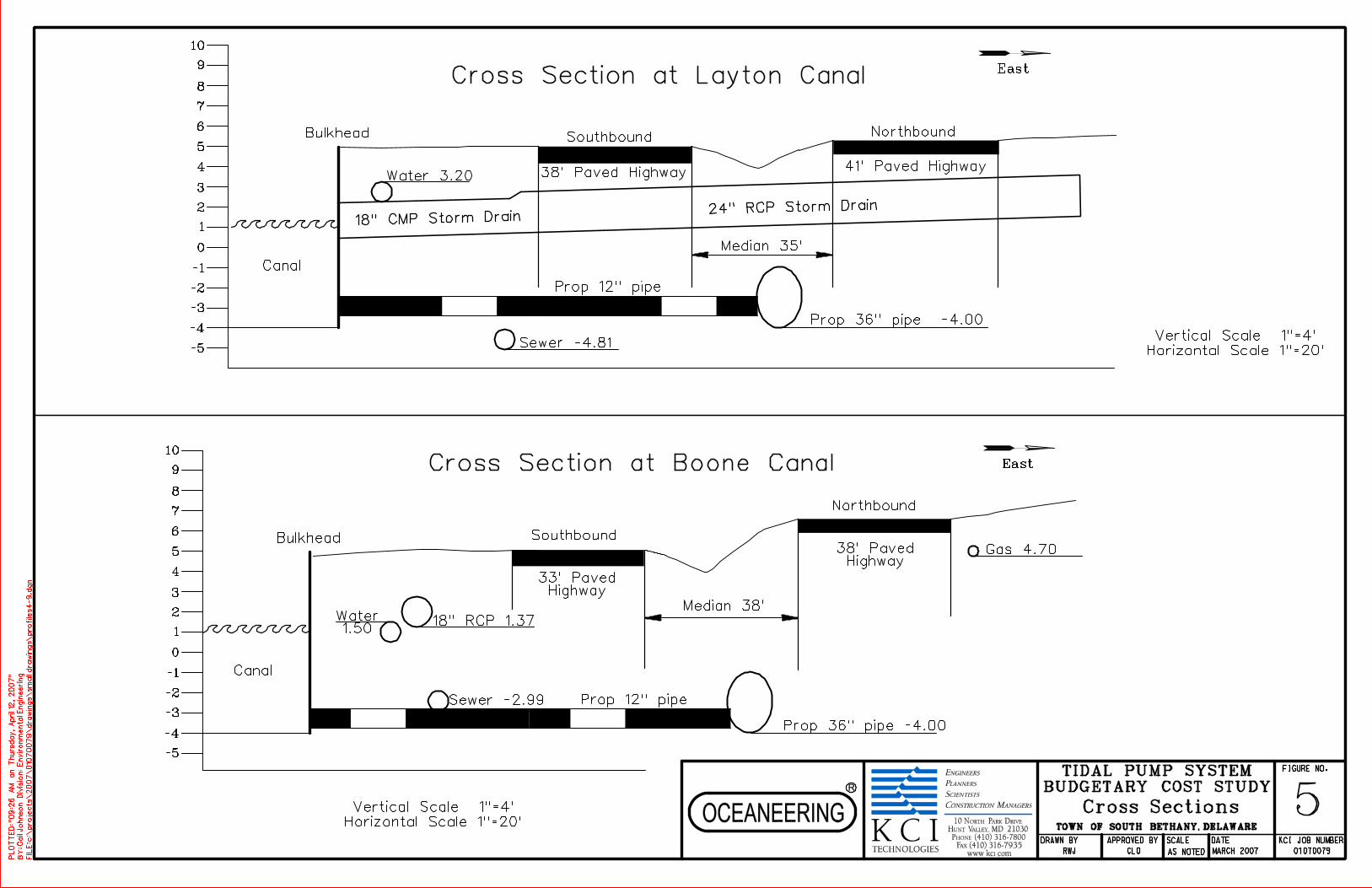
-2
5
0
1
-1
-3
2
3
4
6
7
8
9
-4
-5
10
Median 35’
NorthboundSouthbound
Median 38’
Southbound
Northbound
East
East
-2
5
0
1
-1
-3
2
3
4
6
7
8
9
-4
-5
10
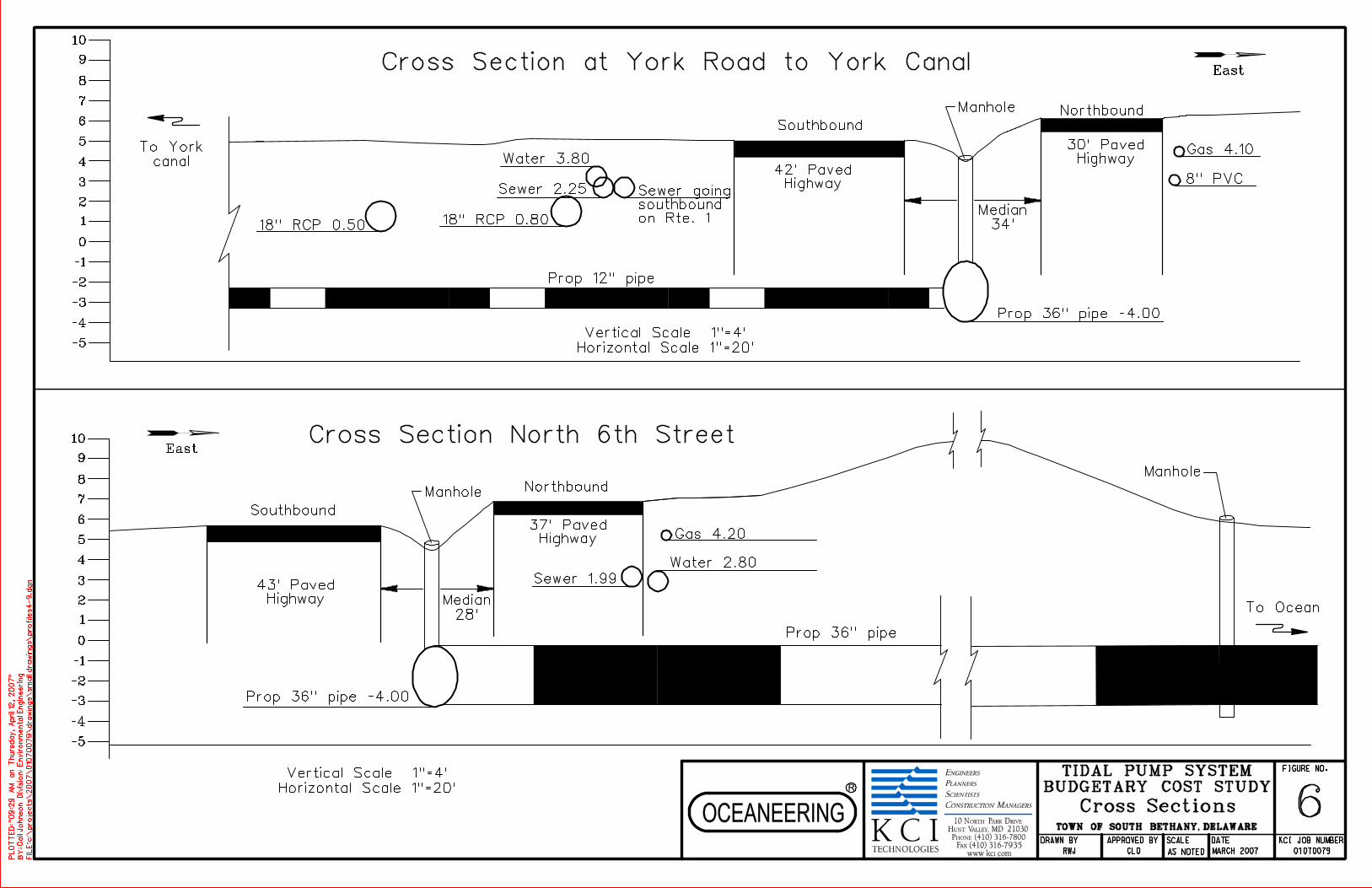
Northbound
Southbound
Manhole
Northbound
Southbound
Manhole
Manhole
-2
5
0
1
-1
-3
2
3
4
6
7
8
9
-4
-5
10
-2
5
0
1
-1
-3
2
3
4
6
7
8
9
-4
-5
10
East
East
Median
34’
Median
28’

COST ESTIMATE SHEETS

Town of South Bethany Beach
Tidal Pump Budgetary Cost Study
Pipe Material: HDPE
Construction Method: Horizontal Directional Drill
Work Breakdown Structure
Total Cost
WBS Code Title Item Units Unit Cost Total Hours Avg. Bill Rate Total
A Tidal Pump System
A A Engineering Design
A A A Existing Document Review 32 $ 79.00/hr $2,528.00 $2,528.00
A A B Engineering Report 89 $ 79.00/hr $7,031.00 $7,031.00
A A C Survey - Traverse & Control
A A C A - Topographic Survey & Worksheet 76 $ 79.00/hr $6,004.00 $6,004.00
A A C B - Boring Stakeout 36 $ 79.00/hr $2,844.00 $2,844.00
A A C C - Easement Document Preparation 72 $ 79.00/hr $5,688.00 $5,688.00
A A C D - Hydrographic Survey 66 $ 79.00/hr $5,214.00 $5,214.00
A A D
A A D A - Drilling and Fieldwork Drill Rig use 1 Ea. $ 11,000.00 Ea. $11,000.00 42 $ 79.00/hr $3,318.00 $14,318.00
A A D B - Laboratory Testing Testing Equipment 1 Ea. $ 3,500.00 Ea. $3,500.00 8 $ 79.00/hr $632.00 $4,132.00
A A D C - Engineering 48 $ 79.00/hr $3,792.00 $3,792.00
A A E 50 $ 79.00/hr $3,950.00 $3,950.00
A A F 520 $ 79.00/hr $41,080.00 $41,080.00
A A G 32 $ 79.00/hr $2,528.00 $2,528.00
A A H
A A H A - Plan, Profile & Details 641 $ 79.00/hr $50,639.00 $50,639.00
A A H B - Specifications 44 $ 79.00/hr $3,476.00 $3,476.00
A A H C - Construction Cost Estimates 36 $ 79.00/hr $2,844.00 $2,844.00
A A I
A A I A - Plan, Profile & Details 233 $ 79.00/hr $18,407.00 $18,407.00
A A I B - Specifications 12 $ 79.00/hr $948.00 $948.00
A A I C - Construction Cost Estimates 20 $ 79.00/hr $1,580.00 $1,580.00
A A J
A A J A - Plan, Profile & Details 113 $ 79.00/hr $8,927.00 $8,927.00
A A J B - Specifications 6 $ 79.00/hr $474.00 $474.00
A A J C - Construction Cost Estimates 6 $ 79.00/hr $474.00 $474.00
A A K 130 $ 79.00/hr $10,270.00 $10,270.00
A A L
A A L A - Procedures Document 32 $ 79.00/hr $2,528.00 $2,528.00
A A L B - Field Testing & Evaluation 180 $ 79.00/hr $14,220.00 $14,220.00
A A M Canvas Bids & Recommedation 33 $ 79.00/hr $2,607.00 $2,607.00
A A N Construction Phase Services
A A N A - Shop Drawing Review 257 $ 79.00/hr $20,303.00 $20,303.00
A A N B - Technical Consulting 105 $ 79.00/hr $8,295.00 $8,295.00A A O As-Builts 54 $ 79.00/hr $4,266.00 $4,266.00
Design Total $249,367.00
Item Units Unit Cost Total Units Unit Cost Total
A B Construction
A B A Mobilization
A B A A Staging Area (ea) 1 $0.00 1 $25,000.00 $25,000.00 $25,000.00
A B A B Material and Equipment Transfer & Setup (ea) 1 $0.00 1 $135,000.00 $135,000.00 $135,000.00
A B B Inland Construction
A B B A Civil Site Work alignment (lf) 7,036 $0.00 7,036 $22.00 $154,792.00 $154,792.00
A B B B Piping
A B B B A Intake/Outfall Line 36-inch pipe (lf) 720 $100.00 $72,000.00 720 $650.00 $468,000.00 $540,000.00
A B B B B Trunk Line 36-inch pipe (lf) 3,440 $100.00 $344,000.00 3,440 $155.00 $533,200.00 $877,200.00
A B B B C Outfall Line 36-inch pipe (lf) 850 $100.00 $85,000.00 850 $155.00 $131,750.00 $216,750.00
A B B B D Canal Feeder Lines (12") 12-inch pipe (lf) 2,026 $25.00 $50,650.00 2,026 $35.00 $70,910.00 $121,560.00
A B B C Appurtanances
A B B C A 36-inch I/O Valve 36-inch valve (ea) 2 $32,500.00 $65,000.00 2 $2,500.00 $5,000.00 $70,000.00
A B B C B 12-inch Valves 12-inch valves (ea) 9 $2,600.00 $23,400.00 9 $350.00 $3,150.00 $26,550.00
A B B C C Manholes and Assoc. Appurtenances 48-inch dia (vf) 110 $410.00 $45,100.00 110 $140.00 $15,400.00 $60,500.00
A B B C D Flowmeter (Propeller) 1 $1,989.00 $1,989.00 1 $0.00 $1,989.00
A B C Marine Construction
A B C A Floating Equipment Mobilization (ea) 1 $0.00 1 $87,000.00 $87,000.00 $87,000.00
A B C B Piping Installation
A B C B A Intake/Outfall Line 36-inch pipe (lf) 1,600 $150.00 $240,000.00 1,600 $950.00 $1,520,000.00 $1,760,000.00
A B C B B Outfall Line 36-inch pipe (lf) 1,600 $150.00 $240,000.00 1,600 $950.00 $1,520,000.00 $1,760,000.00
A B C C Outfall/Intake Installation (ea) 2 $184,000.00 $368,000.00 2 $46,000.00 $92,000.00 $460,000.00
A B D Demobilization
A B D A Demobilization of Equipment & Personnel (ea) 1 $0.00 1 $120,000.00 $120,000.00 $120,000.00A B D B Breakdown Stagging Area (ea) 1 $0.00 1 $15,000.00 $15,000.00 $15,000.00
Construction Total $1,535,139.00 $4,896,202.00 $6,431,341.00
Item Units Unit Cost Total Units Unit Cost Total
A C Operations & Maintenance (Annual Cost)
A C A Flowmeter Monitoring 104 $ 60.00/hr $6,240.00 $6,240.00
A C B Valve Maintenance 8 $ 60.00/hr $480.00 $480.00
A C C Valve Operations 24 $ 60.00/hr $1,440.00 $1,440.00A C D Cleaning Operations 5 Ea. $ 2,050.00 Ea. $10,250.00 $10,250.00
Operations & Maintenance Total $18,410.00
Project Total $6,699,118.00
Erosion & Sediment Control
Environmental Permitting
Construction Permitting
60% Level Design & Contract Documents
May 4, 2007
Geotechnical Investigation
Labor CostMaterial Cost
Material Cost Labor / Equipment
90% Level Design & Contract Documents
Bid Ready Design & Contract Documents
O&M Procedures
System Confirmatory Testing
Material Cost Labor / Equipment Cost
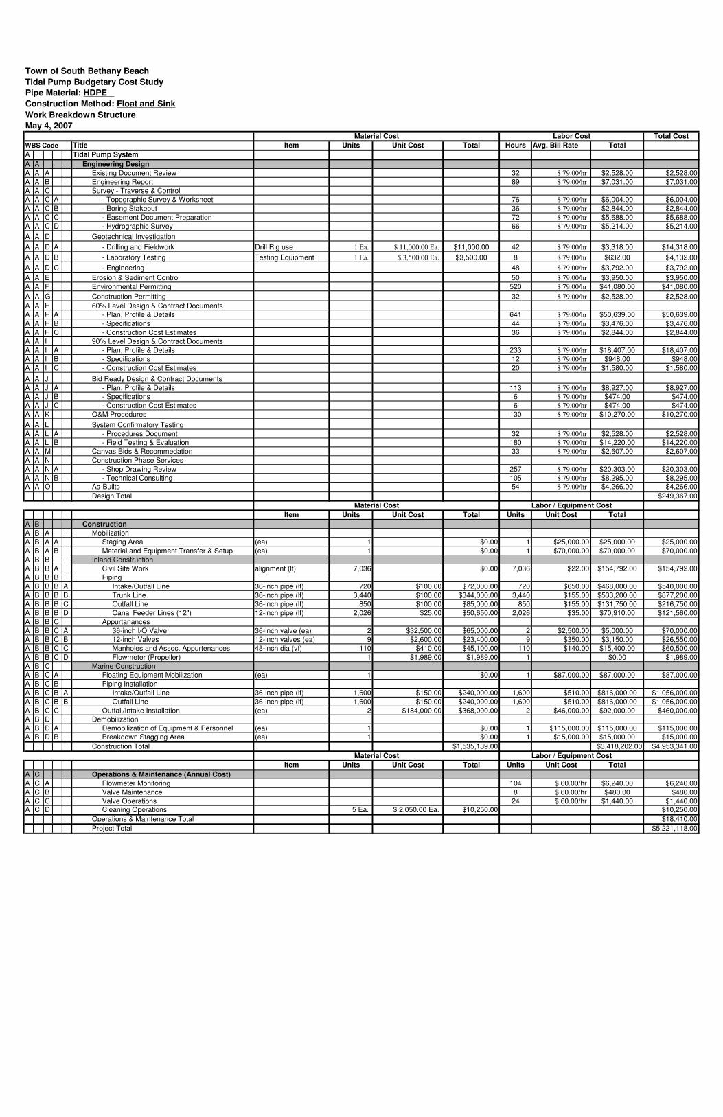
Town of South Bethany Beach
Tidal Pump Budgetary Cost Study
Pipe Material: HDPE
Construction Method: Float and Sink
Work Breakdown Structure
Total Cost
WBS Code Title Item Units Unit Cost Total Hours Avg. Bill Rate Total
A Tidal Pump System
A A Engineering Design
A A A Existing Document Review 32 $ 79.00/hr $2,528.00 $2,528.00
A A B Engineering Report 89 $ 79.00/hr $7,031.00 $7,031.00
A A C Survey - Traverse & Control
A A C A - Topographic Survey & Worksheet 76 $ 79.00/hr $6,004.00 $6,004.00
A A C B - Boring Stakeout 36 $ 79.00/hr $2,844.00 $2,844.00
A A C C - Easement Document Preparation 72 $ 79.00/hr $5,688.00 $5,688.00
A A C D - Hydrographic Survey 66 $ 79.00/hr $5,214.00 $5,214.00
A A D
A A D A - Drilling and Fieldwork Drill Rig use 1 Ea. $ 11,000.00 Ea. $11,000.00 42 $ 79.00/hr $3,318.00 $14,318.00
A A D B - Laboratory Testing Testing Equipment 1 Ea. $ 3,500.00 Ea. $3,500.00 8 $ 79.00/hr $632.00 $4,132.00
A A D C - Engineering 48 $ 79.00/hr $3,792.00 $3,792.00
A A E 50 $ 79.00/hr $3,950.00 $3,950.00
A A F 520 $ 79.00/hr $41,080.00 $41,080.00
A A G 32 $ 79.00/hr $2,528.00 $2,528.00
A A H
A A H A - Plan, Profile & Details 641 $ 79.00/hr $50,639.00 $50,639.00
A A H B - Specifications 44 $ 79.00/hr $3,476.00 $3,476.00
A A H C - Construction Cost Estimates 36 $ 79.00/hr $2,844.00 $2,844.00
A A I
A A I A - Plan, Profile & Details 233 $ 79.00/hr $18,407.00 $18,407.00
A A I B - Specifications 12 $ 79.00/hr $948.00 $948.00
A A I C - Construction Cost Estimates 20 $ 79.00/hr $1,580.00 $1,580.00
A A J
A A J A - Plan, Profile & Details 113 $ 79.00/hr $8,927.00 $8,927.00
A A J B - Specifications 6 $ 79.00/hr $474.00 $474.00
A A J C - Construction Cost Estimates 6 $ 79.00/hr $474.00 $474.00
A A K 130 $ 79.00/hr $10,270.00 $10,270.00
A A L
A A L A - Procedures Document 32 $ 79.00/hr $2,528.00 $2,528.00
A A L B - Field Testing & Evaluation 180 $ 79.00/hr $14,220.00 $14,220.00
A A M Canvas Bids & Recommedation 33 $ 79.00/hr $2,607.00 $2,607.00
A A N Construction Phase Services
A A N A - Shop Drawing Review 257 $ 79.00/hr $20,303.00 $20,303.00
A A N B - Technical Consulting 105 $ 79.00/hr $8,295.00 $8,295.00A A O As-Builts 54 $ 79.00/hr $4,266.00 $4,266.00
Design Total $249,367.00
Item Units Unit Cost Total Units Unit Cost Total
A B Construction
A B A Mobilization
A B A A Staging Area (ea) 1 $0.00 1 $25,000.00 $25,000.00 $25,000.00
A B A B Material and Equipment Transfer & Setup (ea) 1 $0.00 1 $70,000.00 $70,000.00 $70,000.00
A B B Inland Construction
A B B A Civil Site Work alignment (lf) 7,036 $0.00 7,036 $22.00 $154,792.00 $154,792.00
A B B B Piping
A B B B A Intake/Outfall Line 36-inch pipe (lf) 720 $100.00 $72,000.00 720 $650.00 $468,000.00 $540,000.00
A B B B B Trunk Line 36-inch pipe (lf) 3,440 $100.00 $344,000.00 3,440 $155.00 $533,200.00 $877,200.00
A B B B C Outfall Line 36-inch pipe (lf) 850 $100.00 $85,000.00 850 $155.00 $131,750.00 $216,750.00
A B B B D Canal Feeder Lines (12") 12-inch pipe (lf) 2,026 $25.00 $50,650.00 2,026 $35.00 $70,910.00 $121,560.00
A B B C Appurtanances
A B B C A 36-inch I/O Valve 36-inch valve (ea) 2 $32,500.00 $65,000.00 2 $2,500.00 $5,000.00 $70,000.00
A B B C B 12-inch Valves 12-inch valves (ea) 9 $2,600.00 $23,400.00 9 $350.00 $3,150.00 $26,550.00
A B B C C Manholes and Assoc. Appurtenances 48-inch dia (vf) 110 $410.00 $45,100.00 110 $140.00 $15,400.00 $60,500.00
A B B C D Flowmeter (Propeller) 1 $1,989.00 $1,989.00 1 $0.00 $1,989.00
A B C Marine Construction
A B C A Floating Equipment Mobilization (ea) 1 $0.00 1 $87,000.00 $87,000.00 $87,000.00
A B C B Piping Installation
A B C B A Intake/Outfall Line 36-inch pipe (lf) 1,600 $150.00 $240,000.00 1,600 $510.00 $816,000.00 $1,056,000.00
A B C B B Outfall Line 36-inch pipe (lf) 1,600 $150.00 $240,000.00 1,600 $510.00 $816,000.00 $1,056,000.00
A B C C Outfall/Intake Installation (ea) 2 $184,000.00 $368,000.00 2 $46,000.00 $92,000.00 $460,000.00
A B D Demobilization
A B D A Demobilization of Equipment & Personnel (ea) 1 $0.00 1 $115,000.00 $115,000.00 $115,000.00A B D B Breakdown Stagging Area (ea) 1 $0.00 1 $15,000.00 $15,000.00 $15,000.00
Construction Total $1,535,139.00 $3,418,202.00 $4,953,341.00
Item Units Unit Cost Total Units Unit Cost Total
A C Operations & Maintenance (Annual Cost)
A C A Flowmeter Monitoring 104 $ 60.00/hr $6,240.00 $6,240.00
A C B Valve Maintenance 8 $ 60.00/hr $480.00 $480.00
A C C Valve Operations 24 $ 60.00/hr $1,440.00 $1,440.00A C D Cleaning Operations 5 Ea. $ 2,050.00 Ea. $10,250.00 $10,250.00
Operations & Maintenance Total $18,410.00
Project Total $5,221,118.00
Material Cost Labor / Equipment Cost
90% Level Design & Contract Documents
Bid Ready Design & Contract Documents
O&M Procedures
System Confirmatory Testing
Material Cost Labor / Equipment Cost
May 4, 2007
Geotechnical Investigation
Labor CostMaterial Cost
Erosion & Sediment Control
Environmental Permitting
Construction Permitting
60% Level Design & Contract Documents
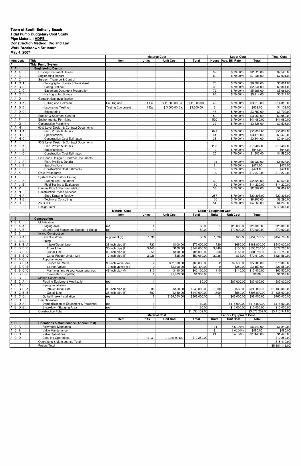
Town of South Bethany Beach
Tidal Pump Budgetary Cost Study
Pipe Material: HDPE
Construction Method: Dig and Lay
Work Breakdown Structure
Total Cost
WBS Code Title Item Units Unit Cost Total Hours Avg. Bill Rate Total
A Tidal Pump System
A A Engineering Design
A A A Existing Document Review 32 $ 79.00/hr $2,528.00 $2,528.00
A A B Engineering Report 89 $ 79.00/hr $7,031.00 $7,031.00
A A C Survey - Traverse & Control
A A C A - Topographic Survey & Worksheet 76 $ 79.00/hr $6,004.00 $6,004.00
A A C B - Boring Stakeout 36 $ 79.00/hr $2,844.00 $2,844.00
A A C C - Easement Document Preparation 72 $ 79.00/hr $5,688.00 $5,688.00
A A C D - Hydrographic Survey 66 $ 79.00/hr $5,214.00 $5,214.00
A A D
A A D A - Drilling and Fieldwork Drill Rig use 1 Ea. $ 11,000.00 Ea. $11,000.00 42 $ 79.00/hr $3,318.00 $14,318.00
A A D B - Laboratory Testing Testing Equipment 1 Ea. $ 3,500.00 Ea. $3,500.00 8 $ 79.00/hr $632.00 $4,132.00
A A D C - Engineering 48 $ 79.00/hr $3,792.00 $3,792.00
A A E 50 $ 79.00/hr $3,950.00 $3,950.00
A A F 520 $ 79.00/hr $41,080.00 $41,080.00
A A G 32 $ 79.00/hr $2,528.00 $2,528.00
A A H
A A H A - Plan, Profile & Details 641 $ 79.00/hr $50,639.00 $50,639.00
A A H B - Specifications 44 $ 79.00/hr $3,476.00 $3,476.00
A A H C - Construction Cost Estimates 36 $ 79.00/hr $2,844.00 $2,844.00
A A I
A A I A - Plan, Profile & Details 233 $ 79.00/hr $18,407.00 $18,407.00
A A I B - Specifications 12 $ 79.00/hr $948.00 $948.00
A A I C - Construction Cost Estimates 20 $ 79.00/hr $1,580.00 $1,580.00
A A J
A A J A - Plan, Profile & Details 113 $ 79.00/hr $8,927.00 $8,927.00
A A J B - Specifications 6 $ 79.00/hr $474.00 $474.00
A A J C - Construction Cost Estimates 6 $ 79.00/hr $474.00 $474.00
A A K 130 $ 79.00/hr $10,270.00 $10,270.00
A A L
A A L A - Procedures Document 32 $ 79.00/hr $2,528.00 $2,528.00
A A L B - Field Testing & Evaluation 180 $ 79.00/hr $14,220.00 $14,220.00
A A M Canvas Bids & Recommedation 33 $ 79.00/hr $2,607.00 $2,607.00
A A N Construction Phase Services
A A N A - Shop Drawing Review 257 $ 79.00/hr $20,303.00 $20,303.00
A A N B - Technical Consulting 105 $ 79.00/hr $8,295.00 $8,295.00A A O As-Builts 54 $ 79.00/hr $4,266.00 $4,266.00
Design Total $249,367.00
Material Cost Labor / Equipment Cost
Item Units Unit Cost Total Units Unit Cost Total
A B Construction
A B A Mobilization
A B A A Staging Area (ea) 1 $0.00 1 $25,000.00 $25,000.00 $25,000.00
A B A B Material and Equipment Transfer & Setup (ea) 1 $0.00 1 $70,000.00 $70,000.00 $70,000.00
A B B Inland Construction
A B B A Civil Site Work alignment (lf) 7,036 $0.00 7,036 $22.00 $154,792.00 $154,792.00
A B B B Piping
A B B B A Intake/Outfall Line 36-inch pipe (lf) 720 $100.00 $72,000.00 720 $650.00 $468,000.00 $540,000.00
A B B B B Trunk Line 36-inch pipe (lf) 3,440 $100.00 $344,000.00 3,440 $155.00 $533,200.00 $877,200.00
A B B B C Outfall Line 36-inch pipe (lf) 850 $100.00 $85,000.00 850 $155.00 $131,750.00 $216,750.00
A B B B D Canal Feeder Lines (12") 12-inch pipe (lf) 2,026 $25.00 $50,650.00 2,026 $35.00 $70,910.00 $121,560.00
A B B C Appurtanances
A B B C A 36-inch I/O Valve 36-inch valve (ea) 2 $32,500.00 $65,000.00 2 $2,500.00 $5,000.00 $70,000.00
A B B C B 12-inch Valves 12-inch valves (ea) 9 $2,600.00 $23,400.00 9 $350.00 $3,150.00 $26,550.00
A B B C C Manholes and Assoc. Appurtenances 48-inch dia (vf) 110 $410.00 $45,100.00 110 $140.00 $15,400.00 $60,500.00
A B B C D Flowmeter (Propeller) 1 $1,989.00 $1,989.00 1 $0.00 $1,989.00
A B C Marine Construction
A B C A Floating Equipment Mobilization (ea) 1 $0.00 1 $87,000.00 $87,000.00 $87,000.00
A B C B Piping Installation
A B C B A Intake/Outfall Line 36-inch pipe (lf) 1,600 $150.00 $240,000.00 1,600 $560.00 $896,000.00 $1,136,000.00
A B C B B Outfall Line 36-inch pipe (lf) 1,600 $150.00 $240,000.00 1,600 $560.00 $896,000.00 $1,136,000.00
A B C C Outfall/Intake Installation (ea) 2 $184,000.00 $368,000.00 2 $46,000.00 $92,000.00 $460,000.00
A B D Demobilization
A B D A Demobilization of Equipment & Personnel (ea) 1 $0.00 1 $115,000.00 $115,000.00 $115,000.00A B D B Breakdown Stagging Area (ea) 1 $0.00 1 $15,000.00 $15,000.00 $15,000.00
Construction Total $1,535,139.00 $3,578,202.00 $5,113,341.00
Item Units Unit Cost Total Units Unit Cost Total
A C Operations & Maintenance (Annual Cost)
A C A Flowmeter Monitoring 104 $ 60.00/hr $6,240.00 $6,240.00
A C B Valve Maintenance 8 $ 60.00/hr $480.00 $480.00
A C C Valve Operations 24 $ 60.00/hr $1,440.00 $1,440.00A C D Cleaning Operations 5 Ea. $ 2,050.00 Ea. $10,250.00 $10,250.00
Operations & Maintenance Total $18,410.00
Project Total $5,381,118.00
Material Cost Labor / Equipment Cost
90% Level Design & Contract Documents
Bid Ready Design & Contract Documents
O&M Procedures
System Confirmatory Testing
May 4, 2007
Geotechnical Investigation
Labor CostMaterial Cost
Erosion & Sediment Control
Environmental Permitting
Construction Permitting
60% Level Design & Contract Documents

PROJECT SCHEDULE
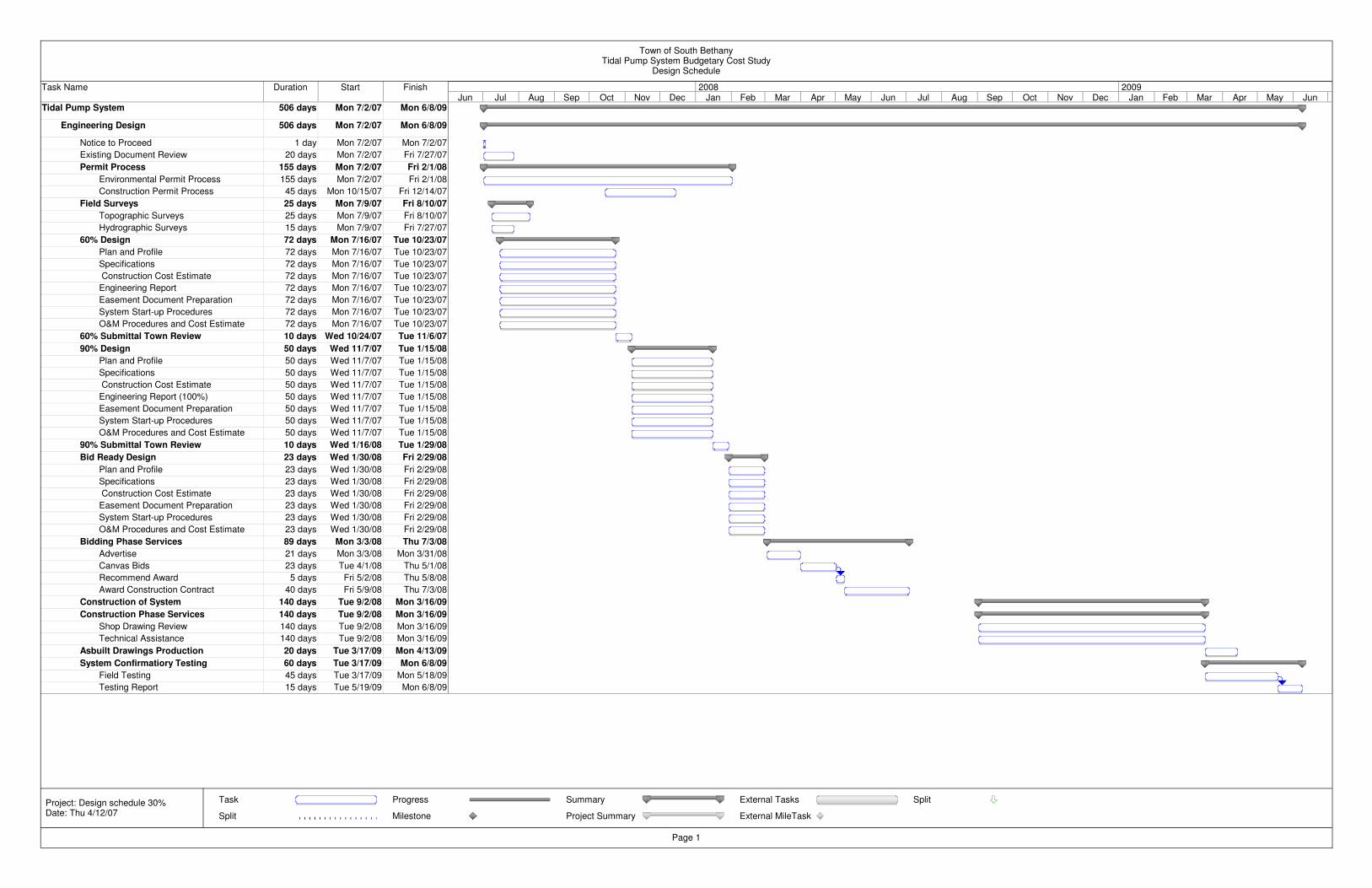
Task Name Duration Start Finish
Tidal Pump System 506 days Mon 7/2/07 Mon 6/8/09
Engineering Design 506 days Mon 7/2/07 Mon 6/8/09
Notice to Proceed 1 day Mon 7/2/07 Mon 7/2/07
Existing Document Review 20 days Mon 7/2/07 Fri 7/27/07
Permit Process 155 days Mon 7/2/07 Fri 2/1/08
Environmental Permit Process 155 days Mon 7/2/07 Fri 2/1/08
Construction Permit Process 45 days Mon 10/15/07 Fri 12/14/07
Field Surveys 25 days Mon 7/9/07 Fri 8/10/07
Topographic Surveys 25 days Mon 7/9/07 Fri 8/10/07
Hydrographic Surveys 15 days Mon 7/9/07 Fri 7/27/07
60% Design 72 days Mon 7/16/07 Tue 10/23/07
Plan and Profile 72 days Mon 7/16/07 Tue 10/23/07
Specifications 72 days Mon 7/16/07 Tue 10/23/07
Construction Cost Estimate 72 days Mon 7/16/07 Tue 10/23/07
Engineering Report 72 days Mon 7/16/07 Tue 10/23/07
Easement Document Preparation 72 days Mon 7/16/07 Tue 10/23/07
System Start-up Procedures 72 days Mon 7/16/07 Tue 10/23/07
O&M Procedures and Cost Estimate 72 days Mon 7/16/07 Tue 10/23/07
60% Submittal Town Review 10 days Wed 10/24/07 Tue 11/6/07
90% Design 50 days Wed 11/7/07 Tue 1/15/08
Plan and Profile 50 days Wed 11/7/07 Tue 1/15/08
Specifications 50 days Wed 11/7/07 Tue 1/15/08
Construction Cost Estimate 50 days Wed 11/7/07 Tue 1/15/08
Engineering Report (100%) 50 days Wed 11/7/07 Tue 1/15/08
Easement Document Preparation 50 days Wed 11/7/07 Tue 1/15/08
System Start-up Procedures 50 days Wed 11/7/07 Tue 1/15/08
O&M Procedures and Cost Estimate 50 days Wed 11/7/07 Tue 1/15/08
90% Submittal Town Review 10 days Wed 1/16/08 Tue 1/29/08
Bid Ready Design 23 days Wed 1/30/08 Fri 2/29/08
Plan and Profile 23 days Wed 1/30/08 Fri 2/29/08
Specifications 23 days Wed 1/30/08 Fri 2/29/08
Construction Cost Estimate 23 days Wed 1/30/08 Fri 2/29/08
Easement Document Preparation 23 days Wed 1/30/08 Fri 2/29/08
System Start-up Procedures 23 days Wed 1/30/08 Fri 2/29/08
O&M Procedures and Cost Estimate 23 days Wed 1/30/08 Fri 2/29/08
Bidding Phase Services 89 days Mon 3/3/08 Thu 7/3/08
Advertise 21 days Mon 3/3/08 Mon 3/31/08
Canvas Bids 23 days Tue 4/1/08 Thu 5/1/08
Recommend Award 5 days Fri 5/2/08 Thu 5/8/08
Award Construction Contract 40 days Fri 5/9/08 Thu 7/3/08
Construction of System 140 days Tue 9/2/08 Mon 3/16/09
Construction Phase Services 140 days Tue 9/2/08 Mon 3/16/09
Shop Drawing Review 140 days Tue 9/2/08 Mon 3/16/09
Technical Assistance 140 days Tue 9/2/08 Mon 3/16/09
Asbuilt Drawings Production 20 days Tue 3/17/09 Mon 4/13/09
System Confirmatiory Testing 60 days Tue 3/17/09 Mon 6/8/09
Field Testing 45 days Tue 3/17/09 Mon 5/18/09
Testing Report 15 days Tue 5/19/09 Mon 6/8/09
Jun Jul Aug Sep Oct Nov Dec Jan Feb Mar Apr May Jun Jul Aug Sep Oct Nov Dec Jan Feb Mar Apr May Jun2008 2009
Task
Split
Progress
Milestone
Summary
Project Summary
External Tasks
External MileTask
Split
Town of South BethanyTidal Pump System Budgetary Cost Study
Design Schedule
Page 1
Project: Design schedule 30%Date: Thu 4/12/07
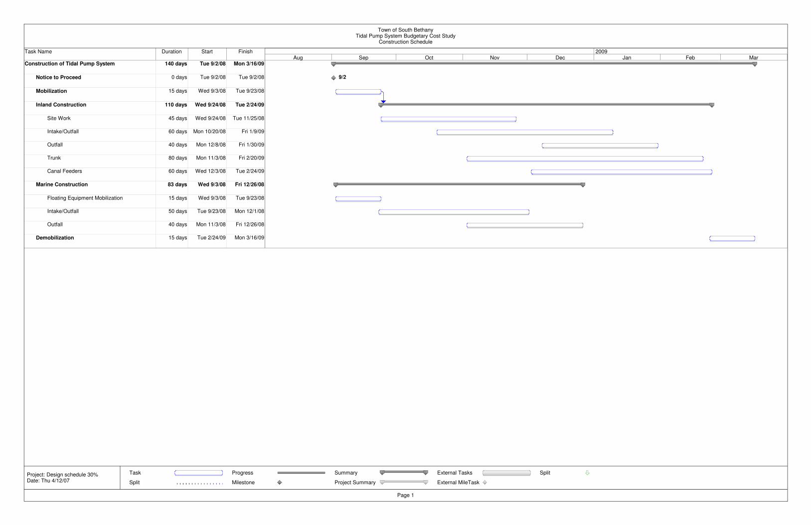
Task Name Duration Start Finish
Construction of Tidal Pump System 140 days Tue 9/2/08 Mon 3/16/09
Notice to Proceed 0 days Tue 9/2/08 Tue 9/2/08
Mobilization 15 days Wed 9/3/08 Tue 9/23/08
Inland Construction 110 days Wed 9/24/08 Tue 2/24/09
Site Work 45 days Wed 9/24/08 Tue 11/25/08
Intake/Outfall 60 days Mon 10/20/08 Fri 1/9/09
Outfall 40 days Mon 12/8/08 Fri 1/30/09
Trunk 80 days Mon 11/3/08 Fri 2/20/09
Canal Feeders 60 days Wed 12/3/08 Tue 2/24/09
Marine Construction 83 days Wed 9/3/08 Fri 12/26/08
Floating Equipment Mobilization 15 days Wed 9/3/08 Tue 9/23/08
Intake/Outfall 50 days Tue 9/23/08 Mon 12/1/08
Outfall 40 days Mon 11/3/08 Fri 12/26/08
Demobilization 15 days Tue 2/24/09 Mon 3/16/09
9/2
Aug Sep Oct Nov Dec Jan Feb Mar2009
Task
Split
Progress
Milestone
Summary
Project Summary
External Tasks
External MileTask
Split
Town of South BethanyTidal Pump System Budgetary Cost Study
Construction Schedule
Page 1
Project: Design schedule 30%Date: Thu 4/12/07

HYDRAULIC ANALYSIS
DATA SHEETS