Embed Size (px)
Citation preview
Page 1 of 162 Signature of the tenderer under seal of the firm
SOUTH EASTERN COALFIELDS LTD.
NOTICE INVITING TENDER NO: 47/OT/SECL-
JUNADIH/Balance P. Way/2014 Dated 28.10.2014.
Tender document for Balance work of Laying & Linking of
Railway track including supply of ballast & other P. Way
materials in connection with construction management and
arrangement of new Railway Siding for rapid loading system at
Junadih Siding of SECL at Gevra, Dist. Korba (C.G).
PART-1
TECHNICAL BID
CONTENTS
Section-1 : Notice Inviting Tender and Instructions to Tenderers
Section-2 : Tender and Contract Form
Section-3 : Special Conditions of Contract
Section-4 : Schedule A to F
Section-5: Technical Specifications
Section-6: Drawings, if any
PART- 2
FINANCIAL BID
SCHEDULE (BILL) OF QUANTITIES
Issued to (Name of Tenderer):________________________________________
Address of tenderer:_________________________________________________
Signature of officer issuing the documents___________________
Designation _______________________________
Date of Issue___________________
(A Govt. of India Enterprise)
Regional Project Office, KOLKATA
56 C R Avenue, 2nd floor, Kolkata – 700 012
e.mail : [email protected]
Phone No: (033) 22367118/7146/7162/7143(Fax)
Page 2 of 162 Signature of the tenderer under seal of the firm
RITES LTD (A Govt. of India Enterprise)
REGIONAL PROJECT OFFICE, 56, C.R. Ave. (2nd fl), Kolkata-12
Phone No. 033-2236 7118/46/62 FAX-033 2236 7143
NOTICE INVITING TENDER
NIT NO: 47/OT/SECL-JUNADIH/Balance P. Way/2014 Dt.28.10.2014.
GGM (P) RITES Ltd, Kolkata for & on behalf of South Eastern
Coalfields Ltd. (SECL) invites sealed tenders from contractors who
fulfill qualifying criteria stipulated in Tender Documents for the
following work:
Name of work: Balance work of Laying & Linking of Railway track
including supply of ballast & other P. Way materials at Junadih Siding
of SECL at Gevra, Dist. Korba (C.G). Estimated Cost:
Rs203.37 Lakh (Approx), EMD: Rs.2,03,500/-, Completion period: 08
(Eight) months. Sale of Tender Documents: From 31.10.2014. Last
date of Submission of Tender: 17.11.2014 up to 14.00 Hrs. Tender
documents can be purchased from the above address at a cost of
Rs.5,000/- in the form of DD/PO/BC drawn on any Schedule Bank in
favour of RITES Ltd., payable at Kolkata. For complete Tender
Documents including qualifying criteria etc. please visit:
(www.rites.com) or (www.tendervalue.in) or contact this office.
Addendum/corrigendum, if any, would be hoisted on the website only.
Page 3 of 162 Signature of the tenderer under seal of the firm
PART - 1
TECHNICAL BID
Section – 1
NOTICE INVITING TENDER &
INSTRUCTIONS TO TENDERERS
Page 4 of 162 Signature of the tenderer under seal of the firm
SECTION 1
NOTICE INVITING TENDER AND INSTRUCTIONS TO TENDERERS
Tender No. 47/OT/SECL-JUNADIH/Balance P. Way/2014 Dt. 28.10.2014
1.0 GENERAL
1.1 Tender Notice
Tenders are invited Single Packet system by RITES Ltd., a Public Sector Enterprise under
the Ministry of Railways, acting for and on behalf of South Eastern Coalfields Limited
(SECL) (Employer) as an Agent/Power of Attorney Holder, from working contractors
(including contractors who have executed works within the last five years reckoned from the
scheduled date of opening of tender) of Government Organizations/Semi Government
Organizations of Central or State Government; or Public Sector undertakings /Autonomous
Bodies of Central or State Government ; or Public Ltd., Companies listed in Stock Exchange
in India or Abroad for the work of Balance work of Laying & Linking of Railway track
including supply of ballast & other P. Way materials in connection with construction
management and arrangement of new Railway Siding for rapid loading system at Junadih
Siding of SECL at Gevra, Dist. Korba (C.G).
(Note : Throughout these bidding documents, the terms ‘bid’ and ‘tender’ and their
derivatives are synonymous).
1.2 Estimated Cost of Work
The work is estimated to cost Rs.2,03,37,222/- (Rupees two crore three lakh thirty seven
thousand two hundred twenty two only). This Estimate, however, is given merely as a rough
guide.
1.3 Time for Completion
The time allowed for completion will be 08 (Eight) months from the date of start which is
defined in Schedule F under Clause 5.1a of Clauses of Contract.
1.4 Brief Scope of Work
a) Earthwork in formation
b) Procurement of PSC Sleepers, Points & Crossings and P. Way Fittings
c) Procurement of track ballast
d) Thermit welding of Rail joint including supply of welding portion
e) Laying and linking of new Railway track and points & crossings
1.5 Availability of Site
The site for the work is available/ shall be made available in parts, as specified below:
The site for the work is available.
2.0 QUALIFICATION CRITERIA TO BE SATISFIED
2.1 The Qualification Criteria to be satisfied are given at Annexure I enclosed.
Page 5 of 162 Signature of the tenderer under seal of the firm
2.2 The Qualification Criteria to be satisfied will depend on the category of works,
whether Normal or Large. Normal Works are those costing upto Rs.100 Crores each
and Large Works are those costing more than Rs.100 Crores. The work for which
the Tender is being invited falls under the category of Normal .
2.3 The Qualification Criteria to be satisfied will also depend on whether the Work falls
in Normal area or Difficult area. Difficult area includes North East States, Jammu &
Kashmir, Jharkhand, Chattisgarh and Andaman & Nicobar Islands. Normal area
covers all areas other than Difficult area. The work for which this Tender has been
invited falls under Difficult area.
2.4 In this Tender Joint Venture is not allowed.
2.5 The documents to be furnished by the Bidder to prove that he is satisfying the
Qualification Criteria laid down should all be in the Bidder’s name, except in cases
where though the name has changed, the owners continued to remain the same and in
cases of amalgamation of entities.
3.0 FORMAT AND CHECK LIST FOR SUBMISSION OF INFORMATION ON
QUALIFICATION CRITERIA
3.1 Other than Joint Ventures
The Tenderer shall furnish a Letter of Transmittal as given in Annexure II A
enclosing the documents mentioned therein/listed in para 1(a) of Annexure IA.
3.2 Joint Ventures (For Large Works) (Not Applicable)
The Partner in charge / Lead member shall furnish a Letter of Transmittal as given in
Annexure II B (L) enclosing the documents mentioned therein/listed in para 1(b) of
Annexure I A.
3.3 Joint ventures (For Normal Works) (Not Applicable)
The Partner in charge / Lead Member shall furnish a Letter of Transmittal as given in
Anneuxre II B (N) enclosing the documents mentioned therein/listed in para 1(c) of
Annexure I A.
4.0 CONTENTS OF TENDER DOCUMENT
4.1 Each set of Tender or Bidding Document will comprise the Documents listed below
and addenda issued in accordance with para 7 :
PART – 1 :- Technical Bid Packet (Read with Correction Slip Nos.1 to 13)
Section 1 Notice Inviting Tender and Instructions to Tenderers.
Section 2 Tender and Contract Form.
Section 3 Special Conditions.
Section 4 Schedules A to F
Section 5 Technical Specifications
Section 6 Drawings
Page 6 of 162 Signature of the tenderer under seal of the firm
PART – 2 :- Financial Bid Packet
Schedule of Quantities (Bill of Quantities)
PART – 3:- General Conditions of Contract (Read with correction Slip Nos. 1 to 6)
Section 7 Conditions of Contract
Section 8 Clauses of Contract
Section 9 RITES Safety Code
Section 10 RITES Model Rules for protection of Health and Sanitary
arrangements for Workers
Section 11 RITES Contractor’s Labour Regulations
4.2 General Conditions of Contract (Compilation of Sections 7 to 11) with upto date
correction slips is also available in RITES website <www.rites.com>
5.0 ISSUE OF TENDER DOCUMENT
5.1 A complete set of Tender Document (Technical and Financial Bid) described in Para
4.1 above can be seen in the office of the Group General Manager (Projects), RITES
Ltd., 56, C.R. Avenue, 2nd
Floor, Kolkata – 700 012 between hours of 11.00 AM and
4.00 PM every day except on Saturdays, Sundays and Public Holidays.
5.2 One set of Tender Document may be purchased from the office of the Group General
Manager (Projects), RITES Ltd., 56, C.R. Avenue, 2nd
Floor, Kolkata – 700 012 from
31.10.2014 to 14.11.2014 for a non refundable fee per set of Rs. 5,000/- (Rupees five
thousand only) in the form of Demand Draft/ Pay Order/ Banker’s cheque drawn on
any Scheduled Bank payable at Kolkata in favour of RITES Ltd., on submission of
an application. Tender document may be issued free of cost to such applicants as are
exempted from payment of cost of tender document as a matter of Government
Policy.
5.3 Tender Documents including drawings can also be downloaded from RITES Website
(www.rites.com) or (www.tendervalue.in) and in such a case, the Tenderer shall
deposit the cost of tender documents (unless he is exempted from such payment as a
matter of Government Policy) along with submission of tender, failing which his
tender shall not be opened. The cost of tender documents shall be deposited in the
form of a separate Banker’s cheque / Demand Draft / Pay Order and enclosed in the
envelope containing the Earnest Money Deposit. In case the Tenderer is exempted
from such payment, the onus of proving such exemption shall rest with the tenderer
and proof of the same shall be placed in the envelope meant for Earnest Money. The
amendments / clarifications to the Tender documents will also be available on the
above website.
5.4 Tender Documents downloaded from RITES website shall be considered valid for
participating in the tender process. During the scrutiny of downloaded tender
document, if any modification / correction etc. is noticed as compared to the original
documents posted on the website, the bid submitted by such a Tenderer is liable to be
rejected. In case the bid of a Tenderer who has downloaded the document from
Page 7 of 162 Signature of the tenderer under seal of the firm
website is accepted the contract shall be executed in the original / manual tender
document issued by the concerned RITES officer.
5.5 Clarifications on Tender Documents
A prospective Tenderer requiring any clarification on the Tender Document may
notify Sri K. Halder, Jt. General Manager (Civil), RITES Ltd., 56, C.R. Avenue, 2nd
Floor, Kolkata 700 012 in writing or by telefax/ or by E-mail at the following Postal
Address/ Fax No. (033) 2367143 or E-mail address: [email protected].
In cases where Pre-Bid Meeting is not proposed to be held, request for clarifications
including request for Extension of Time for submission of Bid, if any, must be
received not later than 10 (ten) days prior to the deadline for submission of tenders.
Details of such questions raised and clarifications furnished will be uploaded in
RITES website without identifying the names of the Bidders who had raised the
questions. Any modification of the Tender Document arising out of such
clarifications will also be uploaded on RITES website only.
In cases where Pre-Bid Meeting is proposed to be held, provisions in para 6.0 below
may be referred to.
6.0 PRE-BID MEETING: Not Applicable
7.0 AMENDMENT OF TENDER DOCUMENT
7.1 Before the deadline for submission of tenders, the Tender Document may be modified
by RITES Ltd. by issue of addenda/corrigendum. Issue of addenda / corrigenda will
however be stopped 7 days prior to the deadline for submission of tenders as finally
stipulated.
7.2 Addendum/corrigendum, if any, will be hosted on website only and shall become a
part of the tender document. All Tenderers are advised to see the website for
addendum/ corrigendum to the tender document which may be uploaded upto 7 days
prior to the deadline for submission of Tender as finally stipulated.
7.3 To give prospective Tenderers reasonable time in which to take the addenda/
corrigenda into account in preparing their tenders, extension of the deadline for
submission of tenders may be given as considered necessary by RITES.
8.0 TENDER VALIDITY
8.1 The Tender shall be valid for a period of 90 days from the due date for submission of
Tender or any extended date as indicated in sub para below.
8.2 In exceptional circumstances, during the process of evaluation of tenders and prior to
the expiry of the original time limit for Tender Validity, the Employer may request
that the Tenderers may extend the period of validity for a specified additional period.
The request and the tenderer’s response shall be made in writing. A Tenderer may
refuse the request without forfeiting his Earnest Money. A Tenderer agreeing to the
request will not be permitted to modify his Financial Bid to a higher amount but will
Page 8 of 162 Signature of the tenderer under seal of the firm
be required to extend the validity of the Earnest Money for the period of the
extension.
9.0 EARNEST MONEY
9.1 The Tender should be accompanied by Earnest Money of Rs.2,03,500/- (Rupees two
lakh three thousand five hundred only) in any of the forms given below:-
Banker’s Cheque / Pay Order/ Demand Draft payable at Kolkata, drawn in favour of
RITES Ltd.
9.2 Any Tender not accompanied by Earnest Money in an acceptable form shall be
rejected by the Employer as non-responsive unless the tenderer is exempted from
payment of Earnest Money as a matter of Government Policy. The onus of proving
such exemption shall rest with the Tenderer and such proof shall be placed in the
envelope meant for Earnest Money.
9.3 Refund of Earnest Money
a) Two Packet System: Not Applicable
The Earnest Money of the Tenderers whose Technical Bid is found not acceptable
will be returned without interest soon after scrutiny of Technical Bid has been
completed by the Employer subject to provisions of Para 9.4 (b). The Earnest Money
of the Tenderers whose Technical Bid is found acceptable but Financial Bid is
rejected will be returned without interest within 28 days of the end of Tender Validity
Period subject to provisions of Para 9.4 (b).
b) Single Packet System
After evaluation of the Financial Bids, the Earnest Money of unsuccessful Tenderers
will be returned without interest within 28 days of the end of Tender Validity Period
subject to provisions of Para 9.4 (b).
c) The Earnest Money shall be refunded only through Electronic Fund Transfer. The
tenderer shall submit RTGS/NEFT Mandate Form as per proforma given in Annexure
IX, duly filled in.
d) In case of both Two Packet and Single Packet System, the Earnest Money of the
successful Tenderer, without any interest, will be adjusted as a part of the Security
Deposit payable in terms of provisions in the General Conditions of Contract (Clause
1A of Clauses of Contract).
9.4 The Earnest Money is liable to be forfeited
a) if after bid opening, but before expiry of bid validity or issue of Letter of
Acceptance, whichever is earlier, any Tenderer
i) withdraws his tender or
Page 9 of 162 Signature of the tenderer under seal of the firm
ii) makes any modification in the terms and conditions of the tender
which are not acceptable to the Employer.
b) in case any statement/information/document furnished by the Tenderer is
found to be incorrect or false.
c) in the case of a successful Tenderer, if the Tenderer
i) fails to furnish the Performance Guarantee within the period specified
under Clause 1 of “Clauses of Contract”. or
ii) fails to commence the work without valid reasons within the period as
specified in Schedule F after the date of issue of Letter of Acceptance
or from the first date of handing over of the site, whichever is later.
In case of forfeiture of E.M. as prescribed hereinabove, the Tenderer shall not be
allowed to participate in the retendering process of the work.
10.0 ALTERNATIVE PROPOSALS BY THE TENDERERS
The Tenderers shall submit offers which comply strictly with the requirements of the
Tender Document as amended from time to time as indicated in Para 7.0 above.
Alternatives or any modifications shall render the Tender invalid.
11.0 SUBMISSION OF TENDER
11.1 Two Packet System and Single Packet System
(a) Two Packet System : Not Applicable
The tenderer shall submit the Tender in original in two packets as under:-
PACKET A :- TECHNICAL BID
Envelope 1 Earnest Money alongwith Mandate Form as per
Annexure-IX duly filled in & Cost of Tender Document
if the bid is submitted on the document downloaded
from RITES website, unless exempted from both
payments as a matter of Government Policy. If
exempted, the document, the documents substantiating
such exception must be placed in this envelope.
Envelope 2 “Authority to Sign”, ‘Integrity Pact’ (when applicable)
and Qualification Information along with all enclosures
/ documents as per Letter of Transmittal/ Checklist
given in Annexure II A/ II B (L)/IIB(N). As regards
“Authority to Sign” Para 11.2 below may be referred to.
As regards ‘Integrity Pact’, para 11.7 below may be
referred to.
Page 10 of 162 Signature of the tenderer under seal of the firm
Technical Bid (Part 1 and Part 3) (Refer Para 4.1)
including
signature on Tender Form (Section 2) duly witnessed
after filling up blanks therein.
Each page of the above documents including all
Drawings should bear the dated initials of the Tenderer
along with the seal of the Company, in token of
confirmation of having understood the Contents.
PACKET B :- FINANCIAL BID
Envelope 3 Schedule/Bill of Quantities.
Each page of the Financial Bid (Part 2 – Refer Para 4.1) should be signed by the
Tenderer along with the seal of the company. In the last page of Financial Bid, at the
end, the Tenderer should sign in full with the name of the Company, Seal of the
Company and Date.
All rates and amounts, whether in figures and words, must be written in indelible ink.
Each Correction, Cutting, Addition and overwriting should be initialed by the
Tenderer.
The rates must be quoted in decimal coinage. Amounts must be quoted in full rupees
by ignoring fifty paise and less and considering more than fifty paise as rupee one. If
the same item figures in more than one section/part of Schedule of Quantities, the
Tenderer should quote the same rate for that item in all sections/parts. If different
rates are quoted for the same item, the least of the different rates quoted only shall be
considered for evaluation of that item in all sections/parts of the Schedule of
Quantities.
Instructions contained in subsequent Para 17.6 (a) on “Item rate tender” and 17.6 (b)
on “Percentage rate tender” may be carefully studied and complied with.
b) Single Packet System : Both Technical Bid (including signature on Tender Form in
Section 2 duly witnessed) and Financial Bid Documents will be submitted in one
Packet. Precautions as described above for Two Packet System shall be observed by
the tenderers.
11.2 Authority to Sign
a) If the applicant is an individual, he should sign above his full type written
name and current address.
b) If the applicant is a proprietary firm, the Proprietor should sign above his full
type written name and the full name of his firm with its current address.
c) If the applicant is a firm in partnership, the Documents should be signed by all
the partners of the firm above their full type written names and current
addresses. Alternatively the Documents should be signed by the person
holding Power of Attorney for the firm in the Format at Annexure IV.
Page 11 of 162 Signature of the tenderer under seal of the firm
d) If the applicant is a limited Company, or a Corporation, the Documents shall
be signed by a duly authorized person holding Power of Attorney for signing
the Documents in the Format at Annexure IV.
e) If the applicant is a Joint Venture, the Documents shall be signed by the Lead
Member holding Power of Attorney for signing the Document in the Format at
Annexure V. The signatory on behalf of such Lead Partner shall be the one
holding the Power of Attorney in the Format at Annexure IV.
11.3 Items to be kept in mind while furnishing details
While filling in Qualification Information documents and the Financial Bid, following
should be kept in mind:
i) There shall be no additions or alterations except those to comply with the
instructions issued by the Employer or as necessary to correct errors, if any,
made by the Tenderers.
ii) Conditional Offer/ Tender will be rejected. Unconditional rebate/ discounts in
the Financial offer will however be accepted.
iii) The Employer reserves the right to accept or reject any conditional
rebate/discounts. While evaluating the Bid Price, the conditional
rebates/discounts which are in excess of the requirements of the bidding
documents or otherwise result in accrual of unsolicited benefits to the
Employer, shall not be taken into account.
11.4 Sealing and Marking of Tenders
11.4.1 Two Packet System : Not Applicable
(a) PACKET A – TECHNICAL BID
Envelopes 1 & 2 as described in Para 11.1 (a) above should be sealed separately
superscribing “Technical Bid” with Envelope Number, Name of the work and
Name of the tenderer. In addition, the following should also be superscribed on the
respective envelopes.
Envelope 1 i) Earnest Money alongwith Mandate Form as per
Annexure – IX.
ii) Cost of Tender Document if the Bid is
submitted on the document downloaded from
RITES website.
iii) If the Bidder is exempted from payment
Earnest Money and Cost of Tender Document,
he should superscribe “Documents
Substantiating Exemption from Payment of
Earnest Money and Cost of Tender Documents’.
Page 12 of 162 Signature of the tenderer under seal of the firm
Envelope 2 i) Authority to Sign, ‘Integrity Pact’ (when
applicable as per para 11.7 below) and
Qualification Information/ documents as per
checklist in Annexure IIA / IIB(L)/ II B (N).
ii) Technical Bid including Drawings
Both the envelopes should be put in a packet which should be sealed. The following
should be superscribed on the packet:
i) Packet A – Technical Bid
ii) Name of the Work
iii) Name of the Tenderer
(b) PACKET B – FINANCIAL BID
Envelope 3 – Financial Bid should be put in Packet B which should be sealed. The
following should be superscribed on the packet.
i) Packet B - Financial Bid
ii) Name of the work
iii) Name of the tenderer
(c) Both packets A and B should be put inside an outer envelope and sealed. This
envelope should be superscribed with the following details:
i) Tender for (Name of work)
ii) Tender number
iii) Date and time of opening of Tender
iv) From (Name of Tenderer)
v) Addressed to ---- (RITES Officer inviting the Tender)
11.4.2 Single Packet System
Two envelopes of Technical Bid and one of Financial Bid shall be made out as
stipulated in Para 11.4.1 (a) and (b) above with the Name of the work and Name of
the Tenderer superscribed on each of the envelopes. All the three envelopes shall be
put in a Single Packet which shall be superscribed in the same manner as given in
Para 11.4.1 (c) above.
11.4.3 If the envelopes and packets are not superscribed and sealed as indicated in Paras
11.4.1/ 11.4.2 above, the Employer will assume no responsibility for the
misplacement or premature opening of the Tender.
11.5 Deadline for submission of Tender
11.5.1 Tenders must be received by the Employer at the following address not later than
14.00 Hrs. on 17.11.2014. In the event of the specified date for the submission of the
Tender being declared a holiday due to Strike/Bandh or on any account by the
Employer, the Tenders will be received up to the appointed time on the next working
day.
Page 13 of 162 Signature of the tenderer under seal of the firm
Address for submission of Tender: At Office of the Group General Manager
(Projects), RITES Ltd., 56, C.R. Avenue, 2nd
Floor, Kolkata – 700 012.
11.5.2 The Employer may extend the deadline for submission of Tenders by issuing an
amendment in writing in accordance with Para 7.3 in which case all rights and
obligations of the Employer and the Tenderer previously subject to the original
deadline will be subject to new deadline.
11.6 Late Tender / Delayed Tender
Any Tender received by the Employer after the specified date and time of receipt of
Tender will be returned unopened to the Tenderer.
11.7 Integrity Pact
(i) The Bidder/Contractor is required to enter into an Integrity Pact with the
Employer, in the Format at Annexure VIII. The Integrity Pact enclosed as
Annexure VIII will be signed by RITES for and on behalf of Employer as its
Agent/Power of Attorney Holder at the time of execution of Agreement with
the successful Bidder. While submitting the Bid, the Integrity Pact shall be
signed by the duly authorized signatory of the Bidder/Lead Member of JV. In
case of failure to submit the Integrity Pact duly signed and witnessed, along
with the Bid, the Bid is likely to be rejected.
(ii) In case of any contradiction between the Terms and Conditions of the Bid
Document and the Integrity Pact, the former will prevail.
Provided always that provision of this para 11.7 – Integrity Pact, shall be
applicable only when so provided in para 11.7A below which will also
stipulate the name and address of the Independent External Monitor as well as
the Name, designation and address of the official nominated by the Employer
to act as the Liaison Officer between the Independent External Monitor and
the Engineer-in-Charge as well as the Contractor.
11.7A Whether para 11.7 (Integrity Pact) shall be applicable YES
Name, Designation and Address of RITES’ Liaison
Officer: Sri Y.K. Sharma,
Group General Manager/Airport,
RITES Ltd., Gurgaon.
11.8 Modification and Withdrawal of Bids
11.8.1 Tenderers may modify or withdraw their bids by giving notice in writing before the
deadline prescribed in para 11.5 for submission of Bids.
11.8.2 Each modification or withdrawal notice shall be prepared, sealed, marked and
delivered in accordance with paras 11.1, 11.2 and 11.4 with the outer envelopes
additionally marked ‘Modification’ or ‘Withdrawal’ as appropriate.
Page 14 of 162 Signature of the tenderer under seal of the firm
The envelopes for modifications on ‘Technical Bid’ and ‘Financial Bid’ shall be
submitted in separate sealed envelopes and marked as ‘Modifications of Technical
Bid’ or ‘Modifications of Financial Bid’ as the case may be.
11.8.3 No bid may be modified after the deadline for submission of Bids except as indicated
below. If a Bidder makes a suo moto offer of rebate / discount in his Financial Bid
after the deadline for submission of Bids, such offer will not be considered for
Financial evaluation of Tenders. But if the Tenderer is successful in the Bid based on
his original offer without considering the suo moto offer, the rebate / discount offered
will be taken into account for incorporation in the Contract Agreement.
11.8.4 Withdrawal or modification of a Bid, subject to provisions in Para 11.8.3 above, after
the deadline for submission of Bids shall result in forfeiture of the Earnest Money.
12.0 TENDER OPENING, EVALUATION AND CLARIFICATIONS OF
APPLICATIONS
12.1 The Employer will open all the Tenders received (except those received late or
delayed)as described in para 12.2/12.3 below, in the presence of the Tenderers or their
representatives who choose to attend at 14.30 Hrs. on 17.11.2014 in the office of the
Group General Manager (Projects), RITES Ltd., 56, C.R. Avenue, 2nd
Floor, Kolkata
– 700 012. In the event of the specified date of the opening being declared a holiday
by the Employer, the Tenders will be opened at the appointed time and location on the
next working day.
12.2 Two Packet System
(a) (i) The PACKET A will be opened and Envelope 1 containing Earnest Money and
Cost of Tender Document (where Bid is submitted in the document downloaded
from RITES website) of all the Tenderers will be opened first and checked. If the
Earnest Money furnished is not for the stipulated amount or is not in an
acceptable form (unless exempted) and where applicable, the cost of Tender
Document has not been enclosed for the correct amount and in an acceptable form
(unless exempted), the Envelope 2 of PACKET A (TECHNICAL BID) and
PACKET B will be returned to the Tenderer concerned unopened at the time of
opening of the Tender itself. The Envelopes 2 of PACKET A (TECHNICAL
BID) of other Tenderers who have furnished Earnest Money of correct amount in
acceptable form (unless exempted) and where applicable the cost of Tender
Document for the correct amount and in an acceptable form (unless exempted)
will then be opened. The Tenderer’s name, the presence of Earnest Money and
Authority to sign and such other details as the Employer may consider appropriate
will be announced by the Employer at the time of opening of Packet A. PACKET
B (FINANCIAL BID) of the Tenderers whose Technical Bids have been accepted
for evaluation will be checked to see if the seals are intact. All such PACKETS B
will be put in an envelope and sealed. The Employer’s official opening the
Tender will sign on this envelope and will also take the signatures of preferably
atleast two Tenderers or their representatives present. This envelope will be kept
in safe custody by the Employer.
Page 15 of 162 Signature of the tenderer under seal of the firm
(b) The Employer will scrutinise the Technical Bids accepted for evaluation to determine
whether each Tenderer
(i) has submitted `Authority to sign’ as per para 11.2 above and Integrity Pact
(where applicable) duly signed and witnessed as per para 11.7 above;
(ii) meets the Qualification Criteria stipulated in Para 2.0; and
(iii) conforms to all terms, conditions and specifications of the Tender Document
without any modifications or conditions.
(c) If required, the Employer may ask any such Tenderer for clarifications on his
Technical Bid. The request for clarification and the response from the Tenderer will
be in writing. If a Tenderer does not submit the clarification/document requested, by
the date and time set in the Employer’s request for clarification, the bid of such
Tenderer is likely to be rejected. Tenderers whose Technical Bids are not found
acceptable will be advised of the same and their Earnest Money and PACKET B
(FINANCIAL BID) will be returned unopened. Tenderers whose Technical Bids are
found acceptable will be advised accordingly and will also be intimated in writing of
the time and date and place where and when the PACKET B (Financial Bid) will be
opened.
(d) At the appointed place, time and date, in the presence of the Tenderers or their
representatives who choose to be present, the Employer will open the envelopes
containing the PACKET B (FINANCIAL BID). The Tenderer’s name, the tender
amount quoted and such other details as the Employer may consider appropriate will
be announced by the Employer.
12.3 Single Packet System
(a) Envelope 1 of all the Tenders will be opened first and checked. If the Earnest Money
furnished is not for the stipulated amount or is not in an acceptable form (unless
exempted) and where applicable the Cost of Tender Document has not been furnished
for the correct amount and in an acceptable form (unless exempted), the remaining
envelopes will be returned to the tenderer concerned unopened at the time of opening
of the Tender itself. The Envelopes no. 2 of Technical Bid and no. 3 of Financial Bid
of other Tenderers who have furnished Earnest Money and where applicable the Cost
of Tender Document, in acceptable form (unless exempted) will then be opened. The
Tenderer’s name, the presence of Earnest Money, the Authority to Sign the Tender,
amount quoted and such other details as the Employer may consider appropriate will
be announced by the Employer.
13.0 INSPECTION OF SITE BY THE TENDERERS
Tenderers are advised to inspect and examine the site and its surroundings and satisfy
themselves before submitting their Tenders, as to the nature of the ground and sub-
soil (as far as is practicable), the form and nature of the site, the means of access to
the site, the accommodation they may require and in general shall themselves obtain
all necessary information as to risks, contingencies and other circumstances which
may influence or affect their Tender. A Tenderer shall be deemed to have full
knowledge of the site whether he inspects it or not and no extra charges consequent
on any misunderstanding or otherwise shall be allowed. The Tenderer shall be
Page 16 of 162 Signature of the tenderer under seal of the firm
responsible for arranging and maintaining at his own cost all materials, tools & plants,
water, electricity, access, facilities for workers and all other services required for
executing the work unless otherwise specifically provided for in the contract
documents. Submission of a tender by a Tenderer implies that he has read this notice
and all other contract documents and has made himself aware of the scope and
specifications of the work to be done and of conditions and rates at which stores, tools
and plant etc. will be issued to him by the Employer and local conditions and other
factors having a bearing on the execution of the work.
14.0 EMPLOYER’S RIGHT ON ACCEPTANCE OF ANY TENDER
(i) If required, the Employer may ask any Tenderer the breakdown of unit rates. If
the Tenderer does not submit the clarification by the date and time set in the
Employers request for clarification, such Tender is likely to be rejected.
(ii) The competent authority on behalf of the Employer does not bind himself to
accept the lowest or any other Tender and reserves to himself the authority to
reject any or all the Tenders received without the assignment of any reason. All
Tenders in which any of the prescribed conditions is not fulfilled or any condition
is put forth by the Tenderer shall be summarily rejected.
15.0 CANVASSING PROHIBITED
Canvassing whether directly or indirectly, in connection with tenders is strictly
prohibited and the tenders submitted by the Contractors who resort to canvassing will
be liable to rejection.
16.0 EMPLOYER’s RIGHT TO ACCEPT WHOLE OR PART OF THE TENDER
The competent authority on behalf of the Employer reserves to himself the right of
accepting the whole or any part of the tender and the Tenderer shall be bound to
perform the same at the rates quoted.
17.0 MISCELLANEOUS RULES AND DIRECTIONS
17.1 The Tenderer shall not be permitted to tender for works if his near relative is posted
as Associated Finance Officer between the grades of AGM(F) and J.M (F) in the
concerned
SBU Unit of RITES or as an officer in any capacity between the grades of GGM/GM
and Engineer (both inclusive) of the concerned SBU of the Employer. He shall also
intimate the names of persons who are working with him in any capacity or are
subsequently employed by him and who are near relatives to any Gazetted officer in
the organization of the Employer. Any breach of this condition by the Tenderer would
render his Tender to be rejected.
No Engineer of Gazetted rank or other Gazetted Officer employed in Engineering or
Administrative duties in an Engineering Department of the Organisation of the
Employer is allowed to work as a contractor for a period of one year after his
retirement from the Employer’s service without the previous permission of the
Employer in writing. The contract is liable to be cancelled if either the Contractor or
any of his employees is found any time to be such a person who had not obtained the
Page 17 of 162 Signature of the tenderer under seal of the firm
permission of the Employer as aforesaid before submission of the tender or
engagement in the Contractor’s service.
17.2 If required by the Employer, the Tenderers shall sign a declaration under the officials
Secret Act 1923, for maintaining secrecy of the tender documents drawings or other
records connected with the work given to them. The unsuccessful Tenderers shall
return all the drawings given to them.
17.3 Use of correcting fluid anywhere in tender document is not permitted. Such tender is
liable for rejection.
17.4 a) In the case of Item Rate Tenders, only rates quoted shall be considered. Any tender
containing percentage below/above the rates quoted is liable to be rejected. Rates
quoted by the Tenderer in item rate tender in figures and words shall be accurately
filled in so that there is no discrepancy in the rates written in figures and words.
However, if a discrepancy is found, the rates which correspond with the amount
worked out by the Tenderer shall unless otherwise proved be taken as correct. If the
amount of an item is not worked out by the Tenderer or it does not correspond with
the rates written either in figures or in words then the rates quoted by the Tenderer in
words shall be taken as correct. Where the rates quoted by the Tenderer in figures
and in words tally but the amount is not worked out correctly, the rates quoted by the
Tenderer will, unless otherwise provided, be taken as correct and not the amount. In
the event that no rate has been quoted for any item(s), leaving space both in figure (s)
or word(s) and the amount blank, it will be presumed that the Tenderer has included
the cost of this/ these item (s) in other items and rate for such item (s) will be
considered as zero and work will be required to be executed accordingly.
b) In case of percentage Rate Tender only percentage quoted shall be considered. Any
tender containing item rates is liable to be rejected. Percentage quoted by the
Tenderer in percentage rate tender shall be accurately filled in figures and words so
that there is no discrepancy. If, for any Schedule in Financial Bid, the total amount
has been indicated by the Tenderer and if discrepancy is noticed in the percentages
quoted in words and figures, then the percentage which corresponds with the total
amount, shall, unless otherwise proved be taken as correct. If the total amount is not
worked out or if worked out, it does not correspond with the percentages written
either in figures or in words, then the percentage quoted by Tenderer in words shall be
taken as correct. When the percentages quoted by the Tenderer in figures and in
words tally but the total amount is not worked out correctly, the percentage quoted by
the Tenderes shall be taken as correct, unless proved otherwise and the total amount
worked out accordingly.
17.5 In the case of any Item rate tender where unit rate of any item/items appears
unrealistic, such tender will be considered as unbalanced and in case the Tenderer is
unable to provide satisfactory explanation, such a tender is liable to be disqualified
and rejected.
17.6 (a) In Item rate Tender, all rates shall be quoted on the tender form. The amount for
each item should be worked out and requisite totals given. Special care should be
taken to write the rates in figures as well as in words and the amount in figures only,
in such a way that interpolation is not possible. The total amount in each Schedule
should be written both in figures and in words. In case of figures, the word ‘Rs.’
should be written before the figure of rupees and word ‘P’ after the decimal figures,
e.g. Rs.2.15 P and in case of words, the word, ‘Rupees’ should precede and the word
Page 18 of 162 Signature of the tenderer under seal of the firm
‘Paise’ should be written at the end. Unless the rate is in whole rupees and followed
by the word ‘only’ it should invariably be up to two decimal places. While quoting the
rate in schedule of quantities, the word ‘only’ should be written closely following the
amount and it should not be written in the next line.
(b) In Percentage Rate Tender, the Tenderer shall quote percentage below / above (in
figures as well as in words) at which he will be willing to execute the work. He shall
also work out the total amount of his offer and the same should be written in figures
as well as in words in such a way that no interpolation is possible. In case of figures,
the word “Rs” should be written before the figure rupees and word ‘P’ after the
decimal figures (eg.) Rs.2.15 P and in case of words the word “Rupees” should
precede and the word “Paisa” should be written at the end.
17.7 Sales-tax/VAT (except Service Tax), purchase tax, turnover tax or any other tax/ Cess
on material, labour and Works in respect of this Contract shall be payable by the
Contractor and the Employer will not entertain any claim whatsoever in respect of the
same. However, in respect of Service Tax, same shall be paid by the Contractor to the
concerned department on demand and it will be reimbursed to him by the Engineer-
in-Charge after satisfying that it has been actually and genuinely paid by the
Contractor.
17.8 Each Bidder shall submit only one Bid either as an individual or as a Proprietor in a
Proprietary firm or as a Partner in a Partnership firm or as a Director of a limited
Company/Corporation or as a Partner in a Joint Venture. Any Bidder who has
submitted a Bid for a work, shall not be a witness for any other Bidder for the same
work. Failure to observe the above stipulations would render all such Tenders
submitted as a Bidder and / or as a witness, liable to summary rejection.
17.9 The Contractor shall be fully responsible for all matters arising out of the
Performance of the Contract and shall, at his own expense, comply with all laws/ acts/
enactments/ orders/ regulations/ obligations whatsoever of the Government of India,
State Government, Local Body and any Statutory Authority.
18.0 SIGNING OF CONTRACT AGREEMENT
18.1 The Tenderer whose tender has been accepted will be notified of the award by the
Employer by issue of a `Letter of Acceptance’ ‘ prior to expiration of the Bid Validity
period, in the form at Annexure VI.
The Letter of Acceptance will be sent to the Contractor in two copies one of which he
should return promptly, duly signed and stamped. The Letter of Acceptance will be a
binding Contract between the Employer and the Contractor till the formal Contract
Agreement is executed.
18.2 Within the period as specified in Clause 1 of `Clause of Contract’, of the date of issue
of Letter of Acceptance, the successful Tenderer shall deliver to the Employer,
Performance Guarantee and Additional Performance Guarantee (where applicable) in
the format prescribed.
Page 19 of 162 Signature of the tenderer under seal of the firm
18.3 The Tenderer whose Tender is accepted shall be required to submit at his cost stamp
papers of appropriate value as per the provisions of Indian Stamp Act within 15 days
of the date of issue of Letter of Acceptance.
18.4 At the same time the Employer notifies the successful Tenderer that his Tender has
been accepted, the Employer will direct him to attend the Employer’s office within 28
days of issue of Letter of Acceptance for signing the Agreement in the proforma at
Annexure VII. The Agreement will however be signed only after the Contractor
furnishes Performance Guarantee and Additional Performance Guarantee (where
applicable) and hence, where justified, the period of 28 days stipulated above will be
extended suitably.
Page 20 of 162 Signature of the tenderer under seal of the firm
ANNEXURE – I
QUALIFYING CRITERIA FOR WORKS CONTRACTS
1. Annual Financial Turnover
The bidder should have achieved a minimum annual financial turnover of Rs.203.37
Lakh in any one of the last 3 Financial Years.
Notes :
� The financial turnover will be taken as given under the head “Income” in audited
Profit and Loss Account and excluding non-recurring income, income from other
sources and stock. It is clarified that the Financial Turnover means relevant revenue as
recorded in the Income side of Profit and Loss Account. It does not mean Profit.
� Closing stocks in whatsoever manner should not form part of turnover.
� Weightage of 7% (compounded annually) shall be given for equating the financial
turnover of the previous years to the current year.
� For considering the Financial Years, for example for a work for which the Tender is
being opened in Financial Year 2014-15, the last three Financial Years will be 2013-
14, 2012-13 and 2011-12. For a Tender opened on (say) 05.09.2014 (FY 2014-15),
with weightage of 7% compounded annually, the weightages to be applied on the
Turnover of the previous three Financial Years will be : FY 2013-14 = 1.070; FY
2012-13 = 1.145 and FY 2011-12 = 1.225;
� The Bidder should furnish Annual Financial Turnover for each of the last 3 Financial
Years in tabular form and give reference of the document (with page no.) relied upon
in support of meeting the Qualification Criterion.
� The Bidder should submit self attested copy of Auditor’s Report along with Balance
Sheet and Profit and Loss Statement along with Schedules for the relevant Financial
Year in which the minimum criterion is met. Provisional audit reports or certified
statements will not be accepted.
� If the Audited Balance Sheet for the immediately preceding year is not available in
case of tender opened before 30th Sept., audited Balance Sheets, Profit and Loss
Statements and other financial statements of the three Financial Years immediately
preceding the previous Financial Year may be adopted for evaluating the credentials
of the Bidder.
Page 21 of 162 Signature of the tenderer under seal of the firm
2. WORK EXPERIENCE
a) Similar Works Experience
For works in difficult areas (North East States, J&K, Jharkhand,
Chattisgarh and Andaman & Nicobar Islands)
The Bidder should have satisfactorily completed in his own name or
proportionate share as a member of a Joint Venture, at least one similar work
of minimum value of Rs. 101.69 Lakh OR at least two similar works each of
minimum value of Rs. 81.35 Lakh during the last 5 (five) years prior to the
last stipulated date for submission of the Bid. Works completed prior to the
cut off date shall not be considered.
Similar Works
Similar Works shall mean the work of Laying of BG Railway track with/without
supply of P. Way materials/Linking of Railway track/Carrying our Gauge
conversion/Complete Track Renewal/Sleeper Renewal etc./Renewal of Point &
Crossings etc. carried out in India.
Notes :
- A weightage of 7% (compounded annually from the date of completion of the work to
the submission of the Bid) shall be given for equating the value of works of the
previous years to the current year.
- Only such works shall be considered where physical completion of entire work is over
or commissioning of work has been done, whichever is earlier.
- The Bidder should submit the details of such similar completed works as per the
format at Proforma-1 enclosed.
- Works carried out by another Contractor on behalf of the Bidder on a back to back
basis will not be considered for satisfaction of the Qualification Criterion by the
Bidder.
- Credential certificates issued by Govt. Organizations/ Semi Govt. Organizations of
Central or State Government; or by Public Sector Undertakings/ Autonomous bodies
of Central/State Government; or by Public Ltd. Companies listed in Stock Exchange
in India or Abroad shall only be accepted for assessing the eligibility of a Tenderer.
- The cut off date shall be calculated backwards from the last stipulated date for
submission/ opening of Tender i.e. for a Tender which is being opened on
06.08.2014, the cut off date shall be 07.08.09.
b) Construction Experience in key activities/specified components: Not Applicable
Page 22 of 162 Signature of the tenderer under seal of the firm
3. SOLVENCY CERTIFICATE
(i) A Solvency Certificate of minimum solvency of Rs. 81.35 Lakh (suggested
format at Proforma 2) from a Scheduled Bank issued not earlier than 6 months
from the last date for submission of tender is required to be submitted by the
bidder.
Notes:
- The certificate so produced by the Bidder may be got verified from the issuing
Bank.
(ii) The bidder should furnish a declaration that he has not failed to service the
principal amount or interest or both of a loan account / credit limit from any
Bank or Financial Institution during a period of one year prior to the deadline
for submission of bids.
Notes:
� In case a bidder has defaulted in servicing his loan/credit limit during the past
one year, he shall be disqualified.
� The declaration may be included in the Declaration to be submitted in
Proforma 3 to this Annexure.
4. PROFITABILITY
The Bidder should be a Profit (Net) making firm and should have made profit during
any two of the past 3 Financial Years immediately preceding the deadline of
submission of bids. If the Audited Balance Sheet for the immediately preceding year
is not available in case of tender opened before 30th September, Audited Balance
Sheets of the three Financial Years immediately preceding the previous Financial
Year shall be considered.
The bidder should furnish figures of net profit of last 3 years in a tabular form and
submit attested copies of Auditor’s Reports along with audited Balance Sheets and
Profit and Loss Statements for the last three Financial Years. Specific reference with
page no. of document which proves satisfaction of this Qualifying Criterion should be
indicated in the tabular statement.
5. NET WORTH
The bidder should have net positive worth of at least 30% of the Estimated Cost of
work. This will be worked out as the average of the Net Worth from the Audited
Balance Sheet of the last three Financial Years immediately preceding the deadline
for submission of bids. If the Audited Balance Sheet for the immediately preceding
year is not available is case of tenders opened before 30th September, Audited Balance
Sheets of the three Financial Years immediately preceding the previous Financial
Year shall be considered.

Page 23 of 162 Signature of the tenderer under seal of the firm
6. POINTS TO NOTE ON SATISFACTION OF QUALIFYING CRITERIA IN
CASE OF BOTH LARGE AND NORMAL WORKS
a) Sub-Contractor’s Experiences and Resources
Sub-Contractors’ Experiences and Resources will not be taken into account in
determining the Bidder’s compliance with the qualifying criteria.
b) Experiences and Resources of the Parent Company and other subsidiary
companies
If the Bidder is a wholly owned subsidiary of a company, the experience and
resources of the owner/parent company or its other subsidiaries will not be
taken into account. However, if the Bidder is a Company, the Experience and
Resources of its subsidiaries will be taken into consideration.
7. DISQUALIFICATION ON CERTAIN GROUNDS
Even though the Bidders may meet the above qualifying criteria, they are subject to
be disqualified if they have
a) Made misleading or false representation in the forms, statements and
attachments in proof of the qualification requirements. In such a case, besides
Tenderer’s liability to action under para 9.4 of Instructions to Tenderers, the
Tenderer is liable to face the penalty of banning of business dealings with him
by RITES.
b) Records of any contract awarded to them, having been determined during the
past three years prior to the deadline for submission of bids.
c) Their business banned or suspended by any Central/State Government
Department/ Public Undertaking or Enterprise of Central/State Government
and such ban is in force.
d) Not submitted all the supporting documents or not furnished the relevant
details as per the prescribed format.
A declaration to the above effect in the form of affidavit on stamp paper of Rs. 10/-
duly attested by Notary/Magistrate should be submitted as per format given in
Proforma 3 enclosed.
Page 24 of 162 Signature of the tenderer under seal of the firm
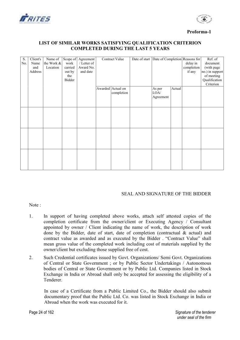
Proforma-1
LIST OF SIMILAR WORKS SATISFYING QUALIFICATION CRITERION
COMPLETED DURING THE LAST 5 YEARS
S.
No.
Client's
Name
and
Address
Name of
the Work &
Location
Scope of
work
carried
out by
the
Bidder
Agreement
/ Letter of
Award No.
and date
Contract Value Date of start Date of Completion Reasons for
delay in
completion
if any
Ref. of
document
(with page
no.) in support
of meeting
Qualification
Criterion
Awarded Actual on
completion
As per
LOA/
Agreement
Actual
SEAL AND SIGNATURE OF THE BIDDER
Note :
1. In support of having completed above works, attach self attested copies of the
completion certificate from the owner/client or Executing Agency / Consultant
appointed by owner / Client indicating the name of work, the description of work
done by the Bidder, date of start, date of completion (contractual & actual) and
contract value as awarded and as executed by the Bidder . “Contract Value” shall
mean gross value of the completed work including cost of materials supplied by the
owner/client but excluding those supplied free of cost.
2. Such Credential certificates issued by Govt. Organizations/ Semi Govt. Organizations
of Central or State Government ; or by Public Sector Undertakings / Autonomous
bodies of Central or State Government or by Public Ltd. Companies listed in Stock
Exchange in India or Abroad shall only be accepted for assessing the eligibility of a
Tenderer.
In case of a Certificate from a Public Limited Co., the Bidder should also submit
documentary proof that the Public Ltd. Co. was listed in Stock Exchange in India or
Abroad when the work was executed for it.
Page 25 of 162 Signature of the tenderer under seal of the firm
3. Information must be furnished for works carried out by the Bidder in his own name or
proportionate share as member of a Joint Venture. In the latter case details of contract
value including extent of financial participation by partners in that work should be
furnished.
4. If a Bidder has got a work executed through a Subcontractor on a back to back basis,
the Bidder cannot include such a work for his satisfying the Qualification Criterion
even if the Client has issued a Completion Certificate in favour of that Bidder.
5. Use a separate sheet for each partner in case of a Joint Venture.
6. Only similar works completed during the last 5 years prior to the last stipulated date
for submission of Bid, which meet the Qualification Criterion need be included in this
list.
Page 26 of 162 Signature of the tenderer under seal of the firm
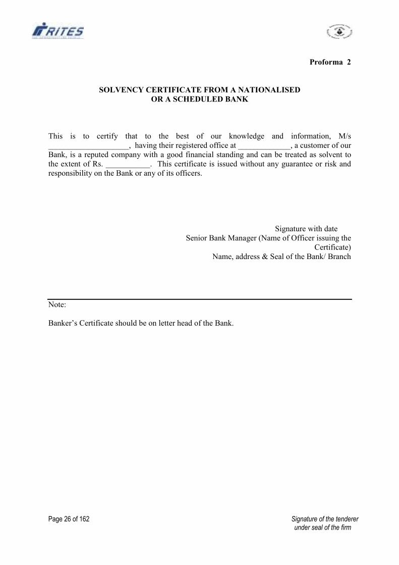
Proforma 2
SOLVENCY CERTIFICATE FROM A NATIONALISED
OR A SCHEDULED BANK
This is to certify that to the best of our knowledge and information, M/s
____________________, having their registered office at _____________, a customer of our
Bank, is a reputed company with a good financial standing and can be treated as solvent to
the extent of Rs. ___________. This certificate is issued without any guarantee or risk and
responsibility on the Bank or any of its officers.
Signature with date
Senior Bank Manager (Name of Officer issuing the
Certificate)
Name, address & Seal of the Bank/ Branch
Note:
Banker’s Certificate should be on letter head of the Bank.
Page 27 of 162 Signature of the tenderer under seal of the firm
Proforma 3
DECLARATION BY THE BIDDER
(Affidavit on Non-Judicial Stamp Paper of Rs.10/- duly attested by Notary / Magistrate)
This is to certify that We, M/s. __________________________, in submission of this offer
confirm that:-
i) We have not made any misleading or false representation in the forms, statements and
attachments in proof of the qualification requirements;
ii) During the past three years prior to deadline for submission of bids, no contract
awarded to us has been determined.
iii) No Central / State Government Department/ Public Sector Undertaking or Enterprise
of Central / State Government has banned/suspended business dealings with us as on
date.
iv) We have submitted all the supporting documents and furnished the relevant details as
per prescribed format.
v) List of Similar Works satisfying Qualification Criterion indicated in Proforma 1 does
not include any work which has been carried out by us through a Subcontractor on a
back to back basis.
vi) The information and documents submitted with the Tender and those to be submitted
subsequently by way of clarifications / making good deficient documents are correct
and we are fully responsible for the correctness of the information and documents
submitted by us.
vii) We have not failed to service the principal amount or interest or both of a loan
account/credit limit from nay Bank or Financial Institution during a period of one year
prior to the deadline for submission of bids.
viii) We understand that in case any statement/information/document furnished by us or to
be furnished by us in connection with this offer, is found to be incorrect or false, our
EMD in full will be forfeited and business dealings will be banned.
SEAL, SIGNATURE & NAME OF THE BIDDER
signing this document
Page 28 of 162 Signature of the tenderer under seal of the firm
ANNEXURE I A
CHECK LIST OF DOCUMENTS TO BE SUBMITTED
1. a) BY BIDDERS OTHER THAN JOINT VENTURES
i) Annual Financial Turnover
- Annual financial turnover for each of the last 3 Financial Years in
tabular
form.
- Self attested copies of Auditor’s Report along with the Balance Sheet
and Profit and Loss Statement for the relevant Financial Year in which
the minimum criterion is met (Refer Notes under Para 1 of Annexure
I).
ii) Work Experience
- Similar Work Experience : Proforma 1 of Annexure I with details of
1, 2 or 3 works as the case may be, which satisfy requisite qualification
criterion with self attested copies of supporting document (Refer Para
2a of Annexure I).
- Construction Experience in Key Activities/Specialised Components:
Tabular Statement giving contract-wise quantities executed in last 5
years along with documentary proof in support of having met the
criterion (Refer Para 2b of Annexure I).
iii) Solvency Certificate.
Suggested format at Proforma 2 of Annexure I (Refer Para 3 of Annexure I)
iv) Profitability
- Net profit of last 3 Financial Years in tabular form.
- Self attested copies of Auditor’s Report along with the Balance Sheets
and Profit and Loss Statements for last 5 or 3 Financial Years, as the
case may be (Refer Para 4 of Annexure I).
v) Net Worth
- Audited Balance Sheet for each of the last 3 Financial Years in tabular
form.
vi) Declaration by Bidder
Proforma 3 (Refer Para 6 of Annexure I)
vi) Integrity Pact (where applicable) : duly signed and witnessed in the format at
Annexure VIII (Refer para 11.7 of NIT & Instructions to Tenderers)

Page 29 of 162 Signature of the tenderer under seal of the firm
ANNEXURE II A
QUALIFICATION INFORMATION/CHECKLIST OF DOCUMENTS
--LETTER OF TRANSMITTAL BY OTHER THAN JOINT VENTURES
(on letter head of the Applicant)
From To
_____________ RITES Ltd._________
(Authority Inviting
Tender)
Sir,
Sub: Submission of Qualification information /documents as per Checklist.
1. I/We hereby submit the following documents in support of my/our satisfying the
Qualification Criteria laid down for the work:-
a) Self attested copy of a certificate, confirming that the applicant is a working
contractor or has executed any work within the last five years reckoned from the
date of opening of Tender, issued by a Government Organization/Semi
Government Organization of Central or State Government; or by Public Sector
Undertaking/Autonomous Body of Central or State government; or by a Public
Ltd. Company listed in Stock Exchange in India or Abroad.
b) Annual Financial Turnover
(i) Annual financial turnover for each of the last 3 Financial Years in a tabular
form.
(ii) Self attested copy of Auditor’s Report along with the Balance Sheet and
Profit and Loss Statement and Schedules for the relevant Financial Year in
which the minimum criterion is met, with calculations in support of the same.
c) Work Experience
i) Similar Work Experience :- In Proforma 1 with details of 1 / 2 / 3
works as applicable and self attested copies of supporting documents
as mentioned therein.
ii) Construction experience in key activities / specialised components:
Tabular Statement giving contract wise quantities executed in last 5
years with documentary proof.
d) Solvency Certificate - Proforma 2.
e) Profitability - Net profit of last 3 Financial years in tabular form with self
attested copies of Profit and Loss Statements for the last 3 Financial Years as
applicable.
f) Net Worth: Audited Balance Sheet for each of the last 3 Financial Years in
tabular form.
2. In addition the following supporting documents are also enclosed.
a) Self attested copy of Partnership Deed/Memorandum and Articles of
Association of the Firm.
Page 30 of 162 Signature of the tenderer under seal of the firm
b) Self attested copies of PAN/TAN issued by the Income Tax Department.
c) Declaration – Proforma 3
d) Self attested copy of Sales Tax, Works Contract Tax, Service Tax Registration
Certificate (as applicable).
e) Self attested copy of Registration under Labour Laws, like PF, ESI etc.
f) Self attested copy of ISO 9000 Certificate ( if any)
g) Integrity Pact (where applicable) : duly signed and witnessed.
3. I authorize you to approach any Bank, Individual, Employer, Firm or Corporation,
whether mentioned in the enclosed documents or not, to verify our competence and
general reputation.
4. I also enclose written Power of Attorney of the signatory of the Tender on behalf of
the Tenderer.
Yours faithfully,
Encl: As in Paras 1, 2 & 4
Signature of Applicant
with Name _________________
Date with seal
Page 31 of 162 Signature of the tenderer under seal of the firm
ANNEXURE II B (L)
QUALIFICATION INFORMATION /CHECKLIST OF DOCUMENTS
– LETTER OF TRANSMITTAL BY JOINT VENTURE
(FOR LARGE WORKS COSTING OVER Rs.100 CRORES)
(To be signed by the Lead Member on his Letter Head)
Deleted
Page 32 of 162 Signature of the tenderer under seal of the firm
ANNEXURE II B (N)
QUALIFICATION INFORMATION /CHECKLIST OF DOCUMENTS
- LETTER OF TRANSMITTAL BY JOINT VENTURE
(FOR NORMAL WORKS COSTING BETWEEN Rs.1 CRORE and Rs.100 CRORES)
(To be signed by the Lead Member in his Letter Head)
Deleted
Page 33 of 162 Signature of the tenderer under seal of the firm
ANNEXURE III
DRAFT MEMORANDUM OF UNDERSTANDING
EXECUTED BY MEMBERS OF THE CONSORTIUM / JOINT VENTURE
(On each firm’s Letter Head)
Deleted
Page 34 of 162 Signature of the tenderer under seal of the firm
ANNEXURE IV
FORMAT FOR POWER OF ATTORNEY TO AUTHORISED SIGNATORY
POWER OF ATTORNEY
(To be executed on non-judicial stamp paper of the appropriate value in accordance with
relevant Stamp Act. The stamp paper to be in the name of the firm/ company who is issuing
the Power of Attorney).
We, M/s.______ (name of the firm/company with address of the registered office) hereby
constitute, appoint and authorise Mr./Ms.______ (Name and residential address) who is
presently employed with us and holding the position of ______ and whose signature is given
below as our Attorney to do in our name and our behalf all or any of the acts, deeds or things
necessary or incidental to our bid for the work _____ (name of work), including signing
and submission of application / proposal, participating in the meetings, responding to
queries, submission of information / documents and generally to represent us in all the
dealings with RITES or any other Government Agency or any person, in connection with the
works until culmination of the process of bidding, till the Contract Agreement is entered into
with RITES and thereafter till the expiry of the Contract Agreement.
We hereby agree to ratify all acts, deeds and things lawfully done by our said Attorney
pursuant to this Power of Attorney and that all acts, deeds and things done by our aforesaid
Attorney shall always be deemed to have been done by us.
(Add in the case of a Consortium/Joint Venture)
Our firm is a Member/Lead Member of the Consortium of ___________, _________ and
___________.
Dated this the _____ day of ______ 20
(Signature and name of authorized signatory being given Power of Attorney)
___________
(Signature and name in block letters of *All the partners of the firm, * Authorized Signatory
for the Company)
(* Strike out whichever is not applicable)
Seal of firm/ Company
Witness 1: Witness 2:
Name: Name:
Address: Address:
Occupation: Occupation:
Notes:
- In case the Firm / Company is a Member of a Consortium/ JV, the authorized
signatory has to be the one employed by the Lead Member.
- The mode of execution of the Power of Attorney should be in accordance with the
procedure, if any, laid down by the applicable law and the charter documents of the
executant(s) and when it is so required the same should be under common seal affixed
in accordance with the required procedure.
Page 35 of 162 Signature of the tenderer under seal of the firm
ANNEXURE V
FORMAT FOR POWER OF ATTORNEY TO LEAD MEMBER OF CONSORTIUM /
JOINT VENTURE
(To be executed on non-judicial stamp paper of the appropriate value in accordance with
relevant Stamp Act. The stamp paper to be in the name of the company who is issuing the
Power of Attorney)
Deleted

Page 36 of 162 Signature of the tenderer under seal of the firm
ANNEXURE VI
Page 37 of 162 Signature of the tenderer under seal of the firm
ANNEXURE VII
FORM OF AGREEMENT
(ON NON JUDICIAL STAMP PAPER OF APPROPRIATE VALUE)
Agreement No. ________ dated _________
THIS AGREEMENT is made on ________ day of ______ Two thousand ________ between
RITES Ltd. a Government of India Enterprise and a Company registered under Companies
Act, 1956 having its registered office at SCOPE Minar, Laxmi Nagar, Delhi - 110092 and its
Corporate Office at RITES BHAWAN, Plot No.1, Sector 29, Gurgaon (Haryana)
representing through ____________, RITES LIMITED acting for and on behalf of and as an
Agent /Power of Attorney Holder of _____ hereinafter called the Employer (which
expression shall, wherever the context so demands or requires, include their successors in
office and assigns) on one part and M/s.______ hereinafter called the Contractor (which
expression shall wherever the context so demands or requires, include his/ their successors
and assigns) of the other part.
WHEREAS the Employer is desirous that certain works should be executed
viz.___________ (brief description of the work) and has by Letter of Acceptance dated ____
accepted a tender submitted by the Contractor for the execution, completion, remedying of
any defects therein and maintenance of such works at a total Contract Price of Rs. ______
(Rupees ______________ only)
NOW THIS AGREEMENT WITNESSETH as follows:-
1. In this Agreement words and expressions shall have the same meaning as are
respectively assigned to them in the Conditions of Contract hereinafter referred to.
2. The following documents in conjunction with addenda/ corrigenda to Tender
Documents shall be deemed to form and be read and construed as part of this
agreement viz.
The Letter of Acceptance dated______.
Priced Schedule (Bill) of Quantities
Notice Inviting Tender and Instructions to Tenderers.
RITES Tender and Contract Form
Special Conditions
Schedules A to F.
Technical Specifications
Drawings
Amendments to Tender Documents (List enclosed)
General Conditions of Contract (read with Correction Slip Nos. 1 to --) comprising of
(i) Conditions of Contract
(ii) Clauses of Contract
(iii) RITES Safety Code
(iv) RITES - Model Rules for the protection of Health and Sanitary
arrangements for Workers
(v) RITES – Contractor's Labour Regulations.
Page 38 of 162 Signature of the tenderer under seal of the firm
3. In consideration of the payment to be made by the Employer to the Contractor as
hereinafter mentioned, the Contractor hereby covenants with the Employer to execute,
complete, remedy defects therein and maintain the works in conformity in all respects
with the provisions of the Contract.
4. The Employer hereby covenants to pay to the Contractor in consideration of the
execution, completion, remedying of any defects therein and maintenance of the
works, the contract price or such other sum as may become payable under the
provisions of the contract at the time and in the manner prescribed by the Contract.
IN WITNESS whereof the parties hereto have caused their respective common seals to be
hereinto affixed (or have herewith set their respective hands and seals) the day and year first
above written.
SIGNED, SEALED AND DELIVERED BY
____________________________
In the capacity of _____
On behalf of M/s. _________
(The Contractor)
In the presence of
Witnesses (Signature, Name &
Designation)
1.
2.
______________________________
representing RITES LIMITED
In the capacity of Agent / Power of
Attorney Holder
For and on behalf of _________
(The Employer)
In the presence of
Witnesses (Signature, Name &
Designation)
1.
2.
Page 39 of 162 Signature of the tenderer under seal of the firm
ANNEXURE VIII
INTEGRITY PACT
Between
RITES LTD. acting for and on behalf of and as an Agent / Power of Attorney Holder of
____________hereinafter called the “Employer” AND
____________ hereinafter referred to as "The Bidder/Contractor"
Preamble
The Employer intends to award, under laid down organizational procedures, contract/s for
______________. The Employer values full compliance with all relevant laws and
regulations, and economic use of resources, and of fairness and transparency in his relations
with the Bidder/s and/or contractor/s.
In order to achieve these goals, the Employer will appoint an Independent External Monitor
(IEM) who will monitor the Tender process and execution of the contract for compliance
with the principles mentioned above.
Section 1 – Commitments of the Employer
(1) The Employer commits himself to take all measures necessary to prevent corruption
and to observe the following principles:-
1. No employee of the Employer, personally or through family members, will in
connection with the tender or for the execution of the contract, demand, take a
promise for or accept, for self or third person, any material or immaterial
benefit which the person is not legally entitled to.
2. The Employer will, during the tender process, treat all Bidders with equity and
reason. The Employer will in particular, before and during the tender process,
provide to all Bidders the same information and will not provide to any Bidder
confidential/additional information through which the Bidder could obtain an
advantage in relation to the tender process or the contract execution.
3. The Employer will exclude from the process all known prejudiced persons.
(2) If the Employer obtains information on the conduct of any of his employees which is
a criminal offence under the IPC (Indian Penal Code) /PC (Prevention of Corruption)
Act, or if there be a substantive suspicion in this regard, the Employer will inform its
Chief Vigilance Officer and in addition can initiate disciplinary action.
Page 40 of 162 Signature of the tenderer under seal of the firm
Section 2 – Commitments of the Bidder/Contractor
(1) The Bidder/Contractor commits himself to take all measures necessary to prevent
corruption. He commits himself to observe the following principles during his
participation in the tender process and during the contract execution.
1. The Bidder/Contractor will not directly or through any other person or firm,
offer, promise or give to any of the Employer’s employees involved in the
tender process or the execution of the contract or to any third person any
material or other benefit which he is not legally entitled to, in order to obtain
in exchange any advantage of any kind whatsoever during the tender process
or during the execution of the contract.
2. The Bidder/Contractor will not enter with other Bidders into any undisclosed
agreement or understanding, whether formal or informal. This applies in
particular to prices, specifications, certifications, subsidiary contracts,
submission or non-submission of bids or any other actions, to restrict
competitiveness or to introduce cartelization in the bidding process.
3. The Bidder/Contractor will not commit any offence under the relevant IPC/PC
Act; further the Bidder/ Contractor will not use improperly, for purposes of
competition or personal gain, or pass on to others, any information or
document provided by the Employer as part of the business relationship,
regarding plans, technical proposals and business details, including
information contained or transmitted electronically.
4. The Bidder/Contractor will, when presenting his bid, disclose any and all
payments he has made, is committed to or intends to make to agents, brokers
or any other intermediaries in connection with the award of the contract.
(2) The Bidder/ Contractor will not instigate third persons to commit offences outlined
above or be an accessory to such offences.
Section 3-Disqualification from tender process and exclusion from future contracts
If the Bidder/Contractor, before award or during execution has committed a
transgression through a violation of Section 2 above, or in any other form such as to
put his reliability or credibility in question, the Employer is entitled to disqualify the
Bidder/Contractor from the tender process or take action as per the procedure
mentioned in the "Guideline on banning of business dealing" annexed and marked as
Annexure "A".
Section 4- Compensation for Damages
(1) If the Employer has disqualified in terms of the provisions in Section 3, the
Bidder/Contractor from the tender process prior to the award of contract, the
Employer is entitled to demand and recover the damages equivalent to Earnest Money
Deposit/ Bid Security.
Page 41 of 162 Signature of the tenderer under seal of the firm
(2) If the Employer has terminated the contract during execution in terms of the
provisions under Section 3, the Employer shall be entitled to demand and recover
from the Contractor the damages equivalent to Earnest Money Deposit, Security
Deposits already recovered and Performance Guarantee, which shall be absolutely at
the disposal of the Employer.
Section -5 Previous transgression
(1) The Bidder/ Contractor declares that no previous transgression occurred in the last 3
years with any other Company in any country conforming to the Anti-Corruption
approach or with any other Public Sector Enterprise in India that could justify his
exclusion from the tender process.
(2) If the Bidder/Contractor makes incorrect statement on this subject, he can be
disqualified from the tender process or action can be taken as per the procedure
mentioned in "Guideline on banning of business dealing".
Section -6 Equal treatment of all Bidders/Contractors/Sub-Contractors
(1) The Bidder/Contractor undertakes to demand from all partners/sub-contractors (if
permitted under the conditions/ clauses of the contract) a commitment to act in
conformity with this Integrity Pact and to submit it to the Employer before signing the
contract.
(2) The Bidder/ Contractor confirms that any violation by any of his partners/sub-
contractors to act in conformity with the provisions of this Integrity Pact can be
construed as a violation by the Bidder/Contractor himself, leading to possible
Termination of Contract in terms of Section 4.
(3) The Employer will disqualify from the tender process all bidders who do not sign this
Pact or violate its provisions.
Section 7- Criminal charges against violating Bidders/Contractors/Sub-Contractors
If the Employer obtains knowledge of conduct of a Bidder, Contractor or Partners/Sub-
Contractor, or of an employee or a representative or an associate of a Bidder, Contractor or
Sub-Contractor, which constitutes corruption, or if the Employer has substantive suspicion in
this regard, the Employer will inform the same to its Chief Vigilance Officer.
Section -8 Independent External Monitor/Monitors
(1) The Employer shall appoint competent and credible Independent External Monitor for
this Pact. The task of the Monitor is to review independently and objectively, whether
and to what extent the parties comply with the obligations under this agreement.
(2) The Monitor is not subject to instructions by the representatives of the parties and will
perform his functions neutrally and independently. He will report to the MD/RITES
Ltd.
(3) The Bidder/Contractor accepts that the Monitor has the right of access without
restriction to all Project documentation of the Employer including that provided by
the Contractor. The Contractor will also grant the Monitor, upon his request and
Page 42 of 162 Signature of the tenderer under seal of the firm
demonstration of a valid interest, unrestricted and unconditional access to his project
documentation. The same is applicable to Partners/Sub-Contractors. The Monitor is
under contractual obligation to treat the information and documents of the
Bidder/Contractor/Partners/Sub-Contractor with confidentiality.
(4) The Employer will provide to the Monitor sufficient information about all meetings
among the parties related to the Project provided such meetings could have an impact
on the contractual relations between the Employer and the Contractor. The parties
offer to the Monitor the option to participate in such meetings.
(5) As soon as the Monitor notices or has reason to believe that violation of the
agreement by the Employer or the Bidder/ Contractor, has taken place, he will request
the Party concerned to discontinue or take corrective action , or to take any other
relevant action. The Monitor can in this regard submit non-binding
recommendations. Beyond this, the Monitor has no right to demand from the parties
that they act in a specific manner or refrain from action or tolerate action.
(6) The Monitor will submit a written report to the MD/RITES Ltd. within 8-10 weeks
from the date of reference or intimation to him by the Employer and should the
occasion arise, submit proposal for correcting problematic situations.
(7) If the Monitor has reported to the MD/RITES Ltd. of a substantiated suspicion of an
offence under relevant IPC/PC Act, and the MD/RITES Ltd. has not, within
reasonable time, taken visible action to proceed against such offender or reported it to
the Chief Vigilance Officer, the Monitor may also transmit this information directly to
the Central Vigilance Commissioner.
(8) The word Monitor would include both singular and plural.
Section – 9 Pact Duration
This pact begins when both parties have legally signed it. It expires for the Contractor when
his Security Deposit is released on completion of the Maintenance Period and for all other
Tenderers six months after the Contract has been awarded.
If any claim is made/lodged during this time the same shall be binding and continue to be
valid despite the lapse of this pact specified above, unless it is discharged/determined by
MD/RITES Ltd.
Section 10 Other Provisions
(1) This agreement is subject to Indian Law. Place of performance and jurisdiction shall
be as stated in the Contract Agreement.
(2) Changes and supplements as well as termination notices need to be made in writing.
(3) If the Contractor is a partnership or a consortium, this agreement must be signed by
the Partner in charge/ Lead Member nominated as being incharge and who holds the
Power of Attorney signed by legally authorised signatories of all the
Page 43 of 162 Signature of the tenderer under seal of the firm
partners/Members. The Memorandum of Understanding /Joint Venture Agreement
will incorporate a provision to the effect that all Members of the Consortium will
comply with the provisions in the Integrity Pact to be signed by the Lead Member on
behalf of the Consortium. Any violation of Section 2 above by any of the
Partners/Members will be construed as a violation by the consortium leading to
possible Termination of Contract in terms of Section 3
(4) Should one or several provisions of this agreement turn out to be invalid, the
remainder of this agreement remains valid. In this case, the parties will strive to come
to an agreement to their original intentions.
RITES Ltd.
Agent / Power of Attorney Holder
_________________________
_________________________
(For & on behalf of the Employer) (For the Bidder/Contractor)
(Office Seal) (Office Seal)
Place:…………………………
Date:……………………….
Witness 1:
(Name & Address) -----------------------------
-----------------------------
-----------------------------
-----------------------------
Witness 2
(Name & Address) -----------------------------
-----------------------------
-----------------------------
-----------------------------
Page 44 of 162 Signature of the tenderer under seal of the firm
ANNEXURE IX
Mandate Form
To
RITES Ltd.,
----------------
Dear Sir,
Authorization for payments through Electronic Fund Transfer System (RTGS/NEFT)
We hereby authorized RITES Ltd. To make all our payments, including refund of Earnest
Money, through Electronic Fund Transfer System (RTGS/NEFT). The details for facilitating
the payments are given below:-
(TO BE FILLED IN CAPITAL LETTERS)
1 NAME OF THE BENEFICIARY
2 ADDRESS WITH PIN CODE
3 (A)TELEPHONE NO WITH STD
CODE
(B) MOBILE NO.
4 BANK PARTICULARS
A BANK NAME
B BANK TELEPHONE WITH STD
CODE
C BRANCH ADDRESS WITH PIN
CODE
D BANK FAX NO WITH STD CODE
E 11 CHARACTER IFSC CODE OF THE
BANK (EITHER ENCLOSE A
CANCELLED CHEQUE OR OBTAIN
BANK CERTIFICATE AS
APPENDED)
F BANK ACCOUNT NUMBER AS
APPEARING ON THE CHEQUE
BOOK
G BANK ACCOUNT TYPE (TICK ONE) SAVINGS/ CURRENT/ LOAN/
CASH CREDIT/ OTHERS
H IF OTHERS, SPECIFY
5 PERMANENT ACCOUNT NUMBER
(PAN)
6 E-MAIL ADDRESS
I/We hereby declare that the particulars given above are correct and complete. If the
transaction is delayed or credit is not effected at all for reasons of incomplete or incorrect
information. I/We would not hold RITES Ltd. responsible. Bank charges for such transfer
will be borne by us.
Date____________ SIGNATURE
AUTHORISED SIGNATORY
Name________________________
Page 45 of 162 Signature of the tenderer under seal of the firm
BANK CERTIFICATION
It is certified that above mentioned beneficiary hold bank account
No.______________________ with our branch and the Bank particulars mentioned above
are correct.
SIGNATURE
Date___________
AUTHORISED SIGNATORY
Name______________________
OFFICIAL STAMP
Page 46 of 162 Signature of the tenderer under seal of the firm
ANNEX-A
Guidelines on Banning of Business Dealings
1. Introduction
1.1 RITES, being a Public Sector Enterprise and ‘State’, within the meaning of Article 12
of Constitution of India, has to ensure preservation of rights enshrined in Chapter III
of the Constitution. RITES has also to safeguard its commercial interests. It is not in
the interest of RITES to deal with Agencies who commit deception, fraud or other
misconduct in the execution of contracts awarded / orders issued to them. In order to
ensure compliance with the constitutional mandate, it is incumbent on RITES to
observe principles of natural justice before banning the business dealings with any
Agency.
1.2 Since banning of business dealings involves civil consequences for an Agency
concerned, it is incumbent that adequate opportunity of hearing is provided and the
explanation, if tendered, is considered before passing any order in this regard keeping in
view the facts and circumstances of the case.
2. Scope
2.1 The procedure of (i) Suspension and (ii) Banning of Business Dealing with Agencies,
has been laid down in these guidelines.
2.2 It is clarified that these guidelines do not deal with the decision of the Management
not to entertain any particular Agency due to its poor / inadequate performance or for
any other reason.
2.3 The banning shall be with prospective effect, i.e., future business dealings.
3. Definitions
In these Guidelines, unless the context otherwise requires:
i) `Bidder / Contractor / Supplier' in the context of these guidelines is indicated
as ‘Agency’.
ii) ‘Competent Authority’ and ‘Appellate Authority’ shall mean the following:
a) The Director shall be the ‘Competent Authority’ for the purpose of
these guidelines. MD, RITES shall be the ‘Appellate Authority’ in
respect of such cases.
b) MD, RITES shall have overall power to take suo-moto action on any
information available or received by him and pass such order(s) as he
may think appropriate, including modifying the order(s) passed by any
authority under these guidelines.
Page 47 of 162 Signature of the tenderer under seal of the firm
iii) ‘Investigating Department’ shall mean any Department, Division or Unit
investigating into the conduct of the Agency and shall include the Vigilance
Department, Central Bureau of Investigation, the State Police or any other
department set up by the Central or State Government having powers to
investigate.
4. Initiation of Banning / Suspension:
Action for banning / suspension business dealings with any Agency should be
initiated by the department/ unit having business dealings with them after noticing the
irregularities or misconduct on their part.
5. Suspension of Business Dealings
5.1 If the conduct of any Agency dealing with RITES is under investigation by any
department, the Competent Authority may consider whether the allegations under
investigation are of a serious nature and whether pending investigation, it would be
advisable to continue business dealing with the Agency. If the Competent Authority,
after consideration of the matter including the recommendation of the Investigating
Department/Unit, if any, decides that it would not be in the interest to continue
business dealings pending investigation, it may suspend business dealings with the
Agency. The order to this effect may indicate a brief of the charges under
investigation. The order of such suspension would operate for a period not more than
six months and may be communicated to the Agency as also to the Investigating
Department.
The Investigating Department/Unit may ensure that their investigation is completed
and whole process of final order is over within such period.
5.2 As far as possible, the existing contract(s) with the Agency may be continued unless
the Competent Authority, having regard to the circumstances of the case, decides
otherwise.
5.3 If the Agency concerned asks for detailed reasons of suspension, the Agency may be
informed that its conduct is under investigation. It is not necessary to enter into
correspondence or argument with the Agency at this stage.
5.4 It is not necessary to give any show-cause notice or personal hearing to the Agency
before issuing the order of suspension. However, if investigations are not complete in
six months time, the Competent Authority may extend the period of suspension by
another three months, during which period the investigations must be completed.
6. Grounds on which Banning of Business Dealings can be initiated
6.1 If the security consideration, including questions of loyalty of the Agency to the State,
so warrants;
6.2 If the Director / Owner of the Agency, proprietor or partner of the firm, is convicted
by a Court of Law for offences involving moral turpitude in relation to its business
Page 48 of 162 Signature of the tenderer under seal of the firm
dealings with the Government or any other public sector enterprises or RITES, during
the last five years;
6.3 If there is strong justification for believing that the Directors, Proprietors, Partners,
owner of the Agency have been guilty of malpractices such as bribery, corruption,
fraud, substitution of tenders, interpolations, etc;
6.4 If the Agency employs a public servant dismissed / removed or employs a person
convicted for an offence involving corruption or abetment of such offence;
6.5 If business dealings with the Agency have been banned by the Govt. or any other
public sector enterprise;
6.6 If the Agency has resorted to Corrupt, fraudulent practices including
misrepresentation of facts;
6.7 If the Agency uses intimidation / threatening or brings undue outside pressure on the
Company (RITES) or its official in acceptance / performances of the job under the
contract;
6.8 If the Agency indulges in repeated and / or deliberate use of delay tactics in
complying with contractual stipulations;
6.9 Based on the findings of the investigation report of CBI / Police against the Agency
for malafide / unlawful acts or improper conduct on his part in matters relating to the
Company (RITES) or even otherwise;
6.10 Established litigant nature of the Agency to derive undue benefit;
6.11 Continued poor performance of the Agency in several contracts;
(Note: The examples given above are only illustrative and not exhaustive. The
Competent Authority may decide to ban business dealing for any good and sufficient
reason).
7. Banning of Business Dealings
7.1 A decision to ban business dealings with any Agency shall apply throughout the
Company.
7.2 If the Competent Authority is prima-facie of view that action for banning business
dealings with the Agency is called for, a show-cause notice may be issued to the
Agency as per paragraph 8.1 and an enquiry held accordingly.
8. Show-cause Notice
8.1 In case where the Competent Authority decides that action against an Agency is
called for, a show-cause notice has to be issued to the Agency. Statement containing
the imputation of misconduct or mis-behaviour may be appended to the show-cause
Page 49 of 162 Signature of the tenderer under seal of the firm
notice and the Agency should be asked to submit within 30 days a written statement
in its defence. If no reply is received, the decision may be taken ex-parte.
8.2 If the Agency requests for inspection of any relevant document in possession of
RITES, necessary facility for inspection of documents may be provided.
8.3 After considering the reply of the Agency and other circumstances and facts of the
case, a final decision for Company-wide banning shall be taken by the Competent
Authority. The Competent Authority may consider and pass an appropriate speaking
order:
a) For exonerating the Agency if the charges are not established;
b) For banning the business dealing with the Agency.
8.4 The decision should be communicated to the Agency concerned along with a reasoned
order. If it decided to ban business dealings, the period for which the ban would be
operative may be mentioned.
9. Appeal against the Decision of the Competent Authority
9.1 The Agency may file an appeal against the order of the Competent Authority banning
business dealing, etc. The appeal shall lie to Appellate Authority. Such an appeal shall
be preferred within one month from the date of receipt of the order banning business
dealing, etc.
9.2 Appellate Authority would consider the appeal and pass appropriate order which shall
be communicated to the Agency as well as the Competent Authority.
10. Review of the Decision by the Competent Authority
Any petition / application filed by the Agency concerning the review of the banning
order passed originally by Competent Authority under the existing guidelines either
before or after filing of appeal before the Appellate Authority or after disposal of
appeal by the Appellate Authority, the review petition can be decided by the
Competent Authority upon disclosure of new facts /circumstances or subsequent
development necessitating such review.
11. Circulation of the names of Agencies with whom Business Dealings have been
banned.
11.1 Depending upon the gravity of misconduct established, the Competent Authority of
RITES may circulate the names of Agency with whom business dealings have been
banned, to the Ministry of Railways and PSUs of Railways, for such action as they
deem appropriate.
11.2 If Ministry of Railways or a Public Sector Undertaking of Railways request for more
information about the Agency with whom business dealings have been banned a copy
of the report of Inquiring Authority together with a copy of the order of the
Competent Authority/ Appellate Authority may be supplied.
Page 50 of 162 Signature of the tenderer under seal of the firm
12. Restoration
12.1 The validity of the banning order shall be for a specific time & on expiry of the same,
the banning order shall be considered as "withdrawn".
12.2 In case any agency applies for restoration of business prior to the expiry of the ban
order, depending upon merits of each case, the Competent Authority which had
passed the original banning orders may consider revocation of order of suspension of
business/lifting the ban on business dealings at an appropriate time. Copies of the
restoration orders shall be sent to all those offices where copies of Ban Orders had
been sent.
Page 51 of 162 Signature of the tenderer under seal of the firm
Section - 2
TENDER & CONTRACT FORM
Page 52 of 162 Signature of the tenderer under seal of the firm
SECTION 2
TENDER AND CONTRACT FORM FOR WORKS
To
__________________________
Tender Accepting Authority
Sub: TENDER FOR THE WORK OF ___________ ______________
(TENDER No. ______________________ ISSUED BY ____________)
TENDER
1. I/We have read and examined the Notice Inviting Tender and Instructions to
Tenderers, Special Conditions, Schedules A to F, Technical Specifications,
Drawings, Schedule / Bill of Quantities and General Conditions of Contract as well as
other documents and rules referred to in GCC and all the details contained in the
Tender Document for the work.
2. I/We hereby tender for the execution and completion of the work and remedy any
defects therein, specified in the Schedule of Quantities within the time specified in
Schedule “F”, and in accordance in all respects with the specifications, designs,
drawings and instructions in writing referred to in Notice Inviting Tender and
Instructions to Tenderers and in Clause 11 of the Clauses of Contract and with such
materials as are provided for, by, and in respects in accordance with, such conditions
so far as applicable.
3. We agree that our tender shall remain valid for a period of 90 days from the due date
for submission of bid or extended date as stipulated and not to make any
modifications in its terms and conditions.
4. A sum of Rs. ___________ (Rupees _________ only) is hereby forwarded in the form
of Banker’s cheque/Pay Order /Demand Draft issued in favour of RITES Ltd.,
payable at _________ as the Earnest Money. Mandate Form authorizing RITES Ltd.
To make all payments through RTGS/NEFT as per Annexure-IX duly filled in, is
enclosed.
5. If I/We withdraw my/our tender during the period of tender validity or before issue of
Letter of Acceptance which ever is earlier or make modifications in the Terms and
Conditions of the Tender which are not acceptable to the Employer, then the
Employer shall, without prejudice to any other right or remedy, be at liberty to forfeit
entire Earnest Money absolutely.
6. If I/We fail to furnish the prescribed Performance Guarantee and Additional
Performance Guarantee (if applicable) within prescribed period, I/We agree that the
said Employer shall, without prejudice to any other right or remedy, be at liberty to
forfeit the said Earnest Money absolutely.
7. If, I/We fail to commence the work within the specified period, I/We agree that the
Employer shall, without prejudice to any other right or remedy available in law, be at
liberty to forfeit the Earnest Money and Performance Guarantee and Additional
Performance Guarantee (if applicable) absolutely.
8. Further, I/We hereby agree that in case of forfeiture of Earnest Money or both Earnest
Money & Performance Guarantee and Additional Performance Guarantee (if
applicable) as aforesaid in paras 5 to 7, I/We shall be debarred from participation in
re-tendering process of the work.
Page 53 of 162 Signature of the tenderer under seal of the firm
9. On issue of Letter of Acceptance by the Employer, I/We agree that the said Earnest
Money shall be retained by the Employer towards Security Deposit, to execute all the
works referred to in the Tender document upon the Terms and Conditions contained
or referred to therein and to carry out such deviations as may be ordered, upto
maximum of the percentage mentioned in Schedule F at rates as stipulated in relevant
Clauses of contract and those in excess of that limit at the rates to be determined in
accordance with the provisions contained in Clauses 12.2 and 12.3 of the tender form.
10. I/We hereby agree that I/ We shall sign the Formal Agreement with the Employer
within 28 days from the date of issue of Letter of Acceptance. In case of any delay,
I/We agree that we shall not submit any Bill for Payment till the Contract Agreement
is signed.
11. I/We hereby declare that I/We shall treat the tender documents, drawings and other
records connected with the work as secret/confidential documents and shall not
communicate information derived there from to any person other than a person to
whom I/We am/are authorized to communicate the same or use the information in any
manner prejudicial to the safety of the Employer/State.
12. I/We hereby declare that I/We have not laid down any condition/deviation to any
content of Technical Bid and/or Financial Bid. I/We agree that in case any condition
is found to be quoted by us in the Technical and/or Financial Bid, my/our Tender may
be rejected.
13. I/We understand that the Employer is not bound to accept the lowest or any tender he
may receive. I/We also understand that the Employer reserves the right to accept the
whole or any part of the tender and I/We shall be bound to perform the same at the
rates quoted.
14. Until a formal agreement is prepared and executed, this bid together with our written
acceptance thereof shall constitute a binding contract between us and RITES.
15. I am/We are signing this Tender offer in my / our capacity as one/those authorized to
sign on behalf of my/our company/as one holding the Power of Attorney issued in my
favour as Lead Member by the Members of the Joint Venture.
Signature of Authorized Person/s
Date
Name/s & Title of Signatory
Name of Tenderer
Postal Address
Seal
Witness
Signature
Name
Postal Address
Occupation
Page 54 of 162 Signature of the tenderer under seal of the firm
Section - 3
SPECIAL CONDITIONS OF CONTRACT
Page 55 of 162 Signature of the tenderer under seal of the firm
Section – 3
1. SPECIAL CONDITIONS OF CONTRACT
1. The tenderer shall hold the offer open till such date as may be specified in the tender.
It is understood that the tender documents have been sold/issued to the tenderer
and the tenderer is being permitted to tender in consideration of the stipulations on
his part that after submitting his tender, he will not resile from his offer or
modify the terms and conditions thereof, in a manner not acceptable to RITES.
2. Should the tenderer fail to observe or comply with the foregoing stipulations,
amount deposited as Earnest Money for the due performance of the above stipulations
shall be forfeited to RITES. Earnest Money of the successful tenderer will be
adjusted against initial Security Deposit for the due and faithful fulfillment of the
contract. Recovery of Security Deposit will be made from on account bills of the
contractor till the required amount of Security Deposit is recovered. The Security
Deposit will be refunded on successful completion of the contract. No interest will be
paid on any amount recovered by way of Security Deposit or amount lying due to the
contractor.
3. Income Tax will be deducted as per rule. All local taxes or levies, if any, by
Government or local bodies will be borne by the Contractor.
4. If a tenderer expires after the submission of his tender or after the acceptance of his
tender, RITES shall deem such tender as cancelled. If a partner of a firm expires after
the submission of their tender or after the acceptance of their tender, RITES shall
deem such tender as cancelled unless the firm retains its character.
5. RITES also reserves the right to accept tender either for full quantity of work or part
thereof or divide the works amongst more than one without assigning any reason for
any such action.
6. When the tender is submitted by the tenderer(s), it will be understood that the
tenderer(s) has/have gone through carefully in detail all the instructions,
conditions, general and special conditions of contract all general and special
instructions/ specifications for execution of the work and that the tenderer(s) has/have
got himself/ themselves clarified on all points and doubts and interpretations by the
proper authority of RITES Administration.
7. Contractor's store houses, yards etc. for stocking materials issued by RITES shall be
located in the site premises only at locations approved by Engineer-in-charge at site.
8. The Construction of B.G. railway track work consists of laying & linking of railway
track on PSC sleeper layout & laying and linking of Points & Crossings laid with 60
rails on PSC Sleepers of required density, including supply of hard stone ballast of
approved quality and other P. way materials, the works also inclusive of earth work in
formation and construction of HP bridges, RCC bridges etc. The work shall conform
to various specification indicated in Indian Railway P.Way Manual, track Manual
and other Permanent Way I.R.S. Drawings in use by Indian Railways for such
works, and should be fit for use of Broad Gauge engines, Rolling Stock etc.
Page 56 of 162 Signature of the tenderer under seal of the firm
9. If there is any conflict between instructions given in schedule & conditions
mentioned in the special conditions, the schedule shall be observed.
10. The contract period may be extended by RITES on behalf of SECL, for the minimum
required period i.e. up to the period for completion of works granted by SECL. The
rates quoted by the tenderer(s) and accepted by RITES Administration must hold
good till the completion of entire work.
11. Before commencing the work, joint inventory of existing materials in the track is
to be taken by the representatives of RITES, SECL and the contractor and entered
in the inventory register and jointly signed.
12. The P. Way materials as per "Schedule of Quantities” in the tender documents
required for the work shall have to be supplied by the contractor to the Client/ RITES
and shall be kept at the suitable store/stock yard of RITES/SECL nominated by SECL
authority.
13. The Contractor shall produce an Indemnity Bond on Non Judicial stamp paper of Rs.
100/- (Rupees One Hundred) only as guarantee for the quality of the materials
supplied by them and also to secure the security of the materials against any type of
theft till obtaining the completion certificate of the works from RITES as well as from
SECL authority.
14. Adequate protection should be made while moving on public Roads or adjacent and
across railway tracks. The rates quoted shall include cost of these items. Similarly
the excess materials shall be returned to the nominated stores of the SECL. No
separate payments will be made extra for these items except otherwise mentioned.
The contract shall include such expenses for items in the "SCHEDULE OF
QUANTITIES".
15. The contractor will be responsible for the safe custody of P- Way materials
issued to him till completion of the works and handing over the Track. The
contractor will also responsible to account for the P-Way materials issued to him
and surplus if any has to be returned by him at his cost at the depot from which these
were issued. For P. Way materials remaining not accounted for by contractor being
laid on track or returned to the depot, recovery will be effected from the contractor's
dues at rates to be decided by the tender accepting authority which will be final and
binding.
16. RITES shall not supply any equipment, tools and machinery.
17. It should be clearly understood that it is entirely the contractors responsibility
and liability to find, procure and use the required tools and plants and accessories at
his own cost for efficient and methodical execution of the work. RITES shall have
the right to check the sufficiency and quality of the Contractor's tools from time to
time and the Contractor shall carry out all reasonable instructions of RITES in this
respect.
Page 57 of 162 Signature of the tenderer under seal of the firm
18. In the event of any accident at the work spot, or while transporting P. Way materials,
if it is established by the enquiry by RITES representative/Clients' representatives or
Railway/local Civil authority that the accident occurred wholly or partly due to any
act tantamount to negligence on part of the contractor, he shall render himself liable
for all damages and also legal proceedings.
19. The contractor will be responsible for the released materials and fittings till such time
they are handed over to the RITES/SECL at nominated place/places jointly identified
through contractor's transport and labour as per direction of Engineer in-charge of
RITES.
20. The labour engaged by the contractor for the works should be headed by a railway
retired Permanent Way Inspector employed by the contractor who is conversant with
the execution and maintenance of P. Way works including safety rules.
21. In case the released P. Way materials are left over at site, the contractor has to
employ/deploy security/chowkidars day and night at his own cost till the P. Way
materials are handed over to the RITES/SECL at their nominated depot. Till the
return/handed over of all released materials at the nominated depot, the released
materials will continue to remain in the custody of the contractor.
22. Shifting of labour camp from place to place as the work advances will be at the cost
of the contractor himself.
23. The contractor will co-operate with the Engineer-in-Charge in maintaining various
registers, charts and records etc. in connection with the works.
24. The following registers will be maintained by the RITES representative at the cost of
contractor who should sign the registers so maintained by RITES in token of his
acceptance of the entries made therein.
i. Register of material issued.
ii. Register of site order.
iii. Register of materials laid in track.
iv. Register of materials received back from contractor.
v. Register of ballast stacks.
vi. Register of through packing.
vii. Register for compaction of blanketing materials
25. A separate registers should also be maintained by the contractor for the deployment
and payment of labour at site as per law of contract labour. The registers should be
made available to Client’s personnel, as and when required.
26. For transportation of P. Way material both new and released the contractor has to
engage his own labour, tools and plants and transport and the rates quoted shall be
inclusive of all these charges except otherwise mentioned in the Schedule of
Quantities.
27. While stacking P. Way materials (new or second hand or released) on cess/side, care
should be exercised to ensure that those stacks do not infringe the Railway's moving
dimensions.
Page 58 of 162 Signature of the tenderer under seal of the firm
28. The work of track linking at level crossings will be taken up only when specifically
authorised by RITES representative after giving due notice to road users. The road
surface will be made good on completion of works at contractor’s cost, to the original
standard. No extra payment for digging up road surface for the work and restoring the
road surface will be admissible for work at level crossings.
29. The work will be carried out on a fixed Programme approved by the Engineer-
in-Charge.
30. Time shall be regarded as the essence of the contract and failure on the part of
contractor to complete the work by the date stipulated in the agreement and work
orders will entitle RITES Administration to recover liquidated damages/penalty.
31. RITES Administration reserve the right to alter the detailed plan and sections and
to carry out minor alteration in the plans resulting in corresponding increase or
decrease in the quantity of works without being liable to pay enhanced rates for the
work or to allow extra time for completion of the work.
32. No new facilities such as roads, level crossing etc other than those already in
existence will be made available to the contractor.
33. The contractor shall make his own arrangement at his own cost for the construction of
service roads for the transport of materials. No separate payment shall be admissible
to the contractor for construction of roads, or their repairs and maintenance.
34. RITES will have the right to use the service roads at all times without any payment to
the contractor.
35. The Schedule of items of work to be carried out, provided in the SCHEDULE OF
QUANTITIES” gives only brief description of each of the items. Execution of these
items will be governed by the specifications. For detailed specifications, Indian
Railway Permanent Way Manual and Track manual and IRS drawings shall be
applicable. RITES' representative at site will be fully empowered to provide guidance
in the matter of execution of the works and his instructions will be final and binding
in this regard.
36. The contractor must engage workmen, artisan and supervisors having competence and
experience in doing P-Way works of various nature.
37. In case any workman is found incompetent or otherwise undesirable by the RITES'
representative at site, he should not be allowed to work under the Contractor. In this
matter, the opinion of the Engineer-in-Charge will final and binding on the contractor.
Any violation of this requirement by the Contractor shall be treated as fundamental
breach of contract entitling RITES to rescind the contract by giving 7 days notice.
38. Particulars of work done during each day, with location where the work is done, will
have to be recorded in a register by the Contractor’s site in charge and the register will
be kept available for inspection/scrutiny by RITES’ representative. A site order book
will also have to be maintained where instructions regarding work to be carried out
will be recorded by RITES' representative at site.
Page 59 of 162 Signature of the tenderer under seal of the firm
39. Sufficient number of security/Chowkidars will be arranged by the contractor at his
own cost for guarding all materials issued to him. He will also arrange to guard the
track at his own cost against theft of any fittings till the track is handed over to
Clients.
40. The contractor shall ordinarily deploy his men during day light hours. RITES's
representative shall have the right at all times to supervise the contractor's work and
instruct the contractor and the contractor shall execute the work as per the instructions
without any lapse of time. For this purpose the Contractor shall maintain a Site
Order Book.
Failure comply with RITES' representative's instructions shall be deemed to be a
fundamental breach of contract on the part of the Contractor entitling RITES to
rescind the Contract at the Contractor's risk and cost after serving a notice of 7 days.
41. On-account payments to Contractor shall be made periodically based on the quantity
and item of work executed at the rates accepted under this contract, and upon a
certificate by the RITES' representative that work has been done to proper
specification and to the satisfaction of the representative.
42. The Contractor will make all arrangements for getting passes/authorities for his men
including making necessary application with photos for each labourer deployed for
this work and will bear all costs, any. Housing accommodation and watering
arrangements for contractor's labour will have to be arranged by the contractor.
43. Every month the Contractor will issue a Certificate to RITES about having made full
payment to all labourers engaged for this work under him as per minimum wages act
of Chhattisgarh State. Payment of RA and final bill will be released only after
submission of this certificate.
44. The Contractor will bear all medical expenses and make immediate arrangement for
medical attention to his labourer, if injured on duty. He will provide "Medical Aid"
Box at site of work at his cost.
45. Every precaution should be taken to avoid any accident or injury to the labourers, for
which look-out-men will have to be kept by the contractor at his own cost, as
required.
46. The contractor should indemnify and save harmless RITES/client against any claims
on account of accident to labourers similar occurrence for any reason whatsoever.
47. Before commencement of the work, the contractor shall set out and also erect
suitable pillars for reference during construction and thereafter to check the
alignment and level. The cost of construction of such pillars and maintenance thereof
shall be borne by contractor. No separate payment shall be made for such works.
48. The work is also involve in running line of Bhatgaon railway siding of M/S SECL at
Bhatgaon Area which necessitate safety precaution to be taken for labour as well as to
the moving vehicle.
Page 60 of 162 Signature of the tenderer under seal of the firm
49. The work will be executed in running operational track. Contractor should carry the
normal works like sleeper renewal, deep screening, through packing of the track
ballast etc in the running track without any traffic block and without effecting the
traffic operation.
For works like renewal of points and crossings, overhauling of level crossing etc
contractors should co-ordinate with officials of RITES, SECL Bhatgaon Area and
local Railway authority to obtain necessary traffic block, if required, well in advance
during execution of the work so that traffic operation remains unaffected.
50. All sorts of precautions and safety are to be assured by the contractor for the track
under execution of work/ under their possession, so that no derailments of wagons
and/or rolling stock take place.
51. In the event of accident like derailment, capsizement of wagons/rolling stock, RITES
Engineer- In- Charge of the work or their representative, official of SECL Bhatgaon
Area and official of SEC Rly. Will represent in joint enquiry. Where the cause of
derailment establish due to the fault of contractor’s unsafe work, the charges for
rerailment of wagons and/or rolling stock and all incidental charges are to be
recovered from the contractor’s payment.
52. Operation involving re-railing of derailed wagons and/ or rolling stock is, however,
outside the purview of the work, since Railway resources will have to be arranged for
this purpose as per the existing procedure by SECL.
53. The contractor should arrange adequate nos. of labourers for execution of the works
like renewal of rails, renewal of points and crossings etc to be executed under the
traffic block. Such works shall be planned at least one week in advance jointly with
the representative of RITES and SECL for block period. In event of non-availability
or postponed of block period, the contractor should use those labourers for other
connected works. No compensation will be made for such idle labourers.
54. The tenderer should visit the site to select suitable place for stacking of stone ballast
(as mentioned in the schedule of quantities) as well as for other works before
submission of their offer.
55. The payment for supply as well as for spreading of ballast as specified will be made
based on the joint measurement (with representative of RITES, SECL and the
contractor) of stone ballast without deduction of any shrinkage. 90 % payment for
supply of ballast shall be released on the quantity accepted and balance 10%
shall be released after spreading the same in the track.
56. Measurements of all works involving for the work of Balance work of Laying &
Linking of Railway track including supply of ballast & other P.Way materials in
connection with Construction Management and arrangement of new Railway
Siding for rapid loading system at Junadih Siding of Gevra Area at Gevra Distt.
Korba(C.G.)
Page 61 of 162 Signature of the tenderer under seal of the firm
57. The contractor shall have to take over the possession of the stone ballast just after
measurement and shall spread the same as directed by the Engineer-In-Charge or
authorized representative at site. Contractor shall ensure that the measured ballast will
be safely spreaded into track and no ballast shall be theft from the site by any means.
58. Consumable stores/materials of approved quality required for the works such as
grease, oil, paint etc. shall be arranged by the contractor at no extra cost over and
above the accepted rate of the concerned item.
59. All the P. Way tools such as (a) Rail tongs, (b) Crow bars, (c) Fishing spanners, (d)
Hammers, (e) Keying hammers, (f) Cotter splitters, (g) Shovels, (h) Motar Pans, (i)
Beaters, (j) Track lifting jacks, (k) Gauges, (l) Level board, (m) Sprit level, (n) Cant
board, (o) Expansion Liners, (p) Wooden Squares, (q) Steel tape, (r) Wire brushes, (s)
Cotton waster (t) Rake ballast, etc, as required for the work depending on the labour
strength will be arranged by the contractor at his own cost.
60. Before putting into track, the central leg of elastic rail clips should be thoroughly
cleaned and grease (to IS: 400-1981, specifications for Grease No. ‘O’ Graphite) and
eye of inserts. The rates accepted include the cost of the greasing.
61. During execution of work, contractor should arrange for protection of track by
displaying the signals as per extent rule of Indian Railway. The person deployed by
the contractor for track works shall go through the competency test conducted by
Railway if Railway desired.
62. Defect Liability Maintenance: In case any defect is noticed/developed in the track
due to defective workmanship or due to failure of materials supplied by the contractor
during/after completion of the work within 03(three) months the same has/have to be
rectified free of cost immediately on receipt of instruction from Engineer-In Charge
failing which necessary deduction will be made from the contractor’s bills or any
other dues towards cost of rectifications.
63. No ‘ Way Bills” and “3” Form will be issued by RITES/SECL in respect of supply
of P.Way materials under Schedule ‘3’, ‘4’ and ‘5’. Contractor shall have to arrange
the way bill at their own cost. Tenderes are requested to quote accordingly.
64. The Contractor should get materials under Schedule – 3, 4, & 5 inspected by
RITES Inspection wings/ Zonal Railways as the case may be before effecting
dispatch. Inspection certificates have to be produce in support of making such
inspection for all materials under Sch- 3, 4, & 5.
65. RITES Project Office on behalf of clients also reserves the right to undertake any
testing of the materials, if necessary before acceptance of the materials.
66. Any materials and accessories, found to be damaged at the time of receipt will not be
accepted and shall have to be replaced by good ones free of cost after being duly
inspected and passed by Inspecting authorities.
67. 90% payment will be released on receipt of the materials under Sch- 3, 4, & 5. and
balance 10% payment will be released after putting / insertion in to the track.
Page 62 of 162 Signature of the tenderer under seal of the firm
68. Materials under Sch- 3, 4, & 5. should be procured from Railway Board’s/ Zonal
Railway’s/RDSO approved manufactures/ suppliers.
69 The work is within restricted area of SECL. Necessary Permits for labour, staff
and vehicle for entering into the said zone are to be made by contractor from SECL
office. A list of labour, staff and vehicle are to be submitted to Engineer-In-Charge
of RITES for forwarding the same to appropriate authority.
70 Contractor is also wholly responsible for custodian of track
renovated/upgraded/modified by them including materials thereon from
theft/damage/pilferage till handing over of the full length track to the client.
Handing over of track will only done only after total length of track will be
renovated.
71 Consignee Of Materials: All P. Way materials/fittings, PSC sleepers, Points &
Crossings etc. will be received by Site In-Charge, RITES Ltd., or his authorized
representative on behalf of Gevra Area / SECL, Gevra, Distt. Korba, Chhattisgarh.
72 Invoice of materials are to be made in the name of Engineer-In-Charge, SECL,
Bhatgaon Area through Site In-Charge, RITES Ltd., Gevra.
73 Place of delivery: SECL Store, Gevra Area or the nominated place by
authority of SECL Gevra Area.
74 The contractor will have to submit the Royalty Clearance Certificate of the Ballast
or all other miners minerals used for the said works issued by the concerned
authority. If the contractor fails to submit the royalty clearance certificate then the
amount will be deducted as per extent rule of the concerned department in the state
of Chhattisgarh.
75 The contractor shall execute necessary Transit Insurance for the transportation of
60Kg rails, PSC sleepers, points & Crossings and other p-way materials.
76 There will be no Arbitration Clause for this contract.
77 Efforts shall be made to settle the disputes amicably. In any case CMD/SECL's
decision in any dispute shall be final. As regards the disputes, if any, will be subject
to Kolkata jurisdiction only.
Page 63 of 162 Signature of the tenderer under seal of the firm
2. Special conditions for supply of ballast
1.1 The rates, as per the Schedule, are inclusive of all taxes viz. commercial sales tax,
octroi etc. and other charges levied by the State / Central government. The rate also
includes all lead, lift, ascent, descent, loading, unloading, royalty etc. and all other
incidental charges.
1.2 The contractor shall stack the ballast, normally over the entire length of the section at
specified locations duly certified by the Engineer-in-Charge except at those certain
locations which are found to be inaccessible for certain reasons. The decision of
Engineer-in-Charge at site will be final and binding on the contract for the locations,
inaccessible for supply of ballast.
1.3 The ballast shall be supplied as per the requirement given by the In-Charge at site.
1.4 The ballast shall be in conformity with “Specifications for Track Ballast”
(Enclosed). However, the RITES administration may alter these conditions of
technical nature, which do not have bearing on rates.
1.5 The tenderer must submit the test report of impact value, Abrasion value and water
Absorption value from any of the approved laboratories along with the tender
indicating the name of quarry/quarries from where supply is intended.
i) Any Zonal Railway Laboratory or any Railway approved Laboratory/
Institution.
ii) National Test House, Alipore, Kolkata
iii) RITES Laboratory (where available),
iv) Any Govt. laboratory/institution
* The test report should not be more than 90 (ninety) days old from the date of
opening of the tender.
1.6 The tenderer/contractor undertakes that the ballast supply at all times shall conform to
Specifications for track ballast as specified by RITES.
1.7 The contractor shall make his own arrangement at his own cost for the construction of
service roads within the Project site as well as outside Project site for transportation
of ballast, if required. No separate payment shall be admissible to the contractor for
the construction of such roads and its repairs & maintenance.
1.8 The contractor shall have to make necessary arrangement for leveling the nominated
grounds for stacking of ballast at cess, as per the direction and to the satisfaction of
Engineer-in-Charge, without any additional claim of payment.
1.9 The contractor shall submit the name of the quarry/quarries along with the tender
from where the contractor is intending to supply the ballast.
Page 64 of 162 Signature of the tenderer under seal of the firm
1.10 The cost of routine testing of ballast, as per RDSO guidelines shall be payable by the
contractor. However the RITES is at liberty to collect the ballast sample as and when,
required and send the same for testing at the cost of Contractor.
1.11 The quantities of ballast mentioned in the schedule are approximate. RITES reserves
the right to alter the quantity as per the actual requirement and nothing extra will be
payable over and above the accepted rates. However, for increase in agreemental
value beyond 25%, clause 12.2 (Deviation, Deviated quantities, pricing) of
General Conditions of Contract will be applicable.
1.12 The contractor shall make necessary arrangement for the security of the ballast
supplied during the progress of the work till final bill is paid. No separate payment
shall be admissible to the contractor for guarding the ballast.
1.13 The ballast shall be supplied as per the requirement given by the Site Engineer.
Quantity supplied extra over the required quantity may not be paid.
1.14 Safety of ballast against any theft or loss remains solely with the contractor during the
entire period of the contract agreement and the same has to be made good by
contractor. This responsibility of the contractor remains even if the ballast stacks are
measured and paid for, unless RITES /EMPLOYER takes over measured ballast
stacks from the contractor with a clear taking over certificate.
1.15 The Stone ballast should be machine crushed and shall consist of hard and durable
and as far as possible angular along edges/corners, free from weathered portions of
parent rock, organic impurities and inorganic residues. Along with the tender the
Tenderer test certificate for physical properties in accordance with IS: 2386 (Part-IV)-
1963 that shall be supplied by him.
1.16 The Tenderer should mention in the tender the name of quarry from where the ballast is
proposed to be supplied and the distance of the quarry from site.
1.17 The stone ballast should be got inspected by the Engineer at regular intervals to ensure
quality and samples tested for physical properties (abrasion test, impact test and water
absorption test values).
1.18 Attempts should be made to have ballast of the best available quality. For approving
the ballast quarry, the following norms will be adopted: -
1.19 90% of the payment will be paid in R.A. bills prepared against supply of ballast duly
certified by Engineer-in-Charge of RITES Ltd supported with measurement details,
test certificates, royalties and all other necessary statutory taxes clearance certificates.
Balance 10% shall be released after spreading the same in to the track
1.20 The rates in this schedule are entirely inclusive so as to cover any purchase and/or
royalties and / or compensation for surface charges incurred by him whatsoever. The
accepted rate includes all quarry charges Sales Tax monopoly fee and other charges if
any and tools and plants for clearing site for stacking, test and testing screens, carriage
of materials to the site of stacking and removal of any material rejected by the
Engineer to any site when the rejected materials are to be thrown.
Page 65 of 162 Signature of the tenderer under seal of the firm
1.21 The rates quoted are inclusive of all charges including all taxes levied by Union of
India or State Government or local bodies and include Sales Tax, Royalty, Octroi
duties etc.
--OOO--
Page 66 of 162 Signature of the tenderer under seal of the firm
3.SPECIAL CONDITIONS OF CONTRACT FOR THERMIT WELDING
The work consists of welding in situ 52 Kg. rail (72 UTS/90 UTS) joints by Short preheat
welding (SKV welding) process.
1. The 'portion' used for welding shall conform to the technical requirements as
mentioned in IRS: T-19-1994. The suitability of the 'portion' for the welding process
in respect of the type and section of rails to be welded shall be ensured before
commencing welding. Only RDSO certified/passed portions should be used for
welding.
2. The contractor shall execute the work at the rates and terms and conditions specified
in the contract and within the time schedule as indicated in the Work Orders.
3. The work done shall conform to IRS Specification No. T-19-1994 for fusion welding
of rails by alumino Thermit process. A copy of this specification is attached as
Annexure "A" stipulation laid down therein shall apply to this except as modified or
clause herein under.
4. No payment will be made for the spoilt joint exceeds 2% of the total of good joints.
5. The RITES will make available rail pieces for making welds specified in clause
3.5.1 of the Annexure-"A" free of charge.
6. A guarantee as specified in clause 3.6.1/3.5.2 of Annexure shall be furnished by the
contractor for the completed weld joints against Work Order.
7. The marking of welded joints as specified in clause 3.6.3 of the Annexure "A" shall
be done by the contractor at his cost.
8. The contractor shall procure all the necessary welding materials as well as all the
equipments for the welding works so as to use a finished weld including the necessary
plaIning equipments at his own cost and he will be paid only for the finished work at
rates quoted in the Schedule of items.
9. The contractor shall provide all labour required for the work and the contractor
shall arrange to train the labour in the welding technic and shall also be responsible
for providing constant technical supervision during the process of welding work. The
welder should be RDSO trained and certified by RDSO. The welders certificate
obtained from RDSO shall have to be furnished prior to start of work for welding.
10. The contractor shall be responsible for the correct alignment and welding of the rails
and for the proper plain by hand filing of the welds and their finish. The files are to be
supplied by the contractor at his cost.
a) The contractor shall provide pieces of wooden sleeper wedges and such other
tools which are required for lifting or making or placing rail in position for
welding purpose and also hammer and hot and cold sets required for the
works.
Page 67 of 162 Signature of the tenderer under seal of the firm
(b) The contractor shall provide fuel like petrol required for welding at the rate
of 2.00 liters of petrol per joint. The quantities may vary within 10%.
c) All other equipments & machinaries used by the contractor in grinding or
plaining etc. should be worked out by him at his own cost including labour
for this work.
11. The contractor shall arrange his own facilities for carrying out of all plants &
equipment and materials from nearest store to site of work.
12. The Contractor shall arrange storage accommodation for his plants & equipments as
close to the site of work.
13. The contractor shall not carry out any works between sunset and sunrise. He should
make his own arrangement to protect the work against wind and weather in the course
of execution of work.
14. Payment shall be made for acceptable joints in terms of the agreement and for the
spoilt joints upto 2% of the total of good joints. Further joints which will be put for
tests, the contractor will be paid provided they stand the test. Test joints which will be
failed will not be paid for.
15. The rate for welding work shall bear all inclusive tax.
16. The contractor shall be responsible for the welded joints remaining satisfactory for
the guarantee periods as specified in Annexure-"A" and every joint failing during this
period 3 times the cost of one weld will be recovered from the amount due to him. If
it is decided by the RITES that the cracked welded joint will not be rewelded free of
by the contractor in terms of clause 3.5.2 of Annex-"A".
17. The account of sealed approved portions and statement of issue of approved portion
shall be maintained by the RITES representative of the welding but the account and
statement in question will have to be countersigned by the authorised representative
of the contractor. The account shall correlate the welding panel on the pieces number
with the approved portion and the date of welding.
18. In the event of failure of weld joints which are not possible to weld on that very
day, the joints must invariably be fastened with joggled fish plates duly clamped.
The joggle fish plates and clamps are to be arranged by the contractor at his own
cost.
19. The plants, equipments, consumables materials, Technical Supervisors, Artisen
staff, Welders and other labours required for the work shall have to be arranged by
the contractor at his own cost.
20. Any electric supply required at site for what-so-ever purpose shall be arranged by
the contractor at his own cost and rates quoted shall include the cost of providing
electric supply arrangements required for the work.
Page 68 of 162 Signature of the tenderer under seal of the firm
21 Sample test joint.
21.1 One out of every 100 joints welded shall be selected at random by the purchaser or
by the inspecting officer within one month of welding and subjected to
hardness, transverse load/ deflection tests and porosity as per clause 4.2 of IRS:T-
19-1994 ( reproduced partly as Annexure 9 for ready reference) and the joint shall
comply with the provisions laid downs therein.
21.2 If the sample test joint fails to satisfy any of the requirements of specification
IRS-T-19-1994, the RITES will be at liberty to suspend further welding. However,
two more randomly selected joints from the same lot of 100 joints shall be subjected
to re-tests as per clause 1.1 of IRS-T-19-1994. Both the joints should clear all the
tests. If this report is also not satisfactory, further welding of joints shall be
suspended until the firm's welding technique has been examined and the same
satisfies the requirements of IRS:T-19-1994.
22 Guarantee
22.1 Rail joints welded by a firm shall be guaranteed against failure for a period of one
year from the date of welding the joints in track or from the date such welded joints
made 'in cess' are inserted in the track. Any such welded joint which fails within
the guarantee period shall be rewelded free of cost by firm as per stipulations of para
3.4
22.2 In case of failure of sample test joint ( refer para 3.5), the period of guarantee for 100
joints represented by the sample joint shall be extended for a further period of one
year. In case of failure of joints or joints exhibiting signs of failure by cracking
within extended period of guarantee, the joints shall be rewelded free of cost by
the supplier as per stipulations of para 3.4.
22.3 The welded joints with the extended period of guarantee shall be marked 'X' with
yellow paint one the outer side of the web of the rail near the joint in addition to
the marking prescribed in para 2.6. Such marked joints shall be kept under careful
observation by the purchaser.
Page 69 of 162 Signature of the tenderer under seal of the firm
Section - 4
SCHEDULES A TO F
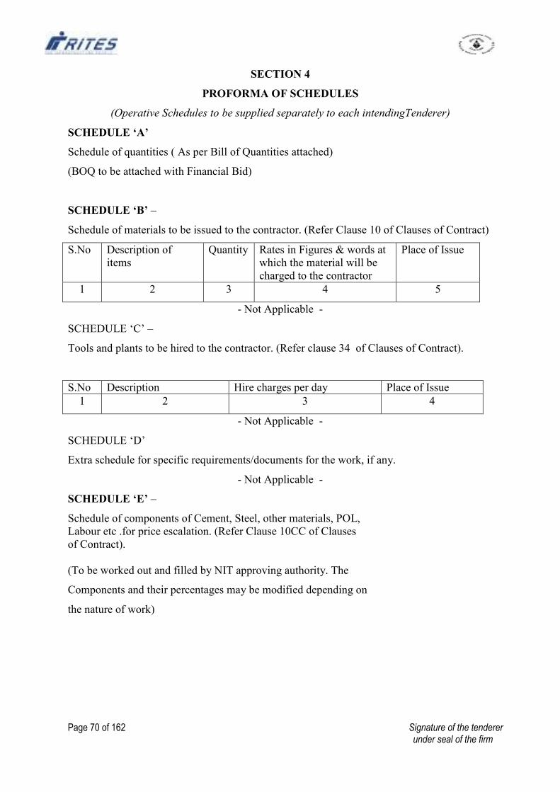
Page 70 of 162 Signature of the tenderer under seal of the firm
SECTION 4
PROFORMA OF SCHEDULES
(Operative Schedules to be supplied separately to each intendingTenderer)
SCHEDULE ‘A’
Schedule of quantities ( As per Bill of Quantities attached)
(BOQ to be attached with Financial Bid)
SCHEDULE ‘B’ –
Schedule of materials to be issued to the contractor. (Refer Clause 10 of Clauses of Contract)
S.No Description of
items
Quantity Rates in Figures & words at
which the material will be
charged to the contractor
Place of Issue
1 2 3 4 5
- Not Applicable -
SCHEDULE ‘C’ –
Tools and plants to be hired to the contractor. (Refer clause 34 of Clauses of Contract).
S.No Description Hire charges per day Place of Issue
1 2 3 4
- Not Applicable -
SCHEDULE ‘D’
Extra schedule for specific requirements/documents for the work, if any.
- Not Applicable -
SCHEDULE ‘E’ –
Schedule of components of Cement, Steel, other materials, POL,
Labour etc .for price escalation. (Refer Clause 10CC of Clauses
of Contract).
(To be worked out and filled by NIT approving authority. The
Components and their percentages may be modified depending on
the nature of work)
Page 71 of 162 Signature of the tenderer under seal of the firm
CLAUSE 10 CC : Not Applicable
Component of Cement (Xc)
expressed as percent of total value of work _______%
Component of steel (X5)
expressed as percent of total value of work ______%
Component of other materials (XM) (except cement & steel)
expressed as per cent of total value of work ______%
Component of labour (Y)
expressed as percent of total value of work _______%
Component of P.O.L (Z)
expressed as percent of total value of work _______%
______________
Total 100 %_
SCHEDULE ‘F’
Reference to General Conditions of Contract
Name of Work : Balance work of Laying & Linking of Railway track including
supply of ballast & other P. Way materials in connection with
construction management and arrangement of new Railway
Siding for rapid loading system at Junadih Siding of SECL at
Gevra, Dist. Korba (C.G).
Estimated cost of work Rs. 2,03,37,222/-
Earnest money : Rs. 2,03,500/-
Performance Guarantee (Ref. Clause 1) 5% of Tendered value.
Security Deposit: (Refer clause 1A) 5% of Tendered value
Notice Inviting Tender and Instruction to Tenderers
Officer inviting tender : Group General Manager (Projects),
RITES Ltd., Regional Project Office, Kolkata.
CONDITIONS OF CONTRACT
Definitions
2 (iv) Employer South Eastern Coalfields Limited (SECL)
2(v) Engineer-in-Charge Group General Manager (Projects), RITES Ltd.
2(vii) Accepting Authority Group General Manager (Projects)
2(ix) Percentage on cost of materials
and labour to cover all 15%
overheads and profits.
Page 72 of 162 Signature of the tenderer under seal of the firm
2(x) Standard Schedule of Rates RITES SOR for P. Way Works & SECR’s Unified
Standard Schedule of Rates 2010.
2(xiii) Date of commencement of work 15 days from the date of issue of LOA or the
first
date of handing over of site whichever is later
9 (a) (ii) General Conditions of Contract RITES General Conditions of Contract
July 2011 Edition as modified & corrected upto
C.S.No. 6 dated 12.05.2014.
CLAUSES OF CONTRACT
Clause 1
1 (i) Time allowed for submission of
P.G. from the date of issue of
Letter of Acceptance subject 15 days.
to maximum of 15 days
Maximum allowable extension
beyond the period provided in
(i) above subject to a maximum of 07 days.
7 days
Clause 2
Authority for fixing compensation under
Clause 2 Group General Manager (Projects), RITES Ltd.
for & on behalf of SECL.
Clause 2A
Whether Clause 2A shall be applicable NO
Clause 5
5.1 (a) Time allowed for execution of work 08 (Eight) months from the date
of
start
Date of start 15 days from the date of issue of
Letter of Acceptance or the first
Date of handing over of site
whichever is later
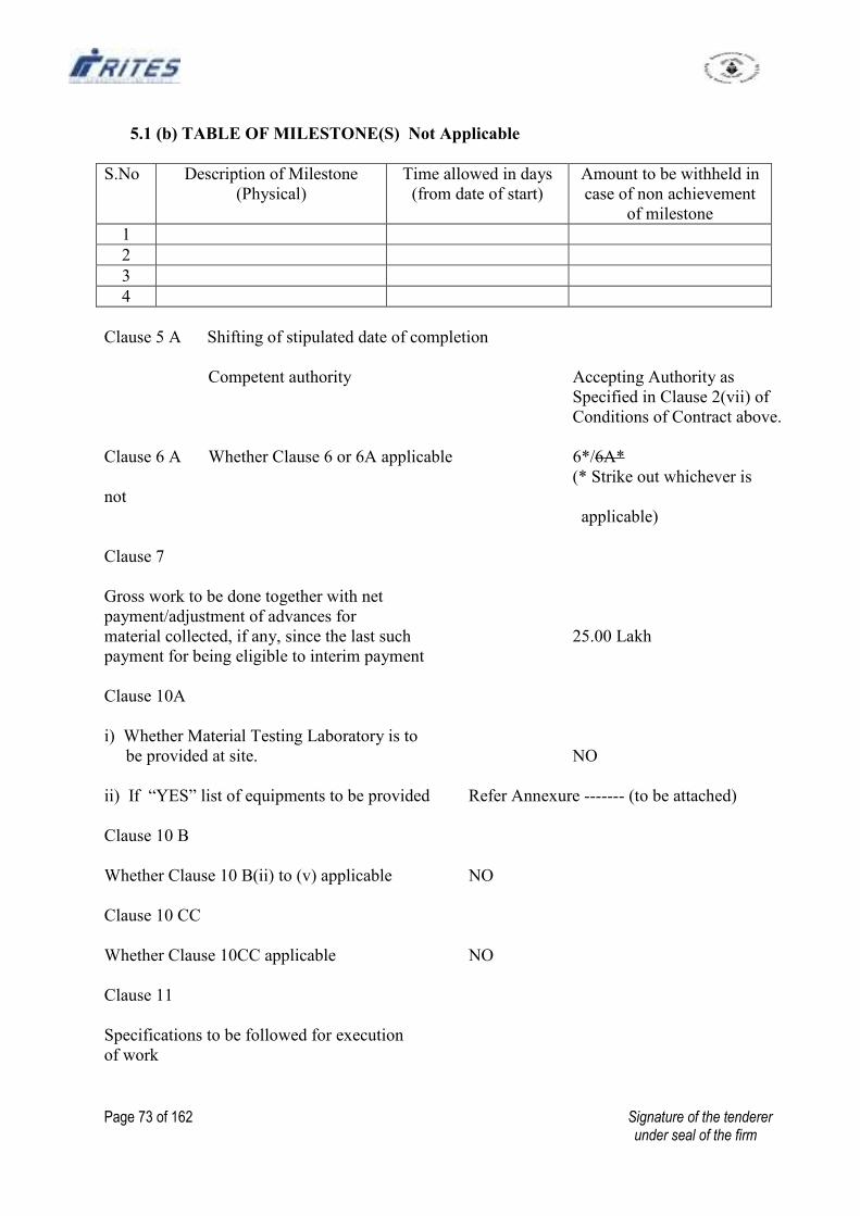
Page 73 of 162 Signature of the tenderer under seal of the firm
5.1 (b) TABLE OF MILESTONE(S) Not Applicable
S.No Description of Milestone
(Physical)
Time allowed in days
(from date of start)
Amount to be withheld in
case of non achievement
of milestone
1
2
3
4
Clause 5 A Shifting of stipulated date of completion
Competent authority Accepting Authority as
Specified in Clause 2(vii) of
Conditions of Contract above.
Clause 6 A Whether Clause 6 or 6A applicable 6*/6A*
(* Strike out whichever is
not
applicable)
Clause 7
Gross work to be done together with net
payment/adjustment of advances for
material collected, if any, since the last such 25.00 Lakh
payment for being eligible to interim payment
Clause 10A
i) Whether Material Testing Laboratory is to
be provided at site. NO
ii) If “YES” list of equipments to be provided Refer Annexure ------- (to be attached)
Clause 10 B
Whether Clause 10 B(ii) to (v) applicable NO
Clause 10 CC
Whether Clause 10CC applicable NO
Clause 11
Specifications to be followed for execution
of work
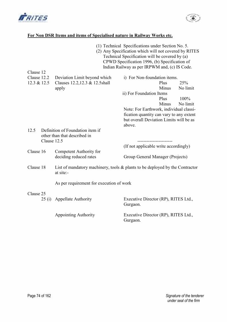
Page 74 of 162 Signature of the tenderer under seal of the firm
For Non DSR Items and items of Specialised nature in Railway Works etc.
(1) Technical Specifications under Section No. 5.
(2) Any Specification which will not covered by RITES
Technical Specification will be covered by (a)
CPWD Specification 1996, (b) Specification of
Indian Railway as per IRPWM and, (c) IS Code.
Clause 12
Clause 12.2 Deviation Limit beyond which i) For Non-foundation items.
12.3 & 12.5 Clauses 12.2,12.3 & 12.5shall Plus 25%
apply Minus No limit
ii) For Foundation Items
Plus 100%
Minus No limit
Note: For Earthwork, individual classi-
fication quantity can vary to any extent
but overall Deviation Limits will be as
above.
12.5 Definition of Foundation item if
other than that described in
Clause 12.5 -----------------------
(If not applicable write accordingly)
Clause 16 Competent Authority for
deciding reduced rates Group General Manager (Projects)
Clause 18 List of mandatory machinery, tools & plants to be deployed by the Contractor
at site:-
As per requirement for execution of work
Clause 25
25 (i) Appellate Authority Executive Director (RP), RITES Ltd.,
Gurgaon.
Appointing Authority Executive Director (RP), RITES Ltd.,
Gurgaon.
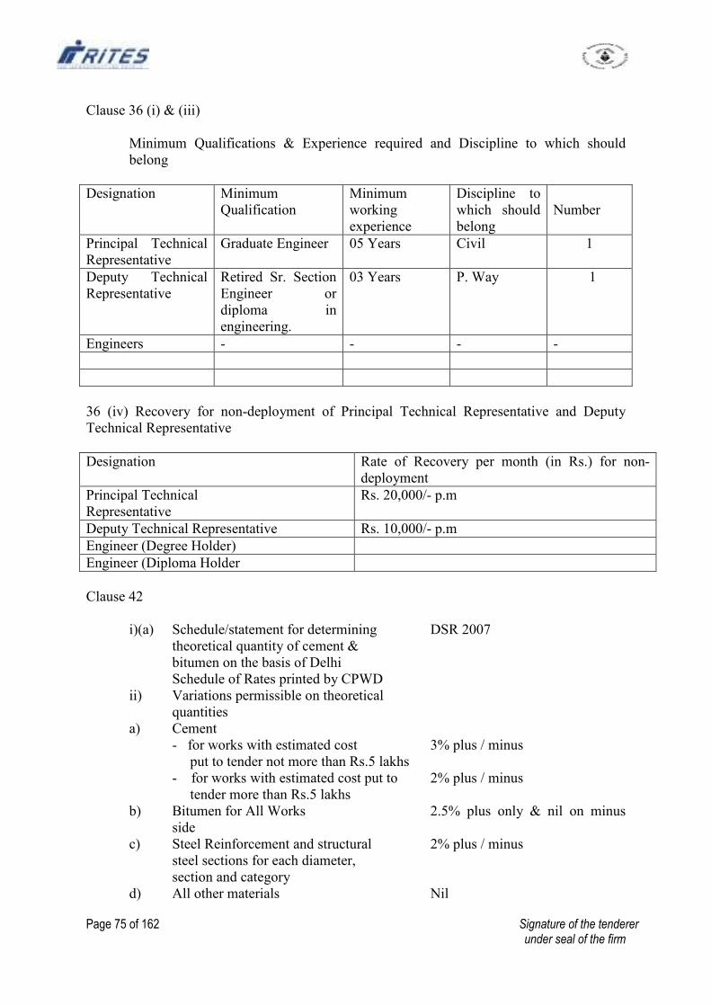
Page 75 of 162 Signature of the tenderer under seal of the firm
Clause 36 (i) & (iii)
Minimum Qualifications & Experience required and Discipline to which should
belong
Designation Minimum
Qualification
Minimum
working
experience
Discipline to
which should
belong
Number
Principal Technical
Representative
Graduate Engineer 05 Years Civil 1
Deputy Technical
Representative
Retired Sr. Section
Engineer or
diploma in
engineering.
03 Years P. Way 1
Engineers - - - -
36 (iv) Recovery for non-deployment of Principal Technical Representative and Deputy
Technical Representative
Designation Rate of Recovery per month (in Rs.) for non-
deployment
Principal Technical
Representative
Rs. 20,000/- p.m
Deputy Technical Representative Rs. 10,000/- p.m
Engineer (Degree Holder)
Engineer (Diploma Holder
Clause 42
i)(a) Schedule/statement for determining DSR 2007
theoretical quantity of cement &
bitumen on the basis of Delhi
Schedule of Rates printed by CPWD
ii) Variations permissible on theoretical
quantities
a) Cement
- for works with estimated cost 3% plus / minus
put to tender not more than Rs.5 lakhs
- for works with estimated cost put to 2% plus / minus
tender more than Rs.5 lakhs
b) Bitumen for All Works 2.5% plus only & nil on minus
side
c) Steel Reinforcement and structural 2% plus / minus
steel sections for each diameter,
section and category
d) All other materials Nil
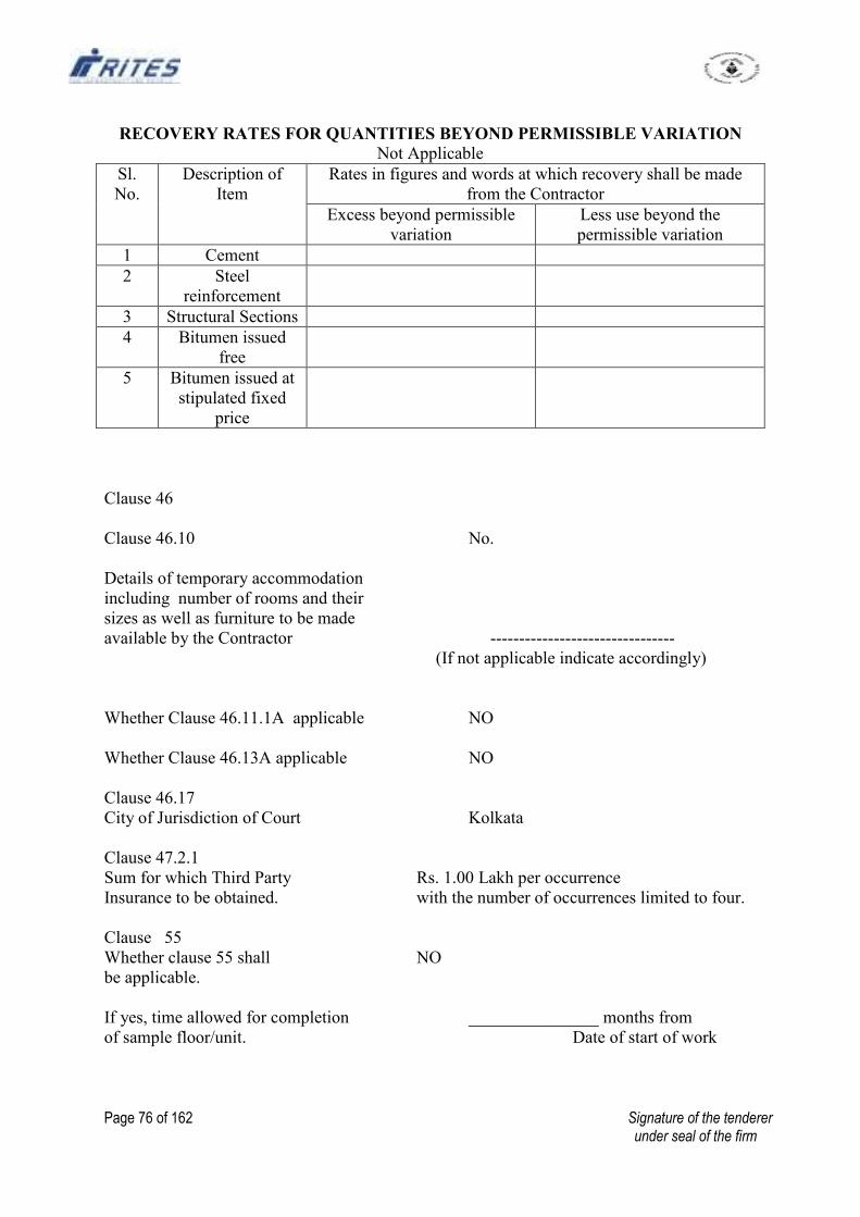
Page 76 of 162 Signature of the tenderer under seal of the firm
RECOVERY RATES FOR QUANTITIES BEYOND PERMISSIBLE VARIATION
Not Applicable
Sl.
No.
Description of
Item
Rates in figures and words at which recovery shall be made
from the Contractor
Excess beyond permissible
variation
Less use beyond the
permissible variation
1 Cement
2 Steel
reinforcement
3 Structural Sections
4 Bitumen issued
free
5 Bitumen issued at
stipulated fixed
price
Clause 46
Clause 46.10 No.
Details of temporary accommodation
including number of rooms and their
sizes as well as furniture to be made
available by the Contractor --------------------------------
(If not applicable indicate accordingly)
Whether Clause 46.11.1A applicable NO
Whether Clause 46.13A applicable NO
Clause 46.17
City of Jurisdiction of Court Kolkata
Clause 47.2.1
Sum for which Third Party Rs. 1.00 Lakh per occurrence
Insurance to be obtained. with the number of occurrences limited to four.
Clause 55
Whether clause 55 shall NO
be applicable.
If yes, time allowed for completion _______________ months from
of sample floor/unit. Date of start of work
Page 77 of 162 Signature of the tenderer under seal of the firm
Section - 5
TECHNICAL SPECIFICATIONS
Page 78 of 162 Signature of the tenderer under seal of the firm
SECTION 5
TECHNICAL SPECIFICATIONS
1- Technical Specifications for Earthwork and blanketing materials
in Railway Formation
1.0 GENERAL
1.1 The Technical Specifications to be followed for Earthwork in Railway Formation
including in Cuttings and Embankments shall be as stipulated in enclosed Annexure
A. In those Specifications, wherever there is reference to approval by Railway, it
should be replaced by approval by RITES/ Engineer-in-charge.
1.1.1 The Specifications at Annexure A should be read in conjunction with the Schedule
(Bill) of Quantities. Where there is conflict between the provisions in Annexure A
and in BOQ, the provisions in BOQ shall prevail.
ANNEXURE A
EARTHWORK IN RAILWAY FORMATION
1.1 EARTHWORK - GENERAL
1.1.1 RDSO Guidelines: For survey, design and execution of earthwork in railway
formations, RDSO has issued detailed guidelines as “Guidelines for Earthwork in
Railway Projects – Guideline No. GE: G-1” in July 2003. These Guidelines including
their subsequent amended/revised versions, if any, shall apply to execution of
earthwork in railway formations. These guidelines or their amended/revised versions
have subsequently been referred to in this chapter as ‘RDSO Guidelines’. In case of
any conflict between provisions of this chapter and those of RDSO Guidelines, the
latter shall prevail.
1.1.2 Site Clearance: - Before work is started, the whole area between the toes of banks or
tops of cuttings plus 1m additional width on both sides shall be properly and
effectively cleared by the contractor of all vegetation, small trees of girth upto 30 cm
(measured at a height of 1m above ground level), roots, bushes, heavy grass etc; The
Contractor shall also clear the site of all buildings, abandoned structures etc as
directed by the Engineer, for which extra payment will be made. The Contractor shall
arrange removal of rubbish and other excavated material excluding earth upto a
distance of 100 metres outside the periphery of the area under site clearance. Top soil
obtained from site clearance as well as top layer of borrow pits which is rich in
organic content and suitable for plant growth, if directed by the Engineer, may be
stored for covering slopes of embankment and cuttings after construction. High
portions of the ground shall be cut down and hollow depressions, if any, filled up
with suitable excavated soil duly compacted and the ground dressed and levelled.
The work of this nature will be covered by the initial rate for earth work, unless stated
to the contrary in the agreement.
1.1.2.1 Trees of girth over 30 cm, measured at a height of 1m above ground level, shall be
considered as large trees. Cutting down of large trees shall be paid extra at the rate
specified in the Schedule of Rates. The rate shall include lopping of branches,
Page 79 of 162 Signature of the tenderer under seal of the firm
trimming, removal from and clearing of site when stumps are grubbed up in addition.
Large trees shall not be cut without specific orders from the Engineer. As few trees
shall be cut as is absolutely necessary for the execution of work. The roots of trees
and saplings shall be removed to a depth of 60 cm below ground level or 30 cm
below formation level or 15 cm below subgrade level, whichever is lower. All holes
or hollows formed due to removal of roots shall be filled up with earth rammed and
levelled. Trees, shrubs, poles, fences, signs, monuments, pipe lines, cable, etc
adjacent to the area which are not required to be disturbed during site clearance shall
be properly protected by the contractor at his own cost and nothing extra shall be
payable.
1.1.2.2 Any trees cut down or building materials released from dismantling of structures shall
be stacked by the contractor within a distance of 100 metres outside the periphery of
the area under site clearance as per instructions of the Engineer. The contractor shall
have no claim to the trees or other material removed during site clearance and the
same shall be the property of the Railway.
1.1.3 DATA AND SETTING OUT :
(a) Initial Data
At the commencement of work, the Engineer In charge shall give to the
contractor the following data/ guidance.
(I) Concrete centre line pillars fixed on the alignment at intervals of 250m,
Pucca level bench marks fixed along the alignment, about 30 m away from the
centre line at intervals of 500m. These bench marks shall have been connected by
leveling to available GTS bench marks and the reduced level of each shall be
communicated.
(ii) Longitudinal section of the proposed formation to scale 1:2500 horizontal and
1:500 vertical with the existing ground level and the proposed formation level
marked at intervals of 50m along the alignment and with the location of each
curve, bridge, culvert, and level crossing on the entire alignment indicated.
(iii)Existing ground level would be jointly recorded by the Engineer-in-Charge or his
representative and the contractor or his representative by taking cross section at an
interval of 25m or as suitable so as to produce the general existing ground profile.
The Contractor will have to sign the level book as a token of acceptance of the
level and it will form the original record for payment.
(iv) Ground levels recorded as above would be plotted to a natural scale 1:100 at a
subsequent date and desired profile of bank/cutting would also be plotted on it.
This will also be signed by contractor and would be the basis for the final payment
of earth work to be done.
(v) The contractor shall be responsible for subsequent preservation of all the above
mentioned pillars and drawings and shall pay for the cost of their replacement, if
necessary.
Page 80 of 162 Signature of the tenderer under seal of the firm
(b) Setting out :
Before commencement of earth work, the Contractor shall demarcate with a furrow,
at least 20 cm wide and 15 cm deep, at 50 cms from the the toes of slopes of banks
and outside limits of tops of cuttings on both sides of centre line and the boundaries
of the bottom and top of the borrow pits. The “ dag belling” is to be maintained and
renewed when necessary, throughout the duration of earth work. The cost of this is
included in the rate for earth work.
Concrete pillars of 30 cms square at 50 cms away from and on both sides of the toe of
the bank / top of cutting at each cross section would be constructed and maintained by
the contractor at his own cost as a part of the setting out works. These concrete
pillars should be embedded to a depth of 50 cms. No extra payment on this account is
permissible. He will also provide and maintain and maintain templates, burjies,
reference pillars etc and shall take all necessary precautions to prevent these being
removed, altered or disturbed and will be responsible for the consequence of such
removal, alteration or disturbance and for their efficient reinstatement. No extra
payment will be made on this account.
(b) Profiles:
In accordance with cross sections supplied, the Contractor shall at his own expense
provide all stakes, bamboos, strings, pegs and labour for setting out profiles at every
25m or as directed for correct execution of the work. This will include provision of
side drains and catch water drains as necessary in cutting and / or as marked in the
cross sections supplied to the Contractor. The top of formation shall invariably have
cross slopes of 1:30.
1.1.4 Mechanised construction of Earthwork: Manual methods of construction can not
achieve the desired quality of earthwork. Therefore in all projects, it is necessary to
deploy mechanised equipments such as earthmovers, dozers, hydraulic excavators,
motor graders, scrapers, dumpers, mobile water sprinklers, vibratory rollers,
sheepfoot rollers etc. so that quality of work meets laid down standards.
1.1.5 Maintenance: Banks and cuttings are to be correctly dressed and finished in profile
with slopes as specified in each case. Where gullies or water-cuts commence to form
on the slopes of embankments or cuttings, the erosion is to be checked as early as
practicable and made good with suitable material well rammed into place. Where a
gully or water-cut has not been checked at its commencement, it may be advisable to
cut it out or step it before filling it in, and to further protect the place by turfing,
pitching or other means as may be ordered by the Engineer. Work, before being
finally paid for, is to be checked by the Engineer as having been correctly brought up,
or carried down, to the proper level and to be otherwise complete in all respects in
accordance with the specifications.
1.1.5.1 As soon as the work has been satisfactorily completed, the Engineer shall issue a
certificate of completion in respect of the work as specified in relevant Clause of the
General Conditions of Contract. Unless otherwise specified in the Tender conditions,
the contractor shall maintain the banks / cuttings, for a period of Twelve months from
the date of completion of work as indicated in the certificate of completion. The
Page 81 of 162 Signature of the tenderer under seal of the firm
contractor shall be responsible for the handing over of the banks/cuttings to the
Railway in proper condition, and, where necessary, for their restoration to such
condition, at the end of the maintenance period. Until then, the contractor is
responsible for all losses due to subsidence, wastage or guttering due to rain, wind,
wear, wash or from any other cause whatsoever, and he shall have no claim for any
extra work or payment on this account.
1.1.6 Spoil from cutting to bank:- Up to the initial lead specified in the BOQ item,
material from each end of every cutting – subject to its suitability for use in railway
embankment- shall be led forward into the adjoining bank as a matter of course, and
the rate to be paid for such material shall be the rate for cutting only. The Engineer
shall specify in each case from what point in each cutting to what point in the
adjoining bank, spoil shall be led out, payment being made only for the excess lead
over and above the initial lead included in the rate for cutting. The Engineer can
modify these limits at any stage of the work and all such changes shall be binding on
the contractor without any claim for any extra payment on this account. Dressing and
compaction of the bank will, however, be paid for in addition.
1.1.7 Classification of soils:- The classification of soil/rock met with in executing the
work, if not made by the Engineer, shall be made by the his representative authorized
by him for this purpose subject to the approval and final decision of the Engineer,.
The rates to be paid to the contractor in his bills shall be based on these
classifications.
Earth work shall be classified under the following heads:-
1.1.7.1 All kinds of Soils:- Generally any strata such as sand, gravel, loam, clay, mud, black
cotton, moorum, shingle, river or nallah bed boulders, soling of roads, paths etc.
macadam surface of any description, lime concrete, mud concrete and their mixtures
which for excavation yields to the application of picks, shovels, jumpers, scarifiers,
ripper and other manual digging implements.
1.1.7.2 Ordinary Rock: Generally any rock which can be excavated by splitting with
crowbars or picks and does not require blasting, wedging or similar means for
excavation, such as lime stone, sand stone, hard laterite, hard conglomerate and
unreinforced cement concrete below ground level. If required light blasting may be
resorted to, for loosening the materials but this will not in any way entitle the material
to be classified as ‘Hard rock’.
1.1.7.3 Hard Rock (Requiring Blasting):- Generally any rock or boulder for the excavation
of which blasting is required Such as granite, quartzite, basalt, reinforced cement
concrete below ground level and the like.
1.1.7.4 Hard Rock (Blasting Prohibited):- Hard rock requiring blasting as described under
sub para 1.1.7.3, but where blasting is prohibited for any reason and excavation has
to be carried out by chiselling, wedging or any other agreed method.
1.1.8 Measurements:- Cutting and banks are to be excavated and made up neatly to the
lines shown in the cross section as per approved construction drawing. No payment
will be made for excess work done outside these lines except when such work is so
Page 82 of 162 Signature of the tenderer under seal of the firm
ordered in writing by the Engineer. However, in case of embankments, extra width
constructed, as per Para 1.2.5.6, to ensure proper rolling and compaction which is
subsequently cut and dressed to avoid loose earth on the slopes shall not be paid for.
1.1.8.1 Should the Engineer so desire, he may, at any stage of the work, order the Contractor
to increase or reduce the slopes of any cutting or bank or alter the formation level, in
which case the amount of work actually done will be paid for in accordance with the
specifications and the Schedule of Rates.
1.1.8.2 Unless otherwise specified the rate for Earth work is inclusive of an initial lead and
lift as specified in the BOQ...
1.1.8.3 Additional lead for the purpose of payment will be measured from the centre of
gravity of excavation to the centre of gravity of the bank or spoil heap, and shall be
measured along the shortest practicable route and not necessarily the route actually
taken.
1.1.8.4 Where initial lift is specified, additional lift for the purpose of payment will be
estimated by dividing the cross section of the bank or cutting into successive stages of
1.5m high or deep respectively from the natural ground level and only the quantity
contained in each strip shall be paid for at the rate appertaining to its height or depth
above or below the natural ground level, respectively. Lift from the borrow-pit to the
ground level or from ground level to the spoil bank shall not be taken into account in
any payment for lift unless the depth of the borrow- pit or the height of the spoil bank
has been made in excess of 1.5m under instructions from the Engineer, and in such
cases, only the portion of the borrow-pit below 1.5m depth or of the spoil bank above
1.5m height as measured from the natural ground level, shall be, measured separately
for payment of lift on the same basis as for cuttings or banks respectively.
1.1.8.5 For the purpose of above para, the natural ground level shall be reckoned as that
obtaining at the toe of the bank nearest to borrow pits or at toe of spoil bank nearest
to the cutting as the case may be. No payment shall be made for any lift from the
ground level at the borrow pit to that at the bank, or from the ground level at the
cutting to that at the spoil bank, where such lift is inherent in the lead on account of
natural ground slope and no obvious act of lifting is involved, in the opinion of the
Engineer. Obvious lifts such as involved in crossing of existing pits or banks, which
cannot be avoided, will be measured and taken into account for payment. In such
cases, the additional lift thus measured shall be taken into account in fixing the
successive stage of 1.5m, whether in the bank or in the cutting. In sidelong ground
where borrow-pits or spoil banks, as the case may be, are made on both sides, any
payment for lift shall be a matter of special agreement.
1.1.8.6 For purpose of payment, cuttings shall be assumed to be composed of such soil / rock
only, as stand exposed on both or one side of the finished cuttings, depending upon
whether the cutting is box type or one sided on a transversely sloping ground. The
content of each type of soil/rock thus assigned to any cross section shall be
determined as indicated below. It is to be noted that no portion of cutting will be
payable for any such type of soil/rock as is not exhibited on the finished side slope,
where the side slope exists.
Page 83 of 162 Signature of the tenderer under seal of the firm
(a) For box type cutting:- The centre line of the alignment will be marked vertically
on the cross section and the content of each type of soil/rock will be determined by
computing the area of the strip, formed by joining the points, which form the
extremity of occurrence of the particular soil on the finished side slope of cutting, by
straight horizontal lines terminating on the centre line. Figure No.1.1 is illustrative of
the manner in which payment is to be made.
(b) For one sided cutting on a transversely sloping ground:- Content of each type
of soil/rock will be determined by computing the area of the strip, formed by joining
the points, which form the extremity of occurrence of the particular soil on the
finished side slope of the cutting, by straight lines to the zero point. Figure No.1.2 is
illustrative of the manner in which the payment for the cutting will be made.
(c) For widening of existing cuttings for one or more lines where the existing
cutting slope disappears and a fresh slope stands:- Before undertaking widening
of the cutting, pre-classification of the existing cutting slope (which will disappear)
should be done after clearing and cleaning the surface and the strata met marked on
the cross-section sheets. After completion of the work various strata as stand exposed
on the new finished slope of the cutting shall again be marked on the cross-sections.
Then the demarcation points of adjacent strata as determined by classification of the
existing slope and the final slope should be joined as shown in Figure No.1.3.
The cross-sectional areas for different strata may be worked out and quantities
payable
classification-wise assessed accordingly.
(c) For extension to the existing cutting where no fresh cutting slope is available after work:- Before execution of the work pre-classification of the existing
cutting slope which will not be finally available, should be done and recorded in
the initial cross-section. Figure No.1.4 is illustrative of the manner in which the
payment for the cutting is to be made for soil of different classifications.
1.1.8.7 Classification in the above manner shall be made only at such points where the cross
sections giving the ground profile have been recorded. The classification as recorded
in the above manner in case of cuttings shall be signed by the contractor in token of
his acceptance. The classification as recorded by the Authorized representative of the
Engineer in the above cases for cuttings is subject to confirmation by the Engineer,
whose decision shall be final and binding on the contractor. Where there is
disagreement between the Contractor and the Authorized representative of the
Engineer on classification of soil, payment shall be effected “on account” as per
lower classification as made by the Authorised representative of the Engineer.
Payment for extra at the rate for higher classification shall be made after final
decision by the Engineer on the admissibility of the Contractor’s claim for higher
classification.
Page 84 of 162 Signature of the tenderer under seal of the firm
1.1.8.8 In computing the quantity of earth work in cuttings and side drains, no cognizance
will be taken of the additional excavation, which may be necessitated during the
progress of the work due to the presence of boulders or other material, and payment
will only be made for the quantity as per cross sections required to be provided.
1.1.8.9 Where cutting spoil is utilised for making the bank, stones over 75mm size, which are
not to be used in the bank, shall be stacked separately at a site to be indicated by the
Engineer. To determine the quantity of cutting spoil led out for making the bank, the
sectional quantity of the cutting shall be reduced by the volume of stones and
boulders stacked outside, which will be arrived at by deducting 50% for voids from
the stack measurements of these stones and boulders. The stacking of these stones
and boulders, including initial lead and lift specified in the item, is covered by the
initial rate of Earth work.
1.1.8.10 It must be clearly understood that the Contract rates are intended to cover the
full cost of finished work as per approved drawings or as directed by the Engineer
with nothing extra payable for work carried out in excess of the requirements. Banks
and cuttings are to be carefully dressed to formation with such slopes as may be
specified in each case. The payment for the quantity of earth work in cutting / bank
shall normally be made on cross sectional measurements. The existing ground / bank
profile shall be taken and plotted by the Authorised representative of the Engineer in
the presence of contractor or his authorized agent before commencement of the work.
The profile of the bank or the cutting required to be provided shall also be plotted on
the same sheets. The levels and cross sections shall be signed by both the Authorised
representative of the Engineer and the contractor / his authorized agent. (The profiles
of the bank or cutting as required to be provided are for the guidance of the contractor
and not for the purpose of measurements).
The profiles of the finished and plotted bank/ cutting shall like-wise be taken in the
presence of the contractor or his authorised agent and super-imposed on the original
ground profile. These profiles are to be taken at locations as directed by the Engineer,
at least at 25m intervals on straight and every 15m on Curves with radii sharper than
600m and at extra locations in special cases such as irregular or side long ground etc.
The gross volume of earth work shall be calculated from the original and finished
profile of the bank/ cutting.
As it may, at times, be difficult to measure by means of cross sections the quantity of
rock excavated by blasting or chiselling, owing to its irregular configuration or
intermixture with other materials, the quantity of rock may be measured after stacking
the excavated rock spoil. The same procedure also applies to any other type of
soil/rock, which requires to be measured separately from the material constituting the
bulk of the spoil. In all such cases, the payable quantity of the stacked material is to
be arrived at by making suitable deductions for voids from the measured cubical
contents of the stacks as specified below:-
Type of soil stacked Deduction
(a) Rock spoil of different sizes 30 per cent
(b) Sandy materials 7 ½ per cent
(c) Black cotton soil 20 per cent
Page 85 of 162 Signature of the tenderer under seal of the firm
(d) Other soils, including coal ashes 15 per cent
To facilitate measurement, all stacks to be measured shall be made rectangular in plan
and of uniform height, on level ground or ground levelled for this purpose. The
stacking of spoil shall be done in a compact manner to the satisfaction of the
Engineer. The rates provided shall include all charges on account of such stacking as
well as any lead or lift, as also the re-stacking of stacks or portions of stacks which
the Engineer considers, in his sole discretion, as not properly stacked.
Where earthwork is required to be done from borrowpits for repairs to bank to make
up cess, to fill raincuts etc, the payment for such earthwork will be effected on
borrow pit measurements.
As far as possible spoils from cuttings fit for embankment shall be used to make up
the bank. If however, this is found to be uneconomical due to excessive lead or lift,
or if sufficient quantity of good earth fit for embankment is not available from the
source of cut spoils contractor’s earth approved by Engineer or earth from borrow pits
in railway land as directed by Engineer shall be utilised. As far as possible each
stretch of bank should be made of earth from only one source so as to avoid mix up.
If however, this is not possible due to exigencies of work, earth from one source
should be utilised first and compaction done before earth from the next source is
allowed to be dumped. Initial cross section of bank and cross section after
compaction of earth from each of the sources should be taken. Based on the cross
sectional areas, the gross quantity of earth work in embankment executed by utilising
the earth from different sources shall be determined
Final measurements shall be taken only after the bank/ cutting has been completed to
the required profile as directed by the Engineer irrespective of the period of
completion and number of monsoons that may pass during execution.
1.1.8.11 Where, for any reason at the discretion of the Engineer, borrow-pit measurements
are resorted to, all matams and roads and excess earth work, such as bulges in the
slopes of the banks, shall be excluded from the measurements.
1.1.8.12 Nothing extra shall be paid for :-
i)Excavation for insertion of planking and strutting.
ii) Removing slips or falls in excavations
ii) Bailing out water in excavations from rains, ordinary springs not requiring
pumping etc.
(Note:- Pumping out water caused by powerful springs, tidal or river seepage,
broken water mains or drains and the like, shall be paid separately if provided for
in the Agreement)
iii) Unauthorised battering or benching of excavations.
iv) Forming steps in sides of deep excavations and their removal after
measurements.
v) Protective measures for protection against risk of accidents to the public due to
open excavation.
vi) Protective measures / precautions taken to avoid damage to existing Signal /
Electrical / Telecom / other Miscellaneous Cables, Pipes, installations etc.
Page 86 of 162 Signature of the tenderer under seal of the firm
1.1.8.13 On account payment
1.1.8.13.1 Running on account payments will normally be made only for such length of
banks as in the opinion of the Engineer-in-Charge have been finally executed in terms
of the conditions of contract. On account payments may however he made at the
discretion of the Engineer-in-Charge if uncompleted bank is high or there are other
circumstances which may result in heavy investment on the part of the contractor,
before he is able to complete a stretch of bank in all respect. Such on account
payment will be made to the extent of only 90% of the total quantity of earthwork.
Contractor shall submit royalty clearance certificate along with Running Account
bill, if the agency fails to submit the royalty clearance certificate, the required amount
will be deducted as per extant Govt. rule, from his bill and will be deposited with the
concerned dept.
1.1.9 Dressing Surface:-
1.1.9.1 This specification is applicable to Surface dressing executed as a separate work for
purposes other than earthwork for embankment or cutting. In case of earthwork for
embankment or cutting, provisions of Para 1.1.2 will apply and the surface dressing
will be covered by the initial rate of earthwork unless stated to the contrary in the
Agreement. This specification shall also be applicable only to earthwork involving
soil.
1.1.9.2 The terms “Dressing Surface” shall be taken to mean the cutting down of high portion
of a specified area of ground and using the excavated earth to fill up the hollows and
the depressions. The maximum depth of excavation or filling shall be restricted to 15
cms.
1.1.9.3 The levels to which the ground is to be dressed shall be such that the quantity filled is
nearly equal to the quantity cut and the finished surface is even and tidy with such
slopes as may be necessary for proper drainage. Before the work is commenced the
proposed levels shall be set up at regular intervals both for the cuts and for the fills,
by suitable means as directed by the Engineer and these shall be got checked and
approved by him.
1.1.9.4 Unless otherwise provided for in the Contract, the rates shall be inclusive of removal
of rubbish upto a distance of 50m outside the periphery of the area cleared.
1.2 EARTHWORK IN EMBANKMENTS
1.2.1 Profiles:- Profiles for banks shall be set out where every cross section has been
taken. These profiles shall be set up atleast every 25m on the straight and every 15m
on curves with radii shorter than 600m. Profiles shall also be set up at any additional
places if ordered by the Engineer.
1.2.2 Formation Width:- The formation widths are to be as shown in the drawings.
1.2.3 Side Slopes:- The side slopes will ordinarily be as shown in the drawing, but the
Engineer or his Authorised representative may, by order in writing, vary this slope to
suit local conditions.
1.2.4 Selection of Earth:- Fill material proposed to be used, either from railway land or
from outside shall be assessed for its suitability at contractor’s expense, in accordance
with RDSO Guidelines. The contractor shall get the prior approval of the Engineer for
Page 87 of 162 Signature of the tenderer under seal of the firm
the quality of the fill material. Soil groups falling under the classifications GB, GW,
GC, GM, GP, SB, SW and SC under IS Code 1498are generally considered suitable.
1.2.5 Execution of Earthwork:
1.2.5.1 The spreading of material in layers of desired thickness over the entire width of
embankment should be done by mechanical means and finished by a motor grader.
The motor grader blade shall have hydraulic control suitable for initial adjustment and
maintain the same so as to achieve the slope and grade.
1.2.5.2 Thickness of layer is to be decided in accordance with RDSO Guidelines. However,
as a good practice thickness of layer should be generally kept as 300mm for fill
material and 250mm for blanket material in loose state before compaction.
1.2.5.3 Efforts, in accordance with RDSO Guidelines, should be made to keep moisture
content level of the soil in the range of OMC + 2% at the time of compaction.
1.2.5.4 The rate of progress should be, as far as possible, uniform so that the work is
completed to final level almost at the same time.
1.2.5.5 The rolling for compaction of fill material should commence from edges towards
center with minimum overlap of 200mm between each run of the roller. In final pass,
roller should simply move over the surface without vibration so that top surface is
properly finished.
1.2.5.6 Extra bank width of 500mm on either side shall be rolled to ensure proper compaction
at the edges. The extra soil would be cut and dressed to avoid any loose earth at the
slopes. This should preferably be done with help of grade cutter. In case of widening
of embankments the extra width to be rolled shall be 300mm instead of 500mm.
1.2.5.7 At the end of the working day, fill material should not be left uncompacted. Care
should be taken during rolling to avoid ponding on formation.
1.2.5.8 During construction of formation, there may be rainfall to the extent that rain cuts
may develop on the surface of formation due to erosion of soil. Care should be taken
that these rain cuts are not allowed to develop wide and deep otherwise these
locations will remain weak spots.
1.2.5.9 Top of the formation should be finished to cross slope as provided in contract
drawings.
1.2.5.10 Once the top surface of the formation has been finished to proper slope and
level, movement of material vehicle for transportation of ballast, sleepers etc. should
be avoided since these movements will cause development of unevenness, ruts on the
surface which will accumulate water and weaken the formation.
1.2.5.11 At locations where the water table is high and the fill soil is fine-grained, it
may be desirable to provide a granular layer of about 30 cm thickness at the base,
above subsoil across the full width of formation. This work will be carried out if
directed by the Engineer for which extra rate will be paid.
Page 88 of 162 Signature of the tenderer under seal of the firm
1.2.5.12 At places where embankment material are not conducive to plant growth, top
soil obtained from site clearance as well as top layer of borrowpits which is rich in
organic content and suitable for plant growth, may be stored for covering slopes of
embankment and cuttings after construction or other disturbed areas, where
revegetation is required as far as practicable.
1.2.5.13 In conversion / doubling / rehabilitation projects, suitable benching of existing
slope, in steps 30cm in height and 60cm deep, shall be cut in the existing bank before
any new earth is placed, to form a bond between the new and old earth work.. It
should be ensured that there is no humus material left on the benched slope. Care
needs to be taken to avoid entry of rainwater into the formation from this weak
junction, otherwise this would result in development of weak formation, slope failure,
maintenance problem due to uneven settlement etc.
1.2.5.14 Similar benching is to be provided in side-long ground of which the slope at
right angles to the alignment of the banks is 3 Horizontal to 1 vertical or steeper or if
ordered by the Engineer. The benching in side long ground will not be separately
measured or paid for, but is deemed to be covered by the initial rate for earth work.
1.2.6 Embankment in Water-logged ground etc:- When embankments are to be carried
across water-logged or swampy ground or to be made in soil which requires special
protective measures, it rests with the Contractor in all such cases to bring these facts
to the notice of the Engineer concerned who will direct on the methods to be adopted
and the rates to be paid, and will arrange for a special agreement for the same if
necessary.
1.2.7 Borrow Pits:- The Engineer concerned will direct from where material is to be
obtained As far as possible, Bank should be made of homogeneous material with no
mix of rubble or boulders with soil. In case of land provided by the Employer, no
excavation for borrow pits shall be made within 2m of the limits of the acquired land.
Borrow pits shall not be dug close to level crossings, bridges or culverts, telegraph
poles, electric poles, or close to inhabited areas, unless they can be properly drained
to prevent water stagnating. Borrow pits within station limits shall be avoided as far
as possible. The earth is to be excavated and thrown to such width, depth and height
and in such places as may be from time to time decided.
1.2.7.1 During excavation, the contractor shall take particular care to avoid damage to drains,
water mains, cables or other underground work. Should any damage be caused, the
Engineer shall be notified immediately and the damage shall be made good at the
contractor’s expense.
1.2.7.2 Where Earthwork is to be carried out within Railway land and where borrowing of
Earth from Railway land is agreed to by the Railway as confirmed in writing by the
Engineer-in-charge, Borrow pits shall be excavated within the limits of railway land
as directed by the Engineer. The pits must be rectangular or conform to the land
boundaries. The sides of the pits next to the toe of the bank are to be sloped down at
2:1, and elsewhere at a slope of 1:1 unless otherwise directed by the Engineer. Any
pits wrongly excavated shall be refilled by the contractor at his own cost, and in such
a manner as the Engineer directs.
Page 89 of 162 Signature of the tenderer under seal of the firm
1.2.7.3 Borrow pits are not to be made of uneven depth but the whole area of each pit is to be
neatly excavated to the same level. The outer or the most distant half of the
borrowpits is to be excavated first, so that in the event of the pits being flooded by
rain, there will still be ground available for work.
1.2.7.4 A berm 15m wide is to be left untouched initially at every 80m between edges of
borrowpits, and is not to be encroached upon for any excavation except under the
instructions of the Engineer. If it is necessary for drainage purposes to cut through
the berm, the channel will be made on the side remote from the Bank.
1.2.7.5 In side long ground, the borrow pits are to be dug on the upper side of the bank, and
are to be continuous to serve as catch water drains; and, if so ordered, the contractor
shall get the earth for the bank exclusively from such pits till the catch water drain is
complete to the required length, section and level as prescribed by the Engineer.
1.2.7.6 When doing repair work to banks it is absolutely essential that diagonal bunds be
kept, when digging fresh borrow-pits in the old ones, as a precautionary measure for
correct assessment of the work. Diagonal bunds are also to be kept in borrow-pits for
new works where payments are to be made on borrow-pit measurements. When
doing earthwork repairs, Authorised representative of the Engineer should bear this
point in mind and refuse to measure up any pit in which a diagonal bund has not been
kept. For repair works it would save a large amount of unnecessary detailed
measurements if all pits were excavated to a uniform size as far as practicable.
1.2.8 Stream diversions:- When it has been decided to divert a stream adjoining the bank,
the excavation for this work is to be undertaken and completed before any borrow pit
work is done at site and all earth from such diversion is to be put into the main bank,
if so ordered. If earth excavated from the drain is led into the bank, payment will
only be made for the quantity excavated including lead and lift if any and not for both
cut and fill. In excavating for diversion of stream, care must be exercised by the
Engineer that such diversion does not start a land slip.
1.2.9 Bank executed manually:- All railway embankments shall be constructed only by
mechanical means in accordance with RDSO Guidelines. Other embankments, when
executed manually, shall be made in successive layers, of not more than 30cm
uncompacted depth, over the whole width. The subsequent layer shall be started only
when the previous layer has been completed for a length not less than 30m along the
embankment. All large clods shall be broken up in the borrow pits or bank by labour
specially detailed for this work. This shall be strictly ensured.
1.2.10 Backing to bridges:- In carrying embankments over a bridge or a culvert intended to
be covered by the work, the earth work shall be brought up evenly on both sides of
the structure so that the pressure may be equalised. In filling in the approaches of a
bridge, or the spandrels between small arches, the earth filling shall be raised
simultaneously with the wing walls in the former case and with the face walls in the
latter, in order that the filling may be well trodden down under the feet of the
labourers; and in filling in foundations and backing to revetments, the earth work
shall similarly be brought up level as the masonry proceeds. Filling for the backing
of bridges or culverts will conform to specifications under Para 1.6.3 or as ordered
by the Engineer.
Page 90 of 162 Signature of the tenderer under seal of the firm
1.2.11 Dressing:- After completion of earth work the slopes shall be neatly dressed to the
correct profiles, and shall be made up where required during the maintenance period.
The top should be neatly dressed off sloping at an inclination of 1 in 30 either side
from the centre line unless otherwise specified in the drawings.
1.2.12 Turfing:- Turfing of banks shall be done during the monsoon season, preferably after
a heavy shower, when it can be ensured that the bank slopes will remain wet for a
long time after planting the grass. Turfing shall be paid for separately. Turfing shall
not be commenced without the prior written permission of the Engineer.
1.2.12.1Before turfing is commenced, the side slopes are to be dressed to the specified
section. This dressing is included in the initial rate for earth work, and should a
contractor stop work before dressing the bank, he shall be debited with the estimated
cost of the dressing to be done by another contractor or departmental labour, as
decided by the Engineer. Where the slope is already consolidated, it should be
loosened for a depth of about 4 cms before the sods are laid.
1.2.12.2 Turfing shall consist of sods, not less than 10 cm thick and 20 cm square well beaten
into the bank till they get a proper hold and form a level and compact mat. The
contractor shall be responsible for watering where necessary to ensure that the turf
grows properly; and in the event of it not doing so, he will returf such parts as have
not grown, at his own cost. The turfing shall be measured and taken over only after
the grass has rooted well and has formed a sufficiently dense growth over the earth
slopes.
1.2.12.3 Turfing of side slopes of cuttings if ordered by the Engineer shall be carried out in a
manner similar to Turfing of bank.
1.2.13 Sarkanda or similar type of planting on bank slopes:- Where Sarkanda is planted
on bank slopes, the minimum distance centre to centre in rows shall be 75 cm in
either direction. The plantation in adjacent rows will be staggered for proper
coverage of the area. For other types of plantation, the local practice shall be followed
as directed by the Engineer. Where directed to be done, this item will be paid for
extra.
1.2.14 Erosion Control of Slopes on Banks by use of Geo-jute
Where stipulated, particularly in areas having high erosion problems, the slope may
be protected by use of Geo-jute, an eco-friendly, bio degradeable material made of
jute yarn with a coarse open mesh structure. On degradation it helps in growth of
vegetation. The Type of Geo-jute to be used 1, 2 or 3 will be as stipulated. The
work of laying and maintaining Geo-jute should be carried out strictly in accordance
with the provisions in RDSO’s guidelines for Application of Jute Geo-textiles in
Railway embankments and hill slopes issued under RDSo/2007/GE:G-008 read with
all upto date amendments / revisions.
Page 91 of 162 Signature of the tenderer under seal of the firm
1.3 EARTH WORK IN CUTTINGS
1.3.1 Formation width:- The formation widths, exclusive of side drains, are to be as
shown in the drawings. The top width of each side drain will ordinarily be 120
cm at formation level and depth 30 cm, unless shown otherwise in the drawing.
1.3.2 Side Slopes: The side slopes will ordinarily be 1:1, unless otherwise shown in the
drawing or ordered by the Engineer.
1.3.3 Excavation:
1.3.3.1 When so ordered, the centre portion of gullet of the cutting shall be first taken out to
the full width of formation to enable the Engineer to determine the slopes suitable to
the full length of the particular cutting or to different lengths of it. When the gullet is
cut out to its full depth in shallow cuttings, or to the depth of the first cut in deep
cuttings, the side portions or triangular sections up to the slopes may be excavated. In
deep cuttings, the, second cut will not be started until the top portion is thus
completed.
The necessity of excavating cuttings in this manner is evident as, in the event of
heavy rain occurring with work partly completed, and the bottom of the excavation
uneven and incapable of drainage, excessive delay might occur or excessive pumping
might become necessary. The contractor is solely responsible for any such
contingency and the railway will not be liable for any compensation.
1.3.3.2 All cuttings shall be taken down carefully to the precise level and section as
delineated in the drawings or as ordered by the Engineer. In case the bottom of the
cutting is taken down deeper than is necessary by over sight or neglect of the
contractor, the hollow must be filled up to true depth with selected material and
rammed, at his expense. Cuttings with the formation in rock will be excavated to 15
cm below the true formation and filled up to true level with cutting spoil to ensure
that no lumps of solid rock project above formation level. The bottom sloping from
centre towards side drains shall be as given in Sub Para 1.3.3.3 below. Payment will,
however be made for earth work in cutting up to the true formation level only.
1.3.3.3 In soft soil the excavation of cuttings shall, in the first instances be carried to about
15 cm short of the full depth, so much being left for dressing the bottom true to the
formation. The side slopes shall be dressed true and straight and the bottom shall then
be completed by sloping if from the centre line towards the side drains to a slope of 1
in 24 or any other slope as shown in the drawing.
1.3.4 Drainage of cuttings:
1.3.4.1 In excavating cuttings, special precautions are to be taken to ensure that the
excavations drain themselves automatically. To ensure this, the central block of earth
or gullet is to be excavated first. This will be done in such a manner that the bottom
of the excavation shall, where possible, slope downwards from the centre of the
cutting towards the ends. It will be made in such cuts or steps as may from time to
time, be directed. Generally, in deep cuttings the first cut or step will approximately
Page 92 of 162 Signature of the tenderer under seal of the firm
follow the surface of the ground, where this will secure the necessary slope for
drainage, and will be excavated to such depth not exceeding 3m as may be ordered,
with perpendicular sides leaving pathways for workmen along the sides of the cut
parallel to the central line about every 15 m. In shallow cuttings, not exceeding 2m in
the deepest part, the gullet may be cut out at once to formation level.
1.3.4.2 Side drains shall be provided, according to the cross section shown in the drawing, at
the toe of the slope in all cuttings to ensue proper drainage. Excavation to the
required cross section and longitudinal slope to form the side drain will be paid for
at the same rates as the cutting.
1.3.5 Catch-water drains:- Where required, catch water drains cut to the section and
profile prescribed, shall be constructed on the up hill side leaving a berm of one metre
from the boundary of the railway land and shall be paid for at the same rates as for
cutting. The cross sectional area of the catch water drain shall normally not exceed
0.75 sqm. The spoil from the catch water drain will be deposited to make a uniform
slope from the edge of the cutting towards the drain. The material derived from the
catch water drain will be used to the extent required to provide the slope and the
surplus earth should be deposited in the spoil bank of the cuttings. Unless ordered to
the contrary by the Engineer, the Catch water drain must be excavated before the
cutting is started.
1.3.6 Berms and spoil banks:- No spoil shall be deposited within a distance of 9m from
the top edge of the slope of any cutting duly taking into account the location of the
catch water drain, if any. While doing so, the Engineer may bear in mind the side on
which the doubling may eventually be done.
1.3.6.1 The spoil heap shall be roughly but neatly dressed off to a slope of 1 ½ : 1, and shall
form a continuous bund along the top of the cutting. In country where there is any
cross fall, sufficient spoil shall be thrown on the up hill side of the cutting to
supplement the catch water drain and assist in keeping drainage out. This work must
be done first.
1.3.6.2 (a) All material excavated from cuttings suitable for pitching, ballast, masonry or any
other purpose whatever, shall be the property of the Railway, and shall be stacked, as
also disposed off, as directed by the Engineer, within the limits of lead specified for
stacking of spoil. This is included in the rate for cutting.
(b) Any finds of archaeological interest such as relics of antiquity, coins, fossils or
other articles of value shall be delivered to the Engineer and shall be the property of
the Railways.
1.3.7 Springs or Inflow: Should springs or inflow of water appear in cuttings, or should
they be flooded, the contractor must arrange for bailing, pumping or drainage of
water, without obstruction to adjacent works. Payment for the same shall not be
made unless otherwise provided for in the Agreement with the Contractor.
1.3.8 Protections:- Excavation, where directed by the Engineer, shall be securely fenced
and provided with proper caution signs, conspicuously displayed during the day and
properly illuminated with red lights during the night, to avoid accidents. The
Contractor shall take adequate protective measures to see that the excavation
Page 93 of 162 Signature of the tenderer under seal of the firm
operations do not damage the adjoining structures or dislocate the services. Water
supply pipes, sluice valve chambers, sewerage pipes, manholes, drainage pipes &
chambers, communication cables, power supply cables etc. met within the course of
excavation shall be properly supported and adequately protected, so that these
services remain functional. No extra payment will be made for taking such measures
unless otherwise specifically provided for in the Contract.
Excavation shall not be carried out below the foundation level of adjacent buildings
untill underpinning, shoring etc. is done as per the directions of the Engineer for
which payment shall be made separately.
1.3.9 Blasting:- If any blasting operations are necessary, they shall be carried out in
accordance with the Explosives Act and the Rules as amended upto date. Explosives
Rules 1983 should be strictly adhered to by the Contractor’s staff as well as Railway
employees engaged in blasting operations. For general guidance, the instructions
contained in Chapter X of Indian Railways Works Manual may be referred to. The
following specifications are supplementary to the above.
1.3.9.1 Where hard rock is met with and blasting operations are considered necessary, the
contractor shall obtain the approval of the Engineer in writing for resorting to blasting
operation.
Note: In ordinary rock, not requiring blasting, blasting operations shall not be generally
adopted. However, the contractor may resort to blasting with the permission of the
Engineer, but nothing extra shall be paid for such blasting operations.
The contractor shall obtain licence from the competent authority for undertaking
blasting work as well as for containing and storing the explosive as per the Explosive
Act, 1884 as amended upto date and the Explosive Rules, 1983. The contractor shall
purchase the explosives fuses, detonators etc. only from a licenced dealer.
Transportation and storage of explosive at site shall conform to the aforesaid
Explosive Act and Explosive Rules. The contractor shall be responsible for the safe
custody and proper accounting of the explosive materials. Fuses and detonators shall
be stored separately and away from the explosives. The Engineer or his authorised
representative shall have the right to check the contractor’s store and account of
explosives. The contractor shall provide necessary facilities for this.
The contractor shall be responsible for any damage arising out of accident to
workmen public or property due to storage, transportation and use of explosive during
blasting operation.
1.3.9.2 Blasting operations shall be carried out under the supervision of a responsible
authorized agent of the contractor (referred subsequently as agent on duty), during
specified hours as approved in writing by the Engineer. The agent shall be a licensed
blaster. In case of blasting with dynamite or any other high explosive, the position of
all the bore holes to be drilled shall be marked in circles with white paint. These shall
be inspected by the Contractor’s agent. Bore holes shall be of a size that the cartridge
can easily pass down. After the drilling operation, the agent shall inspect the holes to
ensure that drilling has been done only at the marked locations and no extra hole has
been drilled. The agent shall then prepare the necessary charge separately for each
Page 94 of 162 Signature of the tenderer under seal of the firm
bore hole. The bore holes shall be thoroughly cleaned before a cartridge is inserted.
Only cylindrical wooden tamping rods shall be used for tamping. Metal rods or rods
having pointed ends shall never be used for tamping. One cartridge shall be placed in
the bore hole and gently pressed but not rammed down. Other cartridges shall then be
added as may be required to makeup the necessary charge for the bore hole. The top
most cartridge shall be connected to the detonator which shall in turn be connected to
the safety fuses of required length. All fuses shall be cut to the length required before
being inserted into the holes. Joints in fuses shall be avoided. Where joints are
unavoidable, a semi-circular nitch shall be cut in one piece of fuse about 2 cm deep
from the end and the end of other piece inserted into the nitch. The two pieces shall
then be wrapped together with string. All joints exposed to dampness shall be
wrapped with rubber tape.
The maximum of eight bore holes shall be loaded and fired at one occasion. The
charges shall be fired successively and not simultaneously. Immediately before
firing, warning shall be given and the agent shall see that all persons have retired to a
place of safety. The safety fuses of the charged holes shall be ignited in the presence
of the agent, who shall see that all the fuses are properly ignited.
Careful count shall be kept by the agent and others of each blast as it explodes. In
case all the charged bore holes have exploded, the agent shall inspect the site soon
after the blast but in case of misfire, the agent shall inspect the site after half an hour
and mark red crosses (X) over the holes which have not exploded. During this
interval of half an hour, nobody shall approach the misfired holes. No driller shall
work near such bore until either of the following operations have been done by the
agent for the misfired boreholes.
(a) The contractor’s agent shall very carefully (when the tamping is of damp clay)
extract the tamping with a wooden scraper and withdraw the fuse, primer and
detonator.
(b) The holes shall be cleaned for 30 cm of tamping and its direction ascertained by
placing a stick in the hole. Another hole shall then be drilled 15cm away and
parallel to it. This hole shall be charged and fired. The misfired holes shall also
explode along with the new one.
Before leaving the site of work, the agent of one shift shall inform the another agent
relieving him for the next shift, of any case of misfire and each such location shall be
jointly inspected and the action to be taken in the matter shall be explained to the
relieving agent.
The Engineer shall also be informed by the agent of all cases of misfires, their causes
and steps taken in that connection.
1.3.9.3 General Precautions:- For the safety of persons red flags shall be prominently
displayed around the area where blasting operations are to be carried out. All the
workers at site, except those who actually ignite the fuse, shall withdraw to a safe
distance of atleast 150 metres from the blasting site. Audio warning by blowing
whistle shall be given before igniting the fuse.
Page 95 of 162 Signature of the tenderer under seal of the firm
Blasting work shall be done under careful supervision of a licensed blaster and
trained personnel shall be employed. Blasting shall not be done within 100 metres of
an existing structure, unless specifically permitted by the Engineer in writing. In such
cases, the Authorised representative of the Engineer must be present to ensure that
special precautions as may be prescribed by the Engineer and those stipulated by the
licensing authority are taken and that necessary warning is given to the inhabitants.
All procedures and safety precautions for the use of explosives drilling and loading of
explosives before and after shot firing and disposal of explosives shall be taken by the
contractor as detailed in IS 4081, Safety code for blasting and related drilling
operation.
1.3.9.4 Precautions against misfire:- The safety fuse shall be cut in an oblique direction
with a knife. All saw dust shall be cleared from inside of the detonator. This can be
done by blowing down the detonator and tapping the open end. No tools shall be
inserted into the detonator for this purpose.
If there is water present or if the bore hole is damp, the junction of the fuse and
detonator shall be made water tight by means of tough grease or any other suitable
material.
The detonator shall be inserted into the cartridge so that about one-third of the copper
tube is left exposed outside the explosive. The safety fuse just above the detonator
shall be securely tied in position in the cartridge. Water proof fuse only shall be used
in the damp bore hole or when water is present in the bore hole.
If a misfire has been found to be due to defective fuse, detonator or dynamite, the
entire consignment from which the fuse, detonator or dynamite was taken shall be got
inspected by the Engineer or his authorised representative before resuming the
blasting or returning the consignment.
1.4 EARTH WORK BY DEPARTMENTAL MATERIAL TRAINS - Deleted.
1.5 EXCAVATION OF FOUNDATIONS FOR BUILDINGS / TRENCHES FOR
PIPELINES ETC. - Deleted
1.6 EARTH FILLING IN FOUNDATION TRENCHES AND PLINTH, UNDER
FLOORS AND BEHIND ABUTMENTS ETC. - Deleted
1.7 SHORING OR TIMBERING FOR TRENCHES – Deleted.
1.8 PUDDLE – Deleted.
1.9 MECHANICAL COMPACTION OF EARTHWORK
Note: Based on RDSO’s “Guidelines for Earthwork in Railway Projects” (July 2003
– Guideline No.GE:G-1 to which reference may be made for further details.)
Page 96 of 162 Signature of the tenderer under seal of the firm
1.9.1 Orders for compaction:- Depending upon the height of the embankment the type of the
soil, time available for completing the embankment, the importance of the line and other
relevant factors such as axle load, permitting higher speeds within a limited time etc, the
Engineer shall decide whether Mechanical compaction is to be done for the full or part
height of the embankment.
1.9.2 Advantages of Compaction:-
1.9.2.1 Compaction is the process of increasing the density of soil by mechanical means by
packing the soil particles closer together with reduction of air voids and to obtain a
homogeneous soil mass having improved soil properties. Compaction brings many
desirable changes in the soil properties as follows:
a) Helps soils to acquire increase in strength in both bearing resistance 6and shear
strength.
b) Reduces compressibility, thus minimising uneven settlement during services.
c) Increased density and reduces permeability, thereby reducing susceptibility to change
in moisture content.
d) Reduction in erodability
e) Results in homogeneous uniform soil mass of known properties.
f) Reduction in frost susceptibility in cold regions.
1.9.3 Factors affecting Compaction in the filed:-
Compaction of a particular soil is affected by moisture content, compacting effort,
type of roller etc as explained below:
(a) Compacting Effort:- In modern construction projects, heavy compaction machinery
are deployed to provide compaction energy. Types of machinery required are
decided based on type of soil to be compacted. The method of compaction is
primarily of four types viz kneading compaction, static compaction, dynamic or
impact compaction and vibratory compaction. Different type of action is effective in
different type of soils such as for cohesive soils, Sheeps foot rollers or pneumatic
rollers provide the kneading action. Silty soil can be effectively compacted by
Sheeps-foot roller / pneumatic roller or smooth wheel roller. For compacting sandy
and gravelly soil, vibratory rollers are most effective. If granular soil has some fines
both smooth wheeled and pneumatic rollers can be used.
(b) Moisture Control: Proper control of moisture content in soil is necessary for
achieving desired density. Maximum density with minimum compacting effort can be
achieved by compaction of soil near its OMC (Optimum Moisture Content). If
natural moisture content of the soil is less than the OMC, calculated amount of water
should be added with sprinkler attached to water tanker and mixed with soil by motor
grader for uniform moisture content. When soil is too wet it is required to be dried by
aeration to reach upto OMC.
(c) Soil Type: Type of soil has a great influence on its compaction characteristics.
Normally, heavy clays, clays and silts offer higher resistance to compaction, whereas,
sandy soils and coarse grained or gravelly soils are amenable for easy compaction.
Coarse-grained soils yield higher densities in comparison to clay. A well-graded soil
can be compacted to higher density.
(d) Thickness of Layer: Suitable thickness of soil of each layer is necessary to achieve
uniform compaction. Layer thickness depends upon type of soil involved and type of
Page 97 of 162 Signature of the tenderer under seal of the firm
roller, its weight and contact pressure of its drums. Normally, 200-300mm layer
thickness is optimum in the field for achieving homogeneous compaction.
(e) Number of Passes: Density of soil will increase with the number of passes of roller
but after optimum number of passes, further increase in density is insignificant for
additional number of passes. For determination of optimum number of passes for
given type or roller and optimum thickness of layer at a predetermined moisture
content, a field trial for compaction is necessary which will be arranged by the
Engineer for which the Contractor shall make all arrangements and bear the cost of
test / tests as required.
1.9.4 Compaction procedure for Different soils
The embankments are constructed with locally available soil provided it fulfils the
specified requirements. Procedure of compaction to be adopted will depend on the
type of soil being used in construction. General guidelines to deal with compaction
of various types of soils for attaining optimum dry density/ relative density at
minimum effort, have been briefly given as under. The procedure to be adopted will
be decided by the Engineer for strict adherence by the Contractor.
1.9.4.1 Compaction of Cohesion less gravely and Sandy soil
i) Sandy & gravely soils should be compacted with vibratory rollers. If fines are less
in these types of soils, it can be compacted with minimum number of passes of
vibratory rollers without strict control of moisture to achieve desired Relative
Density. With higher percentage of fines, sandy and gravely soils need to be brought
to OMC level to get effective compaction. Uniformly graded sand and gravel are
difficult to be compacted. Top layer of sand and gravel remains loose in vibrating
compaction. Therefore, in final pass the roller should move smoothly without
vibration. Dry densities attained in field trials normally should be around MDD/
specified Relative Density as obtained from laboratory tests and should form the basis
for specification and quality control.
ii) Poorly graded sand and gravel with Cu<2.0, should not be used in earthwork for
the banks to safeguard against liquefaction under moving loads or especially due to
earthquake tremor. Generally, fine sand is prone to liquefaction. This aspect should
be specifically examined to prevent possibility of any liquefaction.
1.9.4.2 Compaction of Silty- Clayey Soils
Silty soil is a fine-grained soil. These can be plastic or non-plastic depending upon
the clay content in it. Silts and fine sands with high water content have a tendency to
undergo liquefaction under vibrating rolling due to the pore water pressure generated
by mechanical work. Silty soils can be compacted satisfactorily near about OMC
either with smooth rollers or vibratory rollers. Vibratory roller will give high degree
of compaction and higher lift. Compaction of silty clays will have to be handled in a
manner similar to clays.
Page 98 of 162 Signature of the tenderer under seal of the firm
1.9.4.3 Compaction of Clays
i) Water content plays very important role in compaction of clays. Main objective of
compacting predominantly clays is to achieve uniform mass of soil with no voids
between the lumps of clays. If moisture content is too high, roller tends to sink into
the soil and if too low the chunks would not yield to rolling by rollers. Appropriate
water content i.e. OMC of the soil is in the range of about plastic limit plus two
percent. Sheeps- foot rollers are most effective in breaking the clods and filling large
spaces.
ii) Thickness of layer should not be more than depth of feet of roller plus 50mm. Pad
foot vibratory roller with drum module weight of 7 tonne (total static weight of 11
tons) for a lift thickness of 30 cm is found quite effective for compaction of clays. For
better results, initial rolling with static pad foot roller followed by 15 tons vibratory
roller can be tried.
iii) In case of such soils, the MDD and OMC as determined in the Laboratory may
not be very relevant and therefore achievable MDD and practicable moisture content
at which such soils can be compacted should be determined by conducting field trials
for which the Contractor shall make all arrangements and bear the cost of field trials
as required.
1.9.5 Selection of Compacting Equipment:
The performance of roller is dependent mainly on type of soil used in construction.
Guidelines on selection of compacting equipment are given in Annexure 1.2.
Vibratory rollers which can be used in static as well as dynamic mode with plain and
pad drum, are now being manufactured by reputed Indian Companies also. Salient
features of some of models are given in Annexure 1.3. The Contractor should get the
Engineer’s approval for the type of equipment to be deployed for compaction.
1.9.6 General aspects of Mechanical Compaction
a) The spreading of material in layers of desired thickness over the entire width of
embankment should be done by mechanical means and finished by a motor
grader. The motor grader blade shall have hydraulic control suitable for initial
adjustment and maintain the same so as to achieve the slope and grade.
b) Thickness of layer is decided based on field compaction trials. However, as a
good practice thickness of layer should be generally kept as 300mm for fill
material and 250mm for blanket material in loose state before compaction.
c) If natural moisture content (NMC) of the soil is less than the OMC, calculated
amount of water based on the difference between OMC and NMC and quantity of
earthwork being done at a time, should be added with sprinkler attached to water
tanker and mixed with soil by motor grader or by other means for obtaining
uniform moisture content. When soil is too wet, it is required to be dried by
aeration to reduce moisture content near to OMC. Efforts should be made to keep
moisture content level of the soil in the range of OMC + 2% at the time of
compaction.
Page 99 of 162 Signature of the tenderer under seal of the firm
d) Fill shall be placed and compacted in layers of specified thickness. The rate of
progress should be, as far as possible, uniform so that the work is completed to
final level almost at the same time.
e) The rolling for compaction of fill material should commence from edges towards
center with minimum overlap of 200mm between each run of the roller. In final
pass, roller should simply move over the surface without vibration so that top
surface is properly finished.
f) Extra bank width of 500mm on either side shall be rolled to ensure proper
compaction at the edges. The extra soil would be cut and dressed to avoid any
loose earth at the slopes. This should preferably be done with help of grade
cutter.
g) At the end of the working day, fill material should not be left uncompacted. Care
should be taken during rolling to provide suitable slope on toe of the bank to
facilitate quick shedding of water and avoid ponding on formation.
h) During construction of formation, there may be rainfall to the extent that rain cuts
may develop on the surface of formation due to erosion of soil. Care should be
taken that these rain cuts are not allowed to develop wide and deep otherwise
these locations will remain weak spots.
i) Top of the formation should be finished to cross slope of 1 in 30 from one end to
other towards cess / drain in multiple lines and from center of formation to both
sides in single line.
j) Once the top surface of the formation has been finished to proper slope and level,
movement of material vehicle for transportation of ballast, sleepers etc. should be
avoided since these movements will cause development of unevenness, ruts on
the surface which will accumulate water and weaken the formation.
k) In conversion / doubling / rehabilitation projects, suitable benching of existing
slope shall be done as provided for in the contract before new earthwork is taken
up to provide proper bonding between old and new earthworks. It should be
ensured that there is no humus material left on the benched slope. Care needs to
be taken to avoid entry of rainwater into the formation from this weak junction,
otherwise this would result in development of weak formation, slope failure,
maintenance problem due to uneven settlement etc.
l) At locations where the water table is high and the fill soil is fine-grained, it may
be desirable to provide a granular layer of about 30 cm thickness at the base,
above subsoil across the full width of formation. This work will be carried out if
directed by the Engineer for which extra rate will be paid.
Page 100 of 162 Signature of the tenderer under seal of the firm
1.9.7 Quality Control of Compacted Earth / Blanket layer
1.9.7.1 Compacted Earth: Degree of compaction of each layer of compacted soil should be
ascertained by measurement of dry density / Relative Density of soil at locations
selected in specified pattern. The method of sampling, frequency of tests, method of
tests to be conducted and acceptance criteria to be adopted are as under.
a) Method of Sampling:
i) Various methods of selection of sample points for check of in-situ dry density are
in vogue. The sampling adopted has to be such that effectiveness of proper
compaction having been done for the entire area under consideration can be judged.
For this, the Engineer will lay down in detail the method to be adopted in detail
depending on site conditions and accordingly records of checks done are to be
properly maintained. However, in absence of such procedure laid down, following
method should be adopted.
Suggested Method of Sampling: For each layer, a minimum of one sample at a
predetermined interval (in compliance with the requirement stated in next para) along
the centreline of the alignment, would be taken in a staggered pattern so as to attain a
minimum frequency of tests as given in sub para “b” below. For subsequent layer, the
stagger should be such that the point of sampling does not fall vertically on the earlier
sampling points of the layer immediately below. Additional sampling points can be
taken, as considered necessary.
ii) In case of bank widening, sampling should be done at an interval of minimum 200
metres on widened side(s) of embankment.
b) Frequency of Tests:
Density check would be done for every layer of compacted fill / blanket material as
per following minimum frequency:
i) At least one density check for every 200 sqm. for blanket layers and top one metre
of sub-grade.
ii) Atleast one density check for every 500 sqm. for other than blanket and one metre
of sub-grade.
In case of bridge approaches or special locations closer frequency may be adopted.
c) Method of In-situ Dry Density Measurements
Any of the following methods could be adopted as per the requirements at site.
RDSO’s guidance may be taken for adoption of other methods such as by use of
Nuclear Moisture Density gauge and Compact Meter fitted on rollers.
Page 101 of 162 Signature of the tenderer under seal of the firm
Method of
Measurement
Procedure of test Parameters to be
measured
Remarks
i) Sand
Replacement
Method
As per IS-2720
(Part 28) 1974
a) Insitu Dry
Density
b) Moisture
content
May be adopted for
all type of soils
ii) Core Cutter
Method
As per IS-2720
(Part 29) 1975
-do- In some of the
coarse grained soils
(with little fines)
taking core cutter
samples is difficult.
In such cases, sand
replacement method
may be used for
density
measurement.
d) Acceptance Criteria:
i) Coarse grained soils which contains fines passing 75 micron IS Sieve, upto 5
percent should have the Density Index (Relative Density) a minimum of 70%
as obtained in accordance with IS:2720 (Part-14)-1983.
ii) For other soils, field dry density should not be less than maximum attainable
dry density obtained in field compaction trial. However, in field compaction
trial, the maximum attainable dry density should not be less than 98% of MDD
values as obtained by Heavy Compaction Test (IS 2720 (part 8) – 1983) in the
laboratory.
In case, there are difficulties in achieving 98% of the MDD values as obtained
by Laboratory test, in the field trials, the same may be relaxed upto 95% of
MDD with the specific approval of the Engineer, recording reasons of such
relaxation.
iii) During widening of bank in case of gauge conversion and rehabilitation of
unstable formation, compaction of earthwork should be minimum 95% of
MDD as obtained by Laboratory test as per Heavy Compaction Test (IS:2720
(part 8) – 1983) or 70% Relative Density for cohesionless soil (IS:2720 (Part
14) –1983).
1.9.7.2 Formation Level: Finished top of sub-grade level may have variation from design
level by + 25 mm and finished top of blanket layer may also be permitted to have variation
from design level by plus 25mm. The ballast should be placed only on level formation
without ruts or low pockets.
1.9.7.3 Cross Slope: Cross slope should be within 1 in 28 to 1 in 30.
1.9.7.4 Side Slopes: Side slope should in no case be steeper than designed side slope. Provision
of berm width should not be less than the designed width.
Page 102 of 162 Signature of the tenderer under seal of the firm
1.9.7.5 Formation Width: Formation width should not be less than the specified width.
1.10 BLANKETING
Note: Based on RDSO’s Specification No. GE.IRS.2 (Final) dated July 2005 on
“Mechanically produced Blanketing Material for Railway formation including
Guidelines for Laying” to which reference may be made for further details.
1.10.1 Scope:- Where the drawings provide for a Blanket of coarse and granular material of
thickness as shown therein over the full width of formation, the contractor shall arrange
for the supply of the materials at site, spreading over the formation earthwork and for
consolidation as detailed below. The thickness of blanketing layer shall be fixed in light
of the Guidelines dated July 2005 of RDSO referred to in the Note above.
1.10.2 Sample for Material:- The successful contractor should submit for approval by the
Engineer samples of the Blanketing material in three wide mouth sealed glass jars of a
quantity of 0.0035 Cum. each. The material to be used by the contractor for blanketing
should strictly adhere to the quality of material as approved by the Engineer.
1.10.3 Specifications of Blanket Material
Blanket material produced in a plant should generally conform to following
specifications:
a) It should be coarse, granular and well graded.
b) Skip graded material is not permitted.
c) Non -plastic fines (particles of size less than 75 micron) are limited maximum
to 12%, whereas plastic fines are limited maximum to 5%.
d) The blanket material should have particle size distribution curve within one of
the bands of enveloping curves shown in Figure 1.5 or the percent passing of
the material through each IS sieves should lie between the upper and lower
limit of blanket material as given in the Table 1.1
e) The material should be well graded with Cu & Cc as under:
Uniformity coefficient, Cu = D 60/D10 > 7
Coefficient of curvature, 1060
2
30
xDD
DCC = between 1 and 3
f) Particle size distribution must follow one of the gradation ranges tabulated
below.
Page 103 of 162 Signature of the tenderer under seal of the firm
Table 1.1: Particle size distribution ranges for different grades of blanket material
S.No IS Sieve size Grade A Grade B Grade C
1. 40 mm 100 95-100 95-100
2. 20 mm 100 93-100 80-100
3. 10 mm 95-100 85-95 65-85
4. 4.75 mm 92-99 70-92 43-70
5. 2 mm 65-90 46-65 22-46
6. 600 micron 33-50 22-33 08-22
7. 425 micron 28-40 18-28 05-18
8. 212 micron 16-27 10-16 00-10
9. 75 micron 00-12 00-10 00-08
1.10.4 Selection of Blanket Material
Depending on the source of material, the blanket material can be categorized in the
following categories:
• Natural material
• Machine manufactured material
o Crushed material
o Blended material
1.10.4.1 Proper survey of area close to projects needs to be carried out to identify suitable
sources of blanket material required for the project. Aim of such source identification
survey is to use naturally available material, or select alternatives of machine
manufactured blanket material through crushing, blending or a combination, which is
cheap and conforms to the specifications laid down.
1.10.4.2 The parent material of the blanket material so chosen should be chemically
inactive and sturdy in normal working environment. Brickbats, factory slag, weak
dissolvable stones like lime, shale, laterite etc. need not be selected as blanket material.
1.10.4.3 The choice of gradation as provided in 1.10.3 (f), above, may be exercised
judiciously, based on the availability of material. It may be advisable to choose the grade
A for finest subgrade soils (requiring 1.0m thick layer of blanket), and grade B or C for
coarser subgrades (requiring less thickness of blanket).
Page 104 of 162 Signature of the tenderer under seal of the firm
1.10.5 Mechanical Production:-
The Blanket can be produced by adopting either crushing methodology or Blending
Methodology as described in Paras 6.1 and 6.2 respectively of RDSO’s Specification
No.GE.IRS.2 (Final) dated July 2005 and to which reference can be made for any details.
Crushing Methodology is resorted to in the event of non availability of natural source of
blanket materials and involves crushing the rock / boulder to produce crushed blanket
material. Blending methodology involves proper blending of two or more soils or in
combination with soils crushed material like stone chips or quarry dust.
1.10.6 Quality Control on Blanket Material at Production site
1.10.6.1 The source of blanket material, detailed in para 1.10.4, needs to be identified based
on tests & studies conducted and conformity of the material to the Specification as laid down
in para 1.10.3.
1.10.6.2 It is desirable to have a check on quality of material at source/manufacturing point so
that major deviation in quality of the material being sent to site does not exist. It would be in
the interest of the supplier to have such tests conducted on his own to avoid any complication
at a later stage.
1.10.6.3 The frequency of such test could be laid down by the engineer in-charge, if need be.
In the absence of any other instructions, at least one test may be performed per day to check
the particle size gradation at the point of loading into the trucks. However, the final
acceptance of the blanket material should be at the site where it is laid, as per para 1.10.6.6.
1.10.6.4 The supplier/ Engineer may also lay down proforma for 'Incoming Material Register
' to be maintained at manufacturing point for having a control on utilization of different
grades of material, especially where blending is done using crushed as well as local material.
1.10.6.5 Test for Quality: Blanket material should be tested as per IS: 2720 (Part 4) of a
minimum of one test per 500 cum. or part thereof to plot particle size distribution curve, so as
to assess its suitability. It would be necessary to carry out wet analysis to assess actual
percentage of fines. To expedite testing work, dry sieve analysis may be carried out if
variation between results of dry and wet analysis are not significant and adequate margin
exists with respect to acceptance criteria. However, in such cases also, wet analysis has to be
carried out at frequent interval to verify the extent of variation. In any situation, acceptance
of blanket material would be based on wet analysis only. The sample for wet analysis should
be prepared as per para 4.3 of IS: 2720 (Part 4).
1.10.6.6 Acceptance Criteria:
The material should generally conform to specification as given at para 1.10.3.
1.10.7 Transportation:
The blanket material should be transported wet after mixing water in order to achieve
OMC, in tippers for direct unloading on formation.
Page 105 of 162 Signature of the tenderer under seal of the firm
1.10.8 Laying, Spreading and Compacting
1.10.8.1 The blanket material must be spread with a tractor mounted grader or a paver-
finisher in layers of uniform thickness, before allowing compaction.
The blanketing should generally cover the entire width of formation from shoulder to
shoulder. In case of sand or non-cohesive material it should be confined within a trench with
berms of 60 to 75 cm width and sand drains across the cess to drain the track and the blanket.
The cross drains should be with adequate slope at 5 to 10 cm below the bottom of the blanket
and spaced 3 m apart. The thickness of the blanket shall be at least 30 cms but may be
increased depending on local conditions.
1.10.8.2 Compaction to specified levels of RD or percentage of MDD (para 1.10.10.3) will be
carried out through a number of passes of vibratory rollers of 100-120 kN static weight or
equivalent capacity. A combination of vibrating rolling initially and static finishing rolling
may be established through trials. Speed of roller shall not exceed 5 km/hr.
1.10.8.3 Proper control of moisture is required to optimize the compaction effort. Optimum
moisture content may be established through Modified Proctor Apparatus (IS:2720, part 8)
and moisture may be added by sprinkling at the plant or at site as per the requirement.
1.10.8.4 Rolling is to be carried out in layers of not more than 300 mm each, following the
same camber profile as provided in the subgrade layer and to be maintained upto the top
layer.
1.10.8.5 No provision for uncompacted portion may be made on the edges of embankment.
The sides may be hand rammed with a suitable rammer.
Note: The engineer should generally expect to get MDD above 2.1 gm/cc, and OMC in the
range of 5-9%, as matter of guidance.
1.10.9 Quality Control Checks on Finished blanket work:
1.10.9.1 Degree of compaction of each layer of compacted blanket should be ascertained by
measurement of dry density/Relative Density of soil at locations selected in specified pattern.
The method of sampling, frequency of tests, method of tests to be conducted and acceptance
criteria to be adopted are as under.
1.10.9.2Method of Sampling:
(a) The sampling adopted has to be such that effectiveness of proper compaction
having been done for the entire area under consideration can be judged. For this, the
Engineer in-charge should lay down the method adopted in detail depending on site
conditions and accordingly records of checks done are properly maintained. However, in
absence of such procedure laid down, following method should be adopted:
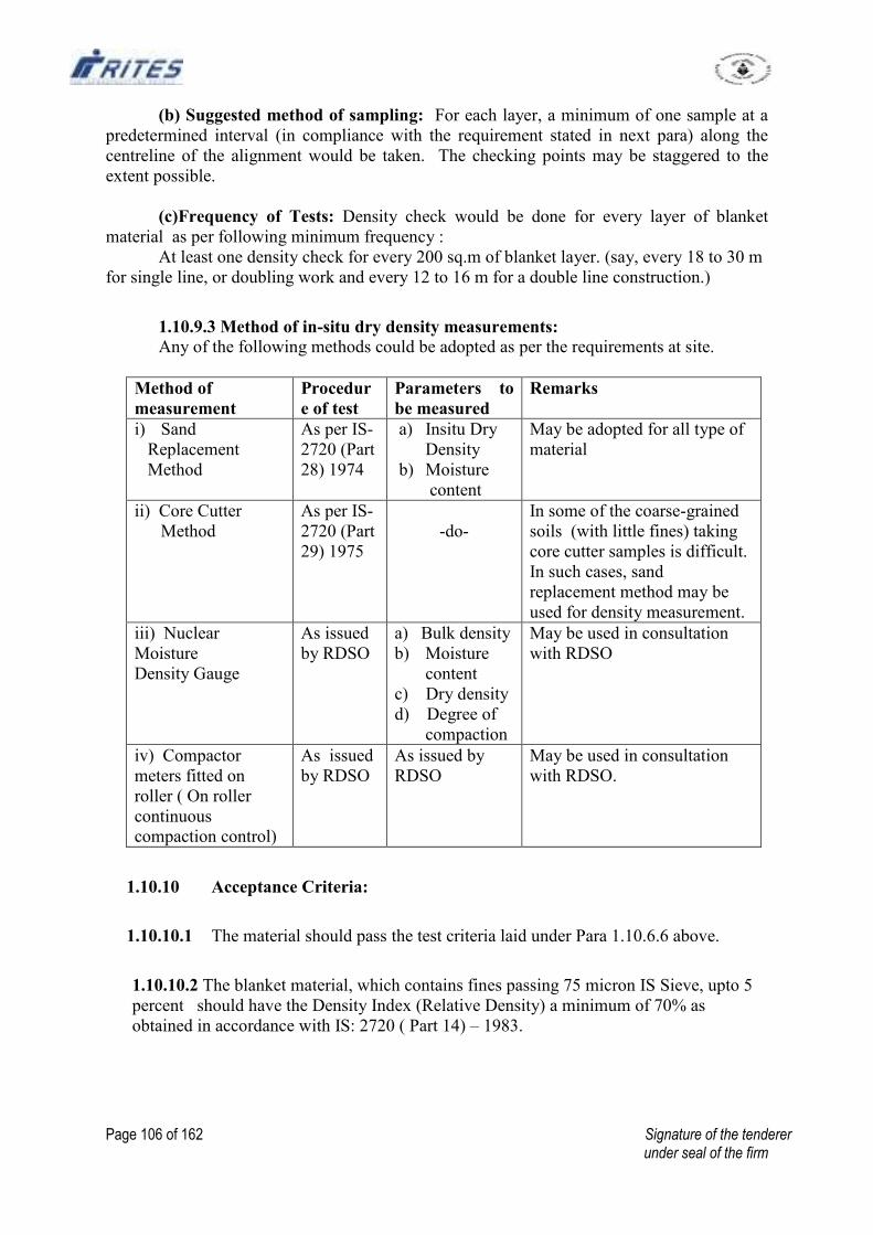
Page 106 of 162 Signature of the tenderer under seal of the firm
(b) Suggested method of sampling: For each layer, a minimum of one sample at a
predetermined interval (in compliance with the requirement stated in next para) along the
centreline of the alignment would be taken. The checking points may be staggered to the
extent possible.
(c)Frequency of Tests: Density check would be done for every layer of blanket
material as per following minimum frequency :
At least one density check for every 200 sq.m of blanket layer. (say, every 18 to 30 m
for single line, or doubling work and every 12 to 16 m for a double line construction.)
1.10.9.3 Method of in-situ dry density measurements: Any of the following methods could be adopted as per the requirements at site.
Method of
measurement
Procedur
e of test
Parameters to
be measured
Remarks
i) Sand
Replacement
Method
As per IS-
2720 (Part
28) 1974
a) Insitu Dry
Density
b) Moisture
content
May be adopted for all type of
material
ii) Core Cutter
Method
As per IS-
2720 (Part
29) 1975
-do-
In some of the coarse-grained
soils (with little fines) taking
core cutter samples is difficult.
In such cases, sand
replacement method may be
used for density measurement.
iii) Nuclear
Moisture
Density Gauge
As issued
by RDSO
a) Bulk density
b) Moisture
content
c) Dry density
d) Degree of
compaction
May be used in consultation
with RDSO
iv) Compactor
meters fitted on
roller ( On roller
continuous
compaction control)
As issued
by RDSO
As issued by
RDSO
May be used in consultation
with RDSO.
1.10.10 Acceptance Criteria:
1.10.10.1 The material should pass the test criteria laid under Para 1.10.6.6 above.
1.10.10.2 The blanket material, which contains fines passing 75 micron IS Sieve, upto 5
percent should have the Density Index (Relative Density) a minimum of 70% as
obtained in accordance with IS: 2720 ( Part 14) – 1983.
Page 107 of 162 Signature of the tenderer under seal of the firm
1.10.10.3 For other materials, field dry density should not be less than maximum attainable
dry density obtained in field compaction trial. However, in field compaction trial, the
maximum attainable dry density should not be less than 98% of MDD values as obtained by
Heavy Compaction Test (IS: 2720 (part 8) – 1983) in the laboratory. In case, there are
difficulties in achieving 98% of the MDD values as obtained by Laboratory test, in the field
trials, the same may be relaxed upto 95% of MDD with the specific approval of Chief
Engineer/construction, recording reasons of such relaxation.
1.10.10.4 During widening of bank in case of gauge conversion and rehabilitation of unstable
formation, compaction of blanket layer should be minimum 95% of MDD as obtained by
Laboratory test as per Heavy Compaction Test (IS: 2720 (part 8) – 1983) or 70% Relative
Density for cohesionless soil (IS: 2720 ( Part 14) – 1983).
1.10.11 Measurement:
1.10.11.1 Measurement of blanket material should be done on the basis of finished cross
section after the material and workmanship have been accepted as per the above criteria. No
deduction is to be made towards voids.
1.10.11.2 In very rare cases, where it is not possible to take blanket material on finished
subgrade, measurement may be done on the basis of stack measurement with the permission
of Chief Engineer in-charge. It may be necessary to frame different schedule items for
different methods of measurement. There should be no occasion to change the method of
measurement unless specifically provided for in the tender documents duly approved by
competent authority.
1.10.11.3 Method of measurement in case of stack measurement may be the same as in case
of ballast incorporated in "Specification for track ballast-1999".
1.10.11.4 It is advisable to tally the quantity and quality measured at site with the ' Incoming
Materials Register' maintained at plant (para 1.10.6.4) as a means of double check.
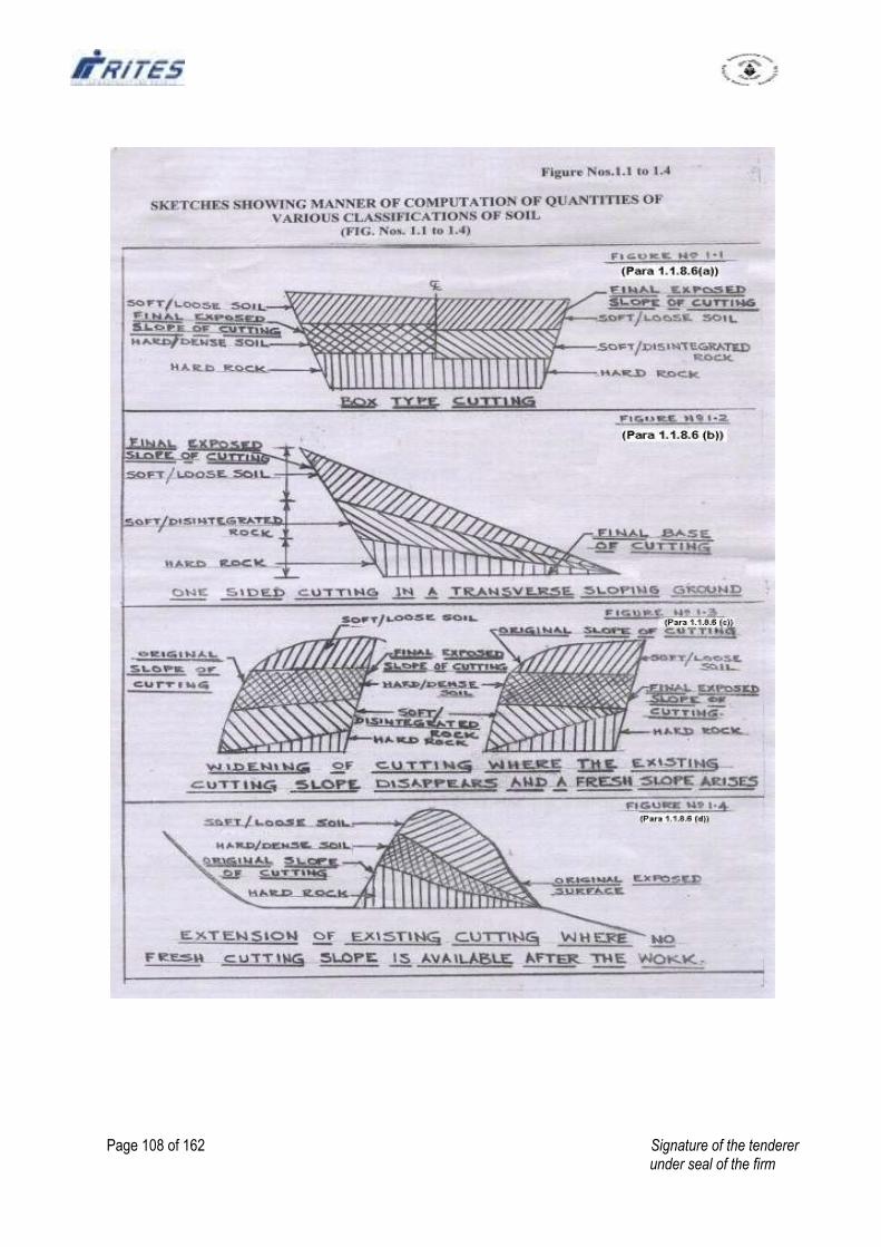
Page 108 of 162 Signature of the tenderer under seal of the firm
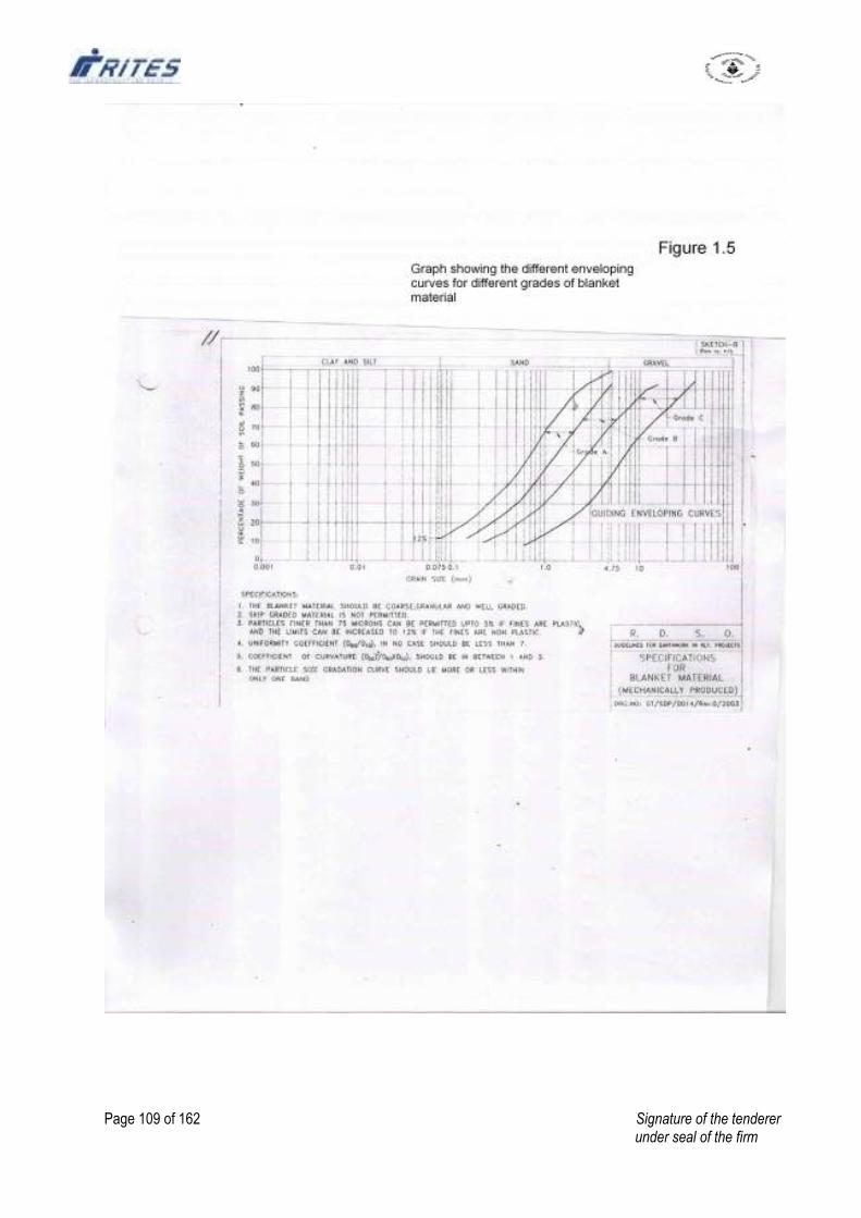
Page 109 of 162 Signature of the tenderer under seal of the firm
Page 110 of 162 Signature of the tenderer under seal of the firm
2. TECHNICAL SPECIFICATIONS FOR P.WAY WORKS
1. All works - linking of Railway tracks, assembly, laying and linking at points and
crossings, ballasting, through packing and connected works shall confirm to the
various instructions and specifications stipulated in "Indian Railways Permanent
Way Manual with upto date correction slips, IRS drawings, track manual and other
relevant Railway Codes/Manuals.
2. The proposed sidings will be mostly upgraded with 60 Kg/52 Kg/90R rails on
PSC/Metal/ Wooden sleepers in single rails as the case may be.
3. The Turn-outs/Diamond double slip (1 in 8½) assembly i.e. switch assembly, lead
portion and crossing assembly will be laid by 52 Kg/90 R/ 60 Kg rails as the case may
be to the Indian Railway Standard on PSC sleepers/STO/Wooden with a ballast
cushion as directed by Engineer in-charge or his authorized representative at site.
4. The operation of dumping ballast, lifting and packing should continue till such time
the track attains final level and shape of ballast section.
5. Pack the sleeper with ballast as directed by Engineer in-charge or his authorized
representative at site.
6. Lift the track to the required level as directed by Engineer in-charge or his authorized
representative at site.
7. Rails shall be connected by means of pair of fish plate in the first in stance only with
two bolts and nuts, one in each rail. The fishing planes of the fish plates and rail are to
be greased. Proper size of expansion liners are to be provided at the joints to ensure
correct expansion gaps. Cutting of rails where necessary, will be done to suit squaring
of joints.
8. On curves sharper than 5º (radius less than 360m) the rail joints will be mid-staggered
and check rails to be provided. All the sleepers of the sharper curves (radius less than
360m) to be provided with PSC sleepers having provision with check rail.
9. All the drilled bolt holes are to be chamfered by chamfering tools.
10. Paint mark shall be made on the rails showing the spacing of sleepers as directed by
Engineer-in-Charge at site.
Page 111 of 162 Signature of the tenderer under seal of the firm
11. Sleeper spacing:
a. Sleeper spacing for fish-plated joints having 13m/12m single rails:
Sleeper spacing M+7 density M+4 density
13m 12m 13m 12m
i) Rail ends to centre of sleeper 15cm 15cm 15cm 15cm
ii) Centre of joint sleeper to centre of 1st shoulder
sleeper
61cm 60cm 61cm 60cm
iii) Centre of 1st shoulder sleeper to centre of 2
nd
shoulder sleeper
64cm 63cm 70cm 69cm
iv) Centre of 2nd
shoulder sleeper to centre of
intermediate shoulder sleeper
68cm 66cm 84cm 83cm
b. Sleeper spacing for SWP of 3X13m/3X12m/3X 11m rails:
Sleeper spacing M+7 density M+4 density
39m 36m 39m 36m 33m
i) Rail ends to centre of sleeper 15cm 15cm 15cm 15cm 15cm
ii) Centre of joint sleeper to centre of 1st
shoulder sleeper
59cm 58cm 66cm 62cm 60cm
iii) Centre of 1st shoulder sleeper to centre of 2
nd
shoulder sleeper
61cm 60cm 75cm 67.5cm 66cm
iv) Centre of 2nd
shoulder sleeper to centre of
intermediate shoulder sleeper
66cm 64cm 78cm 77cm 77.5cm
c. Sleeper spacing for curve with Mid-staggered Joint:
Sleepers =18 nos. per single rail length.
Sleeper spacing 18 sleeper per rail
13m 12m
i) Rail ends to centre of sleeper 15cm 15cm
ii) Centre of joint sleeper to centre of 1st shoulder sleeper 65cm 65cm
iii) Centre of 1st shoulder sleeper to centre of 2
nd shoulder sleeper 75cm 70cm
iv) Centre of 2nd
shoulder sleeper to centre of intermediate shoulder sleeper 85cm 75cm
12. Full quantities of small fittings are to be fitted completely after slewing the track to
correct alignment as directed by Engineer-in-Charge at Site.
13. The track so linked shall be aligned correctly to the alignment pegs given or as
directed by Engineer till it takes correct position and the remaining two bolts to be
fixed in fish plated joints.
Page 112 of 162 Signature of the tenderer under seal of the firm
14. During the above process, alignment, adjustment and squaring of sleepers, gauging,
Cross level and longitudinal levels should be checked and rectified by doing packing
as directed.
15. The operation of spreading of stone ballast, lifting and packing should continue till
such time the track attains final level and shape.
16. Greasing of fish plates, fish bolts and nuts with lubricating oil and graphite grease to
be done by cleaning fishing planes of rail ends with wire brush.
17. Screening of Track should be done as per Indian Railways Permanent Way Manual
Para-238 and as per direction of Engineer- in- Charge. For screening work,
required wooden blocks & wedges are to be arranged by the contractors. No
extra payment will be made for arranging wooden blocks.
18. The works should be executed in a workman like manner to the satisfaction of
the Engineer-in-Charge at site. The contractor will be primarily responsible for Safety
of traffic that moves on opened up track, not withstanding the presence of RITES
representative at site.
19. Good quality track ballast as per specification and of approved quality will have to
be supplied and stacked on ‘Cess’ of formation or at the toe of bank or at suitable
places as directed by RITES representative. Stacks will be measured jointly by the
contractor and RITES' s representative and entered in a register to be signed jointly
by them.
20. Lifting and spreading of stone ballast includes all lead, lift, ascent, descent,
crossing road/ railway, handling as required for packing tracks from the stacks
measured and passed already including all labour, tools and plants for the
operation and the same will be arranged by the contractor at his own cost. The
payment for spreading will be made based on measurement of ballast supplied in
stacks, less shrinkage.
21. Pulling out of ballast on to the formation by ballast rakes and boxing is to be done as
per specified profiles. Proper templates and loglines should be used. The width
at the shoulder should be as directed by Engineer-in-Charge which will
normally be not less than 3.55 metre (11'-0") and not more than 3.66 metre
(12'-0").
22. No ballast should be wasted on the slopes of banks or in cuttings or any places.
23. After the ballast is measured, the Contractor shall spread it on top
of the blanketing surface/formation/in the track with standard profile. After
spreading, the ballast profile should be consolidated.
Page 113 of 162 Signature of the tenderer under seal of the firm
24. The thickness of the finished ballast spread should be as specified by the
Field Engineer, and the layer should be dressed and boxed to proper profile and
dimensions.
25. While spreading the ballast on the finished formation, care shall be taken
that the formation/blanketing surfaces is not damaged. In no circumstances,
vehicular carts/trucks shall be permitted to ply on the finished blanketing/ formation.
In case some damage to the surface is done, the Contractor shall repair the damages at
his own cost before spreading the ballast.
26. Through packing of railway track on any type and any density of sleepers which
will consist of –
(i) Opening of the road,
(ii) Examination of rails, sleepers and fastenings,
(iii) Squaring of sleepers,
(iv) Slewing of track to correct alignment,
(v) Gauging,
(vi) Packing of sleepers including lifting & leveling,
(vii) Repacking of joint sleepers,
(viii) Boxing of ballast section & tidying.
27. The length of track to be opened out on any day must not be more than that can be
efficiently tackled by the end of the day. Broken or missing fittings are to be replaced
and loose ones tightened. Cross drains are to be provided at mid section each rail
except sharper curve track. On sharper curve track the cross drains are to be provided
as per direction of Engineer in-charge.
28. Through packing of points and crossings 1 in 8.1/2 or diamond x-over / derailing
switch will comprise opening out of ballast, squaring of sleepers, replacing or
readjusting fittings to keep correct gauge clearances of check rail, wing rails, etc.
including lifting or lowering as necessary and packing all the sleepers in the points
and crossings efficiently and finishing all works with boxing and dressing of the
shoulder ash ballast neatly. All bolts and nuts including crossing bolts, check rail
bolts, slide chairs, tongue rails, heel block bolts etc. are to be properly oiled and
greased also.
29. Picking up slacks will include lifting and packing of sleepers where necessary,
attention to all fittings and fastenings, adjusting gauge, cross level and longitudinal
level, cleaning of drain etc. as directed by the RITES' representative at site at
specified scattered locations. The work should be neatly finished with proper boxing.
30. Any sleeper which have shifted from correct spacing or gone out of square shall be
moved back and square after loosening the fastenings. The fastenings shall be
tightened again after squaring.
Page 114 of 162 Signature of the tenderer under seal of the firm
31. The track shall be slewed to correct alignment by sighting along the rail head of the
base rail. It should be ensured that track does not get lifted in the process of slewing.
32. The track shall then be given a final packing. For this, sighting shall be done along
the base rail and any dip or low joint are found, the same are to be attended for its
correction by packing of sleepers. After the base rail is thus packed for two or three
rails length, the cross level should be checked and the opposite rail lifted wherever
necessary and sleepers under the rail seat packed.
33. The joint and shoulder sleepers shall be re-packed and cross level adjusted at the
time of each through packing of sleepers.
34. Oiling and greasing hand operated points will include adjusting the point Roding
and fixing hand lever frame, where found necessary by means of spikes with the
sleepers for smooth operation of the point and adjusting the opening between tongue
rail and stock rail. For any bent tongue rail, if required, Jim-crowing may have to be
done and the gap adjusted as required. Blacksmith and other staff for this work, as
required, will be deputed by the Contractor at his cost. Oil & Grease to be supplied by
the Contractor at his own cost.
35. Gauge:
Will be with standard broad gauge on straight and curves upto 350 m radius and 5
mm slack on sharper curves with a Permissible variation with (+) or (-) 3mm. But
not exceeding 1 mm between consecutive sleepers.
36. Alignment:
Should be perfectly straight verified by sighting. On curves, the alignment should be
correct of versine or as directed by the Engineer-in-Charge, who will pass the work.
i) Straight on 10M chord = (+) or (-) 2mm;
ii) Curves of radius 600M on 10M chord = (+) or (-) 5mm;
iii) Curves of radius 600M on 20M chord = (+) or (-) 10mm.
37. Level:
To be checked by level board and spirit level. Track should be free from sag and low
joints. Permissible variation of Cross levels being (+) or (-) 3 mm. but not
exceeding 1 mm between consecutive sleepers.
38. Joint out of square :
i) On straight = (+) or (-) 10mm;
ii) On curves = 1/2 pitch of fish bolt holes.
39. High Joint: Permissible upto 2mm.
40. Low Joint: Not permissible.
Page 115 of 162 Signature of the tenderer under seal of the firm
41. All the elastic rail clips should be thoroughly cleaned. Grease to IS:400-1981
(Specifications for Grease No. 'O' Graphite) should then be applied on Central leg of
the E.R.C. and eye of Inserts and then the clip should be driven at the
time of assembly. The rate accepted includes the cost of the grease as per
specifications and labour.
42. During execution of the work, contractor should arrange for protection of track and
displaying the signals as per extent rule of Indian Railways.
43. All the P. Way tools such as (a) Rail tongs, (b) Crow bars, (c) Fishing spanners, (d)
Hammers, (e) Keying hammers, (f) Cotter splitters, (g) Shovels, (h) Mortar Pans,
(i) Beaters, (j) Track Lifting Jacks, (k) Gauges, (l) Level Board, (m) Spirit levels,
(n) Cant Board, (o) Expansion Liners, (p) Wooden Squares, (q) Steel Tape ®
Wire brushes, (s) Cotton waster, (t) Rake Ballast, (u) Chamfering tools, (v) Soap as
required for the work as assessed by the Engineer- in-Charge depending on the
labour strength will be arranged by the contractor at his own cost
Page 116 of 162 Signature of the tenderer under seal of the firm
2.SPECIFICATIONS FOR SUPPLY OF BALLAST
(BASED ON IRS-GE-1/JUNE-2004)
1.0 Ballast Supply :
1.15 This specification will be applicable for stone ballast to be used for all types of
sleepers on normal track, turn-outs, tunnels and deck slabs etc on all routs.
2.0 Quality of stone ballast in General :
2.1 Basic quality: Ballast should be hard durable and as far as possible angular along
edges/corners, free from weathered portions of parent rock, organic impurities and
inorganic residues.
2.2 Particle shape: Ballast should be cubical in shape as far as possible. Individual pieces
should not be flaky and should have generally flat faces with not more than two
rounded/ sub- rounded faces.
2.3 Mode of manufacture: The ballast shall be machine crushed and conforming to the
Railway specifications for machine crushed ballast.
2.4 Physical Properties: The ballast samples when tested for physical properties
(abrasion and impact) in accordance with IS: 2386 (Part-IV)-1963 should have the
under mentioned values:
i) Aggregate Abrasion Test (Using 105 Angles Abrasion Testing Machine).
Aggregate Abrasion value (Percent) - Maximum 30%.
ii) Aggregate Impact Test.
Impact values (Percent) – Maximum 20%
2.5 The water absorption test as per IS: 2386, Part-III-1963, which should not be
more than 2.5% vide correction slip-3 issued by Railway Board.
2.6 Track ballast should be obtained from good quality stones / boulder; and top layer, if
weathered, must not be used.
3.0 Size and Gradation of ballast:
3.1 The track ballast shall be well graded of the following size: -
a) Retained on 65 mm square mesh sieve - 5% maximum.
b) Retained on 40 mm square mesh sieve* - 40% to 60%
c) Retained on 20 mm square mesh sieve - not less than 98% for machine crushed.
- not less than 95% for hand broken.
* For machine crushed ballast only.
Page 117 of 162 Signature of the tenderer under seal of the firm
4.0 Over-size and under-size ballast :
4.1 Over-size ballast Tolerances:
4.1.1 Retention on 65 mm square mesh sieve: A maximum of 5% ballast retained on 65
mm square mesh sieve shall be allowed without deduction of in payment.
In case ballast retained on 65 mm square mesh sieve exceeds 5% but does not exceed
10%, payment at 5% reduction in contracted rate shall be made for the full stack.
Stacks having more than 10% retention of ballast on 65 mm square mesh sieve, the
stack shall be rejected.
In case ballast retained on 40 mm square mesh sieve (machine crushed case only)
exceeds 60% limit prescribed in 3.1 (b) above, payment at following reduced rates
shall be made for the full stack in addition to the reduction worked out at 4.1.1 above.
5% reduction in contracted rate shall be made if retention on 40 mm Square mesh
sieve is between 60% (excluding) and 65% (including).
10% reduction in contracted rate shall be made if retention on 40 mm Square mesh
sieve is between 65% (excluding) and 70% (including).
4.1.3 In case retention on 40 mm square mesh sieve exceeds 70%, the stack shall be
rejected.
4.1.4 In case of Hand broken ballast supply, 40 mm sieve analysis may ot be carried out.
The executive may however ensure that the ballast is well graded between 65 mm and
20 mm.
4.2 Under-size ballast – Tolerances :
The ballast shall be treated as under-sized and shall be rejected if-
4.2.1 Retention on 40 mm Sq. mesh sieves less than 40%.
4.2.2 Retention on 20 mm Sq. mesh sieve is less than 98% (for machine crushed ballast) or
95% (for Hand broken ballast).
5.0 Sieve analysis for size and gradation:
The screens for sieving ballast shall be of square mesh and shall not be less than
100cm in length, 70cm in breadth and 10cm in height on the sides. The squareness of
the individual hole in the sieves viz. 65, 40 and 20 mm should be ensured. The sieves
to be used for the sieve analysis.
Page 118 of 162 Signature of the tenderer under seal of the firm
Sieve sizes mentioned above are the nominal sizes. However the following tolerances
in the sizes of holes for 65, 40 and 20 mm nominal sizes are permitted.
65mm square mesh sieve plus minus (±) 1.5mm
40mm square mesh sieve plus minus (±) 1.5mm
20mm square mesh sieve plus minus (±) 1.0mm
When carrying out sieve analysis, the screen shall not be kept inclined, but held
horizontally, and shaken vigorously. The pieces of ballast retained on the screen can
be turned with hand to see if they pass through but should not be pushed through the
screen openings.
The percentage of ballast passing through or retained on the sieve shall be
determined by weight.
6.0 Sampling of ballast:
6.1 A minimum of 3 samples of ballast for sieve analysis shall be taken for measurement
done on any particular date even if the numbers of stacks to be measured are less than
three.
6.2 The test viz. determination of Abrasion value, Impact value and water absorption
value should be got done through the following laboratories/Govt. Institutions.
Any Zonal Railway Laboratory or any Railway approved Laboratory/ Institution.
National Test House, Alipore, Kolkata
RITES Laboratory (where available),
Any Govt. laboratory/institution
6.3 In order to ensure supply of uniform quality of ballast, the following norms shall be
followed in respect of sampling, testing and acceptance.
6.3.1 On supply of first 100 cum. the test for size, Gradation, Abrasion value, Impact value
and water absorption value (as prescribed) shall be carried out. Further supply shall
be accepted only after this ballast satisfies the specification for these tests. RITES Ltd
reserves the right to terminate the contract at this stage itself in case the ballast supply
fails to conform with any of these specifications.
6.3.2 All Costs towards the laboratory test should be borne by the contractor.
Page 119 of 162 Signature of the tenderer under seal of the firm
6.3.3 Subsequent tests shall be carried out as follows:
Sl.
No
.
Supply in stacks
For each stack of volume
less than 100 cum
For each stack of volume
more than 100 cum.
(a)
Size & Gradation Test :-
Testing frequency --------
Size of sample ------------
One for each stack.
** 0.027 cum
One for each stack.
** 0.027 cum. for every
100 cum or part
thereof.
(b) Abrasion value, Impact
value and Water absorption
Tests ** :-
Testing frequency --------
One for every 2000 cum.
** This sample should be collected using a wooden box of internal dimension 0.3m x
0.3m x 0.3m from different parts of the stack/wagon.
These tests shall be done for the purpose of maintaining quality during supply. In
case of the test results not being as per the prescribed specifications at any stage,
further supplies shall be suspended till suitable corrective action is taken and supplies
ensured as per the specifications.
The above tests may be carried out more frequently if warranted at the discretion of
Engineer-in-charge of RITES Ltd.
All tests for Abrasion value, Impact value and water absorption value conducted
subsequently after award of contract shall be done as per direction of In-charge of the
work at contractor cost.
6.4 In the event of the ballast being rejected the Contractor/Agency will have to remove
the rejected ballast from the work-site expeditiously at his own cost.
6.5 The Engineer shall mark all rejected ballast in any manner he considers fit to prevent
them from being removed and mixed with good/accepted ballast and the Contractor
shall within a fortnight from the date of the order of removal, remove the rejected
ballast to such place as may be directed by the Engineer and, in the event of
contractor’s failure to do so the Engineer may cause it to be removed and all costs of
such removal shall be payable on demand by the Contractor to RITES Ltd and
without prejudice to any other mode of recovery, may be deducted from any money,
that may be due or may become due to the contractor or from the Contractor’s bill for
any other works executed for RITES Ltd on behalf of Employer.
6.6 Should RITES Ltd, under any special circumstances, agree to take over all or part of
the rejected ballast, the same will be paid for at rates to be fixed by the authority
accepting the tender and agreed to by the contractor in writing.
Page 120 of 162 Signature of the tenderer under seal of the firm
7.0 The screen for sieve analysis as specified in specification as also the standard box for
measuring volume should be kept available at site by the contractor at his own cost,
for use by the Engineer or his representative after proper check, in carrying out sieve
analysis. Labours required for doing sieve analysis will be supplied by the contractor
free of cost. The contractor must also accept the results of such analysis in writing.
8.0 Each stack of ballast shall be serially numbered and may be as long and broad as
possible. After the stacks are measured, they should be sprinkled with lime in the
form of cross on all the sides of the stack at the contractors own cost to the
satisfaction of the Engineer-in-Charge of RITES Ltd. Suitable space should be left in
between stacks in adjacent zones so that there is no possibility of materials of fresh
stacks in one zone mixing with stacks already measured in the adjacent zone.
9.0 Entries in the ballast measurement register should not be over written. If any
correction is required the same should be done by striking off the old entry by
drawing a line and showing proper entry by its side.
10.0 Ballast is to be stacked proper trapezoidal section on the cess or berms, or on the line
or in depots as may be ordered by the Engineer concerned, in stacks as large as
possible and ordinarily not less than 1.0 metre in height except hilly areas where it
may 0.5 m. The height shall not be mote than 2.0 m. Top width of the stack shall not
bee less than 1.0 metre. Top of stack shall be kept parallel to the ground plane. The
side slopes of stack should not be flatter than 1.5: 1 (Horizontal: Vertical). Cubical
content of each stack shall normally be not less than 30 (thirty) Cum in plain areas
and 15 cum in hilly areas.
11.0 The Engineer should, as far as possible, set out the sites for ballast stacks. Stacking
ground must be fairly dressed to a proper plane by the contractor at his own cost
before stacking is started. Completed stacks must be properly finished before being
offered for acceptance and measurement.
12.0 It must be distinctly understood that the accepted rate is for ballast which conforms in
all particulars of quality, stack measurements, gauge, completion within time limit
and delivery at site fixed upon, with the specification and conditions of contract. If,
therefore, the officer deputed to measure up a Contractor’s ballast is not satisfied that
the above conditions and specifications have been complied with, he is at liberty to
take either of the following courses.
To refuse to measure up such ballast at all giving his reasons in writing for so doing to
the Contractor.
To call upon the contractor in writing to screen his ballast of dirt and admixtures
beyond the specified limit or to break it to gauge, or to re-stack it to proper
dimensions, or all three as may be required, prior to further inspection and
measurement by a fixed date, within the time limit imposed in the agreement.
13.0 The contractor shall provide at his own cost adequate labour and tools for opening out
stacks for inspection and for carrying out screening test.
Page 121 of 162 Signature of the tenderer under seal of the firm
14.0 The contractor shall supply all necessary tools for the work and also bamboos, pegs,
strings etc. necessary for measurement of ballast.
15.0 Wagon Measurement:
In case ballast supply taken by direct loading into wagons, a continuous white line
should be painted inside the wagon to indicate the level to which the ballast should be
loaded. The cubical content in cubic metre corresponding to white line should also be
painted on both sides outside the wagon.
In addition to painted line, mentioned in para 15(i) above, short pieces of flats (cut
pieces of tie bars or otherwise) with cubical contents punched shall be welded at the
centre of all the four sides as permanent reference. In case the supply is taken in
general service wagon, actual measurements will be taken.
16.0 Shrinkage allowance:
Payment shall be made for the gross measurement either in stacks or in wagons
without any deduction for shrinkage/voids. However, when ballast supply is made in
wagons, shrinkage upto 8% shall be permitted at destination while verifying the
booked quantities by the consignee.
17.0 Stack measurement:
The quantity shall be calculated as per the following formula for the ballast supplied.
Q
=
LB + LT
--------
2
X
WB + WT
---------
2
X
H
When, Q = Quantity of Ballast
LB = Average length of the stack at the bottom.
LT = Average length of the stack at the top
WB = Average width of the stack at the bottom
WT = Average width of the stack at the top
H = Average height of the stack.
The plan of the stack should be either square or rectangular.
--oo00oo—
Page 122 of 162 Signature of the tenderer under seal of the firm
ANNEXURE - 'A'
3.TECHNICAL SPECIFICATION FOR THERMIT WELDING
1.0 Portion for welding.
1.1 The 'portion' used for welding shall conform to the technical requirements as
mentioned in IRS:T-19-1994. The suitability of the 'portion' for the welding process
in respect of the type and section of rails to be welded shall be ensured before
commencing welding. Only RDSO certified/passed portions should be used for
welding.
1.2 Equipment and staff for welding : The list for one set of A.T. welding equipment
by short preheating process is given in Annexure 2. The composition of thermit
welding team is given in Annexure 3.
1.3 Preparation of rail ends to be welded : The rail end face and adjacent sides at foot
(top and bottom), web and head up to 50 mm shall be thoroughly cleaned using
kerosene oil and brushing with wire brush to remove all dirt, grease and rust
before welding. Any burrs at the rail ends shall be removed by chiseling or
grinding.
Normally, no alumino -thermic welded joint shall be located closer than 4 m from
any other welded or fish plated joint.
1.4 Gap between rail ends : The two rail ends to be welded shall be held in position
with a uniform and vertical gap as per gap specified in Annexure 1. The uniformity
and verticality of the gap shall be measured by a gauge prior to welding. In case of
wide gap 50 + 1 / 75 + 1 mm welding, for repairing fractured /defective welds, it
shall be ensured that the end faces are vertical. In LWR/CWR territory,
hydraulic/mechanical rail tensor of suitable and approved design should be used
for maintaining correct rail gap during welding.
1.5 Preliminary work prior to welding.
1.5.1 In case of in-situ welding the rail fastenings for at least five sleepers on either side
of the proposed weld shall be loosened. The sleepers adjacent to the joint to be
welded shall be shifted to obtain a clear working space of 250 mm on either side to
accommodate the moulds, clamps, preheating equipment, etc. The rails shall then
be properly aligned, both horizontally and vertically.
1.5.2 When the welding work is carried out on cess, full rail length shall be levelled by
supporting on at least ten wooden blocks on either side. The rails shall be
properly aligned in horizontal and vertical direction and held in position.
1.6 Alignment of rail ends before welding
1.6.1 The rail ends to be welded shall be aligned in horizontal and vertical planes to the
dimensional limits indicated below.
1.6.1.1 Lateral alignment : The two rail ends, after alignment shall be within + 0.5
mm. when checked with a 1.0 m straight edge at rail ends [ Fig. 4.7.1.1(a) & (b)].
Page 123 of 162 Signature of the tenderer under seal of the firm
Any difference in the widths of rail heads shall always be fully kept on the non-
gauge side, correctly aligning the rail ends on the gauge face.
1.6.1.2 Vertical alignment:The joint shall be kept higher by 3 to 4 mm for 72 UTS
rails and 2 to 2.4 mm for higher UTS rails when measured at the end of 1 m straight
edge ( as compensation against sagging caused by differential shrinkage on cooling)
(Fig. 4.7.1.2). This shall be achieved by wedges applied on the rail supporting blocks
on both sides of the joint.
1.7 Fixing of mould
1.7.1 Only prefabricated moulds supplied by the portion manufacturer shall be used for
welding. These are to be made by mixing high silica sand to IS:1987 with sodium
silicate to the required consistency, followed by passage of carbon dioxide gas.
These prefabricated moulds shall have adequate permeability for escape of mould
gases and adequate reinforcement to avoid mould crushing during transportation and
welding.
1.7.2 Before mounting on the rail ends to be welded, each pair of moulds shall be
examined for defects, dampness, cracks, blocked vents, etc. and defective moulds
discarded. The prefabricated moulds shall be handled with care as they are fragile
and liable to breakage.
1.7.3 During fixing the moulds, it shall be ensured that the Centre line of the rail gap
coincides with Centre line of the mould to avoid cross joint. The mould
jackets/shoes holding the pre-fabricated mould in a snug fit condition, after fixing,
shall be tightened by the application of adequate pressure. Excessive pressure may
cause breakage of mould and dropping of sand inside the mould cavity. Care shall
be taken during application of adequate pressure, it is essential for the moulds to fit
flush to each other across the bottom of the rail flange which can be checked by
feeling with fingers across the junction of the two halves of the moulds and by
looking down the riser aperture. The moulds should touch the bottom of rail foot
to ensure proper size of collar at the bottom.
1.7.4 After fixing the moulds, the gap between mould and the rail shall be packed firmly
with luting sand to prevent leakage of liquid weld metal. To protect the rail top table
from metal splashes during reaction, the adjacent rail surface on either side of the
moulds shall be covered with metal cover or smeared with luting sand upto 15 cm. on
either side.
1.8 Preheating
1.8.1 After fixing and luting of the moulds, the rail ends shall be uniformly pre-heated
throughout the rail section with specially designed air petrol/compressed air petrol/
oxygen-LPG burner as the case may be. The flame shall be properly adjusted to
achieve the desired rail temperature. The pre-heating shall be done from the top of
the mould box for stipulated period for welding technique adopted, so as to achieve a
temperature of around 600 + 200C.
1.8.2 In welding process using air petrol burner, the compressor tank pressure during
operation of the burner shall be maintained at 7 + 0.70 kg/cm2
(100 + 10 lb per sq.
in). In case of pre-heating by oxygen and LPG cylinders shall be adjusted in the
range of 7.0-8.0 kg/cm2 and 2.0-2.5 kg/cm
2 respectively. While preheating with

Page 124 of 162 Signature of the tenderer under seal of the firm
oxy-LPG burner LPG supply should be opened first and the gas ignited, thereafter
oxygen supply should be opened. While closing, oxygen supply should be stopped
first followed by LPG supply. The burner shall be properly adjusted during
preheating to ensure that the head, web and foot of both the rail ends are heated
uniformly.
1.8.3 Preheating time : Preheating time would be about 10 to 12 minutes and 2 to 2.5
minutes for air-petrol and oxy-LPG preheating techniques respectively. The actual
preheating time would depend upon the rail section and welding technique adopted
as given in Annexure 1.
1.8.4 Special emphasis shall be given to the tank pressure, efficiency of burner and
flame condition for achieving required rail temperature within the stipulated time.
From time to time or in case of any doubt with a view to maintain proper quality
control, temperature measuring devices like optical pyrometer, contact type
pyrometer or temperature indicating crayons may be used for measuring rail end
temperature just after completion of preheating i.e. after removal of burner.
1.9 Welding
1.9.1 The crucible lined with refractory material (magnesite/crushed alumina slag) and
fitted with bottom stone and thimble shall be preheated before making the first weld
of the day to ensure freedom from moisture.
1.9.2 Slag shall be cleaned from the crucible after each reaction, if necessary. During
cleaning, care shall be taken not to damage the refractory crucible lining. The lining
shall be examined regularly and patch repairing, or relining as necessary shall be
carried out.
1.9.3 The crucible shall be positioned relative to the pouring gate with respect to its height
from the mould after it has been placed on the stand mounted on the rail head. The tap
hole in the crucible shall be sealed with closing pin, asbestos powder and stag power.
The 'portion', for the required technique, shall be thoroughly hand mixed and poured
into the crucible striking the crucible wal so that the bottom plugging remains
undisturbed. The portion shall be coned to the Centre of the crucible and a sparkler be
placed at the top. The crucible shall then be brought to the proper position over the
mould in line with the pouring gate of the mould with a vertical distance of about 50
mm. between the tap hole and sand core/top of the pouring gate.
1.9.4 After preheating the rail joint, the sparkler shall be ignited and inserted in the portion
at the Centre top to start the reaction. The reaction shall not be vigorous or boiling. By
the time the reaction is completed the burner shall be removed quickly and the gap
closed with a dried sand core in case of central pouring to prevent loss of heat and
turbulence during flow of metal. The time period between removal of burner and
tapping of metal should be as minimum as possible. After the reaction subsides,
about three seconds shall be allowed for the separation of slag from the metal,
which may be judged by looking into the crucible through coloured glass to
IS:5983. Thereafter, the molten steel shall be tapped into the mould by striking the
closing pin with a tapping rod. It shall be ensured that since the commencement of
the reaction, thermit steel is tapped within the time limit as specified in Annexure 1.
Care shall be taken to ensure that the crucible does not move from its position
during tapping. When pouring is over, the crucible and swivel stand shall be
removed and kept aside without disturbing the joint. If the reaction is found to be
Page 125 of 162 Signature of the tenderer under seal of the firm
boiling, the metal shall be out-tapped. Vivorous reaction and loose closing of
crucible may cause self tapping. In this case also, the metal shall be out tapped. If,
in any case, self tapped metal enters the mould, the joint shall be rejected, cut and
rewelded. In cases of out tapping, the joint should be cooled to ambient
temperature and the process of welding restarted a fresh. However, if temperature
can be measured, the rail end may be heated to an extent so as to achieve
temperature of about 600 + 20
0 and welding of joint may be completed.
1.9.5 After pouring, molten metal shall be allowed to cool and solidify with mould
intact for the stipulated time (mould waiting time) depending upon the rail section
and ambient temperature. In case of alloy steel rails, full rail section up to 300 mm
on either side of the joint shall be heated by using burner during this period. The
mould shoes shall be removed just prior to completion of mould waiting time.
The mould waiting time is generally four to six minutes for 25 mm gap joints. After
the mould waiting time has elapsed, the trimming should be done by using weld
trimmer of suitable and approved design without knocking out the mould. List
of approved manufacturers of rail profile weld grinder and weld trimmer is given at
Annexure 4.
In the ventuality of sudden failure of weld trimmer, manual chipping may be
resorted to. In case of welding of old rails, if it is not possible to use weld trimmer
due to flow of metal at rail head, manual chipping should be done.
1.9.6 During the trimming operation, it shall be ensured that the wedges used in aligning
are in their proper places without loosening, and they are not removed for at least
20 minutes after stripping. The runner and riser must not be removed until cold, and
that too only by knocking towards the rail.
1.9.7 No welding shall be carried out if it is raining. In case, the rains start while the joint
is under execution, immediate arrangement to adequately cover the site shall be
made.
2.0 Operations subsequent to welding.
2.1 Post weld cooling
In case of welding of head hardened rails, the average hardness of the HAZ of the
rail becomes considerably less than the parent rail hardness. This lower hardness
is due to transformation of rail steel occurring at cooling rate much lower than
that achieved during the original head hardening operation. Such a hardness
difference can lead to differential plastic deformation during wheel rail contact
which may cause localized cupping. head hardened rails, therefore, must be
subjected to controlled quenching for a specific time by the arrangement approved
for the technique.
2.2 Post weld packing of sleeper : Before the passage of traffic, the wedges used for
aligning should be removed and joint sleepers which were shifted to obtain the clear
gap of 250 mm on either side as per para 1.5.2 shall be re-shifted to the original
location and repacked. Packing of these re-shifted sleepers should be carried out
gently and carefully.
2.3 Passing of traffic : The first train should be allowed to pass on the newly welded
joint only after 30 minutes have elapsed since pouring of weld metal. Necessary
speed restriction shall be observed until the grinding operation is over.
Page 126 of 162 Signature of the tenderer under seal of the firm
2.4. Grinding.
2.4.1 After the excess metal is trimmed off, the grinding of the remaining metal on the
rail table and the sides of the rail head shall be carried out only with rail profile
guided grinding trolley of approved design. Use of hand files should not be resorted
to except in unavoidable circumstances. In the case of in-situ joints, the grinding shall
commence only after the sleeper fastenings are reflexed, after the removal of
wedges. The rail table shall first be ground down to original profile and checked by
a one metre straight edge. This should be followed by grinding of the sides of rail
head. The accuracy of grinding shall be checked by using 10 cm straight edge. While
grinding, only light pressure should be applied and grinding wheel should be moved
to and fro to avoid local over heating.
2.4.2 Tolerances on finished welds : All the finished joints shall be checked to ensure
that the joint geometry is within the following tolerances:
(i) Vertical alignment : Variation not more than + 1.0 mm,-0 mm measured at the
end of one metre straight edge.
(ii) Lateral alignment : Variation not more than + 0.4 mm. -0 mm measured at the
end of 10 cm straight edge.
(iii) Finishing of top surface : + 0.4 mm, -0 mm measured at the end of 10 cm
straight edge.
(iv) Head finishing on sides : + 0.3 mm over gauge side of the rail head measured
at the Centre of 10 cm straight edge.
Note : In specific cases, for joint geometry, in case of old rails, dispensations may be
permitted by Chief Engineer.
The method of checking the geometry of welded joints is illustrated in Fig. 5.4.2.
2.5 Record of joint geometry : The details of geometry of each joint shall be jointly
signed by the firm's and RITES' representative and kept as record. Any joint found not
conforming to the above stipulations shall be cut and rewelded, free of cost, by the
firm.
2.6 Marking.
Each joint shall have a distinctive mark indicating month, year, agency, welder's
code and weld number of the welded joint in the following manner.
Month Last two Agency Specific Weld No.
digits of person
Year number
This should be done by punching on an aluminium strip of suitable thickness and
dimension of 30 x 100 mm which should be fixed to the web of the rail with epoxy
adhesive at approximately 300 mm from the joint. The welded joints shall be serially
numbered. Repair welds/additional welds done at a later date may be given
continuing weld number. For example, the last thermit weld number 88 and
Page 127 of 162 Signature of the tenderer under seal of the firm
subsequently a thermit weld has been executed, it shall be numbered 89, irrespective
of its location. Engineer-in-Charge shall maintain 'Thermit Weld Register' as per
proforma given in Annexure 5. No punch marking should be done on the rail.
2.7 Painting of thermit welds
Painting of weld collar should be done on all welds to protect them against normal
and severe corrosion immediately after the welding. The procedure of painting and
specification of paint is outlined in Annexures 6 and 7.
3.0 Accepted tests
3.1 Visual Inspection : All the welded joints shall be examined carefully to detect any
visible defect like cracks, blow holes, etc. Any joint, which shows any visible
defect should be rejected.
3.2 Dimensional check : All finished joints shall be checked for dimensional
tolerances which should be within the tolerances as specified in para 2.4.2.
3.3 Ultrasonic flaw detection test : All the fusion welded joints shall be ultrasonically
tested and accepted by the purchaser or his representative as per the 'Procedure for
ultrasonic testing of thermit welded rail joints' given at Annexure 8. This testing
shall be completed as early as possible but in any case before the contractor/welding
team leaves the welding site.
3.4 Rewelding of defective joints.
3.4.1 All the joints found to be defective as per acceptance tests as given in paras 3.1,
3.2 & 3.3 and/or joints failed in guarantee period as specified in para 4.3 will be
cut and rewelded by the firm free of cost using their portions, equipment, labour
and consumables.
3.4.2 Where one bad joint is required to be replaced by two new joints, the entire cost
of both the joints shall be borne by the firm.
3.4.3 All the rewelded joints should meet the acceptance tests as indicated in paras 3.1 to
3.3.
3.5 Sample test joint.
3.5.1 One out of every 100 joints welded shall be selected at random by the purchaser or
by the inspecting officer within one month of welding and subjected to
hardness, transverse load/ deflection tests and porosity as per clause 4.2 of IRS:T-
19-1994 ( reproduced partly as Annexure 9 for ready reference) and the joint shall
comply with the provisions laid downs therein.
3.5.2 If the sample test joint fails to satisfy any of the requirements of specification
IRS-T-19-1994, the RITES will be at liberty to suspend further welding. However,
two more randomly selected joints from the same lot of 100 joints shall be subjected
to re-tests as per clause 1.1 of IRS-T-19-1994. Both the joints should clear all the
tests. If this report is also not satisfactory, further welding of joints shall be
Page 128 of 162 Signature of the tenderer under seal of the firm
suspended until the firm's welding technique has been examined and the same
satisfies the requirements of IRS:T-19-1994.
3.6 Guarantee
3.6.1 Rail joints welded by a firm shall be guaranteed against failure for a period of one
year from the date of welding the joints in track or from the date such welded joints
made 'in cess' are inserted in the track. Any such welded joint which fails within
the guarantee period shall be rewelded free of cost by firm as per stipulations of para
3.4
3.6.2 In case of failure of sample test joint ( refer para 3.5), the period of guarantee for 100
joints represented by the sample joint shall be extended for a further period of one
year. In case of failure of joints or joints exhibiting signs of failure by cracking
within extended period of guarantee, the joints shall be rewelded free of cost by
the supplier as per stipulations of para 3.4.
3.6.3 The welded joints with the extended period of guarantee shall be marked 'X' with
yellow paint one the outer side of the web of the rail near the joint in addition to
the marking prescribed in para 2.6. Such marked joints shall be kept under careful
observation by the purchaser.
3.7 Other requirements
3.7.1 Welding shall be supervised by trained welding supervisor and carried out by
trained welder having valid competency certificate from RDSO/TPP, NR,
Lucknow in their possession.
3.7.2 A welding supervisor shall supervise not more than two welding teams deployed
within 50 m distance at a time.
3.8 Precautions.
While carrying out welding at site, the following precautions shall be observed:
i) It should be ensured that the portion being used matches with type and
chemistry of rail.
ii) Rail ends should be square.
iii) Alignment of rail ends should be perfect as checked by straight edge.
iv) Rail ends should be properly cleaned with kerosene oil and wire brushes.
v) Stop watch should be provided to the welding supervisor at each welding
site.
vi) Pressure in the tanks/cylinder should be properly maintained during pre-
heating.
vii) Correct gap between rail ends at head, web and foot shall be ensured.
viii) Correct gap between rail ends at head, web and foot shall be ensured.
ix) Tightness of clips fitted with hose connections to compressor tank and
burner shall be checked before commencing preheating.
Page 129 of 162 Signature of the tenderer under seal of the firm
x) Nozzles of burners shall be cleaned periodically to avoid back-fire.
xi) The compressor tank shall be kept at least 2 to 3 m away from the burner
to prevent fire hazard.
xii) The tapping shall be done within the time specified for that particular
technique. Welding parameters for techniques presently being used are
available at Annexure 1 For special type of welding i.e. 75 mm gap,
combination joint, etc. the time of reaction and tapping shall be as
stipulated by RDSO for that particular welding technique.
xiii) Arrangements for giving first aid shall be available at site.
xiv) Welders should be provided with gloves and coloured glasses.
xv) Boiling portion shall be out tapped.
xvi) No moist portion/torned portion bag shall be used for welding.
xvii) Dampness in moulds can lead to porosity and early fatigue failure of
welds.
xviii) Only those contractual agencies as have clearance from the RDSO
/Railway Board can execute welding work. Supply of portions must be
from sources approved by RDSO/Railway Board.
xix) Many weld failures show evidence of badly cut rail ends. The evenness and
verticality of a rail cut depends solely upon the skill of the welder. With
portable disc cutters, very little skill is required to produce good cut.
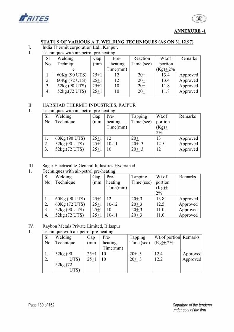
Page 130 of 162 Signature of the tenderer under seal of the firm
ANNEXURE -1
STATUS OF VARIOUS A.T. WELDING TECHNIQUES (AS ON 31.12.97)
I. India Thermit corporation Ltd., Kanpur.
1. Techniques with air-petrol pre-heating.
Sl
No
Welding
Techniqu
e
Gap
(mm
Pre-
heating
Time(mm)
Reaction
Time (sec)
Wt.of
portion
(Kg)+ 2%
Remarks
1.
2.
3.
4.
60Kg (90 UTS)
60Kg (72 UTS)
52kg.(90 UTS)
52kg.(72 UTS)
25+1
25+1
25+1
25+1
12
12
10
10
20+
20+
20+
20+
13.4
13.4
11.8
11.8
Approved
Approved
Approved
Approved
II. HARSHAD THERMIT INDUSTRIES, RAIPUR
1. Techniques with air-petrol pre-heating
Sl
No
Welding
Technique
Gap
(mm
Pre-
heating
Time(mm)
Tapping
Time (sec)
Wt.of
portion
(Kg)+
2%
Remarks
1.
2.
3.
60Kg (90 UTS)
52kg.(90 UTS)
52kg.(72 UTS)
25+1
25+1
25+1
12
10-11
10
20+
20+ 3
20+ 3
13
12.5
12
Approved
Approved
Approved
III. Sagar Electrical & General Industires Hyderabad
1. Techniques with air-petrol pre-heating
Sl
No
Welding
Technique
Gap
(mm
Pre-
heating
Time(mm)
Tapping
Time (sec)
Wt.of
portion
(Kg)+
2%
Remarks
1.
2.
3.
4.
60Kg (90 UTS)
60Kg (72 UTS)
52kg.(90 UTS)
52kg.(72 UTS)
25+1
25+1
25+1
25+1
12
10-12
10
10-11
20+ 3
20+ 3
20+ 3
20+ 3
13.8
12.5
11.0
11.0
Approved
Approved
Approved
Approved
IV. Raybon Metals Private Limited, Bilaspur
1. Technique with air-petrol pre-heating
Sl
No
Welding
Technique
Gap
(mm
Pre-
heating
Time(mm)
Tapping
Time (sec)
Wt.of portion
(Kg)+ 2%
Remarks
1.
2.
52kg.(90
UTS)
52kg.(72
UTS)
25+1
25+1
10
10
20+ 3
20+ 3
12.4
12.2
Approved
Approved
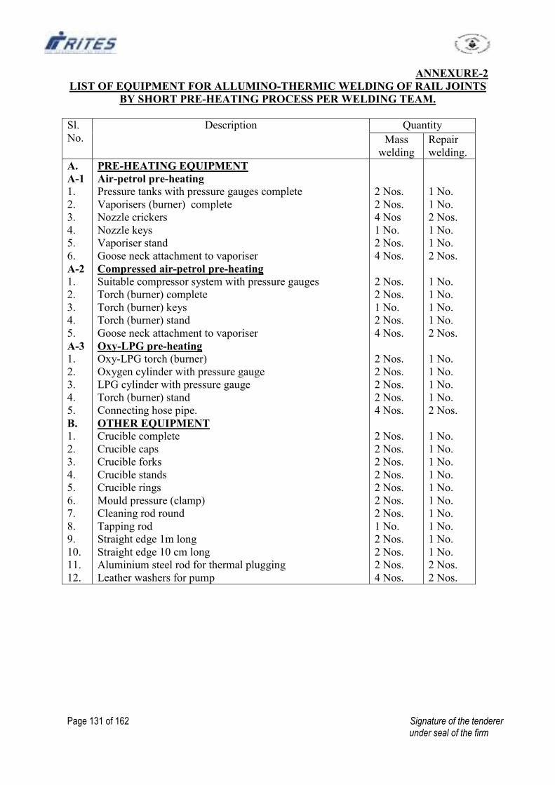
Page 131 of 162 Signature of the tenderer under seal of the firm
ANNEXURE-2
LIST OF EQUIPMENT FOR ALLUMINO-THERMIC WELDING OF RAIL JOINTS
BY SHORT PRE-HEATING PROCESS PER WELDING TEAM.
Sl.
No.
Description Quantity
Mass
welding
Repair
welding.
A.
A-1
1.
2.
3.
4.
5.
6.
A-2
1.
2.
3.
4.
5.
A-3
1.
2.
3.
4.
5.
B.
1.
2.
3.
4.
5.
6.
7.
8.
9.
10.
11.
12.
PRE-HEATING EQUIPMENT
Air-petrol pre-heating
Pressure tanks with pressure gauges complete
Vaporisers (burner) complete
Nozzle crickers
Nozzle keys
Vaporiser stand
Goose neck attachment to vaporiser
Compressed air-petrol pre-heating
Suitable compressor system with pressure gauges
Torch (burner) complete
Torch (burner) keys
Torch (burner) stand
Goose neck attachment to vaporiser
Oxy-LPG pre-heating
Oxy-LPG torch (burner)
Oxygen cylinder with pressure gauge
LPG cylinder with pressure gauge
Torch (burner) stand
Connecting hose pipe.
OTHER EQUIPMENT
Crucible complete
Crucible caps
Crucible forks
Crucible stands
Crucible rings
Mould pressure (clamp)
Cleaning rod round
Tapping rod
Straight edge 1m long
Straight edge 10 cm long
Aluminium steel rod for thermal plugging
Leather washers for pump
2 Nos.
2 Nos.
4 Nos
1 No.
2 Nos.
4 Nos.
2 Nos.
2 Nos.
1 No.
2 Nos.
4 Nos.
2 Nos.
2 Nos.
2 Nos.
2 Nos.
4 Nos.
2 Nos.
2 Nos.
2 Nos.
2 Nos.
2 Nos.
2 Nos.
2 Nos.
1 No.
2 Nos.
2 Nos.
2 Nos.
4 Nos.
1 No.
1 No.
2 Nos.
1 No.
1 No.
2 Nos.
1 No.
1 No.
1 No.
1 No.
2 Nos.
1 No.
1 No.
1 No.
1 No.
2 Nos.
1 No.
1 No.
1 No.
1 No.
1 No.
1 No.
1 No.
1 No.
1 No.
1 No.
2 Nos.
2 Nos.
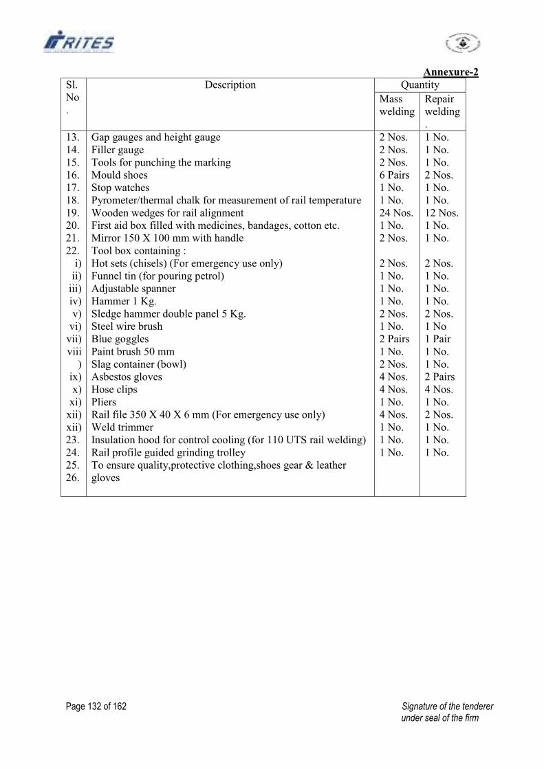
Page 132 of 162 Signature of the tenderer under seal of the firm
Annexure-2
Sl.
No
.
Description Quantity
Mass
welding
Repair
welding
.
13.
14.
15.
16.
17.
18.
19.
20.
21.
22.
i)
ii)
iii)
iv)
v)
vi)
vii)
viii
)
ix)
x)
xi)
xii)
xii)
23.
24.
25.
26.
Gap gauges and height gauge
Filler gauge
Tools for punching the marking
Mould shoes
Stop watches
Pyrometer/thermal chalk for measurement of rail temperature
Wooden wedges for rail alignment
First aid box filled with medicines, bandages, cotton etc.
Mirror 150 X 100 mm with handle
Tool box containing :
Hot sets (chisels) (For emergency use only)
Funnel tin (for pouring petrol)
Adjustable spanner
Hammer 1 Kg.
Sledge hammer double panel 5 Kg.
Steel wire brush
Blue goggles
Paint brush 50 mm
Slag container (bowl)
Asbestos gloves
Hose clips
Pliers
Rail file 350 X 40 X 6 mm (For emergency use only)
Weld trimmer
Insulation hood for control cooling (for 110 UTS rail welding)
Rail profile guided grinding trolley
To ensure quality,protective clothing,shoes gear & leather
gloves
2 Nos.
2 Nos.
2 Nos.
6 Pairs
1 No.
1 No.
24 Nos.
1 No.
2 Nos.
2 Nos.
1 No.
1 No.
1 No.
2 Nos.
1 No.
2 Pairs
1 No.
2 Nos.
4 Nos.
4 Nos.
1 No.
4 Nos.
1 No.
1 No.
1 No.
1 No.
1 No.
1 No.
2 Nos.
1 No.
1 No.
12 Nos.
1 No.
1 No.
2 Nos.
1 No.
1 No.
1 No.
2 Nos.
1 No
1 Pair
1 No.
1 No.
2 Pairs
4 Nos.
1 No.
2 Nos.
1 No.
1 No.
1 No.
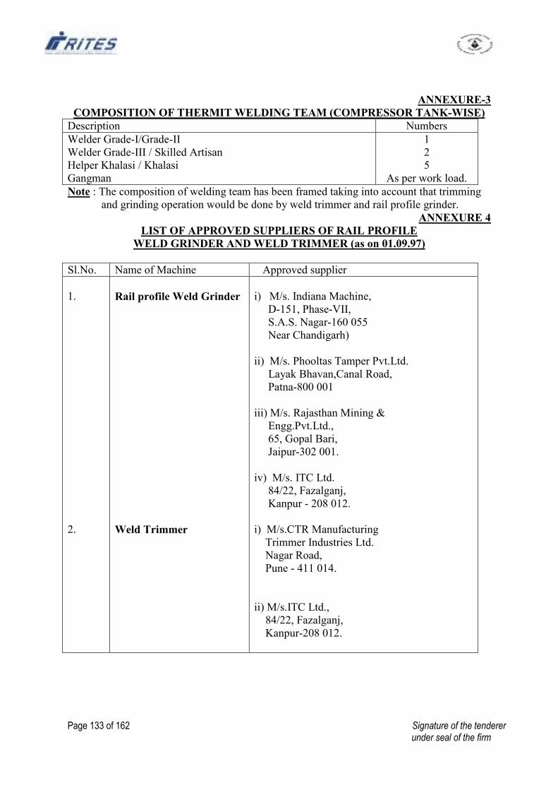
Page 133 of 162 Signature of the tenderer under seal of the firm
ANNEXURE-3
COMPOSITION OF THERMIT WELDING TEAM (COMPRESSOR TANK-WISE)
Description Numbers
Welder Grade-I/Grade-II
Welder Grade-III / Skilled Artisan
Helper Khalasi / Khalasi
Gangman
1
2
5
As per work load.
Note : The composition of welding team has been framed taking into account that trimming
and grinding operation would be done by weld trimmer and rail profile grinder.
ANNEXURE 4
LIST OF APPROVED SUPPLIERS OF RAIL PROFILE
WELD GRINDER AND WELD TRIMMER (as on 01.09.97)
Sl.No. Name of Machine Approved supplier
1.
2.
Rail profile Weld Grinder
Weld Trimmer
i) M/s. Indiana Machine,
D-151, Phase-VII,
S.A.S. Nagar-160 055
Near Chandigarh)
ii) M/s. Phooltas Tamper Pvt.Ltd.
Layak Bhavan,Canal Road,
Patna-800 001
iii) M/s. Rajasthan Mining &
Engg.Pvt.Ltd.,
65, Gopal Bari,
Jaipur-302 001.
iv) M/s. ITC Ltd.
84/22, Fazalganj,
Kanpur - 208 012.
i) M/s.CTR Manufacturing
Trimmer Industries Ltd.
Nagar Road,
Pune - 411 014.
ii) M/s.ITC Ltd.,
84/22, Fazalganj,
Kanpur-208 012.
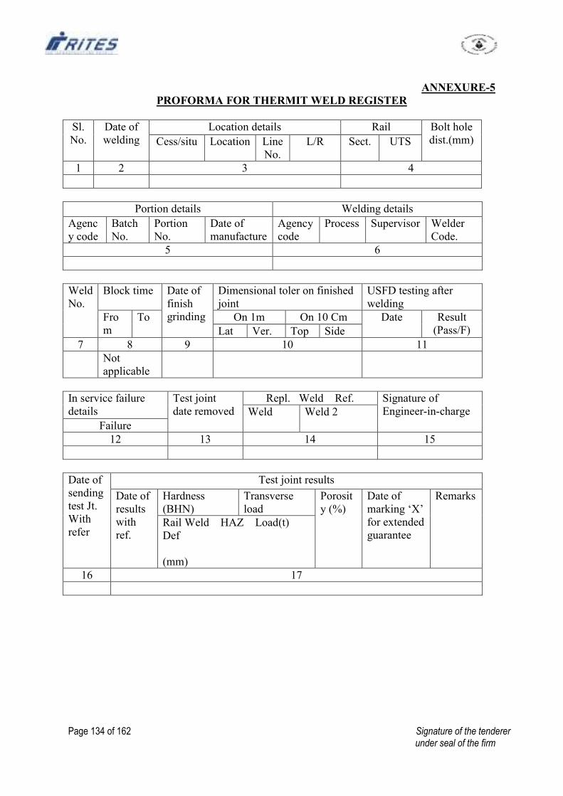
Page 134 of 162 Signature of the tenderer under seal of the firm
ANNEXURE-5
PROFORMA FOR THERMIT WELD REGISTER
Sl.
No.
Date of
welding
Location details Rail Bolt hole
dist.(mm) Cess/situ Location Line
No.
L/R Sect. UTS
1 2 3 4
Portion details Welding details
Agenc
y code
Batch
No.
Portion
No.
Date of
manufacture
Agency
code
Process Supervisor Welder
Code.
5 6
Weld
No.
Block time Date of
finish
grinding
Dimensional toler on finished
joint
USFD testing after
welding
Fro
m
To On 1m On 10 Cm Date Result
(Pass/F) Lat Ver. Top Side
7 8 9 10 11
Not
applicable
In service failure
details
Test joint
date removed
Repl. Weld Ref. Signature of
Engineer-in-charge Weld Weld 2
Failure
12 13 14 15
Date of
sending
test Jt.
With
refer
Test joint results
Date of
results
with
ref.
Hardness
(BHN)
Transverse
load
Porosit
y (%)
Date of
marking ‘X’
for extended
guarantee
Remarks
Rail Weld HAZ Load(t)
Def
(mm)
16 17
Page 135 of 162 Signature of the tenderer under seal of the firm
ANNEXURE-6
PROCEDURE FOR PAINTING OF WELD COLLAR FOR THERMIT WELDED
RAIL JOINTS TO PROTECT AGAINST NORMAL CORROSION
A. NEW WELDED JOINT.
1. Surface Preparation.
1.1 Remove dust, loose rust and mill scale by wire brushing.
1.2 Scrub welded area with water to make it free from slag and other water soluble
compounds. Make it dry.
2. Painting procedure
2.1 Apply one coat of ready mixed paint, brushing, bituminous black, lead free, acid,
alicali, water and chlorine resisting, conforming to IS:9862-1981 on the welded
area and 10 cm on either side.
2.2 After eight hours drying, apply a second coat of the same paint.
2.3 Painting should be carried out by brush only.
B. MAINTENANCE PAINTING (FOR OLD PAINTED JOINTS)
1. Surface preparation
1.1 Remove dust, dirt, and flaked paint from the welded joint by wire brushing.
1.2 Degrease the surface by petroleum hydrocarbon or any other suitable solvent, if
oil or grease is present. Allow it to dry.
2. Painting Procedure
2.1 Apply one coat of ready mixed paint, brushing, bituminous black, lead free, acid,
alkali and chlorine resistant to IS.9862-1981 or bituminous emulsion to IRS: P-30-
1996 on welded area and 10 cm on either side.
2.2 If required, a second coat of the same paint may be applied after a minimum of
eight hours drying.
2.3 Painting should be carried out by brush.
3. The list of approved manufacturers for the above quality of paints is issued every
year by the Director General(M&C),RDSO, Lucknow to Zonal Railways.
Page 136 of 162 Signature of the tenderer under seal of the firm
ANNEXURE-7
PROCEDURE FOR PAINTING OF WELD COLLAR FOR THERMIT WELDED
RAIL JOINTS TO PROTECT AGAINST SEVERE CORROSION
A. NEW WELDED JOINT
1. SURFACE PREPARATION
1.1 Remove dust, loose rust and mill scale by wire brushing.
1.2 Scrub welded area with water to make it free from slag and other water soluble
compounds. Make it dry.
2. Painting procedure
2.1 Apply one coat of high build epoxy paint (two pack) conforming to RDSO
specification No. M&C/PCN-111/88 on the welded area up to 10 cm on either
side.
NOTE:
1. The epoxy based paint recommended is a two pad system with a pot life of around
five hours. Hence, prepare only that much quantity of paint which can be consumed in
less than five hours.
2. The paint should be procured along with the thinner recommended by the
manufacturer of the paint. No other thinner i.e. kerosene oil, etc. should be used.
3. The painting shall be carried out by brush only. Brush shall be cleaned by the thinner
after use.
4. The list of probable suppliers is given below as per RDSO's letter No. M&C/PCN/
II/TR/3 dt. 13/14-5-1991.
i) M/s. Asian Paints (India) Ltd., iii) M/s. Goodlass Nerolac Paints
'Nirmal', 5th Floor, (P) Ltd., Nerolac House, Ganpat
Nariman Point, P.B. No.1546, Rao Kadaw Marg,
Mumbai-400421. Lower Parel, Mumbai-400013.
ii) M/s. Addison Paints & (iv) M/s. Shalimar Paints Limited,
Chemicals Ltd ‘Huzur Gardens’ 13, Camac St., Kolkata - 700071
Sembium, Chennai-600011.
(v) M/s. Berger Paints India Ltd.,
32, Chowringhee Road, Kol-71.
Page 137 of 162 Signature of the tenderer under seal of the firm
ANNEXURE 8
PROCEDURE FOR ULTRASONIC TESTING OF ALUMINO THERMIC RAIL
JOINTS
1. This procedure covers the requirement of ultrasonic testing of alumino thermic (AT)
welded rail joints immediately after execution of the weld.
2. General conditions of test
2.1 Surface preparation
After execution of the AT weld, the welded zone shall be dressed properly to
facilitate placement of probes and to avoid incidence of spurious signals on the
CRT. The rail table shall be dressed to obtain reasonably flat and smooth surface.
The flange and the web, up to a distance of 200 mm on either side of the weld collar
shall be thoroughly cleaned with a wire brush to ensure freedom from dust, dirt,
surface unevenness, etc.
2.2 Couplant:
Water/soft grease shall be used as couplant.
2.3 Sensitivity :
The equipment sensitivity shall be set for normal, 700 and 80
0 probes in accordance
with the procedure laid down in para 4. The sensitivity so adjusted shall be
considered as normal gain setting and shall be utilised during AT weld testing. The
sensitivity level shall not be altered during the course of testing.
3. Apparatus required
3.1 Equipment :
Any model of RDSO approved rail tester shall be considered suitable for testing of
AT welded rail joints.
3.2 Probes :
During ultrasonic examination of AT welded joints, the following probes shall be
utilised :
(a) Normal (00), 4MHz Double crystal fitted in trolley
(b) 700,2 MHz, Double crystal fitted in trolley
(c) 800, 1.25 MHz Single crystal for hand probing.
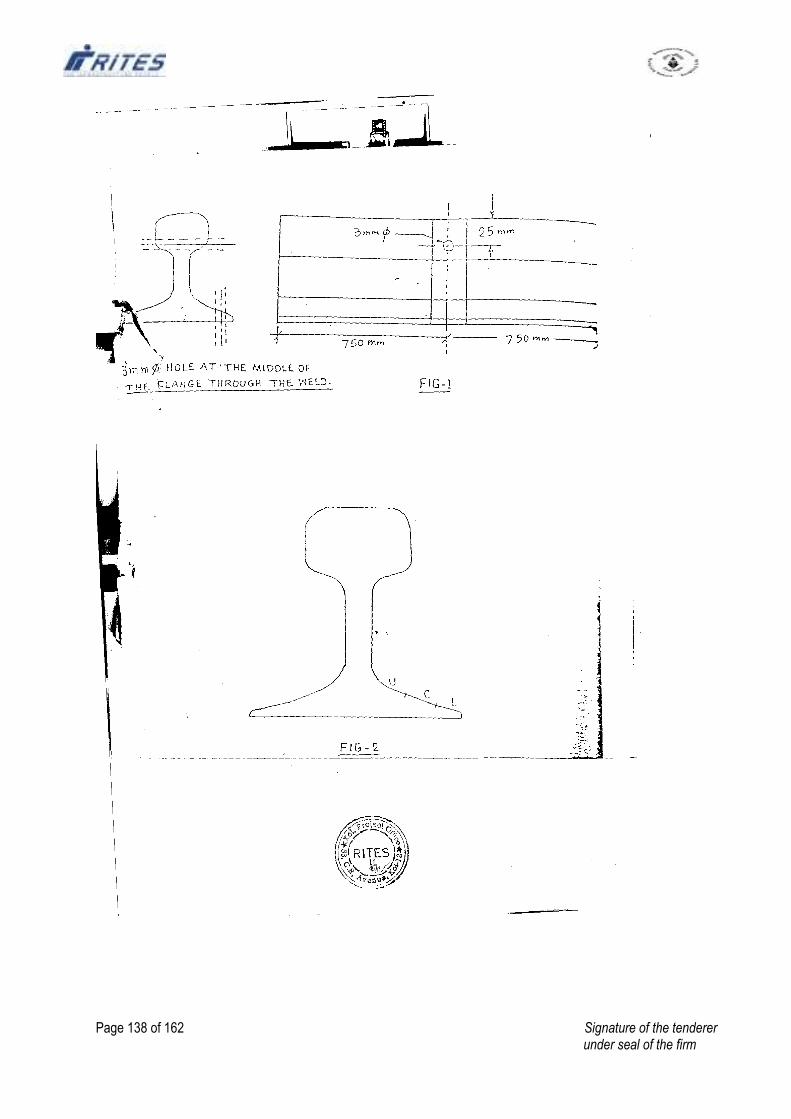
Page 138 of 162 Signature of the tenderer under seal of the firm
Page 139 of 162 Signature of the tenderer under seal of the firm
3.3 Cable :
Cable : One co-axial cable of suitable length for connecting 800 probe to flaw
detector shall be used. The length should not exceed more than 5m.
4. Sensitivity setting procedure
4.1 Calibration :
The equipment shall be set for a depth range of 250 mm by manipulating the depth
control knob suitably. Each main scale division, therefore, shall correspond to 25
mm.
4.2 Test rail
The sensitivity of the ultrasonic equipment shall be set with the help of a standard
AT welded rail piece of 1.5 m length having a simulated flaw at standard locations
as shown in Fig.1.
4.3 Alignment of probes:
Alignment of normal and 70 o probes fitted with the trolley may be checked by
placing the rail tester on the test rail using water/oil as a couplant and ensuring that
the probes travel along the vertical axis of the rail.
4.4 Sensitivity setting for 700 probes
4.4.1 Place the trolley on the test rails shown in Fig.1. Keep the switches of all the probes
in off positions and turn the potentiometer knobs of all the probes to 50% of their
highest working range.
4.4.2 Switch on only 700 towards probe and move the equipment towards the drilled hole
of 3 mm dia in rail head. When the probe is just in the reflecting range, a pulse
corresponding to the hole shall appear on the screen which during onward traveling
shall show higher amplitude. The pulse shall appear moving from right to left. The
equipment should be progressively moved forward till maximum height of the
pulse is obtained. At this location the height of the pulse shall be adjusted to 50% of
full screen height by suitably manipulation of the gain knob.
4.4.3 The forward probe shall be switched off and the 70% backward probe shall now be
switched on. In this case a flaw signal shall appear moving from left to right. The
signal height in this position shall also be adjusted to 60% of full screen height. This
can be accomplished through suitable manipulation of relevant potentiometer.
4.4.4 The sensitivity setting for the normal problem has to be done while keeping all other
probes in off position Switch on only the normal probe and bring if above 3 mm dia
hole drilled in the head of the test rail. Manipulate the potentiometer control knob to
obtain echo eight of 60% of full screen height at 1.0 division horizontal scale.
4.4.5 800 probe shall be connected to the socket available in the ultrasonic equipment. The
selectors switch may be set to single crystal mode. Move the probe towards the 3 mm
dia hole drilled at the middle of the flange through in the AT weld and manipulate
knobs to obtain a 60% full screen height on the CRT.
Page 140 of 162 Signature of the tenderer under seal of the firm
5. Criteria for defect classification
5.1 Any flaw signal obtained by normal probe of 40% height or more from head location
shall be treated as a defective AT welded joint and any flaw signal obtained from
the normal probe either from the web or the foot location shall also be a cause for
rejection of the AT weld.
5.2 In the case of lack of fusion, inclusions, blow holes, etc. in the rail head, moving
signal shall be obtained while testing with 700 probe. The position of onset of the
signal and its corresponding range on the horizontal screen as well as their
maximum amplitude shall be recorded.
A welded joint showing the moving signal of 40% or more of the full screen height
shall be considered as a defective welded joint.
5.3 800 probe shall be placed on the flange at a distance of 180 mm corresponding to
position 'L' in Fig.2 such that ultrasonic waves are directed towards the weld. The
probe shall thereafter be moved slowly in zigzag patter towards the weld. A welded
joint showing a flaw echo of 40% vertical height or more with the stipulated gain
setting shall be treated as a defective welded joint. Similar testing shall be carried
out of 'C' and 'U' regions as shown in Fig.2. In these cases also the criteria for
rejection shall remain the same.
6. The defective joints based on the criteria mentioned at para 5 shall not be allowed to
remain in service and shall be cropped, re-welded and tested again. This execution
shall be done by the contractor free of cost. The re-welded joints shall be scanned
ultrasonically again with the same set of acceptance criteria to ensure freedom any
harmful defects.
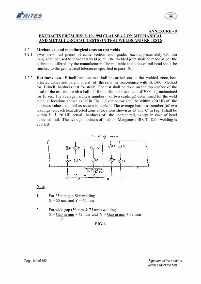
Page 141 of 162 Signature of the tenderer under seal of the firm
ANNEXURE - 9
EXTRACTS FROM IRS: T-19-1994 CLAUSE 4.2 ON MECHANICAL
AND METALLURGICAL TESTS ON TEST WELDS AND RETESTS
4.2 Mechanical and metallurgical tests on test welds
4.2.1 Two new rail pieces of same section and grade, each approximately 750 mm
long, shall be used to make test weld joint. The welded joint shall be made as per the
technique offered by the manufacturer. The rail table and sides of rail head shall be
finished to the geometrical tolerances specified in para 18.1
4.2.2 Hardness test : Brinell hardness test shall be carried out at the welded zone, heat
affected zones and parent metal of the rails in accordance with IS:1500 "Method
for Brinell hardness test for steel". The test shall be done on the top surface of the
head of the test weld with a ball of 10 mm dia and a test load of 3000 kg maintained
for 10 sec. The average hardness number ( of two readings) determined for the weld
metal at locations shown as 'A' in Fig. 1 given below shall be within +20 HB of the
hardness values of rail as shown in table 1. The average hardness number (of two
readings) on each heat affected zone at locations shown as 'B' and 'C' in Fig. 1 shall be � �within + 20 HB actual hardness of the parent rail, except in case of head
hardened rail. The average hardness of medium Manganese IRS-T-18 for welding is
230 HB.
Note :
1. For 25 mm gap Skv welding
X = 55 mm and Y = 45 mm
2. For wide gap (50 mm & 75 mm) welding
X = Gap in mm + 42 mm and Y = Gap in mm + 32 mm
2
FIG.1.
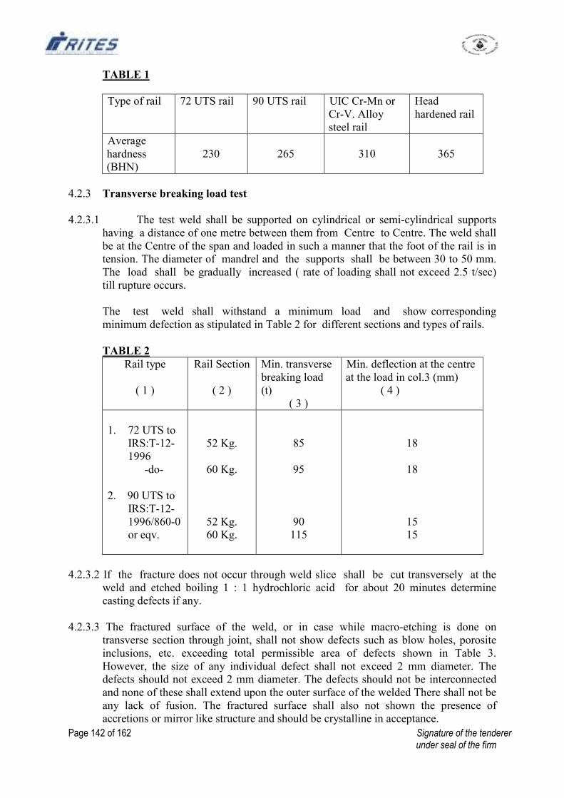
Page 142 of 162 Signature of the tenderer under seal of the firm
TABLE 1
Type of rail 72 UTS rail 90 UTS rail UIC Cr-Mn or
Cr-V. Alloy
steel rail
Head
hardened rail
Average
hardness
(BHN)
230
265
310
365
4.2.3 Transverse breaking load test
4.2.3.1 The test weld shall be supported on cylindrical or semi-cylindrical supports
having a distance of one metre between them from Centre to Centre. The weld shall
be at the Centre of the span and loaded in such a manner that the foot of the rail is in
tension. The diameter of mandrel and the supports shall be between 30 to 50 mm.
The load shall be gradually increased ( rate of loading shall not exceed 2.5 t/sec)
till rupture occurs.
The test weld shall withstand a minimum load and show corresponding
minimum defection as stipulated in Table 2 for different sections and types of rails.
TABLE 2
Rail type
( 1 )
Rail Section
( 2 )
Min. transverse
breaking load
(t)
( 3 )
Min. deflection at the centre
at the load in col.3 (mm)
( 4 )
1. 72 UTS to
IRS:T-12-
1996
-do-
2. 90 UTS to
IRS:T-12-
1996/860-0
or eqv.
52 Kg.
60 Kg.
52 Kg.
60 Kg.
85
95
90
115
18
18
15
15
4.2.3.2 If the fracture does not occur through weld slice shall be cut transversely at the
weld and etched boiling 1 : 1 hydrochloric acid for about 20 minutes determine
casting defects if any.
4.2.3.3 The fractured surface of the weld, or in case while macro-etching is done on
transverse section through joint, shall not show defects such as blow holes, porosite
inclusions, etc. exceeding total permissible area of defects shown in Table 3.
However, the size of any individual defect shall not exceed 2 mm diameter. The
defects should not exceed 2 mm diameter. The defects should not be interconnected
and none of these shall extend upon the outer surface of the welded There shall not be
any lack of fusion. The fractured surface shall also not shown the presence of
accretions or mirror like structure and should be crystalline in acceptance.
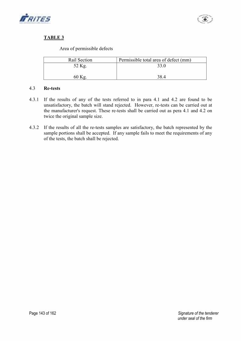
Page 143 of 162 Signature of the tenderer under seal of the firm
TABLE 3
Area of permissible defects
Rail Section Permissible total area of defect (mm)
52 Kg.
60 Kg.
33.0
38.4
4.3 Re-tests
4.3.1 If the results of any of the tests referred to in para 4.1 and 4.2 are found to be
unsatisfactory, the batch will stand rejected. However, re-tests can be carried out at
the manufacturer's request. These re-tests shall be carried out as pera 4.1 and 4.2 on
twice the original sample size.
4.3.2 If the results of all the re-tests samples are satisfactory, the batch represented by the
sample portions shall be accepted. If any sample fails to meet the requirements of any
of the tests, the batch shall be rejected.
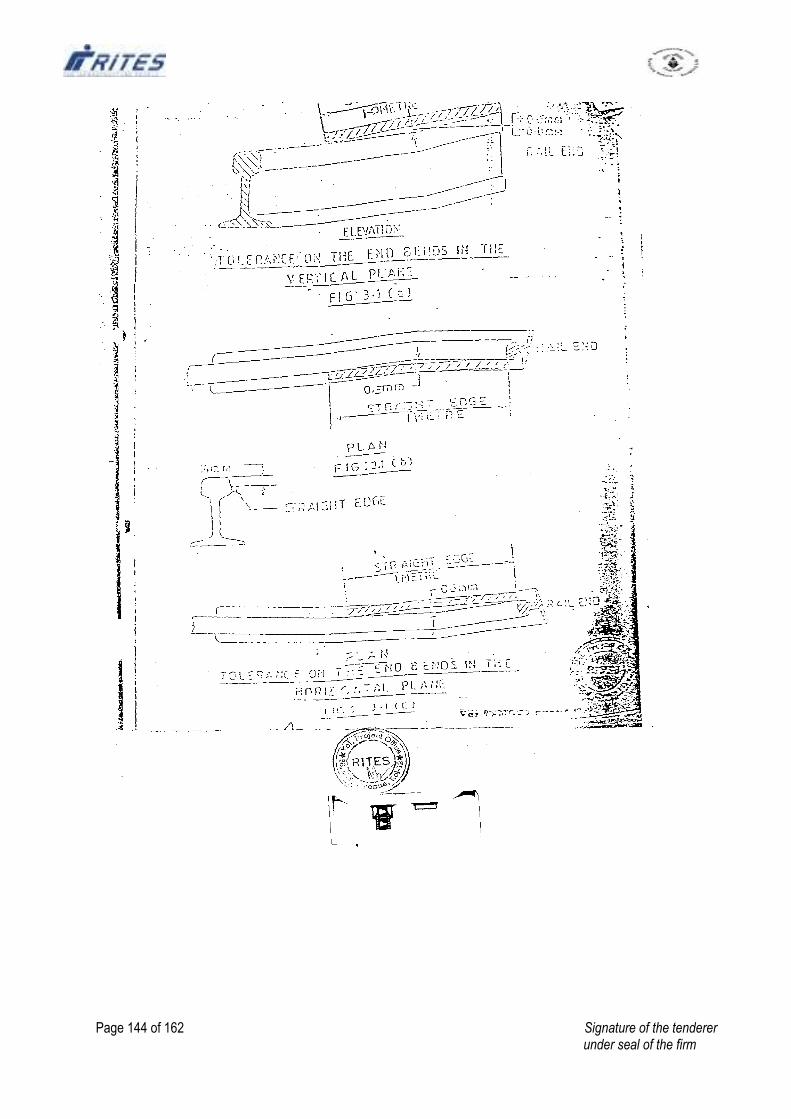
Page 144 of 162 Signature of the tenderer under seal of the firm
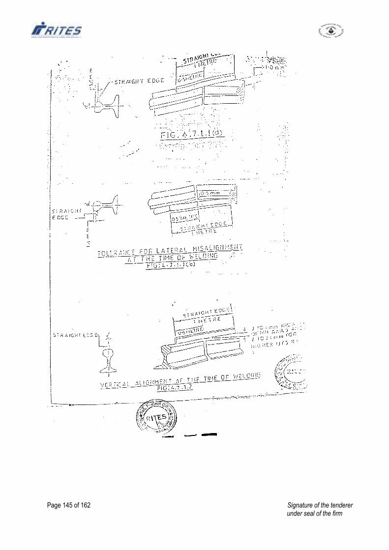
Page 145 of 162 Signature of the tenderer under seal of the firm
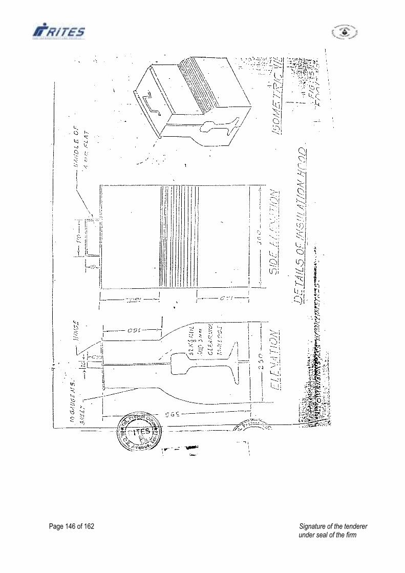
Page 146 of 162 Signature of the tenderer under seal of the firm
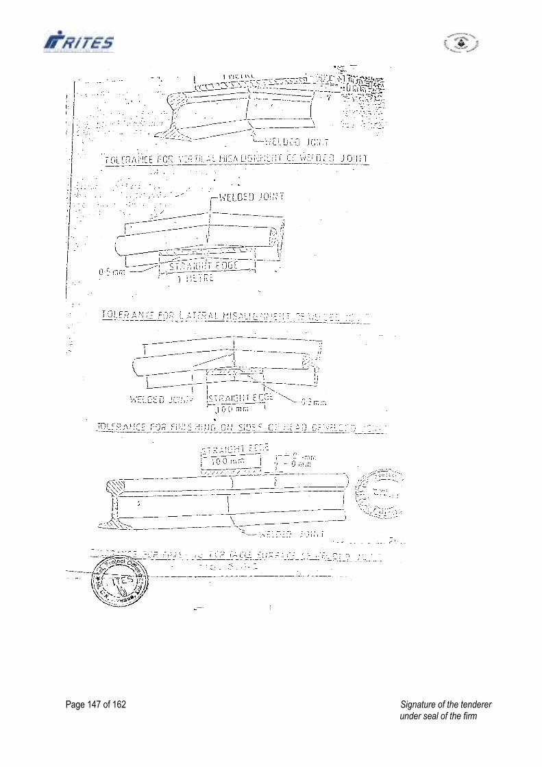
Page 147 of 162 Signature of the tenderer under seal of the firm
Page 148 of 162 Signature of the tenderer under seal of the firm
SECTION - 6
DRAWINGS
NOT ENCLOSED
Page 149 of 162 Signature of the tenderer under seal of the firm
PART – 2
FINANCIAL BID
SCHEDULE (BILL) OF QUANTITIES
Page 150 of 162 Signature of the tenderer under seal of the firm
PART - 2
FINANCIAL BID
SCHEDULE (BILL OF QUANTITIES)
NAME OF WORK:- Balance work of Laying & Linking of Railway track including
supply of ballast & other P. Way materials in connection with construction
management and arrangement of new Railway Siding for rapid loading system at
Junadih Siding of SECL at Gevra, Dist. Korba (C.G).
POINTS TO BE NOTED WHILE QUOTING RATES
1) Where Tender has been invited on Percentage Rate basis, percentages on the Estimated
Cost (whether above or below) are to be quoted for each of the Schedules.
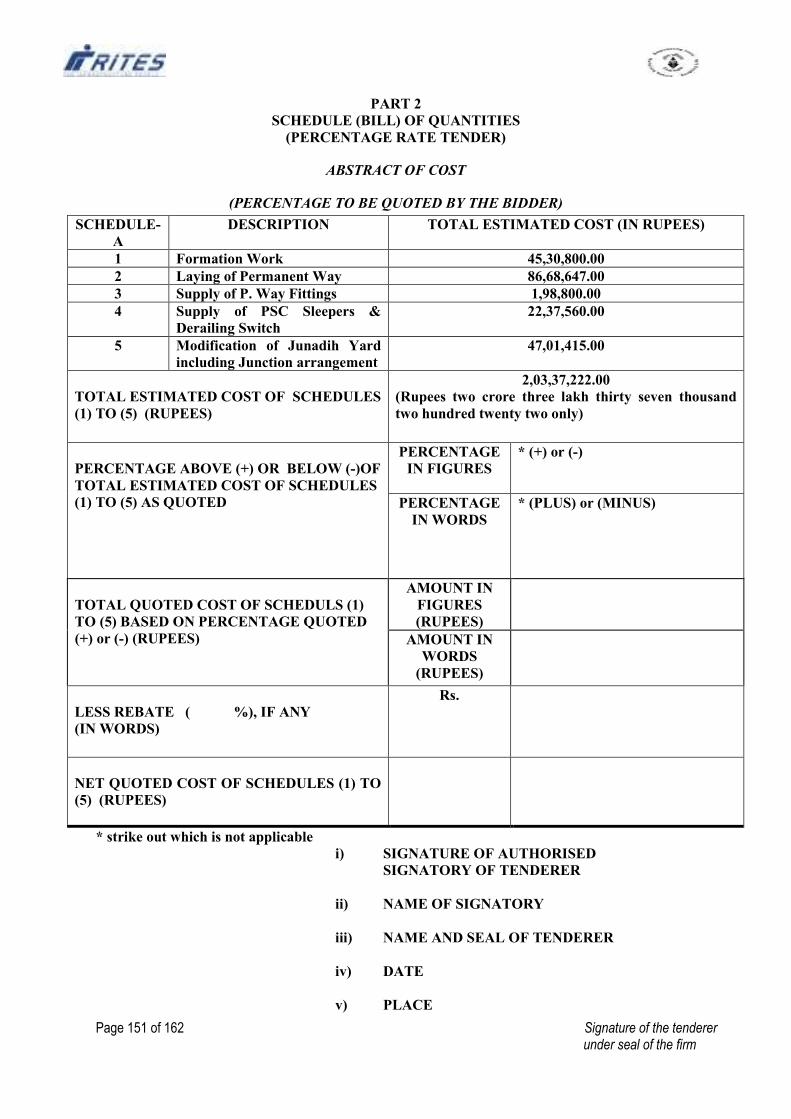
Page 151 of 162 Signature of the tenderer under seal of the firm
PART 2
SCHEDULE (BILL) OF QUANTITIES
(PERCENTAGE RATE TENDER)
ABSTRACT OF COST
(PERCENTAGE TO BE QUOTED BY THE BIDDER)
SCHEDULE-
A
DESCRIPTION TOTAL ESTIMATED COST (IN RUPEES)
1 Formation Work 45,30,800.00
2 Laying of Permanent Way 86,68,647.00
3 Supply of P. Way Fittings 1,98,800.00
4 Supply of PSC Sleepers &
Derailing Switch
22,37,560.00
5 Modification of Junadih Yard
including Junction arrangement
47,01,415.00
TOTAL ESTIMATED COST OF SCHEDULES
(1) TO (5) (RUPEES)
2,03,37,222.00
(Rupees two crore three lakh thirty seven thousand
two hundred twenty two only)
PERCENTAGE ABOVE (+) OR BELOW (-)OF
TOTAL ESTIMATED COST OF SCHEDULES
(1) TO (5) AS QUOTED
PERCENTAGE
IN FIGURES
* (+) or (-)
PERCENTAGE
IN WORDS
* (PLUS) or (MINUS)
TOTAL QUOTED COST OF SCHEDULS (1)
TO (5) BASED ON PERCENTAGE QUOTED
(+) or (-) (RUPEES)
AMOUNT IN
FIGURES
(RUPEES)
AMOUNT IN
WORDS
(RUPEES)
LESS REBATE ( %), IF ANY
(IN WORDS)
Rs.
NET QUOTED COST OF SCHEDULES (1) TO
(5) (RUPEES)
* strike out which is not applicable
i) SIGNATURE OF AUTHORISED
SIGNATORY OF TENDERER
ii) NAME OF SIGNATORY
iii) NAME AND SEAL OF TENDERER
iv) DATE
v) PLACE
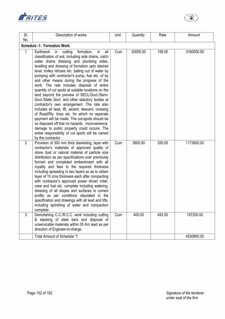
Page 152 of 162 Signature of the tenderer under seal of the firm
Sl. No.
Description of works Unit Quantity Rate Amount
Schedule -1: Formation Work.
1 Earthwork in cutting formation, in all classification of soil, including side drains, catch water drains dressing and plumbing sides, levelling and dressing of formation upto desired level, trolley refuses etc. bailing out of water by pumping with contractor's pump, fuel etc. of by and other means during the progress of the work. The rate includes disposal of entire quantity of cut spoils at suitable locations on the land beyond the preview of SECL/Govt./Semi-Govt./State Govt. and other statutory bodies at contractor's own arrangement .The rate also includes all lead, lift, ascent, descent, crossing of Road/Rly. lines etc. for which no separate payment will be made. The cut-spoils should be so disposed off that no hazards , inconvenience, damage to public property could occure. The entire responsibility of cut spoils will be owned by the contractor.
Cum 20000.00 158.00 3160000.00
2 Provision of 300 mm thick blanketing, layer with contractor’s materials of approved quality of stone dust or natural material of particle size distribution as per specifications over previously formed and completed embankment with all royality and fees to the required thickness including spreading in two layers so as to obtain layer of 15 cms thickness each after compacting with contractor’s approved power driven roller, crew and fuel etc. complete including watering, dressing of all slopes and surfaces to correct profile as per conditions stipulated in the specification and drawings with all lead and lifts, including sprinkling of water and compaction complete.
Cum 3600.00 326.00 1173600.00
3 Demolishing C.C./R.C.C. work including cutting & stacking of steel bars and disposal of unservicable materials within 05 Km lead as per direction of Engineer-in-charge.
Cum 400.00 493.00 197200.00
Total Amount of Schedule '1' 4530800.00
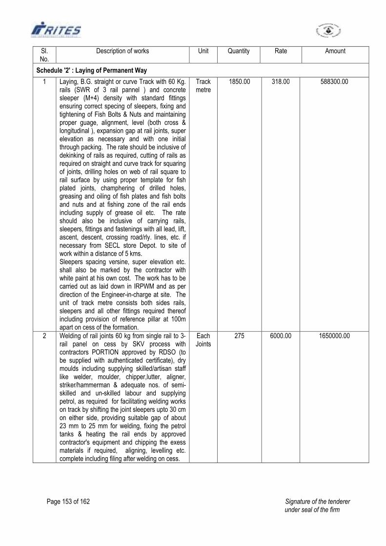
Page 153 of 162 Signature of the tenderer under seal of the firm
Sl. No.
Description of works Unit Quantity Rate Amount
Schedule '2' : Laying of Permanent Way
1 Laying, B.G. straight or curve Track with 60 Kg. rails (SWR of 3 rail pannel ) and concrete sleeper (M+4) density with standard fittings ensuring correct specing of sleepers, fixing and tightening of Fish Bolts & Nuts and maintaining proper guage, alignment, level (both cross & longitudinal ), expansion gap at rail joints, super elevation as necessary and with one initial through packing. The rate should be inclusive of dekinking of rails as required, cutting of rails as required on straight and curve track for squaring of joints, drilling holes on web of rail square to rail surface by using proper template for fish plated joints, champhering of drilled holes, greasing and oiling of fish plates and fish bolts and nuts and at fishing zone of the rail ends including supply of grease oil etc. The rate should also be inclusive of carrying rails, sleepers, fittings and fastenings with all lead, lift, ascent, descent, crossing road/rly. lines, etc. if necessary from SECL store Depot. to site of work within a distance of 5 kms. Sleepers spacing versine, super elevation etc. shall also be marked by the contractor with white paint at his own cost. The work has to be carried out as laid down in IRPWM and as per direction of the Engineer-in-charge at site. The unit of track metre consists both sides rails, sleepers and all other fittings required thereof including provision of reference pillar at 100m apart on cess of the formation.
Track metre
1850.00 318.00 588300.00
2 Welding of rail joints 60 kg from single rail to 3-rail panel on cess by SKV process with contractors PORTION approved by RDSO (to be supplied with authenticated certificate), dry moulds including supplying skilled/artisan staff like welder, moulder, chipper,lutter, aligner, striker/hammerman & adequate nos. of semi-skilled and un-skilled labour and supplying petrol, as required for facilitating welding works on track by shifting the joint sleepers upto 30 cm on either side, providing suitable gap of about 23 mm to 25 mm for welding, fixing the petrol tanks & heating the rail ends by approved contractor's equipment and chipping the exess materials if required, aligning, levelling etc. complete including filing after welding on cess.
Each Joints
275 6000.00 1650000.00
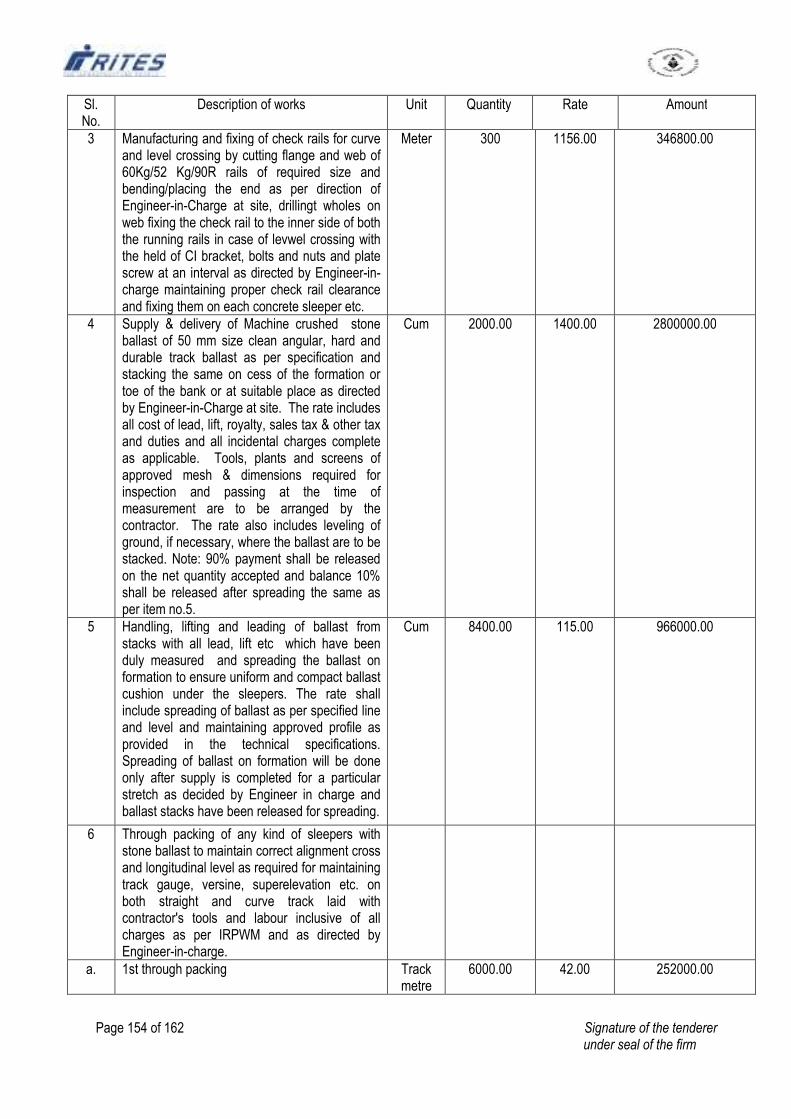
Page 154 of 162 Signature of the tenderer under seal of the firm
Sl. No.
Description of works Unit Quantity Rate Amount
3 Manufacturing and fixing of check rails for curve and level crossing by cutting flange and web of 60Kg/52 Kg/90R rails of required size and bending/placing the end as per direction of Engineer-in-Charge at site, drillingt wholes on web fixing the check rail to the inner side of both the running rails in case of levwel crossing with the held of CI bracket, bolts and nuts and plate screw at an interval as directed by Engineer-in-charge maintaining proper check rail clearance and fixing them on each concrete sleeper etc.
Meter 300 1156.00 346800.00
4 Supply & delivery of Machine crushed stone ballast of 50 mm size clean angular, hard and durable track ballast as per specification and stacking the same on cess of the formation or toe of the bank or at suitable place as directed by Engineer-in-Charge at site. The rate includes all cost of lead, lift, royalty, sales tax & other tax and duties and all incidental charges complete as applicable. Tools, plants and screens of approved mesh & dimensions required for inspection and passing at the time of measurement are to be arranged by the contractor. The rate also includes leveling of ground, if necessary, where the ballast are to be stacked. Note: 90% payment shall be released on the net quantity accepted and balance 10% shall be released after spreading the same as per item no.5.
Cum 2000.00 1400.00 2800000.00
5 Handling, lifting and leading of ballast from stacks with all lead, lift etc which have been duly measured and spreading the ballast on formation to ensure uniform and compact ballast cushion under the sleepers. The rate shall include spreading of ballast as per specified line and level and maintaining approved profile as provided in the technical specifications. Spreading of ballast on formation will be done only after supply is completed for a particular stretch as decided by Engineer in charge and ballast stacks have been released for spreading.
Cum 8400.00 115.00 966000.00
6 Through packing of any kind of sleepers with stone ballast to maintain correct alignment cross and longitudinal level as required for maintaining track gauge, versine, superelevation etc. on both straight and curve track laid with contractor's tools and labour inclusive of all charges as per IRPWM and as directed by Engineer-in-charge.
a. 1st through packing Track metre
6000.00 42.00 252000.00
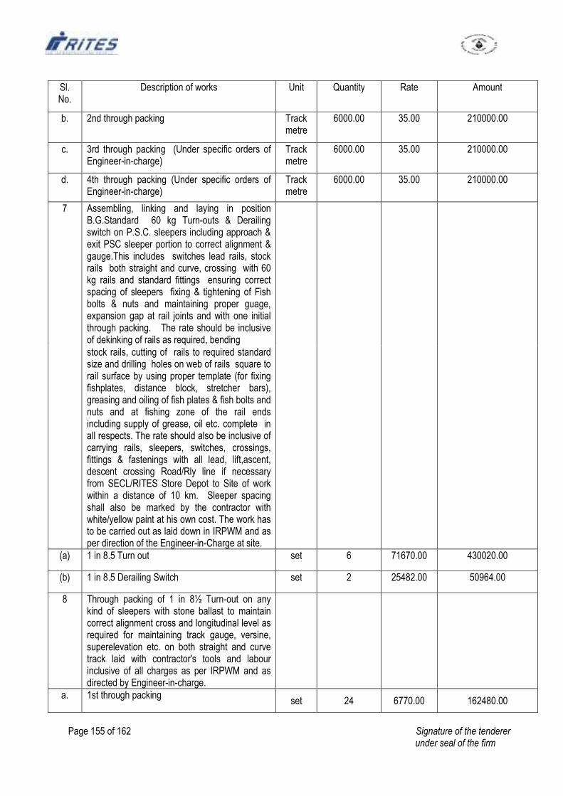
Page 155 of 162 Signature of the tenderer under seal of the firm
Sl. No.
Description of works Unit Quantity Rate Amount
b. 2nd through packing Track metre
6000.00 35.00 210000.00
c. 3rd through packing (Under specific orders of Engineer-in-charge)
Track metre
6000.00 35.00 210000.00
d. 4th through packing (Under specific orders of Engineer-in-charge)
Track metre
6000.00 35.00 210000.00
7 Assembling, linking and laying in position B.G.Standard 60 kg Turn-outs & Derailing switch on P.S.C. sleepers including approach & exit PSC sleeper portion to correct alignment & gauge.This includes switches lead rails, stock rails both straight and curve, crossing with 60 kg rails and standard fittings ensuring correct spacing of sleepers fixing & tightening of Fish bolts & nuts and maintaining proper guage, expansion gap at rail joints and with one initial through packing. The rate should be inclusive of dekinking of rails as required, bending
stock rails, cutting of rails to required standard size and drilling holes on web of rails square to rail surface by using proper template (for fixing fishplates, distance block, stretcher bars), greasing and oiling of fish plates & fish bolts and nuts and at fishing zone of the rail ends including supply of grease, oil etc. complete in all respects. The rate should also be inclusive of carrying rails, sleepers, switches, crossings, fittings & fastenings with all lead, lift,ascent, descent crossing Road/Rly line if necessary from SECL/RITES Store Depot to Site of work within a distance of 10 km. Sleeper spacing shall also be marked by the contractor with white/yellow paint at his own cost. The work has to be carried out as laid down in IRPWM and as per direction of the Engineer-in-Charge at site.
(a) 1 in 8.5 Turn out set 6 71670.00 430020.00
(b) 1 in 8.5 Derailing Switch set 2 25482.00 50964.00
8 Through packing of 1 in 8½ Turn-out on any kind of sleepers with stone ballast to maintain correct alignment cross and longitudinal level as required for maintaining track gauge, versine, superelevation etc. on both straight and curve track laid with contractor's tools and labour inclusive of all charges as per IRPWM and as directed by Engineer-in-charge.
a. 1st through packing set 24 6770.00 162480.00
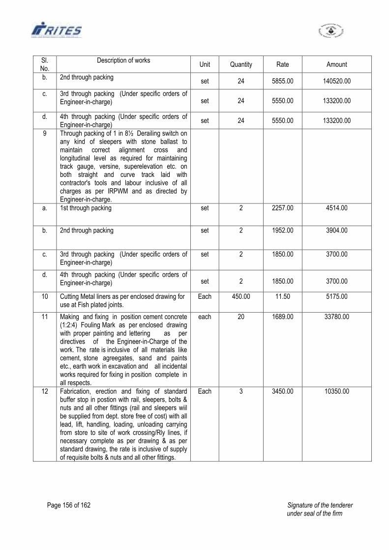
Page 156 of 162 Signature of the tenderer under seal of the firm
Sl. No.
Description of works Unit Quantity Rate Amount
b. 2nd through packing set 24 5855.00 140520.00
c. 3rd through packing (Under specific orders of Engineer-in-charge) set 24 5550.00 133200.00
d. 4th through packing (Under specific orders of Engineer-in-charge)
set 24 5550.00 133200.00
9 Through packing of 1 in 8½ Derailing switch on any kind of sleepers with stone ballast to maintain correct alignment cross and longitudinal level as required for maintaining track gauge, versine, superelevation etc. on both straight and curve track laid with contractor's tools and labour inclusive of all charges as per IRPWM and as directed by Engineer-in-charge.
a. 1st through packing set 2 2257.00 4514.00
b. 2nd through packing set 2 1952.00 3904.00
c. 3rd through packing (Under specific orders of Engineer-in-charge)
set 2 1850.00 3700.00
d. 4th through packing (Under specific orders of Engineer-in-charge) set 2 1850.00 3700.00
10 Cutting Metal liners as per enclosed drawing for use at Fish plated joints.
Each 450.00 11.50 5175.00
11 Making and fixing in position cement concrete (1:2:4) Fouling Mark as per enclosed drawing with proper painting and lettering as per directives of the Engineer-in-Charge of the work. The rate is inclusive of all materials like cement, stone agreegates, sand and paints etc., earth work in excavation and all incidental works required for fixing in position complete in all respects.
each 20 1689.00 33780.00
12 Fabrication, erection and fixing of standard buffer stop in postion with rail, sleepers, bolts & nuts and all other fittings (rail and sleepers wiil be supplied from dept. store free of cost) with all lead, lift, handling, loading, unloading carrying from store to site of work crossing/Rly lines, if necessary complete as per drawing & as per standard drawing, the rate is inclusive of supply of requisite bolts & nuts and all other fittings.
Each 3 3450.00 10350.00
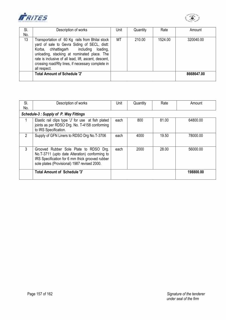
Page 157 of 162 Signature of the tenderer under seal of the firm
Sl. No.
Description of works Unit Quantity Rate Amount
13 Transportation of 60 Kg rails from Bhilai stock yard of sale to Gevra Siding of SECL, distt: Korba, chhattisgarh including loading, unloading, stacking at nominated place. The rate is inclusive of all lead, lift, ascent, descent, crossing road/Rly lines, if necessary complete in all respect.
MT 210.00 1524.00 320040.00
Total Amount of Schedule '2' 8668647.00
Sl. No.
Description of works Unit Quantity Rate Amount
Schedule-3 : Supply of P. Way Fittings
1 Elastic rail clips type 'J' for use at fish plated joints as per RDSO Drg. No. T-4158 conforming to IRS Specification.
each 800 81.00 64800.00
2 Supply of GFN Liners to RDSO Drg No.T-3706 each 4000 19.50 78000.00
3 Grooved Rubber Sole Plate to RDSO Drg. No.T-3711 (upto date Alteration) conforming to IRS Specification for 6 mm thick grooved rubber sole plates (Provisional) 1987 revised 2000.
each 2000 28.00 56000.00
Total Amount of Schedule '3' 198800.00
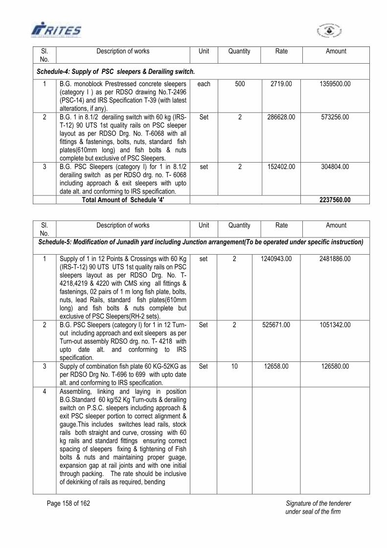
Page 158 of 162 Signature of the tenderer under seal of the firm
Sl. No.
Description of works Unit Quantity Rate Amount
Schedule-4: Supply of PSC sleepers & Derailing switch.
1 B.G. monoblock Prestressed concrete sleepers (category I ) as per RDSO drawing No.T-2496 (PSC-14) and IRS Specification T-39 (with latest alterations, if any).
each 500 2719.00 1359500.00
2 B.G. 1 in 8.1/2 derailing switch with 60 kg (IRS-T-12) 90 UTS 1st quality rails on PSC sleeper layout as per RDSO Drg. No. T-6068 with all fittings & fastenings, bolts, nuts, standard fish plates(610mm long) and fish bolts & nuts complete but exclusive of PSC Sleepers.
Set 2 286628.00 573256.00
3 B.G. PSC Sleepers (category I) for 1 in 8.1/2 derailing switch as per RDSO drg. no. T- 6068 including approach & exit sleepers with upto date alt. and conforming to IRS specification.
set 2 152402.00 304804.00
Total Amount of Schedule '4' 2237560.00
Sl. No.
Description of works Unit Quantity Rate Amount
Schedule-5: Modification of Junadih yard including Junction arrangement(To be operated under specific instruction)
1 Supply of 1 in 12 Points & Crossings with 60 Kg (IRS-T-12) 90 UTS UTS 1st quality rails on PSC sleepers layout as per RDSO Drg. No. T-4218,4219 & 4220 with CMS xing all fittings & fastenings, 02 pairs of 1 m long fish plate, bolts, nuts, lead Rails, standard fish plates(610mm long) and fish bolts & nuts complete but exclusive of PSC Sleepers(RH-2 sets).
set 2 1240943.00 2481886.00
2 B.G. PSC Sleepers (category I) for 1 in 12 Turn-out including approach and exit sleepers as per Turn-out assembly RDSO drg. no. T- 4218 with upto date alt. and conforming to IRS specification.
Set 2 525671.00 1051342.00
3 Supply of combination fish plate 60 KG-52KG as per RDSO Drg No. T-696 to 699 with upto date alt. and conforming to IRS specification.
Set 10 12658.00 126580.00
4 Assembling, linking and laying in position B.G.Standard 60 kg/52 Kg Turn-outs & derailing switch on P.S.C. sleepers including approach & exit PSC sleeper portion to correct alignment & gauge.This includes switches lead rails, stock rails both straight and curve, crossing with 60 kg rails and standard fittings ensuring correct spacing of sleepers fixing & tightening of Fish bolts & nuts and maintaining proper guage, expansion gap at rail joints and with one initial through packing. The rate should be inclusive of dekinking of rails as required, bending
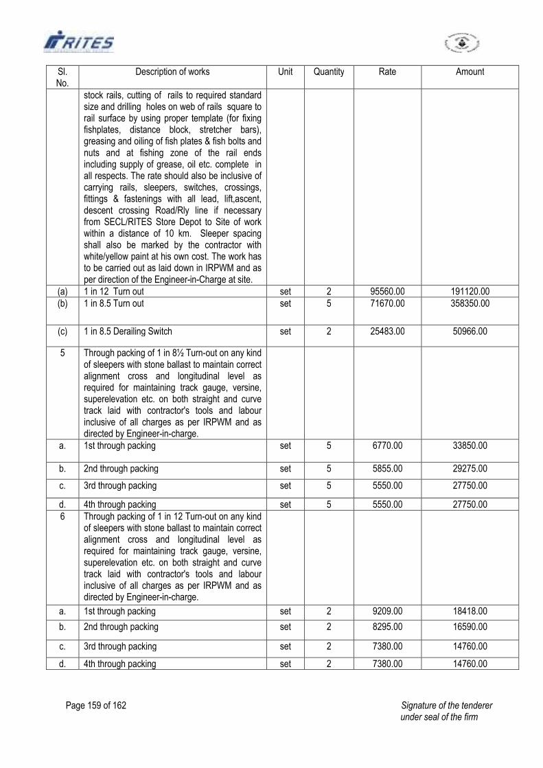
Page 159 of 162 Signature of the tenderer under seal of the firm
Sl. No.
Description of works Unit Quantity Rate Amount
stock rails, cutting of rails to required standard size and drilling holes on web of rails square to rail surface by using proper template (for fixing fishplates, distance block, stretcher bars), greasing and oiling of fish plates & fish bolts and nuts and at fishing zone of the rail ends including supply of grease, oil etc. complete in all respects. The rate should also be inclusive of carrying rails, sleepers, switches, crossings, fittings & fastenings with all lead, lift,ascent, descent crossing Road/Rly line if necessary from SECL/RITES Store Depot to Site of work within a distance of 10 km. Sleeper spacing shall also be marked by the contractor with white/yellow paint at his own cost. The work has to be carried out as laid down in IRPWM and as per direction of the Engineer-in-Charge at site.
(a) 1 in 12 Turn out set 2 95560.00 191120.00
(b) 1 in 8.5 Turn out set 5 71670.00 358350.00
(c) 1 in 8.5 Derailing Switch set 2 25483.00 50966.00
5 Through packing of 1 in 8½ Turn-out on any kind of sleepers with stone ballast to maintain correct alignment cross and longitudinal level as required for maintaining track gauge, versine, superelevation etc. on both straight and curve track laid with contractor's tools and labour inclusive of all charges as per IRPWM and as directed by Engineer-in-charge.
a. 1st through packing set 5 6770.00 33850.00
b. 2nd through packing set 5 5855.00 29275.00
c. 3rd through packing set 5 5550.00 27750.00
d. 4th through packing set 5 5550.00 27750.00
6 Through packing of 1 in 12 Turn-out on any kind of sleepers with stone ballast to maintain correct alignment cross and longitudinal level as required for maintaining track gauge, versine, superelevation etc. on both straight and curve track laid with contractor's tools and labour inclusive of all charges as per IRPWM and as directed by Engineer-in-charge.
a. 1st through packing set 2 9209.00 18418.00
b. 2nd through packing set 2 8295.00 16590.00
c. 3rd through packing set 2 7380.00 14760.00
d. 4th through packing set 2 7380.00 14760.00
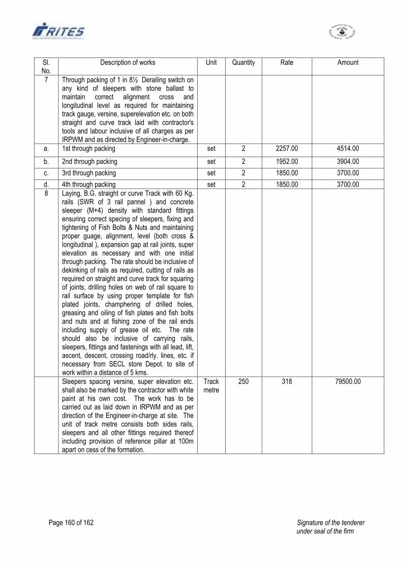
Page 160 of 162 Signature of the tenderer under seal of the firm
Sl. No.
Description of works Unit Quantity Rate Amount
7 Through packing of 1 in 8½ Derailing switch on any kind of sleepers with stone ballast to maintain correct alignment cross and longitudinal level as required for maintaining track gauge, versine, superelevation etc. on both straight and curve track laid with contractor's tools and labour inclusive of all charges as per IRPWM and as directed by Engineer-in-charge.
a. 1st through packing set 2 2257.00 4514.00
b. 2nd through packing set 2 1952.00 3904.00
c. 3rd through packing set 2 1850.00 3700.00
d. 4th through packing set 2 1850.00 3700.00
8 Laying, B.G. straight or curve Track with 60 Kg. rails (SWR of 3 rail pannel ) and concrete sleeper (M+4) density with standard fittings ensuring correct specing of sleepers, fixing and tightening of Fish Bolts & Nuts and maintaining proper guage, alignment, level (both cross & longitudinal ), expansion gap at rail joints, super elevation as necessary and with one initial through packing. The rate should be inclusive of dekinking of rails as required, cutting of rails as required on straight and curve track for squaring of joints, drilling holes on web of rail square to rail surface by using proper template for fish plated joints, champhering of drilled holes, greasing and oiling of fish plates and fish bolts and nuts and at fishing zone of the rail ends including supply of grease oil etc. The rate should also be inclusive of carrying rails, sleepers, fittings and fastenings with all lead, lift, ascent, descent, crossing road/rly. lines, etc. if necessary from SECL store Depot. to site of work within a distance of 5 kms.
Sleepers spacing versine, super elevation etc. shall also be marked by the contractor with white paint at his own cost. The work has to be carried out as laid down in IRPWM and as per direction of the Engineer-in-charge at site. The unit of track metre consists both sides rails, sleepers and all other fittings required thereof including provision of reference pillar at 100m apart on cess of the formation.
Track metre
250 318 79500.00
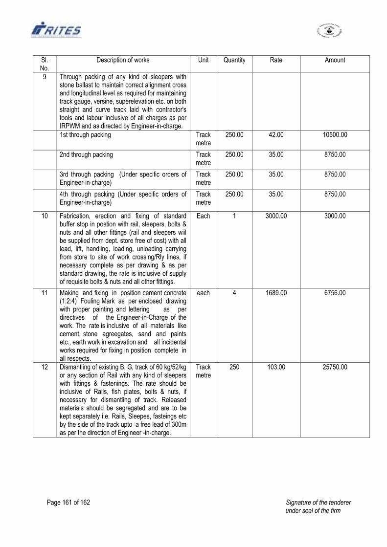
Page 161 of 162 Signature of the tenderer under seal of the firm
Sl. No.
Description of works Unit Quantity Rate Amount
9 Through packing of any kind of sleepers with stone ballast to maintain correct alignment cross and longitudinal level as required for maintaining track gauge, versine, superelevation etc. on both straight and curve track laid with contractor's tools and labour inclusive of all charges as per IRPWM and as directed by Engineer-in-charge.
1st through packing Track metre
250.00 42.00 10500.00
2nd through packing Track metre
250.00 35.00 8750.00
3rd through packing (Under specific orders of Engineer-in-charge)
Track metre
250.00 35.00 8750.00
4th through packing (Under specific orders of Engineer-in-charge)
Track metre
250.00 35.00 8750.00
10 Fabrication, erection and fixing of standard buffer stop in postion with rail, sleepers, bolts & nuts and all other fittings (rail and sleepers wiil be supplied from dept. store free of cost) with all lead, lift, handling, loading, unloading carrying from store to site of work crossing/Rly lines, if necessary complete as per drawing & as per standard drawing, the rate is inclusive of supply of requisite bolts & nuts and all other fittings.
Each 1 3000.00 3000.00
11 Making and fixing in position cement concrete (1:2:4) Fouling Mark as per enclosed drawing with proper painting and lettering as per directives of the Engineer-in-Charge of the work. The rate is inclusive of all materials like cement, stone agreegates, sand and paints etc., earth work in excavation and all incidental works required for fixing in position complete in all respects.
each 4 1689.00 6756.00
12 Dismantling of existing B, G, track of 60 kg/52/kg or any section of Rail with any kind of sleepers with fittings & fastenings. The rate should be inclusive of Rails, fish plates, bolts & nuts, if necessary for dismantling of track. Released materials should be segregated and are to be kept separately i.e. Rails, Sleepes, fasteings etc by the side of the track upto a free lead of 300m as per the direction of Engineer -in-charge.
Track metre
250 103.00 25750.00
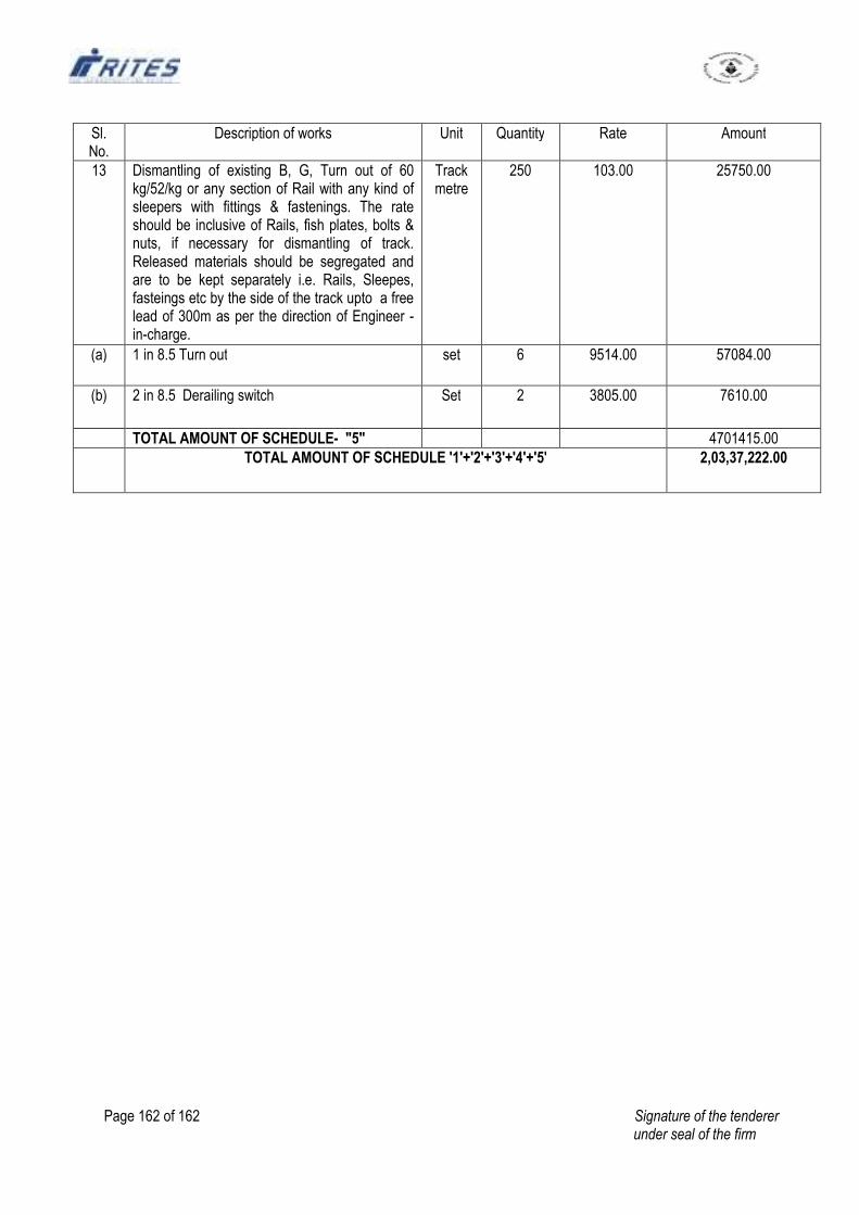
Page 162 of 162 Signature of the tenderer under seal of the firm
Sl. No.
Description of works Unit Quantity Rate Amount
13 Dismantling of existing B, G, Turn out of 60 kg/52/kg or any section of Rail with any kind of sleepers with fittings & fastenings. The rate should be inclusive of Rails, fish plates, bolts & nuts, if necessary for dismantling of track. Released materials should be segregated and are to be kept separately i.e. Rails, Sleepes, fasteings etc by the side of the track upto a free lead of 300m as per the direction of Engineer -in-charge.
Track metre
250 103.00 25750.00
(a) 1 in 8.5 Turn out set 6 9514.00 57084.00
(b) 2 in 8.5 Derailing switch Set 2 3805.00 7610.00
TOTAL AMOUNT OF SCHEDULE- "5" 4701415.00
TOTAL AMOUNT OF SCHEDULE '1'+'2'+'3'+'4'+'5' 2,03,37,222.00