Embed Size (px)
Citation preview

SPE ED & POS I T I ON
Sensors
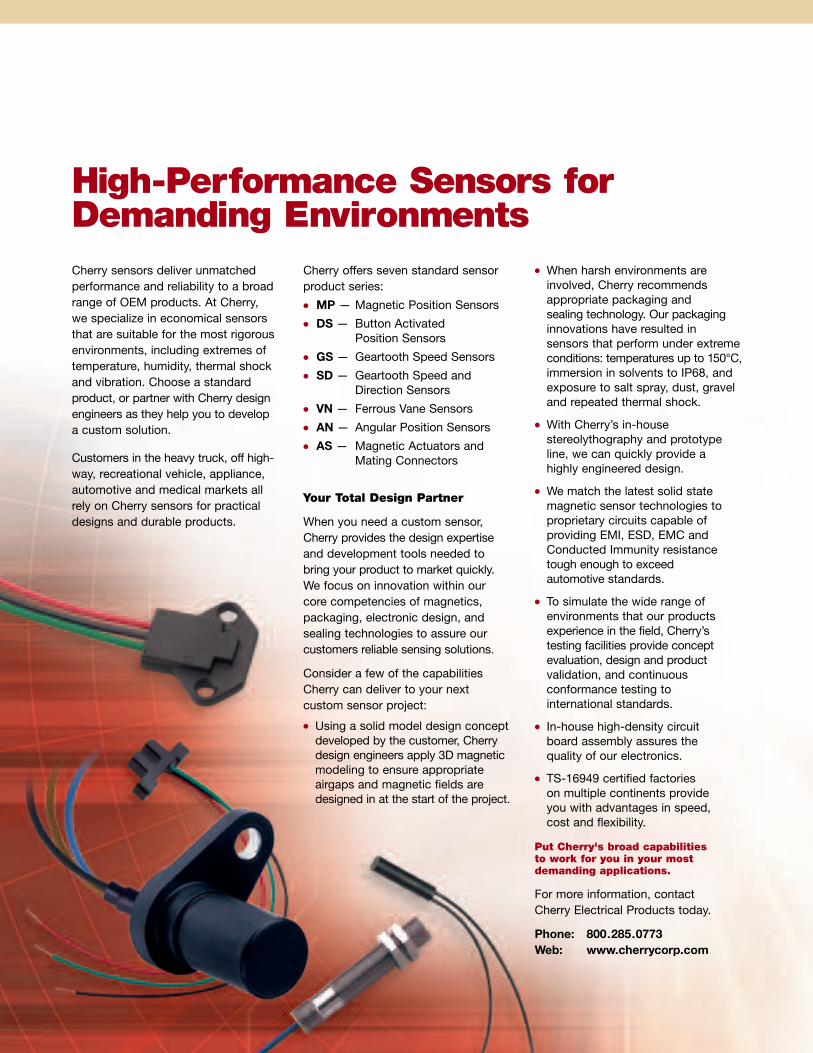
Cherry sensors deliver unmatchedperformance and reliability to a broadrange of OEM products. At Cherry,we specialize in economical sensorsthat are suitable for the most rigorousenvironments, including extremes oftemperature, humidity, thermal shockand vibration. Choose a standardproduct, or partner with Cherry designengineers as they help you to developa custom solution.
Customers in the heavy truck, off high-way, recreational vehicle, appliance,automotive and medical markets allrely on Cherry sensors for practicaldesigns and durable products.
Cherry offers seven standard sensorproduct series:
� MP — Magnetic Position Sensors
� DS — Button ActivatedPosition Sensors
� GS — Geartooth Speed Sensors
� SD — Geartooth Speed andDirection Sensors
� VN — Ferrous Vane Sensors
� AN — Angular Position Sensors
� AS — Magnetic Actuators andMating Connectors
Your Total Design Partner
When you need a custom sensor,Cherry provides the design expertiseand development tools needed tobring your product to market quickly.We focus on innovation within ourcore competencies of magnetics,packaging, electronic design, andsealing technologies to assure ourcustomers reliable sensing solutions.
Consider a few of the capabilitiesCherry can deliver to your nextcustom sensor project:
� Using a solid model design conceptdeveloped by the customer, Cherrydesign engineers apply 3D magneticmodeling to ensure appropriateairgaps and magnetic fields aredesigned in at the start of the project.
� When harsh environments areinvolved, Cherry recommendsappropriate packaging andsealing technology. Our packaginginnovations have resulted insensors that perform under extremeconditions: temperatures up to 150°C,immersion in solvents to IP68, andexposure to salt spray, dust, graveland repeated thermal shock.
� With Cherry’s in-housestereolythography and prototypeline, we can quickly provide ahighly engineered design.
� We match the latest solid statemagnetic sensor technologies toproprietary circuits capable ofproviding EMI, ESD, EMC andConducted Immunity resistancetough enough to exceedautomotive standards.
� To simulate the wide range ofenvironments that our productsexperience in the field, Cherry’stesting facilities provide conceptevaluation, design and productvalidation, and continuousconformance testing tointernational standards.
� In-house high-density circuitboard assembly assures thequality of our electronics.
� TS-16949 certified factorieson multiple continents provideyou with advantages in speed,cost and flexibility.
Put Cherry's broad capabilitiesto work for you in your mostdemanding applications.
For more information, contactCherry Electrical Products today.
Phone: 800.285.0773Web: www.cherrycorp.com
High-Performance Sensors forDemanding Environments

3
TABLE OF
ContentsMagnetic Position Sensors
MP Series
MP1014 Low-Profile 4
MP1001 Threaded Housing 5
MP1005 – 1007 Threaded Housing 6
MP1013 Snap-Fit 7
MP1021 Flange-Mount 8
MP2007 Threaded Housing 9
MP2017 Cylindrical Plastic Housing 10
MP2018 Mini Flange-Mount 11
MP2019 Flange-Mount 12
DS Series
DS Button Activated Position Sensors 13
Vane Sensors
VN Series
VN1015 Digital Vane Sensor 15
Geartooth Speed Sensors
GS Series
GS1001 – 1002 Threaded Housing 16
GS1005 – 1007 Threaded Housing 17
GS1012 Flange Mount 18
Geartooth Speed and Direction Sensors
SD Series
SD1002 – 1012 Speed and Direction 19
Angular Position Sensors
AN Series
AN1 Intrinsically Linear Angular Position Sensors 20
AN8 Thin Angular Position Sensors 21
Connection/Interface Details
Current Sink Interfacing 22
Actuator Magnets 22
Sensor Operation 23
Custom SensorsRugged Rotary Encoder 24
Magnetic Inertial Imbalance Sensor 24
Magnetic Speed and Direction Sensor 24

4
MAGNETIC SENSOR
MP1014 SeriesDigital Hall-effect position sensor in low-profileflange-mount housing.
Features� Capable of millions of operations
� Meets IEC529 IPX5 for water protection
� Reverse Battery Protection to -24VDC
� MP101401 south pole activatedunipolar switching
� MP101402 provides highly sensitiveunipolar switching
� MP101403 latches in presenceof south pole and unlatches inpresence of north pole magnet
� RoHS Compliant
Applications� Door position sensing
� Flow sensing
� Pedal switch
Open CollectorSinking Block Diagram
SpecificationsOutput
Operating Supply Saturation Output Operating Operate Point Release PointPart Voltage Range Current Voltage Current Temp Range Gauss GaussNumber (VDC) (mA max.) Output (mV max.) (mA max.) (°C) Function (max.) (min.)
MP101401 4.5 – 24 5.2 3-wire sink 400 20 -40 to 85 Unipolar Switch 185 (south) 60 (south)
MP101402 4.5 – 24 5.2 3-wire sink 400 20 -40 to 85 Unipolar Switch 95 (south) 20 (south)
MP101403 4.5 – 24 5.2 3-wire sink 400 20 -40 to 85 Bipolar Latch 120 (south) 100 (north)Notes: These sensors require the use of an external pull-up resistor, the value of which is dependent on the supply voltage. See page 22 for recommendations.Pull-up resistor should be connected between output (Green) and Vcc (Red).Unipolar switch output turns low in presence of magnetic south pole. Bipolar latch output latches high in presence of magnetic south poles and latches low in presence of magnetic north pole.
Magnet
1
3
4
VCC(red)
Pull-up ResistorOutput (green)Ground (black)
Dimensions inches (mm)All tolerances ±0.005 (0.13) unless otherwise noted.
0.250±.030(6.35±0.76)
4
3
1
ø0.115(ø2.92)
See Detail A
ApproximateSensingLocation
0.64
2(1
6.31
)
0.015(0.38)
2X 45° X0.020 (0.51)
0.85
5(2
1.72
)
0.120(3.05)0.228
(5.79) 0.680(17.27)
Active Surface
0.115(2.92)
2X R
0.130 (3.30)
0.075 (1.91) ApproximateLabel Location
0.324 (8.23)47.8
2X R 0.104(2.64)
0.105(2.67)
0.210(5.33) Detail A
Leads = 24 AWG PVC UL1569, pre-tinned.�All tolerances 0.007 (0.18) unless otherwise noted.
12±0.75(304.8±19.05)
Specifications subject to change without notice.

5
MAGNETIC SENSOR
MP1001 Series
Open CollectorSinking Block Diagram
SpecificationsOutput Operate Release
Operating Supply Saturation Output Operating Storage Point PointPart Voltage Range Current Voltage Current Temp Range Temp Range Gauss GaussNumber (VDC) (mA max.) Output (mV max.) (mA max.) (°C) (°C) (max.) (min.) Housing Cable Connector
MP100101 5 – 24 12 3-wire sink 700 25 -40 to 105 -40 to 105 300 60 SST — 12mmcircular
MP100102 5 – 24 12 3-wire sink 700 25 -40 to 125 -40 to 125 300 60 SST 22 AWG —x 1m BBB
Notes: These sensors require the use of an external pull-up resistor, the value of which is dependent on the supply voltage. See page 22 for recommendations.Pull-up resistor should be connected between output (Black) and Vcc (Brown).
Magnet
1
3
4
VCC(brown)Pull-up ResistorOutput (black)Ground(blue)
Dimensions inches (mm)All tolerances ±0.005 (0.13) unless otherwise noted.
M12-1
ActiveFace1.61 min. (41.0)
2.56 (65.0)
0.125 (REF)(3.18)
Part Label
Specifications subject to change without notice.
Solid state, magnetic position sensorswith electrical immunity protection.
Features� Stable output over operatingtemperature range
� Compatible with unregulated power supply
� Reverse battery protected to -24VDC
� Internal circuit protection to IEC529 1000— EMI resistant to 10V/m,30MHz to 1GHz
— ESD resistant to 4kV(contact discharge)
— Fast transient resistant to 2kV— Conducted immunity resistant to10VRMS@150kHz to 80MHz
— EMC compatible 30A/m@50Hz
� Meets IEC529 IP67 fordust and water protection
� South pole activated
� Open collector (sinking or NPN) outputcan be used with bipolar or cmos logiccircuits with suitable pull up resistor— Output switches low (off) when themagnetic field at the sensor exceedsthe operate point threshold
— Output switches high (on) when themagnetic field is reduced to belowthe release point threshold
� RoHS Compliant
Applications� Safety door
� Power sliding door
� Flow sensing

6
MAGNETIC SENSOR
MP1005–MP1007Series
SpecificationsOutput Operate Release
Operating Supply Saturation Output Operating Storage Point PointPart Voltage Range Current Voltage Current Temp Range Temp Range Gauss Gauss HousingNumber (VDC) (mA max.) Output (mV max.) (mA max.) (°C) (°C) (max.) (min.) Color Wires
MP100502 4.75 – 24 12 3-wire sink 700 25 -40 to 125 -40 to 125 300 60 Red 20 AWGx 1m BBB
MP100701 4.75 – 24 16 3-wire sink 700 25 -40 to 105 -40 to 125 300 60 Black 20 AWGx 1m BBB
Notes: These sensors require the use of an external pull-up resistor, the value of which is dependent on the supply voltage. See page 22 for recommendations.Pull-up resistor should be connected between output (Black) and Vcc (Brown).
Open CollectorSinking Block Diagram
Magnet
1
3
4
VCC (brown)Pull-up ResistorOutput (black)Ground (blue)
1.00(25.4)
15/32 - 32 TPI
MP100701
MP100502
M12-1
1.61 min. (41.0)2.56 (65.0)
Part Label
0.125 (REF)(3.18)
Dimensions inches (mm)All tolerances ±0.005 (0.13) unless otherwise noted.
Specifications subject to change without notice.
Features� Excellent output stability overoperating temperature range
� Regulated power supply not required
� Reverse battery protection to -24VDC
� Meets IEC529 IP67 fordust and water protection
� Wire: 20 AWG, tin plated,polyolefin insulation
� Anodized aluminum housing
� South pole activated
� RoHS Compliant
� Open Collector (NPN) output can beused with bipolar or cmos logic circuitswith suitable pull up resistor— Output switches low (off) when themagnetic field at the sensor exceedsthe operate point threshold
— Output switches high (on) when themagnetic field is reduced to belowthe release point threshold
Applications� Limit switch
� Home security
� Door position
Solid state, magnetic position sensorsin adjustable, threaded housing.

SpecificationsOutput Operate Release
Operating Supply Saturation Output Operating Storage Point Point ReversePart Voltage Range Current Voltage Current Temp Range Temp Range Gauss Gauss BatteryNumber (VDC) (mA max.) Output (mV max.) (mA max.) (°C) (°C) (max.) (min.) Leads Protection
MP101301 4.75 – 24 9 3-wire sink 400 25 -40 to 85 -40 to 105 300 60 24 AWG -24VDCx 150mm
MP101302 4.75 – 24 9 3-wire sink 400 25 -40 to 125 -40 to 125 300 60 24 AWG -24VDCx 150mm
MP101303 3.5 – 24 4 3-wire sink 500 25 -40 to 85 -40 to 105 45 -45 24 AWG None(latch) x 150mm
Notes: These sensors require the use of an external pull-up resistor, the value of which is dependent on the supply voltage. See page 22 for recommendations.Pull-up resistor should be connected between output (Green) and Vcc (Red).
7
MAGNETIC SENSOR
MP1013 Series
Sensor Pocket
0.430 (10.93)0.060(1.5)
0.138(3.5)
0.551 (14.0)
0.323(8.2)
0.178(4.51)
0.188 (4.78)
0.138 (3.5)
Open CollectorSinking Block Diagram
Magnet
1
3
4
VCC(red)
Pull-up ResistorOutput (green)Ground(black)
Dimensions inches (mm)All tolerances ±0.005 (0.13) unless otherwise noted.
0.056 (1.42) REF to Sensitive Point
5.91±0.25 (150.0±6.4)
0.125(3.18)
0.550(13.97)
0.416 REF(10.57)
0.175 (4.44) REF0.130 (3.30)
0.305(7.75)
Sensor Body is Glass-Filled NylonLeads 24 AWG
Specifications subject to change without notice.
Features� Solid state reliability
� Excellent output stability overoperating temperature range
� Regulated power supply not required
� Meets IEC529 IP67 for dust andwater protection
� Open Collector (NPN) output can beused with bipolar switch or cmos logiccircuits with suitable pull up resistor
� MP101301 and MP101302 —unipolar switch
— Output switches low (off) when themagnetic field at the sensor exceedsthe operate point threshold.
— Output switches high (on) whenthe magnetic field is reduced tobelow the release point threshold
� MP101303 — bipolar latch
— Output latches high (on) in thepresence of a south pole
— Output unlatches (low or off)in the presence of a north pole
� RoHS Compliant
Applications� Speed sensing� Door interlock sensing� Water flow sensing
Hall-effect position sensor with convenient snap-fit mounting.

8
MAGNETIC SENSOR
MP1021 SeriesFeatures� Three sensing orientations available in aconvenient flange mount housing
� Excellent output stability over operatingtemperature range
� Compatible with unregulated power supply
� Reverse battery protection to -24VDC
� Meets IEC529 IP67 for dust andwater protection
� Open Collector (NPN) output can beused with bipolar switch or cmos logiccircuits with suitable pull up resistor
� MP1012101–03 — north pole activatedunipolar switch
— Output switches low (off) when themagnetic field at the sensor exceedsthe operate point threshold.
— Output switches high (on) whenthe magnetic field is reduced tobelow the release point threshold
� MP102104– 06 — bipolar latch
— Output latches high (on) in thepresence of a north pole
— Output unlatches (low or off)in the presence of a south pole
� RoHS Compliant
Applications� Interrupt switch� Limit switch� Door position
Digital Hall-effect position sensor in plastic flange-mount housing
Open CollectorSinking Block Diagram
Magnet
1
3
4
VCC(red)
Pull-up ResistorOutput (green)Ground (black)
Dimensions inches (mm)All tolerances ±0.005 (0.13) unless otherwise noted.
0.375(9.53)
0.375(9.53)
0.563 REF(14.3)
1.125(28.58)
6.00 (152.4) Min.
0.200 REF(5.08)Sensing Location A
Sensing Location B
Sensing Location C
2x Slot 0.308 (7.82) x 0.125 (3.18)
0.625 (15.88)
0.250(6.35)0.750
(19.05)
0.125(3.18)
0.562 (14.27)
0.563 REF(14.3)
0.563 REF(14.3)
Capsule: 30% Glass-Filled Polyester.Leads: 24 AWG PVC UL 1569, Pre-Tinned.
Specifications subject to change without notice.
SpecificationsOutput Operate Release
Operating Supply Saturation Output Operating Point PointPart Voltage Range Current Voltage Current Temp Range Gauss Gauss SensingNumber (VDC) (mA max.) Output (mV max.) (mA max.) (°C) Function (max.) (min.) Location
MP102101 4.5 – 24 12 3-wire sink 500 25 -40 to 85 Switch 400 (north) 195 (north) A
MP102102 4.5 – 24 12 3-wire sink 500 25 -40 to 85 Switch 400 (north) 195 (north) B
MP102103 4.5 – 24 12 3-wire sink 500 25 -40 to 85 Switch 400 (north) 195 (north) C
MP102104 4.5 – 24 12 3-wire sink 500 25 -40 to 85 Latch 60 (north) 60 (south) A
MP102105 4.5 – 24 12 3-wire sink 500 25 -40 to 85 Latch 60 (north) 60 (south) B
MP102106 4.5 – 24 12 3-wire sink 500 25 -40 to 85 Latch 60 (north) 60 (south) CNotes: These sensors require the use of an external pull-up resistor, the value of which is dependent on the supply voltage. See page 22 for recommendations.Pull-up resistor should be connected between output (Green) and Vcc (Red).

9
MAGNETIC SENSOR
MP2007 SeriesReed-based magnetic position sensorin aluminum threaded housing.
Features� Zero power consumption
� Suitable for DC and AC circuits
� Contacts hermetically sealed for long life
� RoHS Compliant
Specifications
Power Switching Breakdown Switching Contact Operating OperatePart Contact Rating Voltage Voltage Current Resistance Temp Range TimeNumber Form (W max.) (AC/DC max.) (VDC min.) (Amps max.) (Ohms max.) (°C) (msec typical)
MP200701 SPST-NO 10 AC 100 200 0.5 0.100 -40 to 105 0.3Form A DC 100
MP200702 SPST-NC 3 AC 30 200 0.2 0.100 -40 to 105 1.0Form B DC 30
MP200703 SPDT-CO 3 AC 30 200 0.2 0.100 -40 to 105 1.0Form C DC 30
Dimensions inches (mm)All tolerances ±0.005 (0.13) unless otherwise noted.
1.00(25.4)
15/32 - 32 TPI
0.200 REF(5.08)
12.00±0.300(304.8±7.62)
Barrel: Black Anodized Aluminum.24 AWG PVC UL 1569 Leads, Pre-Tinned.
Form C is a Three-Wire Device: Black = N/O; Blue = N/C; Brown = Common
Operate Distance with �AS101001 Magnetic Actuator
Operate Distance: 0.150 (3.81) Min.Release Distance: 0.500 (12.7) Max.
Specifications subject to change without notice.

10
MAGNETIC SENSOR IN CYLINDRICAL PLASTIC HOUSING
MP2017 Series
Features� Hermetically sealed contacts for long life
� Zero power consumption
� Available in a variety of standardcontact configurations
� Resistant to moisture and dirt
� A standard magnetic actuator isavailable in the same housing(Cherry part number AS201701)
� RoHS Compliant
Reed-based magnetic sensor encapsulatedin smooth plastic barrel.
Specifications
Power Switching Breakdown Switching Contact Operating OperatePart Contact Rating Voltage Voltage Current Resistance Temp Range TimeNumber Form (W max.) (AC/DC max.) (VDC min.) (Amps max.) (Ohms max.) (°C) (msec typical)
MP201701 SPST-NO 10 AC 100 200 0.5 0.100 -40 to 105 0.3Form A DC 100
MP201702 SPST-NC 3 AC 30 200 0.2 0.100 -40 to 105 1.0Form B DC 30
MP201703 SPDT-CO 3 AC 30 200 0.2 0.100 -40 to 105 1.0Form C DC 30
Dimensions inches (mm)All tolerances ±0.005 (0.13) unless otherwise noted.
1.00(25.4)
ø0.243(6.16)
0.200 REF(5.08mm)
12.00±0.300(304.8±7.62)
Capsule: 30% Glass-Filled Polyester.�Leads: 24 AWG PVC UL 1569, Pre-Tinned.
Form C is a Three-Wire Device: Black = N/O; Blue = N/C; Brown = Common
Operate Distance: 0.150 (3.81) Min.Release Distance: 0.500 (12.7) Max.
Operate Distance with AS201701 Magnetic Actuator
MP2017AS201701
Specifications subject to change without notice.

Features� Contacts hermetically sealed for long life
� Zero power consumption
� Resistant to moisture and dirt
� A standard magnetic actuator isavailable in the same housing(Cherry part number AS201801)
� RoHS Compliant
11
Specifications
Power Switching Breakdown Switching Contact Operating OperatePart Contact Rating Voltage Voltage Current Resistance Temp Range TimeNumber Form (W max.) (AC/DC max.) (VDC min.) (Amps max.) (Ohms max.) (°C) (msec typical)
MP201801 SPST-NO 10 AC 100 200 0.5 0.100 -40 to 105 0.3Form A DC 100
MP201802 SPST-NC 3 AC 30 200 0.2 0.100 -40 to 105 1.0Form B DC 30
Dimensions inches (mm)All tolerances ±0.005 (0.13) unless otherwise noted.
0.906(23.01)
Slot — 2 Places0.128 (3.25) x 0.160 (4.06)
0.295(7.49)
0.433(11.0)
0.177(4.5)
0.236(5.99)
0.118(3.0)
0.550(13.97)
0.550(13.97)
0.200 REF(5.08)
12.00±0.300(304.80±7.62)
Capsule: 30% Glass-Filled Polyester.�Leads: 24 AWG PVC UL 1569, Pre-Tinned.
Operate Distance with AS201801 Magnetic Actuator
Operate Distance: 0.250 (6.35) Min.Release Distance: 0.700 (17.8) Max.
MAGNETIC SENSOR
MP2018 SeriesReed-based magnetic position sensorin plastic flange-mount package.
Specifications subject to change without notice.

12
MAGNETIC SENSOR
MP2019 SeriesReed-based magnetic position sensorin plastic flange-mount package.
Features� Immune to hostile environments
� Contacts hermetically sealed for long life
� Suitable for DC and AC circuits
� Zero power consumption
� A standard magnetic actuator isavailable in the same housing(Cherry part number AS201901)
� RoHS Compliant
Specifications subject to change without notice.
Specifications
Power Switching Breakdown Switching Contact Operating OperatePart Contact Rating Voltage Voltage Current Resistance Temp Range TimeNumber Form (W max.) (AC/DC max.) (VDC min.) (Amps max.) (Ohms max.) (°C) (msec typical)
MP201901 SPST-NO 10 AC 100 200 0.5 0.100 -40 to 105 0.3Form A DC 100
MP201902 SPST-NC 3 AC 30 200 0.2 0.100 -40 to 105 1.0Form B DC 30
MP201903 SPDT-CO 3 AC 30 200 0.2 0.100 -40 to 105 1.0Form C DC 30
Dimensions inches (mm)All tolerances ±0.005 (0.13) unless otherwise noted.
Slot — 2 Places:0.128 (3.25) x 0.310 (7.87)
0.625(15.88)
1.125 (28.58)
0.562(14.27)
0.200(5.08)
12.00 ± 0.300(304.8 ± 7.62)
Capsule: 30% Glass-Filled Polyester.�Leads: 24 AWG PVC UL 1569, Pre-Tinned.
0.375(9.53)
0.250(6.35)
0.135(3.43)
0.750(19.1)
Operate Distance with AS201901 Magnetic Actuator
Operate Distance: 0.400 (10.16) Min.Release Distance: 0.900 (22.86) Max.

13
BUTTON ACTIVATED POSITION SENSOR
DS SeriesSolid State Sensor
Features
� Fits mounting dimensions of popularsnap-action switches
� Tested to more than 10 milliion operations
� High ratio and standard ratioactuator position
� Available with lever, roller, andsimulated roller actuators
� Solid state sinking output usingHalf effect technology
� UL recognized
� RoHS compliant
Applications
� Pedal position sensing
� Door/lid interlock
� Joystick position sensing
� End-of-Travel sensing
Material Specifications
� Case, cover, actuating button:Thermoplastic Polyester (PBT)UL 94 V-0
Specifications subject to change without notice.
0.406(10.3)
0.157(4.0)
0.516(13.1)
0.134 ± 0.004(3.4 ± .1)0.110
(2.8) 1.134(28.8)
0.807(20.37)
0.874(22.2)
1.094(27.8)
0.110(2.8)
VCC
Output
Ground
0.126 ± 0.004 ( 3.2 ± .1)
0.406(10.3)
0.638(16.2) MAX
0.579 ± 0.024(14.7 ± .6) OP
Dimensions inches (mm)All tolerances ±0.005 (0.13) unless otherwise noted.
SpecificationsSupply Output Sensor State
Part Supply Current Output Current Button Operating StorageNumber Voltage (VDC) (mA max.@25ºC) Type (mA max.) (button at rest position) Temp Range Temp Range
DS Series 4.5 to 24 15 Sink 20 Normally Off -40º to 85ºC -40º to 150ºC
Notes: These sensors require the use of an external pull-up resistor, the value of which is dependent on the supply voltage. See page 22 for recommendations.Pull-up resistor should be connected between output and Vcc.
Accepts AMP Connector102241-1 or equivalent

14 Specifications subject to change without notice.
Lever Operate MaxActuation Lever Max Operate Point Min Movement MaxLength Activation Pretravel Point Tolerence Overtravel Differential Operating
Part Number Lever Style (inch / mm) Ratio (inch / mm) (inch / mm) (+/-inch, +/-mm) (inch / mm) (inch / mm) Force (g)
DS1101AA n/a n/a n/a 0.06 0.58 0.02 0.04 0.01
1.5 14.7 0.6 1.0 0.2 84
DS1101JA SS Leaf 0.87 Std 0.08 0.60 0.03 0.04 0.0122.0 2.1 15.2 0.7 1.0 0.2 84
DS1101KA SS Leaf 1.04 High 0.14 0.60 0.05 0.07 0.0226.5 3.5 15.2 1.2 1.7 0.5 53
DS1101JD SS Leaf 1.40 Std 0.17 0.60 0.06 0.08 0.0235.7 4.3 15.2 1.4 2.1 0.5 43
DS1101KD SS Leaf 1.58 High 0.28 0.60 0.09 0.14 0.0340.2 7.1 15.2 2.4 3.6 0.8 26
DS1101JJ SS Leaf 2.34 Std 0.32 0.60 0.11 0.16 0.0459.4 8.1 15.2 2.7 4.0 0.9 23
DS1101KJ SS Leaf 2.52 High 0.53 0.60 0.18 0.27 0.0663.9 13.5 15.2 4.5 6.7 1.5 14
DS1101RA Roller 0.81 Std 0.07 0.81 0.02 0.04 0.0120.5 1.8 20.6 0.6 0.9 0.2 99
DS1101TA Roller 1.0 High 0.12 0.81 0.04 0.06 0.0125.0 3.1 20.6 1.0 1.5 0.3 59
DS1101SC Simulated Roller 1.29 Std 0.15 0.73 0.05 0.07 0.0232.7 3.8 18.5 1.3 1.9 0.4 48
DS1101UC Simulated Roller 1.47 High 0.25 0.73 0.08 0.12 0.0337.2 6.3 18.5 2.1 3.1 0.7 29
BUTTON ACTIVATED POSITION SENSOR
DS Series (continued)
Specifications
Actuation Length StandardRatio
High Ratio
0.177 (4.50) 0.355 (9.0)
Roller

Features� Available in two operatingtemperature ranges
� Immune to moisture and dust
� Reliable and repeatable
� No mechanical contacts to wear out
� Operates from 4.5 to 24VDC
� Reverse battery protection to -24VDC
� RoHS Compliant
� Open collector (sinking or NPN) outputcan be used with bipolar or cmos logiccircuits with suitable pull up resistor
� Sensor body material:glass-filled polyester
� Recommended vane parameters: lowcarbon material at least 0.040″ thick,should penetrate to a depth <0.120″from bottom of sensor slot.
� 25 khz maximum operating speed
15
DIGITAL VANE SENSOR
VN1015 SeriesMagnetically activated digital vane sensor in a rugged, overmoldedplastic housing with three pins or 3-wire flying leads.
Open CollectorSinking Block Diagram
SpecificationsOutput
Operating Supply Saturation Output Operating StoragePart Voltage Range Current Voltage Current Temp Range Temp RangeNumber (VDC) (mA max.) Output (mV max.) (mA max.) (°C) (°C) Termination
VN101501 4.5 – 24 6 3-pin sink 400 25 -40 to 85 -40 to 85 pins
VN101502 5.0 – 24 6 3-pin sink 400 25 -40 to 125 -40 to 125 pins
VN101503 4.5 – 24 6 3-wire sink 400 25 -40 to 85 -40 to 85 24 AWG x150mm leads
VN101504 5.0 – 24 6 3-wire sink 400 25 -40 to 125 -40 to 125 24 AWG x150mm leads
Notes: These sensors require the use of an external pull-up resistor, the value of which is dependent on the supply voltage. See page 22 for recommendations.Pull-up resistor should be connected between output (Green) and Vcc (Red).
Permanent Magnet
1
3
2
VCC (red)
Pull-up Resistor
Output (green)Ground (black)
FerrousVane Regulator
Dimensions inches (mm)All tolerances ±0.005 (0.13) unless otherwise noted.
0.750(19.05)
0.139(3.53)
0.975(24.77)
0.475(12.07)
0.500(12.70)
0.135(3.43)
0.425(10.80)
0.124(3.15)
0.37 REF.(9.4) 0.080
(2.03)5.9
(150.0)
0.050 Typ.(1.27)
0.250(6.35)
ø 0.129(3.28)
2
Wire Insulation: Polyolefin
3
123 1
Specifications subject to change without notice.
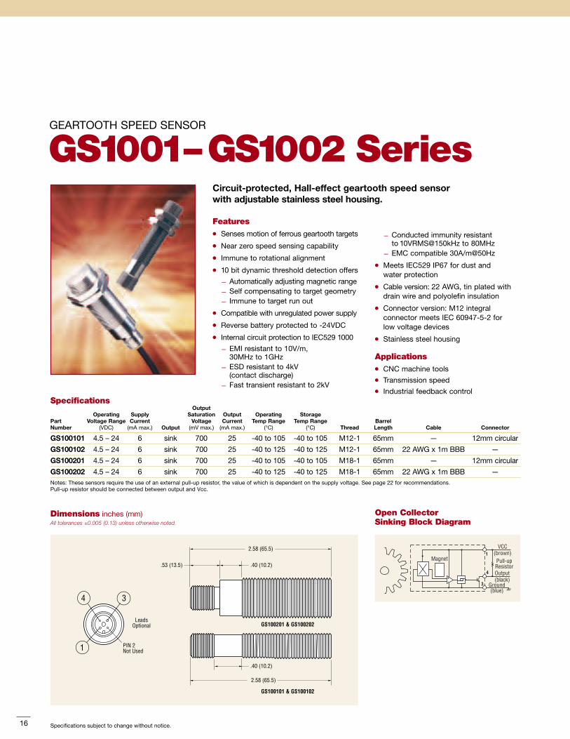
GEARTOOTH SPEED SENSOR
GS1001–GS1002 SeriesCircuit-protected, Hall-effect geartooth speed sensorwith adjustable stainless steel housing.
SpecificationsOutput
Operating Supply Saturation Output Operating StoragePart Voltage Range Current Voltage Current Temp Range Temp Range BarrelNumber (VDC) (mA max.) Output (mV max.) (mA max.) (°C) (°C) Thread Length Cable Connector
GS100101 4.5 – 24 6 sink 700 25 -40 to 105 -40 to 105 M12-1 65mm — 12mm circular
GS100102 4.5 – 24 6 sink 700 25 -40 to 125 -40 to 125 M12-1 65mm 22 AWG x 1m BBB —
GS100201 4.5 – 24 6 sink 700 25 -40 to 105 -40 to 105 M18-1 65mm — 12mm circular
GS100202 4.5 – 24 6 sink 700 25 -40 to 125 -40 to 125 M18-1 65mm 22 AWG x 1m BBB —Notes: These sensors require the use of an external pull-up resistor, the value of which is dependent on the supply voltage. See page 22 for recommendations.Pull-up resistor should be connected between output and Vcc.
Open CollectorSinking Block Diagram
Magnet1
3
4
VCC(brown)Pull-up ResistorOutput (black)
Ground (blue)
Dimensions inches (mm)All tolerances ±0.005 (0.13) unless otherwise noted.
34
1 PIN 2Not Used
LeadsOptional
2.58 (65.5)
GS100201 & GS100202
GS100101 & GS100102
.40 (10.2).53 (13.5)
2.58 (65.5)
.40 (10.2)
16 Specifications subject to change without notice.
Features� Senses motion of ferrous geartooth targets
� Near zero speed sensing capability
� Immune to rotational alignment
� 10 bit dynamic threshold detection offers
— Automatically adjusting magnetic range— Self compensating to target geometry— Immune to target run out
� Compatible with unregulated power supply
� Reverse battery protected to -24VDC
� Internal circuit protection to IEC529 1000
— EMI resistant to 10V/m,30MHz to 1GHz
— ESD resistant to 4kV(contact discharge)
— Fast transient resistant to 2kV
— Conducted immunity resistantto 10VRMS@150kHz to 80MHz
— EMC compatible 30A/m@50Hz
� Meets IEC529 IP67 for dust andwater protection
� Cable version: 22 AWG, tin plated withdrain wire and polyolefin insulation
� Connector version: M12 integralconnector meets IEC 60947-5-2 forlow voltage devices
� Stainless steel housing
Applications� CNC machine tools� Transmission speed� Industrial feedback control

17Specifications subject to change without notice.
GEARTOOTH SPEED SENSOR
GS1005–GS1007 SeriesHall-effect geartooth speed sensor with adjustable aluminum housing.
Features� Senses motion of ferrous geartooth targets
� Near zero speed sensing capability
� Immune to rotational alignment
� 10 bit dynamic threshold detection offers
— Automatically adjusting magnetic range— Self compensating to target geometry— Immune to target run out
� Compatible with unregulated power supply
� Reverse battery protected to -24VDC
� Meets IEC529 IP67 for dustand water protection
� Discrete wire version: 20 AWG,tin plated, polyolefin insulation
� Connector version: M12 integralconnector meets IEC 60947-5-2for low voltage devices
� Hard coat anodized aluminum housing
Applications� Exercise equipment
� Food processing equipment
� Speedometer
SpecificationsOutput
Operating Supply Saturation Output Operating StoragePart Voltage Range Current Voltage Current Temp Range Temp Range BarrelNumber (VDC) (mA max.) Output (mV max.) (mA max.) (°C) (°C) Thread Length Leads Connector
GS100501 4.5 – 24 6 sink 400 25 -40 to 105 -40 to 105 M12-1 65mm — 12mmcircular
GS100502 4.5 – 24 6 sink 400 25 -40 to 125 -40 to 125 M12-1 65mm 20 AWG x 1m BBB —GS100701 4.5 – 24 6 sink 400 25 -40 to 125 -40 to 125 15/32″ – 32 1.00″ 20 AWG x 1m BBB —Notes: These sensors require the use of an external pull-up resistor, the value of which is dependent on the supply voltage. See page 22 for recommendations.Pull-up resistor should be connected between output (Black) and Vcc (Brown).
Open CollectorSinking Block Diagram
Magnet1
3
4
VCC (brown)Pull-up ResistorOutput (black)
Ground (blue)
Dimensions inches (mm)All tolerances ±0.005 (0.13) unless otherwise noted.
34
12.58 (65.5)
.40 (10.2)
LeadsOptional
GS100701
GS100501 & GS100502
0.125 REF(3.18)
15/32 - 32 TPI
PIN 2Not Used

LASER MARK LOCATION
90°
Ø 0.61 (15.6)
Ø 0.26 (6.5)
Ø 0.91 (23)
Ø 0.75 (18.9)
Ø 0.64 (16.2)
0.84 (21.3)
1.11(28.2)
1.43(36.3)
0.67(17)
2.38(60.5)
0.10(2.5)
0.10(2.5)
OUTPUT
GROUND
VCC
0.25(6.3)
0.49(12.5)
0.14(3.5)
1.24 ±0.01(31.55 ±0.2)
MEXICOXXXXXXXX
GEARTOOTH SPEED SENSOR
GS1012 SeriesFlange mount gear sensor rated to 150°C.
Features� Capable of operating up to 150ºC
� Sealed design exceeds IEC60529IP67 standard for immersion
� Resistant to fuels, solvents, andlubricants associated with engines,transmissions, brakes and chassissystems
� Easily customizable connectororientation
� ESD resistant to 15kV(contact discharge)
� Operates at arbitrarily low speeds
� Mating connector Delphi 12162280
Applications� Transmission speed� Wheel speed� Engine speed� Anti-lock braking systems
Open CollectorSinking Block Diagram
SpecificationsOutput
Operating Supply Saturation Output Operating StoragePart Voltage Range Current Voltage Current Temp Range Temp RangeNumber (VDC) (mA max.) Output (mV max.) (mA max.) (°C) (°C) Leads Connector
GS101205 5.0 – 30 6 sink 600 25 -40 to 150* -55 to 150 — Delphi**
Notes: These sensors require the use of an external pull-up resistor, the value of which is dependent on the supply voltage. See page 22 for recommendations.Pull-up resistor should be connected between output and Vcc.
*For continuous operation at 150°C, supply voltage should be limited to 5.5V max.**Delphi 12162280
MagnetA
C
B
VCC(brown)Pull-upResistorOutput(black)
Ground(blue)
Dimensions inches (mm)
18 Specifications subject to change without notice.

19Specifications subject to change without notice.
GEARTOOTH SPEED AND DIRECTION SENSOR
SD1002–SD1012 SeriesHall-effect geartooth speed and direction sensor with adjustablealuminum or flange-mount plastic housing.
Features� Sense speed and direction of ferrousgeartooth targets
� Plastic flange mount sensor rated to 125°C� Near zero speed sensing capability� Capable of 8000+Hz target speed� Locating mark provided to assure correctrotational alignment
� 10 bit dynamic threshold detection offers:— Automatically adjusting magnetic range— Self compensating to target geometry— Immune to target run out
� Compatible with unregulated power supply� Reverse battery protected to -30VDC� Internal circuit protection to IEC529 1000— EMI resistant to 10V/m, 30MHz to 1GHz— ESD resistant to 4kV(Contact discharge)
— Fast transient resistant to 2kV— Conducted immunity resistant to10VRMS@150kHz to 80MHz
— EMC compatible 30A/m @ 50 Hz� Meets IEC60529 IP67 for dust andwater protection— Integral Connector version: 4-pinDelphi Metri Pack 150.2 No. 12162833.Mates with Terminal No. 12124075.
— Discrete wire version: 20 AWG,PVC insulation, UL1007/1569
Application� Wheel speed and direction� Transmission speed and direction� Hoist speed and direction
Open CollectorSinking Block Diagram
SpecificationsOutput
Operating Supply Saturation Output Operating StoragePart Voltage Range Current Voltage Current Temp Range Temp Range HousingNumber (VDC) (mA max.) Output (mV max.) (mA max.) (°C) (°C) Material
SD100203 4.75 – 24 20 sink 1000 20 -40 to 85 -40 to 85 Aluminum
SD101201 4.75 – 24 20 sink 1000 20 -40 to 125 -40 to 125 PlasticNotes: SD101201 uses Delphi Metri-Pack 150.2 Series Part No. 12162833. Mating terminal: Delphi Part No. 12124075.A pull up resistor is required between power and each output. Resistor value is dependent upon input voltage. See page 22 for recommendations.
Magnet
C
D
B
A
VCC (brown)
Pull-upResistor
(black)
Ground(blue)
Speed
DirectionV Reg
Regulator
(white)
Dimensions inches (mm)All tolerances ±0.005 (0.13) unless otherwise noted.
2.05 (52.07) 12.00 ± 0.250 (304.8 ± 6.35)
0.200 ± 0.030 (5.08 ± 0.76)
LocatingMark
Aprox. Label LocationM18 x 1 Threads
0.181 (4.6)
1.92 ± 0.009(48.79 ± 0.25)
0.25 (6.35)
3.0 (76.2) 0.976(24.8)
0.511(13.0)
ø 0.703 ± 0.005(17.86 ± 0.13)
Pin D (Ground)
Pin C (Power)
R 0.010 (7.25)
Pin A (Direction Output)
Pin B (Speed Output)
R 0.468 (11.88)
R 0.128 (3.25)
SD100203
SD101201

20 Specifications subject to change without notice.
ANGULAR POSITION SENSOR
AN1Series
Features
� Patented non-contact angularposition sensor
� Magnet/sensor orientation providesintrinsically linear output up to100 degrees of electrical rotation(120 degrees mechanical rotation)without need for electrical compensation
� Provided with programmed output orend-user re-programmable to eliminatemechanical and process tolerances inyour final assembly
� Adjustable rising or falling output slopewith programmable offset, gain temperaturecompensation, and clamping voltage
� Return spring provides resistance toCCW motion
� Provided with EMI/ESD protection
� Fully encapsulated electronIcs toIEC 60529 IP67
� ILAPS® technology can be custom pack-aged to meet your exact requirements(minimum quantities apply)
Applications
� Throttle and valve position sensing
� User interface controls(vehicles, gaming)
� Pedal position sensing
� Implement position sensing
� Gear Selection
� Joystick position
Dimensions inches (mm) Electrical Specifications
Effective Rotational Maximum 100ºSensing Range electrical outputInput Voltage 5.0 V ± 10%Input Current 10mA, max. @ 5VDCInput Current, Output(s) 25mA, max. per outputShorted to GroundMax Overvoltage 24VDCSensor Output @ 5VDC 0.5V to 4.5V Max,(Ratiometric to programmable withinInput Voltage) 5% to 95% of the nominal
voltage with positive ornegative slopes
Output Linearity @ 5VDC ± 2%Resolution AnalogResponse Time .23mSECBulk Current Injection SAE J1113-4, 250kHz to
500MHz., 60mA/mConduction and Coupling SAE J1113-12; ± 200VElectronic Discharge SAE J1113-13; ± 15kVRadiated Immunity SAE J1113-21; 10kHz to
18GHz, 100V/mImmunity to SAE J1113-22; 600uTMagnetic Fields AC Field, 5Hz to 2kHz,
.2mT & 1mT DC FieldImmunity to AC Fields SAE J1113-25, 15,000V/mRadiated Emmissions SAE J1113-41; Class 4
Environmental Specifications
Vibration 10 G's peak, 20 Hzto 1000 Hz
Shock 20 G's, half sine pulse,13 ms duration
Operating Temperature -40°C to +125°CStorage Temperature -55°C to +135°C
Intrinsically Linear Angular Position Sensor
Mechanical Specifications
Mechanical Travel 120º CCW maximumrotational travel
Rotation Torque 0.12N-m max with return springMass 12 gramsLife +10 million full cyclesDither (2º Travel) +80 million cyclesMating Connection Connector: Packard metri-pack
150 12162185Terminal: 12124075
AN101101 120° Sensor Output(Typically Based on 5V Supply)
5V4.5V
4V
3V
2V
1V0.5V
0°5°
40° 80°85°
120°
Outp
utVo
ltage
Rotational Angle

21
THIN ANGULAR POSITION SENSOR
AN8 Series
Specifications subject to change without notice.
* Includes AN8 sensor and AS500106 magnetic actuator
Features and Benefits
� Angular position with high tolerancefor misalignment
� Provides non-contact angular positionsensing and full 360° rotation
� 5VDC ratiometric device.
� Linear output over specific angularrotation ranges available on request
� Sealed design exceeds IEC 60529 IP67standard for immersion
� Performs with AS500106 standardmagnetic carrier
� Sensor can be programmed for usewith custom magnets
� Custom programming option for risingor falling output slope with selectableoffset, gain, clamp voltage
� PWM output option available forcustom applications
� Provided with EMI/ESD protectionto SAE J1113 standards
� Maximum operating temperatureof 150°C (optional)
� No mechanical interface meansno parts to wear out
Description
The sensor is applied by rotating a magneticactuator close to the face of the sensor.Output voltage varies with angular positionof the magnet relative to the sensor.
Optimal performance is achieved withCherry’s AS500106 magnetic actuator.Sensor kits including this standardmagnet are available
Applications
� Throttle position sensor
� Replacement for smart bearings
� PRNDL switch for harsh environments
� Steer wheel position for driveby wire systems
� Pedal position sensor
Mechanical Specifications
Mechanical Travel 0 to 360 degrees(no stops)
Dither No mechanical contactMating Connector Connector: Delphi
Metri-pak150.2 12162185Terminal:12124075
Maximum Air Gap 5mmMaximum Center-to- 2mm (magnet to sensor)Center Offset
Electrical Specifications
Effective rotational 0 to 360 degreessensing range of rotationInput Voltage 5.0 VDC ± 10%Max Overvoltage 20 VDC reversed
voltage -10 VDCOutput Current Range 8mAResolution AnalogConduction and Coupling SAE J1113-12; ± 200VElectronic Discharge SAE J1113-13; ± 15kVImmunity to Magnetic Fields SAE J1113-21Conducted Transient SAE J1113-42EmmissionsRadiated Emmissions SAE J1113-41; Class 4Output Linearity ± 2.5% Full Scale(with supplied magnet)Analog Output Slew Rate 200 V.msAccuracy ± 2%Operating Temperature -40 to 125°c
(150°C max option)
Dimensions inches (mm)48.3
41.9
57.33
22
R 15.572X Ø 5.3 ± 0.1
Std.Magnet
Rotation
5.0MAX AIR GAP
N. S.
35.5 ± 0.1
48.3
41.9
57.33
22
R 15.572X Ø 5.3 ± 0.1
Std.Magnet
Rotation
N. S.
35.5 ± 0.1
17.7
GNDV+8.5 ± 0.1 OUTPUT
Programmable, non-contact magnetic position sensorscapable of continuous rotation
Sensor Output Signal
Output Voltage(Vs = 5 VDC. Outputis ratiometric for Vs= 4.5 to 5.5 VDC.)
Rotation Angle(Percent of Sensing Range: 45º; 90º; 180º; or 360º)
45°, 90° and 180° Versions
Sensor
AN820001
AN820002
AN820003
AN820004
SensingRange
180º
360º
45º
90º
Sensor/MagnetAssembly Kit #
CU103601*
CU103602*
CU103603*
CU103605*
Note: See page 22 for dimensions on the AS500106 Mating Magnet Carrier.

22 Specifications subject to change without notice.
MAGNETS AND
InterfacingACTUATOR MAGNET
AS101001
MAGNET CARRIER
AS500106
Easy to install actuator magnetwith threaded aluminum holder.
� South pole facing Alnico magnet
Also available in the same package:
� AS101002 with north pole facingAlnico magnet
� AS101003 with south pole facingsamarium cobalt magnet
� PPS Housing
� SmCo28 Magnet
� Recommended fastenener: M4 Cap Screw
� Recommended torque: 3Nm (26.5 in lbs.)
Dimensions inches (mm)All tolerances ±0.005 (0.13) unless otherwise noted.
Magnet
Aluminum Holder #8 - 32 THREAD
ø 0.250(6.35)
ø 0.31(7.87)
0.032(0.81)
0.050(1.27)
0.68(17.27)
0.38(9.65)
2 x 0.155(2 x 8)
ø3 x 9
ø7.4
ø12
ø23.070.197(5.0)
29
15
Sensor Connector Connection GridSeries Type Vcc Output Ground Direction Speed
MP 12mm circular 1 4 3 N/A N/AWire Lead Brown Black Blue N/A N/AWire Lead Red Green Black N/A N/A
GS 12mm circular 1 4 3 N/A N/AWire Lead Brown Black Blue N/A N/ADelphi A B C N/A N/A
VN Pin 1 3 2 N/A N/AWire Lead Red Green Black N/A N/A
SD Wire Lead Brown — Blue White BlackDelphi C — D A B
Current Sink Interfacing
3-Wire Sinking Interface
Sinking outputs are often used in negative logic applications, where a low signal is requiredfor an active state. There, sinking outputs normally have current flowing into the device outputlead when the device is active. Also called “open collector outputs,” sinking outputs arecompatible with any logic family since a wide voltage range may be used for Vcc. Furthermore,the voltage level used to power the Hall effect assembly may differ from the pull-up resistorto which it is attached. The external pull-up resister connected between the output and Vccis required for proper operation. With the resistor connected as shown, the output will be“pulled up” to Vcc when off and (approximately) to ground when on.
Recommended pull-up resistor values are as follows:
Volts dc 5 9 12 15 24
Ohms 1k 1.8k 2.4k 3k 3k
Magnet
1
3
4
VCC
Pull-upResistorOutput
Ground
Magnet
C
D
B
A
VCC (brown)
Pull-upResistor
(black)
Ground(blue)
Speed
DirectionV Reg
Regulator
(white)
B
CA
ø 0.94(23.88)
ø 0.26(6.6)
0.87(22.1)
Steel Bushing
0.84(21.33)
3
2
4
1
*
AS500106
AS101001

REED AND GEARTOOTH
Sensor Operation
23Specifications subject to change without notice.
MP Series Reed Sensors
A Reed Sensor is an omnipolar,magnetically activated switch. It canbe approached by a magnet from anyangle, with either pole. Several possibleoperating methods are shown at right. S
Nop
erat
e
rele
ase
S
N
operate
release
N S
op.
op.
rel.
rel.
Perpendicular Magnet Travel
Rotational Magnet Travel
Multi-Pole Ring MagnetsCan Be Used toAchieve a LargerNumber ofOperations perRotation
This MethodMaximizesAir Gap
S
N
Up to ThreeOperationsPossiblewith OneMagnet
Parallel Magnet Travel
Both Ends of the MagnetWork Equally Well
Nose-To-Nose Activation
Solid-State Speed Sensor
Position Sensor with Ring Magnet
Operating a Speed Sensor
Although commonly called a geartoothsensor, a solid-state speed sensor candetect the motion of various ferrous objectswith some type of discontinuous surface.
Examples of appropriate targets include:
� Sprockets� Bolt Heads� Roller Chains� Cavities in a Smooth Surface
For best results, we recommend targetsmade from low carbon cold rolled steel.Other factors that influence sensorperformance include geartooth height andwidth, space between teeth, shape of theteeth and thickness of the target. As ageneral guideline, consider a target withthe following minimum parameters:
Cherry’s solid-state magnetic positionsensors also make excellent speed sensorswhen coupled with a rotating ring magnet.Advantages of this approach include:
� lower sensor cost
� larger airgaps and
� absolute zero-speed sensing.
N
N N
N
S S
S S
Tooth Width
Tooth Thickness
ToothHeight
ToothSpacing
SensingGap
DistanceTooth Tooth Between TargetHeight Width Teeth Thickness
.200” .100” .400” .250”
LOW-PROFILE MAGNETIC SENSOR
MP1014 Series
Open CollectorSinking Block Diagram
SpecificationsOutput
Operating Supply Saturation Output Operate Operate Point Release PointPart Voltage Range Current Voltage Current Temp Range gauss gaussNumber (VDC) (mA max.) Output (mV max.) (mA max.) (°C) Function (typical) (typical)
MP101401 4.5 – 24 5.2 3-wire sink 400 20 -40 to 85 Unipolar Switch 210 (south) 190 (south)
MP101402 4.5 – 24 5.2 3-wire sink 400 20 -40 to 85 Unipolar Switch 65 (south) 45 (south)
MP101403 4.5 – 24 5.2 3-wire sink 400 20 -40 to 85 Bipolar Latch 100 (south) -100 (north)
These sensors require the use of an external pull-up resistor, the value of which is dependent on the supply voltage.Pull-up resistor should be connected between output (green) and Vcc (red).
© 2007 Cherry Corporation • Printed in U.S.A.
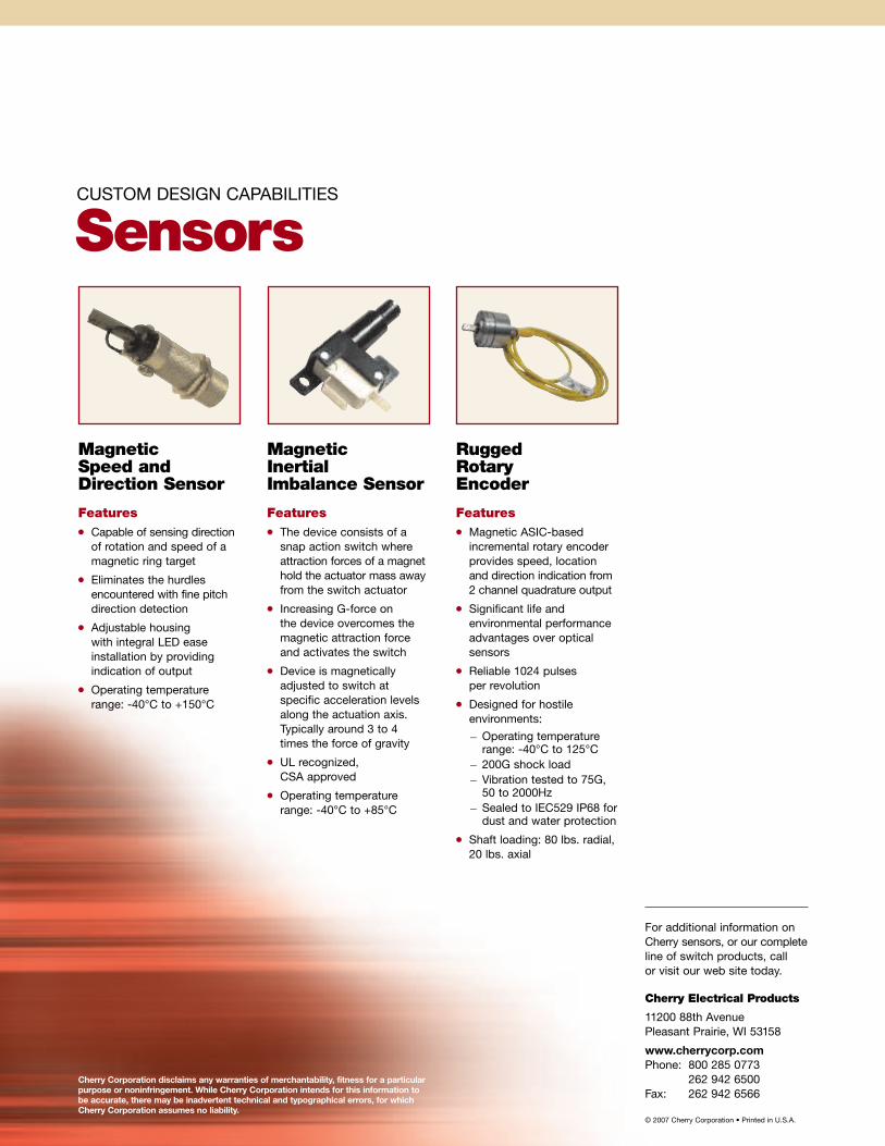
CUSTOM DESIGN CAPABILITIES
Sensors
MagneticInertialImbalance Sensor
Features� The device consists of asnap action switch whereattraction forces of a magnethold the actuator mass awayfrom the switch actuator
� Increasing G-force onthe device overcomes themagnetic attraction forceand activates the switch
� Device is magneticallyadjusted to switch atspecific acceleration levelsalong the actuation axis.Typically around 3 to 4times the force of gravity
� UL recognized,CSA approved
� Operating temperaturerange: -40°C to +85°C
MagneticSpeed andDirection Sensor
Features� Capable of sensing directionof rotation and speed of amagnetic ring target
� Eliminates the hurdlesencountered with fine pitchdirection detection
� Adjustable housingwith integral LED easeinstallation by providingindication of output
� Operating temperaturerange: -40°C to +150°C
RuggedRotaryEncoder
Features� Magnetic ASIC-basedincremental rotary encoderprovides speed, locationand direction indication from2 channel quadrature output
� Significant life andenvironmental performanceadvantages over opticalsensors
� Reliable 1024 pulsesper revolution
� Designed for hostileenvironments:
— Operating temperaturerange: -40°C to 125°C
— 200G shock load— Vibration tested to 75G,50 to 2000Hz
— Sealed to IEC529 IP68 fordust and water protection
� Shaft loading: 80 lbs. radial,20 lbs. axial
For additional information onCherry sensors, or our completeline of switch products, callor visit our web site today.
Cherry Electrical Products
11200 88th AvenuePleasant Prairie, WI 53158
www.cherrycorp.comPhone: 800 285 0773
262 942 6500Fax: 262 942 6566
Cherry Corporation disclaims any warranties of merchantability, fitness for a particularpurpose or noninfringement. While Cherry Corporation intends for this information tobe accurate, there may be inadvertent technical and typographical errors, for whichCherry Corporation assumes no liability.